JP6917066B2 - A rope for suspending a net or a sheet, and a method for connecting the rope for suspending the net or a sheet. - Google Patents
A rope for suspending a net or a sheet, and a method for connecting the rope for suspending the net or a sheet. Download PDFInfo
- Publication number
- JP6917066B2 JP6917066B2 JP2018232017A JP2018232017A JP6917066B2 JP 6917066 B2 JP6917066 B2 JP 6917066B2 JP 2018232017 A JP2018232017 A JP 2018232017A JP 2018232017 A JP2018232017 A JP 2018232017A JP 6917066 B2 JP6917066 B2 JP 6917066B2
- Authority
- JP
- Japan
- Prior art keywords
- rope
- net
- sheet
- suspending
- hanging
- Prior art date
- Legal status (The legal status is an assumption and is not a legal conclusion. Google has not performed a legal analysis and makes no representation as to the accuracy of the status listed.)
- Active
Links
Images


Landscapes
- Emergency Lowering Means (AREA)
Description
本願発明は、各種スポーツの練習用、又は試合用として使用する屋内の練習場、又は災害避難所として使用する屋内空間部において、防球用(間仕切り用)、又は防護用としてその空間部の側面に沿って、又は/及び天井面に沿って吊り張りするネット、又は避難用として屋内空間部を複数に区画するシートを、移動自在に又は固定状態で取り付けるネット又はシートの吊り張り用ロープ、及び該ネット又はシートの吊り張り用のロープの架け渡し方法に関する。According to the present invention, in an indoor practice field used for practicing various sports or for a game, or an indoor space used as a disaster shelter, the side surface of the space is used for ball-proofing (partitioning) or protection. A net or sheet suspension rope for attaching a net that suspends along and / and along the ceiling surface, or a sheet that divides the indoor space into multiple parts for evacuation in a movable or fixed state, and The present invention relates to a method of connecting a rope for suspending the net or a sheet.
従来、屋内空間部において使用する防球・防護用の各種のネットは、複数本の吊り張り用ロープを並行して架け渡し、又は複数本の吊り張り用ロープを交差して架け渡した後、前記吊り張り用ロープにネット体を移動自在に又は固定状態で取り付けることで、各種のネットを吊り張りする。Conventionally, various ball-proof / protective nets used in indoor spaces have a plurality of hanging ropes laid in parallel, or a plurality of hanging ropes crossed and laid. Various nets are suspended by attaching the net body to the suspension rope in a movable or fixed state.
防球・防護用としての天井用ネットを吊り張りする場合は、天井面の下方の側面に沿って枠体を取り付け、該枠体、又は天井の梁を利用して複数本の吊り張り用ロープをそれぞれ取り付けることで、交差する方向に沿って吊り張り用ロープを架け渡した後、前記吊り張り用ロープを利用して前記天井面の形状に応じて形成されたネットを取り付けることで、天井面に沿って天井用ネットを吊り張りする。When suspending a ceiling net for ball protection and protection, attach a frame along the lower side surface of the ceiling surface, and use the frame or ceiling beams to multiple suspension ropes. By attaching each of the above, after the suspension ropes are hung along the intersecting directions, the ceiling surface is attached by attaching the net formed according to the shape of the ceiling surface using the suspension rope. Suspend the ceiling net along.
また間仕切り用ネットを吊り張りする場合は、間仕切り面の上端側に沿って1本又は2本の吊り張り用ロープを架け渡した後、前記吊り張り用ロープに間仕切り面の形状に応じて形成されたネットの上端側を取り付けることで、間仕切り用のネットを吊り張りする。When suspending the partition net, one or two suspending ropes are hung along the upper end side of the partition surface, and then the suspending rope is formed according to the shape of the partition surface. By attaching the upper end side of the rope, the net for partitioning is suspended.
また、避難用として屋内空間部を複数に区画する場合は、対向する側面間に沿って複数本の吊り張り用ロープを所望の間隔を有して架け渡した後、前記吊り張り用ロープの所望の範囲にシートを取り付け、さらに隣合う吊り張り用ロープ間に交差状の別体のシートを取り付けることで、空間部を複数に区画する。Further, when the indoor space portion is divided into a plurality of parts for evacuation, a plurality of suspension ropes are laid along the opposite side surfaces at a desired interval, and then the desired suspension rope is desired. By attaching a sheet in the range of, and then attaching a separate cross-shaped sheet between the adjacent hanging ropes, the space is divided into multiple parts.
上記ネット又はシートを取り付ける吊り張り用ロープは、一般に架け渡す長さに形成されたロープ本体と、該ロープ本体の両端側に取り付けられた連結具とから構成されている。The hanging rope to which the net or the seat is attached is generally composed of a rope main body formed to a length to be bridged and connecting tools attached to both ends of the rope main body.
しかしながら、上記従来の吊り張り用ロープは、枠体、梁、又は支柱部分を利用して取り付けるために、前記枠の形成、支柱への穿孔等の直接的な作業を必要とし、その作業が煩雑であるという欠点があった。However, in order to attach the conventional suspension rope by using the frame body, the beam, or the support column portion, direct work such as forming the frame and drilling the support column is required, and the work is complicated. There was a drawback that it was.
また、前記吊り張り用ロープは、屋内空間部を形成する複数本の支柱部分又は天井の梁等を利用して取り付けるために、前記吊り張り用ロープの取り付け位置が支柱部分又は梁部分に限定され、必ずしも適切な取り付けができないという欠点があった。Further, since the suspension rope is attached by using a plurality of support columns or ceiling beams that form an indoor space, the attachment position of the suspension rope is limited to the support columns or beams. However, there was a drawback that it could not always be installed properly.
また、吊り張り用ロープは予め工場で形成されているために、前記吊り張り用ロープを架け渡した後に、弛み等が発生するために現場での再度の長さ調整が必要であった。Further, since the hanging rope is formed in advance at the factory, it is necessary to adjust the length again at the site because slackening or the like occurs after the hanging rope is hung.
さらに、従来の吊り張り用ロープは、枠体等に強固に連結して固定するために、摩耗等によるメンテナンス時の取り換え作業が煩雑になるという欠点があった。Further, since the conventional hanging rope is firmly connected and fixed to the frame or the like, there is a drawback that the replacement work at the time of maintenance due to wear or the like becomes complicated.
そこで、本発明は屋内空間部の側面に沿って、又は天井面に沿って防球・防護用のネット、又は避難用のシートの取り付けの作業が容易であり、空間部の形状、及び屋内空間部の各面積に応じて自在に防球用等のネット又はシートを吊り張りでき、且つネット又はシートの取り付け作業、及びメンテナンス作業が安全に且つ容易に行うことができるネット又はシートの吊り張り用ロープ、及び該ネット又はシートの吊り張り用ロープの架け渡し方法を提供することを課題とする。Therefore, in the present invention, it is easy to attach a ball-proof / protective net or an evacuation sheet along the side surface or the ceiling surface of the indoor space, and the shape of the space and the indoor space. For suspending nets or sheets, which can freely suspend nets or sheets for ball-proofing, etc. according to each area of the part, and can safely and easily perform net or sheet attachment work and maintenance work. An object of the present invention is to provide a method for connecting a rope and a rope for suspending the net or a sheet.
本願発明の上記課題を解決する手段としてのネット又はシートの吊り張り用ロープは、請求項1に記載のように、屋内空間部の側面、天井面に沿って吊り張りされる防球・防護を目的とするネット、又は屋内空間部を避難用として複数に区画する区画用のシートを、移動自在に又は固定状態で吊り張りするネット又はシートの吊り張り用ロープにおいて、前記吊り張り用ロープがネット又はシートを吊り張りする側面間、天井面の距離に応じ架け渡すことのできる長さに形成されたロープ本体と、該ロープ本体の少なくとも一端側に取り付けられた連結具とから構成され、且つ前記連結具が、側面側、支柱、又は梁部分に予め固定する固定部と該固定部への固定連結部とから構成されていることを特徴とする。As described in
また、本願発明の上記課題を解決する手段としてのネット又はシートの吊り張り用ロープの架け渡し方法は、請求項2に記載のように、屋内空間部の所望の側面間、又は天井面の下方側に沿って複数本の吊り張り用ロープを架け渡した後、該吊り張り用ロープにネットを取り付けることで側面間、又は天井面に沿って防球・防護用としてのネットを吊り張り、又は屋内空間部の対向する側面間に沿って複数本の吊り張り用ロープを架け渡した後、該吊り張り用ロープにシートを取り付けることで屋内空間部を避難用として複数に区画するネット又はシートの吊り張り用ロープの架け渡し方法において、前記吊り張り用ロープを架け渡す際、前記吊り張り用ロープを形成するロープ本体の少なくとも一端側に取り付けられた連結具を側面側、支柱、又は梁部分に直接又は間接的に固定した後、前記ロープ本体の他端側をネット又はシートを吊り張りする距離に応じて緊張状態で連結具を介して対向する側面側、支柱、又は梁部分に固定する、又はロープ本体の他端側をウインチ等を用いて緊張しながら対向する側面側、支柱、又は梁部分に固定することで、吊り張り用ロープを屋内空間部に架け渡すことを特徴とする。Further, as described in
次に、本願発明の請求項1乃至至請求項2に記載のネット又はシートの吊り張り用ロープ、及びネット又はシートの吊り張り用ロープの吊り張り方法の作用効果を説明する。Next, the operation and effect of the net or sheet suspension rope according to
先ず、請求項1に記載のネット又はシートの吊り張り用ロープは、屋内空間部の側面、天井面に沿って吊り張りする防球・防護を目的とするネット、又は屋内空間部を複数に区画する区画用のシートを移動自在に又は固定状態で取り付けるのに使用する吊り張り用ロープ(本願発明において、ロープとはワイヤーロープ、樹脂製ロープ等長尺紐状の総称として使用)である。First, the rope for suspending the net or sheet according to
そのため前記吊り張り用ロープは、屋内空間部の対向する側面間、対向する梁間に対応する長さで緊張状態を維持できるように形成されたロープ本体と、該ロープ本体の少なくとも一端側に取り付けられ側面等に固定するための連結具とから構成されている。Therefore, the suspension rope is attached to a rope body formed so as to maintain a tense state with a length corresponding to the distance between the facing side surfaces and the facing beams of the indoor space portion, and at least one end side of the rope body. It is composed of a connecting tool for fixing to the side surface or the like.
このため、ロープ本体は側面間、対向する梁間等の形状、構造に応じて、ロープ本体を直線状又は水平状態から床面側への略L字状の架け渡し等、常に緊張状態維を持する状態で架け渡すことができる。Therefore, depending on the shape and structure of the rope body between the side surfaces and the opposing beams, the rope body is always in a tense state, such as by bridging the rope body from a linear or horizontal state to the floor side in a substantially L shape. It can be bridged in the state of being.
また前記連結具が、側面、支柱部分、又は梁部分に予め固定する固定部と、該固定部に連結する固定連結部とから構成されているために、少なくともロープ本体の一端側を確実に固定部に取り付けでき、スムーズな吊り張り用ロープの架け渡しを行うことができる。Further, since the connecting tool is composed of a fixing portion that is previously fixed to the side surface, the support column portion, or the beam portion and a fixed connecting portion that is connected to the fixing portion, at least one end side of the rope body is securely fixed. It can be attached to the part, and the rope for hanging can be smoothly hung.
前記連結具がロープ本体の両端側に取り付けられている場合は、予め固定部を側面等に固定した後、固定連結部をそれぞれ連結することで容易に吊り張り用ロープを架け渡すことができる。When the connecting tool is attached to both ends of the rope body, the hanging rope can be easily hung by fixing the fixing portion to the side surface or the like in advance and then connecting the fixed connecting portions respectively.
また、ロープ本体の一端側のみに連結具が設けられている場合は、一端側のみ固定部を予め固定した後、前記固定部に固定連結部を連結することで、一端側を連結し、その後、ロープ本体の他端側を側面又は床面側に固定された滑車、ウインチ等を用いて緊張状態を維持しながら調整することで、吊り張り用ロープを適切に架け渡す。Further, when the connecting tool is provided only on one end side of the rope body, the fixing portion is fixed in advance only on one end side, and then the fixed connecting portion is connected to the fixing portion to connect the one end side and then. By adjusting the other end side of the rope body while maintaining a tense state using a pulley, winch, etc. fixed to the side surface or floor surface side, the rope for suspension is appropriately hung.
このように、請求項1に記載のネット又はシートの吊り張り用ロープは、屋内空間部の側面、天井面等に沿って自在に架け渡すことができる利点がある。As described above, the rope for suspending the net or the sheet according to
また、前記吊り張り用ロープは、常に緊張状態で架け渡すこたができ、防球・防護用、又は避難用として適切に架け渡すことができる利点がある。Further, the hanging rope has an advantage that it can be hung in a tense state at all times, and can be appropriately hung for ball-proof / protective or evacuation.
しかも、その構成が簡易であり、コストの面でも安価に形成することが可能となった。Moreover, its configuration is simple, and it has become possible to form it at low cost in terms of cost.
次に、請求項2に記載のネット又はシートの吊り張り用ロープの架け渡し方法は、屋内空間部の側面、又は天井面の下方側に沿って防球・防護を目的とするネットを吊り張り、又は屋内空間部を複数に区画する区画用のシートを吊り張りするために、側面間の上端側、天井の梁部分、又は所望の高さを有して対向する側面間に吊り張り用ロープを架け渡す。Next, in the method of hanging the net or the rope for suspending the sheet according to
前記吊り張り用ロープを架け渡す際は、先ず前記吊り張り用ロープを形成するロープ本体の少なくとも一端側に取り付けられた連結具を直接側面等に固定、又は連結具を間接的(側面等に設けられた固定部と該固定部に連結する固定連結部とによる)に固定する。When the hanging rope is hung, first, the connecting tool attached to at least one end side of the rope body forming the hanging rope is directly fixed to the side surface or the like, or the connecting tool is indirectly (provided to the side surface or the like). It is fixed to the fixed portion and the fixed connecting portion connected to the fixed portion).
その後、前記ロープ本体の他端側を架け渡す距離に応じて緊張状態で連結具を介して連結して側面等に固定する。After that, the other end side of the rope main body is connected via a connecting tool in a tense state according to the distance over the rope body and fixed to the side surface or the like.
または、前記ロープ本体の他端側をウインチ等を用いて緊張しながら側面等に固定する。Alternatively, the other end side of the rope body is fixed to the side surface or the like while being tense using a winch or the like.
これにより、前記吊り張り用ロープを屋内空間部の所望の位置に複数本架け渡すことができる。As a result, a plurality of the hanging ropes can be hung at a desired position in the indoor space.
このように、請求項2に記載のネット又はシートの吊り張り用ロープの架け渡し方法は、あらゆる側面間、天井面に沿って自在に取り付けできる利点がある。As described above, the method of connecting the net or the rope for suspending the sheet according to
また、その作業効率が良くスムーズな架け渡し作業を行うことができる。In addition, the work efficiency is good and smooth bridging work can be performed.
本願発明のネット又はシートの吊り張り用ロープ、及びネット又はシートの吊り張り用ロープの架け渡し方法について図面を用いて説明する。The net or sheet suspension rope of the present invention and the method of connecting the net or sheet suspension rope will be described with reference to the drawings.
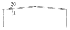
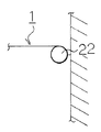
図1は本願発明のネット又はシート吊り張り用ロープの一実施例を示す概略説明側面図であり、図2は複数本のネット又はシートの吊り張り用ロープを格子状に架け渡した状態を示す概略説明平面図であり、図3は天井面に沿って架け渡したネット又はシートの吊り張り用ロープを示す概略説明側面図であり、図4はロープ本体の他端側に滑車を用いた場合を示す概略説明側面図であり、図5はロープ本体の他端側にウインチを用いた場合を示す概略説明側面図であり、図6及び図7は吊り張り用ロープを間接的に連結する場合を示す概略説明平面図であり、図8は支柱(H鋼)に連結具を連結する場合を示す概略説明平面図であり、図9は屋内空間部の天井面に沿って、側面間にネット又はシートの吊り張り用ロープを架け渡す場合を示す概略説明側面図である。FIG. 1 is a schematic explanatory side view showing an embodiment of a net or sheet suspension rope of the present invention, and FIG. 2 shows a state in which a plurality of net or sheet suspension ropes are laid in a grid pattern. Schematic explanatory plan view, FIG. 3 is a schematic explanatory side view showing a rope for suspending a net or a seat spanned along a ceiling surface, and FIG. 4 is a case where a pulley is used on the other end side of the rope body. 5 is a schematic explanatory side view showing a case where a winch is used on the other end side of the rope body, and FIGS. 6 and 7 are cases where the suspension rope is indirectly connected. FIG. 8 is a schematic explanatory plan view showing a case where a connecting tool is connected to a support (H steel), and FIG. 9 is a schematic explanatory plan view showing a case where a connecting tool is connected to a support (H steel), and FIG. 9 is a net between the side surfaces along the ceiling surface of the indoor space portion. Alternatively, it is a schematic explanatory side view showing a case where a rope for suspending a sheet is hung.
図10、図11及び図12はネット又はシートの吊り張り用ロープの架け渡し方法を示すフローチャートである。FIGS. 10, 11 and 12 are flowcharts showing a method of connecting a rope for suspending a net or a sheet.
本願発明のネット又はシートの吊り張り用ロープ1は、屋内空間部の側面間、又は天井面の長さに応じて緊張状態で架け渡すことのできる長さに形成されたロープ本体2と、前記ロープ本体2の少なくとも一端側に取り付けられた連結具3とから構成されている。The
前記連結具3の取り付けは、前記ロープ本体2の両端側に取り付けることで両端側をそれぞれ側面等に連結して固定し、前記吊り張り用ロープ1を側面間等に架け渡す取り付け方法と、さらに次のように方法とがある。The connecting
即ち、前記連結具3を前記ロープ本体2の一端側のみに取り付けることで、連結具3の取り付けられたロープ本体2の一端側のみ側面等に連結して固定し、前記ロープ本体2の他端側は側面等に固定したエンドレス方式のウインチ22、又は逆回転防止付き滑車23を介して緊張状態で取り付ける方法がある。That is, by attaching the connecting
このため、前記ロープ本体2の他端側は前記エンドレス方式のウインチ22に連結、又は逆回転防止付き滑車23を介して床面側に連結することで、常にロープ本体2を緊張状態とすべく調整することができ、吊り張り用ロープ1の適切な架け渡しを可能とする。尚、前記他端側はエンドレス方式のウインチ22に限定されるものでなく、巻き取り方式のウインチ(図示せず)を用いてロープ本体2を巻き取り緊張状態とすることも可能である。Therefore, the other end side of the
前記連結具3は、屋内空間部を形成する支柱(H鋼を含む各種の支持部材)10部分、又は側面等に固定する固定部4と、前記ロープ本体2の端部に固定し、前記固定部4に連結する固定連結部5とから構成されている。The
前記固定部4は、側面、支柱10、又は天井の梁部分にボルト等で取り付けて固定する固定板4Aと、前記固定板4Aに取り付ける略U字状の留め具4Bとから構成されている。The fixing portion 4 is composed of a fixing
前記固定連結部5は、前記留め具4Bに連結するためのリング環5Aで形成されている。The fixed connecting portion 5 is formed of a ring ring 5A for connecting to the
前記吊り張り用ロープ1の架け渡しにおいて、その隣合う吊り張り用ロープ1の間を調整する場合は、前記各固定部4の留め具4Bに棒状体36又は連結ロープ体37を挿通することで、側面に沿って前記棒状体36又は連結ロープ体37を取り付け、前記棒状体36又は連結ロープ体37に前記リング環5Aを連結することで、スライド自在に吊り張り用ロープ1を架け渡すことも可能である。When adjusting between the
特に支柱10部分、又は側面の強度のある部分と架け渡す位置が相違する場合は、前記棒状体36又は連結ロープ体37を使用することが適切である。In particular, when the position of the support is different from that of the
前記リング環5Aは前記棒状体36又は連結ロープ体37に直接挿通され、螺子等で固定するストッパー体(図示せず)、又は前記棒状体36又は連結ロープ体37に取り付けることで固定するストッパー体(図示せず)を用いてその移動を阻止することができる。The ring ring 5A is directly inserted into the rod-shaped
尚、前記連結具4は上記構成に限定されるものでなく、固定板4Aと固定連結部4Bとが一体的に構成することも可能である。The connecting tool 4 is not limited to the above configuration, and the fixing
前記ロープ本体2には、ネット又はシートを取り付ける取付具(図示せず)が移動自在に又は固定状態で取り付けられている。これにより、ネット又はシートを容易にロープ本体2に取り付けできる。A fitting (not shown) for attaching a net or a seat is attached to the
本願発明のネット又はシートの吊り張り用ロープ1は上記のように構成され、次に、該吊り張り用ロープ1を屋内空間部の天井面に沿って架け渡し、天井用ネットを吊り張りする場合について説明する。The net or
先ず、屋内空間部の天井面の下方側の側面及び天井面の梁部分を利用して連結具3を形成する固定部4の固定板4Aを側面及び梁に所望の幅を有して取り付けて固定し、該固定板4Aに留め具4Bをそれぞれ取り付ける。First, the fixing
次に、前記留め具4Bに天井面の面積に応じて形成された複数本のロープ本体2の両端側に取り付けられた固定連結部5のリング環5Aを連結することで、吊り張り用ロープ1をそれぞれ天井面に沿って架け渡す。Next, the hanging
前記吊り張り用ロープ1の架け渡しは、天井面の大きさに応じて、一方向に沿って複数本の吊り張り用ロープ1を並行して架け渡す場合と、大きな空間部を有する天井面又は円弧状のドーム形の天井面の場合は、複数本の吊り張り用ロープ1を格子状に架け渡すことで、落下防止の効果の向上を目的とする。Depending on the size of the ceiling surface, the
これにより、前記複数本の吊り張り用ロープ1に天井面の形状に応じて形成されたネット(図示せず)を直接又は取付具を介して間接的取り付けることで、天井用ネットを天井面に沿って吊り張りする。As a result, the ceiling net can be attached to the ceiling surface by directly or indirectly attaching a net (not shown) formed according to the shape of the ceiling surface to the plurality of
この際、支柱(H鋼)10部分に固定板4Aを取り付ける際は、H鋼部分に孔を穿孔することなく、2枚の固定板4AでH鋼部分を挟持した状態とし、前記各固定板4Aと押さえ板4Eとをボルト4Cで連結することで、H鋼に強固に固定することができる。At this time, when the fixing
これにより、天井面の構造上の強度に影響を与えることなく適切に天井用ネットを吊り張りできる。As a result, the ceiling net can be appropriately suspended without affecting the structural strength of the ceiling surface.
このように、天井面に沿って容易に、且つ適切に吊り張り用ロープ1を架け渡すことができる。In this way, the hanging
次に、避難用として屋内空間部を複数に区画する場合について説明する。Next, a case where the indoor space is divided into a plurality of parts for evacuation will be described.
先ず、対向するそれぞれの側面の補強部分に前記固定板4Aを取り付けるとともに、固定板4Aに留め具4Bを取り付ける。尚、固定板4Aと留め具4Bとが一体的に形成されている場合は、固定板4Aのみを取り付ける。First, the fixing
次に、前記留め具4Bに沿って棒状体36又は連結ロープ体37を挿通することで、側面用の固定部4を取り付ける。Next, the fixing portion 4 for the side surface is attached by inserting the rod-shaped
そして、前記棒状体36又は連結ロープ体37に側面間に応じて形成されたロープ本体2の両端側に取り付けられた固定連結部5のリング環5Aを取り付けることで、複数本の吊り張り用ロープ1を架け渡す。Then, by attaching the ring rings 5A of the fixed connecting portions 5 attached to both ends of the rope
この際、各吊り張り用ロープ1を棒状体36又は連結ロープ体37に沿って移動しストッパーで固定することで、隣合う吊り張り用ロープ1間の距離を調整する。At this time, the distance between the
また、吊り張り用ロープ1の一端側のみに固定連結部5が設けられている場合は、一端側のみ前記棒状体36又は連結ロープ体37に連結した後、他端側は側面に固定された逆回転防止付き滑車23を介して床面側に取り付けられた固定板4Aの留め具4Bに連結して固定することで、吊り張り用ロープ1を常に緊張状態で架け渡すことができる。When the fixed connecting portion 5 is provided only on one end side of the hanging
また、他端側を側面に固定されたエンドレス方式のウインチ22を用いて緊張状態で引っ張ることで、適切に緊張状態で吊り張り用ロープ1を架け渡すことができる。Further, by pulling the other end side in a tense state using an
その後、前記吊り張り用ロープ1に区画用のシート(図示せず)を取り付け、さらに隣合う吊り張り用ロープ1間に別体のシート(図示せず)を取り付けることで、屋内空間部を複数に区画することができる。After that, a partition sheet (not shown) is attached to the hanging
このように、容易に吊り張り用ロープ1を架け渡すことができ、しかも、その間隔を自在に調整することができる。In this way, the hanging
1−吊り張り用ロープ、2−ロープ本体、3−連結具、4−固定部、5−固定連結部1-Rope for suspension, 2-Rope body, 3-Connector, 4-Fixed part, 5-Fixed connecting part
Claims (2)
前記吊り張り用ロープが前記ネット又はシートを吊り張りする側面間、天井面の距離に応じて緊張状態で架け渡すことのできる長さに形成されたロープ本体と、該ロープ本体の一端部のみに取り付けられた連結具とから構成され、
且つ前記連結具が、前記ネット又はシートを吊り張りする一方側の側面側、支柱、又は梁部分に予め固定する固定部と該固定部への固定連結部とから構成され、
前記固定部は、前記ネット又はシートを吊り張りする一方側の側面側、支柱、又は梁部分にボルトで取り付けて固定する固定板と、前記固定板に取り付ける略U字状の留め具とから構成され、
前記固定連結部は、前記留め具に連結するためのリング環で形成され、
前記固定部の留め具に棒状体又は連結ロープ体を挿通することで前記棒状体又は連結ロープ体を取り付け、且つ前記棒状体又は連結ロープ体に前記リング環を連結することで、スライド自在に吊り張り用ロープを架け渡し、
前記ロープ本体の他端側は、前記ネット又はシートを吊り張りする他方側に固定されたウインチ又は逆回転付き滑車を介して、前記ネット又はシートを吊り張りする他方側に緊張状態で固定せしめられることを特徴とするネット又はシートの吊り張り用ロープ。 A net for the purpose of ball-proofing / protection suspended along the side surface of the indoor space, the ceiling surface, or a sheet for partitioning the indoor space into multiple sections for evacuation, in a movable or fixed state. In the hanging net or the hanging rope of the seat
Only on the rope body formed so that the hanging rope can be bridged between the side surfaces for suspending the net or the sheet and in a tension state according to the distance between the ceiling surfaces, and one end of the rope body. Consists of attached fittings,
Further, the connecting tool is composed of a fixing portion that is previously fixed to the side surface side, the support column, or the beam portion on one side that suspends the net or the sheet, and a fixing connecting portion to the fixing portion.
The fixing portion is composed of a fixing plate that is bolted and fixed to a side surface side, a support, or a beam portion on one side that suspends the net or a sheet, and a substantially U-shaped fastener that is attached to the fixing plate. Being done
The fixed connecting portion is formed of a ring ring for connecting to the fastener.
The rod-shaped body or the connecting rope body is attached by inserting the rod-shaped body or the connecting rope body into the fastener of the fixing portion, and the ring ring is connected to the rod-shaped body or the connecting rope body so as to be slidably suspended. Overhang the tension rope,
The other end of the rope body is tensioned to the other side of the net or seat via a winch or pulley with reverse rotation fixed to the other side of the net or seat. A rope for suspending a net or a sheet, which is characterized by the fact that the rope is used.
屋内空間部の所望の側面間、又は天井面の下方側に沿って複数本の吊り張り用ロープを架け渡した後、該吊り張り用ロープにネットを取り付けることで側面間、又は天井面に沿って防球・防護を目的としてネットを吊り張り、又は屋内空間部の対向する側面間に沿って複数本の吊り張り用ロープを架け渡した後、該吊り張り用ロープにシートを取り付けることで、屋内空間部を避難用として複数に区画するネット又はシートの吊り張り用ロープの架け渡し方法において、
前記吊り張り用ロープを架け渡す際、前記吊り張り用ロープを形成するロープ本体の少なくとも一端側に取り付けられた連結具を前記側面側、支柱、又は梁部分に直接又は間接的に固定した後、
前記ロープ本体の他端側をウインチ等を用いて緊張しながら対向する側面側、支柱、又は梁部分に固定することで吊り張り用ロープを屋内空間部に架け渡すことを特徴とするネット又はシートの吊り張り用ロープの架け渡し方法。 A method of connecting a net or sheet suspension rope using the net or sheet suspension rope according to claim 1.
After a plurality of hanging ropes are laid between desired sides of the indoor space or along the lower side of the ceiling surface, a net is attached to the hanging ropes between the sides or along the ceiling surface. By suspending the net for the purpose of ball-proofing and protection, or by suspending a plurality of suspension ropes along the opposing side surfaces of the indoor space, and then attaching a sheet to the suspension rope, the sheet is attached. In the method of bridging the rope for suspending the net or sheet that divides the indoor space into multiple parts for evacuation.
When the suspension rope is hung, after the connecting tool attached to at least one end side of the rope body forming the suspension rope is directly or indirectly fixed to the side surface side, the support column, or the beam portion.
A net or sheet characterized in that the hanging rope is bridged over the indoor space by fixing the other end side of the rope body to the opposite side surface side, the support column, or the beam portion while being tense with a winch or the like. How to hang a rope for hanging.
Priority Applications (1)
| Application Number | Priority Date | Filing Date | Title |
|---|---|---|---|
| JP2018232017A JP6917066B2 (en) | 2018-11-22 | 2018-11-22 | A rope for suspending a net or a sheet, and a method for connecting the rope for suspending the net or a sheet. |
Applications Claiming Priority (1)
| Application Number | Priority Date | Filing Date | Title |
|---|---|---|---|
| JP2018232017A JP6917066B2 (en) | 2018-11-22 | 2018-11-22 | A rope for suspending a net or a sheet, and a method for connecting the rope for suspending the net or a sheet. |
Publications (3)
| Publication Number | Publication Date |
|---|---|
| JP2020081814A JP2020081814A (en) | 2020-06-04 |
| JP2020081814A5 JP2020081814A5 (en) | 2021-03-11 |
| JP6917066B2 true JP6917066B2 (en) | 2021-08-11 |
Family
ID=70905269
Family Applications (1)
| Application Number | Title | Priority Date | Filing Date |
|---|---|---|---|
| JP2018232017A Active JP6917066B2 (en) | 2018-11-22 | 2018-11-22 | A rope for suspending a net or a sheet, and a method for connecting the rope for suspending the net or a sheet. |
Country Status (1)
| Country | Link |
|---|---|
| JP (1) | JP6917066B2 (en) |
-
2018
- 2018-11-22 JP JP2018232017A patent/JP6917066B2/en active Active
Also Published As
| Publication number | Publication date |
|---|---|
| JP2020081814A (en) | 2020-06-04 |
Similar Documents
| Publication | Publication Date | Title |
|---|---|---|
| US20070039276A1 (en) | Concrete reinforcer and method | |
| JP7006958B2 (en) | Protective net upholstery structure | |
| JP2008255735A (en) | Ceiling fall prevention structure and method of preventing ceiling from falling | |
| JP6917066B2 (en) | A rope for suspending a net or a sheet, and a method for connecting the rope for suspending the net or a sheet. | |
| JP6561391B2 (en) | Fail-safe ceiling structure | |
| JP2019078162A5 (en) | ||
| JP6089328B1 (en) | Net body or sheet body and method for suspending the net body or sheet body | |
| JP6548131B2 (en) | Net for indoor space, and method of hanging the net for indoor space | |
| JP6380879B1 (en) | Net for ceiling in indoor space and method for suspending net for ceiling in indoor space | |
| JP5769094B2 (en) | NET REINFORCING ROPE AND NET SUSTAINING METHOD USING THE REINFORCING ROPE | |
| JP6733098B1 (en) | Ceiling net or sheet for indoor space and method for suspending ceiling net or sheet for indoor space | |
| JP2016079767A (en) | Suspended ceiling structure | |
| JP6304523B2 (en) | Suspended ceiling structure | |
| KR101965111B1 (en) | Safety ties for double bottom structures | |
| JP6152980B2 (en) | Suspended ceiling structure | |
| JP6319676B1 (en) | Net for indoor space portion and method for suspending net for indoor space portion | |
| JP6264599B2 (en) | Suspended ceiling structure | |
| JP6501440B1 (en) | Mounting method of fall prevention net structure, fall prevention net structure, and fixing bracket provided for fall prevention net structure | |
| JP6454948B2 (en) | NET INSTALLATION LOCKING TOOL, NET FOR BALL-PROOFING WITH NET INSTALLATION LOCKING TOOL, AND METHOD OF INSTALLING THE NETWORK INSTALLATION LOCKING TOOL ON GLASS-PROOFING NET | |
| JP6120115B1 (en) | Net body for indoor or outdoor space, and method for suspending net body for indoor or outdoor space | |
| JP6142460B2 (en) | Net body or sheet body and method for suspending net body or sheet body | |
| JP6724277B2 (en) | Ceiling sheet for indoor space and method for suspending ceiling sheet for indoor space | |
| JP3805861B2 (en) | Pulley fixing bracket for building a steel pile under the road | |
| JP2018178708A (en) | Suspended ceiling structure | |
| JP6842026B2 (en) | Suspension body of indoor space and suspension method of suspension body of indoor space |
Legal Events
| Date | Code | Title | Description |
|---|---|---|---|
| A871 | Explanation of circumstances concerning accelerated examination |
Free format text: JAPANESE INTERMEDIATE CODE: A871 Effective date: 20201218 |
|
| A521 | Written amendment |
Free format text: JAPANESE INTERMEDIATE CODE: A523 Effective date: 20201218 |
|
| A621 | Written request for application examination |
Free format text: JAPANESE INTERMEDIATE CODE: A621 Effective date: 20201218 |
|
| A975 | Report on accelerated examination |
Free format text: JAPANESE INTERMEDIATE CODE: A971005 Effective date: 20210303 |
|
| RD02 | Notification of acceptance of power of attorney |
Free format text: JAPANESE INTERMEDIATE CODE: A7422 Effective date: 20210310 |
|
| A131 | Notification of reasons for refusal |
Free format text: JAPANESE INTERMEDIATE CODE: A131 Effective date: 20210330 |
|
| A521 | Written amendment |
Free format text: JAPANESE INTERMEDIATE CODE: A523 Effective date: 20210526 |
|
| TRDD | Decision of grant or rejection written | ||
| A01 | Written decision to grant a patent or to grant a registration (utility model) |
Free format text: JAPANESE INTERMEDIATE CODE: A01 Effective date: 20210706 |
|
| A61 | First payment of annual fees (during grant procedure) |
Free format text: JAPANESE INTERMEDIATE CODE: A61 Effective date: 20210712 |
|
| R150 | Certificate of patent or registration of utility model |
Ref document number: 6917066 Country of ref document: JP Free format text: JAPANESE INTERMEDIATE CODE: R150 |