JP6916632B2 - Anomaly detection method for railway vehicle compressors - Google Patents
Anomaly detection method for railway vehicle compressors Download PDFInfo
- Publication number
- JP6916632B2 JP6916632B2 JP2017032786A JP2017032786A JP6916632B2 JP 6916632 B2 JP6916632 B2 JP 6916632B2 JP 2017032786 A JP2017032786 A JP 2017032786A JP 2017032786 A JP2017032786 A JP 2017032786A JP 6916632 B2 JP6916632 B2 JP 6916632B2
- Authority
- JP
- Japan
- Prior art keywords
- compressor
- pressure
- information
- vehicle
- abnormality
- Prior art date
- Legal status (The legal status is an assumption and is not a legal conclusion. Google has not performed a legal analysis and makes no representation as to the accuracy of the status listed.)
- Active
Links
Images

Landscapes
- Electric Propulsion And Braking For Vehicles (AREA)
Description
本発明は、鉄道車両においてエアブレーキや空気バネに使用する圧縮空気を発生するコンプレッサもしくは蓄圧系の故障発生を事前に予測するためにコンプレッサの状態を監視し異常を検知する方法に関するものである。 The present invention relates to a method of monitoring the state of a compressor and detecting an abnormality in order to predict in advance the occurrence of a failure of a compressor or a pressure accumulator system that generates compressed air used for an air brake or an air spring in a railroad vehicle.
鉄道車両には、エアブレーキや空気バネに使用する圧縮空気を発生するコンプレッサが搭載されている。このコンプレッサが長期間の運用によって部品が劣化もしくは故障し、それにより圧縮能力が低下した場合、1回当たりの稼働時間が長くなりトータルの消費電力が増加するおそれがある。また、コンプレッサが故障してから修理するのでは、維持コストが高くなってしまう。
従来、コンプレッサの制御技術として、例えばコンプレッサの異常検出回数を計数するカウンタを備え、カウンタの計数値が所定の回数に達した場合には、コンプレッサのモータを停止して、再起動を禁止する技術がある(特許文献1)。
Railroad vehicles are equipped with compressors that generate compressed air used for air brakes and air springs. If the compressor deteriorates or breaks down due to long-term operation and the compression capacity decreases as a result, the operating time per operation may increase and the total power consumption may increase. In addition, if the compressor is repaired after it breaks down, the maintenance cost will be high.
Conventionally, as a compressor control technology, for example, a technology that includes a counter that counts the number of times an abnormality is detected in the compressor, and when the count value of the counter reaches a predetermined number of times, stops the compressor motor and prohibits restarting. (Patent Document 1).
また、測定したデータを分析して装置の状態を判定する技術として、実車データを蓄積するためのデータ蓄積部と、シミュレーションデータを特異値分解して第1の特徴量を求めるとともに実車データを特異値分解して第2の特徴量を求めるSVD処理部とを設け、第1の特徴量を第1のマハラノビス距離に変換して第1のマハラノビス距離に基づいて電車制御装置の状態を判定するための異常判定しきい値を設定し、第2の特徴量を第2のマハラノビス距離に変換し、第2のマハラノビス距離と異常判定しきい値とを比較した結果に基づいて電車制御装置の状態を判定するようにした発明がある(特許文献2)。 In addition, as a technique for analyzing the measured data to determine the state of the device, a data storage unit for accumulating actual vehicle data and a singular value decomposition of simulation data to obtain the first feature amount and singularizing the actual vehicle data. In order to provide an SVD processing unit that obtains a second feature amount by value decomposition, convert the first feature amount into a first Mahalanobis distance, and determine the state of the train control device based on the first Mahalanobis distance. The abnormality judgment threshold value is set, the second feature amount is converted to the second Mahalanobis distance, and the state of the train control device is determined based on the result of comparing the second Mahalanobis distance and the abnormality judgment threshold value. There is an invention for determining (Patent Document 2).
上記特許文献1に開示されているコンプレッサの制御技術は、電気自動車の空気調和装置に用いられるコンプレッサに関するものであり、負荷の大きさや消費電力、冷媒温度等を監視して、これらの値が所定の範囲から外れた場合には、コンプレッサに異常が生じたと判断してコンプレッサのモータを停止して、再起動を禁止するというものである。しかし、電気自動車の空気調和装置であれば、コンプレッサを停止してもそれほど問題はないが、鉄道車両においては、圧縮空気をエアブレーキに使用しており圧縮空気がないと車両の走行に支障を来たすため、コンプレッサを停止させることはできないという課題がある。
The compressor control technology disclosed in
また、鉄道車両用のコンプレッサは、蓄圧管の圧力が所定値以下に下がると稼働させ、蓄圧管の圧力が所定値以上に上がると稼働を停止するという制御を行なっており、走行中における稼働タイミングがばらばらである。つまり、車両の走行停止中にコンプレッサが稼働することもあれば、走行中にコンプレッサが稼働することもある。また、コンプレッサは外気温度の影響も受ける。そのため、単純にコンプレッサのモータの温度を監視するだけでは異常の発生を早期に検知することができないという課題がある。
本発明は、上記課題を解決するためになされたもので、鉄道車両の機器モニタリングデータを利用して、外気温度や乗車率、車両の走行速度等の条件の差異に影響されずに、コンプレッサ(蓄圧系を含む)の異常の発生を高い精度で検知することができる鉄道車両用コンプレッサの異常検知方法を提供することを目的とする。
In addition, the compressor for railway vehicles is controlled so that it operates when the pressure of the accumulator pipe drops below a predetermined value and stops when the pressure of the accumulator pipe rises above a predetermined value. Are disjointed. That is, the compressor may be operated while the vehicle is stopped, or the compressor may be operated while the vehicle is running. The compressor is also affected by the outside air temperature. Therefore, there is a problem that the occurrence of an abnormality cannot be detected at an early stage by simply monitoring the temperature of the compressor motor.
The present invention has been made to solve the above problems, and uses the equipment monitoring data of a railroad vehicle to make a compressor (a compressor) without being affected by differences in conditions such as outside air temperature, occupancy rate, and running speed of the vehicle. It is an object of the present invention to provide a method for detecting an abnormality in a compressor for a railway vehicle, which can detect the occurrence of an abnormality (including a pressure accumulator system) with high accuracy.
なお、上記特許文献2に開示されている発明は、実車データを取得し蓄積する点、取得したデータを統計的に分析する点で本発明と類似するものの、コンプレッサではなく電車制御装置の異常を検知するものであるとともに、シミュレーションデータを使用するため事前にシミュレーションを行う必要がある点や、分析の際にマハラノビス距離を用いて判定している点で、本発明とは異なる。
The invention disclosed in
上記課題を解決するために、本発明に係る鉄道車両用コンプレッサの異常検知方法は、
鉄道車両に搭載されたデータ収集システムによって収集されたコンプレッサの稼働情報、ブレーキ装置の稼働情報、蓄圧系の圧力情報、空気バネの圧力情報、車両重量に関する情報、車両の走行速度情報および外気温度情報を受信し記憶する第1ステップと、
記憶された情報の中から、ブレーキ装置の操作のない時間における蓄圧系の圧力情報を、コンプレッサごとに抽出する第2ステップと、
抽出された蓄圧系の圧力情報に基づいて、所定時間内における蓄圧系の圧力上昇量を、コンプレッサごとに算出する第3ステップと、
算出された圧力上昇量のうち所定期間の中でコンプレッサ動作1回当たり最大のものを選択する第4ステップと、
前記所定時間内における空気バネの圧力変位を算出する第5ステップと、
前記車両重量に関する情報に基づいて前記所定時間中における乗車率を算出する第6ステップと、
少なくとも前記空気バネの圧力変位と、乗車率と、外気温度と、車両速度とを説明変数とし、かつ蓄圧系の圧力上昇量を従属変数として重回帰分析により回帰モデル式を立て、当該回帰モデル式と前記第1ステップで収集した蓄圧系の圧力情報、前記第5ステップで算出した空気バネの圧力変位、車両重量に関する情報および車両の走行速度情報とを用いてコンプレッサの状態を判断する処理を行う第7ステップと、
を含むようにしたものである。
In order to solve the above problems, the method for detecting an abnormality in a compressor for a railway vehicle according to the present invention is
Compressor operation information, brake device operation information, pressure accumulator pressure information, air spring pressure information, vehicle weight information, vehicle running speed information and outside air temperature information collected by a data collection system mounted on a railroad vehicle. The first step of receiving and storing
From the stored information, the second step of extracting the pressure information of the accumulator system during the time when the brake device is not operated for each compressor, and
Based on the extracted pressure information of the accumulator system, the third step of calculating the pressure increase amount of the accumulator system within a predetermined time for each compressor, and
The fourth step of selecting the maximum amount of pressure rise calculated per compressor operation within a predetermined period, and
The fifth step of calculating the pressure displacement of the air spring within the predetermined time, and
The sixth step of calculating the occupancy rate during the predetermined time based on the information on the vehicle weight, and
At least the pressure displacement of the air spring, the occupancy rate, the outside air temperature, and the vehicle speed are used as explanatory variables, and the pressure rise amount of the accumulator system is used as the dependent variable to formulate a regression model formula by multiple regression analysis. The process of determining the state of the compressor is performed using the pressure information of the accumulator system collected in the first step, the pressure displacement of the air spring calculated in the fifth step, the information on the vehicle weight, and the traveling speed information of the vehicle. 7th step and
Is included.
上記方法によれば、蓄圧系(空気タンク)の圧力、空気バネの圧力、車両重量、車両速度、外気温度等の情報を収集して、乗車率および空気バネの圧力変位量を算出し、外気温度、乗車率および車両速度と空気バネの圧力変位量を説明変数として重回帰分析の手法によって回帰モデル式を立て、該回帰モデル式と収集した外気温度、乗車率および車両速度の各情報と空気バネの圧力変位量とを用いて蓄圧系の圧力上昇量を推定し、コンプレッサもしくはコンプレッサに接続された蓄圧系の状態を判断するため、乗車率や車両の走行速度等の条件の差異に影響されずにコンプレッサ(蓄圧系を含む)の異常の発生を高い精度で検知することができる。 According to the above method, information such as the pressure of the accumulator system (air tank), the pressure of the air spring, the vehicle weight, the vehicle speed, and the outside air temperature is collected, the occupancy rate and the pressure displacement amount of the air spring are calculated, and the outside air is calculated. A regression model formula was established by the method of multiple regression analysis using the temperature, occupancy rate, vehicle speed, and pressure displacement of the air spring as explanatory variables, and the return model formula, collected information on the outside air temperature, occupancy rate, and vehicle speed, and air. Since the pressure rise of the accumulator system is estimated using the pressure displacement amount of the spring and the state of the compressor or the accumulator system connected to the compressor is judged, it is affected by the difference in conditions such as the occupancy rate and the running speed of the vehicle. It is possible to detect the occurrence of an abnormality in the compressor (including the accumulator system) with high accuracy without using it.
ここで、望ましくは、前記第7ステップにおいては、前記回帰モデル式を用いて算出した蓄圧系の圧力上昇量の予測値と、前記第3ステップで算出された圧力上昇量の実績値との差分を求め、該差分をプロットしたグラフにおける集団を内包する位置に境界線を設定して、コンプレッサの状態を判断するようにする。
上記のように、算出した蓄圧系の圧力上昇量の予測値と圧力上昇量の実績値との差分を求め、差分をプロットしたグラフにおける集団を内包する位置に境界線を設定し、設定された境界線を用いてコンプレッサ(蓄圧系を含む)の状態を判断するため、コンプレッサ(蓄圧系を含む)の異常の発生を高い精度でかつ比較的簡単な演算処理によって検知することができる。
Here, preferably, in the seventh step, the difference between the predicted value of the pressure increase amount of the accumulator system calculated by using the regression model formula and the actual value of the pressure increase amount calculated in the third step. Is obtained, and a boundary line is set at a position including the group in the graph in which the difference is plotted so that the state of the compressor can be judged.
As described above, the difference between the calculated predicted value of the pressure rise in the accumulator system and the actual value of the pressure rise was obtained, and the boundary line was set at the position including the group in the graph plotting the difference. Since the state of the compressor (including the accumulator system) is determined using the boundary line, the occurrence of an abnormality in the compressor (including the accumulator system) can be detected with high accuracy and relatively simple arithmetic processing.
また、望ましくは、前記第7ステップにおいては、前記回帰モデル式を用いて算出した圧力上昇量の予測値と実績値との差分が前記境界線を越えた回数を計数し、その計数値が予め設定した所定回数よりも大きいか否か判定し、計数値が予め設定した所定回数よりも大きい場合に異常を知らせる情報を出力するようにする。
このように、蓄圧系の圧力上昇量の予測値と実績値との差分が境界線を越えた回数を計数し、当該計数値が予め設定した前記所定回数よりも大きいか否か判定して異常を知らせる情報を出力することにより、比較的簡単な処理により異常の発生の有無の判定を行うことができるとともに、判定結果および異常報知の信頼性を高めることができる。
Further, preferably, in the seventh step, the number of times the difference between the predicted value and the actual value of the pressure increase calculated by using the regression model formula crosses the boundary line is counted, and the counted value is calculated in advance. It is determined whether or not it is larger than the set predetermined number of times, and when the count value is larger than the preset predetermined number of times, the information notifying the abnormality is output.
In this way, the number of times the difference between the predicted value and the actual value of the pressure rise amount of the accumulator system crosses the boundary line is counted, and it is determined whether or not the counted value is larger than the predetermined number of times, which is abnormal. By outputting the information informing the above, it is possible to determine the presence or absence of an abnormality by a relatively simple process, and it is possible to improve the reliability of the determination result and the abnormality notification.
さらに、望ましくは、前記第7ステップの前記コンプレッサの状態を判断する処理においては、前記境界線を越えた回数の変化率を算出し、当該変化率が予め設定した所定値よりも大きいか否か判定し、変化率が予め設定した所定値よりも大きい場合に異常を知らせる情報を出力するようにする。
このように、蓄圧系の圧力上昇量の予測値と実績値との差分が境界線を越えた回数の変化率を算出し、変化率が予め設定した所定値よりも大きいか否か判定して異常を知らせる情報を出力することにより、回数のみに基づいて判定する場合に比べていち早く異常の発生を検知して報知することができる。
Further, preferably, in the process of determining the state of the compressor in the seventh step, the rate of change of the number of times the boundary line is crossed is calculated, and whether or not the rate of change is larger than a predetermined value set in advance. Judgment is made, and when the rate of change is larger than a predetermined value set in advance, information for notifying an abnormality is output.
In this way, the rate of change of the number of times the difference between the predicted value and the actual value of the pressure rise of the accumulator system crosses the boundary line is calculated, and it is determined whether or not the rate of change is larger than the preset predetermined value. By outputting the information notifying the abnormality, it is possible to detect and notify the occurrence of the abnormality earlier than in the case of determining based only on the number of times.
また、望ましくは、前記第7ステップにおいて設定する前記回帰モデル式の説明変数には前記空気バネの圧力変位として、1車両につき左右の複数の前記空気バネのうち左右一つずつの変位を用いるようにする。
1車両につき左右それぞれ複数の前記空気バネが設けられている場合に、回帰モデル式の説明変数の空気バネの圧力変位として、すべての空気バネの圧力変位を用いても良いが、上記のように、1車両につき左右複数の前記空気バネのうち左右一つずつの圧力変位を用いることによって、少ない計算量で比較的精度の高い異常検知を行うことができる。
Further, preferably, as the explanatory variable of the regression model equation set in the seventh step, the displacement of one of the left and right of the plurality of left and right air springs per vehicle is used as the pressure displacement of the air spring. To.
When a plurality of the air springs are provided on the left and right sides of one vehicle, the pressure displacements of all the air springs may be used as the pressure displacements of the air springs, which are the explanatory variables of the regression model equation, as described above. By using the pressure displacement of one of the left and right air springs for each vehicle, it is possible to detect anomalies with relatively high accuracy with a small amount of calculation.
本発明によれば、鉄道車両の機器モニタリングデータを利用して、外気温度や乗車率、車両の走行速度等の条件の差異に影響されずに、コンプレッサ(蓄圧系を含む)の異常の発生を高い精度で検知することができるという効果がある。 According to the present invention, the occurrence of an abnormality in the compressor (including the accumulator system) is caused by using the equipment monitoring data of the railway vehicle without being affected by the difference in conditions such as the outside air temperature, the occupancy rate, and the traveling speed of the vehicle. It has the effect of being able to detect with high accuracy.
以下、本発明に係るコンプレッサの異常検知方法の実施形態について、図面を参照しながら説明する。
本発明に係るコンプレッサの異常検知方法は、走行中の列車において取集した蓄圧系(空気タンク)の圧力、空気バネの圧力、車両重量、車両速度等のデータに基づいて、各コンプレッサの状態を把握し、コンプレッサが異常を起こす早い段階で異常の発生を検知するものである。そこで、異常検知に必要なデータの収集システムおよび該システムにより収集されたデータに基づいてコンプレッサの状態を判定し報知するコンプレッサの異常検知システムの構成について、図1を用いて先ず説明する。
Hereinafter, embodiments of the compressor abnormality detection method according to the present invention will be described with reference to the drawings.
The method for detecting an abnormality of a compressor according to the present invention determines the state of each compressor based on data such as pressure of an accumulator system (air tank), pressure of an air spring, vehicle weight, and vehicle speed collected in a running train. It is intended to grasp and detect the occurrence of an abnormality at an early stage when the compressor causes an abnormality. Therefore, the configuration of the data collection system required for abnormality detection and the compressor abnormality detection system that determines and notifies the state of the compressor based on the data collected by the system will be described first with reference to FIG.
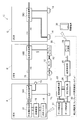
図1には、走行中の列車からデータを収集するシステム10および収集されたデータに基づいてコンプレッサの異常を検知する異常検知システム20の概要が示されている。
図1に示されているように、1編成の列車の各車両A,B,C……には、数両に1台の割合でコンプレッサ11および空気タンク12とブレーキコントローラ13が搭載された車両(図では車両B)が連結されているとともに、各車両には前後左右計4か所に空気バネ14が設けられている。なお、図1においては、図示の都合で、車両Cの空気バネ14のみを示している。
FIG. 1 shows an outline of a
As shown in FIG. 1, each vehicle A, B, C ... of one train is equipped with a
そして、上記空気タンク12には圧力センサが、または空気バネ14には圧力センサおよび車両の重量(上下変位量)を検出する重量計(変位計)が設けられているとともに、いずれかの車両(例えば先頭車両)の車軸端には速度発電機のような速度計TGおよび外気温度を検出する温度センサTSが設けられている。また、複数の車両に設けられている空気タンク12同士は図示しないパイプで接続されており、該パイプに各車両の空気バネ14が接続されている。ブレーキコントローラ13は、空気タンク12の圧力が所定値以下に下がるとコンプレッサの稼働を開始させ、空気タンクの圧力が上がって所定値に達するとコンプレッサの稼働を停止させる制御を実行するように構成されている。
The
本実施形態におけるデータ収集システム10は、列車に設けられているデータ伝送路15を利用して、速度計TGと温度センサTSと各車両の空気バネ14の圧力センサおよび変位計からデータを収集可能に構成されている。この場合、データのサンプリング周期としては、例えば0.2秒とすることが考えられる。
中央端末装置17は、データ伝送路15を介して収集したデータを、電動車識別情報(号車情報)と共に例えばハードディスクや半導体メモリのような記憶装置を備えた記録装置18に格納し、無線通信機能を有する送信ユニット19が地上側装置(20)へ収集データを定期的に送信するように構成されている。
The
The
また、中央端末装置17は、速度計TGにより検出された情報(車軸の回転速度)に基づいて車両の走行速度および走行距離データを算出し、記録装置18に格納する。
記録装置18には、当該列車の識別情報(編成番号)および始発駅情報が格納されており、中央端末装置17が収集データを送信する際には、収集した温度データ、空気圧データ、車両走行速度データおよび走行距離データと共に列車の識別情報および始発駅情報を送信する。なお、記録装置18は、サーバーであっても良い。
Further, the
The
コンプレッサの異常検知システム20は、車上側のデータ収集システム10の送信ユニット19から送信された収集データ等を受信するデータ受信部21と、受信したデータを記憶するハードディスクや半導体メモリのようなデータ格納部22を備える。また、コンプレッサの異常検知システム20は、受信したデータを列車識別情報および電動車識別情報ごとに分析して異常検知の判断の目安となる境界線を算出する境界線算出部23と、算出された境界線と収集されたデータとを比較してコンプレッサの異常状態を判定する判定処理部24と、判定結果を記憶する結果格納部25と、アラート(警報)情報を外部の携帯情報端末30等へ送信するアラート発信部26を備える。
The compressor
なお、上記境界線算出部23および判定処理部24の機能は、CPU(マイクロプロセッサ)のような演算装置、ROMやRAMなどの記憶装置、キーボードのような入力装置および表示装置のような出力装置を備えたパーソナルコンピュータと、その記憶装置に記憶されるプログラムとによって実現することができる。かかるパーソナルコンピュータのハードウェア構成自体は自明であるのでその図示は省略する。
次に、コンプレッサの異常検知システム20における境界線算出処理とモータ異常検知判定処理の詳細を、本発明を開発するに至った経緯とともに説明する。
The functions of the boundary
Next, the details of the boundary line calculation process and the motor abnormality detection determination process in the compressor
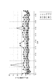
先ず、本発明者らは、コンプレッサや蓄圧系の部品が劣化すると、コンプレッサが空気タンク内の空気を所定の圧力まで上昇させるのに要する時間(以下、蓄圧時間と称する)すなわち1回当たりのコンプレッサ稼働時間が長くなるだろうと予測して、約半年にわたって営業運転中の車両においてコンプレッサの駆動開始時刻と停止時刻を記録し、記録した時刻データから1回当たりのコンプレッサ稼働時間(蓄圧時間)を計算によって求めた。その結果を図2に示す。図2は、縦軸にコンプレッサの稼働時間(蓄圧時間)、横軸に日付をとって約半年間の値をプロットしたものである。 First, the present inventors, when the compressor and the components of the accumulator system deteriorate, the time required for the compressor to raise the air in the air tank to a predetermined pressure (hereinafter referred to as the accumulator time), that is, the compressor per time. Predicting that the operating time will be long, record the drive start time and stop time of the compressor in a vehicle that has been in commercial operation for about half a year, and calculate the compressor operating time (accumulation time) per time from the recorded time data. Asked by. The result is shown in FIG. In FIG. 2, the vertical axis is the operating time (accumulation time) of the compressor, and the horizontal axis is the date, and the values for about half a year are plotted.
図2より、コンプレッサの稼働時間(蓄圧時間)は大きくばらついていることが分かる。そのため、稼働時間(蓄圧時間)に関してしきい値を設け、稼働時間(蓄圧時間)がこのしきい値を超えたらコンプレッサが異常と判定するのは難しいと予想された。そこで、次に、稼働時間(蓄圧時間)が大きくばらつく原因について考察した。 From FIG. 2, it can be seen that the operating time (accumulation time) of the compressor varies greatly. Therefore, it is expected that it will be difficult to set a threshold value for the operating time (accumulation time) and determine that the compressor is abnormal if the operating time (accumulation time) exceeds this threshold value. Therefore, next, we considered the cause of the large variation in operating time (accumulation time).
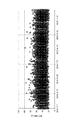
ばらつき原因を知るため、先ず、空気タンクに圧力計を取り付けて圧力の変化を測定し、稼働時間(蓄圧時間)の比較的長いケースと短いケースについて、空気タンクの圧力の変化の仕方を調べた。また、空気タンク内の圧力は、圧縮空気の消費と関連すると考え、エアブレーキのノッチの状態も取得した。
図3は、縦軸に空気タンク内の圧力とブレーキノッチ位置、横軸に時間をとってコンプレッサの動作1回当たりにおける圧力の変化を示したもので、(A)は稼働時間(蓄圧時間)が比較的長い場合のもの、(B)は稼働時間(蓄圧時間)が比較的短い場合のものである。
In order to know the cause of the variation, first, a pressure gauge was attached to the air tank to measure the change in pressure, and the way the pressure in the air tank changed was investigated for cases with relatively long operating time (accumulation time) and cases with short operating time (accumulation time). .. In addition, the pressure in the air tank was considered to be related to the consumption of compressed air, and the state of the notch of the air brake was also acquired.
In FIG. 3, the vertical axis shows the pressure in the air tank and the brake notch position, and the horizontal axis shows the change in pressure per operation of the compressor. (A) shows the operating time (accumulation time). Is a case where is relatively long, and (B) is a case where the operating time (accumulation time) is relatively short.
図3(A),(B)において、緩やかに右上がりしている線は空気タンク内の圧力の変化を示す。図3(A)において、上下に大きく振れているのはブレーキノッチの位置変化を示す。図3(B)においては、ブレーキノッチの位置は変化していない。
また、左側の縦軸におけるP1は空気タンク内の圧力が下がってコンプレッサの稼働を開始する時の圧力、P2は空気タンク内の圧力が上がってコンプレッサの稼働を停止する時の圧力である。このような制御が、ブレーキコントローラ13によって実施されている。図3(A),(B)において、Ta,Tbはそれぞれコンプレッサの稼働時間を表わしている。
In FIGS. 3A and 3B, the line gradually rising to the right indicates the change in pressure in the air tank. In FIG. 3A, a large swing up and down indicates a change in the position of the brake notch. In FIG. 3B, the position of the brake notch has not changed.
Further, P1 on the left vertical axis is the pressure when the pressure in the air tank decreases to start the operation of the compressor, and P2 is the pressure when the pressure in the air tank increases and the operation of the compressor is stopped. Such control is performed by the
なお、図3の(A)と(B)とでは、横軸のスケールが異なっており、(A)の場合の稼働時間(蓄圧時間)Taは約80秒、(B)の場合の稼働時間(蓄圧時間)Tbは約18秒であった。また、ブレーキノッチ位置に関しては、ノッチの値が大きいほど強い制動を掛けていることを意味している。図3(A)の場合、ブレーキノッチ位置が頻繁に変化しているので、ブレーキ操作がされていたことが分かる。一方、図3(B)の場合、ブレーキノッチ位置は、連続して「0」であるので、ブレーキ操作がされていなかったことが分かる。
図3より、走行中にブレーキ操作をしている時にコンプレッサが稼働すると、所定の圧力に達するまでの時間が長くなり、ブレーキ操作をしていない時にコンプレッサが稼働すると、所定の圧力に達するまでの時間が短くなることが確認された。
The scales on the horizontal axis are different between (A) and (B) in FIG. 3, and the operating time (accumulation time) Ta in the case of (A) is about 80 seconds, and the operating time in the case of (B). (Accumulation time) Tb was about 18 seconds. As for the brake notch position, the larger the notch value, the stronger the braking. In the case of FIG. 3A, since the brake notch position changes frequently, it can be seen that the brake operation has been performed. On the other hand, in the case of FIG. 3B, since the brake notch position is continuously "0", it can be seen that the brake operation has not been performed.
From FIG. 3, when the compressor is operated while the brake is being operated during driving, it takes a long time to reach the predetermined pressure, and when the compressor is operated when the brake is not being operated, it is until the predetermined pressure is reached. It was confirmed that the time was shortened.
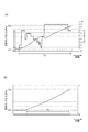
次に、本発明者らは、ブレーキ操作をしていない状態でコンプレッサが稼働している時のデータを抽出してコンプレッサの稼働時間の大小を調べた。すると、まだコンプレッサの稼働時間にかなりのばらつきがあった。そこで、エアブレーキ以外に圧縮エアを消費している装置としての空気バネが関係しているのではないかと考え、ブレーキ操作をしていない状態でコンプレッサが稼働している時のデータの中から、比較的コンプレッサの稼働時間が長いものと短いものとを抽出した。図4に、その結果を示す。
図4は、縦軸に空気タンクの圧力、横軸に時間をとってコンプレッサの動作1回当たりにおける圧力の変化を示したもので、◆印は稼働時間(蓄圧時間)の比較的短かった際の圧力測定値をプロットしたもの、□印は稼働時間(蓄圧時間)の比較的長かった際の圧力測定値をプロットしたものである。
Next, the present inventors extracted data when the compressor was operating in a state where the brake was not operated, and investigated the magnitude of the operating time of the compressor. Then, there was still considerable variation in the operating time of the compressor. Therefore, I thought that the air spring as a device that consumes compressed air other than the air brake might be related, and from the data when the compressor is operating without braking, We extracted the ones with relatively long operating time and the ones with relatively short operating time. The result is shown in FIG.
In Fig. 4, the vertical axis shows the pressure of the air tank and the horizontal axis shows the change in pressure per operation of the compressor, and the ◆ mark indicates when the operating time (accumulation time) is relatively short. The pressure measurement value of is plotted, and the □ mark is the pressure measurement value when the operating time (accumulation time) is relatively long.
次に、図4の圧力変化のうちコンプレッサの稼働時間(蓄圧時間)の比較的短かった場合と稼働時間(蓄圧時間)の比較的長かった場合のそれぞれにおける列車の走行区間を調べてみた。すると、稼働時間が短いのは駅出発直後に直線が長く続いている区間で、稼働時間が長いのは駅出発直後にカーブが存在する区間であることが分かった。これは、車両がカーブを走行する際には、車体がローリングし易く、空気バネが車体のローリングを抑制すべく動作することが多いので、空気バネの動作/非動作がコンプレッサの稼働時間のばらつきに影響しているためであると考えた。 Next, among the pressure changes in FIG. 4, the traveling sections of the train were examined when the operating time (accumulation time) of the compressor was relatively short and when the operating time (accumulation time) was relatively long. Then, it was found that the short operating time is the section where the straight line continues for a long time immediately after the departure from the station, and the long operating time is the section where the curve exists immediately after the departure from the station. This is because when the vehicle travels on a curve, the vehicle body is easy to roll, and the air spring often operates to suppress the rolling of the vehicle body. Therefore, the operation / non-operation of the air spring varies in the operating time of the compressor. I thought it was because it affected.
上記の知見から、コンプレッサの稼働時間の差異の影響を受けずにコンプレッサおよび蓄圧系の劣化状態を、データ分析で検出するには、ブレーキ操作の有無や車体のローリングの有無(空気バネの動作)を考慮するのが望ましいとの結論に達した。また、コンプレッサの稼働中に圧縮空気の消費量が少ないほど稼働中の圧力上昇が大きく、コンプレッサの本来の蓄圧能力を見極めるのに有効であるとの結論に達した。
そこで、収集した測定データの中から、走行中にブレーキ操作がなかったときの測定データ(空気タンクの圧力)を抽出して、分析を行うこととした。
From the above findings, in order to detect the deterioration state of the compressor and accumulator system by data analysis without being affected by the difference in the operating time of the compressor, the presence or absence of braking operation and the presence or absence of rolling of the vehicle body (air spring operation) We have come to the conclusion that it is desirable to consider. It was also concluded that the smaller the amount of compressed air consumed during the operation of the compressor, the greater the increase in pressure during operation, which is effective in determining the original pressure accumulation capacity of the compressor.
Therefore, it was decided to extract the measurement data (pressure of the air tank) when there was no braking operation during running from the collected measurement data and analyze it.
ところで、コンプレッサの蓄圧能力は、空気タンク内の圧力MRをP1からP2まで高めるのに要した時間幅Tの大小、あるいは所定の時間内に上昇した空気タンク内の圧力△MRから判断することができる。つまり、コンプレッサの動作開始後のある時点t1の空気タンク内の圧力をMR1、t1からT時間後の時点t2での空気タンク内の圧力をMR2とおくと、(MR2−MR1)/Tを指標としてコンプレッサの蓄圧能力を判断することができる。なお、時間幅Tを長くすればするほどその間にエアブレーキや空気バネが動作する可能性が高くなるので、あまり長い時間幅を設定するのは望ましくない。 By the way, the accumulator capacity of the compressor can be judged from the magnitude of the time width T required to increase the pressure MR in the air tank from P1 to P2, or the pressure ΔMR in the air tank that has risen within a predetermined time. can. That is, if the pressure in the air tank at a certain time point t1 after the start of operation of the compressor is MR1 and the pressure in the air tank at a time point t2 T hours after t1 is MR2, (MR2-MR1) / T is used as an index. It is possible to judge the accumulator capacity of the compressor. The longer the time width T, the higher the possibility that the air brake and the air spring will operate during that time, so it is not desirable to set a too long time width.
そこで、本発明者らは、t1をコンプレッサの動作開始時点に設定したときの最適な時間幅Tについて検討した。
具体的には、同一区間(直線区間)の走行中に取得した空気タンク内の圧力データを用いて、時間幅Tをそれぞれ1秒、3秒、5秒、10秒、13秒、15秒に変えて、空気タンク内の圧力MRの上昇量を計算した。その結果を図5に示す。図5より、5秒以下ではときどき平均から外れた値が見られるが、10秒以上になるとほぼ安定した値が得られることが分かった。そこで、コンプレッサの蓄圧能力を判断する指標として、次のモデル式
a=(MR2−MR1)/T
を用い、評価することとした。そして、適切な時間幅Tとして10秒を選択することとした。なお、この10秒は、適用する列車の車種に応じて変わることもある。
Therefore, the present inventors have studied the optimum time width T when t1 is set at the operation start time of the compressor.
Specifically, using the pressure data in the air tank acquired while traveling in the same section (straight section), the time width T is set to 1 second, 3 seconds, 5 seconds, 10 seconds, 13 seconds, and 15 seconds, respectively. Then, the amount of increase in the pressure MR in the air tank was calculated. The result is shown in FIG. From FIG. 5, it was found that a value deviating from the average was sometimes seen at 5 seconds or less, but a substantially stable value was obtained at 10 seconds or more. Therefore, as an index for determining the accumulator capacity of the compressor, the following model formula a = (MR2-MR1) / T
Was used for evaluation. Then, it was decided to select 10 seconds as an appropriate time width T. Note that this 10 seconds may change depending on the type of train to which the train is applied.
次に、本発明者らは、上記評価方法を検証するため、定置状態(速度0km/h)でコンプレッサを稼働させて空気タンク内の圧力MRを測定し、動作開始後10秒間における空気タンク内の圧力MRの上昇量を算出してみた。その結果、定置状態でのMR上昇量は、走行中のものと大きく異なることが明らかとなった。
このことから、MR上昇量は車両速度等も関係していると予想されるので、MR上昇量と車両速度との関係について調べた。その結果を図6に示す。図6より、MR上昇量と車両速度との間に相関(右肩上がりの傾向)がみられるものの、同一の車両速度でもMR上昇量に大きなバラツキがみられることから、車両速度以外の要因もあるとの結論に達した。
Next, in order to verify the above evaluation method, the present inventors measured the pressure MR in the air tank by operating the compressor in a stationary state (
From this, it is expected that the amount of MR increase is also related to the vehicle speed, etc., so the relationship between the amount of MR increase and the vehicle speed was investigated. The result is shown in FIG. From FIG. 6, although there is a correlation between the amount of MR increase and the vehicle speed (the tendency to increase to the right), there is a large variation in the amount of MR increase even at the same vehicle speed, so factors other than vehicle speed are also present. I came to the conclusion that there is.
そこで、次に、走行中は車両がローリングを起こし、該ローリングを抑えるため空気バネが作動するので、空気バネが圧縮空気を消費していることに着目して、車両速度と共に、各車両の前後左右に設けられている空気バネの圧力を走行中の列車から取得することとし、さらに影響因子として考えられる外気温度、乗車率を取得して統計的分析を実施するため、これらの値を測定する試験を行なった。なお、乗車率は、従来から空気バネに設けられている車両重量を測定する重量計の測定値から換算することができるので、それを利用して取得した。 Then, next, the vehicle rolls while traveling, and the air spring operates to suppress the rolling. Therefore, paying attention to the fact that the air spring consumes compressed air, the front and rear of each vehicle are combined with the vehicle speed. The pressures of the air springs provided on the left and right are obtained from the running train, and these values are measured in order to obtain the outside air temperature and occupancy rate, which are considered to be influential factors, and perform statistical analysis. The test was conducted. Since the occupancy rate can be converted from the measured value of the weight scale for measuring the weight of the vehicle, which has been conventionally provided in the air spring, the occupancy rate was obtained by using the measured value.
次に、本発明者らは、前記試験で得られたデータに対して、MR上昇量を従属変数(目的変数)とし、空気バネの圧力変位(10秒間における最大値と最小値との差)と、乗車率と、外気温度と、車両速度とを説明変数として、重回帰分析を実施した。なお、空気バネは1車両当たり4個(AS1〜AS4)あるが、左側の2個(AS1とAS3)と右側の2個(AS2とAS4)はそれぞれ似たような挙動を示すと予想されたので、左右から1個ずつ(AS1とAS2)を選択して、それらの変位を説明変数とした。 Next, the present inventors set the amount of MR rise as the dependent variable (objective variable) with respect to the data obtained in the above test, and the pressure displacement of the air spring (difference between the maximum value and the minimum value in 10 seconds). A multiple regression analysis was performed using the occupancy rate, the outside air temperature, and the vehicle speed as explanatory variables. There are four air springs (AS1 to AS4) per vehicle, but the two on the left side (AS1 and AS3) and the two on the right side (AS2 and AS4) are expected to behave similarly. Therefore, one by one (AS1 and AS2) was selected from the left and right, and their displacements were used as explanatory variables.
また、当初、上記5つの説明変数の他に、速度の2乗や他の車両の乗車率等も説明変数として用いた重回帰分析によるスクリーニングを行なった結果、上記5つの説明変数とすれば充分であると判断した。
上記5つの説明変数を用いた重回帰式は、次式
従属変数(MR上昇量)=a+b×(AS1変位)+c×(AS2変位)
+d×(乗車率)+e×(外気温度)+f×(車両速度) ……(1)
で示される。なお、AS1とAS2の代わりに、AS3とAS4の値(変位)を使用するようにしても良い。
In addition to the above five explanatory variables, the above five explanatory variables are sufficient as a result of screening by multiple regression analysis using the square of speed and the occupancy rate of other vehicles as explanatory variables. Judged to be.
The multiple regression equation using the above five explanatory variables is the following equation Dependent variable (MR increase amount) = a + b × (AS1 displacement) + c × (AS2 displacement)
+ D × (ride rate) + e × (outside air temperature) + f × (vehicle speed) …… (1)
Indicated by. The values (displacement) of AS3 and AS4 may be used instead of AS1 and AS2.
次に、前記試験により0.2秒周期で取得した約半年分の実測値の10秒平均を用いて、重回帰分析による統計的処理を実施することによって、上記式(1)における定数aおよび係数b,c,d,e,fを決定した。その結果、次のモデル式
MR上昇量=4.683−0.047×(AS1変位)−0.061×(AS2変位)
+0.18×(乗車率)−0.023×(外気温度)+0.037×(車両速度) ……(2)
が得られた。なお、上記式(1)における定数aおよび係数b,c,d,e,fの値は、重回帰分析機能を有する種々のソフトウェアが市販されているので、それを利用して得ることができる。
Next, by performing statistical processing by multiple regression analysis using the 10-second average of the measured values for about half a year obtained in the 0.2-second cycle in the above test, the constant a in the above equation (1) and The coefficients b, c, d, e and f were determined. As a result, the following model formula MR increase amount = 4.683-0.047 × (AS1 displacement) -0.061 × (AS2 displacement)
+0.18 x (ride rate) -0.023 x (outside air temperature) +0.037 x (vehicle speed) …… (2)
was gotten. The values of the constant a and the coefficients b, c, d, e, and f in the above equation (1) can be obtained by using various software having a multiple regression analysis function on the market. ..
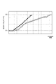
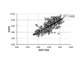
図7は、上記モデル式(2)から予測されたMR上昇量の予測値と実測値との相関を示したもので、相関係数R2は、0.624であった。これより、予測値と実測値との相関は良好であり、上記モデル式(2)の予測精度は充分に満足できるものであることが分かる。 FIG. 7 shows the correlation between the predicted value of the MR increase amount predicted from the model formula (2) and the actually measured value, and the correlation coefficient R 2 was 0.624. From this, it can be seen that the correlation between the predicted value and the measured value is good, and the prediction accuracy of the above model equation (2) is sufficiently satisfactory.
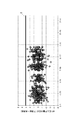
次に、上記モデル式(2)の予測値と実測値との差分をとってその時間的な変化について調べた。図8に、その結果を、横軸に日をとって示す。図8より、日数が経過するほどつまりコンプレッサの劣化が進むほど、予測値と実測値との差分のばらつきが大きくなることを見出した。このことから、予測値と実測値との差分をプロットした図8のグラフにおいて、標本の集団を包含する位置に境界線Eを設け、該境界線を用いて異常検知の判定を行なえば、コンプレッサの異常を検知することができるとの結論に達した。 Next, the difference between the predicted value and the actually measured value of the above model formula (2) was taken and the temporal change was investigated. FIG. 8 shows the results on the horizontal axis with days. From FIG. 8, it was found that the variation in the difference between the predicted value and the measured value increases as the number of days elapses, that is, as the deterioration of the compressor progresses. From this, in the graph of FIG. 8 in which the difference between the predicted value and the measured value is plotted, a boundary line E is provided at a position including a group of samples, and an abnormality detection is determined using the boundary line. We have come to the conclusion that it is possible to detect anomalies in.
そして、本発明者らは、前記分析結果から、以下に説明するようなコンプレッサの異常検知方法を開発した。
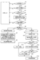
図9は、図1に示すコンプレッサの異常検知システム20の境界線算出部23および判定処理部24によって実行される処理の手順を示すフローチャートである。なお、以下に説明する処理は、検知対象の列車が複数のコンプレッサおよび蓄圧系を備える場合、コンプレッサおよび蓄圧系ごとに実行してもよいし、車種や線区毎にまとめて実施してもよい。
Then, the present inventors have developed a compressor abnormality detection method as described below from the analysis results.
FIG. 9 is a flowchart showing a processing procedure executed by the boundary
図9に示すように、コンプレッサの異常検知システム20は、先ず、監視対象のコンプレッサ(CMP)が稼働中であるか否か判定する(ステップS1)ここで、コンプレッサが稼働中でない(No)と判定すると境界線の算出のための計算をしないで当該処理を終了する。また、コンプレッサが稼働中である(Yes)と判定すると、ステップS2へ移行して、コンプレッサが10秒間稼働中であるか否か判定する。ここで、コンプレッサが10秒間稼働中でない(No)と判定すると境界線の算出のための計算をしないで当該処理を終了する。
As shown in FIG. 9, the compressor
また、ステップS2で、コンプレッサが10秒間稼働中である(Yes)と判定すると、ステップS3へ移行して、ブレーキが10秒間操作されたか否か判定する。そして、ブレーキが10秒間操作された(No)と判定すると境界線の算出のための計算をしないで当該処理を終了する。また、ブレーキが10秒間操作されていない(Yes)と判定すると、ステップS4へ移行して、10秒間の空気タンク内圧力(MR圧)の上昇量およびそのときの当該車両の乗車率を算出する。続いて、ステップS5へ進み、算出されたMR圧の上昇量が1日または1回の稼働中の最大値であるか否か判定する。ここで、最大値でない(No)と判定すると境界線の算出のための計算をしないで当該処理を終了する。一方、ステップS5で、最大値である(Yes)と判定すると、ステップS6へ移行する。 Further, if it is determined in step S2 that the compressor is operating for 10 seconds (Yes), the process proceeds to step S3, and it is determined whether or not the brake has been operated for 10 seconds. Then, when it is determined that the brake has been operated for 10 seconds (No), the process is terminated without performing the calculation for calculating the boundary line. If it is determined that the brake has not been operated for 10 seconds (Yes), the process proceeds to step S4, and the amount of increase in the air tank pressure (MR pressure) for 10 seconds and the occupancy rate of the vehicle at that time are calculated. .. Subsequently, the process proceeds to step S5, and it is determined whether or not the calculated amount of increase in MR pressure is the maximum value during daily or one operation. Here, if it is determined that the value is not the maximum value (No), the process is terminated without performing the calculation for calculating the boundary line. On the other hand, if it is determined in step S5 that the maximum value is (Yes), the process proceeds to step S6.
ステップS6では、評価対象の車両(列車)が営業開始から1年以内のものであるか否か判定する。営業開始から1年以内の判定を行うのは、正常な状態のコンプレッサの稼動による実績データを判断の基礎データとして取得するとともに、通年(全季節)のデータを取得しておくのが望ましいためである。なお、本実施例の異常検知方法は、コンプレッサの劣化による異常の発生を早期に検知するためのものであるので、通年のデータを取得できれば、営業開始から1年以内の車両についてのデータ取得に限定されるものでない。 In step S6, it is determined whether or not the vehicle (train) to be evaluated is within one year from the start of business. Judgment is made within one year from the start of business because it is desirable to acquire the actual data of the operation of the compressor in the normal state as the basic data of the judgment and the data for the whole year (all seasons). be. The abnormality detection method of this embodiment is for detecting the occurrence of an abnormality due to deterioration of the compressor at an early stage. Therefore, if the data for the whole year can be acquired, the data for the vehicle within one year from the start of business can be acquired. Not limited.
上記ステップS6で、営業開始から1年以内のものである(Yes)と判定すると、しきい値となる境界線の算出処理を開始し、ステップS7において、空気バネの圧力変位(AS変位)、乗車率、外気温度、車両速度を用いて重回帰分析の手法により、前述したモデル式を使用して空気タンク内圧力MRの上昇量の予測値を算出し、その予測値と実測値の差分を取り、その差分をプロットした図8に示すグラフにおける標本の集団を内包する境界線Eを決定する。そして、ステップS7で決定した境界線情報を記憶装置に格納して処理を終了する(ステップS8)。 In step S6 above, if it is determined that the product is within one year from the start of business (Yes), the calculation process of the boundary line serving as the threshold value is started, and in step S7, the pressure displacement (AS displacement) of the air spring, Using the multiple regression analysis method using the occupancy rate, outside air temperature, and vehicle speed, the predicted value of the increase in air tank pressure MR is calculated using the model formula described above, and the difference between the predicted value and the measured value is calculated. The boundary line E including the group of samples in the graph shown in FIG. 8 in which the difference is plotted is determined. Then, the boundary line information determined in step S7 is stored in the storage device, and the process ends (step S8).
一方、上記ステップS6で、評価対象車両が営業開始から1年以内でない(No)と判定すると、ステップS9へ進んで、前記回帰モデル式を用いて算出したMR上昇量とステップS9で記憶装置に格納した境界線情報とを比較して、境界線を越えた回数をカウントする(ステップS10)。そして、境界線を越えた回数(カウント値)が所定の回数以上であるか否か判定する(ステップS11)。ここで、境界線を越えた回数(カウント値)が所定の回数以上である(Yes)と判定すると、ステップS12へ移行してアラートを発信(もしくはアラームを発報)してから、ステップS16へ進んで判定結果を記憶装置に格納して当該処理を終了する。 On the other hand, if it is determined in step S6 that the vehicle to be evaluated is not within one year (No) from the start of business, the process proceeds to step S9, and the MR increase amount calculated using the regression model formula and the storage device in step S9. The number of times the boundary line is crossed is counted by comparing with the stored boundary line information (step S10). Then, it is determined whether or not the number of times (count value) crossing the boundary line is equal to or more than a predetermined number of times (step S11). Here, if it is determined that the number of times the boundary line has been crossed (count value) is equal to or greater than a predetermined number of times (Yes), the process proceeds to step S12 to issue an alert (or issue an alarm), and then to step S16. Proceed to store the determination result in the storage device and end the process.
また、ステップS11で、境界線を越えた回数(カウント値)が所定の回数以上でない(No)と判定すると、ステップS13へ進んでカウント値の変化率(前日比)を算出し、算出された変化率が所定値以上であるか否か判定する(ステップS14)。そして、算出された変化率が所定値以上である(Yes)と判定すると、ステップS15へ移行して、アラートを発信してから、ステップS16へ進んで判定結果を記憶装置に格納して当該処理を終了する。変化率が所定値以上であるか否かの判定(ステップS15)を行うことで、境界線を越える回数が少なくても急に回数の変化率が大きくなった場合にはアラートを発信して注意を促すことができる。 Further, in step S11, if it is determined that the number of times the boundary line is crossed (count value) is not more than a predetermined number (No), the process proceeds to step S13 to calculate the rate of change of the count value (compared to the previous day). It is determined whether or not the rate of change is equal to or greater than a predetermined value (step S14). Then, when it is determined that the calculated rate of change is equal to or greater than a predetermined value (Yes), the process proceeds to step S15 to send an alert, and then proceeds to step S16 to store the determination result in the storage device and perform the process. To finish. By determining whether or not the rate of change is equal to or greater than a predetermined value (step S15), even if the number of times the boundary line is crossed is small, if the rate of change suddenly increases, an alert is issued to be careful. Can be encouraged.
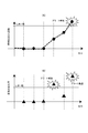
図10(A)にステップS11の判定のイメージを、図10(B)にステップS14の判定のイメージを、横軸に日付をとって示す。
コンプレッサが故障する前であっても、コンプレッサの劣化が進むと稼働開始後所定圧力に達するまでの時間が長くなり、境界線を越える回数が次第に多くなる。また、コンプレッサの劣化が進むと、境界線を越える回数の変化率が次第に高くなると予想される。図9に示すコンプレッサの異常検知処理のフローチャートでは、図10(A)に示すように境界線を越える回数が次第に多くなって所定回数をオーバーするか、図10(B)に示すように回数の変化率が急に高くなって所定値をオーバーすると、アラートを発信するため、コンプレッサの故障の予兆を的確に捉えて異常の発生を報知することができる。
FIG. 10A shows an image of the determination in step S11, FIG. 10B shows an image of the determination in step S14, and the horizontal axis shows the date.
Even before the compressor breaks down, as the deterioration of the compressor progresses, it takes a long time to reach a predetermined pressure after the start of operation, and the number of times the boundary line is crossed gradually increases. Further, as the deterioration of the compressor progresses, it is expected that the rate of change in the number of times the boundary line is crossed will gradually increase. In the flowchart of the abnormality detection process of the compressor shown in FIG. 9, as shown in FIG. 10 (A), the number of times the boundary line is crossed gradually increases and exceeds a predetermined number of times, or as shown in FIG. 10 (B), the number of times is exceeded. When the rate of change suddenly increases and exceeds a predetermined value, an alert is sent, so that it is possible to accurately grasp the sign of compressor failure and notify the occurrence of an abnormality.
以上本発明者によってなされた発明を実施形態に基づき具体的に説明したが、本発明は前記実施形態に限定されるものではない。例えば、図9のフローチャートでは、ステップS11で境界線を越えた回数(カウント値)が所定の回数以上であると判定したとき、またはステップS14で回数の変化率が所定値以上であると判定したときにアラートを発信しているが、ステップS11で境界線を越えた回数が所定の回数以上であると判定しかつステップS14で回数の変化率が所定値以上であると判定したとき(論理積条件成立時)にアラートを発信するようにしてもよい。 Although the invention made by the present inventor has been specifically described above based on the embodiment, the present invention is not limited to the above embodiment. For example, in the flowchart of FIG. 9, when it is determined in step S11 that the number of times the boundary line is crossed (count value) is equal to or greater than a predetermined number of times, or in step S14 it is determined that the rate of change in the number of times is equal to or greater than a predetermined value. Occasionally, an alert is sent, but when it is determined in step S11 that the number of times the boundary line has been crossed is equal to or greater than a predetermined number of times, and in step S14 it is determined that the rate of change in the number of times is equal to or greater than a predetermined value (logical product). An alert may be sent when the condition is satisfied).
また、上記実施例のコンプレッサの異常検知方法では、図9のステップS7で異常判定の目安となる境界線を算出する際に、重回帰分析の手法により作成したモデル式を使用して算出したMR上昇量の予測値と実測値の差分を取り、その差分をプロットした図8に示すグラフにおける標本の集団を内包する境界線Eを決定するとしたが、MR上昇量とAS変位、乗車率、外気温度、車両速度とをパラメータとする多次元空間における標本の集団を内包する境界を決定し、該境界を用いて異常判定を行うようにしても良い。また、実施例の重回帰分析においては、AS変位、乗車率、外気温度、車両速度を説明変数に含んだモデル式を立てているが、対象の車両の車種あるいは走行する路線によっては、上記説明変数のうち影響の少ない乗車率や外気温度については省略することが可能な場合もある。 Further, in the compressor abnormality detection method of the above embodiment, when calculating the boundary line as a guideline for abnormality determination in step S7 of FIG. 9, MR calculated by using the model formula created by the method of multiple regression analysis. The difference between the predicted value and the measured value of the amount of increase is taken, and the boundary line E including the group of samples in the graph shown in FIG. 8 in which the difference is plotted is determined. A boundary including a group of specimens in a multidimensional space whose parameters are temperature and vehicle speed may be determined, and an abnormality determination may be performed using the boundary. Further, in the multiple regression analysis of the examples, a model formula including AS displacement, occupancy rate, outside air temperature, and vehicle speed as explanatory variables is established, but the above explanation may be made depending on the vehicle type of the target vehicle or the route traveled. Of the variables, it may be possible to omit the occupancy rate and the outside air temperature, which have little effect.
10 データ収集システム
11 コンプレッサ
12 空気タンク
13 ブレーキコントローラ
14 空気バネ
15 データ伝送路
16A,16B,16C 伝送端末装置
17 中央端末装置
18 記録装置
19 送信ユニット
20 地上側装置(異常検知システム)
21 データ受信部
22 データ格納部
23 境界線算出部
24 判定処理部
25 結果格納部
26 アラート発信部
10
21
Claims (5)
記憶された情報の中から、ブレーキ装置の操作のない時間における蓄圧系の圧力情報を、コンプレッサごとに抽出する第2ステップと、
抽出された蓄圧系の圧力情報に基づいて、所定時間内における蓄圧系の圧力上昇量を、コンプレッサごとに算出する第3ステップと、
算出された圧力上昇量のうち所定期間の中でコンプレッサ動作1回当たり最大のものを選択する第4ステップと、
前記所定時間内における空気バネの圧力変位を算出する第5ステップと、
前記車両重量に関する情報に基づいて前記所定時間中における乗車率を算出する第6ステップと、
少なくとも前記空気バネの圧力変位と、乗車率と、外気温度と、車両速度とを説明変数とし、かつ蓄圧系の圧力上昇量を従属変数として重回帰分析により回帰モデル式を立て、当該回帰モデル式と前記第1ステップで収集した蓄圧系の圧力情報、前記第5ステップで算出した空気バネの圧力変位、車両重量に関する情報および車両の走行速度情報とを用いてコンプレッサの状態を判断する処理を行う第7ステップと、
を含むことを特徴とするコンプレッサの異常検知方法。 Compressor operation information, brake device operation information, pressure accumulator pressure information, air spring pressure information, vehicle weight information, vehicle running speed information and outside air temperature information collected by a data collection system mounted on a railroad vehicle. The first step of receiving and storing
From the stored information, the second step of extracting the pressure information of the accumulator system during the time when the brake device is not operated for each compressor, and
Based on the extracted pressure information of the accumulator system, the third step of calculating the pressure increase amount of the accumulator system within a predetermined time for each compressor, and
The fourth step of selecting the maximum amount of pressure rise calculated per compressor operation within a predetermined period, and
The fifth step of calculating the pressure displacement of the air spring within the predetermined time, and
The sixth step of calculating the occupancy rate during the predetermined time based on the information on the vehicle weight, and
At least the pressure displacement of the air spring, the occupancy rate, the outside air temperature, and the vehicle speed are used as explanatory variables, and the pressure rise amount of the accumulator system is used as the dependent variable to formulate a regression model formula by multiple regression analysis. The process of determining the state of the compressor is performed using the pressure information of the accumulator system collected in the first step, the pressure displacement of the air spring calculated in the fifth step, the information on the vehicle weight, and the traveling speed information of the vehicle. 7th step and
A method for detecting anomalies in a compressor, which comprises.
Priority Applications (1)
| Application Number | Priority Date | Filing Date | Title |
|---|---|---|---|
| JP2017032786A JP6916632B2 (en) | 2017-02-24 | 2017-02-24 | Anomaly detection method for railway vehicle compressors |
Applications Claiming Priority (1)
| Application Number | Priority Date | Filing Date | Title |
|---|---|---|---|
| JP2017032786A JP6916632B2 (en) | 2017-02-24 | 2017-02-24 | Anomaly detection method for railway vehicle compressors |
Publications (2)
| Publication Number | Publication Date |
|---|---|
| JP2018137967A JP2018137967A (en) | 2018-08-30 |
| JP6916632B2 true JP6916632B2 (en) | 2021-08-11 |
Family
ID=63367168
Family Applications (1)
| Application Number | Title | Priority Date | Filing Date |
|---|---|---|---|
| JP2017032786A Active JP6916632B2 (en) | 2017-02-24 | 2017-02-24 | Anomaly detection method for railway vehicle compressors |
Country Status (1)
| Country | Link |
|---|---|
| JP (1) | JP6916632B2 (en) |
Families Citing this family (7)
| Publication number | Priority date | Publication date | Assignee | Title |
|---|---|---|---|---|
| WO2020261522A1 (en) | 2019-06-27 | 2020-12-30 | 三菱電機株式会社 | Deterioration diagnosis apparatus, deterioration diagnosis system, and deterioration diagnosis method |
| JP7477367B2 (en) * | 2020-05-29 | 2024-05-01 | 株式会社日立製作所 | Abnormal equipment detection system |
| JP7467318B2 (en) * | 2020-11-19 | 2024-04-15 | 東日本旅客鉄道株式会社 | Method for detecting abnormalities in pressure storage systems in railway vehicles |
| CN113625144B (en) * | 2021-08-11 | 2024-06-25 | 北京信息科技大学 | IGBT fault prediction method and system |
| JP7691389B2 (en) * | 2022-03-07 | 2025-06-11 | 株式会社日立製作所 | Fault sign diagnostic device and fault sign diagnostic method |
| JP2024072590A (en) * | 2022-11-16 | 2024-05-28 | 株式会社日立製作所 | Anomaly detection system for mobile air systems |
| CN116292244B (en) * | 2023-02-23 | 2025-09-23 | 中车唐山机车车辆有限公司 | Performance testing method for train air compressor, train and storage medium |
Family Cites Families (2)
| Publication number | Priority date | Publication date | Assignee | Title |
|---|---|---|---|---|
| JP3248742B2 (en) * | 1991-11-07 | 2002-01-21 | 株式会社ナブコ | Air source device |
| JP6474564B2 (en) * | 2014-08-25 | 2019-02-27 | 東日本旅客鉄道株式会社 | Equipment degradation state judgment system and equipment degradation state judgment method |
-
2017
- 2017-02-24 JP JP2017032786A patent/JP6916632B2/en active Active
Also Published As
| Publication number | Publication date |
|---|---|
| JP2018137967A (en) | 2018-08-30 |
Similar Documents
| Publication | Publication Date | Title |
|---|---|---|
| JP6916632B2 (en) | Anomaly detection method for railway vehicle compressors | |
| JP5416630B2 (en) | Moving object abnormality judgment support system | |
| US12614416B2 (en) | Method and apparatus for diagnosing and monitoring vehicles, vehicle components and routes | |
| JP6806576B2 (en) | Anomaly detection method for traveling motors for railway vehicles | |
| US11536579B2 (en) | Methods and systems for determining a vehicle route based on an estimation of the weight of the vehicle | |
| EP3431359B1 (en) | Track state evaluation method, device, and program | |
| TR201909485T4 (en) | Vehicle tire control system. | |
| CN103625459A (en) | Automobile service braking efficiency dynamic monitoring and alarming system | |
| CN102633173A (en) | System and method for monitoring operation state of elevator car | |
| US20020105429A1 (en) | Bearing condition monitoring method and apparatus | |
| US11941920B2 (en) | Apparatus and method of providing automotive preventive maintenance service | |
| WO2019101849A1 (en) | Method and system for monitoring a parameter related to a tire during the running of a vehicle | |
| JP6968026B2 (en) | Tire condition detector | |
| CN102620943B (en) | Method for adjusting parameter of Kalman filter during wheel detection and apparatus thereof | |
| CN103619617A (en) | Method for operating a tyre pressure-monitoring unit, and tyre pressure-monitoring unit | |
| KR20190083029A (en) | System and method of diagnosing defect of components of railway vehicle | |
| JP6760834B2 (en) | Condition evaluation method for vehicle air conditioners | |
| JP7306815B2 (en) | Tire deterioration estimation system and tire deterioration estimation method | |
| EP3376205A1 (en) | Tire managing method and tire managing apparatus | |
| KR102394857B1 (en) | Alarm system and method for overweighed axle of suspension of vehicle, and system and method for expecting lifetime of spring of suspension of vehicle | |
| WO2013015780A1 (en) | System for predicting residual tire endurance limit in real-time | |
| CN106274306B (en) | Device for monitoring tyre pressure and its method based on tire characteristics | |
| US20180224840A1 (en) | Equipment Life Diagnostic Device | |
| RU2596048C2 (en) | Method of monitoring rail contact with wheel | |
| KR100965911B1 (en) | Buckling Surveillance System of Railway Track |
Legal Events
| Date | Code | Title | Description |
|---|---|---|---|
| A621 | Written request for application examination |
Free format text: JAPANESE INTERMEDIATE CODE: A621 Effective date: 20200115 |
|
| A977 | Report on retrieval |
Free format text: JAPANESE INTERMEDIATE CODE: A971007 Effective date: 20201124 |
|
| A131 | Notification of reasons for refusal |
Free format text: JAPANESE INTERMEDIATE CODE: A131 Effective date: 20201222 |
|
| A521 | Request for written amendment filed |
Free format text: JAPANESE INTERMEDIATE CODE: A523 Effective date: 20210208 |
|
| TRDD | Decision of grant or rejection written | ||
| A01 | Written decision to grant a patent or to grant a registration (utility model) |
Free format text: JAPANESE INTERMEDIATE CODE: A01 Effective date: 20210713 |
|
| A61 | First payment of annual fees (during grant procedure) |
Free format text: JAPANESE INTERMEDIATE CODE: A61 Effective date: 20210716 |
|
| R150 | Certificate of patent or registration of utility model |
Ref document number: 6916632 Country of ref document: JP Free format text: JAPANESE INTERMEDIATE CODE: R150 |
|
| R250 | Receipt of annual fees |
Free format text: JAPANESE INTERMEDIATE CODE: R250 |
|
| R250 | Receipt of annual fees |
Free format text: JAPANESE INTERMEDIATE CODE: R250 |