JP6915103B2 - How and equipment to manage Bandwidth Parts - Google Patents
How and equipment to manage Bandwidth Parts Download PDFInfo
- Publication number
- JP6915103B2 JP6915103B2 JP2019569300A JP2019569300A JP6915103B2 JP 6915103 B2 JP6915103 B2 JP 6915103B2 JP 2019569300 A JP2019569300 A JP 2019569300A JP 2019569300 A JP2019569300 A JP 2019569300A JP 6915103 B2 JP6915103 B2 JP 6915103B2
- Authority
- JP
- Japan
- Prior art keywords
- cell
- bandwidth portion
- bwp
- service providing
- base station
- Prior art date
- Legal status (The legal status is an assumption and is not a legal conclusion. Google has not performed a legal analysis and makes no representation as to the accuracy of the status listed.)
- Active
Links
Images


Classifications
-
- H—ELECTRICITY
- H04—ELECTRIC COMMUNICATION TECHNIQUE
- H04W—WIRELESS COMMUNICATION NETWORKS
- H04W72/00—Local resource management
- H04W72/04—Wireless resource allocation
- H04W72/044—Wireless resource allocation based on the type of the allocated resource
- H04W72/0453—Resources in frequency domain, e.g. a carrier in FDMA
-
- H—ELECTRICITY
- H04—ELECTRIC COMMUNICATION TECHNIQUE
- H04W—WIRELESS COMMUNICATION NETWORKS
- H04W72/00—Local resource management
- H04W72/50—Allocation or scheduling criteria for wireless resources
- H04W72/53—Allocation or scheduling criteria for wireless resources based on regulatory allocation policies
-
- H—ELECTRICITY
- H04—ELECTRIC COMMUNICATION TECHNIQUE
- H04W—WIRELESS COMMUNICATION NETWORKS
- H04W74/00—Wireless channel access, e.g. scheduled or random access
- H04W74/08—Non-scheduled or contention based access, e.g. random access, ALOHA, CSMA [Carrier Sense Multiple Access]
- H04W74/0833—Non-scheduled or contention based access, e.g. random access, ALOHA, CSMA [Carrier Sense Multiple Access] using a random access procedure
-
- H—ELECTRICITY
- H04—ELECTRIC COMMUNICATION TECHNIQUE
- H04W—WIRELESS COMMUNICATION NETWORKS
- H04W24/00—Supervisory, monitoring or testing arrangements
- H04W24/08—Testing, supervising or monitoring using real traffic
-
- H—ELECTRICITY
- H04—ELECTRIC COMMUNICATION TECHNIQUE
- H04W—WIRELESS COMMUNICATION NETWORKS
- H04W72/00—Local resource management
- H04W72/04—Wireless resource allocation
Description
本特許文書は一般に、デジタル無線通信に関する。 This patent document generally relates to digital wireless communication.
モバイル通信技術は、世界をより接続したネットワーク化社会へ向かわせている。モバイル通信の急速な成長とその技術進歩により、性能と接続性がより求められるようになっている。他の側面として、エネルギー消費、デバイスコスト、スペクトル効率、および遅延が、様々な通信シナリオのニーズを満たすために重要になっている。様々な技術(より高いサービス品質を提供する新たな方法を含む)が検討されている。 Mobile communication technology is moving the world towards a more connected networked society. Due to the rapid growth of mobile communications and their technological advances, performance and connectivity are becoming more demanding. On the other side, energy consumption, device cost, spectral efficiency, and latency are important to meet the needs of various communication scenarios. Various technologies (including new ways to provide higher quality of service) are being considered.
本文書は、デジタル無線通信に関する方法、システム、およびデバイスを開示する。より具体的には、ユーザ機器(UE)またはベースステーションによってBandwidth Parts(BWP)を管理する技術に関する。 This document discloses methods, systems, and devices for digital wireless communications. More specifically, it relates to a technique for managing Bandwidth Parts (BWP) by a user device (UE) or a base station.
1側面において、無線通信方法を開示する。前記方法は:モバイルデバイスにおいて、第1セルとネットワーク接続を確立するステップ;モバイルデバイスにおいて、第2セルの起動を示すメッセージを受信するステップであって、前記第2セルは前記第2セルが起動したとき前記モバイルデバイスが使用する第1帯域幅部分を有し、帯域幅部分はセルの周波数帯域幅の論理的グループを表す、ステップ;前記メッセージに基づいて、前記第1帯域幅部分を用いて前記第2セルに対してランダムアクセスプロセスを実施するステップ;前記ランダムアクセスプロセスが失敗した場合は前記第2セルの第2帯域幅部分へスイッチするステップ;を有する。実施形態において、前記第1セルと前記第2セルは、異なるタイミングアドバンスグループ(TAG)に属する。 In one aspect, the wireless communication method is disclosed. The method is: in the mobile device, a step of establishing a network connection with the first cell; in the mobile device, a step of receiving a message indicating the activation of the second cell, in which the second cell is activated by the second cell. When the mobile device has a first bandwidth portion used, the bandwidth portion represents a logical group of frequency bandwidths of a cell, step; based on the message, using the first bandwidth portion. It has a step of performing a random access process on the second cell; a step of switching to a second bandwidth portion of the second cell if the random access process fails; In the embodiment, the first cell and the second cell belong to different timing advance groups (TAG).
実施形態において、前記第1帯域幅部分は送信のために用いる有効帯域幅部分であり、前記第2帯域幅部分は前記第2セルのデフォルト帯域幅部分である。実施形態において、前記第2帯域幅部分は事前構成されている。 In the embodiment, the first bandwidth portion is an effective bandwidth portion used for transmission, and the second bandwidth portion is a default bandwidth portion of the second cell. In the embodiment, the second bandwidth portion is preconfigured.
実施形態において、前記方法はさらに:前記第2帯域幅部分を用いて前記第2セルに対してランダムアクセスプロセスを実施するステップ;モバイルデバイスにおいて、前記第2帯域幅部分で前記ランダムアクセスプロセスが失敗した後に前記第2セルの停止を示すメッセージを受信するステップ;を有する。 In an embodiment, the method further: The step of performing a random access process on the second cell using the second bandwidth portion; in a mobile device, the random access process fails at the second bandwidth portion. After that, there is a step of receiving a message indicating the stoppage of the second cell;
別側面において、無線通信方法を開示する。前記方法は:モバイルデバイスにおいて、セルとネットワーク接続を確立するステップ;前記セルの第1帯域幅部分を用いて前記セルの通信を実施するステップであって、帯域幅部分は前記セルの周波数帯域の論理的グループを表す、ステップ;サービス提供セルの第2帯域幅部分を用いて、ネットワークイベント発生後の通信を実施するステップ;を有する。 In another aspect, the wireless communication method is disclosed. The method is: in a mobile device, a step of establishing a network connection with the cell; a step of performing communication of the cell using the first bandwidth portion of the cell, wherein the bandwidth portion is of the frequency band of the cell. It has a step representing a logical group; a step of performing communication after a network event occurs using the second bandwidth portion of the service providing cell.
実施形態において、前記ネットワークイベントは、以下のうち少なくとも1つを含む:(1)タイミングアドバンスグループ(TAG)における時間同期タイマ(TAT)の時間満了、(2)スケジューリングリクエスト送信の最大個数超過、(3)スケジューリングリソースがない、(4)ランダムアクセスプロセスの失敗、(5)無線リソース制御再確立の初期化、(6)ランダムアクセスリソースがない。 In embodiments, the network event comprises at least one of the following: (1) time expiration of the time synchronization timer (TAT) in the Timing Advance Group (TAG), (2) exceeding the maximum number of scheduling request transmissions, (1). 3) No scheduling resources, (4) Random access process failure, (5) Initialization of radio resource control reestablishment, (6) No random access resources.
実施形態において、前記方法はさらに:送信中において、前記セルの第3帯域幅部分が有効化したことを示すメッセージを受信するステップ;前記第3帯域幅部分を用いて前記セルの送受信を実施するステップ;を有する。 In an embodiment, the method further: receives a message indicating that the third bandwidth portion of the cell has been activated during transmission; the cell is transmitted and received using the third bandwidth portion. Steps;
実施形態において、前記第1帯域幅部分は、前記セルの初期有効帯域幅部分または第1有効帯域幅部分である。実施例において、前記第2帯域幅部分は、前記セルのデフォルト帯域幅部分である。前記第2帯域幅部分は、前記第1帯域幅部分と同じであってもよい。これに代えて前記第2帯域幅部分は、前記第1帯域幅部分とは異なってもよい。実施形態において、前記第2帯域幅部分は事前構成されている。 In an embodiment, the first bandwidth portion is an initial effective bandwidth portion or a first effective bandwidth portion of the cell. In the embodiment, the second bandwidth portion is the default bandwidth portion of the cell. The second bandwidth portion may be the same as the first bandwidth portion. Instead, the second bandwidth portion may be different from the first bandwidth portion. In the embodiment, the second bandwidth portion is preconfigured.
別側面において、無線通信方法を開示する。前記方法は:モバイルデバイスとセルとの間で前記セルの第1帯域幅部分を用いてネットワーク接続を確立するステップであって、帯域幅部分は前記セルの周波数帯域の論理的グループを表す、ステップ;ネットワークイベントを検出したとき、前記モバイルデバイスとの送受信のために、サービス提供セルの第2帯域幅部分を用いるステップ;を有する。 In another aspect, the wireless communication method is disclosed. The method is: a step of establishing a network connection between a mobile device and a cell using a first bandwidth portion of the cell, wherein the bandwidth portion represents a logical grouping of frequency bands of the cell. It has a step of using the second bandwidth portion of the service providing cell for transmission and reception to and from the mobile device when a network event is detected.
実施形態において、前記ネットワークイベントは、以下のうち少なくとも1つを含む:(1)前記セルのタイミングアドバンスグループ(TAG)における時間同期タイマ(TAT)の時間満了、(2)スケジューリングリクエスト送信の最大個数超過、(3)スケジューリングリクエストリソースがない、(4)ランダムアクセスプロセスの失敗、(5)無線リソース制御再確立の初期化、(6)ランダムアクセスリソースがない。 In embodiments, the network event comprises at least one of the following: (1) time expiration of the time synchronization timer (TAT) in the timing advance group (TAG) of the cell, (2) maximum number of scheduling request transmissions. Excess, (3) no scheduling request resource, (4) random access process failure, (5) initialization of radio resource control reestablishment, (6) no random access resource.
実施形態において、前記第1帯域幅部分は、前記セルの初期有効帯域幅部分または第1有効帯域幅部分である。実施例において、前記第2帯域幅部分は、前記セルのデフォルト帯域幅部分である。前記第2帯域幅部分は、前記第1帯域幅部分と同じであってもよい。これに代えて前記第2帯域幅部分は、前記第1帯域幅部分とは異なってもよい。実施形態において、前記第2帯域幅部分は事前構成されている。 In an embodiment, the first bandwidth portion is an initial effective bandwidth portion or a first effective bandwidth portion of the cell. In the embodiment, the second bandwidth portion is the default bandwidth portion of the cell. The second bandwidth portion may be the same as the first bandwidth portion. Instead, the second bandwidth portion may be different from the first bandwidth portion. In the embodiment, the second bandwidth portion is preconfigured.
別側面において、プロセッサを備える無線通信装置を開示する。前記プロセッサは、本明細書が記載する方法を実装するように構成されている。 In another aspect, a wireless communication device including a processor is disclosed. The processor is configured to implement the methods described herein.
別側面において、本明細書が記載する技術は、プロセッサ実行可能コードおよびこれを格納したコンピュータ読取可能プログラム媒体として実施することができる。 In another aspect, the techniques described herein can be implemented as processor executable code and computer readable program media containing it.
1以上の実装例の詳細を、添付する図面と以下の詳細説明に記載する。その他特徴は、詳細説明、図面、および特許請求範囲から明らかとなる。 Details of one or more implementation examples will be described in the attached drawings and the following detailed description. Other features will become apparent from the detailed description, drawings, and claims.
ロングタームエボリューション(LTE)システムにおいて、キャリアアグリゲーション(CA)を導入して、モバイルユーザに対して高データレートを提供した。各集約キャリアは、コンポーネントキャリア(CC)とみなされる。図1Aに示すように、周波数分割多重化(FDD)において、集約キャリア個数はダウンリンク(DL)とアップリンク(UL)において異なる場合がある。個別のコンポーネントキャリアも異なる帯域幅となる場合がある。 In the Long Term Evolution (LTE) system, Carrier Aggregation (CA) was introduced to provide high data rates for mobile users. Each aggregate carrier is considered a component carrier (CC). As shown in FIG. 1A, in frequency division duplex (FDD), the number of aggregate carriers may differ between downlink (DL) and uplink (UL). Individual component carriers may also have different bandwidths.
キャリア集約を用いるとき、コンポーネントキャリアごとにサービス提供セルが存在する。サービス提供セルのカバー範囲は異なる場合がある。図1Bは、複数セルがネットワーク内でUEに対してサービス提供する図例を示す。実施形態において、プライマリコンポーネントキャリア(PCC)からサービス提供を受ける1つのセル(プライマリサービス提供セル(PCell))が、無線リソース制御(RRC)接続を処理する。別のコンポーネントキャリアは、セカンダリコンポーネントキャリア(SCC)と呼ぶ。SCCはセカンダリサービス提供セル(SCell)へサービス提供する。SCCは必要に応じて追加削除され、PCCはハンドオーバ時のみ変更される。 When using carrier aggregation, there is a service providing cell for each component carrier. The coverage of service offering cells may vary. FIG. 1B shows an example in which a plurality of cells provide a service to a UE in a network. In an embodiment, one cell (primary service provider cell (PCell)) serviced by the primary component carrier (PCC) handles the radio resource control (RRC) connection. Another component carrier is called the secondary component carrier (SCC). The SCC provides services to the secondary service providing cell (SCell). The SCC is added and deleted as needed, and the PCC is changed only at the time of handover.
次世代無線通信の開発(5G New Radio(NR)通信)は、増大するネットワーク需要の要件を満たすための継続的なモバイルブロードバンド発展の一部である。NRはより多くのスループットを提供し、これにより同時接続できるユーザ数が増える。別側面として、例えばエネルギー消費、デバイスコスト、スペクトル効率、遅延なども、様々な通信シナリオのニーズを満たすために重要である。例えばNRは、統合技術インフラを用いて、拡張モバイルブロードバンド(eMBB)、大規模機械タイプ通信(mMTC)、高信頼定遅延ビジネス、をサポートする。 The development of next-generation wireless communications (5G New Radio (NR) communications) is part of the ongoing mobile broadband development to meet the requirements of increasing network demand. NR provides more throughput, which increases the number of users who can connect at the same time. As another aspect, for example, energy consumption, device cost, spectral efficiency, delay, etc. are also important to meet the needs of various communication scenarios. For example, NR will use integrated technology infrastructure to support extended mobile broadband (eMBB), large machine type communications (mMTTC), and reliable constant latency businesses.
NRにおいて、物理リソースブロックは、周波数ドメインにおける12個の連続サブキャリアとして定義されている。NRは、キャリア帯域幅部分(Bandwidth Part:BWP)の概念を導入している。キャリア帯域幅部分は、所与のキャリア上の所与のニューメロロジーμにおける物理リソースブロックの隣接サブセットである。表1は、NRおよび対応するサブキャリア間隔Δfによってサポートされる直交周波数分割多重(OFDM)ニューメロロジーμの例を示す。キャリア帯域幅部分のμとサイクリックプレフィクスは、高次レイヤパラメータとして与えられる。

帯域幅部分を用いて、複数の利用シナリオをサポートできる。例えば図2Aに示すように、BWPにより、UE帯域幅性能を減少して使用できる(例:BWP201)。図2Bは、帯域幅部分調整を用いて、UEエネルギー消費を減少させる例を示す(例:BWP2 203からBWP1 205へスイッチして、エネルギー消費を減少させる)。図2Cに示すように、異なるニューメロロジーの周波数ドメイン多重化もサポートできる。図2Dに示すように、同様にBWPを用いて、非隣接スペクトルを実現できる。
The bandwidth portion can be used to support multiple usage scenarios. For example, as shown in FIG. 2A, BWP can be used with reduced UE bandwidth performance (eg BWP201). FIG. 2B shows an example of reducing UE energy consumption using bandwidth partial adjustment (eg, switching from
本特許文書は、帯域幅部分を管理する技術を記載している。具体的には、ネットワークイベントが発生または検出されたとき、UEまたはベースステーションがフォールバックするBWPを決定する方法に関する技術を記載している。3タイプのBWPが存在する:アップリンク(UL)BWP、ダウンリンク(DL)BWP、UL/DL BWPである。本文書におけるBWPは、これら3タイプ全てを指す。すなわちBWPは、UL BWP、DL BWP、またはUL/DL BWPである。 This patent document describes a technique for managing a bandwidth portion. Specifically, it describes techniques for determining which BWP the UE or base station will fall back to when a network event occurs or is detected. There are three types of BWP: uplink (UL) BWP, downlink (DL) BWP, UL / DL BWP. BWP in this document refers to all three types. That is, the BWP is UL BWP, DL BWP, or UL / DL BWP.
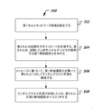
図3は、UEにおいて実装できる無線通信方法300のフローチャートである。方法300のステップ302において、第1セルとネットワーク接続を確立する。方法300のステップ304において、第2セルの起動を示すメッセージを受信する。第2セルは、起動したときモバイルデバイスが用いる第1帯域幅部分を有する。第2セルはさらに、第2帯域幅部分を有する。方法300のステップ306において、受信したメッセージに基づき、第1帯域幅部分を用いて第2セルに対してランダムアクセスプロシジャを実施する。方法300のステップ308において、ランダムアクセスプロシジャが失敗したとき、第2セルの第2帯域幅部分へスイッチする。
FIG. 3 is a flowchart of a
実施形態において、第1セルは例えばUEにとってのプライマリセル(PCell)である。UEはまず自身のPCellと接続を確立する。次にベースステーションからダウンリンク制御情報(DCI)を受信して、セカンダリセル(SCell)を起動する。SCellは、起動前に事前構成された第1有効BWPを有する。UEは、SCellが起動したとき、別の起動を実施することなく第1有効BWPを用いることができる。SCellは、高次レイヤが事前構成可能またはプロトコルにおいて指定可能なデフォルトBWPを有する。UEは次に、ランダムアクセス(RA)/ランダムアクセスチャネル(RACH)プロシジャを開始して、第1有効BWPを用いてSCellを起動する。RAプロシジャが失敗すると、UEはSCellのデフォルトBWPへスイッチし、ベースステーションから別のメッセージを待機する。 In an embodiment, the first cell is, for example, a primary cell (PCell) for the UE. The UE first establishes a connection with its PCell. Next, the downlink control information (DCI) is received from the base station, and the secondary cell (SCell) is activated. The SCell has a preconfigured first effective BWP prior to activation. When the SCell is started, the UE can use the first effective BWP without performing another start. The SCell has a default BWP where the higher layers can be preconfigured or specified in the protocol. The UE then initiates a random access (RA) / random access channel (RACH) procedure to activate the SCell with the first enabled BWP. If the RA procedure fails, the UE switches to SCell's default BWP and waits for another message from the base station.
図4は、UEにおいて実装できる無線通信方法400の別フローチャートである。方法400のステップ402において、セルとネットワーク接続を確立する。方法400のステップ404において、第1帯域幅部分を用いて、セルの通信を実施する。方法400のステップ406において、ネットワーク異常が発生した後、サービス提供セルの第2帯域幅部分を用いて、その後の通信を実施する。
FIG. 4 is another flowchart of the
実施形態において、UEはまずセルとネットワーク接続を確立する。UEは有効BWPを用いて、セルの通信を実施する。有効BWPは例えば、PCellの初期有効BWPまたはSCellの第1有効BWPである。有効BWPは、セル起動後にベースステーションが有効化した別BWPであってもよい。ただしネットワークイベントが発生した場合、UEは第2BWPへ自動的にスイッチする。第2BWPは例えば、サービス提供セルの有効BWPである。例えば第2BWPは、PCellの初期有効BWP、またはSCellの第1有効BWPである。第2BWPは、セルのために構成したデフォルトBWP、またはUEのセルの別の有効BWPであってもよい。 In an embodiment, the UE first establishes a network connection with the cell. The UE uses the effective BWP to carry out cell communication. The effective BWP is, for example, the initial effective BWP of PCell or the first effective BWP of SCell. The effective BWP may be another BWP activated by the base station after the cell is started. However, when a network event occurs, the UE automatically switches to the second BWP. The second BWP is, for example, an effective BWP of the service providing cell. For example, the second BWP is the initial effective BWP of PCell or the first effective BWP of SCell. The second BWP may be the default BWP configured for the cell, or another valid BWP in the UE cell.
図5は、ベースステーションにおいて実装できる無線通信方法500のフローチャートである。方法500のステップ502において、セルの第1帯域幅部分を用いて、モバイルデバイスとセルとの間でネットワーク接続を確立する。方法500のステップ504において、ネットワーク異常が検出されると、サービス提供セルの第2帯域幅部分を用いて、モバイルデバイスと送受信する。
FIG. 5 is a flowchart of a
実施形態において、ベースステーションはまず、有効BWPを用いて、UEとセルとの間でネットワーク接続を確立する。有効BWPは例えば、PCellの初期有効BWPまたはSCellの第1有効BWPである。有効BWPは、セル起動後にベースステーションが有効化した別BWPであってもよい。ベースステーションは次に、ネットワークイベントが発生したことを検出したとき、サービス提供セルの第2BWPへスイッチする。第2BWPは例えば、PCellの初期有効BWP、またはSCellの第1有効BWPである。第2BWPは、セルのために構成したデフォルトBWP、またはUEの別のサービス提供セルの別の有効BWPであってもよい。 In an embodiment, the base station first uses a valid BWP to establish a network connection between the UE and the cell. The effective BWP is, for example, the initial effective BWP of PCell or the first effective BWP of SCell. The effective BWP may be another BWP activated by the base station after the cell is started. The base station then switches to the second BWP of the service providing cell when it detects that a network event has occurred. The second BWP is, for example, the initial effective BWP of PCell or the first effective BWP of SCell. The second BWP may be the default BWP configured for the cell, or another valid BWP in another service providing cell of the UE.
以下の実施形態において、技術の詳細をさらに説明する。各実施形態において、UEはプライマリセル(セルA)と接続を確立する。セルAは以下の3つのBWPを有する:p−1、p−2、p−3。p−1はデフォルトBWPであり、p−2は初期有効BWPである。セルAが通信するために用いる現在の有効BWPは、p−2である。ネットワークトラフィックが増加すると、ベースステーションは計測レポートに基づき、UEのためにセカンダリセル(セルB)を追加することを決定する。セルAとセルBは、異なるタイミングアドバンスグループ(TAG)に属する。セルBは以下の4つのBWPを有する:s−1、s−2、s−3、s−4。s−3は第1有効BWPであり、s−1はデフォルトBWPである。 The details of the technique will be further described in the following embodiments. In each embodiment, the UE establishes a connection with the primary cell (cell A). Cell A has the following three BWPs: p-1, p-2, p-3. p-1 is the default BWP and p-2 is the initial valid BWP. The current valid BWP used by cell A to communicate is p-2. As network traffic increases, the base station decides to add a secondary cell (cell B) for the UE based on the measurement report. Cell A and B belong to different Timing Advance Groups (TAGs). Cell B has the following four BWPs: s-1, s-2, s-3, s-4. s-3 is the first effective BWP and s-1 is the default BWP.
<実施形態1> <Embodiment 1>
本実施形態は、RACHプロシジャが失敗したときUEがBWPを管理するステップ例を示す。 The present embodiment shows a step example in which the UE manages the BWP when the RACH procedure fails.
ステップ11において、ベースステーションは、例えばUEが送信したバッファ状態レポート(BSR)などの情報に基づき、UEのためにセルBを起動することを決める。ベースステーションは、ダウンリンク制御メッセージ(例:DCIメッセージ)を送信してセルBを起動する。UEは、別の起動を実施することなく、第1有効BWP s−3を用いる。 In step 11, the base station decides to start cell B for the UE, for example, based on information such as a buffer status report (BSR) sent by the UE. The base station activates cell B by sending a downlink control message (eg, a DCI message). The UE uses the first effective BWP s-3 without performing another boot.
ステップ12において、ベースステーションは、物理ダウンリンク制御チャネル(PDCCH)上で、セルBがUEのためにRACHプロシジャを開始できることを通知する。実施例においてUEは、RACHプロシジャを開始できる。 In step 12, the base station notifies on the physical downlink control channel (PDCCH) that cell B can initiate a RACH procedure for the UE. In an embodiment, the UE can initiate a RACH procedure.
ステップ13において、UEはセルBのRACHプロシジャを実施する。ただし図6に示すように、ステップ602において、UEはRACHプロシジャ内でエラーを受け取る。UEは次に、ステップ604において、現在の有効BWP(例:s−3)から別のBWPへ自動的にスイッチする。この具体例において、UEはセルBのデフォルトBWPへスイッチする。UEは、高次レイヤに対して失敗を通知する。これは、セル(例:セルB)起動によってトリガされたRACH失敗の例である。RACHプロシジャは、例えばULデータ到着などの別タイプのイベントによってトリガすることもできる。 In step 13, the UE performs a RACH procedure in cell B. However, as shown in FIG. 6, in step 602, the UE receives an error in the RACH procedure. The UE then automatically switches from the currently active BWP (eg s-3) to another BWP in step 604. In this embodiment, the UE switches to the default BWP in cell B. The UE notifies the higher layer of the failure. This is an example of a RACH failure triggered by cell (eg cell B) startup. The RACH procedure can also be triggered by another type of event, for example UL data arrival.
ステップ14において、ベースステーションがRACH失敗を検出すると、ベースステーションはセルBを停止することができる。受信した計測レポートに基づき、別のセカンダリセルを起動することもできる。 In step 14, if the base station detects a RACH failure, the base station can stop cell B. It is also possible to start another secondary cell based on the received measurement report.
実施形態において、セルBと同じTAG内に別のセルが存在する場合、RACHプロシジャが失敗したとき、それらセルも自動的に、現在の有効BWPから、対応するデフォルトBWPまたは第1有効BWPへスイッチできる。 In the embodiment, if another cell exists in the same TAG as cell B, then when the RACH procedure fails, those cells also automatically switch from the current active BWP to the corresponding default BWP or first effective BWP. can.
上記ステップはセカンダリセルのRACH失敗を記載しているが、PCellまたはプライマリSCell(PSCell)のRACH失敗へ適用することもできる。 Although the above step describes the RACH failure of the secondary cell, it can also be applied to the RACH failure of the PCell or the primary SCell (PSCell).
<実施形態2>
<
本実施形態は、時間同期タイマ(TAT)が時間満了したとき、UEがBWPを管理するステップ例を示す。 The present embodiment shows an example of a step in which the UE manages the BWP when the time synchronization timer (TAT) expires.
ステップ21において、ベースステーションは、例えばUEが送信したBSRなどの情報に基づき、UEのためにセルBを起動することを決める。ベースステーションは、ダウンリンク制御メッセージ(例:メディアアクセス制御(MAC)制御エレメント(CE))を送信して、セルBを起動する。UEは別の起動を実施することなく、第1有効BWP s−3を用いる。 In step 21, the base station decides to activate cell B for the UE, for example, based on information such as the BSR transmitted by the UE. The base station launches cell B by sending a downlink control message (eg, a media access control (MAC) control element (CE)). The UE uses the first effective BWP s-3 without performing another boot.
ステップ22において、ベースステーションは、PDCCH上において、セルBがUEのためにRACHプロシジャを開始できることを通知する。実施例において、UEはRACHプロシジャを開始できる。 In step 22, the base station notifies on the PDCCH that cell B can initiate a RACH procedure for the UE. In an embodiment, the UE can initiate a RACH procedure.
ステップ23において、UEはセルBのRACHプロシジャを実施する。UEがランダムアクセス応答(RAR)を受信した後、UEはセルBが属するTAGの時間同期タイマ(TAT)を開始する。RACHプロシジャは成功して完了する。 In step 23, the UE performs a RACH procedure in cell B. After the UE receives the random access response (RAR), the UE starts the time synchronization timer (TAT) of the TAG to which cell B belongs. The RACH procedure is successful and complete.
ステップ24において、UEがセルBに対してしばらく通信を実施した後、ベースステーションはUEが送信したBSRなどの情報に基づき、UEがより広い周波数バンドで通信を実施できるように、有効BWPをs−4へスイッチする。UEは次に、ベースステーションの通知にしたがって、以後の送信においてs−4へスイッチする。 In step 24, after the UE communicates with cell B for a while, the base station sets an effective BWP so that the UE can communicate in a wider frequency band based on information such as the BSR transmitted by the UE. Switch to -4. The UE then switches to s-4 for subsequent transmissions, following the notification of the base station.
ステップ25において、図7に示すように、UEはセルBが属するTAGのTATが時間満了したことを検出する(ステップ702)。セルBの有効BWPはs−4なので、UEはステップ704において、s−4から別のBWPへ自動的にスイッチし、ベースステーションからさらなる指示を待機する。実施形態においてUEは、セルBのデフォルトBWP s−1へスイッチする。実施例において、UEはセルBの第1有効BWP s−3へスイッチする。 In step 25, as shown in FIG. 7, the UE detects that the TAT of the TAG to which cell B belongs has expired (step 702). Since the effective BWP of cell B is s-4, the UE automatically switches from s-4 to another BWP in step 704 and waits for further instructions from the base station. In the embodiment, the UE switches to the default BWP s-1 in cell B. In an embodiment, the UE switches to the first effective BWP s-3 in cell B.
実施形態において、ベースステーションは、トラッキングエリアコード(TAC)に基づき、TATを再開する。実施例において、セルBが属するTAGは、複数セルを含む。TATが時間満了すると、同じTAG内の複数のセルは、同じ動作を実施できる。例えば同じTAG内の全セルは、TATが時間満了したとき、後続通信において、有効BWPから各デフォルトBWPまたは第1有効BWPへスイッチできる。 In an embodiment, the base station restarts TAT based on the tracking area code (TAC). In the embodiment, the TAG to which the cell B belongs includes a plurality of cells. When the TAT expires, multiple cells in the same TAG can perform the same operation. For example, all cells in the same TAG can switch from a valid BWP to each default BWP or a first valid BWP in subsequent communication when the TAT expires.
上記ステップはセカンダリセルの動作を記載しているが、これはPCellやPSCellへ適用できる。 The above steps describe the operation of the secondary cell, which can be applied to PCell and PSCell.
<実施形態3> <Embodiment 3>
本実施形態は、スケジューリングリクエスト(SR)送信トライアルの最大個数を超過したときUEがBWPを管理するステップ例を示す。 The present embodiment shows a step example in which the UE manages the BWP when the maximum number of scheduling request (SR) transmission trials is exceeded.
ステップ31において、ベースステーションは、UEが送信したBSRなどの情報に基づき、UEのためにセルBを起動することを決める。ベースステーションは、ダウンリンク制御メッセージ(例:MAC CE)を送信して、セルBを起動する。UEは別の起動を実施することなく、第1有効BWP s−3を使用する。 In step 31, the base station decides to activate cell B for the UE based on information such as the BSR transmitted by the UE. The base station sends a downlink control message (eg MAC CE) to activate cell B. The UE uses the first effective BWP s-3 without performing another boot.
ステップ32において、ベースステーションは、PDCCH上において、セルBがRACHプロシジャをUEのために開始できることを通知する。実施例において、UEはRACHプロシジャを開始できる。 In step 32, the base station notifies on the PDCCH that cell B can initiate a RACH procedure for the UE. In an embodiment, the UE can initiate a RACH procedure.
ステップ33において、UEはセルBのRACHプロシジャを実施する。RACHプロシジャは成功して完了し、UEは第1有効BWP s−3を用いて、セルBの通信を実施する。 In step 33, the UE performs a RACH procedure in cell B. The RACH procedure is completed successfully, and the UE uses the first effective BWP s-3 to perform communication in cell B.
ステップ34において、UEはアップリンクデータを送信する必要がある。ただしUEが利用できるアップリンクリソースはない。したがってUEは、SRプロシジャを開始する。 In step 34, the UE needs to transmit uplink data. However, there are no uplink resources available to the UE. Therefore, the UE initiates the SR procedure.
ステップ35において、UEはSRを送信することを複数回試みる。図8に示すように、ステップ802においてSR送信トライアルの最大回数を超過した後、ステップ804において、UEはs−3から別のBWPへ自動的にスイッチする。この具体例においてはデフォルトBWP s−1へスイッチする。UEは次に、ステップ806において、別のBWPを用いて、セルBのSRまたはRACHプロシジャを実施する。 In step 35, the UE attempts to transmit the SR multiple times. As shown in FIG. 8, after exceeding the maximum number of SR transmission trials in step 802, the UE automatically switches from s-3 to another BWP in step 804. In this embodiment, the default BWP s-1 is switched. The UE then performs an SR or RACH procedure in cell B using another BWP in step 806.
ステップ36において、ベースステーションは、有効BWP s−3とデフォルトBWP s−1両方において、SRメッセージをモニタする。デフォルトBWPにおいてベースステーションがSRを検出すると、ベースステーションはこれにしたがってアップリンクリソースをスケジューリングする。 In step 36, the base station monitors SR messages on both the enabled BWP s-3 and the default BWP s-1. If the base station detects an SR in the default BWP, the base station schedules the uplink resources accordingly.
ケースによっては、UEがSRプロシジャを開始したとき、有効BWPはs−4である。UEがs−4におけるSR送信トライアルの最大回数を超過すると、s−4とは異なるBWPへ自動的にスイッチする。このBWPは上述のように、第1有効BWP s−3またはデフォルトBWP s−1である。 In some cases, the effective BWP is s-4 when the UE initiates the SR procedure. When the UE exceeds the maximum number of SR transmission trials in s-4, it automatically switches to a BWP different from s-4. This BWP is the first effective BWP s-3 or the default BWP s-1, as described above.
上記ステップはセカンダリセルの動作を記載しているが、これはPCellまたはPSCellにも適用できる。 The above steps describe the operation of the secondary cell, which can also be applied to PCell or PSCell.
<実施形態4> <Embodiment 4>
本実施形態は、有効BWPにおいてリソースがないとき、UEがBWPを管理するステップ例を示す。 The present embodiment shows a step example in which the UE manages the BWP when there are no resources in the effective BWP.
ステップ41において、ベースステーションは、UEが送信するBSRなどの情報に基づき、UEのためにセルBを起動することを決める。ベースステーションは、ダウンリンク制御メッセージ(例:MAC CE)を送信して、セルBを起動する。UEは別の起動を実施することなく、第1有効BWP s−3を用いる。 In step 41, the base station decides to activate cell B for the UE based on information such as the BSR transmitted by the UE. The base station sends a downlink control message (eg MAC CE) to activate cell B. The UE uses the first effective BWP s-3 without performing another boot.
ステップ42において、ベースステーションは、PDCCH上において、セルBがUEのためにRACHプロシジャを開始できることを通知する。実施例において、UEはRACHプロシジャを開始できる。ステップ902において、現在のBWP s−3内にRACHリソースがない場合、ステップ904において、UEはs−3ではないBWPへ自動的にスイッチする。この具体例においてはデフォルトBWP s−1へスイッチする。UEは次に、ステップ906において、デフォルトBWP s−1を用いてRACHプロシジャを実施する。
In step 42, the base station notifies on the PDCCH that cell B can initiate a RACH procedure for the UE. In an embodiment, the UE can initiate a RACH procedure. In
ステップ43において、UEはセルBのRACHプロシジャを実施する。RACHプロシジャは成功して完了し、UEは第1有効BWP s−3を用いてセルBの通信を実施する。 In step 43, the UE performs a RACH procedure in cell B. The RACH procedure is successfully completed and the UE performs communication in cell B using the first effective BWP s-3.
ステップ44において、UEはアップリンクデータを送信する必要がある。ただしUEが利用できるアップリンクリソースはない。したがってUEはSRプロシジャを開始する。図9に示すように、ステップ902において、現在のBWP内にSRリソースがないと判定すると、ステップ904において、UEはs−3ではないBWPへ自動的にスイッチする。この具体例においてはデフォルトBWP s−1へスイッチする。UEは次に、ステップ906において、デフォルトBWP s−1を用いて、セルBのSRまたはRACHプロシジャを実施する。
In step 44, the UE needs to transmit uplink data. However, there are no uplink resources available to the UE. Therefore, the UE starts the SR procedure. As shown in FIG. 9, if it is determined in
ステップ45において、ベースステーションは、セルBの有効BWP s−3がSRリソースを有していないことを検出する。ベースステーションはこれにしたがってデフォルトBWP s−1へスイッチし、UEのためのアップリンク通信をスケジュールする。 In step 45, the base station detects that the effective BWP s-3 in cell B does not have SR resources. The base station switches to the default BWP s-1 accordingly and schedules uplink communication for the UE.
実施形態において、UEがSRプロシジャを開始したとき、有効BWPはs−4である。s−4においてSRリソースがない場合、UEはs−4から別のBWPへ自動的にスイッチする。このBWPは例えば上述のように、第1有効BWP s−3、またはデフォルトBWP s−1である。 In an embodiment, the effective BWP is s-4 when the UE initiates the SR procedure. If there are no SR resources in s-4, the UE automatically switches from s-4 to another BWP. This BWP is, for example, the first effective BWP s-3, or the default BWP s-1, as described above.
実施形態において、デフォルトBWPまたは初期/第1BWPがSRリソースを有していない場合、セルBまたはUEはRACHプロシジャを直接開始できる。 In an embodiment, if the default BWP or initial / first BWP does not have SR resources, cell B or UE can start the RACH procedure directly.
上記ステップはセカンダリセルの動作を記載しているが、これはPCellやPSCellにも適用できる。 The above steps describe the operation of the secondary cell, which can also be applied to PCell and PSCell.
<実施形態5>
<
本実施形態は、ベースステーションがセルを複数回起動したとき、UEがBWPを管理するステップ例を示す。 The present embodiment shows a step example in which the UE manages the BWP when the base station starts the cell a plurality of times.
ステップ51において、ベースステーションは、UEが送信したBSRなどの情報に基づき、UEのためにセルBを起動することを決める。図10に示すように、ベースステーションはステップ1002において、ダウンリンク制御メッセージ(例:MAC CE)を送信して、セルBを起動する。セルBは、UEが別の起動なしで用いる第1有効BWP s−3を有する。 In step 51, the base station decides to activate cell B for the UE based on information such as the BSR transmitted by the UE. As shown in FIG. 10, in step 1002, the base station sends a downlink control message (eg, MAC CE) to activate cell B. Cell B has a first effective BWP s-3 that the UE uses without another activation.
ステップ52において、ベースステーションは、PDCCH上で、セルBがUEのためにRACHプロシジャを開始できることを通知する。実施例において、UEはRACHプロシジャを開始できる。 In step 52, the base station notifies on the PDCCH that cell B can initiate a RACH procedure for the UE. In an embodiment, the UE can initiate a RACH procedure.
ステップ53において、UEはセルBのRACHプロシジャを実施する。RACHプロシジャが成功して完了した後、UEはステップ1004において、第1有効BWP s−3を用いてセルBの通信を実施する。 In step 53, the UE performs a RACH procedure in cell B. After the RACH procedure is successfully completed, the UE performs communication in cell B using the first effective BWP s-3 in step 1004.
ステップ54において、セルBはネットワーク動作に基づき停止できる。例えばベースステーションは、UEがレポートしたBSRに基づきメッセージを送信して、セルBを停止する。UEは、停止タイマが時間満了したときも、そのようにすることを決定してもよい。 In step 54, cell B can be stopped based on network operation. For example, the base station stops cell B by sending a message based on the BSR reported by the UE. The UE may decide to do so when the stop timer expires.
ステップ55において、ベースステーションは、UEが送信したBSRなどの情報に基づき、UEのために再びセルBを起動する。UEはステップ1006において、別セルの現在の有効BWPからセルBのs−3へ自動的にスイッチする。実施形態において、DCIメッセージは、セルBが起動するとデフォルトBWP s−1を用いることを通知する。
In step 55, the base station reactivates cell B for the UE based on information such as the BSR transmitted by the UE. In
<実施形態6> <Embodiment 6>
本実施形態は、RACHプロシジャが失敗したとき、UEがBWPを管理するステップ例を示す。 The present embodiment shows a step example in which the UE manages the BWP when the RACH procedure fails.
ステップ61において、UEはセルAの通信を実施する。UEがアップリンクデータを送信する必要があるとき、アップリンクリソースがないことを検出する。UEは次に、RACHプロシジャを開始する。 In step 61, the UE performs communication in cell A. Detects the absence of uplink resources when the UE needs to send uplink data. The UE then initiates the RACH procedure.
ステップ62において、図11に示すように、UEはRACHプロシジャにおいてエラーを受け取る(ステップ1102)。通信に用いる有効BWPはp−2であり、UEはステップ1104において、別BWPへ自動的にスイッチする。実施形態において、UEはデフォルトBWP p−1へスイッチする。 In step 62, as shown in FIG. 11, the UE receives an error in the RACH procedure (step 1102). The effective BWP used for communication is p-2, and the UE automatically switches to another BWP in step 1104. In an embodiment, the UE switches to the default BWP p-1.
ステップ63において、UEは別BWP p−1を用いて、RRC再確立プロシジャを実施する(ステップ1106)。 In step 63, the UE performs an RRC reestablishment procedure using another BWP p-1 (step 1106).
<実施形態7> <Embodiment 7>
本実施形態は、ベースステーションからハンドオーバコマンドを受信したとき、UEがBWPを管理するステップ例を示す。 The present embodiment shows a step example in which the UE manages the BWP when a handover command is received from the base station.
ステップ71において、ベースステーションは、UEが送信したBSRなどの情報に基づき、UEのためにセルBを起動することを決める。ベースステーションは、ダウンリンク制御メッセージ(例:MAC CE)を送信して、セルBを起動する。UEは、別の起動を実施することなく、第1有効BWP s−3を用いる。 In step 71, the base station decides to start cell B for the UE based on information such as the BSR transmitted by the UE. The base station sends a downlink control message (eg MAC CE) to activate cell B. The UE uses the first effective BWP s-3 without performing another boot.
ステップ72において、ベースステーションは、PDCCH上において、セルBがUEのためにRACHプロシジャを開始できることを通知する。実施例において、UEはRACHプロシジャを開始できる。 In step 72, the base station notifies on the PDCCH that cell B can initiate a RACH procedure for the UE. In an embodiment, the UE can initiate a RACH procedure.
ステップ73において、UEはセルBのRACHプロシジャを実施する。RACHプロシジャは成功して完了し、UEは第1有効BWP s−3を用いて、セルBの通信を実施する。 In step 73, the UE performs a RACH procedure in cell B. The RACH procedure is completed successfully, and the UE uses the first effective BWP s-3 to perform communication in cell B.
ステップ74において、ベースステーションは、セルAの信号強度が悪化していることを検出する。ベースステーションは、セルBをセカンダリセルとして維持し、UEに対して、プライマリセルをセルAからセルCへスイッチするように指示するハンドオーバコマンドを送信する。 In step 74, the base station detects that the signal strength of cell A has deteriorated. The base station maintains cell B as a secondary cell and sends a handover command instructing the UE to switch the primary cell from cell A to cell C.
ステップ75において、図12に示すように、UEはベースステーションからハンドオーバコマンドを受信して、セルCへスイッチする(ステップ1202)。UEはステップ1204において、MACリセットプロシジャを実施する。UEはステップ1206において、セルAの有効BWPから別BWP(例えばセルCの初期有効BWPまたはデフォルトBWP)へ自動的にスイッチする。 In step 75, as shown in FIG. 12, the UE receives a handover command from the base station and switches to cell C (step 1202). The UE performs a MAC reset procedure in step 1204. In step 1206, the UE automatically switches from the valid BWP in cell A to another BWP (eg, the initial valid BWP in cell C or the default BWP).
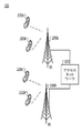
図13は、本技術の1以上の実施形態に係る技術を適用できる無線通信システムの例を示す。無線通信システム400は、1以上のベースステーション(BS)(1305a、1305b)、1以上の無線デバイス(1310a、1310b、1310c、1310d)、アクセスネットワーク1325を有する。ベースステーション1305aと1305bは、1以上の無線セクタにおいて、無線デバイス1310a、1310b、1310c、1310dに対して、無線サービスを提供できる。実施例において、ベースステーション1305aと1305bは、方向性アンテナを有し、これにより2以上の方向性ビームを生成して、複数のセクタにおける無線カバー範囲を提供する。
FIG. 13 shows an example of a wireless communication system to which the technology according to one or more embodiments of the present technology can be applied. The
アクセスネットワーク1325は、1以上のベースステーション1305a、1305bと通信できる。実施例において、アクセスネットワーク1325は、1以上のベースステーション1305aと1305bを有する。実施例において、アクセスネットワーク1325は、他の無線通信システムおよび優先通信システムとの接続を提供するコアネットワーク(図示せず)と通信する。コアネットワークは、サブスクライブする無線デバイス10a、1310b、1310c、1310dに関する情報を格納する1以上のサービスサブスクリプションデータベースを有する。第1ベースステーション1305aは、第1無線アクセス技術に基づき無線サービスを提供でき、第2ベースステーション1305bは、第2無線アクセス技術に基づき無線サービスを提供できる。ベースステーション1305aと1305bは、同じ場所に配置し、あるいは配置シナリオにしたがって分離して設置することができる。アクセスネットワーク1325は、複数の無線アクセス技術をサポートできる。
The access network 1325 can communicate with one or
実施例において、無線通信システムは、異なる無線技術を用いて、複数のネットワークを有することができる。デュアルモードまたはマルチモード無線デバイスは、異なる無線ネットワークに接続するために使用できる2以上の無線技術を有する。 In an embodiment, the wireless communication system can have multiple networks using different wireless technologies. Dual-mode or multi-mode wireless devices have two or more wireless technologies that can be used to connect to different wireless networks.
図14は、無線ステーションの一部のブロック図である。無線ステーション1405は例えばベースステーションや無線デバイス(あるいはUE)であり、本文書が提示する1以上の無線技術を実装するマイクロプロセッサなどのプロセッサ電子部品1410を備える。無線ステーション1405は、1以上の通信インターフェース(例えばアンテナ1420)上で無線信号を送信および/または受信するトランシーバ電子部品1415を備える。無線ステーション1405は、データを送受信するその他通信インターフェースを備えることもできる。無線ステーション1405は、データおよび/または命令などの情報を格納するように構成された1以上のメモリ(明示的には図示せず)を備える。実施例において、プロセッサ電子部品1410は、トランシーバ電子部品1415の少なくとも一部を含む。実施形態において、本技術、モジュール、または機能のうち少なくとも一部は無線ステーション1405を用いて実装できる。
FIG. 14 is a block diagram of a part of the wireless station. The radio station 1405 is, for example, a base station or a radio device (or UE) and comprises a processor
したがって、本特許文書は帯域幅部分の管理に関する技術を記載していることは明らかである。本技術により、UEはまたはベースステーションは、ネットワークイベントが発生またはこれを検出したとき、現在の有効BWPとは異なるBWPへ自動的にスイッチして、セルの後続通信を実施できる。これにより、BWPの変更が望ましいとき、信号オーバヘッドまたは遅延を最小化できる。 Therefore, it is clear that this patent document describes techniques for managing bandwidth portions. According to the present technology, when a network event occurs or is detected by the UE or the base station, the UE or the base station can automatically switch to a BWP different from the currently valid BWP to carry out subsequent communication of the cell. This allows signal overhead or delay to be minimized when BWP changes are desired.
上記説明から、本開示技術の特定の実施形態は説明目的のために記載したものであり、本発明の範囲から逸脱することなく様々な変形が可能であることを、理解されたい。したがって本開示技術は、特許請求範囲以外によって限定されることはない。 From the above description, it should be understood that the specific embodiments of the disclosed techniques have been described for explanatory purposes and that various modifications are possible without departing from the scope of the present invention. Therefore, the disclosed technology is not limited to anything other than the claims.
開示されたおよび他の実施形態、モジュール、並びに本文書に記載した機能的動作は、本文書に開示されている構造およびそれらの構造的等価物またはそれらの一つ以上の組み合わせを含む、デジタル電子回路において、またはコンピュータソフトウェア、ファームウェア、若しくはハードウェアにおいて、実施することができる。開示されたおよび他の実施形態は、一つ以上のコンピュータプログラム製品、すなわち、データ処理装置によって実行するためのまたはデータ処理装置の動作を制御するためにコンピュータ可読媒体上で符号化されたコンピュータプログラム命令の一つ以上のモジュールとして、実施することができる。コンピュータ可読媒体は、機械可読ストレージデバイス、機械可読ストレージ基板、メモリデバイス、機械可読伝播信号を有効にする物質の組成物、またはそれらの一つ以上の組み合わせとすることができる。用語「データ処理装置」は、プログラム可能なプロセッサ、コンピュータ、または複数のプロセッサ若しくはコンピュータを例として含む、データを処理するためのあらゆる装置、デバイス、および機械を包含する。装置は、ハードウェアの他に、当該コンピュータプログラムの実行環境を作り出すコード、例えば、プロセッサファームウェア、プロトコルスタック、データベース管理システム、オペレーティングシステム、またはこれらの一つ以上の組み合わせを構成するコードを含み得る。伝播信号とは人工的に生成された信号であり、例えば、好適な受信機装置に送信するため情報を符号化するように生成されている、機械が生成した電気、光学、または電磁信号である。 The disclosed and other embodiments, modules, and functional operations described herein include the structures disclosed in this document and their structural equivalents or one or more combinations thereof. It can be done in a circuit or in computer software, firmware, or hardware. The disclosed and other embodiments are one or more computer program products, i.e., computer programs encoded on a computer-readable medium to be executed by a data processor or to control the operation of the data processor. It can be implemented as one or more modules of instructions. The computer-readable medium can be a machine-readable storage device, a machine-readable storage substrate, a memory device, a composition of substances that enable a machine-readable propagation signal, or a combination thereof. The term "data processor" includes any device, device, and machine for processing data, including programmable processors, computers, or, by way of example, multiple processors or computers. In addition to hardware, the device may include code that creates the execution environment for the computer program, such as processor firmware, a protocol stack, a database management system, an operating system, or any combination thereof. A propagating signal is an artificially generated signal, eg, a machine-generated electrical, optical, or electromagnetic signal that is generated to encode information for transmission to a suitable receiver device. ..
コンピュータプログラム(プログラム、ソフトウェア、ソフトウェアアプリケーション、スクリプト、またはコードとしても知られる)は、コンパイラ型言語またはインタープリタ型言語を含む任意の形態のプログラミング言語で記述することができ、スタンドアロンプログラムとして、またはモジュール、コンポーネント、サブルーチン、若しくはコンピュータ環境での使用に適した他のユニットとしてを含め、任意の形態で展開することができる。コンピュータプログラムは、ファイルシステムにおけるファイルに必ずしも対応していない。プログラムは、他のプログラム若しくはデータ(例えば、マークアップ言語文書に格納された一つ以上のスクリプト)を保持するファイルの一部に、当該プログラム専用の単一のファイルに、または、複数の連携したファイル(例えば、一つ若しくは複数のモジュール、サブプログラム、若しくはコード部分を格納するファイル)に、格納することができる。コンピュータプログラムは、一つのコンピュータ上で、または、一つの場所に配置されているか若しくは通信ネットワークによって相互接続された複数の場所にわたって分散されている複数のコンピュータ上で実行されるように、配備することができる。 Computer programs (also known as programs, software, software applications, scripts, or code) can be written in any form of programming language, including compiled or interpreted languages, either as standalone programs or as modules. It can be deployed in any form, including as a component, subroutine, or other unit suitable for use in a computer environment. Computer programs do not always support files in the file system. A program may be part of a file that holds another program or data (eg, one or more scripts stored in a markup language document), a single file dedicated to that program, or multiple links. It can be stored in a file (for example, a file that stores one or more modules, subprograms, or code parts). Computer programs should be deployed to run on one computer or on multiple computers located in one location or distributed across multiple locations interconnected by communication networks. Can be done.
本文書に記載した処理および論理フローは、入力データに対して演算を行い出力を生成することで機能を果たす一つ以上のコンピュータプログラムを実行する、一つ以上のプログラム可能なプロセッサによって実行できる。処理および論理フローは専用論理回路、例えばFPGA(フィールドプログラマブルゲートアレイ)またはASIC(特定用途向け集積回路)よっても実行可能であり、装置は上記した専用論理回路として実装可能である。 The processing and logical flows described in this document can be executed by one or more programmable processors that execute one or more computer programs that perform functions by performing operations on input data and generating output. The processing and logic flow can also be executed by a dedicated logic circuit, such as FPGA (Field Programmable Gate Array) or ASIC (Application Specific Integrated Circuit), and the device can be implemented as the dedicated logic circuit described above.
コンピュータプログラムの実行に適したプロセッサとしては、例として、汎用マイクロプロセッサおよび専用マイクロプロセッサの両方、並びに、任意の種類のデジタルコンピュータの任意の一つ以上のプロセッサを挙げることができる。一般に、プロセッサは、読み出し専用メモリまたはランダムアクセスメモリまたは両方から、命令およびデータを受信するものである。コンピュータの本質的な要素は、命令を実行するためのプロセッサ、並びに、命令およびデータを格納するための一つ以上のメモリデバイスである。一般に、コンピュータはまた、データを格納するための一つ以上のマスストレージデバイス、例えば磁気ディスク、光磁気ディスク、若しくは光学ディスクを含むか、または、そこからデータ受信する、若しくはそこからデータを転送する、若しくはその両方を行うよう作動するように結合されるものである。しかしながら、コンピュータは必ずしもかかるデバイスを有さない。コンピュータプログラム命令およびデータの格納に適したコンピュータ可読媒体としては、半導体メモリデバイス、例えばEPROM、EEPROM、およびフラッシュメモリデバイス;磁気ディスク、例えば内部ハードディスクまたはリムーバブルディスク;光磁気ディスク;並びにCD ROMおよびDVD-ROMディスクを例として含む、あらゆる形態の不揮発性メモリ、媒体、およびメモリデバイスが挙げられる。プロセッサおよびメモリは、専用論理回路によって補完すること、または専用論理回路に組み込むことができる。 Suitable processors for executing computer programs include, for example, both general purpose and dedicated microprocessors, as well as any one or more processors of any type of digital computer. In general, a processor receives instructions and data from read-only memory, random access memory, or both. An essential element of a computer is a processor for executing instructions and one or more memory devices for storing instructions and data. In general, a computer also includes or receives data from or transfers data from one or more mass storage devices for storing data, such as magnetic disks, magneto-optical disks, or optical disks. , Or both, are coupled to work. However, computers do not necessarily have such devices. Computer-readable media suitable for storing computer program instructions and data include semiconductor memory devices such as EPROM, EEPROM, and flash memory devices; magnetic disks such as internal hard disks or removable disks; magneto-optical disks; and CD ROMs and DVDs- Examples include all forms of non-volatile memory, media, and memory devices, including ROM disks. The processor and memory can be complemented by a dedicated logic circuit or incorporated into a dedicated logic circuit.
本文書は多くの詳細を含むが、それらは特許請求されているまたは特許請求され得る発明の範囲を限定するものとしてではなく、特定の実施形態に特有の特徴の記載として解釈されるべきである。本文書において別々の実施形態の文脈で記載されている特定の特徴を、単一の実施形態として組み合わせて実施することも可能である。逆に、単一の実施形態の文脈で記載されている様々な特徴を、複数の実施形態において個別にまたは任意の好適な下位組み合わせで実施することもできる。更に、特徴は特定の組み合わせで機能するものとして上記されている場合があり、そのように当初特許請求されている場合さえあるが、特許請求される組み合わせにある一つ以上の特徴を、場合によってはその組み合わせから削除することができ、その特許請求される組み合わせは、下位組み合わせまたは下位組み合わせの変形を対象としてもよい。 Although this document contains many details, they should be construed as a statement of features specific to a particular embodiment, not as a limitation of the claims or claims of the invention. .. It is also possible to combine certain features described in the context of different embodiments in this document as a single embodiment. Conversely, the various features described in the context of a single embodiment can be implemented individually or in any suitable subcombination in multiple embodiments. Further, the features may be described above as functioning in a particular combination, and may even be initially patented as such, but in some cases one or more features in the claimed combination. Can be removed from the combination, and the claimed combination may be subject to subcombination or modification of the subcombination.
同様に、図面において動作が特定の順序で描写されているが、このことは、望ましい結果を達成するために、そのような動作を示された特定の順序で若しくは連続した順序で実行することまたは図示された全ての動作を実行することが必要になるものと理解されるべきではない。さらに、本特許文書が記載する実施形態の様々なシステムコンポーネントが分離していることは、全実施形態においてそのような分離が必要であると解釈すべきではない。 Similarly, the movements are depicted in the drawings in a particular order, which means that such movements may be performed in the particular order shown or in a contiguous order in order to achieve the desired result. It should not be understood that it is necessary to perform all the actions shown. Moreover, the separation of the various system components of the embodiments described in this patent document should not be construed as requiring such separation in all embodiments.
数件の例および実装形態のみが開示されている。開示されている内容に基づき、記載された例および実装形態並びに他の実装形態に対して、変形、修正、改良を行うことができる。 Only a few examples and implementations are disclosed. Based on the disclosed contents, modifications, modifications, and improvements can be made to the described examples and implementation forms as well as other implementation forms.
Claims (9)
ユーザ機器(UE)によって、サービス提供セルの第1帯域幅部分を用いて前記サービス提供セルの通信を実施するステップであって、前記第1帯域幅部分は物理リソースブロックの第1隣接サブセットを表す、ステップ;
前記UEによって、ランダムアクセスプロシジャを開始するために利用できるように構成されたランダムアクセスリソースがないと判定したとき、物理リソースブロックの第2隣接サブセットを表す前記サービス提供セルの第2帯域幅部分へスイッチしてその後の通信を実施するステップ;
を有する
ことを特徴とする方法。 It ’s a wireless communication method.
The step of performing communication of the service providing cell by the user equipment (UE) using the first bandwidth portion of the service providing cell, wherein the first bandwidth portion represents a first adjacent subset of physical resource blocks. , Step;
When the UE determines that there are no random access resources configured to be available to initiate a random access procedure, it goes to the second bandwidth portion of the service providing cell that represents the second adjacent subset of physical resource blocks. Steps to switch and perform subsequent communication;
A method characterized by having.
ことを特徴とする請求項1記載の方法。 The method according to claim 1, wherein the second bandwidth portion is an initial bandwidth portion of the service providing cell.
ことを特徴とする請求項1記載の方法。 The method according to claim 1, wherein the second bandwidth portion is preconfigured.
プロセッサ、
前記プロセッサが実行することにより前記プロセッサに方法を実施させるプロセッサ実行可能コードを格納するメモリ、
を備え、
前記方法は、
サービス提供セルの第1帯域幅部分を用いて前記サービス提供セルの通信を実施するステップであって、前記第1帯域幅部分は物理リソースブロックの第1隣接サブセットを表す、ステップ;
ランダムアクセスプロシジャを開始するために利用できるように構成されたランダムアクセスリソースがないと判定したとき、物理リソースブロックの第2隣接サブセットを表す前記サービス提供セルの第2帯域幅部分へスイッチしてその後の通信を実施するステップ;
を有する
ことを特徴とする無線通信装置。 It ’s a wireless communication device,
Processor,
A memory that stores processor executable code that causes the processor to perform a method by executing the processor.
With
The method is
A step of performing communication of the service providing cell using the first bandwidth portion of the service providing cell, wherein the first bandwidth portion represents a first adjacent subset of physical resource blocks;
When it determines that there are no random access resources configured to be available to start a random access procedure, it switches to the second bandwidth portion of the service-providing cell that represents the second adjacent subset of physical resource blocks and then. Steps to carry out communication;
A wireless communication device characterized by having.
前記方法は、
ユーザ機器(UE)によって、サービス提供セルの第1帯域幅部分を用いて前記サービス提供セルの通信を実施するステップであって、前記第1帯域幅部分は物理リソースブロックの第1隣接サブセットを表す、ステップ;
前記UEによって、ランダムアクセスプロシジャを開始するために利用できるように構成されたランダムアクセスリソースがないと判定したとき、物理リソースブロックの第2隣接サブセットを表す前記サービス提供セルの第2帯域幅部分へスイッチしてその後の通信を実施するステップ;
を有する
ことを特徴とする記憶媒体。 A storage medium that stores code that is executed by a processor to cause the processor to perform a method.
The method is
The step of performing communication of the service providing cell by the user equipment (UE) using the first bandwidth portion of the service providing cell, wherein the first bandwidth portion represents a first adjacent subset of physical resource blocks. , Step;
When the UE determines that there are no random access resources configured to be available to initiate a random access procedure, it goes to the second bandwidth portion of the service providing cell that represents the second adjacent subset of physical resource blocks. Steps to switch and perform subsequent communication;
A storage medium characterized by having.
ことを特徴とする請求項4記載の装置。 The device according to claim 4, wherein the second bandwidth portion is an initial bandwidth portion of the service providing cell.
ことを特徴とする請求項4記載の装置。 The device according to claim 4, wherein the second bandwidth portion is preconfigured.
ことを特徴とする請求項5記載の記憶媒体。 The storage medium according to claim 5, wherein the second bandwidth portion is an initial bandwidth portion of the service providing cell.
ことを特徴とする請求項5記載の記憶媒体。 The storage medium according to claim 5, wherein the second bandwidth portion is preconfigured.
Applications Claiming Priority (1)
| Application Number | Priority Date | Filing Date | Title |
|---|---|---|---|
| PCT/CN2017/111405 WO2019095222A1 (en) | 2017-11-16 | 2017-11-16 | Method and apparatus for managing bandwidth parts |
Publications (3)
| Publication Number | Publication Date |
|---|---|
| JP2020523886A JP2020523886A (en) | 2020-08-06 |
| JP2020523886A5 JP2020523886A5 (en) | 2020-09-17 |
| JP6915103B2 true JP6915103B2 (en) | 2021-08-04 |
Family
ID=66539242
Family Applications (1)
| Application Number | Title | Priority Date | Filing Date |
|---|---|---|---|
| JP2019569300A Active JP6915103B2 (en) | 2017-11-16 | 2017-11-16 | How and equipment to manage Bandwidth Parts |
Country Status (8)
| Country | Link |
|---|---|
| US (1) | US20200045702A1 (en) |
| EP (2) | EP4287752A1 (en) |
| JP (1) | JP6915103B2 (en) |
| KR (1) | KR102303964B1 (en) |
| CN (1) | CN110892764B (en) |
| DK (1) | DK3639585T3 (en) |
| PT (1) | PT3639585T (en) |
| WO (1) | WO2019095222A1 (en) |
Families Citing this family (13)
| Publication number | Priority date | Publication date | Assignee | Title |
|---|---|---|---|---|
| CN116321510A (en) * | 2017-11-17 | 2023-06-23 | 华为技术有限公司 | Method for random access, terminal device and network device |
| EP3711427A1 (en) * | 2017-11-18 | 2020-09-23 | Lenovo (Singapore) Pte. Ltd. | Random access configuration |
| US11496937B2 (en) * | 2017-11-24 | 2022-11-08 | FG Innovation Company Limited | Methods and related devices for handling random access procedure in bandwidth part switching operation |
| US11006442B2 (en) * | 2018-02-13 | 2021-05-11 | Mediatek Singapore Pte. Ltd. | Method and apparatus for bandwidth part switch operations in mobile communications |
| WO2019158998A2 (en) * | 2018-02-14 | 2019-08-22 | Lenovo (Singapore) Ltd. | Determining linked bandwidth parts |
| DK3753374T3 (en) * | 2018-02-15 | 2021-09-06 | Ericsson Telefon Ab L M | Bandwidth features for dormant and idle modes |
| KR102512908B1 (en) * | 2018-03-29 | 2023-03-22 | 베이징 시아오미 모바일 소프트웨어 컴퍼니 리미티드 | Method and device for reporting information, method and device for operation based on bandwidth part |
| US11350477B2 (en) * | 2019-03-29 | 2022-05-31 | Qualcomm Incorporated | Control signaling after primary cell link failure |
| CN113940115A (en) * | 2019-04-01 | 2022-01-14 | 苹果公司 | Delay and interrupt configuration for bandwidth partial handover |
| WO2021075712A1 (en) * | 2019-10-17 | 2021-04-22 | 엘지전자 주식회사 | Bwp activation method for terminal |
| US20220046612A1 (en) * | 2020-08-06 | 2022-02-10 | Qualcomm Incorporated | BANDWIDTH PART (BWP) CONFIGURATION WITH A SHARED PARTIAL CONFIGURATION FOR NON-TERRESTRIAL NETWORKS (NTNs) |
| WO2023108482A1 (en) * | 2021-12-15 | 2023-06-22 | Nokia Shanghai Bell Co., Ltd. | Bandwidth part selection for random access procedures |
| WO2023207805A1 (en) * | 2022-04-27 | 2023-11-02 | Mediatek Inc. | Method and apparatus for efficient spectrum aggregation with a multi-cluster bwp in mobile communications |
Family Cites Families (12)
| Publication number | Priority date | Publication date | Assignee | Title |
|---|---|---|---|---|
| US7340759B1 (en) * | 2000-11-10 | 2008-03-04 | Scientific-Atlanta, Inc. | Systems and methods for adaptive pricing in a digital broadband delivery system |
| US20090093255A1 (en) * | 2007-10-05 | 2009-04-09 | Qualcomm Incorporated | Adjusting multi-carrier allocation in wireless networks |
| CN101860929B (en) * | 2009-04-13 | 2013-06-12 | 中兴通讯股份有限公司 | Inter-base station switching method |
| US8599708B2 (en) * | 2010-01-14 | 2013-12-03 | Qualcomm Incorporated | Channel feedback based on reference signal |
| WO2011139053A2 (en) * | 2010-05-01 | 2011-11-10 | Pantech Co., Ltd. | Apparatus and method for transmitting sounding reference signal in wireless communication system supporting multiple component carriers |
| CN102244559A (en) * | 2010-05-12 | 2011-11-16 | 华为技术有限公司 | Method and device for sending and receiving precoding information |
| CN102932952B (en) * | 2011-08-12 | 2016-06-08 | 上海贝尔股份有限公司 | A kind of method and apparatus carrying out Stochastic accessing |
| US9755813B2 (en) * | 2012-03-15 | 2017-09-05 | Lg Electronics Inc. | Method and apparatus for controlling deactivation timer of cell included in tag |
| US10143013B2 (en) * | 2015-10-02 | 2018-11-27 | Sony Mobile Communications Inc. | Apparatus, systems and methods for user equipment (UE) coverage enhancement level definition, selection and allocation |
| CN109076473B (en) * | 2016-03-30 | 2021-03-30 | 夏普株式会社 | Terminal device, base station device, communication method, and control method |
| KR102218369B1 (en) * | 2016-10-11 | 2021-02-22 | 텔레호낙티에볼라게트 엘엠 에릭슨(피유비엘) | Methods and apparatuses for adapting random access configuration to control interruptions associated with SRS carrier based switching |
| EP3591887B1 (en) * | 2017-11-09 | 2022-02-09 | Beijing Xiaomi Mobile Software Co., Ltd. | Methods and apparatuses for communications based on wireless device capabilities |
-
2017
- 2017-11-16 WO PCT/CN2017/111405 patent/WO2019095222A1/en unknown
- 2017-11-16 PT PT179318472T patent/PT3639585T/en unknown
- 2017-11-16 DK DK17931847.2T patent/DK3639585T3/en active
- 2017-11-16 JP JP2019569300A patent/JP6915103B2/en active Active
- 2017-11-16 KR KR1020207001188A patent/KR102303964B1/en active IP Right Grant
- 2017-11-16 EP EP23190537.3A patent/EP4287752A1/en active Pending
- 2017-11-16 EP EP17931847.2A patent/EP3639585B1/en active Active
- 2017-11-16 CN CN201780093267.1A patent/CN110892764B/en active Active
-
2019
- 2019-10-08 US US16/596,752 patent/US20200045702A1/en not_active Abandoned
Also Published As
| Publication number | Publication date |
|---|---|
| EP3639585A1 (en) | 2020-04-22 |
| KR102303964B1 (en) | 2021-09-27 |
| DK3639585T3 (en) | 2023-09-25 |
| JP2020523886A (en) | 2020-08-06 |
| CN110892764B (en) | 2022-04-15 |
| EP4287752A1 (en) | 2023-12-06 |
| US20200045702A1 (en) | 2020-02-06 |
| KR20200015762A (en) | 2020-02-12 |
| EP3639585A4 (en) | 2020-06-24 |
| EP3639585B1 (en) | 2023-08-23 |
| WO2019095222A1 (en) | 2019-05-23 |
| PT3639585T (en) | 2023-09-19 |
| CN110892764A (en) | 2020-03-17 |
Similar Documents
| Publication | Publication Date | Title |
|---|---|---|
| JP6915103B2 (en) | How and equipment to manage Bandwidth Parts | |
| US20220078638A1 (en) | Csi transmission with multiple bandwidth parts | |
| CN111344980B (en) | Radio resource allocation synchronization | |
| US20220095365A1 (en) | Configured Grant and Dynamic Grant Transmission | |
| US20220217762A1 (en) | Activation and Deactivation of Configured Grant | |
| JP6865849B2 (en) | Radio access network notification area update failure | |
| CN113455049B (en) | Primary cell change | |
| EP3589067A1 (en) | Packet duplication control | |
| JP2022531228A (en) | Multiple SPS and preconfigured grant configurations | |
| RU2726873C1 (en) | User equipment, base station and wireless communication system | |
| CA3094877A1 (en) | Communication channel failure detection and recovery | |
| JP7442156B2 (en) | Subsequent data information for small data transmissions | |
| JP2022521821A (en) | Cell information for access control | |
| CA3104643A1 (en) | Downlink reception and beam management | |
| JP2023508232A (en) | Small Data Transmission (SDT) | |
| JP2017507596A (en) | Systems, methods and devices for opportunistic networking | |
| JP2010263629A (en) | Handover method, mobile terminal and base station | |
| RU2745900C2 (en) | Terminal device, base station apparatus, method of connection and integrated circuit | |
| KR20190037049A (en) | Apparatus and Methods of RRC signaling to support Wide Bandwidth | |
| US9781720B2 (en) | Component carrier (de)activation in communication systems using carrier aggregation | |
| US20230328672A1 (en) | Cell synchronization and timing management in a wireless network | |
| US20230171590A1 (en) | Capability information for a user equipment | |
| WO2024029425A1 (en) | Base station and communication system | |
| WO2023204186A1 (en) | Communication system |
Legal Events
| Date | Code | Title | Description |
|---|---|---|---|
| A521 | Request for written amendment filed |
Free format text: JAPANESE INTERMEDIATE CODE: A523 Effective date: 20191213 |
|
| A621 | Written request for application examination |
Free format text: JAPANESE INTERMEDIATE CODE: A621 Effective date: 20191213 |
|
| A977 | Report on retrieval |
Free format text: JAPANESE INTERMEDIATE CODE: A971007 Effective date: 20201215 |
|
| A131 | Notification of reasons for refusal |
Free format text: JAPANESE INTERMEDIATE CODE: A131 Effective date: 20210105 |
|
| A521 | Request for written amendment filed |
Free format text: JAPANESE INTERMEDIATE CODE: A523 Effective date: 20210126 |
|
| TRDD | Decision of grant or rejection written | ||
| A01 | Written decision to grant a patent or to grant a registration (utility model) |
Free format text: JAPANESE INTERMEDIATE CODE: A01 Effective date: 20210629 |
|
| A61 | First payment of annual fees (during grant procedure) |
Free format text: JAPANESE INTERMEDIATE CODE: A61 Effective date: 20210714 |
|
| R150 | Certificate of patent or registration of utility model |
Ref document number: 6915103 Country of ref document: JP Free format text: JAPANESE INTERMEDIATE CODE: R150 |