JP6914927B2 - Coatings that reduce NOx and methods for reducing NOx by the coating - Google Patents
Coatings that reduce NOx and methods for reducing NOx by the coating Download PDFInfo
- Publication number
- JP6914927B2 JP6914927B2 JP2018520472A JP2018520472A JP6914927B2 JP 6914927 B2 JP6914927 B2 JP 6914927B2 JP 2018520472 A JP2018520472 A JP 2018520472A JP 2018520472 A JP2018520472 A JP 2018520472A JP 6914927 B2 JP6914927 B2 JP 6914927B2
- Authority
- JP
- Japan
- Prior art keywords
- coating layer
- coating
- nox
- layer
- laminated structure
- Prior art date
- Legal status (The legal status is an assumption and is not a legal conclusion. Google has not performed a legal analysis and makes no representation as to the accuracy of the status listed.)
- Active
Links
- 238000000576 coating method Methods 0.000 title claims description 132
- 239000011248 coating agent Substances 0.000 title claims description 124
- 238000000034 method Methods 0.000 title description 33
- 230000001603 reducing effect Effects 0.000 title description 8
- 239000011247 coating layer Substances 0.000 claims description 133
- 239000010410 layer Substances 0.000 claims description 133
- 230000001699 photocatalysis Effects 0.000 claims description 50
- 239000000758 substrate Substances 0.000 claims description 47
- 230000009467 reduction Effects 0.000 claims description 43
- GWEVSGVZZGPLCZ-UHFFFAOYSA-N Titan oxide Chemical compound O=[Ti]=O GWEVSGVZZGPLCZ-UHFFFAOYSA-N 0.000 claims description 37
- 230000003647 oxidation Effects 0.000 claims description 23
- 238000007254 oxidation reaction Methods 0.000 claims description 23
- 239000003973 paint Substances 0.000 claims description 17
- 239000004408 titanium dioxide Substances 0.000 claims description 17
- 230000002195 synergetic effect Effects 0.000 claims description 8
- 239000002245 particle Substances 0.000 claims description 7
- -1 masonry Substances 0.000 claims description 5
- 229920003023 plastic Polymers 0.000 claims description 5
- 239000010440 gypsum Substances 0.000 claims description 4
- 229910052602 gypsum Inorganic materials 0.000 claims description 4
- 229910052751 metal Inorganic materials 0.000 claims description 4
- 239000002184 metal Substances 0.000 claims description 4
- 239000000123 paper Substances 0.000 claims description 4
- 239000004033 plastic Substances 0.000 claims description 4
- 239000002023 wood Substances 0.000 claims description 4
- 239000012463 white pigment Substances 0.000 claims description 3
- 239000003086 colorant Substances 0.000 claims description 2
- MWUXSHHQAYIFBG-UHFFFAOYSA-N nitrogen oxide Inorganic materials O=[N] MWUXSHHQAYIFBG-UHFFFAOYSA-N 0.000 description 249
- 239000000463 material Substances 0.000 description 156
- 238000012360 testing method Methods 0.000 description 68
- 229910010413 TiO 2 Inorganic materials 0.000 description 33
- 239000000203 mixture Substances 0.000 description 15
- 238000001228 spectrum Methods 0.000 description 9
- 238000010998 test method Methods 0.000 description 9
- 239000003570 air Substances 0.000 description 8
- 229910004013 NO 2 Inorganic materials 0.000 description 7
- 230000015572 biosynthetic process Effects 0.000 description 7
- 238000011156 evaluation Methods 0.000 description 7
- 230000032683 aging Effects 0.000 description 6
- 230000000694 effects Effects 0.000 description 6
- 239000007789 gas Substances 0.000 description 5
- 230000006872 improvement Effects 0.000 description 5
- 238000000149 argon plasma sintering Methods 0.000 description 4
- 238000007655 standard test method Methods 0.000 description 4
- 238000002834 transmittance Methods 0.000 description 4
- 238000001429 visible spectrum Methods 0.000 description 4
- XLYOFNOQVPJJNP-UHFFFAOYSA-N water Substances O XLYOFNOQVPJJNP-UHFFFAOYSA-N 0.000 description 4
- 239000000919 ceramic Substances 0.000 description 3
- 230000001747 exhibiting effect Effects 0.000 description 3
- 238000009472 formulation Methods 0.000 description 3
- 239000011941 photocatalyst Substances 0.000 description 3
- VYPSYNLAJGMNEJ-UHFFFAOYSA-N silicon dioxide Inorganic materials O=[Si]=O VYPSYNLAJGMNEJ-UHFFFAOYSA-N 0.000 description 3
- 239000000243 solution Substances 0.000 description 3
- 239000000126 substance Substances 0.000 description 3
- FEIQOMCWGDNMHM-UHFFFAOYSA-N 5-phenylpenta-2,4-dienoic acid Chemical compound OC(=O)C=CC=CC1=CC=CC=C1 FEIQOMCWGDNMHM-UHFFFAOYSA-N 0.000 description 2
- IJGRMHOSHXDMSA-UHFFFAOYSA-N Atomic nitrogen Chemical compound N#N IJGRMHOSHXDMSA-UHFFFAOYSA-N 0.000 description 2
- CURLTUGMZLYLDI-UHFFFAOYSA-N Carbon dioxide Chemical compound O=C=O CURLTUGMZLYLDI-UHFFFAOYSA-N 0.000 description 2
- PEDCQBHIVMGVHV-UHFFFAOYSA-N Glycerine Chemical compound OCC(O)CO PEDCQBHIVMGVHV-UHFFFAOYSA-N 0.000 description 2
- 238000002441 X-ray diffraction Methods 0.000 description 2
- 230000002411 adverse Effects 0.000 description 2
- 238000003915 air pollution Methods 0.000 description 2
- 239000003054 catalyst Substances 0.000 description 2
- 239000006185 dispersion Substances 0.000 description 2
- 239000007788 liquid Substances 0.000 description 2
- 238000012986 modification Methods 0.000 description 2
- 230000004048 modification Effects 0.000 description 2
- 239000013618 particulate matter Substances 0.000 description 2
- 239000000049 pigment Substances 0.000 description 2
- 150000003254 radicals Chemical class 0.000 description 2
- 239000002994 raw material Substances 0.000 description 2
- 239000002904 solvent Substances 0.000 description 2
- 239000012855 volatile organic compound Substances 0.000 description 2
- MGWGWNFMUOTEHG-UHFFFAOYSA-N 4-(3,5-dimethylphenyl)-1,3-thiazol-2-amine Chemical compound CC1=CC(C)=CC(C=2N=C(N)SC=2)=C1 MGWGWNFMUOTEHG-UHFFFAOYSA-N 0.000 description 1
- LFQSCWFLJHTTHZ-UHFFFAOYSA-N Ethanol Chemical compound CCO LFQSCWFLJHTTHZ-UHFFFAOYSA-N 0.000 description 1
- 229910002651 NO3 Inorganic materials 0.000 description 1
- NHNBFGGVMKEFGY-UHFFFAOYSA-N Nitrate Chemical compound [O-][N+]([O-])=O NHNBFGGVMKEFGY-UHFFFAOYSA-N 0.000 description 1
- CBENFWSGALASAD-UHFFFAOYSA-N Ozone Chemical compound [O-][O+]=O CBENFWSGALASAD-UHFFFAOYSA-N 0.000 description 1
- 206010057190 Respiratory tract infections Diseases 0.000 description 1
- 238000002835 absorbance Methods 0.000 description 1
- 238000010521 absorption reaction Methods 0.000 description 1
- 238000009825 accumulation Methods 0.000 description 1
- 230000002730 additional effect Effects 0.000 description 1
- 239000000443 aerosol Substances 0.000 description 1
- 238000004887 air purification Methods 0.000 description 1
- 150000001298 alcohols Chemical class 0.000 description 1
- 239000012080 ambient air Substances 0.000 description 1
- 239000003125 aqueous solvent Substances 0.000 description 1
- QVGXLLKOCUKJST-UHFFFAOYSA-N atomic oxygen Chemical compound [O] QVGXLLKOCUKJST-UHFFFAOYSA-N 0.000 description 1
- 230000009286 beneficial effect Effects 0.000 description 1
- 230000001680 brushing effect Effects 0.000 description 1
- 229910002092 carbon dioxide Inorganic materials 0.000 description 1
- 239000001569 carbon dioxide Substances 0.000 description 1
- 230000003197 catalytic effect Effects 0.000 description 1
- 238000006555 catalytic reaction Methods 0.000 description 1
- 238000006243 chemical reaction Methods 0.000 description 1
- 238000002485 combustion reaction Methods 0.000 description 1
- 238000011109 contamination Methods 0.000 description 1
- 239000013078 crystal Substances 0.000 description 1
- 238000001514 detection method Methods 0.000 description 1
- 238000010586 diagram Methods 0.000 description 1
- FHIVAFMUCKRCQO-UHFFFAOYSA-N diazinon Chemical compound CCOP(=S)(OCC)OC1=CC(C)=NC(C(C)C)=N1 FHIVAFMUCKRCQO-UHFFFAOYSA-N 0.000 description 1
- 238000002296 dynamic light scattering Methods 0.000 description 1
- 230000005670 electromagnetic radiation Effects 0.000 description 1
- 238000005516 engineering process Methods 0.000 description 1
- 239000003344 environmental pollutant Substances 0.000 description 1
- 238000012851 eutrophication Methods 0.000 description 1
- 238000002474 experimental method Methods 0.000 description 1
- 239000005357 flat glass Substances 0.000 description 1
- 239000000417 fungicide Substances 0.000 description 1
- 239000011521 glass Substances 0.000 description 1
- 230000008821 health effect Effects 0.000 description 1
- 238000005286 illumination Methods 0.000 description 1
- 230000007774 longterm Effects 0.000 description 1
- 230000004199 lung function Effects 0.000 description 1
- 238000004519 manufacturing process Methods 0.000 description 1
- 238000000691 measurement method Methods 0.000 description 1
- 230000007935 neutral effect Effects 0.000 description 1
- 150000002823 nitrates Chemical class 0.000 description 1
- 229910052757 nitrogen Inorganic materials 0.000 description 1
- JCXJVPUVTGWSNB-UHFFFAOYSA-N nitrogen dioxide Inorganic materials O=[N]=O JCXJVPUVTGWSNB-UHFFFAOYSA-N 0.000 description 1
- QJGQUHMNIGDVPM-UHFFFAOYSA-N nitrogen group Chemical group [N] QJGQUHMNIGDVPM-UHFFFAOYSA-N 0.000 description 1
- 235000015097 nutrients Nutrition 0.000 description 1
- 239000003960 organic solvent Substances 0.000 description 1
- 229910052760 oxygen Inorganic materials 0.000 description 1
- 239000001301 oxygen Substances 0.000 description 1
- 238000011192 particle characterization Methods 0.000 description 1
- 238000007146 photocatalysis Methods 0.000 description 1
- 231100000719 pollutant Toxicity 0.000 description 1
- 230000008569 process Effects 0.000 description 1
- 239000010453 quartz Substances 0.000 description 1
- 238000006479 redox reaction Methods 0.000 description 1
- 238000002310 reflectometry Methods 0.000 description 1
- 230000000284 resting effect Effects 0.000 description 1
- 230000002207 retinal effect Effects 0.000 description 1
- 239000003352 sequestering agent Substances 0.000 description 1
- 239000000377 silicon dioxide Substances 0.000 description 1
- 239000002002 slurry Substances 0.000 description 1
- 238000002791 soaking Methods 0.000 description 1
- 239000007787 solid Substances 0.000 description 1
- 238000002798 spectrophotometry method Methods 0.000 description 1
- 238000004611 spectroscopical analysis Methods 0.000 description 1
- 239000007921 spray Substances 0.000 description 1
- 238000005507 spraying Methods 0.000 description 1
- XTQHKBHJIVJGKJ-UHFFFAOYSA-N sulfur monoxide Chemical class S=O XTQHKBHJIVJGKJ-UHFFFAOYSA-N 0.000 description 1
- 229910052815 sulfur oxide Inorganic materials 0.000 description 1
- 238000004154 testing of material Methods 0.000 description 1
- 239000004753 textile Substances 0.000 description 1
- 238000004627 transmission electron microscopy Methods 0.000 description 1
- 230000000007 visual effect Effects 0.000 description 1
Images


Classifications
-
- B—PERFORMING OPERATIONS; TRANSPORTING
- B01—PHYSICAL OR CHEMICAL PROCESSES OR APPARATUS IN GENERAL
- B01J—CHEMICAL OR PHYSICAL PROCESSES, e.g. CATALYSIS OR COLLOID CHEMISTRY; THEIR RELEVANT APPARATUS
- B01J21/00—Catalysts comprising the elements, oxides, or hydroxides of magnesium, boron, aluminium, carbon, silicon, titanium, zirconium, or hafnium
- B01J21/06—Silicon, titanium, zirconium or hafnium; Oxides or hydroxides thereof
- B01J21/063—Titanium; Oxides or hydroxides thereof
-
- B—PERFORMING OPERATIONS; TRANSPORTING
- B01—PHYSICAL OR CHEMICAL PROCESSES OR APPARATUS IN GENERAL
- B01D—SEPARATION
- B01D53/00—Separation of gases or vapours; Recovering vapours of volatile solvents from gases; Chemical or biological purification of waste gases, e.g. engine exhaust gases, smoke, fumes, flue gases, aerosols
- B01D53/34—Chemical or biological purification of waste gases
- B01D53/46—Removing components of defined structure
- B01D53/54—Nitrogen compounds
- B01D53/56—Nitrogen oxides
- B01D53/565—Nitrogen oxides by treating the gases with solids
-
- B—PERFORMING OPERATIONS; TRANSPORTING
- B01—PHYSICAL OR CHEMICAL PROCESSES OR APPARATUS IN GENERAL
- B01J—CHEMICAL OR PHYSICAL PROCESSES, e.g. CATALYSIS OR COLLOID CHEMISTRY; THEIR RELEVANT APPARATUS
- B01J37/00—Processes, in general, for preparing catalysts; Processes, in general, for activation of catalysts
- B01J37/02—Impregnation, coating or precipitation
- B01J37/0215—Coating
-
- C—CHEMISTRY; METALLURGY
- C09—DYES; PAINTS; POLISHES; NATURAL RESINS; ADHESIVES; COMPOSITIONS NOT OTHERWISE PROVIDED FOR; APPLICATIONS OF MATERIALS NOT OTHERWISE PROVIDED FOR
- C09D—COATING COMPOSITIONS, e.g. PAINTS, VARNISHES OR LACQUERS; FILLING PASTES; CHEMICAL PAINT OR INK REMOVERS; INKS; CORRECTING FLUIDS; WOODSTAINS; PASTES OR SOLIDS FOR COLOURING OR PRINTING; USE OF MATERIALS THEREFOR
- C09D1/00—Coating compositions, e.g. paints, varnishes or lacquers, based on inorganic substances
-
- C—CHEMISTRY; METALLURGY
- C09—DYES; PAINTS; POLISHES; NATURAL RESINS; ADHESIVES; COMPOSITIONS NOT OTHERWISE PROVIDED FOR; APPLICATIONS OF MATERIALS NOT OTHERWISE PROVIDED FOR
- C09D—COATING COMPOSITIONS, e.g. PAINTS, VARNISHES OR LACQUERS; FILLING PASTES; CHEMICAL PAINT OR INK REMOVERS; INKS; CORRECTING FLUIDS; WOODSTAINS; PASTES OR SOLIDS FOR COLOURING OR PRINTING; USE OF MATERIALS THEREFOR
- C09D5/00—Coating compositions, e.g. paints, varnishes or lacquers, characterised by their physical nature or the effects produced; Filling pastes
-
- B—PERFORMING OPERATIONS; TRANSPORTING
- B01—PHYSICAL OR CHEMICAL PROCESSES OR APPARATUS IN GENERAL
- B01D—SEPARATION
- B01D2257/00—Components to be removed
- B01D2257/40—Nitrogen compounds
- B01D2257/402—Dinitrogen oxide
-
- B—PERFORMING OPERATIONS; TRANSPORTING
- B01—PHYSICAL OR CHEMICAL PROCESSES OR APPARATUS IN GENERAL
- B01D—SEPARATION
- B01D2257/00—Components to be removed
- B01D2257/40—Nitrogen compounds
- B01D2257/404—Nitrogen oxides other than dinitrogen oxide
-
- F—MECHANICAL ENGINEERING; LIGHTING; HEATING; WEAPONS; BLASTING
- F01—MACHINES OR ENGINES IN GENERAL; ENGINE PLANTS IN GENERAL; STEAM ENGINES
- F01N—GAS-FLOW SILENCERS OR EXHAUST APPARATUS FOR MACHINES OR ENGINES IN GENERAL; GAS-FLOW SILENCERS OR EXHAUST APPARATUS FOR INTERNAL COMBUSTION ENGINES
- F01N3/00—Exhaust or silencing apparatus having means for purifying, rendering innocuous, or otherwise treating exhaust
- F01N3/08—Exhaust or silencing apparatus having means for purifying, rendering innocuous, or otherwise treating exhaust for rendering innocuous
- F01N3/0807—Exhaust or silencing apparatus having means for purifying, rendering innocuous, or otherwise treating exhaust for rendering innocuous by using absorbents or adsorbents
- F01N3/0828—Exhaust or silencing apparatus having means for purifying, rendering innocuous, or otherwise treating exhaust for rendering innocuous by using absorbents or adsorbents characterised by the absorbed or adsorbed substances
- F01N3/0842—Nitrogen oxides
-
- Y—GENERAL TAGGING OF NEW TECHNOLOGICAL DEVELOPMENTS; GENERAL TAGGING OF CROSS-SECTIONAL TECHNOLOGIES SPANNING OVER SEVERAL SECTIONS OF THE IPC; TECHNICAL SUBJECTS COVERED BY FORMER USPC CROSS-REFERENCE ART COLLECTIONS [XRACs] AND DIGESTS
- Y02—TECHNOLOGIES OR APPLICATIONS FOR MITIGATION OR ADAPTATION AGAINST CLIMATE CHANGE
- Y02C—CAPTURE, STORAGE, SEQUESTRATION OR DISPOSAL OF GREENHOUSE GASES [GHG]
- Y02C20/00—Capture or disposal of greenhouse gases
- Y02C20/10—Capture or disposal of greenhouse gases of nitrous oxide (N2O)
Landscapes
- Chemical & Material Sciences (AREA)
- Engineering & Computer Science (AREA)
- Organic Chemistry (AREA)
- Materials Engineering (AREA)
- Chemical Kinetics & Catalysis (AREA)
- Wood Science & Technology (AREA)
- Life Sciences & Earth Sciences (AREA)
- Inorganic Chemistry (AREA)
- Analytical Chemistry (AREA)
- Oil, Petroleum & Natural Gas (AREA)
- General Chemical & Material Sciences (AREA)
- Health & Medical Sciences (AREA)
- Environmental & Geological Engineering (AREA)
- Biomedical Technology (AREA)
- Mechanical Engineering (AREA)
- Combustion & Propulsion (AREA)
- General Engineering & Computer Science (AREA)
- Catalysts (AREA)
- Laminated Bodies (AREA)
- Exhaust Gas Treatment By Means Of Catalyst (AREA)
- Paints Or Removers (AREA)
- Nanotechnology (AREA)
Description
本発明は、環境中のNOxの低減に関し、より特定すると、表面上にコーティングとして装着されたときにNOxの低減のために有用な組成物に関する。 The present invention relates to a reduction in NOx in the environment, and more specifically to a composition useful for reducing NOx when mounted as a coating on a surface.
大気質は、特に都市部及び工業地帯において、懸念され続けている事柄である。空気汚染の課題は、大抵の場合、二酸化炭素(CO2)及び微粒子状物質のレベルに関連付けられるが、窒素酸化物(NOx)もまた、大気汚染の有意な寄与因子である。 Air quality remains a concern, especially in urban and industrial areas. Air pollution challenges are often associated with levels of carbon dioxide (CO 2 ) and particulate matter, but nitrogen oxides (NOx) are also significant contributors to air pollution.
二酸化窒素(NO2)は、主に一酸化窒素(NO)の酸化によって形成される反応性の高い気体であり、高温燃焼工程(自動車エンジン及び発電所等)が、NOx(すなわち、NOとNO2の合計)の主要な発生源である。NOx型排出物質の過半数はNOの形態であるが、NO2の形態もかなりの量である。健康への悪影響は、NO2への短期間の曝露(例えば、感受性の高い集団群における肺機能の変化)及び長期間の曝露(例えば、呼吸器感染症の罹患しやすさの増大)と関連付けできることが公知である。大気中に窒素が過剰に蓄積されると、生態系において含窒素栄養素が余分になることがあり、この結果、陸域生態系及び水界生態系において富栄養化が起き得る。窒素酸化物は、オゾンの形成においても主要な役割を担い、二次的な無機エアロゾルの形成への寄与によって(すなわち、ニトレートの形成によって)、NOxは、大気中の微粒子状物質濃度にも寄与し得る。 Nitrogen dioxide (NO 2 ) is a highly reactive gas formed mainly by the oxidation of nitric oxide (NO), and the high temperature combustion process (automobile engine, power plant, etc.) is performed by NOx (that is, NO and NO). It is the main source of (total of 2). The majority of NOx-type emissions are in the form of NO, but the form of NO 2 is also significant. Adverse health effects are associated with short-term exposure to NO 2 (eg, changes in lung function in sensitive populations) and long-term exposure (eg, increased susceptibility to respiratory infections). It is known that it can be done. Excessive accumulation of nitrogen in the atmosphere can result in excess nitrogen-containing nutrients in ecosystems, which can result in eutrophication in terrestrial and aquatic ecosystems. Nitrogen oxides also play a major role in the formation of ozone, and by contributing to the formation of secondary inorganic aerosols (ie, by the formation of nitrates), NOx also contributes to the concentration of particulate matter in the atmosphere. Can be done.
NOx汚染を低減するために、許容されるNOx型排出物質の制御を含む様々なステップが採用されてきた。導入されたNOx削減技術の1つは、光、水及び酸素の存在下で触媒を利用する、NOxの光触媒作用に関する。例えば、二酸化チタン(TiO2)が紫外(UV)光に晒されると、電子正孔対が生成され、TiO2表面上に吸着されたフリーラジカルの形成によって酸化還元反応が促進される。反応性が高いラジカル種は、TiO2触媒を大量に消費することなく、汚染物質(窒素酸化物、硫黄酸化物及び揮発性有機化合物等)を分解して、比較的害の少ない物質(例えば、NOxの酸化によるニトレートの形成)に変えることができる。 Various steps have been adopted to reduce NOx contamination, including control of acceptable NOx-type emissions. One of the introduced NOx reduction techniques relates to the photocatalytic action of NOx, which utilizes the catalyst in the presence of light, water and oxygen. For example, when titanium dioxide (TiO 2 ) is exposed to ultraviolet (UV) light, electron-hole pairs are generated and the redox reaction is promoted by the formation of free radicals adsorbed on the surface of TiO 2. Highly reactive radical species decompose pollutants (nitrogen oxides, sulfur oxides, volatile organic compounds, etc.) without consuming large amounts of TiO 2 catalysts, and are relatively harmless substances (eg, volatile organic compounds, etc.). It can be changed to (formation of nitrate by oxidation of NOx).
光触媒塗料及び光触媒(TiO2等)を組み込んだ同様のコーティング材料は、NOx削減のための潜在的な媒体として開発されてきており、様々なレベルの成功を示してきた。しかしながら、大気中のNOxの低減を増進するためのさらなる技術が、依然として必要とされている。 Similar coating materials incorporating photocatalytic paints and photocatalysts ( such as TiO 2 ) have been developed as potential media for NOx reduction and have shown varying levels of success. However, more techniques are still needed to improve the reduction of NOx in the atmosphere.
本開示は、空気からNOxを除去するための改善を提供する。ある構造の付近の大気から、当該構造に光触媒コーティングを備え付けることによってNOxを除去できるようにする、方法が提供される。特に、大気からNOxを除去する光触媒コーティング材料の能力は、表面を覆ったコーティングに特定の特徴を付与することによって改善される。したがって、本開示は、光触媒作用のある二酸化チタン組成物によって少なくとも部分的にコーティングされた母材(例えば、立体駐車場、トンネル又は他の沿道における構造体等の構造体)を含む、構造体も提供する。本方法及び本構造体は、光触媒コーティング材料が、透明又は半透明であり、透明又は半透明なコーティングの下に位置する表面が、二酸化チタン光触媒の光触媒活性を増大させることが判明している光反射特性を備えるため、特に有用である。 The present disclosure provides improvements for removing NOx from air. A method is provided that allows NOx to be removed from the atmosphere in the vicinity of a structure by providing the structure with a photocatalytic coating. In particular, the ability of photocatalytic coating materials to remove NOx from the atmosphere is improved by imparting certain characteristics to the surface covering coating. Accordingly, the present disclosure also includes structures including base materials that are at least partially coated with a photocatalytic titanium dioxide composition (eg, structures such as structures in multi-storey car parks, tunnels or other roadsides). offer. In the method and the structure, the photocatalytic coating material is transparent or translucent, and the surface located under the transparent or translucent coating has been found to increase the photocatalytic activity of the titanium dioxide photocatalyst. It is particularly useful because it has reflective properties.
いくつかの実施形態において、本開示は、積層構造体に関する。例えば、積層構造体は、基体、入射光の少なくとも約60%を反射するようになされた基体上の第1のコーティング層、及び実質的に透明又は半透明であり、光触媒作用のある二酸化チタンを含む、第1のコーティング層を覆った第2のコーティング層を含み得る。例示的な実施形態が、複数の層と関連付けて記述されているが、いくつかの実施形態においては、基体の表面が、他の方法により、第1のコーティング層に関して本明細書において記述された光反射特性及び/又はさらなる特性を呈する限り、第1のコーティング層が存在しなくてもよいと理解されている。積層構造体は、下記の記載事項の1つ又は複数をさらに特徴とすることが可能であり、下記の記載事項は、本開示の範囲から逸脱することなく、任意の数のこれらの記載事項を組み合わせ、及び/又はこれらの記載事項の任意の組分けをなすように組み合わせることができる。 In some embodiments, the present disclosure relates to laminated structures. For example, the laminated structure comprises a substrate, a first coating layer on the substrate adapted to reflect at least about 60% of incident light, and titanium dioxide, which is substantially transparent or translucent and is photocatalytic. It may include a second coating layer that covers the first coating layer. Illustrative embodiments have been described in association with a plurality of layers, but in some embodiments the surface of the substrate has been described herein with respect to a first coating layer by other means. It is understood that the first coating layer may not be present as long as it exhibits light reflection properties and / or additional properties. The laminated structure may further feature one or more of the following items, which may include any number of these items without departing from the scope of the present disclosure. They can be combined and / or combined to form any grouping of these items.
基体は、セメント質であってよい。 The substrate may be cementum.
基体は、木材、金属、メーソンリー、プラスチック、紙又は石膏であってよい。 The substrate may be wood, metal, masonry, plastic, paper or gypsum.
第1のコーティング層は、塗料であってよい。 The first coating layer may be a paint.
第1のコーティング層は、白系の可視色を有し得る。 The first coating layer may have a white-based visible color.
第1のコーティングの色は、約90超のL*値、及び/又は約−5〜+5の間のa*値、及び/又は約−2〜約+10の間のb*値によって規定することができる。 The color of the first coating shall be defined by an L * value greater than about 90 and / or an a * value between about -5 to +5 and / or a b * value between about -2 and about +10. Can be done.
第2のコーティング層は、約0.1重量%〜約30重量%の二酸化チタンを含み得る。 The second coating layer may contain from about 0.1% to about 30% by weight titanium dioxide.
光触媒作用のある二酸化チタンは、100nm未満の平均サイズを有する粒子の形態であってよい。 The photocatalytic titanium dioxide may be in the form of particles having an average size of less than 100 nm.
第1のコーティング層は、白色顔料を含み得る。 The first coating layer may contain a white pigment.
第2のコーティング層は、NOxの酸化を触媒するようになされることが可能である。 The second coating layer can be made to catalyze the oxidation of NOx.
第1のコーティング層を覆う第2のコーティング層の組み合わせは、第2のコーティング層それ自体に比べて増加した速度にてNOxの酸化を触媒するのに有効であり得る。 The combination of the second coating layer covering the first coating layer may be effective in catalyzing the oxidation of NOx at an increased rate compared to the second coating layer itself.
NOxの酸化の増加した速度は、第1のコーティング層と第2のコーティング層との相乗効果に起因し得る。 The increased rate of oxidation of NOx may be due to the synergistic effect of the first coating layer and the second coating layer.
第1のコーティング層を覆う第2のコーティング層の組み合わせによるNOxの酸化は、第2の層それ自体によるNOxの酸化より少なくとも約10%大きいことが可能である。 The oxidation of NOx by the combination of the second coating layer covering the first coating layer can be at least about 10% greater than the oxidation of NOx by the second layer itself.
いくつかの実施形態において、本開示は、基体構造の付近にあるNOxを除去する方法に関し得る。例えば、このような方法は、基体構造の表面の少なくとも一部に、入射光の少なくとも約60%を反射するようになされた第1のコーティング材料の層を備え付けること及び実質的に透明又は半透明であり、基体構造の付近にあるNOxの少なくとも一部の酸化を触媒するのに有効な量の光触媒作用のある二酸化チタンを含む、第2のコーティング材料の層を、第1のコーティング材料の層を覆うように設けることを含み得る。本方法は、下記の記載事項の1つ又は複数をさらに特徴とすることが可能であり、下記の記載事項は、本開示の範囲から逸脱することなく、任意の数のこれらの記載事項を組み合わせ、及び/又はこれらの記載事項の任意の組分けをなすように組み合わせることができる。 In some embodiments, the present disclosure may relate to methods of removing NOx in the vicinity of the substrate structure. For example, such methods include providing at least a portion of the surface of the substrate structure with a layer of a first coating material that is designed to reflect at least about 60% of the incident light and is substantially transparent or translucent. A layer of the second coating material that contains a photocatalytic titanium dioxide in an amount effective to catalyze the oxidation of at least a portion of the NOx in the vicinity of the substrate structure. It may include providing so as to cover. The method may further feature one or more of the following items, which may combine any number of these items without departing from the scope of the present disclosure. , And / or can be combined to form any grouping of these items.
基体構造は、立体駐車場又は道路構造であってよい。 The substrate structure may be a multi-storey car park or a road structure.
第1のコーティング材料は、白系の可視色を有し得る。 The first coating material may have a white-based visible color.
第1のコーティング材料の色は、約90超のL*値、及び/又は約−5〜+5の間のa*値、及び/又は約−2〜約+10の間のb*値によって規定することができる。 The color of the first coating material is defined by an L * value greater than about 90 and / or an a * value between about -5 to +5 and / or a b * value between about -2 and about +10. be able to.
いくつかの実施形態において、本開示は、光触媒作用のあるTiO2材料によってNOxの低減を改善する方法に関し得る。例えば、本方法は、光触媒作用のあるTiO2材料を含む透明又は半透明な層を、入射光の少なくとも約60%を反射するようになされたある材料からできたさらなる層と、透明又は半透明な層がさらなる層の上に覆うように組み合わせることを含み得るが、このさらなる層を覆う透明又は半透明な層の組み合わせは、透明又は半透明な層それ自体に比べて増加した速度にてNOxの酸化を触媒するのに有効である。本方法は、下記の記載事項の1つ又は複数をさらに特徴とすることが可能であり、下記の記載事項は、本開示の範囲から逸脱することなく、任意の数のこれらの記載事項を組み合わせ、及び/又はこれらの記載事項の任意の組分けをなすように組み合わせることができる。 In some embodiments, the present disclosure may relate to methods of improving NOx reduction with photocatalytic TiO 2 materials. For example, the method involves a transparent or translucent layer containing a photocatalytic TiO 2 material, an additional layer made of a material adapted to reflect at least about 60% of incident light, and a transparent or translucent layer. The combination of transparent or translucent layers overlying this additional layer may include a combination of layers overlying the additional layer, but the combination of transparent or translucent layers NOx at an increased rate compared to the transparent or translucent layer itself. It is effective in catalyzing the oxidation of light. The method may further feature one or more of the following items, which may combine any number of these items without departing from the scope of the present disclosure. , And / or can be combined to form any grouping of these items.
NOxの酸化の増加した速度は、透明又は半透明な層と、さらなる層との相乗効果に起因する可能性がある。 The increased rate of oxidation of NOx may be due to the synergistic effect of the transparent or translucent layer with the additional layers.
前記さらなる層を覆う透明又は半透明な層の組み合わせによるNOxの酸化は、透明又は半透明な層それ自体によるNOxの酸化より少なくとも約10%大きいことが可能である。 Oxidation of NOx by the combination of transparent or translucent layers covering the additional layer can be at least about 10% greater than the oxidation of NOx by the transparent or translucent layer itself.
さらなる層は、白系の可視色を有し得る。 Further layers may have a whiteish visible color.
さらなる層の色は、約90超のL*値、及び/又は約−5〜+5の間のa*値、及び/又は約−2〜約+10の間のb*値によって規定することができる。 The color of the additional layers can be defined by an L * value greater than about 90 and / or an a * value between about -5 and +5 and / or a b * value between about -2 and about +10. ..
本開示の実施形態を理解するために、添付の図面を参照するが、これらの図面は、必ずしも原寸に比例して描かれておらず、例示的なものにすぎず、本開示を限定するものとして解釈すべきでない。 In order to understand the embodiments of the present disclosure, the accompanying drawings are referred to, but these drawings are not necessarily drawn in proportion to the actual size and are merely exemplary and limit the disclosure. Should not be interpreted as.
次に、下記において、本発明をより完全に記述する。しかしながら、本発明は、数多くの異なる形態で具体化することが可能であり、本明細書に記載の実施形態に限定されると解釈すべきでない。逆に、これらの実施形態は、本開示が網羅的で完全なものとなり、本発明の範囲を当業者に完全に伝達するように提供されている。本明細書及び特許請求の範囲において使用されているとき、「1つの」、「一」及び「この」という単数形は、そうではないと文脈により明確に述べられていない限り、複数の指示対象を含む。 Next, the present invention will be described more completely below. However, the invention can be embodied in many different forms and should not be construed as limited to the embodiments described herein. Conversely, these embodiments are provided so that the disclosure is exhaustive and complete and the scope of the invention is fully communicated to those of skill in the art. As used herein and in the claims, the singular forms "one," "one," and "this" are otherwise referents, unless explicitly stated in the context. including.
本開示は、大気中から窒素酸化物(NOx)を除去するようになされた構造体を提供する。本明細書において使用されているとき、「NOx」という用語は、試料中(又は一般に、空気中)に存在するNO、NO2又は窒素酸化物種(NO及びNO2を含む。)の合計を指し得る。構造体は、透明又は半透明であり、光触媒作用のある二酸化チタン(TiO2)を含む、材料の層によって少なくとも部分的にコーティングされた表面を有する、基体構造を含み得る。基体材料の表面は、本明細書において記述された特定の光反射特性を呈し得る。代替的には、基体は、異なる組成物からできた複数の層によってコーティングされていてもよく、少なくとも最も外側の層は、光触媒作用のある二酸化チタンを含む透明又は半透明な材料から形成される。透明又は半透明な、光触媒層は、NOxの除去を改善するように、(基体表面であろうが、さらなるコーティング層であろうが)光触媒層の下に位置する材料と相乗的に作用することできる。本開示は、NOxが存在し得る場所にこのような構造体を設けることによって、NOxを除去する方法をさらに提供する。特に、既存の構造体又は新たな構造体は、第2の組成物からできた少なくとも1個の層によって上塗りされた、第1の組成物からできた少なくとも1個の層によってコーティングされていてもよい。第2の組成物は、透明又は半透明であってよく、光触媒材料を含み得るが、第1の組成物は、光触媒材料のNOxの低減効果を改善する特性を呈し得る。 The present disclosure provides a structure designed to remove nitrogen oxides (NOx) from the atmosphere. As used herein, the term "NOx" refers to the sum of NO, NO 2 or nitrogen oxide species ( including NO and NO 2 ) present in a sample (or generally in air). obtain. The structure may include a substrate structure that is transparent or translucent and has a surface that is at least partially coated by a layer of material, including photocatalytic titanium dioxide (TiO 2). The surface of the substrate material may exhibit the specific light reflection properties described herein. Alternatively, the substrate may be coated with multiple layers of different compositions, at least the outermost layer being formed from a transparent or translucent material containing photocatalytic titanium dioxide. .. The transparent or translucent photocatalytic layer acts synergistically with the material located beneath the photocatalyst layer (whether on the surface of the substrate or as an additional coating layer) to improve NOx removal. can. The present disclosure further provides a method of removing NOx by providing such a structure where NOx can be present. In particular, existing or new structures may be overcoated with at least one layer of the first composition, even if coated with at least one layer of the first composition. good. The second composition may be transparent or translucent and may include a photocatalytic material, but the first composition may exhibit properties that improve the NOx reduction effect of the photocatalytic material.
したがって、いくつかの実施形態において、本開示は、基体、基体上の第1のコーティング層及び第1のコーティング層を覆った第2のコーティング層を含む、積層構造体を提供する。本明細書においてさらに詳細に論述されているように、構造体は、2種のコーティング層(又はコーティング層を形成するために使用された2種のコーティング材料)と関連付けて特徴付けることができるが、1個又は複数のさらなる層が、構造体中に含まれていてもよい。例えば、第1のコーティング材料からできた複数の層が装着されていてもよいし、及び/又は第2のコーティング材料からできた複数の層が装着されていてもよい。さらに、さらなる層が、第1のコーティング層と、基体との間に装着されていてもよい。 Thus, in some embodiments, the present disclosure provides a laminated structure comprising a substrate, a first coating layer on the substrate and a second coating layer covering the first coating layer. As discussed in more detail herein, structures can be characterized in association with two coating layers (or two coating materials used to form the coating layers). One or more additional layers may be included in the structure. For example, a plurality of layers made of a first coating material may be attached, and / or a plurality of layers made of a second coating material may be attached. Further, an additional layer may be mounted between the first coating layer and the substrate.
本開示の実施形態による積層構造体100は、図1に示されている。図1に見受けられるように、基体110は、当該基体110の上に載った状態の(第1のコーティング材料から形成された)第1の層120を備え、(第2のコーティング材料から形成された)第2の層130が、第1の層を覆うように設けられている。第2の層130は、透明又は半透明である。
The
基体110は、NOxの低減が望ましい可能性がある領域に配置することができる、任意の構造体であってよい。基体は、当該構造体の上にコーティング層を装着することができる、既存の構造体であってよい。基体は、NOxの低減が望ましい可能性がある領域に意図的に配置され得る、新たな構造体であってよい。基体を形成する構造体のサイズに限定はないが、コーティング層によって被覆できる構造体の表面積の量が大きいほど、予想されるNOx低減のレベルが大きくなると理解されている。基体のすべて又は一部が、コーティング層によって被覆されていてもよい。好ましくは、基体は、コーティング層が、光触媒効果を開始するのに十分な光を吸収しやすいように配置されている。図1に示された例示的な実施形態において、コーティング層(120及び130)は、基体110の露出表面上にコーティングされていることが理解される。 The substrate 110 may be any structure that can be placed in a region where reduction of NOx may be desirable. The substrate may be an existing structure on which a coating layer can be mounted. The substrate may be a new structure that can be deliberately placed in a region where reduction of NOx may be desirable. The size of the structure forming the substrate is not limited, but it is understood that the greater the amount of surface area of the structure that can be covered by the coating layer, the greater the expected level of NOx reduction. All or part of the substrate may be coated with a coating layer. Preferably, the substrate is arranged such that the coating layer facilitates absorption of sufficient light to initiate a photocatalytic effect. In the exemplary embodiment shown in FIG. 1, it is understood that the coating layers (120 and 130) are coated on the exposed surface of the substrate 110.
基体は、住宅又は建築物等の構造体であってよい。基体は、工業用地、特に発電所又は自動車の往来がある領域等、特にNOx生成の増大が予想される領域に配置された構造体であってよい。例えば、基体は、立体駐車場又は道路構造を含み得る。道路構造は、道路との関連で配置された任意の構造を含み得ると理解されている。道路構造の非限定的な例には、路面、橋及び高架橋、トンネル、沿道用又は中央分離帯用防護柵、道路標識、料金徴収所及び他の建築物(例えば、ガソリンスタンド及びコンビニエンスストア等)が挙げられる。 The substrate may be a structure such as a house or a building. The substrate may be a structure arranged on an industrial site, particularly in an area where power plants or automobiles are coming and going, especially in an area where an increase in NOx production is expected. For example, the substrate may include a multi-storey car park or road structure. It is understood that road structures can include any structure arranged in relation to the road. Non-limiting examples of road structures include road surfaces, bridges and viaducts, tunnels, roadside or median strip guard rails, road signs, toll collection stations and other buildings (eg gas stations and convenience stores). Can be mentioned.
基体は、1個又は複数の層によるコーティングに適した任意の材料から実質的に形成され得る。例えば、セメント質構造(例えば、コンクリート又は類似の材料を使用して形成されたもの)は、基体として特に適切であり得る。しかしながら、限定されるわけではないが木材、金属及びメーソンリー等の他の材料もまた、本開示によって包含される。このような材料は、太陽からの紫外線を受け、雨によって洗われる可能性がある構造体の外面においては、特に見受けられることがある。しかしながら、本開示の構造体は、住宅又は他の建築物の内部等、屋内での使用に適し得る。したがって、基体は、限定されるわけではないが、プラスチック、紙、テキスタイル及び石膏等の他の材料から実質的に形成されることが可能である。 The substrate can be formed substantially from any material suitable for coating with one or more layers. For example, a cementitious structure (eg, one formed using concrete or similar material) may be particularly suitable as a substrate. However, other materials such as, but not limited to, wood, metal and masonry are also included by this disclosure. Such materials can be found especially on the outer surface of structures that are exposed to UV light from the sun and can be washed by rain. However, the structures of the present disclosure may be suitable for indoor use, such as inside a house or other building. Thus, the substrate can be substantially formed from other materials such as, but not limited to, plastics, papers, textiles and gypsum.
第1のコーティング層120は、基体の表面上に層を形成するのに適した任意の材料、例えば成膜材料を含み得る。シート状の材料及び予備成形されたフィルム等も排除されないが、形成の容易さを理由として、第1のコーティング層は、実質的に液体状の形態で基体の表面に塗布し、すなわち、スプレー塗り、ロール塗り、ブラシがけ、浸し塗り又は同様の方法によって塗布し、乾燥又は別様に硬化させて、第1のコーティング層を形成することが可能である、塗料又は他の分散物、混合物若しくは溶液等の材料から形成されることが有用であり得る。 The first coating layer 120 may include any material suitable for forming a layer on the surface of the substrate, such as a film forming material. Sheet-like materials, preformed films, etc. are not excluded, but for ease of formation, the first coating layer is applied to the surface of the substrate in a substantially liquid form, i.e., spray coated. Paints or other dispersions, mixtures or solutions which can be applied by roll, brushing, soaking or similar methods and dried or otherwise cured to form a first coating layer. It may be useful to be formed from such materials.
本明細書においてさらに記述されているように、第1のコーティング層は、第2のコーティング層の光触媒効果を改善する光散乱を発生させるために有益なものであり得る。したがって、第1のコーティング層は、光散乱特性と関連付けて規定することができる。好ましくは、第1のコーティング層は、第1のコーティング層の表面と接触した入射光の大部分を反射するように構成される。反射は、拡散反射(すべての角度における散乱)及び正反射(単一の角度における反射)を包含し得る。いくつかの実施形態において、第1のコーティング層は、すべての入射光の少なくとも約60%、少なくとも約70%、少なくとも約80%、少なくとも約90%、少なくとも約95%又は少なくとも約98%を反射するように構成されることが可能である。反射率は、電磁放射の特定の波長及び/又は電磁放射のバンドに関して特徴付けることができる。いくつかの実施形態において、第1のコーティング層によってもたらされる反射光の百分率は、可視スペクトル(約400nm〜約750nmの波長)の光と関連付けて評価することができる。いくつかの実施形態において、第1のコーティング層の反射率は、紫外バンド(例えば、約100nm〜約400nmの範囲又は約290nm〜約400nmの範囲)の光と関連付けて規定することができる。好ましくは、第1のコーティング層は、約350nm〜約380nm、約355nm〜約375nm又は約360nm〜約370nmの波長を有する光を反射するためになされることが可能である。反射率は、例えば、LAMBDA(商標)750UV/Vis/NIR Spectrophotometer(Perkin Elmerから入手可能)等の分光光度計を利用して評価することができる。反射率又は材料に関する測定方法及びデータ解釈は、ASTM E1331−15,Standard Test Method for Reflectance Factor and Color by Spectrophotometry Using Hemispherical Geometry、ASTM E1175−87(2015),Standard Test Method for Determining Solar or Photopic Reflectance,Transmittance,and Absorptance of Materials Using a Large Diameter Integrating Sphere及びASTM G173−03(2012)、Standard Tables for Reference Solar Spectral Irradiances:Direct Normal and Hemispherical on 37°Tilted Surfaceにおいて記述されている。 As further described herein, the first coating layer can be beneficial for generating light scattering that improves the photocatalytic effect of the second coating layer. Therefore, the first coating layer can be defined in relation to the light scattering properties. Preferably, the first coating layer is configured to reflect most of the incident light in contact with the surface of the first coating layer. Reflections can include diffuse reflection (scattering at all angles) and specular reflection (reflection at a single angle). In some embodiments, the first coating layer reflects at least about 60%, at least about 70%, at least about 80%, at least about 90%, at least about 95% or at least about 98% of all incident light. It can be configured to do so. Reflectance can be characterized with respect to a particular wavelength and / or band of electromagnetic radiation. In some embodiments, the percentage of reflected light provided by the first coating layer can be assessed in relation to light in the visible spectrum (wavelengths from about 400 nm to about 750 nm). In some embodiments, the reflectance of the first coating layer can be defined in association with light in the ultraviolet band (eg, in the range of about 100 nm to about 400 nm or in the range of about 290 nm to about 400 nm). Preferably, the first coating layer can be made to reflect light having a wavelength of about 350 nm to about 380 nm, about 355 nm to about 375 nm or about 360 nm to about 370 nm. The reflectance can be evaluated using, for example, a spectrophotometer such as LAMBDA ™ 750UV / Vis / NIR Spectrophotometer (available from PerkinElmer). Measurement methods and data interpretation of the reflectivity or materials, ASTM E1331-15, Standard Test Method for Reflectance Factor and Color by Spectrophotometry Using Hemispherical Geometry, ASTM E1175-87 (2015), Standard Test Method for Determining Solar or Photopic Reflectance, Transmittance , And Absorbance of Materials Using a Large Diameter Integrating Surface and ASTM G173-03 (2012), Standard Tables for Reflectance Solar Special.
第1のコーティング層は、選択的には、白系の可視色を有する。材料の見かけの色は一般的に、可視光の反射率に起因すると理解されているため、一般的に視認可能な白色の材料によってもたらされる可視スペクトルの光のような、可視スペクトルのすべての光の実質的に大部分を反射するようになされたコーティング材料を利用することは、特に有用なことがあり得る。したがって、第1のコーティング層の形成に使用されるコーティング材料は、純白又はオフホワイトのコーティング層をもたらすようになされることが可能である。 The first coating layer selectively has a white-based visible color. Since the apparent color of a material is generally understood to be due to the reflectance of visible light, all light in the visible spectrum, such as the light in the visible spectrum provided by a generally visible white material. Utilizing a coating material that is made to reflect substantially most of the light can be particularly useful. Therefore, the coating material used to form the first coating layer can be made to provide a pure white or off-white coating layer.
いくつかの実施形態において、コーティング層の「白色度」の度合いは、L*値、a*値及びb*値のいずれか又はすべてと関連付けて特徴付けることができる。これらの値は、International Commission on Illumination(CIE)によって開発された公知のCIE L*a*b*(CIELAB)尺度と関連付けて得ることができる。CIELABは、網膜の色刺激が明暗の識別、赤色と緑色との識別及び青色と黄色との識別に変換されることに基づいた、反対色系である。CIELABは、L*、a*及びb*という3種の軸を用いて、上記L*値、a*値及びb*値を示す。 In some embodiments, the degree of "whiteness" of the coating layer can be characterized in association with any or all of the L * , a * and b * values. These values can be obtained in association with the known CIE L * a * b * (CIELAB) scale developed by the International Commission on Illumination (CIE). CIELAB is an opposite color system based on the conversion of retinal color stimuli into light-dark discrimination, red-green discrimination, and blue-yellow discrimination. CIELAB is, L *, using the three axes of a * and b *, indicating the L * value, a * and b * values.
L*は、色の明度(0〜100の尺度による。0が黒色であり、100が拡散反射白色である(100より大きい値も、正反射白色に関しては可能である。))を表し、a*は、緑色からマゼンタの間の尺度(負の値が緑色を示し、正の値がマゼンタを示す。)を表し、b*は、黄色から青色の間の尺度(負の値が青色を示し、正の値が黄色を示す。)を表すと理解されている。第1のコーティング材料によって形成されたコーティング層は、約90超、約92超又は約95超のL*値を呈し得る(最大のL*値は、100であると理解されている。)。特定の実施形態において、L*は、約90〜100又は約92〜100であってよい。さらなる実施形態において、L*は、約95〜約97であってよく、又はより厳密には、95.0〜97.5又は95.0〜97.0であってよい。 L * represents the lightness of the color (on a scale of 0 to 100, where 0 is black and 100 is diffuse white (values greater than 100 are also possible for positive reflection white)), a. * Represents a scale between green and magenta (negative values indicate green and positive values indicate magenta), and b * represents a scale between yellow and blue (negative values indicate blue). , Positive values indicate yellow.) It is understood to represent. The coating layer formed by the first coating material can exhibit L * values greater than about 90, greater than about 92 or greater than about 95 (maximum L * values are understood to be 100). In certain embodiments, L * may be about 90-100 or about 92-100. In a further embodiment, L * may be from about 95 to about 97, or more precisely from 95.0 to 97.5 or 95.0 to 97.0.
第1のコーティング材料によって形成されたコーティング層は、約−5〜約+5、約−4〜約+4又は約−2〜約+2のa*値を呈し得る。いくつかの実施形態において、a*は、約−5から0未満まで、約−4から0未満まで、−3から0未満まで又は−2から0未満まで等、0未満であってよい。特に、a*は、−1.50〜−0.50又は−1.00〜−0.45であってよい。 The coating layer formed by the first coating material can exhibit an a * value of about -5 to about +5, about -4 to about +4 or about -2 to about +2. In some embodiments, a * may be less than 0, such as about -5 to less than 0, about -4 to less than 0, -3 to less than 0, or -2 to less than 0, and so on. In particular, a * may be −1.50 to −0.50 or −1.00 to −0.45.
第1のコーティング材料によって形成されたコーティング層は、約−2〜約+10、約−1〜約+9又は約0〜約+8のb*値を呈し得る。いくつかの実施形態において、b*は、約1〜約5等、0超であってよく、又はより特定すると1.0〜4.0若しくは1.0〜2.5であってよい。 The coating layer formed by the first coating material can exhibit a b * value of about -2 to about +10, about -1 to about +9, or about 0 to about +8. In some embodiments, b * may be greater than 0, such as about 1 to about 5, or more specifically 1.0 to 4.0 or 1.0 to 2.5.
1つ又は複数の実施形態において、上記L*、a*及びb*の値は、任意の方法により組み合わせることができる。言い換えると、コーティング層は、上記範囲のいずれかに含まれるL*値を有する一方で、上記範囲のいずれかに含まれるa*値も有しながら、同時に、上記範囲のいずれかに含まれるb*値をさらに有することが可能であり、当業者ならば、適切なコーティング層の色が、上記範囲からのL*値、a*値及びb*値の選択によって達成され得ることを理解するであろう。いくつかの実施形態において、紫外光への曝露時間によっては、特定の値の組み合わせが所望されることもある。例えば、紫外光への100時間の曝露後、コーティング層は、95.0〜97.0のL*値、−1.50〜−0.50のa*値及び1.0〜4.0のb*値を有し得る。別の例として、紫外光への1300時間の曝露後、コーティング層は、95.0〜97.5のL*値、−1.00〜−0.45のa*値及び1.0〜2.5のb*値を有し得る。 In one or more embodiments, the values of L * , a * and b * can be combined in any way. In other words, the coating layer has an L * value included in any of the above ranges, while also having an a * value included in any of the above ranges, and at the same time included in any of the above ranges b. It is possible to have additional * values, and one of ordinary skill in the art will understand that a suitable coating layer color can be achieved by selecting L * , a * and b * values from the above range. There will be. In some embodiments, certain combinations of values may be desired, depending on the time of exposure to UV light. For example, after 100 hours of exposure to UV light, the coating layer has an L * value of 95.0-97.0, an a * value of -1.50-0.50 and 1.0-4.0. b * may have a value. As another example, after 1300 hours of exposure to UV light, the coating layer had an L * value of 95.0-97.5, an a * value of -1.00 to -0.45 and 1.0-2. It can have a b * value of .5.
上記値は、第1のコーティング層が透明又は半透明な第2のコーティング層によって被覆された場合に呈されることが可能である。L*値、a*値及びb*値は例えば、color−view(商標)Spectrophotometer(BYK−Gardner USA、Columbia、Marylandから入手可能)を使用して測定することができる。 The above values can be exhibited when the first coating layer is coated with a transparent or translucent second coating layer. The L * , a * and b * values can be measured using, for example, color-view ™ Spectrophotometer (available from BYK-Gardner USA, Columbia, Maryland).
いくつかの実施形態において、第1のコーティング層は、視認可能な白系の色を付与するようになされた1種又は複数の顔料を含み得る。例えば、TIONA(商標)595(Millennium Inorganic Chemicals Ltd.から入手可能)等の二酸化チタン顔料が含まれ得る。 In some embodiments, the first coating layer may comprise one or more pigments designed to impart a visible white color. For example, titanium dioxide pigments such as TIONA ™ 595 (available from Millennium Inorganic Chemicals Ltd.) may be included.
第2のコーティング層130は、光が第2のコーティング層130を通過して、第1の層(又は適切な基体表面)等の第2のコーティング層130の下に位置する材料によって反射されることが可能になるほど、十分に透明又は半透明な層を生じさせる材料から形成することができる。第2のコーティング層は、光触媒活性を第2のコーティング層に付与するのに適した形態の二酸化チタンを含む。したがって、第2の層は、光触媒作用のあるTiO2を含むものとして特徴付けることができる。光触媒作用のあるTiO2組成物の例には、CristalからCristalACTiV(商標)の名称で入手可能なTiO2組成物が挙げられる。二酸化チタンのコロイドゾルは特に、所望の光触媒活性も呈する透明なコーティング層を形成するために有用な材料であることが実証されてきた。 The second coating layer 130 allows light to pass through the second coating layer 130 and is reflected by a material located beneath the second coating layer 130, such as the first layer (or suitable substrate surface). It can be formed from a material that produces a sufficiently transparent or translucent layer to the extent possible. The second coating layer contains a form of titanium dioxide suitable for imparting photocatalytic activity to the second coating layer. Therefore, the second layer can be characterized as containing photocatalytic TiO 2. Examples of TiO 2 composition of photocatalysis, TiO 2 composition, available from Cristal under the name CristalACTiV (TM). Titanium dioxide colloidal sol has been demonstrated to be a particularly useful material for forming transparent coating layers that also exhibit the desired photocatalytic activity.
いくつかの実施形態において、光触媒作用のあるTiO2は、粒径、表面積及び結晶型の1つ又は複数と関連付けて規定することができる。例えば、本開示による有用な光触媒作用のあるTiO2は、約100nm未満、約50nm未満、約25nm未満又は約10nm未満(例えば、約1nm〜約50nm、約1nm〜約40nm又は約2nm〜約20nm)の平均粒径を有し得る。表面積は好ましくは、約50m2/g、少なくとも約100m2/g、少なくとも約200m2/g又は少なくとも約250m2/g(例えば、約50m2/g〜約500m2/g、約100m2/g〜約450m2/g又は約150m2/g〜約400m2/g)であり得る。結晶構造は、好ましくは、アナターゼ形態であってよい。粒子のキャラクタリゼーションは、透過型電子顕微鏡法(TEM)、X線回折分光法(XRD)又は光散乱法(Malvern Instruments Ltd.、U.K.による動的光散乱法等)等の公知の技法を使用して実施することができる。 In some embodiments, the photocatalytic TiO 2 can be defined in association with one or more of the particle size, surface area and crystalline form. For example, the useful photocatalytic TiO 2 according to the present disclosure is less than about 100 nm, less than about 50 nm, less than about 25 nm or less than about 10 nm (eg, about 1 nm to about 50 nm, about 1 nm to about 40 nm or about 2 nm to about 20 nm). ) May have an average particle size. Surface area is preferably about 50 m 2 / g, at least about 100 m 2 / g, at least about 200 meters 2 / g or at least about 250m 2 / g (e.g., about 50 m 2 / g to about 500 meters 2 / g, about 100 m 2 / g to be about 450 m 2 / g or about 150 meters 2 / g to about 400m 2 / g). The crystal structure may preferably be in the anatase form. Particle characterization is a known technique such as transmission electron microscopy (TEM), X-ray diffraction spectroscopy (XRD) or light scattering (Malvern Instruments Ltd., dynamic light scattering by UK, etc.). Can be carried out using.
第2の層を形成する材料中のTiO2の濃度は、多様であり得る。例えば、TiO2濃度は、約0.1重量%〜約99重量%であり得る。いくつかの実施形態において、TiO2濃度は、約0.1重量%〜約30重量%、約1重量%〜約20重量%又は約5重量%〜約15重量%であってよい。 The concentration of TiO 2 in the material forming the second layer can vary. For example, the TiO 2 concentration can be from about 0.1% to about 99% by weight. In some embodiments, the TiO 2 concentration may be from about 0.1% to about 30% by weight, from about 1% to about 20% by weight, or from about 5% to about 15% by weight.
透明又は半透明なTiO2ゾルは、水性溶媒中、特に水中又はアルコール等の水混和性溶媒と合わせた水中で用意することができる。第2のコーティング層(TiO2ゾルを含む。)の形成に使用される材料は、任意に、さらなる原材料を含んでもよいが、このようなさらなる原材料の添加が、測定可能な悪影響をゾルの透明度又は安定性に及ぼさないことを条件とする。TiO2及び溶媒の他に存在してもよいさらなる材料の非限定的な例には、殺菌剤、有機溶媒(例えば、アルコール)、成膜助剤、金属イオン封鎖剤及びpH調整剤を挙げることができる。TiO2ゾルから形成された材料は、酸によって安定化されていてもよいし、塩基によって安定化されていてもよいし、又は実質的に中性であってもよい。 The transparent or translucent TiO 2 sol can be prepared in an aqueous solvent, particularly in water or in water combined with a water-miscible solvent such as alcohol. The material used to form the second coating layer ( including the TiO 2 sol) may optionally contain additional raw materials, but the addition of such additional raw materials has a measurable adverse effect on the transparency of the sol. Or, on condition that it does not reach stability. Non-limiting examples of additional materials that may be present in addition to TiO 2 and solvents include fungicides, organic solvents (eg, alcohols), film forming aids, sequestrants and pH regulators. Can be done. The material formed from the TiO 2 sol may be acid-stabilized, base-stabilized, or substantially neutral.
第2のコーティング層の形成に使用される材料は、得られる層が、必要なレベルの透明度又は半透明性をもたらし、必要な光触媒機能をもたらす場合、任意の形態であってよい。いくつかの実施形態において、第2のコーティング層は、TiO2ゾル材料を使用して形成されることが可能である。第2のコーティング層の透明度は、第2のコーティング層を通過する可視光(すなわち、約400nm〜約700nmの波長範囲)の量に対して特徴付けることができる。好ましくは、透明度は、第2のコーティング層に入射する可視スペクトルの光の少なくとも約50%、少なくとも約60%、少なくとも約70%、少なくとも約80%又は少なくとも約90%(例えば、約50%〜約99%、約60%〜約98%又は約65%〜約95%)が、第2のコーティング層を通過するような透明度である。透明度の標準試験法は、ASTM D1003−13、Standard Test Method for Haze and Luminous Transmittance of Transparent Plasticsにおいて記述されている。他の方法も利用されることが可能である。例えば、コーティング材料は、スプレー塗り又は引張棒の使用等の適切な方法によって、所望のコーティング厚さになるまで、透明なガラス基材(例えば、板ガラスのキュベット)に塗布した後、風乾することができる。このようにして形成された試料は、紫外可視分光計により、同じ基材(無コーティング)をブランクとして使用して試験することができる。透明度は、400nm〜700nmの波長にわたる平均透過率%として記録することができる。本開示によるコーティングは好ましくは、400nm〜700nmの波長にわたって、少なくとも約50%、少なくとも約60%、少なくとも約70%、少なくとも約80%又は少なくとも約90%(例えば、約50%〜約99%、約60%〜約98%又は約65%〜約95%)の平均透過率を呈する。 The material used to form the second coating layer may be in any form as long as the resulting layer provides the required level of transparency or translucency and the required photocatalytic function. In some embodiments, the second coating layer can be formed using a TiO 2 sol material. The transparency of the second coating layer can be characterized for the amount of visible light (ie, the wavelength range of about 400 nm to about 700 nm) passing through the second coating layer. Preferably, the transparency is at least about 50%, at least about 60%, at least about 70%, at least about 80% or at least about 90% (eg, about 50% to) the light in the visible spectrum incident on the second coating layer. About 99%, about 60% to about 98% or about 65% to about 95%) is transparent enough to pass through the second coating layer. A standard test method for transparency is described in ASTM D1003-13, Standard Test Method for Haze and Luminous Transmittance of Transparent Plastics. Other methods can also be used. For example, the coating material may be applied to a clear glass substrate (eg, a flat glass cuvette) and then air dried to the desired coating thickness by a suitable method such as spray coating or the use of tension rods. can. The sample thus formed can be tested by an ultraviolet-visible spectrometer using the same substrate (uncoated) as a blank. Transparency can be recorded as% average transmittance over wavelengths from 400 nm to 700 nm. The coatings according to the present disclosure are preferably at least about 50%, at least about 60%, at least about 70%, at least about 80% or at least about 90% (eg, about 50% to about 99%) over wavelengths from 400 nm to 700 nm. It exhibits an average transmittance of about 60% to about 98% or about 65% to about 95%).
光触媒作用のあるTiO2及び当該TiO2の組成物(透明又は半透明なTiO2ゾルを含む。)並びにこのような材料を調製する方法は、Sakamotoらの米国特許第5,049,309号、Moriらの米国特許第6,420,437号、Ohmoriらの米国特許第6,672,336号、Amadelliらの米国特許第6,824,826号、Fuらの米国特許第7,763,565号、Strattonらの米国特許第7,776,954号、Fuらの米国特許第7,932,208号、Imらの米国特許第7,935,329号、Goodwinらの米国特許出願公開第2007/0155622号、Leeらの米国特許出願公開第2011/0159109号、Fuらの米国特許出願公開第2011/0183838号及びKerrodらの米国特許出願公開第2013/0122074号において開示されており、これらの開示は、参照により本明細書に組み込む。このような材料は特に、本明細書において開示された第2のコーティング層の形成に利用することができる。 TiO 2 and the TiO 2 of the composition of the photocatalytic activity (including transparent or semi-transparent TiO 2 sol.) And methods of preparing such materials, Sakamoto et al., U.S. Pat. No. 5,049,309, Mori et al., US Pat. No. 6,420,437, Ohmori et al., US Pat. No. 6,672,336, Amadelli et al., US Pat. No. 6,824,826, Fu et al., US Pat. No. 7,763,565. No., Stratton et al., U.S. Patent No. 7,776,954, Fu et al., U.S. Patent No. 7,923,208, Im et al., U.S. Patent No. 7,935,329, Goodwin et al., U.S. Patent Application Publication No. 2007 / 0155622, Lee et al., US Patent Application Publication No. 2011/0159109, Fu et al., US Patent Application Publication No. 2011/0183838, and Kerrod et al., US Patent Application Publication No. 2013/0122074. The disclosure is incorporated herein by reference. Such materials can be particularly utilized in the formation of the second coating layer disclosed herein.
第2のコーティング層は、コーティングの形成に適した任意の方法によって、第1のコーティング層を覆うように設けられる。第2のコーティング層を形成する材料は、実質的に液体状の形態で基体の表面に塗布し、すなわち、スプレー塗り、ロール塗り、ブラシがけ、浸し塗り又は同様の方法によって塗布し、乾燥又は別様に硬化させて、第2のコーティング層を形成することが可能である、分散物、混合物又は溶液(コロイドゾルを含む。)として用意することができる。 The second coating layer is provided to cover the first coating layer by any method suitable for forming the coating. The material forming the second coating layer is applied to the surface of the substrate in a substantially liquid form, i.e. sprayed, rolled, brushed, soaked or applied in a similar manner and dried or separately. It can be prepared as a dispersion, mixture or solution (including colloidal sol) which can be cured in the same manner to form a second coating layer.
本開示による積層構造体は、所与の領域中に存在するNOxの低減に特に効果的であり得る。光触媒作用のあるTiO2を含む第2のコーティング層は、本積層構造体から影響を受けることなく、NOx低減機能を呈し得る。しかしながら、本開示によれば、特定の反射特性を有する第1のコーティング層と、第2のコーティング層との組み合わせは、NOxを低減する効力を増大させる相乗効果をもたらすことができると判明した。特に、積層構造体によってもたらされるNOxの低減は、第2のコーティング層単独によってもたらされるNOxの低減を少なくとも約5%、少なくとも約10%、少なくとも約15%、少なくとも約20%又は少なくとも約25%上回り得る。 The laminated structure according to the present disclosure can be particularly effective in reducing NOx present in a given region. The second coating layer containing TiO 2 having a photocatalytic action can exhibit a NOx reducing function without being affected by the present laminated structure. However, according to the present disclosure, it has been found that the combination of a first coating layer having a specific reflective property and a second coating layer can bring about a synergistic effect of increasing the effect of reducing NOx. In particular, the reduction in NOx provided by the laminated structure is at least about 5%, at least about 10%, at least about 15%, at least about 20% or at least about 25% the reduction in NOx provided by the second coating layer alone. Can exceed.
いくつかの実施形態において、第1のコーティング層は、光触媒塗料等の光触媒材料から形成されることが可能である。CristalACTiV(商標)TiO2を含むBOYSEN(R)KNOxOUT(商標)塗料(Pacific Paint(Boysen)Philippines,Inc.製)等、様々な光触媒塗料が、当技術分野において公知である。しかしながら、本開示によれば、(本明細書に記載の反射特性を示す場合の)第1のコーティング層と、(透明又は半透明であり、光触媒作用のあるTiO2を含む。)第2のコーティング層との組み合わせは、NOxを低減させる効力を増大させる相乗効果をもたらすことができることが判明した。このような効果は、第1のコーティング層それ自体が、NOx低減特性を呈する光触媒材料である場合に見受けられる。特に、積層構造体によってもたらされるNOxの低減は、第1のコーティング層単独によってもたらされるNOxの低減を少なくとも約5%、少なくとも約10%、少なくとも約15%、少なくとも約20%又は少なくとも約25%上回り得る。 In some embodiments, the first coating layer can be formed from a photocatalytic material such as a photocatalytic paint. Various photocatalytic paints are known in the art, such as BOYSEN (R) KNOxOUT ™ paints (Pacific Paint (Boysen) Philippines, Inc.) containing CrystalACTiV ™ TiO 2. However, according to the present disclosure, a first coating layer (when exhibiting the reflective properties described herein) and a second (including transparent or translucent, photocatalytic TiO 2 ). It has been found that the combination with the coating layer can bring about a synergistic effect that increases the effect of reducing NOx. Such an effect can be seen when the first coating layer itself is a photocatalytic material exhibiting NOx reducing properties. In particular, the reduction in NOx provided by the laminated structure is at least about 5%, at least about 10%, at least about 15%, at least about 20% or at least about 25% the reduction in NOx provided by the first coating layer alone. Can exceed.
構造体の付近にあるNOxの低減は、コーティング付き構造体を通り越しながら循環する空気が、大気中に存在するあらゆるNOxを光触媒によって酸化するのに十分なほど外側コーティング層と接触できることを意味するように理解されている。さらに、このようにして影響された空気は、構造体から離れたところで循環することができ、この結果、時間が経過すると、大気の全体的なNOxレベルが低下すると理解されている。本開示による評価を目的とした場合、本明細書に記載の構造体の付近におけるNOxの低減は、コーティング付き基体構造から半径100m以内、半径10m以内、半径1m以内又は半径0.5m以内のNOxの低減を意味し得る。NOxの低減のための試験法は、ISO22197−1:2007、Fine ceramics(advanced ceramics,advanced technical ceramics)−−Test method for air−purification performance of semiconducting photocatalytic materials−−Part 1:Removal of nitric oxideに記載の方法等、公知の方法に従って実施することができる。NOxの低減を試験するのに適したさらなる方法が、添付の実施例において記述されている。さらに、NOx除去を測定するための方法が、Goodwinらの米国特許出願公開第2007/0167551号において記述されており、この開示は、全体を参照により本明細書に組み込む。 The reduction of NOx in the vicinity of the structure means that the air circulating through the coated structure can contact the outer coating layer enough to photocatalytically oxidize any NOx present in the atmosphere. Is understood by. Moreover, it is understood that the air affected in this way can circulate away from the structure, resulting in a decrease in the overall NOx level of the atmosphere over time. For the purposes of evaluation according to the present disclosure, the reduction of NOx in the vicinity of the structures described herein is NOx within a radius of 100 m, within a radius of 10 m, within a radius of 1 m or within a radius of 0.5 m from the coated substrate structure. Can mean a reduction in. Test methods for the reduction of NOx is, ISO22197-1: 2007, Fine ceramics (advanced ceramics, advanced technical ceramics) - Test method for air-purification performance of semiconducting photocatalytic materials - Part 1: according to the Removal of nitric oxide It can be carried out according to a known method such as the above method. Further methods suitable for testing NOx reduction are described in the accompanying examples. In addition, methods for measuring NOx removal are described in US Patent Application Publication No. 2007/0167551 by Goodwin et al., The disclosure of which is incorporated herein by reference in its entirety.
いくつかの実施形態において、本開示による構造体は、少なくとも約10%、少なくとも約20%、少なくとも約30%、少なくとも約40%又は少なくとも約50%の低減である、周囲空気中のNOxの量の低減をもたらすことができる。低減は、規定された期間の時間にわたってppm(体積による)により測定された平均のNOx濃度に基づくことができる。例えば、1時間にわたって平均されたある場所におけるNOxのベースライン濃度が1ppm(体積による)である場合において、本開示による構造体を同じ場所に配置した後で1時間にわたって平均されたNOx濃度が0.5ppm(体積による)であったならば、構造体の存在により、約50%のNOxの低減が達成されていたと理解されるであろう。 In some embodiments, the structures according to the present disclosure have a reduction of at least about 10%, at least about 20%, at least about 30%, at least about 40% or at least about 50%, the amount of NOx in the ambient air. Can result in a reduction in The reduction can be based on the average NOx concentration measured in ppm (by volume) over a specified period of time. For example, if the baseline concentration of NOx at a location averaged over 1 hour is 1 ppm (by volume), the NOx concentration averaged over 1 hour after placing the structures according to the present disclosure at the same location is 0. If it was 5.5 ppm (by volume), it would be understood that the presence of the structure achieved a reduction in NOx of about 50%.
第1のコーティング層及び第2のコーティング層が、光触媒効果を伴うNOx低減特性を呈する場合でさえ、積層された組み合わせが相乗効果をもたらすことは予想されていない。これは、第2のコーティング層により、NOx分子を含む空中浮遊物質が第1のコーティング層と接触して触媒作用を受けることがなくなるため、第2のコーティング層によって被覆された場合の第1のコーティング層は、何らかの触媒効果を実質的にもたらすと予想されていないことが理由である。逆に、本開示によれば、NOxの低減の改善は、積層構造体において、第1のコーティング層(第1のコーティング層の材料に関する何らかの独立した光触媒機能にも左右されず)が、透明又は半透明な第2のコーティング層を通過した入射光を受け取っているときに、本明細書において記述された光反射特性を呈する(例えば、実質的に白系色である。)場合に達成できることが判明した。 It is not expected that the laminated combination will produce a synergistic effect, even if the first coating layer and the second coating layer exhibit NOx reducing properties with a photocatalytic effect. This is because the second coating layer prevents suspended solids containing NOx molecules from coming into contact with the first coating layer and undergoing catalysis, so that the first coating layer is used. The reason is that the coating layer is not expected to provide any substantial catalytic effect. Conversely, according to the present disclosure, the improvement in NOx reduction is that in the laminated structure, the first coating layer (independent of any independent photocatalytic function of the material of the first coating layer) is transparent or It has been found that this can be achieved when receiving the incident light that has passed through the translucent second coating layer and exhibiting the light reflection characteristics described herein (eg, substantially white). did.
理論に拘束されることを望むわけではないが、上記層の組み合わせは、透明又は半透明な第2のコーティング層を通過した光が、第1のコーティング層によって反射され、及び/又は別様に散乱されるため、最も外側にある第2のコーティング層の光触媒活性を増大させるように思われる。光の散乱は、NOxの低減が、光を反射する下塗り層と光触媒作用のある透明又は半透明な外側コーティング層を組み合わせたこの多層構造体を有さない光触媒材料との比較で改善されるように、TiO2ゾル(又は同様の光触媒材料)の活性を増大させると考えられている。 Although not bound by theory, the combination of layers is such that light that has passed through a transparent or translucent second coating layer is reflected by the first coating layer and / or otherwise. As it is scattered, it appears to increase the photocatalytic activity of the outermost second coating layer. Light scattering is such that NOx reduction is improved in comparison to this multi-layered photocatalytic material, which combines a light-reflecting undercoat layer with a photocatalytic, transparent or translucent outer coating layer. In addition, it is believed to increase the activity of the TiO 2 sol (or similar photocatalytic material).
実験
下記の実施例によって本発明をより完全に説明するが、これらの例は、本発明を説明するために記載されたものであり、本発明を限定するものとして解釈すべきではない。そうではないとの記載がない限り、すべての部及び百分率は、重量によるものであり、すべての重量百分率は、無水ベースで表されているが、これは、そうではないと指摘されていない限り、含水量を排除していることを意味する。
Experiments Although the invention is described more fully by the examples below, these examples are described to illustrate the invention and should not be construed as limiting the invention. Unless otherwise stated, all parts and percentages are by weight and all weight percentages are expressed on an anhydrous basis, unless otherwise noted. , Means that the water content is excluded.
[実施例1]
様々な組み合わせの様々なコーティング材料が、NOx濃度を低減できる度合いを評価した。評価において使用されたコーティング材料は、表1に示されている。
[ Example 1 ]
The degree to which various coating materials in various combinations can reduce the NOx concentration was evaluated. The coating materials used in the evaluation are shown in Table 1.

コーティング材料1及びコーティング材料2中に使用された塗料は、Maltbyら米国特許出願公開第2014/0322116号に記載の配合物であったが、この開示は、全体を参照により本明細書に組み込む。コーティング材料3中に使用された塗料は、SIGMACARE(R)Cleanair Matte(PPG Coatingsから入手可能)として市販されている。 The paints used in the coating material 1 and the coating material 2 were the formulations described in Maltby et al., US Patent Application Publication No. 2014/0322116, but this disclosure is incorporated herein by reference in its entirety. The paint used in the coating material 3 is commercially available as SIGMACARE (R) Cleanair Matte (available from PPG Coatings).
試験1及び8は、コンクリート上のコーティング材料1の層であった。 Tests 1 and 8 were layers of coating material 1 on concrete.
試験2及び9は、コンクリート上のコーティング材料2の層であった。 Tests 2 and 9 were layers of coating material 2 on concrete.
試験3及び10は、コンクリート上のコーティング材料3の層であった。 Tests 3 and 10 were layers of coating material 3 on concrete.
試験4及び11は、コンクリート上のコーティング材料4の層であった。 Tests 4 and 11 were layers of coating material 4 on concrete.
試験5及び12は、コーティング材料4の層によって被覆されたコンクリート上のコーティング材料1の層であった。 Tests 5 and 12 were layers of coating material 1 on concrete coated with a layer of coating material 4.
試験6及び13は、コーティング材料4の層によって被覆されたコンクリート上のコーティング材料2の層であった。 Tests 6 and 13 were layers of coating material 2 on concrete coated with a layer of coating material 4.
試験7及び14は、コーティング材料4の層によって被覆されたコンクリート上のコーティング材料3の層であった。 Tests 7 and 14 were layers of coating material 3 on concrete coated with a layer of coating material 4.
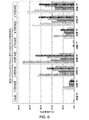
各試験試料は、約18cm2の表面積を有しており、試験法は、Suntestチャンバ(Atlas Material Testing Solutionsから入手可能)を使用して実施された。最初の読取りを実施し、後続の読取りは、Suntestチャンバ内でエージングしてから200時間経った後、500時間経った後、800時間経った後、1100時間経った後、1400時間経った後、1700時間経った後ですすぎ前の時点及び1700時間経った後ですすぎ後の時点において、実施された。Suntestチャンバ内でのエージング中、550w/m2において、250nm〜765nmのスペクトルの光に試料を晒した。評価のために、約0.7L/minでNOが流れているNOx分析装置に試料を入れた。読取りは、7.24W/m2において蛍光(400nm〜750nmのスペクトル)を加えながら、6.63W/m2において紫外光(290nm〜400nmのスペクトル)の影響下で実施された。EnviroTech NOx AnalyzerモデルT200を使用した。さらなるNOx分析装置が、Teledyne Technologies Incorporated、Altech Environment USA及びEmerson Process Management等から市販されている。NOx分析装置は、密封された試験チャンバ(例えば、石英管)、試験チャンバを照明するために構成された光源、NOガス供給源、NOガスを試験チャンバに送達するための管、NOxの存在を検出するために構成された分析装置、試験チャンバから分析装置に気体を送達するための管、浄化された空気(NOxを不含)の供給源、浄化された空気を試験チャンバに送達するための管、水蒸気を試験チャンバに送達するための場合による加湿機、バルブ及びポンプからなる。少なくとも、試験チャンバは、「暗所」における読取りを可能にするために、遮光性容器に入っている。各試験においては、NOx濃度の読取りが、光を加えることなく実施された後、やはり、光を加えて、光触媒条件下におけるNOxの低減を評価した。 Each test sample had a surface area of approximately 18 cm 2 , and the test method was performed using the Suntest chamber (available from Atlas Material Testing Solutions). The first read is performed and the subsequent reads are 200 hours, 500 hours, 800 hours, 1100 hours, 1400 hours, after aging in the Suntest chamber. It was performed after 1700 hours and before rinsing and after 1700 hours and after rinsing. During aging in the Suntest chamber, the sample was exposed to light with a spectrum of 250 nm to 765 nm at 550 w / m 2. For evaluation, the sample was placed in a NOx analyzer in which NO was flowing at about 0.7 L / min. The reading was performed under the influence of ultraviolet light ( spectrum of 290 nm to 400 nm) at 6.63 W / m 2 with fluorescence (spectrum of 400 nm to 750 nm) added at 7.24 W / m 2. An EnviroTech NOx Analyzer model T200 was used. Further NOx analyzers are commercially available from Teledyne Technologies Inc., Altech Environment USA, Emerson Process Management and the like. The NOx analyzer contains a sealed test chamber (eg, a quartz tube), a light source configured to illuminate the test chamber, a NO gas source, a tube for delivering NO gas to the test chamber, and the presence of NOx. An analyzer configured for detection, a tube for delivering gas from the test chamber to the analyzer, a source of purified air (NOx-free), and for delivering purified air to the test chamber. It consists of a tube, a humidifier, a valve and a pump for delivering steam to the test chamber. At a minimum, the test chamber is contained in a light-tight container to allow reading in the "dark place". In each test, NOx concentration readings were performed without light and then light was also added to assess the reduction of NOx under photocatalytic conditions.
試験結果のデータは、下記の表2及び表3に提供されている。試験結果は、図2及び図3にグラフにより示されている。さらに、様々な試験試料のL*値、a*値及びb*値が、表4〜表6に提供されている。NOx低減率%は、式1
[(D−L)/D]×100 式1
に従って計算されており、式中、Dは、暗所条件下で測定されたNO値とNO2値との合計であり、Lは、光条件に晒されている間に測定されたNO値とNO2値との合計である。
The test result data are provided in Tables 2 and 3 below. The test results are shown graphically in FIGS. 2 and 3. Further, L * , a * and b * values of various test samples are provided in Tables 4-6. The NOx reduction rate% is given by Equation 1.
[(DL) / D] × 100 Equation 1
In the formula, D is the sum of the NO value and the NO 2 value measured under dark conditions, and L is the NO value measured while exposed to light conditions. It is the sum with the NO 2 value.
試験法により、白色コーティング層を覆う透明なTiO2ゾルの組み合わせは、平均して、改善されたNOxの低減をもたらすことが示された。このような改善は一般に、白色層のみからできたコーティング又は透明なTiO2ゾルのみからできたコーティングとの比較で確認された。 Test methods have shown that the combination of clear TiO 2 sol covering the white coating layer results in, on average, improved NOx reduction. Such improvements were generally seen in comparison to coatings made entirely of the white layer or coatings made only of the clear TIO 2 sol.
[実施例2]
様々な組み合わせの様々なコーティング材料が、NOx濃度を低減できる度合いを評価した。評価において使用されたコーティング材料は、表7に示されている。
[ Example 2 ]
The degree to which various coating materials in various combinations can reduce the NOx concentration was evaluated. The coating materials used in the evaluation are shown in Table 7.
コーティング材料5、コーティング材料6及びコーティング材料7中に使用された塗料は、Maltbyらの米国特許出願公開第2014/0322116号に記載の配合物であった。コーティング材料5〜7中に使用されたTIONA(商標)595は、Millennium Inorganic Chemicals Ltd.から入手可能である。コーティング材料8〜11は、ナノTiO2が添加された又は添加されていない、一般のスチレンアクリル酸塗料を使用した。 The paints used in the coating material 5, the coating material 6 and the coating material 7 were the formulations described in US Patent Application Publication No. 2014/0322116 by Maltby et al. TIONA ™ 595 used in the coating materials 5-7 is described in Millennium Inorganic Chemicals Ltd. It is available from. As the coating materials 8 to 11, general styrene-acrylic acid paints to which nano TiO 2 was added or not were used.
試験15及び29は、コンクリート上のコーティング材料5の層であった。 Tests 15 and 29 were layers of coating material 5 on concrete.
試験16及び30は、コンクリート上のコーティング材料6の層であった。 Tests 16 and 30 were layers of coating material 6 on concrete.
試験17及び31は、コンクリート上のコーティング材料7の層であった。 Tests 17 and 31 were layers of coating material 7 on concrete.
試験18及び32は、コンクリート上のコーティング材料8の層であった。 Tests 18 and 32 were layers of coating material 8 on concrete.
試験19及び33は、コンクリート上のコーティング材料9の層であった。 Tests 19 and 33 were layers of coating material 9 on concrete.
試験20及び34は、コンクリート上のコーティング材料10の層であった。 Tests 20 and 34 were layers of coating material 10 on concrete.
試験21及び35は、コンクリート上のコーティング材料11の層であった。 Tests 21 and 35 were layers of coating material 11 on concrete.
試験22及び36は、コーティング材料12の層によって被覆されたコンクリート上のコーティング材料5の層であった。 Tests 22 and 36 were layers of coating material 5 on concrete coated with a layer of coating material 12.
試験23及び37は、コーティング材料12の層によって被覆されたコンクリート上のコーティング材料6の層であった。 Tests 23 and 37 were layers of coating material 6 on concrete coated with a layer of coating material 12.
試験24及び38は、コーティング材料12の層によって被覆されたコンクリート上のコーティング材料7の層であった。 Tests 24 and 38 were layers of coating material 7 on concrete coated with a layer of coating material 12.
試験25及び39は、コーティング材料12の層によって被覆されたコンクリート上のコーティング材料8の層であった。 Tests 25 and 39 were layers of coating material 8 on concrete coated with a layer of coating material 12.
試験26及び40は、コーティング材料12の層によって被覆されたコンクリート上のコーティング材料9の層であった。 Tests 26 and 40 were layers of coating material 9 on concrete coated with a layer of coating material 12.
試験27及び41は、コーティング材料12の層によって被覆されたコンクリート上のコーティング材料10の層であった。 Tests 27 and 41 were layers of coating material 10 on concrete coated with a layer of coating material 12.
試験28及び42は、コーティング材料12の層によって被覆されたコンクリート上のコーティング材料11の層であった。 Tests 28 and 42 were layers of coating material 11 on concrete coated with a layer of coating material 12.
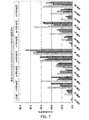
各試験試料は、約18cm2の表面積を有しており、試験法は、実施例1の場合と同様のSuntest Chamber内で実施された。最初の読取りを実施し、後続の読取りは、Suntestチャンバ内でエージングしてから100時間経った後、400時間経った後、900時間経った後ですすぎ前の時点、900時間経った後ですすぎ後の時点及び1200時間経った後において、実施された。Suntestチャンバ内でのエージング中、550w/m2において、250nm〜765nmのスペクトルの光に試料を晒した。評価のために、約0.6L/minでNOが流れているNOx分析装置に試料を入れた。読取りは、7.24W/m2の蛍光(400nm〜750nmのスペクトル)を加えながら、7.19W/m2の紫外光(290nm〜400nmのスペクトル)の影響下で実施された。各試験においては、NOx濃度の読取りが、光を加えることなく実施された後、やはり、光を加えて、光触媒条件下におけるNOxの低減を評価した。 Each test sample had a surface area of about 18 cm 2 , and the test method was performed in the same Suntest Chamber as in Example 1. The first read is performed and the subsequent reads are rinsed 100 hours after aging in the Suntest chamber, 400 hours later, 900 hours later, before rinsing, and 900 hours later. It was performed at a later time and after 1200 hours. During aging in the Suntest chamber, the sample was exposed to light with a spectrum of 250 nm to 765 nm at 550 w / m 2. For evaluation, the sample was placed in a NOx analyzer in which NO was flowing at about 0.6 L / min. The reading was performed under the influence of 7.19 W / m 2 ultraviolet light (290 nm to 400 nm spectrum) with the addition of 7.24 W / m 2 fluorescence (400 nm to 750 nm spectrum). In each test, NOx concentration readings were performed without light and then light was also added to assess the reduction of NOx under photocatalytic conditions.
試験結果のデータは、下記の表8及び表9に提供されている。試験結果は、図4及び図5にグラフにより示されている。さらに、様々な試験試料のL*値、a*値及びb*値が、表10〜表12に提供されている。NOx低減率%を式1に従って計算した。試験法により、白色コーティング層を覆う透明なTiO2ゾルの組み合わせは、平均して、改善されたNOxの低減をもたらすことが示された。このような改善は一般に、白色層のみからできたコーティングとの比較で確認された。 The test result data are provided in Tables 8 and 9 below. The test results are shown graphically in FIGS. 4 and 5. Further, L * , a * and b * values of various test samples are provided in Tables 10-12. The NOx reduction rate% was calculated according to Equation 1. Test methods have shown that the combination of clear TiO 2 sol covering the white coating layer results in, on average, improved NOx reduction. Such improvements were generally seen in comparison to coatings made entirely of the white layer.
[実施例3]
様々な組み合わせの様々なコーティング材料が、NOx濃度を低減できる度合いを評価した。評価において使用されたコーティング材料は、表13に示されている。
[ Example 3 ]
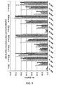
The degree to which various coating materials in various combinations can reduce the NOx concentration was evaluated. The coating materials used in the evaluation are shown in Table 13.
コーティング材料13及び14中に使用された塗料は、一般のスチレンアクリル酸塗料であった。コーティング材料15〜17中に使用された塗料は、Maltbyらの米国特許出願公開第2014/0322116号に記載の配合物であった。コーティング材料13及び15において、ナノTiO2は、ナノTiO2粒子に担持された状態のシリカコーティングを備えていた。コーティング材料14、16及び17において、ナノTiO2粒子を、スラリー形態の塗料に添加した。 The paint used in the coating materials 13 and 14 was a general styrene acrylic acid paint. The paint used in the coating materials 15-17 was the formulation described in US Patent Application Publication No. 2014/0322116 by Maltby et al. In the coating materials 13 and 15, the nano TiO 2 provided a silica coating in a state of being supported on the nano TiO 2 particles. In the coating materials 14, 16 and 17, nanoTiO 2 particles were added to the paint in slurry form.
試験43及び66は、コンクリート上のコーティング材料13の層であった。 Tests 43 and 66 were layers of coating material 13 on concrete.
試験44及び67は、コーティング材料18の層によって被覆されたコンクリート上のコーティング材料13の層であった。 Tests 44 and 67 were layers of coating material 13 on concrete coated with a layer of coating material 18.
試験45及び68は、コーティング材料19の層によって被覆されたコンクリート上のコーティング材料13の層であった。 Tests 45 and 68 were layers of coating material 13 on concrete coated with a layer of coating material 19.
試験46及び69は、コーティング材料20の層によって被覆されたコンクリート上のコーティング材料13の層であった。 Tests 46 and 69 were layers of coating material 13 on concrete coated with a layer of coating material 20.
試験47及び70は、コンクリート上のコーティング材料14の層であった。 Tests 47 and 70 were layers of coating material 14 on concrete.
試験48及び71は、コーティング材料18の層によって被覆されたコンクリート上のコーティング材料14の層であった。 Tests 48 and 71 were layers of coating material 14 on concrete coated with a layer of coating material 18.
試験49及び72は、コーティング材料19の層によって被覆されたコンクリート上のコーティング材料14の層であった。 Tests 49 and 72 were layers of coating material 14 on concrete coated with a layer of coating material 19.
試験50及び73は、コーティング材料20の層によって被覆されたコンクリート上のコーティング材料14の層であった。 Tests 50 and 73 were layers of coating material 14 on concrete coated with a layer of coating material 20.
試験51及び74は、コンクリート上のコーティング材料15の層であった。 Tests 51 and 74 were layers of coating material 15 on concrete.
試験52及び75は、コーティング材料18の層によって被覆されたコンクリート上のコーティング材料15の層であった。 Tests 52 and 75 were layers of coating material 15 on concrete coated with a layer of coating material 18.
試験53及び76は、コーティング材料19の層によって被覆されたコンクリート上のコーティング材料15の層であった。 Tests 53 and 76 were layers of coating material 15 on concrete coated with a layer of coating material 19.
試験54及び77は、コーティング材料20の層によって被覆されたコンクリート上のコーティング材料15の層であった。 Tests 54 and 77 were layers of coating material 15 on concrete coated with a layer of coating material 20.
試験55及び78は、コンクリート上のコーティング材料16の層であった。 Tests 55 and 78 were layers of coating material 16 on concrete.
試験56及び79は、コーティング材料18の層によって被覆されたコンクリート上のコーティング材料16の層であった。 Tests 56 and 79 were layers of coating material 16 on concrete coated with a layer of coating material 18.
試験57及び80は、コーティング材料19の層によって被覆されたコンクリート上のコーティング材料16の層であった。 Tests 57 and 80 were layers of coating material 16 on concrete coated with a layer of coating material 19.
試験58及び81は、コーティング材料20の層によって被覆されたコンクリート上のコーティング材料16の層であった。 Tests 58 and 81 were layers of coating material 16 on concrete coated with a layer of coating material 20.
試験59及び82は、コンクリート上のコーティング材料17の層であった。 Tests 59 and 82 were layers of coating material 17 on concrete.
試験60及び83は、コーティング材料18の層によって被覆されたコンクリート上のコーティング材料17の層であった。 Tests 60 and 83 were layers of coating material 17 on concrete coated with a layer of coating material 18.
試験64及び84は、コーティング材料19の層によって被覆されたコンクリート上のコーティング材料17の層であった。 Tests 64 and 84 were layers of coating material 17 on concrete coated with a layer of coating material 19.
試験62及び85は、コーティング材料20の層によって被覆されたコンクリート上のコーティング材料17の層であった。 Tests 62 and 85 were layers of coating material 17 on concrete coated with a layer of coating material 20.
試験63及び86は、コンクリート上のコーティング材料18のみからできたコーティング層であった。 Tests 63 and 86 were coating layers made entirely of the coating material 18 on concrete.
試験64及び87は、コンクリート上のコーティング材料19のみからできたコーティング層であった。 Tests 64 and 87 were coating layers made entirely of coating material 19 on concrete.
試験65及び88は、コンクリート上のコーティング材料20のみからできたコーティング層であった。 Tests 65 and 88 were coating layers made entirely of the coating material 20 on concrete.
各試験試料は、約18cm2の表面積を有しており、試験法は、実施例1の場合と同様のSuntest Chamber内で実施された。最初の読取りを実施し、後続の読取りは、Suntestチャンバ内でエージングしてから100時間経った後、250時間経った後、400時間経った後、700時間経った後、1000時間経った後及び1300時間経った後に実施された。Suntestチャンバ内でのエージング中、550w/m2において、250nm〜765nmのスペクトルの光に試料を晒した。評価のために、約0.6L/minでNOが流れている50%の相対湿度のNOx分析装置に試料を入れた。読取りは、7.22W/m2の蛍光(400nm〜750nmのスペクトル)を加えながら、6.63W/m2の紫外光(290nm〜400nmのスペクトル)の影響下で実施された。各試験においては、NOx濃度の読取りが、光を加えることなく実施された後、やはり、光を加えて、光触媒条件下におけるNOxの低減を評価した。 Each test sample had a surface area of about 18 cm 2 , and the test method was performed in the same Suntest Chamber as in Example 1. The first read is performed and subsequent reads are 100 hours, 250 hours, 400 hours, 700 hours, 1000 hours, and after aging in the Suntest chamber. It was carried out after 1300 hours. During aging in the Suntest chamber, the sample was exposed to light with a spectrum of 250 nm to 765 nm at 550 w / m 2. For evaluation, the sample was placed in a NOx analyzer with a relative humidity of 50%, where NO was flowing at about 0.6 L / min. The reading was performed under the influence of 6.63 W / m 2 ultraviolet light (290 nm to 400 nm spectrum) with the addition of 7.22 W / m 2 fluorescence (400 nm to 750 nm spectrum). In each test, NOx concentration readings were performed without light and then light was also added to assess the reduction of NOx under photocatalytic conditions.
試験結果のデータは、下記の表14及び表15に提供されている。試験結果は、図6〜図9にグラフにより示されている。NOx低減率%を式1に従って計算した。試験試料の色の外観も、紫外光条件下の試験法の最中に評価した。試料の目視評価が、表16に提供されている。さらに、様々な試験試料のL*値、a*値及びb*値が、表17〜表19に提供されている。試験法により、白色コーティング層を覆う透明なTiO2ゾルの組み合わせは、平均して、改善されたNOxの低減をもたらすことが示された。このような改善は一般に、白色層のみからできたコーティング又は透明なTiO2ゾルのみからできたコーティングとの比較で確認された。 The test result data are provided in Tables 14 and 15 below. The test results are shown graphically in FIGS. 6-9. The NOx reduction rate% was calculated according to Equation 1. The color appearance of the test sample was also evaluated during the test method under UV light conditions. A visual assessment of the sample is provided in Table 16. In addition, L * , a * and b * values for various test samples are provided in Tables 17-19. Test methods have shown that the combination of clear TiO 2 sol covering the white coating layer results in, on average, improved NOx reduction. Such improvements were generally seen in comparison to coatings made entirely of the white layer or coatings made only of the clear TIO 2 sol.
本開示は以下の実施形態を含む。
[1]
基体、
入射光の少なくとも約60%を反射するようになされた前記基体上の第1のコーティング層、及び
実質的に透明又は半透明であり、光触媒作用のある二酸化チタンを含む、前記第1のコーティング層を覆った第2のコーティング層を備える、積層構造体。
[2]
基体が、セメント質、木材、金属、メーソンリー、プラスチック、紙又は石膏である、[1]に記載の積層構造体。
[3]
第1のコーティング層が、塗料である、[1]に記載の積層構造体。
[4]
第1のコーティング層が、白系の可視色を有する、[1]に記載の積層構造体。
[5]
第1のコーティングの色が、約90超のL * 値、約−5〜約+5のa * 値及び約−2及び約+10のb * 値によって規定されている、[1]に記載の積層構造体。
[6]
紫外光への100時間の曝露後、第1のコーティングの色が、95.0〜97.0のL * 値、−1.50〜−0.50のa * 値及び1.0〜4.0のb * 値によって規定されるという条件、及び
紫外光への1300時間の曝露後、第1のコーティングの色が、95.0〜97.5のL * 値、−1.00〜−0.45のa * 値及び1.0〜2.5のb * 値によって規定されるという条件
のうちの1つが、満たされている、[5]に記載の積層構造体。
[7]
第2のコーティング層が、約0.1重量%〜約30重量%の二酸化チタンを含む、[1]に記載の積層構造体。
[8]
光触媒作用のある二酸化チタンが、100nm未満の平均サイズを有する粒子の形態である、[1]に記載の積層構造体。
[9]
第1のコーティング層が、白色顔料を含む、[1]に記載の積層構造体。
[10]
第2のコーティング層が、NOxの酸化を触媒するようになされている、[1]に記載の積層構造体。
[11]
第1のコーティング層を覆う第2のコーティング層の組み合わせが、第2のコーティング層それ自体に比べて増加した速度にてNOxの酸化を触媒するのに有効である、[10]に記載の積層構造体。
[12]
増加した速度が、相乗効果に起因する、[11]に記載の積層構造体。
[13]
第1のコーティング層を覆う第2のコーティング層の組み合わせによるNOxの酸化が、第2の層それ自体によるNO x の酸化より少なくとも約10%大きい、[11]に記載の積層構造体。
[14]
基体構造の付近にあるNO x を除去する方法であって、
前記基体構造の表面の少なくとも一部に、入射光の少なくとも約60%を反射するようになされた第1のコーティング材料の層を備え付けること及び
実質的に透明又は半透明であり、前記基体構造の付近にあるNOxの少なくとも一部の酸化を触媒するのに有効な量の光触媒作用のある二酸化チタンを含む、第2のコーティング材料の層を、前記第1のコーティング材料の前記層を覆うように設けること
を含む、方法。
[15]
基体構造が、立体駐車場又は道路構造である、[14]に記載の方法。
[16]
光触媒作用のあるTiO 2 材料によってNOxの低減を改善する方法であって、
前記光触媒作用のあるTiO 2 材料を含む透明又は半透明な層を、入射光の少なくとも約60%を反射するようなされたある材料からできたさらなる層と、前記透明又は半透明な層が前記さらなる層の上に覆うように組み合わせることを含み、
前記さらなる層を覆う前記透明又は半透明な層の組み合わせが、前記透明又は半透明な層それ自体に比べて増加した速度にてNOxの酸化を触媒するのに有効である、
方法。
[17]
増加した速度が、相乗効果に起因する、[16]に記載の方法。
[18]
前記さらなる層を覆う透明又は半透明な層の組み合わせによるNOxの酸化が、透明又は半透明な層それ自体によるNOxの酸化より少なくとも約10%大きい、[16]に記載の方法。
[19]
第1のコーティング層又はある材料からできたさらなる層が、白系の可視色を有する、[14]又は[16]に記載の方法。
[20]
第1のコーティング層又はある材料からできたさらなる層が、約90超のL * 値、約−5〜約+5のa * 値及び約−2〜約+10のb * 値によって規定された色を有する、[14]又は[16]に記載の方法。
[21]
紫外光への100時間の曝露後、第1のコーティング層又はある材料からできたさらなる層の色が、95.0〜97.0のL * 値、−1.50〜−0.50のa * 値及び1.0〜4.0のb * 値によって規定されるという条件、及び
紫外光への1300時間の曝露後、第1のコーティング層又はある材料からできたさらなる層の色が、95.0〜97.5のL * 値、−1.00〜−0.45のa * 値及び1.0〜2.5のb * 値によって規定されるという条件
のうちの1つが、満たされている、[20]に記載の方法。
数多くの本発明の修正形態及び他の実施形態が、上記の記述において提供された教示の利益を受ける、本発明が属する分野の当業者によって想到される。したがって、本発明は、開示された特定の実施形態に限定すべきでなく、修正形態及び他の実施形態は、添付の特許請求の範囲に含まれるように意図されていることを理解すべきである。本明細書において、特定の用語が採用されているが、これらの用語は、一般的な説明用の意味においてのみ使用されており、限定を目的として使用されているわけではない。
The disclosure includes the following embodiments:
[1]
Hypokeimenon,
A first coating layer on the substrate that reflects at least about 60% of the incident light, and
A laminated structure comprising a second coating layer that covers the first coating layer, which is substantially transparent or translucent and contains titanium dioxide which is photocatalytic.
[2]
The laminated structure according to [1], wherein the substrate is cementum, wood, metal, masonry, plastic, paper or gypsum.
[3]
The laminated structure according to [1], wherein the first coating layer is a paint.
[4]
The laminated structure according to [1], wherein the first coating layer has a white-based visible color.
[5]
The color of the first coating comprises about 90 greater L * value is defined by about -5 to about +5 a * value and about -2 and about +10 b * values, laminate according to [1] Structure.
[6]
After 100 hours of exposure to ultraviolet light, the color of the first coating was 95.0-97.0 L * value, -1.50-0.50 a * value and 1.0-4. The condition that it is defined by the b * value of 0, and
After 1300 hours of exposure to ultraviolet light, the colors of the first coating were L * values from 95.0 to 97.5, a * values from -1.00 to -0.45 and 1.0 to 2. Condition specified by the b * value of 5
The laminated structure according to [5], wherein one of them is filled.
[7]
The laminated structure according to [1], wherein the second coating layer contains about 0.1% by weight to about 30% by weight of titanium dioxide.
[8]
The laminated structure according to [1], wherein the photocatalytic titanium dioxide is in the form of particles having an average size of less than 100 nm.
[9]
The laminated structure according to [1], wherein the first coating layer contains a white pigment.
[10]
The laminated structure according to [1], wherein the second coating layer is designed to catalyze the oxidation of NOx.
[11]
The laminate according to [10], wherein the combination of the second coating layer covering the first coating layer is effective in catalyzing the oxidation of NOx at an increased rate as compared with the second coating layer itself. Structure.
[12]
The laminated structure according to [11], wherein the increased speed is due to a synergistic effect.
[13]
Oxidation of NOx with a combination of second coating layer covering the first coating layer is at least about 10% greater than the oxidation of the NO x by the second layer itself, the laminated structure according to [11].
[14]
It is a method of removing NO x in the vicinity of the substrate structure.
At least a portion of the surface of the substrate structure is provided with a layer of first coating material adapted to reflect at least about 60% of the incident light.
A layer of second coating material that is substantially transparent or translucent and contains a photocatalytic titanium dioxide in an amount effective to catalyze the oxidation of at least a portion of NOx in the vicinity of said substrate structure. , Provided so as to cover the layer of the first coating material.
Including methods.
[15]
The method according to [14], wherein the substrate structure is a multi-storey car park or a road structure.
[16]
A method of improving the reduction of NOx with a photocatalytic TiO 2 material.
A transparent or translucent layer containing the photocatalytic TiO 2 material, an additional layer made of a material such as to reflect at least about 60% of the incident light, and the transparent or translucent layer said further. Including combining to cover over layers
The combination of the transparent or translucent layers covering the additional layer is effective in catalyzing the oxidation of NOx at an increased rate as compared to the transparent or translucent layer itself.
Method.
[17]
The method according to [16], wherein the increased speed is due to a synergistic effect.
[18]
The method according to [16], wherein the oxidation of NOx by the combination of transparent or translucent layers covering the additional layer is at least about 10% greater than the oxidation of NOx by the transparent or translucent layer itself.
[19]
The method according to [14] or [16], wherein the first coating layer or an additional layer made of a certain material has a whiteish visible color.
[20]
Additional layers made from the first coating layer or material, about 90 greater L * value, a color defined by about -5 to about +5 a * value and about -2 to about +10 b * value The method according to [14] or [16].
[21]
After 100 hours of exposure to UV light, the color of the first coating layer or an additional layer made of some material has an L * value of 95.0-97.0, a of -1.50 to -0.50 a. * values and the condition that is defined by the b * value of 1.0 to 4.0, and
After 1300 hours of exposure to UV light, the color of the first coating layer or an additional layer made of some material has an L * value of 95.0-97.5, -1.00-0.45 a. condition that is defined by the * value and 1.0 to 2.5 of the b * value
The method according to [20], wherein one of them is satisfied.
Numerous modifications and other embodiments of the invention will be conceived by those skilled in the art to which the invention belongs, benefiting from the teachings provided in the above description. Therefore, it should be understood that the present invention should not be limited to the specified embodiments disclosed, and that the modifications and other embodiments are intended to be included in the appended claims. be. Although specific terms have been adopted herein, they are used only for general descriptive purposes and are not used for limitation purposes.
Claims (11)
入射光の少なくとも60%を反射するようになされた前記基体上の第1のコーティング層、及び
透明又は半透明であり、光触媒作用のある二酸化チタンを含む、前記第1のコーティング層を覆った第2のコーティング層
を備え、
前記第2のコーティング層が、0.1重量%〜30重量%の二酸化チタンを含む、
NOx低減用積層構造体。
Hypokeimenon,
A first coating layer on the substrate that reflects at least 60% of the incident light, and
A transparency or translucent, containing titanium dioxide with a photocatalytic effect, a second coating layer covering the first coating layer,
The second coating layer contains from 0.1% to 30% by weight titanium dioxide.
Laminated structure for NOx reduction.
紫外光への1300時間の曝露後、第1のコーティングの色が、95.0〜97.5のL*値、−1.00〜−0.45のa*値及び1.0〜2.5のb*値によって規定されるという条件
のうちの1つが、満たされている、請求項5に記載の積層構造体。 After 100 hours of exposure to UV light, the colors of the first coating were 95.0-97.0 L * values, -1.50-0.50 a * values and 1.0-4. The condition that it is defined by a b * value of 0, and after 1300 hours of exposure to UV light, the color of the first coating is an L * value of 95.0-97.5, -1.00-0. The laminated structure according to claim 5, wherein one of the conditions specified by the a * value of .45 and the b * value of 1.0 to 2.5 is satisfied.
First combination due to the oxidation of NOx in the second coating layer covering the coating layer, 1 0 percent and less than the oxidation of NOx by the second layer itself large, multilayer structure according to claim 9 or 10 ..
Priority Applications (1)
| Application Number | Priority Date | Filing Date | Title |
|---|---|---|---|
| JP2021091439A JP7245869B2 (en) | 2015-10-21 | 2021-05-31 | Coatings that reduce NOx and methods for reducing NOx with such coatings |
Applications Claiming Priority (3)
| Application Number | Priority Date | Filing Date | Title |
|---|---|---|---|
| US201562244217P | 2015-10-21 | 2015-10-21 | |
| US62/244,217 | 2015-10-21 | ||
| PCT/US2016/058175 WO2017070507A1 (en) | 2015-10-21 | 2016-10-21 | Nox reducing coatings and methods for reducing nox therewith |
Related Child Applications (1)
| Application Number | Title | Priority Date | Filing Date |
|---|---|---|---|
| JP2021091439A Division JP7245869B2 (en) | 2015-10-21 | 2021-05-31 | Coatings that reduce NOx and methods for reducing NOx with such coatings |
Publications (2)
| Publication Number | Publication Date |
|---|---|
| JP2018537310A JP2018537310A (en) | 2018-12-20 |
| JP6914927B2 true JP6914927B2 (en) | 2021-08-04 |
Family
ID=57219057
Family Applications (2)
| Application Number | Title | Priority Date | Filing Date |
|---|---|---|---|
| JP2018520472A Active JP6914927B2 (en) | 2015-10-21 | 2016-10-21 | Coatings that reduce NOx and methods for reducing NOx by the coating |
| JP2021091439A Active JP7245869B2 (en) | 2015-10-21 | 2021-05-31 | Coatings that reduce NOx and methods for reducing NOx with such coatings |
Family Applications After (1)
| Application Number | Title | Priority Date | Filing Date |
|---|---|---|---|
| JP2021091439A Active JP7245869B2 (en) | 2015-10-21 | 2021-05-31 | Coatings that reduce NOx and methods for reducing NOx with such coatings |
Country Status (13)
| Country | Link |
|---|---|
| US (1) | US10639614B2 (en) |
| EP (1) | EP3365394B1 (en) |
| JP (2) | JP6914927B2 (en) |
| KR (1) | KR102419051B1 (en) |
| CN (1) | CN108603049B (en) |
| BR (1) | BR112018007865B1 (en) |
| DK (1) | DK3365394T3 (en) |
| ES (1) | ES2807874T3 (en) |
| MX (1) | MX2018004942A (en) |
| PH (1) | PH12018500853A1 (en) |
| PL (1) | PL3365394T3 (en) |
| SI (1) | SI3365394T1 (en) |
| WO (1) | WO2017070507A1 (en) |
Families Citing this family (1)
| Publication number | Priority date | Publication date | Assignee | Title |
|---|---|---|---|---|
| CN111848084A (en) * | 2020-07-21 | 2020-10-30 | 兰州理工大学 | High-strength gypsum-based wall body for weakening electromagnetic radiation and carrying out photocatalysis on harmful gas |
Family Cites Families (35)
| Publication number | Priority date | Publication date | Assignee | Title |
|---|---|---|---|---|
| DE3777931D1 (en) | 1986-09-22 | 1992-05-07 | Ishihara Sangyo Kaisha | TITANIUM DIOXYDSOL AND METHOD FOR THE PRODUCTION THEREOF. |
| JP2988376B2 (en) * | 1996-01-24 | 1999-12-13 | 三菱マテリアル株式会社 | NOx purification block for paving |
| JPH09293405A (en) * | 1996-04-30 | 1997-11-11 | Toshiba Lighting & Technol Corp | Reflector, incandescent lamp and luminaire |
| JP3080162B2 (en) | 1998-01-27 | 2000-08-21 | 日本パーカライジング株式会社 | Titanium oxide sol and method for producing the same |
| JPH11285643A (en) * | 1998-04-03 | 1999-10-19 | Matsushita Seiko Co Ltd | Photocatalytic deodorization body and photocatalytic deodorization unit |
| JP2000189809A (en) * | 1999-01-01 | 2000-07-11 | Toto Ltd | Member having photocatalytic function |
| JP2000285715A (en) * | 1999-03-31 | 2000-10-13 | Toshiba Lighting & Technology Corp | Reflector, lamp device and a case device |
| IT1312119B1 (en) | 1999-06-25 | 2002-04-04 | Italcementi Spa | USE OF TITANIUM COLLOIDAL DIOXIDE PHOTOCATALYTIC PREPARATIONS TO PRESERVE THE ORIGINAL APPEARANCE OF CAMENTIC, STONE OR |
| JP2001297614A (en) | 2000-04-15 | 2001-10-26 | Taiyo Seisakusho:Kk | Titanium oxide functional light reflector |
| JP4588164B2 (en) | 2000-05-10 | 2010-11-24 | 日新製鋼株式会社 | Pre-coated metal plate and manufacturing method thereof |
| WO2002004376A1 (en) * | 2000-07-12 | 2002-01-17 | Nippon Sheet Glass Co., Ltd. | Photocatalytic member |
| US7288232B2 (en) * | 2001-09-24 | 2007-10-30 | L2B Environmental Systems, Inc. | Self-cleaning UV reflective coating |
| US6672336B2 (en) | 2001-11-28 | 2004-01-06 | Rheodyne, Lp | Dual random access, three-way rotary valve apparatus |
| US20050129589A1 (en) * | 2003-12-16 | 2005-06-16 | Di Wei | Multi-layered photocatalyst/thermocatalyst for improving indoor air quality |
| WO2005083013A1 (en) | 2004-01-30 | 2005-09-09 | Millennium Chemicals | Coating composition having surface depolluting properties |
| CN100519485C (en) | 2004-01-30 | 2009-07-29 | 美礼联化工英国控股有限公司 | Composition for NOx removing translucent coating |
| KR100727579B1 (en) | 2005-12-20 | 2007-06-14 | 주식회사 엘지화학 | Titania sol, preparing method thereof and composition for coating comprising thereof |
| JP2008238767A (en) * | 2007-03-29 | 2008-10-09 | Sekisui Jushi Co Ltd | Low-staining outdoor structure |
| US9358502B2 (en) | 2007-08-31 | 2016-06-07 | Cristal Usa Inc. | Photocatalytic coating |
| US7763565B2 (en) * | 2007-08-31 | 2010-07-27 | Millennium Inorganic Chemicals, Inc. | Transparent, stable titanium dioxide sols |
| FR2920762B1 (en) * | 2007-09-10 | 2009-10-23 | Saint Gobain | MATERIAL WITH PHOTOCATALYTIC PROPERTIES |
| US7776954B2 (en) | 2008-01-30 | 2010-08-17 | Millenium Inorganic Chemicals, Inc. | Photocatalytic coating compositions |
| JP2009247546A (en) | 2008-04-04 | 2009-10-29 | Sharp Corp | Air cleaning filter and air cleaner |
| WO2009141877A1 (en) | 2008-05-20 | 2009-11-26 | イビデン株式会社 | Honeycomb structure |
| TWI440505B (en) * | 2008-05-27 | 2014-06-11 | Toto Ltd | Photocatalyst coating |
| US20110159109A1 (en) | 2008-09-02 | 2011-06-30 | Drexel University | Titania dispersion and method for making |
| JP5305231B2 (en) | 2009-01-28 | 2013-10-02 | Toto株式会社 | Photocatalyst paint |
| US8110297B2 (en) * | 2009-02-18 | 2012-02-07 | Guardian Industries Corp. | Coated article supporting photocatalytic layer and UV-reflecting underlayer, and/or method of making the same |
| FR2948037B1 (en) * | 2009-07-17 | 2012-12-28 | Saint Gobain | PHOTOCATALYTIC MATERIAL |
| SG187646A1 (en) | 2010-07-29 | 2013-03-28 | Toto Ltd | Photocatalyst coated body and photocatalyst coating liquid |
| JP5951645B2 (en) * | 2011-01-31 | 2016-07-13 | トーレ・フィルムズ・ユアロップ | MULTILAYER WHITE POLYESTER FILM, METHOD FOR PRODUCING FILM, AND USE OF FILM AS PART OF SOLAR CELL BACK SHEET |
| PT2780108T (en) * | 2011-11-16 | 2021-03-03 | Tronox Llc | Neutral, stable and transparent photocatalytic titanium dioxide sols |
| EP3017080A2 (en) * | 2013-07-05 | 2016-05-11 | Nitto Denko Corporation | Transparent photocatalyst coating and methods of manufacturing the same |
| JP5936735B1 (en) * | 2015-03-13 | 2016-06-22 | 株式会社バイオミミック | Method for producing interior composite film containing anatase type titanium oxide |
| CN206155096U (en) * | 2016-06-30 | 2017-05-10 | 科世达(上海)管理有限公司 | Air purification door window and vehicle |
-
2016
- 2016-10-21 BR BR112018007865-4A patent/BR112018007865B1/en active IP Right Grant
- 2016-10-21 DK DK16788920.3T patent/DK3365394T3/en active
- 2016-10-21 WO PCT/US2016/058175 patent/WO2017070507A1/en active Application Filing
- 2016-10-21 SI SI201630880T patent/SI3365394T1/en unknown
- 2016-10-21 EP EP16788920.3A patent/EP3365394B1/en active Active
- 2016-10-21 ES ES16788920T patent/ES2807874T3/en active Active
- 2016-10-21 MX MX2018004942A patent/MX2018004942A/en unknown
- 2016-10-21 PL PL16788920T patent/PL3365394T3/en unknown
- 2016-10-21 CN CN201680075388.9A patent/CN108603049B/en active Active
- 2016-10-21 KR KR1020187013832A patent/KR102419051B1/en active IP Right Grant
- 2016-10-21 JP JP2018520472A patent/JP6914927B2/en active Active
- 2016-10-21 US US15/769,396 patent/US10639614B2/en active Active
-
2018
- 2018-04-20 PH PH12018500853A patent/PH12018500853A1/en unknown
-
2021
- 2021-05-31 JP JP2021091439A patent/JP7245869B2/en active Active
Also Published As
| Publication number | Publication date |
|---|---|
| JP2021154281A (en) | 2021-10-07 |
| WO2017070507A1 (en) | 2017-04-27 |
| MX2018004942A (en) | 2018-07-06 |
| PL3365394T3 (en) | 2020-11-30 |
| JP7245869B2 (en) | 2023-03-24 |
| US10639614B2 (en) | 2020-05-05 |
| KR102419051B1 (en) | 2022-07-07 |
| BR112018007865B1 (en) | 2022-08-23 |
| ES2807874T3 (en) | 2021-02-24 |
| CN108603049B (en) | 2021-06-01 |
| US20180304234A1 (en) | 2018-10-25 |
| PH12018500853B1 (en) | 2018-11-05 |
| SI3365394T1 (en) | 2020-10-30 |
| EP3365394B1 (en) | 2020-06-03 |
| JP2018537310A (en) | 2018-12-20 |
| BR112018007865A2 (en) | 2018-10-30 |
| EP3365394A1 (en) | 2018-08-29 |
| PH12018500853A1 (en) | 2018-11-05 |
| KR20180073609A (en) | 2018-07-02 |
| CN108603049A (en) | 2018-09-28 |
| DK3365394T3 (en) | 2020-08-03 |
Similar Documents
| Publication | Publication Date | Title |
|---|---|---|
| Calia et al. | Durability assessment of nanostructured TiO2 coatings applied on limestones to enhance building surface with self-cleaning ability | |
| Petrovič et al. | Determination of the photocatalytic efficiency of TiO2 coatings on ceramic tiles by monitoring the photodegradation of organic dyes | |
| JP4092714B1 (en) | Photocatalyst-coated body and photocatalyst coating liquid therefor | |
| Colangiuli et al. | Field study in an urban environment of simultaneous self-cleaning and hydrophobic nanosized TiO2-based coatings on stone for the protection of building surface | |
| Gherardi et al. | Efficient self-cleaning treatments for built heritage based on highly photo-active and well-dispersible TiO2 nanocrystals | |
| CN104759297B (en) | Object with photo-catalyst coating and photocatalyst coating liquid | |
| JP2009072753A (en) | Photocatalytic composition for anti-reflection and glass substrate using the composition | |
| TW201127490A (en) | Photocatalyst-coated object and photocatalyst coating liquid therefor | |
| Galenda et al. | Evaluation of self-cleaning photocatalytic paints: Are they effective under actual indoor lighting systems? | |
| KR20120081984A (en) | Photocatalyst-coated object and photocatalyst coating liquid therefor | |
| Fan et al. | Advanced solar photocatalytic asphalt for removal of vehicular NOx | |
| Lettieri et al. | Nanostructured TiO 2 for stone coating: Assessing compatibility with basic stone’s properties and photocatalytic effectiveness | |
| JP2010007088A (en) | Photocatalyst-coated body and photocatalytic coating liquid therefor | |
| JP2021154281A (en) | Nox reducing coating and method for reducing nox therewith | |
| Giampiccolo et al. | UV/visible sol gel W–TiO2 photocatalytic coatings for interior building surfaces | |
| O'Keeffe et al. | Air purification by heterogeneous photocatalytic oxidation with multi-doped thin film titanium dioxide | |
| Homa et al. | Impact of paint matrix composition and thickness of paint layer on the activity of photocatalytic paints | |
| TWI430841B (en) | With the use of photocatalyst layer of composite materials | |
| JP5305231B2 (en) | Photocatalyst paint | |
| JP2011072935A (en) | Photocatalyst-coated object and photocatalyst coating liquid therefor | |
| JP2009255571A (en) | Photocatalyst-applied object, and photocatalyst coating liquid therefor | |
| Pichat | New and Future Developments in Catalysis: Chapter 7. Self-Cleaning Materials Based on Solar Photocatalysis | |
| JP2011078916A (en) | External structure and coating fluid for external structure | |
| Goffredo et al. | Doctoral School on Engineering Sciences | |
| JP2011006957A (en) | Gate door |
Legal Events
| Date | Code | Title | Description |
|---|---|---|---|
| A711 | Notification of change in applicant |
Free format text: JAPANESE INTERMEDIATE CODE: A711 Effective date: 20190731 |
|
| A621 | Written request for application examination |
Free format text: JAPANESE INTERMEDIATE CODE: A621 Effective date: 20190805 |
|
| A977 | Report on retrieval |
Free format text: JAPANESE INTERMEDIATE CODE: A971007 Effective date: 20200731 |
|
| A131 | Notification of reasons for refusal |
Free format text: JAPANESE INTERMEDIATE CODE: A131 Effective date: 20200825 |
|
| A521 | Request for written amendment filed |
Free format text: JAPANESE INTERMEDIATE CODE: A523 Effective date: 20201118 |
|
| A131 | Notification of reasons for refusal |
Free format text: JAPANESE INTERMEDIATE CODE: A131 Effective date: 20210316 |
|
| A521 | Request for written amendment filed |
Free format text: JAPANESE INTERMEDIATE CODE: A523 Effective date: 20210531 |
|
| TRDD | Decision of grant or rejection written | ||
| A01 | Written decision to grant a patent or to grant a registration (utility model) |
Free format text: JAPANESE INTERMEDIATE CODE: A01 Effective date: 20210706 |
|
| A61 | First payment of annual fees (during grant procedure) |
Free format text: JAPANESE INTERMEDIATE CODE: A61 Effective date: 20210714 |
|
| R150 | Certificate of patent or registration of utility model |
Ref document number: 6914927 Country of ref document: JP Free format text: JAPANESE INTERMEDIATE CODE: R150 |