JP6914735B2 - Image forming device - Google Patents
Image forming device Download PDFInfo
- Publication number
- JP6914735B2 JP6914735B2 JP2017108240A JP2017108240A JP6914735B2 JP 6914735 B2 JP6914735 B2 JP 6914735B2 JP 2017108240 A JP2017108240 A JP 2017108240A JP 2017108240 A JP2017108240 A JP 2017108240A JP 6914735 B2 JP6914735 B2 JP 6914735B2
- Authority
- JP
- Japan
- Prior art keywords
- measurement
- sheet
- image
- color
- length
- Prior art date
- Legal status (The legal status is an assumption and is not a legal conclusion. Google has not performed a legal analysis and makes no representation as to the accuracy of the status listed.)
- Active
Links
Images


Classifications
-
- G—PHYSICS
- G03—PHOTOGRAPHY; CINEMATOGRAPHY; ANALOGOUS TECHNIQUES USING WAVES OTHER THAN OPTICAL WAVES; ELECTROGRAPHY; HOLOGRAPHY
- G03G—ELECTROGRAPHY; ELECTROPHOTOGRAPHY; MAGNETOGRAPHY
- G03G15/00—Apparatus for electrographic processes using a charge pattern
- G03G15/50—Machine control of apparatus for electrographic processes using a charge pattern, e.g. regulating differents parts of the machine, multimode copiers, microprocessor control
- G03G15/5062—Machine control of apparatus for electrographic processes using a charge pattern, e.g. regulating differents parts of the machine, multimode copiers, microprocessor control by measuring the characteristics of an image on the copy material
-
- G—PHYSICS
- G03—PHOTOGRAPHY; CINEMATOGRAPHY; ANALOGOUS TECHNIQUES USING WAVES OTHER THAN OPTICAL WAVES; ELECTROGRAPHY; HOLOGRAPHY
- G03G—ELECTROGRAPHY; ELECTROPHOTOGRAPHY; MAGNETOGRAPHY
- G03G15/00—Apparatus for electrographic processes using a charge pattern
- G03G15/01—Apparatus for electrographic processes using a charge pattern for producing multicoloured copies
-
- G—PHYSICS
- G03—PHOTOGRAPHY; CINEMATOGRAPHY; ANALOGOUS TECHNIQUES USING WAVES OTHER THAN OPTICAL WAVES; ELECTROGRAPHY; HOLOGRAPHY
- G03G—ELECTROGRAPHY; ELECTROPHOTOGRAPHY; MAGNETOGRAPHY
- G03G15/00—Apparatus for electrographic processes using a charge pattern
- G03G15/50—Machine control of apparatus for electrographic processes using a charge pattern, e.g. regulating differents parts of the machine, multimode copiers, microprocessor control
- G03G15/5033—Machine control of apparatus for electrographic processes using a charge pattern, e.g. regulating differents parts of the machine, multimode copiers, microprocessor control by measuring the photoconductor characteristics, e.g. temperature, or the characteristics of an image on the photoconductor
- G03G15/5041—Detecting a toner image, e.g. density, toner coverage, using a test patch
-
- G—PHYSICS
- G03—PHOTOGRAPHY; CINEMATOGRAPHY; ANALOGOUS TECHNIQUES USING WAVES OTHER THAN OPTICAL WAVES; ELECTROGRAPHY; HOLOGRAPHY
- G03G—ELECTROGRAPHY; ELECTROPHOTOGRAPHY; MAGNETOGRAPHY
- G03G2215/00—Apparatus for electrophotographic processes
- G03G2215/00025—Machine control, e.g. regulating different parts of the machine
- G03G2215/00029—Image density detection
- G03G2215/00033—Image density detection on recording member
- G03G2215/00037—Toner image detection
- G03G2215/00042—Optical detection
Description
本発明は、測定手段による測定用画像の測定結果に基づいて色変換条件を生成する生成処理に関する。 The present invention relates to a generation process for generating color conversion conditions based on the measurement results of a measurement image by a measuring means.
近年の画像形成装置は、シートが搬送される搬送路に、シート上に形成された測定用画像を測定する測定手段を備えている。この画像形成装置は、測定手段による測定用画像の測定結果に基づいて画像形成条件を調整することができる。 A recent image forming apparatus includes a measuring means for measuring a measurement image formed on a sheet in a transport path through which the sheet is conveyed. This image forming apparatus can adjust the image forming conditions based on the measurement result of the measurement image by the measuring means.
また、汎用の測色器が接続可能な画像処理装置も知られている。このような画像形成装置は、汎用の測色器によりカラーチャートを測定した結果に基づいて画像形成条件を調整することも可能である。 An image processing device to which a general-purpose colorimeter can be connected is also known. Such an image forming apparatus can also adjust the image forming conditions based on the result of measuring the color chart with a general-purpose colorimeter.
しかしながら、測定手段と測色器とのいずれを用いても画像形成条件を調整可能な画像形成装置においては、測色デバイスの特性の違いによって、カラーチャートを測定した測色値が異なってしまう可能性がある。 However, in an image forming apparatus whose image forming conditions can be adjusted by using either a measuring means or a color measuring device, the color measurement value measured by the color chart may differ due to the difference in the characteristics of the color measuring device. There is sex.
そのため、従来、測色デバイスの特性の違いによって生じてしまう測色値の差異に対して、デバイス間の補正を行うことで特性の違いを軽減する方法が提案されている。例えば、カラーチャートを、基準となる測色デバイスと補正対象となる測色デバイスの両方で測定し、それぞれの測定値の関係から補正係数を求める方法が知られている(特許文献1参照)。特許文献1に記載の方法は、異なる測色デバイスが同じカラーチャート(以降、共通カラーチャートと称す。)を測定する。
Therefore, conventionally, a method of reducing the difference in characteristics by performing correction between devices has been proposed for the difference in color measurement values caused by the difference in characteristics of color measurement devices. For example, there is known a method in which a color chart is measured by both a reference color measuring device and a color measuring device to be corrected, and a correction coefficient is obtained from the relationship between the measured values (see Patent Document 1). In the method described in
ところで、異なる種類の測色デバイスが共通カラーチャートを測定するためには、画像形成装置が各デバイスに適したレイアウトの共通カラーチャートを印刷する必要がある。ここで、搬送路に設けられた測定手段と、画像形成装置に接続可能なセンサとでは、カラーチャートの測定規則が異なる。例えば、測定手段は、搬送路に沿って搬送されるカラーチャートを測定するので、カラーチャート上に形成された測定用画像の位置及び寸法に明確な規則が存在する。つまり、一方の測色デバイスのみでの測色を考慮したカラーチャートでは、他方の測色デバイスで測定することができない可能性がある。 By the way, in order for different types of color measuring devices to measure a common color chart, it is necessary for the image forming apparatus to print a common color chart having a layout suitable for each device. Here, the measurement rules of the color chart are different between the measuring means provided in the transport path and the sensor that can be connected to the image forming apparatus. For example, since the measuring means measures the color chart transported along the transport path, there are clear rules for the position and dimensions of the measurement image formed on the color chart. That is, in a color chart that considers color measurement with only one color measuring device, it may not be possible to measure with the other color measuring device.
そこで、本発明の目的は、異なるキャリブレーションの各々に適したカラーチャートを形成することにある。 Therefore, an object of the present invention is to form a color chart suitable for each of the different calibrations.
上記課題を解決するため、本発明の画像形成装置は、搬送路に沿ってシートを搬送する搬送手段と、画像データを色変換条件に基づいて変換する色変換手段と、前記変換された前記画像データに基づいて、前記シートに画像を形成する画像形成手段と、前記搬送路に設けられ、前記シート上の測定用画像を測定する測定手段と、前記測定手段の測定結果を変換条件に基づいて変換する変換手段と、前記搬送手段を制御して前記シートを搬送させ、前記画像形成手段を制御して前記シートに複数の第1測定用画像を含む第1パターン画像を形成させ、前記測定手段を制御して前記シート上の前記複数の第1測定用画像を測定させ、前記変換手段によって前記複数の第1測定用画像の測定結果を第1測定データに変換させ、前記色変換条件を前記第1測定データに基づいて生成する第1生成手段と、前記搬送手段を制御して前記シートを搬送させ、前記画像形成手段により前記シートに複数の第2測定用画像を含む第2パターン画像を形成させ、前記測定手段を制御して前記シート上の前記複数の第2測定用画像を測定させ、外部センサから出力された前記シート上の前記複数の第2測定用画像の測定結果に対応する第2測定データを取得し、前記測定手段による前記複数の第2測定用画像の測定結果と前記第2測定データとに基づいて前記変換条件を生成する第2生成手段と、を有し、前記複数の第1測定用画像は、前記シートが搬送される搬送方向の長さが第1の長さになるように前記シートに形成される第1測定用画像と、前記搬送方向の長さが前記第1の長さより長い第2の長さとなるように前記シートに形成される第1測定用画像とを有し、前記第1の長さになるように前記シートに形成される前記第1測定用画像の位置と前記第2の長さとなるように前記シートに形成される前記第1測定用画像の位置とは前記搬送方向において異なっており、前記搬送方向の長さが前記第2の長さとなるように前記シートに形成される前記第1測定用画像は、前記複数の第1測定用画像の前記測定結果を取得するために前記測定手段が前記複数の第1測定用画像を測定する際に前記搬送方向において前記複数の第1測定用画像のなかで最も後端に位置しており、前記複数の第2測定用画像の各々は、前記搬送方向の長さが前記第2の長さ以上の第3の長さとなるように、前記搬送方向において前記シートの異なる位置に形成されることを特徴とする。 In order to solve the above problems, the image forming apparatus of the present invention includes a transport means for transporting a sheet along a transport path, a color conversion means for converting image data based on color conversion conditions, and the converted image. Based on the conversion conditions, the image forming means for forming an image on the sheet, the measuring means provided on the transport path for measuring the measurement image on the sheet, and the measurement result of the measuring means based on the data. The conversion means to be converted and the transfer means are controlled to convey the sheet, and the image forming means is controlled to form a first pattern image including a plurality of first measurement images on the sheet, and the measurement means. Is controlled to measure the plurality of first measurement images on the sheet, the measurement results of the plurality of first measurement images are converted into first measurement data by the conversion means, and the color conversion conditions are set to the above. The first generation means generated based on the first measurement data and the sheet are conveyed by controlling the transfer means, and the image forming means causes the sheet to generate a second pattern image including a plurality of second measurement images. It is formed, and the measuring means is controlled to measure the plurality of second measurement images on the sheet, and corresponds to the measurement results of the plurality of second measurement images on the sheet output from the external sensor. get the second measurement data, and a second generating unit that generates the conversion condition on the basis of the measurement results of measurement of the plurality of second measurement image by means and to said second measurement data, prior to The plurality of first measurement images are the first measurement image formed on the sheet so that the length in the transport direction in which the sheet is transported becomes the first length, and the lengths in the transport direction. Has a first measurement image formed on the sheet so as to have a second length longer than the first length, and the first measured image formed on the sheet so as to have the first length. The position of the 1 measurement image and the position of the first measurement image formed on the sheet so as to be the second length are different in the transport direction, and the length in the transport direction is the second length. In the first measurement image formed on the sheet so as to have a length of the above, the measuring means uses the plurality of first measurement images in order to acquire the measurement results of the plurality of first measurement images. When measuring, it is located at the rearmost end of the plurality of first measurement images in the transport direction, and each of the plurality of second measurement images has a length in the transport direction of the second. It is formed at different positions of the sheet in the transport direction so as to have a third length equal to or greater than the length of It is characterized by that.
本発明によれば、異なるキャリブレーションの各々に適したカラーチャートを形成できる。 According to the present invention, it is possible to form a color chart suitable for each of the different calibrations.
以下、本発明を実施するための形態について図面を用いて説明する。 Hereinafter, embodiments for carrying out the present invention will be described with reference to the drawings.
(画像形成装置の構成)
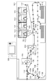
画像形成装置を図1に基づいて説明する。画像形成装置100は、プリント部101、操作部180を有する。プリント部101は、色成分毎の画像を形成する4つのステーション120、121、122、及び123を有する。ステーション120はイエローの画像を形成し、ステーション121はマゼンタの画像を形成し、ステーション122はシアンの画像を形成し、ステーション123はブラックの画像を形成する。
(Configuration of image forming apparatus)
The image forming apparatus will be described with reference to FIG. The image forming apparatus 100 has a
各ステーションは同一の構成であるので、以下ではイエローの画像を形成するステーション120の構成について説明する。感光ドラム105は、表面に感光層を有する感光体であり、帯電器111により帯電される。画像データに基づいて制御された露光装置103のレーザが感光ドラム105を走査することによって、感光ドラム105には静電潜像が形成される。現像器112は、トナーと、磁性を有するキャリアとを含む現像剤が収容される収容部と、前記収容部内に設けられ、現像剤を担持して回転駆動される現像スリーブ12とを有する。現像器112は、現像剤を用いて静電潜像を現像してトナー像を形成する。感光ドラム105は、プリント部101により形成された画像を担持する像担持体の一例である。また、帯電器111と露光装置103とは、静電潜像を形成する潜像形成手段として機能する。
Since each station has the same configuration, the configuration of the
一次転写ローラ118は、不図示の電源ユニットによって転写電圧が印加されると、感光ドラム105上のトナー像を中間転写ベルト106に転写する。各ステーション120、121、122、及び123により形成された色毎のトナー像が中間転写ベルト106に重ねて転写されることによって、中間転写ベルト106上にフルカラーのトナー像が担持される。中間転写ベルト106に担持されたトナー像は中間転写ベルト106が回転することによって二次転写ローラ114へと搬送される。中間転写ベルト106は、プリント部101により形成された画像を担持する転写体の一例である。
When a transfer voltage is applied by a power supply unit (not shown), the
中間転写ベルト106の周囲には、中間転写ベルト106上に形成された検知用画像からの反射光を検知するセンサ117が配置されている。画像形成装置100は、センサ117により検知された検知用画像からの反射光に基づいて、ステーション120、121、122、及び123により形成される画像の濃度が目標濃度となるように画像形成条件を補正する。
Around the
収容庫113に収容されたシート110は、中間転写ベルト106に担持されたトナー像とタイミングが合うように、搬送ローラ140aによって二次転写ローラ114へ向けて搬送される。二次転写ローラ114は、二次転写ローラ114に転写電圧が印加され、中間転写ベルト106に担持されたトナー像をシート110に転写する。そして、トナー像が転写されたシート110は定着器150、及び160へと搬送される。
The
定着器150、及び160は、シート110に転写されたトナー像を加熱および加圧してシート110に定着させる。定着器150は、シート110を加熱するヒータを有する定着ローラ151と、シート110を定着ローラ151に圧接させる加圧ベルト152とを備える。定着器160は、定着器150よりもシート110の搬送方向で下流に配置されている。定着器160は、定着器150を通過したシート110上のトナー像に対してグロス(光沢)を付与する。定着器160は、シートを加熱するヒータを有する定着ローラ161と、加圧ローラ162とを備える。
The
グロスを付与するモードにおいてシート110に画像を定着させる場合や、厚紙などの定着に必要な熱量が大きなシート110に画像を定着させる場合には、定着器150を通過したシート110は定着器160へと搬送される。普通紙や薄紙などのシート110に画像を定着させる場合には、定着器150を通過したシート110は定着器160を迂回する搬送路130に沿って搬送される。なお、定着器160にシート110を搬送するか、定着器160を迂回してシート110を搬送するかを制御するために、フラッパ131の角度が制御される。
When the image is fixed on the
フラッパ132は、シート110を搬送路135へと誘導するか、排出用の搬送路139に誘導するかを切り替える誘導部材である。搬送路135に沿って搬送されたシート110は反転部136へ搬送される。搬送路135に設けられた反転センサ137がシート110の後端を検出すると、シート110の搬送方向が反転される。
The
フラッパ133は、両面画像形成用の搬送路138へと誘導するか、搬送路135に誘導するかを切り替える誘導部材である。フェイスダウンモードが実行された場合、シート110は再び搬送路135へと搬送され、画像形成装置100から排出される。
The
一方、両面印刷モードが実行された場合、シート110は、搬送路138に沿って、再び転写ローラ114へと搬送される。両面印刷モードが実行された場合には、シート110の第1面に画像が定着された後、当該シート110が反転部136においてスイッチバックされ、搬送路138に沿って二次転写ローラ114へと搬送され、シート110の第2面に画像が形成される。
On the other hand, when the double-sided printing mode is executed, the
フラッパ134は、シート110を画像形成装置100から排出するための搬送路に誘導する誘導部材である。フェイスダウンモードにおいてシート110を排出する場合には、反転部136においてスイッチバックされたシートをフラッパ134が排出用の搬送路へと誘導する。排出用の搬送路に沿って搬送されたシート110は、画像形成装置100から排出される。
The
搬送路135には、シート110上の測定用画像の濃度を測定するカラーセンサ200が配置されている。搬送ローラ140bは搬送路135に沿ってシート110を搬送する。カラーセンサ200は、シート110の搬送方向に直交する方向に2つ並べて配置されており、2列の測定用画像を検知できる。
A
操作部180は、操作部としての液晶ディスプレイと、キー入力部とを有している。操作部180は、画像の印刷枚数や印刷モードをユーザが入力するインターフェースである。ユーザは、操作部180を用いて、片面印刷モードと両面印刷モードとを選択したり、フェイスダウンモードを実行したり、モノクロモードとカラーモードとを選択できる。
The
図2はカラーセンサ200の構造を示す図である。白色LED201は、シート110上の測定用画像220に光を照射する発光素子である。回折格子202は測定用画像220から反射した光を波長ごとに分光する分光部品である。ラインセンサ203は、回折格子202により波長ごとに分解された光を検出するn個の受光素子を備えた光検出素子である。
FIG. 2 is a diagram showing the structure of the
演算部204は、ラインセンサ203により検出された各画素の光強度値から各種の演算を行う。メモリ205は、演算部204が使用する各種のデータを保存する。演算部204は、例えば、光強度値から分光演算したり、又は、Lab値を演算する。カラーセンサ200により測定されるデータは、例えば、分光データ、色度データ、あるいは濃度データである。本実施形態のカラーセンサ200は、分光データ(L*、a*、b*)を出力する。
The
また、カラーセンサ200は、白色LED201から照射された光をシート110上の測定用画像220に集光したり、測定用画像220から反射した光を回折格子202に集光したりするレンズ206がさらに設けられてもよい。
Further, the
(制御ブロック図)
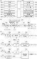
画像形成装置100の制御ブロック図を図3に基づいて説明する。CPU300は画像形成装置100の各部を制御する制御回路である。ROM301は、CPU300により実行される、後述のフローチャートの各種処理等を実行するために必要な制御プログラムが記憶されている。RAM302はCPU300が動作するためのシステムワークメモリである。
(Control block diagram)
The control block diagram of the image forming apparatus 100 will be described with reference to FIG. The
ハードディスク(HDD)303は、印刷ジョブに含まれる画像データ、階調補正テーブル(γLUT)、各種カラーチャートを記憶する。なお、本実施形態の画像形成装置100はHDD303を備える構成としたが、HDD303の代わりにSDカード又はフラッシュメモリといった外部記憶装置が接続されてもよい。
The hard disk (HDD) 303 stores image data included in the print job, a gradation correction table (γLUT), and various color charts. Although the image forming apparatus 100 of the present embodiment is configured to include the
インターフェース(I/F)304は、外部装置が接続され、当該接続された外部装置と通信を行う。I/F304は、例えばUSB端子接続可能なポートである。以下の説明においては、外部装置として測色デバイス400が接続される。I/F304は、測色デバイス400の動作指示の送信と測色デバイス400の測定結果の受信を行う。つまり、I/F304は、測色デバイス400の測定結果に対応する測定データを取得する。
The interface (I / F) 304 is connected to an external device and communicates with the connected external device. The I /
モータ305は、搬送路に設けられた搬送ローラ140a、及び140bやフラッパを駆動するための駆動源である。プリント部101、操作部180、カラーセンサ200は既に説明しているので、ここでの説明は省略する。
The
画像形成装置100が画像を形成するときの画像処理について以下に説明する。画像形成装置100がカラー画像を形成する場合、不図示のホストコンピュータから画像データ(RGB信号値)が入力される。なお、画像データは、JapanColorなどの標準印刷CMYK信号値を想定した画像信号であってもよい。 Image processing when the image forming apparatus 100 forms an image will be described below. When the image forming apparatus 100 forms a color image, image data (RGB signal values) is input from a host computer (not shown). The image data may be an image signal assuming a standard print CMYK signal value such as JapanColor.
カラーマネジメントモジュール(CMM)306は、RGB→L*a*b*変換またはCMYK→L*a*b*変換を実行する。さらにCMM306は、プロファイルデータ(入力用プロファイル)に基づいて色変換を実行する。プロファイルは、画像データの入力画像信号のガンマをコントロールする1次元LUT(ルックアップテーブル)、ダイレクトマッピングといわれる多次色LUT、生成された変換データのガンマをコントロールする1次元LUTなどである。これらのテーブルにより、入力画像信号は、デバイスに依存した色空間からデバイスに依存しない画像データ(L*a*b*)に変換される。プロファイルは、入力色空間を出力色空間へ変換するための色変換条件に対応する。
The color management module (CMM) 306 executes RGB → L * a * b * conversion or CMYK → L * a * b * conversion. Further, the
カラーマネジメントモジュール(CMM)306は、L*a*b*表色系に変換された画像データに対して、GAMUT変換や、光源種ミスマッチ(色温度設定のミスマッチとも言う)色変換などを実行する。GAMUT変換は、入力色空間と、画像形成装置100の出力色再現範囲と間のミスマッチをマッピングする。これによって、画像データの入力色空間が出力色空間へ変換される。光源種ミスマッチ色変換は、入力時の光源種と出力物を観察するときの光源種とのミスマッチを調整するための色変換である。これにより、画像データ(L*a*b*)は画像データ(L*’a*’b*’)へ変換される。画像データ(L*’a*’b*’)は、プロファイルデータ(出力用プロファイル)に基づいて色変換される。これにより、画像データ(L*’a*’b*’)は、出力機器(画像形成装置100)に依存したCMYK信号へと変換され、階調補正部307へ出力される。
The color management module (CMM) 306 executes GAMUT conversion, light source type mismatch (also called color temperature setting mismatch) color conversion, and the like on the image data converted to the L * a * b * color system. .. The GAMUT conversion maps a mismatch between the input color space and the output color gamut of the image forming apparatus 100. As a result, the input color space of the image data is converted into the output color space. The light source type mismatch color conversion is a color conversion for adjusting the mismatch between the light source type at the time of input and the light source type at the time of observing the output. As a result, the image data (L * a * b *) is converted into the image data (L *'a *'b *'). The image data (L *'a *'b *') is color-converted based on the profile data (output profile). As a result, the image data (L *'a *'b *') is converted into a CMYK signal depending on the output device (image forming apparatus 100) and output to the
階調補正部307は、入力された画像データ(CMYK信号)に種々の画像処理を施して、画像データを補正する。プリント部101により形成される画像(出力画像)の濃度は所望の濃度とならない。そこで、階調補正部307は、プリント部101により形成される出力画像の濃度が所望の濃度になるように、画像データの入力値(画像信号値)を補正する。階調補正部307は、例えば、HDD303に記憶された階調補正テーブル(γLUT)に基づいて画像データを補正する。HDD303には、階調補正テーブルが色毎に記憶されている。階調補正テーブル(γLUT)は、画像データを補正する階調補正条件に相当する。
The
CMM306により変換された画像データは、階調補正部307を介して、プリント部101に入力される。プリント部101は、入力された画像データに基づいて画像をシート110上に形成する。
The image data converted by the
パターンジェネレータ309は測定用画像データをプリント部101へ出力する。プリント部101は、パターンジェネレータ309から出力された測定用画像データに基づいて、シート110にカラーチャートを形成する。本実施形態に記載の画像形成装置100は複数の種類のカラーチャートを形成可能である。本実施形態の画像形成装置100は、少なくとも3種類のカラーチャート(カラーチャートA、B、及びC)を形成する。カラーチャートA、B、及びCの各々はパターン画像に相当する。
The
プロファイル作成部310は、多次色の変動を抑えるための多次元LUTであるプロファイルを作成するキャラクタライゼーション(多次色CAL)を行う。本実施形態のプロファイル作成部310は、例えば、ICC(International Color Consortium)プロファイルを作成する。なお、プロファイル作成部310は、ICCプロファイル以外のカラーマッチングプロファイルを作成する構成としてもよい。プロファイル作成部310によるプロファイル作成処理は、例えば、特開2009−004865号公報に記載されている。従って、プロファイル作成処理の説明は省略する。
The
ここで、カラーセンサ200とは異なる測色デバイス400を用いて、画像形成装置100によりシート110に印刷される画像(出力画像)の色味を調整するキャリブレーション処理を実行したいユーザがいる。なお、測色デバイス400は、例えば、分光データ(L*、a*、b*)を測定する分光センサである。測色デバイス400は、例えば、X−Rite社製のi1Pro2(登録商標)とする。
Here, there is a user who wants to execute a calibration process for adjusting the tint of an image (output image) printed on the
ユーザが測色デバイス400を用いてキャリブレーション処理を実行する場合、ユーザは手動で測色デバイス400を操作しなければならない。そこで、本実施形態の画像形成装置100は、変換部320がカラーセンサ200の測定結果を測色デバイス400の測定データへ変換可能とした。
When the user performs the calibration process using the
これによって、画像形成装置100はカラーセンサ200の測定結果から任意の測色デバイス400の測定結果をシミュレーションできる。そのため、ユーザは、キャリブレーション処理を実行する度に測色デバイス400の面倒な操作を実行する必要なくなる。
As a result, the image forming apparatus 100 can simulate the measurement result of any
また、測色デバイス400の測定データとカラーセンサ200の測定結果との相関関係が変化する可能性がある。そこで、画像形成装置100は前述の変換テーブルを更新する更新処理を実行する。変換条件生成部330は、測色デバイス400による共通チャートの測定結果とカラーセンサ200による共通チャートの測定結果とに基づいて、前述の変換テーブルを生成する。共通チャートは第2パターン画像に相当する。
In addition, the correlation between the measurement data of the
図4は、カラーセンサ200がカラーチャートを測定する様子を説明するための模式図である。カラーセンサ200は、画像形成装置100の搬送路135に配置される。カラーセンサ200は、カラーセンサ200a、及びカラーセンサ200bを含む。しかしながら、カラーセンサ200の数は、1個であってもよく、あるいは3個以上あってもよい。図4において矢印はシート110の搬送方向を示す。
FIG. 4 is a schematic diagram for explaining how the
本実施形態のカラーチャートBは、シート110が搬送される方向に直交する方向において異なる位置に形成されたカラーチャートB1とカラーチャートB2とを含む。カラーチャートBが印刷されたシート110がカラーセンサ200の測定位置を通過する際に、カラーセンサ200aはカラーチャートB1を測定し、カラーセンサ200bはカラーチャートB2を測定する。なお、カラーチャートBは第1パターン画像に相当する。
The color chart B of the present embodiment includes a color chart B1 and a color chart B2 formed at different positions in a direction orthogonal to the direction in which the
図5は、測色デバイス400がカラーチャートを測定する様子を説明するための模式図である。図5に示す矢印は、ユーザが測色デバイス400を移動させる移動方向である。
FIG. 5 is a schematic diagram for explaining how the
測色デバイス400は、画像形成装置100とUSBケーブルを介して接続され、ユーザがカラーチャート上の測定点へ測色デバイス400を移動させて、測定点の測定を行う。そのため、ユーザは、カラーチャートCが印刷されたシート110を水平な台に置き、測色デバイス400を、カラーチャートCに沿って移動させる。これによって、測色デバイス400はカラーチャートCの測定データを取得する。
The
本実施形態のカラーチャートCは、複数のカラーチャートC1、C2、及びC3を含む。カラーチャートC1、C2、及びC3は、シート110上の異なる位置に並んで形成される。なお、カラーチャートCは3列の測定用画像が配置された構成としたが、測定用画像の列の数は何列であってもよい。
The color chart C of the present embodiment includes a plurality of color charts C1, C2, and C3. The color charts C1, C2, and C3 are formed side by side at different positions on the
(キャリブレーション処理)
図6は、プロファイルを作成するキャリブレーション処理を示すフローチャートである。図6に示すフローチャートは、CPU300によりROM301に格納されたプログラムがRAM302に読み出され、CPU300によって実行される。図6に示すキャリブレーション処理は、ユーザが操作部180からキャリブレーション実行指示を入力すると開示される。
(Calibration process)
FIG. 6 is a flowchart showing a calibration process for creating a profile. In the flowchart shown in FIG. 6, the program stored in the
図10(a)は、キャリブレーション実行指示を受け付ける操作部180の画面の模式図である。画面901は、操作部180の液晶パネルに表示される。画像形成装置100は、キャリブレーションを実行するために必要な設定を画面901にてユーザから受け付ける。セル902は、キャリブレーションに用いるシートの種類(対象シート)を示す。ユーザがセル902を選択すると、プルダウンメニューが展開される。プルダウンメニューには、予め記憶された複数の紙種が選択可能に表示される。対象シートは、例えば、シート110の種類や坪量に応じて異なる。セル903は、対象シートの給紙元を示す。ユーザがセル903を選択すると、プルダウンメニューが展開される。プルダウンメニューには、例えば、手差しトレイや収容庫113が表示される。
FIG. 10A is a schematic view of the screen of the
チェックボックス904は、カラーセンサ200を用いたキャリブレーションを実行するか否かを選択するためのチェックボックスである。チェックボックス904がチャックされている場合、キャリブレーション処理において画像形成装置100がシート110にカラーチャートBを形成する。この場合、カラーチャートBの印刷されたシート110が画像形成装置100から排出される前にカラーセンサ200による測定動作が実行される。
The
一方、チェックボックス904がチャックされていない場合、キャリブレーション処理において画像形成装置100がシート110にカラーチャートCを形成する。この場合、カラーチャートCの印刷されたシート110が画像形成装置100から排出されてもカラーセンサ200による測定動作は実行されない。
On the other hand, when the
実行ボタン905はキャリブレーション処理の実行を指示するボタンである。ユーザが実行ボタン905を押下すると、CPU300が図6に示すフローチャートの処理を開始する。キャンセルボタン906はキャリブレーション処理のキャンセルを指示するボタンである。キャンセルボタン906が押下されると、CPU300はキャリブレーション処理を実行せずに、操作部180に表示された画面901がホーム画面に切り替わる。
The
ステップS501において、CPU300は、画面901において受け付けたキャリブレーション実行に必要な設定情報を取得する。次いで、ステップS502において、CPU300は、カラーセンサ200を用いたキャリブレーション処理を実行するか否かを判定する。チェックボックス904がチェックされている場合、CPU300は処理をステップS503へ移行する。
In step S501, the
ステップS503において、CPU300は、対象シートの変換テーブルが生成済みか否かを判定する。ステップS503において、CPU300は、HDD303に対象シートに対応する測色デバイス400用の補正情報(変換テーブル)が記憶されている場合、対象シートの変換テーブルが生成済みであると判定する。対象シートの変換テーブルとは、カラーセンサ200による対象シート上の測定用画像の測定結果と測色デバイス400による対象シート上の測定用画像の測定結果との相関データである。
In step S503, the
一方、ステップS503において、HDD303に測色デバイス400用の補正情報(変換テーブル)が記憶されていない場合、CPU300は対象シートの変換テーブルが生成されていないと判定する。
On the other hand, in step S503, when the correction information (conversion table) for the
図10(b)は、対象シートにおいてカラーセンサ200と測色デバイス400との相関データを補正するための変換テーブルが生成されていない場合、操作部180に表示される画面911の模式図である。対象シートにおいてセンサ間の補正情報が存在しない場合、CPU300は操作部180に画面911を表示して、補正情報を生成する必要があることを通知する。ユーザがボタン912を押下すると、CPU300は処理をステップS504へ移行する。ステップS504における補正情報の生成処理は図7を用いて後述する。
FIG. 10B is a schematic view of the
また、ステップS503において、HDD303に対象シートに対応する測色デバイス400用の補正情報(変換テーブル)が記憶されていた場合、CPU300は処理をステップS505へ移行する。ステップS505において、CPU300は第1キャリブレーション処理を実行する。第1キャリブレーション処理は、シート110に形成されたカラーチャートBをカラーセンサ200が測定した結果に基づいてプロファイルを作成する処理である。これによって、HDD303には新たにプロファイルが格納される。CPU300はプロファイルの作成を完了すると、本キャリブレーション処理を終了する。
Further, in step S503, when the correction information (conversion table) for the
また、ステップS502において、チェックボックス904がチェックされない場合、CPU300は処理をステップS506へ移行する。ステップS506において、CPU300は第2キャリブレーション処理を実行する。第2キャリブレーション処理は、シート110に形成されたカラーチャートCを測色デバイス400が測定した結果に基づいてプロファイルを作成する処理である。これによって、HDD303には新たにプロファイルが格納される。CPU300はプロファイルの作成を完了すると、本キャリブレーション処理を終了する。
If the
(センサ補正係数作成処理)
図7は、補正情報の生成処理を示すフローチャート図である。以下、ステップS504にて実行される補正情報の生成処理(センサ補正係数生成処理)を図3(d)と図7とに基づいて説明する。
(Sensor correction coefficient creation process)
FIG. 7 is a flowchart showing a correction information generation process. Hereinafter, the correction information generation process (sensor correction coefficient generation process) executed in step S504 will be described with reference to FIGS. 3 (d) and 7.
センサ補正係数生成処理が実行されると、ステップS601において、CPU300は、プリント部101を制御してカラーチャートA(共通チャート)をシート110に形成する。CPU300は、パターンジェネレータ309を制御して、カラーチャートAに対応する測定用画像データを階調補正部307を介してプリント部101へ転送する。これによって、プリント部101は測定用画像データに基づきカラーチャートAをシート110に形成する。カラーチャートAは、カラーセンサ200及び測色デバイス400の両センサで読取り可能なカラーチャートである。カラーチャートA(共通チャート)のレイアウトは図11を用いて後述する。
When the sensor correction coefficient generation process is executed, in step S601, the
次いで、CPU300は、ステップS602において、カラーチャートAが形成されたシート110を搬送路135へ誘導し、カラーセンサ200によってカラーチャートAの分光データを測定する。カラーセンサ200により取得された分光データは変換条件生成部330へ送信される。
Next, in step S602, the
次いで、CPU300は、ステップS603において、I/F304を介して測色デバイス400の測定データ(第2測定データ)が入力されるまで待機する。CPU300は、ステップS603において、カラーチャートAの測定手順を説明するためのガイダンスを操作部180の液晶画面に表示する。
Next, in step S603, the
図10(c)は、ユーザへ測定手順を説明するために液晶画面に表示される画面921の模式図である。画面921は、画面911において「次へ」ボタン912が押下され、ステップS601、及びS602の処理が完了した後に操作部180が液晶画面に表示される。ユーザは、画面921のガイダンスに従いカラーチャートAを測定する。カラーチャートCの測定が完了すると、ユーザはボタン922を押下する。CPU300は、ボタン922が押下された後、処理をステップS604へ移行する。
FIG. 10 (c) is a schematic view of a
ステップS604において、変換条件生成部330は、ステップS602、及びS603にて取得されたカラーセンサ200によるカラーチャートAの測定結果と測色デバイス400によるカラーチャートAの測定結果とに基づいて補正係数を算出する。
In step S604, the conversion
補正係数の算出方法の一例を以下に示す。変換条件生成部330は、測定用画像毎に分光データの相関を求める。
ΔL=L2*−L1* (1)
Δa=a2*−a1* (2)
Δb=b2*−b1* (3)
An example of the calculation method of the correction coefficient is shown below. The conversion
ΔL = L2 * -L1 * (1)
Δa = a2 * -a1 * (2)
Δb = b2 * −b1 * (3)
ここで、カラーセンサ200により取得された分光データを(L1*,a1*,b1*)、測色デバイス400により取得された分光データを(L2*,a2*,b2*)とする。相関データ(ΔL,Δa,Δb)は補正係数である。
Here, the spectroscopic data acquired by the
次いで、ステップS605において、CPU300は、ステップS604にて算出された補正係数をHDD303に保存する。そして、CPU300は、補正係数が登録されたことを操作部180の液晶画面に表示させ、センサ補正係数生成処理を終了する。
Next, in step S605, the
図10(d)は、センサ補正係数作成処理が完了した後に操作部180に表示される画面931の模式図である。画面931には、対象シートに対応するセンサ補正係数が正常に作成されたこと、及び、第1キャリブレーション処理(S505)が自動で実行されることをユーザに通知するためのメッセージが表示される。そして、ユーザがボタン932を押下すると、CPU300は操作部180の液晶画面にホーム画面を表示させる。
FIG. 10D is a schematic view of the
(第1キャリブレーション処理)
図3(c)と図8とを用いて、ステップS505にて実行される第1キャリブレーション処理について説明する。
(1st calibration process)
The first calibration process executed in step S505 will be described with reference to FIGS. 3C and 8.
ステップS701において、CPU300は、プリント部101を制御してシート110にカラーチャートBを形成する。CPU300は、パターンジェネレータ309を制御して、カラーチャートBに対応する測定用画像データを階調補正部307を介してプリント部101へ転送する。これによって、プリント部101は測定用画像データに基づきカラーチャートBをシート110に形成する。カラーチャートBは、カラーセンサ200用のカラーチャートである。カラーチャートBのレイアウトは図11を用いて後述する。
In step S701, the
次いで、ステップS702において、CPU300はモータ305を制御してカラーチャートBを搬送路135へ搬送させ、カラーセンサ200を制御してカラーチャートBを測定する。カラーセンサ200によるカラーチャートBの測定結果は、変換部320へ転送される。
Next, in step S702, the
ステップS703において、変換部320は、ステップS702にて取得された測定結果を、HDD303に記憶された補正係数(ΔL,Δa,Δb)に基づいて補正する。変換部320は、以下の演算処理を実行し、カラーセンサ200により取得された分光データ(L1*,a1*,b1*)を測色デバイス400の分光データ(L12*,a12*,b12*)へ変換する。分光データ(L12*,a12*,b12*)は第1測定データに相当する。
L12*=L1*+ΔL (4)
a12*=a1*+Δa (5)
b12*=b1*+Δb (6)
In step S703, the
L12 * = L1 * + ΔL (4)
a12 * = a1 * + Δa (5)
b12 * = b1 * + Δb (6)
そして、分光データ(L12*,a12*,b12*)はプロファイル作成部310へ転送される。ステップS704において、プロファイル作成部310は、カラーチャートBから取得された複数の測定用画像毎の分光データ(L12*,a12*,b12*)に基づいてプロファイルを生成する。
Then, the spectroscopic data (L12 *, a12 *, b12 *) is transferred to the
次いで、ステップS705において、CPU300は、ステップS704においてプロファイル作成部310により生成されたプロファイルをHDD303に保存する。そして、CPU300は、第1キャリブレーション処理を完了する。
Next, in step S705, the
(第2キャリブレーション処理)
次に、図3(c)と図9とを用いて、ステップS506にて実行される第2キャリブレーション処理について説明する。
(Second calibration process)
Next, the second calibration process executed in step S506 will be described with reference to FIGS. 3C and 9.
ステップS801において、CPU300は、プリント部101を制御してシート110にカラーチャートCを形成する。CPU300は、パターンジェネレータ309を制御して、カラーチャートCに対応する測定用画像データを階調補正部307を介してプリント部101へ転送する。これによって、プリント部101は測定用画像データに基づきカラーチャートCをシート110に形成する。カラーチャートCは、測色デバイス400用のカラーチャートである。カラーチャートCのレイアウトは図11を用いて後述する。なお、第2キャリブレーション処理を実行する場合、カラーセンサ200はカラーチャートCを測定しない。
In step S801, the
次いで、ステップS802において、CPU300は、I/F304を介して測色デバイス400によるカラーチャートCの分光データ(L2*,a2*,b2*)が入力されるまで待機する。ステップS802において、CPU300は、操作部180に表示された画面921のボタン922が押された場合、分光データ(L2*,a2*,b2*)が入力されたと判定する。そして、CPU300は、処理をステップS803へ移行する。
Next, in step S802, the
ステップS803において、分光データ(L2*,a2*,b2*)はプロファイル作成部310へ転送される。そして、プロファイル作成部310は、カラーチャートCから取得された複数の測定用画像毎の分光データ(L2*,a2*,b2*)に基づいてプロファイルを作成する。
In step S803, the spectroscopic data (L2 *, a2 *, b2 *) is transferred to the
次いで、ステップS804において、CPU300は、ステップS803においてプロファイル作成部310により生成されたプロファイルをHDD303に保存する。そして、CPU300は、第2キャリブレーション処理を完了する。
Next, in step S804, the
(カラーチャートの説明)
図7、図8、及び図9において画像形成装置100によりシート110に形成されるカラーチャートを、図11を用いて説明する。図11(a)、及び図11(b)に示すカラーチャート(カラーチャートA、及びB)は、HDD303に保存されている。そして、CPU300は、必要に応じてHDD303からカラーチャートを形成するための測定用画像データを読み出し、パターンジェネレータ309へ転送する。
(Explanation of color chart)
The color chart formed on the
図11(a)は、本実施形態のカラーチャート(共通チャート)Aのレイアウトの一例である。以下、カラーチャートAが形成されたシート110をテストシート1001と称す。テストシート1001の特徴は、以下の通りである。
FIG. 11A is an example of the layout of the color chart (common chart) A of the present embodiment. Hereinafter, the
測定用画像列1002がカラーセンサ200の個数と同じである。測定用画像列1002には複数の測定用画像が並んでいる。測定用画像列1002の1つに形成された測定用画像の数は、例えば、16個とする。
The
さらに、テストシート1001において、搬送方向における測定用画像(第2測定用画像)の長さ1003は、カラーセンサ200及び測色デバイス400が測定用画像を測定可能な長さよりも長い。測定用画像の長さ1003は、例えば、22[mm]とする。A3サイズのシート110に形成可能な測定用画像の数は、例えば、32個である。
Further, in the
図11(b)は、本実施形態のカラーチャートBのレイアウトの一例である。以下、カラーチャートBが形成されたシート110をテストシート1011と称す。テストシート1011の特徴は、以下の通りである。
FIG. 11B is an example of the layout of the color chart B of the present embodiment. Hereinafter, the
測定用画像列1012がカラーセンサ200の個数と同じである。測定用画像列1012には複数の測定用画像が並んでいる。測定用画像列1012の1つに形成された測定用画像の数は、例えば、19個とする。
The
さらに、測定用画像列1012には、搬送方向の長さが異なる測定用画像を含む。本実施形態においては、2種類の長さを有する測定用画像が含まれる。テストシート1011において、搬送方向における測定用画像(第1測定用画像)の長さ1013、及び1014は、カラーセンサ200が測定用画像を測定可能な長さより長い。
Further, the
搬送方向における測定用画像の長さ1013は、例えば、14[mm]である。搬送方向における測定用画像の長さ1014は、例えば、20[mm]である。カラーセンサ200は、テストシート1011が搬送されている間に複数の測定用画像を測定する。搬送ローラ140a、及び140bは、所定の回転速度にて回転している。しかしながら、搬送ローラ140a、及び140bによるシート110の搬送ムラが存在する。従って、搬送方向においてテストシート1011の先端側の測定用画像の寸法(長さ)に対して、搬送方向においてテストシート1011の後端側の測定用画像の寸法(長さ)を長くしている。これによって、搬送方向においてテストシート1011上に形成可能な測定用画像の数が担保される。
The
図11(c)は、本実施形態のカラーチャートCのレイアウトの一例である。以下、カラーチャートCが形成されたシート110をテストシート1021と称す。テストシート1021の特徴は、以下の通りである。
FIG. 11C is an example of the layout of the color chart C of the present embodiment. Hereinafter, the
測定用画像列1022には複数の測定用画像が並んでいる。測定用画像列1022の1つに形成された測定用画像の数は、例えば、20個とする。さらに、テストシート1021上の測定用画像の寸法は、測色デバイス400が測定可能な寸法以上であればよい。なお、ユーザが測色デバイス400を手動で移動させるので、テストシート1021上の測定用画像の寸法1023は、例えば、10[mm]とする。つまり、A3サイズのシート110に形成可能な測定用画像の数は、他のカラーチャート(カラーチャートA、及びB)に比べて多い。そのため、第1、及び第2キャリブレーション処理において測定される測定用画像の数を同じとするならば、第2キャリブレーション処理において必要なシート110の枚数は第1キャリブレーション処理において必要なシート110の枚数よりも少なくなる。
A plurality of measurement images are arranged in the
本発明によれば、カラーチャートを測定する測色デバイスに適したカラーチャートを形成することができる。 According to the present invention, it is possible to form a color chart suitable for a color measuring device for measuring a color chart.
また、テストシート1001に形成可能な測定用画像の数は、テストシート1011に形成可能な測定用画像の数より少ない。さらに、テストシート1001に形成可能な測定用画像の数は、テストシート1021に形成可能な測定用画像の数より少ない。
Further, the number of measurement images that can be formed on the
また、上記説明において、テストシート1001上の測定用画像の長さ1003は、テストシート1011上の測定用画像の長さ1014より長くしているが、測定用画像の長さ1003と測定用画像の長さ1014とを同じ長さとしてもよい。
In the above description, the
101 プリント部
140a、140b 搬送ローラ
200 カラーセンサ
306 CMM
310 プロファイル作成部
320 変換部
330 変換条件生成部
101
310
Claims (6)
画像データを色変換条件に基づいて変換する色変換手段と、
前記変換された前記画像データに基づいて、前記シートに画像を形成する画像形成手段と、
前記搬送路に設けられ、前記シート上の測定用画像を測定する測定手段と、
前記測定手段の測定結果を変換条件に基づいて変換する変換手段と、
前記搬送手段を制御して前記シートを搬送させ、前記画像形成手段を制御して前記シートに複数の第1測定用画像を含む第1パターン画像を形成させ、前記測定手段を制御して前記シート上の前記複数の第1測定用画像を測定させ、前記変換手段によって前記複数の第1測定用画像の測定結果を第1測定データに変換させ、前記色変換条件を前記第1測定データに基づいて生成する第1生成手段と、
前記搬送手段を制御して前記シートを搬送させ、前記画像形成手段により前記シートに複数の第2測定用画像を含む第2パターン画像を形成させ、前記測定手段を制御して前記シート上の前記複数の第2測定用画像を測定させ、外部センサから出力された前記シート上の前記複数の第2測定用画像の測定結果に対応する第2測定データを取得し、前記測定手段による前記複数の第2測定用画像の測定結果と前記第2測定データとに基づいて前記変換条件を生成する第2生成手段と、を有し、
前記複数の第1測定用画像は、前記シートが搬送される搬送方向の長さが第1の長さになるように前記シートに形成される第1測定用画像と、前記搬送方向の長さが前記第1の長さより長い第2の長さとなるように前記シートに形成される第1測定用画像とを有し、
前記第1の長さになるように前記シートに形成される前記第1測定用画像の位置と前記第2の長さとなるように前記シートに形成される前記第1測定用画像の位置とは前記搬送方向において異なっており、
前記搬送方向の長さが前記第2の長さとなるように前記シートに形成される前記第1測定用画像は、前記複数の第1測定用画像の前記測定結果を取得するために前記測定手段が前記複数の第1測定用画像を測定する際に前記搬送方向において前記複数の第1測定用画像のなかで最も後端に位置しており、
前記複数の第2測定用画像の各々は、前記搬送方向の長さが前記第2の長さ以上の第3の長さとなるように、前記搬送方向において前記シートの異なる位置に形成されることを特徴とする画像形成装置。 A transport means for transporting the sheet along the transport path, and
A color conversion means that converts image data based on color conversion conditions,
An image forming means for forming an image on the sheet based on the converted image data,
A measuring means provided in the transport path and measuring a measurement image on the sheet,
A conversion means that converts the measurement result of the measuring means based on the conversion conditions, and a conversion means.
The sheet is conveyed by controlling the conveying means, the image forming means is controlled to form a first pattern image including a plurality of first measurement images on the sheet, and the measuring means is controlled to convey the sheet. The plurality of first measurement images are measured, the measurement results of the plurality of first measurement images are converted into first measurement data by the conversion means, and the color conversion conditions are based on the first measurement data. And the first generation means to generate
The sheet is conveyed by controlling the conveying means, a second pattern image including a plurality of second measurement images is formed on the sheet by the image forming means, and the measuring means is controlled to convey the sheet on the sheet. A plurality of second measurement images are measured, second measurement data corresponding to the measurement results of the plurality of second measurement images on the sheet output from the external sensor is acquired, and the plurality of second measurement data by the measurement means are obtained. It has a second generation means for generating the conversion condition based on the measurement result of the second measurement image and the second measurement data.
The plurality of first measurement images are the first measurement image formed on the sheet so that the length in the transport direction in which the sheet is transported becomes the first length, and the length in the transport direction. Has a first measurement image formed on the sheet so that is a second length longer than the first length.
What is the position of the first measurement image formed on the sheet so as to have the first length and the position of the first measurement image formed on the sheet so as to have the second length? It is different in the transport direction
The first measurement image formed on the sheet so that the length in the transport direction is the second length is the measuring means for acquiring the measurement results of the plurality of first measurement images. Is located at the rearmost end of the plurality of first measurement images in the transport direction when measuring the plurality of first measurement images.
Each of the plurality of second measurement images is formed at different positions on the sheet in the transport direction so that the length in the transport direction is a third length equal to or greater than the second length. An image forming apparatus characterized by.
前記複数の他の測定用画像の各々は前記搬送方向の長さが前記第2の長さより短い所定の長さとなるように前記シートに形成されることを特徴とする請求項2に記載の画像形成装置。 The other pattern image is formed by arranging a plurality of other measurement images side by side in the transport direction.
The image according to claim 2, wherein each of the plurality of other measurement images is formed on the sheet so that the length in the transport direction is a predetermined length shorter than the second length. Forming device.
Priority Applications (2)
| Application Number | Priority Date | Filing Date | Title |
|---|---|---|---|
| JP2017108240A JP6914735B2 (en) | 2017-05-31 | 2017-05-31 | Image forming device |
| US15/986,624 US10401771B2 (en) | 2017-05-31 | 2018-05-22 | Image forming apparatus and control method which generates color processing condition |
Applications Claiming Priority (1)
| Application Number | Priority Date | Filing Date | Title |
|---|---|---|---|
| JP2017108240A JP6914735B2 (en) | 2017-05-31 | 2017-05-31 | Image forming device |
Publications (3)
| Publication Number | Publication Date |
|---|---|
| JP2018207225A JP2018207225A (en) | 2018-12-27 |
| JP2018207225A5 JP2018207225A5 (en) | 2020-07-30 |
| JP6914735B2 true JP6914735B2 (en) | 2021-08-04 |
Family
ID=64459772
Family Applications (1)
| Application Number | Title | Priority Date | Filing Date |
|---|---|---|---|
| JP2017108240A Active JP6914735B2 (en) | 2017-05-31 | 2017-05-31 | Image forming device |
Country Status (2)
| Country | Link |
|---|---|
| US (1) | US10401771B2 (en) |
| JP (1) | JP6914735B2 (en) |
Families Citing this family (4)
| Publication number | Priority date | Publication date | Assignee | Title |
|---|---|---|---|---|
| JP6914735B2 (en) * | 2017-05-31 | 2021-08-04 | キヤノン株式会社 | Image forming device |
| CN113518903B (en) * | 2019-03-05 | 2024-03-15 | 柯尼卡美能达株式会社 | Calibration system, calibration device, and program |
| JP2022123706A (en) * | 2021-02-12 | 2022-08-24 | セイコーエプソン株式会社 | Colorimetric method, and colorimetric system |
| WO2023234229A1 (en) * | 2022-06-03 | 2023-12-07 | 富士フイルム株式会社 | Information processing device, information processing method, and information processing program |
Family Cites Families (7)
| Publication number | Priority date | Publication date | Assignee | Title |
|---|---|---|---|---|
| JP2003065852A (en) | 2001-08-29 | 2003-03-05 | Canon Inc | Image processing method, device and program |
| JP2006065184A (en) * | 2004-08-30 | 2006-03-09 | Kyocera Mita Corp | Image forming apparatus |
| JP2009004865A (en) | 2007-06-19 | 2009-01-08 | Canon Inc | Method and device for preparing profile |
| JP5712971B2 (en) * | 2012-06-22 | 2015-05-07 | コニカミノルタ株式会社 | Image processing apparatus, image processing method, and printing system |
| JP6361626B2 (en) * | 2015-10-09 | 2018-07-25 | コニカミノルタ株式会社 | Image reading apparatus, image forming apparatus, image forming system, image forming method, and image forming control program |
| JP6300119B2 (en) * | 2015-11-05 | 2018-03-28 | コニカミノルタ株式会社 | Colorimetric value acquisition method, image forming apparatus, and colorimetric value acquisition control program |
| JP6914735B2 (en) * | 2017-05-31 | 2021-08-04 | キヤノン株式会社 | Image forming device |
-
2017
- 2017-05-31 JP JP2017108240A patent/JP6914735B2/en active Active
-
2018
- 2018-05-22 US US15/986,624 patent/US10401771B2/en active Active
Also Published As
| Publication number | Publication date |
|---|---|
| JP2018207225A (en) | 2018-12-27 |
| US20180348685A1 (en) | 2018-12-06 |
| US10401771B2 (en) | 2019-09-03 |
Similar Documents
| Publication | Publication Date | Title |
|---|---|---|
| JP5904784B2 (en) | Image forming apparatus | |
| US9031468B2 (en) | Image forming apparatus | |
| US9207125B2 (en) | Image forming apparatus | |
| US9066052B2 (en) | Image forming apparatus for forming a measurement image on a sheet | |
| JP6914735B2 (en) | Image forming device | |
| JP5950569B2 (en) | Image forming apparatus | |
| US9274464B2 (en) | Image forming apparatus | |
| JP6624842B2 (en) | Image forming device | |
| JP5905018B2 (en) | Image forming apparatus | |
| JP5888961B2 (en) | Image forming apparatus | |
| JP2014041203A (en) | Image forming device | |
| US20140050496A1 (en) | Image forming apparatus for forming a measurement image | |
| US20140255051A1 (en) | Image forming apparatus | |
| US20240022678A1 (en) | Information processing device and method of controlling image forming apparatus | |
| JP2014085502A (en) | Image forming apparatus | |
| US8948634B2 (en) | Image forming apparatus | |
| JP7140592B2 (en) | Measuring device, image forming device | |
| JP6061506B2 (en) | Image forming apparatus | |
| JP6679297B2 (en) | Image forming device | |
| US11093807B2 (en) | Image forming system | |
| JP2013080181A (en) | Image forming apparatus | |
| JP5924912B2 (en) | Image forming apparatus |
Legal Events
| Date | Code | Title | Description |
|---|---|---|---|
| A521 | Written amendment |
Free format text: JAPANESE INTERMEDIATE CODE: A523 Effective date: 20200528 |
|
| A621 | Written request for application examination |
Free format text: JAPANESE INTERMEDIATE CODE: A621 Effective date: 20200528 |
|
| A977 | Report on retrieval |
Free format text: JAPANESE INTERMEDIATE CODE: A971007 Effective date: 20210303 |
|
| A131 | Notification of reasons for refusal |
Free format text: JAPANESE INTERMEDIATE CODE: A131 Effective date: 20210316 |
|
| A521 | Written amendment |
Free format text: JAPANESE INTERMEDIATE CODE: A523 Effective date: 20210512 |
|
| TRDD | Decision of grant or rejection written | ||
| A01 | Written decision to grant a patent or to grant a registration (utility model) |
Free format text: JAPANESE INTERMEDIATE CODE: A01 Effective date: 20210615 |
|
| A61 | First payment of annual fees (during grant procedure) |
Free format text: JAPANESE INTERMEDIATE CODE: A61 Effective date: 20210714 |
|
| R151 | Written notification of patent or utility model registration |
Ref document number: 6914735 Country of ref document: JP Free format text: JAPANESE INTERMEDIATE CODE: R151 |