JP6914622B2 - Image forming device and image heating device - Google Patents
Image forming device and image heating device Download PDFInfo
- Publication number
- JP6914622B2 JP6914622B2 JP2016131620A JP2016131620A JP6914622B2 JP 6914622 B2 JP6914622 B2 JP 6914622B2 JP 2016131620 A JP2016131620 A JP 2016131620A JP 2016131620 A JP2016131620 A JP 2016131620A JP 6914622 B2 JP6914622 B2 JP 6914622B2
- Authority
- JP
- Japan
- Prior art keywords
- heating
- image
- region
- recording material
- heat
- Prior art date
- Legal status (The legal status is an assumption and is not a legal conclusion. Google has not performed a legal analysis and makes no representation as to the accuracy of the status listed.)
- Active
Links
Images


Description
本発明は、電子写真方式や静電記録方式を利用した複写機やプリンタ等の画像形成装置に関する。また、画像形成装置に搭載されている定着器や、記録材に定着されたトナー画像を再度加熱することによりトナー画像の光沢度を向上させる光沢付与装置、等の像加熱装置に関する。 The present invention relates to an image forming apparatus such as a copier or a printer using an electrophotographic method or an electrostatic recording method. The present invention also relates to an image heating device such as a fixing device mounted on an image forming device and a gloss imparting device for improving the glossiness of a toner image by reheating a toner image fixed on a recording material.
複写機やプリンタ等の電子写真画像形成装置(以下、画像形成装置)に用いられる定着器や、光沢付与装置等の像加熱装置において、省電力化の要請から、記録材上に形成された画像部を選択的に加熱する方式が提案されている(特許文献1)。この方式のヒータは、記録材の通紙方向に直交する方向(以下、長手方向という)において、複数に分割された加熱領域を設定し、それぞれの加熱領域を加熱する発熱体が長手方向に複数設けられている。そして、各加熱領域に形成される画像の画像情報に基づき、対応する発熱体により画像部が選択的に加熱される。また、画像情報に応じて加熱条件を調整し、省電力化を図る方法(特許文献2)を組合せて用いれば、更なる省電力化が可能となる。更に、像加熱装置の熱履歴に応じた加熱条件補正を、各加熱領域毎に適用し、より一層の省電力化を図ることも可能である。 An image formed on a recording material in a fixing device used in an electrophotographic image forming apparatus (hereinafter referred to as an image forming apparatus) such as a copier or a printer, or an image heating device such as a gloss imparting apparatus in response to a request for power saving. A method of selectively heating a portion has been proposed (Patent Document 1). In this type of heater, heating regions divided into a plurality of heating regions are set in a direction orthogonal to the paper passing direction of the recording material (hereinafter referred to as a longitudinal direction), and a plurality of heating elements for heating each heating region are provided in the longitudinal direction. It is provided. Then, based on the image information of the image formed in each heating region, the image portion is selectively heated by the corresponding heating element. Further, if the heating conditions are adjusted according to the image information and a method for reducing power consumption (Patent Document 2) is used in combination, further power saving can be achieved. Further, it is possible to further reduce power consumption by applying the heating condition correction according to the heat history of the image heating device for each heating region.
特許文献1や特許文献2に記載の方法を用いて、各加熱領域の画像に最適な加熱条件で各発熱体への通電制御を行えば、画像部に対する選択的加熱を行わない場合に比べて省電力化を図ることができる。しかしながら、各加熱領域において、加熱領域内に形成される画像に応じた加熱を続けていくと、像加熱装置の各加熱領域に相当する部分の暖まり具合(以下、蓄熱量と表記する)に差が生じる。蓄熱量を考慮せずに各加熱領域の加熱条件を設定すると、記録材上の未定着トナー像への適正な熱供給が行われず、これに起因する画像不良が生じることがある。また、省電力性の観点からも好ましくない。これに対応するため、各加熱領域の熱履歴からその加熱領域の蓄熱量を予測し、この蓄熱量に応じた各加熱領域における加熱条件補正を行うことも考えられる。
If the energization control of each heating element is performed under the optimum heating conditions for the image of each heating region by using the methods described in
しかしながら、一の加熱領域の蓄熱量は、その加熱領域の熱履歴だけで決まるものではなく、隣接する加熱領域から伝播する熱の影響、すなわち隣接する加熱領域の熱履歴の影響も受けることになる。従って、それぞれの加熱領域に対して予測した蓄熱量が、実際の蓄熱量と大きく異なる場合があり、必ずしも十分な予測精度が得られない可能性がある。 However, the amount of heat stored in one heating region is not determined only by the heat history of the heating region, but is also affected by the heat propagating from the adjacent heating region, that is, the heat history of the adjacent heating region. .. Therefore, the predicted heat storage amount for each heating region may differ significantly from the actual heat storage amount, and there is a possibility that sufficient prediction accuracy cannot always be obtained.
本発明の目的は、個々の加熱領域の蓄熱量をより精度良く予測し、より一層の省電力効果を得ることができる技術を提供することである。 An object of the present invention is to provide a technique capable of more accurately predicting the amount of heat stored in each heating region and obtaining a further power saving effect.
上記目的を達成するため、本発明の像加熱装置は、
第1回転体と、
前記第1回転体の外周面に接触する第2回転体であって、前記第1回転体との間にニップ部を形成する第2回転体と、
記録材の搬送方向及び記録材の厚み方向の両方向に対して直交する方向に複数の発熱ブロックが並んだヒータと、
前記複数の発熱ブロック毎の加熱条件を発熱ブロック毎に設定する制御部であって、第1の記録材上の画像部を加熱するときの前記発熱ブロックの加熱条件と、第1の記録材上の非画像部を加熱するときの前記発熱ブロックの加熱条件が異なるように設定する制御部と、を有し、
前記ヒータは、前記第1回転体の内部空間に配置されており、
前記ニップ部を記録材が通過することにより、記録材に形成された画像が加熱される像加熱装置であって、
前記ニップ部の領域のうち、前記複数の発熱ブロックのなかの第1発熱ブロックにより加熱される前記第1回転体の領域に対応する前記ニップ部の領域を第1加熱領域、前記ニップ部の領域のうち、前記複数の発熱ブロックのなかの前記第1発熱ブロックに隣接する第2発熱ブロックにより加熱される前記第1回転体の領域に対応する前記ニップ部の領域を第2加熱領域とすると、
前記制御部は、前記第1の記録材上の画像部のうち、前記第1加熱領域により加熱される第1の画像部の先端から後端までの距離に応じて、前記第1加熱領域における第1の蓄熱量を算出し、前記第1の記録材上の画像部のうち、前記第2加熱領域により加熱される第2の画像部の先端から後端までの距離に応じて、前記第2加熱領域における第2の蓄熱量を算出し、
前記第1の記録材の後に第2の記録材が前記ニップ部に搬送される場合、前記第1発熱ブロックの前記加熱条件を、前記第1の蓄熱量及び前記第2の蓄熱量に応じて設定することを特徴とする。
In order to achieve the above object, the image heating device of the present invention is used.
The first rotating body and
A second rotating body that comes into contact with the outer peripheral surface of the first rotating body and that forms a nip portion between the first rotating body and the second rotating body.
A heater in which a plurality of heat generating blocks are arranged in a direction orthogonal to both the transport direction of the recording material and the thickness direction of the recording material.
A control unit that sets the heating conditions for each of the plurality of heat generation blocks for each heat generation block, and the heating conditions for the heat generation block when heating the image unit on the first recording material and the heating conditions on the first recording material. It has a control unit that sets the heating conditions of the heat generating block to be different when heating the non-image part of the above.
The heater is arranged in the internal space of the first rotating body.
An image heating device that heats an image formed on a recording material by passing the recording material through the nip portion.
Among the regions of the nip portion, the region of the nip portion corresponding to the region of the first rotating body heated by the first heat generation block among the plurality of heat generation blocks is the first heating region and the region of the nip portion. Among the plurality of heat generation blocks, the region of the nip portion corresponding to the region of the first rotating body heated by the second heat generation block adjacent to the first heat generation block is defined as the second heating region.
Wherein, the first of the image portion on the recording material, according to the distance in the previous end or et after Tanma the first image portion to be heated by said first heating zone, the first calculating a first quantity of thermal storage in the heating region, the distance in the first of the image portion on the recording material, a second image of the previous edge if et after Tanma heated by the second heating region The second heat storage amount in the second heating region is calculated according to the above.
When the second recording material is conveyed to the nip portion after the first recording material, the heating conditions of the first heat generation block are set according to the first heat storage amount and the second heat storage amount. It is characterized by setting.
本発明によれば、個々の加熱領域の蓄熱量をより精度良く予測し、より一層の省電力効果を得ることができる。 According to the present invention, the amount of heat stored in each heating region can be predicted more accurately, and a further power saving effect can be obtained.
以下に図面を参照して、この発明を実施するための形態を、実施例に基づいて例示的に詳しく説明する。ただし、この実施の形態に記載されている構成部品の寸法、材質、形状それらの相対配置などは、発明が適用される装置の構成や各種条件により適宜変更されるべきものである。すなわち、この発明の範囲を以下の実施の形態に限定する趣旨のものではない。 Hereinafter, embodiments for carrying out the present invention will be described in detail exemplarily based on examples with reference to the drawings. However, the dimensions, materials, shapes, and relative arrangements of the components described in this embodiment should be appropriately changed depending on the configuration of the apparatus to which the invention is applied and various conditions. That is, it is not intended to limit the scope of the present invention to the following embodiments.
[実施例1]
1.画像形成装置の構成
図1は、本発明の実施例に係る電子写真方式の画像形成装置の構成図である。本発明が適用可能な画像形成装置としては、電子写真方式や静電記録方式を利用した複写機、プリンタなどが挙げられ、ここではレーザプリンタに適用した場合について説明する。
[Example 1]
1. 1. Configuration of Image Forming Device FIG. 1 is a configuration diagram of an electrophotographic image forming apparatus according to an embodiment of the present invention. Examples of the image forming apparatus to which the present invention can be applied include a copying machine and a printer using an electrophotographic method and an electrostatic recording method, and here, a case where the present invention is applied to a laser printer will be described.
画像形成装置100は、ビデオコントローラ120と制御部113を備える。ビデオコントローラ120は、記録材に形成される画像の情報を取得する取得部として、パーソナルコンピュータ等の外部装置から送信される画像情報及びプリント指示を受信して処理するものである。制御部113は、ビデオコントローラ120と接続されており、ビデオコントローラ120からの指示に応じて画像形成装置100を構成する各部を制御するものである。ビデオコントローラ120が外部装置からプリント指示を受けると、以下の動作で画像形成が実行される。
The
画像形成装置100は、記録材Pを給送ローラ102で給送して、中間転写体103に向けて搬送する。感光ドラム104は、図示しない駆動モータの動力によって所定の速度で反時計回り方向に回転駆動され、その回転過程で一次帯電器105によって一様に帯電処理される。画像信号に対応して変調されたレーザ光がレーザビームスキャナ106から出力され、感光ドラム104上を選択的に走査露光して静電潜像を形成する。107は現像器であり、静電潜像に現像剤である粉体トナーを付着させてトナー像(現像剤像)として可視像化する。感光ドラム104上に形成されたトナー像は、感光ドラム104と接触して回転する中間転写体103上に一次転写される。
The
ここで、感光ドラム104、一次帯電器105、レーザビームスキャナ106、現像器107は、シアン(C)、マゼンタ(M)、イエロー(Y)、ブラック(K)の4色分がそれぞれ配置されている。4色分のトナー像が同じ手順で順次中間転写体103上に重ねて転写される。中間転写体103上に転写されたトナー像は、中間転写体103と転写ローラ108で形成される二次転写部において、転写ローラ108に印加された転写バイアスにより記録材P上に二次転写される。上記構成において記録材P上へのトナー像の形成にかかわる構成が本発明における画像形成部に対応する。その後、像加熱装置としての定着装置200が記録材Pを加熱及び加圧することによりトナー像が記録材に定着され、画像形成物として機外へ排出される。
Here, the
制御部113は、記録材Pの搬送路上の、搬送センサ114、レジストセンサ115、定着前センサ116、定着排紙センサ117によって、記録材Pの搬送状況を管理する。加えて、制御部113は、定着装置200の温度制御プログラムおよび温度制御テーブルを記憶する記憶部を有する。商用の交流電源401に接続されたヒータ駆動手段としての制御回路400は、定着装置200への電力供給を行う。
The
2.定着装置(定着部)の構成
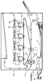
図2は、本実施例の定着装置200の模式的断面図である。定着装置200は、定着フィルム202と、定着フィルム202の内面に接触するヒータ300と、定着フィルム202を介してヒータ300と共に定着ニップ部Nを形成する加圧ローラ208と、を有する。
2. Configuration of Fixing Device (Fixing Section) FIG. 2 is a schematic cross-sectional view of the
定着フィルム202は、筒状に形成された可撓性を有する複層耐熱フィルムであり、厚みが50〜100μm程度のポリイミド等の耐熱樹脂、または厚みが20〜50μm程度のステンレス等の金属を基層として用いることができる。また、定着フィルム202の表面にはトナーの付着防止や記録材Pとの分離性を確保するための離型層が設けられている。離型層は、厚みが10〜50μm程度のテトラフルオロエチレン・パーフルオロアルキルビニルエーテル共重合体(PFA)等の離型性に優れた耐熱樹脂である。更に、カラー画像を形成する装置に用いる定着フィルムでは、画質向上のため、基層と離型層の間に、弾性層として、厚みが100〜400μm程度、熱伝導率が0.2〜3.0W/m・K程度のシリコーンゴム等の耐熱ゴムを設けても良い。本実施例では、熱応答性や画質、耐久性等の観点から、基層として厚み60μmのポリイミド、弾性層として厚み300μm、熱伝導率1.6W/m・Kのシリコーンゴム、離型層として厚み30μmのPFAを用い
ている。
The fixing
加圧ローラ208は、鉄やアルミニウム等の材質の芯金209と、シリコーンゴム等の材質の弾性層210を有する。ヒータ300は、耐熱樹脂製のヒータ保持部材201に保持されており、定着フィルム202を加熱する。ヒータ保持部材201は、定着フィルム202の回転を案内するガイド機能も有している。金属ステー204は、不図示の付勢部材等から加圧力を受けて、ヒータ保持部材201を加圧ローラ208に向けて付勢する。加圧ローラ208は、モータ30から動力を受けて矢印R1方向に回転する。加圧ローラ208が回転することによって、定着フィルム202が従動して矢印R2方向に回転する。定着ニップ部Nにおいて記録材Pを挟持搬送しつつ定着フィルム202の熱を与えることで、記録材P上の未定着トナー像は定着処理される。
The
ヒータ300は、セラミック製の基板305上に設けられた発熱体としての発熱抵抗体が通電によって発熱するヒータである。ヒータ300は、定着フィルム202の内面に接触する表面保護層308と、基板305の表面保護層308が設けられた側(以下、摺動面側と称する)とは反対側(以下、裏面側と称する)に設けられた表面保護層307を有する。ヒータ300の裏面側には給電用の電極(ここでは代表として電極E4を示してある)が設けられている。C4は電極E4に接触する電気接点であり、電気接点から電極に給電を行っている。ヒータ300の詳細は後述する。また、ヒータ300の異常発熱により作動してヒータ300に供給する電力を遮断するサーモスイッチや温度ヒューズ等の安全素子212が、ヒータ300の裏面側に対向して配置されている。
The
3.ヒータの構成
図3は、本発明の実施例1のヒータ300の構成を示す模式図である。
図3(a)は、図3(b)に示す搬送基準位置X付近におけるヒータの断面図である。搬送基準位置Xは、記録材Pを搬送する際の基準位置として定義する。本実施例の画像形成装置では、記録材Pの搬送方向に直交する幅方向における中央部が、搬送基準位置Xを通過するように記録材が搬送される。ヒータ300は、概略、基板305の一方の面(裏面)に2つの層(裏面層1、2)、他方の面(摺動面)にも2つの層(摺動面層1、2)がそれぞれ形成された5層構造を有する。
3. 3. Configuration of Heater FIG. 3 is a schematic view showing the configuration of the
FIG. 3A is a cross-sectional view of the heater in the vicinity of the transport reference position X shown in FIG. 3B. The transport reference position X is defined as a reference position when transporting the recording material P. In the image forming apparatus of this embodiment, the recording material is transported so that the central portion in the width direction orthogonal to the transport direction of the recording material P passes through the transport reference position X. The
ヒータ300は、基板305の裏面層側の面上にヒータ300の長手方向に沿って設けられている第1の導電体301(301a、301b)を有する。また、ヒータ300は、基板305上に第1の導電体301とヒータ300の短手方向(長手方向と直交する方向)に異なる位置でヒータ300の長手方向に沿って設けられている第2の導電体303(搬送基準位置X付近では303−4)を有する。第1の導電体301は、記録材Pの搬送方向の上流側に配置された導電体301aと、下流側に配置された導電体301bに分離されている。更に、ヒータ300は、第1の導電体301と第2の導電体303の間に設けられており、第1の導電体301と第2の導電体303を介して供給する電力により発熱する発熱抵抗体302を有する。
The
発熱抵抗体302は、本実施例では記録材Pの搬送方向の上流側に配置された発熱抵抗体302a(搬送基準位置X付近では302a−4)と、下流側に配置された発熱抵抗体302b(搬送基準位置X付近では302b−4)に分離されている。また、ヒータ300の裏面層2には、発熱抵抗体302、第1の導電体301、及び第2の導電体303を覆う絶縁性(本実施例ではガラス)の表面保護層307が、電極部(搬送基準位置X付近ではE4)を避けて設けられている。
In this embodiment, the heat-generating resistors 302 are the heat-generating
図3(b)には、ヒータ300の各層の平面図を示してある。ヒータ300の裏面層1には、第1の導電体301と第2の導電体303と発熱抵抗体302の組からなる発熱ブ
ロックがヒータ300の長手方向に複数設けられている。本実施例のヒータ300は、ヒータ300の長手方向に、合計7つの発熱ブロックHB1〜HB7を有する。発熱ブロックHB1の図中の左端から、発熱ブロックHB7の図中の右端までが発熱領域であり、その長さは220mmである。本例では各発熱ブロックの長手方向幅は全て同じである(必ずしもすべて同じ長手方向幅でなくても良い)。
FIG. 3B shows a plan view of each layer of the
発熱ブロックHB1〜HB7は、ヒータ300の短手方向に対称に形成された、発熱抵抗体302a−1〜302a−7及び発熱抵抗体302b−1〜302b−7によって、それぞれ構成されている。第1の導電体301は、発熱抵抗体(302a−1〜302a−7)と接続する導電体301aと、発熱抵抗体(302b−1〜302b−7)と接続する導電体301bによって構成されている。同様に、第2の導電体303は、7つの発熱ブロックHB1〜HB7に対応するため、7つの導電体303−1〜303−7に分割されている。
The heat generation blocks HB1 to HB7 are each composed of
電極E1〜E7、E8−1、及びE8−2は、電気接点C1〜C7、C8−1、C8−2に接続される。電極E1〜E7はそれぞれ、導電体303−1〜303−7を介して、発熱ブロックHB1〜HB7に電力供給するための電極である。電極E8−1、及びE8−2は、導電体301a、及び導電体301bを介して、7つの発熱ブロックHB1〜HB7に電力給電するための共通の電極である。本実施例では長手方向の両端に電極E8−1、及びE8−2を設けているが、例えば電極E8−1のみを片側に設ける構成(即ち、電極E8−2を設けない構成)でも良いし、電極E8−1と電極8−2を夫々記録材搬送方向において二つに分けても良い。
The electrodes E1 to E7, E8-1 and E8-2 are connected to the electrical contacts C1 to C7, C8-1 and C8-2. The electrodes E1 to E7 are electrodes for supplying electric power to the heat generating blocks HB1 to HB7 via the conductors 303-1 to 303-7, respectively. The electrodes E8-1 and E8-2 are common electrodes for supplying electric power to the seven heat generating blocks HB1 to HB7 via the
ヒータ300の裏面層2の表面保護層307は、電極E1〜E7、E8−1、及びE8−2が露出するように形成されている。これにより、ヒータ300の裏面層側から、各電極に電気接点C1〜C7、C8−1、及びC8−2を接続可能な構成となっており、ヒータ300は、裏面層側から電力供給可能な構成となっている。また、発熱ブロックのうちの少なくとも一つの発熱ブロックに供給する電力と、他の前記発熱ブロックに供給する電力を独立に制御可能な構成となっている。
The surface
ヒータ300の裏面に電極を設けることで、基板305上に導電パターンによる配線を行う必要がないため、基板305の短手方向の幅を短くすることができる。そのため、基板305の材料コストの低減や、基板305の熱容量低減によるヒータ300の温度上昇にかかる立ち上げ時間を短縮する効果を得ることができる。なお、電極E1〜E7は、基板の長手方向において発熱抵抗体が設けられた領域内に設けられている。
By providing the electrodes on the back surface of the
本実施例では、発熱抵抗体302として温度上昇に伴い抵抗値が上昇する特性(以下、PTC特性と呼ぶ)を有した材料を用いている。発熱抵抗体にPTC特性を有する材料を用いることで、小サイズ紙の定着処理時に非通紙部にある発熱抵抗体の抵抗値は通紙部にある発熱抵抗体よりも高くなり電流が流れにくくなる効果が得られる。その結果、非通紙部の昇温を抑える効果を高めることができる。しかし、発熱抵抗体302に用いる材料はPTC特性を有したものに限定されるものではなく、温度上昇に伴い抵抗値が低下する特性(以下、NTC特性と呼ぶ)を有した材料、温度変化に対して抵抗値が変化しない特性を有した材料を用いることも可能である。 In this embodiment, as the heat generating resistor 302, a material having a characteristic that the resistance value increases as the temperature rises (hereinafter, referred to as PTC characteristic) is used. By using a material with PTC characteristics for the heat generation resistor, the resistance value of the heat generation resistor in the non-passing part becomes higher than that in the paper passing part during the fixing process of small size paper, and current does not flow easily. The effect is obtained. As a result, the effect of suppressing the temperature rise of the non-passing paper portion can be enhanced. However, the material used for the heat generating resistor 302 is not limited to the one having PTC characteristics, and the material having the characteristic that the resistance value decreases as the temperature rises (hereinafter referred to as NTC characteristics) and the temperature change. On the other hand, it is also possible to use a material having a property that the resistance value does not change.
ヒータ300の摺動面(定着フィルムと接触する側の面)側の摺動面層1には、ヒータ300の発熱ブロックHB1〜HB7ごとの温度を検知するため、サーミスタT1−1〜T1−4、及びサーミスタT2−5〜T2−7が設置されている。サーミスタT1−1〜T1−4、及びサーミスタT2−5〜T2−7は、PTC特性、若しくはNTC特性(本実施例ではNTC特性)を有した材料を基板上に薄く形成したものである。発熱ブロック
HB1〜HB7の全てにサーミスタを有しているため、サーミスタの抵抗値を検出することにより、全ての発熱ブロックの温度を検知できる。
Thermistors T1-1 to T1-4 are on the sliding
4つのサーミスタT1−1〜T1−4に通電するために、サーミスタの抵抗値検出用の導電体ET1−1〜ET1−4と、サーミスタの共通導電体EG1が形成されている。これら導電体とサーミスタT1−1〜T1−4との組によって、サーミスタブロックTB1を形成している。同様に、3つのサーミスタT2−5〜T2−7に通電するために、サーミスタの抵抗値検出用の導電体ET2−5〜ET2−7と、サーミスタの共通導電体EG2が形成されている。これら導電体とサーミスタT2−5〜T2−7との組によって、サーミスタブロックTB2を形成している。 In order to energize the four thermistors T1-1 to T1-4, conductors ET1-1 to ET1-4 for detecting the resistance value of the thermistors and a common conductor EG1 of the thermistors are formed. The thermistor block TB1 is formed by the combination of these conductors and thermistors T1-1 to T1-4. Similarly, in order to energize the three thermistors T2-5 to T2-7, a conductor ET2-5 to ET2-7 for detecting the resistance value of the thermistor and a common conductor EG2 of the thermistor are formed. The thermistor block TB2 is formed by the combination of these conductors and thermistors T2-5 to T2-7.
サーミスタブロックTB1を用いる効果について説明する。まずは、サーミスタの共通導電体EG1を形成することによって、サーミスタT1−1〜T1−4にそれぞれ導電体を接続し配線する場合に比べて、導電パターンの配線を形成するコストを低減することができる。また、基板305上で導電パターンによる配線を行う必要がないため、基板305短手方向の幅を短くすることができる。そのため、基板305の材料コストの低減や、基板305の熱容量低減によるヒータ300の温度上昇にかかる立ち上げ時間を短縮する効果を得ることができる。サーミスタブロックTB2を用いる効果は、サーミスタブロックTB1と同様のため説明を省略する。
The effect of using the thermistor block TB1 will be described. First, by forming the common conductor EG1 of the thermistor, it is possible to reduce the cost of forming the wiring of the conductive pattern as compared with the case of connecting and wiring the conductors to the thermistors T1-1 to T1-4, respectively. .. Further, since it is not necessary to perform wiring by the conductive pattern on the
基板305短手方向の幅を短くするには、図3(a)の表面層1で説明した発熱ブロックHB1〜HB7の構成と、図3(a)の摺動面層1で説明したサーミスタブロックTB1〜TB2を組み合わせて用いる方法が有効である。
In order to shorten the width of the
ヒータ300の摺動面(定着フィルムと接触する面)側の摺動面層2には、摺動性のある表面保護層308(本実施例ではガラス)を有する。表面保護層308は、サーミスタの抵抗値検出用の導電体ET1−1〜ET1−4、ET2−5〜ET2−7、サーミスタの共通導電体EG1、EG2に対して電気接点を接続するため、ヒータ300の両端部を避けて形成される。表面保護層308は、ヒータ300のフィルム202との対向面において両端部を除いた、少なくともフィルム202と摺動する領域に設けてある。
The sliding
図3(c)に示すように、ヒータ保持部材201におけるヒータ300との対向面には、電極E1、E2、E3、E4、E5、E6、E7、E8−1、及びE8−2と、電気接点C1〜C7、C8−1、及びC8−2を接続するための穴が設けられている。ステー204とヒータ保持部材201の間には、前述した、安全素子212、電気接点C1〜C7、C8−1、及びC8−2が設けられている。電極E1〜E7、E8−1及びE8−2に接触する電気接点C1〜C7、C8−1、及びC8−2は、バネによる付勢や溶接等の手法によって、それぞれヒータの電極部と電気的に接続されている。各電気接点は、ステー204とヒータ保持部材201の間に設けられたケーブルや薄い金属板等の導電材料を介して、後述するヒータ300の制御回路400と接続している。また、サーミスタの抵抗値検出用の導電体ET1−1〜ET1−4、ET2−5〜ET2−7、及びサーミスタの共通導電体EG1、EG2に設けられた電気接点も、後述する制御回路400と接続されている。
As shown in FIG. 3C, electrodes E1, E2, E3, E4, E5, E6, E7, E8-1, and E8-2 are formed on the surface of the
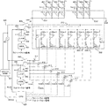
4.ヒータ制御回路の構成
図4は、実施例1のヒータ300の制御回路400の回路図である。401は、画像形成装置100に接続される商用の交流電源である。ヒータ300の電力制御は、トライアック411〜トライアック417の通電/遮断により行われる。トライアック411〜417は、それぞれ、CPU420からのFUSER1〜FUSER7信号に従って動作する。トライアック411〜417の駆動回路は省略して示してある。ヒータ300の制御
回路400は、7つのトライアック411〜417によって、7つの発熱ブロックHB1〜HB7を独立制御可能な回路構成となっている。ゼロクロス検知部421は、交流電源401のゼロクロスを検知する回路であり、CPU420にZEROX信号を出力している。ZEROX信号は、トライアック411〜417の位相制御や波数制御のタイミングの検出等に用いている。
4. Configuration of Heater Control Circuit FIG. 4 is a circuit diagram of the
ヒータ300の温度検知方法について説明する。サーミスタブロックTB1のサ−ミスタT1−1〜T1−4によって検知される温度は、サ−ミスタT1−1〜T1−4と抵抗451〜454との分圧が、Th1−1〜Th1−4信号としてCPU420で検知されている。同様に、サーミスタブロックTB2のサ−ミスタT2−5〜T2−7によって検知される温度は、サ−ミスタT2−5〜T2−7と抵抗465〜467との分圧が、Th2−5〜Th2−7信号としてCPU420で検知されている。CPU420の内部処理では、各発熱ブロックの制御目標温度と、サーミスタの現在の検知温度との差分に基づき、供給するべき電力を算出する。例えばPI制御により供給するべき電力の算出を行う。更に供給する電力に対応した位相角(位相制御)や、波数(波数制御)の制御レベルに換算し、その制御条件によりトライアック411〜417を制御している。
The temperature detection method of the
リレー430、リレー440は、故障などによりヒータ300が過昇温した場合、ヒータ300への電力遮断手段として用いている。リレー430、リレー440の回路動作を説明する。RLON信号がHigh状態になると、トランジスタ433がON状態になり、電源電圧Vccからリレー430の2次側コイルに通電され、リレー430の1次側接点はON状態になる。RLON信号がLow状態になると、トランジスタ433がOFF状態になり、電源電圧Vccからリレー430の2次側コイルに流れる電流は遮断され、リレー430の1次側接点はOFF状態になる。同様に、RLON信号がHigh状態になると、トランジスタ443がON状態になり、電源電圧Vccからリレー440の2次側コイルに通電され、リレー440の1次側接点はON状態になる。RLON信号がLow状態になると、トランジスタ443がOFF状態になり、電源電圧Vccからリレー440の2次側コイルに流れる電流は遮断され、リレー440の1次側接点はOFF状態になる。なお、抵抗434、抵抗444は電流制限抵抗である。
The
リレー430、リレー440を用いた安全回路の動作について説明する。サーミスタTh1−1〜Th1−4による検知温度の何れか1つが、それぞれ設定された所定値を超えた場合、比較部431はラッチ部432を動作させ、ラッチ部432はRLOFF1信号をLow状態でラッチする。RLOFF1信号がLow状態になると、CPU420がRLON信号をHigh状態にしても、トランジスタ433がOFF状態で保たれるため、リレー430はOFF状態(安全な状態)で保つことができる。尚、ラッチ部432は非ラッチ状態において、RLOFF1信号をオープン状態の出力にしている。同様に、サーミスタTh2−5〜Th2−7による検知温度の何れか1つが、それぞれ設定された所定値を超えた場合、比較部441はラッチ部442を動作させ、ラッチ部442はRLOFF2信号をLow状態でラッチする。RLOFF2信号がLow状態になると、CPU420がRLON信号をHigh状態にしても、トランジスタ443がOFF状態で保たれるため、リレー440はOFF状態(安全な状態)で保つことができる。同様に、ラッチ部442は非ラッチ状態において、RLOFF2信号をオープン状態の出力にしている。
The operation of the safety circuit using the
5.ヒータ制御方法の概要
本実施例の画像形成装置は、ホストコンピュータ等の外部装置(不図示)から送られる画像データ(画像情報)に応じて、ヒータ300の7つの発熱ブロックHB1〜HB7それぞれへの供給電力を最適に制御して、画像部を選択的に加熱する構成である。本例の装置において、発熱ブロックHB1〜HB7それぞれへの供給電力を決定するのは、各発熱ブロックHB1〜HB7に設定する、加熱条件の一つとしての制御目標温度(以下、制御
目標温度TGTと表記する)である。発熱ブロックHB1〜HB7に対応するサ−ミスタT1−1〜T2−7の検知温度が、それぞれの発熱ブロックHB1〜HB7に対して設定される制御目標温度TGTを維持するように、CPU420は各発熱ブロックへ供給する電力を制御する。
5. Outline of the heater control method The image forming apparatus of this embodiment is applied to each of the seven heat generating blocks HB1 to HB7 of the
発熱ブロックHB1〜HB7毎に設定される制御目標温度TGTは、記録材に形成されている画像と各発熱ブロックの蓄熱状態によって決められる。本実施例では、まず、画像データ(画像情報)から、トナー量が多い画像に対してより高い温度で加熱が行われるように、制御目標温度TGTの予定値(以下、予定加熱温度FTと呼ぶ)が決められる。更に、画像位置に対応する部分における定着装置の蓄熱量に応じて、上記予定加熱温度FTを補正し、制御目標温度TGTを決定する。実施例1は、定着装置の加熱履歴や放熱履歴により定着装置の蓄熱量を予測する構成である。 The control target temperature TGT set for each of the heat generation blocks HB1 to HB7 is determined by the image formed on the recording material and the heat storage state of each heat generation block. In this embodiment, first, from the image data (image information), the planned value of the control target temperature TGT (hereinafter referred to as the planned heating temperature FT) is used so that the image having a large amount of toner is heated at a higher temperature. ) Is decided. Further, the planned heating temperature FT is corrected according to the amount of heat stored in the fixing device in the portion corresponding to the image position, and the control target temperature TGT is determined. The first embodiment has a configuration in which the amount of heat stored in the fixing device is predicted from the heating history and heat dissipation history of the fixing device.
図5は、ヒータ300によって加熱可能な7つの加熱領域A1〜A7を示す図であり、LETTERサイズ紙の大きさと対比して表示している。加熱領域A1〜A7は発熱ブロックHB1〜HB7が夫々加熱できる領域を示しており、発熱ブロックHB1により加熱領域A1が加熱され、発熱ブロックHB7により加熱領域A7が加熱される構成となっている。7つの発熱ブロックHB1〜HB7は、各ブロックにおける発熱抵抗体への通電量が個別に制御されることで、それぞれの発熱ブロックの発熱量が個別に制御される。加熱領域A1〜A7の全長は220mmであり、各領域はこれを均等に7分割したものである(L=31.4mm)。
FIG. 5 is a diagram showing seven heating regions A 1 to A 7 that can be heated by the
ここで、7つの加熱領域のうちの一つの加熱領域Ai(i=1〜7)中で、記録材搬送方向の一部のみに画像が形成される場合、画像が存在する領域を画像加熱部PRi(i=1〜7)と表記する。この画像加熱部PRi(i=1〜7)は前述した制御目標温度TGTで加熱が行われる。実施例1では、一つの加熱領域Ai(i=1〜7)に形成される予定の画像が記録材搬送方向において複数存在する場合、記録材搬送方向において複数の画像をすべて含み且つ最小の領域を画像加熱部PRi(i=1〜7)とする。また、一つの加熱領域の中で上記画像加熱部PRi以外の部分は、非画像加熱部PPとし、画像加熱部PRiよりも低い温度で加熱を行う。上記条件における、画像情報に応じたヒータ制御方法、予測蓄熱量に応じたヒータ制御補正方法の詳細を以降で説明する。 Here, in one heating area A i (i = 1~7) of the seven heating zones, when the image is formed only on a part of the recording material conveyance direction, the image heating an area where the image is present It is written as part PR i (i = 1 to 7). The image heating unit PR i (i = 1 to 7) is heated at the control target temperature TGT described above. In Example 1, when the image that will be formed in one heating area A i (i = 1~7) there are a plurality of the recording material conveyance direction, wherein all of the plurality of images in the recording material conveyance direction and a minimum of The region is defined as the image heating unit PR i (i = 1 to 7). Further, in one heating region, the portion other than the image heating unit PR i is designated as the non-image heating unit PP, and heating is performed at a temperature lower than that of the image heating unit PR i. The details of the heater control method according to the image information and the heater control correction method according to the predicted heat storage amount under the above conditions will be described below.
6.画像情報に応じたヒータ制御方法
ビデオコントローラ120がホストコンピュータから画像情報を受け取ると、各加熱領域にどのような画像が形成されるかを判別する。そして、トナー量が多い画像に対してより高い温度で加熱が行われるように、制御目標温度TGTの予定値である予定加熱温度FTが決められる。具体的には、CMYK画像データから得られる各色の画像濃度をトナー量に変換したトナー量換算値に応じて、トナー量換算値が高い画像に対してはより高い温度で加熱を行うように、予定加熱温度FTが決められる。
6. Heater control method according to image information When the
(予定加熱温度の決定方法)
まず、トナー量換算値Dの取得方法について述べる。ホストコンピュータ等の外部装置からの画像データは画像形成装置のビデオコントローラ120で受信され、ビットマップデータへの変換が行われる。なお、本実施例の画像形成装置の画素数は600dpiであり、ビデオコントローラ120はそれに応じたビットマップデータ(CMYK各色の画像濃度データ)を作成する。本実施例の画像形成装置は、ビットマップデータから各ドットについてCMYK各色の画像濃度を取得し、これをトナー量換算値Dに変換する。
(Method of determining the planned heating temperature)
First, a method of acquiring the toner amount conversion value D will be described. Image data from an external device such as a host computer is received by the
図6は、実施例1で、各ページにおいて各加熱領域(例えばAi)内の画像加熱部PRiにおけるトナー量換算値Dの最大値DMAX(i)を取得し、これに応じた予定加熱温
度を決定するフローを示した図である。上記のようにビットマップデータへの変換が完了すると、S601からフローがスタートする。S602で加熱領域Ai内に画像加熱部PRiが存在するか確認し、画像加熱部PRiが無ければ、S610に進み非画像加熱部PPに対する予定加熱温度PTを設定し終了となる。画像加熱部PRiがある場合は、S603で画像加熱部PRi内にある各ドットの画像濃度検知が開始される。CMYK画像データに変換された画像データから、ドット毎のC,M,Y,K各色の画像濃度であるd(C)、d(M)、d(Y)、d(K)が得られる。S604でその合算値であるd(CMYK)を算出する。これを画像加熱部PRi内にある全ドットについて行い、S605で全てのドットに対するd(CMYK)の取得が確認されると、S606でこれらをトナー量換算値Dに変換する。
Figure 6 is planned, in Example 1, to get the maximum value D MAX (i) of the toner amount conversion value D of the image heating unit PR i in the heating areas (e.g. A i) in each page, in accordance with this It is a figure which showed the flow which determines a heating temperature. When the conversion to the bitmap data is completed as described above, the flow starts from S601. In S602, it is confirmed whether the image heating unit PR i exists in the heating region A i , and if there is no image heating unit PR i , the process proceeds to S610, the planned heating temperature PT for the non-image heating unit PP is set, and the process ends. If there is an image heating unit PR i is the image density detection of each dot in the image heating unit PR i is started in S603. From the image data converted into CMYK image data, d (C), d (M), d (Y), and d (K), which are the image densities of each of the C, M, Y, and K colors for each dot, can be obtained. In S604, d (CMYK), which is the total value, is calculated. This is performed for all the dots in the image heating unit PR i , and when the acquisition of d (CMYK) for all the dots is confirmed in S605, these are converted into the toner amount conversion value D in S606.
ここで、ビデオコントローラ120内での画像情報は8ビット信号であり、トナー単色当たりの画像濃度d(C)、d(M)、d(Y)、d(K)は、最小濃度00h〜最大濃度FFhの範囲で表わされる。また、これらの合算値であるd(CMYK)は、2バイトの8ビット信号である。前述のように、S606でこのd(CMYK)値をトナー量換算値D(%)に変換する。具体的には、トナー単色当たりの最小画像濃度00hを0%、最大画像濃度FFhを100%として変換する。このトナー量換算値D(%)は、実際の記録材P上の単位面積当たりのトナー量に対応するものであり、本実施例では記録材上トナー量0.50mg/cm2=100%としている。
Here, the image information in the
そして、S607で画像加熱部PRi内にある全ドットのトナー量換算値D(%)の中から、最大値であるトナー量換算最大値DMAX(i)(%)が抽出される。d(CMYK)は複数のトナー色の合計値であり、トナー量換算最大値DMAX(i)の値は100%を超える場合もある。本実施例の画像形成装置では記録材P上のトナー量を全ベタ画像で1.15mg/cm2(トナー量換算値Dの値で230%相当)が上限となるように調整されている。S607でトナー量換算最大値DMAX(i)が得られると、S608でこのトナー量換算最大値DMAX(i)に対応する加熱温度であるFTi値(詳細は後述)が画像加熱部PRiに対する予定加熱温度として設定される。次に、S609で加熱領域Ai内に非画像加熱部PPが存在するか確認し、非画像加熱部PPが無ければ、そのままフローが終了する。非画像加熱部PPが存在する場合、S610に進み非画像加熱部PPに対する予定加熱温度PTを設定し終了となる。 Then, in S607, the maximum toner amount conversion maximum value D MAX (i) (%), which is the maximum value, is extracted from the toner amount conversion value D (%) of all the dots in the image heating unit PR i. d (CMYK) is the total value of a plurality of toner colors, and the value of the maximum toner amount conversion value D MAX (i) may exceed 100%. In the image forming apparatus of this embodiment, the amount of toner on the recording material P is adjusted so that the upper limit is 1.15 mg / cm 2 (corresponding to 230% in terms of the toner amount conversion value D) for all solid images. When the maximum toner amount conversion value D MAX (i) is obtained in S607, the FT i value (details will be described later), which is the heating temperature corresponding to the maximum toner amount conversion value D MAX (i), is the image heating unit PR. It is set as the planned heating temperature for i. Next, verify the non-image heating unit PP is present in the heating region A i at S609, if there is no non-image heating unit PP, as flow ends. If the non-image heating unit PP is present, the process proceeds to S610, the planned heating temperature PT for the non-image heating unit PP is set, and the process ends.
以上のフローを、加熱領域A1〜A7について行い、それぞれの領域に対し、画像加熱部PRiについてはそれぞれのトナー量換算最大値DMAX(i)に対応する予定加熱温度FTiが設定され、非画像加熱部PPに対しては予定加熱温度PTが設定される。
The above flow is performed for
図7に、本実施例におけるトナー量換算最大値DMAX(i)と予定加熱温度FTiの関係を示す(i=1〜7)。本実施例では、トナー量換算最大値DMAX(i)に応じて予定加熱温度FTiが5段階に可変となっている。トナー量換算最大値DMAX(i)の値が大きく、トナー量が多い画像に対しては、十分にトナーが溶けるように、予定加熱温度FTiとして高い温度が設定される。なお、画像が形成されない非画像加熱部PPに対しては、画像加熱部PRiより低温の予定加熱温度PT(例えば120℃)が設定される。予定加熱温度PTは固定値である。 FIG. 7 shows the relationship between the maximum toner amount conversion value D MAX (i) and the planned heating temperature FT i in this embodiment (i = 1 to 7). In this embodiment, the planned heating temperature FT i is variable in 5 steps according to the maximum toner amount conversion value D MAX (i). For an image having a large toner amount conversion maximum value DMAX (i) and a large amount of toner, a high temperature is set as the planned heating temperature FT i so that the toner is sufficiently melted. A planned heating temperature PT (for example, 120 ° C.) lower than that of the image heating unit PR i is set for the non-image heating unit PP on which an image is not formed. The planned heating temperature PT is a fixed value.
7.予測蓄熱量に応じたヒータ制御補正方法
上述のように、加熱領域A1〜A7、それぞれの領域に対し、画像加熱部PRiについては、それぞれのトナー量換算最大値DMAX(i)に対応する予定加熱温度FTiが設定され、非画像加熱部PPに対しては、予定加熱温度PTが設定される。実施例1の構成は、このようにして決定された予定加熱温度を、各加熱領域の予測蓄熱量に応じて補正し、実際に記録材Pを加熱する際の加熱条件の一つである制御目標温度TGT(詳細は後述
)を決定する。
7. Heater control correction method according to the predicted heat storage amount As described above, for each of the heating regions A 1 to A 7 , the image heating unit PR i is set to the maximum value D MAX (i) in terms of the amount of toner. The corresponding planned heating temperature FT i is set, and the planned heating temperature PT is set for the non-image heating unit PP. The configuration of the first embodiment is a control in which the planned heating temperature thus determined is corrected according to the predicted heat storage amount of each heating region, and is one of the heating conditions when actually heating the recording material P. The target temperature TGT (details will be described later) is determined.
(予測蓄熱量の決定方法)
まず、本実施例では、加熱領域A1〜A7、それぞれの領域に対する熱履歴を表す蓄熱カウンタを設ける。蓄熱カウンタの値をCTとすると、蓄熱カウンタ値CTは、それぞれの加熱領域がどの程度加熱されたか、また、どの程度放熱したか、その加熱履歴、放熱履歴を示すものである(詳細は後述)。そして、上記蓄熱カウンタの値CTを用いて、加熱領域A1〜A7に対する予測蓄熱量としての領域蓄熱量HRVを決定する。
(Method of determining the predicted heat storage amount)
First, in this embodiment, heat storage counters indicating the heat history for each of the heating regions A 1 to A 7 are provided. Assuming that the value of the heat storage counter is CT, the heat storage counter value CT indicates how much each heating region is heated, how much heat is dissipated, the heating history, and the heat dissipation history (details will be described later). .. Then, the region heat storage amount HRV as the predicted heat storage amount for the heating regions A 1 to A 7 is determined by using the value CT of the heat storage counter.
ある一つの加熱領域Aiに対する領域蓄熱量HRViを決定する際には、加熱領域Aiとこれに隣接する加熱領域Ai−1、Ai+1に対する蓄熱カウンタの値CTi、CTi−1、CTi+1が用いられる(詳細は後述)。実施例1では、1ページ毎(そのページのプリントが実行された直後)に、上記予測蓄熱量としての領域蓄熱量HRVを求め、次のページでは、この値に応じて、実際に記録材Pの画像加熱部PRiを加熱する際の温度である制御目標温度TGT(PRi)を決定する。以下に、蓄熱カウンタ値CT、領域蓄熱量HRVについて詳細に説明する。 In determining the area heat storage amount HRV i for a single heating region A i, the heating area A i and heating area A i-1, the value of the heat accumulation counter for A i + 1 CT i adjacent thereto, CT i-1 , CT i + 1 is used (details will be described later). In the first embodiment, the region heat storage amount HRV as the predicted heat storage amount is obtained for each page (immediately after the printing of the page is executed), and on the next page, the recording material P is actually obtained according to this value. The control target temperature TGT (PR i ), which is the temperature at which the heating unit PR i is heated, is determined. The heat storage counter value CT and the region heat storage amount HRV will be described in detail below.
7−1.蓄熱カウンタのカウント方法
各加熱領域の加熱履歴、放熱履歴を示す蓄熱カウンタ値CTの決定方法を説明する。各加熱領域に対する蓄熱カウンタは、その加熱領域に対する加熱動作や、記録材の通紙状況に応じて、規定の方法に従い熱履歴をカウントしていくものである。蓄熱カウンタのカウント値CTは、下記の(式1)で表わされる。
CT=(TC×LC)+(WUC+INC+PC)−(RMC+DC)…(式1)
7-1. Counting method of heat storage counter A method of determining the heat storage counter value CT showing the heating history and heat dissipation history of each heating region will be described. The heat storage counter for each heating region counts the heat history according to a specified method according to the heating operation for the heating region and the paper passing condition of the recording material. The count value CT of the heat storage counter is represented by the following (Equation 1).
CT = (TC x LC) + (WUC + INC + PC)-(RMC + DC) ... (Equation 1)
図8を参照して、(式1)中の加熱履歴としての(TC×LC)、(WUC+INC+PC)、放熱履歴としての(RMC+DC)について説明する。なお、本実施例における蓄熱カウント値CTは1ページ毎(そのページのプリントが実行された直後)に更新されるものとする。
TCは、図8の(a)に示すように、記録材の画像加熱部PRiを加熱する際の制御目標温度TGT(PRi)に応じて決定される値であり、制御目標温度TGT(PRi)が高温であるほど値が大きくなっている。
LCは、図8の(b)に示すように、画像加熱部PRiを加熱する際に加熱を行った距離HL(mm)に応じて決定される値であり、HLが長くなるほど値が大きくなっている。
画像が形成される加熱領域では、画像加熱部PRiとそれ以外の非画像加熱部PPに対する(TC×LC)が加算されて1ページ分になる。
With reference to FIG. 8, (TC × LC), (WUC + INC + PC) as the heating history, and (RMC + DC) as the heat dissipation history in (Equation 1) will be described. The heat storage count value CT in this embodiment shall be updated every page (immediately after printing of that page is executed).
As shown in FIG. 8A, TC is a value determined according to the control target temperature TGT (PR i ) when heating the image heating unit PR i of the recording material, and is a control target temperature TGT ( The higher the temperature of PR i ), the larger the value.
As shown in FIG. 8B, LC is a value determined according to the heating distance HL (mm) when the image heating unit PR i is heated, and the value increases as the HL becomes longer. It has become.
In the heating region where the image is formed, (TC × LC) for the image heating unit PR i and the other non-image heating unit PP is added to obtain one page.
その他のWUC、INC、PCは、図8の(c)に示すように、プリント開始時の立上げ、紙間、プリント終了時の後回転に対してカウントされる固定値である。これらWUC、INC、PCは、例えば、立上げ時間、紙間、後回転時間が動作条件により、変化した場合は、これに応じて変化させることもできる。なお、加熱履歴を表すパラメータとしては上記のものに限定されるものではなく、ヒータの温度履歴や発熱体への供給電力の履歴を示す他のパラメータを用いてもよい。 The other WUC, INC, and PC are fixed values that are counted with respect to the start-up at the start of printing, the space between papers, and the post-rotation at the end of printing, as shown in FIG. 8 (c). These WUCs, INCs, and PCs can be changed according to, for example, the start-up time, the space between papers, and the back rotation time depending on the operating conditions. The parameter representing the heating history is not limited to the above, and other parameters indicating the temperature history of the heater and the history of the power supplied to the heating element may be used.
また、RMC、DCは、図8の(c)に示すように、記録材Pが通紙されることにより像加熱装置から奪われる熱、外気への放熱に対してカウントされる固定値であり、図8の(c)には、LETTERサイズ紙を1枚通紙したときの値を表示している。これらRMC、DCは、記録材の種類や環境条件により、それらに応じた値に変化させることもできる。なお、放熱カウントDCについては、プリント時以外にもカウントされ、規定時間が経過すると、規定の値がカウントされる(例えば、1分間で3つカウントアップ)。また
、放熱履歴を表すパラメータとしては上記のものに限定されるものではなく、その加熱領域における記録材の通過履歴や発熱体への電力供給を行わない期間を示す他のパラメータを用いてもよい。
Further, RMC and DC are fixed values that are counted against the heat taken from the image heating device and the heat radiation to the outside air by passing the recording material P through the paper, as shown in FIG. 8C. , FIG. 8C shows the value when one sheet of LETTER size paper is passed. These RMCs and DCs can be changed to values corresponding to them depending on the type of recording material and environmental conditions. The heat dissipation count DC is counted at times other than printing, and when the specified time elapses, the specified value is counted (for example, three counts up in one minute). Further, the parameter representing the heat dissipation history is not limited to the above, and other parameters indicating the passage history of the recording material in the heating region and the period during which the power is not supplied to the heating element may be used. ..
以上の様に、本実施例における蓄熱カウンタのカウント値CTは、各領域において、それぞれの領域に対する熱履歴情報のみから1ページ毎(そのページのプリントが実行された直後)にカウントされるものである。 As described above, the count value CT of the heat storage counter in this embodiment is counted for each page (immediately after the printing of that page is executed) from only the heat history information for each area in each area. be.
7−2.領域蓄熱量の決定方法
実施例1では、上記の蓄熱カウント値CTから、1ページ毎(そのページのプリントが実行された直後)に、予測蓄熱量としての領域蓄熱量HRVを求める。そして、次のページでは、この値に応じて、実際に記録材Pの画像加熱部PRiを加熱する際の温度である制御目標温度TGT(PRi)を決定する。まず、加熱領域Aiに対する蓄熱カウンタのカウント値をCTiで表わすと、加熱領域Aiに対する領域蓄熱量HRViは、蓄熱カウント値CTi−1、CTi、CTi+1から下記の(式2)により算出される。
HRVi=CTi+α(CTi−1+CTi+1)…(式2)
ここで、αは定数である。
7-2. Method for determining the area heat storage amount In Example 1, the area heat storage amount HRV as the predicted heat storage amount is obtained for each page (immediately after the printing of the page is executed) from the above heat storage count value CT. Then, on the next page, the control target temperature TGT (PR i ), which is the temperature at which the image heating unit PR i of the recording material P is actually heated, is determined according to this value. First, when representing the count value of the heat accumulation counter for heating area A i in CT i, area heat storage amount HRV i to the heating area A i is the heat storage count value CT i-1, CT i, from CT i + 1 of the following (Formula 2 ) Is calculated.
HRV i = CT i + α (CT i-1 + CT i + 1 ) ... (Equation 2)
Here, α is a constant.
(式2)からわかるように、ある一つの加熱領域Aiに対する領域蓄熱量HRViは、当該加熱領域である加熱領域Aiと、その両隣の隣接加熱領域Ai−1、Ai+1の熱履歴から決定される値であり、この値が加熱領域Aiの予測蓄熱量を示す値である。両端の加熱領域であるA1とA7の領域蓄熱量HRViは、当該加熱領域と隣にある一つの加熱領域の熱履歴から決定されることになる。 As can be seen from equation (2), area heat storage amount HRV i for a single heating region A i has a heating area A i is the heating region, adjacent the heating area A i-1 of both adjacent, A i + 1 of the heat is a value determined from the history, the value is a value indicating the predictive heat storage amount of the heating area a i. The area heat storage amount HRV i of A 1 and A 7 which are the heating areas at both ends is determined from the heat history of the heating area and one heating area adjacent to the heating area.
(式2)中の定数αは、隣接する加熱領域の熱履歴の当該加熱領域の予測蓄熱量に対する影響度合いを示す値であり、実施例1の構成ではα=0.2である。このように、本実施例に係る画像形成装置においては、各加熱領域の予測蓄熱量を、当該領域に隣接する加熱領域の熱履歴も考慮して決定することで、予測蓄熱量の予測精度を向上させている。本実施例では、このようにして決定される領域蓄熱量HRViを用い、画像加熱部PRiに対する予定加熱温度FTiを補正することで、より適正な制御目標温度TGT(PRi)が得られる。 The constant α in (Equation 2) is a value indicating the degree of influence of the heat history of the adjacent heating region on the predicted heat storage amount of the heating region, and α = 0.2 in the configuration of Example 1. As described above, in the image forming apparatus according to the present embodiment, the predicted heat storage amount of each heating region is determined in consideration of the heat history of the heating region adjacent to the region, thereby determining the prediction accuracy of the predicted heat storage amount. It is improving. In this embodiment, a more appropriate control target temperature TGT (PR i ) can be obtained by correcting the planned heating temperature FT i for the image heating unit PR i using the region heat storage amount HRV i determined in this way. Be done.
図9に、領域蓄熱量HRViと、予定加熱温度FTiに対する補正値VAの関係を示した。この領域蓄熱量HRViと、予定加熱温度FTiに対する補正値VAの関係は、あらかじめ実施例1の定着装置で、蓄熱状態と定着後の画像特性を確認し、その結果から決定されている。なお、本実施例において、非画像加熱部PPに対しては、領域蓄熱量HRViによる補正は行わない(領域蓄熱量HRViの値に関係なく制御目標温度TGT(PP)=120℃)こととする。 FIG. 9 shows the relationship between the regional heat storage amount HRV i and the correction value VA with respect to the planned heating temperature FT i. The relationship between the heat storage amount HRV i in this region and the correction value VA with respect to the planned heating temperature FT i is determined from the results of confirming the heat storage state and the image characteristics after fixing in advance with the fixing device of Example 1. In the present embodiment, with respect to the non-image heating unit PP, not perform the correction by the area heat storage amount HRV i (area heat storage HRV i control target temperature TGT (PP) = 120 ℃ regardless of the value of) the And.
7−3.制御目標温度の決定方法
図10に、本実施例における、加熱領域Aiの画像加熱部PRi、非画像加熱部PPに対する制御目標温度TGTの決定フローを示す。ここで、現在のページ番号をPNで表わすこととする。フローがスタートすると、まずS1001で前ページまでの領域蓄熱量HRVi[PN−1]が取得される。S1002で加熱領域Aiに画像加熱部PRiが存在するか否かを確認する。画像加熱部PRiが存在する場合は、S1003でその画像加熱部PRiに対し、前述した図6の制御フローにより決定される予定加熱温度FTiを取得する。画像加熱部PRiが存在しない場合は、非画像加熱部PPに対する制御目標温度を決定するためS1006へ進む。
7-3. Method for Determining Control Target Temperature FIG. 10 shows a flow for determining the control target temperature TGT for the image heating unit PR i and the non-image heating unit PP in the heating region A i in this embodiment. Here, the current page number is represented by PN. When the flow starts, first, in S1001, the area heat storage amount HRV i [PN-1] up to the previous page is acquired. In S1002, it is confirmed whether or not the image heating unit PR i exists in the heating region A i. If the image heating unit PR i is present, S1003 acquires the planned heating temperature FT i determined by the control flow of FIG. 6 described above for the image heating unit PR i. If the image heating unit PR i does not exist, the process proceeds to S1006 to determine the control target temperature for the non-image heating unit PP.
S1004では、S1003で得られた画像加熱部PRiに対する予定加熱温度FTi
に対して予測蓄熱量に応じた補正を行う。まず、前述の図9に従い、S1001で得られた前ページまでの領域蓄熱量HRVi[PN−1]に応じ、予定加熱温度FTiに対する補正値VA(HRVi[PN−1])が選択される。次に、この補正値VA(HRVi[PN−1])を用いて予定加熱温度FTiに対し、下記(式3)を用いて補正を行い、画像加熱部PRiに対する制御目標温度TGT(PRi)が決定される。
TGT(PRi)=FTi+VA(HRVi[PN−1])…(式3)
In S1004, the planned heating temperature FT i for the image heating unit PR i obtained in S1003
Is corrected according to the predicted heat storage amount. First, according to FIG. 9 described above, the correction value VA (HRV i [PN-1]) for the planned heating temperature FT i is selected according to the region heat storage amount HRV i [PN-1] obtained in S1001 up to the previous page. Will be done. Next, this correction value VA (HRV i [PN-1]) is used to correct the planned heating temperature FT i using the following (Equation 3), and the control target temperature TGT (for the image heating unit PR i) ( PR i ) is determined.
TGT (PR i ) = FT i + VA (HRV i [PN-1]) ... (Equation 3)
以上の様に、S1004で画像加熱部PRiに対する制御目標温度TGT(PRi)が決定されると、S1005で加熱領域Aiに非画像加熱部PPが存在するか否かを確認する。非画像加熱部PPが存在するときは、S1006、S1007において、非画像加熱部PPに対する予定加熱温度PT、制御目標温度TGT(PP)が決定され(TGT(PP)=PT)、S1008へ進む。非画像加熱部PPが存在しない場合は、S1005から直接S1008へ進む。S1008で現ページ(ページ番号=PN)のプリントが、ここまでのフローで決定された制御目標温度TGTを用いて実行される。次にS1009において、現ページまでの領域蓄熱量HRVi[PN]が算出され、S1010でページ番号が次ページのものに更新される。S1011でプリント終了するかを確認し、現ページでプリント終了の場合はここでフローが終了し、プリントが継続される場合は、S1001からのフローを繰り返す。 As described above, the control target temperature TGT for the image heating unit PR i (PR i) is determined in S1004, the non-image heating unit PP to heating area A i in S1005 confirms whether there exists. When the non-image heating unit PP is present, in S1006 and S1007, the planned heating temperature PT and the control target temperature TGT (PP) for the non-image heating unit PP are determined (TGT (PP) = PT), and the process proceeds to S1008. If the non-image heating unit PP does not exist, the process proceeds directly from S1005 to S1008. In S1008, printing of the current page (page number = PN) is executed using the control target temperature TGT determined in the flow up to this point. Next, in S1009, the area heat storage amount HRV i [PN] up to the current page is calculated, and in S1010, the page number is updated to that of the next page. It is confirmed in S1011 whether the printing is completed, and if the printing is completed on the current page, the flow ends here, and if the printing is continued, the flow from S1001 is repeated.
8.比較例との比較
ここからは、本発明により予測蓄熱量の予測精度が向上する様子を、比較例の構成と比較しつつ説明する。以下に示す図11と図13の2種類の画像パターンを用いてプリントを行った場合を例にとり、説明を行う。
8. Comparison with Comparative Example From here, it will be described how the present invention improves the prediction accuracy of the predicted heat storage amount while comparing it with the configuration of the comparative example. A case where printing is performed using the two types of image patterns shown in FIGS. 11 and 13 shown below will be described as an example.
8−1.画像パターンの説明
図11と図13の画像パターンについて説明する。図11にはLETTERサイズ紙に形成される画像P1、P2を示している。これらの画像P1、P2は、シアン(C)、マゼンタ(M)、イエロー(Y)の均一な画像濃度の3次色であり、P1、P2の画像濃度をトナー量換算値D(%)に変換した値は共に、210%であるものとする。加熱領域、A1、A2、A4、A6、A7には画像が形成されないものとする。加熱領域A3、A5における画像加熱部PRiをPR3、PR5とし、その開始部をPRS、終了部をPREで示している。本実施例では、画像加熱部PRiの開始部PRSは、画像先端から5mmだけ記録材の先端側に設定した。また、本実施例における画像加熱部PRiの終了部PREは、画像後端部から5mmだけ記録材の後端側に設定した。
8-1. Description of Image Patterns The image patterns of FIGS. 11 and 13 will be described. FIG. 11 shows images P1 and P2 formed on LETTER size paper. These images P1 and P2 are tertiary colors having uniform image densities of cyan (C), magenta (M), and yellow (Y), and the image densities of P1 and P2 are converted to the toner amount conversion value D (%). It is assumed that both converted values are 210%. It is assumed that no image is formed in the heating regions, A 1 , A 2 , A 4 , A 6 and A 7. The image heating portions PR i in the heating regions A 3 and A 5 are designated as PR 3 and PR 5 , the start portion thereof is indicated by PRS, and the end portion is indicated by PRE. In this embodiment, the start portion PRS of the image heating portion PR i is set to the tip side of the recording material by 5 mm from the tip of the image. Further, the end portion PRE of the image heating portion PR i in this embodiment is set to the rear end side of the recording material by 5 mm from the rear end portion of the image.
ここで、前述したように、実際に記録材Pを加熱する際の温度は制御目標温度TGTと表記される。本実施例では、画像加熱部PRiの開始部PRSまでに、非画像加熱部PPに対する制御目標温度TGT(PP)(例えば予定加熱温度PT=120℃)から、画像加熱部PRiの加熱に用いる制御目標温度TGT(PRi)までヒータ温度を昇温させる。すなわち、画像加熱部PRiの開始部PRSまでに、定着フィルム202の表面温度が画像を定着するために必要な温度に到達するように昇温が開始される。
Here, as described above, the temperature at which the recording material P is actually heated is referred to as the control target temperature TGT. In this embodiment, the control target temperature TGT (PP) for the non-image heating unit PP (for example, the planned heating temperature PT = 120 ° C.) is changed to the heating of the image heating unit PR i by the start portion PRS of the image heating unit PR i . The heater temperature is raised to the control target temperature TGT (PR i) to be used. That is, the temperature rise is started so that the surface temperature of the fixing
実施例1では、図8の(b)に示される、加熱を行った距離HL(mm)は、画像加熱部PRiの記録材搬送方向長さと、上述の昇温に要する距離を足し合わせた距離とした。この、加熱を行った距離HL(mm)に応じて、前述の(式1)におけるLCの値が決まり、蓄熱カウント値CTの算出に用いられる。図11の画像パターンでは、画像加熱部PR3、PR5に対して加熱を行った距離HL(mm)は、LETTERサイズ紙の搬送方向長さと等しい279mmであり、上述の昇温動作が記録材先端から開始されるものとする。また、これ以降の説明で用いる画像に対する加熱距離HL(mm)も、上記と同様に、画像加熱部PRの記録材搬送方向長さと、昇温動作に要する距離を足し合わせた距離と
する。
In Example 1, the heating distance HL (mm) shown in FIG. 8B is the sum of the length of the image heating unit PR i in the recording material transport direction and the distance required for the above-mentioned temperature rise. It was a distance. The LC value in the above-mentioned (Equation 1) is determined according to the heating distance HL (mm), and is used for calculating the heat storage count value CT. In the image pattern of FIG. 11, the distance HL (mm) obtained by heating the image heating units PR 3 and PR 5 is 279 mm, which is equal to the length in the transport direction of the LETTER size paper, and the above-mentioned temperature raising operation is the recording material. It shall start from the tip. Further, the heating distance HL (mm) for the image used in the following description is also the distance obtained by adding the length of the image heating unit PR in the recording material transport direction and the distance required for the temperature raising operation in the same manner as described above.
図12は、図6、図7で説明した方法に従い決定した、図11の画像パターンの各加熱領域A1〜A7における、画像加熱部PRiのトナー量換算最大値DMAXと予定加熱温度FT、非画像加熱部PPの予定加熱温度PTの値である。
12, FIG. 6, was determined in accordance with the method described in FIG. 7, in the
図13は、加熱領域A3に画像P3、加熱領域A4に画像P4が、加熱領域A5に画像P5が形成される画像パターンである。画像P3、P4、P5は共にトナー量換算値D(%)が40%のシアン(C)、マゼンタ(M)、イエロー(Y)の3次色が均一に形成(トナー量換算最大値DMAX(i)(%)=40%)されたものである。加熱領域、A1、A2、A6、A7には画像が形成されないものとする。加熱領域A3、A4、A5における画像加熱部PRiをPR3、PR4、PR5とし、その開始部をPRS、終了部をPREで示している。 Figure 13 is an image P3 in the heating area A 3, the image P4 to the heating area A 4 is an image pattern image P5 is formed in the heating region A 5. In the images P3, P4, and P5, the tertiary colors of cyan (C), magenta (M), and yellow (Y) having a toner amount conversion value D (%) of 40% are uniformly formed (toner amount conversion maximum value D MAX). (I) (%) = 40%). It is assumed that no image is formed in the heating regions, A 1 , A 2 , A 6 and A 7. The image heating portions PR i in the heating regions A 3 , A 4 , and A 5 are designated as PR 3 , PR 4 , and PR 5 , the start portion thereof is indicated by PRS, and the end portion is indicated by PRE.
8−2.比較条件の説明
上記で説明した、図11と図13の2種類の画像パターンを用いて次のようなプリントを行う。まず、LETTERサイズ紙に図11の画像パターンを30枚連続してプリントする。その直後、LETTERサイズ紙に図13の画像パターンを1枚プリントする。このとき、図13の画像パターンをプリントする際、図中の搬送方向位置LHにおいて、各加熱領域に対する制御目標温度TGTにどのような温度が設定されるかを、以降で説明する本発明の実施例1と比較例で比較する。
8-2. Explanation of Comparison Conditions The following printing is performed using the two types of image patterns of FIGS. 11 and 13 described above. First, 30 consecutive image patterns of FIG. 11 are printed on LETTER size paper. Immediately after that, one image pattern of FIG. 13 is printed on LETTER size paper. At this time, when printing the image pattern of FIG. 13, what kind of temperature is set for the control target temperature TGT for each heating region at the transport direction position LH in the drawing will be described below. Comparison is made between Example 1 and Comparative Example.
8−3.実施例1の説明
本実施例は、前述の(式1)、(式2)から得られる領域蓄熱量HRViを用い、図9に従って、画像加熱部PRiに対する予定加熱温度FTiを補正し、制御目標温度TGT(PRi)を決定する。前述のように、図9には領域蓄熱量HRViと、予定加熱温度FTiに対する補正値VAの関係を示されている。
8-3. The present embodiment of Example 1, the above-described (Equation 1), using the area heat storage amount HRV i obtained from equation (2), according to FIG. 9, to correct the scheduled heating temperature FT i for the image heating unit PR i , Control target temperature TGT (PR i ) is determined. As described above, FIG. 9 shows the relationship between the region heat storage amount HRV i and the correction value VA with respect to the planned heating temperature FT i.
まず、図11の画像パターンでLETTERサイズ紙を連続プリントしたときの、各加熱領域A1〜A7における実施例1の領域蓄熱量HRViを確認する。
図15(a)に、図11の画像パターンを連続してプリントしたときの、実施例1における領域蓄熱量HRViの推移を示す。図15(a)におけるLM1〜LM5は、図9に示した、領域蓄熱量HRViと制御目標温度TGT(PRi)に対する補正値VAの関係において、補正値VAが変化する領域蓄熱量HRVの値を示している。具体的には、LM1、LM2、LM3、LM4、LM5の値は、順に20、50、100、150、200である。
First, when the LETTER size paper were continuously printed with the image pattern of Figure 11, to check the space heat storage amount HRV i of Example 1 in the
FIG. 15A shows the transition of the regional heat storage amount HRV i in Example 1 when the image pattern of FIG. 11 is continuously printed. LM1 to LM5 in FIG. 15A show the region heat storage amount HRV in which the correction value VA changes in the relationship between the region heat storage amount HRV i and the correction value VA with respect to the control target temperature TGT (PR i) shown in FIG. Shows the value. Specifically, the values of LM1, LM2, LM3, LM4, and LM5 are 20, 50, 100, 150, and 200, respectively.
図15(a)に示すように、実施例1における領域蓄熱量HRViの推移は4種類に分かれる。まず、最も領域蓄熱量HRViの増加速度が速いのは、画像が形成される加熱領域A3、A5であり、次に増加速度が速いのは、画像が形成される加熱領域に挟まれた加熱領域A4である。次に領域蓄熱量HRViの増加速度が速いのは、片側のみが画像が形成される加熱領域に接する加熱領域A2、A6であり、最も増加速度が遅いのは両端に位置する加熱領域A1、A7である。30枚プリント直後の領域蓄熱量の値は、HRV3とHRV5は223.8、HRV4は152.1、HRV2とHRV6は128.2、HRV1とHRV7は89.4である。 As shown in FIG. 15A, the transition of the regional heat storage amount HRV i in Example 1 is divided into four types. First, the increase rate of most areas the quantity of thermal storage HRV i fast, a heating area A 3, A 5 on which an image is formed, the next increase speed is high, flanked by heating region on which the image is formed It was a heating area a 4. Then the faster the rate of increase of area heat storage HRV i is the heating area A 2, A 6 in contact with the heating region only one side image is formed, the heating region increased most rate located slow both ends A 1 and A 7 . The values of the area heat storage amount immediately after printing 30 sheets are 223.8 for HRV 3 and HRV 5 , 152.1 for HRV 4 , 128.2 for HRV 2 and HRV 6 , and 89.4 for HRV 1 and HRV 7. ..
図16を用いて、図11の画像パターンでLETTERサイズ紙を30枚プリントした直後に、図13の画像パターンをプリントするときに、図中の搬送方向位置LHにおいて設定される制御目標温度TGTについて説明する。図16には、図13の画像パターンにおける各加熱領域での、画像加熱部PRiに対するトナー量換算最大値DMAX(i)、
これに対応する予定加熱温度FTi、また、非画像加熱部PPに対する予定加熱温度PTが示されている。これらの値を基に、実施例1と、後述する比較例1−1、比較例1−2のそれぞれの構成において決定される制御目標温度が示されている。
About the control target temperature TGT set at the transport direction position LH in the drawing when printing the image pattern of FIG. 13 immediately after printing 30 sheets of LETTER size paper with the image pattern of FIG. 11 using FIG. explain. In FIG. 16, the maximum toner amount conversion value D MAX (i) for the image heating unit PR i in each heating region in the image pattern of FIG. 13 is shown.
The corresponding planned heating temperature FT i and the planned heating temperature PT for the non-image heating portion PP are shown. Based on these values, the control target temperature determined in each configuration of Example 1, Comparative Example 1-1 and Comparative Example 1-2 described later is shown.
これまで説明したように、実施例1では、直前の図11の画像パターン30枚プリントによる各加熱領域の予測蓄熱量として領域蓄熱量HRViが算出され、前述の(式3)から制御目標温度TGT(PRi)が決められる。実施例1では、TGT(PR3)、TGT(PR4)、TGT(PR5)の値は、185、187、185℃となる。 As described above, in the first embodiment, the region heat storage amount HRV i is calculated as the predicted heat storage amount of each heating region by printing 30 image patterns of FIG. 11 immediately before, and the control target temperature is calculated from the above (Equation 3). TGT (PR i ) is decided. In Example 1, the values of TGT (PR 3 ), TGT (PR 4 ), and TGT (PR 5 ) are 185, 187, and 185 ° C.
8−4.比較例1−1の説明
比較例1−1は、各加熱領域の蓄熱量による補正を行わず、予定加熱温度FTiをそのまま、各加熱領域の画像加熱部PRiにおける制御目標温度TGT(PRi)とする構成である。比較例1−1では蓄熱量による補正は行われないため、制御目標温度TGT(PRi)は予定加熱温度FTiがそのまま用いられる。従って、図16に示すように、比較例1−1では、TGT(PR3)、TGT(PR4)、TGT(PR5)の値は、193、193、193℃となる。
8-4. Explanation of Comparative Example 1-1 In Comparative Example 1-1, the planned heating temperature FT i is not corrected by the amount of heat storage in each heating region, and the control target temperature TGT (PR) in the image heating unit PR i of each heating region is used as it is. i ). Since the correction by the amount of heat storage is not performed in Comparative Example 1-1, the planned heating temperature FT i is used as it is as the control target temperature TGT (PR i). Therefore, as shown in FIG. 16, in Comparative Example 1-1, the values of TGT (PR 3 ), TGT (PR 4 ), and TGT (PR 5 ) are 193, 193, and 193 ° C.
8−5.比較例1−2の説明
比較例1−2は、各加熱領域の予測蓄熱量は、当該加熱領域の熱履歴のみから決定し、この予測蓄熱量から、画像加熱部PRiに対する予定加熱温度FTiを補正し、制御目標温度TGT(PRi)を決定する構成である。すなわち、蓄熱カウンタのカウント値CTiをそのまま予測蓄熱量として用いる比較の構成である。
8-5. Explanation of Comparative Example 1-2 In Comparative Example 1-2, the predicted heat storage amount of each heating region is determined only from the heat history of the heating region, and from this predicted heat storage amount, the planned heating temperature FT for the image heating unit PR i The configuration is such that i is corrected and the control target temperature TGT (PR i ) is determined. That is, it is a comparative configuration in which the count value CT i of the heat storage counter is used as it is as the predicted heat storage amount.
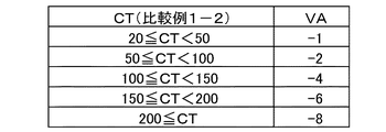
図14に比較例1−2における蓄熱カウンタのカウント値CTiと、予定加熱温度FTiに対する補正値VAの関係を示す。図15(b)に、図11の画像パターンを連続してプリントしたときの、比較例1−2における蓄熱カウント値CTiの推移を示す。画像が形成される加熱領域A3、A5と、画像が形成されない加熱領域A1、A2、A4、A6、A7では蓄熱カウント値CTiの推移が異なり、画像が形成される加熱領域の方が蓄熱カウント値CTiの増加速度が速い。30枚プリント直後の蓄熱カウント値は、CT3とCT5は195.8、CT1、CT2、CT4、CT6、CT7は74.5である。
FIG. 14 shows the relationship between the count value CT i of the heat storage counter in Comparative Example 1-2 and the correction value VA with respect to the planned heating temperature FT i. FIG. 15B shows the transition of the heat storage count value CT i in Comparative Example 1-2 when the image pattern of FIG. 11 is continuously printed. The
比較例1−2では、直前の30枚プリントによる各加熱領域の予測蓄熱量として蓄熱カウント値CTiが算出され、前述の図14から得られる補正値VAを用いて、下記の(式4)より制御目標温度TGT(PRi)が決められる。
TGT(PRi)=FTi+VA(CTi[PN−1])…(式4)
In Comparative Example 1-2, the heat storage count value CT i is calculated as the predicted heat storage amount of each heating region by the immediately preceding 30-sheet print, and the following (Equation 4) is used by using the correction value VA obtained from FIG. The control target temperature TGT (PR i ) is further determined.
TGT (PR i ) = FT i + VA (CT i [PN-1]) ... (Equation 4)
図16に示すように、比較例1−2では、TGT(PR3)、TGT(PR4)、TGT(PR5)の値は、187、191、187℃となる。 As shown in FIG. 16, in Comparative Example 1-2, the values of TGT (PR 3 ), TGT (PR 4 ), and TGT (PR 5 ) are 187, 191 and 187 ° C.
8−6.実施例と比較例の比較
以上のように、同じプリント履歴、同じプリント条件であるのも関わらず、構成によって画像加熱部PRiに対する制御目標温度が異なることになる。実施例1では、隣接する加熱領域の熱履歴の影響を考慮した蓄熱量予測を行っているため、比較例より精度良く実際の蓄熱量に近い値を予測できる。このため、図13の画像加熱領域に対する制御目標温度TGT(PR3)、TGT(PR4)、TGT(PR5)の値は、比較例より低温に設定される。
8-6. Comparison of Examples and Comparative Examples As described above, although the print history and the print conditions are the same, the control target temperature for the image heating unit PR i differs depending on the configuration. In Example 1, since the heat storage amount is predicted in consideration of the influence of the heat history of the adjacent heating region, a value closer to the actual heat storage amount can be predicted with higher accuracy than in the comparative example. Therefore, the values of the control target temperatures TGT (PR 3 ), TGT (PR 4 ), and TGT (PR 5 ) with respect to the image heating region in FIG. 13 are set to be lower than those in the comparative example.
実施例1よりも制御目標温度が高温に設定されている比較例1−1、比較例1−2では、本来必要な熱量より多く、画像加熱領域に対して過剰な熱供給が行われることになる。この結果、蓄熱量を全く考慮しない比較例1−1では、過加熱により画像P3、P4、P
5のトナーが定着フィルム202の表面に付着し、回転1周後にこれが記録材へ付着する、所謂ホットオフセットが発生してしまった。また、当該加熱領域の熱履歴だけを考慮して制御目標温度を決定する比較例1−2では、上記のようなホットオフセットは発生しないものの、制御目標温度TGT(PR3)、TGT(PR4)、TGT(PR5)が実施例1に対して高温に設定される。したがって、その高温設定の分だけ、本来不要な電力が消費されることになり、省電力性が低下する。
In Comparative Example 1-1 and Comparative Example 1-2 in which the control target temperature is set to a higher temperature than in Example 1, the amount of heat originally required is larger than the amount of heat originally required, and excessive heat is supplied to the image heating region. Become. As a result, in Comparative Example 1-1 in which the amount of heat storage is not considered at all, the images P3, P4, P are due to overheating.
The toner of No. 5 adhered to the surface of the fixing
以上のように、画像情報に応じて長手方向に複数設けられた発熱ブロックの加熱条件を調整する画像形成装置において、実施例1では精度良く各加熱領域の蓄熱量を予測することができる。これにより省電力性を向上させつつ、良好な出力画像を得ることが可能となった。 As described above, in the image forming apparatus for adjusting the heating conditions of a plurality of heat generating blocks provided in the longitudinal direction according to the image information, in the first embodiment, the amount of heat stored in each heating region can be predicted with high accuracy. This makes it possible to obtain a good output image while improving power saving.
上記実施例では、加熱条件として制御目標温度を予測蓄熱量に応じて設定したが、加熱条件として、例えば、ヒータへ供給する供給電力を各加熱領域の予測蓄熱量に応じて調整しても良い。また、例えば、加熱条件として加熱開始タイミングを予測蓄熱量に応じて可変とし、予測蓄熱量が少ないときは、加熱開始タイミングを早めることで、定着装置をより暖めるようにしても良い。また、本実施例の説明では、蓄熱量を予想する際に参照する熱履歴として、前のプリント時の制御目標温度を用いたが、ヒータへ供給した供給電力を参照し、この電力量に応じて蓄熱量を予測することもできる。また、本実施例では、予測蓄熱量としての領域蓄熱量HRVの取得(更新)を1ページ毎、すなわち1つの記録材が像加熱部を通過するごとに行ったが、更新の頻度は所定ページ毎(規定枚数通過する毎)としてもよい。 In the above embodiment, the control target temperature is set as the heating condition according to the predicted heat storage amount, but as the heating condition, for example, the supply power supplied to the heater may be adjusted according to the predicted heat storage amount in each heating region. .. Further, for example, as a heating condition, the heating start timing may be made variable according to the predicted heat storage amount, and when the predicted heat storage amount is small, the heating start timing may be advanced to further warm the fixing device. Further, in the description of this embodiment, the control target temperature at the time of the previous printing was used as the heat history to be referred to when predicting the amount of heat storage, but the power supplied to the heater is referred to and the amount of power is adjusted. It is also possible to predict the amount of heat storage. Further, in this embodiment, the region heat storage amount HRV as the predicted heat storage amount is acquired (updated) page by page, that is, every time one recording material passes through the image heating unit, but the frequency of update is a predetermined page. It may be every time (every time the specified number of sheets is passed).
なお、説明を分かりやすくするため、実施例1では、非画像加熱部PPに対して、領域蓄熱量HRViによる補正は行わない(領域蓄熱量HRViの値に関係なく制御目標温度TGT(PP)=120℃)構成を用いて説明を行った。しかしながら、非画像加熱部PPに対しても領域蓄熱量HRViによる補正を実施し、更なる省電力化を図ることもできる。 In order to simplify the description, in the first embodiment, with respect to the non-image heating unit PP, area heat storage HRV i correction by is not performed (a region heat storage amount HRV i values in relation without control target temperature TGT the (PP ) = 120 ° C.) The description was given using the configuration. However, the non-image heating portion PP can also be corrected by the regional heat storage amount HRV i to further reduce power consumption.
[実施例2]
本発明の実施例2では、加熱領域Ai内に複数の画像加熱部PRが設定され、個々の画像加熱部PRに対して最適な制御目標温度TGTが設定される構成とした。このすることで、実施例1で用いた構成より更に省電力性を向上させることが可能となる。なお、実施例2における、画像形成装置、定着装置(像加熱装置)、ヒータ、ヒータ制御回路の構成は、実施例1と同様のため、説明を省略する。実施例2においてここで特に説明しない事項は実施例1と同様である。
[Example 2]
In Example 2 of the present invention, it is set a plurality of image heating section PR in the heating area A i, optimal control target temperature TGT is configured to be set for each image heating portion PR. By doing so, it is possible to further improve the power saving property as compared with the configuration used in the first embodiment. Since the configurations of the image forming device, the fixing device (image heating device), the heater, and the heater control circuit in the second embodiment are the same as those in the first embodiment, the description thereof will be omitted. Matters not particularly described here in the second embodiment are the same as those in the first embodiment.
9.複数の画像加熱部PRに対する制御目標温度の決定方法
図17に示す画像パターンを用いて説明する。図17にはLETTERサイズ紙に形成される画像P6〜P11が示されている。これらの画像P6〜P11は、シアン(C)、マゼンタ(M)、イエロー(Y)の均一な画像濃度の3次色である。P6〜P8の画像濃度をトナー量換算値D(%)に変換した値は210%であり、P9〜P11の画像濃度をトナー量換算値D(%)に変換した値は40%である。それぞれの画像P6〜P11に対して設定される画像加熱部は、PR3−1、PR4−1、PR5−1、及び、PR3−2、PR4−2、PR5−2となる。上記全ての画像加熱部の搬送方向長さは65mmであり、画像加熱部PR3−2、PR4−2、PR5−2の開始部PRS3−2、4−2、5−2は記録材の先端PLEから175mm下流に位置する。本実施例では、例えば、加熱領域A4において、PR4−1とPR4−2に対して別々の制御目標温度が設定される。このとき、それぞれ画像加熱部の直前までの、加熱領域A4の予測蓄熱量を参照し、この予測蓄熱量によって、実施例1と同様の補正が行われる。
9. Method for determining control target temperature for a plurality of image heating units PR This will be described using the image pattern shown in FIG. FIG. 17 shows images P6 to P11 formed on LETTER size paper. These images P6 to P11 are tertiary colors having a uniform image density of cyan (C), magenta (M), and yellow (Y). The value obtained by converting the image densities of P6 to P8 into the toner amount converted value D (%) is 210%, and the value obtained by converting the image densities of P9 to P11 into the toner amount converted value D (%) is 40%. The image heating units set for the respective images P6 to P11 are PR 3-1 and PR 4-1 and PR 5-1 and PR 3-2 , PR 4-2 and PR 5-2. .. The length of all the image heating units in the transport direction is 65 mm, and the image heating units PR 3-2 , PR 4-2 , and PR 5-2 start portions PRS 3-2, 4-2, and 5-2 are recording materials. It is located 175 mm downstream from the tip PLE. In this embodiment, for example, in the heating area A 4, separate control target temperature with respect to PR 4-1 and PR 4-2 is set. At this time, just before each image heating unit, with reference to the predicted heat storage amount of the heating area A 4, this prediction heat storage amount, the same correction as in Example 1 are carried out.
9−1.蓄熱カウント値、領域蓄熱量の更新方法
実施例2では、領域蓄熱量HRViの値の更新を規定間隔で実施し、それぞれの画像加熱部PRが始まる直前までの領域蓄熱量HRViに応じ、画像加熱部PRに対する制御目標温度TGT(PR)を決定する。すなわち、本実施例では、予測蓄熱量としての領域蓄熱量HRViの値が、一枚の記録材が定着部を通過する間に複数回更新される。
9-1. Method for updating the regional heat storage count value and the regional heat storage amount In Example 2, the regional heat storage amount HRV i values are updated at specified intervals, and the regional heat storage amount HRV i is updated according to the region heat storage amount HRV i until immediately before the start of each image heating unit PR. The control target temperature TGT (PR) for the image heating unit PR is determined. That is, in this embodiment, the value of the region heat storage amount HRV i as the predicted heat storage amount is updated a plurality of times while one recording material passes through the fixing portion.
ここで、本実施例では、領域蓄熱量HRViの更新間隔は記録材の搬送距離で5.58mmとしており、これ以降この長さを更新間隔LFと呼ぶことにする。上記更新間隔LFをより短い距離に設定するほど、より実際の蓄熱量に近い領域蓄熱量HRViの値が得られる。但し、必要以上に短い距離に設定すると、以降で説明する領域蓄熱量HRVや蓄熱カウント値CTの算出を頻繁に実行せねばならず、この算出を行う、例えば、制御部113の演算部(不図示)の負荷が必要以上に増加するため好ましくない。よって、実施例2では、上記弊害を避けつつ、必要十分な精度の領域蓄熱量HRVを得ることが可能な更新間隔LFとして、LETTERサイズ紙の搬送方向長さの1/50相当の距離である5.58mmを採用した。なお、更新間隔LFは、装置の構成やプリント速度等に応じて、最適な値を用いることができる。 Here, in this embodiment, the update interval of the region heat storage amount HRV i is 5.58 mm in terms of the transport distance of the recording material, and this length will be referred to as the update interval LF thereafter. The shorter the update interval LF is set, the more the value of the region heat storage amount HRV i closer to the actual heat storage amount can be obtained. However, if the distance is set shorter than necessary, the area heat storage amount HRV and the heat storage count value CT, which will be described later, must be calculated frequently. The load (shown in the figure) increases more than necessary, which is not preferable. Therefore, in the second embodiment, the update interval LF capable of obtaining the region heat storage amount HRV with necessary and sufficient accuracy while avoiding the above-mentioned adverse effects is a distance equivalent to 1/50 of the length in the transport direction of the LETTER size paper. 5.58 mm was adopted. An optimum value can be used for the update interval LF according to the configuration of the apparatus, the printing speed, and the like.
本実施例では、更新間隔LFの間隔で領域蓄熱量HRViの更新を順次実行し、それぞれの画像加熱部PRが始まる直前までの領域蓄熱量HRViに応じ、画像加熱部PRに対する制御目標温度TGT(PR)を決定する。画像形成装置の電源がオンされ、領域蓄熱量HRViの更新が開始されてからの更新回数をnとする。更新回数nは電源オン時にリセットされ、その後更新間隔LFの間隔でカウントアップされる。 In this embodiment, the region heat storage amount HRV i is sequentially updated at the update interval LF, and the control target temperature for the image heating unit PR is determined according to the region heat storage amount HRV i until immediately before the start of each image heating unit PR. Determine TGT (PR). Let n be the number of updates since the power of the image forming apparatus is turned on and the update of the area heat storage amount HRV i is started. The update count n is reset when the power is turned on, and then counted up at the update interval LF.
9−2.領域蓄熱量の決定方法
実施例2では、加熱領域Aiにおける、領域蓄熱量をHRVi[n]、蓄熱カウント値を、CTi[n]とする。電源オン時における領域蓄熱量の初期値はHRVi[0]、蓄熱カウントの初期値はCTi[0]となる。実施例1と同様に、加熱領域Aiにおける領域蓄熱量HRVi[n]は、加熱領域Ai、Ai−1、Ai+1における蓄熱カウント値CTi[n]、CTi−1[n]、CTi+1[n]を用い、以下に示す(式5)により決定される。
HRVi[n]=CTi[n]+α(CTi−1[n]+CTi+1[n])…(式5)
なお、αは定数であり、実施例2においても実施例1と同じく、α=0.2である。
9-2. In decision process Example 2 regions heat storage amount, in the heating region A i, HRV i [n] the area heat storage capacity, the heat storage count value, and CT i [n]. The initial value of the area heat storage amount when the power is turned on is HRV i [0] , and the initial value of the heat storage count is CT i [0] . As in Example 1, area heat storage amount in the heating area A i HRV i [n] is the heating region A i, A i-1, A i + 1 in the heat storage count value CT i [n], CT i -1 [n ] , CT i + 1 [n] is used, and it is determined by the following (Equation 5).
HRV i [n] = CT i [n] + α (CT i-1 [n] + CT i + 1 [n] ) ... (Equation 5)
Note that α is a constant, and in Example 2 as in Example 1, α = 0.2.
9−3.蓄熱カウンタのカウント方法
次に、本実施例における、蓄熱カウント値CTi[n]について詳細に説明する。本例の蓄熱カウント値CTi[n]を算出する際に用いるパラメータは、基本的には実施例1における(式1)と同様である。しかしながら、これらパラメータの値は、前述の更新間隔LFで更新された値が用いられる。実施例2における蓄熱カウント値CTi[n]は、以下の(式6)で表わされる。
CTi[n]=CTi[n−1]+(TC×LC)i[n]+(WUC+INC+PC)i[n]−(RMC+DC)i[n]…(式6)
但し、CTi[0]=CTINT
9-3. Counting Method of Heat Storage Counter Next, the heat storage count value CT i [n] in this embodiment will be described in detail. The parameters used when calculating the heat storage count value CT i [n] of this example are basically the same as those of (Equation 1) in Example 1. However, as the values of these parameters, the values updated at the above-mentioned update interval LF are used. The heat storage count value CT i [n] in Example 2 is represented by the following (Equation 6).
CT i [n] = CT i [n-1] + (TC × LC) i [n] + (WUC + INC + PC) i [n] − (RMC + DC) i [n] … (Equation 6)
However, CT i [0] = CT INT
図18を参照して、(式6)中のTC、LC、RMC、DC、また、WUC、INC、PC、について説明する。(式6)のTCは、図18の(a)に示すように、記録材Pを加熱する際の制御目標温度TGTに応じて決定される値であり、制御目標温度TGTが高温であるほど値が大きくなっている。なお、図18の(a)は、実施例1における図8の(a)と全く同じ内容である。(式6)のLCは、図18の(b)に示すように、記録材
Pを加熱する際に加熱を行った距離HL(mm)に応じて決定される値であり、HLが長くなるほど値が大きくなっている。実施例2では、更新間隔LFにおいて用いられた制御目標温度TGTと、加熱を行った距離HL(mm)に応じて、(式6)の(TC×LC)i[n]項を求める。このため、図18の(b)におけるHLは、更新間隔LF(5.58mm)に対応した値の範囲に対して設定されている。なお、(TC×LC)i[n]項は、更新間隔LF内で制御目標温度TGTが変化した場合、それぞれの制御目標温度TGTと加熱を行った距離に対応するTC×LCを、更新間隔LF分加算することで値が得られる。
With reference to FIG. 18, TC, LC, RMC, DC, and WUC, INC, PC in (Equation 6) will be described. As shown in FIG. 18A, the TC of (Equation 6) is a value determined according to the control target temperature TGT when heating the recording material P, and the higher the control target temperature TGT, the higher the temperature. The value is increasing. Note that FIG. 18A has exactly the same contents as FIG. 8A in Example 1. As shown in FIG. 18B, the LC of (Equation 6) is a value determined according to the distance HL (mm) that was heated when the recording material P was heated, and the longer the HL, the more. The value is increasing. In the second embodiment, the (TC × LC) i [n] term of (Equation 6) is obtained according to the control target temperature TGT used in the update interval LF and the heating distance HL (mm). Therefore, the HL in FIG. 18B is set with respect to the range of values corresponding to the update interval LF (5.58 mm). In the (TC × LC) i [n] term, when the control target temperature TGT changes within the update interval LF, the TC × LC corresponding to each control target temperature TGT and the heating distance is updated at the update interval. A value can be obtained by adding LF.
WUC、INC、PCは、図18の(c)に示すように、プリント開始時の立上げ、紙間、プリント終了時の後回転に対してカウントされる値であり、図18の(c)に示した値は更新間隔LF分の値である。なお、実施例2では、通常動作時におけるプリント開始時の立上げ、紙間、プリント終了時の後回転に要する時間は、それぞれ更新間隔LFの180回、10回、180回分である。(式6)の(WUC+INC+PC)i[n]項は、プリント開始時の立上げ、紙間、プリント終了時の後回転時において、更新間隔LF毎に、それぞれの動作に対応した図18の(c)の値を用いて値が得られる。 As shown in (c) of FIG. 18, WUC, INC, and PC are values that are counted with respect to the start-up at the start of printing, the space between papers, and the post-rotation at the end of printing, and (c) in FIG. The value shown in is the value for the update interval LF. In the second embodiment, the time required for the start-up at the start of printing, the space between papers, and the post-rotation at the end of printing in the normal operation is 180 times, 10 times, and 180 times of the update interval LF, respectively. The (WUC + INC + PC) i [n] term of (Equation 6) corresponds to each operation at each update interval LF at the time of start-up at the start of printing, between papers, and at the time of post-rotation at the end of printing. A value is obtained using the value of c).
また、(式6)のRMC、DCは、記録材Pが通紙されることにより像加熱装置から奪われる熱、外気への放熱に対してカウントされる固定値であり、図18の(d)に示した値は更新間隔LF分の値である。これらRMC、DCは、実施例1同様、記録材の種類や環境条件により、それらに応じた値に変化させることもできる。(式6)の(RMC+DC)i[PN,n]項は、更新間隔LF毎に図18の(d)の値を用いて値が得られる。また、実施例2の放熱カウントDCは、実施例1と同じく、プリント時以外にもカウントされ、規定時間が経過すると、規定の値がカウントされる(例えば、1分間で3だけカウントアップ)。 Further, the RMC and DC of (Equation 6) are fixed values that are counted against the heat taken from the image heating device and the heat radiation to the outside air by passing the recording material P through the paper, and are the fixed values (d) in FIG. ) Is the value for the update interval LF. Similar to Example 1, these RMCs and DCs can be changed to values corresponding to them depending on the type of recording material and the environmental conditions. The (RMC + DC) i [PN, n] term of (Equation 6) is obtained by using the value of (d) of FIG. 18 for each update interval LF. Further, the heat dissipation count DC of the second embodiment is counted other than at the time of printing as in the first embodiment, and when the specified time elapses, the specified value is counted (for example, the count is increased by 3 in one minute).
電源オン時における領域蓄熱量の初期値はHRVi[0]、蓄熱カウントの初期値はCTi[0]となる。ここで、n=0における蓄熱カウント値CTi[0]は、電源オン時や、一般的な画像形成装置において用いられる省電力待機モード(以降では、スリープモードと呼ぶ)からの復帰時における初期値である。蓄熱カウント値CTi[0]の値は、前回の電源オフ時や、スリープモードへの移行時に記憶しておいた蓄熱カウントの最終値CTi[n]を基に得られる値を用いても良い。また、電源オン時や、スリープモードからの復帰時における、像加熱装置に備えられたサーミスタ等温度検知手段の検知温度に応じた値を用いることもできる。このようにして得られる電源オン時や、スリープモードからの復帰時における蓄熱カウント値を、蓄熱カウント初期値CTINTとする。蓄熱カウントが開始される際の蓄熱カウント値CTi[0]は、上記の蓄熱カウント初期値CTINTにセットされる。 The initial value of the area heat storage amount when the power is turned on is HRV i [0] , and the initial value of the heat storage count is CT i [0] . Here, the heat storage count value CT i [0] at n = 0 is the initial stage when the power is turned on or when returning from the power saving standby mode (hereinafter referred to as sleep mode) used in a general image forming apparatus. The value. The value of the heat storage count value CT i [0] can be obtained by using the value obtained based on the final value CT i [n] of the heat storage count stored at the time of the previous power off or the transition to the sleep mode. good. Further, it is also possible to use a value corresponding to the detection temperature of a temperature detecting means such as a thermistor provided in the image heating device when the power is turned on or when returning from the sleep mode. The heat storage count value obtained in this way when the power is turned on or when returning from the sleep mode is defined as the heat storage count initial value CT INT . The heat storage count value CT i [0] when the heat storage count is started is set to the above-mentioned initial heat storage count value CT INT.
9−4.蓄熱カウント値、領域蓄熱量の更新フロー
図19に、実施例2において、電源オン、またはスリープモードから復帰した直後にプリント開始し、再度スリープモードへ移行するまでの加熱領域Aiの蓄熱カウント値CTi[n]、領域蓄熱量HRVi[n]の算出フローを示す。まず、S1901で、前述した蓄熱カウントの初期値CTINTが取得される。S1902でn=0とされ、S1903でCTi[0]には初期値CTINTの値がセットされる。S1904でプリントが開始される。
9-4. Heat storage count value, the update flow diagram 19 of a region the heat storage amount, in Example 2, the power-on or print starts immediately after returning from the sleep mode, the heat storage count value of the heating area A i up moves again to the sleep mode, The calculation flow of CT i [n] and region heat storage amount HRV i [n] is shown. First, in S1901, the above-mentioned initial value CT INT of the heat storage count is acquired. In S1902, n = 0, and in S1903, the initial value CT INT value is set in CT i [0]. Printing starts at S1904.
S1905で、定着フィルム202及び加圧ローラ208の搬送距離が更新間隔LFだけ進むと、S1906でnの値がインクリメントされた上で、S1907において蓄熱カウントの更新値CTi[n]が算出される。本実施例では、上記と同じフローで隣接する加熱領域Ai−1と、加熱領域Ai+1の蓄熱カウント値CTi−1[n]、CTi+1
[n]が算出されている。S1908では、上記の値を用いて、前述の(式5)で示した領域蓄熱量HRVi[n]が算出される。その後、S1909でプリントが継続されるか否かを確認し、プリントが継続される場合は、S1905からのフローを繰り返す。S1909でプリント終了が確認されると、S1910でプリントの終了となる。
In S1905, when the transport distance between the fixing
[N] has been calculated. In S1908, the region heat storage amount HRV i [n] represented by the above-mentioned (Equation 5) is calculated using the above values. After that, it is confirmed in S1909 whether or not printing is continued, and if printing is continued, the flow from S1905 is repeated. When the end of printing is confirmed in S1909, the end of printing is completed in S1910.
プリント終了後は、前述したように、S1911で、規定時間が経過するとnの値がインクリメントされ、放熱カウントDCが規定の値だけカウントアップ(例えば、1分間で3だけカウントアップ)する。そして、これに連動して蓄熱カウント値CTi[n]と領域蓄熱量HRVi[n]が更新される。S1912で次のプリント命令があるかどうかを確認し、次のプリント命令が来ていれば、S1904からのフローを繰り返す。 After the printing is completed, as described above, in S1911, the value of n is incremented when the specified time elapses, and the heat dissipation count DC counts up by the specified value (for example, counts up by 3 in 1 minute). Then, in conjunction with this, the heat storage count value CT i [n] and the region heat storage amount HRV i [n] are updated. It is confirmed in S1912 whether or not there is a next print instruction, and if the next print instruction comes, the flow from S1904 is repeated.
次のプリントが来ていなければS1913でスリープモードへ移行するかどうかを確認する。実施例2では、プリントが終了してから、あらかじめ決められた規定の経過時間(例えば5分)の間に、次のプリント命令が来なければスリープモードへ移行する。S1913では、前回のプリントが終了してから上記規定の経過時間に達したか否かを確認し、規定の経過時間に達していれば、S1914でスリープに入り、フローの終了となる。規定の経過時間に達していなければ、S1913からS1911へ戻り、フローを継続する。なお、スリープ中にプリント命令を受信すると、スリープモードから復帰し、図19の初めからフローが開始される。 If the next print does not come, check whether to shift to the sleep mode in S1913. In the second embodiment, if the next print command does not come within a predetermined elapsed time (for example, 5 minutes) after the printing is completed, the sleep mode is entered. In S1913, it is confirmed whether or not the elapsed time specified above has been reached since the end of the previous print, and if the elapsed time has reached the specified time, sleep is entered in S1914 and the flow ends. If the specified elapsed time has not been reached, the process returns from S1913 to S1911 and the flow is continued. When a print command is received during sleep, the sleep mode is resumed and the flow is started from the beginning of FIG.
以上のようにして、蓄熱カウント値CTi[n]、領域蓄熱量HRVi[n]が、プリント時には更新間隔LF毎に、プリント時以外は規定の時間毎に得られる。 As described above, the heat storage count value CT i [n] and the area heat storage amount HRV i [n] are obtained every update interval LF at the time of printing and at every specified time except at the time of printing.
9−5.制御目標温度の決定方法
本実施例では、各画像加熱部PRそれぞれに対し、その画像加熱部PRが存在するページが定着装置200へ到達する前に、実施例1と同様の方法で予定加熱温度FTが事前に決定される。そして、各画像加熱部PRに対する予定加熱温度FTが、各画像加熱部PRの開始部PRSの直前の領域蓄熱量HRVを用いて補正され、画像加熱部PRに対する制御目標温度TGTとされる。また、加熱領域Aiにおいて、開始部PRSが、更新回数nからn+1の区間内に相当する位置にある画像加熱部PRをPRi[n]と表示する。
9-5. Method for determining control target temperature In this embodiment, for each image heating unit PR, the planned heating temperature is determined by the same method as in Example 1 before the page on which the image heating unit PR exists reaches the fixing
実施例2では、上記の画像加熱部PRi[n]に対する制御目標温度TGT(PRi[n])については次のように決定する。すなわち、加熱開始から、定着フィルム202の表面温度が画像を定着するために必要な温度に到達する昇温時間等を考慮して、更新間隔LFの10倍に相当する搬送距離分前における領域蓄熱量HRVi[n−10]を用いる。本実施例では上記のように更新間隔LFの10倍に相当する搬送距離分前における領域蓄熱量HRVi[n−10]を用いたが、使用する像加熱装置の熱容量や、ヒータへの供給電力により、画像加熱部からどの程度前の領域蓄熱量を用いるかを選択すれば良い。
In the second embodiment, the control target temperature TGT (PR i [n] ) for the image heating unit PR i [n] is determined as follows. That is, in consideration of the temperature rise time at which the surface temperature of the fixing
本実施例の画像形成装置では、加熱領域Aiのどこに画像加熱部PRがあり、その開始部PRSの位置が、上記で述べたどの更新回数区間に存在するかが事前に把握されている。従って、加熱領域Ai内のあるそれぞれの画像加熱部PRに対する制御目標温度TGT(PR)を決定する際、どの更新回数における領域蓄熱量HRVを用いるかも事前に決まっている。よって、画像加熱部PRに対する制御目標温度TGT(PR)の補正に使用される領域蓄熱量HRVが得られたら、この値が用いて制御目標温度TGT(PR)を決定し、画像加熱部PRi[n]に対する加熱のための昇温動作が開始される。 In the image forming apparatus of this embodiment, there is where the image heating portion PR of the heating area A i, the position of the beginning PRS is either present in any number of updates interval described above is known in advance. Therefore, when determining a control target temperature TGT (PR) for heating area A i each image heating portion PR with the, are determined in advance may use area heat storage amount HRV in which the number of updates. Therefore, once the region heat storage amount HRV used for correcting the control target temperature TGT (PR) for the image heating unit PR is obtained, this value is used to determine the control target temperature TGT (PR), and the image heating unit PR i The temperature raising operation for heating with respect to [n] is started.
上記のように、本実施例では画像加熱部PRi[n]に対する制御目標温度TGT(PRi[n])を決定する場合、領域蓄熱量HRVi[n−10]が用いられる。ここで、実施例1と同様の方法で、画像加熱部PRi[n]に対し、予め決定される予定加熱温度
FTをFTi[n]と表示する。画像加熱部PRi[n]に対する制御目標温度TGT(PRi[n])は、予定加熱温度FTi[n]を、領域蓄熱量HRVi[n−10]を用いて補正することで得られることになる。この際の、補正のかけ方は実施例1と同じく、図9に示した領域蓄熱量HRVと補正値VAの関係に従って行われ、下記の(式7)で表わされる。
TGT(PRi[n])=FTi[n]+VA(HRVi[n−10])…(式7)
As described above, in this embodiment, when the control target temperature TGT (PR i [n] ) for the image heating unit PR i [n] is determined, the region heat storage amount HRV i [n-10] is used. Here, in the same manner as in Example 1, the predetermined heating temperature FT is displayed as FT i [n] on the image heating unit PR i [n]. The control target temperature TGT (PR i [n] ) for the image heating unit PR i [n] is obtained by correcting the planned heating temperature FT i [n] using the region heat storage amount HRV i [n-10]. Will be. At this time, the method of applying the correction is the same as in the first embodiment, according to the relationship between the region heat storage amount HRV and the correction value VA shown in FIG. 9, and is represented by the following (Equation 7).
TGT (PR i [n] ) = FT i [n] + VA (HRV i [n-10] ) ... (Equation 7)
なお、実施例1と同じく、本実施例でも非画像加熱部PPに対して、領域蓄熱量HRVによる補正は行わない(領域蓄熱量HRVの値に関係なく制御目標温度TGT(PP)=120℃)こととする。 As in Example 1, in this example as well, the non-image heating unit PP is not corrected by the regional heat storage amount HRV (control target temperature TGT (PP) = 120 ° C. regardless of the value of the regional heat storage amount HRV). )
10.実施例1との比較
ここで、図11の画像パターンでLETTERサイズ紙を29枚プリントした直後に、図17の画像パターンをプリントするときに、図中の搬送方向位置LH2において設定される制御目標温度TGTについて、実施例2と実施例1を比較する。
図20に、図17のLH2部における、各加熱領域での、画像加熱部PRiに対するトナー量換算最大値DMAX(i)、これに対応する予定加熱温度FTi、また、非画像加熱部PPに対する予定加熱温度PTを示している。また、図20には、LH2部における制御目標温度TGT(PRi)及びTGT(PP)、それらを決定する際に用いた領域蓄熱量HRViを示している。実施例2及び実施例1の画像加熱部PRiに対する制御目標温度TGT(PRi)は、領域蓄熱量HRViによる補正により決められるが、以下の違いがある。
10. Comparison with Example 1 Here, when printing the image pattern of FIG. 17 immediately after printing 29 sheets of LETTER size paper with the image pattern of FIG. 11, the control target set at the transport direction position LH2 in the figure is set. Example 2 and Example 1 are compared with respect to the temperature TGT.
In FIG. 20, in the LH2 portion of FIG. 17, the maximum toner amount conversion value DMAX (i) with respect to the image heating portion PR i in each heating region, the corresponding planned heating temperature FT i , and the non-image heating portion are shown. The planned heating temperature PT for PP is shown. Further, FIG. 20 shows the control target temperatures TGT (PR i ) and TGT (PP) in the LH2 portion, and the region heat storage amount HRV i used when determining them. The control target temperature TGT (PR i ) for the image heating unit PR i of Examples 2 and 1 is determined by the correction by the region heat storage amount HRV i , but there are the following differences.
実施例1では、直前の29枚プリントによる各加熱領域の予測蓄熱量として領域蓄熱量HRVi[29]が算出され、これを用いて前述の(式3)から制御目標温度TGT(PRi)が決められる。したがって、領域蓄熱量HRVi[29]には、現在のページにおける、図17のLH1部の熱履歴は全く含まれない。一方、実施例2では、直前の29枚プリントによる各加熱領域の予測蓄熱量に加え、LH2部の先端PH2が位置する更新回数nの10回前、更新回数n−10までの熱履歴も含めた領域蓄熱量HRVi[n−10]が算出される。そして、これを用いて実施例1同様の方法で制御目標温度TGT(PRi[n])が決められる。 In the first embodiment, the region heat storage amount HRV i [29] is calculated as the predicted heat storage amount of each heating region by printing the immediately preceding 29 sheets, and using this, the control target temperature TGT (PR i ) is calculated from the above (Equation 3). Is decided. Therefore, the regional heat storage amount HRV i [29] does not include the heat history of the LH1 part of FIG. 17 on the current page at all. On the other hand, in the second embodiment, in addition to the predicted heat storage amount of each heating region by the immediately preceding 29-sheet print, the heat history up to 10 times before the update number n where the tip PH2 of the LH2 part is located and up to the update number n-10 is included. The area heat storage amount HRV i [n-10] is calculated. Then, using this, the control target temperature TGT (PR i [n] ) is determined by the same method as in Example 1.
実施例2と実施例1では、現在のページにおける、図17のLH1部における更新回数n−10までの熱履歴分だけ、領域蓄熱量HRViの値に差が生じる。この結果、加熱領域A4の画像P10に対する制御目標温度TGT(PR4−2)が異なる温度に設定されることになる。実施例2では制御目標温度TGT(PR4−2)が187℃に、実施例1では189℃に設定される。従って、制御目標温度が低く抑えられる実施例2は、実施例1の制御を用いた場合よりも更に省電力性を向上させることが可能である。 In the second embodiment and the first embodiment, there is a difference in the value of the regional heat storage amount HRV i by the amount of heat history up to the number of updates n-10 in the LH1 part of FIG. 17 on the current page. As a result, the control target temperature TGT for the image P10 of the heating area A 4 (PR 4-2) is set to different temperatures. In the second embodiment, the control target temperature TGT (PR 4-2 ) is set to 187 ° C., and in the first embodiment, the temperature is set to 189 ° C. Therefore, in the second embodiment in which the control target temperature is suppressed to a low level, it is possible to further improve the power saving property as compared with the case where the control of the first embodiment is used.
以上のように実施例2では、定着ニップ部Nを記録材Pが通過中に、領域蓄熱量HRVi[n]の値を規定間隔で更新し、直近の値を用いて画像加熱部に対する制御目標温度を決定した。これにより、その時点における各加熱領域の予測蓄熱量を、実施例1より更に高精度に算出できるので、より最適な制御目標温度を用いて省電力性を向上させることができた。 As described above, in the second embodiment, while the recording material P is passing through the fixing nip portion N, the value of the region heat storage amount HRV i [n] is updated at predetermined intervals, and the latest value is used to control the image heating portion. The target temperature was determined. As a result, the predicted heat storage amount of each heating region at that time can be calculated with higher accuracy than in Example 1, so that power saving can be improved by using a more optimum control target temperature.
本実施例においても、実施例1と同様、加熱条件を、制御目標温度ではなく、電力等にしてもよい。 In this embodiment as well, as in the first embodiment, the heating condition may be electric power or the like instead of the control target temperature.
なお、説明を分かりやすくするため、実施例2も実施例1と同じく、非画像加熱部PPに対して、領域蓄熱量HRViによる補正は行わない(領域蓄熱量HRViの値に関係な
く制御目標温度TGT(PP)=120℃)構成を用いて説明を行った。しかしながら、非画像加熱部PPに対しても領域蓄熱量HRViによる補正を実施し、更なる省電力化を図ることもできる。
また、実施例1、2共に画像情報と熱履歴を用いて加熱条件を設定しているが、熱履歴のみを用いて加熱条件を設定してもよい。即ち、複数の発熱体の夫々を制御する際の加熱条件を、一つの発熱体が加熱する加熱領域の熱履歴と、一つの発熱体に隣接する発熱体が加熱する加熱領域の熱履歴と、に応じて設定してもよい。
In order to simplify the description, the second embodiment as well as
Further, although the heating conditions are set using the image information and the heat history in both Examples 1 and 2, the heating conditions may be set using only the heat history. That is, the heating conditions for controlling each of the plurality of heating elements are the heat history of the heating region heated by one heating element, the heat history of the heating region heated by the heating element adjacent to one heating element, and the heat history of the heating region. It may be set according to.
300…ヒータ、305…基板、301(301a、301b)…導電体、303(303−1〜303−7)…導電体、302(302a−1〜302a−7、302b−1〜302b−7)…発熱抵抗体、400…制御回路、200…像加熱装置、202…定着フィルム 300 ... Heater, 305 ... Substrate, 301 (301a, 301b) ... Conductor, 303 (303-1 to 303-7) ... Conductor, 302 (302a-1 to 302a-7, 302b-1 to 302b-7) ... heating resistor, 400 ... control circuit, 200 ... image heating device, 202 ... fixing film
Claims (15)
前記第1回転体の外周面に接触する第2回転体であって、前記第1回転体との間にニップ部を形成する第2回転体と、
記録材の搬送方向及び記録材の厚み方向の両方向に対して直交する方向に複数の発熱ブロックが並んだヒータと、
前記複数の発熱ブロック毎の加熱条件を発熱ブロック毎に設定する制御部であって、第1の記録材上の画像部を加熱するときの前記発熱ブロックの加熱条件と、第1の記録材上の非画像部を加熱するときの前記発熱ブロックの加熱条件が異なるように設定する制御部と、を有し、
前記ヒータは、前記第1回転体の内部空間に配置されており、
前記ニップ部を記録材が通過することにより、記録材に形成された画像が加熱される像加熱装置であって、
前記ニップ部の領域のうち、前記複数の発熱ブロックのなかの第1発熱ブロックにより加熱される前記第1回転体の領域に対応する前記ニップ部の領域を第1加熱領域、前記ニップ部の領域のうち、前記複数の発熱ブロックのなかの前記第1発熱ブロックに隣接する第2発熱ブロックにより加熱される前記第1回転体の領域に対応する前記ニップ部の領域を第2加熱領域とすると、
前記制御部は、前記第1の記録材上の画像部のうち、前記第1加熱領域により加熱される第1の画像部の先端から後端までの距離に応じて、前記第1加熱領域における第1の蓄熱量を算出し、前記第1の記録材上の画像部のうち、前記第2加熱領域により加熱される第2の画像部の先端から後端までの距離に応じて、前記第2加熱領域における第2の蓄熱量を算出し、
前記第1の記録材の後に第2の記録材が前記ニップ部に搬送される場合、前記第1発熱ブロックの前記加熱条件を、前記第1の蓄熱量及び前記第2の蓄熱量に応じて設定することを特徴とする像加熱装置。 The first rotating body and
A second rotating body that comes into contact with the outer peripheral surface of the first rotating body and that forms a nip portion between the first rotating body and the second rotating body.
A heater in which a plurality of heat generating blocks are arranged in a direction orthogonal to both the transport direction of the recording material and the thickness direction of the recording material.
A control unit that sets the heating conditions for each of the plurality of heat generation blocks for each heat generation block, and the heating conditions for the heat generation block when heating the image unit on the first recording material and the heating conditions on the first recording material. It has a control unit that sets the heating conditions of the heat generating block to be different when heating the non-image part of the above.
The heater is arranged in the internal space of the first rotating body.
An image heating device that heats an image formed on a recording material by passing the recording material through the nip portion.
Among the regions of the nip portion, the region of the nip portion corresponding to the region of the first rotating body heated by the first heat generation block among the plurality of heat generation blocks is the first heating region and the region of the nip portion. Among the plurality of heat generation blocks, the region of the nip portion corresponding to the region of the first rotating body heated by the second heat generation block adjacent to the first heat generation block is defined as the second heating region.
Wherein, the first of the image portion on the recording material, according to the distance in the previous end or et after Tanma the first image portion to be heated by said first heating zone, the first calculating a first quantity of thermal storage in the heating region, the distance in the first of the image portion on the recording material, a second image of the previous edge if et after Tanma heated by the second heating region The second heat storage amount in the second heating region is calculated according to the above.
When the second recording material is conveyed to the nip portion after the first recording material, the heating conditions of the first heat generation block are set according to the first heat storage amount and the second heat storage amount. An image heating device characterized by being set.
前記第1の記録材上の画像部のうち前記第2加熱領域により加熱される画像が複数ある場合、前記第2の画像部は、最初の画像が前記第2加熱領域に到達してから最後の画像が前記第2加熱領域を通過するまでに前記第2加熱領域によって加熱される領域であることを特徴とする請求項1に記載の像加熱装置。 When there are a plurality of images heated by the first heating region among the image portions on the first recording material, the first image portion is the last after the first image reaches the first heating region. Is the region heated by the first heating region before the image of is passed through the first heating region.
When there are a plurality of images heated by the second heating region among the image portions on the first recording material, the second image portion is the last after the first image reaches the second heating region. The image heating device according to claim 1, wherein the image is a region heated by the second heating region before passing through the second heating region.
前記第2の蓄熱量は、前記第2加熱領域が、前記第2加熱領域に対応する前記第2発熱ブロックにより加熱されることに関する情報である加熱履歴、及び、前記第2加熱領域が放熱することに関する情報である放熱履歴によって前記制御部により算出されることを特徴とする請求項1乃至6のいずれか一項に記載の像加熱装置。 The first heat storage amount is a heating history that is information about the first heating region being heated by the first heat generation block corresponding to the first heating region, and the first heating region dissipates heat. Calculated by the control unit based on the heat dissipation history, which is information about the matter.
The second heat storage amount is a heating history that is information about the second heating region being heated by the second heat generation block corresponding to the second heating region, and the second heating region dissipates heat. The image heating device according to any one of claims 1 to 6, wherein the control unit calculates the heat radiation history, which is information about the above.
前記第2加熱領域の前記加熱履歴は、前記第2発熱ブロックの制御目標温度及び、前記第2発熱ブロックに供給する電力、のうち少なくとも1つに応じて、前記制御部により算出されることを特徴とする請求項7に記載の像加熱装置。 The heating history of the first heating region is calculated by the control unit according to at least one of the control target temperature of the first heat generation block and the electric power supplied to the first heat generation block.
The heating history of the second heating region is calculated by the control unit according to at least one of the control target temperature of the second heat generation block and the electric power supplied to the second heat generation block. The image heating device according to claim 7.
てから通過するまでの間に、前記制御部により複数回更新されることを特徴とする請求項1乃至11のいずれか一項に記載の像加熱装置。 The first heat storage amount and the second heat storage amount are characterized in that they are updated a plurality of times by the control unit between the time when the first recording material reaches the nip portion and the time when the first recording material passes through the nip portion. The image heating device according to any one of claims 1 to 11.
記録材に形成された画像を記録材に定着する定着部と、を有する画像形成装置において、
前記定着部が請求項1乃至請求項14のいずれか一項に記載の像加熱装置であることを特徴とする画像形成装置。
An image forming part that forms an image on the recording material,
In an image forming apparatus having a fixing portion for fixing an image formed on a recording material to the recording material.
An image forming apparatus according to any one of claims 1 to 14, wherein the fixing portion is an image heating apparatus.
Priority Applications (6)
| Application Number | Priority Date | Filing Date | Title |
|---|---|---|---|
| JP2016131620A JP6914622B2 (en) | 2016-07-01 | 2016-07-01 | Image forming device and image heating device |
| US15/631,394 US10054882B2 (en) | 2016-07-01 | 2017-06-23 | Image forming apparatus and image heating apparatus |
| US16/052,925 US10338505B2 (en) | 2016-07-01 | 2018-08-02 | Image forming apparatus and image heating apparatus for controlling a heat generating quantity of a plurality of heating elements |
| US16/415,801 US10901349B2 (en) | 2016-07-01 | 2019-05-17 | Image forming apparatus and image heating apparatus for controlling a heat generating quantity of a plurality of heating elements |
| US17/128,596 US11448986B2 (en) | 2016-07-01 | 2020-12-21 | Image forming apparatus and image heating apparatus |
| US17/885,788 US20220382189A1 (en) | 2016-07-01 | 2022-08-11 | Image forming apparatus and image heating apparatus |
Applications Claiming Priority (1)
| Application Number | Priority Date | Filing Date | Title |
|---|---|---|---|
| JP2016131620A JP6914622B2 (en) | 2016-07-01 | 2016-07-01 | Image forming device and image heating device |
Publications (3)
| Publication Number | Publication Date |
|---|---|
| JP2018004943A JP2018004943A (en) | 2018-01-11 |
| JP2018004943A5 JP2018004943A5 (en) | 2019-11-21 |
| JP6914622B2 true JP6914622B2 (en) | 2021-08-04 |
Family
ID=60947890
Family Applications (1)
| Application Number | Title | Priority Date | Filing Date |
|---|---|---|---|
| JP2016131620A Active JP6914622B2 (en) | 2016-07-01 | 2016-07-01 | Image forming device and image heating device |
Country Status (1)
| Country | Link |
|---|---|
| JP (1) | JP6914622B2 (en) |
Families Citing this family (5)
| Publication number | Priority date | Publication date | Assignee | Title |
|---|---|---|---|---|
| US10054882B2 (en) | 2016-07-01 | 2018-08-21 | Canon Kabushiki Kaisha | Image forming apparatus and image heating apparatus |
| JP7129211B2 (en) | 2018-05-18 | 2022-09-01 | キヤノン株式会社 | image forming device |
| JP7206821B2 (en) * | 2018-11-02 | 2023-01-18 | 京セラドキュメントソリューションズ株式会社 | Fixing device and image forming apparatus provided with the fixing device |
| US11392064B2 (en) | 2019-03-27 | 2022-07-19 | Canon Kabushiki Kaisha | Image forming apparatus capable of increasing gloss level of toner image without increasing number of processes performed by fixing unit |
| JP7277233B2 (en) * | 2019-04-16 | 2023-05-18 | キヤノン株式会社 | Image heating device and image forming device |
Family Cites Families (4)
| Publication number | Priority date | Publication date | Assignee | Title |
|---|---|---|---|---|
| TW201325925A (en) * | 2011-12-21 | 2013-07-01 | Cal Comp Electronics & Comm Co | Media storage device and sectional image printing method |
| JP6047855B2 (en) * | 2013-02-07 | 2016-12-21 | 株式会社リコー | Fixing apparatus and image forming apparatus |
| JP2015125165A (en) * | 2013-12-25 | 2015-07-06 | 株式会社リコー | Image forming apparatus and fixing apparatus |
| JP2015176010A (en) * | 2014-03-17 | 2015-10-05 | 株式会社リコー | Fixing control device, fixing control method, and image forming apparatus |
-
2016
- 2016-07-01 JP JP2016131620A patent/JP6914622B2/en active Active
Also Published As
| Publication number | Publication date |
|---|---|
| JP2018004943A (en) | 2018-01-11 |
Similar Documents
| Publication | Publication Date | Title |
|---|---|---|
| US11448986B2 (en) | Image forming apparatus and image heating apparatus | |
| US10488793B2 (en) | Image heating apparatus and image forming apparatus for controlling a temperature of a first heating element and a second heating element | |
| JP6818574B2 (en) | Fixing device and image forming device | |
| US10599077B2 (en) | Image forming apparatus and image heating apparatus that control heating amounts of a region in which an image is formed and a region in which an image is not formed | |
| JP6914622B2 (en) | Image forming device and image heating device | |
| US10838328B2 (en) | Image forming apparatus that controls a setting used for temperature control based on thermal history information | |
| JP7163147B2 (en) | IMAGE HEATING APPARATUS, IMAGE FORMING APPARATUS, AND IMAGE HEATING APPARATUS CONTROL METHOD | |
| US11016425B2 (en) | Image heating device and image forming apparatus | |
| JP2019191245A (en) | Image heating device and image formation apparatus | |
| JP2021131415A (en) | Image heating device, image forming apparatus, and heater | |
| JP7277230B2 (en) | image heating device | |
| JP7009608B2 (en) | Fixing device and image forming device | |
| JP2021162672A (en) | Image forming apparatus | |
| JP2020181053A (en) | Image heating device, and image forming device |
Legal Events
| Date | Code | Title | Description |
|---|---|---|---|
| RD02 | Notification of acceptance of power of attorney |
Free format text: JAPANESE INTERMEDIATE CODE: A7422 Effective date: 20181116 |
|
| A621 | Written request for application examination |
Free format text: JAPANESE INTERMEDIATE CODE: A621 Effective date: 20190628 |
|
| A521 | Written amendment |
Free format text: JAPANESE INTERMEDIATE CODE: A523 Effective date: 20191009 |
|
| A977 | Report on retrieval |
Free format text: JAPANESE INTERMEDIATE CODE: A971007 Effective date: 20200423 |
|
| A131 | Notification of reasons for refusal |
Free format text: JAPANESE INTERMEDIATE CODE: A131 Effective date: 20200526 |
|
| A521 | Written amendment |
Free format text: JAPANESE INTERMEDIATE CODE: A523 Effective date: 20200727 |
|
| A131 | Notification of reasons for refusal |
Free format text: JAPANESE INTERMEDIATE CODE: A131 Effective date: 20201222 |
|
| A521 | Written amendment |
Free format text: JAPANESE INTERMEDIATE CODE: A523 Effective date: 20210219 |
|
| TRDD | Decision of grant or rejection written | ||
| A01 | Written decision to grant a patent or to grant a registration (utility model) |
Free format text: JAPANESE INTERMEDIATE CODE: A01 Effective date: 20210615 |
|
| A61 | First payment of annual fees (during grant procedure) |
Free format text: JAPANESE INTERMEDIATE CODE: A61 Effective date: 20210714 |
|
| R151 | Written notification of patent or utility model registration |
Ref document number: 6914622 Country of ref document: JP Free format text: JAPANESE INTERMEDIATE CODE: R151 |