JP6913673B2 - Microwave ablation device - Google Patents
Microwave ablation device Download PDFInfo
- Publication number
- JP6913673B2 JP6913673B2 JP2018516609A JP2018516609A JP6913673B2 JP 6913673 B2 JP6913673 B2 JP 6913673B2 JP 2018516609 A JP2018516609 A JP 2018516609A JP 2018516609 A JP2018516609 A JP 2018516609A JP 6913673 B2 JP6913673 B2 JP 6913673B2
- Authority
- JP
- Japan
- Prior art keywords
- microwave
- supply line
- radiator
- microwave ablation
- outer sheath
- Prior art date
- Legal status (The legal status is an assumption and is not a legal conclusion. Google has not performed a legal analysis and makes no representation as to the accuracy of the status listed.)
- Active
Links
Images


Classifications
-
- A—HUMAN NECESSITIES
- A61—MEDICAL OR VETERINARY SCIENCE; HYGIENE
- A61B—DIAGNOSIS; SURGERY; IDENTIFICATION
- A61B18/00—Surgical instruments, devices or methods for transferring non-mechanical forms of energy to or from the body
- A61B18/18—Surgical instruments, devices or methods for transferring non-mechanical forms of energy to or from the body by applying electromagnetic radiation, e.g. microwaves
- A61B18/1815—Surgical instruments, devices or methods for transferring non-mechanical forms of energy to or from the body by applying electromagnetic radiation, e.g. microwaves using microwaves
-
- A—HUMAN NECESSITIES
- A61—MEDICAL OR VETERINARY SCIENCE; HYGIENE
- A61B—DIAGNOSIS; SURGERY; IDENTIFICATION
- A61B18/00—Surgical instruments, devices or methods for transferring non-mechanical forms of energy to or from the body
- A61B2018/00005—Cooling or heating of the probe or tissue immediately surrounding the probe
- A61B2018/00011—Cooling or heating of the probe or tissue immediately surrounding the probe with fluids
- A61B2018/00029—Cooling or heating of the probe or tissue immediately surrounding the probe with fluids open
-
- A—HUMAN NECESSITIES
- A61—MEDICAL OR VETERINARY SCIENCE; HYGIENE
- A61B—DIAGNOSIS; SURGERY; IDENTIFICATION
- A61B18/00—Surgical instruments, devices or methods for transferring non-mechanical forms of energy to or from the body
- A61B2018/00053—Mechanical features of the instrument of device
- A61B2018/00273—Anchoring means for temporary attachment of a device to tissue
-
- A—HUMAN NECESSITIES
- A61—MEDICAL OR VETERINARY SCIENCE; HYGIENE
- A61B—DIAGNOSIS; SURGERY; IDENTIFICATION
- A61B18/00—Surgical instruments, devices or methods for transferring non-mechanical forms of energy to or from the body
- A61B2018/00315—Surgical instruments, devices or methods for transferring non-mechanical forms of energy to or from the body for treatment of particular body parts
- A61B2018/00345—Vascular system
-
- A—HUMAN NECESSITIES
- A61—MEDICAL OR VETERINARY SCIENCE; HYGIENE
- A61B—DIAGNOSIS; SURGERY; IDENTIFICATION
- A61B18/00—Surgical instruments, devices or methods for transferring non-mechanical forms of energy to or from the body
- A61B2018/00315—Surgical instruments, devices or methods for transferring non-mechanical forms of energy to or from the body for treatment of particular body parts
- A61B2018/00505—Urinary tract
- A61B2018/00511—Kidney
-
- A—HUMAN NECESSITIES
- A61—MEDICAL OR VETERINARY SCIENCE; HYGIENE
- A61B—DIAGNOSIS; SURGERY; IDENTIFICATION
- A61B18/00—Surgical instruments, devices or methods for transferring non-mechanical forms of energy to or from the body
- A61B2018/00571—Surgical instruments, devices or methods for transferring non-mechanical forms of energy to or from the body for achieving a particular surgical effect
- A61B2018/00577—Ablation
-
- A—HUMAN NECESSITIES
- A61—MEDICAL OR VETERINARY SCIENCE; HYGIENE
- A61B—DIAGNOSIS; SURGERY; IDENTIFICATION
- A61B18/00—Surgical instruments, devices or methods for transferring non-mechanical forms of energy to or from the body
- A61B18/18—Surgical instruments, devices or methods for transferring non-mechanical forms of energy to or from the body by applying electromagnetic radiation, e.g. microwaves
- A61B18/1815—Surgical instruments, devices or methods for transferring non-mechanical forms of energy to or from the body by applying electromagnetic radiation, e.g. microwaves using microwaves
- A61B2018/1861—Surgical instruments, devices or methods for transferring non-mechanical forms of energy to or from the body by applying electromagnetic radiation, e.g. microwaves using microwaves with an instrument inserted into a body lumen or cavity, e.g. a catheter
Description
本発明は、マイクロ波アブレーション装置およびかかる装置を使用する方法に関する。本発明は、血管内交感神経切除術または腎動脈除神経術などの除神経術の分野での応用を見出し得る。本発明はまた、心房および心室の不整脈の治療を含む医療用アブレーションの他の分野における応用も見出し得る。 The present invention relates to a microwave ablation device and a method of using such a device. The present invention may find application in the field of denervation such as intravascular sympathectomy or renal artery denervation. The present invention may also find applications in other areas of medical ablation, including the treatment of atrial and ventricular arrhythmias.
高血圧症は、脳卒中、心臓発作、および腎不全などの終末器官損傷による罹患および死亡の原因となる重大な医学的病状である。多くの患者が、血圧管理のための複数の薬物適用を必要とし、一部の患者については、薬物適用は、耐性が低いか、または全く効果がない。腎動脈除神経術は、医学的療法に対する不応性または不耐性があるこれらの患者において高血圧症を管理するための可能性のある治療選択肢として登場した。本施術は、遠心性神経および求心性神経が血圧を上昇させる神経ホルモン反応の必須成分を形成するため、神経メッセージを腎臓と中枢神経系との間で中継する遠心性神経および求心性神経を除去することを目指している。遠心性神経および求心性神経は、腎動脈および腎周囲脂肪の外側の層(すなわち、外膜)において、主に腎動脈の内側(すなわち、内腔)表面から1〜6mmを移動し、血管内カテーテルアブレーションによって潜在的に破壊される場合がある。 Hypertension is a serious medical condition that causes morbidity and death from terminal organ damage such as stroke, heart attack, and renal failure. Many patients require multiple drug applications for blood pressure control, and for some patients, drug applications are less tolerant or have no effect. Renal artery denervation has emerged as a potential treatment option for managing hypertension in these patients who are refractory or intolerant to medical therapy. This procedure removes the efferent and afferent nerves that relay nerve messages between the kidneys and the central nervous system because the efferent and afferent nerves form the essential components of the neurohormonal response that raises blood pressure. I am aiming to do it. Efferent and afferent nerves travel 1 to 6 mm from the inner (ie, lumen) surface of the renal arteries, primarily in the outer layers of renal arteries and perirenal fat (ie, the adventitia), and are intravascular. Can be potentially destroyed by catheter ablation.
腎動脈除神経術のための高周波カテーテルアブレーションによる初期の臨床試験では、血圧低下という有望な結果を示した。これらの結果により、この応用に関する高周波アブレーションカテーテルの種々の医療団および研究機関による興味および開発が促進された。 Early clinical trials with radiofrequency catheter ablation for renal artery denervation showed promising results in lowering blood pressure. These results facilitated the interest and development of high frequency ablation catheters for this application by various medical teams and research institutes.
腎動脈除神経術のより最近の臨床試験では、Medtronic社によって開発された腎除神経術システムで行われた施術と偽手術対照(operation sham control)との比較が行われ、これは、血圧低下において有意な利益を示すことはできなかった。残念な結果を考慮して専門家によって提示された1つの仮設は、効果のない腎動脈除神経術がこの臨床試験中に発生したということである。 A more recent clinical trial of renal artery denervation compared the procedure performed with the renal denervation system developed by Medtronic with an operation sham control, which reduces blood pressure. Could not show any significant benefit in. One hypothesis presented by experts in light of the disappointing results is that ineffective renal artery denervation occurred during this clinical trial.
腎動脈除神経術用に使用される先行技術の高周波カテーテルは、腎神経に影響が及ぶ前に腎動脈の全厚が損傷するという欠点を有し得る。この理由により、動脈の控えめなアブレーションが典型的には行われ、それによって腎動脈狭窄を回避する。しかしながら、このタイプの控えめなアブレーションは、このエネルギー源による腎神経の徐神経術時の潜在的効力が低下するという代償を払って行われる。例えば、典型的にカテーテルは、周囲損傷が腎動脈狭窄の原因になり得るような、動脈の筋層または中膜への周囲損傷を誘発しないように、腎動脈に沿って螺旋形状の限局的な血管内アブレーション病変部を生み出す。 Prior art high frequency catheters used for renal artery denervation may have the drawback of damaging the total thickness of the renal arteries before they affect the renal nerves. For this reason, modest ablation of the arteries is typically performed, thereby avoiding renal artery stenosis. However, this type of modest ablation comes at the cost of reducing the potential efficacy of this energy source during denervation of the renal nerve. For example, a catheter typically has a localized spiral shape along the renal artery so that it does not induce peripheral damage to the muscular layer or media of the artery, where peripheral damage can cause renal artery stenosis. Intravascular ablation Creates lesions.
上記の観点から、代替的なタイプのアブレーション装置の必要性がある。 From the above point of view, there is a need for an alternative type of ablation device.
本明細書における任意の先行技術に対する言及は、この先行技術が任意の権力範囲内で共通の一般知識の一部を形成するということ、あるいはこの先行技術が関連するものとして理解され、かつ/または当業者によって先行技術の他の要素と組み合わせられると当然期待され得るということの承認または提案ではない。 References to any prior art herein are understood to indicate that this prior art forms part of common general knowledge within any scope of power, or that this prior art is relevant and / or. It is not an approval or suggestion that one of ordinary skill in the art can naturally expect to be combined with other elements of the prior art.
本発明の一実施形態では、マイクロ波アブレーション装置であって、供給ラインと、マイクロ波ラジエータと、供給ラインの少なくとも一部が中に収容されている装置外側シースとを含み、使用時にシースは、そこを通って潅注液体が流れることを許容し、供給ラインは、ラジエータとの接合部を有し、その接合部において終端し、絶縁された外側導電シールドを有し、供給ラインは、ラジエータまで延在する導電コアを有し、導電コアは、その周辺環境から電気絶縁された放射素子を形成し、ラジエータは不平衡である、マイクロ波アブレーション装置が提供される。 In one embodiment of the invention, the microwave ablation apparatus comprises a supply line, a microwave radiator, and an outer sheath of the apparatus in which at least a portion of the supply line is housed. Allowing the irrigation liquid to flow through it, the supply line has a junction with the radiator, which terminates at that junction and has an insulated outer conductive shield, the supply line extending to the radiator. Provided is a microwave ablation apparatus having a conductive core present, the conductive core forming a radiating element electrically insulated from its surrounding environment, and the radiator being unbalanced.
好ましくは、供給ラインもまた不平衡である。 Preferably, the supply line is also unbalanced .
さらなる実施形態では、マイクロ波アブレーション装置であって、電気絶縁された供給ラインと、マイクロ波ラジエータと、供給ラインの少なくとも一部が中に収容されている装置外側シースとを含み、使用時にシースは、そこを通って潅注液体が流れることを許容し、供給ラインの外側導電シールドは、導電コアおよび周辺環境において終端し、絶縁され、供給ラインは、シールドを越えて延在し、ラジエータになる導電コアを有し、導電コアは、その周辺環境から電気絶縁された放射素子を形成し、ラジエータは、供給ラインのインピーダンスに整合せず、遠位端部において不平衡である、マイクロ波アブレーション装置が提供される。 In a further embodiment, the microwave ablation apparatus comprises an electrically insulated supply line, a microwave radiator, and an outer sheath of the apparatus in which at least a portion of the supply line is housed, the sheath in use. Allows the irrigation liquid to flow through it, the outer conductive shield of the supply line terminates and is insulated in the conductive core and the surrounding environment, and the supply line extends beyond the shield and becomes a radiator. A microwave ablation device that has a core, the conductive core forms a radiating element that is electrically insulated from its surroundings, and the radiator is inconsistent with the impedance of the supply line and is unbalanced at the distal end. Provided.
別の実施形態に従って、マイクロ波アブレーション装置であって、供給ラインと、マイクロ波ラジエータと、供給ラインの少なくとも一部が中に収容されている外側装置シースとを含み、使用時にシースは、そこを通って潅注液体が流れることを許容し、供給ラインは、ラジエータとの接合部において終端し、絶縁された外側導電シールドを有し、供給ラインは、電磁妨害なしでラジエータまで延在する導電コアを有し、導電コアは、その周辺環境から電気絶縁された放射素子を形成する、マイクロ波アブレーション装置が提供される。 According to another embodiment, a microwave ablation device comprising a supply line, a microwave radiator, and an outer device sheath in which at least a portion of the supply line is housed, the sheath upon use. Allowing the irrigation liquid to flow through, the supply line terminates at the junction with the radiator, has an insulated outer conductive shield, and the supply line has a conductive core that extends to the radiator without electromagnetic interference. Provided is a microwave ablation device that has a conductive core and forms a radiating element that is electrically insulated from its surrounding environment.
上記実施形態の各々は、他の実施形態のうちのいずれか1つまたはその両方の特徴を含み得る。 Each of the above embodiments may include features of any one or both of the other embodiments.
上記実施形態のうちのいずれかについて、外側導電シールドは、接合部において、外側導電シールドの遠位端部を被覆する絶縁接着剤またはスリーブによって電気絶縁され得る。外側導電シールドはまた、外側装置シースによって装置の外部表面から絶縁され得る。このように、外側導電シールドは、ラジエータ、患者の血液プール、および外部環境などの任意の隣接する導電構成要素から絶縁される。 For any of the above embodiments, the outer conductive shield may be electrically insulated at the joint by an insulating adhesive or sleeve covering the distal end of the outer conductive shield. The outer conductive shield can also be insulated from the outer surface of the device by the outer device sheath. In this way, the outer conductive shield is insulated from any adjacent conductive components such as the radiator, the patient's blood pool, and the external environment.
好ましくは、外側導電シールドの遠位端部は、チョーク部に接続されない。 Preferably, the distal end of the outer conductive shield is not connected to the choke.
シースは、マイクロ波ラジエータおよび供給ラインの少なくとも一部を収容し得る。 The sheath may accommodate at least part of the microwave radiator and supply line.
シースは、使用時に装置が血管内でセンタリングされて位置するように構成された1つ以上の位置形成部をさらに含み得る。 The sheath may further include one or more position forming portions configured such that the device is centered and located within the blood vessel during use.
ラジエータは、放射素子上に延在する絶縁層または放射素子を囲繞する絶縁カバーを含み得る。 The radiator may include an insulating layer extending over the radiating element or an insulating cover surrounding the radiating element.
装置は、外側装置シースが供給ラインおよび/または絶縁された放射素子に接続され、それによって使用時にシースの供給ラインへの相対的な移動を許容するように、さらに構成され、1つ以上の接続形成部が、血管壁と相互作用する凸状突出部を形成するように展開されるスプラインを形成するシース内のスリット部分を含む。 The device is further configured such that the outer device sheath is connected to a supply line and / or an insulated radiating element, thereby allowing relative movement of the sheath to the supply line during use, one or more connections. The formation comprises a slit portion within the sheath that forms a spline that is developed to form a convex protrusion that interacts with the vessel wall.
好ましくは、装置は、血液を冷却するように潅注流体が装置から出て、ラジエータ上を流れるための開口部を含む遠位端部を有する。好ましくは、開口部は、潅注流体が供給ラインを冷却できるように、供給ラインの遠位端部にある。 Preferably, the device has a distal end that includes an opening for the irrigation fluid to exit the device and flow over the radiator to cool the blood. Preferably, the opening is at the distal end of the supply line so that the irrigation fluid can cool the supply line.
マイクロ波アブレーション装置は、マイクロ波エネルギー源によって駆動され得る。 The microwave ablation device can be driven by a microwave energy source.
マイクロ波エネルギー源は、2.45GHzで動作され、対象神経構造の周囲の熱アブレーションを生み出しつつ、腎動脈壁などの腎動脈管腔により近い組織を温存することを、動脈血流および該潅注流体によって腎動脈により近い該組織を冷却することによって可能にするのに十分な電力出力を備え得る。 The microwave energy source operates at 2.45 GHz to create arterial blood flow and its irrigation fluid to preserve tissue closer to the renal artery lumen, such as the renal artery wall, while producing thermal ablation around the target neural structure. It may have sufficient power output to enable by cooling the tissue closer to the renal arteries.
さらなる態様に従って、マイクロ波アブレーションの方法が提供され、本方法は、
装置の遠位端部を、上で定義の任意の実施形態に従って、人体の中に導入することと、
装置のラジエータを、アブレーションされる人体内の部位に隣接して置くことと、
マイクロ波エネルギーをラジエータに伝達することと、を含む。
According to a further aspect, a method of microwave ablation is provided, which method is:
Introducing the distal end of the device into the human body according to any embodiment defined above,
Placing the radiator of the device adjacent to the part of the human body to be ablated,
Includes transferring microwave energy to the radiator.
好ましくは、マイクロ波エネルギーは、所定の時間にわたって伝達される。一実施形態では、その時間は、およそまたは厳密に3分である。好ましくは、マイクロ波エネルギーは、該電力出力で動作するマイクロ波エネルギー源によって駆動される。 Preferably, the microwave energy is transmitted over a predetermined time. In one embodiment, the time is approximately or exactly 3 minutes. Preferably, the microwave energy is driven by a microwave energy source operating at that power output.
人体の部位は、腎動脈であってもよい。 The part of the human body may be the renal artery.
本方法は、使用中に供給ラインを冷却するように、潅注液体を、外側装置シースと供給ラインとの間で流れるように供給することをさらに含み得る。 The method may further comprise supplying the irrigation liquid to flow between the outer device sheath and the supply line so as to cool the supply line during use.
好ましくは、該潅注液体は、腎動脈管腔により近い該組織をさらに冷却するように供給ラインの遠位端部から流れる。 Preferably, the irrigation fluid flows from the distal end of the supply line to further cool the tissue closer to the renal artery lumen.
本明細書において使用されるとき、用語「含む(comprise)」ならびにその用語の変化形、例えば、「含んでいる(comprising)」、「含む(comprises)」、および「含まれた(comprised)」は、文脈上別様に解釈すべき場合を除き、さらなる添加物、構成要素、整数、またはステップを除くことを意図するものではない。 As used herein, the term "comprise" and variations of that term, such as "comprising," "comprises," and "comprised." Is not intended to exclude additional additives, components, integers, or steps unless the context requires otherwise.
本発明のさらなる態様および前述の段落に記載の態様のさらなる実施形態は、例として所与され、添付図面に関する以下の説明から明らかになるであろう。 Further embodiments of the present invention and those described in the paragraph above will be given by way of example and will become apparent from the following description of the accompanying drawings.
本発明の種々の態様の例示的な実施形態を、非限定例としてのみ、添付図面に関してここで説明する。図面は以下のとおりである。 Illustrative embodiments of various aspects of the invention are described herein with respect to the accompanying drawings, only as non-limiting examples. The drawings are as follows.
図が同じまたは同様の特徴を表す場合、同じ参照番号が使用される。 The same reference numbers are used when the figures represent the same or similar features.
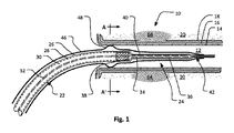
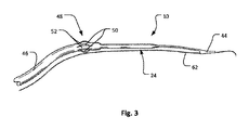
図1および3に戻り、マイクロ波アブレーション装置10を示す。この実施形態では、アブレーション装置10は、腎動脈のマイクロ波除神経術のために使用されるマイクロ波放出カテーテルである。図1において、内側の層(または血管内膜)14、中間の層(つまり血管中膜)16、および外側の層(または血管外膜)18といった種々の動脈壁によって形成された血管、例えば、腎動脈12の中のマイクロ波アブレーション装置10を示す。血管外膜18に隣接して、この実施形態においてアブレーションされる腎神経20が通っている。
Returning to FIGS. 1 and 3, the
装置10は腎動脈の除神経術に関して説明されているが、装置を他の医療用アブレーションの応用で使用することができることを当業者は理解するであろう。
Although
マイクロ波アブレーション装置10は、使用時に、エネルギー源(図示せず)、特にマイクロ波エネルギー源に接続される供給ライン22を含む。供給ライン22は、マイクロ波エネルギーを周辺環境に放射する単一の放射素子を有するラジエータ24(またはアンテナ)内で終端する。下の説明からより明らかになるように、マイクロ波エネルギーが周辺部位に伝導され、吸収が熱を生み出す。この熱を血流が迅速に散逸させ、動脈壁の内膜および中膜層14および16を保護し、腎動脈外膜層18およびより深い範囲の優先的な加熱をもたらし、それによって腎動脈12に対してより深い範囲に位置する腎神経20をアブレーションする。
The
供給ライン22は、ケーブル、例えば、同軸ケーブルであり得、これは、外側の層から内側の層に、絶縁外側シース26、外側導電シールド28、管状絶縁層30、および導電コア(内側導体とも呼ばれる)32を含むことでよく知られている。
The
ラジエータ24は、供給ライン22の直径より常に小さく、供給ライン22と同軸である直径を有する放射素子34を有する。放射素子は、供給ライン22の導電コア32の延長部分であるため、導電コア32と同じ直径である一定直径を有する。参照番号38によって示される、ラジエータ24と供給ライン22との間の「接合部」は、外側導電シールド28が終端する所である。放射素子34は、周辺環境から電気絶縁されている。例えば、放射素子34は、参照番号36によって図1に示される絶縁材料の中に囲繞され得る。放射素子34は、代替的に、絶縁材料の層によって被覆され得るか、またはその中に囲繞され得る。絶縁材料は、PTFE(例えば、テフロン(登録商標))であってもよいが、特定の温度に耐える任意の他の好適な電気絶縁材料、例えば、フッ化エチレンポリマー(FEP:fluorinated ethylene polymer)が使用されてもよい。
The
供給ライン22とラジエータ24との間の接合部38において、外側導電シールド28は終端し、絶縁用の構造的支持構成要素40によってシールされている。構造的支持構成要素40を最適に読み取れる図6A〜6Cに関して下でより詳細に説明されるように、この構成要素40は、装置10に接合部での構造的支持および可撓性を提供し、ラジエータ24のカバーとして作用する。
At the
装置10は、供給ライン22の遠位端部で外側導電シールドに装着されるチョーク部を有しない。このため、導電コアが、電磁妨害なしでラジエータまで延在する。さらに、放射素子24の遠位端部には、エンドキャップも、5/8λコイルまたはラジエータ24に装着されるインピーダンス整合用の任意の他の構造体も存在しない。チョーク部を有しない結果として、ラジエータは、除神経術が行われるラジエータからのラジアル距離において比較的により多くのエネルギーを放射する。これは、放射素子に装着されるエンドキャップまたはコイルを有しないことによってさらに助成される。対照的に、かかるチョーク部を含めると、エンドキャップまたはコイルが放射素子に装着される場合はさらに、放射パターンが放射素子により近く集中することになる。かかるエンドキャップは、種々の形態をとってもよいが、実際には、容量をラジエータ素子に付加し得る。例えば、エンドキャップは、放射素子の遠位先端に電気接続され、そこから、放射素子のいくつかの遠位区分上で近位方向に、しかし放射素子から半径方向に絶縁されて供給し得る。一方、かかるコイルは、典型的に、一端部では外側導電シールドに接続され、他端部では放射素子の長さ方向に沿った位置、例えば、接合部38から約5/8λの位置に接続される。
The
電気シールド(地表面など)または外側導電シールドから横に延在するラジアルも存在しない。かかるシールドおよびラジアルを除外することによって、不必要なバルクが追加されないように、またはアブレーション装置が配置される血管を妨害しないように、装置の最大直径が最小限に抑えられる。 There are also no radials extending laterally from the electrical shield (such as the ground surface) or the outer conductive shield. By excluding such shields and radials, the maximum diameter of the device is minimized so as not to add unnecessary bulk or interfere with the blood vessels in which the ablation device is located.
チョーク部、コイル、地表面、ラジアル、エンドキャップ、または任意の他のかかる構造体を含まず、装置は、外側導電シールド28上の負荷と導電コア32(導電コア32の放射素子34部分を含む)とが整合しないという点において著しく「不平衡」である。これは、これらの構造体を使用して、アンテナをファーフィールドにおいて最小の電力損失および伝導効率で生み出す従来のアンテナ設計の実践とは対照的である。
Not including chokes, coils, ground surfaces, radials, end caps, or any other such structure, the device includes a load on the outer
また、絶縁される放射素子34によって、エネルギーを、交流電流(オーム加熱)を通じて周辺環境、すなわち、腎動脈12の中を流れる血管または後で説明される他の潅注流体に散逸させることができない。したがって、放射素子24からの唯一のエネルギー散逸は、放射によるものである。下で明らかになるように、これらの因子は、導電シールド28の中の循環電流(渦電流)による供給ライン22に沿ったエネルギーの比較的により高い損失を犠牲にして、アブレーションされる部位全域のより好ましい加熱パターンおよびより高い展開可能性と、結果的により大きい供給ライン22の加熱とをもたらす。加熱パターンの有利性の一部は、(地表面、チョーク部、コイル、および/またはエンドキャップが用いられる場合のように)ラジエータの一端部でホットスポットとして集中するのではなく、ラジエータのより長い長さ方向にわたって、ニアフィールドにおいて概して広がることである。これは、血管周囲神経をアブレーションすることができるより長い長さを提供することをもたらす。これは、神経再生が機能的接続を再確立するためにブリッジする必要がある間隔を広げることによって、除神経術の施術の耐久性を改善し得る。
Also, the insulated
カバー40は、カバー40または外側シース46の装着部または延長部であり得る構成要素42を運送し得る。構成要素42は、血管形成ワイヤ(例えば、0.014インチの血管形成ワイヤ)を追跡するためのモノレールセグメント44を運送する。構造的支持カバーは、供給ライン22の外側の層の終端部の上をラジエータ24の先端まで(およびそれを越えて)延在し得る。一実施形態例では、カバー40は、その熱収縮可能な特徴によりポリオレフィン材料から製造され、それによって緊密な嵌合を作り出す。しかしながら、PTFE(テフロン(登録商標))またはFEPなどの他の高温プラスチックなどの他の好適な材料を使用することができることが理解されるであろう。
The
図1に示す実施形態では、装置10の一部は、外側装置シース46の中に収容されている。シース46は、典型的に、柔軟かつ薄い好適な材料、例えば、概して人体の中で安全に使用することができるポリオレフィンなどのポリマーから製造される。
In the embodiment shown in FIG. 1, a part of the
シース46は、この実施形態では、センタリング機構として作用し、シース46の部分に沿ってスプライン52の区分(図2および3参照)を形成する、シース46の長さ方向に沿った直線スリット50(図2および3において最適に示される)によって形成されている位置形成部48を含む。スプライン52が柔軟であるため、供給ライン22がシース46に対して移動されると、スプライン52は拡張によって展開されて、動脈12の内壁14に対して凸状突出部を形成する。次いで、位置形成部が、シース46を固設し、中心に位置させ、それによってラジエータ24および供給ライン22を適所に配置する。したがって、位置形成部48は、局部動脈壁14との接触圧力および同軸度を維持するように調整する。機構の折り畳みは、単に外側装置シース46を引き戻すことによって保証される。
In this embodiment, the
外側装置シース46は、使用中に潅注液体および冷却液体が供給ライン22の絶縁外側シース26と外側装置シース46との間を通過することを許容するのに足りるほどにサイズ決めされる。すなわち、外側装置シース46は、供給ライン22と比較して十分な直径を有する。典型的に、生理食塩水水溶液は、それが位置形成部48で動脈12の中に出るように、シース46の中におよびそれを通じて圧送される。生理食塩水水溶液が供給ライン22の長さ方向に沿って流れるにつれて、熱が装置10から除去され、任意の臨床的に重要な温度上昇が確実に対処され、血液のカテーテル管腔がクリアな状態を維持して、血栓を回避する。
The
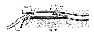
図4および5A〜5Cに移ると、マイクロ波アブレーション装置60の別の実施形態例が示される。装置60は、装置10と同じまたは同様の特徴を有し、これらの特徴は、それに合うように、図1〜3で使用されたものと同じ参照番号によって示される。また、装置10同様、装置60は、地表面、チョーク部、コイル、またはエンドキャップを有しない。しかしながら、装置60の外側装置シース46は、放射素子24の自由先端(およびコネクタ)に向かって位置する遠位の位置形成部48.2と、供給ライン22の一部により近いまたはそれに隣接する近位の形成部48.1との2つの位置形成部48.1と48.2とを提供するように適合されている。これらの位置形成部48.1および48.2の各々は、センタリング機構の一部として作用し、シース46の部分に沿ってスプライン52のそれぞれの区分を形成する、外側装置シース46の長さ方向に沿った直線スリット50によって形成される。再び、外側装置シース46に対する近位方向における供給ライン22の相対的な移動(すなわち、大動脈に向かう移動)を使用して、スプラインのこれらの区分を位置形成部48.1および48.2の凸状突出部に展開し、各々が、外側装置シース46が供給ライン22に対して移動される量に応じて特定の血管(動脈)サイズまで拡張することを許容する。図5A〜5Cで最適に示されるように、2つの位置形成部48.1および48.2は、それらの設計によって局部動脈壁との等しい接触圧力および同軸度を維持するように自己調整する。拡張中、一方の位置形成部が他方より前に最初に拡張する可能性が高い。しかしながら、最初の位置形成部は、血管壁に接触するとすぐにその壁によって拘束され、次いで、他方の位置形成部は、それが同様に同じ圧力をその壁に提供するまで拡張する。これは、自然または病的狭窄または膨張の局部における血管への外傷リスクを最小限に抑える。
Moving on to FIGS. 4 and 5A-5C, another embodiment of the
位置形成部48.1および48.2の折り畳みは、外側装置シース46を供給ライン22に対して近位方向に単に移動することによって管理される。形成部48.1および48.2を折り畳むこの方法は、装置60を除去する前にその直径を低減するための安全な方法と考慮されるものを提供する。
The folding of the position forming portions 48.1 and 48.2 is controlled by simply moving the
図1〜3に関連する説明と同様に、生理食塩水水溶液などの潅注液体がシース46の中に圧送され、この実施形態では、生理食塩水水溶液は、供給ライン22上を通過するだけでなく、絶縁材料36によって収容されるような放射素子34の長さ方向の大部分に沿っても通過する。これは、マイクロ波エネルギーの放射によって引き起こされる局部的な熱の除去ならびに装置の不平衡な性質を助ける。外側装置シース46と動脈12の内壁14(すなわち、腎動脈の内腔表面)との間を血液が流れ、これが、アブレーション工程中にさらなる(および二次的な)局部冷却を許容することがさらに理解されるであろう。この血液の流れは、腎神経を収容するより深い範囲(例えば、外側または外膜層を含む)がアブレーションされる間、動脈12の内膜および中膜(内側および中間)層16および18を保護する。
Similar to the description related to FIGS. 1-3, an irrigation liquid such as a saline solution is pumped into the
柔軟な外側装置シース46は、供給ライン22の遠位端部またはラジエータ24の遠位端部に装着(固設)される。しかしながら、外側シース46は、別様に、少なくとも供給ライン22に対して外側装置シース46の相対的な移動を許容するとともに、位置形成部(複数可)のセンタリング機構が適切に拡張されたときに供給ライン22およびラジエータ24の潅注を許容するために、供給ライン22に対して自由に移動することができる。2つの形成部48.1および48.2(例えば、図4、5、8、または9)を提供する場合、柔軟な外側シース46は、供給ライン22ではなくラジエータ24の遠位端部に装着される。
The flexible
上で言及のように、装置は、従来の血管形成ワイヤ62上での装置の送達を可能にするモノレールセグメント44において終端し得る。この血管形成ワイヤ62は、図3、5A、および5Bに示される。展開およびアブレーションの前に、血管形成ワイヤは、マイクロ波放射を妨害しないように回収される。
As mentioned above, the device may be terminated at a
供給ラインおよびラジエータの製造
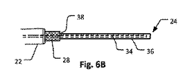
一実施形態例では、装置の供給ライン22は、RG178同軸ケーブルから形成される。周知のように、これは、およそ1.83mmの直径+/−0.03mmの外側FEPシース(すなわち、絶縁外側シース26)、銀メッキ銅ブレード(すなわち、外側導電シールド28)、0.86mmの外径のPTFE絶縁体層(すなわち、管状絶縁層30)、および銀被覆銅クラッドスチールワイヤの7つのストランドからなる0.3mmの直径の中心コア(導電性コア32)からなる。
Manufacture of Supply Line and Radiator In one embodiment, the
言及のように、他の材料を供給ライン22用に使用してもよいが、それらはより大きい直径またはより小さい直径を有し得ることが理解されるであろう。より小さい直径の供給ラインは、特に導電コア32の直径(これは、ラジエータ24の放射素子34も形成する)が小さすぎる場合、除神経術のために必要な電力出力を送達することができない可能性がある。対照的に、直径がより大きい場合、マイクロ波アブレーション装置は、より低い可撓性であり得、より困難な使用および発熱の増加をもたらす血管の中でより広い空間を占有し得る。1.8mmのケーブルから2.2mmのケーブルへのスケールアップにより、心臓病専門医などの医療専門家がそれを使用しないことを選択できるポイントまで可撓性を低減することができることが期待される。導電コアのタイプもまた、装置の使い易さに影響を与えることが判明している。例えば、ケーブルを、RG178ケーブルの7つのストランドではなく、単一のスチールワイヤコアを有する供給ライン22および放射素子34として使用する場合、マイクロ波アブレーション装置の相対的な剛性は、装置を血管の変化に適合させることがあまりにも困難であり得るポイントまで増加する。
As mentioned, other materials may be used for the
この例では、ラジエータ24は、約23mmの距離について、供給ライン22の終端部から、FEPシース(すなわち、絶縁外側シース26)および銅ブレード(すなわち、外側導電シールド28)を除去することによって形成される。これにより、言及のような約0.86mmの直径のPTFE絶縁体(すなわち、管状絶縁層30)が露出される。PTFE絶縁体は、柔軟で可撓性であり、ラジエータの絶縁層36を形成する。この接合部38における、完全同軸ケーブル(供給ライン22)からPTFE絶縁体までの遷移は急激であるため、これは、装置を動脈の中に置く際の困難さの原因になり得る、装置内の潜在的な構造的脆弱性をもたらす。例えば、その急激さは、装置10、60が角部の周りではラジエータ24の先端に追従しないが、代わりに屈曲ポイントで急激に屈曲し、対象部位の中にさらに前進することを拒否する潜在的な屈曲ポイントの原因になり得る。
In this example, the
接合部は、上記の構造的支持構成要素40を追加することによって強化される。例えば、熱収縮可能であり得る小さな管片が、供給ライン22の一部分の周りに巻き付けられる。典型的には、FEPシース(すなわち、絶縁外側シース26)を約3mm除去し、銅ブレード(すなわち、外側導電シールド28)を露出させる。次いで、ポリオレフィン(または他の好適な材料)のチューブの形態の構造的支持構成要素が、露出した銅ブレード(すなわち、外側導電シールド28)の上に置かれ、PTFE絶縁体(すなわち、管状絶縁層30)に重ねられ、外側シース26の終端ポイントから少なくとも接合部を越えて延在する。チューブは、およそ17mmの長さであり得る。構造的支持構成要素は、供給ライン22およびその外側の層26と、絶縁された放射素子34との間に階段状形成部および/または徐々に先細りになる形状部を提供し得る。構成要素は、接合部38により多くの支持を提供し、腎動脈内への展開中に、このポイントにおけるねじれリスクを低減するように、剛性の遷移をより緩やかにする。
The joint is strengthened by adding the
装置の一実施形態例では、外側シース46を含まない図6A〜6Cで示されるように、構造的支持構成要素40は、アブレーション装置の遠位端部の管状絶縁層30の終端ポイントからラジエータ24の先端まで延在するカバーとして製造される。図6Aに最適に示されるように、構成要素40は、外側導電シールド28の一部の上に延在し、その接合部38における終端部から、絶縁層36によって囲繞された放射素子(radiator element)34まで徐々に先細りになる。言及のように、ラジエータ24のカバーとしてのこの構成要素は、接合部が腎動脈の中に装置を置く工程を妨げず、動脈および装置の損傷リスクを低減するように装置の長さ方向にわたって可撓性を確保することを確実にする。構成要素40の動作の理解を助けるために、図6A〜6Cの装置を、装置が腎動脈に入るときの、その外側シース46を含まない状態で図7に示す。しかしながら、外側シース46が省略されているため、図7は、放射素子の理想的な配置を示していないことに留意されたい。外側シースが含まれていれば、放射素子は、動脈壁に押し付けられるのではなく、(図5Bおよび5Bに示されるように)スプライン52の作用により、動脈の中により好適にセンタリングされるであろう。
In one embodiment of the device, as shown in FIGS. 6A-6C, which does not include the
図9は、本発明のさらなる実施形態による装置80を示す。装置80は、装置80が支持構成要素54も含むことを除き、図3および5A〜5Cの装置60と同じである。支持構成要素54は、ラジエータ24の端部まで延在するのではなく、支持構成要素54の遠位端部41が放射素子34に沿ってほぼ中ほどで終わっていることを除き、支持構成要素40と同じである。これにより、ラジエータ24の長さ方向に沿った階段状の厚さが提供され、ラジエータ24が、その遠位端部において、支持構成要素54の遠位端部41においてよりもより可撓性であることをもたらす。他の実施形態では、ラジエータ24の長さ方向に沿って複数段の厚さが存在し得、かつ/またはカバー54は先細りのプロファイルを有し得る。接合部38における支持構成要素54の先細り、およびラジエータ24に沿った階段状の厚さはそれぞれ、ラジエータ24が、その近位端部においてより、その遠位端部41においてより高い可撓性を備えることに寄与する。
FIG. 9 shows a
より可撓性の遠位端部を有することによって、ラジエータ24は、血管形成ワイヤをより好適に追跡することができ、放射素子34のセンタリングを改善することができる。比較すると、より剛性のラジエータは、放射素子34を血管壁の一方の側に付勢し、ソフトセンタリング(soft centering)スプライン52に過度の力を加え得る。
By having a more flexible distal end, the
図9はまた、モノレールセグメント44に関するさらなる詳細を示す。モノレールセグメントは、この実施形態では、外側シース46の遠位端部39に装着されるか、またはその延長部であり、ラジエータ24の遠位端部43に装着される。ラジエータ24をその近位端部に向かってより剛性にすることも、ラジエータ24に、モノレールに沿って曲げずに押し込むのに十分な構造的完全性を提供する。
FIG. 9 also shows further details regarding the
本明細書に記載のすべての実施形態(但し、図9にのみ図示)では、外側シース46は、より近位方向より、腎動脈内部に位置するであろうカテーテル10、60、80の遠位端部45に向かってより可撓性である。これは、ラジエータ24から約50〜100mmの位置49から外側シース46がより厚いためである。この増加した厚さは、第2の層51を有することによって達成されるか、または押し込みのより大きい伝導がモノレール上でシステムを前進させることを許容する、より剛性の特性を有する別の材料への遷移または接合によって達成される。
In all embodiments described herein (but only shown in FIG. 9), the
外側シース46のより厚い部分は、カテーテルの近位端部(図示せず)の止血弁(図示せず)に固定するために、位置49から後方に延在する。弁を越えて、供給ライン22は、弁および外側シース46に対して引っ張られてスプライン52を突出させ得るか、または押し込まれてスプライン52を収縮させ得る。弁は、生理食塩水水溶液をカテーテルに導入するために使用される入力部を含む。弁は、Yコネクタを含み得、Yのアーム部の一方が入力部として作用する。かかる部品の一例は、Qosina(米国ニューヨーク州ロンコンコマ)によって製造された部品番号80303である。
A thicker portion of the
生理食塩水水溶液は、同軸ケーブル(供給ライン22)と外側シース46との間の空間に沿って入力部位から流れ、スプライン52を生み出す形成部において外側シースの中のスリットから出て来る。アブレーション中のカテーテルの潅注は、カテーテルシャフト内の過剰な温度上昇を回避し、カテーテル内の血液および血栓の侵入を回避する。
The saline solution flows from the input site along the space between the coaxial cable (supply line 22) and the
(相対的により薄い外側シース46を有することによって)カテーテルをその遠位端部に向かって相対的により可撓性にすることは、遠位端部45が、中に押し込まれる動脈の輪郭に追従することを可能にし、カテーテルの残りの部分は、遠位端部45が動脈の中に押し込まれることを可能にするためにより堅い。
Making the catheter relatively more flexible towards its distal end (by having a relatively thinner outer sheath 46) allows the
放射素子の最適な長さは、放射素子のニアフィールド環境およびマイクロ波発生器の動作周波数に依存する。構造的支持構成要素は、提案の動作周波数で最大放射を発生させるラジエータ24および放射素子34の共振長に明らかな変化を必要とし得る。これは、マイクロ波フィールドが結合するラジエータ周りの近くの環境を変化させる構造的支持構成要素によるものである。
The optimum length of the radiating device depends on the near-field environment of the radiating device and the operating frequency of the microwave generator. The structural support component may require a clear change in the resonant length of the
この実施形態では、マイクロ波アブレーション装置10、60、および80は、2.45GHzの周波数で機能するように設計されており、この周波数では、4分の1波の放射素子の長さは、典型的に、約4mmであるはずである。これは、ラジエータ24が血液プール内に位置することを前提としている。電気絶縁を達成するために放射素子上にあるテフロン(登録商標)絶縁体のため、および支持構成要素54のために、放射素子の4分の1波長が約5mm以上に増加する。
In this embodiment, the
半波の放射素子、すなわち、約11mmの長さを選択することもでき、約22mmの長さで代替的に全波の放射素子を選択することもできることが理解されるであろう。しかしながら、全波長を超える放射素子の長さは、素子の先端および根元からの2裂放射(bilobal radiation)などの望ましくない結果の原因となり得る。 It will be appreciated that a half-wave radiating element, i.e. a length of about 11 mm, can be selected, and an alternative full-wave radiating element with a length of about 22 mm can be selected. However, the length of the radiating device beyond all wavelengths can cause undesired consequences such as bilobal radiation from the tip and root of the device.
4分の1波、半波、または全波のラジエータからの放射パターンが等しくないことを当業者は自覚しているであろう。本発明者による実験では、4分の1波の放射素子は、半波の放射素子より少ないエネルギーをニアフィールドの中に放射することが示された。長さおよそ11mmの半波の放射素子の場合、エネルギーがおよそ5mmの帯域で束ねられる一方、全波の放射素子は、放射素子の長さ方向に沿ってより広がったパターンでエネルギーを放射する。このパターンは、ラジエータの中間ポイント近くに集中した整合環境の中で22mm測定用の全波のラジエータについて約15〜19mmの長さを有し得る。 Those skilled in the art will be aware that the emission patterns from quarter-wave, half-wave, or full-wave radiators are not equal. Experiments by the present inventor have shown that a quarter-wave radiating element emits less energy into the near field than a half-wave radiating element. In the case of a half-wave radiating element of about 11 mm in length, the energy is bundled in a band of about 5 mm, while the full-wave radiating element radiates energy in a more widespread pattern along the length direction of the radiating element. This pattern can have a length of about 15-19 mm for a full wave radiator for 22 mm measurements in a concentrated environment near the midpoint of the radiator.
電力レベル
必要な電力はこのシステムの実施形態に依存するため、最適なアブレーションを行うようにカテーテルを駆動するのに必要な電力は広範囲にわたる。これは、供給ラインのエネルギー損失が供給ラインの長さおよび他の因子に依存することが主な原因である。ラジエータによって放出される供給電力の割合は、供給ラインのエネルギー損失に依存する。したがって、カテーテルの長さを最小に保つことによって、より低い印加電力が必要とされる。これは、短い長さの(例えば、およそ80cmの長さのカテーテル供給ラインを使用する)システムについては40〜60W程の低さであり得、(例えば、およそ140cmの長さのカテーテル供給ラインを使用する)より長いシステムについては120〜160W程の高さであり得る。必要とされる適切な電力は、端部ラジエータのマイクロ波出力、腎動脈のサイズ、腎動脈流量、および他の患者因子に依存する。電力出力は、腎神経を収容する腎動脈の血管周囲組織をアブレーションするのに十分高い線量でありながら、動脈壁への損傷を回避するのに十分低い線量のマイクロ波エネルギーを提供するように選択される。実験的に、約3分間にわたるマイクロ波エネルギー線量の送達は、概ね、腎動脈流が(生理食塩水潅注と共に)血管内腔表面を十分に冷たく保ち、通常の生理的条件下での腎動脈壁への損傷をいくらか防ぐことを可能にする。
Power Level The power required depends on the embodiment of this system, so the power required to drive the catheter for optimal ablation is wide-ranging. This is mainly due to the energy loss of the supply line depending on the length of the supply line and other factors. The proportion of power supplied by the radiator depends on the energy loss of the supply line. Therefore, lower applied power is required by keeping the length of the catheter to a minimum. This can be as low as 40-60 W for short length systems (eg, using a catheter supply line of approximately 80 cm in length) and a catheter supply line of approximately 140 cm in length (eg, using a catheter supply line of approximately 140 cm in length). For longer systems (used) it can be as high as 120-160W. The appropriate power required depends on the microwave output of the end radiator, renal artery size, renal artery flow, and other patient factors. The power output is chosen to provide a dose high enough to ablate the perivascular tissue of the renal artery that houses the renal nerve, but low enough to avoid damage to the arterial wall. Will be done. Experimentally, delivery of a microwave energy dose over a period of about 3 minutes generally allows the renal artery flow (with saline irrigation) to keep the surface of the vascular lumen sufficiently cold and the renal artery wall under normal physiological conditions. Allows some prevention of damage to.
潅注
言及のように、生理食塩水洗浄剤/水溶液の形態の潅注液体は、外側装置シース46と供給ライン22との間の流れ、場合によっては絶縁された放射素子24との間の流れとして使用される。生理食塩水水溶液は、一例において、体内に挿入された装置の一部に沿って、約20mL/分の速度で供給される。この供給の目的は、装置ボア内に血餅が形成されるのを回避し、供給ライン22の冷却も提供することである。一実施形態では、供給ライン22の電力定格は空気中で連続的に78Wである。かかる供給ラインについて、マイクロ波アブレーション装置10、60、80は、液体生理食塩水冷却が使用される場合、最大約160Wまで動作することができる。これは、装置が障害なく効果的に動作するのを可能にするのに十分なレベルの冷却を提供する。また、装置の動作中に、腎動脈は、それが生理食塩水水溶液で洗い流されるため、流れによる利益を得ることができる。施術中に、血管(腎動脈)がれん縮する場合があるが、装置を通る生理食塩水水溶液によって引き起こされる保証された流れが、血流のみに依存するためより冷たく動脈壁を保つ。
Irrigation As mentioned, the saline solution / aqueous solution irrigation liquid is used as the flow between the
マイクロ波アブレーション装置の使用
腎動脈12の中のマイクロ波アブレーション装置10、60、80の除神経術使用例では、装置は、腎動脈の小孔に係合するために使用されるガイディングシース内の大腿動脈などの末梢動脈を介して導入される。シース係合の蛍光透視確認、および放射線不透過性造影剤注入による腎動脈の解剖学的定義の後、装置は、腎動脈のセグメントの中に直接的にまたはワイヤ上式のいずれかで導入される。上で言及のように、装置は、従来の血管形成ワイヤの使用を通じて腎動脈12に送達され得る。一旦位置付けされると、位置形成部48.1および48.2は、位置形成部48.1および48.2が腎動脈の内側の層に当接するまで、供給ラインを外側装置シースに対して移動させることによって展開される。センタリングスプラインは、供給ラインと外側装置シースとの間にどの程度相対的な移動が発生するかに依存して、異なる内径の腎動脈の壁に接するように拡張することができる。腎動脈の内径の血管造影による推定は、スプラインの展開前になされ、スプラインの段階的な展開は、動脈損傷を引き起こすことなく装置をセンタリングするように行われる。
Use of Microwave Ablation Device In an example of denervation of
次いで、マイクロ波発生器をおよそ3分間作動させ、その間にマイクロ波が放射素子から放射される。放射素子が絶縁されているため、上で言及にように、交流電流を素子から周囲の生物学的環境に流すことができず、それによって電流によるオームエネルギー損失が抑制される。装置内の生理食塩水水溶液の流れおよび動脈内の血液の継続的な流れにより、腎動脈の内側および中間の層を含むラジエータに直接隣接する部位は、それらのアブレーションが発生しないように十分に冷却される。しかしながら、より深い範囲の冷却がないために、これらの範囲内で実質的な加熱が発生し、アブレーションをもたらす。例えば、図1および4の両方において、アブレーションされた部位は参照番号64で示される。腎動脈アブレーションのマイクロ波ファントムゲルモデル上の装置の基本形のインビトロ試験では、病変部を形成する潜在性を有する実質的な加熱を生み出しつつ、腎動脈管腔に隣接する組織に深さ約1mmの深さを残すことが示された。残される深さは、腎動脈流および他の患者因子の影響を受け、マイクロ波エネルギー送達の線量および電力を変化させることによって制御可能である。したがって、このマイクロ波アブレーション装置は、高周波エネルギープローブ/カテーテルとは異なり、血管管腔からおよそ0.5mmの深さ内にある腎動脈の筋層および内皮表面への重大な損傷がない腎神経の徐神経術が可能であると思われる。さらに、マイクロ波エネルギーからの加熱はカテーテルの接触を必要としないため、周囲病変部を、腎動脈12の外側の層18および腎神経を収容する腎周囲脂肪内のより深い範囲に、本発明の適切にセンタリングされたマイクロ波装置によって送達すること、および潜在的に施術を短縮し、単純化する1つのエネルギー応用によって腎動脈の除神経術を行うことが可能である。
The microwave generator is then operated for approximately 3 minutes, during which time microwaves are emitted from the radiating element. Due to the insulation of the radiating device, as mentioned above, alternating current cannot flow from the device to the surrounding biological environment, thereby suppressing ohm energy loss due to the current. Due to the flow of saline solution in the device and the continuous flow of blood in the arteries, the sites directly adjacent to the radiator, including the medial and intermediate layers of the renal arteries, are sufficiently cooled to prevent their ablation. Will be done. However, due to the lack of cooling in deeper ranges, substantial heating occurs within these ranges, resulting in ablation. For example, in both FIGS. 1 and 4, the ablated site is indicated by reference number 64. In a basic in vitro test of the device on a microwave phantom gel model of renal artery ablation, a depth of approximately 1 mm in the tissue adjacent to the renal artery lumen while producing substantial heating with the potential to form lesions. It was shown to leave depth. The depth left is influenced by renal arterial flow and other patient factors and can be controlled by varying the dose and power of microwave energy delivery. Therefore, unlike high frequency energy probes / catheters, this microwave ablation device does not cause significant damage to the muscularis and endothelial surface of the renal arteries within a depth of approximately 0.5 mm from the vascular lumen of the renal nerve. Lumen surgery seems to be possible. In addition, heating from microwave energy does not require catheter contact, so the peripheral lesions are located in the
基本形例
腎動脈の我々の縦方向モデル72の中に位置付けられたマイクロ波アブレーション装置70の基本形を図8に示す。これは、人の腎動脈内の通常の流れである0.5L/分の速度で流れる37℃の0.9%の生理食塩水水溶液で充填されたマイクロ波ゲルファントム材料内のトンネル(すなわち、管腔)74からなっていた。ファントム材料内には、50℃〜78℃の温度で色を変化させる感温液晶シート76が埋め込まれており、写真による熱病変部の評価および色−温度変換のための社内構築ソフトウェアが可能である。供給ラインは、137cmの長さの50Ωの同軸ケーブルからなっていた。マイクロ波アブレーション装置70を腎動脈のモデル72の管腔74の中に導入し、2.45GHzのアブレーションを、140Wの電力で180秒間行い、参照番号78によって示される最終病変部を得た。当業者によって理解されるように、図8に示されるような病変部の細長い形状は、放射パターンの細長い形状の視覚的表示である。53℃は、これを超えると細胞死が発生する一般に受け入れられているおよその温度であり、感温液晶シートは、赤色と緑色との間の遷移としてこの温度帯を表示する。マイクロ波アブレーションは、最初の1〜2mmを残し、モデル化された腎動脈管腔の表面に対して約5〜6mmの深さまで延在していることを観察することができる。これは、そのほとんどが血管管腔から1〜6mmに存在する腎神経の大部分に熱損傷を与えるのに十分であり、血管の内膜および最初のおよそ0.5mm内にある中膜を残す。
Example of basic form FIG. 8 shows the basic form of the microwave ablation device 70 positioned in our longitudinal model 72 of the renal artery. This is a tunnel (ie, a tunnel) in a microwave gel phantom material filled with a 0.9% saline solution at 37 ° C. that flows at a rate of 0.5 L / min, which is the normal flow in a person's renal arteries. It consisted of a lumen) 74. A temperature-sensitive
生体内での使用方法
本発明のカテーテル10、60、80が腎動脈の除神経術のために使用され得る例示的な方法は、以下のステップを伴う。
1.血管ガイドシース(図示せず)を、患者の末梢動脈、通常は大腿動脈の中に挿入する。腎動脈に係合するように形作られた任意の既存の屈折性または非屈折性のガイドシースを使用することができる。
2.全身抗凝固を患者に行い、血管内血栓を回避する。
3.0.014”の血管形成ワイヤを、カテーテル先端の短いモノレールセグメント44に装填する。
4.カテーテルを、ガイドシースの中に導入する前に、高流量(約60mL/分)で潅注しながら生理食塩水で洗い流し、脱気する。洗い流した後、潅注を30〜60mL/分で維持する。
5.マイクロ波アブレーションカテーテルを、その先端が血管シースの遠位端部に到達するように腎動脈内に係合した後、血管ガイドシースを介して導入する。
6.血管形成ワイヤを、腎動脈またはその分岐部へと下方に前進させ、血管造影的にガイドする。
7.アブレーションカテーテルを、アブレーション対象の部位まで、血管形成ワイヤの上でモノレール式に下方に進める。
8.血管形成ワイヤを回収する。
9.センタリングスプラインを、カテーテルの内側同軸ケーブル部分(供給ライン22)を引っ張ることによって展開する。供給ライン22の変位の程度により、センタリングスプラインが突出する程度を決定する。これにより、血管造影で評価した血管と同じサイズに適合させることができる。
10.放射素子のセンタリングを、直交透視図で確認する。
11.アブレーションを行う(例えば、120〜160Wで3分間)。
12.スプラインを、シース46に対して供給ライン22を押し込むことによって折り畳む。
13.カテーテルを回収する。所望の場合、カテーテルが動脈内のより近位の位置にあるときにスプラインを再展開することによって、腎動脈内のより近位方向のさらなるアブレーションを行うことができる。
In-vivo Use An exemplary method in which the
1. 1. A vascular guide sheath (not shown) is inserted into the patient's peripheral arteries, usually the femoral artery. Any existing refractive or non-refractive guide sheath shaped to engage the renal arteries can be used.
2. Perform systemic anticoagulation on the patient to avoid endovascular thrombosis.
A 3.0.104 "angiogenic wire is loaded into the
4. Before introducing the catheter into the guide sheath, rinse with saline and degas while irrigating at a high flow rate (approximately 60 mL / min). After rinsing, irrigation is maintained at 30-60 mL / min.
5. A microwave ablation catheter is introduced through the vascular guide sheath after engaging into the renal artery so that its tip reaches the distal end of the vascular sheath.
6. The angioplasting wire is advanced downward to the renal artery or its bifurcation and angiographically guided.
7. The ablation catheter is monorailed downward on the angioplasty wire to the site to be ablated.
8. Collect the angioplasty wire.
9. The centering spline is deployed by pulling on the inner coaxial cable portion (supply line 22) of the catheter. The degree to which the centering spline protrudes is determined by the degree of displacement of the
10. Confirm the centering of the radiating element with an orthogonal perspective view.
11. Perform ablation (eg, 120-160 W for 3 minutes).
12. The spline is folded by pushing the
13. Collect the catheter. If desired, further proximal ablation within the renal artery can be performed by redeploying the spline when the catheter is in a more proximal position within the artery.
本発明のマイクロ波アブレーション装置は、使用時に、単一のエネルギー応用を許容する効果的な加熱パターンを許容するように構成されており、加熱パターンは放射素子の長さの大部分にわたって広がっている。さらに、加熱パターンは、放射素子が均衡しており、かつ/またはチョーク部および/もしくは地表面によって供給ラインから電磁的に遮断されたものよりも、より広がっている(より少ない円形/より細長い)。装置はまた、除神経術が依然として行われる間、高電力を使用できるように供給ラインの十分な冷却を許容しつつ、腎動脈流および洗浄剤流が動脈の内側の層の熱損傷からの保護を確実にするように構成されている。手動で展開して折り畳むことができる位置形成部の一部としての柔軟なスプラインの使用によって、カテーテルを腎動脈内でセンタリングする際に血管壁に及ぶ力がより制御され、段階的になり、したがって血管外傷の可能性が低減される。 The microwave ablation apparatus of the present invention is configured to allow an effective heating pattern that allows a single energy application in use, and the heating pattern extends over most of the length of the radiating element. .. In addition, the heating pattern is more widespread (less circular / elongated) than those in which the radiating elements are balanced and / or electromagnetically blocked from the supply line by the choke and / or ground surface. .. The device also protects the renal artery flow and detergent flow from thermal damage in the inner layers of the artery, while allowing sufficient cooling of the supply line to allow high power to be used while denervation is still performed. Is configured to ensure. The use of flexible splines as part of a position-forming site that can be manually unfolded and folded allows the force exerted on the vessel wall as it is centered within the renal artery to be more controlled and gradual, thus The possibility of vascular trauma is reduced.
本明細書で開示および定義の本発明は、文脈または図面から言及されるかまたは明らかである個別の特徴のうちの2つ以上のすべての代替的な組み合せに及ぶことが理解されるであろう。これらの異なる組み合わせはすべて、本発明の種々の代替的な態様を構成する。 It will be appreciated that the invention disclosed and defined herein spans all alternative combinations of two or more of the individual features referred to or apparent from the context or drawings. .. All of these different combinations constitute various alternative aspects of the invention.
Claims (15)
前記供給ラインは、前記マイクロ波ラジエータとの接合部を有し、前記接合部において終端し絶縁された外側導電シールドを有し、
前記供給ラインは、前記マイクロ波ラジエータまで延在する導電コアを有し、前記導電コアの一部は、遠位端部で、その周辺環境から電気絶縁された前記マイクロ波ラジエータを形成し、
前記マイクロ波ラジエータが前記供給ラインのインピーダンスと整合せず、かつ、前記遠位端部で不平衡である、マイクロ波アブレーション装置。 A microwave ablation device that includes a supply line, a microwave radiator, and a device outer sheath in which at least a portion of the supply line is housed, through which the device outer sheath irrigates liquid during use. Allows the flow of
The supply line has a junction with the microwave radiator and has an outer conductive shield terminated and insulated at the junction.
The supply line has a conductive core that extends to the microwave radiator, and a portion of the conductive core forms the microwave radiator at its distal end, which is electrically insulated from its surrounding environment.
A microwave ablation device in which the microwave radiator is inconsistent with the impedance of the supply line and is unbalanced at the distal end.
Applications Claiming Priority (3)
| Application Number | Priority Date | Filing Date | Title |
|---|---|---|---|
| AU2015902225 | 2015-06-12 | ||
| AU2015902225A AU2015902225A0 (en) | 2015-06-12 | Microwave ablation device | |
| PCT/AU2016/050480 WO2016197206A1 (en) | 2015-06-12 | 2016-06-10 | Microwave ablation device |
Publications (3)
| Publication Number | Publication Date |
|---|---|
| JP2018522692A JP2018522692A (en) | 2018-08-16 |
| JP2018522692A5 JP2018522692A5 (en) | 2021-06-10 |
| JP6913673B2 true JP6913673B2 (en) | 2021-08-04 |
Family
ID=57502802
Family Applications (1)
| Application Number | Title | Priority Date | Filing Date |
|---|---|---|---|
| JP2018516609A Active JP6913673B2 (en) | 2015-06-12 | 2016-06-10 | Microwave ablation device |
Country Status (7)
| Country | Link |
|---|---|
| US (1) | US11039884B2 (en) |
| EP (1) | EP3307384B1 (en) |
| JP (1) | JP6913673B2 (en) |
| CN (1) | CN107921274B (en) |
| AU (1) | AU2016275576B2 (en) |
| CA (1) | CA2988609C (en) |
| WO (1) | WO2016197206A1 (en) |
Families Citing this family (5)
| Publication number | Priority date | Publication date | Assignee | Title |
|---|---|---|---|---|
| TWI640291B (en) * | 2016-12-16 | 2018-11-11 | 巽晨國際股份有限公司 | Electromagnetic wave treatment device and method of use thereof |
| CN110494093B (en) | 2017-01-26 | 2023-03-28 | 堃博生物科技公司 | Bronchoscope-based microwave ablation system and method |
| WO2020014746A1 (en) * | 2018-07-19 | 2020-01-23 | The University Of Sydney | Ablation lesion device |
| CA3105886A1 (en) * | 2018-08-13 | 2020-02-20 | The University Of Sydney | Catheter ablation device with impedance monitoring |
| WO2020033999A1 (en) | 2018-08-13 | 2020-02-20 | The University Of Sydney | Catheter ablation device with temperature monitoring |
Family Cites Families (16)
| Publication number | Priority date | Publication date | Assignee | Title |
|---|---|---|---|---|
| GB250673A (en) * | 1925-01-16 | 1926-04-16 | George Ogilby Fox Lane | Improved construction of plug and socket connections for electrical purposes |
| JPH08187297A (en) | 1995-01-11 | 1996-07-23 | Olympus Optical Co Ltd | Microwave treatment device |
| US6210367B1 (en) | 1995-09-06 | 2001-04-03 | Microwave Medical Systems, Inc. | Intracorporeal microwave warming method and apparatus |
| US6610083B2 (en) * | 1998-08-24 | 2003-08-26 | Radiant Medical, Inc. | Multiple lumen heat exchange catheters |
| US6645199B1 (en) | 1999-11-22 | 2003-11-11 | Scimed Life Systems, Inc. | Loop structures for supporting diagnostic and therapeutic elements contact with body tissue and expandable push devices for use with same |
| US8945111B2 (en) | 2008-01-23 | 2015-02-03 | Covidien Lp | Choked dielectric loaded tip dipole microwave antenna |
| US8059059B2 (en) | 2008-05-29 | 2011-11-15 | Vivant Medical, Inc. | Slidable choke microwave antenna |
| EP2349045B1 (en) * | 2008-10-21 | 2014-07-16 | Microcube, LLC | Devices for applying energy to bodily tissues |
| GB2472972A (en) * | 2009-07-20 | 2011-03-02 | Microoncology Ltd | A microwave antenna |
| US8382750B2 (en) * | 2009-10-28 | 2013-02-26 | Vivant Medical, Inc. | System and method for monitoring ablation size |
| WO2011060200A1 (en) * | 2009-11-11 | 2011-05-19 | Innovative Pulmonary Solutions, Inc. | Systems, apparatuses, and methods for treating tissue and controlling stenosis |
| EP3175808B1 (en) * | 2010-04-26 | 2019-08-21 | Medtronic Ardian Luxembourg S.à.r.l. | Catheter apparatuses and systems for renal neuromodulation |
| EP2632379B1 (en) * | 2010-10-25 | 2022-03-09 | Medtronic Ireland Manufacturing Unlimited Company | Microwave catheter apparatuses for renal neuromodulation |
| US9358066B2 (en) * | 2011-04-08 | 2016-06-07 | Covidien Lp | Flexible microwave catheters for natural or artificial lumens |
| GB2503673A (en) * | 2012-07-03 | 2014-01-08 | Creo Medical Ltd | Electrosurgical device with convex under surface |
| US10076384B2 (en) * | 2013-03-08 | 2018-09-18 | Symple Surgical, Inc. | Balloon catheter apparatus with microwave emitter |
-
2016
- 2016-06-10 JP JP2018516609A patent/JP6913673B2/en active Active
- 2016-06-10 CN CN201680034334.8A patent/CN107921274B/en active Active
- 2016-06-10 WO PCT/AU2016/050480 patent/WO2016197206A1/en active Application Filing
- 2016-06-10 US US15/580,615 patent/US11039884B2/en active Active
- 2016-06-10 AU AU2016275576A patent/AU2016275576B2/en active Active
- 2016-06-10 EP EP16806449.1A patent/EP3307384B1/en active Active
- 2016-06-10 CA CA2988609A patent/CA2988609C/en active Active
Also Published As
| Publication number | Publication date |
|---|---|
| AU2016275576A1 (en) | 2018-01-04 |
| EP3307384A1 (en) | 2018-04-18 |
| EP3307384A4 (en) | 2019-02-20 |
| EP3307384B1 (en) | 2020-08-05 |
| CA2988609C (en) | 2023-09-05 |
| US20180221089A1 (en) | 2018-08-09 |
| CA2988609A1 (en) | 2016-12-15 |
| US11039884B2 (en) | 2021-06-22 |
| AU2016275576B2 (en) | 2020-08-20 |
| WO2016197206A1 (en) | 2016-12-15 |
| CN107921274A (en) | 2018-04-17 |
| JP2018522692A (en) | 2018-08-16 |
| CN107921274B (en) | 2020-08-04 |
Similar Documents
| Publication | Publication Date | Title |
|---|---|---|
| JP6913673B2 (en) | Microwave ablation device | |
| US11963718B2 (en) | Microwave catheter apparatuses, systems, and methods for renal neuromodulation | |
| EP3001971B1 (en) | Flexible microwave catheters for natural or artificial lumens | |
| US6319251B1 (en) | Medical device and methods for treating intravascular restenosis | |
| US20120197246A1 (en) | Ablation catheter | |
| US9173696B2 (en) | Self-positioning electrode system and method for renal nerve modulation | |
| AU2015202149B2 (en) | Flexible microwave catheters for natural or artificial lumens | |
| JP2021532848A (en) | Catheter ablation device with impedance monitoring | |
| JP2021532847A (en) | Catheter ablation device with temperature monitoring |
Legal Events
| Date | Code | Title | Description |
|---|---|---|---|
| A521 | Request for written amendment filed |
Free format text: JAPANESE INTERMEDIATE CODE: A523 Effective date: 20180517 |
|
| A521 | Request for written amendment filed |
Free format text: JAPANESE INTERMEDIATE CODE: A523 Effective date: 20180525 |
|
| A621 | Written request for application examination |
Free format text: JAPANESE INTERMEDIATE CODE: A621 Effective date: 20190610 |
|
| A977 | Report on retrieval |
Free format text: JAPANESE INTERMEDIATE CODE: A971007 Effective date: 20200821 |
|
| A131 | Notification of reasons for refusal |
Free format text: JAPANESE INTERMEDIATE CODE: A131 Effective date: 20200825 |
|
| A521 | Request for written amendment filed |
Free format text: JAPANESE INTERMEDIATE CODE: A523 Effective date: 20201124 |
|
| A131 | Notification of reasons for refusal |
Free format text: JAPANESE INTERMEDIATE CODE: A131 Effective date: 20210126 |
|
| A524 | Written submission of copy of amendment under article 19 pct |
Free format text: JAPANESE INTERMEDIATE CODE: A524 Effective date: 20210423 |
|
| TRDD | Decision of grant or rejection written | ||
| A01 | Written decision to grant a patent or to grant a registration (utility model) |
Free format text: JAPANESE INTERMEDIATE CODE: A01 Effective date: 20210615 |
|
| A61 | First payment of annual fees (during grant procedure) |
Free format text: JAPANESE INTERMEDIATE CODE: A61 Effective date: 20210712 |
|
| R150 | Certificate of patent or registration of utility model |
Ref document number: 6913673 Country of ref document: JP Free format text: JAPANESE INTERMEDIATE CODE: R150 |