JP6913172B2 - Wireless signal transmission / reception methods and devices in wireless communication systems - Google Patents
Wireless signal transmission / reception methods and devices in wireless communication systems Download PDFInfo
- Publication number
- JP6913172B2 JP6913172B2 JP2019542447A JP2019542447A JP6913172B2 JP 6913172 B2 JP6913172 B2 JP 6913172B2 JP 2019542447 A JP2019542447 A JP 2019542447A JP 2019542447 A JP2019542447 A JP 2019542447A JP 6913172 B2 JP6913172 B2 JP 6913172B2
- Authority
- JP
- Japan
- Prior art keywords
- harq
- data
- delay
- processing time
- scs
- Prior art date
- Legal status (The legal status is an assumption and is not a legal conclusion. Google has not performed a legal analysis and makes no representation as to the accuracy of the status listed.)
- Active
Links
Images


Classifications
-
- H—ELECTRICITY
- H04—ELECTRIC COMMUNICATION TECHNIQUE
- H04L—TRANSMISSION OF DIGITAL INFORMATION, e.g. TELEGRAPHIC COMMUNICATION
- H04L1/00—Arrangements for detecting or preventing errors in the information received
- H04L1/12—Arrangements for detecting or preventing errors in the information received by using return channel
- H04L1/16—Arrangements for detecting or preventing errors in the information received by using return channel in which the return channel carries supervisory signals, e.g. repetition request signals
- H04L1/18—Automatic repetition systems, e.g. Van Duuren systems
- H04L1/1812—Hybrid protocols; Hybrid automatic repeat request [HARQ]
-
- H—ELECTRICITY
- H04—ELECTRIC COMMUNICATION TECHNIQUE
- H04L—TRANSMISSION OF DIGITAL INFORMATION, e.g. TELEGRAPHIC COMMUNICATION
- H04L1/00—Arrangements for detecting or preventing errors in the information received
- H04L1/12—Arrangements for detecting or preventing errors in the information received by using return channel
- H04L1/16—Arrangements for detecting or preventing errors in the information received by using return channel in which the return channel carries supervisory signals, e.g. repetition request signals
- H04L1/18—Automatic repetition systems, e.g. Van Duuren systems
- H04L1/1829—Arrangements specially adapted for the receiver end
- H04L1/1854—Scheduling and prioritising arrangements
-
- H—ELECTRICITY
- H04—ELECTRIC COMMUNICATION TECHNIQUE
- H04L—TRANSMISSION OF DIGITAL INFORMATION, e.g. TELEGRAPHIC COMMUNICATION
- H04L1/00—Arrangements for detecting or preventing errors in the information received
- H04L1/12—Arrangements for detecting or preventing errors in the information received by using return channel
- H04L1/16—Arrangements for detecting or preventing errors in the information received by using return channel in which the return channel carries supervisory signals, e.g. repetition request signals
- H04L1/18—Automatic repetition systems, e.g. Van Duuren systems
- H04L1/1867—Arrangements specially adapted for the transmitter end
- H04L1/1874—Buffer management
-
- H—ELECTRICITY
- H04—ELECTRIC COMMUNICATION TECHNIQUE
- H04L—TRANSMISSION OF DIGITAL INFORMATION, e.g. TELEGRAPHIC COMMUNICATION
- H04L5/00—Arrangements affording multiple use of the transmission path
-
- H—ELECTRICITY
- H04—ELECTRIC COMMUNICATION TECHNIQUE
- H04L—TRANSMISSION OF DIGITAL INFORMATION, e.g. TELEGRAPHIC COMMUNICATION
- H04L5/00—Arrangements affording multiple use of the transmission path
- H04L5/0001—Arrangements for dividing the transmission path
- H04L5/0003—Two-dimensional division
- H04L5/0005—Time-frequency
- H04L5/0007—Time-frequency the frequencies being orthogonal, e.g. OFDM(A), DMT
- H04L5/001—Time-frequency the frequencies being orthogonal, e.g. OFDM(A), DMT the frequencies being arranged in component carriers
-
- H—ELECTRICITY
- H04—ELECTRIC COMMUNICATION TECHNIQUE
- H04L—TRANSMISSION OF DIGITAL INFORMATION, e.g. TELEGRAPHIC COMMUNICATION
- H04L5/00—Arrangements affording multiple use of the transmission path
- H04L5/003—Arrangements for allocating sub-channels of the transmission path
- H04L5/0078—Timing of allocation
- H04L5/0082—Timing of allocation at predetermined intervals
-
- H—ELECTRICITY
- H04—ELECTRIC COMMUNICATION TECHNIQUE
- H04W—WIRELESS COMMUNICATION NETWORKS
- H04W72/00—Local resource management
- H04W72/04—Wireless resource allocation
- H04W72/044—Wireless resource allocation based on the type of the allocated resource
- H04W72/0446—Resources in time domain, e.g. slots or frames
Description
本発明は、無線通信システムに関し、より詳しくは、無線信号送受信方法及び装置に関する。無線通信システムは、CA(Carrier Aggregation)ベースの(基盤の)(CA-based)無線通信システムを含む。 The present invention relates to a wireless communication system, and more particularly to a wireless signal transmission / reception method and apparatus. Radio communication systems include CA-based radio communication systems based on Carrier Aggregation (CA).
無線通信(接続)システム(wireless communication systems)は、音声やデータなどの種々の通信サービスを提供するために広範囲に展開されている。一般に、無線通信システムは、使用可能なシステムリソース(帯域幅、送信電力など)を共有して、複数のユーザとの通信をサポート(支援)(support)できる多元(多重)接続(multiple access)システムである。多元接続システムの例には、CDMA(Code Division Multiple Access)システム、FDMA(Frequency Division Multiple Access)システム、TDMA(Time Division Multiple Access)システム、OFDMA(Orthogonal Frequency Division Multiple Access)システム、SC−FDMA(Single Carrier Frequency Division Multiple Access)システムなどがある。 Wireless communication systems are widely deployed to provide various communication services such as voice and data. In general, a wireless communication system is a multiple access system that can share available system resources (bandwidth, transmit power, etc.) to support communication with multiple users. Is. Examples of multiple access systems include CDMA (Code Division Multiple Access) systems, FDMA (Frequency Division Multiple Access) systems, TDMA (Time Division Multiple Access) systems, OFDMA (Orthogonal Frequency Division Multiple Access) systems, and SC-FDMA (Single). Carrier Frequency Division Multiple Access) system etc.
本発明の目的は、無線信号送受信の過程(operations)を効率的に行う方法及びそのための装置を提供することにある。 An object of the present invention is to provide a method for efficiently performing radio signal transmission / reception processes (operations) and a device for that purpose.
本発明で遂げようとする技術的目的は、以上で言及した事項に制限されず、言及していない他の技術的課題は、以下に説明する本発明の実施例から、本発明の属する技術の分野における通常の知識を有する者にとって考慮されてもよい。 The technical objectives to be achieved in the present invention are not limited to the matters mentioned above, and other technical problems not mentioned are described below from the examples of the present invention to the technical objects to which the present invention belongs. It may be considered for those with normal knowledge in the field.
本発明の一態様では、無線通信システムにおいて、通信装置が無線信号を送信する方法であって、送信時間間隔(Transmission Time Interval;TTI)の長さに基づいて、ハイブリッド自動再送要求(Hybrid ARQ;HARQ)バッファにおけるデータごとの最小記憶(貯蔵)空間(storage space)を確認する段階と、データごとの最小記憶空間に基づいて、HARQバッファに無線信号の送信のためのデータを記憶する段階と、HARQバッファ内のデータを、第1TTIの間に送信する段階と、を有し、データが再送信データである場合、データごとの最小記憶空間は、データの初期送信に使用された第2TTIの長さに基づき、第2TTIの長さは、第1TTIの長さとは異なる、方法が提供される。 In one aspect of the present invention, in a wireless communication system, a communication device transmits a wireless signal, based on the length of the Transmission Time Interval (TTI), and a hybrid automatic retransmission request (Hybrid ARQ; HARQ) A stage for confirming the minimum storage space for each data in the buffer, and a stage for storing data for transmitting a radio signal in the HARQ buffer based on the minimum storage space for each data. If the data in the HARQ buffer has a stage of transmitting during the first TTI and the data is retransmission data, the minimum storage space for each data is the length of the second TTI used for the initial transmission of the data. Based on this, a method is provided in which the length of the second TTI is different from the length of the first TTI.
本発明の他の態様では、無線通信システムにおいて使用される通信装置であって、無線周波数(Radio Frequency;RF)モジュールと、プロセッサと、を有し、該プロセッサは、送信時間間隔(Transmission Time Interval;TTI)の長さに基づいて、ハイブリッド自動再送要求(Hybrid ARQ;HARQ)バッファにおけるデータごとの最小記憶空間を確認し、データごとの最小記憶空間に基づいて、HARQバッファに無線信号の送信のためのデータを記憶し、HARQバッファ内のデータを、第1TTIの間に送信するように構成され、データが再送信データである場合、データごとの最小記憶空間は、データの初期送信に使用された第2TTIの長さに基づき、第2TTIの長さは、第1TTIの長さとは異なる、通信装置が提供される。 In another aspect of the invention, a communication device used in a radio communication system, comprising a Radio Frequency (RF) module and a processor, the processor having a Transmission Time Interval. Based on the length of TTI), the minimum storage space for each data in the hybrid automatic retransmission request (Hybrid ARQ; HARQ) buffer is confirmed, and based on the minimum storage space for each data, the radio signal is transmitted to the HARQ buffer. If the data is configured to store data for and transmit the data in the HARQ buffer during the first TTI and the data is retransmission data, the minimum storage space for each data is used for the initial transmission of the data. A communication device is provided in which the length of the second TTI is different from the length of the first TTI, based on the length of the second TTI.
好ましくは、データごとの最小記憶空間は、HARQバッファの全空間をTTIの長さ(TTI長)に対応するHARQプロセス数に分割することにより確認できる。 Preferably, the minimum storage space for each data can be confirmed by dividing the entire space of the HARQ buffer into the number of HARQ processes corresponding to the length of TTI (TTI length).
好ましくは、データごとの最小記憶空間は、HARQバッファの全空間をTTIの長さの数に合わせて複数のサブHARQバッファに分割した後、各々のサブHARQバッファを該当TTIの長さに対応するHARQプロセス数に分割することにより確認できる。 Preferably, the minimum storage space for each data corresponds to the length of the TTI after dividing the entire space of the HARQ buffer into a plurality of sub-HRQ buffers according to the number of TTI lengths. It can be confirmed by dividing into the number of HARQ processes.
好ましくは、第1TTIの長さが第2TTIの長さより長い場合、第1TTIの長さに基づくデータごとの最小記憶空間は、HARQバッファの全空間を第1TTIの長さに対応するHARQプロセス数に分割することにより確認され、第2TTIの長さに基づくデータごとの最小記憶空間は、HARQバッファの部分空間を第2TTIの長さに対応するHARQプロセス数に分割することにより確認されることができる。 Preferably, if the length of the first TTI is longer than the length of the second TTI, then the minimum storage space per data based on the length of the first TTI is the total space of the HARQ buffer to the number of HARQ processes corresponding to the length of the first TTI. It is confirmed by dividing, and the minimum storage space for each data based on the length of the second TTI can be confirmed by dividing the subspace of the HARQ buffer into the number of HARQ processes corresponding to the length of the second TTI. ..
好ましくは、通信装置は、互いに異なる無線アクセス技術(Radio Access Technology;RAT)で動作する複数のコンポーネントキャリア(Component Carrier;CC)を統合(併合)し(aggregated)、HARQバッファのサイズは、無線信号の送信に使用されるRATによって、以下の式により決定される。 Preferably, the communication device aggregates a plurality of component carriers (CCs) operating on different radio access technologies (RATs), and the size of the HARQ buffer is the radio signal. The RAT used to transmit the is determined by the following equation.
−RAT1のバッファサイズ:S*A*(N1/N) -RAT1 buffer size: S * A * (N1 / N)
−RAT2のバッファサイズ:S*B*(N2/N) -RAT2 buffer size: S * B * (N2 / N)
Sは、通信装置内の全HARQバッファサイズを示し、A及びBは、RAT1及びRAT2のバッファサイズ比率を示す係数であり、N1は、RAT1用に設定されたCCの数を示し、N2は、RAT2用に設定されたCCの数を示し、Nは、N1とN2との和を示す。 S indicates the total HARQ buffer size in the communication device, A and B are coefficients indicating the buffer size ratio of RAT1 and RAT2, N1 indicates the number of CCs set for RAT1, and N2 indicates the number of CCs set for RAT1. Indicates the number of CCs set for RAT2, where N represents the sum of N1 and N2.
好ましくは、TTIの長さは、サービスタイプによって、超高信頼低遅延通信(Ultra-Reliable and Low Latency Communications;URLLC)<拡張モバイルブロードバンド(超高速大容量)(enhanced Mobile BroadBand;eMBB)<大規模マシンタイプ通信(多数同時接続)(massive Machine Type Communications;mMTC)の順にサイズが決められる。 Preferably, the length of the TTI depends on the service type: Ultra-Reliable and Low Latency Communications (URLLC) <Enhanced Mobile BroadBand (eMBB) <Large scale The size is determined in the order of machine type communications (massive Machine Type Communications; mMTC).
好ましくは、無線通信システムは、第3世代パートナシッププロジェクトロングタームエボリューション(3rd Generation Partnership Project Long Term Evolution;3GPP LTE)ベースの無線通信システムを有し、TTIの長さは、サブフレーム又はスロットの倍数である。 Preferably, the wireless communication system has a wireless communication system based on the 3rd Generation Partnership Project Long Term Evolution (3GPP LTE), and the length of the TTI is a multiple of the subframe or slot. Is.
本発明によれば、無線通信システムにおいて、無線信号の送受信を効率的に行うことができる。 According to the present invention, wireless signals can be efficiently transmitted and received in a wireless communication system.
本発明から得られる効果は、以上で言及した効果に限定されず、言及していない他の効果は、以下の本発明の実施例に関する記載から、本発明の属する技術の分野における通常の知識を有する者にとって明確に導出され理解されるであろう。 The effects obtained from the present invention are not limited to the effects mentioned above, and other effects not mentioned above can be obtained from the following description of the examples of the present invention, which are usually knowledgeable in the field of technology to which the present invention belongs. It will be clearly derived and understood by those who have it.
以下に添付する図面は、本発明に関する理解を助けるためのものであり、詳細な説明と共に本発明に関する実施例を提供する。 The drawings attached below are intended to aid in understanding of the present invention and provide examples of the present invention with detailed description.
以下の技術は、CDMA(Code Division Multiple Access)、FDMA(Frequency Division Multiple Access)、TDMA(Time Division Multiple Access)、OFDMA(Orthogonal Frequency Division Multiple Access)、SC−FDMA(Single Carrier Frequency Division Multiple Access)などの様々な無線アクセス(接続)(access)システムに適用することができる。CDMAは、UTRA(Universal Terrestrial Radio Access)やCDMA2000などの無線技術(radio technology)によって具現することができる。TDMAは、GSM(登録商標)(Global System for Mobile communications)/GPRS(General Packet Radio Service)/EDGE(Enhanced Data Rates for GSM Evolution)などの無線技術によって具現することができる。OFDMAは、IEEE 802.11(Wi−Fi)、IEEE 802.16(WiMAX)、IEEE 802−20、E−UTRA(Evolved UTRA)などの無線技術によって具現することができる。UTRAは、UMTS(Universal Mobile Telecommunications System)の一部である。3GPP LTE(Long Term Evolution)は、E−UTRAを用いるE−UMTS(Evolved UMTS)の一部であり、LTE−A(Advanced)は、3GPP LTEを改良したシステムである。説明を明確にするために3GPP LTE/LTE−Aを中心に述べるが、本発明の技術思想はこれに限られない。 The following technologies include CDMA (Code Division Multiple Access), FDMA (Frequency Division Multiple Access), TDMA (Time Division Multiple Access), OFDMA (Orthogonal Frequency Division Multiple Access), SC-FDMA (Single Carrier Frequency Division Multiple Access), etc. It can be applied to various wireless access systems. CDMA can be embodied by radio technology such as UTRA (Universal Terrestrial Radio Access) and CDMA2000. TDMA can be embodied by wireless technologies such as GSM (registered trademark) (Global System for Mobile communications) / GPRS (General Packet Radio Service) / EDGE (Enhanced Data Rates for GSM Evolution). OFDMA can be embodied by wireless technologies such as IEEE 802.11 (Wi-Fi), IEEE 802.16 (WiMAX), IEEE 802-20, and E-UTRA (Evolved UTRA). UTRA is part of UMTS (Universal Mobile Telecommunications System). 3GPP LTE (Long Term Evolution) is a part of E-UMTS (Evolved UMTS) using E-UTRA, and LTE-A (Advanced) is an improved system of 3GPP LTE. Although 3GPP LTE / LTE-A will be mainly described for clarifying the explanation, the technical idea of the present invention is not limited to this.
無線通信システムにおいて、端末は、下りリンク(DL:Downlink)で基地局から情報を受信し、上りリンク(UL:Uplink)で基地局に情報を送信する。基地局と端末とが送受信する情報データは、データ及び種々の制御情報を含み、これらが送受信する情報の種類/用途によって様々な物理チャネルが存在する。 In a wireless communication system, a terminal receives information from a base station via a downlink (DL: Downlink) and transmits information to the base station via an uplink (UL: Uplink). The information data transmitted and received between the base station and the terminal includes data and various control information, and various physical channels exist depending on the type / use of the information transmitted and received by these.
図1は、3GPP LTE(−A)システムに用いられる物理チャネル及びこれらを用いた一般的な信号送信方法を説明する図である。 FIG. 1 is a diagram illustrating physical channels used in a 3GPP LTE (-A) system and a general signal transmission method using these.
電源が消えた状態で電源がついたり、新しくセルに進入したりした端末は、段階S101で、基地局と同期を取るなどの初期セルサーチ(探索)(Initial cell search)作業を行う。そのために、端末は、基地局からプライマリ(主)同期チャネル(P−SCH:Primary Synchronization CHannel)及びセカンダリ(副)同期チャネル(S−SCH:Secondary Synchronization CHannel)を受信して基地局と同期を取り、セルIDなどの情報を取得する。その後、端末は、基地局から物理ブロードキャスト(放送)チャネル(PBCH:Physical Broadcast CHannel)信号を受信してセル内ブロードキャスト(放送)情報を取得する。一方、端末は、初期セルサーチ段階で下りリンク参照信号(DL RS:DownLink Reference Signal)を受信して下りリンクチャネル状態を確認することができる。 A terminal that has been turned on or has entered a new cell with the power turned off performs an initial cell search operation such as synchronizing with a base station in step S101. Therefore, the terminal receives the primary (primary) synchronization channel (P-SCH: Primary Synchronization CHannel) and the secondary (secondary) synchronization channel (S-SCH: Secondary Synchronization CHannel) from the base station and synchronizes with the base station. , Acquire information such as cell ID. After that, the terminal receives the physical broadcast channel (PBCH) signal from the base station and acquires the in-cell broadcast information. On the other hand, the terminal can receive the downlink reference signal (DL RS: DownLink Reference Signal) at the initial cell search stage and confirm the downlink channel status.
初期セルサーチを終えた端末は、S102段階で、物理下りリンク制御チャネル(PDCCH:Physical Downlink Control CHannel)、及び物理下りリンク制御チャネル情報に対応する物理下りリンク共有チャネル(PDSCH:Physical Downlink Control CHannel)を受信して、より具体的なシステム情報を得る。 The terminal that has completed the initial cell search has a physical downlink control channel (PDCCH: Physical Downlink Control CHannel) and a physical downlink shared channel (PDSCH: Physical Downlink Control CHannel) corresponding to the physical downlink control channel information in the S102 stage. To get more specific system information.
その後、端末は、基地局への接続を完了するために、段階S103〜段階S106のようなランダムアクセス過程(Random Access Procedure)を行う。そのために、端末は、物理ランダムアクセスチャネル(PRACH:Physical Random Access CHannel)を介してプリアンブル(preamble)を送信し(S103)、物理下りリンク制御チャネル及びそれに対応する物理下りリンク共有チャネルでプリアンブルに対する応答メッセージを受信する(S104)。コンテンション(競合)ベースの(contention-based)ランダムアクセスの場合、更なる物理ランダムアクセスチャネルの送信(S105)、並びに物理下りリンク制御チャネル及びそれに対応する物理下りリンク共有チャネルの受信(S106)のような衝突解決手順(Contention Resolution Procedure)を行う。 After that, the terminal performs a random access procedure (Random Access Procedure) such as steps S103 to S106 in order to complete the connection to the base station. Therefore, the terminal transmits a preamble (preamble) via the physical random access channel (PRACH) (PRACH) (S103), and responds to the preamble on the physical downlink control channel and the corresponding physical downlink sharing channel. Receive the message (S104). In the case of contention-based random access, the transmission of additional physical random access channels (S105) and the reception of physical downlink control channels and their corresponding physical downlink shared channels (S106). Conflict resolution procedure (Contention Resolution Procedure) is performed.
上述したような手順を行った端末は、その後、一般的な上りリンク/下りリンク信号送信手順として、物理下りリンク制御チャネル/物理下りリンク共有チャネルの受信(S107)、及び物理上りリンク共有チャネル(PUSCH:Physical Uplink Shared CHannel)/物理上りリンク制御チャネル(PUCCH:Physical Uplink Control CHannel)の送信(S108)を行うことができる。端末が基地局に送信する制御情報を総称して上りリンク制御情報(UCI:Uplink Control Information)という。UCIは、HARQ−ACK/NACK(Hybrid Automatic Repeat and reQuest ACKnowledgement/Negative-ACK)、SR(Scheduling Request)、CSI(Channel State Information)などを含む。UCIは、一般的にPUCCHを介して送信されるが、制御情報とトラフィックデータとが同時に送信されるべき場合には、PUSCHを介して送信されてもよい。また、ネットワークの要求/指示によって、PUSCHでUCIを非周期的に送信することもできる。 After that, the terminal that has performed the above procedure receives the physical downlink control channel / physical downlink shared channel (S107) and the physical uplink shared channel (S107) as general uplink / downlink signal transmission procedures. PUSCH: Physical Uplink Shared CHannel) / Physical Uplink Control CHannel (PUCCH) can be transmitted (S108). The control information transmitted by the terminal to the base station is collectively called uplink control information (UCI). UCI includes HARQ-ACK / NACK (Hybrid Automatic Repeat and reQuest ACKnowledgement / Negative-ACK), SR (Scheduling Request), CSI (Channel State Information) and the like. The UCI is generally transmitted via the PUCCH, but may be transmitted via the PUSCH if control information and traffic data should be transmitted simultaneously. UCI can also be transmitted aperiodically on the PUSCH at the request / instruction of the network.
図2は、無線フレームの構造を例示する。上りリンク/下りリンクデータパケットの送信は、サブフレーム単位で行われ、一つのサブフレームは、多数のOFDMシンボルを含む一定時間区間として定義される。3GPP LTE標準では、FDD(Frequency Division Duplex)に適用可能なタイプ1の無線フレーム構造とTDD(Time Division Duplex)に適用可能なタイプ2の無線フレーム構造とをサポートする。
FIG. 2 illustrates the structure of the wireless frame. The transmission of uplink / downlink data packets is performed in subframe units, and one subframe is defined as a fixed time interval containing a large number of OFDM symbols. The 3GPP LTE standard supports a
図2(a)は、タイプ1の無線フレームの構造を示す図である。下りリンク無線フレームは、10個のサブフレームで構成され、一つのサブフレームは、時間領域において2個のスロットで構成される。一つのサブフレームが送信されるのにかかる時間をTTI(Transmission Time Interval)という。例えば、一つのサブフレームの長さは1msであり、一つのスロットの長さは0.5msである。一つのスロットは、時間領域で複数のOFDMシンボルを含み、周波数領域で多数のリソースブロック(Resource Block;RB)を含む。3GPP LTEシステムでは、下りリンクでOFDMAを使用するので、OFDMシンボルが一つのシンボル区間を表す。OFDMシンボルは、また、SC−FDMAシンボル又はシンボル区間と呼ぶことができる。リソースブロック(Resource Block;RB)は、リソース割当単位であり、一つのスロットにおいて複数の連続する副搬送波(subcarrier)を含む。
FIG. 2A is a diagram showing the structure of a
一つのスロットに含まれるOFDMシンボルの数は、CP(Cyclic Prefix)の構成(configuration)によって変わることができる。CPには、拡張CP(extended CP)とノーマル(一般)CP(normal CP)とがある。例えば、OFDMシンボルがノーマルCPにより構成された場合、一つのスロットに含まれるOFDMシンボルの数は7個である。OFDMシンボルが拡張CPにより構成された場合、1つのOFDMシンボルの長さが長くなるので、一つのスロットに含まれるOFDMシンボルの数は、ノーマルCPの場合よりも少ない。拡張CPの場合、例えば、一つのスロットに含まれるOFDMシンボルの数は6個である。端末が速い速度で移動するなど、チャネル状態が不安定な場合には、シンボル間の干渉をより減少させるために、拡張CPを用いることができる。 The number of OFDM symbols contained in one slot can be changed depending on the configuration of CP (Cyclic Prefix). CP includes extended CP (extended CP) and normal CP (normal CP). For example, when the OFDM symbols are composed of normal CPs, the number of OFDM symbols contained in one slot is seven. When the OFDM symbol is composed of the extended CP, the length of one OFDM symbol becomes long, so that the number of OFDM symbols contained in one slot is smaller than that of the normal CP. In the case of the extended CP, for example, the number of OFDM symbols contained in one slot is six. When the channel state is unstable, such as when the terminal moves at a high speed, the extended CP can be used to further reduce the interference between symbols.
ノーマルCPを用いる場合、一つのスロットは、7個のOFDMシンボルを含むので、一つのサブフレームは、14個のOFDMシンボルを含む。このとき、各サブフレームの最初の3個のOFDMシンボルは、PDCCH(Physical Downlink Control CHannel)に割り当てられ、残りのOFDMシンボルは、PDSCH(Physical Downlink Shared CHannel)に割り当てられることができる。 When using a normal CP, one slot contains seven OFDM symbols, so one subframe contains 14 OFDM symbols. At this time, the first three OFDM symbols of each subframe can be assigned to the PDCCH (Physical Downlink Control CHannel), and the remaining OFDM symbols can be assigned to the PDSCH (Physical Downlink Shared CHannel).
図2(b)は、タイプ2の無線フレームの構造を示す図である。タイプ2の無線フレームは、2つのハーフフレーム(half frame)で構成される。ハーフフレームは、4(5)個のノーマルサブフレームと1(0)個のスペシャルサブフレームとを含む。ノーマルサブフレームは、UL−DL構成(UpLink-DownLink Configuration)によって、上りリンク又は下りリンクに使用される。サブフレームは、2つのスロットで構成される。
FIG. 2B is a diagram showing the structure of a
表1は、UL−DL構成による無線フレーム内のサブフレーム構成を例示する。 Table 1 illustrates a subframe configuration within a radio frame with a UL-DL configuration.
<表1>

表において、Dは下りリンクサブフレームを、Uは上りリンクサブフレームを、Sはスペシャル(special)サブフレームを示す。スペシャルサブフレームは、DwPTS(Downlink Pilot Time Slot)、GP(Guard Period)、UpPTS(Uplink Pilot Time Slot)を含む。DwPTSは、端末における初期セルサーチ、同期又はチャネル推定に用いられる。UpPTSは、基地局におけるチャネル推定及び端末との上り伝送同期に用いられる。ガード(保護)区間(guard period)は、上りリンクと下りリンクとの間に下りリンク信号のマルチパス(多重経路)(multi-path)遅延による上りリンクにおける干渉を除去するための区間である。 In the table, D indicates a downlink subframe, U indicates an uplink subframe, and S indicates a special subframe. Special subframes include DwPTS (Downlink Pilot Time Slot), GP (Guard Period), and UpPTS (Uplink Pilot Time Slot). DwPTS is used for initial cell search, synchronization or channel estimation in terminals. UpPTS is used for channel estimation in base stations and uplink transmission synchronization with terminals. The guard period is a section for eliminating interference in the uplink due to the multi-path delay of the downlink signal between the uplink and the downlink.
無線フレームの構造は、例に過ぎず、無線フレームにおけるサブフレームの数、スロットの数、シンボルの数は、様々に変更可能である。 The structure of the wireless frame is only an example, and the number of subframes, the number of slots, and the number of symbols in the wireless frame can be changed in various ways.
図3は、下りリンクスロットのリソースグリッドを例示する。 FIG. 3 illustrates a resource grid of downlink slots.
図3を参照すると、下りリンクスロットは、時間領域(ドメイン)(domain)において複数のOFDMシンボルを含む。ここで、1つの下りリンクスロットは7個のOFDMシンボルを含み、1つのリソースブロックは周波数領域において12個の副搬送波を含むとしているが、これに限定されるものではない。リソースグリッド上における各要素をリソース要素(Resource Element、RE)といい、1つのRBは、12×7個のREを含む。下りリンクスロットに含まれるRBの数NDLは、下りリンク送信帯域幅(bandwidth)に依存する。上りリンクスロットの構造は、下りリンクスロットの構造と同一でもよい。 Referring to FIG. 3, the downlink slot contains a plurality of OFDM symbols in the time domain. Here, it is assumed that one downlink slot contains 7 OFDM symbols and one resource block contains 12 subcarriers in the frequency domain, but the present invention is not limited to this. Each element on the resource grid is called a resource element (Resource Element, RE), and one RB contains 12 × 7 REs. The number N DL of RBs contained in the downlink slot depends on the downlink transmit bandwidth (bandwidth). The structure of the uplink slot may be the same as that of the downlink slot.
図4は、下りリンクサブフレームの構造を例示する。 FIG. 4 illustrates the structure of the downlink subframe.
図4を参照すると、サブフレームの1番目のスロットにおいて前側に位置する最大3(4)個のOFDMシンボルは、制御チャネルが割り当てられる制御領域に対応する。その他のOFDMシンボルは、PDSCH(Physical Downlink Shared CHannel)が割り当てられるデータ領域に該当し、データ領域の基本リソース単位は、RBである。LTEにおいて使用される下りリンク制御チャネルの例は、PCFICH(Physical Control Format Indicator CHannel)、PDCCH(Physical Downlink Control CHannel)、PHICH(Physical Hybrid ARQ Indicator CHannel)などを含む。PCFICHは、サブフレームの1番目のOFDMシンボルで送信され、サブフレーム内で制御チャネルの伝送に使われるOFDMシンボルの数についての情報を運ぶ。PHICHは、上りリンク伝送に対する応答であり、HARQ ACK/NACK(Hybrid Automatic Repeat reQuest ACKnowledgment/Negative-ACKnowledgment)信号を運ぶ。PDCCHを介して伝送される制御情報は、DCI(Downlink Control Information)と称される。DCIは、上りリンク若しくは下りリンクのスケジューリング情報又は任意の端末グループのための上りリンク伝送電力制御命令(Transmit Power Control Command)を含む。 Referring to FIG. 4, a maximum of 3 (4) OFDM symbols located on the front side in the first slot of the subframe correspond to the control area to which the control channel is assigned. The other OFDM symbols correspond to the data area to which the PDSCH (Physical Downlink Shared CHannel) is assigned, and the basic resource unit of the data area is RB. Examples of downlink control channels used in LTE include PCFICH (Physical Control Format Indicator CHannel), PDCCH (Physical Downlink Control CHannel), PHICH (Physical Hybrid ARQ Indicator CHannel), and the like. The PCFICH carries information about the number of OFDM symbols transmitted in the first OFDM symbol of the subframe and used for transmission of the control channel within the subframe. PHICH is a response to uplink transmission and carries HARQ ACK / NACK (Hybrid Automatic Repeat reQuest ACKnowledgment / Negative-ACKnowledgment) signals. The control information transmitted via the PDCCH is called DCI (Downlink Control Information). The DCI includes uplink or downlink scheduling information or an uplink transmission power control command for any terminal group.
PDCCHを介して送信される制御情報を、DCI(Downlink Control Information)と言う。DCIフォーマットは、上りリンク用にフォーマット0、3、3A、4、下りリンク用にフォーマット1、1A、1B、1C、1D、2、2A、2B、2Cなどのフォーマットが定義されている。DCIフォーマットによって、情報フィールドの種類、情報フィールドの数、各々の情報フィールドのビットの数などが変わる。例えば、DCIフォーマットは、用途によって、ホッピングフラグ(hopping flag)、RB割当て、MCS(Modulation Coding Scheme)、RV(Redundancy Version)、NDI(New Data Indicator)、TPC(Transmit Power Control)、HARQプロセス番号、PMI(Precoding Matrix Indicator)確認などの情報を選択的に含む。したがって、DCIフォーマットによって、DCIフォーマットに整合される(適合する)制御情報のサイズが変わる。なお、任意のDCIフォーマットは、2種類以上の制御情報伝送に使用される。例えば、DCIフォーマット0/1Aは、DCIフォーマット0又はDCIフォーマット1を運ぶために使用され、これらは、フラグフィールド(flag field)により判別(区分)(discriminated)される。
The control information transmitted via the PDCCH is called DCI (Downlink Control Information). As the DCI format, formats such as
PDCCHは、DL−SCH(DownLink Shared CHannel)の伝送フォーマット及びリソース割り当て、UL−SCH(UpLink Shared CHannel)に対するリソース割り当て情報、PCH(Paging CHannel)に対するページング情報、DL−SCH上のシステム情報(system information)、PDSCH上で伝送されるランダムアクセス(接続)(access)応答などの上位層制御メッセージのリソース割り当て情報、任意の端末グループにおける個別の端末に対する伝送電力制御命令、VoIP(Voice over IP)の活性化(activation)などを運ぶ。複数のPDCCHが、制御領域内で送信されることができる。端末は、複数のPDCCHをモニタリングすることができる。PDCCHは、一つ又は複数の連続した制御チャネル要素(Control Channel Element、CCE)の集合(aggregation)上で送信される。CCEは、無線チャネル状態に基づいて、所定の符号化率のPDCCHを提供するために使われる論理的割当てユニットである。CCEは、複数のリソース要素グループ(Resource Element Group、REG)に対応する。PDCCHのフォーマット及びPDCCHのビット数は、CCEの数とCCEにより提供される符号化率との間の相関関係によって決定される。基地局は、端末に送信されるDCIによってPDCCHフォーマットを決定し、制御情報にCRC(Cyclic Redundancy Check)を付け加える。CRCは、PDCCHの所有者又は使用目的による識別子(例えば、RNTI(Radio Network Temporary Identifier))でマスクされる。例えば、PDCCHが特定の端末のためのものである場合、該当端末の識別子(例えば、Cell−RNTI(C−RNTI))が、CRCにマスクされることができる。PDCCHがページングメッセージのためのものである場合は、ページング識別子(例えば、Paging−RNTI(P−RNTI))がCRCにマスクされる。PDCCHがシステム情報(より具体的には、システム情報ブロック(System Information Block、SIB))のためのものである場合、SI−RNTI(System Information RNTI)がCRCにマスクされる。端末のランダムアクセスプリアンブルの送信に対する応答である、ランダムアクセス応答を指示するために、RA−RNTI(Random Access-RNTI)がCRCにマスクされる。 PDCCH includes transmission format and resource allocation of DL-SCH (DownLink Shared CHannel), resource allocation information for UL-SCH (UpLink Shared CHannel), paging information for PCH (Paging CHannel), and system information on DL-SCH. ), Resource allocation information of upper layer control messages such as random access (access) response transmitted on PDSCH, transmission power control command for individual terminals in any terminal group, VoIP (Voice over IP) activity Carry activation etc. Multiple PDCCHs can be transmitted within the control area. The terminal can monitor a plurality of PDCCHs. The PDCCH is transmitted on an aggregation of one or more contiguous Control Channel Elements (CCEs). A CCE is a logical allocation unit used to provide a PDCCH with a predetermined code rate based on the radio channel state. CCE corresponds to a plurality of resource element groups (Resource Element Group, REG). The format of the PDCCH and the number of bits of the PDCCH are determined by the correlation between the number of CCEs and the coding rate provided by the CCEs. The base station determines the PDCCH format by the DCI transmitted to the terminal, and adds CRC (Cyclic Redundancy Check) to the control information. The CRC is masked by an identifier according to the owner or purpose of use of the PDCCH (eg, RNTI (Radio Network Temporary Identifier)). For example, if the PDCCH is for a particular terminal, the identifier of that terminal (eg, Cell-RNTI (C-RNTI)) can be masked by the CRC. If the PDCCH is for a paging message, the paging identifier (eg, Paging-RNTI (P-RNTI)) is masked by the CRC. If the PDCCH is for system information (more specifically, the System Information Block (SIB)), the SI-RNTI (System Information RNTI) is masked by the CRC. RA-RNTI (Random Access-RNTI) is masked to CRC to indicate a random access response, which is the response to the transmission of the terminal's random access preamble.
PDCCHは、DCI(Downlink Control Information)として知られるメッセージを運び、DCIは、1つの端末又は端末グループのためのリソース割り当て及び他の制御情報を含む。一般的に、複数のPDCCHが1つのサブフレーム内で伝送される。各々のPDCCHは、1つ又は複数のCCE(Control Channel Element)を用いて伝送され、各々のCCEは、9セットの4つのリソース要素に対応する。4つのリソース要素は、REG(Resource Element Group)と称される。4つのQPSKシンボルが1つのREGにマッピングされる。参照信号に割り当てられたリソース要素はREGに含まれず、これによって、与えられたOFDMシンボルにおけるREGの総数は、セル固有(特定)(cell-specific)の参照信号の存在の有無によって変わる。REGの概念(即ち、グループ単位のマッピング、各々のグループは、4つのリソース要素を含む)は、他の下りリンク制御チャネル(PCFICH及びPHICH)にも使用される。即ち、REGは、制御領域の基本リソース単位として使用される。4つのPDCCHフォーマットが表2のようにサポートされる。 The PDCCH carries a message known as DCI (Downlink Control Information), which contains resource allocation and other control information for one terminal or terminal group. Generally, a plurality of PDCCHs are transmitted in one subframe. Each PDCCH is transmitted using one or more CCEs (Control Channel Elements), and each CCE corresponds to 9 sets of 4 resource elements. The four resource elements are called REG (Resource Element Group). Four QPSK symbols are mapped to one REG. The resource elements assigned to the reference signal are not included in the REG, so that the total number of REGs in a given OFDM symbol depends on the presence or absence of a cell-specific reference signal. The concept of REG (ie, group-by-group mapping, where each group contains four resource elements) is also used for other downlink control channels (PCFICH and PHICH). That is, the REG is used as a basic resource unit of the control area. Four PDCCH formats are supported as shown in Table 2.
<表2>
CCEは、連続して番号付けされて使用され、デコーディングプロセスを単純化するために、nCCEs(n個のCCE)で構成されたフォーマットを有するPDCCHは、nの倍数と同じ数を有するCCEでのみ始まる。所定のPDCCHの伝送のために使用されるCCEの数は、チャネル条件に従って基地局により決定される。例えば、PDCCHが良好な下りリンクチャネル(例えば、基地局に近い)を有する端末のためのものである場合、1つのCCEでも十分である。しかしながら、悪い(劣悪な)チャネル(例えば、セル境界に近い)を有する端末の場合は、十分なロバスト性(堅牢さ)(robustness)を得るために、8つのCCEが使用される。また、PDCCHのパーワレベルをチャネル条件に合わせて調節できる。 CCEs are used consecutively numbered, and to simplify the decoding process, PDCCHs with a format composed of nCCEs (n CCEs) are CCEs that have the same number as multiples of n. Only start. The number of CCEs used for the transmission of a given PDCCH is determined by the base station according to the channel conditions. For example, if the PDCCH is for a terminal with a good downlink channel (eg, close to a base station), one CCE will suffice. However, for terminals with bad (poor) channels (eg, close to cell boundaries), eight CCEs are used to obtain sufficient robustness. In addition, the power level of PDCCH can be adjusted according to the channel conditions.
LTEに導入された方式は、各々の端末のためにPDCCHが位置可能な制限されたセットにおけるCCE位置を定義することである。端末が自体のPDCCHを探索できる制限されたセットにおけるCCEの位置は、サーチスペース(検索空間)(Search Space、SS)と称される。LTEにおいて、サーチスペースは、各々のPDCCHフォーマットによって異なるサイズを有する。また、UE固有(UE-specific)及び共通(common)サーチスペースは、別々に定義される。UE固有のサーチスペース(UE-Specific Search Space、USS)は、各々の端末のために個々に設定され、共通サーチスペース(Common Search Space、CSS)の範囲は、全端末に通知される。UE固有及び共通サーチスペースは、与えられた端末に対して重なり合うことができる。非常に小さいサーチスペースを有するとき、所定の端末のためのサーチスペースにおいて一部のCCE位置が割り当てられた場合は残ったCCEがないため、与えられたサブフレーム内で、基地局は、できる限り全ての端末(available UEs)にPDCCHを伝送するCCEリソースを見つけることができない。このようにブロッキングが次のサブフレームに続く可能性を最小にするために、UE固有サーチスペースの開始位置に端末固有ホッピングシーケンスが適用される。 The method introduced in LTE is to define the CCE position in a limited set in which the PDCCH can be located for each terminal. The position of the CCE in a restricted set in which the terminal can search its own PDCCH is referred to as the Search Space (SS). In LTE, the search space has a different size depending on each PDCCH format. Also, UE-specific and common search spaces are defined separately. A UE-specific search space (USS) is set individually for each terminal, and the range of the common search space (CSS) is notified to all terminals. UE-specific and common search spaces can overlap for a given terminal. Within a given subframe, as much as possible, the base station will have as much as possible because when it has a very small search space, there is no remaining CCE if some CCE positions are assigned in the search space for a given terminal. Unable to find CCE resource to transmit PDCCH to all terminals (available UEs). In this way, a terminal-specific hopping sequence is applied at the start of the UE-specific search space to minimize the possibility that blocking will continue to the next subframe.
表3は、共通及びUE固有サーチスペースのサイズを表す。 Table 3 shows the sizes of common and UE-specific search spaces.
<表3>
ブラインドデコード(Blind Decoding;BD)の総回数による計算負荷を統制下におくために、端末は、定義された全てのDCIフォーマットを同時に検索することは要求されない。一般的に、UE固有サーチスペース内で、端末は、常にフォーマット0及び1Aを検索する。フォーマット0及び1Aは、同じサイズを有し、メッセージ内のフラグによって判別される。また、端末は、追加フォーマットを受信するように要求されることができる(例えば、基地局により設定されたPDSCH伝送モードによって1,1B又は2)。共通サーチスペースにおいて、端末は、フォーマット1A及び1Cをサーチする。また、端末は、フォーマット3又は3Aをサーチするように設定されることができる。フォーマット3及び3Aは、フォーマット0及び1Aと同じサイズを有し、端末固有識別子よりむしろ、互いに異なる(共通)識別子でCRCをスクランブルすることにより判別される。以下、伝送モードによるPDSCHの伝送技法、及びDCIフォーマットの情報コンテンツを記載する。
To keep the computational load of the total number of Blind Decoding (BD) under control, the terminal is not required to search all defined DCI formats at the same time. Generally, within the UE-specific search space, the terminal always searches for
伝送モード(Transmission Mode、TM)Transmission Mode (TM)
● 伝送モード1:単一の基地局アンテナポートからの伝送 ● Transmission mode 1: Transmission from a single base station antenna port
● 伝送モード2:伝送ダイバーシチ ● Transmission mode 2: Transmission diversity
● 伝送モード3:開ループ空間多重化 ● Transmission mode 3: Open-loop space multiplexing
● 伝送モード4:閉ループ空間多重化 ● Transmission mode 4: Closed loop space multiplexing
● 伝送モード5:マルチ(多重)ユーザ(multi-user)MIMO ● Transmission mode 5: Multi-user MIMO
● 伝送モード6:閉ループ ランク1プリコーディング
● Transmission mode 6:
● 伝送モード7:単一アンテナポート(ポート5)の伝送 ● Transmission mode 7: Transmission of a single antenna port (port 5)
● 伝送モード8:二重レイヤ(double layer)伝送(ポート7及び8)又は単一アンテナポート(ポート7又は8)の伝送
● Transmission mode 8: transmission of double layer transmission (
● 伝送モード9:最大8つのレイヤ伝送(ポート7乃至14)又は単一アンテナポート(ポート7又は8)の伝送
● Transmission mode 9: Transmission of up to 8 layer transmissions (
DCIフォーマットDCI format
● フォーマット0:PUSCH伝送(上りリンク)のためのリソースグラント ● Format 0: Resource grant for PUSCH transmission (uplink)
● フォーマット1:単一コードワードPDSCHの伝送(伝送モード1,2及び7)のためのリソース割り当て
● Format 1: Resource allocation for transmission of single codeword PDSCH (
● フォーマット1A:単一コードワードPDSCH(全てのモード)のためのリソース割り当てのコンパクトシグナリング ● Format 1A: Compact signaling of resource allocation for single codeword PDSCH (all modes)
● フォーマット1B:ランク1閉ループプリコーディングを用いるPDSCH(モード6)のためのコンパクトリソースの割り当て
● Format 1B: Compact resource allocation for PDSCH (mode 6) with
● フォーマット1C:PDSCH(例えば、ページング/ブロードキャストシステム情報)のための非常にコンパクトなリソースの割り当て ● Format 1C: Very compact resource allocation for PDSCH (eg paging / broadcast system information)
● フォーマット1D:マルチユーザMIMOを用いるPDSCH(モード5)のためのコンパクトなリソースの割り当て ● Format 1D: Compact resource allocation for PDSCH (mode 5) with multi-user MIMO
● フォーマット2:閉ループMIMO動作のPDSCH(モード4)のためのリソースの割り当て ● Format 2: Resource allocation for PDSCH (mode 4) of closed-loop MIMO operation
● フォーマット2A:開ループMIMO動作のPDSCH(モード3)のためのリソースの割り当て ● Format 2A: Allocation of resources for PDSCH (mode 3) of open-loop MIMO operation
● フォーマット3/3A:PUCCH及びPUSCHのために2ビット/1ビットのパワー調整値を有するパワーコントロールコマンド
●
図5は、EPDCCHを例示する。EPDCCHは、LTE−Aでさらに導入されたチャネルである。 FIG. 5 illustrates EPDCCH. EPDCCH is a channel further introduced in LTE-A.
図5を参照すると、サブフレームの制御領域(図4を参照)には、既存のLTEによるPDCCH(便宜上、Legacy PDCCH、L−PDCCH)が割り当てられる。同図において、L−PDCCH領域は、L−PDCCHが割り当てられる領域を意味する。また、データ領域(例えば、PDSCHのためのリソース領域)内にPDCCHがさらに割り当てられることができる。データ領域に割り当てられたPDCCHをEPDCCHと称する。図示のように、EPDCCHを介して制御チャネルリソースをさらに確保することにより、L−PDCCH領域の制限された制御チャネルリソースによるスケジューリングの制約を緩和することができる。L−PDCCHと同様に、EPDCCHは、DCIを運ぶ。例えば、EPDCCHは、下りリンクスケジューリング情報、上りリンクスケジューリング情報を運ぶことができる。例えば、端末は、EPDCCHを受信し、EPDCCHに対応するPDSCHを介してデータ/制御情報を受信する。また、端末は、EPDCCHを受信し、EPDCCHに対応するPUSCHを介してデータ/制御情報を送信する。セルタイプによって、EPDCCH/PDSCHは、サブフレームの1番目のOFDMシンボルから割り当てることができる。特に区別しない限り、この明細書では、PDCCHは、L−PDCCH及びEPDCCHを全て含む。 Referring to FIG. 5, the existing LTE PDCCH (Legacy PDCCH, L-PDCCH for convenience) is assigned to the control area of the subframe (see FIG. 4). In the figure, the L-PDCCH region means a region to which L-PDCCH is allocated. Further, PDCCH can be further allocated in the data area (for example, the resource area for PDSCH). The PDCCH allocated to the data area is referred to as EPDCCH. As shown in the figure, by further securing the control channel resource via EPDCCH, it is possible to relax the limitation of scheduling by the limited control channel resource in the L-PDCCH region. Like the L-PDCCH, the EPDCCH carries the DCI. For example, EPDCCH can carry downlink scheduling information and uplink scheduling information. For example, the terminal receives the EPDCCH and receives the data / control information via the PDSCH corresponding to the EPDCCH. In addition, the terminal receives the EPDCCH and transmits data / control information via the PUSCH corresponding to the EPDCCH. Depending on the cell type, EPDCCH / PDSCH can be assigned from the first OFDM symbol of the subframe. Unless otherwise specified, PDCCH includes all L-PDCCH and EPDCCH in this specification.
図6は、LTE(−A)で使用される上りリンクサブフレームの構造を例示する図である。 FIG. 6 is a diagram illustrating the structure of the uplink subframe used in LTE (-A).
図6を参照すると、サブフレーム500は、2つの0.5msスロット501で構成される。ノーマル(普通)(Normal)サイクリックプリフィックス(循環前置)(Cyclic Prefix、CP)の長さを仮定すると、各々のスロットは、7つのシンボル502で構成され、1つのシンボルは、1つのSC−FDMAシンボルに対応する。リソースブロック(Resource Block、RB)503は、周波数領域における12個の副搬送波と時間領域における1つのスロットとに該当するリソース割り当て単位である。LTE(−A)の上りリンクサブフレームの構造は、大きくデータ領域504と制御領域505とに区分される。データ領域は、各々の端末に伝送される音声、パケットなどのデータ送信に使用される通信リソースを意味し、PUSCH(Physical Uplink Shared CHannel)を含む。制御領域は、上りリンク制御信号、例えば、各々の端末からの下りリンクチャネル品質報告、下りリンク信号に対する受信ACK/NACK、上りリンクスケジューリング要求などの伝送に使用される通信リソースを意味し、PUCCH(Physical Uplink Control CHannel)を含む。サウンディング参照信号(Sounding Reference Signal、SRS)は、1つのサブフレームにおいて時間軸上で最後に位置するSC−FDMAシンボルを介して伝送される。同じサブフレームの最後のSC−FDMAで伝送される複数の端末のSRSは、周波数位置/シーケンスによって区分できる。SRSは、上りリンクのチャネル状態を基地局に伝送するために使用され、上位層(例えば、RRC層)により設定されたサブフレームの周期/オフセットによって周期的に伝送されるか、或いは基地局の要求によって非周期的に伝送される。
Referring to FIG. 6, the
次に、HARQ(Hybrid Automatic Repeat reQuest)について説明する。無線通信システムにおいて、上り/下りリンクで伝送するデータを有する端末が多数存在するとき、基地局は、送信時間間隔(Transmission Time Interval、TTI)(例えば、サブフレーム)ごとにデータを伝送する端末を選択する。マルチキャリア(多重搬送波)及びこれと同様に運用されるシステムにおいて、基地局は、TTIごとに上り/下りリンクでデータを伝送する端末を選択し、該当端末がデータ伝送のために使用する周波数帯域も一緒に選択する。 Next, HARQ (Hybrid Automatic Repeat reQuest) will be described. In a wireless communication system, when there are many terminals having data to be transmitted on an uplink / downlink, a base station sets a terminal for transmitting data at each transmission time interval (TTI) (for example, subframe). select. In multicarriers and systems operated in the same manner, the base station selects a terminal for transmitting data on the uplink / downlink for each TTI, and the frequency band used by the terminal for data transmission. Also select together.
上りリンクを基準として説明すると、複数の端末は、上りリンクを介して参照信号(又はパイロット)を伝送し、基地局は、端末から伝送された参照信号を用いて端末のチャネル状態を把握して、TTIごとに各々の単位周波数帯域において上りリンクを介してデータを伝送する端末を選択する。基地局は、その結果を端末に通知する。即ち、基地局は、特定のTTIにおいて、上りリンクスケジューリングされた端末に、特定の周波数帯域を用いてデータを伝送せよという上りリンク割り当てメッセージ(assignment message)を伝送する。上りリンク割り当てメッセージは、ULグラント(grant)とも称される。端末は、上りリンク割り当てメッセージによってデータを上りリンクに伝送する。上りリンク割り当てメッセージは、端末ID(UE IDentity)、RB割り当て情報、MCS(Modulation and Coding Scheme)、RV(Redundancy Version)バージョン、新規データ指示子(New Data indication、NDI)などを含む。 Explaining with reference to the uplink, a plurality of terminals transmit a reference signal (or pilot) via the uplink, and the base station grasps the channel state of the terminal using the reference signal transmitted from the terminal. , Select a terminal for transmitting data via the uplink in each unit frequency band for each TTI. The base station notifies the terminal of the result. That is, the base station transmits an uplink assignment message to the uplink-scheduled terminal at a specific TTI to transmit data using a specific frequency band. Uplink assignment messages are also referred to as UL grants. The terminal transmits data to the uplink by means of an uplink assignment message. The uplink allocation message includes a terminal ID (UE IDentity), RB allocation information, MCS (Modulation and Coding Scheme), RV (Redundancy Version) version, new data indication (NDI), and the like.
同期(Synchronous)HARQ方式の場合、再伝送時間は、システム的に約束されている(例えば、NACK受信時点から4つのサブフレーム後)(同期HARQ)。したがって、基地局が端末に送信するULグラントメッセージは、初期伝送時にのみ送信すればいい。その後の再伝送は、ACK/NACK信号(例えば、PHICH信号)により行われる。非同期HARQ方式の場合、再伝送時間を互いに約束していないため、基地局が端末に再伝送要求メッセージを出さなければならない。また、非適応(non-adaptive)HARQ方式の場合は、再伝送のための周波数リソースやMCSは、以前の伝送と同一であり、適応HARQ方式の場合、再伝送のための周波数リソースやMCSが以前の伝送と異なることができる。一例として、非同期適応HARQ方式の場合、再伝送のための周波数リソースやMCSが伝送時点ごとに異なるので、再伝送要求メッセージは、端末ID、RB割り当て情報、HARQプロセスID/番号、RV、NDI情報を含むことができる。 In the case of the Synchronous HARQ scheme, the re-transmission time is systematically promised (eg, after 4 subframes from the time of NACK reception) (Synchronous HARQ). Therefore, the UL grant message transmitted by the base station to the terminal need only be transmitted at the time of initial transmission. Subsequent retransmission is performed by an ACK / NACK signal (for example, a PHICH signal). In the case of the asynchronous HARQ method, since the re-transmission times are not promised to each other, the base station must issue a re-transmission request message to the terminal. Also, in the case of the non-adaptive HARQ method, the frequency resources and MCS for re-transmission are the same as in the previous transmission, and in the case of the adaptive HARQ method, the frequency resources and MCS for re-transmission are the same. Can be different from previous transmissions. As an example, in the case of the asynchronous adaptive HARQ method, since the frequency resource and MCS for re-transmission differ depending on the transmission time point, the re-transmission request message is the terminal ID, RB allocation information, HARQ process ID / number, RV, NDI information. Can be included.
図7は、LTE(−A)システムにおけるUL HARQ動作を例示する図である。LTE(−A)システムにおいて、UL HARQ方式は、同期非適応HARQを使用する。8チャネルHARQを使用する場合、HARQプロセス番号は、0〜7である。TTI(例えば、サブフレーム)ごとに1つのHARQプロセスが動作する。図7を参照すると、基地局110は、PDCCHを介してULグラントを端末120に伝送する(S600)。端末120は、ULグラントを受信した時点(例えば、サブフレーム0)から4つのサブフレーム後(例えば、サブフレーム4)に、ULグラントにより指定されたRB及びMCSを用いて基地局110に上りリンクデータを伝送する(S602)。基地局110は、端末120から受信した上りリンクデータを復号した後、ACK/NACKを生成する。上りリンクデータに対する復号に失敗した場合、基地局110は、端末120にNACKを伝送する(S604)。端末120は、NACKを受信した時点から4つのサブフレーム後に上りリンクデータを再伝送する(S606)。上りリンクデータの初期伝送と再伝送とは、同じHARQプロセッサが担当する(例えば、HARQプロセス4)。ACK/NACK情報は、PHICHを介して伝送される。
FIG. 7 is a diagram illustrating UL HARQ operation in an LTE (-A) system. In LTE (-A) systems, the UL HARQ scheme uses synchronous non-adaptive HARQ. When using 8-channel HARQ, the HARQ process number is 0-7. One HARQ process runs for each TTI (eg, subframe). Referring to FIG. 7, the
以下、図8乃至図14を参照して、単一キャリア(又はセル)状況におけるTDD信号伝送タイミングについて説明する。 Hereinafter, the TDD signal transmission timing in a single carrier (or cell) situation will be described with reference to FIGS. 8 to 14.
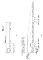
図8及び図9は、PDSCH−UL ACK/NACKタイミングを示す。ここで、UL ACK/NACKは、DLデータ(例えば、PDSCH)に対する応答であって、上りリンクで伝送されるACK/NACKを意味する。 8 and 9 show PDSCH-UL ACK / NACK timing. Here, UL ACK / NACK means a response to DL data (for example, PDSCH) and means ACK / NACK transmitted on the uplink.
図8を参照すると、端末は、M個のDLサブフレーム(SubFrame、SF)上で1つ又は複数のPDSCH信号を受信する(S502_0〜S502_M−1)。それぞれのPDSCH信号は、伝送モードに応じて1つ又は複数(例えば、2つ)の伝送ブロック(TB)の伝送に使用される。また、図示していないが、ステップS502_0〜S502_M−1でSPS解放(解除)(Semi-Persistent Scheduling release)を指示するPDCCH信号も受信される。M個のDLサブフレームにPDSCH信号及び/又はSPS解放PDCCH信号が存在すると、端末は、ACK/NACKを伝送するための過程(例えば、ACK/NACK(ペイロード)生成、ACK/NACKリソース割当など)を経て、M個のDLサブフレームに対応する1つのULサブフレームでACK/NACKを伝送する(S504)。ACK/NACKは、ステップS502_0〜S502_M−1のPDSCH信号及び/又はSPS解放PDCCH信号に関する受信応答情報を含む。ACK/NACKは、基本的にPUCCHを介して伝送されるが、ACK/NACK伝送時点にPUSCH伝送がある場合、ACK/NACKは、PUSCHを介して伝送される。ACK/NACK伝送のために、表3の様々なPUCCHフォーマットを用いることができる。また、PUCCHフォーマットで伝送されるACK/NACKのビット数を減らすために、ACK/NACKバンドリング(bundling)、ACK/NACKチャネル選択(channel selection)などの様々な方法を用いることができる。 Referring to FIG. 8, the terminal receives one or more PDSCH signals on M DL subframes (SubFrame, SF) (S502_0 to S502_M-1). Each PDSCH signal is used for transmission of one or more (eg, two) transmission blocks (TB) depending on the transmission mode. Further, although not shown, a PDCCH signal instructing SPS release (Semi-Persistent Scheduling release) is also received in steps S502_0 to S502_M-1. When a PDSCH signal and / or an SPS release PDCCH signal is present in M DL subframes, the terminal is in the process of transmitting an ACK / NACK (for example, ACK / NACK (loadage) generation, ACK / NACK resource allocation, etc.). ACK / NACK is transmitted in one UL subframe corresponding to M DL subframes (S504). ACK / NACK includes receive response information regarding the PDSCH signal and / or the SPS release PDCCH signal of steps S502_0 to S502_M-1. ACK / NACK is basically transmitted via PUCCH, but if there is PUSCH transmission at the time of ACK / NACK transmission, ACK / NACK is transmitted via PUSCH. Various PUCCH formats in Table 3 can be used for ACK / NACK transmission. Further, in order to reduce the number of ACK / NACK bits transmitted in the PUCCH format, various methods such as ACK / NACK bundling and ACK / NACK channel selection can be used.
上述したように、TDDでは、M個のDLサブフレームで受信したデータに対するACK/NACKが1つのULサブフレームで伝送され(即ち、M DL SF(s):1 UL SF)、これらの関係は、DASI(Downlink Association Set Index)によって与えられる。 As mentioned above, in TDD, ACK / NACK for data received in M DL subframes is transmitted in one UL subframe (ie, M DL SF (s): 1 UL SF), and these relationships are , Given by DASI (Downlink Association Set Index).
表4は、LTE(−A)で定義されたDASI(K:{k0,k1,...,kM-1})を示す。表4は、ACK/NACKを伝送するULサブフレームの立場で、自体と関連するDLサブフレームとの間隔を示す。具体的には、サブフレームn−k(k∈K)にPDSCH伝送及び/又はSPS解放(Semi-Persistent Scheduling release)を指示するPDCCHがある場合、端末は、サブフレームnでACK/NACKを伝送する。 Table 4 shows the DASI (K: {k 0 , k 1 , ..., k M-1 }) defined in LTE (-A). Table 4 shows the distance between itself and the associated DL subframe from the standpoint of the UL subframe that transmits ACK / NACK. Specifically, if the subframe n−k (k ∈ K) has a PDCCH instructing PDSCH transmission and / or SPS release (Semi-Persistent Scheduling release), the terminal transmits ACK / NACK in the subframe n. do.
<表4>
図9は、UL−DL構成#1が設定された場合のUL ACK/NACK伝送タイミングを例示する。同図で、SF#0〜#9及びSF#10〜#19は、それぞれ無線フレームに対応する。同図で、ボックス内の数字は、DLサブフレームの観点で自体と関連するULサブフレームを示す。例えば、SF#5のPDSCHに対するACK/NACKは、SF#5+7(=SF#12)で伝送され、SF#6のPDSCHに対するACK/NACKはSF#6+6(=SF#12)で伝送される。したがって、SF#5/SF#6の下りリンク信号に対するACK/NACKは、いずれもSF#12で伝送される。同様に、SF#14のPDSCHに対するACK/NACKは、SF#14+4(=SF#18)で伝送される。
FIG. 9 illustrates the UL ACK / NACK transmission timing when the UL-
図10及び図11は、PHICH/ULグラント(UL grant、UG)−PUSCHタイミングを示す。PUSCHは、PDCCH(ULグラント)及び/又はPHICH(NACK)に対応して伝送できる。 10 and 11 show PHICH / UL grant (UL grant, UG) -PUSCH timing. PUSCH can be transmitted in correspondence with PDCCH (UL Grant) and / or PHICH (NACK).
図10を参照すると、端末は、PDCCH(ULグラント)及び/又はPHICH(NACK)を受信する(S702)。ここで、NACKは、以前のPUSCH伝送に対するACK/NACK応答に該当する。この場合、端末は、PUSCH伝送のための過程(例えば、TB符号化、TB−CWスワップ、PUSCHリソース割当など)を経て、k個のサブフレームの後にPUSCHを介して1つ又は複数の伝送ブロック(TB)を初/再伝送する(S704)。本例は、PUSCHが一回伝送される普通(normal)のHARQ動作を仮定する。この場合、PUSCH伝送に対応するPHICH/ULグラントは、同一のサブフレームに存在する。但し、PUSCHが複数のサブフレームにより複数回伝送されるサブフレームバンドリングの場合、PUSCH伝送に対応するPHICH/ULグラントは、互いに異なるサブフレームに存在することができる。 Referring to FIG. 10, the terminal receives PDCCH (UL grant) and / or PHICH (NACK) (S702). Here, NACK corresponds to the ACK / NACK response to the previous PUSCH transmission. In this case, the terminal goes through a process for PUSCH transmission (eg, TB coding, TB-CW swap, PUSCH resource allocation, etc.), and after k subframes, one or more transmission blocks via PUSCH. (TB) is first / retransmitted (S704). This example assumes a normal HARQ operation in which the PUSCH is transmitted once. In this case, the PHICH / UL grant corresponding to PUSCH transmission exists in the same subframe. However, in the case of subframe bundling in which the PUSCH is transmitted a plurality of times by a plurality of subframes, the PHICH / UL grants corresponding to the PUSCH transmission can exist in different subframes.
表5は、LTE(−A)におけるPUSCH伝送のためのUAI(Uplink Association Index)(k)を示す。表5は、PHICH/ULグラントが検出されたDLサブフレームの立場で、自体と関連するULサブフレームとの間隔を示す。具体的には、サブフレームnでPHICH/ULグラントが検出されると、端末は、サブフレームn+kでPUSCHを伝送することができる。 Table 5 shows the UAI (Uplink Association Index) (k) for PUSCH transmission in LTE (-A). Table 5 shows the distance between itself and the associated UL subframe from the standpoint of the DL subframe in which the PHICH / UL grant was detected. Specifically, when PHICH / UL grant is detected in the subframe n, the terminal can transmit the PUSCH in the subframe n + k.
<表5>
図11は、UL−DL構成#1が設定された場合のPUSCH伝送タイミングを例示する。同図で、SF#0〜#9及びSF#10〜#19は、それぞれ無線フレームに対応する。同図で、ボックス内の数字は、DLサブフレームの観点で自体と関連するULサブフレームを示す。例えば、SF#6のPHICH/ULグラントに対するPUSCHは、SF#6+6(=SF#12)で伝送され、SF#14のPHICH/ULグラントに対するPUSCHは、SF#14+4(=SF#18)で伝送される。
FIG. 11 illustrates the PUSCH transmission timing when the UL-
図12及び図13は、PUSCH−PHICH/ULグラントタイミングを示す。PHICHは、DL ACK/NACKを伝送するときに使用される。ここで、DL ACK/NACKは、ULデータ(例えば、PUSCH)に対する応答であって、下りリンクで伝送されるACK/NACKを意味する。 12 and 13 show PUSCH-PHICH / UL grant timing. PHICH is used when transmitting DL ACK / NACK. Here, DL ACK / NACK means a response to UL data (for example, PUSCH) and means ACK / NACK transmitted on the downlink.
図12を参照すると、端末は、基地局にPUSCH信号を伝送する(S902)。ここで、PUSCH信号は、伝送モードに応じて1つ又は複数(例えば、2つ)の伝送ブロック(TB)の伝送に使用される。PUSCH伝送に対する応答として、基地局は、ACK/NACKを伝送するための過程(例えば、ACK/NACK生成、ACK/NACKリソース割当など)を経て、k個のサブフレームの後にPHICHを介してACK/NACKを端末に伝送する(S904)。ACK/NACKは、ステップS902のPUSCH信号に関する受信応答情報を含む。また、PUSCH伝送に対する応答がNACKである場合、基地局は、k個のサブフレームの後にPUSCHの再伝送のためのULグラントPDCCHを端末に伝送する(S904)。本例は、PUSCHが一回伝送される普通のHARQ動作を仮定する。この場合、PUSCH伝送に対応するPHICH/ULグラントは、同一のサブフレームで伝送されることができる。但し、サブフレームバンドリングの場合、PUSCH伝送に対応するPHICH/ULグラントは、互いに異なるサブフレームで伝送されることができる。 Referring to FIG. 12, the terminal transmits a PUSCH signal to the base station (S902). Here, the PUSCH signal is used for transmission of one or more (for example, two) transmission blocks (TB) depending on the transmission mode. In response to PUSCH transmission, the base station goes through a process for transmitting ACK / NACK (eg, ACK / NACK generation, ACK / NACK resource allocation, etc.), and after k subframes, ACK / via PHICH. The NACK is transmitted to the terminal (S904). ACK / NACK includes reception response information regarding the PUSCH signal in step S902. Further, when the response to the PUSCH transmission is NACK, the base station transmits the UL grant PDCCH for re-transmission of the PUSCH to the terminal after k subframes (S904). This example assumes a normal HARQ operation in which the PUSCH is transmitted once. In this case, the PHICH / UL grant corresponding to PUSCH transmission can be transmitted in the same subframe. However, in the case of subframe bundling, PHICH / UL grants corresponding to PUSCH transmission can be transmitted in different subframes from each other.
表6は、LTE(−A)におけるPHICH/ULグラント伝送のためのUAI(Uplink Association Index)(k)を示す。表6は、PHICH/ULグラントが存在するDLサブフレームの立場で、自体と関連するULサブフレームとの間隔を示す。具体的には、サブフレームiのPHICH/ULグラントは、サブフレームi−kのPUSCH伝送に対応する。 Table 6 shows the UAI (Uplink Association Index) (k) for PHICH / UL grant transmission in LTE (-A). Table 6 shows the distance between itself and the related UL subframe from the standpoint of the DL subframe in which the PHICH / UL grant exists. Specifically, the PHICH / UL grant of the subframe i corresponds to the PUSCH transmission of the subframe i-k.
<表6>
図13は、UL−DL構成#1が設定された場合のPHICH/ULグラント伝送タイミングを例示する。同図で、SF#0〜#9及びSF#10〜#19は、それぞれ無線フレームに対応する。同図で、ボックス内の数字は、ULサブフレームの観点で自体と関連するDLサブフレームを示す。例えば、SF#2のPUSCHに対するPHICH/ULグラントは、SF#2+4(=SF#6)で伝送され、SF#8のPUSCHに対するPHICH/ULグラントは、SF#8+6(=SF#14)で伝送される。
FIG. 13 illustrates the PHICH / UL grant transmission timing when UL-
次に、PHICHリソース割当について説明する。サブフレーム#nでPUSCH伝送があると、端末は、サブフレーム#(n+kPHICH)で対応するPCHIHリソースを決定する。FDDにおいて、kPHICHは、固定された値(例えば、4)を有する。TDDにおいて、kPHICHは、UL−DL構成に応じて異なる値を有する。表7は、TDDのためのkPHICH値を示し、表6と等価である。 Next, PHICH resource allocation will be described. When there is PUSCH transmission in subframe # n, the terminal determines the corresponding PCHIH resource in subframe # (n + k PHICH). In FDD, k PHICH has a fixed value (eg, 4). In TDD, k PHICH has different values depending on the UL-DL configuration. Table 7 shows the k PHICH values for TDD and is equivalent to Table 6.
<表7>
PHICHリソースは、[PHICHグループインデックス、直交シーケンスインデックス]によって与えられる。PHICHグループインデックス及び直交シーケンスインデックスは、(i)PUSCH伝送に用いられる最小PRBインデックスと、(ii)DMRS(DeModulation Reference Signal)サイクリックシフトのための3ビットフィールドの値を用いて決定される。(i)、(ii)は、ULグラントPDCCHにより指示される。 PHICH resources are provided by [PHICH Group Index, Orthogonal Sequence Index]. The PHICH group index and the orthogonal sequence index are determined using (i) the minimum PRB index used for PUSCH transmission and (ii) the value of a 3-bit field for DMRS (DeModulation Reference Signal) cyclic shift. (I) and (ii) are indicated by UL Grant PDCCH.
次に、HARQプロセスについて説明する。端末には、UL伝送のために複数の並列HARQプロセスが存在する。複数の並列HARQプロセスは、以前のUL伝送に対する成功又は失敗の受信に対するHARQフィードバックを待つ間に、UL伝送が連続して行われるようにする。それぞれのHARQプロセスは、MAC(Medium Access Control)層のHARQバッファと関連する。それぞれのHARQプロセスは、バッファ内のMAC PDU(Physical Data Block)の伝送回数、バッファ内のMAC PDUに対するHARQフィードバック、現在の冗長(リダンダンシ)バージョン(redundancy version)などに関する状態変数を管理する。 Next, the HARQ process will be described. There are multiple parallel HARQ processes at the terminal for UL transmission. Multiple parallel HARQ processes ensure that UL transmissions occur in succession while waiting for HARQ feedback for successful or unsuccessful reception of previous UL transmissions. Each HARQ process is associated with a MAC (Medium Access Control) layer HARQ buffer. Each HARQ process manages state variables related to the number of transmissions of the MAC PDU (Physical Data Block) in the buffer, HARQ feedback to the MAC PDU in the buffer, the current redundancy version, and the like.
LTE(−A)FDDの場合、ノンサブフレームバンドリング動作(即ち、普通のHARQ動作)のためのUL HARQプロセスの数は、8個である。一方、LTE(−A) TDDの場合には、UL−DL構成に応じてULサブフレームの個数が異なるので、UL HARQプロセスの数及びHARQ RTT(Round Trip Time)もUL−DL構成ごとに異なる。ここで、HARQ RTTは、ULグラントを受信した時点から(これに対応する)PUSCH伝送を経て、(これに対応する)PHICHが受信される時点までの時間間隔(例えば、SF若しくはms単位)、又はPUSCH伝送時点からこれに対応する再伝送時点までの時間間隔を意味する。 For LTE (-A) FDD, the number of UL HARQ processes for non-subframe bundling operations (ie, normal HARQ operations) is eight. On the other hand, in the case of LTE (-A) TDD, since the number of UL subframes differs depending on the UL-DL configuration, the number of UL HARQ processes and the HARQ RTT (Round Trip Time) also differ depending on the UL-DL configuration. .. Here, the HARQ RTT is a time interval (for example, SF or ms unit) from the time when the UL grant is received to the time when the PHICH (corresponding to this) is received via the PUSCH transmission (corresponding to this). Alternatively, it means the time interval from the PUSCH transmission time point to the corresponding retransmission time point.
UL HARQプロセスの数は、変わる。サブフレームバンドリングが適用されると、FDD及びTDDにおいて、4個の連続するULサブフレームで構成された1つのバンドル(一束)の(a bundle of)PUSCH伝送が行われる。したがって、サブフレームバンドリングが適用される場合のHARQ動作/プロセスは、上述した普通のHARQ動作/プロセスとは異なる。 The number of UL HARQ processes varies. When subframe bundling is applied, a bundle of PUSCH transmission in FDD and TDD is performed, consisting of four consecutive UL subframes. Therefore, the HARQ operation / process when subframe bundling is applied is different from the normal HARQ operation / process described above.
表8は、TDDにおける同期式UL HARQプロセスの数及びHARQ RTTを示す。UL HARQ RTTが10[SFs又はms]である場合(UL−DL構成#1、#2、#3、#4、#5)、1つのUL HARQプロセスは、1つの固定したUL SFタイミングを使用する。反面、UL HARQ RTTが10[SFs又はms]ではない場合(UL−DL構成#0、#6)、1つのUL HARQプロセスは、(1つの固定したUL SFタイミングではなく)複数のUL SFタイミングを(ホッピングしながら)使用する。例えば、UL−DL構成#6の場合、1つのUL HARQプロセスにおいて、PUSCH伝送タイミングは、次の通りである。SF#2:PUSCH⇒SF#13:PUSCH(RTT:11SFs)⇒SF#24:PUSCH(RTT:11SFs)⇒SF#37:PUSCH(RTT:13SFs)⇒SF#48:PUSCH(RTT:11SFs)⇒SF#52:PUSCH(RTT:14SFs)。
Table 8 shows the number of synchronous UL HARQ processes in TDD and the HARQ RTT. If the UL HARQ RTT is 10 [SFs or ms] (UL-
<表8>
TDD UL−DL構成が#1〜6であり、普通のHARQ動作時、ULグラントPDCCH及び/又はPHICHがサブフレームnで検出されると、端末は、PDCCH及び/又はPHICH情報によって、サブフレームn+k(表5参照)で対応するPUSCH信号を伝送する。 When the TDD UL-DL configuration is # 1 to 6 and UL grant PDCCH and / or PHICH is detected in subframe n during normal HARQ operation, the terminal uses PDCCH and / or PHICH information to detect subframe n + k. The corresponding PUSCH signal is transmitted in (see Table 5).
TDD UL−DL構成が#0であり、普通のHARQ動作時、UL DCIグラントPDCCH及び/又はPHICHがサブフレームnで検出される場合、端末のPUSCH伝送タイミングは、条件によって変わる。まず、DCI内のULインデックスのMSB(Most Significant Bit)が1であるか、又はPHICHがサブフレーム#0若しくは#5でIPHICH=0に対応するリソースで受信された場合、端末は、サブフレームn+k(表5参照)で対応するPUSCH信号を伝送する。次に、DCI内のULインデックスのLSB(Least Significant Bit)が1であるか、PHICHがサブフレーム#0若しくは#5でIPHICH=1に対応するリソースで受信されるか、又はPHICHがサブフレーム#1若しくは#6で受信された場合、端末は、サブフレームn+7で対応するPUSCH信号を伝送する。次に、DCI内のMSB及びLSBが全てセットされた場合、端末は、サブフレームn+k(表5参照)及びサブフレームn+7で対応するPUSCH信号を伝送する。
When the TDD UL-DL configuration is # 0 and UL DCI grant PDCCH and / or PHICH is detected in subframe n during normal HARQ operation, the PUSCH transmission timing of the terminal changes depending on the conditions. First, when the MSB (Most Significant Bit) of the UL index in DCI is 1, or PHICH is received in
図14は、UL−DL構成#1が設定された場合の同期式UL HARQプロセスを例示する。ボックス内の数字は、UL HARQプロセス番号を例示する。本例は、普通(normal)のUL HARQプロセスを示す。図14を参照すると、HARQプロセス#1は、SF#2、SF#6、SF#12、SF#16に関与する。例えば、初期PUSCH信号(例えば、RV=0)がSF#2で伝送された場合、対応するULグラントPDCCH及び/又はPHICHは、SF#6で受信され、対応する(再伝送)PUSCH信号(例えば、RV=2)がSF#12で伝送されることができる。したがって、UL−DL構成#1の場合、RTT(Round Trip Time)が10SFs(又は10ms)である4個のUL HARQプロセスが存在する。
FIG. 14 illustrates a synchronous UL HARQ process when UL-
図15は、キャリアアグリゲーション(併合)(Carrier Aggregation、CA)通信システムを例示する。 FIG. 15 illustrates a Carrier Aggregation (CA) communication system.
図15を参照すると、複数のUL/DLコンポーネントキャリア(Component Carrier、CC)は、より広いUL/DL帯域幅をサポートすることができる。CCは、周波数領域で互いに連続(隣接)しても(contiguous)しなくてもよい。各CCの帯域幅は、独立して決定できる。UL CCの数とDL CCの数とが異なる非対称キャリアのアグリゲーションも可能である。なお、制御情報は、特定のCCを通じてのみ送受信できるように設定される。この特定のCCをプライマリCCと称し、その他のCCをセカンダリCCと称する。一例として、クロスキャリアスケジューリング(cross-carrier scheduling)(又はクロスCCスケジューリング)が適用される場合、下りリンク割り当てのためのPDCCHは、DL CC#0で伝送され、該当PDSCHは、DL CC#2で伝送される。用語‘コンポーネントキャリア’は、等価の他の用語(例えば、キャリア、セルなど)に代替できる。
Referring to FIG. 15, a plurality of UL / DL component carriers (CC) can support a wider UL / DL bandwidth. The CCs may or may not be contiguous with each other in the frequency domain. The bandwidth of each CC can be determined independently. Aggregation of asymmetric carriers with different numbers of UL CCs and DL CCs is also possible. The control information is set so that it can be transmitted and received only through a specific CC. This specific CC is referred to as the primary CC, and the other CCs are referred to as the secondary CC. As an example, when cross-carrier scheduling (or cross-CC scheduling) is applied, the PDCCH for downlink allocation is transmitted on
クロスCCスケジューリングのために、CIF(Carrier Indicator Field)が使用される。PDCCH内にCIFの存在又は不在に関連する設定が、準静的(半−静的)に(semi-statically)端末固有(又は端末グループ固有)に上位層シグナリング(例えば、RRCシグナリング)によって可能になる(enable)。以下、PDCCH伝送の基本事項を整理する。 CIF (Carrier Indicator Field) is used for cross-CC scheduling. Settings related to the presence or absence of CIF in the PDCCH can be quasi-statically (semi-statically) terminal-specific (or terminal group-specific) by higher-layer signaling (eg, RRC signaling). Become (enable). The basic items of PDCCH transmission are summarized below.
■ CIFディセーブルド(disabled):DL CC上のPDCCHは、同じDL CC上のPDSCHリソース及び単一のリンクされたUL CC上のPUSCHリソースを割り当てる。 ■ CIF disabled: PDCCH on the DL CC allocates PDSCH resources on the same DL CC and PUSCH resources on a single linked UL CC.
● No CIF ● No CIF
■ CIFイネーブルド(enabled):DL CC上のPDCCHは、CIFを用いて複数の統合されたDL/UL CCのうちの特定のDL/UL CC上のPDSCH又はPUSCHリソースを割り当てることができる。 ■ CIF enabled: A PDCCH on a DL CC can use the CIF to allocate a PDSCH or PUSCH resource on a particular DL / UL CC out of a plurality of integrated DL / UL CCs.
● CIFを有するように拡張されたLTE DCIフォーマット ● LTE DCI format extended to have CIF
− CIF(設定された場合)は、固定されたxビットフィールド(例えば、X=3) -CIF (if set) is a fixed x-bit field (eg X = 3)
− CIF(設定された場合)の位置は、DCIフォーマットサイズに関係なく固定される。 -The position of the CIF (if set) is fixed regardless of the DCI format size.
CIFが存在するとき、基地局は、端末側のBDの複雑度を低くするために、モニタリングDL CC(セット)を割り当てることができる。PDSCH/PUSCHスケジューリングのために、端末は、該当DL CCでのみPDCCHの検出/復号を行う。また、基地局は、モニタリングDL CC(セット)を通じてのみPDCCHを伝送できる。モニタリングDL CCセットは、端末固有、端末グループ固有又はセル固有の方式でセットされる。 When a CIF is present, the base station can assign a monitoring DL CC (set) to reduce the complexity of the terminal-side BD. For PDSCH / PUSCH scheduling, the terminal detects / decodes PDCCH only in the corresponding DL CC. Also, the base station can transmit PDCCH only through the monitoring DL CC (set). The monitoring DL CC set is set in a terminal-specific, terminal group-specific, or cell-specific manner.
図16は、複数のキャリアが統合された場合のスケジューリングを例示する。3個のDL CCが統合され、DL CCAがPDCCHモニタリングDL CCに設定された場合を例示する。DL CCA〜Cは、サービングCC、サービングキャリア、サービングセルなどと言える。CIFがディセーブルされた場合、それぞれのDL CCは、LTE PDCCHの規則に従って、CIFなしで自体のPDSCHをスケジューリングするPDCCHのみを送信することができる(非クロスCCスケジューリング)。反面、端末固有(又は端末グループ固有又はセル固有)の上位層シグナリングによってCIFが可能になると、特定のCC(例えば、DL CC A)は、CIFを用いてDL CC AのPDSCHをスケジューリングするPDCCHだけではなく、他のCCのPDSCHをスケジューリングするPDCCHも伝送できる(クロスCCスケジューリング)。反面、DL CC B/Cでは、PDCCHは伝送されない。 FIG. 16 illustrates scheduling when a plurality of carriers are integrated. The case where three DL CCs are integrated and the DL CCA is set as the PDCCH monitoring DL CC is illustrated. DL CCA to C can be said to be a serving CC, a serving carrier, a serving cell, and the like. When CIF is disabled, each DL CC can only send PDCCH that schedules its own PDSCH without CIF according to the rules of LTE PDCCH (non-cross CC scheduling). On the other hand, when CIF is enabled by terminal-specific (or terminal group-specific or cell-specific) upper layer signaling, the only specific CC (eg, DL CC A) is the PDC CH that schedules the DL CC A PDSCH using the CIF. Instead, PDCCH that schedules PDSCH of other CCs can also be transmitted (cross CC scheduling). On the other hand, in DL CC B / C, PDCCH is not transmitted.
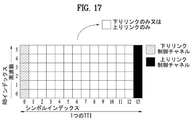
一方、次世代RAT(Radio Access Technology)においては、データ伝送遅延(latency)を最小にするために、セルフコンテインド(self-contained)サブフレームが考えられている。図17は、セルフコンテインドサブフレームの構造を例示している。図17において、斜線領域は、DL制御領域を示し、黒色部分は、UL制御領域を示す。その他の領域は、DLデータ伝送又はULデータ伝送のために使用される。1つのサブフレーム内でDL伝送とUL伝送とが順に行われるので、該サブフレーム内でDLデータを送り出し、UL ACK/NACKを受け取ることができる。結果として、データ伝送エラーの発生時にデータ再伝送までにかかる時間を短縮させることにより、最終データ伝達の遅延を最小にすることができる。 On the other hand, in the next-generation RAT (Radio Access Technology), a self-contained subframe is considered in order to minimize the data transmission delay (latency). FIG. 17 illustrates the structure of a self-contained subframe. In FIG. 17, the shaded area indicates the DL control area, and the black part indicates the UL control area. Other areas are used for DL data transmission or UL data transmission. Since DL transmission and UL transmission are performed in order in one subframe, DL data can be sent out and UL ACK / NACK can be received in the subframe. As a result, the delay in final data transmission can be minimized by reducing the time required for data re-transmission when a data transmission error occurs.
構成/設定が可能なセルフコンテインドサブフレームタイプの例として、少なくとも以下の4つのタイプが考えられる。各々の区間は、時間順に並んでいる。 At least the following four types can be considered as examples of self-contained subframe types that can be configured / set. Each section is arranged in chronological order.
−DL制御区間+DLデータ区間+GP(Guard Period)+UL制御区間 -DL control section + DL data section + GP (Guard Period) + UL control section
−DL制御区間+DLデータ区間 -DL control interval + DL data interval
−DL制御区間+GP+ULデータ区間+UL制御区間 -DL control section + GP + UL data section + UL control section
−DL制御区間+GP+ULデータ区間 -DL control section + GP + UL data section
DL制御区間では、PDFICH、PHICH、PDCCHが伝送され、DLデータ区間では、PDSCHが伝送される。UL制御区間では、PUCCHが伝送され、ULデータ区間では、PUSCHが伝送される。GPは、基地局及び端末が、送信モードから受信モードに転換される(切り替えられる)過程又は受信モードから送信モードに転換される過程で時間ギャップを提供する。サブフレーム内においてDLからULに転換される時点の一部のOFDMシンボルがGPとして設定される。 In the DL control section, PDFICH, PHICH, and PDCCH are transmitted, and in the DL data section, PDSCH is transmitted. PUCCH is transmitted in the UL control section, and PUSCH is transmitted in the UL data section. The GP provides a time gap in the process in which the base station and the terminal are converted (switched) from the transmission mode to the reception mode or from the reception mode to the transmission mode. Some OFDM symbols at the time of conversion from DL to UL in the subframe are set as GP.
実施例Example
new RATシステムは、eMBB(enhanced Mobile Broadband)、URLLC(Ultra-Reliable and Low Latency Communications)、mMTC(massive Machine type Communications)などの様々な使用シナリオ(又はサービスタイプ、トラフィックタイプ)をサポートするように設計できるが、様々な使用シナリオ(以下、使用例)は、特に(ユーザプレーン(平面))遅延の側面で各々異なる要件(requirement)を有することができる。一例として、各使用例で要求される(最大の)遅延は、URLLC(例えば、0.5ms)<eMBB(例えば、4ms)<mMTC(例えば、X ms>4ms)の順に異なるように与えられる。これにより、TTI長も使用例ごとに異なるように設定できる。例えば、TTI長が、URLLC<eMBB<mMTCの順に異なるように与えられることができる。ここで、TTIは、データスケジューリング間の(最小の)時間間隔又は単一データの(最大の)送信時間区間(duration)として定義されることができる。データスケジューリング間の(最小の)時間間隔又は単一データの(最大の)送信時間区間は、サブフレーム(SF)又はスロットの整数/実数倍で表現されるか、又はOFDMシンボルの整数倍で表現される。
The new RAT system is designed to support various usage scenarios (or service types, traffic types) such as eMBB (enhanced Mobile Broadband), URLLC (Ultra-Reliable and Low Latency Communications), and mMTC (massive Machine type Communications). Although it is possible, various usage scenarios (hereinafter referred to as usage examples) can have different requirements, especially in terms of delay (user plane). As an example, the (maximum) delay required in each use case is given differently in the order URLLC (eg 0.5 ms) <eMBB (
一方、DL/ULデータのスケジューリング/送信のためのHARQタイミングの設定及びHARQプロセスの運用は、遅延要件/TTI長(これによる使用例)、DL/UL信号処理(例えば、DL制御/データチャネルの復号、符号化を含むUL送信準備など)に関連する端末能力などによって変わる。例えば、(最小の)HARQタイミングの遅延は、URLLCがeMBBより小さく設定される反面、(最大の)HARQプロセス数は、eMBBがURLLCより大きく設定される。ここで、HARQタイミングは、DLデータの受信とHARQ−ACKの送信との間の遅延、ULグラントの受信とULデータの送信との間の遅延などを示し、TTIの整数倍で表現される。 On the other hand, the setting of HARQ timing for scheduling / transmitting DL / UL data and the operation of the HARQ process include delay requirements / TTI length (use example), DL / UL signal processing (for example, DL control / data channel). It depends on the terminal ability related to decryption, preparation for UL transmission including coding, etc.). For example, the (minimum) HARQ timing delay sets the URLLC to be smaller than the eMBB, while the (maximum) number of HARQ processes sets the eMBB to be larger than the URLLC. Here, the HARQ timing indicates a delay between the reception of DL data and the transmission of HARQ-ACK, a delay between the reception of UL grant and the transmission of UL data, and is expressed as an integral multiple of TTI.
以下、異なる遅延が要求される使用例(又はそれに対応する異なるTTI長)を考慮した効果的なDL/UL HARQタイミングの設定及びHARQプロセスの運用方法を提案する。本発明において、(i)TTIとSFとは、時間の長さ又は時間区間の観点で同じ意味で使用される(例えば、SFオフセットは、TTIオフセットと考慮されることができる)か、(ii)TTI長は、各使用例ごとに異なる値に設定され、SFの長さ(SF長)は、全ての使用例について共通した単一値に設定されることができる(例えば、SFは、可能な複数のTTI長のうち、特定の1つの同一の時間区間を有することができる)。(ii)の場合、(ii−1)SFは、最小TTI(例えば、URLLCに設定されるTTI長)と同じ時間区間を有するように設定されるか、(ii−2)SFは、ノーマル(一般)(normal)TTIと同じ時間区間(例えば、eMBBに設定されるTTI長)を有するように設定されることができる。(ii−1)の場合、特定の使用例で設定される1つのTTIは、1つ又は複数のSF(或いはスロット)で構成され、(ii−2)の場合、特定の使用例で設定される1つのTTIは、1つ又は複数のSF(或いはスロット)で構成されるか、又は複数のTTIが、1つのSF(或いはスロット)内に構成されることができる。 Hereinafter, we propose an effective DL / UL HARQ timing setting and an operation method of the HARQ process in consideration of usage examples (or corresponding different TTI lengths) that require different delays. In the present invention, (i) TTI and SF are used interchangeably in terms of time length or time interval (for example, SF offset can be considered as TTI offset) or (ii). The TTI length can be set to a different value for each use case, and the SF length (SF length) can be set to a single value common to all use cases (for example, SF is possible). Can have one particular time interval of multiple TTI lengths). In the case of (ii), the (ii-1) SF is set to have the same time interval as the minimum TTI (eg, the TTI length set in the URLLC), or the (ii-2) SF is normal (ii-2). It can be set to have the same time interval as the (normal) TTI (eg, the TTI length set in the eMBB). In the case of (ii-1), one TTI set in a specific usage example is composed of one or a plurality of SFs (or slots), and in the case of (ii-2), it is set in a specific usage example. One TTI can be composed of one or more SFs (or slots), or a plurality of TTIs can be composed of one SF (or slot).
説明の便宜上、端末及び基地局で要求される各(最小)HARQタイミングの遅延を定義すると、以下の通りである。 For convenience of explanation, the delay of each (minimum) HARQ timing required by the terminal and the base station is defined as follows.
1)dUE_DL:DLデータの受信とHARQ−ACKの送信との間における遅延(端末において)。端末は、自体のdUE_DL情報(能力)を適切な時点(例えば、初期アクセス或いはRRC接続(連結)(RRC connection)過程)で基地局に報告することができる。同じ端末に対して、dUE_DL情報と以下のdUE_UL情報とが異なるようにサポートされることができる。 1) dUE_DL: Delay (at the terminal) between the reception of DL data and the transmission of HARQ-ACK. The terminal can report its dUE_DL information (capacity) to the base station at an appropriate time point (eg, initial access or RRC connection process). For the same terminal, the dUE_DL information and the following dUE_UL information can be supported differently.
2)dNB_DL:HARQ−ACK受信とDLデータの再送信との間における遅延(基地局において)。基地局は、dNB_DL情報を適切な時点で端末にシグナリングすることができる。dNB_DL情報は、以下のdNB_UL情報と異なるように設定される。あるいは、基地局が以下のRTT_DL又はHARQ_DL情報を適切な時点で端末にシグナリングし、端末は、該当RTT_DL又はHARQ_DL情報からdNB_DL情報を算出することができる。 2) dNB_DL: Delay between HARQ-ACK reception and DL data retransmission (at the base station). The base station can signal the dNB_DL information to the terminal at an appropriate time. The dNB_DL information is set to be different from the following dNB_UL information. Alternatively, the base station signals the following RTT_DL or HARQ_DL information to the terminal at an appropriate time, and the terminal can calculate the dNB_DL information from the corresponding RTT_DL or HARQ_DL information.
3)RTT_DL:同じHARQプロセスのDLデータ送信間の(最小の)遅延(例えば、dUE_DL+dNB_DL) 3) RTT_DL: (minimum) delay between DL data transmissions of the same HARQ process (eg dUE_DL + dNB_DL)
4)HARQ_DL:(最大の)DL HARQプロセス数(例えば、RTT_DL内におけるTTIの最大数)。HARQ_DL値によって、DLグラントDCI内でHARQプロセスIDを指定するビット数、並びに/又はDLソフトバッファの観点で各々のDLデータ(例えば、TB)若しくはHARQプロセス当たり記憶する最初のビット数が異なるように決定される。 4) HARQ_DL: (maximum) DL HARQ process number (eg, maximum number of TTIs in RTT_DL). Depending on the HARQ_DL value, the number of bits that specify the HARQ process ID in the DL grant DCI and / or the first number of bits to be stored per DL data (eg, TB) or HARQ process in terms of the DL soft buffer is different. It is determined.
5)dUE_UL:(端末における)ULグラントの受信とULデータの送信との間の遅延。端末は、自体のdUE_UL情報(能力)を適切な時点(例えば、初期アクセス或いはRRC接続過程)で基地局に報告することができる。同じ端末に対して、dUE_UL情報とdUE_DL情報とが異なるようにサポートされることができる。 5) dUE_UL: The delay between the reception of the UL grant (at the terminal) and the transmission of the UL data. The terminal can report its dUE_UL information (capacity) to the base station at an appropriate time point (for example, initial access or RRC connection process). The dUE_UL information and the dUE_DL information can be supported differently for the same terminal.
6)dNB_UL:ULデータの受信と再送信ULグラントの送信との間の遅延(基地局において)。基地局は、dNB_UL情報を適切な時点で端末にシグナリングすることができる。dNB_UL情報は、dNB_DL情報と異なるように設定される。あるいは、基地局は、以下のRTT_UL又はHARQ_UL情報を適切な時点で端末にシグナリングし、端末は、該当RTT_UL又はHARQ_UL情報からdNB_UL情報を算出することができる。 6) dNB_UL: The delay between the reception of UL data and the transmission of the retransmitted UL grant (at the base station). The base station can signal the dNB_UL information to the terminal at an appropriate time. The dNB_UL information is set to be different from the dNB_DL information. Alternatively, the base station signals the following RTT_UL or HARQ_UL information to the terminal at an appropriate time, and the terminal can calculate the dNB_UL information from the corresponding RTT_UL or HARQ_UL information.
7)RTT_UL:同じHARQプロセスのULデータ送信間の(最小の)遅延(例えば、dUE_UL+dNB_UL) 7) RTT_UL: (minimum) delay between UL data transmissions in the same HARQ process (eg dUE_UL + dNB_UL)
8)HARQ_UL:(最大の)UL HARQプロセス数(例えば、RTT_UL内におけるTTIの最大数)。HARQ_UL値によってULグラントDCI内にHARQプロセスIDを指定するビット数、並びに/又はULソフトバッファの観点で各々のULデータ(例えば、TB)若しくはHARQプロセス当たりのバッファリングする最初のビット数が異なるように決定される。 8) HARQ_UL: (maximum) number of UL HARQ processes (eg, maximum number of TTIs in RTT_UL). The number of bits that specify the HARQ process ID in the UL grant DCI and / or the number of initial buffered bits per UL data (eg TB) or HARQ process in terms of the UL soft buffer may differ depending on the HARQ_UL value. Is decided on.
図18乃至図21は、HARQタイミング遅延による信号送受信を例示する。同図を参照すると、端末は、DLデータの受信後、dUE_DL以後にHARQ−ACKを送信する。HARQ−ACKがNACKである場合、基地局は、dNB_DL以後にDLデータを再送信する。同様に、端末は、ULグラントの受信後、dUE_UL以後にULデータ(例えば、PUSCH)を送信することができる。ULデータに対して再送信が必要な場合、基地局は、dNB_UL以後にULデータの再送信を指示するULグラントを送信することができる。 18 to 21 illustrate signal transmission / reception due to HARQ timing delay. Referring to the figure, the terminal transmits HARQ-ACK after dUE_DL after receiving the DL data. If HARQ-ACK is NACK, the base station retransmits DL data after dNB_DL. Similarly, the terminal can transmit UL data (for example, PUSCH) after dUE_UL after receiving the UL grant. When the UL data needs to be retransmitted, the base station can transmit a UL grant instructing the retransmission of the UL data after dNB_UL.
本発明において、TTI長、使用例及びOFDMの変復調に使用される副搬送波(SC)間隔(即ち、SCS)は、互いに類似する意味で使用されるか又は代替されることができる。例えば、short TTI長は、large SCS又はURLLCのような意味を有し、long TTI長は、small SCS又はmMTCのような意味を有することができる。(short TTI長とlong TTI長との間の)ノーマルTTITTI長は、(small SCSとlarge SCSとの間の)ノーマルSCS又はeMBBのような意味を有することができる。HARQタイミング遅延は、SF/スロット/TTI長の整数倍(又は実数倍)で与えられるか、又はOFDMシンボル区間の整数倍で与えられる。ここで、OFDMシンボルとは、OFDMベースのシンボルを通称し(例えば、OFDMシンボル、SC−FDMAシンボルなど)、簡単にシンボルと表現することもできる。また、TTI長は、単一のTTIを構成するSF/スロット/シンボル数、即ち、TTI当たりのSF/スロット/シンボル数のような意味で使用されるか又は代替されることができる。例えば、long TTI長は、TTI当たりのSF/スロット/シンボル数が多い場合、short TTI長は、TTI当たりのSF/スロット/シンボル数が少ない場合のような意味になる。また、TTI/SF/スロットは、混用できる。また、この明細書において、‘長い/短い/増加する/減少する’は、相対的に長い/短い/増加する/減少することを意味するか、又は特定の基準値を基準として長い/短い/増加する/減少することを意味することができる。例えば、後者の場合、TTI長Xの場合に対してHARQタイミング遅延(又は最小のHARQ RTT)がA個のTTI区間に設定され、TTI長Yの場合に対してHARQタイミング遅延(又は最小のHARQ RTT)がB個のTTI区間に設定されると仮定したとき、(実際のTTI長に関係なく)AとBとの大小関係によって、2つのTTI長X及びYのうちのいずれかは、HARQタイミングの遅延(又は最小のHARQ RTT)がさらに長い/短い/増加する/減少すると記述されることができる。また、この明細書において、eNBとgNBとは入れ替えてもよい。また、以下に説明する方式は、互いに組み合わせることもできる。 In the present invention, the TTI length, usage examples and subcarrier (SC) spacing (ie, SCS) used for modulation / demodulation of OFDM can be used or replaced in a similar sense to each other. For example, the short TTI length can have a meaning such as large SCS or URLLC, and the long TTI length can have a meaning such as small SCS or mMTC. The normal TTITI length (between the short TTI length and the long TTI length) can have a meaning like the normal SCS or eMBB (between the small SCS and the large SCS). The HARQ timing delay is given as an integral multiple (or real multiple) of the SF / slot / TTI length, or as an integral multiple of the OFDM symbol interval. Here, the OFDM symbol is a common name for an OFDM-based symbol (for example, an OFDM symbol, an SC-FDMA symbol, etc.), and can be easily expressed as a symbol. Also, the TTI length can be used or substituted in the sense of the number of SFs / slots / symbols that make up a single TTI, i.e., the number of SFs / slots / symbols per TTI. For example, the long TTI length means that the number of SFs / slots / symbols per TTI is large, and the short TTI length means that the number of SFs / slots / symbols per TTI is small. Moreover, TTI / SF / slot can be mixed. Also, in this specification,'long / short / increase / decrease' means relatively long / short / increase / decrease, or long / short / relative to a specific reference value. It can mean increase / decrease. For example, in the latter case, HARQ timing delay (or minimum HARQ RTT) is set for A TTI intervals for TTI length X, and HARQ timing delay (or minimum HARQ) for TTI length Y. Assuming that RTT) is set to B TTI intervals, one of the two TTI lengths X and Y will be HARQ, depending on the magnitude relationship between A and B (regardless of the actual TTI length). The timing delay (or minimum HARQ RTT) can be described as being longer / shorter / increasing / decreasing. Further, in this specification, eNB and gNB may be interchanged. In addition, the methods described below can be combined with each other.
[方式1]HARQプロセス遅延及びHARQプロセス番号 [Method 1] HARQ process delay and HARQ process number
この方式では、HARQ動作のための端末(例えば、UE)及び基地局(例えば、eNB)におけるデータ処理遅延、また、それに関連するHARQプロセス数、並びに受信バッファの運用方法について提案する。以下、HARQ(処理)遅延は、UEの場合、(i)DLデータの受信時点とそれに対応するHARQ−ACKの送信時点との間の時間遅延(dUE_DL)、又は(ii)ULグラントの受信時点とそれに対応するULデータの送信時点との間の時間遅延(dUE_UL)を意味することができる。また、HARQ(処理)遅延は、eNBの場合、(i)HARQ−ACKの受信時点とそれに対応する再送信DLデータのスケジューリング(DLグラントの送信)の時点との間の時間遅延(dNB_DL)、又は(ii)ULデータの受信時点とそれに対応する再送信ULデータのスケジューリング(ULグラントの送信)の時点との間の時間遅延(dNB_UL)を意味することができる。また、(最小の)HARQ RTTは、DL(又はUL)データの送信(スケジューリング)時点とそれに対応する(該当データと同じHARQプロセスIDを有する)DL(又はUL)データの再送信(スケジューリング)の時点との間の(最小の)時間遅延(RTT_DL、RTT_UL)を意味することができる。 This method proposes a data processing delay in a terminal (for example, UE) and a base station (for example, eNB) for HARQ operation, a number of HARQ processes related thereto, and an operation method of a receive buffer. Hereinafter, in the case of a UE, the HARQ (processing) delay is a time delay (dUE_DL) between (i) a DL data reception time point and a corresponding HARQ-ACK transmission time point, or (ii) a UL grant reception time point. It can mean a time delay (dUE_UL) between and the corresponding UL data transmission time point. Further, in the case of eNB, the HARQ (processing) delay is a time delay (dNB_DL) between (i) the time point of receiving HARQ-ACK and the time point of scheduling (DL grant transmission) of the corresponding retransmission DL data. Alternatively, (ii) can mean a time delay (dNB_UL) between the time point of receiving the UL data and the corresponding time point of scheduling the retransmission UL data (transmission of the UL grant). Also, the (minimum) HARQ RTT is the time point of transmission (scheduling) of DL (or UL) data and the corresponding retransmission (scheduling) of DL (or UL) data (having the same HARQ process ID as the corresponding data). It can mean the (minimum) time delay (RTT_DL, RTT_UL) between time points.
(1)HARQプロセス遅延 (1) HARQ process delay
A.UE遅延 A. UE delay
i.Capable min UE遅延(min_dUE_cap):UEが自体のカテゴリ及び能力/具現によってサポート可能な最小のHARQ遅延 i. Capable min UE delay (min_dUE_cap): The minimum HARQ delay that a UE can support by its category and capabilities / implementation.
ii.Configured min UE遅延(min_dUE_cfg):eNBがUEに設定した候補HARQ遅延のうちの最小のHARQ遅延 ii. Configured min UE delay (min_dUE_cfg): The smallest HARQ delay of the candidate HARQ delays that the eNB has set for the UE.
iii.Configured max UE遅延(max_dUE_cfg):eNBがUEに設定した候補HARQ遅延のうちの最大のHARQ遅延。max_dUE_cfgの設定可能な最大値は、以下のdUE_デフォルトと同じ値に設定される。 iii. Configured max UE delay (max_dUE_cfg): The maximum HARQ delay of the candidate HARQ delays that the eNB has set for the UE. The maximum value that can be set for max_dUE_cfg is set to the same value as the following dUE_default.
iv.デフォルトUE遅延(dUE_デフォルト):eNBからHARQ遅延が設定される前の時点又はランダムアクセス過程でUEが仮定/適用する自体のHARQ遅延 iv. Default UE delay (dUE_default): The HARQ delay of its own that the UE assumes / applies at a point in time before the HARQ delay is set from the eNB or in the random access process.
B.eNB遅延 B. eNB delay
i.Capable min eNB遅延(min_dNB_cap):eNBが自体の具現及びセル管理(management)によってサポート可能な最小のHARQ遅延 i. Capable min eNB delay (min_dNB_cap): The minimum HARQ delay that an eNB can support through its own realization and cell management.
ii.Configured min eNB遅延(min_dNB_cfg):eNBがUEに設定するeNBで所要の最小のHARQ遅延 ii. Configured min eNB delay (min_dNB_cfg): The minimum HARQ delay required by the eNB set by the eNB in the UE.
1.UEは、特定のDL HARQプロセスIDに対するHARQ−ACKの送信時点から以後のmin_dNB_cfgだけの区間内では、該当DL HARQプロセスIDを有するDLデータ(再送信)に対するスケジューリング(これに対応するDLグラントの受信)はないと仮定した/見なした状態で動作することができる。例えば、UEは、該当DL HARQプロセスIDを有するDLデータ(再送信)に対するスケジューリング情報(例えば、DLグラント)を受信しても、該当DLデータ(再送信)に対する復号動作を省略することができる。 1. 1. The UE schedules the DL data (retransmission) having the corresponding DL HARQ process ID (reception of the corresponding DL grant) within the interval of only min_dNB_cfg after the transmission time of the HARQ-ACK for the specific DL HARQ process ID. ) Can be operated in the assumed / deemed state. For example, even if the UE receives the scheduling information (for example, DL grant) for the DL data (retransmission) having the corresponding DL HARQ process ID, the decoding operation for the corresponding DL data (retransmission) can be omitted.
2.UEは、特定のUL HARQプロセスIDを有するULデータの送信時点から以後のmin_dNB_cfgだけの区間内では、該当UL HARQプロセスIDを有するULデータ(再送信)に対するスケジューリング(これに対応するULグラントの受信)はないと仮定した/見なした状態で動作することができる。例えば、UEは、該当UL HARQプロセスIDを有するULデータ(再送信)に対するスケジューリング情報(例えば、ULグラント)を受信しても、該当ULデータ(再送信)に対する送信動作を省略することができる。 2. The UE schedules the UL data (retransmission) having the corresponding UL HARQ process ID (reception of the corresponding UL grant) within the interval of only min_dNB_cfg after the transmission time of the UL data having the specific UL HARQ process ID. ) Can be operated in the assumed / deemed state. For example, even if the UE receives the scheduling information (for example, UL grant) for the UL data (retransmission) having the corresponding UL HARQ process ID, the transmission operation for the corresponding UL data (retransmission) can be omitted.
3.min_dNB_cfgは、min UE遅延値(再設定)に関係なく1つの値に設定されることができる。他の例として、min_dNB_cfgは、別の設定なしで、min UE遅延値によって自動設定できる(例えば、min UE遅延と同じ値或いはmin UE遅延に比例する値に設定)。さらに他の例として、min_dNB_cfgは、eNBから設定されたmax HARQnum値によって自動設定できる(例えば、max HARQnumからmin UE遅延を引いた値に設定)。 3. 3. min_dNB_cfg can be set to one value regardless of the min UE delay value (reset). As another example, min_dNB_cfg can be automatically set by the min UE delay value without any other setting (for example, set to the same value as the min UE delay or a value proportional to the min UE delay). As yet another example, min_dNB_cfg can be automatically set by the max HARQnum value set from the eNB (for example, set to the value obtained by subtracting the min UE delay from max HARQnum).
4.min_dNB_cfgの設定可能な最大値は、以下のdNB_デフォルトと同じ値に設定できる。 4. The maximum value that can be set for min_dNB_cfg can be set to the same value as the following dNB_default.
iii.デフォルトeNB遅延(dNB_デフォルト):eNBからHARQ遅延が設定される以前の時点又はランダムアクセス過程でUEが仮定する/適用するeNBのHARQ遅延。技術文書に予め定義されているか、又はeNBから(例えば、特定のブロードキャストシグナリング又はシステム情報などにより)設定されることができる。 iii. Default eNB delay (dNB_default): The HARQ delay of the eNB assumed / applied by the UE at a time before the HARQ delay is set from the eNB or during the random access process. It can be predefined in the technical documentation or set from the eNB (eg, by specific broadcast signaling or system information).
以下の説明において、min UE遅延は、min_dUE_cap又はmin_dUE_cfgを意味し、max UE遅延は、max_dUE_cfgを意味し、min eNB遅延は、min_dNB_cap又はmin_dNB_cfgを意味する。 In the following description, min UE delay means min_dUE_cap or min_dUE_cfg, max UE delay means max_dUE_cfg, and min eNB delay means min_dNB_cap or min_dNB_cfg.
(2)HARQ RTT及びプロセス番号 (2) HARQ RTT and process number
A.HARQ RTT A. HARQ RTT
i.Min HARQ RTT(min_RTT):min UE遅延とmin eNB遅延との組み合わせ、又はmax UE遅延とmin eNB遅延との組み合わせでサポート可能な最小のHARQ再送信の遅延 i. Min HARQ RTT (min_RTT): The minimum HARQ retransmission delay that can be supported by a combination of min UE delay and min eNB delay, or a combination of max UE delay and min eNB delay.
1.UEは、特定のDL HARQプロセスIDを有するDLデータのスケジューリング(それに対応するDLグラントの受信)時点から以後のmin_RTTだけの区間内では、該当HARQプロセスIDを有するDLデータ(再送信)に対するスケジューリング(DLグラントの受信)はないと仮定した/見なした状態で動作することができる。例えば、UEは、該当HARQプロセスIDを有するDLデータ(再送信)に対するスケジューリング情報(例えば、DLグラント)を受信しても、該当DLデータ(再送信)に対する復号動作を省略することができる。 1. 1. The UE schedules the DL data (retransmission) having the corresponding HARQ process ID within the interval of only min_RTT from the time of scheduling the DL data having the specific DL HARQ process ID (reception of the corresponding DL grant). It is possible to operate in a state where it is assumed / assumed that there is no DL grant reception). For example, even if the UE receives the scheduling information (for example, DL grant) for the DL data (retransmission) having the corresponding HARQ process ID, the decoding operation for the corresponding DL data (retransmission) can be omitted.
2.UEは、特定のUL HARQプロセスIDを有するULデータのスケジューリング(それに対応するULグラントの受信)時点から後のmin_RTTだけの区間内では、該当HARQプロセスIDを有するULデータ(再送信)に対するスケジューリング(ULグラントの受信)はないと仮定した/見なした状態で動作することができる。例えば、UEは、該当HARQプロセスIDを有するULデータ(再送信)に対するスケジューリング情報(例えば、ULグラント)を受信しても、該当ULデータ(再送信)に対する送信動作を省略することができる。 2. The UE schedules the UL data (retransmission) having the corresponding HARQ process ID within the interval of only min_RTT after the scheduling of the UL data having the specific UL HARQ process ID (reception of the corresponding UL grant). It is possible to operate in the state assuming / assuming that there is no reception of UL grant). For example, even if the UE receives the scheduling information (for example, UL grant) for the UL data (retransmission) having the corresponding HARQ process ID, the transmission operation for the corresponding UL data (retransmission) can be omitted.
3.min_RTTは、min_dUE_cfg値(又はmax_dUE_cfg値)とmin_dNB_cfg値との和により決定されるか、又はeNBから設定されることができる。 3. 3. The min_RTT can be determined by the sum of the min_dUE_cfg value (or max_dUE_cfg value) and the min_dNB_cfg value, or can be set from the eNB.
4.min HARQ RTTの設定可能な最大値は、以下のRTT_デフォルトと同じ値に設定されることができる。 4. The maximum configurable value of min HARQ RTT can be set to the same value as the following RTT_default.
ii.デフォルトHARQ RTT(RTT_デフォルト):デフォルトUE遅延とデフォルトeNB遅延との組み合わせによりサポート可能な最小のHARQ再送信遅延 ii. Default HARQ RTT (RTT_default): The minimum HARQ retransmission delay that can be supported by the combination of the default UE delay and the default eNB delay.
1.RTT_デフォルトは、dUE_デフォルトとdNB_デフォルトとの和により決定されることができる。 1. 1. The RTT_default can be determined by the sum of the dUE_default and the dNB_default.
2.RTT_デフォルトは、技術文書に予め定義されているか、又はeNBから(例えば、特定のブロードキャストシグナリング又はシステム情報などにより)設定される。 2. The RTT_default is predefined in the technical documentation or set from the eNB (eg, by specific broadcast signaling or system information).
B.HARQプロセス番号 B. HARQ process number
i.Actualmax HARQnum(max_N_act):スケジューリングDCIのフィールドにより又はMAC層の処理の観点で(個別のTBで)区分可能な最大のHARQプロセス数 i. Actualmax HARQnum (max_N_act): Maximum number of HARQ processes that can be classified (by individual TB) by the field of scheduling DCI or in terms of processing the MAC layer.
1.max_N_actは、min UE遅延(又はmax UE遅延)とmin eNB遅延との組み合わせによって自動的に設定(例えば、min_RTTに相応する値、又はmin HARQ RTT区間内におけるSF(又はTTI)の数に自動設定)されるか、又はeNBから設定される。 1. 1. max_N_act is automatically set by a combination of min UE delay (or max UE delay) and min eNB delay (for example, a value corresponding to min_RTT or the number of SFs (or TTIs) in the min HARQ RTT interval. ) Or set from eNB.
2.max_N_actの設定可能な最大値(及び最初値)は、制限され、該当最大値(及び最小値)は、min UE遅延(又はmax UE遅延)、min eNB遅延、min HARQ RTT値によって異なるように(比例して)設定される。 2. The configurable maximum (and initial) of max_N_act is limited so that the corresponding maximum (and minimum) depends on the min UE delay (or max UE delay), the min eNB delay, and the min HARQ RTT value (and the min HARQ RTT value). Set (proportionally).
3.max_N_actの設定可能な最大値は、以下のデフォルトmax HARQnumと同じ値に設定される。 3. 3. The maximum value that can be set for max_N_act is set to the same value as the default max HARQnum below.
ii.参照max HARQnum(max_N_ref):受信ソフトバッファ分割/割り当て時(例えば、TB当たり最小の記憶ビット数の決定時)に基準となる最大のHARQプロセス数 ii. Reference max HARQnum (max_N_ref): Maximum number of HARQ processes to be used as a reference when dividing / allocating the received soft buffer (for example, when determining the minimum number of stored bits per TB).
1.max_N_refは、特定値に(技術文書に)予め定義されるか、min_RTTに相応する値に(又は、min HARQ RTT区間内におけるSF(若しくはTTI)の数に)設定されるか、又はeNBから設定される。 1. 1. max_N_ref is either predefined to a specific value (in the technical documentation), set to a value corresponding to min_RTT (or to the number of SFs (or TTIs) in the min HARQ RTT interval), or set from the eNB. Will be done.
2.一例として、min(max_N_ref、max_N_act)又はmax_N_refに基づいて実際のソフトバッファの分割(例えば、TB当たり最小の記憶ビット数を決定)が行われることができる。 2. As an example, the actual soft buffer division (eg, determining the minimum number of storage bits per TB) can be performed based on min (max_N_ref, max_N_act) or max_N_ref.
iii.デフォルトmax HARQnum(N_デフォルト):eNBからHARQ遅延、in HARQ RTT若しくはmax HARQnumが設定される前の時点、又はランダムアクセス過程でUEが仮定する/適用する最大のHARQプロセス数 iii. Default max HARQnum (N_default): Maximum number of HARQ processes assumed / applied by the UE before the eNB to HARQ delay, in HARQ RTT or max HARQnum is set, or during a random access process.
1.N_デフォルトは、max_N_refと同じ値に設定されるか、又はdUE_デフォルトとdNB_デフォルトとの組み合わせによって(例えば、RTT_デフォルトに相応する値に又はデフォルトHARQ RTT区間内のSF(若しくはTTI)の数に)自動設定されることができる。あるいは、以下で最大のHARQ RTT(Ymaxi ms:ピークレートのデータを連続して受信/記憶できる最大時間)に対応するHARQプロセス数は、N_デフォルト値に設定されることができる。 1. 1. The N_default is set to the same value as max_N_ref, or by a combination of the dUE_default and the dNB_default (eg, to a value corresponding to the RTT_default or to the number of SFs (or TTIs) in the default HARQ RTT interval). Can be set automatically. Alternatively, the maximum HARQ RTT below: Number of HARQ processes corresponding to (Ymax i ms Maximum time to continuously receive / store data peak rate) can be set to N_ default value.
2.N_デフォルトは、技術文書に予め定義されているか、又はeNBから(例えば、特定のブロードキャストシグナリング又はシステム情報などにより)設定される。 2. The N_defaults are either predefined in the technical documentation or set from the eNB (eg, by specific broadcast signaling or system information).
以下の説明において、max HARQnumは、actualmax HARQnumを意味することができる。また、max HARQnumの決定時に使用するmin HARQ RTTは、DL/UL構成の属性によって以下の意味を有することができる。 In the following description, max HARQnum can mean actualmax HARQnum. In addition, the min HARQ RTT used when determining max HARQnum can have the following meanings depending on the attributes of the DL / UL configuration.
−(DL/UL設定が動的に変更する)動的TDDの場合:DL/ULに関係なく、RTT内におけるSF(又はTTI)数を意味することができる。 -For dynamic TDD (DL / UL settings change dynamically): It can mean the number of SFs (or TTIs) in the RTT, regardless of DL / UL.
−準静的(Semi-static)DL/UL構成ベースのTDD又はFDDの場合:DLの場合、RTT内におけるDL SF(又はTTI)の数を意味し、ULの場合は、RTT内におけるUL SF(又はTTI)数を意味する。 -Semi-static DL / UL configuration-based TDD or FDD: DL means the number of DL SFs (or TTIs) in the RTT, UL means UL SFs in the RTT (Or TTI) means a number.
(3)HARQパラメータのセット#1
(3) HARQ
A.方法1−1:min UE遅延(又はmax UE遅延)によってのみ決定 A. Method 1-1: Determined only by min UE delay (or max UE delay)
eNBからmin UE遅延(及びmax UE遅延)のみが設定された状態で、(UEにおいて)min UE遅延(又はmax UE遅延)のみに基づいてmax HARQnum、min HARQ RTT、min gNB遅延が決定されることができる。 With only the min UE delay (and max UE delay) set from the eNB, the max HARQnum, min HARQ RTT, and min gNB delays are determined based solely on the min UE delay (or max UE delay) (in the UE). be able to.
1.一例として、max HARQnum=min HARQ RTT=L x min UE遅延(又は、L x max UE遅延)に設定され、min gNB遅延=min UE遅延(又はmax UE遅延)に仮定/適用されることができる。 1. 1. As an example, max HARQnum = min HARQ RTT = L x min UE delay (or L x max UE delay) can be set and min gNB delay = min UE delay (or max UE delay) can be assumed / applied. ..
2.Lは、特定値(例えば、2)に予め定義されるか、又はeNBから設定される。 2. L is predefined to a specific value (eg, 2) or is set from the eNB.
B.方法1−2:min UE遅延(又はmax UE遅延)とmin eNB遅延との組み合わせにより決定 B. Method 1-2: Determined by a combination of min UE delay (or max UE delay) and min eNB delay
eNBからmin UE遅延(及びmax UE遅延)及びmin eNB遅延が設定された状態で、(UEにおいて)該当パラメータに基づいてmax HARQnum及びmin HARQ RTTが決定されることができる。一例として、max HARQnum=min HARQ RTT=min UE遅延(又はmax UE遅延)+min gNB遅延に設定されることができる。 With the min UE delay (and max UE delay) and min eNB delay set from the eNB, max HARQnum and min HARQ RTT can be determined based on the corresponding parameters (in the UE). As an example, max HARQnum = min HARQ RTT = min UE delay (or max UE delay) + min gNB delay can be set.
C.方法1−3:min UE遅延(又はmax UE遅延)とmax HARQnumとの組み合わせにより決定 C. Method 1-3: Determined by a combination of min UE delay (or max UE delay) and max HARQnum
eNBからmin UE遅延(及びmax UE遅延)並びにmax HARQnumが設定された状態で、(UEにおいて)該当パラメータに基づいてmin HARQ RTT及びmin gNB遅延が決定されることができる。 With the min UE delay (and max UE delay) and max HARQnum set from the eNB, the min HARQ RTT and min gNB delays can be determined based on the relevant parameters (in the UE).
1.一例として、min HARQ RTT=max HARQnum、min gNB遅延=max HARQnum−min UE遅延(又はmax UE遅延)に設定されることができる。 1. 1. As an example, min HARQ RTT = max HARQnum, min gNB delay = max HARQnum-min UE delay (or max UE delay) can be set.
2.特定のUEタイプ(カテゴリ)(以下、UEタイプ1)の場合、max HARQnum≦min UE遅延+Dを満たす値のみに設定し、他の特定のUEタイプ(カテゴリ)(以下、UEタイプ2)の場合には、max HARQnum≧min UE遅延+Dを満たす値のみに設定することができる。 2. In the case of a specific UE type (category) (hereinafter, UE type 1), set only to a value that satisfies max HARQnum ≤ min UE delay + D, and in the case of another specific UE type (category) (hereinafter, UE type 2). Can be set only to a value that satisfies max HARQnum ≧ min UE delay + D.
3.D≧1であることができ、例えば、D=1(又は、Dはmin eNB遅延と同じ値)に設定されることができる。 3. 3. D ≧ 1 can be set, for example, D = 1 (or D can be the same value as the min eNB delay).
4.UEタイプ1は、最大TBサイズ、全(総)ソフトバッファサイズ、最大動作周波数帯域幅のうちの少なくとも1つが特定の水準未満であるUEタイプとして考えることができる。
4. The
D.方法1−4:min HARQ RTTを、max HARQnumと同一に又は比例して設定 D. Method 1-4: set min HARQ RTT to be the same as or proportional to max HARQnum.
eNBからmin HARQ RTT及びmax HARQnumのうちの1つのパラメータ値が設定され、(UEにおいて)残りのパラメータ値は、設定された値と同一であるか、又は比例する値に設定されることができる。一例として、eNBからmax HARQnum=Nに設定されると、min HARQ RTT値も同様にNに設定されることができる。 One parameter value of min HARQ RTT and max HARQnum is set from the eNB, and the remaining parameter values (in the UE) can be set to values that are the same as or proportional to the set values. .. As an example, if max HARQnum = N is set from eNB, the min HARQ RTT value can be set to N as well.
E.方法1−5:min HARQ RTTとmax HARQnumとを独立して設定 E. Method 1-5: min HARQ RTT and max HARQnum are set independently
eNBから、min HARQ RTTとmax HARQnumとが各々独立し設定される。これに限られないが、UEタイプ1の場合、max HARQnum≦min HARQ RTTを満たす値のみに設定されることができ、UEタイプ2の場合は、max HARQnum≧min HARQ RTTを満たす値のみに設定されることができる。
From eNB, min HARQ RTT and max HARQnum are set independently. Although not limited to this, in the case of
F.方法1−6:min HARQ RTTと参照max HARQnumとを独立して設定 F. Method 1-6: min HARQ RTT and reference max HARQnum are set independently
eNBから、min HARQ RTTと参照max HARQnumとを各々独立して設定される。これに限られないが、UEタイプ1の場合、参照max HARQnum≦min HARQ RTTを満たす値のみに設定されることができ、UEタイプ2の場合は、参照max HARQnum≧min HARQ RTTを満たす値のみに設定されることができる。
From eNB, min HARQ RTT and reference max HARQnum are set independently. Not limited to this, in the case of
G.方法1−7:max_N_act値とmax_N_ref値とを同一に或いは異なるように設定 G. Method 1-7: The max_N_act value and the max_N_ref value are set to be the same or different.
(UEにおいて)max_N_act値及びmax_N_ref値が、min UE遅延及び/又はmax UE遅延及び/又はmin eNB遅延に基づいて設定されることができる。 The max_N_act and max_N_ref values (in the UE) can be set based on the min UE delay and / or the max UE delay and / or the min eNB delay.
1.一例として、max_N_act=max UE遅延+min eNB遅延(又は、L x max UE遅延)に設定され、max_N_ref=max UE遅延(又はmin UE遅延)+min eNB遅延に設定されることができる。 1. 1. As an example, max_N_act = max UE delay + min eNB delay (or L x max UE delay) can be set, and max_N_ref = max UE delay (or min UE delay) + min eNB delay can be set.
2.他の例として、max_N_act=min UE遅延+min eNB 遅延(又は、L x min UE遅延)に設定され、max_N_ref=min UE遅延+min eNB遅延に設定されることができる。 2. As another example, max_N_act = min UE delay + min eNB delay (or L x min UE delay) can be set, and max_N_ref = min UE delay + min eNB delay can be set.
3.Lは、特定値(例えば、2)に予め定義されるか、又はeNBから設定される。 3. 3. L is predefined to a specific value (eg, 2) or is set from the eNB.
H.方法1−8:min UE遅延(又はmax UE遅延)及びLにより決定 H. Method 1-8: Determined by min UE delay (or max UE delay) and L
eNBから設定されたmin UE遅延(及びmax UE遅延)値及びパラメータL値に基づいて、(UEにおいて)min HARQ RTT(及びmin gNB遅延)が決定される。 The min HARQ RTT (and min gNB delay) is determined (in the UE) based on the min UE delay (and max UE delay) value and the parameter L value set from the eNB.
1.一例として、UEは、min HARQ RTT=L x min UE遅延(又は、L x max UE遅延)、又はmin HARQ RTT=min UE遅延+L(又は、max UE遅延+L)に決定できる。UEは、min HARQ RTTを同じHARQプロセスに対する最小のスケジューリング時間間隔であると仮定した状態で動作できる。 1. 1. As an example, the UE can be determined to have min HARQ RTT = L x min UE delay (or L x max UE delay) or min HARQ RTT = min UE delay + L (or max UE delay + L). The UE can operate assuming that the min HARQ RTT is the minimum scheduling time interval for the same HARQ process.
2.UEは、min gNB遅延=min HARQ RTT−min UE遅延(又は、min HARQ RTT−max UE遅延)に決定できる。UEは、min gNB遅延を、同じHARQプロセスに対する最小のスケジューリング可能時点であると仮定した状態で動作できる。 2. The UE can be determined as min gNB delay = min HARQ RTT-min UE delay (or min HARQ RTT-max UE delay). The UE can operate assuming that the min gNB delay is the minimum scheduled time point for the same HARQ process.
3.Lは、特定値(例えば、2、4)に予め定義されるか、又はeNBから設定される。 3. 3. L is predefined to a specific value (eg, 2, 4) or is set from the eNB.
I.方法1−9:actualmax HARQnumの設定可能な値の範囲設定 I. Method 1-9: Setting a range of configurable values for actualmax HARQnum
actualmax HARQnum(max_N_act)の設定可能な最小値は、min UE遅延により、最大値は、max UE遅延により、(UEで)各々決定される。 The configurable minimum value of actualmax HARQnum (max_N_act) is determined by the min UE delay, and the maximum value is determined by the max UE delay (in the UE).
1.一例として、max_N_actの設定可能な最小値は、(min UE遅延+X)に、最大値は、(max UE遅延+X)に、各々決定できる。ここで、Xは、min gNB遅延、パラメータL、min UE遅延又はmax UE遅延のうちのいずれかに設定される。 1. 1. As an example, the settable minimum value of max_N_act can be determined to be (min UE delay + X), and the maximum value can be determined to be (max UE delay + X). Here, X is set to either the min gNB delay, the parameter L, the min UE delay, or the max UE delay.
2.他の例として、(UEタイプに対する別の区別(区分)なしで(without distinguishing between the UE types))任意のUEに対して、(actual)max HARQnum≦min HARQ RTTを満たす値のみに設定されるか、(actual)max HARQnum≧min HARQ RTTを満たす値のみに設定されることができる。 2. As another example, for any UE (without distinguishing between the UE types), only values that satisfy (actual) max HARQnum ≤ min HARQ RTT are set. Or, it can be set only to the value satisfying (actual) max HARQnum ≧ min HARQ RTT.
3.さらに他の例として、(DL/UL構成が動的に変更する)動的TDDの場合には、(actual)max HARQnum<min HARQ RTTを満たす値に設定され、準静的DL/UL構成ベースのTDD又はFDDの場合には、(actual)max HARQnum>min HARQ RTTを満たす値に設定されることができる。 3. 3. As yet another example, in the case of dynamic TDD (where the DL / UL configuration changes dynamically), it is set to a value that satisfies (actual) max HARQnum <min HARQ RTT, and is based on a quasi-static DL / UL configuration. In the case of TDD or FDD, it can be set to a value satisfying (actual) max HARQnum> min HARQ RTT.
(4)HARQパラメータセット#2
(4) HARQ
A.方法2−1:特定のDLデータ受信に対して固定したバッファサイズを割り当て A. Method 2-1: Allocate a fixed buffer size for specific DL data reception
特定のDLデータ受信に対して、固定した最小のソフトバッファサイズが割り当てられる(即ち、TB当たり最小の記憶ビット数が固定)。 A fixed minimum soft buffer size is assigned for a particular DL data reception (ie, a fixed minimum number of storage bits per TB).
1.max HARQnumに対する再設定(それによるソフトバッファの再分割)時にも、特定のDLデータ受信に対しては、最小のソフトバッファサイズは、変更しないことができる。 1. 1. Even when resetting to max HARQnum (and thereby subdividing the soft buffer), the minimum soft buffer size may not be changed for specific DL data reception.
2.特定のDLデータは、特定のHARQプロセスIDを有するか、特定のDCIフォーマットによりスケジューリングされるか、又はデフォルトUE遅延が指示されたDLデータであることができる。 2. The particular DL data can be DL data that has a particular HARQ process ID, is scheduled by a particular DCI format, or has a default UE delay indicated.
3.特定のDLデータに対する最小のソフトバッファサイズは、max_N_ref値に基づいて分割されたソフトバッファサイズに設定されることができる。 3. 3. The minimum soft buffer size for specific DL data can be set to the soft buffer size divided based on the max_N_ref value.
B.方法2−2:DLとULとの間でHARQパラメータを独立して設定 B. Method 2-2: Set HARQ parameters independently between DL and UL
UE遅延、eNB遅延、HARQ RTT、HARQnumなどのパラメータ値が、DL HARQとUL HARQとの間で独立して(例えば、異なる値に)設定されることができる。 Parameter values such as UE delay, eNB delay, HARQ RTT, HARQnum can be set independently (eg, different values) between DL HARQ and UL HARQ.
1.該当パラメータは、min UE遅延、max UE遅延、デフォルトUE遅延、min eNB遅延、デフォルトeNB遅延、min HARQ RTT、デフォルトHARQ RTT、max HARQnum、デフォルトHARQnumなどを含む。 1. 1. Corresponding parameters include min UE delay, max UE delay, default UE delay, min eNB delay, default eNB delay, min HARQ RTT, default HARQ RTT, max HARQnum, default HARQnum, and the like.
C.方法2−3:SCS(Subcarrier Spacing)及びBWによるmin_dUE_cap及びdUE_デフォルト報告/設定 C. Method 2-3: min_dUE_cap and dUE_default reporting / setting by SCS (Subcarrier Spacing) and BW
UEが接続した(アクセスする)システム/セル上でOFDM変復調に使用されるSCS及び動作BWによって、UEは、min_dUE_cap値を独立して(例えば、異なる値に)報告することができる。ここで、動作BWは、例えば、全システムBW(以下、システムBW)、UEの最大動作BW(以下、max UE BW)又はeNBから設定されたUE動作BW(以下、cfg UE BW)を含む。dUE_デフォルト値もSCS及びBWによって異なるように設定される。 The SCS and operating BW used for OFDM modulation / demodulation on the system / cell to which the UE is connected (accessed) allows the UE to report the min_dUE_cap value independently (eg, to a different value). Here, the operation BW includes, for example, the entire system BW (hereinafter, system BW), the maximum operation BW of the UE (hereinafter, max UE BW), or the UE operation BW set from the eNB (hereinafter, cfg UE BW). The dUE_default value is also set differently depending on the SCS and BW.
1.一例として、UEは、(自体が接続したシステム/セルのSCS値、並びに)システムBW及び/若しくはmax UE BW及び/若しくは設定されたUE BWを基準として、特定の(例えば、max)TBサイズに対してmin_dUE_cap値を報告するように動作できる。この場合、同じ動作BWについて、SCSのサイズによってmin_dUE_cap値が異なるように決定/報告されるか、又は、同じSCSについて、動作BWのサイズによってmin_dUE_cap値が異なるように決定/報告されることができる。 1. 1. As an example, the UE is to a particular (eg, max) TB size relative to the system BW and / or max UE BW and / or the configured UE BW (as well as the SCS value of the system / cell to which it is connected). On the other hand, it can operate to report the min_dUE_cap value. In this case, for the same operation BW, the min_dUE_cap value can be determined / reported to be different depending on the size of the SCS, or for the same SCS, the min_dUE_cap value can be determined / reported to be different depending on the size of the operation BW. ..
2.他の例として、同じシステムBWについて、SCSのサイズによってdUE_デフォルト値が異なるように設定されるか、又は、同じSCSについて、システムBWのサイズによってdUE_デフォルト値が異なるように設定されることができる。この場合、システムBWを基準として設定されるdUE_デフォルト値は、UEタイプ2のみに適用され、UEタイプ1に適用されるdUE_デフォルト値は、システムBWより小さい特定サイズのmax UE BW(及びSCS値)に基づいて設定される。
2. As another example, for the same system BW, the dUE_default value can be set differently depending on the size of the SCS, or for the same SCS, the dUE_default value can be set differently depending on the size of the system BW. .. In this case, the dUE_default value set with respect to the system BW applies only to
D.方法2−4:複数のTTI長で動作する状況におけるソフトバッファの運用 D. Method 2-4: Operation of soft buffer in a situation where multiple TTI lengths are operated
互いに異なる複数のTTI長に基づいてHARQ動作を行う場合、(eNB/UEにおいて)各TTI長ごとに以下のようなソフトバッファ割り当て方式が考えられる。便宜上、大きいTTI長をL−TTIと定義し、L−TTIに設定された最大のHARQプロセス数をNと定義する。また、小さいTTI長をS−TTIと定義し、S−TTIに設定された最大のHARQプロセス数をMと定義する。 When performing HARQ operation based on a plurality of TTI lengths different from each other, the following soft buffer allocation method can be considered for each TTI length (in eNB / UE). For convenience, a large TTI length is defined as L-TTI, and the maximum number of HARQ processes set in L-TTI is defined as N. Further, a small TTI length is defined as S-TTI, and the maximum number of HARQ processes set in S-TTI is defined as M.
1.Opt 1:各TTI長に対して、全バッファサイズを基準として、TB当たり最小のバッファサイズを割り当てることができる。例えば、L−TTIの場合、全バッファサイズをN個に分割して、TB当たり最小のバッファサイズを割り当てることができる。また、S−TTIの場合、全バッファサイズをM個に分割して、TB当たり最小のバッファサイズを割り当てることができる。 1. 1. Opt 1: For each TTI length, the minimum buffer size per TB can be assigned based on the total buffer size. For example, in the case of L-TTI, the total buffer size can be divided into N pieces and the minimum buffer size per TB can be assigned. Further, in the case of S-TTI, the total buffer size can be divided into M pieces, and the minimum buffer size per TB can be assigned.
2.Opt 2:全バッファサイズをTTI長によって分け、TTI長ごとに該当TTI長に割り当てられた部分バッファサイズを基準として、TB当たり最小のバッファサイズを割り当てることができる。例えば、全バッファサイズSをA:Bの比率に分けて(例えば、0<B<A<1、A+B=1)、L−TTIの場合は、部分バッファサイズ(AxS)をN個に分割し、S−TTIの場合は、部分バッファサイズ(BxS)をM個に分割して、TB当たり最小のバッファサイズを割り当てることができる。 2. Opt 2: The total buffer size can be divided by the TTI length, and the minimum buffer size per TB can be assigned to each TTI length based on the partial buffer size assigned to the corresponding TTI length. For example, the total buffer size S is divided into A: B ratios (for example, 0 <B <A <1, A + B = 1), and in the case of L-TTI, the partial buffer size (AxS) is divided into N pieces. In the case of S-TTI, the partial buffer size (BxS) can be divided into M pieces and the minimum buffer size per TB can be assigned.
3.Opt 3:L−TTIの場合、全バッファサイズを基準として、S−TTIの場合、部分バッファサイズを基準として、TB当たり最小のバッファサイズを割り当てることができる。例えば、L−TTIの場合は、全バッファサイズSをN個に分割し、S−TTIの場合は、部分バッファサイズ(BxS)をM個に分割して、TB当たり最小のバッファサイズを割り当てることができる(0<B<1)。 3. 3. In the case of Opt 3: L-TTI, the minimum buffer size per TB can be assigned based on the total buffer size, and in the case of S-TTI, based on the partial buffer size. For example, in the case of L-TTI, the total buffer size S is divided into N pieces, and in the case of S-TTI, the partial buffer size (BxS) is divided into M pieces, and the minimum buffer size per TB is assigned. Can be done (0 <B <1).
4.以上のように、バッファサイズ(寸法)決定(dimensioning)が適用された状態で、同じ1つのデータ(例えば、TB)について異なるTTI長による送信及び再送信が行われることができる。この場合、該当TBの最小バッファサイズは、該当TBの(再送信ではない)最初の送信に使用されたTTI長に設定されたTB当たり最小のバッファサイズに割り当てることができる。 4. As described above, with the buffer size (dimensioning) applied, transmission and retransmission of the same data (for example, TB) with different TTI lengths can be performed. In this case, the minimum buffer size of the corresponding TB can be assigned to the minimum buffer size per TB set to the TTI length used for the first transmission (not retransmission) of the corresponding TB.
5.ここで、TTI長は、実際のTTIが1つに固定/設定された状態でデータ送信に指示された時間区間(例えば、シンボル数)に代替適用できる。例えば、L−TTIは、特定数以上のシンボルで構成されたデータ区間に代替され、S−TTIは、特定数未満のシンボルで構成されたデータ区間に代替されることができる。 5. Here, the TTI length can be applied as an alternative to the time interval (for example, the number of symbols) instructed to transmit data in a state where the actual TTI is fixed / set to one. For example, L-TTI can be replaced by a data section composed of a specific number or more of symbols, and S-TTI can be replaced by a data section composed of a specific number or less of symbols.
E.方法2−5:TBS/BW/SCS/TTIの組み合わせによるmin_dUE_cap報告 E. Method 2-5: report min_dUE_cap by combination of TBS / BW / SCS / TTI
UEが特定の(例えば、周波数帯域ごとに予め定義された)(複数の)TBサイズ(TBS)、BWのサイズ、SCS値及びTTI長の組み合わせを基準として、各組み合わせによる自体のmin_dUE_capをeNBに報告するように動作することができる。さらに、eNBは、min_dUE_capの決定の基準となる特定のTBサイズ、BWサイズ、SCS値及びTTI長の組み合わせをUEにシグナリングし、UEは、シグナリングされた組み合わせによる自体のmin_dUE_capをeNBに報告するように動作することができる。 The UE sets its own min_dUE_cap to eNB based on the combination of a specific (eg, predefined for each frequency band) TB size (TBS), BW size, SCS value and TTI length. Can act to report. In addition, the eNB signals the UE of a particular combination of TB size, BW size, SCS value and TTI length that is the basis for determining min_dUE_cap, and the UE reports its own min_dUE_cap according to the signaled combination to the eNB. Can work on.
F.方法2−6:DL制御チャネルタイプによるmin_dUE_capの報告及び候補HARQ遅延の設定 F. Method 2-6: Report min_dUE_cap by DL control channel type and set candidate HARQ delay
DL/UL共有(データ)チャネルのスケジューリングに使用されたDL制御チャネルのタイプによって、UEは、min_dUE_cap値をeNBに報告することができる。例えば、DL/UL共有(データ)チャネルのスケジューリングが使用されたDL制御チャネルが、既存のLTEのPDCCHのように、1つのTTI/SF/スロット内で相対的に低い(最大の)シンボルインデックスを有して、少数(小数)(small number)のシンボルを占有しながらDLデータチャネル送信区間とTDMされる形態(このとき、TDM方式は制御チャネルがデータチャネルより先にマッピング/送信される構造)で構成される(以下、制御タイプ1)か、又はLTEのEPDCCHのように、相対的に高い(最大の)シンボルインデックスを有して、多数のシンボルを占有しながらDLデータチャネル送信領域とFDMされる形態で構成される(以下、制御タイプ2)か、によって、UEは、min_dUE_cap値を独立してeNBに報告することができる(例えば、各々の制御タイプについて独立して異なる値を報告、又は制御タイプ1に比べて制御タイプ2の方に大きい値を報告)。
Depending on the type of DL control channel used to schedule the DL / UL shared (data) channel, the UE can report the min_dUE_cap value to the eNB. For example, a DL control channel that uses DL / UL shared (data) channel scheduling has a relatively low (maximum) symbol index within a single TTI / SF / slot, like the existing LTE PDCCH. It has a form in which it is TDMed with a DL data channel transmission section while occupying a small number of symbols (at this time, the TDM method has a structure in which the control channel is mapped / transmitted before the data channel). The DL data channel transmission area and FDM are composed of (hereinafter, control type 1) or have a relatively high (maximum) symbol index, such as LTE EPDCCH, and occupy a large number of symbols. The UE can independently report the min_dUE_cap value to the eNB (eg, report a different value independently for each control type), depending on whether it is configured in such a manner (hereinafter, control type 2). Or report a larger value for
DL制御チャネルのタイプは、DLデータチャネル送信区間とのTDM又はFDM形態で区分される以外にも、1つのTTI/SF/スロット内で制御チャネルの最後のシンボルと該当制御チャネルからスケジューリングされるDLデータチャネルの最後のシンボルとの間のギャップによって区分できる(或いは、該当ギャップに対する関数で定義できる)。例えば、制御タイプ1は、制御タイプ2の場合より該当ギャップがより大きい値を有する。かかるギャップに関する関数を特定の数式又は表で定義できる。
The type of DL control channel is not only divided by TDM or FDM form with the DL data channel transmission section, but also the DL scheduled from the last symbol of the control channel and the corresponding control channel in one TTI / SF / slot. It can be separated by the gap between the last symbol of the data channel (or can be defined by a function for that gap). For example, the
これにより、eNBがUEに設定する候補HARQ遅延セットも、DL制御チャネルのタイプごとに独立して(例えば、異なるように、或いは制御タイプ1に比べて制御タイプ2の方が大きい値に)設定されることができる。デフォルトUE遅延値もDL制御チャネルタイプによって異なるように設定される。
As a result, the candidate HARQ delay set set by the eNB in the UE is also set independently for each type of DL control channel (for example, differently or a value larger in the
ここで、eNBから再送信されるデータのHARQ遅延は、以下のオプションにより適用できる。 Here, the HARQ delay of the data retransmitted from the eNB can be applied by the following options.
1.Opt 1:再送信データの初期送信スケジューリングに使用された制御チャネルタイプによって決定 1. 1. Opt 1: Determined by the control channel type used for initial transmission scheduling of retransmission data
2.Opt 2:再送信データのスケジューリングに使用された制御チャネルタイプによって決定 2. Opt 2: Determined by the control channel type used to schedule the retransmission data
3.Opt 3:再送信データの初期送信スケジューリングに使用された制御チャネルタイプによって決定されたHARQ遅延と、再送信スケジューリングに使用された制御チャネルタイプによって決定されたHARQ遅延と、のうち、大きいHARQ遅延値の方に決定 3. 3. Opt 3: Larger HARQ delay value among the HARQ delay determined by the control channel type used for the initial transmission scheduling of the retransmission data and the HARQ delay determined by the control channel type used for the retransmission scheduling. Decided to
G.方法2−7:DL/ULデータ信号マッピング方式によるmin_dUE_cap報告及び候補HARQ遅延の設定 G. Method 2-7: min_dUE_cap report and candidate HARQ delay setting by DL / UL data signal mapping method
DL/ULデータ信号がどのような方式でマッピングされるか、例えば、既存のLTEのPDSCHのように、DL/ULデータ信号が、周波数ファースト−時間セカンド(周波数を優先して時間を次にする)(frequency first-time second)方式でマッピングされる(以下、マッピングタイプ1)か、又は、LTEのPUSCHのように、DL/ULデータ信号が、時間ファースト−周波数セカンド(時間を優先して周波数を次にする)(time first-frequency second)方式でマッピングされる(以下、マッピングタイプ2)か、によって、UEは、min_dUE_cap値を独立して報告することができる(例えば、異なる値を報告、又はマッピングタイプ1に比べてマッピングタイプ2の方に大きい値を報告)。
How the DL / UL data signal is mapped, for example, like the existing LTE PDSCH, the DL / UL data signal is frequency first-time second (frequency is prioritized and time is next). ) (Frequency first-time second) (hereinafter referred to as mapping type 1), or, as in LTE PUSCH, the DL / UL data signal is time-first-frequency second (frequency prioritized for time). The UE can independently report the min_dUE_cap value (eg, report a different value, depending on whether it is mapped in a time first-frequency second) manner (hereinafter mapping type 2). Or report a larger value for
これにより、eNBがUEに設定する候補HARQ遅延セットも、DL/ULデータ信号マッピング方式ごとに独立して設定されることができる(例えば、異なるように設定、又はマッピングタイプ1に比べてマッピングタイプ2の方に大きい値に設定)。また、デフォルトUE遅延も、DL/ULデータマッピング方式によって異なるように設定できる。 Thereby, the candidate HARQ delay set set by the eNB in the UE can also be set independently for each DL / UL data signal mapping method (for example, set differently or the mapping type as compared with the mapping type 1). Set to a larger value for 2). Also, the default UE delay can be set differently depending on the DL / UL data mapping method.
H.方法2−8:PRACHリソースごとに該当リソースを使用するUEに適用されるデフォルトUE遅延値を異なるように設定 H. Method 2-8: Set the default UE delay value applied to the UE that uses the resource to be different for each PRACH resource.
PRACHリソースごとに(例えば、時間、周波数、シーケンス、フォーマットのうちのいずれか1つにより区別される形態の)PRACHリソースの使用/送信により(初期)ランダムアクセス過程を行う/完了するUEに適用されるデフォルトUE遅延値が異なるように設定される。かかる設定は、(PRACHリソース設定情報を含む)システム情報(例えば、SIB)の送信により、UEに(ブロードキャスト)シグナリングされる。 Applies to UEs performing / completing a (initial) random access process by using / transmitting a PRACH resource per PRACH resource (eg, in a form distinguished by any one of time, frequency, sequence, format) The default UE delay value is set to be different. Such settings are (broadcast) signaled to the UE by transmitting system information (eg, SIB) (including PRACH resource configuration information).
これにより、UEは、互いに異なるPRACHリソースに設定されている互いに異なる複数のdUE_デフォルト値のうち、自体のmin_dUE_cap値と同一であるか又はそれより大きい値に該当するdUE_デフォルトが設定されているPRACHリソースのうちの1つを選択して、PRACHを送信することができる。これにより、(初期)ランダムアクセス過程を行うように動作することができる。 As a result, the UE is set to a PRACH in which a dUE_default corresponding to a value equal to or larger than its own min_dUE_cap value among a plurality of different dUE_default values set in different PRACH resources is set. You can select one of the resources to send the PRACH. This allows it to behave as if it were going through an (initial) random access process.
I.方法2−9:CA状態でセル/キャリア間のタイミングオフセットのセットによるmin_dUE_capの報告及びHARQ遅延の設定 I. Method 2-9: Report min_dUE_cap and set HARQ delay by setting cell / carrier timing offset in CA state
1つのUEに複数のセル/キャリア(セルに通称)に対するCAが設定された状況において、DL制御チャネル送信が行われるスケジューリングセルと該当DL制御チャネルからスケジューリングされたDL/ULデータチャネル送信が行われるスケジューリングされた(scheduled)セルとが互いに異なるように設定され(即ち、クロスキャリアスケジューリング)、該当の2つのセル間に特定水準以上に該当するSF/スロット/シンボル単位の(ノンゼロ)タイミングオフセットセットが存在することができる。この場合、UEは、2つのセル間に存在するタイミングオフセットセット情報をeNBに報告するか、又はタイミングオフセットセット情報に基づいてmin_dUE_cap情報をeNBに報告するように動作することができる。これにより、同じスケジューリングセルが設定された複数のスケジューリングされたセルの各々に対して、候補HARQ遅延セットが独立して(例えば、異なる値に)設定されるか、又はスケジューリング(する)セル(scheduling cell)とスケジューリングされるセル(scheduled cell)とが同じ(UL)TA(Timing Advance)を適用する場合(即ち、同じTAグループに属する場合)と、2つのセルが異なるTAを適用する場合(即ち、互いに異なるTAグループに属する場合)と、の間で異なる候補HARQ遅延セットが設定されることができる。 In a situation where CAs for a plurality of cells / carriers (commonly known as cells) are set in one UE, a scheduling cell in which DL control channel transmission is performed and a DL / UL data channel transmission scheduled from the corresponding DL control channel are performed. Scheduled cells are set to be different from each other (ie, cross-carrier scheduling), and there is a per-sci-fi / slot / symbol (non-zero) timing offset set between the two cells that falls above a certain level. Can exist. In this case, the UE can operate to report the timing offset set information existing between the two cells to the eNB, or to report the min_dUE_cap information to the eNB based on the timing offset set information. As a result, the candidate HARQ delay set is set independently (for example, to a different value) or scheduled for each of a plurality of scheduled cells in which the same scheduling cell is set. When the cell and the scheduled cell apply the same (UL) TA (Timing Advance) (that is, when they belong to the same TA group), and when the two cells apply different TAs (that is, when they belong to the same TA group). , If they belong to different TA groups), and different candidate HARQ delay sets can be set.
j.方法2−10:UEが自体の最大復号能力又はそれに相応する情報をgNBに報告 j. Method 2-10: UE reports its maximum decoding capability or corresponding information to gNB
UEは、特定の(例えば、nominal)コードレート(例えば、1/2)の適用を仮定した状態で、自体の最大復号能力、又はそれに相応する特定の(例えば、最小)HARQプロセス数Kに関連する情報を、gNBに報告するように動作することができる。これにより、gNBは、該当UEに対する(特定の(例えば、nominal)コードレート(例えば、1/2)における)最大TBサイズ情報を把握できる。ここで、UEの最大復号能力は、該当UEの(復号)動作/サポート可能な最大の符号化されるビット数を示す。また、全ソフトバッファサイズを特定の(例えば、最小の)HARQプロセス数Kに分けた分に該当するビット数が、該当UEの(復号動作/サポート可能な)最大の符号化されたビット数になり得る。 The UE is associated with its maximum decoding capability, or a corresponding specific (eg, minimum) number of HARQ processes K, assuming the application of a particular (eg, nominal) coding rate (eg, 1/2). It can act to report the information to be reported to gNB. Thereby, the gNB can grasp the maximum TB size information (at a specific (for example, nominal) code rate (for example, 1/2)) for the corresponding UE. Here, the maximum decoding capability of a UE indicates the (decoding) operation / maximum number of encoded bits that can be supported by the UE. Also, the number of bits corresponding to the total soft buffer size divided into a specific (for example, the minimum) number of HARQ processes K becomes the maximum number of encoded bits (decoding operation / supported) of the corresponding UE. Can be.
[方式2]SCS(又はTTI長)による最小のHARQ RTT及びソフトバッファ管理 [Method 2] Minimum HARQ RTT and soft buffer management by SCS (or TTI length)
この方式では、SCS(それに基づくTTI長)による最小のHARQ RTTとソフトバッファ管理方式とについて提案する。 This method proposes the minimum HARQ RTT by SCS (TTI length based on it) and the soft buffer management method.
(1)参照HARQパラメータセット (1) Reference HARQ parameter set
まず、UE具現の参照(reference)となる(又は、UEパフォーマンスの目標となる)HARQパラメータセットが以下のように考えられる。 First, the HARQ parameter set that serves as a reference for UE implementation (or is a target for UE performance) is considered as follows.
1)SCS(SubCarrier Spacing):K[kHz] 1) SCS (SubCarrier Spacing): K [kHz]
2)TTI長:L[ms] 2) TTI length: L [ms]
−SCS=K[kHz]に基づくN個のOFDMシンボル区間 -N OFDM symbol intervals based on KCS = K [kHz]
3)最大(aggregated)BW:B[MHz](=M[RBs]) 3) Maximum (aggregated) BW: B [MHz] (= M [RBs])
−SCS=K[kHz]に基づく最大の受信BW又は最大のRB数 -Maximum received BW or maximum number of RBs based on SCS = K [kHz]
4)最大TBS(最大のBW以上):A[bits] 4) Maximum TBS (maximum BW or higher): A [bits]
−TTI長であるL[ms]単位でスケジューリング可能な最大のTBサイズ -Maximum TB size that can be scheduled in units of L [ms], which is the TTI length.
−最大BWが(同じBWを有する)Nc個のキャリアのCAで構成される場合、実際に各キャリアごとの最大のTBSは、A/NC[bits]になり得る。 -If the maximum BW is composed of CAs of Nc carriers (having the same BW), the maximum TBS for each carrier can actually be A / NC [bits].
5)最小HARQ RTT:Y[ms] 5) Minimum HARQ RTT: Y [ms]
−UE(及びeNB)における最小のHARQ処理時間(方式1のcapablemin UE遅延に該当)によって決定可能 -Determinable by the minimum HARQ processing time in the UE (and eNB) (corresponding to the cablemin UE delay of Method 1)
6)参照HARQプロセス番号:Z(=Y/L) 6) Reference HARQ process number: Z (= Y / L)
−HARQ RTTであるY[ms]の間にスケジューリング可能な最大のHARQプロセス数 -Maximum number of HARQ processes that can be scheduled during Y [ms], which is the HARQ RTT.
7)全ソフトバッファサイズ(Total soft Buffer Size):X[bits] 7) Total soft buffer size: X [bits]
−最大TBSであるA[bits]に対する(nominal(又はtarget or Reliable)コードレートに基づく)ソフト(符号化された)ビットをZ個のHARQプロセスに対して記憶できる全ソフトバッファサイズ -The total soft buffer size that can store soft (encoded) bits (based on the nominal (or target or Reliable) code rate) for A [bits], which is the maximum TBS, for Z HARQ processes.
−互いに異なるUEが、同一の最大TBS A[bits]及び/又は同一の全ソフトバッファサイズX[bits]をサポートしながら、最小HARQ RTT Y[ms]は、UEごとに異なる値をサポートすることができる -The minimum HARQ RTT Y [ms] should support different values for each UE, while different UEs support the same maximum TBS A [bits] and / or the same total soft buffer size X [bits]. Can
次に、以上のような参照HARQパラメータセットに基づいてソフトバッファサイズの決定について説明すると、以下の通りである。ソフトバッファサイズの決定は、全ソフトバッファをTB当たりの(最小の)バッファサイズに分割することを意味する。 Next, the determination of the soft buffer size based on the reference HARQ parameter set as described above will be described as follows. Determining the soft buffer size means dividing all soft buffers into the (minimum) buffer size per TB.
1)TB当たりの最小バッファサイズ:X/Z[bits] 1) Minimum buffer size per TB: X / Z [bits]
−Zは、ソフトバッファサイズの決定に使用される最大値(以下、最大バッファサイズ値)を示す。 -Z indicates the maximum value (hereinafter, the maximum buffer size value) used for determining the soft buffer size.
−Zより大きいHARQプロセス番号が設定された場合にも、TB当たりの最小バッファサイズは、X/Z[bits]に制限される。 Even if a HARQ process number greater than −Z is set, the minimum buffer size per TB is limited to X / Z [bits].
−Zより小さいZsがHARQプロセス番号に設定された場合、TB当たりの最小バッファサイズは、X/Zs[bits]に設定可能である。 When Zs smaller than −Z is set in the HARQ process number, the minimum buffer size per TB can be set to X / Zs [bits].
−最大BWが(同じBWを有する)Nc個のキャリアで構成される場合、キャリアごとのTB当たりの最小バッファサイズは、X/(Z/Nc)[bits]になり得る。 -If the maximum BW is composed of Nc carriers (having the same BW), the minimum buffer size per TB per carrier can be X / (Z / Nc) [bits].
(2)より短いTTI長のためのHARQパラメータ (2) HARQ parameters for shorter TTI lengths
まず、参照SCSに基づくTTI長(例えば、ノーマルTTI)より短いTTI長で使用するために変形されたHARQパラメータを考慮すると、以下の通りである。 First, considering the HARQ parameters modified for use with a TTI length shorter than the TTI length based on the reference SCS (eg, normal TTI):
1)共通パラメータ 1) Common parameters
−SCS:2K[kHz] -SCS: 2K [kHz]
−TTI長(N OFDMシンボル):L/2[ms] -TTI length (N OFDM symbol): L / 2 [ms]
−最大BW:B[MHz]=M/2[RBs] -Maximum BW: B [MHz] = M / 2 [RBs]
−最大TBS(TTI当たり):A/2[bits] -Maximum TBS (per TTI): A / 2 [bits]
−全ソフトバッファサイズ:X[bits] -All soft buffer size: X [bits]
2)HARQパラメータセット1
2)
−最小HARQ RTT:Y[ms] -Minimum HARQ RTT: Y [ms]
−参照HARQプロセス番号:2Z(=Y/(L/2)) -Reference HARQ process number: 2Z (= Y / (L / 2))
−TB当たりの最小バッファサイズ(最大TBS=A/2):X/(2Z)[bits] -Minimum buffer size per TB (maximum TBS = A / 2): X / (2Z) [bits]
−Note:このパラメータセットは、データ(復号)性能及び信号プロセス速度の側面において参照パラメータセットの場合と同一又は類似する -Note: This parameter set is the same as or similar to the reference parameter set in terms of data (decoding) performance and signal process speed.
−この場合、2Zがソフトバッファサイズの決定に使用される最大値である -In this case, 2Z is the maximum value used to determine the soft buffer size.
3)HARQパラメータセット2
3)
−最小HARQ RTT:Y'[ms](Y/2≦Y'<Y) -Minimum HARQ RTT: Y'[ms] (Y / 2≤Y'<Y)
−参照HARQプロセス番号:Z'(Z≦Z'<2Z) -Reference HARQ process number: Z'(Z ≤ Z'<2Z)
−TB当たりの最小バッファサイズ(最大TBS=A/2):X/Z'[bits](X/Z'>X/(2Z)) -Minimum buffer size per TB (maximum TBS = A / 2): X / Z'[bits] (X / Z'> X / (2Z))
−Note:このパラメータセットは、参照パラメータセットに比べて向上した性能(coding)利得及び遅延減少を得る反面、より早い信号プロセス速度が要求される(さらに、適用可能な最大TAがより小さい値に制限される) -Note: This parameter set provides improved performance (coding) gain and delay reduction compared to the reference parameter set, but requires faster signal process speeds (and lower applicable maximum TA values). Limited)
−この場合、2Zがソフトバッファサイズの決定に使用される最大値である -In this case, 2Z is the maximum value used to determine the soft buffer size.
ここで、“2”を任意の整数“C”に代替(例えば、SCSをCxK[kHz]に代替)することにより、本発明は、任意の短いTTI長である場合に一般化して適用できる。 Here, by substituting "2" with an arbitrary integer "C" (for example, substituting SCS with CxK [kHz]), the present invention can be generalized and applied to any short TTI length.
(3)TTI長のためのHARQパラメータ (3) HARQ parameters for TTI length
まず、参照SCSに基づくTTI長(例えば、ノーマルTTI)より長いTTI長で使用するために変形されたHARQパラメータを考慮すると、以下の通りである。 First, considering the HARQ parameters modified for use with a TTI length longer than the TTI length based on the reference SCS (eg, normal TTI):
1)共通パラメータ 1) Common parameters
−SCS:K/2[kHz] -SCS: K / 2 [kHz]
−TTI長(N個のOFDMシンボル):2L[ms] -TTI length (N OFDM symbols): 2L [ms]
−最大BW:B[MHz]=2M[RBs] -Maximum BW: B [MHz] = 2M [RBs]
−最大TBS(TTI当たり):2A[bits] -Maximum TBS (per TTI): 2A [bits]
−全ソフトバッファサイズ:X[bits] -All soft buffer size: X [bits]
2)HARQパラメータセット1
2)
−最小HARQ RTT:Y[ms] -Minimum HARQ RTT: Y [ms]
−参照HARQプロセス番号:Z/2(=Y/(2L)) -Reference HARQ process number: Z / 2 (= Y / (2L))
−TB当たりの最小バッファサイズ(最大TBS=2A):X/(Z/2)[bits] -Minimum buffer size per TB (maximum TBS = 2A): X / (Z / 2) [bits]
−Note:このパラメータセットは、データ(復号)性能及び信号プロセス速度の側面において、参照パラメータセットの場合と同一又は類似する -Note: This parameter set is the same as or similar to the reference parameter set in terms of data (decoding) performance and signal process speed.
−この場合、Z/2がソフトバッファサイズの決定に使用される最大値である -In this case, Z / 2 is the maximum value used to determine the soft buffer size.
3)HARQパラメータセット2
3)
−最小HARQ RTT:Y'[ms](Y<Y'≦2Y) -Minimum HARQ RTT: Y'[ms] (Y <Y'≤2Y)
−参照HARQプロセス番号:Z'(Z/2<Z'≦Z) -Reference HARQ process number: Z'(Z / 2 <Z'≤Z)
−TB当たりの最小バッファサイズ(最大TBS=2A):X/Z'[bits](X/Z'<X/(Z/2)) -Minimum buffer size per TB (maximum TBS = 2A): X / Z'[bits] (X / Z'<X / (Z / 2))
−Note:このパラメータセットは、参照パラメータセットに比べて遅い信号処理(プロセス)速度で動作可能である(さらに、適用可能な最大TAがより大きい値まで許容される)反面、(復号)性能及び遅延減少の側面において低下する -Note: This parameter set can operate at slower signal processing (process) speeds than the reference parameter set (and the maximum applicable TA is allowed to be higher), while (decoding) performance and Decreased in terms of delay reduction
−この場合、Z/2がソフトバッファサイズの決定に使用される最大値である -In this case, Z / 2 is the maximum value used to determine the soft buffer size.
ここで、“2”を任意の整数“C”に代替(例えば、SCSをK/C[kHz]に代替)することにより、本発明は、任意の長いTTI長である場合に一般化して適用できる。 Here, by substituting "2" with an arbitrary integer "C" (for example, substituting SCS with K / C [kHz]), the present invention is generally applied in the case of any long TTI length. can.
(4)HARQパラメータ関連のUE動作 (4) UE operation related to HARQ parameters
上記に基づいて、UEは、特定の複数の異なるSCS又はTTI長(又は周波数バンド)の集合について、各SCS/TTI長(/周波数バンド)ごとにHARQパラメータセットの全体又は特定の一部をeNBに報告することができる。上述したように、HARQパラメータセットは、例えば、最大(aggregated)BW(又はキャリア当たりの最大BW)、最大TBS(最大BW以上又はキャリア当たり)、最小HARQ RTT(with capable min UE遅延)、参照HARQプロセス番号、最大バッファサイズ値などを含む。 Based on the above, the UE eNBs the entire or specific portion of the HARQ parameter set for each SCS / TTI length (/ frequency band) for a set of specific different SCS or TTI lengths (or frequency bands). Can be reported to. As mentioned above, the HARQ parameter set includes, for example, maximum BW (or maximum BW per carrier), maximum TBS (greater than or equal to maximum BW or per carrier), minimum HARQ RTT (with buffer min UE delay), reference HARQ. Includes process number, maximum buffer size value, etc.
なお、より短いTTI長の場合、UEの(ピーク)データレート/遅延要求又は目標サービスアプリケーションタイプ(例えば、eMBB/URLLC/mMTCのうちのいずれかのタイプ)によって、HARQパラメータセットを異なるように具現するように規定できる。一例として、eMBB(又はmMTC)ターゲットUEは、HARQパラメータセット1を使用し、URLLCターゲットUEは、HARQパラメータセット2(例えば、最小HARQ RTTをY'=Y/C[ms]として具現)を使用するように規定できる。また、より長いTTI長の場合にも、UEの(ピーク)データレート/遅延要求又は目標サービスアプリケーションタイプ(例えば、eMBB/URLLC/mMTCのうちのいずれのタイプであるか)によって、HARQパラメータセットを異なるように具現するように規定できる。一例として、eMBB(又はURLLC)ターゲットUEは、HARQパラメータセット1を使用し、mMTCターゲットUEは、HARQパラメータセット2(例えば、最小HARQ RTTをY'=YxC[ms]として具現)を使用するように規定できる。 Note that for shorter TTI lengths, the HARQ parameter set is implemented differently depending on the UE's (peak) data rate / delay request or target service application type (eg, one of the eMBB / URLLC / mMTC types). Can be specified to be. As an example, the eMBB (or mMTC) target UE uses HARQ parameter set 1 and the URLLC target UE uses HARQ parameter set 2 (eg, the minimum HARQ RTT is embodied as Y'= Y / C [ms]). Can be specified to be. Also, for longer TTI lengths, the HARQ parameter set can be determined by the UE's (peak) data rate / delay request or target service application type (eg, which type is eMBB / URLLC / mMTC). It can be specified to be embodied differently. As an example, the eMBB (or URLLC) target UE should use HARQ parameter set 1 and the mMTC target UE should use HARQ parameter set 2 (eg, the minimum HARQ RTT is embodied as Y'= YxC [ms]). Can be specified in.
さらに、より短いTTI長におけるHARQパラメータセット1/2をS−TTIセット1/2と、より長いTTI長におけるHARQパラメータセット1/2をL−TTIセット1/2と、各々称すると、同じUEは、S−TTIセット2とL−TTIセット2との組み合わせを報告(具現/要求)しないように規定/制限できる。なお、TTI長1>TTI長2>TTI長3>TTI長4と与えられたとき、TTI長1からTTI長2への変更がS−TTIセット2で、TTI長2からTTI長3への変更がS−TTIセット1で、各々報告(具現)されると、TTI長3からTTI長4への変更は、S−TTIセット1のみを報告(具現)するように(即ち、S−TTIセット2を報告(具現/要求)しないように)規定/制限できる。また、TTI長1<TTI長2<TTI長3<TTI長4と与えられたとき、TTI長1からTTI長2への変更がL−TTIセット2で、TTI長2からTTI長3への変更がL−TTIセット1で、各々報告(具現)されると、TTI長3からTTI長4への変更は、L−TTIセット1のみを報告(具現)するように(即ち、L−TTIセット2を報告(具現/要求)しないように)規定/制限できる。
Further, the HARQ parameter set 1/2 at a shorter TTI length is referred to as an S-
(5)(ピークデータレート、最小HARQ RTT、ソフトバッファサイズ)によるUEカテゴリ (5) UE category by (peak data rate, minimum HARQ RTT, soft buffer size)
ピークデータレート、最小HARQ RTT、ソフトバッファサイズの組み合わせによって、UEカテゴリを規定する方式について提案する。UEカテゴリは、UEカテゴリの分類に使用される様々な情報を示す代表値/インデックスとして理解できる。したがって、UEは、UEカテゴリによりUEカテゴリの規定に使用される様々な情報をeNBに伝達し、eNBは、UEカテゴリにより得た情報を用いて、UEにHARQ動作に必要な様々な情報(例えば、方式1を参照)を設定することができる。 We propose a method that defines the UE category by combining the peak data rate, minimum HARQ RTT, and soft buffer size. The UE category can be understood as a representative value / index indicating various information used to classify the UE category. Therefore, the UE transmits various information used for defining the UE category by the UE category to the eNB, and the eNB uses the information obtained by the UE category to give the UE various information necessary for HARQ operation (for example,). , See Method 1).
まず、UEカテゴリを規定する3つのパラメータについて定義すると、以下の通りである。 First, the three parameters that define the UE category are defined as follows.
1)ピークデータレート(Xi Gbps):単一のスロット又はTTIにより受信可能な最大データ(情報)ビット数 1) Peak data rate (X i Gbps): Maximum number of data (information) bits that can be received by a single slot or TTI
2)最小HARQ RTT(Ymini ms):同じデータ(例えば、TB)の(再)送信間の最小間隔(達成可能な最小遅延) 2) minimum HARQ RTT (Ymin i ms): the same data (e.g., TB) of (re) minimum interval between transmissions (minimum delay achievable)
3)最大HARQ RTT(Ymaxi ms):ピークレートデータを連続して受信/記憶可能な最長時間 3) Maximum HARQ RTT (Ymax i ms): continuously receiving peak rate data / storable maximum time
4)ソフトバッファサイズ(Zi bits)=Xi[Gbps]xYmaxi[ms]xA 4) Soft buffer size (Zi bits) = X i [Gbps] xYmax i [ms] xA
5)Aは、特定(例えば、最低)コードレートR及び/又は許容可能な最大送信数T(例えば、4)の関数により決定され、一例としてA=min(1/R、T)である。 5) A is determined by a function of a specific (eg, minimum) code rate R and / or a maximum acceptable maximum number of transmissions T (eg, 4), and A = min (1 / R, T) as an example.
6)Rは、レートマッチング又はパンクチャを適用しない最小(例えば、mother)のコードレート、又はそれ以上の特定ターゲットのコードレートで決定される。 6) R is determined by the minimum (eg, mother) code rate to which rate matching or puncture is not applied, or a higher code rate for a particular target.
7)Ymaxiは、UEの具現によってYminiより大きいか又は等しい値を有し、以下、Yi(又はY)は、Ymaxi(又はYmini)に設定可能である。また、この明細書において、Yi(又はY)は、Ymaxi(又はYmini)を意味することができる。 7) Ymax i has Ymin i greater than or equal to the realization of the UE, or less, Y i (or Y) can be set to Ymax i (or Ymin i). Also, in this specification, Y i (or Y) can mean Y max i (or Y min i).
上記定義に基づいて、UEカテゴリCiは、(Xi、Yi、Zi)の組み合わせにより規定できる。これにより、可能なUEカテゴリを昇順(上昇)カテゴリオーダ(ascending category order)に基づいて規定すると、以下の通りである。 Based on the above definition, the UE category C i can be defined by a combination of (X i , Y i , Z i). As a result, the possible UE categories are defined as follows based on the ascending category order.
1)C1=(X、Y、Z) 1) C 1 = (X, Y, Z)
A.ピークレートX及び最小RTT Y、並びにバッファサイズZの組み合わせにより規定されるUEカテゴリ A. UE category defined by a combination of peak rate X, minimum RTT Y, and buffer size Z
2)C2=(X、Y'、Z')、ここで、Y'<Y、Z'<Z 2) C 2 = (X, Y', Z'), where Y'<Y, Z'<Z
A.C1との比較 A. Comparison with C 1
−同じピークレートをサポート − Supports the same peak rate
−より小さい最小RTTをサポートする(より早い)処理(プロセス)能力(processing capability)に基づいて、より小さい最小遅延をサポート -Supports smaller minimum delays based on (faster) processing capability
−より小さいバッファサイズに基づいて、ピークレートのデータ送信に対してより小さい(最大)HARQプロセス数をサポート -Supports a smaller (maximum) number of HARQ processes for peak rate data transmissions based on smaller buffer sizes
−バッファサイズは、最小RTTに比例して決定(減少)される(例えば、Y'/Y=Z'/Z)。互いに異なる(最小RTT、バッファサイズの)組み合わせを有し、かつ、2つのパラメータ間の比率(例えば、Y/Z=Y'/Z')は同一であるUEの場合、UEカテゴリ(オーダ)上で互いに異なるUEに区分/規定できる。 -The buffer size is determined (decreased) in proportion to the minimum RTT (eg, Y'/ Y = Z'/ Z). For UEs that have different combinations (minimum RTT, buffer size) and the same ratio between the two parameters (eg Y / Z = Y'/ Z'), on the UE category (order). Can be classified / specified as different UEs.
B.同じピークレートをサポートする複数のUEについてもサポート可能な最小RTT(又は最小遅延)及びバッファサイズは、UEごとに異なるように具現され、最小RTTとバッファサイズとは、互いに比例関係を有して決定される。 B. The minimum RTT (or minimum delay) and buffer size that can be supported for multiple UEs that support the same peak rate are embodied differently for each UE, and the minimum RTT and buffer size are proportional to each other. It is determined.
3)C3=(X、Y'、Z)、ここで、Y'<Y 3) C 3 = (X, Y', Z), where Y'<Y
A.C1との比較 A. Comparison with C 1
−同じピークレートをサポート − Supports the same peak rate
−より小さい最小RTTをサポートする(より早い)プロセス能力に基づいて、より小さい最小遅延をサポート -Supports smaller minimum RTT Supports smaller minimum delay based on (faster) process capability
−同じバッファサイズに基づいて、ピークレートのデータ送信に対して同一の(最大)HARQプロセス数をサポート -Supports the same (maximum) number of HARQ processes for peak rate data transmissions based on the same buffer size
B.同じピークレート及びバッファサイズをサポートする複数のUEについてもサポート可能な最小RTT(それによる最小遅延)は、UEごとに異なるように具現される。また、同じピークレート及び最小RTTをサポートする複数のUEについても、バッファサイズは、UEごとに異なるように具現される。 B. The minimum RTT (and thus the minimum delay) that can be supported for multiple UEs that support the same peak rate and buffer size is embodied differently for each UE. Also, for a plurality of UEs that support the same peak rate and minimum RTT, the buffer size is embodied differently for each UE.
4)C4=(X'、Y'、Z)、ここで、X'>X、Y'<Y 4) C 4 = (X', Y', Z), where X'> X, Y'<Y
A.C1との比較 A. Comparison with C 1
−より大きいピークレートをサポート -Supports larger peak rates
−より小さい最小RTTをサポートする(より早い)プロセス能力に基づいて、より小さい遅延をサポート -Supports smaller delays based on (faster) process capabilities that support smaller minimum RTTs
−同じバッファサイズに基づいて、ピークレートのデータ送信に対してより小さい(最大)HARQプロセス数をサポート -Supports a smaller (maximum) number of HARQ processes for peak rate data transmissions based on the same buffer size
−ピークレートは、UEのサポート可能な最大BW能力に比例して決定(増加)される -Peak rate is determined (increased) in proportion to the maximum BW capacity that the UE can support.
−一方、ピークレートと最小RTTとは、互いに反比例しながら積(product)が一定になるように決定される(例えば、X・Y=X'・Y')。互いに異なる(ピークレート、最小RTTの)組み合わせを有しながら、2つのパラメータ間の積が同じであるUEは、UEカテゴリ(オーダ)上で互いに異なるUEに区分/規定されることができる -On the other hand, the peak rate and the minimum RTT are determined so that the product is constant while being inversely proportional to each other (for example, X ・ Y = X'・ Y'). UEs that have different combinations (peak rate, minimum RTT) but have the same product between the two parameters can be classified / defined as different UEs on the UE category (order).
B.同じバッファサイズ(及び/若しくは最小RTT)をサポートする複数のUEについてもサポート可能なピークレート並びに/又は最小RTT(若しくは最小遅延)は、UEごとに異なるように具現される。この場合、ピークレートと最小RTTとは、互いに反比例関係を有して決定される B. The peak rate and / or minimum RTT (or minimum delay) that can be supported for multiple UEs that support the same buffer size (and / or minimum RTT) is embodied differently for each UE. In this case, the peak rate and the minimum RTT are determined in inverse proportion to each other.
5)C5=(X'、Y'、Z'')、ここで、X'>X、Y'<Y、Z''>Z 5) C 5 = (X', Y', Z''), where X'> X, Y'<Y, Z''> Z
A.C1との比較 A. Comparison with C 1
−より大きいピークレートをサポート -Supports larger peak rates
−より小さい最小RTTをサポートする(より早い)プロセス能力に基づいて、より小さい最小遅延をサポート -Supports smaller minimum RTT Supports smaller minimum delay based on (faster) process capability
−より大きいバッファサイズに基づいて、ピークレートのデータ送信に対して同じ(最大)HARQプロセス数をサポート -Supports the same (maximum) number of HARQ processes for peak rate data transmissions based on larger buffer sizes
−バッファサイズは、ピークレートに比例して決定される(例えば、増加)(例えば、Z''=Z・(X'/X)) -The buffer size is determined in proportion to the peak rate (eg, increase) (eg, Z'' = Z · (X'/ X)).
B.同じピークレート及び最小RTTをサポートする複数のUEについても、バッファサイズは、UEごとに異なるように具現される B. Even for multiple UEs that support the same peak rate and minimum RTT, the buffer size is embodied differently for each UE.
上記において、ピーク(データ)レートは、スケジューリング単位時間(例えば、TTI又はスロット又はサブフレームであり、便宜上、TTIと通称する)を基準として、該当時間内に達成可能な瞬間的な(instantaneous)ピークレートを意味する。 In the above, the peak (data) rate is an instantaneous peak that can be achieved within the relevant time based on the scheduling unit time (eg, TTI or slot or subframe, commonly referred to as TTI for convenience). Means rate.
一方、同じピークレートをサポートするUEであるにもかかわらず、最小(HARQ)RTTと(ソフト)バッファサイズとの組み合わせによって、以下のように互いに異なるUEタイプ(例えば、カテゴリ又は能力)が考えられる。便宜上、最小RTTに該当する1つ以上のTTI区間の間に連続/持続する(ピークレート)データ受信をサポート可能なバッファサイズを “nominal バッファサイズ”と定義する。 On the other hand, although UEs support the same peak rate, different UE types (eg categories or capabilities) can be considered, depending on the combination of minimum (HARQ) RTT and (soft) buffer size: .. For convenience, a buffer size that can support continuous / sustained (peak rate) data reception between one or more TTI intervals corresponding to the minimum RTT is defined as a "nominal buffer size".
1)同じピークレートをサポートしながら異なる(最小RTT、バッファサイズの)組み合わせをサポートするUEタイプ 1) UE type that supports different combinations (minimum RTT, buffer size) while supporting the same peak rate
A.UEタイプA:UEがサポートする最小RTTに対応するnominalバッファサイズより大きいソフトバッファサイズをサポートするUEタイプ A. UE type A: UE type that supports a soft buffer size that is larger than the nominal buffer size that corresponds to the minimum RTT supported by the UE.
B.UEタイプB:UEがサポートする最小RTTに対応するnominalバッファサイズと同じソフトバッファサイズをサポートするUEタイプ B. UE type B: UE type that supports the same soft buffer size as the nominal buffer size corresponding to the minimum RTT supported by the UE.
C.UEタイプC:UEがサポートする最小RTTに対応するnominalバッファサイズより小さいソフトバッファサイズをサポートするUEタイプ C. UE type C: UE type that supports a soft buffer size smaller than the nominal buffer size corresponding to the minimum RTT supported by the UE.
UEタイプA/B/Cは、(同じピークレートをサポートする場合)同じ最小RTTをサポートするように具現できる(即ち、異なるバッファサイズをサポート可能)。あるいは、UEタイプA/B/Cは、(同じピークレートをサポートする場合)同じバッファサイズをサポートするように具現できる(即ち、異なる最小RTTをサポート可能)。 UE types A / B / C can be embodied to support the same minimum RTT (if they support the same peak rate) (ie, can support different buffer sizes). Alternatively, UE types A / B / C can be embodied to support the same buffer size (if they support the same peak rate) (ie, they can support different minimum RTTs).
さらに、UEタイプA/B/Cの場合、データレート要求、遅延要求、デュプレックス(duplexing)モードなどによって、各々のUEタイプに対する具現の自由度が規定される。一例として、要求データレートが特定の水準(例えば、Xbps)以上である場合、UEタイプA/B(或いは、全てのUEタイプA/B/C)に対する具現が可能である反面、特定の水準未満である場合は、UEタイプC(或いは、UEタイプB/C)に対する具現のみが可能であるように規定できる。他の例として、要求遅延が特定の水準(例えば、Y msec)以下である場合、UEタイプA/B(或いは、UEタイプB)に対する具現が可能である反面、特定の水準を超える場合には、UEタイプC(或いは、UEタイプB/C)に対する具現のみが可能であるように規定できる。さらに他の例として、(要求データレートが特定の水準(例えば、X bps)以上でありながら)TDD動作をサポートするUEの場合、全てのUEタイプA/B/Cに対する具現が可能である反面、FDD動作をサポートするUEの場合には、UEタイプA/Bに対する具現のみが可能であるように規定できる。 Further, in the case of UE type A / B / C, the degree of freedom of implementation for each UE type is defined by the data rate request, the delay request, the duplexing mode, and the like. As an example, when the required data rate is above a certain level (eg, Xbps), it can be realized for UE type A / B (or all UE types A / B / C), but less than a certain level. In the case of, it can be specified that only the realization for UE type C (or UE type B / C) is possible. As another example, when the request delay is less than or equal to a specific level (for example, Y msec), it can be realized for UE type A / B (or UE type B), but when it exceeds a specific level. , It can be specified that only the realization for UE type C (or UE type B / C) is possible. As yet another example, in the case of a UE that supports TDD operation (while the required data rate is above a certain level (eg, X bps)), it can be implemented for all UE types A / B / C. , In the case of a UE that supports FDD operation, it can be specified that it can only be embodied for UE type A / B.
一方、NRシステムにおいて、(最大)HARQプロセス数は、gNBからUEに特定の値に設定されるか、及び/又は、SCS/TTIなどによって異なる値に決定される。かかる設定が可能な(configurable)又は可変可能な(variable)HARQプロセス数と、UEがサポートする(最小のHARQ RTT、ソフトバッファサイズの)組み合わせに基づいて、以下のような(actual)HARQ RTTの設定及びバッファサイズの決定の動作を考慮できる。説明の便宜のために、最小RTT区間に該当するTTI数を“nominal HARQ番号”と定義する。また、実際の(同じHARQプロセスIDを有する)データ送信と再送信との間で所要の(UE能力である最小RTTと同一であるか又はそれより大きく設定される)最小時間遅延をactual HARQ RTTと定義する。 On the other hand, in the NR system, the number of (maximum) HARQ processes is set to a specific value from gNB to the UE and / or is determined to a different value depending on SCS / TTI and the like. Based on the number of configurable or variable HARQ processes and the combination (minimum HARQ RTT, soft buffer size) supported by the UE, the actual HARQ RTT is: The behavior of setting and determining the buffer size can be considered. For convenience of explanation, the number of TTIs corresponding to the minimum RTT interval is defined as "nominal HARQ number". Also, the actual HARQ RTT is the required minimum time delay (set equal to or greater than the minimum RTT that is the UE capability) between the actual data transmission and retransmission (with the same HARQ process ID). Is defined as.
1)HARQプロセス数及び(最小RTT、バッファサイズ)の組み合わせによるactual RTT及びバッファサイズの決定 1) Determining actual RTT and buffer size by combining the number of HARQ processes and (minimum RTT, buffer size)
A.Actual HARQ RTT:UEの最小RTTに対応するnominal HARQ番号Xと(例えば、gNBから設定された)HARQプロセス数Yとのうちの最大値に設定 A. Actual HARQ RTT: Set to the maximum value of the nominal HARQ number X corresponding to the minimum RTT of the UE and the number of HARQ processes Y (for example, set from gNB).
−例えば、YがXより大きく設定される場合は、actual RTT=Yに設定される反面、YがXより小さく設定された場合は、actual RTT=Xに設定 -For example, when Y is set larger than X, actual RTT = Y is set, while when Y is set smaller than X, actual RTT = X is set.
B.バッファサイズ値:UEの最小RTTに対応するnominal HARQ番号Xと(例えば、gNBから設定された)HARQプロセス数Yとのうちの最小値に設定 B. Buffer size value: Set to the minimum value of the nominal HARQ number X corresponding to the minimum RTT of the UE and the number of HARQ processes Y (set from gNB, for example).
−例えば、YがXより大きく設定される場合は、サイズ値=Xに設定される反面、YがXより小さく設定された場合は、サイズ値=Yに設定 -For example, when Y is set larger than X, the size value is set to X, while when Y is set smaller than X, the size value is set to Y.
[方式3]UE処理時間及びHARQプロセスの動作 [Method 3] UE processing time and HARQ process operation
この方式では、UE処理時間、それによるHARQタイミング及びHARQプロセス関連の動作方式について提案する。 In this method, the UE processing time, the HARQ timing based on the UE processing time, and the operation method related to the HARQ process are proposed.
(1)UE処理時間 (1) UE processing time
まず、DLデータ受信(終了)時点と(に)対応するHARQ−ACK送信(開始)時点との間の時間間隔に該当するOFDMシンボル数を、DL処理時間N1と定義する。また、ULグラントの受信(終了)時点と対応するULデータ送信(開始)時点との間の時間間隔に該当するOFDMシンボル数を、UL処理時間N2と定義する。便宜上、以下では、N1及びN2を併せて(N1、N2)と表記し、(N1、N2)は、文脈によってN1及びN2を各々独立して示すか、又はN1及びN2の対を意味することができる。即ち、(N1、N2)は、N1、N2又はN1/N2を意味する。 First, the number of OFDM symbols corresponding to the time interval between the DL data reception (end) time point and the corresponding HARQ-ACK transmission (start) time point is defined as the DL processing time N1. Further, the number of OFDM symbols corresponding to the time interval between the reception (end) time point of the UL grant and the corresponding UL data transmission (start) time point is defined as the UL processing time N2. For convenience, in the following, N1 and N2 are collectively referred to as (N1, N2), and (N1, N2) means N1 and N2 independently depending on the context, or a pair of N1 and N2. Can be done. That is, (N1, N2) means N1, N2 or N1 / N2.
(N1、N2)の場合、DL/ULデータ(及び/若しくはHARQ−ACK若しくはULグラント)送信に使用されるSCS、DL/ULデータ信号復調のために設定されたDMRSマッピングパターン(シンボル位置)、DL/ULデータ信号に対するREマッピング方式(例えば、周波数ファースト時間セカンドの方法)、並びに/又はピークデータレート対比スケジューリングされたDL/ULデータTBSの比率(即ち、TBS比率)などによって、異なる値に決定される。 In the case of (N1, N2), the SCS used for DL / UL data (and / or HARQ-ACK or UL grant) transmission, the DMRS mapping pattern (symbol position) set for DL / UL data signal demodulation, Different values are determined depending on the RE mapping method for the DL / UL data signal (for example, the frequency first time second method) and / or the ratio of the scheduled DL / UL data TBS to the peak data rate (that is, the TBS ratio). Will be done.
便宜上、SCS、DMRSパターン、データマッピング、TBS比率などを(N1、N2)−影響因子(impacting factor)(簡単に、因子)と定義する。1つの影響因子に対する複数の候補(例えば、[SCS]X(例えば、15)kHz及びY(例えば、30)kHz;[DMRSパターン]DMRSを含む最後のシンボルインデックスがXである場合及びYである場合;[データマッピング]周波数ファースト(優先)マッピング及び時間ファーストマッピング;[TBS比率]X%及びY%など)を便宜上、因子候補(簡単に、候補)と定義する。 For convenience, SCS, DMRS pattern, data mapping, TBS ratio, etc. are defined as (N1, N2) -impacting factor (simply, factor). Multiple candidates for one influencing factor (eg, [SCS] X (eg, 15) kHz and Y (eg, 30) kHz; [DMRS pattern] when the last symbol index containing DMRS is X and Y. Case; [data mapping] frequency-first (priority) mapping and time-first mapping; [TBS ratio] X% and Y%, etc.) are defined as factor candidates (simply, candidates) for convenience.
なお、特定の因子Aの候補(A1、A2)については、(N1、N2)が全てのUEに対して同じ値を有する(又は、同じ値を有するように要求される)反面、他の因子Bの候補(B1、B2)については、(N1、N2)がUEごとに異なる値を有する。この場合、因子Aの候補(A1、A2)に対する(N1、N2)は、固定した単一の値に定義され、全てのUEが必ず具現すべき必須(mandatory)項目として規定されることができる。反面、因子Bの候補(B1、B2)に対する(N1、N2)は、UEごとに具現によって異なる値を有する能力項目として規定されることができる。 Regarding the candidates for specific factor A (A1, A2), while (N1, N2) has the same value (or is required to have the same value) for all UEs, other factors For the candidate B (B1, B2), (N1, N2) has a different value for each UE. In this case, (N1, N2) for the candidate (A1, A2) of factor A is defined as a fixed single value and can be defined as a mandatory item that all UEs must embody. .. On the other hand, (N1, N2) for the candidate (B1, B2) of factor B can be defined as an ability item having a different value depending on the realization for each UE.
他の例として、同じ因子A内で候補A1については、(N1、N2)が全てのUEについて同じ値を有する(又は、同じ値を有するように要求される)反面、候補A2については、(N1、N2)がUEごとに具現によって異なる値を有することができる。この場合、同じ因子A内で候補A1に対する(N1、N2)は、固定した単一の値に定義され、全てのUEが具現すべき必須項目として規定されることができる。反面、候補A2に対する(N1、N2)は、UEごとに具現によって異なる値を有する能力項目として規定されることができる。 As another example, for candidate A1 within the same factor A, (N1, N2) has the same value (or is required to have the same value) for all UEs, while for candidate A2, ( N1, N2) can have different values depending on the embodiment for each UE. In this case, (N1, N2) for candidate A1 within the same factor A can be defined as a fixed single value and defined as an essential item to be embodied by all UEs. On the other hand, (N1, N2) for candidate A2 can be defined as an ability item having a different value depending on the realization for each UE.
一方、(N1、N2)に対応するデータチャネル/信号及び制御チャネル/信号は、同じ1つのCCにより送信されるように設定されるか、(CA状態で)互いに異なるCCにより送信されるように設定される。この場合、2つのチャネル/信号間で互いに異なるSCSが設定されることができる。例えば、N1の場合、DLデータ(例えば、PDSCH)とそれに対応するHARQ−ACK(例えば、PUCCH)との間に異なるSCSが使用され、N2の場合には、ULグラントDCI(例えば、PDCCH)とそれに対応するULデータ(例えば、PUSCH)との間に異なるSCSが使用されることができる。 On the other hand, the data channel / signal and control channel / signal corresponding to (N1, N2) are set to be transmitted by the same one CC, or are transmitted by different CCs (in the CA state). Set. In this case, different SCSs can be set between the two channels / signals. For example, in the case of N1, a different SCS is used between the DL data (eg PDSCH) and the corresponding HARQ-ACK (eg PUCCH), and in the case of N2 with UL Grant DCI (eg PDCCH). A different SCS can be used with the corresponding UL data (eg, PUSCH).
したがって、データチャネル/信号及び制御チャネル/信号に各々SCS S_d及びSCS S_cが使用される場合、該当データ/制御の組み合わせに対するUE処理時間(N1、N2)は、1)データのSCSであるS_dと制御のSCSであるS_cとのうちのより小さい値であるmin(S_d、S_c)を、データと制御とに同様に使用したときの(N1、N2)に決定するか、2)S_dをデータと制御とに同様に使用したときの(N1、N2)と、S_cをデータと制御とに同様に使用したときの(N1、N2)と、のうちの(絶対時間の観点で)より大きい値に決定するか、又は、3)S_dをデータと制御とに同様に使用したときのN値がN_dであり、S_cをデータと制御とに同様に使用したときのN値がN_cである場合、(axN_d+bxN_c)と決定する方法が考えられる(a+b=1、例えば、a=b=0.5である)。 Therefore, when SCS S_d and SCS S_c are used for the data channel / signal and the control channel / signal, respectively, the UE processing time (N1, N2) for the corresponding data / control combination is 1) S_d which is the SCS of the data. Whether min (S_d, S_c), which is a smaller value of S_c, which is the SCS of control, is determined to be (N1, N2) when used for data and control in the same manner, or 2) S_d is used as data. To a larger value (in terms of absolute time) of (N1, N2) when used for control as well as (N1, N2) when S_c is used for data and control as well. If it is determined or 3) the N value when S_d is used for data and control is N_d and the N value when S_c is used for data and control is N_c, ( A method of determining axN_d + bxN_c) can be considered (a + b = 1, for example, a = b = 0.5).
一方、UCI(例えば、HARQ−ACK、CSI)は、UL制御チャネル(例えば、PUCCH)ではないULデータチャネル(例えば、PUSCH)を介して(例えば、UL−SCHと多重化されて)、送信されることができる。このために、UE処理時間(N1、N2、N3)を以下のよう定義できる。 On the other hand, the UCI (eg, HARQ-ACK, CSI) is transmitted (eg, multiplexed with the UL-SCH) via a UL data channel (eg, PUSCH) that is not a UL control channel (eg, PUCCH). Can be done. For this purpose, the UE processing time (N1, N2, N3) can be defined as follows.
1)N1:DLデータ(例えば、PDSCH)の受信(終了)時点と(に)対応するHARQ−ACK(例えば、PUCCH)の送信(開始)時点との間の時間間隔に該当するOFDMシンボル数 1) N1: Number of OFDM symbols corresponding to the time interval between the reception (end) time point of DL data (for example, PDSCH) and the transmission (start) time point of the corresponding HARQ-ACK (for example, PUCCH).
2)N2:ULグラント(例えば、PDCCH)の受信(終了)時点と対応するULデータ(例えば、PUSCH)の送信(開始)時点との間の時間間隔に該当するOFDMシンボル数 2) N2: Number of OFDM symbols corresponding to the time interval between the reception (end) time of the UL grant (for example, PDCCH) and the transmission (start) time of the corresponding UL data (for example, PUSCH).
3)N3:特定のRS(例えば、CSI−RS)の受信(終了)時点と対応するCSIフィードバック(例えば、PUCCH)の送信(開始)時点との間の時間間隔に該当するOFDMシンボル数 3) N3: Number of OFDM symbols corresponding to the time interval between the reception (end) time point of a specific RS (for example, CSI-RS) and the transmission (start) time point of the corresponding CSI feedback (for example, PUCCH).
上記によって、UCIがPUSCHにピギーバックされて送信されるときに要求されるUE処理時間N4は、UCI(on PUCCH)の送信に要求される処理時間(Nu=N1又はN3)とPUSCH(without UCI)の送信に要求される処理時間N2とのうち、特定の1つの値に基づいて決定する(例えば、N4=max(Nu、N2)+z)か、N4=(axNu+bxN2)+zと決定する方法が考えられる。ここで、a+b=1であり、一例として、a=b=0.5であることができる。zは、0又は正の整数(例えば、1)である。さらに、HARQ−ACKとCSIとが同時にPUSCHにピギーバックされて送信されるときに要求される処理時間N4も、同様の方法で決定できる(例えば、N4=max(N1、N2、N3)+z又はN4=(axN1+bxN2+cxN3)+z)。また、HARQ−ACKとCSIとが同じ1つのPUCCHを介して同時送信されるときに求められる処理時間N5も、同様の方法で決定できる(例えば、N5=max(N1、N3)+z又はN5=(axN1+bxN3)+z)。 According to the above, the UE processing time N4 required when the UCI is piggybacked to the PUSCH and transmitted is the processing time (Nu = N1 or N3) required for the transmission of the UCI (on PUCCH) and the PUSCH (without UCI). ) Is required to be transmitted, and is determined based on one specific value (for example, N4 = max (Nu, N2) + z) or N4 = (axNu + bxN2) + z. Conceivable. Here, a + b = 1, and as an example, a = b = 0.5 can be set. z is 0 or a positive integer (eg, 1). Further, the processing time N4 required when HARQ-ACK and CSI are simultaneously piggybacked to PUSCH and transmitted can be determined in the same manner (for example, N4 = max (N1, N2, N3) + z or N4 = (axN1 + bxN2 + cxN3) + z). Further, the processing time N5 required when HARQ-ACK and CSI are simultaneously transmitted via the same PUCCH can be determined in the same manner (for example, N5 = max (N1, N3) + z or N5 = (AxN1 + bxN3) + z).
また、PUSCHとUCI PUCCHとの各々に異なるSCS S_dとS_cとが使用される場合、UCIがPUSCHにピギーバックされて送信されるときの処理時間N4は、1)PUSCHのSCSであるS_dとPUCCHのSCSであるS_cとのうち、最小値であるmin(S_d、S_c)をPUSCHとPUCCHとに同様に使用したときのN4に決定するか、2)S_dをPUSCHとPUCCHとに同様に使用したときのN4と、S_cをPUSCHとPUCCHとに同様に使用したときのN4と、のうち、(絶対時間の観点で)最大値に決定するか、又は3)S_dをPUSCHとPUCCHとに同様に使用したときのN値がN_dであり、S_cをPUSCHとPUCCHとに同様に使用したときのN値がN_cである場合、N4=(axN_d+bxN_c)と決定する方法が考えられる(a+b=1であり、例えば、a=b=0.5である)。さらに、HARQ−ACKとCSIとが同時にPUSCHにピギーバックされて送信されるときに求められる処理時間N4も、同様の方法、例えば、HARQ−ACK PUCCH、CSI PUCCH及びPUSCHに設定された、最小SCS、最大の絶対時間又は処理時間の組み合わせで決定できる。また、HARQ−ACKとCSIとが同じ1つのPUCCHを介して同時送信されるときに求められる処理時間N5も、同様の方法、例えば、HARQ−ACK PUCCHとCSI PUCCHとに設定された最小SCS、最大の絶対時間又は処理時間の組み合わせで決定できる。 Further, when different SCS S_d and S_c are used for PUSCH and UCI PUCCH, the processing time N4 when UCI is piggybacked to PUSCH and transmitted is 1) S_d and PUCCH which are SCS of PUSCH. Of the SCS of S_c, the minimum value min (S_d, S_c) was determined to be N4 when used in PUSCH and PUCCH in the same manner, or 2) S_d was used in PUSCH and PUCCH in the same manner. Of N4 when N4 and N4 when S_c is used similarly for PUSCH and PUCCH, the maximum value is determined (in terms of absolute time), or 3) S_d is similarly used for PUSCH and PUCCH. When the N value when used is N_d and the N value when S_c is used for PUSCH and PUCCH in the same manner is N_c, a method of determining N4 = (axN_d + bxN_c) can be considered (a + b = 1). , For example, a = b = 0.5). Further, the processing time N4 required when HARQ-ACK and CSI are simultaneously piggybacked to PUSCH and transmitted is also the minimum SCS set in the same method, for example, HARQ-ACK PUCCH, CSI PUCCH and PUSCH. , Maximum absolute time or combination of processing time. Further, the processing time N5 required when HARQ-ACK and CSI are simultaneously transmitted via the same PUCCH is also determined by the same method, for example, the minimum SCS set in HARQ-ACK PUCCH and CSI PUCCH. It can be determined by the combination of maximum absolute time or processing time.
なお、UE処理時間(N1、N2)に伝播遅延及び/又はTA(Timing Advance)などを加えて、実際のスロット(インデックス)単位の信号送信に適用される(最小)HARQタイミング(K1、K2)が決定されることができる。この場合、(K1、K2)の決定のために、Opt1)各UEごとに設定されたTA値を(UE固有に)適用するか、Opt2)TA値が有し得る最大値を(UE共通に)適用することができる。 The (minimum) HARQ timing (K1, K2) applied to signal transmission in actual slot (index) units by adding propagation delay and / or TA (Timing Advance) to the UE processing time (N1, N2). Can be determined. In this case, for the determination of (K1, K2), Opt1) the TA value set for each UE is applied (UE-specific), or Opt2) the maximum value that the TA value can have (common to all UEs). ) Can be applied.
Opt 1とOpt 2とは、状況及び条件などによって異なるように適用される。一例として、初期アクセス或いは(コンテンションベースの)ランダムアクセス過程におけるDL/ULデータ送信(例えば、Msg3 PUSCH、Msg4 PDSCH)については、Opt2を適用することができる。この場合、処理時間(N1、N2)は、任意のUEがサポート可能な処理時間のうち、最大値に設定される。反面、それ以外の状況(例えば、RRC接続以後の状況)におけるDL/ULデータ送信(例えば、ユニキャストPDSCH/PUSCH)については、Opt1を適用できる。この場合、処理時間(N1、N2)は、特定のUEがサポートするUE固有の処理時間に設定される。
なお、特定因子の各候補ごとに対応する(K1、K2)値が異なることができ、該当因子に対応する複数の異なる(K1、K2)値のうち、最大値(又は最小値)に基づいてHARQ RTT、max HARQプロセス番号、ソフトバッファサイズ値が決定されることができる。 The corresponding (K1, K2) value can be different for each candidate of the specific factor, and is based on the maximum value (or minimum value) among a plurality of different (K1, K2) values corresponding to the corresponding factor. HARQ RTT, max HARQ process number, soft buffer size value can be determined.
(2)HARQタイミングの構成 (2) HARQ timing configuration
(K1、K2)を基準として、これと等しいか又はこれ以上の値を有する複数の候補HARQタイミング(セット)を、上位層信号(例えば、RRCシグナリング)などにより予め設定することができる。かかる状態において、eNBは、DL/ULデータをスケジューリングするDL/ULグラントDCIにより、複数の候補HARQタイミング(セット)のうちの1つのHARQタイミングを実際の信号送信に使用するようにUEに指示することができる。 With reference to (K1, K2), a plurality of candidate HARQ timings (sets) having a value equal to or greater than this can be preset by an upper layer signal (for example, RRC signaling) or the like. In such a state, the eNB instructs the UE to use one of the plurality of candidate HARQ timings (sets) for the actual signal transmission by the DL / UL grant DCI that schedules the DL / UL data. be able to.
具体的には、HARQタイミングセットは、因子{SCS、DMRSパターン、データマッピング、TBS比率}を含めて他の因子(following factors)の候補ごとに異なるように設定される(即ち、異なるHARQタイミングで構成)。例えば、(N1、N2)又は(K1、K2)が小さい/大きい候補に対して、より小さい/大きい(遅延)値を有するHARQタイミングが設定されることができる。 Specifically, the HARQ timing set is set differently for each candidate for other factors (following factors), including the factors {SCS, DMRS pattern, data mapping, TBS ratio} (ie, at different HARQ timings). Constitution). For example, HARQ timing having a smaller / larger (delay) value can be set for a candidate in which (N1, N2) or (K1, K2) is smaller / larger.
1)PDCCH区間 1) PDCCH section
A.例えば、PDCCH(for ULグラント)が送信されるシンボル区間の長さ及び/又は最後のシンボルの位置(インデックス)がXである場合及びYである場合 A. For example, when the length of the symbol section to which PDCCH (for UL grant) is transmitted and / or the position (index) of the last symbol is X and Y.
B.PDCCH区間ごとに、(該当PDCCHからスケジューリングされる)PUSCHがマッピング/送信される開始シンボルとして指定可能な複数の候補シンボルインデックス(セット)は、異なるように設定される B. For each PDCCH interval, the plurality of candidate symbol indexes (sets) that can be specified as the start symbol to which the PUSCH (scheduled from the corresponding PDCCH) is mapped / transmitted are set differently.
2)PUCCHフォーマット 2) PUCCH format
A.例えば、PUCCH(for HARQ−ACK)が送信される最初のシンボルの位置(インデックス)及び/又はシンボル区間の長さがXである場合及びYである場合 A. For example, when the position (index) of the first symbol to which PUCCH (for HARQ-ACK) is transmitted and / or the length of the symbol interval is X and Y.
B.PUCCHフォーマットごとに、(該当PUCCHを介したHARQ−ACK送信に対応する)PDSCHとHARQ−ACKとの間の遅延値によって指定可能な複数の候補タイミング(セット)は、異なるように設定される B. For each PUCCH format, a plurality of candidate timings (sets) that can be specified by the delay value between PDSCH and HARQ-ACK (corresponding to HARQ-ACK transmission via the corresponding PUCCH) are set differently.
他の方法として、特定の因子に対して1つのHARQタイミングセットのみを設定した状態で、該当因子の候補ごとに該当セット内で適用可能なタイミングが異なるように構成される方式を考慮できる。 As another method, it is possible to consider a method in which only one HARQ timing set is set for a specific factor, and the applicable timing in the set is different for each candidate of the factor.
例えば、SF/スロット内において、DMRSがある最後のシンボルのインデックスが各々X及びY(X<Y)に設定されたDMRSパターン1及び2について、(N1又はK1がより小さいDMRSパターン1を基準として)1つのHARQタイミングセット{T1、T2、T3、T4}のみを設定することができる(T1<T2<T3<T4)。かかる状況において、DMRSパターン1については、全てのタイミング{T1、T2、T3、T4}が適用可能な反面、DMRSパターン2については、特定の(例えば、大きい遅延値を有する)一部のタイミング(例えば、T3、T4)のみを適用可能に設定することができる。
For example, for
さらに他の例として、最大データ区間又はDCI検出周期が各々N(個の)シンボル及びL(個の)シンボル(N>L)に設定されたTTI1及びTTI2について、(N1又はK1がより大きいスケジューリングTTI1を基準として)1つのHARQタイミングセット{T1、T2、T3、T4}のみを設定することができる(T1<T2<T3<T4)。かかる状況において、TTI1については、全てのタイミング{T1、T2、T3、T4}が適用可能な反面、TTI2については、特定の(例えば、小さい遅延値を有する)一部のタイミング(例えば、T1、T2)のみを適用可能に設定することができる。 As yet another example, for TTI1 and TTI2 whose maximum data interval or DCI detection period is set to N () symbols and L () symbols (N> L), respectively, (N1 or K1 is larger scheduling). Only one HARQ timing set {T1, T2, T3, T4} can be set (with respect to TTI1) (T1 <T2 <T3 <T4). In such a situation, for TTI1, all timings {T1, T2, T3, T4} can be applied, while for TTI2, some specific timings (eg, with a small delay value) (eg, T1, T1, etc.) Only T2) can be set to be applicable.
さらに他の方法として、特定の因子について1つのHARQタイミングセットのみを設定した状態で、特定の候補については、該当セットを構成するタイミングに特定のオフセット値を加えたタイミングを適用する方式が考えられる。 As yet another method, a method is conceivable in which only one HARQ timing set is set for a specific factor, and for a specific candidate, a timing in which a specific offset value is added to the timing constituting the corresponding set is applied. ..
例えば、SF/スロット内において、DMRSがある最後のシンボルのインデックスが各々X及びY(X<Y)に設定されたDMRSパターン1及び2について、(N1又はK1がより小さいDMRSパターン1を基準として)1つのHARQタイミングセット{T1、T2、T3、T4}のみを設定することができる(T1<T2<T3<T4)。かかる状況において、DMRSパターン1については、{T1、T2、T3、T4}を適用する反面、DMRSパターン2については、元来のタイミングセットに特定オフセット(例えば、正数)Toを加えた{T1+To、T2+To、T3+To、T4+To}を適用する方式も可能である。
For example, for
さらに他の例として、最大データ区間又はDCI検出周期が各々Nシンボル及びLシンボル(N>L)に設定されたTTI1及び2について、(N1又はK1がより大きいスケジューリングTTI1を基準として)1つのHARQタイミングセット{T1、T2、T3、T4}のみを設定することができる(T1<T2<T3<T4)。かかる状況において、TTI1については、{T1、T2、T3、T4}を適用する反面、TTI2については、元来のタイミングセットに特定のオフセット(例えば、負数(陰数))Toを加えた{T1+To、T2+To、T3+To、T4+To}を適用する方式も可能である。
As yet another example, for
一方、DLデータの受信に対するHARQ−ACKフィードバック送信の場合、まず、複数の候補PUCCHリソース/フォーマット(セット)を上位層信号(例えば、RRCシグナリング)などにより予め設定することができる。かかる状態において、eNBは、DLデータをスケジューリングするDLグラントDCIにより、PUCCHリソース/フォーマットセットに属する特定の1つのPUCCHリソース/フォーマットを、実際のHARQ−ACK送信に使用するようにUEに指示することができる。ここで、PUCCHリソース/フォーマットセットは、DLデータ送信/スケジューリングに使用される因子{SCS、DMRSパターン、データマッピング、TBS比率、PDCCH区間}の候補ごとに異なるように設定できる。一例として、因子の候補ごとに異なるPUCCHフォーマットが構成されることができる。また、N1又はK1が小さい/大きい候補に対して、より小さい/大きい区間(シンボル数)で構成されるPUCCHフォーマットが設定されることができる。 On the other hand, in the case of HARQ-ACK feedback transmission for receiving DL data, first, a plurality of candidate PUCCH resources / formats (sets) can be set in advance by an upper layer signal (for example, RRC signaling) or the like. In such a state, the eNB instructs the UE to use one specific PUCCH resource / format belonging to the PUCCH resource / format set for the actual HARQ-ACK transmission by the DL grant DCI that schedules the DL data. Can be done. Here, the PUCCH resource / format set can be set differently for each candidate of the factor {SCS, DMRS pattern, data mapping, TBS ratio, PDCCH interval} used for DL data transmission / scheduling. As an example, different PUCCH formats can be configured for each factor candidate. Further, a PUCCH format composed of a smaller / larger interval (number of symbols) can be set for a candidate having a smaller / larger N1 or K1.
(3)ソフトバッファの管理 (3) Soft buffer management
今後、NRシステムでは、1つのUEに互いに異なるRAT(例えば、NR及びLTE)に基づく複数のCCをCA(Carrier Aggregation)或いはDC(Dual Connectivity)方式で設定して、マルチキャリア動作を可能にする方式が考えられる。 In the future, in the NR system, a plurality of CCs based on different RATs (for example, NR and LTE) are set in one UE by the CA (Carrier Aggregation) or DC (Dual Connectivity) method to enable multi-carrier operation. A method is conceivable.
かかる状況において、RAT間のバックホール(Backhaul)リンクが非理想的(non-ideal)に展開された場合は、各々のRATを担当するスケジューラ(例えば、eNB)が各実施間でタイトに連動する(tightly interworked)ことは容易ではない。この場合、UEの全ソフトバッファをRAT間で準静的に分離して使用する方式が考えられる。 In such a situation, if the backhaul link between RATs is deployed non-ideal, the scheduler (eg, eNB) in charge of each RAT is tightly linked between each implementation. (Tightly interworked) is not easy. In this case, a method is conceivable in which all the soft buffers of the UE are quasi-statically separated between the RATs and used.
この場合、全ソフトバッファに対して、各RATごとにバッファ部分を分離した状態で、各RATに属するCCによるDLデータ受信性能を保証するために、各バッファ部分内でCCごとに最小バッファサイズに下限を設ける方式が必要である。 In this case, in order to guarantee the DL data reception performance by the CCs belonging to each RAT in the state where the buffer part is separated for each RAT for all the soft buffers, the minimum buffer size is set for each CC in each buffer part. A method that sets a lower limit is required.
例えば、UEに設定可能な最大のCCの数がKであり、全ソフトバッファサイズがSである状態において、RAT1とRAT2との間のバッファサイズの比率をRAT1:RAT2=K1:K2に分割した場合(K=K1+K2)、各RATに割り当てられるバッファサイズ及び各RAT内の1つのCCに割り当てられるバッファサイズを以下のように設定できる。 For example, in a state where the maximum number of CCs that can be set in the UE is K and the total soft buffer size is S, the buffer size ratio between RAT1 and RAT2 is divided into RAT1: RAT2 = K1: K2. In the case (K = K1 + K2), the buffer size assigned to each RAT and the buffer size assigned to one CC in each RAT can be set as follows.
1)RAT1のバッファサイズ:S1=Sx(K1/K) 1) RAT1 buffer size: S1 = Sx (K1 / K)
A.RAT1内におけるCCごとのバッファサイズ:C1=S1/min{N1、K1} A. Buffer size for each CC in RAT1: C1 = S1 / min {N1, K1}
B.N1は、RAT1に(CAで)構成/設定されたCCの数を意味する B. N1 means the number of CCs configured / set in RAT1 (in CA)
2)RAT2のバッファサイズ:S2=Sx(K2/K) 2) RAT2 buffer size: S2 = Sx (K2 / K)
A.RAT2内におけるCCごとのバッファサイズ:C2=S2/min{N2、K2} A. Buffer size for each CC in LAT2: C2 = S2 / min {N2, K2}
B.N2は、RAT2に(CAで)構成/設定されたCCの数を意味する B. N2 means the number of CCs configured / set in RAT2 (in CA)
他の方法として、(上記のような準静的方式とは異なり)全ソフトバッファをRAT間で動的に分離又は共有する方式も考えられる。この場合、各RATごとに設定された最大TBS間の差又は比率によって、全バッファ内におけるRATごとのバッファ部分を異なるように割り当てる方式が考えられる。 As another method, a method of dynamically separating or sharing all soft buffers between RATs (unlike the quasi-static method as described above) is also conceivable. In this case, a method is conceivable in which the buffer portion for each RAT in the entire buffer is allocated differently depending on the difference or ratio between the maximum TBSs set for each RAT.
例えば、RAT1とRAT2との最大TBS間の比率がRAT1:RAT2=A:B(例えば、A=1、B=1、又はA+B=2)に設定された状態で、RAT1及びRAT2に各々N1個のCC及びN2個のCCが構成/設定された場合(N=N1+N2)、各RATに割り当てられるバッファサイズは、以下のように設定できる。 For example, with the ratio between the maximum TBS of RAT1 and RAT2 set to RAT1: RAT2 = A: B (for example, A = 1, B = 1, or A + B = 2), N1 each for RAT1 and RAT2. When CC and N2 CCs are configured / set (N = N1 + N2), the buffer size allocated to each RAT can be set as follows.
1)RAT1のバッファサイズ:S1=SxAx(N1/N) 1) RAT1 buffer size: S1 = SxAx (N1 / N)
2)RAT2のバッファサイズ:S2=SxBx(N2/N) 2) RAT2 buffer size: S2 = SxBx (N2 / N)
図22は、本発明による無線信号の送信を例示する。 FIG. 22 illustrates the transmission of radio signals according to the present invention.
図22を参照すると、通信装置のTTI長に基づいて、HARQバッファ(例えば、ソフトバッファ)においてデータごとの最小記憶空間を確認し(S2202)、データごとの最小記憶空間に基づいて、HARQバッファに無線信号の送信のためのデータを記憶することができる(S2204)。その後、通信装置は、HARQバッファ内のデータを第1TTIの間に送信することができる(S2206)。通信装置は、端末又は基地局である。 Referring to FIG. 22, the minimum storage space for each data is confirmed in the HARQ buffer (for example, soft buffer) based on the TTI length of the communication device (S2202), and the HARQ buffer is used based on the minimum storage space for each data. Data for transmission of radio signals can be stored (S2204). The communication device can then transmit the data in the HARQ buffer during the first TTI (S2206). The communication device is a terminal or a base station.
一方、データが再送信データである場合、データごとの最小記憶空間は、データの初期送信に使用された第2TTIの長さに基づき、第2TTIの長さは、第1TTIの長さと異なることができる。 On the other hand, when the data is retransmission data, the minimum storage space for each data is based on the length of the second TTI used for the initial transmission of the data, and the length of the second TTI may be different from the length of the first TTI. can.
ここで、データごとの最小記憶空間は、HARQバッファの全空間をTTI長に対応するHARQプロセス数に分割することにより確認できる。また、データごとの最小記憶空間は、HARQバッファの全空間をTTI長の数に合わせて複数のサブHARQバッファに分割した後、各々のサブHARQバッファを該当TTI長に対応するHARQプロセス数に分割することにより確認できる。 Here, the minimum storage space for each data can be confirmed by dividing the entire space of the HARQ buffer into the number of HARQ processes corresponding to the TTI length. For the minimum storage space for each data, the entire space of the HARQ buffer is divided into a plurality of sub HARQ buffers according to the number of TTI lengths, and then each sub HARQ buffer is divided into the number of HARQ processes corresponding to the corresponding TTI length. It can be confirmed by doing.
また、第1TTIの長さが第2TTIの長さより長い場合、第1TTIの長さに基づくデータごとの最小記憶空間は、HARQバッファの全空間を第1TTIの長さに対応するHARQプロセス数に分割することにより確認し、第2TTIの長さに基づくデータごとの最小記憶空間は、HARQバッファの部分空間を第2TTIの長さに対応するHARQプロセス数に分割することにより確認することができる。 Further, when the length of the first TTI is longer than the length of the second TTI, the minimum storage space for each data based on the length of the first TTI divides the entire space of the HARQ buffer into the number of HARQ processes corresponding to the length of the first TTI. The minimum storage space for each data based on the length of the second TTI can be confirmed by dividing the subspace of the HARQ buffer into the number of HARQ processes corresponding to the length of the second TTI.
また、通信装置は、互いに異なるRATで動作する複数のCCを統合しており、HARQバッファのサイズは、無線信号の送信に使用されるRATによって、以下の式により決定される。 Further, the communication device integrates a plurality of CCs operating in different RATs, and the size of the HARQ buffer is determined by the following equation depending on the RAT used for transmitting the radio signal.
−RAT1のバッファサイズ:S*A*(N1/N) -RAT1 buffer size: S * A * (N1 / N)
−RAT2のバッファサイズ:S*B*(N2/N) -RAT2 buffer size: S * B * (N2 / N)
ここで、Sは、通信装置内における全HARQバッファサイズを示し、A及びBは、RAT1とRAT2とのバッファサイズの比率を示す係数であり、N1は、RAT1用として設定されたCCの数を示し、N2は、RAT2用として設定されたCCの数を示し、Nは、N1とN2との和を示す。 Here, S is a coefficient indicating the total HARQ buffer size in the communication device, A and B are coefficients indicating the ratio of the buffer size between RAT1 and RAT2, and N1 is the number of CCs set for RAT1. Shown, N2 indicates the number of CCs set for RAT2, and N indicates the sum of N1 and N2.
また、TTI長は、サービスタイプによって以下の順にサイズが与えられる。URLLC<eMBB<mMTC。また、無線通信システムは、3GPP LTEベースの無線通信システムを含み、TTI長は、サブフレーム又はスロットの倍数である。 The TTI length is given a size in the following order depending on the service type. URLLC <eMBB <mMTC. The radio communication system also includes a 3GPP LTE-based radio communication system, and the TTI length is a multiple of a subframe or slot.
図23は、本発明に適用可能な基地局及び端末を例示する。 FIG. 23 illustrates base stations and terminals applicable to the present invention.
図23を参照すると、無線通信システムは、基地局(BS)110及び端末(UE)120を含む。無線通信システムがリレーを含む場合、基地局又は端末は、リレーに代替されてもよい。 Referring to FIG. 23, the wireless communication system includes a base station (BS) 110 and a terminal (UE) 120. If the wireless communication system includes a relay, the base station or terminal may be replaced by the relay.
基地局110は、プロセッサ112、メモリ114及び無線周波数(Radio Frequency、RF)ユニット116を含む。プロセッサ112は、本発明で提案した手順及び/又は方法を具現するように構成される。メモリ114は、プロセッサ112に接続され、プロセッサ112の動作に関連する様々な情報を記憶する。RFユニット116は、プロセッサ112に接続され、無線信号を送信及び/又は受信する。端末120は、プロセッサ122、メモリ124及び無線周波数ユニット126を含む。プロセッサ122は、本発明で提案した手順及び/又は方法を具現するように構成される。メモリ124は、プロセッサ122に接続され、プロセッサ122の動作に関連する様々な情報を記憶する。RFユニット126は、プロセッサ122に接続され、無線信号を送信及び/又は受信する。
以上で説明された各実施例は、本発明の構成要素と特徴とが所定の形態で結合された(組み合わされた)ものである。各構成要素又は特徴は、別の明示的な言及がない限り、選択的なものとして考慮しなければならない。各構成要素又は特徴は、他の構成要素や特徴と結合されない形態で実施することができる。また、一部の構成要素及び/又は特徴を結合して本発明の実施例を構成することも可能である。本発明の実施例で説明される動作の順序は、変更可能である。ある実施例の一部構成や特徴は、他の実施例に含まれることができ、又は、他の実施例に対応する構成若しくは特徴に置き換える(取って代わる)こともできる。特許請求の範囲において明示的な引用関係のない請求項を結合して実施例を構成したり、出願後の補正により新しい請求項として含めることができるということは、自明である。 In each of the embodiments described above, the components and features of the present invention are combined (combined) in a predetermined form. Each component or feature shall be considered as selective unless otherwise explicitly mentioned. Each component or feature can be implemented in a form that is not combined with other components or features. It is also possible to combine some components and / or features to form an embodiment of the present invention. The order of operations described in the examples of the present invention can be changed. A partial configuration or feature of one embodiment may be included in another embodiment or may be replaced (replaced) with a configuration or feature corresponding to another embodiment. It is self-evident that, within the claims, claims that are not explicitly cited can be combined to form an example, or can be included as a new claim by post-application amendment.
本文書では、本発明の各実施例について、主に端末と基地局との間の信号送受信関係を中心として説明する。かかる送受信関係は、端末とリレーとの間又は基地局とリレーとの間の信号送受信にも同一/同様に拡張できる。本文書で基地局によって行われると説明された特定の動作は、場合によっては、その上位ノード(upper node)によって行われてもよい。即ち、基地局を含む複数のネットワークノード(network nodes)からなるネットワークにおいて端末との通信のために行う多様な動作は、基地局又は基地局以外の他のネットワークノードによって行えることは、自明である。基地局は、固定局(fixed station)、Node B、eNode B(eNB)、アクセスポイント(access point)などの用語に代替可能である。また、端末は、UE(User Equipment)、MS(Mobile Station)、MSS(Mobile Subscriber Station)などの用語に代替可能である。 In this document, each embodiment of the present invention will be described mainly focusing on the signal transmission / reception relationship between the terminal and the base station. Such a transmission / reception relationship can be extended in the same manner / similarly to signal transmission / reception between a terminal and a relay or between a base station and a relay. The particular operation described in this document by a base station may, in some cases, be performed by its upper node. That is, it is self-evident that various operations performed for communication with a terminal in a network consisting of a plurality of network nodes including a base station can be performed by the base station or a network node other than the base station. .. Base stations can be replaced by terms such as fixed station, Node B, eNode B (eNB), and access point. Further, the terminal can be replaced with terms such as UE (User Equipment), MS (Mobile Station), and MSS (Mobile Subscriber Station).
本発明に係る実施例は、様々な手段、例えば、ハードウェア、ファームウエア(firmware)、ソフトウェア又はそれらの結合などによって具現することができる。ハードウェアによる具現の場合、本発明の一実施例は、1つ又は複数のASICs(Application Specific Integrated Circuits)、DSPs(Digital Signal Processors)、DSPDs(Digital Signal Processing Devices)、PLDs(Programmable Logic Devices)、FPGAs(Field Programmable Gate Arrays)、プロセッサ、コントローラ、マイクロコントローラ、マイクロプロセッサなどによって具現することができる。 The embodiments according to the present invention can be embodied by various means such as hardware, firmware, software or a combination thereof. In the case of hardware implementation, one embodiment of the present invention includes one or more ASICs (Application Specific Integrated Circuits), DSPs (Digital Signal Processors), DSPDs (Digital Signal Processing Devices), PLDs (Programmable Logic Devices), etc. It can be embodied by FPGAs (Field Programmable Gate Arrays), processors, controllers, microprocessors, microprocessors, and the like.
ファームウエアやソフトウェアによる具現の場合、本発明の一実施例は、以上で説明された機能又は動作を行うモジュール、手順、関数などの形態で具現することができる。ソフトウェアコードは、メモリユニットに記憶されて、プロセッサによって駆動可能である。上記メモリユニットは、上記プロセッサの内部又は外部に位置し、既に公示となった多様な手段により上記プロセッサとデータを交換することができる。 In the case of realization by firmware or software, one embodiment of the present invention can be embodied in the form of a module, procedure, function or the like that performs the function or operation described above. The software code is stored in a memory unit and can be driven by a processor. The memory unit is located inside or outside the processor and can exchange data with the processor by various means already announced.
本発明は、本発明の特徴を逸脱しない範囲で他の特定の形態に具体化できることは、当業者にとって自明である。したがって、上記の詳細な説明は、全ての面において制限的に解釈されてはならず、例示的なものとして考慮しなければならない。本発明の範囲は、添付の請求項の合理的な解釈によって決定しなければならず、本発明の等価的範囲内における全ての変更は本発明の範囲に含まれる。 It is obvious to those skilled in the art that the present invention can be embodied in other specific forms without departing from the features of the present invention. Therefore, the above detailed description should not be construed in a restrictive manner in all respects and should be considered as exemplary. The scope of the invention must be determined by reasonable interpretation of the appended claims, and all modifications within the equivalent scope of the invention are within the scope of the invention.
本発明は、無線移動通信システムの端末、基地局、又はその他の機器(装備)(apparatuses)に使用できる。 The present invention can be used for terminals, base stations, or other devices (apparatuses) of wireless mobile communication systems.
Claims (11)
第1の副搬送波間隔(SubCarrier Spacing;SCS)に基づいて、物理下りリンク共有チャネル(Physical Downlink Shared Channel;PDSCH)を受信する段階と、
第2のSCSに基づいて、前記PDSCHの受信終了時間から下りリンク処理時間後に前記PDSCHに関するハイブリッド自動再送要求確認(Hybrid Automatic Repeat and reQuest-ACKnowledgement;HARQ−ACK)応答を送信する段階と、を有し、
前記第1のSCSは、前記第2のSCSと異なり、
前記下りリンク処理時間は、第1の処理時間及び第2の処理時間のうちのより大きい処理時間に決定され、
前記第1の処理時間は、前記第1のSCSをPDSCHとHARQ−ACK応答とに使用したときの前記第1のSCSに基づいて決定され、
前記第2の処理時間は、前記第2のSCSをPDSCHとHARQ−ACK応答とに使用したときの前記第2のSCSに基づいて決定される、方法。 A method in which a communication device transmits control information in a wireless communication system.
The stage of receiving the Physical Downlink Shared Channel (PDSCH) based on the first SubCarrier Spacing (SCS), and
Based on the second SCS, there is a step of transmitting a hybrid automatic repeat and reQuest-ACKknowledgment (HARQ-ACK) response regarding the PDSCH after the downlink processing time from the reception end time of the PDSCH. death,
The first SCS is different from the second SCS.
The downlink processing time is determined to be the larger processing time of the first processing time and the second processing time.
The first processing time is determined based on the first SCS when the first SCS is used for the PDSCH and the HARQ-ACK response.
The method, wherein the second processing time is determined based on the second SCS when the second SCS is used for a PDSCH and a HARQ-ACK response .
メモリと、
プロセッサと、を有し、前記プロセッサは、
第1の副搬送波間隔(SubCarrier Spacing;SCS)に基づいて、物理下りリンク共有チャネル(Physical Downlink Shared Channel;PDSCH)を受信し、
第2のSCSに基づいて、前記PDSCHの受信終了時間から下りリンク処理時間後に前記PDSCHに関するハイブリッド自動再送要求確認(Hybrid Automatic Repeat and reQuest-ACKnowledgement;HARQ−ACK)応答を送信する、ように構成され、
前記第1のSCSは、前記第2のSCSと異なり、
前記下りリンク処理時間は、第1の処理時間及び第2の処理時間のうちのより大きい処理時間に決定され、
前記第1の処理時間は、前記第1のSCSをPDSCHとHARQ−ACK応答とに使用したときの前記第1のSCSに基づいて決定され、
前記第2の処理時間は、前記第2のSCSをPDSCHとHARQ−ACK応答とに使用したときの前記第2のSCSに基づいて決定される、通信機器。 Communication equipment used in wireless communication systems
With memory
The processor has a processor.
Receives a Physical Downlink Shared Channel (PDSCH) based on the first SubCarrier Spacing (SCS) and receives the Physical Downlink Shared Channel (PDSCH).
Based on the second SCS, it is configured to transmit a Hybrid Automatic Repeat and reQuest-ACKnowledgement (HARQ-ACK) response regarding the PDSCH after the downlink processing time from the reception end time of the PDSCH. ,
The first SCS is different from the second SCS.
The downlink processing time is determined to be the larger processing time of the first processing time and the second processing time.
The first processing time is determined based on the first SCS when the first SCS is used for the PDSCH and the HARQ-ACK response.
The second processing time is determined based on the second SCS when the second SCS is used for the PDSCH and the HARQ-ACK response .
Priority Applications (1)
| Application Number | Priority Date | Filing Date | Title |
|---|---|---|---|
| JP2021114169A JP7157216B2 (en) | 2017-02-05 | 2021-07-09 | Radio signal transmitting/receiving method and apparatus in radio communication system |
Applications Claiming Priority (21)
| Application Number | Priority Date | Filing Date | Title |
|---|---|---|---|
| US201762454893P | 2017-02-05 | 2017-02-05 | |
| US62/454,893 | 2017-02-05 | ||
| US201762469548P | 2017-03-10 | 2017-03-10 | |
| US62/469,548 | 2017-03-10 | ||
| US201762481043P | 2017-04-03 | 2017-04-03 | |
| US62/481,043 | 2017-04-03 | ||
| US201762501052P | 2017-05-03 | 2017-05-03 | |
| US62/501,052 | 2017-05-03 | ||
| US201762520563P | 2017-06-16 | 2017-06-16 | |
| US62/520,563 | 2017-06-16 | ||
| US201762525172P | 2017-06-26 | 2017-06-26 | |
| US62/525,172 | 2017-06-26 | ||
| US201762555705P | 2017-09-08 | 2017-09-08 | |
| US62/555,705 | 2017-09-08 | ||
| US201762566338P | 2017-09-30 | 2017-09-30 | |
| US62/566,338 | 2017-09-30 | ||
| US201762586876P | 2017-11-15 | 2017-11-15 | |
| US62/586,876 | 2017-11-15 | ||
| US201762593273P | 2017-12-01 | 2017-12-01 | |
| US62/593,273 | 2017-12-01 | ||
| PCT/KR2018/001515 WO2018143749A1 (en) | 2017-02-05 | 2018-02-05 | Method and apparatus for transmitting/receiving wireless signal in wireless communication system |
Related Child Applications (1)
| Application Number | Title | Priority Date | Filing Date |
|---|---|---|---|
| JP2021114169A Division JP7157216B2 (en) | 2017-02-05 | 2021-07-09 | Radio signal transmitting/receiving method and apparatus in radio communication system |
Publications (2)
| Publication Number | Publication Date |
|---|---|
| JP2020506632A JP2020506632A (en) | 2020-02-27 |
| JP6913172B2 true JP6913172B2 (en) | 2021-08-04 |
Family
ID=63040887
Family Applications (2)
| Application Number | Title | Priority Date | Filing Date |
|---|---|---|---|
| JP2019542447A Active JP6913172B2 (en) | 2017-02-05 | 2018-02-05 | Wireless signal transmission / reception methods and devices in wireless communication systems |
| JP2021114169A Active JP7157216B2 (en) | 2017-02-05 | 2021-07-09 | Radio signal transmitting/receiving method and apparatus in radio communication system |
Family Applications After (1)
| Application Number | Title | Priority Date | Filing Date |
|---|---|---|---|
| JP2021114169A Active JP7157216B2 (en) | 2017-02-05 | 2021-07-09 | Radio signal transmitting/receiving method and apparatus in radio communication system |
Country Status (6)
| Country | Link |
|---|---|
| US (3) | US10680761B2 (en) |
| EP (2) | EP4164158A1 (en) |
| JP (2) | JP6913172B2 (en) |
| KR (1) | KR102108079B1 (en) |
| CN (2) | CN110249568B (en) |
| WO (1) | WO2018143749A1 (en) |
Families Citing this family (16)
| Publication number | Priority date | Publication date | Assignee | Title |
|---|---|---|---|---|
| EP3437227A1 (en) * | 2016-04-01 | 2019-02-06 | Nokia Solutions and Networks Oy | Low latency hybrid automatic repeat request (harq) feedback for wireless networks |
| CN108270522B (en) * | 2016-12-30 | 2022-04-29 | 中兴通讯股份有限公司 | Method and device for processing confirmation information |
| WO2019022587A1 (en) * | 2017-07-28 | 2019-01-31 | Lg Electronics Inc. | Method and apparatus for handling soft buffer size with dual connectivity in wireless communication system |
| CN111133784A (en) * | 2017-09-28 | 2020-05-08 | 索尼公司 | Base station and user equipment |
| US11523412B2 (en) * | 2017-11-17 | 2022-12-06 | Qualcomm Incorporated | UE processing time for UCI multiplexing |
| CN110098892B (en) * | 2018-01-30 | 2020-09-01 | 上海朗帛通信技术有限公司 | Method and device in communication node for wireless communication |
| KR20210005019A (en) * | 2018-05-08 | 2021-01-13 | 파나소닉 인텔렉츄얼 프로퍼티 코포레이션 오브 아메리카 | Terminal and transmission method |
| EP3858051A4 (en) * | 2018-09-26 | 2022-04-27 | Lenovo (Beijing) Limited | Method and apparatus for transmission of transport blocks |
| US11570646B2 (en) * | 2019-02-12 | 2023-01-31 | Qualcomm Incorporated | Reduced monitoring state |
| WO2020231831A1 (en) * | 2019-05-10 | 2020-11-19 | Apple Inc. | Slot offset determination for non-terrestrial networks |
| KR20210049612A (en) * | 2019-10-25 | 2021-05-06 | 삼성전자주식회사 | Method and apparatus for transmitting and receiving data in a wireless communication system |
| CN115136691A (en) * | 2020-02-24 | 2022-09-30 | 高通股份有限公司 | Timeline and resource assignment for downlink triggered CSI reporting |
| US11700080B2 (en) * | 2020-11-23 | 2023-07-11 | Qualcomm Incorporated | Maximum transport block sizes and span for a transport block in a non-terrestrial network |
| CN112671517B (en) * | 2020-12-14 | 2022-04-08 | 中国电子科技集团公司第五十四研究所 | Data retransmission method based on time slot confirmation in mobile ad hoc network communication |
| CN113132068B (en) * | 2021-03-03 | 2022-05-24 | 杭州红岭通信息科技有限公司 | Base station HARQ process memory allocation method based on scene of Internet of things |
| CN113556780B (en) * | 2021-07-28 | 2023-07-25 | 新华三技术有限公司 | Congestion control method and device |
Family Cites Families (28)
| Publication number | Priority date | Publication date | Assignee | Title |
|---|---|---|---|---|
| EP2371153B1 (en) * | 2008-12-17 | 2016-05-25 | Telefonaktiebolaget LM Ericsson (publ) | Method and system for providing wireless communication between user equipments |
| KR101784189B1 (en) * | 2009-10-28 | 2017-10-12 | 엘지전자 주식회사 | Method and appratus for transmitting uplink control information in multiple-carrier system |
| CN103069763A (en) * | 2010-08-18 | 2013-04-24 | Lg电子株式会社 | Method and apparatus for transmitting uplink data in a wireless access system |
| US9467885B2 (en) * | 2010-11-08 | 2016-10-11 | Qualcomm Incorporated | Inter-frequency measurement control in a multi-carrier system |
| JP5895008B2 (en) * | 2011-03-18 | 2016-03-30 | エルジー エレクトロニクス インコーポレイティド | Method and apparatus for transmitting control information in wireless communication system |
| EP2690806B1 (en) * | 2011-03-24 | 2018-02-21 | LG Electronics Inc. | Method for transmitting/receiving signal and device therefor |
| CN102752090B (en) | 2011-04-22 | 2017-06-16 | 北京三星通信技术研究有限公司 | A kind of method that synchronous HARQ for supporting PUSCH is transmitted |
| US9572146B2 (en) | 2011-07-15 | 2017-02-14 | Lg Electronics Inc. | Downlink signal receiving method and user equipment, and downlink signal transmitting method and base station |
| US8774804B2 (en) * | 2011-10-31 | 2014-07-08 | Intel Corporation | Context-retention controller and method for context retention in wirless access networks |
| US9049704B2 (en) | 2012-04-18 | 2015-06-02 | Lg Electronics Inc. | Method and apparatus for transmitting control information in wireless communication system |
| CN104769990B (en) * | 2012-11-06 | 2018-07-03 | Lg电子株式会社 | The method and its equipment of detection control information in a wireless communication system |
| US9565573B2 (en) * | 2013-08-16 | 2017-02-07 | Blackberry Limited | Providing secondary coverage in a mobile communication system |
| RU2551818C1 (en) * | 2013-12-18 | 2015-05-27 | Общество с ограниченной ответственностью "Телум" | Method for batch data transmission in wireless communication system with harq with adaptive compensation of bias of quality assessment of channel |
| US9949288B2 (en) * | 2014-02-19 | 2018-04-17 | Lg Electronics Inc. | Method for transmitting and receiving scheduling grant in wireless communication system supporting device-to-device communication, and device for same |
| US9654584B2 (en) * | 2014-03-20 | 2017-05-16 | Intel IP Corporation | Apparatus and methods for reducing soft buffer size in MTC devices |
| WO2015199425A1 (en) * | 2014-06-24 | 2015-12-30 | 엘지전자(주) | Group messaging cancellation method in wireless communication system and device therefor |
| EP3207652B1 (en) | 2014-10-13 | 2019-06-19 | Telefonaktiebolaget LM Ericsson (publ) | Flexible configuration of harq process feedback |
| US10638462B2 (en) * | 2014-12-08 | 2020-04-28 | Lg Electronics Inc. | Method for transmitting uplink control information and device therefor |
| US9819454B2 (en) * | 2014-12-11 | 2017-11-14 | Nxp Usa, Inc. | Wireless communication apparatus and method for HARQ buffer management |
| US20160183294A1 (en) * | 2014-12-23 | 2016-06-23 | Electronics And Telecommunications Research Institute | Base station and terminal of wireless communication system |
| EP3286972B1 (en) * | 2015-04-22 | 2019-05-15 | Intel IP Corporation | Low latency contention based scheduling request |
| KR20180008462A (en) * | 2015-05-14 | 2018-01-24 | 케이블텔레비젼래버러토리즈,인코포레이티드 | Request Hybrid Automatic Retransmission in Listen-by-Talk System |
| WO2017014074A1 (en) * | 2015-07-17 | 2017-01-26 | 株式会社Nttドコモ | User terminal, wireless base station, and wireless communication method |
| EP3413637B1 (en) * | 2016-02-02 | 2022-12-21 | Sharp Kabushiki Kaisha | Terminal apparatus and communication system |
| JP2019054314A (en) * | 2016-02-02 | 2019-04-04 | シャープ株式会社 | Terminal device and method |
| EP3446425B1 (en) * | 2016-04-20 | 2024-02-21 | InterDigital Patent Holdings, Inc. | Physical channels in new radio |
| US10448414B2 (en) * | 2017-03-23 | 2019-10-15 | Sharp Kabushiki Kaisha | Downlink control channel for uplink ultra-reliable and low-latency communications |
| CN107154842B (en) * | 2017-07-19 | 2020-09-29 | 珠海市魅族科技有限公司 | HARQ feedback method, HARQ feedback device, network side equipment and terminal |
-
2018
- 2018-02-05 EP EP22211186.6A patent/EP4164158A1/en active Pending
- 2018-02-05 KR KR1020197025866A patent/KR102108079B1/en active IP Right Grant
- 2018-02-05 WO PCT/KR2018/001515 patent/WO2018143749A1/en unknown
- 2018-02-05 JP JP2019542447A patent/JP6913172B2/en active Active
- 2018-02-05 CN CN201880010077.3A patent/CN110249568B/en active Active
- 2018-02-05 EP EP18748534.7A patent/EP3579472B1/en active Active
- 2018-02-05 CN CN202210117811.4A patent/CN114584265A/en active Pending
-
2019
- 2019-08-05 US US16/532,090 patent/US10680761B2/en active Active
-
2020
- 2020-06-08 US US16/895,597 patent/US11336396B2/en active Active
-
2021
- 2021-07-09 JP JP2021114169A patent/JP7157216B2/en active Active
-
2022
- 2022-03-09 US US17/690,693 patent/US11736234B2/en active Active
Also Published As
| Publication number | Publication date |
|---|---|
| WO2018143749A1 (en) | 2018-08-09 |
| EP3579472B1 (en) | 2023-06-28 |
| US11736234B2 (en) | 2023-08-22 |
| US20220200735A1 (en) | 2022-06-23 |
| JP7157216B2 (en) | 2022-10-19 |
| US20190363832A1 (en) | 2019-11-28 |
| CN110249568B (en) | 2022-02-22 |
| US20200304239A1 (en) | 2020-09-24 |
| EP3579472A1 (en) | 2019-12-11 |
| US10680761B2 (en) | 2020-06-09 |
| EP4164158A1 (en) | 2023-04-12 |
| CN110249568A (en) | 2019-09-17 |
| KR102108079B1 (en) | 2020-05-08 |
| CN114584265A (en) | 2022-06-03 |
| EP3579472A4 (en) | 2020-12-23 |
| JP2021180500A (en) | 2021-11-18 |
| KR20190108166A (en) | 2019-09-23 |
| JP2020506632A (en) | 2020-02-27 |
| US11336396B2 (en) | 2022-05-17 |
Similar Documents
| Publication | Publication Date | Title |
|---|---|---|
| JP6913172B2 (en) | Wireless signal transmission / reception methods and devices in wireless communication systems | |
| JP7007462B2 (en) | Radio signal transmission / reception methods and devices in wireless communication systems | |
| KR102108074B1 (en) | Method and apparatus for transmitting and receiving wireless signals in wireless communication system | |
| JP6560445B2 (en) | Method for adjusting contention window size in consideration of priority class in wireless connection system supporting unlicensed band and apparatus for supporting the same | |
| KR101857667B1 (en) | Method for transmitting uplink control channel in wireless communication system that supports use change of radio resources, and apparatus therefor | |
| KR101759946B1 (en) | Method for transmitting and receiving control information in wireless communications system and apparatus therefor | |
| KR102069071B1 (en) | Method and Apparatus for transceiving a signal in a wireless communication system | |
| US10447460B2 (en) | Communication method using carrier aggregation and device for same | |
| CN107017973B (en) | Method for transmitting control information and apparatus for the same | |
| JP7309625B2 (en) | Radio signal transmitting/receiving method and device in radio communication system | |
| US10051668B2 (en) | Method and apparatus for communicating in carrier aggregation system | |
| US9319211B2 (en) | Node and method for downlink scheduling and hybrid automatic repeat request timing | |
| JP2020039163A (en) | Method and device for transmitting and receiving wireless signal in wireless communication system | |
| US20170222763A1 (en) | Method for managing soft buffer in wireless communication system and apparatus for performing same | |
| US11368976B2 (en) | Node and method for downlink scheduling and hybrid automatic repeat request timing | |
| US20170214497A1 (en) | Method supporting d2d communication and apparatus therefor in wireless communication system | |
| KR102078373B1 (en) | Method and apparatus for transmitting and receiving wireless signals in a wireless communication system | |
| KR101873765B1 (en) | Method and apparatus for transmitting control information in wireless communication system |
Legal Events
| Date | Code | Title | Description |
|---|---|---|---|
| A521 | Request for written amendment filed |
Free format text: JAPANESE INTERMEDIATE CODE: A523 Effective date: 20190925 |
|
| A621 | Written request for application examination |
Free format text: JAPANESE INTERMEDIATE CODE: A621 Effective date: 20190911 |
|
| A977 | Report on retrieval |
Free format text: JAPANESE INTERMEDIATE CODE: A971007 Effective date: 20200918 |
|
| A131 | Notification of reasons for refusal |
Free format text: JAPANESE INTERMEDIATE CODE: A131 Effective date: 20201020 |
|
| A601 | Written request for extension of time |
Free format text: JAPANESE INTERMEDIATE CODE: A601 Effective date: 20210119 |
|
| A521 | Request for written amendment filed |
Free format text: JAPANESE INTERMEDIATE CODE: A523 Effective date: 20210419 |
|
| TRDD | Decision of grant or rejection written | ||
| A01 | Written decision to grant a patent or to grant a registration (utility model) |
Free format text: JAPANESE INTERMEDIATE CODE: A01 Effective date: 20210511 |
|
| A601 | Written request for extension of time |
Free format text: JAPANESE INTERMEDIATE CODE: A601 Effective date: 20210610 |
|
| A61 | First payment of annual fees (during grant procedure) |
Free format text: JAPANESE INTERMEDIATE CODE: A61 Effective date: 20210709 |
|
| R150 | Certificate of patent or registration of utility model |
Ref document number: 6913172 Country of ref document: JP Free format text: JAPANESE INTERMEDIATE CODE: R150 |