JP6913129B2 - Methods and devices for power saving methods when receiving PDSCH (Physical Downlink Shared Channel) in wireless communication systems - Google Patents
Methods and devices for power saving methods when receiving PDSCH (Physical Downlink Shared Channel) in wireless communication systems Download PDFInfo
- Publication number
- JP6913129B2 JP6913129B2 JP2019128448A JP2019128448A JP6913129B2 JP 6913129 B2 JP6913129 B2 JP 6913129B2 JP 2019128448 A JP2019128448 A JP 2019128448A JP 2019128448 A JP2019128448 A JP 2019128448A JP 6913129 B2 JP6913129 B2 JP 6913129B2
- Authority
- JP
- Japan
- Prior art keywords
- pdsch
- duration
- dci
- resource allocation
- symbol
- Prior art date
- Legal status (The legal status is an assumption and is not a legal conclusion. Google has not performed a legal analysis and makes no representation as to the accuracy of the status listed.)
- Active
Links
Images


Classifications
-
- H—ELECTRICITY
- H04—ELECTRIC COMMUNICATION TECHNIQUE
- H04L—TRANSMISSION OF DIGITAL INFORMATION, e.g. TELEGRAPHIC COMMUNICATION
- H04L5/00—Arrangements affording multiple use of the transmission path
- H04L5/003—Arrangements for allocating sub-channels of the transmission path
- H04L5/0044—Arrangements for allocating sub-channels of the transmission path allocation of payload
-
- H—ELECTRICITY
- H04—ELECTRIC COMMUNICATION TECHNIQUE
- H04W—WIRELESS COMMUNICATION NETWORKS
- H04W52/00—Power management, e.g. TPC [Transmission Power Control], power saving or power classes
- H04W52/02—Power saving arrangements
- H04W52/0209—Power saving arrangements in terminal devices
-
- H—ELECTRICITY
- H04—ELECTRIC COMMUNICATION TECHNIQUE
- H04W—WIRELESS COMMUNICATION NETWORKS
- H04W52/00—Power management, e.g. TPC [Transmission Power Control], power saving or power classes
- H04W52/02—Power saving arrangements
- H04W52/0209—Power saving arrangements in terminal devices
- H04W52/0212—Power saving arrangements in terminal devices managed by the network, e.g. network or access point is master and terminal is slave
- H04W52/0216—Power saving arrangements in terminal devices managed by the network, e.g. network or access point is master and terminal is slave using a pre-established activity schedule, e.g. traffic indication frame
-
- H—ELECTRICITY
- H04—ELECTRIC COMMUNICATION TECHNIQUE
- H04L—TRANSMISSION OF DIGITAL INFORMATION, e.g. TELEGRAPHIC COMMUNICATION
- H04L5/00—Arrangements affording multiple use of the transmission path
- H04L5/003—Arrangements for allocating sub-channels of the transmission path
- H04L5/0053—Allocation of signaling, i.e. of overhead other than pilot signals
-
- H—ELECTRICITY
- H04—ELECTRIC COMMUNICATION TECHNIQUE
- H04L—TRANSMISSION OF DIGITAL INFORMATION, e.g. TELEGRAPHIC COMMUNICATION
- H04L5/00—Arrangements affording multiple use of the transmission path
- H04L5/003—Arrangements for allocating sub-channels of the transmission path
- H04L5/0078—Timing of allocation
-
- H—ELECTRICITY
- H04—ELECTRIC COMMUNICATION TECHNIQUE
- H04L—TRANSMISSION OF DIGITAL INFORMATION, e.g. TELEGRAPHIC COMMUNICATION
- H04L5/00—Arrangements affording multiple use of the transmission path
- H04L5/0091—Signaling for the administration of the divided path
- H04L5/0094—Indication of how sub-channels of the path are allocated
-
- H—ELECTRICITY
- H04—ELECTRIC COMMUNICATION TECHNIQUE
- H04L—TRANSMISSION OF DIGITAL INFORMATION, e.g. TELEGRAPHIC COMMUNICATION
- H04L5/00—Arrangements affording multiple use of the transmission path
- H04L5/0091—Signaling for the administration of the divided path
- H04L5/0096—Indication of changes in allocation
-
- H—ELECTRICITY
- H04—ELECTRIC COMMUNICATION TECHNIQUE
- H04W—WIRELESS COMMUNICATION NETWORKS
- H04W72/00—Local resource management
- H04W72/04—Wireless resource allocation
- H04W72/044—Wireless resource allocation based on the type of the allocated resource
- H04W72/0446—Resources in time domain, e.g. slots or frames
-
- H—ELECTRICITY
- H04—ELECTRIC COMMUNICATION TECHNIQUE
- H04W—WIRELESS COMMUNICATION NETWORKS
- H04W72/00—Local resource management
- H04W72/12—Wireless traffic scheduling
- H04W72/1263—Mapping of traffic onto schedule, e.g. scheduled allocation or multiplexing of flows
- H04W72/1273—Mapping of traffic onto schedule, e.g. scheduled allocation or multiplexing of flows of downlink data flows
-
- H—ELECTRICITY
- H04—ELECTRIC COMMUNICATION TECHNIQUE
- H04W—WIRELESS COMMUNICATION NETWORKS
- H04W72/00—Local resource management
- H04W72/20—Control channels or signalling for resource management
- H04W72/21—Control channels or signalling for resource management in the uplink direction of a wireless link, i.e. towards the network
-
- H—ELECTRICITY
- H04—ELECTRIC COMMUNICATION TECHNIQUE
- H04W—WIRELESS COMMUNICATION NETWORKS
- H04W72/00—Local resource management
- H04W72/20—Control channels or signalling for resource management
- H04W72/23—Control channels or signalling for resource management in the downlink direction of a wireless link, i.e. towards a terminal
-
- H—ELECTRICITY
- H04—ELECTRIC COMMUNICATION TECHNIQUE
- H04L—TRANSMISSION OF DIGITAL INFORMATION, e.g. TELEGRAPHIC COMMUNICATION
- H04L5/00—Arrangements affording multiple use of the transmission path
- H04L5/0001—Arrangements for dividing the transmission path
- H04L5/0003—Two-dimensional division
- H04L5/0005—Time-frequency
- H04L5/0007—Time-frequency the frequencies being orthogonal, e.g. OFDM(A), DMT
-
- Y—GENERAL TAGGING OF NEW TECHNOLOGICAL DEVELOPMENTS; GENERAL TAGGING OF CROSS-SECTIONAL TECHNOLOGIES SPANNING OVER SEVERAL SECTIONS OF THE IPC; TECHNICAL SUBJECTS COVERED BY FORMER USPC CROSS-REFERENCE ART COLLECTIONS [XRACs] AND DIGESTS
- Y02—TECHNOLOGIES OR APPLICATIONS FOR MITIGATION OR ADAPTATION AGAINST CLIMATE CHANGE
- Y02D—CLIMATE CHANGE MITIGATION TECHNOLOGIES IN INFORMATION AND COMMUNICATION TECHNOLOGIES [ICT], I.E. INFORMATION AND COMMUNICATION TECHNOLOGIES AIMING AT THE REDUCTION OF THEIR OWN ENERGY USE
- Y02D30/00—Reducing energy consumption in communication networks
- Y02D30/70—Reducing energy consumption in communication networks in wireless communication networks
Description
本願は、2018年7月27日に出願された米国仮特許出願第62/711,281号の利益を主張するものであり、そのすべての開示は全体として参照により本明細書に援用される。 This application claims the interests of US Provisional Patent Application No. 62 / 711,281 filed on July 27, 2018, the entire disclosure of which is incorporated herein by reference in its entirety.
この開示は、概して、無線通信ネットワークに関連し、より詳細には、無線通信システムにおけるPDSCH受信時の電力節約方法のための方法および装置に関する。
に関連する。
This disclosure relates generally to wireless communication networks, and more specifically to methods and devices for power saving methods during PDSCH reception in wireless communication systems.
is connected with.
移動体通信デバイスとの大量データの通信に対する要求が急速に高まる中、従来の移動体音声通信ネットワークは、インターネットプロトコル(IP)データパケットをやり取りするネットワークへと発展している。そのようなIPデータパケット通信は、移動体通信デバイスのユーザに、ボイスオーバIP、マルチメディア、マルチキャスト、およびオンデマンド通信サービスを提供可能である。 With the rapid increase in demand for communication of large amounts of data with mobile communication devices, conventional mobile voice communication networks have evolved into networks for exchanging Internet Protocol (IP) data packets. Such IP data packet communication can provide voice over IP, multimedia, multicast, and on-demand communication services to users of mobile communication devices.
例示的なネットワーク構造は、発展型ユニバーサル地上無線アクセスネットワーク(E−UTRAN)である。E−UTRANシステムは、上記のボイスオーバIPおよびマルチメディアサービスを実現するために、高いデータスループットを提供可能である。現在、次世代(例えば、5G)の新しい無線技術が3GPP標準化機構によって論じられている。このため、現行の3GPP標準内容に対する変更が現在提出され、3GPP標準の発展および確定に向けて検討されている。 An exemplary network structure is an advanced universal terrestrial radio access network (E-UTRAN). The E-UTRAN system can provide high data throughput to realize the voice-over IP and multimedia services described above. Currently, next-generation (eg, 5G) new wireless technologies are being discussed by the 3GPP Standards Organization. For this reason, changes to the current 3GPP standard content are currently being submitted and are being considered for development and finalization of the 3GPP standard.
方法および装置は、ユーザ機器(UE)の観点から開示される。一実施形態では、本方法は、UEが、PDSCH(物理下りリンク共有チャネル:Physical Downlink Shared Channel)のための時間領域リソース割り当てテーブルの設定を受信することを含む。本方法はまた、UEが、帯域幅部分のための第1の持続時間の指示を受信することを含み、時間領域リソース割り当てテーブル内の少なくとも1つのエントリは、第2の持続時間に関連付けられ、第1の持続時間は、PDSCHの時間領域割り当てを制限する。 Methods and devices are disclosed in terms of user equipment (UE). In one embodiment, the method comprises the UE receiving a time domain resource allocation table setting for a PDSCH (Physical Downlink Shared Channel). The method also includes the UE receiving a first duration instruction for a bandwidth portion, at least one entry in the time domain resource allocation table is associated with a second duration. The first duration limits the PDSCH time domain allocation.
以下に説明する例示的な無線通信システムおよびデバイスは、無線通信システムを採用し、ブロードキャストサービスをサポートする。無線通信システムは、音声、データ等の様々なタイプの通信を提供するように広く展開されている。これらのシステムは、符号分割多元接続(CDMA)、時間分割多元接続(TDMA)、直交周波数分割多元接続(OFDMA)、3GPP LTE(ロングタームエボリューション)無線アクセス、3GPP LTE−A若しくはLTE−アドバンスト(ロングタームエボリューションアドバンスト)、3GPP2 UMB(Ultra Mobile Broadband:超モバイル広帯域)、WiMax、3GPP NR(New Radio)またはその他何らかの変調技術に基づいてよい。 The exemplary wireless communication systems and devices described below employ wireless communication systems and support broadcast services. Wireless communication systems are widely deployed to provide various types of communication such as voice and data. These systems include code division multiple access (CDMA), time division multiple access (TDMA), orthogonal frequency division multiple access (OFDA), 3GPP LTE (long term evolution) radio access, 3GPP LTE-A or LTE-advanced (long). It may be based on Term Evolution Advanced), 3GPP2 UMB (Ultra Mobile Broadband), WiMax, 3GPP NR (New Radio) or some other modulation technology.
特に、以下に説明する例示的な無線通信システムおよびデバイスは、本明細書において3GPPと呼ばれる「第3世代パートナーシッププロジェクト」という名称のコンソーシアムにより提示される標準などの1つ以上の標準をサポートするように設計されてよく、その標準は、TS 38.214 V15.2.0, “Physical layer procedures for data”; TS 38.212 V15.2.0 (2018-6), “ Multiplexing and channel coding”; TS 38.211 V15.2.0, “Physical channels and modulation”; TS 38.321 V15.2.0, “Medium Access Control (MAC) protocol specification”; TS 38.213 V15.2.0, “Physical layer procedures for control”; およびR1-1710838, “Cross-Slot Scheduling for UE Power Saving”, MediaTek Incを含む。上記に挙げた標準および文書は、全体として参照により本明細書に明示的に援用される。 In particular, the exemplary wireless communication systems and devices described below are intended to support one or more standards, such as those presented by a consortium named "3rd Generation Partnership Project" referred to herein as 3GPP. The standard may be designed to TS 38.214 V15.2.0, “Physical layer procedures for data”; TS 38.212 V15.2.0 (2018-6), “Multiplexing and channel coding”; TS 38.211 V15.2.0, “Physical” channels and modulation ”; TS 38.321 V15.2.0,“ Medium Access Control (MAC) protocol specification ”; TS 38.213 V15.2.0,“ Physical layer procedures for control ”; and R1-1710838,“ Cross-Slot Scheduling for UE Power Saving ”; ”, Includes MediaTek Inc. The standards and documents listed above are expressly incorporated herein by reference in their entirety.
図1は、本発明の一実施形態に係る多重アクセス無線通信システムを示している。アクセスネットワーク100(AN)は、複数のアンテナグループを含み、あるグループは104および106、別のグループは108および110、また別のグループは112および114を含む。図1においては、各アンテナグループに対して、アンテナが2つしか示されていないが、より多くのあるいはより少ないアンテナが各アンテナグループに利用されてよい。アクセス端末116(AT)は、アンテナ112および114と通信しており、アンテナ112および114は、順方向リンク120を介して情報をアクセス端末116に送信すると共に、逆方向リンク118を介して情報をアクセス端末116から受信している。アクセス端末(AT)122は、アンテナ106および108と通信しており、アンテナ106および108は、順方向リンク126を介して情報をアクセス端末(AT)122に送信すると共に、逆方向リンク124を介して情報をアクセス端末(AT)122から受信している。FDDシステムにおいては、通信リンク118、120、124、および126は通信に異なる周波数を使用してよい。例えば、順方向リンク120では、逆方向リンク118によって使用される周波数とは異なる周波数を使用してよい。
FIG. 1 shows a multiple access wireless communication system according to an embodiment of the present invention. The access network 100 (AN) includes a plurality of antenna groups, one group containing 104 and 106, another group containing 108 and 110, and another group containing 112 and 114. In FIG. 1, only two antennas are shown for each antenna group, but more or less antennas may be utilized for each antenna group. The access terminal 116 (AT) communicates with the
アンテナの各グループおよび/またはアンテナが通信するように設計されたエリアは、アクセスネットワークのセクターと称することが多い。本実施形態において、アンテナグループはそれぞれ、アクセスネットワーク100によってカバーされるエリアのセクターにおいて、アクセス端末と通信するように設計されている。
Each group of antennas and / or areas designed for the antennas to communicate with are often referred to as sectors of the access network. In this embodiment, each antenna group is designed to communicate with an access terminal in a sector of the area covered by the
順方向リンク120および126を介した通信において、アクセスネットワーク100の送信アンテナは、異なるアクセス端末116および122に対する順方向リンクの信号対雑音比を改善するために、ビームフォーミングを利用してよい。また、カバレッジにランダムに分散したアクセス端末への送信にビームフォーミングを使用するアクセスネットワークは、1つのアンテナからすべてのそのアクセス端末に送信を行うアクセスネットワークよりも、隣接セルのアクセス端末への干渉が少ない。
In communication over
アクセスネットワーク(AN)は、端末と通信するのに使用される固定局または基地局でよく、アクセスポイント、ノードB、基地局、拡張型基地局、進化型ノードB(eNB)、またはその他何らかの専門用語で呼ばれることもある。アクセス端末(AT)は、ユーザ機器(UE)、無線通信デバイス、端末、アクセス端末、またはその他何らかの専門用語で呼ばれることもある。 An access network (AN) can be a fixed station or base station used to communicate with a terminal, such as an access point, node B, base station, extended base station, evolved node B (eNB), or some other specialty. Sometimes referred to by terminology. The access terminal (AT) may also be referred to by a user device (UE), a wireless communication device, a terminal, an access terminal, or some other terminology.
図2は、MIMOシステム200における送信機システム210(アクセスネットワークとしても知られている)および受信機システム250(アクセス端末(AT)またはユーザ機器(UE)としても知られている)の実施形態の簡易ブロック図である。送信機システム210では、多くのデータストリームのトラフィックデータがデータ源212から送信(TX)データプロセッサ214に提供される。
FIG. 2 shows an embodiment of a transmitter system 210 (also known as an access network) and a receiver system 250 (also known as an access terminal (AT) or user equipment (UE)) in
一実施形態において、各データストリームは、それぞれの送信アンテナを介して送信される。TXデータプロセッサ214は、データストリームに対して選択された特定の符号化方式に基づいて、各データストリームについてのトラフィックデータをフォーマット、符号化、およびインターリーブして、符号化データを提供する。 In one embodiment, each data stream is transmitted through its own transmitting antenna. TX data processor 214 formats, encodes, and interleaves the traffic data for each data stream based on the particular coding scheme selected for the data stream to provide the encoded data.
各データストリームについての符号化データを、OFDM技術を使用してパイロットデータと多重化してよい。パイロットデータは、代表的には、既知の様態で処理される既知のデータパターンであり、受信機システムでチャネル応答を推定するのに使用されてよい。そして、各データストリームについての多重化パイロットおよび符号化データは、データストリームに対して選択された特定の変調方式(例えば、BPSK、QPSK、M−PSK、またはM−QAM)に基づいて変調(すなわち、シンボルマッピング)されて、変調シンボルを提供する。各データストリームについてのデータレート、符号化、および変調は、プロセッサ230により実行される命令によって決定されてよい。
The coded data for each data stream may be multiplexed with pilot data using OFDM technology. Pilot data is typically a known data pattern that is processed in a known manner and may be used to estimate the channel response in the receiver system. The multiplexing pilot and encoded data for each data stream is then modulated (ie, BPSK, QPSK, MP-PSK, or M-QAM) based on the particular modulation scheme selected for the data stream. , Symbol mapping) to provide modulated symbols. The data rate, coding, and modulation for each data stream may be determined by instructions executed by
そして、すべてのデータストリームについての変調シンボルはTX MIMOプロセッサ220に与えられ、これが(例えば、OFDMの場合に)変調シンボルをさらに処理してよい。そして、TX MIMOプロセッサ220は、NT個の変調シンボルストリームをNT個の送信機(TMTR)222a〜222tに提供する。特定の実施形態において、TX MIMOプロセッサ220は、ビームフォーミング加重をデータストリームのシンボルおよびシンボルが送信されているアンテナに適用する。
Modulation symbols for all data streams are then given to the
各送信機222は、各シンボルストリームを受信および処理して1つ以上のアナログ信号を提供し、さらに、アナログ信号を調節(例えば、増幅、フィルタリング、およびアップコンバート)して、MIMOチャネルを介した送信に適した変調信号を提供する。そして、送信機222a〜222tからのNT個の変調信号がそれぞれ、NT個のアンテナ224a〜224tから送信される。
Each transmitter 222 receives and processes each symbol stream to provide one or more analog signals, and further tunes (eg, amplifies, filters, and upconverts) the analog signals over a MIMO channel. Provide a modulated signal suitable for transmission. Then, N T modulated signals from
受信機システム250においては、送信された変調信号はNR個のアンテナ252a〜252rによって受信され、各アンテナ252からの受信信号は、各受信機(RCVR)254a〜254rに提供される。各受信機254は、それぞれの受信信号を調節(例えば、フィルタリング、増幅、およびダウンコンバート)して、調節された信号をディジタル化してサンプルを与え、さらに、これらのサンプルを処理して対応する「受信」シンボルストリームを提供する。
In the
そして、RXデータプロセッサ260は、特定の受信機処理技術に基づいて、NR個の受信機254からのNR個の受信シンボルストリームを受信および処理して、NT個の「検出」シンボルストリームを提供する。そして、RXデータプロセッサ260は、各検出シンボルストリームを復調、デインターリーブ、および復号して、データストリームについてのトラフィックデータを復元する。RXデータプロセッサ260による処理は、送信機システム210でのTX MIMOプロセッサ220およびTXデータプロセッサ214により実行される処理と相補的である。
Then,
プロセッサ270は、どのプリコーディングマトリクス(後述)使用するかを定期的に決定する。プロセッサ270は、マトリクス指標部およびランク値部を含む逆方向リンクメッセージを構築する。
逆方向リンクメッセージは、通信リンクおよび/または受信データストリームに関する様々なタイプの情報を含んでよい。そして、逆方向リンクメッセージは、データ源236からの多くのデータストリームについてのトラフィックデータも受信するTXデータプロセッサ238により処理され、変調器280により変調され、送信機254a〜254rにより調節され、送信機システム210に送り戻される。
The reverse link message may contain various types of information about the communication link and / or the received data stream. The reverse link message is then processed by the
送信機システム210では、受信機システム250からの変調信号がアンテナ224により受信され、受信機222により調節され、復調器240により復調され、RXデータプロセッサ242により処理されて、受信機システム250により送信された逆方向リンクメッセージを抽出する。そして、プロセッサ230は、ビームフォーミング加重を決定するのにどのプリコーディングマトリクスを使用するかを決定し、そして、抽出されたメッセージを処理する。
In the
図3を参照すると、この図は、本発明の一実施形態による通信デバイスの代替的な簡易機能ブロック図を示している。図3に示されるように、無線通信システムにおける通信デバイスは、図1のUE(若しくはAT)116および122または図1の基地局(若しくはAN)100を実現するのに利用可能であり、無線通信システムは、好ましくはNRシステムである。通信デバイスは、入力デバイス302、出力デバイス304、制御回路306、中央演算処理装置(CPU)308、メモリ310、プログラムコード312、およびトランシーバ314を含んでよい。制御回路306は、CPU308を介してメモリ310内のプログラムコード312を実行することにより、通信デバイスの動作を制御する。通信デバイス300は、キーボード、キーパッド等の入力デバイス302を介してユーザにより入力された信号を受信することができ、モニタ、スピーカ等の出力デバイス304を介して画像および音声を出力することができる。トランシーバ314は、無線信号を受信および送信するのに使用され、受信信号を制御回路306に伝達すると共に、制御回路306により生成された信号を無線で出力する。無線通信システムにおける通信デバイス300は、図1のAN100を実現するのにも利用可能である。
Referring to FIG. 3, this figure shows an alternative simplified functional block diagram of a communication device according to an embodiment of the present invention. As shown in FIG. 3, the communication device in the wireless communication system can be used to realize the UE (or AT) 116 and 122 of FIG. 1 or the base station (or AN) 100 of FIG. 1 and wireless communication. The system is preferably an NR system. The communication device may include an
図4は、本発明の一実施形態による図3に示すプログラムコード312の簡易ブロック図である。本実施形態において、プログラムコード312は、アプリケーションレイヤ400、レイヤ3部402、およびレイヤ2部404を含み、レイヤ1部406に結合されている。レイヤ3部402は一般的に、無線リソース制御を実行する。レイヤ2部404は一般的に、リンク制御を実行する。レイヤ1部406は一般的に、物理的接続を実行する。
FIG. 4 is a simplified block diagram of the program code 312 shown in FIG. 3 according to an embodiment of the present invention. In this embodiment, the program code 312 includes an application layer 400,
3GPP TS 38.214は、PDSCHに関連したいくつかの説明を以下のように提供している:
[外1]

[外2]
[外3]
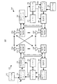
[“Default PDSCH time domain resource allocation A for normal CP”と題する、3GPP TS 38.214 V15.2.0の表5.1.2.1.1−2は、図8として複製される。]
[“Default PDSCH time domain resource allocation A for extended CP”と題する、3GPP TS 38.214 V15.2.0の表5.1.2.1.1−3は、図9として複製される。]
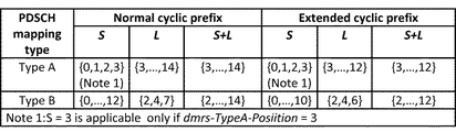
[“Default PDSCH time domain resource allocation B”と題する、3GPP TS 38.214 V15.2.0の表5.1.2.1.1−4は、図10として複製される。]
[“Default PDSCH time domain resource allocation C”と題する、3GPP TS 38.214 V15.2.0の表5.1.2.1.1−5は、図11として複製される。]
[外4]
[外5]
[“PDSCH processing time for PDSCH processing capability 2”と題する、3GPP TS 38.214 V15.2.0の表5.3−2は、図14として複製される。]
3GPP TS 38.214 provides some explanations related to PDSCH as follows:
[Outside 1]
[Outside 2]
[Outside 3]
[Table 5.1.2.1.1-2 of 3GPP TS 38.214 V15.2.0, entitled “Default PDSCH time domain resource allocation A for normal CP”, is reproduced as FIG. ]
[Table 5.1.2.1.3 of 3GPP TS 38.214 V15.2.0, entitled “Default PDSCH time domain resource allocation A for extended CP”, is reproduced as FIG. ]
[Table 5.1.2.1.1-4 of 3GPP TS 38.214 V15.2.0, entitled “Default PDSCH time domain resource allocation B”, is reproduced as FIG. ]
[Table 5.1.2.1.1-5 of 3GPP TS 38.214 V15.2.0, entitled “Default PDSCH time domain resource allocation C”, is reproduced as FIG. ]
[Outside 4]
[Outside 5]
[Table 5.3-2 of 3GPP TS 38.214 V15.2.0, entitled "PDSCH processing time for
3GPP TS 38.212は、PDSCHに関連したいくつかの説明を以下のように提供している:
[外6]
[Outside 6]
3GPP TS 38.321は、DLSCH(下りリンク共有チャネル:Downlink Shared Channel)およびBWP(帯域幅部分:Bandwidth Part)に関連した以下の説明を提供している:
[外7]
[Outside 7]
3GPP TS 38.213は、PDCCH(物理下りリンク制御チャネル:Physical Downlink Control Channel)およびBWP(帯域幅部分:Bandwidth Part)に関連した以下の説明を提供している:
[外8]
[Outside 8]
R1−1710838は、クロススロットスケジューリングのメカニズムに関連した以下の説明を提供している:
[外9]
[Outside 9]
5G/NRでは、スロット内またはスロットにまたがるPDCCHの監視機会は、背景技術において述べたようにフレキシブルに設定され得る。PDSCHの時間領域リソースは、PDCCHで搬送されるその関連するDCI(下りリンク制御情報)の時間領域リソース割り当てフィールドに従って割り当てられ得る。時間領域リソース割り当てフィールドの各状態または値(例えば、“0001”)は、スロットオフセット、開始シンボル、割り当て長さにマッピングされ得る。いったんPDSCHをスケジューリングし、時間領域リソース割り当てフィールドにおいて値を示すPDCCHをUEが受信したら、UEは、その値にマッピングされたスロットオフセット、開始シンボル、割り当て長さに従って、どのスロットおよびどのシンボルでPDSCHを受信するかを決定することができる。 At 5G / NR, PDCCH monitoring opportunities within or across slots can be flexibly set as described in the background art. The PDSCH time domain resource can be allocated according to its associated DCI (downlink control information) time domain resource allocation field carried by the PDCCH. Each state or value of the time domain resource allocation field (eg, "0001") can be mapped to a slot offset, start symbol, allocation length. Once the PDSCH is scheduled and the UE receives a PDCCH indicating a value in the time domain resource allocation field, the UE sets the PDSCH in which slot and which symbol according to the slot offset, start symbol, and allocation length mapped to that value. You can decide whether to receive it.
例えば、UEは、スロットの先頭(beginning)、例えば、スロットの最初の1〜3シンボルでPDCCHを監視することができる。PDCCHでのDCIの時間領域リソース割り当てフィールドが、PDSCHがスロットの先頭(例えば、スロットの最初の4つのシンボルのいずれか)から割り当てられることを示すことができる場合、UEは、それがPDCCHでの対応するDCIの受信および復号を完了する前に、潜在的なPDSCHのためにDLシンボルを受信またはバッファしなければならないことがある。潜在的なPDSCHの最も早い割り当てられたシンボルが、PDCCHの監視機会内の最後のシンボルの後ろにある場合であっても、UEがDCIの復号を完了するのにはその間の間隙が不十分である限りは、UEは、潜在的なPDSCHのためにDLシンボルを受信またはバッファしなければならないことがあることに留意されたい。この構造を達成するため、UEは、最初のDL(もしくはフレキシブルシンボル)から、あるいはPDSCHに割り当てられ得る最も早いシンボルから、完全にアクティブなBWPの信号を捕捉しなければならない。なぜなら、最も大きい帯域幅が割り当てられ得ると仮定されるべきであるように、いずれにしてもDCIが復号される前に周波数領域リソース割り当てをUEは知ることができないためである。DCIの受信および復号を完了した後、UEはこのスロットにおいて任意のPDSCHが受信されるものであるかどうかを知る。このスロットにおいてPDSCHが送信されない場合、UEはDLデータの受信を停止することができる。 For example, the UE can monitor the PDCCH at the beginning of the slot, eg, the first 1-3 symbols of the slot. If the DCI time domain resource allocation field in the PDCCH can indicate that the PDSCH is allocated from the beginning of the slot (eg, one of the first four symbols in the slot), the UE tells it that it is in the PDCCH. It may be necessary to receive or buffer DL symbols for potential PDSCH before completing the reception and decoding of the corresponding DCI. Even if the earliest assigned symbol of the potential PDSCH is after the last symbol in the PDCCH monitoring opportunity, there is not enough space between them for the UE to complete the decoding of the DCI. Note that as long as the UE may have to receive or buffer DL symbols for potential PDSCH. To achieve this structure, the UE must capture the fully active BWP signal from the first DL (or flexible symbol) or from the earliest symbol that can be assigned to the PDSCH. This is because the UE cannot know the frequency domain resource allocation before the DCI is decoded in any case, as it should be assumed that the largest bandwidth can be allocated. After completing the reception and decryption of the DCI, the UE knows if any PDSCH is to be received in this slot. If no PDSCH is transmitted in this slot, the UE can stop receiving DL data.
電力消費の観点から、UEは、スロット内の最初のあるいは最も早いDLまたはフレキシブルシンボルから、UEがこのスロット内で送信されるDCIの検出および復号を完了するまで、PDSCHの受信を可能とするのに本当に必要とされる電力よりも多くの電力を消費する。UEが時間領域で対応するDCIの復号を完了する前に、PDSCHが割り当てられないことがUEに保証される場合、UEは、PDSCHの受信についての電力を節約することができる。例えば、UEが、DCIの復号を完了する前に、潜在的なPDSCHを受信する必要がない場合、UEは、アクティブな帯域幅部分よりも(かなり)小さい帯域幅部分、例えば、UEが監視したCORESETの帯域幅部分に類似するか、あるいはそれと同じ帯域幅部分において、PDCCH監視中にDL信号を受信することができる。 From the point of view of power consumption, the UE allows the reception of PDSCH from the first or earliest DL or flexible symbol in the slot until the UE completes the detection and decoding of the DCI transmitted in this slot. Consume more power than is really needed. If the UE is guaranteed that no PDSCH is allocated before the UE completes decoding of the corresponding DCI in the time domain, the UE can save power for receiving the PDSCH. For example, if the UE does not need to receive a potential PDSCH before it completes decoding the DCI, then the UE monitors a bandwidth portion that is (significantly) smaller than the active bandwidth portion, eg, the UE. A DL signal can be received during PDCCH monitoring in a bandwidth portion similar to or similar to the bandwidth portion of CORESET.
一般的な概念の1つは、UEが(特定の)シンボルよりも早い最初のシンボルを有するPDSCHを示すDCIを受信するかどうかを、gNBがUEに知らせることができるということである。その(特定の)シンボルは、UEがDCIの受信および/または復号を完了するのに必要な時間に従って決定され得る。その(特定の)シンボルは、UEがPDSCHの受信を準備する、あるいはそのための準備が整うのに必要な時間に従って決定され得る。例えば、UEは、UEが監視するCORESETのより小さい帯域幅から、アクティブな帯域幅部分のより大きな帯域幅へ、その受信帯域幅を調整する必要があることがある。その特定のシンボルは、UEがDCIの受信および/または復号を完了するシンボルである、かつ/あるいはUEがPDSCHの受信のための準備が整うシンボルとすることができる。 One general concept is that the gNB can inform the UE whether it will receive a DCI indicating a PDSCH with the first symbol earlier than the (specific) symbol. The (specific) symbol may be determined according to the time required for the UE to complete receiving and / or decoding the DCI. The (specific) symbol may be determined according to the time required for the UE to prepare or be ready to receive the PDSCH. For example, the UE may need to adjust its receive bandwidth from the smaller bandwidth of the CORESET monitored by the UE to the larger bandwidth of the active bandwidth portion. The particular symbol can be a symbol in which the UE completes receiving and / or decoding the DCI and / or the UE is ready to receive the PDSCH.
gNBはどのシンボルがその(特定の)シンボルであるかをUEに通知する。gNBおよびUEはどのシンボルが最初のシンボルであるかを取り決める。UEのために設定されたPDSCHのためのいくつかの時間領域リソース割り当ては、その(特定の)シンボルよりも早い最初または開始シンボルを伴う。UEは、その情報が適用可能な場合、その(特定の)シンボルよりも早い最初または開始シンボルで時間領域リソース割り当てを示すDCIを受信することは期待されない。gNBは、UEへのPDSCHを示すDCIのリソース割り当てを知っている。gNBが、UEのDCIを検出および復号する能力を知っている場合、gNBはUEがDCIの復号を完了する時間を推定し、対応するDCIによって示されるPDSCHの割り当てを見つけることができる。 The gNB informs the UE which symbol is that (specific) symbol. The gNB and UE negotiate which symbol is the first symbol. Some time domain resource allocation for PDSCH configured for a UE involves an earlier first or start symbol than its (specific) symbol. The UE is not expected to receive a DCI indicating time domain resource allocation at the first or start symbol earlier than the (specific) symbol, if that information is applicable. The gNB knows the DCI resource allocation that indicates the PDSCH to the UE. If the gNB knows the ability of the UE to detect and decode the DCI, the gNB can estimate the time it takes for the UE to complete decoding the DCI and find the PDSCH assignment indicated by the corresponding DCI.
持続時間T1(time duration)が、UEがDCIを受信してからDCIの復号を完了し、DCIによって示されるPDSCH割り当てを知るまでとすると、PDSCHの開始シンボルとUEが対応するDCIを受信するシンボルの間の時間継続がT1より短くないことをUEが知っている場合、UEがPDSCHを示すDCIを検出し、復号する前に、UEは潜在的なPDSCHを受信することができない。例えば、UEがPDSCHを示すDCIを検出し、復号する前に、UEはアクティブ帯域幅部分の帯域幅を受信する必要はない。UEは、PDSCHを示すDCIを検出し、復号する前に、アクティブ帯域幅部分の帯域幅よりも小さい(特定の)帯域幅を受信する。(特定の)帯域幅は、UEが監視するCORSETの帯域幅である。UEは、DCIによって示されるPDSCHの最初のシンボルの前に、アクティブ帯域幅部分の帯域幅を受信する必要はない。UEは、DCIによって示されるPDSCHの最初のシンボルの前に、アクティブ帯域幅部分の帯域幅よりも小さい(特定の)帯域幅を受信する。(特定の)帯域幅は、UEが監視するCORSETの帯域幅である。 Assuming that the duration T1 (time duration) is from the time the UE receives the DCI to the time it completes decoding the DCI and knows the PDSCH allocation indicated by the DCI, the start symbol of the PDSCH and the symbol that the UE receives the corresponding DCI. If the UE knows that the time duration between is not shorter than T1, the UE cannot receive the potential PDSCH before the UE detects and decodes the DCI indicating the PDSCH. For example, the UE does not need to receive the bandwidth of the active bandwidth portion before the UE detects and decodes the DCI indicating PDSCH. The UE receives a (specific) bandwidth that is smaller than the bandwidth of the active bandwidth portion before detecting the DCI indicating the PDSCH and decoding it. The (specific) bandwidth is the bandwidth of the CORESET monitored by the UE. The UE does not need to receive the bandwidth of the active bandwidth portion before the first symbol of the PDSCH indicated by DCI. The UE receives a (specific) bandwidth that is less than the bandwidth of the active bandwidth portion before the first symbol of the PDSCH indicated by DCI. The (specific) bandwidth is the bandwidth of the CORESET monitored by the UE.
UEが(特定の)シンボルより早い最初のシンボルを有するPDSCHを示すDCIを受信するかどうかについての情報は、すべてのスロットに適用可能である。UEが(特定の)シンボルより早い最初のシンボルを有するPDSCHを示すDCIを受信するかどうかについての情報は、スロットnに適用可能である。スロットnは、UEがDCIを受信しなかった別のスロット、例えば、UEがDCIを受信しなかったスロットn−1の次のスロットである。スロットnは、UEがDCIを受信しなかった複数のスロット、例えば、UEがDCIを受信しなかったスロットn−x〜n−1の後のスロットである。スロットnは、オンデュレーション(on duration)の最初のスロットである。UEは、UEが対応するDCIの復号を完了する前に、PDSCHの受信について電力を節約することができる。 Information about whether the UE receives a DCI indicating a PDSCH with the first symbol earlier than the (specific) symbol is applicable to all slots. Information about whether the UE receives a DCI indicating a PDSCH with the first symbol earlier than the (specific) symbol is applicable to slot n. Slot n is the slot next to another slot in which the UE did not receive DCI, eg, slot n-1 in which the UE did not receive DCI. Slot n is a plurality of slots in which the UE did not receive DCI, for example, slots after slots n-x to n-1 in which the UE did not receive DCI. Slot n is the first slot of on duration. The UE can save power for receiving the PDSCH before the UE completes decoding of the corresponding DCI.
一実施形態では、gNBは、この方法を有効/無効にするための信号をUEに送信する。この信号は、PDSCHの開始シンボルが、UEが時間領域で対応するDCIの復号を完了するよりも早いかどうかを通知することができる。この信号は、以前のPDSCHで言及されてよい。 In one embodiment, the gNB sends a signal to the UE to enable / disable this method. This signal can signal whether the PDSCH start symbol is earlier than the UE completes decoding the corresponding DCI in the time domain. This signal may be mentioned in previous PDSCHs.
一実施形態では、その信号がこの方法を無効にする値に設定されることをUEが検出する場合、UEは、DCIによって示される次のPDSCHの最初のシンボルと対応するDCIの間の持続時間がT1より短い可能性があることを知ることができる。代替的には、その信号がこの方法の有効にする値に設定されることをUEが検出する場合、UEは、DCIによって示される次のPDSCHの最初のシンボルと対応するDCIの間の持続時間がT1より短くないことを知ることができる。 In one embodiment, if the UE detects that the signal is set to a value that invalidates this method, the UE will have a duration between the first symbol of the next PDSCH indicated by the DCI and the corresponding DCI. Can be found that may be shorter than T1. Alternatively, if the UE detects that the signal is set to a value enabled by this method, the UE will have a duration between the first symbol of the next PDSCH indicated by the DCI and the corresponding DCI. Can be seen that is not shorter than T1.
一実施形態では、その信号がPDSCHを示す1つのDCIに添付されない場合、UEは、無効信号が受信されたと仮定することができる。代替的には、その信号がPDSCHを示す1つのDCIに添付されない場合、UEは、有効信号が受信されたと仮定することができる。 In one embodiment, if the signal is not attached to one DCI indicating PDSCH, the UE can assume that an invalid signal has been received. Alternatively, if the signal is not attached to one DCI indicating PDSCH, the UE can assume that a valid signal has been received.
一実施形態では、前のPDSCHが受信されない場合、gNBは、PDSCHの最初のシンボルと対応するDCIの間の持続時間がT1より短くなるようなPDSCHを割り当てることが許可されない。その信号は、次のPDSCH送信のみを指示してよい。その信号はまた、その後の多数のPDSCH送信を指示してよい。追加的に、その信号は、1つまたは複数のその後のスロットにおけるPDSCH送信を指示してよい。さらに、この信号は、UEが別の有効または無効信号を検出するまで、すべてのPDSCH送信を指示してよい。 In one embodiment, if the previous PDSCH is not received, the gNB is not allowed to assign a PDSCH such that the duration between the first symbol of the PDSCH and the corresponding DCI is less than T1. The signal may only direct the next PDSCH transmission. The signal may also direct a number of subsequent PDSCH transmissions. Additionally, the signal may direct PDSCH transmission in one or more subsequent slots. In addition, this signal may direct all PDSCH transmissions until the UE detects another valid or invalid signal.
UEが、PDSCH送信の開始シンボルと対応するDCIの間の持続時間の割り当てがT1より短くない設定で設定され、かつ、時間領域関係を満足しない、PDSCHを示すDCIを受信する場合、UEはPDSCHを受信しなくてもよく、対応するHARQにおいて、NACKを送信してよい。 When the UE receives a DCI indicating PDSCH, the duration allocation between the start symbol of PDSCH transmission and the corresponding DCI is set not to be shorter than T1 and does not satisfy the time domain relationship, the UE receives PDSCH. You do not have to receive the NACK, and you may send the NACK in the corresponding HARQ.
図15は、UEが電力を節約するのを助けるために、この信号が時間領域でどのように作用するかの例を示す。次のPDSCH送信の最初のシンボルが時間領域関係に従うかどうかを表すために、信号がPDSCHに添付される。図15において、UEは最初のPDSCHにおいて有効の値を有する信号を検出し、UEは、UEが対応するDCIを受信してからT1後に次のPDSCHを受信されるものであることを知る。次いで、gNBは次のスロットにおいてPDSCHを示すDCIを送信する。PDSCHとPDSCHを示すDCIは時間領域関係に従うため、UEがこのPDSCHを示すDCIを検出した後、gNBはT1で次のPDSCHを割り当てる。UEは、最初のPDSCHの終わりから、PDSCHを示すDCIの復号をUEが完了するまで、PDSCHを受信しない。UEは、これらの2つのPDSCHの間で、潜在的なPDSCHを受信することについての電力を節約することができる。2番目のPDSCHには、無効の値に設定された信号が添付されている。これは、次のPDSCH割り当てがT1の時間領域関係に従わなくてもよいことを意味する。従って、UEは、次のスロットの最初のDLまたはフレキシブルシンボルからPDSCHを受信しなければならない。 FIG. 15 shows an example of how this signal works in the time domain to help the UE save power. A signal is attached to the PDSCH to indicate whether the first symbol of the next PDSCH transmission follows a time domain relationship. In FIG. 15, the UE detects a signal having a valid value in the first PDSCH, and the UE knows that the UE receives the corresponding DCI and then receives the next PDSCH after T1. The gNB then transmits a DCI indicating PDSCH in the next slot. Since the PDSCH and the DCI indicating the PDSCH follow the time domain relationship, the gNB allocates the next PDSCH at T1 after the UE detects the DCI indicating the PDSCH. The UE does not receive the PDSCH from the end of the first PDSCH until the UE completes decoding of the DCI indicating the PDSCH. The UE can save power for receiving a potential PDSCH between these two PDSCHs. A signal set to an invalid value is attached to the second PDSCH. This means that the next PDSCH allocation does not have to follow the time domain relationship of T1. Therefore, the UE must receive the PDSCH from the first DL or flexible symbol in the next slot.
一実施形態では、SPS PDSCH送信が設定される場合、gNBは、SPS PDSCHにおいてこの信号を示すことができる。別の概念は、UEが時間領域で対応するDCIの検出および受信を完了する時間よりも早いPDSCHの割り当てを有効または無効にするためのRRCパラメータでUEが設定され得るということである。パラメータが無効の値に設定される場合、gNBは、UEが対応するDCIの復号を完了する時間よりも早いPDSCHの開始シンボルを有するPDSCHをUEに割り当てることが許可されなくてよい。UEは、対応するDCIを復号する前に、PDSCHを受信することについて電力を節約することができる。パラメータが有効に設定される場合、gNBは、UEが時間領域で対応するDCIの復号を完了する時間より遅いPDSCH割り当てを制限しない。UEは依然として、スロットの最初のDLまたはフレキシブルシンボルからPDSCHを受信しなければならない。一実施形態では、PDSCHと対応するDCIの間の時間領域関係の設計は、UEごとに、セルごとに、あるいはBWPごとに、有効または無効にすることができる。 In one embodiment, if SPS PDSCH transmission is configured, the gNB can indicate this signal in the SPS PDSCH. Another concept is that the UE can be configured with RRC parameters to enable or disable PDSCH allocation earlier than the time it takes to complete the detection and reception of the corresponding DCI in the time domain. If the parameter is set to an invalid value, the gNB may not be allowed to assign a PDSCH to the UE with a PDSCH start symbol earlier than the time it takes for the UE to complete decoding of the corresponding DCI. The UE can save power on receiving the PDSCH before decoding the corresponding DCI. When the parameter is enabled, the gNB does not limit PDSCH allocations that are slower than the time the UE completes decoding the corresponding DCI in the time domain. The UE still has to receive the PDSCH from the first DL or flexible symbol in the slot. In one embodiment, the design of the time domain relationship between the PDSCH and the corresponding DCI can be enabled or disabled on a UE-by-UE, cell-by-cell, or BWP-by-BWP basis.
一実施形態では、gNBは、UEに下りリンクデータを送信するために使用される周波数領域リソース割り当てを、gNBが使用できる最大帯域幅よりも小さい範囲に制限する。UEが、PDSCHを受信する可能性がある周波数範囲が制限されることを知っている場合、UEは、対応するDCIにおけるPDSCHの周波数領域リソース割り当てを復号する前は、最大帯域幅で送信されるすべての信号を受信する必要はない。UEは、DCIが示したPDSCHの時間および周波数領域で復号する前は、PDSCHを受信する可能性のあるgNBによって示される周波数範囲においてのみ信号を受信することができる。 In one embodiment, the gNB limits the frequency domain resource allocation used to transmit downlink data to the UE to a range smaller than the maximum bandwidth available to the gNB. If the UE knows that the frequency range in which it may receive the PDSCH is limited, the UE is transmitted at maximum bandwidth before decoding the PDSCH frequency domain resource allocation in the corresponding DCI. It is not necessary to receive all signals. The UE can receive the signal only in the frequency range indicated by the gNB which may receive the PDSCH before decoding in the PDSCH time and frequency domain indicated by DCI.
別の一般的な概念は、PDSCHをUEに送信するために使用される周波数領域リソース割り当てが、PDSCHの最初のシンボルに依存するUEのアクティブ帯域幅部分の一部に制限されているかどうかを、gNBがUEに通知することである。アクティブ帯域幅部分の一部は、UEが監視するCORESETの帯域幅とすることができる。また、アクティブ帯域幅部分の一部はまた、UEが監視するCORESETの周波数リソースまたは物理リソースブロックとすることができる。 Another general concept is whether the frequency domain resource allocation used to send the PDSCH to the UE is limited to a portion of the UE's active bandwidth portion that depends on the first symbol of the PDSCH. The gNB notifies the UE. A portion of the active bandwidth portion can be the bandwidth of the CORESET monitored by the UE. Also, part of the active bandwidth portion can also be a CORESET frequency resource or physical resource block monitored by the UE.
例えば、PDSCHの最初のシンボルが(特定の)シンボルよりも早い場合、周波数領域リソース割り当ては、アクティブ帯域幅部分の一部に制限され得る。代替的には、PDSCHの最初のシンボルが(特定の)シンボルよりも遅い場合、周波数領域リソース割り当ては、アクティブ帯域幅部分の一部に限定されなくてもよく、例えば、周波数リソース割り当ては、アクティブ帯域幅部分の全体または全部に対してなされ得る。(特定の)シンボルは、UEがDCIの受信および/または復号を完了するのに必要な時間に従って決定され得る。(特定の)シンボルはまた、UEがPDSCHの受信を準備する/PDSCHのための準備が整うのに必要な時間に従って決定され得る。 For example, if the first symbol of the PDSCH is earlier than the (specific) symbol, the frequency domain resource allocation may be limited to a portion of the active bandwidth portion. Alternatively, if the first symbol of the PDSCH is slower than the (specific) symbol, the frequency domain resource allocation may not be limited to a portion of the active bandwidth portion, eg, the frequency resource allocation is active. It can be done for all or all of the bandwidth portion. The (specific) symbol may be determined according to the time required for the UE to complete receiving and / or decoding the DCI. The (specific) symbol can also be determined according to the time required for the UE to be ready to receive the PDSCH / ready for the PDSCH.
例えば、UEは、より小さい1つの帯域幅(例えば、UEが監視するCORESETの帯域幅)からより大きな1つの帯域幅(例えば、アクティブ帯域幅部分の帯域幅)へその受信帯域幅を調整する必要があることがある。特定のシンボルは、UEがDCIの受信および復号を完了するシンボル、および/またはUEがPDSCHの受信の準備が整うシンボルとすることができる。gNBはどのシンボルがその(特定の)シンボルであるかをUEに通知する。gNBおよびUEはどのシンボルが最初のシンボルであるかを取り決める。UEのために設定されるPDSCHのための時間領域リソース割り当てのいくつか(一部)は、その(特定の)シンボルよりも早い最初の/開始シンボルを伴うことができる。UEは、(特定の)シンボルより早い最初または開始シンボルを有する時間領域リソース割り当てを示し、情報が適用される場合、UEのアクティブ帯域幅部分の一部の外側の周波数領域リソース割り当てを示すDCIを受信することは期待されない。 For example, the UE needs to adjust its receive bandwidth from one smaller bandwidth (eg, the bandwidth of the CORESET monitored by the UE) to one larger bandwidth (eg, the bandwidth of the active bandwidth portion). There may be. The particular symbol can be a symbol in which the UE completes receiving and decoding DCI and / or a symbol in which the UE is ready to receive PDSCH. The gNB informs the UE which symbol is that (specific) symbol. The gNB and UE negotiate which symbol is the first symbol. Some (part) of the time domain resource allocation for the PDSCH configured for the UE can be accompanied by an earlier / start symbol than that (specific) symbol. The UE indicates a time domain resource allocation with a first or start symbol earlier than the (specific) symbol, and if the information is applied, a DCI indicating a frequency domain resource allocation outside a portion of the UE's active bandwidth portion. Not expected to be received.
UEが早くにPDSCHを受信する可能性がある周波数範囲が制限されていることを知っている場合、UEが対応するDCIを復号する前に、UEは、アクティブ帯域幅部分で送信されるすべての信号を受信する必要はない。UEがDCIを復号する前に、UEはPDSCHを受信する可能性があるアクティブ帯域幅部分の一部においてのみ信号を受信することができる。UEがアクティブ帯域幅部分の外側の周波数領域リソース割り当てを伴うPDSCHを示すDCIを受信する場合、最初または開始シンボルは、UEがPDSCHのための受信を準備する、例えば、その受信帯域幅を調整することができる(特定の)シンボルよりも遅い。 If the UE knows that the frequency range in which it may receive the PDSCH early is limited, the UE will send all transmissions in the active bandwidth portion before the UE decodes the corresponding DCI. There is no need to receive a signal. Before the UE decodes the DCI, the UE can receive the signal only in a portion of the active bandwidth portion where it may receive the PDSCH. When the UE receives a DCI indicating a PDSCH with a frequency domain resource allocation outside the active bandwidth portion, the first or start symbol prepares the UE for reception for the PDSCH, eg, adjusts its receive bandwidth. Can be slower than a (specific) symbol.
例えば、UEがPDSCHを示すDCIを検出し、復号する前に、UEはアクティブ帯域幅部分の帯域幅を受信する必要はない。UEは、PDSCHを示すDCIを検出し、復号する前に、アクティブ帯域幅部分の帯域幅よりも小さい(特定の)帯域幅を受信することができる。(特定の)帯域幅は、UEが監視するCORSETの帯域幅とすることができる。UEは、DCIによって示されるPDSCHの最初のシンボルの前に、アクティブ帯域幅部分の帯域幅を受信する必要はない。 For example, the UE does not need to receive the bandwidth of the active bandwidth portion before the UE detects and decodes the DCI indicating PDSCH. The UE can receive a (specific) bandwidth that is smaller than the bandwidth of the active bandwidth portion before detecting the DCI indicating the PDSCH and decoding it. The (specific) bandwidth can be the bandwidth of the CORESET monitored by the UE. The UE does not need to receive the bandwidth of the active bandwidth portion before the first symbol of the PDSCH indicated by DCI.
さらに、UEは、DCIによって示されるPDSCHの最初のシンボルの前に、アクティブ帯域幅部分の帯域幅よりも小さい(特定の)帯域幅を受信することができる。その(特定の)帯域幅は、UEが監視するCORSETの帯域幅とすることができる。UEが(特定の)シンボルよりも早い最初のシンボルを有するPDSCHを示すDCIを受信するかどうかの情報は、すべてのスロットに適用可能である。代替的には、UEが(特定の)シンボルよりも早い最初のシンボルを有するPDSCHを示すDCIを受信するかどうかの情報は、スロットnに適用可能としてよい。スロットnはまた、UEがDCIを受信しなかった別のスロット(例えば、UEがDCIを受信しなかったスロットn−1)の次のスロットとすることができる。スロットnは、UEがDCIを受信しなかった複数のスロット(例えば、UEがDCIを受信しなかったスロットn−x〜n−1)の後のスロットとすることができる。スロットnは、オンデュレーションの最初のスロットとすることができる。 In addition, the UE can receive a (specific) bandwidth that is less than the bandwidth of the active bandwidth portion before the first symbol of the PDSCH indicated by DCI. The (specific) bandwidth can be the bandwidth of the CORESET monitored by the UE. Information on whether the UE receives a DCI indicating a PDSCH with the first symbol earlier than the (specific) symbol is applicable to all slots. Alternatively, information on whether the UE receives a DCI indicating a PDSCH with the first symbol earlier than the (specific) symbol may be applicable to slot n. Slot n can also be the slot next to another slot in which the UE did not receive DCI (eg, slot n-1 in which the UE did not receive DCI). Slot n can be a slot after a plurality of slots in which the UE did not receive DCI (eg, slots n-x to n-1 in which the UE did not receive DCI). Slot n can be the first slot of onduration.
一実施形態では、gNBはUEに、周波数領域でのこの制限の方法を有効または無効にするための信号を送信する。この信号は、PDSCHの周波数領域割り当てが、gNBが使用できる最大帯域幅よりも小さい周波数範囲に制限されるかどうかを通知することができる。この信号はまた、制限された周波数範囲の割り当てを示すことができる。この信号は、前のPDSCHで言及されてよい。 In one embodiment, the gNB sends a signal to the UE to enable or disable this limiting method in the frequency domain. This signal can signal whether the PDSCH frequency domain allocation is limited to a frequency range smaller than the maximum bandwidth available to the gNB. This signal can also indicate a limited frequency range allocation. This signal may be mentioned in the previous PDSCH.
一実施形態では、その信号がこの方法を無効にする値に設定されていることをUEが検出する場合、UEは、次のPDSCHが、gNBが使用してよい最大可能帯域幅よりも小さい制限帯域幅で送信されることを知る。制限帯域幅の範囲は、gNBによって決定されてよい。UEは、gNBの制限帯域幅の範囲を得てよい。一実施形態では、制限帯域幅の範囲は、UEが監視しなければならないCORSETに基づいて、有効信号を有する前のPDSCHのリソース割り当てに基づいて、あるいは現在のアクティブDL BWPの周波数割り当てに基づいて設定されてよい。 In one embodiment, if the UE detects that the signal is set to a value that disables this method, the UE limits the next PDSCH to less than the maximum possible bandwidth that the gNB may use. Know that it is transmitted in bandwidth. The range of limited bandwidth may be determined by gNB. The UE may obtain a limited bandwidth range of gNB. In one embodiment, the limited bandwidth range is based on the CORESET that the UE must monitor, based on the resource allocation of the PDSCH before having a valid signal, or based on the frequency allocation of the current active DL BWP. May be set.
一実施形態では、その信号がこの方法の有効にする値に設定されていることをUEが検出する場合、UEは、DCIによって示される次のPDSCHが制限帯域幅内に割り当てられることを知る。周波数領域制限は、T1の時間領域制限を満たさないPDSCH送信のみを制限してよい。一実施形態では、信号がPDSCHを示す一つのDCIに添付されない場合、UEは、DCIによって示される次のPDSCHの開始シンボルが、制限帯域幅内のみでは割り当てられない可能性があると見なしてよい。代替的には、この信号がPDSCHを示す一つのDCIに添付されない場合、UEは、DCIによって示される次のPDSCHの開始シンボルが、制限帯域幅内のみ割り当てられなくてよいと見なしてよい。 In one embodiment, if the UE detects that the signal is set to a value enabled by this method, the UE knows that the next PDSCH indicated by DCI will be allocated within the limited bandwidth. The frequency domain limitation may limit only PDSCH transmissions that do not meet the T1 time domain limitation. In one embodiment, if the signal is not attached to one DCI indicating PDSCH, the UE may consider that the start symbol of the next PDSCH indicated by DCI may not be assigned only within the limited bandwidth. .. Alternatively, if this signal is not attached to one DCI indicating the PDSCH, the UE may consider that the start symbol of the next PDSCH indicated by the DCI need not be allocated only within the limited bandwidth.
一実施形態では、前のPDSCHが受信されない場合、gNBは、制限帯域幅内でPDSCHを示したDCIを割り当てることのみが許される。その信号は、次のPDSCH送信のみを示してよい。さらに、その信号は、その後の多数のPDSCH送信を示してよい。その信号はまた、1つまたは複数のその後のスロットにおけるPDSCH送信を示してよい。追加的に、UEが別の有効または無効信号を検出するまで、その信号はすべてのPDSCH送信を示してよい。 In one embodiment, if the previous PDSCH is not received, the gNB is only allowed to allocate a DCI indicating the PDSCH within the limited bandwidth. The signal may indicate only the next PDSCH transmission. In addition, the signal may indicate a number of subsequent PDSCH transmissions. The signal may also indicate PDSCH transmission in one or more subsequent slots. Additionally, until the UE detects another valid or invalid signal, that signal may indicate all PDSCH transmissions.
図16は、この方法が、潜在的なPDSCHを監視するのについて、UEが電力を節約するのをどのように助けるかの一例を示す。図16の第1のPDSCHは、この方法を有効にすることを示す信号に添付される。UEは、DCIによって示される次のPDSCHが、UEが監視するCORESETの範囲内の周波数帯でのみ送信されることを知っている。UEは、CORESET内の周波数でのみ潜在的なPDSCHを受信し、アクティブBWPの全体または全部を監視するわけではない。図16の第2のPDSCHは、無効を示す信号が添付される。UEは、第3のPDSCHが、UEが監視するものとするCORESETの周波数範囲内のみだけではない範囲に割り当てられる可能性があることを知る。UEは、完全なアクティブBWPを監視することによって、潜在的なPDSCHを受信しなければならない。 FIG. 16 shows an example of how this method helps the UE save power for monitoring potential PDSCH. The first PDSCH of FIG. 16 is attached to a signal indicating that this method is valid. The UE knows that the next PDSCH indicated by DCI will only be transmitted in a frequency band within the range of CORESET monitored by the UE. The UE receives the potential PDSCH only at frequencies within CORESET and does not monitor all or all of the active BWP. A signal indicating invalidity is attached to the second PDSCH of FIG. The UE knows that the third PDSCH may be assigned to a range other than just within the CORESET frequency range that the UE is supposed to monitor. The UE must receive the potential PDSCH by monitoring the full active BWP.
一実施形態では、UEが、PDSCH送信の割り当てが制限帯域幅内のみとなる設定で設定され、UEが、周波数制限を満たさないPDSCHを示すDCIを受信する場合、UEは、このPDSCHを受信できず、対応するHARQにおいてNACKを送信する。 In one embodiment, if the UE is configured to allocate PDSCH transmissions only within the limited bandwidth and the UE receives a DCI indicating a PDSCH that does not meet the frequency limit, the UE can receive this PDSCH. Instead, NACK is transmitted in the corresponding HARQ.
一実施形態では、PDSCH割り当ての周波数領域制限の設計は、UEごとに有効または無効にされ得る。PDSCH割り当ての周波数領域制限の設計は、セルごとあるいはBWPごとに有効または無効にされ得る。 In one embodiment, the PDSCH allocation frequency domain limiting design can be enabled or disabled on a UE-by-UE basis. The frequency domain limitation design for PDSCH allocation can be enabled or disabled on a cell-by-cell or BWP-by-cell basis.
RRC(無線リソース制御:Radio Resource Control)パラメータは、PDSCHにおける信号添付を有効または無効にするように設定されてよい。一実施形態では、RRCパラメータは、UE固有、セル固有、またはBWP固有に設定され得る。RRCパラメータがこの方法を有効にする値に設定される場合、gNBは、その後のPDSCH送信の最初のシンボルがUEが対応するDCIの復号を完了するよりも早い可能性があるかどうかを示す信号をPDSCH送信に添付することができる。代替的には、RRCパラメータがこの方法を無効にする値に設定される場合、gNBは信号をPDSCH送信に添付しなくてもよい。 The RRC (Radio Resource Control) parameter may be set to enable or disable signal attachment in the PDSCH. In one embodiment, the RRC parameters can be set to be UE-specific, cell-specific, or BWP-specific. If the RRC parameter is set to a value that enables this method, the gNB is a signal indicating whether the first symbol of a subsequent PDSCH transmission may be faster than the UE completes decoding of the corresponding DCI. Can be attached to the PDSCH transmission. Alternatively, if the RRC parameter is set to a value that disables this method, the gNB does not have to attach the signal to the PDSCH transmission.
一実施形態では、RRCパラメータがこの方法を無効にする値に設定される場合、gNBは、UEが時間領域において対応するDCIの復号を完了する時間よりも早いPDSCHの最初のシンボルを有するPDSCHを示すDCIを送信してよい。 In one embodiment, when the RRC parameter is set to a value that invalidates this method, the gNB has a PDSCH with the first symbol of the PDSCH that is earlier than the time the UE completes decoding the corresponding DCI in the time domain. The indicated DCI may be transmitted.
一実施形態では、UEおよびgNBの両方によって知られているルールが、PDSCHの時間領域および/または周波数領域リソース割り当ての制限(例えば、上述の方法に従った制限)を有効または無効するために使用されてよい。RRCパラメータは、ルールに従って制限を有効または無効するように設定されてよい。RRCパラメータは、UE固有、セル固有、またはBWP固有に設定されることができる。制限が設定される場合、UEおよびgNBはデフォルトで制限を有効にすることができる。 In one embodiment, rules known by both UE and gNB are used to enable or disable time domain and / or frequency domain resource allocation limits for PDSCH (eg, limits according to the methods described above). May be done. The RRC parameters may be set to enable or disable restrictions according to the rules. RRC parameters can be set to be UE-specific, cell-specific, or BWP-specific. If a limit is set, the UE and gNB can enable the limit by default.
一実施形態では、PDSCH制限を有効または無効にするルールは、PDSCH送信に基づいてよい。その制限を有効に設定され、PDSCHが帯域幅部分および/またはセルにおいてN1個の連続スロットで受信される場合、UEおよびgNBはその制限を(自律的に)無効に切り替えることができる。代替的には、その制限が無効に設定され、PDSCHが帯域幅部分および/またはセルにおいてN2個の連続スロットで受信されない場合、UEおよびgNBはその制限を(自律的に)有効に切り替えることができる。 In one embodiment, the rules that enable or disable PDSCH restrictions may be based on PDSCH transmission. If the limit is enabled and the PDSCH is received in N1 contiguous slots in the bandwidth portion and / or cell, the UE and gNB can (autonomously) disable the limit. Alternatively, if the limit is disabled and the PDSCH is not received in N2 contiguous slots in the bandwidth portion and / or cell, the UE and gNB may (autonomously) enable the limit. can.
一実施形態では、その制限が有効に設定され、PDSCHが、帯域幅部分および/またはセルにおいて最新のN1´個の連続スロット内の少なくともN3個のスロットで受信される場合、UEおよびgNBはその制限を(自律的に)無効にするように切り替えることができる。その制限が無効に設定され、PDSCHが帯域幅部分および/またはセルにおいて最新のN2´個の連続スロットのうちのN4個のスロットで受信されない場合、UEおよびgNBはその制限を(自律的に)有効に切り替えることができる。その制限が有効に設定され、サイズがN5個のリソース要素より大きいPDSCHが帯域幅部分および/またはセルにおいて受信される場合、UEおよびgNBは制限を(自律的に)無効に切り替えることができる。制限が無効に設定され、サイズがN6個のリソース要素よりも大きいPDSCHがセルにおいて受信されない場合、UEおよびgNBは制限を(自律的に)有効に切り替えることができる。 In one embodiment, if the limitation is enabled and the PDSCH is received in at least N3 slots within the latest N1'consecutive slots in the bandwidth portion and / or cell, the UE and gNB will have that. You can switch the restriction to (autonomously) disable it. If the limit is disabled and the PDSCH is not received in N4 of the latest N2'consecutive slots in the bandwidth portion and / or cell, the UE and gNB will (autonomously) set the limit. Can be switched to valid. If the limit is enabled and a PDSCH with a size greater than N5 resource elements is received in the bandwidth portion and / or cell, the UE and gNB can (autonomously) disable the limit. If the limit is disabled and no PDSCH larger than N6 resource elements in size is received in the cell, the UE and gNB can (autonomously) enable the limit.
一実施形態では、gNBは、最大可能範囲よりも小さい範囲にPDSCHの割り当てを制限する。gNBはPDSCHの時間領域割り当てを制限する。gNBは、PDSCHの最初のシンボルと対応するDCIの最初のシンボルの間の持続時間がT1より短くないことを制限する。持続時間T1は、UEがDCIを受信してから、UEがこのDCIの復号化を完了し、このDCIによって示されるPDSCHの割り当てを知るまでである。その制限は、UEごと、セルごと、またはBWPごとに有効または無効にされ得る。 In one embodiment, the gNB limits PDSCH allocation to a range smaller than the maximum possible range. gNB limits the time domain allocation of PDSCH. gNB limits the duration between the first symbol of PDSCH and the first symbol of the corresponding DCI not less than T1. The duration T1 is from the time the UE receives the DCI until the UE completes decoding of this DCI and knows the PDSCH allocation indicated by this DCI. The limit can be enabled or disabled per UE, per cell, or per BWP.
この制限は、PDSCHにおける信号を通じて有効または無効にされる。制限が有効に設定される場合、UEは、あるPDSCHの最後のシンボルとその次のPDSCHの開始シンボルの間はPDSCHを受信しない。この方法が無効に設定される場合、PDSCHの最初のシンボルとこのPDSCHを示すDCIの最初のシンボルの間の持続時間がT1より短いPDSCHを示すDCIをUEが受信することが可能である。その信号が有効として検出される場合、その後のPDSCHの最初のシンボルとそのPDSCHを示すDCIの最初のシンボルの間の持続時間は、T1より短くない。その信号が無効として検出される場合、その後のPDSCHの最初のシンボルとそのPDSCHを示すDCIの最初のシンボルの間の持続時間は、T1より短くてよい。SPS PDSCH送信が設定される場合、この時間領域制限の信号は、SPS PDSCH送信に添付される。 This restriction is enabled or disabled through the signal in the PDSCH. When the restriction is enabled, the UE does not receive a PDSCH between the last symbol of one PDSCH and the start symbol of the next PDSCH. If this method is disabled, the UE can receive a DCI indicating a PDSCH with a duration less than T1 between the first symbol of the PDSCH and the first symbol of the DCI indicating this PDSCH. If the signal is detected as valid, the duration between the first symbol of the subsequent PDSCH and the first symbol of DCI indicating the PDSCH is not shorter than T1. If the signal is detected as invalid, the duration between the first symbol of the subsequent PDSCH and the first symbol of the DCI indicating the PDSCH may be shorter than T1. When SPS PDSCH transmission is configured, this time domain limiting signal is attached to the SPS PDSCH transmission.
この信号は、次のPDSCH送信に対する制限を示す。その信号は、その後の多数のスロットにおけるPDSCH送信に対する制限を示す。その信号が検出されない場合、UEは、無効信号が検出されると仮定する。その信号が検出されない場合、UEは、有効信号が検出されると仮定する。以前にUEにPDSCHが設定されていない場合、gNBは、PDSCHの最初のシンボルとこのPDSCHを示すDCIの最初のシンボルの間の持続時間であって、T1よりも短い持続時間でPDSCHを割り当てない。その制限が有効に設定され、UEが時間領域関係に違反するPDSCH送信を示すDCIを受信する場合、UEはこのPDSCHを受信せず、UEは対応するHARQフィードバックでNACKを送信する。 This signal indicates a limitation on the next PDSCH transmission. The signal indicates a limitation on PDSCH transmission in the subsequent numerous slots. If that signal is not detected, the UE assumes that an invalid signal is detected. If that signal is not detected, the UE assumes that a valid signal is detected. If the UE has not previously been configured with PDSCH, gNB will not allocate a PDSCH with a duration between the first symbol of PDSCH and the first symbol of DCI indicating this PDSCH, with a duration shorter than T1. .. If the restriction is enabled and the UE receives a DCI indicating a PDSCH transmission that violates the time domain relationship, the UE does not receive this PDSCH and the UE transmits a NACK with the corresponding HARQ feedback.
RRCパラメータは、その制限を有効または無効にするためにUEに設定される。RRCパラメータが有効の値に設定される場合、gNBはPDSCHにおいてこの方法を有効または無効にすることを示す信号を添付する。RRCパラメータが有効の値に設定される場合、gNBはUEが対応するDCIの復号を完了するよりも早い最初のシンボルでPDSCHを割り当てない。RRCパラメータが無効の値に設定される場合、gNBはUEが対応するDCIの復号を完了するよりも早い最初のシンボルでPDSCHを割り当てることが可能である。RRCパラメータが無効の値に設定される場合、gNBはPDSCHにおいてこの方法を有効/無効にすることを示す信号を添付しない。RRCパラメータは、UEごと、セルごと、またはBWPごとに設定され得る。 The RRC parameter is set on the UE to enable or disable the restriction. If the RRC parameter is set to a valid value, the gNB will attach a signal indicating that this method is enabled or disabled in the PDSCH. If the RRC parameter is set to a valid value, gNB does not allocate PDSCH on the first symbol earlier than the UE completes decoding of the corresponding DCI. If the RRC parameter is set to an invalid value, the gNB can assign the PDSCH with the first symbol earlier than the UE completes decoding of the corresponding DCI. If the RRC parameter is set to an invalid value, gNB does not attach a signal in the PDSCH indicating that this method is enabled / disabled. RRC parameters can be set per UE, per cell, or per BWP.
UEおよびgNBの両方で知られているルールは、PDSCH割り当ての時間または周波数領域制限を動的に有効または無効にするように使用される。RRCパラメータは、動的にその制限を許可するように設定される。RRCパラメータが動的にその制限を許可するように設定される場合、その制限はデフォルトで有効に設定される。その制限が有効にされ、PDSCHがセルにおいてN1個の連続スロットで受信される場合、UEおよびgNBは動的にその制限を無効に切り替える。その制限が無効にされ、セルにおいてN2個の連続スロットでPDSCHが受信されない場合、UEおよびgNBはその制限を動的に有効にするように切り替える。その制限が有効にされ、PDSCHがセル内の最新のN1´個の連続スロットのうちの少なくともN3個のスロットで受信される場合、UEおよびgNBは、動的にその制限を無効にするように切り替える。その制限が無効にされ、セルにおいて最新のN2´個の連続スロットのうちのN4個のスロットでPDSCHが受信されない場合、UEおよびgNBは動的にその制限を有効にするように切り替える。その制限が有効にされ、サイズがN5個のリソース要素より大きいPDSCHがセルにおいて受信される場合、UEおよびgNBは動的にその制限を無効にするように切り替える。その制限が無効にされ、サイズがN6個のリソース要素より大きいPDSCHがセルにおいて受信されない場合、UEおよびgNBは動的にその制限を有効にするように切り替える。値N1、N2、N3、N4、N5、N6、N1´、N2´は、UE固有、セル固有、またはBWP固有に設定されることができる。 Rules known for both UE and gNB are used to dynamically enable or disable PDSCH allocation time or frequency domain limits. The RRC parameter is set to dynamically allow the restriction. If the RRC parameter is set to dynamically allow the limit, the limit is enabled by default. When the limit is enabled and the PDSCH is received in N1 consecutive slots in the cell, the UE and gNB dynamically toggle the limit disabled. If the limit is disabled and no PDSCH is received in N2 consecutive slots in the cell, the UE and gNB switch to dynamically enable the limit. If the limit is enabled and the PDSCH is received in at least N3 of the latest N1'consecutive slots in the cell, the UE and gNB will now dynamically disable the limit. Switch. If the limit is disabled and no PDSCH is received in N4 of the latest N2'consecutive slots in the cell, the UE and gNB dynamically switch to enable the limit. When the limit is enabled and a PDSCH larger than N5 resource elements in size is received in the cell, the UE and gNB dynamically switch to disable the limit. If the limit is disabled and no PDSCHs larger than N6 resource elements in size are received in the cell, the UE and gNB dynamically switch to enable the limit. The values N1, N2, N3, N4, N5, N6, N1', N2'can be set to UE-specific, cell-specific, or BWP-specific.
図17は、基地局の観点からの例示的な一実施形態によるフローチャート1700である。ステップ1705では、基地局は、PDSCHのための時間領域リソース割り当てテーブルでUEを設定する。ステップ1710では、基地局は、第1の持続時間の指示を送信し、時間領域リソース割り当てテーブル内の少なくとも1つのエントリは、第2の持続時間に関連付けられ、第1の持続時間は、PDSCHの時間領域割り当てを制限する。
FIG. 17 is a
一実施形態では、基地局は、UEから第1の持続時間の所望値を受信することができる。第1の持続時間は、DCIによって示される時間領域リソース割り当ての最も早い開始シンボルをUEに通知する。第1の持続時間は、UEがDCI受信および/またはDCI復号を完了するのに必要な時間に従って、あるいはUEがPDSCH受信を準備するのに必要な時間に従って決定され得る。第1の持続時間は、UEがその受信帯域幅を調整するのに必要な時間に従って決定され得る。第1の持続時間は、帯域幅部分のためのものである。基地局は、少なくとも1つのエントリでUEをスケジュールすることを禁止する。一実施形態では、第2の持続時間は、第1の持続時間より短い。 In one embodiment, the base station can receive the desired value of the first duration from the UE. The first duration informs the UE of the earliest start symbol for time domain resource allocation indicated by DCI. The first duration can be determined according to the time required for the UE to complete DCI reception and / or DCI decoding, or according to the time required for the UE to prepare PDSCH reception. The first duration can be determined according to the time required for the UE to adjust its receive bandwidth. The first duration is for the bandwidth portion. The base station prohibits scheduling the UE with at least one entry. In one embodiment, the second duration is shorter than the first duration.
図3および図4に戻って参照すると、基地局の例示的な一実施形態において、デバイス300は、メモリ310に記憶されたプログラムコード312を含む。CPU308は、プログラムコード312を実行して、基地局が、(i)PDSCHのための時間領域リソース割り当てテーブルでUEを設定することと、(ii)第1の持続時間の指示を送信し、時間領域リソース割り当てテーブル内の少なくとも1つのエントリは、第2の持続時間に関連付けられ、第1の持続時間は、PDSCHの時間領域割り当てを制限する、送信することと、を可能にすることができる。さらに、CPU308は、プログラムコード312を実行して、本明細書に記載の上述のアクションおよびステップまたはその他のすべてを実行することができる。
With reference back to FIGS. 3 and 4, in one exemplary embodiment of the base station, the
図18は、UEの観点からの例示的な一実施形態による、フローチャート1800である。ステップ1805では、UEは、PDSCHのための時間領域リソース割り当てテーブルの設定を受信する。ステップ1810では、UEは、第1の持続時間の指示を受信し、時間領域リソース割り当てテーブル内の少なくとも1つのエントリは、第2の持続時間に関連付けられ、第1の持続時間は、PDSCHの時間領域割り当てを制限する。
FIG. 18 is a
一実施形態では、UEは、第1の持続時間の所望値を基地局に報告することができる。第1の持続時間は、PDSCHの時間領域割り当てを制限することができる。第1の持続時間は、DCIによって示される時間領域リソース割り当ての最も早い開始シンボルをUEに通知する。第1の持続時間は、UEがDCI受信および/またはDCI復号を完了するのに必要な時間に従って、あるいはUEがPDSCH受信を準備するのに必要な時間に従って決定され得る。第1の持続時間は、UEがその受信帯域幅を調整するのに必要な時間に従って決定され得る。第1の持続時間は、帯域幅部分に対するものである。UEは、第1の持続時間に基づいて、潜在的なPDSCHを受信するか、あるいはバッファするかを決定することができる。PDSCH送信の開始シンボルと対応するDCIの間の第3の持続時間は、第1の持続時間よりも短くない。一実施形態では、第2の持続時間は、第1の持続時間より短い。 In one embodiment, the UE can report the desired value of the first duration to the base station. The first duration can limit the PDSCH time domain allocation. The first duration informs the UE of the earliest start symbol for time domain resource allocation indicated by DCI. The first duration can be determined according to the time required for the UE to complete DCI reception and / or DCI decoding, or according to the time required for the UE to prepare PDSCH reception. The first duration can be determined according to the time required for the UE to adjust its receive bandwidth. The first duration is for the bandwidth portion. The UE can decide whether to receive or buffer the potential PDSCH based on the first duration. The third duration between the start symbol of PDSCH transmission and the corresponding DCI is not shorter than the first duration. In one embodiment, the second duration is shorter than the first duration.
一実施形態では、UEは、UEがDCI受信および/またはDCI復号を完了するのに必要な時間よりも第1の持続時間が短い場合、潜在的なPDSCHを受信する、あるいはバッファすることができる。UEがDCI受信および/またはDCI復号を完了するのに必要な時間よりも第1の持続時間が短くない場合、UEは、潜在的なPDSCHを受信しない、あるいはバッファしない。 In one embodiment, the UE may receive or buffer a potential PDSCH if the first duration is shorter than the time required for the UE to complete DCI reception and / or DCI decoding. .. If the first duration is not shorter than the time required for the UE to complete DCI reception and / or DCI decoding, then the UE does not receive or buffer the potential PDSCH.
図3および図4に戻って参照すると、UEの1つの例示的実施形態において、デバイス300は、メモリ310に記憶されたプログラムコード312を含む。CPU308は、プログラムコード312を実行して、UEが、(i)PDSCHのための時間領域リソース割り当てテーブルの設定を受信することと、(ii)第1の持続時間の指示を受信することであって、時間領域リソース割り当てテーブル内の少なくとも1つのエントリは、第2の持続時間に関連付けられ、第1の持続時間は、PDSCHの時間領域割り当てを制限する、受信することと、を可能にすることができる。さらに、CPU308は、プログラムコード312を実行して、本明細書に記載の上述のアクションおよびステップまたはその他のすべてを実行することができる。
With reference back to FIGS. 3 and 4, in one exemplary embodiment of the UE, the
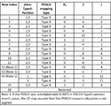
図19は、基地局の観点から見た例示的な一実施形態によるフローチャート1900である。ステップ1905では、基地局は、PDSCHのための時間領域リソース割り当てテーブルでUEを設定する。ステップ1910では、基地局は、シンボルを指示し、時間領域リソース割り当てテーブル内の少なくとも1つのエントリは、そのシンボルよりも早い開始シンボルに関連付けられ、そのシンボルは、PDSCHの時間領域割り当てを制限する。
FIG. 19 is a
一実施形態では、基地局は、UEからシンボルに関する提案を受信することができる。そのシンボルは、PDSCHの時間領域割り当てを制限することができる。そのシンボルは、UEがDCI受信および/またはDCI復号を完了するのに必要な時間に従って、あるいはUEがPDSCH受信を準備するのに必要な時間に従って決定され得る。そのシンボルは、帯域幅部分に対するものとすることができる。基地局は、少なくとも1つのエントリでUEをスケジュールすることを禁止する。 In one embodiment, the base station can receive proposals for symbols from the UE. The symbol can limit the PDSCH time domain allocation. The symbol may be determined according to the time required for the UE to complete DCI reception and / or DCI decoding, or according to the time required for the UE to prepare PDSCH reception. The symbol can be for the bandwidth portion. The base station prohibits scheduling the UE with at least one entry.
図3および図4に戻って参照すると、基地局の例示的の一実施形態において、デバイス300は、メモリ310に記憶されたプログラムコード312を含む。CPU308は、プログラムコード312を実行して、基地局が、(i)PDSCHのための時間領域リソース割り当てテーブルでUEを設定することと、(ii)シンボルを指示し、時間領域リソース割り当てテーブル内の少なくとも1つのエントリは、そのシンボルよりも早い開始シンボルと関連付けられ、そのシンボルは、PDSCHの時間領域割り当てを制限する、指示することと、を可能にすることができる。さらに、CPU308は、プログラムコード312を実行して、本明細書に記載の上述のアクションおよびステップまたはその他のすべてを実行することができる。
With reference back to FIGS. 3 and 4, in one exemplary embodiment of the base station, the
以上、本開示の種々の態様を説明した。当然のことながら、本明細書の教示内容を多種多様な形態で具現化することができ、本明細書に開示されている如何なる特定の構造、機能、または両者も代表的なものに過ぎない。本明細書の教示内容に基づいて、当業者には当然のことながら、本明細書に開示される態様は、他の如何なる態様からも独立に実装されることができ、これら態様のうちの2つ以上を種々組み合わせることができる。例えば、本明細書に記載された態様のうちの任意の数の態様を用いて、装置を実装することができ、方法を実現することができる。追加的に、本明細書に記載された態様のうちの1つ以上の追加または代替で、他の構造、機能、または構造と機能を用いて、このような装置を実装することができ、このような方法を実現することができる。上記概念の一部の一例として、いくつかの態様においては、パルス繰り返し周波数に基づいて、同時チャネルを確立することができる。いくつかの態様においては、パルス位置またはオフセットに基づいて、同時チャネルを確立することができる。いくつかの態様においては、時間ホッピングシーケンスに基づいて、同時チャネルを確立することができる。いくつかの態様においては、パルス繰り返し周波数、パルス位置またはオフセットおよび時間ホッピングシーケンスに基づいて、同時チャネルを確立することができる。
The various aspects of the present disclosure have been described above. Of course, the teachings of this specification can be embodied in a wide variety of forms, and any particular structure, function, or both disclosed herein is representative. Based on the teachings of this specification, those skilled in the art will, of course, be able to implement the embodiments disclosed herein independently of any other embodiment, and two of these embodiments. One or more can be combined in various ways. For example, any number of aspects described herein can be used to implement the device and implement methods. Additionally, in addition or alternative to one or more of the aspects described herein, other structures, functions, or structures and functions may be used to implement such devices. Such a method can be realized. As an example of some of the above concepts, in some embodiments, simultaneous channels can be established based on the pulse repetition frequency. In some embodiments, simultaneous channels can be established based on pulse position or offset. In some embodiments, simultaneous channels can be established based on a time hopping sequence. In some embodiments, simultaneous channels can be established based on pulse repetition frequency, pulse position or offset and time hopping sequence.
当業者であれば、多様な異なるテクノロジおよび技術のいずれかを使用して、情報および信号を表わしてよいを理解するであろう。例えば、上記説明全体で言及されることがあるデータ、命令、コマンド、情報、信号、ビット、シンボル、およびチップは、電圧、電流、電磁波、磁場若しくは粒子、光場若しくは粒子、またはこれらの任意の組み合わせによって表わしてよい。 Those skilled in the art will understand that information and signals may be represented using any of a wide variety of different technologies and techniques. For example, data, instructions, commands, information, signals, bits, symbols, and chips that may be referred to throughout the above description may be voltage, current, electromagnetic waves, magnetic fields or particles, light fields or particles, or any of these. It may be represented by a combination.
さらに、当業者には当然のことながら、本明細書に開示された態様に関連して説明した種々の例示的な論理ブロック、モジュール、プロセッサ、手段、回路、およびアルゴリズムステップは、電子的ハードウェア(例えば、ソースコーディングまたはその他何らかの技術を用いて設計することがあるディジタル実装、アナログ実装、またはこれら2つの組み合わせ)、命令を含む種々の形態のプログラム若しくは設計コード(本明細書においては便宜上、「ソフトウェア」または「ソフトウェアモジュール」と称されることがある)、または両者の組み合わせとして実装されてよい。このハードウェアおよびソフトウェアの互換性を明確に示すため、種々の例示的な構成要素、ブロック、モジュール、回路、およびステップを、概略的にそれぞれの機能の側面から上述した。そのような機能がハードウェアとして実装されるか、ソフトウェアとして実装されるかは、特定用途およびシステム全体に課される設計上の制約によって決まる。当業者であれば、特定各用途に対して、説明した機能を様々なやり方で実装してもよいが、そのような実装の決定は、本開示の範囲からの逸脱の原因として解釈されるべきではない。 Moreover, as a matter of course to those skilled in the art, the various exemplary logical blocks, modules, processors, means, circuits, and algorithm steps described in connection with the embodiments disclosed herein are electronic hardware. Various forms of programming or design code, including (eg, digital implementations, analog implementations, or a combination of the two, which may be designed using source coding or some other technique), instructions (in the present specification, for convenience, ". It may be implemented as "software" or "software module"), or a combination of both. To articulate this hardware and software compatibility, various exemplary components, blocks, modules, circuits, and steps have been outlined above in terms of their respective functions. Whether such functionality is implemented as hardware or software depends on the specific application and design constraints placed on the entire system. Those skilled in the art may implement the described functionality in various ways for each particular application, but decisions on such implementation should be construed as a cause of deviation from the scope of this disclosure. is not it.
追加的に、本明細書に開示される態様に関連して説明した種々の例示的な論理ブロック、モジュール、および回路は、集積回路(「IC」)、アクセス端末、またはアクセスポイント内で実装される、あるいはこれらによって実行されてよい。ICとしては、汎用プロセッサ、ディジタルシグナルプロセッサ(DSP)、特定用途向け集積回路(ASIC)、フィールドプログラマブルゲートアレイ(FPGA)、その他プログラマブル論理デバイス、ディスクリートゲート若しくはトランジスタロジック、ディスクリートハードウェアコンポーネント、電気部品、光学部品、機械部品、または本明細書で説明した機能を実行するように設計されたこれらの任意の組み合わせを含み、IC内、IC外、またはその両方に存在するコードまたは命令を実行してよい。汎用プロセッサは、マイクロプロセッサとしてよいが、代替として、プロセッサは、従来の任意のプロセッサ、コントローラ、マイクロコントローラ、または状態機械としてよい。また、プロセッサは、DSPとマイクロプロセッサとの組み合わせ、複数のマイクロプロセッサ、DSPコアと協働する1つ以上のマイクロプロセッサ、またはその他任意のこのような構成である、コンピュータデバイスの組み合わせとして実装されてよい。 Additionally, the various exemplary logic blocks, modules, and circuits described in connection with aspects disclosed herein are implemented within an integrated circuit (“IC”), access terminal, or access point. Or may be performed by these. ICs include general-purpose processors, digital signal processors (DSPs), application-specific integrated circuits (ASICs), field programmable gate arrays (FPGAs), other programmable logic devices, discrete gates or transistor logic, discrete hardware components, electrical components, etc. It may execute code or instructions that are present in or outside the IC, including optical components, mechanical components, or any combination of these designed to perform the functions described herein. .. The general purpose processor may be a microprocessor, but as an alternative, the processor may be any conventional processor, controller, microcontroller, or state machine. Processors are also implemented as a combination of DSPs and microprocessors, multiple microprocessors, one or more microprocessors that work with a DSP core, or any other combination of computer devices in such a configuration. good.
任意の開示プロセスにおけるステップの如何なる特定の順序または階層は、実例的な手法の一例であることが了解される。設計の選好に基づいて、プロセスにおけるステップの特定の順序または階層を、本開示の範囲内に留まりつつ、再構成してよいことが了解される。添付の方法の請求項は、種々のステップの要素を実例的な順序で示しており、提示の特定順序または階層に限定されることを意図していない。 It is understood that any particular sequence or hierarchy of steps in any disclosure process is an example of an exemplary approach. It is understood that, based on design preferences, the particular order or hierarchy of steps in the process may be reconstructed while remaining within the scope of the present disclosure. The accompanying method claims show the elements of the various steps in an exemplary order and are not intended to be limited to a particular order or hierarchy of presentations.
本明細書に開示される態様に関連して記載された方法またはアルゴリズムのステップを、ハードウェアにおいて直接具現化してよく、プロセッサにより実行されるソフトウェアモジュールにおいて具現化してよく、これら2つの組み合わせにおいて具現化してよい。(例えば、実行可能な命令および関連するデータを含む)ソフトウェアモジュールおよび他のデータは、RAMメモリ、フラッシュメモリ、ROMメモリ、EPROMメモリ、EEPROMメモリ、レジスタ、ハードディスク、リムバーブルディスク、CD−ROM等のデータメモリ、または当技術分野において知られているその他任意の形態のコンピュータ可読記憶媒体に存在してよい。実例的な記憶媒体がコンピュータ/プロセッサ(本明細書においては便宜上、「プロセッサ」と称されることがある)等の機械に結合されてよい、このようなプロセッサは、記憶媒体からの情報(例えば、コード)の読み出しおよび記憶媒体への情報の書き込みが可能である。実例的な記憶媒体は、プロセッサと一体化されてよい。プロセッサおよび記憶媒体は、ASICに存在してよい。ASICは、ユーザ機器に存在していてもよい。代替として、プロセッサおよび記憶媒体は、ディスクリートコンポーネントとしてユーザ機器に存在してよい。さらに、いくつかの態様においては、任意の適当なコンピュータプログラム製品が、本開示の態様のうちの1つ以上に関連するコードを含むコンピュータ可読媒体を含んでもよい。いくつかの態様において、コンピュータプログラム製品は、パッケージング材料を含んでよい。 The steps of the method or algorithm described in relation to the aspects disclosed herein may be embodied directly in hardware, in a software module executed by a processor, or in a combination of the two. It may be changed. Software modules and other data (including, for example, executable instructions and related data) include RAM memory, flash memory, ROM memory, EPROM memory, EEPROM memory, registers, hard disks, removable disks, CD-ROMs, etc. It may reside in data memory, or any other form of computer-readable storage medium known in the art. An exemplary storage medium may be coupled to a machine such as a computer / processor (sometimes referred to herein as a "processor" for convenience), such a processor being information from the storage medium (eg, "processor"). , Code) can be read and information can be written to the storage medium. The exemplary storage medium may be integrated with the processor. The processor and storage medium may be present in the ASIC. The ASIC may be present in the user equipment. Alternatively, the processor and storage medium may be present in the user equipment as discrete components. Further, in some embodiments, any suitable computer program product may include a computer-readable medium containing the code associated with one or more of the aspects of the present disclosure. In some embodiments, the computer program product may include packaging material.
以上、種々の態様に関連して本発明を説明したが、本発明は、さらに改良可能であることが了解される。本願は、概して本発明の原理に従うと共に、本発明が関係する技術分野における既知で慣習的な実施となるような本開示からの逸脱を含む本発明の任意の変形、使用、または適応を網羅することを意図している。 Although the present invention has been described above in relation to various aspects, it is understood that the present invention can be further improved. The present application generally follows the principles of the invention and covers any modifications, uses, or applications of the invention, including deviations from the present disclosure that would be known and customary practices in the art in which the invention relates. Is intended to be.
Claims (26)
PDSCH(物理下りリンク共有チャネル)のための時間領域リソース割り当てテーブルでUE(ユーザ機器)を設定することと、
前記UEに、PDSCHの開始シンボルと対応するDCI(下りリンク制御情報)の間の第3の持続時間が、第1の持続時間より短くないことを通知する、前記第1の持続時間の指示を送信することであって、前記PDSCHのための前記時間領域リソース割り当てテーブル内の少なくとも1つのエントリは、第2の持続時間に関連付けられ、前記第1の持続時間は前記第2の持続時間よりも長い、送信することと、
前記少なくとも1つのエントリに関連付けられた前記第2の持続時間が前記第1の持続時間よりも短いため、前記少なくとも1つのエントリで前記UEをスケジュールすることを禁止することと、を含む方法。 It ’s a method for base stations,
Setting the UE (user equipment) in the time domain resource allocation table for PDSCH (Physical Downlink Shared Channel)
The UE is instructed of the first duration to notify the UE that the third duration between the PDSCH start symbol and the corresponding DCI (downlink control information) is not shorter than the first duration. To transmit, at least one entry in the time region resource allocation table for the PDSCH is associated with a second duration, the first duration being greater than the second duration. Long, send and
A method comprising prohibiting scheduling the UE with the at least one entry because the second duration associated with the at least one entry is shorter than the first duration.
PDSCH(物理下りリンク共有チャネル)のための時間領域リソース割り当てテーブルの設定を受信することと、
PDSCHの開始シンボルと対応するDCI(下りリンク制御情報)の間の第3の持続時間が、第1の持続時間より短くないことを通知する、前記第1の持続時間の指示を受信することであって、前記時間領域リソース割り当てテーブル内の少なくとも1つのエントリが第2の持続時間に関連付けられ、前記第1の持続時間は前記第2の持続時間よりも長い、受信することと、を含み、
前記指示は、DCI(下りリンク制御情報)によって示される時間領域リソース割り当ての最も早い開始シンボルを当該UEに通知することであって、前記最も早い開始シンボルと前記対応するDCIの間の持続時間が前記第1の持続時間よりも短くなく、前記UEは、前記最も早い開始シンボルより前のPDSCHを受信またはバッファせず、前記少なくとも1つのエントリは、前記最も早い開始シンボルより前のPDSCH開始を割り当てる、決定することと、を含む方法。 A method for UEs (user equipment)
Receiving time domain resource allocation table settings for PDSCH (Physical Downlink Shared Channel)
By receiving the first duration instruction, notifying that the third duration between the PDSCH start symbol and the corresponding DCI (downlink control information) is not shorter than the first duration. The first duration is longer than the second duration, including receiving, where at least one entry in the time region resource allocation table is associated with a second duration.
The instruction is to notify the UE of the earliest start symbol of time domain resource allocation indicated by DCI (downlink control information), the duration between the earliest start symbol and the corresponding DCI. Not shorter than the first duration, the UE does not receive or buffer the PDSCH before the earliest start symbol, and the at least one entry allocates a PDSCH start before the earliest start symbol. , To determine, and how to include.
Applications Claiming Priority (2)
| Application Number | Priority Date | Filing Date | Title |
|---|---|---|---|
| US201862711281P | 2018-07-27 | 2018-07-27 | |
| US62/711,281 | 2018-07-27 |
Publications (3)
| Publication Number | Publication Date |
|---|---|
| JP2020022159A JP2020022159A (en) | 2020-02-06 |
| JP2020022159A5 JP2020022159A5 (en) | 2020-08-06 |
| JP6913129B2 true JP6913129B2 (en) | 2021-08-04 |
Family
ID=67253681
Family Applications (1)
| Application Number | Title | Priority Date | Filing Date |
|---|---|---|---|
| JP2019128448A Active JP6913129B2 (en) | 2018-07-27 | 2019-07-10 | Methods and devices for power saving methods when receiving PDSCH (Physical Downlink Shared Channel) in wireless communication systems |
Country Status (6)
| Country | Link |
|---|---|
| US (2) | US10820269B2 (en) |
| EP (1) | EP3599733B1 (en) |
| JP (1) | JP6913129B2 (en) |
| KR (1) | KR102202779B1 (en) |
| CN (1) | CN110784914B (en) |
| TW (1) | TWI713393B (en) |
Families Citing this family (32)
| Publication number | Priority date | Publication date | Assignee | Title |
|---|---|---|---|---|
| EP2822202B1 (en) * | 2012-02-29 | 2018-01-10 | Samsung Electronics Co., Ltd. | Method and apparatus for transceiving channel related to terminal that supports half duplex transmission in mobile communication system |
| US11671519B2 (en) * | 2018-02-14 | 2023-06-06 | Lenovo (Singapore) Pte. Ltd. | Determining linked bandwidth parts |
| WO2020027587A1 (en) * | 2018-07-31 | 2020-02-06 | 엘지전자 주식회사 | Method for allocating resource, for transmitting/receiving data in wireless communication system, and device therefor |
| US20210314984A1 (en) * | 2018-08-09 | 2021-10-07 | Lg Electronics Inc. | Method for transmitting and receiving signal in wireless communication system for supporting unlicensed band, and device for supporting same |
| US20210314997A1 (en) * | 2018-08-10 | 2021-10-07 | Lg Electronics Inc. | Method for monitoring scheduling information in wireless communication system, and device using method |
| US20210400699A1 (en) * | 2018-09-28 | 2021-12-23 | Telefonaktiebolaget Lm Ericsson (Publ) | Transitioning between different scheduling delay assumptions |
| EP4236178A3 (en) * | 2018-10-26 | 2023-10-11 | Telefonaktiebolaget LM Ericsson (publ) | Downlink control information (dci) size matching |
| WO2020085856A1 (en) * | 2018-10-26 | 2020-04-30 | 엘지전자 주식회사 | Method whereby terminal receives downlink signal in wireless communication system, and terminal for same |
| CN113475113A (en) * | 2018-12-21 | 2021-10-01 | 三星电子株式会社 | Method and apparatus for processing multiple active BWPs |
| CN113557767B (en) * | 2019-02-13 | 2022-09-16 | 荣耀终端有限公司 | Method and apparatus for uplink transmission in power saving mode |
| US11239939B2 (en) * | 2019-03-22 | 2022-02-01 | Samsung Electronics Co., Ltd. | Scheduling in communication systems with multiple service types |
| US11553471B2 (en) * | 2019-03-29 | 2023-01-10 | Samsung Electronics Co., Ltd. | Method and apparatus for transmitting data |
| WO2020227092A1 (en) * | 2019-05-03 | 2020-11-12 | Apple Inc. | System and method for ue processing time relaxation for multi-trp transmission |
| US11304218B2 (en) * | 2019-07-24 | 2022-04-12 | Samsung Electronics Co., Ltd. | Control signaling design for improved resource utilization |
| EP4014410A1 (en) * | 2019-08-16 | 2022-06-22 | Telefonaktiebolaget Lm Ericsson (Publ) | Dci signalling including at least one slot format indicator, sfi, field, and a frequency resource indicator field |
| US11632774B2 (en) * | 2019-10-04 | 2023-04-18 | Qualcomm Incorporated | Systems and methods for determining cancellation timeline for user equipment with mixed processing capabilities |
| US11758514B2 (en) * | 2019-12-20 | 2023-09-12 | Qualcomm Incorporated | Physical downlink control channel candidates related to physical downlink control channel repetitions |
| WO2021159510A1 (en) * | 2020-02-14 | 2021-08-19 | 富士通株式会社 | Uplink transmission method and apparatus |
| WO2021174497A1 (en) * | 2020-03-05 | 2021-09-10 | 华为技术有限公司 | Method for determining uplink bandwidth, and communication apparatus |
| WO2021179268A1 (en) * | 2020-03-12 | 2021-09-16 | 华为技术有限公司 | Communication method and apparatus |
| US20210297197A1 (en) * | 2020-03-20 | 2021-09-23 | Qualcomm Incorporated | Non-dropping rule for mini-slot based repetition |
| WO2021201299A1 (en) * | 2020-04-02 | 2021-10-07 | Sharp Kabushiki Kaisha | Terminal apparatus, base station apparatus, and communication method |
| CN113541893B (en) * | 2020-04-15 | 2022-09-30 | 北京紫光展锐通信技术有限公司 | Channel monitoring method and device |
| DE112021002457T5 (en) * | 2020-07-14 | 2023-03-30 | Intel Corporation | CONTROL CHANNEL TRANSMISSION TECHNIQUES FOR RADIOLESS OPERATION AND SCHEDULING OF DATA TRANSMISSIONS |
| WO2022086261A1 (en) * | 2020-10-22 | 2022-04-28 | 엘지전자 주식회사 | Method, user equipment, processing device, storage medium, and computer program for receiving downlink channel, and method and base station for transmitting downlink channel |
| US20220287013A1 (en) * | 2021-03-04 | 2022-09-08 | Samsung Electronics Co., Ltd. | Method and apparatus for beam indication with a dl-related dci format |
| CN116941296A (en) * | 2021-04-30 | 2023-10-24 | Oppo广东移动通信有限公司 | Uplink transmission method, terminal equipment and network equipment |
| EP4348909A1 (en) * | 2021-06-04 | 2024-04-10 | Qualcomm Incorporated | Search space sharing for cross-carrier scheduling |
| US20230049735A1 (en) * | 2021-08-12 | 2023-02-16 | Samsung Electronics Co., Ltd. | Methods and apparatus for ue power savings in initial downlink bandwidth part dedicated to redcap devices |
| WO2023101499A1 (en) * | 2021-12-03 | 2023-06-08 | 삼성전자 주식회사 | Bandwidth-based synchronization signal configuration method and apparatus |
| WO2023201745A1 (en) * | 2022-04-22 | 2023-10-26 | Zte Corporation | Method, device, and system for resource management in wireless networks |
| WO2024035244A1 (en) * | 2022-08-11 | 2024-02-15 | 엘지전자 주식회사 | Signal transmission and reception method for wireless communication and apparatus therefor |
Family Cites Families (16)
| Publication number | Priority date | Publication date | Assignee | Title |
|---|---|---|---|---|
| WO2010112086A1 (en) * | 2009-04-03 | 2010-10-07 | Nokia Siemens Networks Oy | Communication resource allocation strategy |
| WO2013009005A2 (en) * | 2011-07-14 | 2013-01-17 | 엘지전자 주식회사 | Method of allocating a resource in a wireless communication system and device for same |
| CN103650631A (en) * | 2011-09-30 | 2014-03-19 | 富士通株式会社 | Method and device for notifying physical downlink shared channel starting symbol |
| US8842760B2 (en) * | 2012-07-17 | 2014-09-23 | Broadcom Corporation | Enhanced multi user MIMO scheduling |
| EP3573301B1 (en) * | 2014-06-12 | 2021-05-26 | LG Electronics Inc. | Method and apparatus for performing blind detection in wireless communication system |
| US10756862B2 (en) * | 2015-04-10 | 2020-08-25 | Lg Electronics Inc. | Method and device for controlling transmission of sounding reference signal in wireless access system supporting machine type communication |
| TWI642313B (en) * | 2016-04-01 | 2018-11-21 | 聯發科技股份有限公司 | Method of pucch resource allocation and user equipment |
| US11477771B2 (en) * | 2016-04-05 | 2022-10-18 | Qualcomm Incorporated | Indicating start and stop symbols of PDSCH and PUSCH through PDCCH |
| US10791571B2 (en) * | 2016-04-26 | 2020-09-29 | Lg Electronics Inc. | Downlink signal receiving method and user equipment, and downlink signal transmission method and base station |
| KR102271448B1 (en) * | 2016-07-01 | 2021-07-01 | 엘지전자 주식회사 | Method for transmitting/receiving uplink signal between base station and terminal in wireless communication system, and device for supporting same |
| US11140714B2 (en) * | 2016-09-30 | 2021-10-05 | Qualcomm Incorporated | PRACH and/or SRS switching enhancements |
| US20180132229A1 (en) * | 2016-11-04 | 2018-05-10 | Mediatek Inc. | Method And Apparatus For Multiplexing Physical Uplink Control Channels In Mobile Communications |
| US10506587B2 (en) * | 2017-05-26 | 2019-12-10 | Samsung Electronics Co., Ltd. | Method and apparatus for beam indication in next generation wireless systems |
| CN117376990A (en) * | 2017-06-16 | 2024-01-09 | 韩国电子通信研究院 | Bandwidth setting method for supporting broadband carrier in communication system |
| CA3186287A1 (en) * | 2017-11-17 | 2019-05-23 | Telefonaktiebolaget Lm Ericsson (Publ) | Selection of time-domain resource allocation tables |
| US11025456B2 (en) * | 2018-01-12 | 2021-06-01 | Apple Inc. | Time domain resource allocation for mobile communication |
-
2019
- 2019-07-10 CN CN201910620839.8A patent/CN110784914B/en active Active
- 2019-07-10 US US16/507,502 patent/US10820269B2/en active Active
- 2019-07-10 TW TW108124355A patent/TWI713393B/en active
- 2019-07-10 JP JP2019128448A patent/JP6913129B2/en active Active
- 2019-07-10 KR KR1020190083130A patent/KR102202779B1/en active IP Right Grant
- 2019-07-10 EP EP19185403.3A patent/EP3599733B1/en active Active
-
2020
- 2020-09-14 US US17/020,554 patent/US20200413335A1/en not_active Abandoned
Also Published As
| Publication number | Publication date |
|---|---|
| EP3599733A1 (en) | 2020-01-29 |
| KR20200012733A (en) | 2020-02-05 |
| JP2020022159A (en) | 2020-02-06 |
| US20200413335A1 (en) | 2020-12-31 |
| CN110784914B (en) | 2023-07-18 |
| US10820269B2 (en) | 2020-10-27 |
| TWI713393B (en) | 2020-12-11 |
| KR102202779B1 (en) | 2021-01-14 |
| CN110784914A (en) | 2020-02-11 |
| TW202008820A (en) | 2020-02-16 |
| US20200037245A1 (en) | 2020-01-30 |
| EP3599733B1 (en) | 2023-11-29 |
Similar Documents
| Publication | Publication Date | Title |
|---|---|---|
| JP6913129B2 (en) | Methods and devices for power saving methods when receiving PDSCH (Physical Downlink Shared Channel) in wireless communication systems | |
| JP6821837B2 (en) | Methods and devices for random access settings in wireless communication systems | |
| US11503626B2 (en) | Method and apparatus for beam indication considering cross carrier scheduling in a wireless communication system | |
| JP6845883B2 (en) | Methods and devices for buffering downlink data in consideration of cross-carrier scheduling in wireless communication systems. | |
| US10873936B2 (en) | Method and apparatus for determining codebook size in a wireless communication system | |
| JP6756001B2 (en) | Methods and Devices for Downlink Control Information (DCI) Content Processing Considering Active Downlink (DL) Bandwidth Part (BWP) Changes in Wireless Communication Systems | |
| JP6709962B2 (en) | Deterministic behavior of user equipment for CSI/SRS reporting during DRX | |
| KR102519401B1 (en) | Method and apparatus for performing physical layer mobility procedures | |
| JP6584958B2 (en) | Terminal apparatus, base station apparatus, and communication method | |
| TWI756394B (en) | Uplink control channel configurations for wireless communications | |
| US20210337541A1 (en) | Method and apparatus for slot format determination in a wireless communication system | |
| JP2021184612A (en) | Method and apparatus for determining numerology bandwidth in wireless communication system | |
| JP2020195155A (en) | Method and apparatus for controlling channel transmission in wireless communication system | |
| AU2017264592B2 (en) | Dynamic cyclic prefix (CP) length in wireless communication | |
| WO2015137447A1 (en) | Terminal device, base station device, and communication method | |
| JP5722471B2 (en) | Method and apparatus for measuring channel state information in a wireless communication system | |
| EP3744023A1 (en) | Adaptive autonomous uplink communication design | |
| KR102254836B1 (en) | Method and apparatus for determining slot format in a wireless communication system | |
| US20220191843A1 (en) | Method for cell cyclic downlink transmission in wireless communication system and apparatus therefor | |
| RU2763997C1 (en) | Tdd dynamic uplink/downlink configuration using dci | |
| JP6508642B2 (en) | Dynamic TDD Uplink / Downlink Configuration Using DCI | |
| KR101922040B1 (en) | Data transmission method and device | |
| JP6681613B2 (en) | Dynamic TDD Uplink / Downlink Configuration Using DCI |
Legal Events
| Date | Code | Title | Description |
|---|---|---|---|
| A621 | Written request for application examination |
Free format text: JAPANESE INTERMEDIATE CODE: A621 Effective date: 20190909 |
|
| A521 | Request for written amendment filed |
Free format text: JAPANESE INTERMEDIATE CODE: A523 Effective date: 20200623 |
|
| A871 | Explanation of circumstances concerning accelerated examination |
Free format text: JAPANESE INTERMEDIATE CODE: A871 Effective date: 20200623 |
|
| A977 | Report on retrieval |
Free format text: JAPANESE INTERMEDIATE CODE: A971007 Effective date: 20200910 |
|
| A975 | Report on accelerated examination |
Free format text: JAPANESE INTERMEDIATE CODE: A971005 Effective date: 20200917 |
|
| A131 | Notification of reasons for refusal |
Free format text: JAPANESE INTERMEDIATE CODE: A131 Effective date: 20201006 |
|
| A521 | Request for written amendment filed |
Free format text: JAPANESE INTERMEDIATE CODE: A523 Effective date: 20210106 |
|
| A131 | Notification of reasons for refusal |
Free format text: JAPANESE INTERMEDIATE CODE: A131 Effective date: 20210330 |
|
| A521 | Request for written amendment filed |
Free format text: JAPANESE INTERMEDIATE CODE: A523 Effective date: 20210511 |
|
| TRDD | Decision of grant or rejection written | ||
| A01 | Written decision to grant a patent or to grant a registration (utility model) |
Free format text: JAPANESE INTERMEDIATE CODE: A01 Effective date: 20210622 |
|
| A61 | First payment of annual fees (during grant procedure) |
Free format text: JAPANESE INTERMEDIATE CODE: A61 Effective date: 20210709 |
|
| R150 | Certificate of patent or registration of utility model |
Ref document number: 6913129 Country of ref document: JP Free format text: JAPANESE INTERMEDIATE CODE: R150 |
|
| R250 | Receipt of annual fees |
Free format text: JAPANESE INTERMEDIATE CODE: R250 |