JP6912470B2 - Methods and devices for wireless communication using a security model to support multiple connection and service contexts - Google Patents
Methods and devices for wireless communication using a security model to support multiple connection and service contexts Download PDFInfo
- Publication number
- JP6912470B2 JP6912470B2 JP2018524790A JP2018524790A JP6912470B2 JP 6912470 B2 JP6912470 B2 JP 6912470B2 JP 2018524790 A JP2018524790 A JP 2018524790A JP 2018524790 A JP2018524790 A JP 2018524790A JP 6912470 B2 JP6912470 B2 JP 6912470B2
- Authority
- JP
- Japan
- Prior art keywords
- service
- context
- client device
- network
- connection
- Prior art date
- Legal status (The legal status is an assumption and is not a legal conclusion. Google has not performed a legal analysis and makes no representation as to the accuracy of the status listed.)
- Active
Links
Images


Classifications
-
- H—ELECTRICITY
- H04—ELECTRIC COMMUNICATION TECHNIQUE
- H04W—WIRELESS COMMUNICATION NETWORKS
- H04W12/00—Security arrangements; Authentication; Protecting privacy or anonymity
- H04W12/08—Access security
-
- H—ELECTRICITY
- H04—ELECTRIC COMMUNICATION TECHNIQUE
- H04W—WIRELESS COMMUNICATION NETWORKS
- H04W12/00—Security arrangements; Authentication; Protecting privacy or anonymity
- H04W12/06—Authentication
-
- H—ELECTRICITY
- H04—ELECTRIC COMMUNICATION TECHNIQUE
- H04L—TRANSMISSION OF DIGITAL INFORMATION, e.g. TELEGRAPHIC COMMUNICATION
- H04L63/00—Network architectures or network communication protocols for network security
- H04L63/04—Network architectures or network communication protocols for network security for providing a confidential data exchange among entities communicating through data packet networks
- H04L63/0428—Network architectures or network communication protocols for network security for providing a confidential data exchange among entities communicating through data packet networks wherein the data content is protected, e.g. by encrypting or encapsulating the payload
-
- H—ELECTRICITY
- H04—ELECTRIC COMMUNICATION TECHNIQUE
- H04W—WIRELESS COMMUNICATION NETWORKS
- H04W76/00—Connection management
- H04W76/10—Connection setup
-
- H—ELECTRICITY
- H04—ELECTRIC COMMUNICATION TECHNIQUE
- H04W—WIRELESS COMMUNICATION NETWORKS
- H04W76/00—Connection management
- H04W76/10—Connection setup
- H04W76/15—Setup of multiple wireless link connections
-
- H—ELECTRICITY
- H04—ELECTRIC COMMUNICATION TECHNIQUE
- H04W—WIRELESS COMMUNICATION NETWORKS
- H04W12/00—Security arrangements; Authentication; Protecting privacy or anonymity
- H04W12/60—Context-dependent security
- H04W12/69—Identity-dependent
- H04W12/71—Hardware identity
-
- H—ELECTRICITY
- H04—ELECTRIC COMMUNICATION TECHNIQUE
- H04W—WIRELESS COMMUNICATION NETWORKS
- H04W12/00—Security arrangements; Authentication; Protecting privacy or anonymity
- H04W12/60—Context-dependent security
- H04W12/69—Identity-dependent
- H04W12/72—Subscriber identity
-
- H—ELECTRICITY
- H04—ELECTRIC COMMUNICATION TECHNIQUE
- H04W—WIRELESS COMMUNICATION NETWORKS
- H04W80/00—Wireless network protocols or protocol adaptations to wireless operation
- H04W80/02—Data link layer protocols
Description
関連出願の相互参照
本出願は、2015年11月17日に米国特許商標庁に提出された仮出願第62/256,472号と、2016年2月19日に米国特許商標庁に提出された非仮出願第15/048,044号の優先権および利益を主張し、その内容全体は、以下に完全に記載されているかのように、またすべての適用可能な目的のために、参照により本明細書に組み込まれる。
Cross-reference to related applications This application is a provisional application No. 62 / 256,472 filed with the United States Patent and Trademark Office on November 17, 2015, and a non-provisional application filed with the United States Patent and Trademark Office on February 19, 2016. Claim the priority and interests of Application No. 15 / 048,044, the entire contents of which are incorporated herein by reference as if fully described below and for all applicable purposes. Is done.
以下に説明する技術は、一般に、ワイヤレス通信システムに関し、より詳細には、複数の接続およびサービスコンテキスト(connectivity and service context)をサポートするためのセキュリティモデルに関する。 The techniques described below generally relate to wireless communication systems, and more particularly to security models for supporting multiple connectivity and service contexts.
現在のワイヤレスシステムは、通常、パケット交換ドメイン内で動作する。ワイヤレスシステムのいくつかの例は、LTE(ロングタームエボリューション)、LTE-A(LTE-Advance)、およびWLAN(ワイヤレスローカルアクセスネットワーク)である。そのようなワイヤレスシステムは、通常、ユーザデバイスとネットワークの接続管理部分との間の単一の接続コンテキスト(connectivity context)を使用することによって、単一のサブスクリプションおよび/または単一の資格情報のみをサポートする。LTEの例では、ユーザ機器(UE)(ユーザデバイス)とモビリティ管理エンティティ(MME)との間で、単一の非アクセス層(NAS)コンテキストが使用され得る。LTEにおいて、NASは、LTEアクセスのためにUEとMMEとの間の非無線関連シグナリングを搬送するために使用されるプロトコルのセットである。接続コンテキストは、一般に、2つのエンティティ間(たとえば、ユーザデバイスとネットワークへのエンティティ、またはネットワークエンティティとネットワークエンティティ)の接続に関連付けられる、またはその接続を定義する情報を指す。 Today's wireless systems typically operate within a packet-switched domain. Some examples of wireless systems are LTE (Long Term Evolution), LTE-A (LTE-Advance), and WLAN (Wireless Local Access Network). Such wireless systems typically have only a single subscription and / or a single credential by using a single connectivity context between the user device and the connectivity management part of the network. Support. In the LTE example, a single non-access layer (NAS) context can be used between the user equipment (UE) (user device) and the mobility management entity (MME). In LTE, NAS is a set of protocols used to carry non-radio related signaling between UE and MME for LTE access. A connection context generally refers to information that is associated with or defines a connection between two entities (eg, an entity to a user device and a network, or a network entity and a network entity).
関連技術では、ユーザデバイス(たとえば、モバイルデバイスまたはUE)は一般に、加入者識別モジュール(SIM)カードを含む、SIMカードは、識別情報と、そのSIMカードに固有のキーと含む。ネットワークオペレータによって提供されるサービスへのサブスクリプションを利用するユーザデバイスは、SIMカードに記憶された識別情報およびキー(または認証)情報によって、無線リンクまたはネットワークとの接続を確立することができる。言い換えれば、アクセスリンクの使用と接続コンテキストの使用との間に密接な接続(たとえば、1対1の関係)が存在する。アクセスリンクの例には、セルラーネットワークの場合のユーザプレーンおよび無線リソース制御(RRC)またはメディアアクセス制御(MAC)信号接続が含まれる。LTEの例では、無線リンクの確立にはEMM(進化型パケットシステム(EPS)モビリティ管理)コンテキストとESM(EPSセッション管理)コンテキストが関係する。さらに、UEがネットワークに接続する場合、LTEの例では、モビリティ管理エンティティ(MME)において、モビリティ管理コンテキスト(EMMコンテキスト)およびセッション管理コンテキスト(ESMコンテキスト)が作成される。EMMコンテキストとESMコンテキストの両方は、SIMカードに記憶された単一の資格情報(たとえば、SIM資格情報)に関連付けられる。資格情報は、MMEが、UEが要求された接続を確立するために認証され得るかどうかを決定することを可能にする。この場合、MMEは、利用可能なすべてのサービスに対して、1つのプロバイダとの1つの認証ポイントを提供する。コンテキストとSIM資格情報とのペアの間には1対1の関連がある。したがって、関連コンテキストのペアはSIM資格情報に密接に結合されていると言うことができる。 In related technology, a user device (eg, a mobile device or UE) generally includes a subscriber identification module (SIM) card, which includes identification information and a key unique to that SIM card. User devices that utilize subscriptions to services provided by network operators can establish a wireless link or network connection with identification and key (or authentication) information stored on the SIM card. In other words, there is a close connection (eg, a one-to-one relationship) between the use of access links and the use of connection contexts. Examples of access links include user plane and radio resource control (RRC) or media access control (MAC) signal connections for cellular networks. In the LTE example, establishing a wireless link involves the EMM (Evolved Packet System (EPS) Mobility Management) context and the ESM (EPS Session Management) context. In addition, when the UE connects to the network, in the LTE example, the mobility management entity (MME) creates a mobility management context (EMM context) and a session management context (ESM context). Both the EMM context and the ESM context are associated with a single credential stored on the SIM card (for example, SIM credential). Credentials allow the MME to determine if the UE can be authenticated to establish the requested connection. In this case, MME provides one authentication point with one provider for all available services. There is a one-to-one association between the context and the SIM credential pair. Therefore, it can be said that the related context pair is tightly bound to the SIM credentials.
以下は、そのような態様の基本的な理解を提供するために、本開示の1つまたは複数の態様の簡略化された概要を提示する。本概要は、本開示のすべての企図される特徴の広範な概観ではなく、本開示のすべての態様の主要または重要な要素を識別するものでも、本開示のいずれかまたはすべての態様の範囲を定めるものでもない。その唯一の目的は、後で提示されるより詳細な説明の前置きとして、本開示の1つまたは複数の態様のいくつかの概念を簡略化した形で提示することである。 The following provides a simplified overview of one or more aspects of the present disclosure to provide a basic understanding of such aspects. This overview is not an extensive overview of all the intended features of the present disclosure, but rather the scope of any or all aspects of the disclosure, even if it identifies the key or important elements of all aspects of the disclosure. It is not something to define. Its sole purpose is to present in a simplified form some concepts of one or more aspects of the present disclosure as a prelude to a more detailed description presented later.
本開示の態様は、複数の接続およびサービスコンテキストをサポートするためのセキュリティモデルを開示する。接続コンテキストと複数のサービスコンテキストを確立するために、異なる資格情報が使用され得る。 Aspects of this disclosure disclose a security model for supporting multiple connection and service contexts. Different credentials can be used to establish a connection context and multiple service contexts.
本開示の一態様は、ワイヤレス通信ネットワークにおいてクライアントデバイスを動作させる方法を提供する。この方法によれば、クライアントデバイスは、第1の資格情報に基づいて接続ネットワークとの接続を確立する。クライアントデバイスは、接続に対応する接続コンテキストを確立する。クライアントデバイスは、接続ネットワークに関連付けられる1つまたは複数のサービスネットワークを識別する。クライアントデバイスは、確立された接続を利用して1つまたは複数のサービスネットワークとの1つまたは複数のサービス接続を確立し、1つまたは複数のサービス接続は、それぞれの第2の資格情報を使用して確立される。クライアントデバイスは、サービス接続にそれぞれ対応する1つまたは複数のサービスコンテキストを確立する。1つまたは複数のサービスコンテキストは、それぞれ異なるセキュリティコンテキストを含む。セキュリティコンテキストの各々は、両方とも同じ第2の資格情報に対応する、非アクセス層(NAS)セキュリティコンテキストおよびアクセス層(AS)セキュリティコンテキストを含む。 One aspect of the disclosure provides a method of operating a client device in a wireless communication network. According to this method, the client device establishes a connection with the connection network based on the first credential. The client device establishes the connection context that corresponds to the connection. The client device identifies one or more service networks associated with the connected network. The client device utilizes the established connection to establish one or more service connections with one or more service networks, and one or more service connections use their respective second credentials. Is established. The client device establishes one or more service contexts, each corresponding to a service connection. One or more service contexts each contain a different security context. Each of the security contexts includes a non-access layer (NAS) security context and an access layer (AS) security context, both of which correspond to the same second credential.
本開示の一態様は、接続ネットワークのネットワークノードを動作させる方法を提供する。この方法によれば、ネットワークノードは、接続資格情報に基づいてクライアントデバイスとの第1の接続を確立する。ネットワークノードは、第1の接続に対応する接続コンテキストを確立する。ネットワークノードは、クライアントデバイスから、1つまたは複数のサービスネットワークとの接続を確立する要求を受信する。ネットワークノードは、ネットワークノードをプロキシとして利用して、クライアントデバイス用のサービスネットワークとの複数の第2の接続をそれぞれ確立する。ネットワークノードは、ホストモビリティ管理エンティティ(HMME)を含む。 One aspect of the present disclosure provides a method of operating a network node of a connected network. According to this method, the network node establishes a first connection with the client device based on the connection credentials. The network node establishes a connection context that corresponds to the first connection. The network node receives a request from the client device to establish a connection with one or more service networks. The network node uses the network node as a proxy to establish multiple second connections to the service network for the client device, respectively. The network node contains the Host Mobility Management Entity (HMME).
本開示の一態様は、サービスネットワークのネットワークノードを動作させる方法を提供する。この方法によれば、ネットワークノードは、クライアントデバイスから接続を確立する要求を受信する。ネットワークノードは、接続ネットワークのネットワークノードを介してクライアントデバイスとの接続を確立する。接続ネットワークのネットワークノードは、ホストモビリティ管理エンティティ(HMME)を含む。ネットワークノードは、接続に対応するサービスコンテキストを確立し、サービスコンテキストはセキュリティコンテキストに関連付けられる。 One aspect of the present disclosure provides a method of operating a network node of a service network. According to this method, the network node receives a request from the client device to establish a connection. The network node establishes a connection with the client device through the network node of the connected network. The network node of the connected network contains the Host Mobility Management Entity (HMME). The network node establishes a service context that corresponds to the connection, and the service context is associated with the security context.
本開示の一態様は、ワイヤレス通信ネットワークにおけるクライアントデバイスを提供する。クライアントデバイスは、コンピュータ実行可能コードが記憶されたメモリと、接続ネットワークと通信するように構成された通信インターフェースと、メモリおよび通信インターフェースに動作可能に結合されたプロセッサとを含む。プロセッサは、コンピュータ実行可能コードによって、第1の資格情報に基づいて接続ネットワークとの接続を確立するように構成される。プロセッサは、接続に対応する接続コンテキストを確立するようにさらに構成される。プロセッサは、接続ネットワークに関連付けられる1つまたは複数のサービスネットワークを識別するようにさらに構成される。プロセッサは、確立された接続を利用して1つまたは複数のサービスネットワークとの1つまたは複数のサービス接続を確立するようにさらに構成される。1つまたは複数のサービス接続は、それぞれの第2の資格情報を使用して確立される。プロセッサは、サービス接続にそれぞれ対応する1つまたは複数のサービスコンテキストを確立するようにさらに構成される。1つまたは複数のサービスコンテキストは、それぞれ異なるセキュリティコンテキストを含む。セキュリティコンテキストの各々は、両方とも同じ第2の資格情報に対応する、非アクセス層(NAS)セキュリティコンテキストおよびアクセス層(AS)セキュリティコンテキストを含む。 One aspect of the disclosure provides a client device in a wireless communication network. The client device includes a memory in which the computer executable code is stored, a communication interface configured to communicate with the connected network, and a processor operably coupled to the memory and the communication interface. The processor is configured by computer executable code to establish a connection with the connection network based on the first credential. The processor is further configured to establish a connection context corresponding to the connection. The processor is further configured to identify one or more service networks associated with the connected network. The processor is further configured to take advantage of the established connections to establish one or more service connections with one or more service networks. One or more service connections are established using their respective second credentials. The processor is further configured to establish one or more service contexts, each corresponding to a service connection. One or more service contexts each contain a different security context. Each of the security contexts includes a non-access layer (NAS) security context and an access layer (AS) security context, both of which correspond to the same second credential.
本開示の一態様は、接続ネットワークのネットワークノードを提供する。ネットワークノードは、コンピュータ実行可能コードが記憶されたメモリと、クライアントデバイスと通信するように構成された通信インターフェースと、メモリおよび通信インターフェースに動作可能に結合されたプロセッサとを含む。プロセッサは、コンピュータ実行可能コードによって、接続資格情報に基づいてクライアントデバイスとの第1の接続を確立するように構成される。プロセッサは、第1の接続に対応する接続コンテキストを確立するようにさらに構成される。プロセッサは、クライアントデバイスから、1つまたは複数のサービスネットワークとのサービス接続を確立する要求を受信するようにさらに構成される。プロセッサは、ネットワークノードをプロキシとして利用して、クライアントデバイス用のサービスネットワークとの複数の第2の接続をそれぞれ確立するようにさらに構成される。ネットワークノードは、ホストモビリティ管理エンティティ(HMME)を含む。 One aspect of the disclosure provides a network node for a connected network. A network node includes a memory in which computer executable code is stored, a communication interface configured to communicate with a client device, and a processor operably coupled to the memory and communication interface. The processor is configured by computer executable code to establish a first connection with the client device based on the connection credentials. The processor is further configured to establish a connection context corresponding to the first connection. The processor is further configured to receive requests from client devices to establish a service connection with one or more service networks. The processor is further configured to utilize the network node as a proxy to establish multiple second connections, respectively, to the service network for the client device. The network node contains the Host Mobility Management Entity (HMME).
本開示の一態様は、サービスネットワークのネットワークノードを提供する。ネットワークノードは、コンピュータ実行可能コードが記憶されたメモリと、クライアントデバイスと通信するように構成された通信インターフェースと、メモリおよび通信インターフェースに動作可能に結合されたプロセッサとを含む。プロセッサは、実行可能コードによって、クライアントデバイスから、接続を確立する要求を受信するように構成される。プロセッサは、接続ネットワークのネットワークノードを介してクライアントデバイスとの接続を確立するようにさらに構成される。接続ネットワークのネットワークノードは、ホストモビリティ管理エンティティ(HMME)を含む。プロセッサは、接続に対応するサービスコンテキストを確立するようにさらに構成され、サービスコンテキストはセキュリティコンテキストに関連付けられる。 One aspect of the disclosure provides a network node for a service network. A network node includes a memory in which computer executable code is stored, a communication interface configured to communicate with a client device, and a processor operably coupled to the memory and communication interface. The processor is configured by the executable code to receive a request from the client device to establish a connection. The processor is further configured to establish a connection with the client device through the network nodes of the connected network. The network node of the connected network contains the Host Mobility Management Entity (HMME). The processor is further configured to establish a service context that corresponds to the connection, and the service context is associated with the security context.
本発明のこれらおよび他の態様は、以下の詳細な説明を検討することにより、より完全に理解されるであろう。添付の図とともに本発明の特定の例示的な実施形態の以下の説明を検討すれば、本発明の他の態様、特徴、および実施形態が当業者に明らかとなろう。本発明の特徴について、以下のいくつかの実施形態および図に対して説明する場合があるが、本発明のすべての実施形態は、本明細書で説明する有利な特徴のうちの1つまたは複数を含むことができる。言い換えれば、1つまたは複数の実施形態は、ある有利な特徴を有するものとして説明され得るが、本明細書で論じた本発明の様々な実施形態に従ってそのような特徴のうちの1つまたは複数も使用され得る。同様に、例示的実施形態がデバイス実施形態、システム実施形態、または方法実施形態として以下で論じられ得るが、そのような例示的実施形態は、様々なデバイス、システム、および方法として実装され得ることを理解されたい。 These and other aspects of the invention will be more fully understood by reviewing the detailed description below. Other embodiments, features, and embodiments of the invention will be apparent to those skilled in the art by examining the following description of certain exemplary embodiments of the invention with the accompanying figures. Features of the invention may be described with respect to some of the following embodiments and figures, but all embodiments of the invention may be one or more of the advantageous features described herein. Can be included. In other words, one or more embodiments may be described as having certain advantageous features, but one or more of such features according to the various embodiments of the invention discussed herein. Can also be used. Similarly, exemplary embodiments may be discussed below as device embodiments, system embodiments, or method embodiments, but such exemplary embodiments may be implemented as various devices, systems, and methods. I want you to understand.
添付の図面に関連して以下に述べる本発明を実施するための形態は、様々な構成の説明として意図されており、本明細書に記載された概念が実践され得る唯一の構成を表すことが意図されるものではない。本発明を実施するための形態は、様々な概念の完全な理解を提供するための具体的な細部を含む。しかし、当業者には、これらの概念が、これらの具体的な細部なしでも実践され得ることが明らかであろう。いくつかの例では、よく知られている構造および構成要素は、そのような概念を不明瞭にすることを避けるためにブロック図形式で示される。 The embodiments described below in connection with the accompanying drawings are intended as a description of various configurations and may represent the only configuration in which the concepts described herein can be practiced. Not intended. The embodiments for carrying out the present invention include specific details to provide a complete understanding of various concepts. However, it will be apparent to those skilled in the art that these concepts can be practiced without these specific details. In some examples, well-known structures and components are shown in block diagram format to avoid obscuring such concepts.
本開示の態様は、ネットワーク接続を確立するために単一の接続コンテキストを共有しながら、複数の接続およびサービスコンテキストを可能にするためのセキュリティモデルを提供する。ネットワーク接続は、単一の無線またはワイヤレスリンクを含み得、複数の異なるサービスコンテキストおよびセキュリティコンテキストを使用する複数のサービス接続をサポートし得る。単一の無線またはワイヤレスリンクは、単一の接続コンテキストに対応する1つまたは複数のワイヤレスチャネル、周波数、または搬送波を含み得る。一般に、コンテキスト(たとえば、接続コンテキスト、サービスコンテキスト、セキュリティコンテキスト)は、2つ以上のエンティティ間に確立された接続、サービス、またはセキュリティを記述する情報のセットである。本開示の一態様では、接続コンテキストは、進化型パケットシステム(EPS)モビリティ管理(EMM)コンテキスト、またはEMMコンテキストとEPSセッション管理(ESM)コンテキストの両方を含む。 Aspects of the present disclosure provide a security model for enabling multiple connection and service contexts while sharing a single connection context to establish a network connection. The network connection may include a single wireless or wireless link and may support multiple service connections using multiple different service and security contexts. A single radio or wireless link may include one or more wireless channels, frequencies, or carriers that correspond to a single connection context. In general, a context (eg, connection context, service context, security context) is a set of information that describes a connection, service, or security established between two or more entities. In one aspect of the disclosure, the connection context includes an evolved packet system (EPS) mobility management (EMM) context, or both an EMM context and an EPS session management (ESM) context.
本開示の一態様では、無線リソース制御(RRC)リンクまたはメディアアクセス制御(MAC)リンクが、単一の接続コンテキスト(たとえば、EMMコンテキスト)に基づいて、クライアントデバイス(たとえば、UE)と無線アクセスネットワーク(RAN)との間に確立され得る。一例では、RANは、セルラーRAN、またはWi-Fiアクセスポイントから構成される無線ネットワーク、またはセルラー無線とWi-Fi無線の組合せであり得る。別の例では、RANは、ライセンスされたおよび/またはライセンスされていないスペクトルにおいて動作し、共通無線リソース制御(RRC)メカニズムまたはメディアアクセス制御(MAC)メカニズムによって制御される、1つまたは複数の無線アクセスノードを有し得る。様々な例では、RRCは、セルラーRRC、セルラーRRM(無線リソース管理)、メディアアクセス制御(MAC)、あるいは上位レイヤシグナリングおよびユーザデータの転送のための無線リソースの確立を含む、1つまたは複数のリンクを介した無線リソースへのアクセスを制御するための任意の他のシグナリングメカニズムを含み得る。 In one aspect of the disclosure, a radio resource control (RRC) link or media access control (MAC) link is based on a single connection context (eg, EMM context) with a client device (eg, UE) and a radio access network. Can be established with (RAN). In one example, the RAN can be a cellular RAN, or a wireless network consisting of Wi-Fi access points, or a combination of cellular and Wi-Fi radios. In another example, the RAN operates in a licensed and / or unlicensed spectrum and is controlled by a common radio resource control (RRC) or media access control (MAC) mechanism, one or more radios. It may have an access node. In various examples, the RRC may be one or more, including cellular RRC, cellular RRM (radio resource management), media access control (MAC), or establishing radio resources for higher layer signaling and transfer of user data. It may include any other signaling mechanism for controlling access to radio resources over the link.
単一の接続コンテキスト(たとえば、EMMコンテキスト)が確立された後、クライアントデバイスは、単一のリンクを介して同時または並列サービス接続を確立するために、異なるセキュリティコンテキストによって保護された複数の異なるサービスコンテキストを使用し得る。一例では、サービスコンテキストはESMコンテキストを含む。このようにして、共有された単一の接続コンテキストは、より低いレベルの無線リンク接続に使用され、2つ以上のサービスコンテキストは、無線リンクを介してたとえばサービスプロバイダとのサービス接続を確立するために使用される。本開示の態様は、RANへの単一のリンクまたは接続を共有しながらサービス接続を保護するためのセキュリティモデルを提供する。 After a single connection context (for example, an EMM context) is established, the client device has multiple different services protected by different security contexts to establish simultaneous or parallel service connections over a single link. Context can be used. In one example, the service context includes an ESM context. In this way, a single shared connection context is used for lower level wireless link connections, and two or more service contexts are used to establish a service connection with, for example, a service provider over the wireless link. Used for. Aspects of the present disclosure provide a security model for protecting service connections while sharing a single link or connection to the RAN.
複数のサービス接続をサポートする単一の接続性接続(Connectivity Connection)
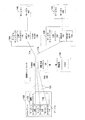
図1は、クライアントデバイス102(たとえば、UE)と無線アクセスネットワーク(RAN)120との間の単一の無線リンク101を示しており、異なるサービスコンテキスト108、110、および112に関連付けられる複数のサービス接続114、116、118をサポートしながら、クライアントデバイス102を2つ以上のサービスプロバイダ104またはプロビジョニング機能104、106に結合するために働くことができる。この特定の例では、RAN120との無線リンク101を確立するために、クライアントデバイス102において実装される単一の接続コンテキスト122が利用され得る。無線リンク101は、異なるサービスコンテキスト108、110、および112に関連付けられる複数の同時接続によって共有され得る。単一の接続コンテキスト(たとえば、EMMコンテキスト、またはEMM/ESMコンテキスト)は、セキュリティ、ベアラ管理およびデータ接続管理のためのシグナリング、ページング、モビリティなどを提供するネットワークホストモビリティ管理エンティティ(HMME)124との接続を確立するために使用される。単一の接続コンテキスト122の使用は、同じ無線リンク101を介して、対応するサービス接続114、116、118を有する複数の同時または並列サービスコンテキスト108、110、112の使用を容易にする。サービス接続の各々は、異なるセキュリティコンテキスト(たとえば、図4〜図6および図14〜図18に示される)によって保護され得る。一例では、クライアントデバイス102が3つのタイプのサブスクリプション(たとえば、3つのサービスコンテキスト)を有する場合、これは、クライアントデバイス102とRAN120との間の単一の(同じ)無線リンク101を介して、サブスクリプションおよび/またはサービスコンテキスト108、110、および112ごとに1つの、3つの同時サービス接続114、116、および118を確立する能力を可能にし得る。単一の無線リンクは、1つまたは複数の無線ベアラを含み得る。同時サービス接続114、116、および/または118のうちのいずれか1つまたは複数は、任意の所与の時間にアイドルまたはアクティブであり得る。
A single Connectivity Connection that supports multiple service connections
FIG. 1 shows a
ホストMME124(HMME)は、RAN120に論理的に近接して実装され得、接続コンテキスト(たとえば、EMMコンテキストまたはEMM/ESMコンテキスト)の確立を管理し、共有された接続コンテキスト122に基づいて無線リンク101を確立するように働く。ホストMME124は、接続コンテキストを確立するためにクライアントデバイス102を認証するように働くことができる。たとえば、ホストMME124は、クライアントデバイス102のモビリティおよび/またはセキュリティを制御するために、クライアントデバイス102とともに制御プレーン上で非アクセス層(NAS)EPSモビリティ管理(EMM)を実行し得る。ホストMME124はまた、サービス接続114、116、118をサポートまたは構成するために、クライアントデバイス102とともに制御プレーン上で非アクセス層(NAS)EPSセッション管理(ESM)を実行し得る。ホストMME124は、クライアントデバイス102に関連付けられる資格情報および加入情報に基づいて、接続コンテキスト122が確立されるべきかどうかを確かめるために、ホーム認可、認証、および課金(H-AAA)サーバ144を用いてクライアントデバイス102を認証し得る。たとえば、クライアントデバイス102は、資格情報および加入情報を記憶するためのSIMカードを有し得る。結果として、接続コンテキスト122は、クライアントデバイス102の複数のサービス接続114、116、および118によって共有され得る単一の無線リンク101を確立するために働くことができる。
Host MME124 (HMME) can be implemented in logical proximity to RAN120, manages the establishment of connection contexts (eg EMM contexts or EMM / ESM contexts), and
NASセキュリティ
本開示の一態様では、非アクセス層(NAS)モデルは、別個のEMMおよびESMコンテキストを可能にするように修正される。たとえば、HMMEを使用するEMMコンテキストが、ESMコンテキストなしで確立され得る。HMMEは、RANの近くに位置し得るコアネットワークエンティティである。クライアント(たとえば、UE)は、異なるコンテキストを確立するために異なる資格情報を有し得る。たとえば、EMMコンテキストを確立するために使用される資格情報は、ESMコンテキストを確立するために使用される資格情報とは異なる場合がある。資格情報は、クライアントが要求されたEMMコンテキストおよび/またはESMコンテキストを確立できるかどうかを決定するために、クライアントおよび/またはネットワークノードに記憶され得る情報であり得る。たとえば、ESMコンテキストを確立するためにサービス資格情報が使用されている間、EMMコンテキストを確立するために接続資格情報が使用される。異なるESMコンテキストを確立するために、異なるサービス資格情報が使用され得る。一例では、NASモデルは、同じ資格情報のセットを使用して、HMMEにおいてEMMコンテキストおよび1つまたは複数のESMコンテキスト(たとえば、図1の接続コンテキスト122およびEMM/ESMコンテキスト126)の同時の確立を可能にする。
NAS Security In one aspect of this disclosure, the non-access layer (NAS) model is modified to allow separate EMM and ESM contexts. For example, an EMM context that uses HMME can be established without an ESM context. HMME is a core network entity that can be located near RAN. The client (eg, UE) may have different credentials to establish different contexts. For example, the credentials used to establish an EMM context may differ from the credentials used to establish an ESM context. Credentials can be information that can be stored on the client and / or network node to determine if the client can establish the requested EMM context and / or ESM context. For example, while service credentials are used to establish an ESM context, connection credentials are used to establish an EMM context. Different service credentials can be used to establish different ESM contexts. In one example, the NAS model uses the same set of credentials to simultaneously establish an EMM context and one or more ESM contexts (eg,
図1を参照すると、接続コンテキスト122が確立されると(すなわち、単一の無線リンク101を介してネットワークへの接続を作成する)、クライアントデバイス102は、対応する資格情報のセット(たとえば、異なるサービス資格情報)に基づいて、異なるネットワークエンティティを有する1つまたは複数のESMコンテキストを確立し得、これによって、接続プロバイダ内の区別された接続管理エンティティによるサービスの区別化が可能になる。接続管理エンティティの一例は、サービス管理エンティティ(SME)である。
Referring to FIG. 1, once the
本開示の一態様では、RAN120は、複数のサービスプロバイダ104および106に接続され得る。たとえば、各サービスプロバイダ104、106は、サービス管理エンティティ(SME)128および130を有する接続プロバイダ、ならびに1つまたは複数のパケットデータネットワークゲートウェイ(P-GW)および1つまたは複数のサービスゲートウェイ(S-GW)132および134を含み得る。これらのSME128および130の各々は、対応するサービスAAA(認可、認証、および課金)サーバによって供給され得る資格情報および加入情報を使用して確立されたサービス接続114および116のためのそれぞれのESMコンテキスト136および138を維持し得る。たとえば、SME128および130は、サービス接続114および/または116がサービスコンテキスト108および110に関連付けられる、およびにAAAサーバ140および142よって提供される資格情報に基づいて設定されるべきかどうかを確かめるために、それぞれのサービスAAAサーバ140および142を介して、またはそれらにサポートされて、クライアントデバイス102を認証し得る。認証が成功すると、SMEは、クライアントデバイス102用のサービスコンテキスト108および110(たとえば、ESMコンテキスト)を確立することができる。対応するサービスコンテキスト(ESMコンテキスト136、138)は、SME128および130において確立され得る。
In one aspect of the disclosure, the
図1の例示的な説明において、クライアントデバイス102は、第1のサービスコンテキスト108と、第2のサービスコンテキスト110と、第3のサービスコンテキスト112とを確立している。しかしながら、任意の数のサービスコンテキストがクライアントデバイス102によって確立され得ると考えられる。
In the exemplary description of FIG. 1, the
図1において、複数のサービスコンテキスト108、110、および112が、クライアントデバイス102および複数のサービスプロバイダ(たとえば、サービスネットワーク104および/または106)によって確立され得、各サービスコンテキスト108、110、および112は、1つまたは複数の資格情報のセットに対応し得る。資格情報のセットは、他のデバイス(たとえば、ネットワークデバイス)がサービスまたは接続に対するクライアントデバイス102(またはクライアントデバイスのユーザ/加入者)を識別することを可能にする情報のセット、認証に使用されるセキュリティキーなどとして定義されることも、それを含むこともある。資格情報は、セキュリティコンテキストとして実装され得る。たとえば、クライアントデバイスに記憶された認証情報およびネットワーク側に記憶された対応する情報は、セキュリティコンテキストと呼ばれ得る。
In FIG. 1,
一例では、複数の同時サービスコンテキスト108、110、および112に基づく接続114、116、および118は、RAN120との単一の接続、たとえば、通信プロトコルスタックのレイヤ2接続(たとえば、LTEレイヤ2)上で多重化され得る。サービスコンテキスト108、110、および112は、各サービスコンテキスト108、110、および112を確立するためにクライアントデバイス102によって使用される特定の/別個の識別に基づいて区別される。たとえば、クライアントデバイス102は、ネットワークへのシグナリングまたは接続を提供し、モビリティ管理を可能にするホストMME(すなわち、少なくともEMMコンテキスト)との接続確立へのセキュリティアクセスを提供する資格情報のセットを備えることができる。そのような資格情報は、たとえば、そのまま使える(out-of-the-box)資格情報、オペレータ資格情報、または、OEM(相手先商標製品の製造会社)によって提供されクライアントデバイス102を製造するエンティティによって製造時にクライアントデバイス102にインストールされた資格情報であり得る。OEM資格情報を使用することにより、OEMが資格情報を提供し、そのような資格情報の認証をホストすることができるため、サービスプロバイダ資格情報がEMMまたは接続コンテキストではなくESMコンテキストのみを提供するために使用されるので、クライアントデバイス102は異なるサービスプロバイダをサポートすることが可能になる。第1の(EMM)コンテキスト(たとえば、接続コンテキスト)の確立のためにOEM資格情報を使用することにより、このコンテキストに関してデータトラフィックまたはメッセージが生成されないので、そのような接続を確立するための使用料または料金を負担することなく、シグナリング、モビリティ管理、セキュリティなどを提供するEMM(接続)コンテキストを確立することが可能である。
In one example,
サービス関連資格情報は、SME(サービス管理エンティティ)を有する1つまたは複数のESMコンテキスト(たとえば、サービスコンテキスト)を確立するために使用される。様々な構成において、SMEはHMMEから物理的に分離されてもよく、SME(または、SME機能のソフトウェアバージョン)は、HMMEにおいて共同配置またはホストされてもよく、またはそれらの組合せであって、一部のSMEがHMMEによって共同配置/ホストされ、他のSMEがHMMEから分離されてもよい。いくつかの例では、UEは接続資格情報を用いてESMコンテキストを確立し得る。 Service-related credentials are used to establish one or more ESM contexts (eg, service contexts) that have an SME (Service Management Entity). In various configurations, the SME may be physically separated from the HMME, and the SME (or software version of the SME function) may be co-located or hosted in the HMME, or a combination thereof. Part SMEs may be co-located / hosted by HMMEs and other SMEs may be separated from HMMEs. In some examples, the UE can use connection credentials to establish an ESM context.
ASセキュリティ
アクセス層(AS)は、RAN120を介してクライアントデバイス102(たとえば、UE)とコアネットワーク(CN)との間の活動を処理する機能層およびプロトコルのセットである。たとえば、CNは、HMME124、1つまたは複数のSME128、130、1つまたは複数のS-GW132、134、および1つまたは複数のP-GW132、134を含み得る。ASにおいて、CNとクライアントデバイス102との間に複数の無線アクセスベアラ(RAB)が確立され得る。本開示の一態様では、各RABは、異なるESMコンテキストに関連付けられてもよく、各ESMコンテキストが、仮想ESM(VESM)タグ(または識別子)によって決定されてもよい。本開示の一態様では、複数のRABが同じEMMコンテキストに関連付けられる。この場合、RAN120(たとえば、eNode BまたはeNB)は、複数のESMコンテキストの可視性を有さない。すなわち、RAN120は、ESMコンテキスト間でデータトラフィックを区別することができない。eNBはRABのセットを有し、一部はたとえば第1のESMコンテキストに対応し、一部は第2のESMコンテキストに対応し、HMMEは特定のESMコンテキストへのRABのマッピングを有する。
The AS Security Access Layer (AS) is a set of functional layers and protocols that handle activity between the client device 102 (eg, UE) and the core network (CN) via RAN120. For example, a CN may include HMME124, one or more SME128, 130, one or more S-GW132, 134, and one or more P-GW132,134. In the AS, multiple radio access bearers (RABs) can be established between the CN and the
図1において、RAN120はアクセス層内に存在するものとして示されている。しかしながら、RAN120はNAS機能も提供する。アクセス層によって提供されるサービスの中には、NASエンティティ(たとえば、クライアントデバイスとコアネットワークノード)間のNASメッセージの転送がある。NASプロトコルは、クライアントデバイスのモビリティと、クライアントデバイスとコアネットワークとの間の接続を確立し維持するための手順をサポートする。たとえば、クライアントデバイス102と、図1に示されるサービスプロバイダAのコアネットワーク(CN)および/またはサービスプロバイダBのCNとの間でNASメッセージを転送するために、NASプロトコルが使用され得る。アクセス層(AS)はNASシグナリングを転送するが、NASシグナリングはアクセス層において終了しない。本開示の一態様では、クライアントデバイス102とRAN120との間の単一の無線リンク101(たとえば、RRCリンク)は、論理的に、または仮想的に、複数のサービス接続、たとえばサービス接続114および116に分割され得る。サービス接続は、それらの対応するサービスコンテキスト(たとえば、ESMコンテキスト136および138)に関連して確立される。
In FIG. 1, RAN120 is shown as being in the access layer. However, the RAN120 also provides NAS functionality. Among the services provided by the access layer is the transfer of NAS messages between NAS entities (eg, client devices and core network nodes). The NAS protocol supports client device mobility and procedures for establishing and maintaining connectivity between client devices and core networks. For example, the NAS protocol may be used to transfer NAS messages between
デバイス識別子
単一のリンクを介する複数のサービス接続を可能にするために、ASおよび/またはNAS内のクライアントデバイス102(たとえば、UE)を識別するために様々なクライアントデバイス識別子が使用され得る。一部の非限定的な例は、国際移動電話加入者識別番号(IMSI)、グローバル一意臨時UE識別子(GUTI:Globally Unique Temporary UE Identity)、加入者サービス識別子(SCSI:Subscriber Service Identity)、臨時SCSI(T-SCSI:Temporary SCSI)、グローバル一意臨時セッション識別子(GUTSI:Globally Unique Temporary Session Identity)、および臨時トランスポート識別子(TTI:Temporary Transport Identifier)を含む。たとえば、接続コンテキスト122において、クライアントデバイス102のGUTIは、クライアントデバイス内でアクティブな各サービスコンテキスト(たとえば、サービスコンテキスト108、110、および112)のGUTSIにマッピングされ得る。したがって、サービスコンテキストに基づく異なるサービスプロバイダへの接続は、適切なクライアントデバイス識別子を使用してHMME124によって識別され得る。
Device Identifiers Various client device identifiers can be used to identify client device 102 (eg, UE) within an AS and / or NAS to allow multiple service connections over a single link. Some non-limiting examples are International Mobile Subscriber Identity (IMSI), Globally Unique Temporary UE Identity (GUTI), Subscriber Service Identity (SCSI), and Temporary SCSI. Includes (T-SCSI: Temporary SCSI), Globally Unique Temporary Session Identity (GUTSI), and Temporary Transport Identifier (TTI). For example, in
本開示の一態様では、SCSIは、クライアントデバイス(UE)が認証のためにSMEに提供する恒久的な識別情報(典型的なUE-MME認証におけるIMSIと同様)であり得る。SCSIは、特定のUEサブスクリプションおよび関連資格情報を識別し得る。SCSIは、対応するクライアントサブスクリプションプロファイルを検索し、クライアントデバイスを認証するために使用されるAAAまたは認証/認可サーバを識別するために、SMEによって使用され得る。 In one aspect of the disclosure, SCSI can be permanent identification information (similar to the IMSI in a typical UE-MME authentication) that a client device (UE) provides to the SME for authentication. SCSI can identify specific UE subscriptions and associated credentials. SCSI can be used by the SME to look up the corresponding client subscription profile and identify the AAA or authentication / authorization server used to authenticate the client device.
本開示の一態様では、T-SCSIは、クライアントデバイスとSMEとの間の後続のシグナリングにおいてクライアントデバイス(たとえば、UE)を識別するために割り当てられ得る臨時識別子であり得る。いくつかの例では、T-SCSIは常に使用されるとは限らず、および/または常に割り当てられるとは限らない。SMEがクライアントデバイスにT-SCSIを提供する場合、クライアントデバイスは、それをクライアントデバイスとSMEとの間の後続のシグナリングにおいて使用し得る。 In one aspect of the disclosure, T-SCSI can be a temporary identifier that can be assigned to identify a client device (eg, UE) in subsequent signaling between the client device and the SME. In some examples, T-SCSI is not always used and / or always assigned. If the SME provides T-SCSI to the client device, the client device may use it in subsequent signaling between the client device and the SME.
本開示の一態様では、GUTSIは、認証が成功するとSMEによってクライアントデバイスに割り当てられ得る。GUTSIは、クライアントデバイスと同じSMEとの間で交換されるすべてのシグナリングまたはデータにおいて、クライアントデバイスによって使用され得る。一例では、クライアントデバイスは、クライアントデバイスとHMMEとの間で転送されるNASペイロードがどのクライアントデバイスに属しているかを識別するために、割り当てられたGUTSIをNASペイロード(クライアントデバイスとSMEの間の実際のメッセージを含む)の外部に提供する。別の例では、クライアントデバイスは、GUTSIをNASペイロードの内部に提供し得る。HMMEは、クライアントデバイスから送信されたシグナリングがどのSMEに向けられるかを区別および/または識別するために、GUTSIを使用し得る。たとえば、UE-SME NASメッセージがクライアントデバイス(たとえば、UE)とHMMEとの間のNASメッセージにカプセル化される場合、クライアントデバイスは、どのSMEにNASメッセージを送信するか、およびこのUE-SME NASメッセージがどのクライアントデバイスに対応するかをHMMEに示すために、UE-SME NASメッセージに関連してGUTSIを提供する。 In one aspect of the disclosure, GUTSI can be assigned to a client device by SME upon successful authentication. GUTSI can be used by a client device in all signaling or data exchanged between the client device and the same SME. In one example, the client device assigns the assigned GUTSI to the NAS payload (actually between the client device and SME) to identify which client device the NAS payload transferred between the client device and HMME belongs to. Provide to the outside (including the message of). In another example, the client device may provide the GUTSI inside the NAS payload. The HMME may use GUTSI to distinguish and / or identify to which SME the signaling transmitted from the client device is directed. For example, if a UE-SME NAS message is encapsulated in a NAS message between the client device (eg UE) and HMME, which SME the client device sends the NAS message to, and this UE-SME NAS Provide GUTSI in connection with the UE-SME NAS message to indicate to HMME which client device the message corresponds to.
本開示の一態様では、臨時トランスポート識別子(TTI)は、クライアントデバイスのESMコンテキストと、クライアントデバイスのESMコンテキストと対応するSMEとの関係をHMMEにおいて識別するために、クライアントデバイスとSMEとの間のサービスコンテキストについてSMEによって割り当てられ得る。TTIを含むシグナリングを受信すると、HMMEは、対応するクライアントデバイスまたはSMEを識別し、識別されたクライアントデバイスまたはSMEにシグナリングを転送するために、TTIを使用する。 In one aspect of the disclosure, the Temporary Transport Identifier (TTI) is between the client device and the SME to identify in the HMME the relationship between the client device's ESM context and the client device's ESM context and the corresponding SME. Can be assigned by the SME for the service context of. Upon receiving the signaling containing the TTI, the HMME uses the TTI to identify the corresponding client device or SME and forward the signaling to the identified client device or SME.
本開示の一態様では、クライアントデバイスは、サービス接続またはサービスコンテキストを確立する要求の間に、サービスコンテキスト確立が要求されているネットワークまたはサービスを識別するためにクライアントデバイスによって使用される識別子を提供し得る。これはアクセスポイント名(APN)、またはサービスの任意の適切な識別子であり得る。上述のデバイス識別子は、本質的に例示であり、限定的ではない。本開示の他の態様では、クライアントデバイスとHMME/SMEとの間の通信を容易にするために、他の適切なデバイス識別子が使用され得る。 In one aspect of the disclosure, the client device provides an identifier used by the client device to identify the network or service for which service context establishment is requested during a request to establish a service connection or service context. obtain. This can be an access point name (APN), or any suitable identifier for the service. The device identifiers described above are exemplary in nature and are not limiting. In other aspects of the disclosure, other suitable device identifiers may be used to facilitate communication between the client device and the HMME / SME.
例示的なクライアントデバイス
図2は、複数の同時サービスコンテキストまたは接続をサポートするために、単一の無線リンクを使用するように構成された例示的なクライアントデバイス202を示す。クライアントデバイス202は、図1、図4〜図8、図10、図11、および図14〜図18において説明したUEまたはクライアントデバイスのいずれかと同じであり得る。クライアントデバイス202は、ワイヤレスネットワーク通信インターフェース204、1つまたは複数のプロセッサ206、および互いに動作可能に結合され得るメモリ/ストレージ208を含み得る。クライアントデバイス202の様々な機能は、ソフトウェア、ファームウェア、ハードウェア、またはそれらの任意の組合せにおいて実装され得る。
Illustrative Client Device Figure 2 shows an
ワイヤレスネットワーク通信インターフェース204は、クライアントデバイス202を、他のデバイス/ネットワーク/サービスへのワイヤレスリンクまたは接続の確立を容易にする1つまたは複数のワイヤレスアクセス技術を使用して、1つまたは複数の無線アクセスネットワークを介して1つまたは複数のエンティティあるいはネットワークに接続するために働くことができる。一例では、ワイヤレスネットワーク通信インターフェース204は、クライアントデバイス202と他のワイヤレスエンティティまたはネットワークとのワイヤレス通信を容易にするように構成され得る。ワイヤレスネットワーク通信インターフェース204は、1つまたは複数の受信機モジュール/回路/機能226、1つまたは複数の送信機モジュール/回路/機能228、および/あるいは1つまたは複数のアンテナモジュール/回路/機能230を含み得る。受信機226、送信機228、およびアンテナ230は、互いに動作可能に結合され得る。1つまたは複数のアンテナ230は、1つまたは複数のワイヤレスデバイス、ネットワーク、および/またはサービスとのワイヤレス通信を容易にし得る。
The wireless
プロセッサ206は、ワイヤレスネットワーク通信インターフェース204に動作可能に結合され得る。プロセッサ206は、無線リンク確立モジュール/回路/機能210、サービスコンテキスト確立モジュール/回路/機能212、およびユーザプレーン(UP)セキュリティコンテキスト確立モジュール/回路/機能213を含み得る。
プロセッサ206は、メモリ/ストレージデバイス208上に記憶され得るコンピュータ実行可能コードまたはプログラミングの実行を含む処理のために構成され得る。メモリ/ストレージデバイス208は、無線リンク確立命令216、サービスコンテキスト確立命令218、およびセキュリティコンテキスト確立命令219を含み得る。いくつかの例では、メモリ/ストレージデバイス208は、接続コンテキスト232、1つまたは複数のサービスコンテキスト234、1つまたは複数のセキュリティコンテキスト235、およびプロセッサ206によって利用される他のデータも記憶し得る。
クライアントデバイス202は、図7〜図11および図19〜図20に示される機能および/または手順のうちの1つまたは複数を実装するために使用され得る。
例示的なネットワークノード
図3は、複数のサービスコンテキストの同時または並列動作をサポートする単一の無線リンク上で動作するクライアントデバイスをサポートするために、HMMEおよび/またはSMEを実装するように構成された例示的なネットワークノード302を示す。ネットワークノード302は、図1、図4〜図8、および図10〜18において説明したネットワークノードまたはエンティティのいずれかと同じであり得る。ネットワークノード302は、ネットワーク通信インターフェース304、1つまたは複数のプロセッサ306、および互いに動作可能に結合され得るメモリ/ストレージ308を含み得る。
Illustrative Network Node Figure 3 is configured to implement HMME and / or SME to support client devices operating on a single wireless link that supports simultaneous or parallel operation of multiple service contexts. An
ネットワーク通信インターフェース304は、クライアントデバイスとネットワークノードとの間のリンクの確立を容易にする1つまたは複数のワイヤードまたはワイヤレスアクセス技術を使用して、ネットワークノード302を1つまたは複数のネットワークあるいはクライアントデバイスに結合するように働くことができる。ネットワーク通信インターフェース304は、少なくとも1つの受信機モジュール/回路/機能326、および/または少なくとも1つの送信機モジュール/回路/機能328を含み得る。ネットワーク通信インターフェース304はまた、少なくとも1つの受信機326および/または少なくとも1つの送信機328に動作可能に結合された1つまたは複数のアンテナモジュール/回路/機能330を含み得る。
The
プロセッサ306は、ネットワーク通信インターフェース304に動作可能に結合され得る。プロセッサ306は、無線リンク確立モジュール/回路/機能310と、HMMEモジュール/回路/機能312とを含み得る。
プロセッサ306は、メモリ/ストレージ308に記憶され得る命令の実行を含む処理のために構成され得る。本明細書では、「命令」という用語は、ソフトウェア、ファームウェア、ミドルウェア、マイクロコード、ハードウェア記述言語と呼ばれるか、または他の名称で呼ばれるかどうかにかかわらず、限定はされないが、命令セット、コード、コードセグメント、プログラムコード、プログラム、サブプログラム、ソフトウェアモジュール、アプリケーション、ソフトウェアアプリケーション、ソフトウェアパッケージ、ルーチン、サブルーチン、オブジェクト、実行可能ファイル、実行スレッド、プロシージャ、関数などを含むように広く解釈され得る。
メモリ/ストレージ308は、プロセッサ306に動作可能に結合されてもよく、またネットワーク通信インターフェース304に動作可能に結合されてもよい。メモリ/ストレージ308は、無線リンク確立命令316およびHMME/SME命令318を含み得る。
The memory /
いくつかの例では、メモリ/ストレージ308は、接続コンテキスト(または、資格情報)332、サービスコンテキスト(または、資格情報)334、および/またはセキュリティコンテキスト335を記憶し得る。さらに、いくつかの実装形態では、プロセッサ306は、HMMMモジュール312の有無にかかわらず、サービス管理エンティティ(SME)モジュール/回路/機能314を実装し得る。
In some examples, memory /
ネットワークノード302は、図7、図8、図10〜図13、および図22〜図23に示される機能および/または手順のうちの1つまたは複数を実装し得る。1つの特定の例では、ネットワークノード302は、図20に関して説明したプロセスのうちの1つまたは複数を実装し得る。
HMME制御プレーンモデル
様々な例では、クライアントデバイスは、HMMEにおいて単一のEMMコンテキストに基づいて、アクセスネットワーク(たとえば、RAN)との接続または接続性(connection or connectivity)を確立し得る。接続が確立されると、クライアントデバイスは、異なるSMEとの、異なる資格情報のセットに対応する1つまたは複数のESMコンテキストを確立する。図4〜図6は、本開示のいくつかの態様による、EMMコンテキストおよびESMコンテキストの確立を容易にするためのHMME制御プレーンモデルのいくつかの例を示す図である。
HMME Control Plane Model In various examples, a client device may establish a connection or connectivity with an access network (eg, RAN) based on a single EMM context in the HMME. Once the connection is established, the client device establishes one or more ESM contexts with different SMEs, corresponding to different sets of credentials. 4-6 are diagrams showing some examples of the HMME control plane model for facilitating the establishment of EMM and ESM contexts according to some aspects of the present disclosure.
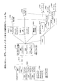
図4に示される第1のHMME制御プレーンモデルにおいては、クライアントデバイス402(たとえば、UE)は、たとえば、接続資格情報、およびホーム認可、認証、および課金(AAA)サーバ407を使用して互いを認証することによって、HMME/SME406とのEMMコンテキスト404(接続コンテキスト)を確立する。単一のEMMコンテキスト404は、クライアントデバイス402とRAN403(たとえば、eNB)との間の単一の無線リンクの確立を容易にする。EMMコンテキスト404が確立されると、クライアントデバイス402は、いくつかのサービス資格情報およびAAAサーバ407、413、415を使用して、いくつかのSME(HMME/SME406、SME412、SME414)との1つまたは複数のESMコンテキスト408(たとえば、ESMコンテキスト1、2、3)を確立し得る。(HMME機能のための)クライアントデバイス402とHMME406との間のNASメッセージは、HMME406に記憶されたデフォルトの接続セキュリティコンテキスト(たとえば、NASセキュリティコンテキスト)に基づいて暗号化され、完全性保護され得る。クライアントデバイス402とSMEとの間のNASメッセージは、SMEにそれぞれ記憶された異なるセキュリティコンテキスト410(NASセキュリティコンテキスト)を使用して暗号化され、完全性保護される。クライアントデバイス402および各SMEは、対応するサービス資格情報を使用して互いを認証する。図4のこの例では、第1のESMコンテキスト(ESMコンテキスト1)は、クライアントデバイス402および第1のSME406に記憶される第1のセキュリティコンテキスト(セキュリティコンテキスト1)を使用して保護される。第2のESMコンテキスト(ESMコンテキスト2)は、クライアントデバイス402および第2のSME412に記憶された第2のセキュリティコンテキスト(セキュリティコンテキスト2)を使用して保護される。第3のESMコンテキスト(ESMコンテキスト3)は、クライアントデバイス402および第3のSME414に記憶される第3のセキュリティコンテキスト(セキュリティコンテキスト3)を使用して保護される。
In the first HMME control plane model shown in Figure 4, client devices 402 (eg, UE) use, for example, connection credentials and home authorization, authentication, and billing (AAA)
HMME/SME406は、第1のサービスネットワーク420に接続された第1のサービス/パケットデータゲートウェイ(S/P GW)418を選択するように構成される。同様に、第2のSME412は、第2のサービスネットワーク424に接続された第2のS/P GW422を選択するように構成される。同様に、第3のSME414は、第3のサービスネットワーク428に接続された第3のS/P GW426を選択するように構成される。第1のサービスネットワーク420、第2のサービスネットワーク424、および第3のサービスネットワーク428は、同じサービスプロバイダまたは異なるサービスプロバイダによって動作され得る。いくつかの例では、サービスゲートウェイ(S-GW)選択は、HMME406によって実行され得る。そのような場合、HMME406は、たとえばサービス要求中に、選択されたS-GWをSMEに通知する。
The HMME / SME406 is configured to select a first service / packet data gateway (S / P GW) 418 connected to the
サービスネットワークは、(たとえば、単一の無線リンク430およびRAN403を含む)接続ネットワーク内に少なくとも部分的に確立された仮想ネットワークであってもよく、1つまたは複数のサービスネットワークは、1つまたは複数のサービスプロバイダ(たとえば、サービスネットワーク1、2、および3)によって提供される特定のまたは異なるサービスに関連付けられる。1つの特定の例では、第1の仮想ネットワークは、無線リンク430、RAN403、第1のHMME/SME406、第1のS/P GW418、および第1のサービスネットワーク420を含む。別の例では、第2の仮想ネットワークは、無線リンク430、RAN403、HMME406、第2のSME412、第2のS/P GW422、および第2のサービスネットワーク424を含む。別の例では、第3の仮想ネットワークは、無線リンク430、RAN403、HMME406、第3のSME414、第3のS/P GW426、および第3のサービスネットワーク428を含む。
The service network may be a virtual network that is at least partially established within the connected network (including, for example, a
図5は、本開示の一態様による、第2のHMME制御プレーンモデルを示す。第1および第2のHMME制御プレーンモデルは同様であるので、重複する説明は簡潔にするために省略され得る。クライアントデバイス402は、HMME406とのEMMコンテキスト404を確立する。EMMコンテキスト404が確立されると、クライアントデバイス402は、いくつかのサービス資格情報およびAAAサーバ407、413、415を使用して、いくつかのSME(HMME/SME406、SME412、SME414)との1つまたは複数のESMコンテキスト408(ESMコンテキスト1、2、3)を確立し得る。クライアントデバイス402および各SME406、412、414は、対応するサービス資格情報を使用して互いに認証し得る。たとえば、クライアントデバイス402は、SMEに対して3つの異なる資格情報を使用し得る。図5の第2のHMME制御プレーンモデルにおいては、HMME406は、サービス接続のためのサービス/パケットデータゲートウェイ(たとえば、S/P GW1、2、3)を直接選択して制御し得る。それは、SMEがサービス/パケットデータゲートウェイを選択する図4の第1のHMME制御プレーンモデルとは異なる。本開示の別の態様では、SME(たとえば、SME412およびSME414)がS/P GWを選択し得、その選択を、選択されたS/P GWを選択するHMME406に転送する。
FIG. 5 shows a second HMME control plane model according to one aspect of the present disclosure. Since the first and second HMME control plane models are similar, duplicate explanations may be omitted for brevity.
図6は、本開示の一態様による、第3のHMME制御プレーンモデルを示す。第1および第3のHMME制御プレーンモデルは同様であるので、重複する説明は簡潔にするために省略され得る。クライアントデバイス402は、HMME406とEMMコンテキスト404を確立する。EMMコンテキスト404が確立されると、クライアントデバイス402は、いくつかのサービス資格情報およびAAAサーバ407、413、415を使用して、いくつかのSME(HMME/SME406、SME412、SME414)との1つまたは複数のESMコンテキスト408(ESMコンテキスト1、2、3)を確立し得る。クライアントデバイス402および各SMEは、サービス資格情報を使用して互いに認証し得る。たとえば、クライアントデバイス402は、サービス接続のための異なるサービス資格情報を有し得る。第3のHMME制御プレーンモデルにおいては、HMME406はESMコンテキスト408(たとえば、ESMコンテキスト1、2、3)に基づいて、サービスゲートウェイ(S-GW)431を選択し得る。次いで、S-GW431は、ESMコンテキスト408に基づいて、パケットデータゲートウェイ(P-GW432、434、436)を選択する。それは、SMEがサービスおよびパケットデータゲートウェイを選択する図4の第1のHMME制御プレーンモデルとは異なる。いくつかの例では、SME(たとえば、SME412およびSME414)は、パケットデータゲートウェイ(たとえば、P-GW1、2、3)を選択し得、その選択を、HMME406を介してS-GW431に転送し得る。次いで、S-GW431は、対応するパケットデータゲートウェイを選択する。図4〜図6のHMME制御プレーンモデルにおいては、異なるサービス接続は、異なるセキュリティコンテキスト410(たとえば、セキュリティコンテキスト1、2、3)によって保護され得る。
FIG. 6 shows a third HMME control plane model according to one aspect of the present disclosure. Since the first and third HMME control plane models are similar, duplicate explanations may be omitted for brevity.
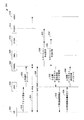
図7〜図8は、本開示の一態様による、単一の接続コンテキストを使用して複数のサービスコンテキストを確立するためのプロセスを示すコールフロー図500である。一例では、本プロセスは、UE(クライアントデバイス)502と、eNB504と、HMME506と、SME508と、サービスゲートウェイ(S-GW)510と、第1のパケットデータゲートウェイ(P-GW)512と、第2のP-GW514と、第1のホーム加入者サーバ(HSS)516と、第2のHSS518とによって実行され得る。コールフロー図500に示されるように、単一の接続コンテキスト(たとえば、EMMコンテキスト)を使用してUE502とネットワーク(たとえば、eNB504)との間に無線リンクまたは無線接続が確立され、次いで、それが複数のサービスコンテキスト(たとえば、SMEコンテキスト)によって共有される。UE502、eNB504、HMME506、SME508、S-GW510、第1のP-GW512、第2のP-GW514、第1のHSS516、および第2のHSS518は、図1〜図6、および図14〜図18のいずれかに示されるものと同じであり得る。
7-8 are call flow diagrams 500 showing the process for establishing multiple service contexts using a single connection context, according to one aspect of the present disclosure. In one example, the process consists of UE (client device) 502, eNB504, HMME506, SME508, service gateway (S-GW) 510, first packet data gateway (P-GW) 512, and second. It can be executed by P-GW514, a first home subscriber server (HSS) 516, and a second HSS518. Call Flow As shown in Figure 500, a wireless link or wireless connection is established between the
UE502は、アタッチ要求520をeNB504に送信することによってネットワークにアタッチしようと試み、eNB504は、初期UEメッセージ522においてHMME506に要求を送信または転送する。初期UEメッセージは、HMME506がクライアントデバイス502を識別し得るようにUE IDを含み得る。UE IDは、上述のデバイス識別子のいずれかであり得る。HMME506は、UE502が要求された接続のための適切な資格情報を有するか否かを決定する。たとえば、HMME506は、UE502が、第1のHSS516と進化型パケットシステム(EPS:Evolved Packet System)認証および鍵合意(AKA)手順524を実行することによって、アタッチすることが許可されているか否かを確認し得る。たとえば、第1のHSS516は、認証ベクトルを生成し、それらをHMME506に送信することによってMMEベース鍵を導出することができ、次いで、HMME506が第1のHSS516の代わりにUE502との認証を実行する。次いで、HMME506は、NASセキュリティモードコマンド(SMC)メッセージ526を交換することによって、UE502とのNASセキュリティ設定手順を実行する。UE502とHMME506との間のNAS SMCメッセージは、たとえば、NAS SMCが完了した場合にHMME506に記憶されたNASセキュリティコンテキスト(確立されている場合)に基づいて暗号化され、完全性保護され得る。次に、HMME506は、S-GW選択機能に基づいてS-GW510を選択し、UE502のためのデフォルトベアラのEPSベアラ識別を割り当てる。次いで、HMME506は、選択されたS-GW510にセッション作成要求528を送信する。それに応答して、S-GW510は、そのEPSベアラテーブル内に新しいエントリを作成し、セッション作成要求メッセージ529を第1のP-GW512に送信する。
UE502 attempts to attach to the network by sending attach
セッション作成要求メッセージ529に応答して、第1のP-GW512は、そのEPSベアラテーブル内に新しいエントリを作成し、課金IDを生成し得る。次いで、第1のP-GW512は、セッション作成応答メッセージ530をS-GW510およびHMME506に送信する。次に、HMME506は、eNB504に、アタッチ受諾メッセージを含む初期コンテキスト設定要求メッセージ532を提供する。次に、eNB504は、EPS無線ベアラ識別およびアタッチ受諾メッセージを含むRRC接続再構成メッセージ534をUE502に送信する。それに応答して、UE502は、RRC接続再構成完了メッセージ536をeNB504に送信する。それに応答して、eNB504は、初期コンテキスト設定応答メッセージ538をHMME506に送信する。
In response to session
上述の手順を利用して、UE502は、EMMコンテキストまたはHMME506との接続を確立することができる。たとえば、この手順は、図4に示される第1のHMME制御プレーンモデルとともに使用され得る。EMMコンテキストが確立された後、UE502は、図8に関して説明した以下の手順を使用して1つまたは複数のSMEコンテキストを確立し得る。
Using the procedure described above, the
図8を参照すると、サービスまたはサービス接続のためのESMコンテキストを確立するために、UE502は、サービス識別子(サービスID)を含むサービス登録メッセージ540をHMME506に送信する。サービス登録メッセージ540を受信すると、HMME506は、UE502によって提供されたサービスIDに基づいてSME(たとえば、SME508)を選択し、初期UEメッセージ542を選択されたSME508に送信する。初期UEメッセージ542は、SME508がUE502を識別し得るように、上述したようなクライアントデバイス識別子(たとえば、SCSI)を含み得る。SME508は、第2のHSS518とのEPS-AKA手順544を実行することによって、UE502がサービスに加入しているか否かを確認し得る。たとえば、第2のHSS518は、認証ベクトルを生成し、それらをSME508に送信することによって鍵を導出することができ、次いで、SME508が第2のHSS518の代わりにUE502との認証を実行する。次いで、SME508は、NASセキュリティモードコマンド(SMC)メッセージ546を交換することによって、UE502とのNASセキュリティ設定手順を実行する。
Referring to FIG. 8, UE502 sends a
UE502とSME508との間のNASメッセージは、ESMセキュリティコンテキストを使用して保護され得る。たとえば、UE502は、SME508と確立されたESMセキュリティコンテキストを使用してNASメッセージを暗号化し、保護し得る。SME508のNASメッセージは、HMME506の外部NASメッセージにカプセル化される(すなわち、NAS-in-NASメッセージカプセル化される)。たとえば、外部NASメッセージは、UE502とHMME506との間に確立されたセキュリティコンテキストを使用して暗号化され、完全性保護される。一例では、図9を参照すると、HMMEのためのカプセル化されたNAS-in-NASメッセージ600は、HMMEが、内部NASメッセージ604が転送されるSME508を識別することを可能にするためにSME ID602を含み得、またSME508がUE502を識別することを可能にするためにUE ID606(SMEによって割り当てられ得る)を含み得る。一例では、UE ID606は、SMEによって割り当てられたGUTIまたはGUTSI(または、他の適切な識別子)を含み得る。
NAS messages between UE502 and SME508 can be protected using the ESM security context. For example, UE502 can encrypt and protect NAS messages using the ESM security context established with SME508. The NAS message of SME508 is encapsulated in the external NAS message of HMME506 (that is, NAS-in-NAS message is encapsulated). For example, external NAS messages are encrypted and integrity protected using the security context established between UE502 and HMME506. As an example, referring to Figure 9, the encapsulated NAS-in-
同様に、SME508は、ESMセキュリティコンテキストを使用してNASメッセージを暗号化し、保護し得る。次いで、NASメッセージ(たとえば、内部NASメッセージ604)は、HMME506のために外部NASメッセージ(または、定義され得る任意の他の適切なコンテナ)にカプセル化される。一例では、外部NASメッセージは保護されないが、安全なチャネルを介してHMME506に転送され得る。一例では、HMME506およびSME508は、安全な通信のためのIPセキュリティ(IPsec)チャネルを確立し得る。外部NASメッセージは、HMME506がUE IDをS1-AP UE IDにマッピングすることを可能にするためにUE IDを含み得る。別の例では、外部NASメッセージは、HMME506のEMMセキュリティコンテキストを使用して暗号化され、完全性保護され得る。 Similarly, the SME508 can use the ESM security context to encrypt and protect NAS messages. The NAS message (eg, internal NAS message 604) is then encapsulated in an external NAS message (or any other suitable container that can be defined) for the HMME506. In one example, external NAS messages are not protected, but can be forwarded to the HMME506 over a secure channel. In one example, the HMME506 and SME508 may establish an IP security (IPsec) channel for secure communication. The external NAS message may include a UE ID to allow the HMME506 to map the UE ID to the S1-AP UE ID. In another example, external NAS messages can be encrypted and integrity protected using the HMME506's EMM security context.
次いで、SME508は、S-GW510にセッション作成要求548を送信する。それに応答して、S-GW510は、そのEPSベアラテーブル内に新しいエントリを作成し、セッション作成要求メッセージを第2のP-GW514に送信する。セッション作成要求メッセージに応答して、第2のP-GW514は、そのEPSベアラテーブル内に新しいエントリを作成し、課金IDを生成し得る。次いで、第2のP-GW514は、セッション作成応答メッセージ550をS-GW510およびSME508に送信する。次に、SME508は、HMME506に、アタッチ受諾メッセージを含む初期コンテキスト設定要求メッセージ552を提供する。HMME506は、初期コンテキスト設定要求メッセージ554をeNB504に転送する。次に、eNB504は、EPS無線ベアラ識別およびアタッチ受諾メッセージを含むRRC接続再構成メッセージ556をUE502に送信する。それに応答して、UE502は、RRC接続再構成完了メッセージ558をeNB504に送信する。次に、eNB504は、初期コンテキスト設定応答メッセージ560をHMME506に送信し、HMME506は、初期コンテキスト設定応答メッセージ562をSME508に転送する。上述の手順により、SME508とのSMEコンテキストが確立される。
The SME508 then sends a
さらに、UE502とeNB504との間にASセキュリティコンテキストを確立するために、ASセキュリティモードコマンド(SMC)メッセージが使用され得る。ASセキュリティコンテキスト(たとえば、図15〜図17に示されるASセキュリティコンテキスト)に基づいて、UE502およびeNB504は、無線トラフィックを保護することができる。単一の無線リンク(たとえば、図1の単一リンク101)が複数のサービス接続のために使用されるが、各サービス接続は、対応するASセキュリティコンテキストに基づいて別個の鍵で保護され、対応する仮想ESM(VESM)タグによって区別され得る。
In addition, AS Security Mode Command (SMC) messages can be used to establish an AS security context between UE502 and eNB504. Based on the AS security context (eg, the AS security context shown in FIGS. 15-17), the
図10〜図11は、本開示の一態様による、単一の接続コンテキストを使用して複数のサービスコンテキストを確立するための手順を示すコールフロー図700である。一例では、本プロセスは、UE702において単一の接続コンテキスト(たとえば、EMMコンテキスト)を使用して無線リンクまたは無線接続を確立するために、UE(クライアントデバイス)702と、eNB704と、HMME706と、SME708と、サービスゲートウェイ(S-GW)710と、第1のパケットデータゲートウェイ(P-GW)712と、第2のパケットデータゲートウェイ(P-GW)714と、第1のホーム加入者サーバ(HSS)716と、第2のHSS718とによって実行され得、次いで、それらの無線リンクまたは無線接続が、複数のサービスコンテキスト(たとえば、SMEコンテキスト)またはサービス接続のために共有される。クライアントデバイス(UE)702、eNB704、HMME706、SME708、S-GW710、第1のP-GW712、第2のP-GW714、第1のHSS716、および第2のHSS718は、図1、図4〜図6、および図14〜図18のいずれかに示されるものと同じであり得る。
10 to 11 are call flow diagrams 700 showing a procedure for establishing a plurality of service contexts using a single connection context according to one aspect of the present disclosure. In one example, the process uses a single connection context (eg, EMM context) in the
流れ図700は、図7および図8の流れ図500と実質的に同様である。したがって、重複する説明は簡潔にするために省略され得る。たとえば、図10に示されるシグナリング手順は、UE702とHMME706との間にEMMコンテキストを確立し、図7に示されたものと実質的に同じである。
The
図11を参照すると、サービスまたはサービス接続のためのESMコンテキストを確立するために、UE702は、サービス識別子(サービスID)を含むサービス登録メッセージ720をHMME706に送信する。サービス登録メッセージ720を受信すると、HMME706は、UE702によって提供されたサービスIDに基づいてSME(たとえば、SME708)を選択し、初期UEメッセージ722を選択されたSME708に送信する。初期UEメッセージ722は、SME708がUE702を識別し得るように、上述したようなクライアントデバイス識別子(たとえば、SCSI)を含み得る。SME708は、第2のHSS718とのEPS-AKA手順724を実行することによって、UE702がサービスに加入しているか否かを確認し得る。たとえば、第2のHSS718は、認証ベクトルを生成し、それらをSME708に送信することによって鍵を導出することができ、次いで、SME708が第2のHSS718の代わりにUE702との認証を実行する。次いで、SME708は、NASセキュリティモードコマンド(SMC)メッセージ726を交換することによって、UE702とのNASセキュリティ設定手順を実行する。
Referring to FIG. 11, UE702 sends a
UE702とSME708との間のNASメッセージは、ESMセキュリティコンテキストを使用して保護され得る。たとえば、UE702は、SME708と確立されたESMセキュリティコンテキストを使用してNASメッセージを暗号化し、保護し得る。たとえば、SME708のNASメッセージは、HMME706の外部NASメッセージにカプセル化される(すなわち、NAS-in-NASメッセージにカプセル化される)。外部NASメッセージは、UE702とHMME706との間に確立されたセキュリティコンテキストを使用して暗号化され、完全性保護される。HMME706のためのカプセル化されたNAS-in-NASメッセージは、HMME706が、内部NASメッセージが転送されるSME708を識別することを可能にするためにSME IDを含み得、またSME708がUE702をしきい別することを可能にするためにUE ID(SMEによって割り当てられ得る)を含み得る。一例では、UE IDは、SMEによって割り当てられたGUTIまたはGUTSI(または、他の適切な識別子)を含み得る。 NAS messages between UE702 and SME708 can be protected using the ESM security context. For example, UE702 can encrypt and protect NAS messages using SME708 and an established ESM security context. For example, SME708 NAS messages are encapsulated in HMME706 external NAS messages (ie, encapsulated in NAS-in-NAS messages). External NAS messages are encrypted and integrity protected using the security context established between UE702 and HMME706. The encapsulated NAS-in-NAS message for the HMME706 may include an SME ID to allow the HMME706 to identify the SME708 to which the internal NAS message is forwarded, and the SME708 will filter the UE702. It may include a UE ID (which can be assigned by the SME) to allow it to be separated. In one example, the UE ID can include a GUTI or GUTSI (or any other suitable identifier) assigned by the SME.
同様に、SME708は、ESMセキュリティコンテキストを使用してNASメッセージを暗号化し、保護し得る。次いで、NASメッセージ(内部NASメッセージ)は、HMME706のために外部NASメッセージ(または、定義され得る任意の他の適切なコンテナ)にカプセル化される。一例では、外部NASメッセージは保護されないが、安全なチャネルを介してHMME706に転送され得る。一例では、HMME706およびSME708は、安全な通信のためのIPセキュリティ(IPsec)チャネルを確立し得る。外部NASメッセージは、HMME706がUE IDをS1-AP UE IDにマッピングすることを可能にするためにUE IDを含み得る。別の例では、外部NASメッセージは、HMME706のEMMセキュリティコンテキストを使用して暗号化され、完全性保護され得る。 Similarly, the SME708 can use the ESM security context to encrypt and protect NAS messages. The NAS message (internal NAS message) is then encapsulated in an external NAS message (or any other suitable container that can be defined) for the HMME706. In one example, external NAS messages are not protected, but can be forwarded to the HMME706 over a secure channel. In one example, the HMME706 and SME708 can establish an IP security (IPsec) channel for secure communication. The external NAS message may include a UE ID to allow the HMME706 to map the UE ID to the S1-AP UE ID. In another example, external NAS messages can be encrypted and integrity protected using the HMME706's EMM security context.
UE702は、以下に説明する手順を使用して、1つまたは複数のSMEコンテキストを確立し得る。たとえば、図11を参照すると、SME708は、HMME706を介してS-GW710にセッション作成要求728を送信する。それに応答して、S-GW710は、そのEPSベアラテーブル内に新しいエントリを作成し、セッション作成要求メッセージ728を第2のP-GW714に送信する。セッション作成要求メッセージに応答して、第2のP-GW714は、そのEPSベアラテーブル内に新しいエントリを作成し、課金IDを生成し得る。次いで、第2のP-GW714は、セッション作成応答メッセージ730をS-GW710に送信し、S-GW710はHMME706を介してメッセージをSME708に転送する。次に、HMME706は、eNB704に、初期コンテキスト設定要求メッセージ732を提供する。次に、eNB704は、EPS無線ベアラ識別およびアタッチ受諾メッセージを含むRRC接続再構成メッセージ734をUE702に送信する。それに応答して、UE702は、RRC接続再構成完了メッセージ736をeNB704に送信する。次に、eNB704は、初期コンテキスト設定応答メッセージ738をHMME706に送信し、HMME706は、初期コンテキスト設定応答メッセージをSME708に転送する。
UE702 may establish one or more SME contexts using the procedure described below. For example, referring to FIG. 11, the SME708 sends a
上述の手順を利用して、UE702は、SME(たとえば、SME708)との1つまたは複数のESMコンテキストまたはサービス接続を確立することができる。たとえば、この手順は、図5に示される第2のHMME制御プレーンモデル、および図6に示される第3のHMME制御プレーンモデルにおいて使用され得る。
Using the steps described above, the
本開示の一態様では、eNBとHMME/SMEとの間の通信は、3GPP仕様において定義されたS1AP(S1アプリケーションプロトコル)を使用し得る。S1APの例は、3GPP TS 36.413-進化型ユニバーサル地上無線アクセスネットワーク(E-UTRAN); S1アプリケーションプロトコル(S1AP)、リリース12において定義されている。S1APメッセージは、NDS/IP(ネットワークドメインセキュリティ/インターネットプロトコル)を使用して保護され得る。NDS/IPは、セキュリティドメインサービスを実装するためにIPセキュリティ(IPSec)を利用する。たとえば、eNBとHMME/SMEとの間のメッセージを保護するためにIPSecトンネルが使用され得る。
In one aspect of the disclosure, communication between the eNB and the HMME / SME may use the S1AP (S1 application protocol) defined in the 3GPP specification. An example of S1AP is defined in 3GPP TS 36.413-Evolved Universal Terrestrial Radio Access Network (E-UTRAN); S1 Application Protocol (S1AP),
本開示の一態様では、eNBとHMMEとの間のメッセージは、LTE標準(たとえば、3GPP TS 36.413)において定義されているようなS1APを使用し得る。図12を参照すると、eNB802とSME804との間のメッセージは、S1APを使用して通信され得、HMME806は、eNBとSMEとの間のプロキシとして実装され得る。eNB802、SME804、およびHMME806は、図4〜図8、図10、図11、および図14〜図18において説明したものと同じであり得る。この例では、HMME806およびSME804は、別々のUE IDを使用し得る。HMME806は、HMME UE IDをSME UE IDに、またはその逆に変換する。eNB802とHMME806との間にIPSecトンネルが作成され、HMME806とSME804との間に別のIPSecトンネルが作成される。IPSecトンネルはNDS/IPによって保護され得る。しかしながら、本開示は、eNBとHMME/SMEとの間の通信のためのS1APに限定されない。本開示のいくつかの態様では、eNBとSMEとの間、HMMEとSMEとの間、eNBとHMMEとの間、またはそれらの組合せの間で、別個の通信プロトコルが使用され得る。
In one aspect of the disclosure, the message between eNB and HMME may use S1AP as defined in the LTE standard (eg, 3GPP TS 36.413). With reference to FIG. 12, the message between the
図13を参照すると、eNB902とSME904との間のS1APは、HMME906を介してトンネリングすることによって実装され得る。eNB902、SME904、およびHMME906は、図4〜図8、図10、図11、および図14〜図18において説明したものと同じであり得る。この例では、登録またはサービス要求中、HMME906は、eNB IDおよびアドレスをSME904に提供する。次いで、eNB902およびSME904は、あらかじめインストールされた資格情報(たとえば、証明書)に基づいて安全なチャネル908を確立し得る。1つの特定の例では、安全なチャネル908は、IPSecトンネル、TLS(トランスポートレイヤセキュリティ)、またはDTLS(データグラムトランスポートレイヤセキュリティ)に基づき得る。この場合、eNB902とSME904との間のS1APメッセージは、透明なコンテナを使用してHMME906を通じてトンネリングする。
With reference to FIG. 13, the S1AP between the
図4〜図6を参照して説明した制御プレーンセキュリティに加えて、クライアントデバイスとSMEとの間の通信を確保するために、追加のセキュリティがユーザプレーンにおいて実装され得る。図14は、本開示の一態様による、拡張されたユーザプレーンセキュリティを有するHMME制御プレーンモデルを示す図である。拡張されたユーザプレーンセキュリティは、図4〜図6に示される3つのすべてのHMME制御プレーンモデルにおいて実装されてもよく、他の適切なHMME制御プレーンモデルにおいて実装されてもよい。たとえば、クライアントデバイス1002(たとえば、UE)は、いくつかのパケットデータゲートウェイ(P-GW)を用いて追加の認証を実行するために、いくつかのユーザプレーン(UP)セキュリティコンテキスト1004を利用し得る。UPセキュリティコンテキスト1004により、サービスプロバイダが、ESMコンテキスト1006およびセキュリティコンテキスト1008によって提供されるものに加えて、クライアントデバイス1002とサービスプロバイダのネットワークとの間のメッセージまたは通信にセキュリティの追加層を提供することが可能になる。さらに、UPセキュリティは、メッセージまたは通信の情報およびコンテンツが接続プロバイダのネットワーク、たとえばRAN1010およびHMMEから遮蔽され得るように、サービスプロバイダによって制御および維持され得る。
In addition to the control plane security described with reference to FIGS. 4-6, additional security may be implemented in the user plane to ensure communication between the client device and the SME. FIG. 14 is a diagram showing an HMME control plane model with enhanced user plane security according to one aspect of the present disclosure. Enhanced user plane security may be implemented in all three HMME control plane models shown in FIGS. 4-6, or in other suitable HMME control plane models. For example, client device 1002 (eg UE) may utilize several user plane (UP)
本開示の一態様では、第1のP-GW1014、第2のP-GW1016、および第3のP-GW1018は、第1のサービスネットワーク1020、第2のサービスネットワーク1022、および第3のサービスネットワーク1024への接続をそれぞれ提供する。第1のP-GW1014は、対応するUPセキュリティコンテキスト(たとえば、UPセキュリティ1)に基づいて第1のHSS/AAA1026との認証手順を実行することによって、クライアントデバイス1002がサービスの有効な加入または資格情報を有するかどうかを確認し得る。第2のP-GW1016は、対応するUPセキュリティコンテキスト(たとえば、UPセキュリティ2)に基づいて、第2のHSS/AAA1028との認証手順を実行することによって、クライアントデバイス1002がサービスの有効な加入または資格情報を有するかどうかを確認し得る。同様に、第3のP-GW1018は、対応するUPセキュリティコンテキスト(たとえば、UPセキュリティ3)に基づいて第3のHSS/AAA1030との認証手順を実行することによって、クライアントデバイス1002がサービスの有効な加入または資格情報を有するかどうかを確認し得る。
In one aspect of the disclosure, the first P-GW1014, the second P-GW1016, and the third P-GW1018 are the
図15〜図17は、本開示のいくつかの態様による、アクセス層セキュリティコンテキストを利用するいくつかの例示的なHMMEユーザプレーンモデルを示す図である。これらの例では、アクセスネットワーク(RAN)との単一のネットワーク接続またはリンクを確立するために、クライアントデバイスごとに1つのEMMコンテキストが使用され、異なるサービスプロバイダ(サービスネットワーク)とのサービス接続を確立するために複数のESMコンテキストおよびアクセス層(AS)セキュリティコンテキストが使用される。EMMコンテキストおよびESMコンテキストは、上記で図7〜図11に関して説明したような手順を使用して確立され得る。ASセキュリティコンテキストは、クライアントデバイスとRANとの間のユーザプレーン通信を安全にし、保護するために使用され得る。これらのHMMEデータプレーンモデルは、上記で図4〜図6において説明したHMME制御プレーンモデル、または他の適切な制御プレーンモデルとともに実装され得る。 15 to 17 are diagrams illustrating some exemplary HMME user plane models that utilize access layer security contexts, according to some aspects of the present disclosure. In these examples, one EMM context is used for each client device to establish a single network connection or link with an access network (RAN), establishing a service connection with a different service provider (service network). Multiple ESM contexts and access layer (AS) security contexts are used to do this. EMM and ESM contexts can be established using procedures as described above for FIGS. 7-11. The AS security context can be used to secure and secure user plane communication between the client device and the RAN. These HMME data plane models can be implemented with the HMME control plane model described above in FIGS. 4-6, or any other suitable control plane model.
図15は、図4および図5に示されるHMME制御プレーンモデル、または他の適切なHMME制御プレーンモデルを用いて実装され得る第1のHMMEデータプレーンモデル1100を示す。図15に示される例では、クライアントデバイス1102とRAN1104との間のUE-to-RANデータプレーントラフィックについて、クライアントデバイス1102(たとえば、UE)は、ESMコンテキスト1108から特定のサービスネットワーク宛のメッセージに対応するASセキュリティコンテキスト1106を決定する。この例では、3つのESMコンテキスト1108から3つのASセキュリティコンテキスト1106が導出される。クライアントデバイス1102は、第1のサービスネットワーク1110との第1のESMコンテキスト(ESMコンテキスト1)と、第2のサービスネットワーク1112との第2のESMコンテキスト(ESMコンテキスト2)と、第3のサービスネットワーク1114との第3のESMコンテキスト(ESMコンテキスト3)とを確立している。第1のHMMEデータプレーンモデル1100は、異なるP-GW1118のために別々のS-GW1116を使用する。
FIG. 15 shows a first HMME
制御メッセージ(たとえば、RRCメッセージ)の場合、クライアントデバイス1102は、ASセキュリティコンテキストに基づいて、メッセージを暗号化および完全性保護し、メッセージにVESMタグを追加し得る。データメッセージの場合、クライアントデバイス1102は、ASセキュリティコンテキストに基づいて、データメッセージを暗号化し、VESMタグをメッセージに追加し得る。
For control messages (for example, RRC messages),
RAN-to-UEデータプレーントラフィックの場合、RANノード1104(たとえば、eNB)は、UEまたはクライアントデバイス1102に送信されるメッセージのASセキュリティコンテキストを決定する。一例では、制御メッセージ(たとえば、RRCメッセージ)の場合、HMME(図15には図示せず)のESMセキュリティコンテキストから導出されたデフォルトのASセキュリティコンテキストが使用され得る。RAN1104(たとえば、eNB)において、セッションコンテキスト1120(たとえば、セッションコンテキスト1、2、3)は、クライアント1102(たとえば、UE)からS-GW1116に、またはその逆に、パケットを転送するために使用される情報を提供する。たとえば、セッションコンテキストは、ベアラID、QoS情報、トンネルエンドポイントIDなどを含み得る。S-GW1116におけるセッションコンテキストは、RAN1104のセッションコンテキストと同様である。たとえば、これらのコンテキストは、P-GW1118から受信されたクライアント1102のパケットをRAN1104(たとえばeNB)に、およびその逆に転送するために使用される情報を提供し得る。
For RAN-to-UE data plane traffic, the RAN node 1104 (for example, eNB) determines the AS security context for messages sent to the UE or
制御メッセージ(たとえば、RRCメッセージ)の場合、RANノード1104は、ASセキュリティコンテキストに基づいて、メッセージを暗号化および完全性保護し、メッセージにVESMタグを追加し得る。データメッセージの場合、RANノード1104は、ASセキュリティコンテキストに基づいて、メッセージを暗号化し、メッセージにVESMタグを追加し得る。一例では、VESMタグは、TEID(一意のトンネルエンドポイント識別子)およびS-GW IPアドレスから決定され得る。RANノード1104からメッセージを受信すると、クライアントデバイス1102は、VESMタグに基づいてメッセージを検証するために、対応するASセキュリティコンテキストを決定し得る。
For control messages (eg RRC messages),
図16は、図6に示されるHMME制御プレーンモデル、または他の適切なHMME制御プレーンモデルを用いて実装され得る第2のHMMEデータプレーンモデル1200を示す。第2のHMMEデータプレーンモデル1200において、クライアントデバイス1202とRAN1204との間のUE-to-RANデータプレーントラフィックについて、クライアントデバイス1202(たとえば、UE)は、特定のサービスネットワーク宛のメッセージに対応するASセキュリティコンテキスト1206を決定する。この例では、ESMコンテキスト1208から3つのASセキュリティコンテキスト1206が導出される。クライアントデバイス1202は、第1のサービスネットワーク1210との第1のESMコンテキスト(ESMコンテキスト1)と、第2のサービスネットワーク1212との第2のESMコンテキスト(ESMコンテキスト2)と、第3のサービスネットワーク1214との第3のESMコンテキスト(ESMコンテキスト3)とを確立している。第2のHMMEデータプレーンモデル1200は、異なるP-GW1218のために共通のS-GW1216を使用する。第2のHMMEデータプレーンモデル1200は、第1のHMMEデータプレーンモデル1100と同様であり、簡潔にするために、第2のHMMEデータプレーンモデル1200の重複した説明は繰り返さない。
FIG. 16 shows a second HMME
図17は、図6に示されるHMME制御プレーンモデル、または他の適切なHMME制御プレーンモデルを用いて実装され得る第3のHMMEデータプレーンモデル1300を示す。クライアントデバイス1302は、第1のサービスネットワーク1310、第2のサービスネットワーク1312、および第3のサービスネットワーク1314のために、それぞれ異なるESMコンテキスト1308、たとえば第1のESMコンテキスト、第2のESMコンテキスト、および第3のESMコンテキストを確立していていよい。この特定の例では、UE-to-RANデータプレーントラフィックについて、クライアントデバイス1302(たとえば、UE)は、EMMセキュリティコンテキスト1309から導出されたデフォルトのASセキュリティコンテキスト1306を使用し得る。別の例では、ESMセキュリティコンテキスト1308から導出されたASセキュリティコンテキストが、デフォルトのASセキュリティコンテキストとして設定され得る。制御メッセージ(たとえば、RRCメッセージ)の場合、クライアントデバイス1302は、ASセキュリティコンテキストに基づいて、メッセージを暗号化および完全性保護し、VESMタグを制御メッセージに追加し得る。データメッセージの場合、クライアントデバイス1302は、ASセキュリティコンテキストに基づいて、データメッセージを暗号化し、VESMタグをメッセージに追加し得る。
FIG. 17 shows a third HMME
RAN1304において、セッションコンテキスト1320(たとえば、セッションコンテキスト1、2、3)は、クライアント1302(たとえば、UE)からS-GW1316に、またはその逆にパケットを転送するために使用される情報を提供する。たとえば、セッションコンテキストは、ベアラID、QoS情報、トンネルエンドポイントIDなどを含み得る。S-GW1316におけるセッションコンテキストは、RAN1304のセッションコンテキストと同様である。たとえば、これらのコンテキストは、P-GW1318から受信されたクライアント1302のパケットをRAN1304(たとえばeNB)に、およびその逆に転送する方法に関する情報を含み得る。
In RAN1304, session context 1320 (eg,
上述のデータプレーンモデルでは、RANにおいて、UEコンテキストは、たとえばセッションコンテキスト、ASセキュリティコンテキスト、およびクライアントに関連する他の状態を含む、クライアント(たとえば、UE)に関する情報を含む。同様に、HMMEにおいて、UEコンテキストは、EMM/ESMコンテキスト、セキュリティコンテキスト、および、たとえばIMSI、TMSIなどの他の状態を含むクライアントに関する情報を含む。 In the data plane model described above, in the RAN, the UE context contains information about the client (eg, UE), including, for example, the session context, the AS security context, and other states associated with the client. Similarly, in HMME, the UE context contains information about the client, including the EMM / ESM context, the security context, and other states such as the IMSI, TMSI.
RAN-to-UEデータプレーントラフィックの場合、RANノード1304(たとえば、eNB)は、HMME(図17には図示せず)によってプロビジョニングされたデフォルトのASセキュリティコンテキストを使用し得る。制御メッセージ(たとえば、RRCメッセージ)の場合、RANノード1304(たとえば、eNB)は、ASセキュリティコンテキストに基づいて、メッセージを暗号化および完全性保護し、メッセージにVESMタグを追加し得る。データメッセージの場合、RANノード1304は、ASセキュリティコンテキストに基づいて、メッセージを暗号化し、メッセージにVESMタグを追加し得る。たとえば、VESMタグは、TEIDおよびS-GWのIPアドレスから決定され得る。
For RAN-to-UE data plane traffic, RAN node 1304 (eg, eNB) may use the default AS security context provisioned by HMME (not shown in Figure 17). For control messages (eg RRC messages), RAN node 1304 (eg eNB) can encrypt and integrity the message and add VESM tags to the message based on the AS security context. For data messages,
図18は、本開示の態様による、例示的なユーザプレーンセキュリティ終了モデル1400の例を示す図である。図15〜図17において説明したのと同様のクライアントデバイス1402は、RAN1404と確立された単一のESMコンテキストを有する。RAN1404は、異なるパケットデータゲートウェイ(P-GW)1408にそれぞれ接続された3つのS-GW1406に接続されている。P-GW1408の各々は、対応するサービスネットワーク1410へのアクセスを提供する。EMMコンテキストおよび複数のESMコンテキストは、図7〜図11に関して上述した手順を使用して確立され得る。この例では、ユーザプレーンセキュリティ(UPセキュリティ)は、パケットデータゲートウェイ1408(P-GW1、P-GW2、P-GW3)において終了する。このユーザプレーンセキュリティ終了モデルは、図15〜図17に示されるデータプレーンモデルにおいて使用され得る。UPセキュリティは、サービスプロバイダがアクセスネットワーク(たとえば、RAN1404)からユーザデータトラフィックを保護することを可能にする。本開示の様々な態様では、ASセキュリティコンテキストは、クライアントデバイスとRANとの間のデータ無線ベアラ(DRB)とシグナリング無線ベアラ(SRB)との両方を保護するために使用され得、UPセキュリティはDRB保護とは別に適用される。
FIG. 18 is a diagram illustrating an example of an exemplary user plane
図19は、本開示の一態様による、複数の同時または並行サービスコンテキストを確立するためにクライアントデバイスにおいて動作可能な例示的な方法1500を示すフローチャートである。方法1500は、図1、図2、図4〜図8、図10、図11、および/または図14〜図18のいずれかに示されるクライアントデバイスにおいて実行され得る。ブロック1502において、クライアントデバイスは、第1の資格情報に基づいて、接続ネットワークとのワイヤレスリンクまたは接続を確立する。ブロック1504において、クライアントデバイスは、接続に対応する接続コンテキストを確立する。たとえば、クライアントデバイス(UE)は、接続資格情報を使用してアクセスネットワーク(たとえば、RAN)にアタッチし、HMME(たとえば、図4〜図6のHMME)を利用してRANへの単一の接続を確立し得る。いくつかの例では、HMMEは、コアネットワーク内に存在し得る。この時点で、単一のEMMコンテキストまたは接続が確立される。一例では、クライアントデバイスは、ワイヤレスリンクおよび接続コンテキストを確立するために、無線リンク確立モジュール210およびワイヤレスネットワーク通信インターフェース204(図2参照)を利用し得る。
FIG. 19 is a flow chart illustrating an
ブロック1506において、クライアントデバイスは、接続ネットワークに関連付けられる1つまたは複数のサービスネットワークを識別する。たとえば、クライアントデバイスは、1つまたは複数のサービスネットワーク宛の第1のメッセージを送信し得、第1のメッセージは、アクセスネットワークのネットワークノード(たとえば、HMME)宛の第2のメッセージにカプセル化される。メッセージが、宛先のネットワークの特定のエンティティ(たとえば、サービスネットワークのHMMEまたはSME)宛であるとき、そのメッセージは特定のネットワーク宛である。たとえば、サービスネットワークは、図4〜図6、および図14〜図17に示されるサービスネットワークであり得る。クライアントデバイスは、サービスネットワークを識別するために、図7、図8、図10、および図11に示されるものと同様の手順を実行するために、サービスコンテキスト確立モジュール212(図2参照)を利用し得る。
In
ブロック1508において、クライアントデバイスは、確立されたワイヤレスリンクまたは接続を利用するサービスネットワークとの1つまたは複数のサービス接続を確立し、1つまたは複数のサービス接続は、それぞれの第2の資格情報を使用して確立される。ブロック1510において、クライアントデバイスは、サービス接続にそれぞれ対応する1つまたは複数のサービスコンテキストを確立する。サービスコンテキストは、異なるセキュリティコンテキストを含み得る。セキュリティコンテキストの各々はNASセキュリティコンテキストとASセキュリティコンテキストを含み、NASセキュリティコンテキストとASセキュリティコンテキストの両方が同じ第2の資格情報に対応する。たとえば、サービスコンテキストは図4〜図6および図14〜図17において説明したESMコンテキストであってもよく、セキュリティコンテキストは図4〜図6および図14〜図17において説明したセキュリティコンテキストであってもよい。クライアントデバイスは、サービス接続およびコンテキストを確立するために、図7、図8、図10、および図11に示されたものと同様の手順を実行するために、サービスコンテキスト確立モジュール212を利用し得る。サービス接続の各々は、対応するASセキュリティコンテキストに基づいて別個の鍵で保護され、対応するVESMタグによって区別され得る。
In block 1508, the client device establishes one or more service connections with a service network that utilizes an established wireless link or connection, and one or more service connections each have a second credential. Established using. At
図20は、本開示の一態様による方法1500の追加の手順を示すフローチャートである。ブロック1512において、クライアントデバイスは、1つまたは複数のサービスネットワークにそれぞれ関連付けられる複数のパケットデータゲートウェイ(P-GW)から受信した、またはそこに送信されるパケットを保護するために、複数のユーザプレーン(UP)セキュリティコンテキストを利用し得る。たとえば、P-GWは、図4〜図8、図10、図11、および図14〜図18のいずれかに示されるP-GWであり得る。
FIG. 20 is a flowchart showing an additional procedure of
図21は、本開示の一態様による、接続ネットワークのネットワークノードにおいて動作可能な例示的な方法1600を示すフローチャートである。方法1600は、図1、図3、図4〜図8、および図10〜図18のいずれかに示されるネットワークノード(たとえば、HMME)において実行され得る。ブロック1602において、接続ネットワークのネットワークノードは、接続資格情報に基づいてクライアントデバイスとのワイヤレスリンクまたは第1の接続を確立する。ブロック1604において、ネットワークノードは、第1の接続に対応する接続コンテキストを確立する。たとえば、ネットワークノードは、接続資格情報を使用してクライアントデバイスとの単一の接続および対応するEMMテキストを確立するためにクライアントデバイス(UE)から第1のアタッチ要求を受信するHMME(たとえば、図4〜図14に示されるHMME)であってもよい。ネットワークノードは、図7〜図11において説明した手順を使用してクライアントデバイス(図3参照)と単一のリンクおよびEMMコンテキストを確立するために、無線リンク確立モジュール310と、ネットワーク通信インターフェース304と、HMMEモジュール312とを利用し得る。
FIG. 21 is a flow chart illustrating an
クライアントデバイスとの単一のワイヤレスリンクが確立された後、ブロック1606において、ネットワークノードは、クライアントデバイスから、接続ネットワークに関連付けられる1つまたは複数のサービスネットワークとの接続を確立する要求を受信し得る。たとえば、サービスネットワークは、図4〜図6および図14〜図18に示されるサービスネットワークまたはプロバイダであり得る。要求は、既存のワイヤレスリンクまたは接続を使用して、サービスネットワークまたはプロバイダのうちの1つまたは複数と別個のESMコンテキストを確立するための第2のアタッチ要求を含み得る。ESMコンテキストの各々は、異なるセキュリティコンテキストに対応し得る。ネットワークノードは、クライアントデバイスから要求を受信するために、ネットワーク通信インターフェース304(図3参照)を利用し得る。
After a single wireless link with the client device is established, at
ブロック1608において、ネットワークノードは、ネットワークノードをプロキシとして利用して、クライアントデバイス用のサービスネットワークとの1つまたは複数の第2の接続をそれぞれ確立する。一例では、ネットワークノードは、図7〜図11において説明した手順を使用して、第2の接続および対応するコンテキストを確立するために、SMEモジュール314を利用し得る。
In
図22は、本開示の一態様による、方法1600の追加の手順を示すフローチャートである。ブロック1610において、ネットワークノードはクライアントデバイスからメッセージを受信し得、メッセージは、サービスネットワーク宛の別のメッセージをカプセル化する。たとえば、メッセージは、図8および図11に示されるNASカプセル化メッセージであり得る。
FIG. 22 is a flowchart showing an additional procedure of
図23は、本開示の一態様による、サービスネットワークのネットワークノードにおいて動作可能な例示的な方法1700を示すフローチャートである。方法1700は、図1、図3、図4〜図8、および図10〜図18のいずれかに示されるネットワークノード(たとえば、SME)において実行され得る。ブロック1702において、ネットワークノードは、クライアントデバイスから接続を確立する要求を受信する。たとえば、SMEは、要求を受信するために、そのネットワーク通信インターフェース304(図3参照)を利用し得る。ブロック1704において、ネットワークノードは、接続ネットワークのネットワークノード(たとえば、HMME)を介してクライアントデバイスとの接続を確立する。この例では、ネットワークノードは、接続を確立するためにサービス管理エンティティモジュール/回路/機能314を利用し得る。ブロック1706において、ネットワークノードは、接続に対応するサービスコンテキストを確立し、サービスコンテキストはセキュリティコンテキストに関連付けられる。たとえば、サービス管理エンティティモジュール/回路/機能314は、サービスコンテキスト334(図3参照)を確立するためにSME命令318によって構成され得る。
FIG. 23 is a flowchart illustrating an
開示されたプロセスにおけるステップの特定の順序または階層は、例示的な手法の実例であることが理解される。設計選好に基づいて、プロセスにおけるステップの特定の順序または階層が並べ替えられてよいことが理解される。添付の方法クレームは、サンプル順序における様々なステップの要素を提示し、提示される特定の順序または階層に限定されることを意味しない。 It is understood that the particular order or hierarchy of steps in the disclosed process is an example of an exemplary approach. It is understood that the particular order or hierarchy of steps in the process may be reordered based on design preferences. The attached method claims present the elements of the various steps in the sample order and are not meant to be limited to the particular order or hierarchy presented.
101 無線リンク
102 クライアントデバイス
104 サービスプロバイダ
104 プロビジョニング機能
106 プロビジョニング機能
106 サービスプロバイダ
108 サービスコンテキスト
108 第1のサービスコンテキスト
110 サービスコンテキスト
110 第2のサービスコンテキスト
112 サービスコンテキスト
112 第3のサービスコンテキスト
114 サービス接続
116 サービス接続
118 サービス接続
120 無線アクセスネットワーク(RAN)
122 接続コンテキスト
124 ネットワークホストモビリティ管理エンティティ(HMME)
126 EMM/ESMコンテキスト
128 サービス管理エンティティ(SME)
130 サービス管理エンティティ
132 サービスゲートウェイ(S-GW)
132 パケットデータネットワークゲートウェイ
134 サービスゲートウェイ
134 パケットデータネットワークゲートウェイ
136 ESMコンテキスト
138 ESMコンテキスト
140 AAAサーバ
142 AAAサーバ
144 ホーム認可、認証、および課金(H-AAA)サーバ
202 クライアントデバイス
204 ワイヤレスネットワーク通信インターフェース
206 プロセッサ
208 メモリ/ストレージ
208 メモリ/ストレージデバイス
210 無線リンク確立モジュール/回路/機能
212 サービスコンテキスト確立モジュール/回路/機能
213 ユーザプレーン(UP)セキュリティコンテキスト確立モジュール/回路/機能
216 無線リンク確立命令
218 サービスコンテキスト確立命令
219 セキュリティコンテキスト確立命令
226 受信機モジュール/回路/機能
228 送信機モジュール/回路/機能
230 アンテナモジュール/回路/機能
232 接続コンテキスト
234 サービスコンテキスト
235 セキュリティコンテキスト
302 ネットワークノード
304 ネットワーク通信インターフェース
306 プロセッサ
308 メモリ/ストレージ
310 無線リンク確立モジュール/回路/機能
312 HMMEモジュール/回路/機能
314 サービス管理エンティティ(SME)モジュール/回路/機能
316 無線リンク確立命令
318 HMME/SME命令
326 受信機モジュール/回路/機能
328 送信機モジュール/回路/機能
330 アンテナモジュール/回路/機能
332 接続コンテキスト
334 サービスコンテキスト
335 セキュリティコンテキスト
402 クライアントデバイス
404 EMMコンテキスト
403 RAN
406 HMME/SME
406 第1のSME
406 第1のHMME/SME
407 ホーム認可、認証、および課金(AAA)サーバ
408 ESMコンテキスト
410 セキュリティコンテキスト
412 第2のSME
413 AAAサーバ
414 第3のSME
415 AAAサーバ
420 第1のサービスネットワーク
418 第1のサービス/パケットデータゲートウェイ(S/P GW)
420 第1のサービスネットワーク
422 第2のS/P GW
424 第2のサービスネットワーク
426 第3のS/P GW
428 第3のサービスネットワーク
430 無線リンク
431 サービスゲートウェイ(S-GW)
432 パケットデータゲートウェイ(P-GW)
434 パケットデータゲートウェイ
436 パケットデータゲートウェイ
500 コールフロー図
502 UE(クライアントデバイス)
504 eNB
506 HMME
508 SME
510 サービスゲートウェイ(S-GW)
512 第1のパケットデータゲートウェイ(P-GW)
514 第2のP-GW
516 第1のホーム加入者サーバ(HSS)
518 第2のHSS
520 アタッチ要求
522 初期UEメッセージ
524 認証および鍵合意(AKA)手順
526 NASセキュリティモードコマンド(SMC)メッセージ
528 セッション作成要求
529 セッション作成要求メッセージ
530 セッション作成応答メッセージ
532 初期コンテキスト設定要求メッセージ
534 RRC接続再構成メッセージ
536 RRC接続再構成完了メッセージ
538 初期コンテキスト設定応答メッセージ
540 サービス登録メッセージ
542 初期UEメッセージ
546 NASセキュリティモードコマンド(SMC)メッセージ
548 セッション作成要求
550 セッション作成応答メッセージ
552 初期コンテキスト設定要求メッセージ
554 初期コンテキスト設定要求メッセージ
556 RRC接続再構成メッセージ
558 RRC接続再構成完了メッセージ
560 初期コンテキスト設定応答メッセージ
562 初期コンテキスト設定応答メッセージ
600 NAS-in-NASメッセージ
602 SME ID
604 内部NASメッセージ
700 コールフロー図
702 クライアントデバイス
702 UE(クライアントデバイス)
704 eNB
706 HMME
708 SME
710 サービスゲートウェイ(S-GW)
712 第1のパケットデータゲートウェイ(P-GW)
714 第2のパケットデータゲートウェイ(P-GW)
716 第1のホーム加入者サーバ(HSS)
718 第2のHSS
720 サービス登録メッセージ
722 初期UEメッセージ
724 EPS-AKA手順
726 NASセキュリティモードコマンド(SMC)メッセージ
728 セッション作成要求メッセージ
730 セッション作成応答メッセージ
732 初期コンテキスト設定要求メッセージ
734 RRC接続再構成メッセージ
736 RRC接続再構成完了メッセージ
738 初期コンテキスト設定応答メッセージ
802 eNB
804 SME
806 HMME
902 eNB
904 SME
906 HMME
908 安全なチャネル
1002 クライアントデバイス
1004 ユーザプレーン(UP)セキュリティコンテキスト
1006 ESMコンテキスト
1008 セキュリティコンテキスト
1010 RAN
1014 第1のP-GW
1016 第2のP-GW
1018 第3のP-GW
1020 第1のサービスネットワーク
1022 第2のサービスネットワーク
1024 第3のサービスネットワーク
1026 第1のHSS/AAA
1028 第2のHSS/AAA
1030 第3のHSS/AAA
1100 第1のHMMEデータプレーンモデル
1102 クライアントデバイス
1104 RAN
1104 RANノード
1106 ASセキュリティコンテキスト
1108 ESセキュリティコンテキスト
1110 第1のサービスネットワーク
1112 第2のサービスネットワーク
1114 第3のサービスネットワーク
1116 S-GW
1118 P-GW
1120 セッションコンテキスト
1200 第2のHMMEデータプレーンモデル
1202 クライアントデバイス
1204 RAN
1206 ASセキュリティコンテキスト
1208 ESMコンテキスト
1210 第1のサービスネットワーク
1212 第2のサービスネットワーク
1214 第3のサービスネットワーク
1216 S-GW
1218 P-GW
1300 第3のHMMEデータプレーンモデル
1302 クライアントデバイス
1302 クライアント
1304 RANノード
1304 RAN
1306 ASセキュリティコンテキスト
1308 ESMコンテキスト
1308 ESMセキュリティコンテキスト
1309 EMMセキュリティコンテキスト
1310 第1のサービスネットワーク
1312 第2のサービスネットワーク
1314 第3のサービスネットワーク
1316 S-GW
1318 P-GW
1320 セッションコンテキスト
1400 ユーザプレーンセキュリティ終了モデル
1402 クライアントデバイス
1404 RAN
1406 S-GW
1408 パケットデータゲートウェイ(P-GW)
1410 サービスネットワーク
1500 方法
1600 方法
1700 方法
101 wireless link
102 Client device
104 Service Provider
104 Provisioning function
106 Provisioning function
106 Service Provider
108 Service context
108 First service context
110 Service context
110 Second service context
112 Service context
112 Third service context
114 Service connection
116 Service connection
118 Service connection
120 Radio Access Network (RAN)
122 Connection context
124 Network Host Mobility Management Entity (HMME)
126 EMM / ESM context
128 Service Management Entity (SME)
130 Service Management Entity
132 Service Gateway (S-GW)
132 Packet Data Network Gateway
134 Service Gateway
134 Packet Data Network Gateway
136 ESM context
138 ESM context
140 AAA server
142 AAA server
144 Home Authorization, Authentication, and Billing (H-AAA) Server
202 Client device
204 Wireless network communication interface
206 processor
208 memory / storage
208 memory / storage device
210 Wireless link establishment module / circuit / function
212 Service context establishment module / circuit / function
213 User Plane (UP) Security Context Establishment Module / Circuit / Function
216 Wireless link establishment command
218 Service context establishment instruction
219 Security context establishment instruction
226 Receiver module / circuit / function
228 Transmitter module / circuit / function
230 Antenna Module / Circuit / Function
232 Connection context
234 Service context
235 Security context
302 network node
304 Network communication interface
306 processor
308 Memory / Storage
310 Wireless link establishment module / circuit / function
312 HMME Module / Circuit / Function
314 Service Management Entity (SME) Modules / Circuits / Features
316 Wireless link establishment command
318 HMME / SME instruction
326 Receiver module / circuit / function
328 Transmitter module / circuit / function
330 Antenna Module / Circuit / Function
332 Connection context
334 Service context
335 Security context
402 Client device
404 EMM context
403 RAN
406 HMME / SME
406 First SME
406 1st HMME / SME
407 Home Authorization, Authentication, and Billing (AAA) Server
408 ESM context
410 security context
412 Second SME
413 AAA server
414 Third SME
415 AAA server
420 First service network
418 First Service / Packet Data Gateway (S / P GW)
420 First service network
422 Second S / P GW
424 Second service network
426 Third S / P GW
428 Third service network
430 wireless link
431 Service Gateway (S-GW)
432 Packet Data Gateway (P-GW)
434 Packet data gateway
436 Packet data gateway
500 call flow diagram
502 UE (client device)
504 eNB
506 HMME
508 SME
510 Service Gateway (S-GW)
512 First Packet Data Gateway (P-GW)
514 Second P-GW
516 First Home Subscriber Server (HSS)
518 Second HSS
520 Attach request
522 Initial UE message
524 Authentication and Key Agreement (AKA) Procedure
526 NAS Security Mode Command (SMC) message
528 Session creation request
529 Session creation request message
530 Session creation response message
532 Initial context setting request message
534 RRC connection reconfiguration message
536 RRC connection reconfiguration complete message
538 Initial context setting response message
540 Service registration message
542 Initial UE message
546 NAS Security Mode Command (SMC) message
548 Session creation request
550 Session creation response message
552 Initial context setting request message
554 Initial context setting request message
556 RRC connection reconfiguration message
558 RRC connection reconfiguration complete message
560 Initial context setup response message
562 Initial context setup response message
600 NAS-in-NAS message
602 SME ID
604 Internal NAS message
700 call flow diagram
702 client device
702 UE (client device)
704 eNB
706 HMME
708 SME
710 Service Gateway (S-GW)
712 First Packet Data Gateway (P-GW)
714 Second Packet Data Gateway (P-GW)
716 First Home Subscriber Server (HSS)
718 Second HSS
720 Service registration message
722 Initial UE message
724 EPS-AKA procedure
726 NAS Security Mode Command (SMC) message
728 Session creation request message
730 Session creation response message
732 Initial context setting request message
734 RRC connection reconfiguration message
736 RRC connection reconfiguration complete message
738 Initial context setup response message
802 eNB
804 SME
806 HMME
902 eNB
904 SME
906 HMME
908 Safe Channel
1002 client device
1004 User Plane (UP) Security Context
1006 ESM context
1008 Security context
1010 RAN
1014 1st P-GW
1016 Second P-GW
1018 Third P-GW
1020 First service network
1022 Second service network
1024 Third service network
1026 1st HSS / AAA
1028 Second HSS / AAA
1030 Third HSS / AAA
1100 1st HMME data plane model
1102 client device
1104 RAN
1104 RAN node
1106 AS security context
1108 ES security context
1110 First service network
1112 Second service network
1114 Third service network
1116 S-GW
1118 P-GW
1120 session context
1200 Second HMME data plane model
1202 client device
1204 RAN
1206 AS security context
1208 ESM context
1210 First service network
1212 Second service network
1214 Third service network
1216 S-GW
1218 P-GW
1300 Third HMME data plane model
1302 client device
1302 client
1304 RAN node
1304 RAN
1306 AS security context
1308 ESM context
1308 ESM security context
1309 EMM security context
1310 First service network
1312 Second service network
1314 Third service network
1316 S-GW
1318 P-GW
1320 session context
1400 User Plane Security Termination Model
1402 client device
1404 RAN
1406 S-GW
1408 Packet Data Gateway (P-GW)
1410 Service network
1500 method
1600 method
1700 method
Claims (16)
第1の資格情報に基づいて接続ネットワークとの接続コンテキストを使用してホストモビリティ管理エンティティ(HMME)との接続を確立するステップと、
前記接続ネットワークとの確立された接続コンテキストを利用して、前記接続ネットワークに関連付けられる1つまたは複数のサービスネットワークとの1つまたは複数のサービスコンテキストを使用してサービス管理エンティティ(SME)との1つまたは複数のサービス接続を確立するステップであって、前記1つまたは複数のサービスコンテキストが、1つまたは複数の第2の資格情報を使用して確立される、ステップとを備え、
前記1つまたは複数のサービスコンテキストが、それぞれ異なるセキュリティコンテキストを備え、
前記セキュリティコンテキストの各々が、両方とも同じ第2の資格情報に対応する、非アクセス層(NAS)セキュリティコンテキストおよびアクセス層(AS)セキュリティコンテキストを備える、
方法。 A method of operating a client device in a wireless communication network.
Steps to establish a connection with the Host Mobility Management Entity (HMME) using the connection context with the connection network based on the first credential, and
One with a service management entity (SME) using one or more service contexts with one or more service networks associated with said connection network, taking advantage of the established connection context with said connection network. A step of establishing one or more service connections , wherein the one or more service contexts are established using one or more second credentials.
The one or more service contexts have different security contexts.
Each of the security contexts has a non-access layer (NAS) security context and an access layer (AS) security context, both of which correspond to the same second credential.
Method.
ASセキュリティコンテキストが、1つまたは複数のシグナリング無線ベアラ、1つまたは複数のデータ無線ベアラ、あるいはシグナリング無線ベアラとデータ無線ベアラとの組合せのうちの少なくとも1つを保護するように構成される、
請求項1に記載の方法。 NAS security context, and the client device is configured to protect the HMME or control messages between at least one of bracts of said SME,
The AS security context is configured to protect at least one of one or more signaling radio bearers, one or more data radio bearers, or a combination of signaling radio bearers and data radio bearers.
The method according to claim 1.
前記1つまたは複数のサービスネットワーク宛のメッセージを送信するステップを備え、
前記メッセージが、前記接続ネットワークの前記HMME宛のメッセージにカプセル化される、
請求項1に記載の方法。 The step of establishing one or more service contexts
With the step of sending a message destined for one or more of the service networks mentioned above,
The message is encapsulated in a message addressed to the HMME of the connection network,
The method according to claim 1.
前記1つまたは複数のサービスネットワークが、それぞれ異なるサービスに関連付けられる、
請求項1に記載の方法。 The one or more service networks include at least a partially established virtual network within the connected network.
The one or more service networks are associated with different services.
The method according to claim 1.
請求項1に記載の方法。 Each of the service contexts is protected by a separate key based on the corresponding AS security context and is distinguished by the corresponding Virtual Evolved Packet System (EPS) session management tag.
The method according to claim 1.
前記パケットを保護するステップが、
前記パケットを暗号化するステップ、
前記パケットを完全性保護するステップ、または
前記パケットを暗号化および完全性保護するステップのうちの少なくとも1つを備える、
請求項1に記載の方法。 Further steps to utilize multiple user plane (UP) security contexts to protect packets received or sent from multiple packet data gateways, each associated with the one or more service networks. Prepare,
The step of protecting the packet is
Steps to encrypt the packet,
It comprises at least one of a step of integrity-protecting the packet or a step of encrypting and integrity-protecting the packet.
The method according to claim 1.
接続資格情報に基づいてクライアントデバイスとの第1の接続コンテキストを使用してホストモビリティ管理エンティティ(HMME)との接続を確立するステップであって、前記ネットワークノードが前記HMMEを備える、ステップと、
前記クライアントデバイスから、サービス管理エンティティ(SME)との1つまたは複数のサービス接続を確立する要求を受信するステップと、
前記ネットワークノードをプロキシとして利用して、1つまたは複数のサービス資格情報を使用して前記クライアントデバイス用の1つまたは複数のサービスネットワークとの1つまたは複数のサービスコンテキストを使用した前記1つまたは複数のサービス接続をそれぞれ確立するステップとを備え、
前記1つまたは複数のサービスコンテキストが、それぞれ異なるセキュリティコンテキストを備え、
前記セキュリティコンテキストの各々が、両方とも同じ第2の資格情報に対応する、非アクセス層(NAS)セキュリティコンテキストおよびアクセス層(AS)セキュリティコンテキストを備える、
方法。 It is a method to operate the network node of the connected network.
A step of establishing a connection with a host mobility management entity (HMME) using a first connection context with a client device based on connection credentials , wherein the network node comprises the HMME .
A step of receiving a request from the client device to establish one or more service connections with a service management entity (SME).
By using the network node as a proxy, one or more service credentials said one using one or more service context with one or more service networks for the client devices using or a steps of establishing a plurality of service connections, respectively,
The one or more service contexts have different security contexts.
Each of the security contexts has a non-access layer (NAS) security context and an access layer (AS) security context, both of which correspond to the same second credential.
Method.
請求項7に記載の方法。 A step of receiving a message from the client device, further comprising a step in which the message encapsulates another message destined for the service network.
The method according to claim 7.
コンピュータ実行可能コードを備えるメモリと、
接続ネットワークと通信するように構成された通信インターフェースと、
前記メモリおよび前記通信インターフェースに動作可能に結合されたプロセッサとを備え、
前記プロセッサが、前記コンピュータ実行可能コードによって、
第1の資格情報に基づいて接続ネットワークとの接続コンテキストを使用してホストモビリティ管理エンティティ(HMME)との接続を確立することと、
前記確立された接続を利用して、前記接続ネットワークに関連付けられる1つまたは複数のサービスネットワークとの1つまたは複数のサービスコンテキストを使用してサービス管理エンティティ(SME)との1つまたは複数のサービス接続を確立することであって、前記1つまたは複数のサービスコンテキストが、1つまたは複数の第2の資格情報を使用して確立される、ことと、
前記1つまたは複数のサービス接続にそれぞれ対応する1つまたは複数のサービスコンテキストを確立することとを行うように構成され、
前記1つまたは複数のサービスコンテキストが、それぞれ異なるセキュリティコンテキストを備え、
前記セキュリティコンテキストの各々が、両方とも同じ第2の資格情報に対応する、非アクセス層(NAS)セキュリティコンテキストおよびアクセス層(AS)セキュリティコンテキストを備える、
クライアントデバイス。 A client device in a wireless communication network, wherein the client device is
Memory with computer executable code and
With a communication interface configured to communicate with the connected network,
It comprises the memory and a processor operably coupled to the communication interface.
The processor, by the computer executable code
Establishing a connection with the Host Mobility Management Entity (HMME) using the connection context with the connection network based on the first credential,
One or more services with a service management entity (SME) using one or more service contexts with one or more service networks associated with said connection network utilizing the established connection. To establish a connection , the one or more service contexts being established using one or more second credentials, and
It is configured to establish one or more service contexts corresponding to each of the one or more service connections mentioned above.
The one or more service contexts have different security contexts.
Each of the security contexts has a non-access layer (NAS) security context and an access layer (AS) security context, both of which correspond to the same second credential.
Client device.
ASセキュリティコンテキストが、1つまたは複数のシグナリング無線ベアラ、1つまたは複数のデータ無線ベアラ、またはシグナリング無線ベアラとデータ無線ベアラとの組合せのうちの少なくとも1つを保護するように構成される、
請求項9に記載のクライアントデバイス。 NAS security context, and the client device is configured to protect the HMME or control messages between at least one of bracts of said SME,
The AS security context is configured to protect at least one of one or more signaling radio bearers, one or more data radio bearers, or a combination of signaling radio bearers and data radio bearers.
The client device according to claim 9.
前記メッセージが、前記接続ネットワークの前記HMME宛のメッセージにカプセル化される、
請求項9に記載のクライアントデバイス。 To establish the one or more service contexts, the processor is further configured to send messages destined for the one or more service networks.
The message is encapsulated in a message addressed to the HMME of the connection network,
The client device according to claim 9.
前記1つまたは複数のサービスネットワークが、それぞれ異なるサービスに関連付けられる、
請求項9に記載のクライアントデバイス。 The one or more service networks include at least a partially established virtual network within the connected network.
The one or more service networks are associated with different services.
The client device according to claim 9.
請求項9に記載のクライアントデバイス。 Each of the service connections is protected by a separate key based on the corresponding AS security context and is distinguished by the corresponding Virtual Evolved Packet System (EPS) session management tag.
The client device according to claim 9.
前記1つまたは複数のサービスネットワークにそれぞれ関連付けられる複数のパケットデータゲートウェイから受信される、またはそこに送信されるパケットを保護するために、複数のユーザプレーン(UP)セキュリティコンテキストを利用するようにさらに構成され、
前記プロセッサが、
前記パケットを暗号化すること、
前記パケットを完全性保護すること、または
前記パケットを暗号化および完全性保護することのうちの少なくとも1つによって、前記パケットを保護するようにさらに構成される、
請求項9に記載のクライアントデバイス。 The processor
Further to utilize multiple user plane (UP) security contexts to protect packets received or sent from multiple packet data gateways, each associated with the one or more service networks. Configured
The processor
To encrypt the packet,
It is further configured to protect the packet by at least one of integrity-protecting the packet or encrypting and integrity-protecting the packet.
The client device according to claim 9.
コンピュータ実行可能コードを備えるメモリと、
クライアントデバイスと通信するように構成された通信インターフェースと、
前記メモリおよび前記通信インターフェースに動作可能に結合されたプロセッサとを備え、
前記プロセッサが、前記コンピュータ実行可能コードによって、
接続資格情報に基づいて前記クライアントデバイスとの第1の接続コンテキストを使用してホストモビリティ管理エンティティ(HMME)との接続を確立することであって、前記ネットワークノードが前記HMMEを備える、ことと、
前記クライアントデバイスから、1つまたは複数のサービスネットワークとのサービスコンテキストを確立する要求を受信することと、
前記ネットワークノードをプロキシとして利用して、1つまたは複数のサービス資格情報を使用して、前記クライアントデバイス用の1つまたは複数のサービスネットワークとの1つまたは複数のサービスコンテキストを使用した前記1つまたは複数のサービス接続をそれぞれ確立することとを行うように構成され、
前記1つまたは複数のサービスコンテキストが、それぞれ異なるセキュリティコンテキストを備え、
前記セキュリティコンテキストの各々が、両方とも同じ第2の資格情報に対応する、非アクセス層(NAS)セキュリティコンテキストおよびアクセス層(AS)セキュリティコンテキストを備える、
ネットワークノード。 A network node of a connected network, said network node
Memory with computer executable code and
A communication interface configured to communicate with client devices,
It comprises the memory and a processor operably coupled to the communication interface.
The processor, by the computer executable code
Establishing a connection with a host mobility management entity (HMME) using a first connection context with the client device based on connection credentials , the network node comprising said HMME .
Receiving a request from the client device to establish a service context with one or more service networks.
By using the network node as a proxy, using one or more service credentials the one using one or more service context with one or more service network for the client device or service connection to be configured for establishing child respectively capital,
The one or more service contexts have different security contexts.
Each of the security contexts has a non-access layer (NAS) security context and an access layer (AS) security context, both of which correspond to the same second credential.
Network node.
コンピュータプログラム。 A computer-executable instruction for performing the method according to any one of claims 1 to 5, when executed on a computer.
Computer program.
Applications Claiming Priority (5)
| Application Number | Priority Date | Filing Date | Title |
|---|---|---|---|
| US201562256472P | 2015-11-17 | 2015-11-17 | |
| US62/256,472 | 2015-11-17 | ||
| US15/048,044 US11234126B2 (en) | 2015-11-17 | 2016-02-19 | Methods and apparatus for wireless communication using a security model to support multiple connectivity and service contexts |
| US15/048,044 | 2016-02-19 | ||
| PCT/US2016/059494 WO2017087139A1 (en) | 2015-11-17 | 2016-10-28 | Methods and apparatus for wireless communication using a security model to support multiple connectivity and service contexts |
Publications (3)
| Publication Number | Publication Date |
|---|---|
| JP2018537912A JP2018537912A (en) | 2018-12-20 |
| JP2018537912A5 JP2018537912A5 (en) | 2019-11-28 |
| JP6912470B2 true JP6912470B2 (en) | 2021-08-04 |
Family
ID=58690139
Family Applications (1)
| Application Number | Title | Priority Date | Filing Date |
|---|---|---|---|
| JP2018524790A Active JP6912470B2 (en) | 2015-11-17 | 2016-10-28 | Methods and devices for wireless communication using a security model to support multiple connection and service contexts |
Country Status (9)
| Country | Link |
|---|---|
| US (2) | US11234126B2 (en) |
| EP (1) | EP3378248B1 (en) |
| JP (1) | JP6912470B2 (en) |
| KR (1) | KR102610951B1 (en) |
| CN (1) | CN108353282B (en) |
| AU (1) | AU2016357203B2 (en) |
| BR (1) | BR112018009990A8 (en) |
| TW (1) | TWI713614B (en) |
| WO (1) | WO2017087139A1 (en) |
Families Citing this family (14)
| Publication number | Priority date | Publication date | Assignee | Title |
|---|---|---|---|---|
| US11234126B2 (en) | 2015-11-17 | 2022-01-25 | Qualcomm Incorporated | Methods and apparatus for wireless communication using a security model to support multiple connectivity and service contexts |
| EP3550780B1 (en) * | 2016-12-30 | 2021-04-14 | Huawei Technologies Co., Ltd. | Verification method and apparatus for key requester |
| US10624020B2 (en) | 2017-02-06 | 2020-04-14 | Qualcomm Incorporated | Non-access stratum transport for non-mobility management messages |
| CN117320091A (en) * | 2017-08-15 | 2023-12-29 | 华为技术有限公司 | Session processing method and related equipment |
| US10390383B2 (en) * | 2017-12-04 | 2019-08-20 | Telefonaktiebolaget Lm Ericsson (Publ) | Timer-based handling of multiple connection requests |
| US11070982B1 (en) | 2020-04-15 | 2021-07-20 | T-Mobile Usa, Inc. | Self-cleaning function for a network access node of a network |
| US11799878B2 (en) | 2020-04-15 | 2023-10-24 | T-Mobile Usa, Inc. | On-demand software-defined security service orchestration for a 5G wireless network |
| US11824881B2 (en) | 2020-04-15 | 2023-11-21 | T-Mobile Usa, Inc. | On-demand security layer for a 5G wireless network |
| US11444980B2 (en) | 2020-04-15 | 2022-09-13 | T-Mobile Usa, Inc. | On-demand wireless device centric security for a 5G wireless network |
| US11206542B2 (en) | 2020-05-14 | 2021-12-21 | T-Mobile Usa, Inc. | 5G cybersecurity protection system using personalized signatures |
| US11115824B1 (en) | 2020-05-14 | 2021-09-07 | T-Mobile Usa, Inc. | 5G cybersecurity protection system |
| US11057774B1 (en) | 2020-05-14 | 2021-07-06 | T-Mobile Usa, Inc. | Intelligent GNODEB cybersecurity protection system |
| US20240098479A1 (en) * | 2022-09-19 | 2024-03-21 | Qualcomm Incorporated | Service groups in a service-based wireless system |
| US20240129737A1 (en) * | 2022-10-17 | 2024-04-18 | Samsung Electronics Co., Ltd. | Method and apparatus for selecting selective security mode and flow management in a wireless communication system |
Family Cites Families (22)
| Publication number | Priority date | Publication date | Assignee | Title |
|---|---|---|---|---|
| CN101026861A (en) | 2006-02-23 | 2007-08-29 | 华为技术有限公司 | Method for establishing connection between mobile station and evolution packet core network |
| US20070258427A1 (en) | 2006-05-03 | 2007-11-08 | Interdigital Technology Corporation | Wireless communication method and system for activating multiple service bearers via efficient packet data protocol context activation procedures |
| CN101242629B (en) | 2007-02-05 | 2012-02-15 | 华为技术有限公司 | Method, system and device for selection of algorithm of user plane |
| EP2028910A1 (en) | 2007-08-21 | 2009-02-25 | NEC Corporation | Method for allowing a UICC to manage the PDP context parameters |
| PT3598690T (en) | 2007-09-17 | 2021-12-24 | Ericsson Telefon Ab L M | Method and arrangement in a telecommunication system |
| KR20110045103A (en) * | 2008-03-21 | 2011-05-03 | 인터디지탈 패튼 홀딩스, 인크 | Method and apparatus to enable fallback to circuit switched domain from packet switched domain |
| CN101610504B (en) | 2008-06-18 | 2012-08-08 | 上海华为技术有限公司 | Method and device for accessing and obtaining user equipment context and user equipment identification |
| US20120033565A1 (en) * | 2008-08-15 | 2012-02-09 | Samsung Electronics Co., Ltd. | Non-access stratum protocol operation supporting method in a mobile telecommunication system, and the system thereof |
| US9166875B2 (en) * | 2009-06-22 | 2015-10-20 | Qualcomm Incorporated | Method and apparatus for network optimization using SON solutions |
| EP2486741B1 (en) * | 2009-10-07 | 2019-07-24 | BlackBerry Limited | System and method for managing security keys for multiple security contexts of a wireless user device to handover communications in a network |
| KR101268658B1 (en) | 2009-10-12 | 2013-05-29 | 한국전자통신연구원 | Service providing method and system using relay node of 3gpp lte-advanced system |
| EP2578007B1 (en) | 2010-06-01 | 2020-04-15 | Samsung Electronics Co., Ltd | Securing group communication in a machine-to-machine communication environment |
| EP3249996A1 (en) | 2011-04-01 | 2017-11-29 | InterDigital Patent Holdings, Inc. | Method and apparatus for controlling connectivity to a network |
| US9554366B2 (en) * | 2012-08-31 | 2017-01-24 | Qualcomm Incorporated | Optimized always-on wireless service using network assistance and keep-alives |
| CN104704790A (en) | 2012-09-13 | 2015-06-10 | 日本电气株式会社 | Key management in machine type communication system |
| US9019974B2 (en) | 2012-10-26 | 2015-04-28 | Blackberry Limited | Multiple access point name and IP service connectivity |
| MX358086B (en) | 2013-04-04 | 2018-08-03 | Interdigital Patent Holdings Inc | Methods for 3gpp wlan interworking for improved wlan usage through offload. |
| US9084147B2 (en) | 2013-05-08 | 2015-07-14 | Qualcomm Incorporated | Parallel registration to offload PLMN with single SIM |
| US9332480B2 (en) | 2014-03-28 | 2016-05-03 | Qualcomm Incorporated | Decoupling service and network provider identification in wireless communications |
| WO2016004397A1 (en) * | 2014-07-03 | 2016-01-07 | Huawei Technologies Co., Ltd. | System and method for wireless network access protection and security architecture |
| WO2017026464A1 (en) * | 2015-08-07 | 2017-02-16 | シャープ株式会社 | Terminal device, mme, method for controlling communication of terminal device, and method for controlling communication of mme |
| US11234126B2 (en) | 2015-11-17 | 2022-01-25 | Qualcomm Incorporated | Methods and apparatus for wireless communication using a security model to support multiple connectivity and service contexts |
-
2016
- 2016-02-19 US US15/048,044 patent/US11234126B2/en active Active
- 2016-10-27 TW TW105134715A patent/TWI713614B/en active
- 2016-10-28 AU AU2016357203A patent/AU2016357203B2/en active Active
- 2016-10-28 WO PCT/US2016/059494 patent/WO2017087139A1/en active Application Filing
- 2016-10-28 BR BR112018009990A patent/BR112018009990A8/en unknown
- 2016-10-28 CN CN201680066650.3A patent/CN108353282B/en active Active
- 2016-10-28 EP EP16794171.5A patent/EP3378248B1/en active Active
- 2016-10-28 JP JP2018524790A patent/JP6912470B2/en active Active
- 2016-10-28 KR KR1020187013667A patent/KR102610951B1/en active IP Right Grant
-
2022
- 2022-01-03 US US17/567,513 patent/US11729619B2/en active Active
Also Published As
| Publication number | Publication date |
|---|---|
| AU2016357203A1 (en) | 2018-05-10 |
| US11234126B2 (en) | 2022-01-25 |
| TW201720216A (en) | 2017-06-01 |
| KR20180084785A (en) | 2018-07-25 |
| KR102610951B1 (en) | 2023-12-06 |
| AU2016357203B2 (en) | 2020-12-24 |
| US20170142587A1 (en) | 2017-05-18 |
| US11729619B2 (en) | 2023-08-15 |
| CN108353282A (en) | 2018-07-31 |
| BR112018009990A8 (en) | 2019-02-26 |
| BR112018009990A2 (en) | 2018-11-06 |
| EP3378248A1 (en) | 2018-09-26 |
| WO2017087139A1 (en) | 2017-05-26 |
| JP2018537912A (en) | 2018-12-20 |
| CN108353282B (en) | 2021-11-19 |
| US20220132313A1 (en) | 2022-04-28 |
| TWI713614B (en) | 2020-12-21 |
| EP3378248B1 (en) | 2021-11-17 |
Similar Documents
| Publication | Publication Date | Title |
|---|---|---|
| JP6912470B2 (en) | Methods and devices for wireless communication using a security model to support multiple connection and service contexts | |
| US11818566B2 (en) | Unified authentication for integrated small cell and Wi-Fi networks | |
| JP6889263B2 (en) | Secondary authentication of user equipment | |
| EP3820181B1 (en) | Secure conversation method and device | |
| JP6882255B2 (en) | Network security architecture | |
| US20170171752A1 (en) | Securing signaling interface between radio access network and a service management entity to support service slicing | |
| US10129235B2 (en) | Key hierarchy for network slicing | |
| US10419994B2 (en) | Non-access stratum based access method and terminal supporting the same | |
| CN106470465B (en) | WIFI voice service initiating method, LTE communication equipment, terminal and communication system | |
| EP3255922B1 (en) | Service flow offloading method and apparatus | |
| EP4275375A1 (en) | Authentication and authorization associated with layer 3 wireless-transmit/receive -unit-to-network | |
| US10595254B2 (en) | Non-access stratum based access method and terminal supporting the same | |
| WO2017159970A1 (en) | Method for performing security setting of terminal in wireless communication system and apparatus for same | |
| WO2021186215A1 (en) | Selective user plane protection in 5g virtual ran |
Legal Events
| Date | Code | Title | Description |
|---|---|---|---|
| A521 | Request for written amendment filed |
Free format text: JAPANESE INTERMEDIATE CODE: A523 Effective date: 20191011 |
|
| A621 | Written request for application examination |
Free format text: JAPANESE INTERMEDIATE CODE: A621 Effective date: 20191011 |
|
| A977 | Report on retrieval |
Free format text: JAPANESE INTERMEDIATE CODE: A971007 Effective date: 20201005 |
|
| A131 | Notification of reasons for refusal |
Free format text: JAPANESE INTERMEDIATE CODE: A131 Effective date: 20201012 |
|
| A521 | Request for written amendment filed |
Free format text: JAPANESE INTERMEDIATE CODE: A523 Effective date: 20210112 |
|
| TRDD | Decision of grant or rejection written | ||
| A01 | Written decision to grant a patent or to grant a registration (utility model) |
Free format text: JAPANESE INTERMEDIATE CODE: A01 Effective date: 20210614 |
|
| A61 | First payment of annual fees (during grant procedure) |
Free format text: JAPANESE INTERMEDIATE CODE: A61 Effective date: 20210708 |
|
| R150 | Certificate of patent or registration of utility model |
Ref document number: 6912470 Country of ref document: JP Free format text: JAPANESE INTERMEDIATE CODE: R150 |