JP6910028B2 - Direction finder antenna - Google Patents
Direction finder antenna Download PDFInfo
- Publication number
- JP6910028B2 JP6910028B2 JP2017228331A JP2017228331A JP6910028B2 JP 6910028 B2 JP6910028 B2 JP 6910028B2 JP 2017228331 A JP2017228331 A JP 2017228331A JP 2017228331 A JP2017228331 A JP 2017228331A JP 6910028 B2 JP6910028 B2 JP 6910028B2
- Authority
- JP
- Japan
- Prior art keywords
- sum
- antenna elements
- antenna
- radio wave
- difference
- Prior art date
- Legal status (The legal status is an assumption and is not a legal conclusion. Google has not performed a legal analysis and makes no representation as to the accuracy of the status listed.)
- Active
Links
- 230000005855 radiation Effects 0.000 claims description 62
- 238000004364 calculation method Methods 0.000 claims description 42
- 238000001514 detection method Methods 0.000 claims description 22
- 230000005540 biological transmission Effects 0.000 claims description 13
- 230000001174 ascending effect Effects 0.000 description 21
- 230000010363 phase shift Effects 0.000 description 20
- 238000000034 method Methods 0.000 description 7
- 230000003287 optical effect Effects 0.000 description 6
- 238000003032 molecular docking Methods 0.000 description 4
- 238000005516 engineering process Methods 0.000 description 3
- 238000012986 modification Methods 0.000 description 3
- 230000004048 modification Effects 0.000 description 3
- 230000002194 synthesizing effect Effects 0.000 description 2
- 230000015572 biosynthetic process Effects 0.000 description 1
- 238000003786 synthesis reaction Methods 0.000 description 1
Images


Landscapes
- Variable-Direction Aerials And Aerial Arrays (AREA)
- Radar Systems Or Details Thereof (AREA)
Description
本開示は、電波放射源からの電波到来角を算出する技術に関する。 The present disclosure relates to a technique for calculating a radio wave arrival angle from a radio wave radiation source.
自動車の衝突回避のために、自車から見た他車の方位を算出する技術や、宇宙船のドッキングのために、自船から見た他船の方位を算出する技術等が、従来から存在する。 Conventionally, there are technologies for calculating the direction of another vehicle as seen from the own vehicle in order to avoid a vehicle collision, and technology for calculating the direction of another vehicle as seen from the own ship for docking a spacecraft. do.
自装置から見た他装置の方位を算出するために、他装置は電波放射源を有しており、自装置は電波到来角を算出する。ここで、自装置が単一のアンテナを有するときには、アンテナの正面方向からの電波到来方向のずれ角度について、自装置は絶対値を算出することができるが符号を算出することができない。一方で、自装置が位相モノパルスを用いるときには、アンテナの正面方向からの電波到来方向のずれ角度について、自装置は絶対値を算出することができて符号を算出することもできる(例えば、特許文献1等を参照。)。 In order to calculate the direction of the other device as seen from the own device, the other device has a radio wave radiation source, and the own device calculates the radio wave arrival angle. Here, when the own device has a single antenna, the own device can calculate an absolute value but not a code for the deviation angle in the direction of arrival of radio waves from the front direction of the antenna. On the other hand, when the own device uses a phase monopulse, the own device can calculate an absolute value and a code for the deviation angle in the direction of arrival of radio waves from the front direction of the antenna (for example, Patent Documents). See 1st grade.).
しかし、自装置が位相モノパルスを用いるときには、自装置は位相判別回路を有する必要があるため、自装置の回路構成が複雑になり、自装置のコストが高くなる。 However, when the own device uses a phase monopulse, the own device needs to have a phase discrimination circuit, so that the circuit configuration of the own device becomes complicated and the cost of the own device increases.
そこで、前記課題を解決するために、本開示は、自装置から見た他装置の方位を算出するために、他装置が電波放射源を有するとともに、自装置が電波到来角を算出するにあたり、自装置の回路構成を簡便にして、自装置のコストを低くすることを目的とする。 Therefore, in order to solve the above-mentioned problems, the present disclosure discloses that the other device has a radio wave radiation source and the own device calculates the radio wave arrival angle in order to calculate the direction of the other device as seen from the own device. The purpose is to simplify the circuit configuration of the own device and reduce the cost of the own device.
前記課題を解決するために、複数のアンテナ素子を一次元方向に配置したうえで、複数のアンテナ素子の受信電力の電力差に基づいて、一次元方向の電波到来角を算出する。よって、位相判別回路を有する必要がなく、電力算出回路を有すれば足りる。 In order to solve the above problem, after arranging a plurality of antenna elements in the one-dimensional direction, the radio wave arrival angle in the one-dimensional direction is calculated based on the power difference of the received power of the plurality of antenna elements. Therefore, it is not necessary to have a phase discrimination circuit, and it is sufficient to have a power calculation circuit.
具体的には、本開示は、一次元方向に配置される複数のアンテナ素子と、前記複数のアンテナ素子の受信電力の電力差を算出する受信電力差算出部と、前記複数のアンテナ素子の受信電力の電力差に基づいて、前記一次元方向の電波到来角を算出する電波到来角算出部と、を備えることを特徴とする方位探知アンテナである。 Specifically, the present disclosure includes a plurality of antenna elements arranged in a one-dimensional direction, a reception power difference calculation unit that calculates a power difference between the reception powers of the plurality of antenna elements, and reception of the plurality of antenna elements. The direction-finding antenna is provided with a radio wave arrival angle calculation unit that calculates the radio wave arrival angle in the one-dimensional direction based on the power difference of electric power.
この構成によれば、自装置が一次元方向の電波到来角を算出するにあたり、自装置の回路構成を簡便にして、自装置のコストを低くすることができる。 According to this configuration, when the own device calculates the radio wave arrival angle in the one-dimensional direction, the circuit configuration of the own device can be simplified and the cost of the own device can be reduced.
具体的には、従来では、デジタル情報を得るために、ダウンコンバータ及び高速A/Dが必要であった。本開示では、例えば、マイクロ波を直接アナログ処理して、DC信号が出力されるので、低速A/Dで処理することができる。 Specifically, conventionally, a down converter and a high-speed A / D have been required to obtain digital information. In the present disclosure, for example, microwaves are directly analog-processed and a DC signal is output, so that the microwaves can be processed at low speed A / D.
本開示では、さらに、アナログそしてマイクロ波で直接に方向探知の信号を出せるので、Rat−RaceをCMOSで小型に作れれば、Xバンドのアクティブ集積アンテナならば、個々のパッチアンテナの裏側に、方向探知の装置、アンプ及びレギュレータがつけられる。この集積アンテナは、平面回路であるため、積層化に都合がよい。 In the present disclosure, further, since the direction finding signal can be directly output by analog and microwave, if the Rat-Race can be made compact by CMOS, if it is an X-band active integrated antenna, it can be placed on the back side of each patch antenna. A direction finder, amplifier and regulator will be installed. Since this integrated antenna is a planar circuit, it is convenient for stacking.
また、本開示は、前記受信電力差算出部は、前記複数のアンテナ素子の受信位相の位相差が更に移相されることなく、前記複数のアンテナ素子の受信電力の電力差を算出することを特徴とする方位探知アンテナである。 Further, in the present disclosure, the received power difference calculation unit calculates the power difference of the received power of the plurality of antenna elements without further shifting the phase difference of the receiving phases of the plurality of antenna elements. It is a characteristic direction finding antenna.
この構成によれば、複数のアンテナ素子の受信電力の電力差は、アンテナの正面方向からの電波到来方向のずれ角度変化に対して、ずれ角度0°において極小となり、ずれ角度0°について対称に大きく変化する。例えば、図8の中段の差指向性において、複数のアンテナ素子の受信電力の電力差は、方位探知アンテナの適用範囲のうち、ずれ角度0°において極小となり、ずれ角度0°について対称に大きく変化する。よって、一次元方向の電波到来角の符号を算出することはできないが、一次元方向の電波到来角の絶対値を精度高く算出することができる。 According to this configuration, the power difference between the received powers of the plurality of antenna elements becomes the minimum at a deviation angle of 0 ° with respect to the deviation angle change in the radio wave arrival direction from the front direction of the antenna, and is symmetrical with respect to the deviation angle of 0 °. It changes a lot. For example, in the difference directivity in the middle stage of FIG. 8, the power difference between the received powers of the plurality of antenna elements becomes the minimum at a deviation angle of 0 ° within the applicable range of the direction finding antenna, and changes significantly symmetrically with respect to the deviation angle of 0 °. do. Therefore, although the sign of the radio wave arrival angle in the one-dimensional direction cannot be calculated, the absolute value of the radio wave arrival angle in the one-dimensional direction can be calculated with high accuracy.
また、本開示は、前記受信電力差算出部は、前記複数のアンテナ素子の受信位相の位相差が更に移相されたうえで、前記複数のアンテナ素子の受信電力の電力差を算出することを特徴とする方位探知アンテナである。 Further, in the present disclosure, the received power difference calculation unit calculates the power difference of the received power of the plurality of antenna elements after the phase difference of the receiving phases of the plurality of antenna elements is further shifted. It is a characteristic direction finding antenna.
この構成によれば、複数のアンテナ素子の受信電力の電力差は、アンテナの正面方向からの電波到来方向のずれ角度変化に対して、有限のずれ角度において極小となり、ずれ角度0°の近傍で単調に変化する。例えば、図9の中段の差指向性において、複数のアンテナ素子の受信電力の電力差は、方位探知アンテナの適用範囲のうち、有限のずれ角度において極小となり、ずれ角度0°の近傍で単調に変化する。よって、一次元方向の電波到来角の絶対値を算出することができるとともに、一次元方向の電波到来角の符号を算出することができる。
According to this configuration, the power difference between the received powers of the plurality of antenna elements is minimized at a finite deviation angle with respect to the deviation angle change in the radio wave arrival direction from the front direction of the antenna, and in the vicinity of the
また、本開示は、前記電波到来角算出部は、前記複数のアンテナ素子の受信電力の電力差と、前記複数のアンテナ素子の受信電力の電力和と、の比に基づいて、前記一次元方向の電波到来角を算出することを特徴とする方位探知アンテナである。 Further, in the present disclosure, the radio wave arrival angle calculation unit is based on the ratio of the power difference between the received powers of the plurality of antenna elements and the sum of the received powers of the plurality of antenna elements in the one-dimensional direction. It is a direction-finding antenna characterized by calculating the radio wave arrival angle of.
ここで、複数のアンテナ素子の受信電力の電力差と、複数のアンテナ素子の受信電力の電力和は、電波放射源の放射電力及び方位探知アンテナと電波放射源との間の距離に依存する。しかし、これらの比は、電波放射源の放射電力及び方位探知アンテナと電波放射源との間の距離に依存しない。よって、電波放射源の放射電力及び方位探知アンテナと電波放射源との間の距離が未知でも、一次元方向の電波到来角を算出することができる。例えば、図8、9の下段の比指向性において、電波放射源の放射電力及び方位探知アンテナと電波放射源との間の距離が未知でも、一次元方向の電波到来角を算出することができる。 Here, the power difference between the received powers of the plurality of antenna elements and the sum of the received powers of the plurality of antenna elements depend on the radiated power of the radio wave radiation source and the distance between the direction detection antenna and the radio wave radiation source. However, these ratios do not depend on the radiated power of the radio source and the distance between the directional detection antenna and the radio source. Therefore, even if the radiated power of the radio wave radiation source and the distance between the direction detection antenna and the radio wave radiation source are unknown, the radio wave arrival angle in the one-dimensional direction can be calculated. For example, in the specific directivity in the lower part of FIGS. 8 and 9, even if the radiated power of the radio wave radiation source and the distance between the direction detection antenna and the radio wave radiation source are unknown, the radio wave arrival angle in the one-dimensional direction can be calculated. ..
前記課題を解決するために、複数のアンテナ素子を二次元面内に配置したうえで、各行/各列のアンテナ素子の受信電力の電力和の行間差/列間差に基づいて、行方向/列方向の電波到来角を算出する。よって、位相判別回路を有する必要がなく、電力算出回路を有すれば足りる。 In order to solve the above problem, after arranging a plurality of antenna elements in a two-dimensional plane, the row direction / row direction / based on the row-to-column difference / column-to-column difference of the sum of the received powers of the antenna elements in each row / column. Calculate the radio wave arrival angle in the column direction. Therefore, it is not necessary to have a phase discrimination circuit, and it is sufficient to have a power calculation circuit.
具体的には、本開示は、二次元面内に配置される複数のアンテナ素子と、各行のアンテナ素子の受信電力の電力和の行間差を算出するとともに、各列のアンテナ素子の受信電力の電力和の列間差を算出する受信電力差算出部と、前記各行のアンテナ素子の受信電力の電力和の行間差に基づいて、行方向の電波到来角を算出するとともに、前記各列のアンテナ素子の受信電力の電力和の列間差に基づいて、列方向の電波到来角を算出する電波到来角算出部と、を備えることを特徴とする方位探知アンテナである。 Specifically, in the present disclosure, the difference between the rows of the sum of the received powers of the antenna elements of each row and the plurality of antenna elements arranged in the two-dimensional plane is calculated, and the received power of the antenna elements of each column is calculated. Based on the difference between the rows of the received power difference calculation unit that calculates the difference between the columns of the sum of power and the difference between the rows of the sum of the received power of the antenna elements of the antenna elements in each row, the radio wave arrival angle in the row direction is calculated and the antenna in each row. The azimuth detection antenna is characterized by including a radio wave arrival angle calculation unit that calculates a radio wave arrival angle in the column direction based on the difference between rows of the sum of the received powers of the elements.
この構成によれば、自装置が二次元面内の電波到来角を算出するにあたり、自装置の回路構成を簡便にして、自装置のコストを低くすることができる。 According to this configuration, when the own device calculates the radio wave arrival angle in the two-dimensional plane, the circuit configuration of the own device can be simplified and the cost of the own device can be reduced.
具体的には、従来では、デジタル情報を得るために、ダウンコンバータ及び高速A/Dが必要であった。本開示では、例えば、マイクロ波を直接アナログ処理して、DC信号が出力されるので、低速A/Dで処理することができる。 Specifically, conventionally, a down converter and a high-speed A / D have been required to obtain digital information. In the present disclosure, for example, microwaves are directly analog-processed and a DC signal is output, so that the microwaves can be processed at low speed A / D.
本開示では、さらに、アナログそしてマイクロ波で直接に方向探知の信号を出せるので、Rat−RaceをCMOSで小型に作れれば、Xバンドのアクティブ集積アンテナならば、個々のパッチアンテナの裏側に、方向探知の装置、アンプ及びレギュレータがつけられる。この集積アンテナは、平面回路であるため、積層化に都合がよい。 In the present disclosure, further, since the direction finding signal can be directly output by analog and microwave, if the Rat-Race can be made compact by CMOS, if it is an X-band active integrated antenna, it can be placed on the back side of each patch antenna. A direction finder, amplifier and regulator will be installed. Since this integrated antenna is a planar circuit, it is convenient for stacking.
また、本開示は、前記受信電力差算出部は、前記各行のアンテナ素子の受信電力の電力和の行間位相差が更に移相されることなく、前記各行のアンテナ素子の受信電力の電力和の行間差を算出するとともに、前記各列のアンテナ素子の受信電力の電力和の列間位相差が更に移相されることなく、前記各列のアンテナ素子の受信電力の電力和の列間差を算出することを特徴とする方位探知アンテナである。 Further, in the present disclosure, the received power difference calculation unit determines the sum of the received powers of the antenna elements of each row without further shifting the phase difference between the rows of the received powers of the antenna elements of each row. The difference between the rows is calculated, and the difference between the columns of the sum of the received powers of the antenna elements in each column is calculated without further shifting the phase difference between the columns. It is an azimuth detection antenna characterized by calculating.
この構成によれば、各行/各列のアンテナ素子の受信電力の電力和の行間差/列間差は、アンテナの正面方向からの電波到来方向のずれ角度変化に対して、ずれ角度0°において極小となり、ずれ角度0°について対称に大きく変化する。例えば、図8の中段の差指向性において、各行/各列のアンテナ素子の受信電力の電力和の行間差/列間差は、方位探知アンテナの適用範囲のうち、ずれ角度0°において極小となり、ずれ角度0°について対称に大きく変化する。よって、二次元面内の電波到来角の符号を算出することはできないが、二次元面内の電波到来角の絶対値を精度高く算出することができる。 According to this configuration, the row-to-row difference / column-to-column difference of the sum of the received powers of the antenna elements in each row / column is at a deviation angle of 0 ° with respect to the deviation angle change in the radio wave arrival direction from the front direction of the antenna. It becomes a minimum and changes greatly symmetrically with respect to a deviation angle of 0 °. For example, in the difference directivity in the middle row of FIG. 8, the row-to-row difference / column-to-column difference of the sum of the received powers of the antenna elements in each row / column becomes the minimum at a deviation angle of 0 ° in the applicable range of the direction finding antenna. , The deviation angle changes greatly symmetrically with respect to 0 °. Therefore, although the sign of the radio wave arrival angle in the two-dimensional plane cannot be calculated, the absolute value of the radio wave arrival angle in the two-dimensional plane can be calculated with high accuracy.
また、本開示は、前記受信電力差算出部は、前記各行のアンテナ素子の受信電力の電力和の行間位相差が更に移相されたうえで、前記各行のアンテナ素子の受信電力の電力和の行間差を算出するとともに、前記各列のアンテナ素子の受信電力の電力和の列間位相差が更に移相されたうえで、前記各列のアンテナ素子の受信電力の電力和の列間差を算出することを特徴とする方位探知アンテナである。 Further, in the present disclosure, the received power difference calculation unit further shifts the phase difference between the lines of the power sum of the received powers of the antenna elements of each line, and then the power sum of the received powers of the antenna elements of each line. The difference between the rows is calculated, and the phase difference between the columns of the sum of the received powers of the antenna elements in each column is further shifted, and then the difference between the columns of the sum of the received powers of the antenna elements in each column is calculated. It is an azimuth detection antenna characterized by calculating.
この構成によれば、各行/各列のアンテナ素子の受信電力の電力和の行間差/列間差は、アンテナの正面方向からの電波到来方向のずれ角度変化に対して、有限のずれ角度において極小となり、ずれ角度0°の近傍で単調に変化する。例えば、図9の中段の差指向性において、各行/各列のアンテナ素子の受信電力の電力和の行間差/列間差は、方位探知アンテナの適用範囲のうち、有限のずれ角度において極小となり、ずれ角度0°の近傍で単調に変化する。よって、二次元面内の電波到来角の絶対値を算出することができるとともに、二次元面内の電波到来角の符号を算出することができる。 According to this configuration, the row-to-row difference / column-to-column difference of the sum of the received powers of the antenna elements in each row / column is at a finite deviation angle with respect to the deviation angle change in the radio wave arrival direction from the front direction of the antenna. It becomes extremely small and changes monotonically near a deviation angle of 0 °. For example, in the difference directivity in the middle row of FIG. 9, the row-to-row difference / column-to-column difference of the sum of the received powers of the antenna elements in each row / column becomes the minimum at a finite deviation angle within the applicable range of the direction-finding antenna. , It changes monotonically near the deviation angle of 0 °. Therefore, the absolute value of the radio wave arrival angle in the two-dimensional plane can be calculated, and the sign of the radio wave arrival angle in the two-dimensional plane can be calculated.
また、本開示は、前記電波到来角算出部は、前記各行のアンテナ素子の受信電力の電力和の行間差と、前記複数のアンテナ素子の受信電力の電力和と、の比に基づいて、前記行方向の電波到来角を算出するとともに、前記各列のアンテナ素子の受信電力の電力和の列間差と、前記複数のアンテナ素子の受信電力の電力和と、の比に基づいて、前記列方向の電波到来角を算出することを特徴とする方位探知アンテナである。 Further, in the present disclosure, the radio wave arrival angle calculation unit is based on the ratio of the line-to-line difference of the sum of the received powers of the antenna elements of each line and the sum of the received powers of the plurality of antenna elements. While calculating the radio wave arrival angle in the row direction, the column is based on the ratio of the difference between the columns of the sum of the received powers of the antenna elements in each column and the sum of the received powers of the plurality of antenna elements. It is a direction-finding antenna characterized by calculating the arrival angle of radio waves in a direction.
ここで、各行/各列のアンテナ素子の受信電力の電力和の行間差/列間差と、複数のアンテナ素子の受信電力の電力和は、電波放射源の放射電力及び方位探知アンテナと電波放射源との間の距離に依存する。しかし、これらの比は、電波放射源の放射電力及び方位探知アンテナと電波放射源との間の距離に依存しない。よって、電波放射源の放射電力及び方位探知アンテナと電波放射源との間の距離が未知でも、二次元面内の電波到来角を算出することができる。例えば、図8、9の下段の比指向性において、電波放射源の放射電力及び方位探知アンテナと電波放射源との間の距離が未知でも、二次元面内の電波到来角を算出することができる。 Here, the row-to-row difference / column-to-column difference of the sum of the received powers of the antenna elements in each row / column and the sum of the received powers of the plurality of antenna elements are the radiated power of the radio wave radiation source and the direction finder antenna and the radio wave radiation. Depends on the distance to the source. However, these ratios do not depend on the radiated power of the radio source and the distance between the directional detection antenna and the radio source. Therefore, even if the radiated power of the radio wave radiation source and the distance between the direction detection antenna and the radio wave radiation source are unknown, the radio wave arrival angle in the two-dimensional plane can be calculated. For example, in the specific directivity in the lower part of FIGS. 8 and 9, even if the radiated power of the radio wave radiation source and the distance between the direction detection antenna and the radio wave radiation source are unknown, the radio wave arrival angle in the two-dimensional plane can be calculated. can.
さらに、複数のアンテナ素子を一次元方向に配置するときと、複数のアンテナ素子を二次元面内に配置するときに、以下の構成を備えていてもよい。 Further, when the plurality of antenna elements are arranged in the one-dimensional direction and when the plurality of antenna elements are arranged in the two-dimensional plane, the following configurations may be provided.
具体的には、本開示は、前記複数のアンテナ素子の受信電力の電力和と、電波放射源の放射電力と、に基づいて、前記方位探知アンテナと前記電波放射源との間の距離を算出する放射源距離算出部、を更に備えることを特徴とする方位探知アンテナである。 Specifically, the present disclosure calculates the distance between the direction finding antenna and the radio wave radiation source based on the sum of the received powers of the plurality of antenna elements and the radiation power of the radio wave radiation source. It is a direction finding antenna characterized by further including a radiation source distance calculation unit.
この構成によれば、複数のアンテナ素子の受信電力の電力和は、アンテナの正面方向からの電波到来方向のずれ角度変化に対して、ずれ角度0°の近傍でほぼ変化しない。例えば、図8、9の上段の和指向性において、複数のアンテナ素子の受信電力の電力和は、方位探知アンテナの適用範囲のうち、ずれ角度0°の近傍でほぼ変化しない。よって、方位探知アンテナから見た電波放射源の方位がアンテナの正面方向の近傍であれば、方位探知アンテナと電波放射源との間の距離を精度高く算出することができる。 According to this configuration, the sum of the received powers of the plurality of antenna elements hardly changes in the vicinity of the deviation angle of 0 ° with respect to the deviation angle change in the radio wave arrival direction from the front direction of the antenna. For example, in the sum directivity in the upper part of FIGS. 8 and 9, the sum of the received powers of the plurality of antenna elements does not change substantially in the vicinity of the deviation angle of 0 ° in the applicable range of the direction finding antenna. Therefore, if the direction of the radio wave radiation source seen from the direction finding antenna is near the front direction of the antenna, the distance between the direction finding antenna and the radio wave radiation source can be calculated with high accuracy.
また、本開示は、前記複数のアンテナ素子の出力電力の電力和によりデータ送受信を行うデータ送受信部、を更に備えることを特徴とする方位探知アンテナである。 Further, the present disclosure is a direction finding antenna further comprising a data transmission / reception unit that transmits / receives data by the sum of the output powers of the plurality of antenna elements.
この構成によれば、複数のアンテナ素子の出力電力の電力和は、アンテナの正面方向からの電波放射/到来方向のずれ角度変化に対して、ずれ角度0°の近傍でほぼ変化しない。例えば、図8、9の上段の和指向性において、複数のアンテナ素子の出力電力の電力和は、方位探知アンテナの適用範囲のうち、ずれ角度0°の近傍でほぼ変化しない。よって、方位探知アンテナから見た電波放射源の方位がアンテナの正面方向の近傍であれば、方位探知アンテナと電波放射源との間のデータ送受信を実行することができる。 According to this configuration, the sum of the output powers of the plurality of antenna elements hardly changes in the vicinity of the deviation angle of 0 ° with respect to the deviation angle change in the radio wave radiation / arrival direction from the front direction of the antenna. For example, in the sum directivity in the upper part of FIGS. 8 and 9, the sum of the output powers of the plurality of antenna elements does not change substantially in the vicinity of the deviation angle of 0 ° in the applicable range of the direction finding antenna. Therefore, if the direction of the radio wave radiation source seen from the direction finding antenna is near the front direction of the antenna, data transmission / reception between the direction finding antenna and the radio wave radiation source can be executed.
このように、本開示は、自装置から見た他装置の方位を算出するために、他装置が電波放射源を有するとともに、自装置が電波到来角を算出するにあたり、自装置の回路構成を簡便にして、自装置のコストを低くすることができる。 As described above, in the present disclosure, in order to calculate the orientation of the other device as seen from the own device, the other device has a radio wave radiation source, and when the own device calculates the radio wave arrival angle, the circuit configuration of the own device is described. It can be simplified and the cost of the own device can be reduced.
添付の図面を参照して本開示の実施形態を説明する。以下に説明する実施形態は本開示の実施の例であり、本開示は以下の実施形態に制限されるものではない。 Embodiments of the present disclosure will be described with reference to the accompanying drawings. The embodiments described below are examples of the embodiments of the present disclosure, and the present disclosure is not limited to the following embodiments.
(第1実施形態の方位探知アンテナ)
第1実施形態の方位探知アンテナの電力受信回路の構成を図1及び図2に示す。第1実施形態の方位探知アンテナの信号処理回路の構成を図3に示す。
(Direction Detecting Antenna of the First Embodiment)
The configuration of the power receiving circuit of the direction finding antenna of the first embodiment is shown in FIGS. 1 and 2. The configuration of the signal processing circuit of the direction finding antenna of the first embodiment is shown in FIG.
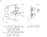
図1に示した方位探知アンテナA1の電力受信回路は、複数のアンテナ素子11−1、11−2及び受信電力合成部12を備える。図2に示した方位探知アンテナA1の電力受信回路は、図1に示した方位探知アンテナA1の電力受信回路に加えて、移相部17を更に備える。図3に示した方位探知アンテナA1の信号処理回路は、図1及び図2に示した方位探知アンテナA1の電力受信回路に対して共通して適用でき、電波到来角算出部13、放射源距離算出部14、データ受信部15及びデータ送信部16を備える。
The power receiving circuit of the direction finding antenna A1 shown in FIG. 1 includes a plurality of antenna elements 11-1 and 11-2 and a received
図1及び図2に示した複数のアンテナ素子11−1、11−2は、一次元方向(y方向)に配置される。図1及び図2の右欄に示したように、一次元方向(y方向)の電波到来角αyを、アンテナ素子11−2よりはアンテナ素子11−1の方に寄っているとすると、アンテナ素子11−2の受信位相に対するアンテナ素子11−1の受信位相の進み角Δθyは、数1のように表わされる。なお、dはアンテナ素子11−1とアンテナ素子11−2との間の素子間隔であり、λは真空中の電波の波長であり、lyはアンテナ素子11−1への光路長に対するアンテナ素子11−2への光路長の余剰長さである。
![]()
![]()
図1及び図2に示した受信電力合成部12は、「180°」と示した出力端子において、複数のアンテナ素子11−1、11−2の受信電力Y1、Y2の電力差Ydifを算出する。
1 and
ここで、図1に示した受信電力合成部12は、複数のアンテナ素子11−1、11−2の受信位相の位相差Δθyが更に移相されることなく、複数のアンテナ素子11−1、11−2の受信電力Y1、Y2の電力差Ydifを算出する。すると、複数のアンテナ素子11−1、11−2の受信電力Y1、Y2の電力差Ydifは、数2のように表わされる。なお、遠方界の近似が成立すると仮定すると、Y1=P1=Pr及びY2=P2=Prが成立する。
![]()
![]()
つまり、複数のアンテナ素子11−1、11−2の受信電力Y1、Y2の電力差Ydifは、アンテナの正面方向からの電波到来方向のずれ角度αyの変化に対して、ずれ角度αy=0°において極小となり、ずれ角度αy=0°について対称に大きく変化する。
That is, the power difference Y dif received
そこで、図3に示した電波到来角算出部13は、複数のアンテナ素子11−1、11−2の受信電力Y1、Y2の電力差Ydifに基づいて、一次元方向(y方向)の電波到来角αyを算出する。よって、一次元方向(y方向)の電波到来角αyの符号を算出することはできないが、一次元方向(y方向)の電波到来角αyの絶対値を精度高く算出することができる。なお、複数のアンテナ素子11−1、11−2の受信電力Y1、Y2の電力差Ydifを算出するのみならず、複数のアンテナ素子11−1、11−2の受信電力Y1、Y2の電力和Ysumを算出する必要があり、このことについては後に詳述する。
Therefore, the radio wave arrival
一方で、図2に示した受信電力合成部12は、複数のアンテナ素子11−1、11−2の受信位相の位相差Δθyが更に移相されたうえで、複数のアンテナ素子11−1、11−2の受信電力Y1、Y2の電力差Ydifを算出する。ただし、移相量θ>0°の移相部17の配置位置を、アンテナ素子11−1側とする。すると、複数のアンテナ素子11−1、11−2の受信電力Y1、Y2の電力差Ydifは、数3のように表わされる。なお、遠方界の近似が成立すると仮定すると、Y1=P1=Pr及びY2=P2=Prが成立する。
![]()
![]()
つまり、複数のアンテナ素子11−1、11−2の受信電力Y1、Y2の電力差Ydifは、アンテナの正面方向からの電波到来方向のずれ角度αyの変化に対して、有限のずれ角度αy≠0°において極小となり、ずれ角度αy=0°の近傍で単調に変化する。
That is, the power difference Y dif received
そこで、図3に示した電波到来角算出部13は、複数のアンテナ素子11−1、11−2の受信電力Y1、Y2の電力差Ydifに基づいて、一次元方向(y方向)の電波到来角αyを算出する。よって、一次元方向(y方向)の電波到来角αyの絶対値を算出することができるとともに、一次元方向(y方向)の電波到来角αyの符号を算出することができる。なお、複数のアンテナ素子11−1、11−2の受信電力Y1、Y2の電力差Ydifを算出するのみならず、複数のアンテナ素子11−1、11−2の受信電力Y1、Y2の電力和Ysumを算出する必要があり、このことについては後に詳述する。
Therefore, the radio wave arrival
図1及び図2に示した受信電力合成部12は、「0°」と示した出力端子において、複数のアンテナ素子11−1、11−2の受信電力Y1、Y2の電力和Ysumを算出する。
In the received
ここで、図1に示した受信電力合成部12は、複数のアンテナ素子11−1、11−2の受信位相の位相差Δθyが更に移相されることなく、複数のアンテナ素子11−1、11−2の受信電力Y1、Y2の電力和Ysumを算出する。すると、複数のアンテナ素子11−1、11−2の受信電力Y1、Y2の電力和Ysumは、数4のように表わされる。
![]()
![]()
一方で、図2に示した受信電力合成部12は、複数のアンテナ素子11−1、11−2の受信位相の位相差Δθyが更に移相されたうえで、複数のアンテナ素子11−1、11−2の受信電力Y1、Y2の電力和Ysumを算出する。すると、複数のアンテナ素子11−1、11−2の受信電力Y1、Y2の電力和Ysumは、数5のように表わされる。
![]()
![]()
つまり、複数のアンテナ素子11−1、11−2の受信電力Y1、Y2の電力和Ysumは、アンテナの正面方向からの電波到来方向のずれ角度αyの変化に対して、ずれ角度αy=0°の近傍でほぼ変化しない。このことは、複数のアンテナ素子11−1、11−2の受信位相の位相差Δθyが更に移相されるかどうかに関わらず、成立することである。 That is, the sum of the received powers Y 1 and Y 2 of the plurality of antenna elements 11-1 and 11-2 Y sum is the deviation angle with respect to the change of the deviation angle α y in the radio wave arrival direction from the front direction of the antenna. There is almost no change near α y = 0 °. This is true regardless of whether or not the phase difference Δθ y of the reception phases of the plurality of antenna elements 11-1 and 11-2 is further phase-shifted.
そこで、図3に示した放射源距離算出部14は、複数のアンテナ素子11−1、11−2の受信電力Y1、Y2の電力和Ysumと、電波放射源の既知の放射電力と、に基づいて、方位探知アンテナA1と電波放射源との間の距離を算出する。よって、方位探知アンテナA1から見た電波放射源の方位がアンテナの正面方向の近傍であれば、方位探知アンテナA1と電波放射源との間の距離を精度高く算出することができる。
Therefore, the radiation source distance calculation unit 14 shown in FIG. 3 includes the sum of the powers Y 1 and Y 2 of the received
そして、図3に示した電波到来角算出部13は、複数のアンテナ素子11−1、11−2の受信電力Y1、Y2の電力差Ydifと、方位探知アンテナA1と電波放射源との間の距離と、に基づいて、一次元方向(y方向)の電波到来角αyを算出する。
Then, the radio wave arrival
あるいは、図3に示した電波到来角算出部13は、複数のアンテナ素子11−1、11−2の受信電力Y1、Y2の電力差Ydifと、複数のアンテナ素子11−1、11−2の受信電力Y1、Y2の電力和Ysumと、の比Ydif/Ysumに基づいて、一次元方向(y方向)の電波到来角αyを算出する。その理由は、以下に示す通りである。
Alternatively, the radio wave arrival
というのは、複数のアンテナ素子11−1、11−2の受信電力Y1、Y2の電力差Ydifと、複数のアンテナ素子11−1、11−2の受信電力Y1、Y2の電力和Ysumは、電波放射源の放射電力及び方位探知アンテナA1と電波放射源との間の距離に依存する。しかし、これらの比Ydif/Ysumは、電波放射源の放射電力及び方位探知アンテナA1と電波放射源との間の距離に依存しない。これにより、電波放射源の放射電力及び方位探知アンテナA1と電波放射源との間の距離が未知でも、これらの比Ydif/Ysumに基づいて、一次元方向(y方向)の電波到来角αyを算出することができる。
Since the received
図3に示したデータ受信部15は、複数のアンテナ素子11−1、11−2の受信電力Y1、Y2の電力和Ysumにより、データ受信を行う。図3に示したデータ送信部16は、複数のアンテナ素子11−1、11−2の送信電力の電力和により、データ送信を行う。
The
ここで、複数のアンテナ素子11−1、11−2の受信電力Y1、Y2の電力和Ysumは、アンテナの正面方向からの電波到来方向のずれ角度αyの変化に対して、ずれ角度αy=0°の近傍でほぼ変化しない。そして、複数のアンテナ素子11−1、11−2の送信電力の電力和も、アンテナの正面方向からの電波放射方向のずれ角度αyの変化に対して、ずれ角度αy=0°の近傍でほぼ変化しない。よって、方位探知アンテナA1から見た電波放射源の方位がアンテナの正面方向の近傍であれば、方位探知アンテナA1と電波放射源との間のデータ受信及びデータ送信を実行することができる。 Here, the sum of the received powers Y 1 and Y 2 of the plurality of antenna elements 11-1 and 11-2 Y sum is deviated with respect to a change in the deviating angle α y in the radio wave arrival direction from the front direction of the antenna. There is almost no change near the angle α y = 0 °. The sum of the transmission powers of the plurality of antenna elements 11-1 and 11-2 is also in the vicinity of the deviation angle α y = 0 ° with respect to the change in the deviation angle α y in the radio wave radiation direction from the front direction of the antenna. There is almost no change in. Therefore, if the direction of the radio wave radiation source seen from the direction finding antenna A1 is near the front direction of the antenna, data reception and data transmission between the direction finding antenna A1 and the radio wave radiation source can be executed.
このように、電波到来角算出部13が、一次元方向(y方向)の電波到来角αyを算出するにあたり、方位探知アンテナA1は、位相モノパルスにおける位相判別回路を有する必要がなく、受信電力合成部12を有すれば足りる。よって、方位探知アンテナA1の回路構成を簡便にして、方位探知アンテナA1のコストを低くすることができる。
In this way, when the radio wave arrival
(第2実施形態の方位探知アンテナ)
第2実施形態の方位探知アンテナの電力受信回路の構成を図4から図6までに示す。第2実施形態の方位探知アンテナの信号処理回路の構成を図7に示す。
(Direction Detecting Antenna of the Second Embodiment)
The configuration of the power receiving circuit of the direction finding antenna of the second embodiment is shown in FIGS. 4 to 6. The configuration of the signal processing circuit of the direction finding antenna of the second embodiment is shown in FIG.
図4に示した方位探知アンテナA2の電力受信回路は、複数のアンテナ素子21−1、21−2、21−3、21−4及び受信電力合成部22−X、22−Yを備える。図5に示した方位探知アンテナA2の電力受信回路は、図4に示した方位探知アンテナA2の電力受信回路に加えて、移相部27−X、27−Yを更に備える。図6に示した方位探知アンテナA2の電力受信回路は、図4に示した方位探知アンテナA2の電力受信回路に加えて、移相部27−1、27−3、27−4を更に備える。図7に示した方位探知アンテナA2の信号処理回路は、図4から図6までに示した方位探知アンテナA2の電力受信回路に対して共通して適用でき、電波到来角算出部23、放射源距離算出部24、データ受信部25及びデータ送信部26を備える。
The power receiving circuit of the direction finding antenna A2 shown in FIG. 4 includes a plurality of antenna elements 21-1, 21-2, 21-3, 21-4 and received power combining units 22-X and 22-Y. The power receiving circuit of the direction finding antenna A2 shown in FIG. 5 further includes phase shifting units 27-X and 27-Y in addition to the power receiving circuit of the direction finding antenna A2 shown in FIG. The power receiving circuit of the direction finding antenna A2 shown in FIG. 6 further includes phase shifting units 27-1, 27-3, and 27-4 in addition to the power receiving circuit of the direction finding antenna A2 shown in FIG. The signal processing circuit of the direction-finding antenna A2 shown in FIG. 7 can be applied in common to the power receiving circuit of the direction-finding antenna A2 shown in FIGS. 4 to 6, and the radio wave arrival
図4から図6までに示した複数のアンテナ素子21−1、21−2、21−3、21−4は、二次元面内(xy平面内)に四角格子状に配置される。 The plurality of antenna elements 21-1, 21-2, 21-3, and 21-4 shown in FIGS. 4 to 6 are arranged in a two-dimensional plane (in the xy plane) in a square grid pattern.
図4から図6までの右欄に示したように、行方向(y方向)の電波到来角αyを、アンテナ素子21−2、21−4よりはアンテナ素子21−1、21−3の方に寄っているとすると、アンテナ素子21−2、21−4の受信位相に対するアンテナ素子21−1、21−3の受信位相の進み角Δθyは、数6のように表わされる。なお、dはアンテナ素子21−1、21−3とアンテナ素子21−2、21−4との間の素子間隔であり、λは真空中の電波の波長であり、lyはアンテナ素子21−1、21−3への光路長に対するアンテナ素子21−2、21−4への光路長の余剰長さである。
![]()
![]()
図4から図6までの上欄に示したように、列方向(x方向)の電波到来角αxを、アンテナ素子21−1、21−2よりはアンテナ素子21−3、21−4の方に寄っているとすると、アンテナ素子21−1、21−2の受信位相に対するアンテナ素子21−3、21−4の受信位相の進み角Δθxは、数7のように表わされる。なお、dはアンテナ素子21−1、21−2とアンテナ素子21−3、21−4との間の素子間隔であり、λは真空中の電波の波長であり、lyはアンテナ素子21−3、21−4への光路長に対するアンテナ素子21−1、21−2への光路長の余剰長さである。
![]()
![]()
図4から図6までに示した受信電力合成部22−Yは、「180°」と示した出力端子において、上行のアンテナ素子21−1、21−3の受信電力P1、P3の電力和Y1=(P1+P3)/2と、下行のアンテナ素子21−2、21−4の受信電力P2、P4の電力和Y2=(P2+P4)/2と、の行間差Ydif=|Y1−Y2|を算出する。
Receiving power combiner 22-Y shown in FIGS. 4 to 6, the output terminal indicated by "180 °", the received
ここで、図4に示した受信電力合成部22−Yは、上行と下行の電力和Y1、Y2の行間位相差Δθyが更に移相されることなく、上行と下行の電力和Y1、Y2の行間差Ydifを算出する。すると、上行と下行の電力和Y1、Y2の行間差Ydifは、数8のように表わされる。なお、遠方界の近似が成立すると仮定すると、P1=P2=P3=P4=Prが成立する。そして、図7に示した電波到来角算出部23は、上行と下行の電力和Y1、Y2の行間差Ydifに基づいて、行方向(y方向)の電波到来角αyを算出する。
![]()
![]()
一方で、図5及び図6に示した受信電力合成部22−Yは、上行と下行の電力和Y1、Y2の行間位相差Δθyが更に移相されたうえで、上行と下行の電力和Y1、Y2の行間差Ydifを算出する。ただし、移相量θ>0°の移相部27−Y、27−1、27−3の配置位置を、アンテナ素子21−1、21−3側とする。ここで、図5では、上行の受信電力P1、P3を合成したうえで、上行の電力和Y1を移相している。そして、図6では、上行の受信電力P1、P3を移相したうえで、上行の電力和Y1を算出している。すると、上行と下行の電力和Y1、Y2の行間差Ydifは、図5及び図6ではそれぞれ数9及び数10のように表わされる。なお、遠方界の近似が成立すると仮定すると、P1=P2=P3=P4=Prが成立する。そして、図7に示した電波到来角算出部23は、上行と下行の電力和Y1、Y2の行間差Ydifに基づいて、行方向(y方向)の電波到来角αyを算出する。
![]()
![]()
![]()
![]()
図4から図6までに示した受信電力合成部22−Xは、「180°」と示した出力端子において、左列のアンテナ素子21−1、21−2の受信電力P1、P2の電力和X1=(P1+P2)/2と、右列のアンテナ素子21−3、21−4の受信電力P3、P4の電力和X2=(P3+P4)/2と、の列間差Xdif=|X1−X2|を算出する。
Receiving power combiner 22-X shown in FIGS. 4 to 6, the output terminal indicated by "180 °", the antenna elements 21-1 and 21-2 in the left column of the received
ここで、図4に示した受信電力合成部22−Xは、左列と右列の電力和X1、X2の列間位相差Δθxが更に移相されることなく、左列と右列の電力和X1、X2の列間差Xdifを算出する。すると、左列と右列の電力和X1、X2の列間差Xdifは、数11のように表わされる。なお、遠方界の近似が成立すると仮定すると、P1=P2=P3=P4=Prが成立する。そして、図7に示した電波到来角算出部23は、左列と右列の電力和X1、X2の列間差Xdifに基づいて、列方向(x方向)の電波到来角αxを算出する。

一方で、図5及び図6に示した受信電力合成部22−Xは、左列と右列の電力和X1、X2の列間位相差Δθxが更に移相されたうえで、左列と右列の電力和X1、X2の列間差Xdifを算出する。ただし、移相量θ>0°の移相部27−X、27−3、27−4の配置位置を、アンテナ素子21−3、21−4側とする。ここで、図5では、右列の受信電力P3、P4を合成したうえで、右列の電力和X2を移相している。そして、図6では、右列の受信電力P3、P4を移相したうえで、右列の電力和X2を算出している。すると、左列と右列の電力和X1、X2の列間差Xdifは、図5及び図6ではそれぞれ数12及び数13のように表わされる。なお、遠方界の近似が成立すると仮定すると、P1=P2=P3=P4=Prが成立する。そして、図7に示した電波到来角算出部23は、左列と右列の電力和X1、X2の列間差Xdifに基づいて、列方向(x方向)の電波到来角αxを算出する。
![]()
![]()
図4から図6までに示した受信電力合成部22−Yは、「0°」と示した出力端子において、上行のアンテナ素子21−1、21−3の受信電力P1、P3の電力和Y1=(P1+P3)/2と、下行のアンテナ素子21−2、21−4の受信電力P2、P4の電力和Y2=(P2+P4)/2と、の行間和Ysum=Y1+Y2を算出する。
Receiving power combiner 22-Y shown in FIGS. 4 to 6, the output terminal indicated as "0 °", the received
ここで、図4に示した受信電力合成部22−Yは、上行と下行の電力和Y1、Y2の行間位相差Δθyが更に移相されることなく、上行と下行の電力和Y1、Y2の行間和Ysumを算出する。すると、上行と下行の電力和Y1、Y2の行間和Ysumは、数14のように表わされる。
![]()
![]()
一方で、図5及び図6に示した受信電力合成部22−Yは、上行と下行の電力和Y1、Y2の行間位相差Δθyが更に移相されたうえで、上行と下行の電力和Y1、Y2の行間和Ysumを算出する。すると、上行と下行の電力和Y1、Y2の行間和Ysumは、図5及び図6ではそれぞれ数15及び数16のように表わされる。
![]()
![]()
図4から図6までに示した受信電力合成部22−Xは、「0°」と示した出力端子において、左列のアンテナ素子21−1、21−2の受信電力P1、P2の電力和X1=(P1+P2)/2と、右列のアンテナ素子21−3、21−4の受信電力P3、P4の電力和X2=(P3+P4)/2と、の列間和Xsum=X1+X2を算出する。
Receiving power combiner 22-X shown in FIGS. 4 to 6, the output terminal indicated as "0 °", the antenna elements 21-1 and 21-2 in the left column of the received
ここで、図4に示した受信電力合成部22−Xは、左列と右列の電力和X1、X2の列間位相差Δθxが更に移相されることなく、左列と右列の電力和X1、X2の列間和Xsumを算出する。すると、左列と右列の電力和X1、X2の列間和Xsumは、数17のように表わされる。
![]()
![]()
一方で、図5及び図6に示した受信電力合成部22−Xは、左列と右列の電力和X1、X2の列間位相差Δθxが更に移相されたうえで、左列と右列の電力和X1、X2の列間和Xsumを算出する。すると、左列と右列の電力和X1、X2の列間和Xsumは、図5及び図6ではそれぞれ数18及び数19のように表わされる。
![]()
![]()
![]()
![]()
そして、図7に示した放射源距離算出部24は、複数のアンテナ素子21−1、21−2、21−3、21−4の受信電力P1、P2、P3、P4の電力和|P1+P2+P3+P4|=Xsum+Ysumと、電波放射源の既知の放射電力と、に基づいて、方位探知アンテナA2と電波放射源との間の距離を算出する。 Then, the radiation source distance calculation unit 24 shown in FIG. 7 has received powers P 1 , P 2 , P 3 , and P 4 of the plurality of antenna elements 21-1, 21-2, 21-3, and 21-4. The distance between the directional detection antenna A2 and the radio wave radiation source is calculated based on the sum | P 1 + P 2 + P 3 + P 4 | = X sum + Y sum and the known radiated power of the radio wave radiation source.
さらに、図7に示した電波到来角算出部23は、上行と下行の電力和Y1、Y2の行間差Ydifと、方位探知アンテナA2と電波放射源との間の距離と、に基づいて、行方向(y方向)の電波到来角αyを算出する。一方で、図7に示した電波到来角算出部23は、左列と右列の電力和X1、X2の列間差Xdifと、方位探知アンテナA2と電波放射源との間の距離と、に基づいて、列方向(x方向)の電波到来角αxを算出する。
Further, the radio wave arrival
あるいは、図7に示した電波到来角算出部23は、上行と下行の電力和Y1、Y2の行間差Ydifと、全電力和Xsum+Ysumと、の比Ydif/(Xsum+Ysum)に基づいて、行方向(y方向)の電波到来角αyを算出する。一方で、図7に示した電波到来角算出部23は、左列と右列の電力和X1、X2の列間差Xdifと、全電力和Xsum+Ysumと、の比Xdif/(Xsum+Ysum)に基づいて、列方向(x方向)の電波到来角αxを算出する。
Alternatively, the radio wave arrival
図7に示したデータ受信部25は、全電力和Xsum+Ysumにより、データ受信を行う。図7に示したデータ送信部26は、全電力和により、データ送信を行う。
The
第2実施形態の方位探知アンテナのうち、図4に示した方位探知アンテナA2(移相θがないとき)について、方位探知性能を図8に示す。実際の各アンテナ素子の指向性を考慮して、数8、11、14、17に示した電力値を計算した。自動車の衝突回避や宇宙船のドッキング等において、例えば−15°<αx、αy<15°を適用範囲とする。
Of the direction-finding antennas of the second embodiment, the direction-finding performance of the direction-finding antenna A2 (when there is no phase shift θ) shown in FIG. 4 is shown in FIG. The power values shown in
図8の上段には、全電力和Xsum+Ysumの指向性を示す。全電力和Xsum+Ysumは、アンテナの正面方向からの電波到来方向のずれ角度αx、αyの変化に対して、ずれ角度αx、αy=0°の近傍でほぼ変化しない。よって、方位探知アンテナA2から見た電波放射源の方位がアンテナの正面方向の近傍であれば、方位探知アンテナA2と電波放射源との間の距離を精度高く算出することができる。そして、方位探知アンテナA2から見た電波放射源の方位がアンテナの正面方向の近傍であれば、方位探知アンテナA2と電波放射源との間のデータ受信及びデータ送信を実行することができる。 The upper part of FIG. 8 shows the directivity of the total power sum X sum + Y sum. The total power sum X sum + Y sum hardly changes in the vicinity of the deviation angles α x and α y = 0 ° with respect to the changes in the deviation angles α x and α y in the direction of arrival of radio waves from the front direction of the antenna. Therefore, if the direction of the radio wave radiation source seen from the direction finding antenna A2 is near the front direction of the antenna, the distance between the direction finding antenna A2 and the radio wave radiation source can be calculated with high accuracy. Then, if the direction of the radio wave radiation source seen from the direction finding antenna A2 is near the front direction of the antenna, data reception and data transmission between the direction finding antenna A2 and the radio wave radiation source can be executed.
図8の中段には、列間差Xdif及び行間差Ydifの指向性を示す。列間差Xdif及び行間差Ydifは、アンテナの正面方向からの電波到来方向のずれ角度αx、αyの変化に対して、ずれ角度αx、αy=0°において極小となり、ずれ角度αx、αy=0°について対称に大きく変化する。よって、列/行方向(x/y方向)の電波到来角αx、αyの符号を算出することはできないが、列/行方向(x/y方向)の電波到来角αx、αyの絶対値を精度高く算出することができる。 The middle row of FIG. 8 shows the directivity of the column-to-column difference X- dim and the row-to-row difference Y- dif. The difference between columns X dim and the difference between rows Y dim are minimized at the deviation angles α x and α y = 0 ° with respect to changes in the deviation angles α x and α y in the direction of arrival of radio waves from the front direction of the antenna. It changes greatly symmetrically with respect to the angles α x and α y = 0 °. Therefore, it is not possible to calculate the sign of the radio wave arrival angles α x and α y in the column / row direction (x / y direction), but the radio wave arrival angles α x and α y in the column / row direction (x / y direction). The absolute value of can be calculated with high accuracy.
図8の下段には、Xdif/(Xsum+Ysum)及びYdif/(Xsum+Ysum)の指向性を示す。Xdif/(Xsum+Ysum)及びYdif/(Xsum+Ysum)は、電波放射源の放射電力及び方位探知アンテナA2と電波放射源との間の距離に依存しない。よって、電波放射源の放射電力及び方位探知アンテナA2と電波放射源との間の距離が未知でも、列/行方向(x/y方向)の電波到来角αx、αyの符号を算出することはできないが、列/行方向(x/y方向)の電波到来角αx、αyの絶対値を精度高く算出することができる。 The lower part of FIG. 8 shows the directivity of X dif / (X sum + Y sum ) and Y dif / (X sum + Y sum). X dif / (X sum + Y sum ) and Y dif / (X sum + Y sum ) do not depend on the radiated power of the radio source and the distance between the directional detection antenna A2 and the radio source. Therefore, even if the radiated power of the radio wave radiation source and the distance between the direction detection antenna A2 and the radio wave radiation source are unknown, the codes of the radio wave arrival angles α x and α y in the column / row direction (x / y direction) are calculated. Although this is not possible, the absolute values of the radio wave arrival angles α x and α y in the column / row direction (x / y direction) can be calculated with high accuracy.
第2実施形態の方位探知アンテナのうち、図5及び図6に示した方位探知アンテナA2(移相θがあるとき)について、方位探知性能を図9に示す。実際の各アンテナ素子の指向性を考慮して、数9、10、12、13、15、16、18、19に示した電力値を計算した。自動車の衝突回避や宇宙船のドッキング等において、例えば−15°<αx、αy<15°を適用範囲とする。
Of the direction-finding antennas of the second embodiment, the direction-finding performance of the direction-finding antenna A2 (when there is a phase shift θ) shown in FIGS. 5 and 6 is shown in FIG. The power values shown in
図9の上段には、全電力和Xsum+Ysumの指向性を示す。全電力和Xsum+Ysumは、アンテナの正面方向からの電波到来方向のずれ角度αx、αyの変化に対して、ずれ角度αx、αy=0°の近傍でほぼ変化しない。よって、方位探知アンテナA2から見た電波放射源の方位がアンテナの正面方向の近傍であれば、方位探知アンテナA2と電波放射源との間の距離を精度高く算出することができる。そして、方位探知アンテナA2から見た電波放射源の方位がアンテナの正面方向の近傍であれば、方位探知アンテナA2と電波放射源との間のデータ受信及びデータ送信を実行することができる。 The upper part of FIG. 9 shows the directivity of the total power sum X sum + Y sum. The total power sum X sum + Y sum hardly changes in the vicinity of the deviation angles α x and α y = 0 ° with respect to the changes in the deviation angles α x and α y in the direction of arrival of radio waves from the front direction of the antenna. Therefore, if the direction of the radio wave radiation source seen from the direction finding antenna A2 is near the front direction of the antenna, the distance between the direction finding antenna A2 and the radio wave radiation source can be calculated with high accuracy. Then, if the direction of the radio wave radiation source seen from the direction finding antenna A2 is near the front direction of the antenna, data reception and data transmission between the direction finding antenna A2 and the radio wave radiation source can be executed.
図9の中段には、列間差Xdif及び行間差Ydifの指向性を示す。列間差Xdif及び行間差Ydifは、アンテナの正面方向からの電波到来方向のずれ角度αx、αyの変化に対して、有限のずれ角度αx、αy≠0°において極小となり、ずれ角度αx、αy=0°の近傍で単調に変化する。よって、列/行方向(x/y方向)の電波到来角αx、αyの符号を算出することができるとともに、列/行方向(x/y方向)の電波到来角αx、αyの絶対値を算出することができる。 The middle row of FIG. 9 shows the directivity of the column-to-column difference X- dim and the row-to-row difference Y- dif. The inter-column difference X dif and the inter-row difference Y dif are minimized at finite deviation angles α x and α y ≠ 0 ° with respect to changes in the deviation angles α x and α y in the direction of arrival of radio waves from the front direction of the antenna. , The deviation angle changes monotonically near α x and α y = 0 °. Therefore, the radio wave arrival angle alpha x column / row direction (x / y-direction), alpha code it is possible to calculate the y, the radio wave arrival angle alpha x column / row direction (x / y-direction), alpha y The absolute value of can be calculated.
図9の下段には、Xdif/(Xsum+Ysum)及びYdif/(Xsum+Ysum)の指向性を示す。Xdif/(Xsum+Ysum)及びYdif/(Xsum+Ysum)は、電波放射源の放射電力及び方位探知アンテナA2と電波放射源との間の距離に依存しない。よって、電波放射源の放射電力及び方位探知アンテナA2と電波放射源との間の距離が未知でも、列/行方向(x/y方向)の電波到来角αx、αyの符号を算出することができるとともに、列/行方向(x/y方向)の電波到来角αx、αyの絶対値を算出することができる。 The lower part of FIG. 9 shows the directivity of X dif / (X sum + Y sum ) and Y dif / (X sum + Y sum). X dif / (X sum + Y sum ) and Y dif / (X sum + Y sum ) do not depend on the radiated power of the radio source and the distance between the directional detection antenna A2 and the radio source. Therefore, even if the radiated power of the radio wave radiation source and the distance between the direction detection antenna A2 and the radio wave radiation source are unknown, the codes of the radio wave arrival angles α x and α y in the column / row direction (x / y direction) are calculated. In addition, the absolute values of the radio wave arrival angles α x and α y in the column / row direction (x / y direction) can be calculated.
このように、電波到来角算出部23が、列/行方向(x/y方向)の電波到来角αx、αyを算出するにあたり、方位探知アンテナA2は、位相モノパルスにおける位相判別回路を有する必要がなく、受信電力合成部22−X、22−Yを有すれば足りる。よって、方位探知アンテナA2の回路構成を簡便にして、方位探知アンテナA2のコストを低くすることができる。
In this way, when the radio wave arrival
なお、複数のアンテナ素子として、3個のアンテナ素子21−1、21−2、21−3を配置するのみでも、列/行方向(x/y方向)の電波到来角αx、αyを算出することができるが、受信効率が1/2倍に低くなる割には、回路規模は3/4倍に小さくなるにすぎない。一方、複数のアンテナ素子として、4個のアンテナ素子21−1、21−2、21−3、21−4を配置するときには、回路規模は大きくなるものの、受信効率が高くなったうえで、列/行方向(x/y方向)の電波到来角αx、αyを算出することができる。 Even if only three antenna elements 21-1, 21-2, and 21-3 are arranged as a plurality of antenna elements, the radio wave arrival angles α x and α y in the column / row direction (x / y direction) can be set. Although it can be calculated, the circuit scale is only 3/4 times smaller than the reception efficiency is 1/2 times lower. On the other hand, when four antenna elements 21-1, 21-2, 21-3, and 21-4 are arranged as a plurality of antenna elements, the circuit scale becomes large, but the reception efficiency becomes high, and then the rows are arranged. The radio wave arrival angles α x and α y in the / row direction (x / y direction) can be calculated.
(変形例の方位探知アンテナ)
第2実施形態では、複数のアンテナ素子は、2行2列に配置されている。変形例として、複数のアンテナ素子は、m行n列(m、nは2以上の任意の整数)に配置されてもよい。このときには、隣接する行間/列間において、移相θを施せばよく、任意の行間/列間において、行間差Ydif及び列間差Xdifを算出すればよい。
(Modified example direction finding antenna)
In the second embodiment, the plurality of antenna elements are arranged in 2 rows and 2 columns. As a modification, the plurality of antenna elements may be arranged in m rows and n columns (m and n are arbitrary integers of 2 or more). At this time, the phase shift θ may be applied between adjacent rows / columns, and the row-to-row difference Y dif and the column-to-column difference X dif may be calculated at any row-to-column spacing.
第2実施形態では、複数のアンテナ素子は、四角格子状に配置されている。変形例として、複数のアンテナ素子は、三角格子状等に配置されてもよい。このときには、ある一つの配置方向を行方向とすればよく、60°隔てた配置方向を列方向とすればよい。 In the second embodiment, the plurality of antenna elements are arranged in a square grid pattern. As a modification, the plurality of antenna elements may be arranged in a triangular lattice pattern or the like. At this time, one arrangement direction may be the row direction, and the arrangement direction separated by 60 ° may be the column direction.
第1、2実施形態では、移相θを施さない処理と移相θを施す処理を、別個の電力受信回路を用いて実現している。変形例として、移相θを施さない処理と移相θを施す処理を、単一の電力受信回路において切替してもよい。移相θを施さない処理では、電波到来角の絶対値を精度高く算出することができ、移相θを施す処理では、電波到来角の符号を算出することができ、両方の処理の長所を併せ持つことができる。 In the first and second embodiments, the process of not performing the phase shift θ and the process of performing the phase shift θ are realized by using separate power receiving circuits. As a modification, the process of not performing the phase shift θ and the process of performing the phase shift θ may be switched in a single power receiving circuit. In the process without phase shift θ, the absolute value of the radio wave arrival angle can be calculated with high accuracy, and in the process with phase shift θ, the sign of the radio wave arrival angle can be calculated. You can have it together.
本開示の方位探知アンテナは、自動車の衝突回避のために、自車から見た他車の方位を算出する技術や、宇宙船のドッキングのために、自船から見た他船の方位を算出する技術等に、適用することができる。 The directional detection antenna of the present disclosure calculates the direction of another vehicle as seen from the own vehicle for avoiding a collision of a vehicle, and calculates the direction of another ship as seen from the own ship for docking a spacecraft. It can be applied to the technology to be used.
A1、A2:方位探知アンテナ
11−1、11−2、21−1、21−2、21−3、21−4:アンテナ素子
12、22−X、22−Y:受信電力合成部
13、23:電波到来角算出部
14、24:放射源距離算出部
15、25:データ受信部
16、26:データ送信部
17、27−X、27−Y、27−1、27−3、27−4:移相部
A1, A2: Direction finder antennas 11-1, 11-2, 21-1, 21-2, 21-3, 21-4:
Claims (10)
前記複数のアンテナ素子の受信電力の電力差を算出する受信電力差算出部と、
前記複数のアンテナ素子の受信電力の電力差に基づいて、前記一次元方向の電波到来角を算出する電波到来角算出部と、
を備えることを特徴とする方位探知アンテナ。 Multiple antenna elements arranged in one-dimensional direction,
A reception power difference calculation unit that calculates the power difference between the reception powers of the plurality of antenna elements, and a reception power difference calculation unit.
A radio wave arrival angle calculation unit that calculates the radio wave arrival angle in the one-dimensional direction based on the power difference between the received powers of the plurality of antenna elements.
A direction finder antenna characterized by being equipped with.
各行のアンテナ素子の受信電力の電力和の行間差を算出するとともに、各列のアンテナ素子の受信電力の電力和の列間差を算出する受信電力差算出部と、
前記各行のアンテナ素子の受信電力の電力和の行間差に基づいて、行方向の電波到来角を算出するとともに、前記各列のアンテナ素子の受信電力の電力和の列間差に基づいて、列方向の電波到来角を算出する電波到来角算出部と、
を備えることを特徴とする方位探知アンテナ。 Multiple antenna elements arranged in a two-dimensional plane,
A reception power difference calculation unit that calculates the difference between the rows of the sum of the received powers of the antenna elements in each row and the sum of the received powers of the antenna elements in each column.
The radio wave arrival angle in the row direction is calculated based on the difference between the rows of the sum of the received powers of the antenna elements in each row, and the columns are based on the difference between the rows of the sum of the received powers of the antenna elements in each row. A radio wave arrival angle calculation unit that calculates the direction radio wave arrival angle, and
A direction finder antenna characterized by being equipped with.
Priority Applications (1)
| Application Number | Priority Date | Filing Date | Title |
|---|---|---|---|
| JP2017228331A JP6910028B2 (en) | 2017-11-28 | 2017-11-28 | Direction finder antenna |
Applications Claiming Priority (1)
| Application Number | Priority Date | Filing Date | Title |
|---|---|---|---|
| JP2017228331A JP6910028B2 (en) | 2017-11-28 | 2017-11-28 | Direction finder antenna |
Publications (2)
| Publication Number | Publication Date |
|---|---|
| JP2019102844A JP2019102844A (en) | 2019-06-24 |
| JP6910028B2 true JP6910028B2 (en) | 2021-07-28 |
Family
ID=66977203
Family Applications (1)
| Application Number | Title | Priority Date | Filing Date |
|---|---|---|---|
| JP2017228331A Active JP6910028B2 (en) | 2017-11-28 | 2017-11-28 | Direction finder antenna |
Country Status (1)
| Country | Link |
|---|---|
| JP (1) | JP6910028B2 (en) |
Families Citing this family (3)
| Publication number | Priority date | Publication date | Assignee | Title |
|---|---|---|---|---|
| CN110687500B (en) * | 2019-10-28 | 2023-05-16 | 武汉大学 | Identification and positioning method and system for acquiring wireless signal arrival angle by intelligent antenna |
| JP6989663B1 (en) * | 2020-07-16 | 2022-01-05 | 株式会社東芝 | Radar device |
| CN114487995A (en) * | 2020-10-23 | 2022-05-13 | 上海华为技术有限公司 | Method for determining cell antenna azimuth angle, related device and equipment |
Family Cites Families (3)
| Publication number | Priority date | Publication date | Assignee | Title |
|---|---|---|---|---|
| JP2569925B2 (en) * | 1990-08-30 | 1997-01-08 | 三菱電機株式会社 | Array antenna |
| JPH06100643B2 (en) * | 1991-12-17 | 1994-12-12 | 宇宙開発事業団 | Monopulse tracking device |
| JP5227820B2 (en) * | 2009-01-26 | 2013-07-03 | 古河電気工業株式会社 | Radar system antenna |
-
2017
- 2017-11-28 JP JP2017228331A patent/JP6910028B2/en active Active
Also Published As
| Publication number | Publication date |
|---|---|
| JP2019102844A (en) | 2019-06-24 |
Similar Documents
| Publication | Publication Date | Title |
|---|---|---|
| CN108701907B (en) | MIMO radar device, vehicle and antenna system | |
| JP6910028B2 (en) | Direction finder antenna | |
| US7705779B2 (en) | Wireless communication apparatus for determining direction of arrival information to form a three-dimensional beam used by a transceiver | |
| CN114280593B (en) | Radar system and vehicle | |
| US6067048A (en) | Radar apparatus | |
| JP7224174B2 (en) | Electronic device and radar control method | |
| CN108780950B (en) | Antenna arrangement for a radar sensor | |
| JP2022062063A (en) | Antenna arrays | |
| EP3109939B1 (en) | Dual-band phased array antenna with built-in grating lobe mitigation | |
| EP3271968B1 (en) | An amplitude comparison monopulse radar system | |
| EP3258540B1 (en) | Planar antenna array | |
| US11500059B2 (en) | Radar device | |
| JP2019174246A (en) | Radar device | |
| WO2023138110A1 (en) | Antenna, radar, and antenna adjustment method | |
| US11217897B1 (en) | Antenna system and method with a hybrid beamformer architecture | |
| JP2009031185A (en) | Radar system and target detecting method | |
| NO865029L (en) | ARRIVAL ANTENNA OF THE LEAK TYPE. | |
| US11367954B1 (en) | Multibeam cross bar electronically scanned array | |
| US20200072960A1 (en) | Radar device and detection method of target position of radar device | |
| CN113848527A (en) | High-precision interferometer | |
| JP6338427B2 (en) | Radar power supply circuit | |
| CN112368591A (en) | Radar apparatus | |
| Tamura et al. | A Planar Direction-Finding Antenna with Reconfigurable Circuit for Scan Range Extension | |
| WO2024135327A1 (en) | Electronic device and transmission/reception system | |
| CN103579759A (en) | Method for achieving omni-directional coverage of wave beams of array antenna |
Legal Events
| Date | Code | Title | Description |
|---|---|---|---|
| A521 | Request for written amendment filed |
Free format text: JAPANESE INTERMEDIATE CODE: A523 Effective date: 20171219 |
|
| A621 | Written request for application examination |
Free format text: JAPANESE INTERMEDIATE CODE: A621 Effective date: 20200713 |
|
| A977 | Report on retrieval |
Free format text: JAPANESE INTERMEDIATE CODE: A971007 Effective date: 20210414 |
|
| TRDD | Decision of grant or rejection written | ||
| A01 | Written decision to grant a patent or to grant a registration (utility model) |
Free format text: JAPANESE INTERMEDIATE CODE: A01 Effective date: 20210615 |
|
| A61 | First payment of annual fees (during grant procedure) |
Free format text: JAPANESE INTERMEDIATE CODE: A61 Effective date: 20210625 |
|
| R150 | Certificate of patent or registration of utility model |
Ref document number: 6910028 Country of ref document: JP Free format text: JAPANESE INTERMEDIATE CODE: R150 |
|
| R250 | Receipt of annual fees |
Free format text: JAPANESE INTERMEDIATE CODE: R250 |