JP6908624B2 - Systems and methods for real-time volume control - Google Patents
Systems and methods for real-time volume control Download PDFInfo
- Publication number
- JP6908624B2 JP6908624B2 JP2018554524A JP2018554524A JP6908624B2 JP 6908624 B2 JP6908624 B2 JP 6908624B2 JP 2018554524 A JP2018554524 A JP 2018554524A JP 2018554524 A JP2018554524 A JP 2018554524A JP 6908624 B2 JP6908624 B2 JP 6908624B2
- Authority
- JP
- Japan
- Prior art keywords
- fluid
- volume
- cover glass
- substrate
- image
- Prior art date
- Legal status (The legal status is an assumption and is not a legal conclusion. Google has not performed a legal analysis and makes no representation as to the accuracy of the status listed.)
- Active
Links
Images


Classifications
-
- G—PHYSICS
- G01—MEASURING; TESTING
- G01N—INVESTIGATING OR ANALYSING MATERIALS BY DETERMINING THEIR CHEMICAL OR PHYSICAL PROPERTIES
- G01N1/00—Sampling; Preparing specimens for investigation
- G01N1/28—Preparing specimens for investigation including physical details of (bio-)chemical methods covered elsewhere, e.g. G01N33/50, C12Q
- G01N1/2813—Producing thin layers of samples on a substrate, e.g. smearing, spinning-on
-
- G—PHYSICS
- G01—MEASURING; TESTING
- G01N—INVESTIGATING OR ANALYSING MATERIALS BY DETERMINING THEIR CHEMICAL OR PHYSICAL PROPERTIES
- G01N35/00—Automatic analysis not limited to methods or materials provided for in any single one of groups G01N1/00 - G01N33/00; Handling materials therefor
- G01N35/00584—Control arrangements for automatic analysers
- G01N35/00594—Quality control, including calibration or testing of components of the analyser
- G01N35/00613—Quality control
- G01N35/00663—Quality control of consumables
-
- G—PHYSICS
- G01—MEASURING; TESTING
- G01N—INVESTIGATING OR ANALYSING MATERIALS BY DETERMINING THEIR CHEMICAL OR PHYSICAL PROPERTIES
- G01N35/00—Automatic analysis not limited to methods or materials provided for in any single one of groups G01N1/00 - G01N33/00; Handling materials therefor
- G01N35/10—Devices for transferring samples or any liquids to, in, or from, the analysis apparatus, e.g. suction devices, injection devices
- G01N35/1009—Characterised by arrangements for controlling the aspiration or dispense of liquids
-
- G—PHYSICS
- G06—COMPUTING; CALCULATING OR COUNTING
- G06T—IMAGE DATA PROCESSING OR GENERATION, IN GENERAL
- G06T7/00—Image analysis
- G06T7/0002—Inspection of images, e.g. flaw detection
- G06T7/0012—Biomedical image inspection
-
- G—PHYSICS
- G06—COMPUTING; CALCULATING OR COUNTING
- G06T—IMAGE DATA PROCESSING OR GENERATION, IN GENERAL
- G06T7/00—Image analysis
- G06T7/20—Analysis of motion
- G06T7/246—Analysis of motion using feature-based methods, e.g. the tracking of corners or segments
-
- G—PHYSICS
- G06—COMPUTING; CALCULATING OR COUNTING
- G06T—IMAGE DATA PROCESSING OR GENERATION, IN GENERAL
- G06T7/00—Image analysis
- G06T7/60—Analysis of geometric attributes
- G06T7/62—Analysis of geometric attributes of area, perimeter, diameter or volume
-
- G—PHYSICS
- G01—MEASURING; TESTING
- G01N—INVESTIGATING OR ANALYSING MATERIALS BY DETERMINING THEIR CHEMICAL OR PHYSICAL PROPERTIES
- G01N1/00—Sampling; Preparing specimens for investigation
- G01N1/28—Preparing specimens for investigation including physical details of (bio-)chemical methods covered elsewhere, e.g. G01N33/50, C12Q
- G01N1/2813—Producing thin layers of samples on a substrate, e.g. smearing, spinning-on
- G01N2001/282—Producing thin layers of samples on a substrate, e.g. smearing, spinning-on with mapping; Identification of areas; Spatial correlated pattern
-
- G—PHYSICS
- G01—MEASURING; TESTING
- G01N—INVESTIGATING OR ANALYSING MATERIALS BY DETERMINING THEIR CHEMICAL OR PHYSICAL PROPERTIES
- G01N35/00—Automatic analysis not limited to methods or materials provided for in any single one of groups G01N1/00 - G01N33/00; Handling materials therefor
- G01N35/00584—Control arrangements for automatic analysers
- G01N35/00594—Quality control, including calibration or testing of components of the analyser
- G01N35/00613—Quality control
- G01N35/00663—Quality control of consumables
- G01N2035/00673—Quality control of consumables of reagents
-
- G—PHYSICS
- G01—MEASURING; TESTING
- G01N—INVESTIGATING OR ANALYSING MATERIALS BY DETERMINING THEIR CHEMICAL OR PHYSICAL PROPERTIES
- G01N35/00—Automatic analysis not limited to methods or materials provided for in any single one of groups G01N1/00 - G01N33/00; Handling materials therefor
- G01N35/10—Devices for transferring samples or any liquids to, in, or from, the analysis apparatus, e.g. suction devices, injection devices
- G01N35/1009—Characterised by arrangements for controlling the aspiration or dispense of liquids
- G01N2035/1025—Fluid level sensing
-
- G—PHYSICS
- G06—COMPUTING; CALCULATING OR COUNTING
- G06T—IMAGE DATA PROCESSING OR GENERATION, IN GENERAL
- G06T2207/00—Indexing scheme for image analysis or image enhancement
- G06T2207/30—Subject of image; Context of image processing
- G06T2207/30168—Image quality inspection
Description
関連出願データ
[0001]本開示は、内容が本明細書に参照により組み込まれる、2016年4月27日に提出された米国仮特許出願第62/328,254号の利益を主張するものである。
Related application data
[0001] The present disclosure claims the benefit of US Provisional Patent Application No. 62 / 328,254 filed April 27, 2016, the contents of which are incorporated herein by reference.
[0002]本発明は、試薬量検知用のシステムおよび方法に関し、詳細には、組織染色処理中のスライドガラス上の試薬量検知用のシステムおよび方法に関する。 [0002] The present invention relates to a system and method for detecting the amount of reagent, and more particularly to a system and method for detecting the amount of reagent on a slide glass during a tissue staining process.
[0003]生物学的検定法は、生体標本に関連付けられた1つまたは複数の特性、たとえば、その分子含有量または細胞構造などを、測定または観察するために実行され得る解析手順である。たとえば、組織切片および細胞試料などの細胞標本は、それらが基板上に支持されている間、1つまたは複数の流体を標本に塗布することによって、顕微鏡分析のために準備され得る。顕微鏡スライドガラスが支持する細胞標本は、多くの場合、着色するために1つまたは複数の染料または他の試薬で処理され、他の透明なまたは不可視の細胞および細胞の成分と対比される。免疫組織化学的(IHC)および原位置ハイブリッド形成法(ISH)染色法は、標本内部のタンパク質および核酸それぞれの存在、位置、および分布を明瞭化するために、細胞標本の処理に使用され得る。 [0003] A biological assay is an analytical procedure that can be performed to measure or observe one or more properties associated with a biological specimen, such as its molecular content or cell structure. For example, cell specimens such as tissue sections and cell samples can be prepared for microscopic analysis by applying one or more fluids to the specimen while they are supported on the substrate. Cell specimens supported by microscope slides are often treated with one or more dyes or other reagents for coloring and contrasted with other clear or invisible cells and cell components. Immunohistochemical (IHC) and in-situ hybrid formation (ISH) staining methods can be used in the processing of cell specimens to clarify the presence, location, and distribution of each protein and nucleic acid within the specimen.
[0004]分析およびプラットフォーム構築および商業的分析試験は、再現性および精度が、現在は病理学者の評価によって安定化されるため、時間および資源の点から費用がかかり得る。スライドガラスに基づく分析の成功は、一定のISH分析に12時間以上かかり得る分析の完了後にようやく、病理学者によって、さらに時間を要する多標的プロトコルを用いて評価される。組織染色処理での任意の混乱または不整合は、その後にようやく発見され、多くの場合、正確な原因には広範な追加分析が必要となる。全体的に、そのような処理は、浪費される高価な組織試料、および増加する開発時間とその付随するコストに関して、問題を生み出す。 [0004] Analytical and platform-building and commercial analytical trials can be costly in terms of time and resources, as reproducibility and accuracy are now stabilized by pathologists' assessments. Successful slide glass-based analysis is assessed by pathologists using a more time-consuming multi-target protocol only after completion of the analysis, which can take 12 hours or more for a given ISH analysis. Any confusion or inconsistency in the tissue staining process is only discovered thereafter and often requires extensive additional analysis for the exact cause. Overall, such processing creates problems with respect to wasted expensive tissue samples and increased development time and associated costs.
[0005]試薬流体の蒸発は、試薬濃度の変化を生じさせ得るメカニズムの1つである。たとえば、試薬からの溶媒の蒸発は、特に試薬流体の体積の縁部において、試薬成分の濃度の増加をもたらし得る。同様に、分析中の生体試料による試薬成分の取り込みも、1つまたは複数の試薬成分の局在的な枯渇の原因となり得る。この取り込みは、たとえば組織試料全体で不均一であり得るので、濃度勾配が発生し得て、1つまたは複数のそのような勾配に沿った染色度合いの差を生じさせ得る。さらに、濃度が増加するにつれて、通常、取り込みおよび他の相互作用ならびに反応が加速するので、蒸発は、こう配および不均一な染色の原因となり得る。全体的に、時間的および空間的な試薬濃度の変化は、組織試料全体の不均一な染色という結果をもたらし得る。蒸発の場合、組織が部分的にまたは全体的に乾燥し、組織試料が使用不能になることもあり得る。原因に関係なく、濃度変化または組織損傷を判定するために、病理学者の分析を待たねばならないことは、多大な浪費時間と、高価および/または希少な試料のさらなる消費とに、つながることになる。 [0005] Evaporation of reagent fluid is one of the mechanisms that can cause changes in reagent concentration. For example, evaporation of the solvent from the reagent can result in an increase in the concentration of reagent components, especially at the edges of the volume of the reagent fluid. Similarly, the uptake of reagent components by a biological sample under analysis can also cause localized depletion of one or more reagent components. Since this uptake can be non-uniform throughout the tissue sample, for example, concentration gradients can occur, causing differences in the degree of staining along one or more such gradients. In addition, evaporation can cause gradients and heterogeneous staining, as uptake and other interactions and reactions usually accelerate as the concentration increases. Overall, changes in reagent concentration over time and space can result in non-uniform staining of the entire tissue sample. In the case of evaporation, the tissue may become partially or wholly dry, making the tissue sample unusable. Having to wait for a pathologist's analysis to determine concentration changes or tissue damage, regardless of cause, can lead to significant wasted time and further consumption of expensive and / or rare samples. ..
[0006]商業的分析を商業的計器で実行した後、分析の成功は、病理学者によって評価されることになる。トラブルシューティング指針および彼ら自身の知識を用いることで、病理学者は、試験所へ分析を実行するフィードバックを提供し、新しい試料を要求することができる。再び、このことは、相当な遅延につながるが、この場合、遅延は、患者が、彼らの生活の質に非常に密接に影響を与え得る結果を受け取るのに要する時間に影響する。 [0006] After performing a commercial analysis on a commercial instrument, the success of the analysis will be assessed by a pathologist. Using troubleshooting guidelines and their own knowledge, pathologists can provide the laboratory with feedback to perform the analysis and request new samples. Again, this leads to a considerable delay, in which case the delay affects the time it takes for patients to receive results that can have a very close impact on their quality of life.
[0007]処理中の蒸発を軽減するための現在の解決策は、局所的な湿度および温度に依存する概算蒸発速度に基づいた流体の補給に頼っている。湿度および温度は、分析処理時間中に変動し得るので、そのような試薬の概算補給速度は、正確でない可能性がある。さらに、補給速度は、スライドガラス毎に決定されないし、リアルタイムでも決定されない。したがって、流体体積を検知し、かつリアルタイムで正確な液体補給を提供する、方法およびシステムが必要である。 [0007] Current solutions to mitigate evaporation during processing rely on fluid replenishment based on an approximate evaporation rate that depends on local humidity and temperature. Approximate replenishment rates for such reagents may not be accurate, as humidity and temperature can fluctuate during the analytical process. Furthermore, the replenishment rate is not determined for each glass slide, nor is it determined in real time. Therefore, there is a need for methods and systems that detect fluid volume and provide accurate liquid replenishment in real time.
本願発明の一実施例は、例えば、リアルタイム体積制御するためのシステムおよび方法に関する。 One embodiment of the present invention relates to, for example, a system and method for real-time volume control.
[0008]本明細書で開示されるのは、流体体積を検知し、かつリアルタイムで液体補給を提供する、方法、コンピュータプログラム製品、およびシステムであり、その結果、分析結果を損ねかねない処理条件が、未然に回避される。さらに、開示される方法、プログラム製品、およびシステムは、病理学者が処理過失発生を判定する、試料試験の完了を待たなくてもよいように、支援し得る。 [0008] Disclosed herein are methods, computer program products, and systems that detect fluid volume and provide liquid replenishment in real time, resulting in processing conditions that can compromise analytical results. However, it is avoided before it happens. In addition, the disclosed methods, program products, and systems may assist pathologists in determining the occurrence of processing errors without having to wait for the completion of sample testing.
[0009]一態様によれば、分析中の生体試料を保持する基板上に分配されることになる、流体補給量の概算方法が開示される。本方法は、撮影画像を生成するために撮像システムを用いて、(顕微鏡のスライドガラス上に載せられた組織または細胞学試料などの)生体試料を保持する基板上に分配される流体の画像を撮影することを含む。特に、流体は、向かい合わされる表面が、分析ステップが実行される(毛管現象空間のような)小体積空間を形成するように基板から一定の間隔を置かれた薄膜染色システムのように、基板とカバーガラスとの間に閉じ込められ得る。撮影画像は、基板上に分配され、基板とカバーガラスとの間の空間に閉じ込められた流体の流体境界を識別するために(たとえば画像分析方法によって)分析される。識別される流体境界は、次に基板上に分配された流体体積を計算するために使用され得る、流体幅を提供する。たとえば、決定された幅は、既知の体積に対応する流体幅を測定し、一次(線形)関数などの関数との関係にフィッティングすることによって作成された検量線と比較されてもよい。別法として、基板とカバーガラスとの間の空間の幾何学的寸法が、観察された幅と共に、体積の計算に用いられてもよい。流体体積の計算方法に関係なく、この計算流体体積は、追加流体が追加されるべきか否か判定し、たとえば蒸発、または逃散ならびに漏洩などの他の任意の過程による、流体損失を補給するために、どれだけの量が追加されるべきか決定するために使用され得る。流体の補給量は、所定の体積と計算流体体積とを比較することによって、計算されてもよく、計算流体体積と所定の体積との差分が、補給量を提供する。具体的な実施形態では、方法は、補給量だけ流体体積を補給するステップをさらに含む。この方法では、任意の流体損失は、置換され得て、それにより分析中、十分な試薬などの流体と、生体試料との接触の保証を支援する。生体試料と接触する適切な流体量の維持は、結果として、計画通りの分析進行の補償を支援し、全ての分析プロセスが完了してはじめて(乾燥組織などの)問題が発見されるとすると、他に発生するかもしれない分析結果を提供することで、遅延を回避し得る。 [0009] According to one aspect, a method of estimating the amount of fluid replenishment that will be distributed on the substrate holding the biological sample being analyzed is disclosed. The method uses an imaging system to generate an image of the fluid distributed on a substrate holding a biological sample (such as a tissue or cytology sample placed on a microscope slide). Including shooting. In particular, the fluid is a substrate, such as a thin film staining system, where the facing surfaces form a small volume space (such as a capillary space) on which the analytical steps are performed. Can be trapped between and the cover glass. The captured image is distributed on the substrate and analyzed (eg, by an image analysis method) to identify the fluid boundary of the fluid confined in the space between the substrate and the cover glass. The identified fluid boundary provides a fluid width that can then be used to calculate the volume of fluid distributed on the substrate. For example, the determined width may be compared to a calibration curve created by measuring the fluid width corresponding to a known volume and fitting it in relation to a function such as a linear function. Alternatively, the geometric dimensions of the space between the substrate and the cover glass may be used in the volume calculation, along with the observed width. Regardless of how the fluid volume is calculated, this computational fluid volume is used to determine if additional fluid should be added and to compensate for fluid loss due to any other process, such as evaporation, or escape and leakage. Can be used to determine how much should be added to. The fluid replenishment amount may be calculated by comparing a predetermined volume with the calculated fluid volume, and the difference between the calculated fluid volume and the predetermined volume provides the replenishment amount. In a specific embodiment, the method further comprises the step of replenishing the fluid volume by the replenishment amount. In this method, any fluid loss can be replaced, thereby assisting in ensuring contact between the fluid, such as sufficient reagents, and the biological sample during analysis. Maintaining the proper amount of fluid in contact with the biological sample will, as a result, help compensate for the planned progress of the analysis, and only after the entire analytical process has been completed will problems (such as dry tissue) be discovered. Delays can be avoided by providing other analysis results that may occur.
[0010]別の態様では、分析中の生体試料を含む基板上に、詳細には流体が基板とカバーガラスとの間の空間に閉じ込められたところに、分配される流体補給量を概算するシステムが開示される。全体システムは、基板およびカバーガラス上に配置されたカメラと、少なくとも2つの光源とをそれ自体が含む、画像取得記憶システムを含む。第1の光源は、第1の光源から発せられる第1の光が、カメラの視野(FOV)内にあるように位置決めされ、第2の光源は、第2の光源から発せられる第2の光が、カメラの視野外にあるように位置決めされる。撮像配置は、それにより暗視野撮像を支援するように構成される。画像分析システムは、画像取得記憶システムに動作可能に結合されたプロセッサと、プロセッサによって実行されるとき、プロセッサに一定の動作を実行させる、デジタルコード化された命令を記憶するように構成されたプロセッサに動作可能に結合されたメモリとをさらに含む。動作は、撮影画像を生成するためにカメラを使用して、生体試料を保持する基板上に分配される流体の画像を撮影することと、基板上に分配され、基板とカバーガラスとの間の空間に閉じ込められた流体の流体境界を識別するために撮影画像を解析することと、流体境界から決定された流体幅を使用して、基板上に分配された流体の流体体積を計算することと、計算流体体積および所定の流体体積に基づいて流体の補給量を計算することとを含む。ある実施形態では、流体体積を所定の体積に復帰させるために、たとえば自動的に、プロセッサの制御下で、メモリが補給ディスペンサを制御する命令をさらに記憶して、補給量は、システムの補給ディスペンサを使用して追加される。 [0010] In another aspect, a system that estimates the amount of fluid replenishment distributed on a substrate containing a biological sample being analyzed, specifically where the fluid is confined in the space between the substrate and the cover glass. Is disclosed. The overall system includes an image acquisition and storage system that itself includes a camera arranged on a substrate and a cover glass, and at least two light sources. The first light source is positioned so that the first light emitted from the first light source is within the field of view (FOV) of the camera, and the second light source is the second light emitted from the second light source. Is positioned so that it is out of the field of view of the camera. The imaging arrangement is thereby configured to support darkfield imaging. An image analysis system is a processor operably coupled to an image acquisition and storage system and a processor configured to store digitally coded instructions that cause the processor to perform certain actions when executed by the processor. Also includes memory that is operably combined with. The operation is to use a camera to generate a captured image, to capture an image of the fluid distributed on the substrate holding the biological sample, and to be distributed on the substrate and between the substrate and the cover glass. Analyzing captured images to identify the fluid boundaries of fluids confined in space, and using the fluid width determined from the fluid boundaries to calculate the fluid volume of the fluid distributed on the substrate. , Includes calculating the amount of fluid replenishment based on the calculated fluid volume and a given fluid volume. In one embodiment, in order to return the fluid volume to a predetermined volume, for example, automatically, under the control of the processor, the memory further stores instructions to control the replenishment dispenser, and the replenishment amount is the system's replenishment dispenser. Is added using.
[0011]具体的な実施形態では、流体境界の縁部を照明する暗視野撮像の使用、および/または動作中の流体境界を検出する前景動作検出の使用、および/または着色された流体の検出を支援する色しきい値の使用、の全てが合同して、流体幅の検出を確実に支援し、最小限の誤差で(たとえば約1.5%未満の誤差で)リアルタイムに多種多様な流体の計算流体体積を提供する。そのうえ、開示された方法およびシステムは堅牢であり、システム内の分析は、ディスペンサの動作などの他のシステムの動作、組織の色の変化、および機器の振動によって影響されない。 [0011] In a specific embodiment, the use of dark-field imaging to illuminate the edges of the fluid boundary, and / or the use of foreground motion detection to detect the fluid boundary in motion, and / or the detection of colored fluid. The use of color thresholds, all in combination, ensures that fluid width detection is assisted and a wide variety of fluids in real time with minimal error (eg less than about 1.5% error). Provides the computational fluid volume of. Moreover, the disclosed methods and systems are robust and the analysis within the system is unaffected by the behavior of other systems such as dispenser behavior, tissue color changes, and instrument vibration.
[0012]他の態様では、開示されたシステムに開示された方法を実行させる命令と、開示された方法を実行する命令を記憶する(非一時的な)コンピュータ可読媒体と、を含むコンピュータプログラム製品が提供される。 [0012] In another aspect, a computer program product comprising an instruction to cause the disclosed system to perform the disclosed method and a (non-temporary) computer-readable medium storing the instruction to perform the disclosed method. Is provided.
[0013]追加の実施形態および態様が、添付図面に関連して提供される以下の詳細な説明の考察から明らかになるであろう。 [0013] Additional embodiments and embodiments will become apparent from the discussion of the following detailed description provided in connection with the accompanying drawings.
[0033]本明細書で説明する特徴または特徴の組合せは、任意のそのような組合せに含まれる特徴が相互に矛盾しないという条件のもと、文脈、本明細書、およびある当業者の知識から明らかになるように、本開示の範囲内に含まれる。付加的な利点および態様は、以下の詳細な明細書および請求項を考慮することで明らかになるであろう。 [0033] The features or combinations of features described herein are from the context, the specification, and the knowledge of one of ordinary skill in the art, provided that the features contained in any such combination are consistent with each other. As will be apparent, it is included within the scope of this disclosure. Additional benefits and aspects will become apparent by considering the detailed description and claims below.
[0034]一態様では、分析中の生体試料を保持する基板上に分配されることになる流体の補給量の概算方法が開示される。方法は、撮影画像を生成するために撮像システムを使用して、生体試料を保持する基板上に分配される流体の画像を撮影するステップであって、流体が基板とカバーガラスとの間の空間に閉じ込められているステップと、基板上に分配され、基板とカバーガラスとの間の空間に閉じ込められた流体の流体境界を識別するために撮影画像を解析するステップと、流体境界から決定された流体幅を使用して、基板上に分配された流体の流体体積を計算するステップと、計算流体体積および所定の流体体積に基づいて流体の補給量を計算するステップとを含む。 [0034] In one aspect, a method of estimating the amount of fluid replenishment that will be distributed on the substrate holding the biological sample being analyzed is disclosed. The method is the step of taking an image of the fluid distributed on the substrate holding the biological sample using an imaging system to generate the captured image, in which the fluid is the space between the substrate and the cover glass. Determined from the steps confined in the fluid, the steps to analyze the captured image to identify the fluid boundaries of the fluid distributed on the substrate and confined in the space between the substrate and the cover glass, and the fluid boundaries. It includes the step of calculating the fluid volume of the fluid distributed on the substrate using the fluid width and the step of calculating the replenishment amount of the fluid based on the calculated fluid volume and a predetermined fluid volume.
[0035]本明細書で使用されるように、「流体幅」は、カバーガラスと下層の基板との間の空間内にある液体の1つまたは複数の観察される幅を示し、より一般には、撮影画像内で観察されるような液体によって占有される面積の計算を可能にする1つまたは複数の測定値を示す。その最も単純な形状では、流体は、カバーガラス下に正方形または長方形の形状を占有すると見ることができ、液体の測定された単一の幅は、カバーガラスと基板との間の空間の既知の形状に基づいた体積計算を支援するのに十分である。別法として、単一の幅は、既知の体積を空間に置き、観察される対応する幅を測定することによって作成される検量線と共に利用され得る。「流体幅」対体積の関係への数学的なフィッティング(一次またはそれ以上の関数、対数、指数関数、および他の周知のカーブフィッティング関数など)は、その上で計算体積が測定済みの流体幅から決定され得る検量線を提供し得る。流体は、流体の基板との相互作用に応じて、または流体がたとえば蒸発によって流体がなくなるようにカバーガラスと基板との間の空間から引き離されるので、通常、卵形または他の幾何学的形状のように見え得る可能性もある。したがって、画像は、1つまたは複数の方向のいくつかの幅から流体本体の複数の部分の体積を計算し、計算体積を提供するためにそれらを組み合わせるための原理を提供し得る。全くさらに洗練された実施形態では、カバーガラスと下層の基板との間の空間内の流体によって占有される面積は、液体本体または本体の集合が画像分析方法によって分離され得る一連の幾何学的形状の面積を合計することによって決定され得る。全体的に、カバーガラスと基板との間の空間の形状の図形は、空間内の流体の体積を概算するために、1つまたは複数の「流体幅」の組合せで決定され、使用され得る。 [0035] As used herein, "fluid width" refers to the observed width of one or more liquids in the space between the cover glass and the underlying substrate, more generally. , One or more measurements that allow the calculation of the area occupied by the liquid as observed in the captured image. In its simplest shape, the fluid can be seen occupying a square or rectangular shape under the cover glass, and the measured single width of the liquid is a known single width of space between the cover glass and the substrate. Sufficient to support shape-based volumetric calculations. Alternatively, a single width can be utilized with a calibration curve created by placing a known volume in space and measuring the corresponding width observed. Mathematical fitting to a "fluid width" vs. volume relationship (such as linear or higher functions, logarithmic, exponential, and other well-known curve fitting functions) is a fluid width whose calculated volume has been measured on it. It may provide a calibration line that can be determined from. The fluid is usually oval or other geometric shape because it is pulled away from the space between the cover glass and the substrate in response to the interaction of the fluid with the substrate or so that the fluid is eliminated by, for example, evaporation. It may look like. Therefore, an image may provide a principle for calculating the volume of multiple parts of a fluid body from several widths in one or more directions and combining them to provide the calculated volume. In a completely more sophisticated embodiment, the area occupied by the fluid in the space between the cover glass and the underlying substrate is a series of geometric shapes in which the liquid body or body assembly can be separated by image analysis methods. Can be determined by summing the areas of. Overall, the shape of the space between the cover glass and the substrate can be determined and used in combination of one or more "fluid widths" to estimate the volume of fluid in space.
[0036]具体的な実施形態では、開示される方法は、撮影画像内にエラーまたは異常があるか否かを判断するためにフレームチェックを実行するステップをさらに含み、フレームチェックが撮影画像内にエラーまたは異常を検出する場合、撮影画像がフレームチェックを通過するまで、またはフレームチェックのエラー反復最大回数に到達するまで、画像を繰り返し撮影する。さらに具体的な実施形態では、カバーガラスが、基板を横断して流体を動かす可動カバーガラスであり、方法は、基板上に分配された流体の流体位置を決定するステップと、流体位置を所定の位置と比較するステップとをさらに含む。流体位置が所定の位置の外側にあるとき、画像は、流体が可動カバーガラスによって所定の位置へ移動されるまで、繰り返し撮影され得て、流体位置が所定の位置内に入った後、流体体積は計算され得る。別のさらに具体的な実施形態では、フレームチェックを実行するステップは、撮影画像内の暗画素に対する明画素の比を計算するステップを含み、撮影画像内で暗画素に対する明画素の比が約50%よりも大きいとき、画像は、フレームチェックを失敗し、撮影画像内で暗画素に対する明画素の比が約50%よりも小さいとき、画像は、フレームチェックを通過する。また別のさらに具体的な実施形態では、フレームチェックを実行するステップは、体積差を得るために、計算流体体積を所定の流体体積または少なくとも1つの事前に計算された体積と比較するステップを含み、体積差と所定の流体体積または事前に計算された体積との比の絶対値が、流体の所定の蒸発速度を使用して計算された差よりも大きいとき、画像は、フレームチェックを失敗する。なおいっそうさらに具体的な実施形態では、フレームチェックを実行する開示される方法は、フレームチェックエラー反復最大回数に、たとえば約5回の反復に到達した場合に、ユーザに通知するステップをさらに含む。 [0036] In a specific embodiment, the disclosed method further comprises performing a frame check to determine if there are any errors or anomalies in the captured image, the frame check being performed in the captured image. When an error or abnormality is detected, the captured image is repeatedly captured until the captured image passes the frame check or the maximum number of frame check error repetitions is reached. In a more specific embodiment, the cover glass is a movable cover glass that moves the fluid across the substrate, the method being a step of determining the fluid position of the fluid distributed on the substrate and a predetermined fluid position. It further includes a step to compare with the position. When the fluid position is outside the predetermined position, the image can be taken repeatedly until the fluid is moved to the predetermined position by the movable cover glass, and after the fluid position is within the predetermined position, the fluid volume. Can be calculated. In another more specific embodiment, the step of performing the frame check includes calculating the ratio of bright pixels to dark pixels in the captured image, such that the ratio of bright pixels to dark pixels in the captured image is about 50. When it is greater than%, the image fails the frame check, and when the ratio of bright pixels to dark pixels in the captured image is less than about 50%, the image passes the frame check. In yet another more specific embodiment, the step of performing the frame check comprises comparing the calculated fluid volume with a predetermined fluid volume or at least one pre-calculated volume in order to obtain a volume difference. The image fails the frame check when the absolute value of the ratio of the volume difference to a given fluid volume or a pre-calculated volume is greater than the difference calculated using the given evaporative rate of the fluid. .. In an even more specific embodiment, the disclosed method of performing a frame check further comprises notifying the user when the maximum number of frame check error iterations has been reached, eg, about 5 iterations.
[0037]別の具体的な実施形態では、撮像システムは、カバーガラス上に配置されたカメラと、少なくとも2つの光源とを含み、第1の光源は、第1の光源から発せられる第1の光が、カメラの視野(FOV)内にあるように位置決めされ、第2の光源は、第2の光源から発せられる第2の光が、カメラの視野外にあるように位置決めされ、暗視野撮像用に構成された撮像配置を提供する。さらに具体的な実施形態では、暗視野撮像は、撮影画像を分析するとき、流体境界を識別するために、方法において使用される。別のさらに具体的な実施形態では、撮影画像を分析するステップは、流体境界を識別するために、動作に基づいた前景検出などの前景検出を撮影画像に適用するステップを含む。たとえば、流体が透明な流体であるとき、流体動作に基づいた前景検出は、流体境界を識別するために使用され得る。さらに別のより具体的な実施形態では、流体が着色された流体であり、色しきい値検出が、流体境界を識別するために、方法において使用される。ノイズが、撮影画像のバックグラウンドから除去され得る。別の具体的な実施形態では、カメラとカバーガラスとの間の距離は、約38.1cmから約50.8cmの間(約15から約20インチの間)である。 [0037] In another specific embodiment, the imaging system comprises a camera disposed on a cover glass and at least two light sources, the first light source being a first light source emanating from the first light source. The light is positioned so that it is within the field of view (FOV) of the camera, and the second light source is positioned so that the second light emitted from the second light source is outside the field of view of the camera. Provides an imaging arrangement configured for. In a more specific embodiment, darkfield imaging is used in the method to identify fluid boundaries when analyzing captured images. In another more specific embodiment, the step of analyzing the captured image comprises applying foreground detection, such as motion-based foreground detection, to the captured image to identify fluid boundaries. For example, when the fluid is a transparent fluid, foreground detection based on fluid motion can be used to identify fluid boundaries. In yet another more specific embodiment, the fluid is a colored fluid and color threshold detection is used in the method to identify fluid boundaries. Noise can be removed from the background of the captured image. In another specific embodiment, the distance between the camera and the cover glass is between about 38.1 cm and about 50.8 cm (between about 15 and about 20 inches).
[0038]開示される方法の別の具体的な実施形態では、流体体積を計算するステップは、計算流体体積を提供するために流体幅を検量線と比較するステップを含み得て、検量線は、対応する流体幅に対する既知の流体体積をプロットすることによって準備される。さらに具体的な実施形態では、検量線は、一次の検量線である。他の具体的な実施形態では、開示される方法は、撮影画像内の気泡を識別するために円形検出を実行することによって、基板とカバーガラスとの間の空間に閉じ込められた分配された流体内の気泡を検出するステップをさらに含み得る。気泡体積は、気泡の数および各気泡の気泡体積を計算することによって補償され得て、総気泡体積は、流体幅を使用して決定された計算体積から減じられ、補正計算体積を提供する。以下にさらに詳細に示すように、補給量を計算するためにそのような「気泡補償」体積を使用することは、決定された補給量に改善された精度をもたらす。 [0038] In another specific embodiment of the disclosed method, the step of calculating the fluid volume may include the step of comparing the fluid width with the calibration curve to provide the calculated fluid volume, the calibration curve. , Prepared by plotting a known fluid volume for the corresponding fluid width. In a more specific embodiment, the calibration curve is a primary calibration curve. In another specific embodiment, the disclosed method is a distributed fluid confined in the space between the substrate and the cover glass by performing circular detection to identify air bubbles in the captured image. It may further include the step of detecting air bubbles in. The bubble volume can be compensated by calculating the number of bubbles and the bubble volume of each bubble, and the total bubble volume is subtracted from the calculated volume determined using the fluid width to provide the corrected calculated volume. As shown in more detail below, using such a "bubble-compensated" volume to calculate the replenishment amount provides improved accuracy to the determined replenishment amount.
[0039]別の具体的な実施形態では、開示される方法は、補給量だけ流体体積を補給するステップをさらに含む。補給は、ロボットのピペッタなどの流体ディスペンサ、貯蔵部から流体を給送する流体ライン、または機械的ディスペンサを使用して自動的に実現され、あるいは手動的に実現され得る。組織を染色する試薬などの流体の補給は、同一の流体の追加によってなされ得て、または補給は、試薬が中に溶存または懸濁され蒸発などによって失われる、溶媒の追加であり得る。 [0039] In another specific embodiment, the disclosed method further comprises the step of replenishing the fluid volume by the replenishment amount. Replenishment can be achieved automatically or manually using a fluid dispenser such as a robotic pipettor, a fluid line that feeds fluid from a reservoir, or a mechanical dispenser. Replenishment of a fluid, such as a reagent that stains tissue, can be made by the addition of the same fluid, or replenishment can be the addition of a solvent, in which the reagent is dissolved or suspended in it and is lost due to evaporation, etc.
[0040]他の具体的な実施形態では、開示される方法は、可動カバーガラスの位置と流体位置との間に通常は相関があるので、流体位置を決定するために、可動カバーガラスの位置を利用するステップ(画像撮影をトリガするために使用され得る)をさらに含み得る。可動カバーガラスの位置が所定領域の外側にある場合、流体位置は、所定位置の外側にある。さらに具体的な実施形態では、可動カバーガラスは、流体を転がすカバーガラス(fluid rolling cover)を含み得て、所定の領域は、流体を転がすカバーガラスの位置に対する流体位置の動作の遅れを補償するために、流体を転がすカバーガラスの中心線からオフセットしている。さらにより具体的な実施形態では、開示される方法は、流体を転がすカバーガラスが、基板を横断して流体を動かそうとするとき、流体を転がすカバーガラスの中心線に対する流体の動作の方向を決定するステップをさらに含む。 [0040] In other specific embodiments, the disclosed method usually correlates between the position of the movable cover glass and the fluid position, so that the position of the movable cover glass is determined to determine the fluid position. Can further include steps that utilize (which can be used to trigger imaging). When the position of the movable cover glass is outside the predetermined area, the fluid position is outside the predetermined position. In a more specific embodiment, the movable cover glass may include a fluid rolling cover, and a predetermined area compensates for a delay in the operation of the fluid position with respect to the position of the cover glass that rolls the fluid. Therefore, it is offset from the center line of the cover glass that rolls the fluid. In an even more specific embodiment, the disclosed method describes the direction of movement of the fluid with respect to the centerline of the cover glass that rolls the fluid as it attempts to move the fluid across the substrate. Includes additional steps to determine.
[0041]別の態様では、分析中の生体試料を含む基板上に分配される流体補給量を概算するシステムが開示され、ここで流体は基板とカバーガラスとの間の空間に閉じ込められている。開示されるシステムは、基板およびカバーガラス上に配置されたカメラと、少なくとも2つの光源とをそれ自体が含む、画像取得記憶システムを含む。第1の光源は、第1の光源から発せられる第1の光が、カメラの視野(FOV)内にあるように位置決めされ、第2の光源は、第2の光源から発せられる第2の光が、カメラの視野外にあるように位置決めされ、それにより暗視野撮像用に構成された撮像配置を作成する。システムは、画像取得記憶システムに動作可能に結合されたプロセッサと、プロセッサに動作可能に結合されたメモリとをさらに含む。メモリは、プロセッサによって実行されるとき、プロセッサに一定の動作を実行させる、デジタルコード化された命令を記憶するように構成される。これらの動作は、撮影画像を生成するためにカメラを使用して、生体試料を保持する基板上に分配される流体の画像を撮影することと、基板上に分配され、基板とカバーガラスとの間の空間に閉じ込められた流体の流体境界を識別するために撮影画像を解析することと、流体境界から決定された流体幅を使用して、基板上に分配された流体の流体体積を計算することと、計算流体体積および所定の流体体積に基づいて流体の補給量を計算することとを含む。具体的な実施形態では、カメラとカバーガラスとの間の距離は、約38.1cmから約50.8cmの間(約15から約20インチの間)である。ある実施形態では、システムは、プロセッサの制御下の補給ディスペンサをさらに含み、メモリは、プロセッサによって実行されるとき、補給ディスペンサに流体補給量をカバーガラスと基板との間の空間に送達させる、デジタルコード化された命令を記憶するようにさらに構成される。 [0041] In another aspect, a system is disclosed that estimates the amount of fluid replenishment distributed on a substrate containing a biological sample under analysis, where the fluid is confined in the space between the substrate and the cover glass. .. The disclosed system includes an image acquisition and storage system, which itself includes a camera arranged on a substrate and a cover glass, and at least two light sources. The first light source is positioned so that the first light emitted from the first light source is within the field of view (FOV) of the camera, and the second light source is the second light emitted from the second light source. Is positioned outside the field of view of the camera, thereby creating an imaging arrangement configured for dark field imaging. The system further includes a processor operably coupled to the image acquisition and storage system and memory operably coupled to the processor. Memory is configured to store digitally coded instructions that cause the processor to perform certain actions when executed by the processor. These actions use a camera to generate a captured image to capture an image of the fluid distributed on the substrate holding the biological sample, and to distribute on the substrate and to the substrate and cover glass. Analyze the captured image to identify the fluid boundary of the fluid confined in the space between them, and use the fluid width determined from the fluid boundary to calculate the fluid volume of the fluid distributed on the substrate. This includes calculating the fluid replenishment amount based on the calculated fluid volume and the predetermined fluid volume. In a specific embodiment, the distance between the camera and the cover glass is between about 38.1 cm and about 50.8 cm (between about 15 and about 20 inches). In one embodiment, the system further includes a replenishment dispenser under the control of the processor, and the memory, when executed by the processor, causes the replenishment dispenser to deliver the fluid replenishment amount to the space between the cover glass and the substrate, digitally. It is further configured to store the coded instructions.
[0042]開示されるシステムの具体的な実施形態では、メモリは、プロセッサによって実行されるとき、プロセッサに撮影画像内にエラーまたは異常があるか否かを判断するためにフレームチェックを実行することを含む動作を実行させる、デジタルコード化された命令を記憶するようにさらに構成され、フレームチェックが撮影画像内にエラーまたは異常を検出する場合、プロセッサは、撮影画像がフレームチェックを通過するまで、またはフレームチェックのエラー反復最大回数に到達するまで、画像を繰り返し撮影する。さらに具体的な実施形態では、メモリは、プロセッサによって実行されるとき、プロセッサに撮影画像内の暗画素に対する明画素の比を計算することを含む動作を実行させる、デジタルコード化された命令を記憶するようにさらに構成され、撮影画像内で暗画素に対する明画素の比が約50%よりも大きいとき、画像は、フレームチェックを失敗し、撮影画像内で暗画素に対する明画素の比が約50%よりも小さいとき、画像は、フレームチェックを通過する。別のさらに具体的な実施形態では、メモリは、プロセッサによって実行されるとき、プロセッサに体積差を得るために、計算流体体積を所定の流体体積または少なくとも1つの事前に計算された体積と比較することを含む動作を実行させる、デジタルコード化された命令を記憶するようにさらに構成され、体積差と所定の流体体積または事前に計算された体積との比の絶対値が、流体の所定の蒸発速度を使用して計算された差よりも大きいとき、画像は、フレームチェックを失敗する。さらに別のより具体的な実施形態では、メモリは、プロセッサによって実行されるとき、プロセッサに、フレームチェックエラー反復最大回数に到達した場合に、ユーザに通知することを含む動作を実行させる、デジタルコード化された命令を記憶するようにさらに構成される。他のさらに具体的な実施形態では、フレームチェックエラー反復最大回数は、約5回の反復である。 [0042] In a specific embodiment of the disclosed system, the memory, when executed by the processor, performs a frame check to determine if the processor has an error or anomaly in the captured image. If the frame check detects an error or anomaly in the captured image, the processor will continue until the captured image passes the frame check. Or, the image is repeatedly taken until the maximum number of frame check error repetitions is reached. In a more specific embodiment, the memory stores digitally coded instructions that, when executed by the processor, cause the processor to perform an operation that involves calculating the ratio of bright pixels to dark pixels in the captured image. When the ratio of bright pixels to dark pixels in the captured image is greater than about 50%, the image fails the frame check and the ratio of bright pixels to dark pixels in the captured image is about 50. When less than%, the image passes the frame check. In another more specific embodiment, the memory, when executed by the processor, compares the calculated fluid volume to a predetermined fluid volume or at least one pre-calculated volume in order to obtain a volume difference to the processor. It is further configured to store digitally coded instructions that perform actions, including that the absolute value of the ratio of the volume difference to a given fluid volume or a pre-calculated volume is the given evaporation of the fluid. The image fails the frame check when it is greater than the difference calculated using speed. In yet another more specific embodiment, the memory, when executed by the processor, causes the processor to perform an operation, including notifying the user when the maximum number of frame check error iterations has been reached. It is further configured to memorize the converted instructions. In another more specific embodiment, the maximum number of frame check error iterations is about 5 iterations.
[0043]開示されるシステムの別の実施形態では、カバーガラスが、基板を横断して流体を動かす可動カバーガラスであり、メモリは、プロセッサによって実行されるとき、プロセッサに、基板上に分配される流体の流体位置を決定することと、流体位置を所定の位置と比較することとを含む動作を実行させる、デジタルコード化された命令を記憶するようにさらに構成される。流体位置が所定の位置の外側にあるとき、流体は、可動カバーガラスによって所定の位置へ移動され、流体位置が所定の位置内に入った場合、流体体積を計算する。 [0043] In another embodiment of the disclosed system, the cover glass is a movable cover glass that moves fluid across the substrate, and memory is distributed to the processor on the substrate when executed by the processor. It is further configured to store digitally coded instructions that perform actions, including determining the fluid position of a fluid and comparing the fluid position with a given position. When the fluid position is outside the predetermined position, the fluid is moved to the predetermined position by the movable cover glass, and when the fluid position is within the predetermined position, the fluid volume is calculated.
[0044]開示されるシステムの具体的な実施形態では、メモリは、プロセッサによって実行されるとき、流体境界を識別するために暗視野撮像を適用する、デジタルコード化された命令を記憶するようにさらに構成される。他の具体的な実施形態では、メモリは、プロセッサによって実行されるとき、流体境界を識別するために前景検出を撮影画像に適用する、デジタルコード化された命令を記憶するようにさらに構成される。より具体的な実施形態では、体積が計算される流体は、透明な流体であり、メモリは、プロセッサによって実行されるとき、流体境界を決定するために動作に基づいた前景検出を適用する、デジタルコード化された命令を記憶するようにさらに構成される。他のより具体的な実施形態では、体積が計算される流体は、着色された流体であり、メモリは、プロセッサによって実行されるとき、流体境界を決定するために色しきい値検出を適用する、デジタルコード化された命令を記憶するようにさらに構成される。他の実施形態では、メモリは、プロセッサによって実行されるとき、撮影画像のバックグラウンドからノイズを除去する、デジタルコード化された命令を記憶するようにさらに構成される。 [0044] In a specific embodiment of the disclosed system, memory is to store a digitally coded instruction that, when executed by a processor, applies a dark-field imaging to identify fluid boundaries. Further configured. In another specific embodiment, the memory is further configured to store digitally coded instructions that apply foreground detection to the captured image to identify fluid boundaries when executed by the processor. .. In a more specific embodiment, the fluid whose volume is calculated is a transparent fluid, and the memory applies behavior-based foreground detection to determine fluid boundaries when executed by a processor, digital. It is further configured to store the coded instructions. In another more specific embodiment, the fluid whose volume is calculated is a colored fluid and the memory applies color threshold detection to determine the fluid boundaries when executed by the processor. , Further configured to store digitally coded instructions. In other embodiments, the memory is further configured to store digitally coded instructions that remove noise from the background of the captured image when executed by the processor.
[0045]開示されるシステムのさらに他の実施形態では、メモリは、プロセッサによって実行されるとき、プロセッサに、計算流体体積を提供するために流体幅を検量線と比較することを含む動作を実行させる、デジタルコード化された命令を記憶するようにさらに構成され、検量線は、対応する流体幅に対する既知の流体体積をプロットすることによって準備される。具体的な実施形態では、検量線は、一次の検量線である。 [0045] In yet another embodiment of the disclosed system, when executed by the processor, the memory performs an operation comprising comparing the fluid width with a calibration line to provide the processor with a calculated fluid volume. Further configured to store digitally coded instructions, calibration lines are prepared by plotting a known fluid volume for the corresponding fluid width. In a specific embodiment, the calibration curve is a primary calibration curve.
[0046]システムのさらなる実施形態では、メモリは、プロセッサによって実行されるとき、プロセッサに、撮影画像内の気泡を識別するために円形検出を実行することによって、基板とカバーガラスとの間の空間に閉じ込められた分配された流体内の気泡を検出することと、気泡の数および各気泡の気泡体積を計算し、流体幅を使用して決定された計算体積から全気泡体積を減じることによって気泡体積を補償して、補正計算体積を提供することと、補給量を計算するために補正計算体積を使用することとを含む動作を実行させる、デジタルコード化された命令を記憶するようにさらに構成される。さらなる実施形態では、自動化された補給ディスペンサも、プロセッサの制御下にあり、メモリは、プロセッサによって実行されるとき、プロセッサに補給ディスペンサが流体補給量をカバーガラスと基板との間の空間に分配するようにさせる、デジタルコード化された命令を記憶するようにさらに構成される。 [0046] In a further embodiment of the system, when the memory is executed by the processor, the space between the substrate and the cover glass by performing a circular detection on the processor to identify bubbles in the captured image. Bubbles by detecting bubbles in the distributed fluid confined in the cell, calculating the number of bubbles and the volume of each bubble, and subtracting the total cell volume from the calculated volume determined using the fluid width. Further configured to store digitally coded instructions that perform actions including compensating for the volume to provide a corrected calculated volume and using the corrected calculated volume to calculate the replenishment amount. Will be done. In a further embodiment, the automated replenishment dispenser is also under the control of the processor, and when the memory is executed by the processor, the replenishment dispenser distributes the fluid replenishment amount to the processor in the space between the cover glass and the substrate. It is further configured to store digitally coded instructions.
[0047]以下に、曲線状のカバーガラスを利用する、生体試料が載せられた基板に、基板を横断して「転がされる(rolled)」流体を適用する具体的なシステムに関して論じられるが、開示される方法およびシステムは、(顕微鏡のスライドガラスまたは質量分析試料基板などの)基板と、生体試料に適用されることになる流体が中に配置され得る(毛管現象空間などの)空間を形成するために基板から間隔を空けられる(カバースリップなどの)カバーガラスとを含む任意のシステムで使用され得ることが理解されるであろう。カバーガラスは、固定式または連結式であっても、あるいはそうでなければ、流体に動きを与えるためにカバーガラスを動かす機構による可動式であってもよい。固定式のカバーガラスを含むシステムの例は、US20140329270、US20150253225、US20130196339、US20030138353、US8932543、およびUS20150031071で開示された例を含む。カバーガラスと基板との間の空間の高さを変化させるために角度式に動かされるカバーガラスを含むシステムの例は、US7476543、US8454908、およびWO2006116039を含む。 [0047] Below, a specific system of applying a "rolled" fluid across a substrate to a substrate on which a biological sample is placed, utilizing a curved cover glass, will be discussed. The disclosed methods and systems include substrates (such as microscope slides or mass analysis sample substrates) and spaces (such as capillary phenomenon spaces) in which fluids that will be applied to biological samples can be placed. It will be appreciated that it can be used in any system, including cover glass (such as coverslips) that are spaced from the substrate to form. The cover glass may be fixed or articulated, or otherwise movable by a mechanism that moves the cover glass to give movement to the fluid. Examples of systems that include a fixed cover glass include those disclosed in US20140329270, US20150253225, US20130196339, US200301383353, US89323543, and US201550031071. Examples of systems that include a cover glass that is angled to vary the height of the space between the cover glass and the substrate include US 7476543, US 8454908, and WO2006116039.
[0048]ここで図1を参照すると、いくつかの実施形態では、撮像システム(100)は、カメラ(125)ならびに前部光源(110)および後部光源(120)を含み得る。
他の実施形態では、撮像システムは、1つ以上のカメラ、1つ以上の前部光源、および1つ以上の後部光源を含み得る。ある実施形態では、撮像システムの構成要素のいくつかまたは全ては、試料処理システム上に搭載され得る。撮像システムは、照明し、試料処理システムでの1つまたは複数の基板の画像を撮影するために使用され得る。試料処理システムは、試料を横断して流体を移動させるための流体動作機構と、流体を試料に追加するための流体ディスペンサ、および流体を試料から除去するための流体除去装置を有する、流体交換システムとを含み得る。ある実施形態では、流体動作機構は、流体ローラ、すなわち流体を転がすカバーガラス(130)または「ARC」を含み得る。本方法およびシステムで使用され得る流体を転がすカバーガラスの実施形態は、通常指定される「Specimen Processing Systems and Methods for Holding Slides(標本処理システムおよびスライドガラスを保持する方法)」という名称の2015年11月12日公開の米国特許出願公開第2015/0323776号で説明されており、その明細書は参照により本明細書に組み込まれる。たとえば、流体を転がすカバーガラスは、表面、タイル、帯状体、またはスライドガラス上で標本を処理するために試薬流体を操作することが可能となる任意の構造であり得る。流体を転がすカバーガラスは、スライドガラスに沿って転がるまたはそうでなければ移動する非平面の流体操作表面を有し得る。流体を転がすカバーガラスは、全体がまたは部分的に、重合体、プラスチック、エラストマ、複合材、セラミクス、ガラス、または任意の、十分に半透明な、試薬流体および標本と化学的に共存できる材料からなり得る。
[0048] With reference to FIG. 1, in some embodiments, the imaging system (100) may include a camera (125) and a front light source (110) and a rear light source (120).
In other embodiments, the imaging system may include one or more cameras, one or more front light sources, and one or more rear light sources. In certain embodiments, some or all of the components of the imaging system may be mounted on the sample processing system. The imaging system can be used to illuminate and capture an image of one or more substrates in a sample processing system. The sample processing system is a fluid exchange system having a fluid operating mechanism for moving the fluid across the sample, a fluid dispenser for adding the fluid to the sample, and a fluid removal device for removing the fluid from the sample. And can be included. In certain embodiments, the fluid operating mechanism may include a fluid roller, i.e. a cover glass (130) or "ARC" that rolls the fluid. An embodiment of a fluid-rolling cover glass that can be used in this method and system is commonly designated as "Specimen Processing Systems and Methods for Holdings Slides", November 2015. It is described in US Patent Application Publication No. 2015/0323776, published on 12 March, the specification of which is incorporated herein by reference. For example, the fluid-rolling cover glass can be any structure that allows the reagent fluid to be manipulated to process the specimen on a surface, tile, strip, or glass slide. A fluid-rolling cover glass may have a non-planar fluid-manipulated surface that rolls or otherwise moves along a glass slide. Fluid-rolling coverslips, in whole or in part, from polymers, plastics, elastomers, composites, ceramics, glass, or any, sufficiently translucent, reagent fluids and materials that can chemically coexist with specimens. Can be.
[0049]他の実施形態では、流体動作機構は、分析中の1つまたは複数の試料を有する1つまたは複数の染色カセットを含み得る。試料処理システム内のカセットによって保持される組織試料の各々は、分析によって分析されることになる1つまたは複数の標本を保持するスライドガラス(102)を含み得る。試薬および/または染料などの1つまたは複数の流体(105)は、流体ディスペンサシステムによって標本に適用され得る。ある実施形態では、試薬および/または染料56は、それだけに限定されないが、抗体希釈液、プロテアーゼ3、反応緩衝液、システム流体、HRP(ホースラディッシュペルオキシダーゼ)抑制体、抗体、HQリンカ、HRP多量体、H2O2、DAB(3,3’−ジアミノベンジジン)、銅試薬、ヘマトキシリン(HTX)、プローブ試薬、および青味試薬を含み得る。カバーガラスは、次に標本ならびに試薬および/または染料の上に配置され得る。いくつかの実施形態では、カバーは、透明または半透明の固体プラスチックまたはアクリルであり得て、異なる色の色合い、たとえば、黄色の色合いを、他の実施形態では有し得る。さらなる実施形態では、カバーは、透明な流体であり得る。開示されるシステムおよび方法で使用され得る試料処理システムの例は、米国特許出願公開第2015/0323776号、および通常指定される「Apparatus and Method for Biological Sample Processing(生物学的サンプル処理用装置と方法)」という名称の2014年11月11日登録の米国特許第8,883,509号でさらに説明されており、その明細書は参照により本明細書に組み込まれる。 [0049] In other embodiments, the fluid operating mechanism may include one or more staining cassettes with one or more samples under analysis. Each of the tissue samples held by the cassette in the sample processing system may include a glass slide (102) holding one or more specimens to be analyzed by analysis. One or more fluids (105), such as reagents and / or dyes, may be applied to the specimen by a fluid dispenser system. In certain embodiments, reagents and / or dyes 56 are, but are not limited to, antibody diluents, protease 3, reaction buffers, system fluids, HRP (horseradish peroxidase) inhibitors, antibodies, HQ linkers, HRP multimers, It may include H 2 O 2 , DAB (3,3'-diaminobenzidine), copper reagent, hematoxylin (HTX), probe reagent, and bluish reagent. The cover glass can then be placed on the specimen and the reagents and / or dyes. In some embodiments, the cover may be a transparent or translucent solid plastic or acrylic and may have a different shade of color, for example a shade of yellow, in other embodiments. In a further embodiment, the cover can be a clear fluid. Examples of sample processing systems that can be used in the disclosed systems and methods are US Patent Application Publication No. 2015/0323776, and the commonly designated "Apparatus and Method for Biological Sample Processing". ) ”, Which is further described in US Pat. No. 8,883,509, registered November 11, 2014, the specification of which is incorporated herein by reference.
[0050]撮像システムの適切なカメラおよび照明は、画像分析、体積計算、および流体体積検知のための基板およびカバーガラスの高品質画像の確保を支援する。画像内で流体縁部および標本を撮影するために、十分な分解能(または画素ごとの距離)および良好なコントラストを有することが望ましい。例示的な実施形態では、1600×1200画素(2メガピクセルすなわち2MP)カメラが使用され得る。別の実施形態では、カメラは、およそ988×740mmの視野(FOV)および約61.25μm/ピクセルの分解能を有する35mm固定焦点距離レンズを含み得る。しかしながら、他の実施形態では、カメラは、2メガピクセルよりも多いことも少ないこともあり、固定焦点距離は、35mmより長いことも短いこともあり、視野は、988×740mmより大きいことも小さいこともあり、かつ/あるいは分解能は、約61.25μm/ピクセルより高いことも低いこともあり得る。さらに別の実施形態では、カメラは、0.16mmまたはより低い画素スケール(または分解能)を有し得る。さらなる実施形態では、カメラは、より小さいFOVだがより高い分解能を有する50mm固定焦点距離レンズを使用し得る。例示的な実施形態では、35mm固定焦点距離レンズが、少なくとも3つのスライドガラスを同時に撮像するときに使用され得る。より多くの撮像されるスライドガラスがある場合、画像品質が妥協されないように、画素アレイのサイズは、増大され、レンズの焦点距離は、短縮され得る。 Appropriate cameras and lighting in the imaging system help ensure high quality images of the substrate and cover glass for image analysis, volumetric calculation, and fluid volume detection. It is desirable to have sufficient resolution (or pixel-by-pixel distance) and good contrast to capture fluid edges and specimens in the image. In an exemplary embodiment, a 1600 x 1200 pixel (2 megapixel or 2MP) camera can be used. In another embodiment, the camera may include a 35 mm fixed focal length lens with a field of view (FOV) of approximately 988 x 740 mm and a resolution of approximately 61.25 μm / pixel. However, in other embodiments, the camera may be more or less than 2 megapixels, the fixed focal length may be longer or shorter than 35 mm, and the field of view may be greater than or less than 988 x 740 mm. In some cases, and / or the resolution may be higher or lower than about 61.25 μm / pixel. In yet another embodiment, the camera may have a pixel scale (or resolution) of 0.16 mm or lower. In a further embodiment, the camera may use a 50 mm fixed focal length lens with a smaller FOV but higher resolution. In an exemplary embodiment, a 35 mm fixed focal length lens can be used to image at least three glass slides simultaneously. If there are more glass slides to be imaged, the size of the pixel array can be increased and the focal length of the lens can be shortened so that the image quality is not compromised.
[0051]いくつかの実施形態では、フレームレートは、視野を横断する移動する流体の速度に依存し得る。たとえば、視野が100mm/幅で、流体の最大速度が40mm/sとすれば、約60フレーム毎秒(fps)は、1200ピクセル全体で約8ピクセルのボケをもたらし、これは画像分析に用いられ得る。 [0051] In some embodiments, the frame rate may depend on the speed of the moving fluid across the field of view. For example, if the field of view is 100 mm / width and the maximum velocity of the fluid is 40 mm / s, then about 60 frames per second (fps) will result in a blur of about 8 pixels across 1200 pixels, which can be used for image analysis. ..
[0052]いくつかの実施形態では、カメラは、基板がカメラのFOV内にあるように、基板上の所定の距離(128)で配置され得る。ある実施形態では、カメラは、移動物体すなわち試薬および/または染料のひずみを防止するためにグローバルシャッタを有するエリアスキャンカメラであり得る。グローバルシャッタは、画像内の行ごとに沿って画素を掃引するとき、液滴領域をひずませことになるローリングシャッタよりも好適である。しかしながら、他のタイプのカメラが、他の実施形態で使用され得る。 [0052] In some embodiments, the camera may be placed at a predetermined distance (128) on the substrate such that the substrate is within the FOV of the camera. In certain embodiments, the camera can be an area scan camera with a global shutter to prevent distortion of moving objects i.e. reagents and / or dyes. Global shutters are more preferred than rolling shutters, which distort the droplet area when sweeping pixels along each row in the image. However, other types of cameras may be used in other embodiments.
[0053]基板上でカメラを位置決めする所定の距離は、カメラの分解能およびカメラのFOV内で撮影されることになる基板の数に依存し得る。ある実施形態では、所定の距離は、約38.1cm〜約50.8cm(約15〜20インチ)であり得る。たとえば、所定の距離は、3つの基板を撮影するために49.53cm(19.5インチ)であり得る。しかしながら、他の所定の距離が、他の実施形態で使用され得る。別の実施形態では、3つ以上の基板が撮影されることになる場合、カメラは、同様の画像品質を維持するために、増大されたサイズの画素アレイと、短縮された焦点距離のレンズとを使用し得る。他の実施形態では、カメラは、さらに詳細に基板の画像を撮影するために、より高い分解能、すなわちより低い画素毎の距離、およびより小さい視野を有するレンズを有し得る。 The predetermined distance for positioning the camera on the substrate may depend on the resolution of the camera and the number of substrates that will be imaged within the FOV of the camera. In certain embodiments, the predetermined distance can be from about 38.1 cm to about 50.8 cm (about 15 to 20 inches). For example, a given distance can be 49.53 cm (19.5 inches) to image the three substrates. However, other predetermined distances may be used in other embodiments. In another embodiment, if more than one substrate is to be imaged, the camera will have an increased size pixel array and a reduced focal length lens to maintain similar image quality. Can be used. In other embodiments, the camera may have a lens with higher resolution, i.e. lower pixel-by-pixel distance, and a smaller field of view in order to capture an image of the substrate in more detail.
[0054]いくつかの実施形態では、試薬の流体境界(107)は、組織試料が色を有するときでも、背景から容易に識別され得るように、照明される。流体境界(107)を照らすために、組織のスライドガラス(102)の、後部近傍に配置された1つの光源(120)、および前部近傍に配置された他の光源(110)の2つの光源が使用され得る。いくつかの実施形態では、前部光源は、LED発光体であってもよく、後部光源は、別のLED発光体であってもよい。いくつかの実施形態では、光源は、基板を照明するために使用される白色光を各々生成してもよい。いくつかの実施形態では、前部光源(110)および/または後部光源(120)は、照明固定具と共に使用する照明装置に組み立てられ得る。一例として、光源は、白熱電球、発光ダイオード(LED)、または蛍光灯によって実装されてもよい。しかし、他の光源のタイプおよび光のタイプも、他の実施形態では可能である。図1の実施形態に示すように、前部光源(110)は、カメラの視野内に配置され、光(111)を基板の1つの側面の方に向け得て、一方、後部光源(121)は、カメラの視野外に配置され、第2の光(121)を基板の他方の側面の方に向け得る。他の実施形態では、前部光源および後部光源のうち1つまたは両方が、カメラの視野の内側または外側のどちらかであり得る。 [0054] In some embodiments, the fluid boundary (107) of the reagent is illuminated so that it can be easily identified from the background, even when the tissue sample has color. Two light sources on the tissue slide glass (102) to illuminate the fluid boundary (107): one light source (120) located near the rear and another light source (110) located near the front. Can be used. In some embodiments, the front light source may be an LED light source and the rear light source may be another LED light source. In some embodiments, the light source may each produce white light used to illuminate the substrate. In some embodiments, the front light source (110) and / or the rear light source (120) can be assembled into a luminaire for use with a lighting fixture. As an example, the light source may be implemented by an incandescent bulb, a light emitting diode (LED), or a fluorescent lamp. However, other light source types and light types are also possible in other embodiments. As shown in the embodiment of FIG. 1, the front light source (110) is located in the field of view of the camera to direct the light (111) towards one side of the substrate, while the rear light source (121). Can be located outside the field of view of the camera and direct a second light (121) towards the other side of the substrate. In other embodiments, one or both of the front and rear light sources can be either inside or outside the camera's field of view.
[0055]代替の実施形態では、撮像の図式は、分析プロセスの監視に使用され得る。より高い分解能を有するカメラおよびより小さい視野を有するレンズが、より良好に詳細に組織領域を撮像するために使用され得る。有利なことに、前部光源および後部光源は、基板に均一な照明を提供するために基板の周りに配置され得て、それにより、結果は照明によって偏らされたり、ゆがめられたりしない。 [0055] In an alternative embodiment, the imaging scheme can be used to monitor the analytical process. A camera with higher resolution and a lens with a smaller field of view can be used to better image the tissue area in detail. Advantageously, the front and rear light sources can be placed around the substrate to provide uniform illumination to the substrate, whereby the result is not biased or distorted by the illumination.
[0056]ある実施形態では、後部光源(120)は、流体内の流体境界(107)または縁部を明るくする暗視野撮像を提供するためにカメラの視野外に配置され得て、その結果、流体の縁部または境界(107)は、暗い通常の背景に対して強いコントラストを有する。さらに、暗視野撮像を用いることによって、影または光源を遮断するピペットからの妨害などのいくつかの他の問題が、さらに解決され得る。代替の実施形態では、明視野撮像が、カメラ(125)の視野内に前部光源(110)を配置することによる撮像システムによって使用され得る。 [0056] In certain embodiments, the rear light source (120) may be placed outside the field of view of the camera to provide dark-field imaging that brightens the fluid boundary (107) or edges in the fluid, as a result. The edges or boundaries (107) of the fluid have a strong contrast to a dark normal background. In addition, using darkfield imaging can further solve some other problems, such as obstruction from pipettes that block shadows or light sources. In an alternative embodiment, brightfield imaging can be used by an imaging system by placing a front light source (110) within the field of view of the camera (125).
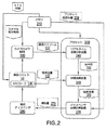
[0057]図2に示すように別の実施形態では、開示されるシステムは、基板とカバーガラスとの間の空間内の流体体積(109)を追跡するためにリアルタイム補給システム(RTRS)を提供し、もしあるなら流体交換システム(280)によって、試料に追加されるまたはそこから除去される流体(279)の量を決定するように構成される。RTRSは、撮像システム(100)、画像分析装置(240)、体積概算装置(260)、ディスペンサ体積計算装置(270)、流体交換システム(280)、およびたとえば染色カセット(50)および流体を転がすカバーガラス、またはARCローラ(130)などの流体動作機構からの位置信号(137)を使用し得る。 [0057] In another embodiment, as shown in FIG. 2, the disclosed system provides a real-time replenishment system (RTRS) to track the fluid volume (109) in the space between the substrate and the cover glass. The fluid exchange system (280), if any, is configured to determine the amount of fluid (279) added to or removed from the sample. The RTRS includes an imaging system (100), an image analyzer (240), a volume estimation device (260), a dispenser volume calculator (270), a fluid exchange system (280), and, for example, a staining cassette (50) and a fluid rolling cover. A position signal (137) from a fluid operating mechanism such as glass or an ARC roller (130) can be used.
[0058]図2でさらに示すように、リアルタイム補給システム(RTRS)は、メモリ(210)、プロセッサ(200)、カメラおよび照明を備える撮像システム(100)、染色カセット(50)、ならびに補給ディスペンサ(280)を備える。撮像システム(100)は、基板の画像情報(127)をプロセッサ(200)内に給送し得る。染色カセット(50)が、測定値を採取する時刻のプロセッサへの信号(137)を送信するとき、プロセッサ(200)は、フィードバック制御ループを形成して、フレームチェックを実行し、ディスペンサ体積計算装置(270)から染色カセット(50)への補給量(279)を提案し得る。一例として、MATLABプログラムは、提案された値を、フィードバック概念を示すようにリアルタイムでユーザインタフェースに出力し得る。別の実施形態では、ディスペンサ体積計算装置(270)からの補給量(279)は、ユーザインタフェースへ提供され得て、ユーザはその後、試薬および/または染料を試料に提供するために流体交換システム(280)を制御することができる。別法として、フィードバック制御ループは、補給量(279)を送達するために、補給ディスペンサ(280)を染色カセット(50)に自動的に向け得る。 As further shown in FIG. 2, the real-time replenishment system (RTRS) includes a memory (210), a processor (200), an imaging system (100) with a camera and lighting, a staining cassette (50), and a replenishment dispenser ( 280). The imaging system (100) may feed the image information (127) of the substrate into the processor (200). When the staining cassette (50) sends a signal (137) to the processor at the time when the measurements are taken, the processor (200) forms a feedback control loop to perform a frame check and dispenser volume calculator. A replenishment amount (279) from (270) to the staining cassette (50) can be proposed. As an example, a MATLAB program may output the proposed value to the user interface in real time to indicate a feedback concept. In another embodiment, the replenishment amount (279) from the dispenser volume calculator (270) can be provided to the user interface and the user can then provide the reagent and / or dye to the sample in a fluid exchange system (279). 280) can be controlled. Alternatively, the feedback control loop may automatically direct the replenishment dispenser (280) to the staining cassette (50) to deliver the replenishment amount (279).
[0059]プロセッサ(200)は、カメラ(125)から取得または撮影された画像を受信するためにカメラに動作可能に接続され得る。プロセッサは、染色カセット(50)内の流体(137)の位置を示すデジタル信号を受信するために、流体動作機構に付随するデジタルI/O装置に動作可能にさらに接続され得る。ある実施形態では、カメラからの画像は、首尾一貫した結果のために、同一の流体位置で撮影され、そして分析され得る。別の実施形態では、画像分析は、カラーまたはグレースケール画像のいずれでも実行され得る。 [0059] The processor (200) may be operably connected to the camera to receive an image acquired or captured from the camera (125). The processor may be further operably connected to a digital I / O device associated with the fluid operating mechanism to receive a digital signal indicating the location of the fluid (137) within the staining cassette (50). In certain embodiments, images from the camera can be taken and analyzed at the same fluid position for consistent results. In another embodiment, the image analysis can be performed on either a color or grayscale image.
[0060]いくつかの実施形態では、メモリ(210)は、プロセッサ(200)に、試料と共に用いられる試薬および/または染料などの流体量を決定するために体積(360)を概算することと、画像(340)を分析することと、どれだけの試薬および/または染料を、概算体積からの情報に基づいて流体交換システムを用いて試料へ適用するかを決定するために補給体積(380)を計算することとを含む、図5に示した動作を実行させる命令を含み得る。命令は、ソフトウェア、ハードウェア、ファームウェア、または任意のその組合せで実施され得る。たとえば、命令は、ソフトウェアで実施され、メモリ内に記憶される。ソフトウェアで実施されるとき、命令は、命令を取り出し、実行する命令実行装置によってまたはそれに関連して使用するための非一時的コンピュータ可読媒体上に、記憶され移送され得る。 [0060] In some embodiments, the memory (210) estimates the volume (360) to the processor (200) to determine the amount of fluid such as reagents and / or dyes used with the sample. The replenishment volume (380) is analyzed to analyze the image (340) and determine how much reagent and / or dye to apply to the sample using the fluid exchange system based on information from the approximate volume. It may include instructions to perform the operation shown in FIG. 5, including calculating. Instructions can be implemented in software, hardware, firmware, or any combination thereof. For example, instructions are executed in software and stored in memory. When implemented in software, instructions may be stored and transferred on a non-transitory computer-readable medium for use by or in connection with an instruction executor that retrieves and executes the instructions.
[0061]一例として、プロセッサは、中央処理装置(CPU)またはデジタルシグナルプロセッサ(DSP)を含み得る。バスなどのローカルインタフェースが、プロセッサと通信し得る。そのうえ、キーパッド、キーボード、またはマウスなどの入力インタフェースが、ユーザからのデータを入力するために使用され得て、プリンタ、モニタ、液晶表示装置(LCD)、または他の表示装置などの出力インタフェースが、ユーザへデータを出力するために使用され得る。また、通信インタフェースが、前部光源、後部光源、カメラ、流体動作機構、および流体交換システムを有する1つまたは複数のネットワークを通じて、データを交換するために使用され得る。 [0061] As an example, the processor may include a central processing unit (CPU) or a digital signal processor (DSP). A local interface, such as a bus, can communicate with the processor. Moreover, an input interface such as a keypad, keyboard, or mouse can be used to enter data from the user, and an output interface such as a printer, monitor, liquid crystal display (LCD), or other display device. , Can be used to output data to the user. Communication interfaces can also be used to exchange data through one or more networks having a front light source, a rear light source, a camera, a fluid operating mechanism, and a fluid exchange system.
[0062]RTRSによって用いられる境界検出方法は、境界検出(341)用の流体(対象)の特徴と異なる特徴を使用し得る。具体的な実施形態では、動作に基づいた前景検出が、透明な流体の境界を検知するために使用され得て、色しきい値検出が、着色された流体の境界を検知するために使用され得る。これらの方法の頑強性により、それらは、組織色変化、任意の組織形態の存在などの多様な条件で機能することが可能になる。 [0062] The boundary detection method used by RTRS may use characteristics different from those of the fluid (object) for boundary detection (341). In a specific embodiment, motion-based foreground detection can be used to detect transparent fluid boundaries, and color threshold detection can be used to detect colored fluid boundaries. obtain. The robustness of these methods allows them to function in a variety of conditions, including tissue color change and the presence of any tissue morphology.
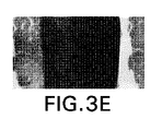
[0063]いくつかの実施形態では、対象の最も明確な特徴が、検出に使用される。たとえば、動作は、それが視野内でスライドガラスに対して移動する唯一の部品であるため、透明な流体の最も明確な特徴である。アルゴリズムは、スライドガラス上の透明な流体の境界を検知するように適合され得る。たとえば、混合ガウス分布モデルの前景検出が、用いられ得る。混合ガウス分布モデルの前景検出算アルゴリズムでは、液滴の左右に配置された2つの流体液滴の境界が、流体体積を計算するために抽出され得る。モデル用パラメータは、実験により選択され、試験は、図3Aおよび3Bによって明白にされたように、信頼できる結果を作成した。図3Aは、透明な流体の撮影画像を示し、図3Bbは、前景検出後のその図3Aの撮影画像を示す。動作に基づいた前景検出方法は、縁どられた透明な流体の識別には好適であるが、この方法を用いたHTXなどの着色された試薬の検出は、図3Eeおよび3Fに示すように、問題があることを証明している。図3Eは、着色された試薬の撮影画像を示し、図3Fは、前景検出後のその図3Eの撮影画像を示す。視野内での移動領域が非常に広いので、プログラムがフレームの背景を識別することは、困難になる。 [0063] In some embodiments, the most distinctive feature of the subject is used for detection. For example, motion is the most obvious feature of clear fluids, as it is the only component that moves relative to the glass slide in the field of view. The algorithm can be adapted to detect transparent fluid boundaries on glass slides. For example, foreground detection of a mixed Gaussian distribution model can be used. In the foreground detection calculation algorithm of the mixed Gaussian distribution model, the boundary between two fluid droplets placed on the left and right of the droplet can be extracted to calculate the fluid volume. Model parameters were selected experimentally and the tests produced reliable results, as demonstrated by FIGS. 3A and 3B. FIG. 3A shows a captured image of the transparent fluid, and FIG. 3Bb shows a captured image of the transparent fluid after the foreground detection. Behavior-based foreground detection methods are suitable for identifying bordered transparent fluids, but detection of colored reagents such as HTX using this method is as shown in FIGS. 3Ee and 3F. Prove that there is a problem. FIG. 3E shows a photographed image of the colored reagent, and FIG. 3F shows a photographed image of the colored reagent after the foreground detection. The area of movement in the field of view is so large that it is difficult for the program to identify the background of the frame.
[0064]染料または着色された試薬の縁部または境界を識別するために、色しきい値検出算アルゴリズムは、流体の明確な色特徴により、着色された試薬用に好適である。組織が、染色処理中に試薬と同様の色に染められるが、試薬の強度は、さらにより強く、それゆえ色しきい値検出方法は、試薬を染料された組織から識別し得る。検出を実行するために、画像は、色相、彩度、および明度(HSV)カラーマップに転送される。適切な色相範囲が試薬の領域を抽出するために選択される。ヘマトキシリンの一例を図3Ccおよび3Dに示す。図3Cは、着色された試薬の撮影画像を示し、図3Dは、前景検出後のその図3Cの撮影画像を示す。色しきい値前景検出アルゴリズムでは、試薬の領域が抽出され得て、流体体積は、抽出された領域から計算され得る。 [0064] To identify the edges or boundaries of dyes or colored reagents, color threshold detection algorithms are suitable for colored reagents due to the distinct color characteristics of the fluid. The tissue is dyed in a color similar to the reagent during the staining process, but the strength of the reagent is even stronger, so the color threshold detection method can identify the reagent from the dyed tissue. To perform the detection, the image is transferred to a hue, saturation, and lightness (HSV) colormap. An appropriate hue range is selected to extract the reagent region. An example of hematoxylin is shown in FIGS. 3Cc and 3D. FIG. 3C shows a photographed image of the colored reagent, and FIG. 3D shows a photographed image of the colored reagent after the foreground detection. In the color threshold foreground detection algorithm, a region of reagent can be extracted and the fluid volume can be calculated from the extracted region.
[0065]カバーガラスおよび基板が互いに対して角度式に動かされる他の実施形態(US7476543、US8454908、およびWO2006116039で開示されたシステムなどの)では、流体本体の一方の境界は、固定位置にあり得て、ただ1つの流体本体の境界が、開示された方法およびシステムで使用する流体幅を決定するために監視される必要があり得る。 [0065] In other embodiments in which the cover glass and substrate are moved angularly with respect to each other (such as the systems disclosed in US 7476543, US 8454908, and WO2006116039), one boundary of the fluid body can be in a fixed position. Thus, the boundaries of only one fluid body may need to be monitored to determine the fluid width used in the disclosed methods and systems.
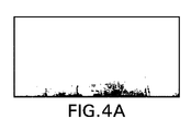
[0066]通常、補給は、体積計算が透明な流体境界を用いた良好な画像を使用して決定されるとき、最も正確である。染色プロセスでは、体積概算の精度に影響を及ぼし、それにより補給量の計算に影響を及ぼし得る問題に遭遇し得る。たとえば、図4Aは、視野を通過し動くピペットアームを有するフレームの前景検出結果の画像である。このフレームは、過大な計算体積をもたらし得て、補給の提案に使用されるべきでない。本問題を克服するために、フレーム内の明画素の比が、フレームチェックの一部として計算され、明画素が、通常予測されるまたは「暗い」画素に対してフレームの約50%以上存在するとき、補給が提案されないことを保証する。すなわち、受け入れ可能なフレームは、通常予測されるまたは「暗い」画素に対して約50%未満の過大な明画素を有する。通常予測されるまたは「暗い」画素が、画像が撮影される際にフレームを通過して動くピペットアームなどの物体からの妨害がないとき、分析中の試料の画素強度に対応し得る画素である。 [0066] Replenishment is usually most accurate when volumetric calculations are determined using good images with transparent fluid boundaries. In the dyeing process, problems can be encountered that affect the accuracy of volume estimation, which in turn can affect the calculation of replenishment. For example, FIG. 4A is an image of the foreground detection result of a frame having a pipette arm moving across the field of view. This frame can result in an excessively calculated volume and should not be used in replenishment proposals. To overcome this problem, the ratio of bright pixels in the frame is calculated as part of the frame check and bright pixels are present at about 50% or more of the frame relative to the normally predicted or "dark" pixels. When guaranteeing that replenishment is not proposed. That is, an acceptable frame has an over-bright pixel that is less than about 50% of the normally expected or "dark" pixels. Usually predicted or "dark" pixels are pixels that can correspond to the pixel intensity of the sample being analyzed when there is no interference from an object such as a pipette arm that moves through the frame when the image is taken. ..
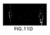
[0067]別の実施形態では、正確な体積計算は、流体境界の一方の部分が視野内にない場合、見出され得ない。図4Bは、流体境界の一部が視野内にない場合の、前景検出の結果画像の一例である。たとえば、流体境界は、大きな体積(200μL以上)がより高速度(100mm/sより大きい)で転がるとき、範囲外に、すなわち視野内にない可能性がある。さらなる実施形態では、前景分析が正しい流体境界をもたらすことができないとき、正確な体積計算は、見出し得ない。これらの場合、RTRSは、先行の体積を現在の体積と比較し得る。2つの体積間に大きな差がある場合、システムは、現在の体積を決定するために後続の測定を用い得る。すなわち、2つの計算体積間に大きな差があるとき、フレームチェック(370)は、体積測定を却下し、新しい画像を取得するプロセスに戻り得る。 In another embodiment, accurate volumetric calculations cannot be found if one part of the fluid boundary is not in the field of view. FIG. 4B is an example of a result image of foreground detection when a part of the fluid boundary is not in the field of view. For example, the fluid boundary may not be out of range, i.e. in the field of view, when a large volume (200 μL or more) rolls at a higher velocity (greater than 100 mm / s). In a further embodiment, accurate volumetric calculations cannot be found when foreground analysis cannot provide the correct fluid boundaries. In these cases, RTRS can compare the preceding volume with the current volume. If there is a large difference between the two volumes, the system may use subsequent measurements to determine the current volume. That is, when there is a large difference between the two calculated volumes, the frame check (370) may reject the volume measurement and return to the process of acquiring a new image.
[0068]図5を参照すると、RTRSプロセスは、画像およびSPSデジタル信号出力を取得するために、カメラおよびデジタル入力/出力(I/O)装置に接続する。画像および信号を用いて、RTRSプログラムは、適切な補給体積を提案するために、画像分析、エラーチェック、および体積計算を実行する。プロセスの開始時点で、カメラおよびI/O装置段取りが開始される(310、320)。露出、明るさ、およびゲインなどのカメラのパラメータが、このステップで設定される。カメラおよびI/O装置が設定された後、プロセスは、カメラからの画像取得(330)のループへと進み、そして取得された画像の分析(340)へと進む。前景検出アルゴリズムは、流体境界を識別するために、画像分析装置によって撮影画像へ適用され得る(341)。ある実施形態では、画像分析装置は、機械学習によって画像背景を識別するために画像または動画と共に継続的に提供され得る。画像分析装置は、処理される画像から任意のノイズを除去し得る(342)。体積計算は、I/O装置が、適切なARC位置、すなわち適切なカバーガラス位置を示す信号を受信するとき、流体測定値を作成するためになされ得る(350)。適切なI/O信号が受信されなかったとき、プロセスは、別の画像を取得することになる。 [0068] With reference to FIG. 5, the RTRS process connects to a camera and a digital input / output (I / O) device to acquire images and SPS digital signal outputs. Using images and signals, the RTRS program performs image analysis, error checking, and volumetric calculations to suggest a suitable replenishment volume. At the start of the process, camera and I / O device setup is initiated (310, 320). Camera parameters such as exposure, brightness, and gain are set in this step. After the camera and I / O device are set up, the process proceeds to a loop of image acquisition from the camera (330) and then to analysis of the acquired image (340). Foreground detection algorithms can be applied to captured images by image analyzers to identify fluid boundaries (341). In certain embodiments, the image analyzer may be continuously provided with an image or moving image to identify the image background by machine learning. The image analyzer can remove any noise from the processed image (342). Volumetric calculations can be made to create fluid measurements when the I / O device receives a signal indicating the appropriate ARC position, i.e. the appropriate cover glass position (350). If the proper I / O signal is not received, the process will acquire another image.
[0069]ある実施形態では、試薬および/または染料の体積は、システム(または「ARC」)図形および測定された流体幅(108)すなわち検出された流体境界間の距離に基づいて、計算され得る(360)。ある実施形態では、計算体積は、体積計算に使用される前提および/または計算精度に影響を及ぼし得る他の可能性のある要素を打ち消すために、較正される必要があり得る。フレームチェック(370)は、次に、フレームおよび対応する体積計算が受け入れ可能であるか否かの判定を実行する。フレームチェックにより、過大な体積変化およびピペットのFOV遮断などの他の異常なフレーム状況を有するフレームを除去することによるエラーチェックを可能にする。フレームチェックが不良フレームを識別する場合、すなわちフレームと関連したエラーまたは異常がある場合、プロセスは、画像取得へと戻る。体積計算が受け入れ可能でない場合、すなわち体積計算と関連したエラーまたは異常がある場合、プロセスは、別の画像取得へと戻る。他の方法では、補給量は、ディスペンサ体積計算装置によって計算され(380)、次のループが、別の画像を取得し始める。 [0069] In certain embodiments, the volume of reagents and / or dyes can be calculated based on the system (or "ARC") shape and the measured fluid width (108) or distance between the detected fluid boundaries. (360). In certain embodiments, the calculated volume may need to be calibrated to counteract the assumptions and / or other potential factors that may affect the calculation accuracy used in the volume calculation. The frame check (370) then performs a determination of whether the frame and the corresponding volume calculation are acceptable. Frame checking allows error checking by removing frames with excessive volume changes and other abnormal frame conditions such as pipette FOV blockage. If the frame check identifies a bad frame, i.e. there is an error or anomaly associated with the frame, the process returns to image acquisition. If the volume calculation is unacceptable, that is, if there are errors or anomalies associated with the volume calculation, the process returns to another image acquisition. In another method, the replenishment amount is calculated by the dispenser volume calculator (380) and the next loop begins to acquire another image.
[0070]いくつかの実施形態では、ARC位置は、測定点を識別するためにフレームごとに取得され得る。ARC位置は、ステップモータ位置によって決定される。図6に示すように、ステップモータ位置は、流体がスライドガラスの縁部付近にあるとき、中心から+4500および−4500付近にある。理想的には、測定値は、ARC位置0が最適の測定点を意味する、スライドガラスの中心で取得されるべきである。しかしながら、いくつかの実施形態では、流体は、動作中ARCの背後に引っ張られており、それゆえ、ARC位置が+4500からの場合、−300付近のARC位置が測定点として採られるべきである。RTRSは、ARC位置を周期的にチェックし得るので、SPSは、ARC位置が−300と+4500との間にある場合は、信号1に、他の位置にある場合は、信号0に調整される。したがって、信号が記録され、先行の信号が1であり、現在の信号が0になる場合、ARC位置が+4500から動いており、体積計算およびフレームチェックを実行するためにRTRSに信号を出す測定点である−300を横切っている。
[0070] In some embodiments, the ARC position can be obtained frame by frame to identify the measurement point. The ARC position is determined by the step motor position. As shown in FIG. 6, the step motor position is near +4500 and -4500 from the center when the fluid is near the edge of the slide glass. Ideally, the measurements should be taken at the center of the glass slide, where
[0071]図6に示すように、カバーガラス位置は、I/O信号によって提供されるように、画像を毎回取得され得て、またはフレームが、基板とカバーガラスとの間の空間内の試薬および/または染料の位置を識別するために取得される。カバーガラス位置は、カバーガラスを動かしそれにより試薬および/または染料を試料上で動かす、流体動作機構内のステップモータ位置によって決定され得る。ある実施形態では、ステップモータ位置および対応するカバーガラス位置は、中心位置から、スライドガラス(図6Bを参照のこと)の右端の試薬および/または染料に対応する一方の端部位置を示す+4500付近、ならびにスライドガラス(図6Aを参照のこと)の左端の試薬および/または染料に対応するもう一方の端部位置を示す−4500付近にあり得る。測定を行うための適切なカバーガラス位置は、試薬および/または染料が、スライドガラスの中心に配置されているときであり得る。図6Cは、試薬および/または染料が、図6Cで右から左へ動くときの中心位置に対応するカバーガラス位置0にある、試薬および/または染料を示し、このとき、カバーガラス位置は、スライドガラスの中心にある試薬および/または染料に対応しない。試薬および/または染料が、カバーガラスと、基板との間の空間内を動くので、適切なカバーガラス位置は、移動する方向ならびに試薬および/または染料の粘性によって決まる、基板の中心(カバーガラス位置0に対応する)に対する所定の場所にあり得る。別の実施形態では、図6dに示すように、試薬および/または染料は、測定点にあり、すなわち、試薬および/または染料は、試薬および/または染料が基板との間の空間内を右から左へ動くとき、スライドガラスの中心、カバーガラス位置−300にある。図6A〜6Dで示した実施形態は、カバーガラス位置に対する試薬および/または染料の位置を示すために使用される概略図であり、構成要素の相対的サイズに関するいかなる詳細も提供することは意図されない。
As shown in FIG. 6, the cover glass position can be imaged each time as provided by the I / O signal, or the frame is a reagent in the space between the substrate and the cover glass. And / or obtained to identify the position of the dye. The cover glass position can be determined by the step motor position within the fluid operating mechanism that moves the cover glass, thereby moving the reagents and / or dyes on the sample. In one embodiment, the step motor position and the corresponding cover glass position are near +4500, indicating the position of one end corresponding to the reagent and / or dye at the right end of the glass slide (see FIG. 6B) from the center position. , And the other end position corresponding to the reagent and / or dye at the left end of the glass slide (see FIG. 6A) may be near -4500. A suitable cover glass position for making measurements may be when the reagent and / or dye is centered on the glass slide. FIG. 6C shows the reagent and / or dye at
[0072]ある実施形態では、RTRSは、カバーガラス位置を周期的にチェックし得る。I/O信号を生成する流体動作機構の検出機構は、カバーガラスが、カバーガラス位置+4500から移動するとき、カバーガラス位置−300を通過するか否かを判定し得る。検出機構は、カバーガラス位置が−300と+4500との間にある場合、I/O信号を「1」に調整し、他の位置では、I/O信号を「0」に調整し得る。RTRSは、I/O信号を記録または記憶し得て、先行のI/O信号が1に等しく、目下のI/O信号が0に変わった場合、このことは、試薬および/または染料が、+4500のカバーガラス位置から移動し、測定に適切な位置にある試薬および/または染料に対応する−300のカバーガラス位置をまさに横切っていることを示し得る。別の実施形態では、検出機構は、カバーガラス位置に対応する信号を送信し得て、RTRSは、検出機構からの信号を評価して、信号からの対応するカバーガラス位置が、カバーガラス位置の所定の場所の所定の範囲内にあるか否かを判断し得る。たとえば、RTRSは、試薬および/または染料が基板との間の空間内を右から左へ動くとき、カバーガラス位置がおよそ−200と−400との間にある場合、正のI/O信号を示し得る。 [0072] In certain embodiments, the RTRS may periodically check the cover glass position. The detection mechanism of the fluid operating mechanism that generates the I / O signal can determine whether or not the cover glass passes through the cover glass position −300 when moving from the cover glass position +4500. The detection mechanism may adjust the I / O signal to "1" if the cover glass position is between -300 and +4500, and adjust the I / O signal to "0" at other positions. If the RTRS can record or store the I / O signal and the preceding I / O signal is equal to 1 and the current I / O signal is changed to 0, this means that the reagents and / or dyes are. It can be moved from the +4500 cover glass position to indicate that it is just across the -300 cover glass position corresponding to the reagent and / or dye in the proper position for measurement. In another embodiment, the detection mechanism may transmit a signal corresponding to the cover glass position, the RTRS evaluates the signal from the detection mechanism, and the corresponding cover glass position from the signal is the cover glass position. It can be determined whether or not it is within a predetermined range of a predetermined place. For example, RTRS gives a positive I / O signal when the reagent and / or dye moves from right to left in the space between the substrate and the cover glass position is between approximately -200 and -400. Can be shown.
[0073]上述のように、試薬および/または染料は、カバーガラス位置の中心の背後に引っ張られている可能性があるので、測定は、基板位置の中心点からわずかに離れて行われるべきである。たとえば、流体動作機構の中心点(138)にある画像を取得するとき、試薬および/または染料が右に動いている場合、試薬および/または染料の大部分は、中心点の左側にあり、試薬および/または染料が左に動いている場合、試薬および/または染料の大部分は、中心点の右側にあり得る。図7に示すように、ARCの中心点(138)が黒線で印をつけられているとき、異なる流体位置が観察され得て、一方、画像はARC動作の中心点で取得される。図7Aおよび7Bでは、流体が右に動くとき背後に引っ張られているので、流体本体は、中心点(138)の左側にあることを見出すことができる。同様に、図7Cおよび7Dに示すように、流体が左へ戻るとき、同一の現象が見出し得る。 [0073] As mentioned above, the measurement should be made slightly away from the center point of the substrate position, as the reagents and / or dyes may be pulled behind the center of the cover glass position. be. For example, when acquiring an image at the center point (138) of the fluid motion mechanism, if the reagent and / or dye is moving to the right, the majority of the reagent and / or dye is to the left of the center point and the reagent. If the and / or dye is moving to the left, most of the reagents and / or dye can be to the right of the center point. As shown in FIG. 7, when the center point (138) of the ARC is marked with a black line, different fluid positions can be observed, while the image is acquired at the center point of the ARC operation. In FIGS. 7A and 7B, the fluid body can be found to be to the left of the center point (138), as it is pulled back as the fluid moves to the right. Similarly, as shown in FIGS. 7C and 7D, the same phenomenon can be found when the fluid returns to the left.
[0074]いくつかの実施形態では、RTRSが一定のカバーガラス位置で画像を取得し得るので、RTRSは、どのように試薬および/または染料が、異なる転がり速度および試薬体積で移動するのか、どのように異なる粘性を有する異なる試薬が、転がる動作中に振る舞うのかを理解するために、試薬および/または染料の動作と、流体動作機構との間の関係を特徴づけるために使用され得る。 [0074] In some embodiments, the RTRS can acquire an image at a constant cover glass position, so the RTRS is how the reagents and / or dyes move at different rolling speeds and reagent volumes. It can be used to characterize the relationship between the operation of reagents and / or dyes and the fluid operation mechanism to understand how different reagents with different viscosities behave during the rolling operation.
[0075]ある実施形態では、RTRSは、画像取得、カバーガラス位置取得、および画像分析を約0.06秒内で実行することができ、およそ毎秒16フレームのフレームレートを有し得る。処理時間は、画像分析を実行するために用いられるプログラミング言語、および画像分析を実行するために用いられるコンピュータの性能に基づき得る。処理時間の改善は、より効果的なプログラミング言語またはより良好に実行するコンピュータを使用することによって、獲得され得る。 [0075] In certain embodiments, the RTRS can perform image acquisition, cover glass position acquisition, and image analysis within about 0.06 seconds and can have a frame rate of approximately 16 frames per second. The processing time can be based on the programming language used to perform the image analysis and the performance of the computer used to perform the image analysis. Improvements in processing time can be gained by using a more effective programming language or a computer that runs better.
[0076]図8の例示的な実施形態に示すように、RTRSのインタフェースは、4つのパネルを備える。上段左側のパネルは、カメラによって取得された目下の画像を示す。上段右側のパネルは、ヘマトキシリンの場合の、混合ガウス分布モデルまたは色しきい値方法を用いて検出された前景を示す。下段左側のパネルは、前景に基づいて計算された目下の体積を示す。測定体積の低下が、観察され得る。たとえば、120秒の転がしの後、8μLの試薬が蒸発した。下段右側のパネルは、ユーザ入力の目標体積、オフセット体積、および測定体積に基づいて示唆される補給を示す。 [0076] As shown in the exemplary embodiment of FIG. 8, the RTRS interface comprises four panels. The upper left panel shows the current image captured by the camera. The upper right panel shows the foreground detected using a mixed Gaussian distribution model or color threshold method for hematoxylin. The lower left panel shows the current volume calculated based on the foreground. A decrease in measured volume can be observed. For example, after 120 seconds of rolling, 8 μL of reagent evaporated. The lower right panel shows the suggested replenishment based on the user-entered target volume, offset volume, and measured volume.
[0077]流体領域での気泡形成は、測定される流体幅を増大させ、RTRSに目下の体積を過大評価させることになる。現象は、カバーガラスと用いられるとき、抗体希釈液などの試薬内で発生し得る。したがって、気泡を除去または補償する方法が必要である。ある実施形態では、流体内部の気泡の円形状が、気泡の存在を検出するために用いられ、次に気泡の補償が実行され得る。円形検出方式は、取得される画像の検出される前景内の任意の気泡を識別するために用いられ得る。例示的な円形検出方式は、画像内の気泡を識別するためにハフ変換に基づき得る。画像内の気泡数を計算し、気泡の体積補償を決定することによって、試薬および/または染料の体積は、試薬および/または染料内の気泡の存在下でより正確に測定されることが可能になる。 Bubble formation in the fluid region increases the measured fluid width and causes the RTRS to overestimate the current volume. The phenomenon can occur in reagents such as antibody diluents when used with cover glass. Therefore, there is a need for a method of removing or compensating for air bubbles. In some embodiments, the circular shape of the bubbles inside the fluid is used to detect the presence of the bubbles, and then compensation for the bubbles can be performed. Circular detection schemes can be used to identify any bubbles in the detected foreground of the acquired image. An exemplary circular detection scheme can be based on the Hough transform to identify bubbles in an image. By calculating the number of bubbles in the image and determining the volume compensation of the bubbles, the volume of the reagent and / or dye can be measured more accurately in the presence of bubbles in the reagent and / or dye. Become.
[0078]図9に示すように、検出される気泡は、円を描く。図9は、さらに示す。気泡がない場合(目下の体積)と、気泡補償がある場合(補償ありの目下の体積)との測定蒸発速度の比較を示す。結果は、1分の転がし操作後にわずか4μLほどの差が見られた。補償なしで、目下の体積は、約151μLから約156μLへの増加として計算され得て、一方気泡補償ありでは、目下の体積は、141μLから134μLへと減少することになると計算される。気泡補償は、図8の目下の体積の同様の傾向に追随し、それは、予測されたように、蒸発により体積損失を示す。 [0078] As shown in FIG. 9, the detected bubbles draw a circle. FIG. 9 further shows. A comparison of the measured evaporation rates between the case without bubbles (current volume) and the case with bubble compensation (current volume with compensation) is shown. As a result, a difference of only about 4 μL was observed after the 1-minute rolling operation. Without compensation, the current volume can be calculated as an increase from about 151 μL to about 156 μL, while with bubble compensation, the current volume is calculated to decrease from 141 μL to 134 μL. Bubble compensation follows a similar trend in volume at present in FIG. 8, which, as expected, exhibits volume loss due to evaporation.
[0079]いくつかの実施形態は、ARC図形およびが測定される流体幅に基づいて体積を概算するために一次近似を提供する体積計算方法を使用する。この手法は、より良好な体積評価のための検量線を必要とする。検量線を導出するために、70から250μLの異なる体積が手動で分配され、転がしプロセスで各体積少なくとも5回ずつテストされた。散布図に既知の分配された体積(209)と、計算体積(109)とをプロットすることによる。検量線が、R2=0.9871を有する検量線図10に示すように見出され得る。さらなる実施形態では、改善された検量線が、検量線のより高い次元を用いて導出され得る。 [0079] Some embodiments use a volumetric method that provides a first-order approximation to estimate the volume based on the ARC figure and the fluid width being measured. This technique requires a calibration curve for better volume assessment. To derive the calibration curve, 70 to 250 μL of different volumes were manually dispensed and tested at least 5 times for each volume in the rolling process. By plotting the known distributed volume (209) and the calculated volume (109) on the scatter plot. A calibration curve can be found as shown in FIG. 10 with a calibration curve having R 2 = 0.9871. In a further embodiment, an improved calibration curve can be derived using the higher dimensions of the calibration curve.
[0080] [0080]
[0081]以下は、振動、ピペットによる視野遮断などのシステム妨害を伴う全負荷状態下で試験されるRTRSの非限定的な実施例である。扁桃腺の試料でのCD−20染色処理が実行され、記録された。結果は、検出システムが流体の領域/縁部を識別できるか否かによって評価された。 [0081] The following are non-limiting examples of RTRSs tested under full load conditions with system disturbances such as vibration, pipette blockage. A CD-20 staining process on tonsil samples was performed and recorded. The results were evaluated by whether the detection system could identify the area / edge of the fluid.
[0082]染色分析での6つの処理が、RTRSを試験するために代表的な事例として列挙された。これらの6つの事例は全て、補給を要するARCシステムを用いて実行された目下の分析プロセスを表す。事例毎に、目標体積が、ピペットによって10回手動で分配され、最初の5データ点が、測定体積とみなされ、事例毎に総数で50のデータポイントとなる。蒸発が5データポイント後に効力を生じ始めるので、最初の5ポイントのみが選択された。事例毎に50データポイントを収集した後、母集団に基づく平均値および標準偏差が、性能を評価するために計算された。未処理のデータが、測定値の分布を示すために四角点を用いてさらに表示されている。 [0082] Six treatments in staining analysis are listed as representative examples for testing RTRS. All six of these cases represent the current analytical process performed using an ARC system that requires replenishment. For each case, the target volume is manually distributed 10 times by a pipette, the first 5 data points are considered as the measured volume, and there are a total of 50 data points for each case. Only the first 5 points were selected, as evaporation begins to take effect after 5 data points. After collecting 50 data points for each case, population-based mean and standard deviation were calculated to assess performance. The raw data is further displayed using square points to show the distribution of the measurements.
[0083]扁桃腺の試料に関する全装填されたCD−20染色プロセスが記録され、前景検出を試験するために使用された。図11に示すように、前景検出がカメラの振動および組織色の変化に耐性を示めすことが見出された。たとえば、図11Bは、組織が色を変化させていく、すなわち図11Aの組織からさらに染色されていくことを示す。明視野撮像内の流体縁部は、流体縁部が組織の背景に溶け込み得るので、組織がより暗い色になるとき観察することが困難であった。この問題は、縁部を明るくするために暗視野撮像を用いることによって解決され、その結果、縁部は、暗い通常の背景に対して強いコントラストを有した。撮像方法を変更することによって、他のARCシステムの陰による干渉および光源を遮断するピペットなどのいくつかの他の問題がさらに解決される。ピペット動作は、視野を遮断するためにさらに観察され、このことは、分析中不回避の処理である。したがって、それが発生することを防止するのではなく、過剰な明画素が、フレームに入り込む大きな物体を多くの場合表すので、視野内に存在するか否かを確認するために、追加の機能がフレームチェックプログラムに追加された。 A fully loaded CD-20 staining process for tonsil samples was recorded and used to test foreground detection. As shown in FIG. 11, it was found that foreground detection was resistant to camera vibration and changes in tissue color. For example, FIG. 11B shows that the tissue changes color, i.e. further stains from the tissue of FIG. 11A. The fluid edges in brightfield imaging were difficult to observe when the tissue became a darker color, as the fluid edges could blend into the tissue background. This problem was solved by using darkfield imaging to brighten the edges, so that the edges had a strong contrast to a dark normal background. Changing the imaging method further solves some other problems such as shadow interference of other ARC systems and pipettes that block the light source. Pipette movements are further observed to block the visual field, which is an unavoidable process during the analysis. Therefore, rather than preventing it from happening, there is an additional feature to see if it is in the field of view, as the excess bright pixels often represent large objects that enter the frame. Added to the frame check program.
[0084]下の表1に示すように、測定体積は、目標体積に標準偏差±1.5%で一致する。このパーセンテージをマイクロリットルに逆変換すると、性能は、±10μLへの変換を果たす。測定体積の分布は、図12で見ることができる。200μL付近の目標体積での分析は、より広いデータの広がりをもたらす。異なる試薬は、異なる粘性を有するので、種々のARC位置範囲が、異なる試薬に使用されるべきであることが分かる。表内の位置範囲は、流体領域を対象領域の中央で撮影する最良の範囲を示す。最終的に、検量線が、計算体積と実際の体積との間の傾きを描写するために導出された。多様な較正定数が、各目標体積の周りの誤差を最小化するために使用された。 [0084] As shown in Table 1 below, the measured volume coincides with the target volume with a standard deviation of ± 1.5%. When this percentage is converted back to microliters, the performance achieves a conversion to ± 10 μL. The distribution of the measured volume can be seen in FIG. Analysis at a target volume near 200 μL results in a wider data spread. Since different reagents have different viscosities, it can be seen that different ARC location ranges should be used for different reagents. The position range in the table indicates the best range in which the fluid region is photographed in the center of the target region. Finally, a calibration curve was derived to depict the slope between the calculated volume and the actual volume. Various calibration constants were used to minimize the error around each target volume.
[0085] [0085]

[0086]前述したように、暗視野撮像により、物体の縁部が検出のために明るくされることが可能になる。図13Aは、照明角度とカメラ位置との間の関係を示し、図13Bは、暗視野撮像内で明るくされた縁部を有する物体を示す。暗視野撮像と明視野撮像とによって取得された透明な流体の写真が、図14で見られる。明視野撮像が、分析用の高品質画像を提供するが(図14Aおよび14B)、流体境界の暗さは、標本が染色されたとき、分析中に課題をもたらす(図14Eおよび14F)。したがって、いくつかの開示された実施形態では、暗視野撮像が、RTRSに利用される(図14Cおよび14D)。 As mentioned above, darkfield imaging allows the edges of an object to be brightened for detection. FIG. 13A shows the relationship between the illumination angle and the camera position, and FIG. 13B shows an object with a brightened edge in darkfield imaging. A photograph of the transparent fluid obtained by darkfield imaging and brightfield imaging can be seen in FIG. While brightfield imaging provides high quality images for analysis (FIGS. 14A and 14B), the darkness of the fluid boundaries poses challenges during analysis when the specimen is stained (FIGS. 14E and 14F). Therefore, in some disclosed embodiments, darkfield imaging is utilized for RTRS (FIGS. 14C and 14D).
[0087] [0087]
[0088]いくつかの一般に用いられる縁部検出器アルゴリズムが利用可能である。これらのアルゴリズムは、Canny、Log、Prewitt、Roberts、Sobel、およびZero Crossを含む。各エッジ検出器は、フレーム内の縁部を識別するためにそれ独自の数学モデルを使用する。図15で示したフレームは、その検出アルゴリズムを使用した縁部検出の例として使用される。 [0088] Several commonly used edge detector algorithms are available. These algorithms include Canny, Log, Prewitt, Roberts, Sobel, and Zero Cross. Each edge detector uses its own mathematical model to identify edges within the frame. The frame shown in FIG. 15 is used as an example of edge detection using the detection algorithm.
[0089]ハフ線検出を使用する縁部検出は、RTRSが異なる組織背景および撮像条件に直面するため、理想的方法とは見られなかった。組織形態は、一旦染色された後、流体縁部検出を悪化させ得る。さらに、異なる縁部検出方法は、異なる感度を有し得る。たとえば、弱い検知方法は、境界の片側を失敗し得て、強い検知方法は、背景内の過剰に多くの不規則な縁部を検知し、流体境界を識別困難にさせ得る。 Edge detection using Huff line detection has not been seen as an ideal method because RTRS faces different tissue backgrounds and imaging conditions. Tissue morphology can exacerbate fluid edge detection once stained. Moreover, different edge detection methods can have different sensitivities. For example, a weak detection method can fail on one side of the boundary, and a strong detection method can detect too many irregular edges in the background, making the fluid boundary difficult to identify.
[0090]多様なアルゴリズムを使用する図15Aの縁部検出を図16に示す。SobelおよびPrewitt検出器は、ヘマトキシリンの縁部をプロットすることができる。しかしながら、染料済み組織の境界も同様に観察可能である。このことは、縁部識別の歩留まりに影響を及ぼす。強い検出器は、Canny、Log、およびZero Crossの事例で示したように、過剰なノイズをプロットし得る。弱い検出器は、流体の縁部を失敗し得る。多様なアルゴリズムを使用する図15Bの縁部検出を図17に示す。SobelおよびPrewitt検出器は、流体縁部を識別することがさらにできる。Robert検出器によって、流体境界の一部が明確でない結果になる。Canny、Log、およびZero Cross検出器によって、組織から過大なノイズ(またはパターン)がもたらされ、それが縁部識別を困難にする。 [0090] The edge detection of FIG. 15A using various algorithms is shown in FIG. Sobel and Prewitt detectors can plot the edges of hematoxylin. However, the boundaries of the dyed tissue are also observable. This affects the yield of edge identification. A strong detector can plot excess noise, as shown in the case of Canny, Log, and Zero Cross. A weak detector can fail the edge of the fluid. Edge detection in FIG. 15B using various algorithms is shown in FIG. Sobel and Prewitt detectors can further identify fluid edges. The Robert detector results in unclear parts of the fluid boundaries. The Canny, Log, and Zero Cross detectors bring excessive noise (or patterns) from the tissue, which makes edge identification difficult.
[0091]染色システムは、RTRSと共存できるようにするために、列パターンを形成しないヒータを有することが好ましい。列パターンを有するヒータは、図18に示すように、性能を妥協し画像処理に影響を及ぼし得る。この問題は、着色された試薬が染料済み組織上に適用されるとき、背景内の列パターンによって生成される強いコントラストによって、より顕著になり得る。 [0091] The staining system preferably has a heater that does not form a row pattern so that it can coexist with RTRS. A heater with a row pattern can compromise performance and affect image processing, as shown in FIG. This problem can be exacerbated by the strong contrast created by the column patterns in the background when the colored reagents are applied on the dyed tissue.
[0092]コンピュータは通常、プロセッサ、オペレーティングシステム、システムメモリ、メモリ記憶装置、入出力制御装置、入出力機構、および表示機器などの周知の構成要素を含む。コンピュータの多くの可能な構成および構成要素が、存在し、キャッシュメモリ、データバックアップ装置、および多くの他の装置をさらに含み得ることを、当業者はさらに理解されたい。入力デバイスの例は、キーボード、カーソル制御装置(たとえば、マウス)、マイクロホン、スキャナ、などを含む。出力装置の例は、表示機器(たとえば、モニタまたはプロジェクタ)、スピーカ、プリンタ、ネットワークカード、などを含む。表示機器は、視覚的な情報を提供する表示機器を含み得て、この情報は通常、論理的かつ/または物理的に画素の配列として構成され得る。入力および出力インタフェースを提供する、種々の既知または将来のソフトウェアプログラムの任意のものを備え得る、インタフェース制御装置もまた含まれ得る。たとえば、インタフェースは、1つまたは複数の図形表現をユーザに提供する、一般に「グラフィカル・ユーザ・インタフェース」と呼ばれる(多くの場合GUIと呼ばれる)ものを含み得る。インタフェースは通常、当業者に知られる選択または入力の手段を使用して、ユーザ入力を受け取ることが可能になる。インタフェースは、タッチ画面であってもよい。同様のまたは代替の実施形態では、コンピュータ上のアプリケーションは、「コマンド・ライン・インタフェース」と呼ばれる(多くの場合CLIと呼ばれる)ものを含み得るインタフェースを利用し得る。CLIは通常、アプリケーションとユーザとの間の文字に基づく相互作用を提供する。通常、コマンド・ライン・インタフェースは、表示機器を介して文字ラインとして、出力を提供し、入力を受信する。たとえば、いくつかの実施態様は、当業者に知られるUnix Shell、またはマイクロソフト社の.NET Frameworkなどのオブジェクト指向型プログラミング・アーキテクチャを利用するマイクロソフト社のWindows Powershellなどの「シェル」と呼ばれるものを含み得る。 [0092] A computer typically includes well-known components such as processors, operating systems, system memory, memory storage devices, input / output controls, input / output mechanisms, and display devices. Those skilled in the art will appreciate that many possible components and components of a computer exist and may further include cache memory, data backup devices, and many other devices. Examples of input devices include keyboards, cursor controls (eg, mice), microphones, scanners, and the like. Examples of output devices include display devices (eg, monitors or projectors), speakers, printers, network cards, and the like. The display device may include a display device that provides visual information, which information can usually be logically and / or physically configured as an array of pixels. Interface controls may also be included, which may include any of a variety of known or future software programs that provide input and output interfaces. For example, an interface may include what is commonly referred to as a "graphical user interface" (often referred to as a GUI) that provides the user with one or more graphic representations. Interfaces will typically be able to receive user input using selection or input means known to those of skill in the art. The interface may be a touch screen. In a similar or alternative embodiment, the application on the computer may utilize an interface that may include what is called a "command line interface" (often called CLI). The CLI typically provides a character-based interaction between the application and the user. Command line interfaces typically provide output and receive input as a character line through a display device. For example, some embodiments may be made from Unix Shell, known to those of skill in the art, or Microsoft. It may include what is called a "shell" such as Microsoft's Windows Powershell, which utilizes an object-oriented programming architecture such as the .NET Framework.
[0093]インタフェースが1つまたは複数のGUI、CLI、またはその組合せを含み得ることを当業者には理解されたい。プロセッサは、インテル社製のCeleron、Core、またはPentiumプロセッサ、サン・マイクロシステムズ社製のSPARCプロセッサ、AMD社製のAthlon、Sempron、Phenom、またはOpteronプロセッサなどの市販されているプロセッサ、あるいは入手可能なまたはこれから入手可能になる他のプロセッサのうちの1つであり得る。プロセッサのいくつかの実施形態は、マルチコアプロセッサというものを含み、かつ/またはシングルまたはマルチコア構成での並列処理技術を利用することが可能にされ得る。たとえば、マルチコア・アーキテクチャは通常、2つ以上のプロセッサ「実行コア」を備える。本実施例では、各実行コアは、マルチスレッドの並列実行を可能にする独立したプロセッサとして実行し得る。さらに、プロセッサは、一般に32または64ビットアーキテクチャと呼ばれるものに構成され得るか、現在知られるもしくは将来開発され得る他のアーキテクチャ構成であり得ることを、当業者は理解されたい。 It will be appreciated by those skilled in the art that an interface may include one or more GUIs, CLIs, or a combination thereof. The processor may be a commercially available processor such as Intel's Celeron, Core, or Pentium processor, Sun Microsystems' SPARC processor, AMD's Athlon, Sempron, Phenom, or Opteron processor, or available. Or it could be one of the other processors that will be available in the future. Some embodiments of the processor may include what is called a multi-core processor and / or make it possible to utilize parallel processing techniques in single or multi-core configurations. For example, a multi-core architecture typically includes more than one processor "execution core". In this embodiment, each execution core can be executed as an independent processor that enables multithreaded parallel execution. Further, those skilled in the art should appreciate that the processor may be configured in what is commonly referred to as a 32-bit or 64-bit architecture, or in other architectural configurations currently known or may be developed in the future.
[0094]プロセッサは通常、オペレーティングシステムを実行するが、それは、たとえばマイクロソフト社のWindows型のオペレーティングシステム、アップルコンピュータ社のMac OS Xオペレーティングシステム、多くの販売店またはオープンソースというものから入手可能なUnixまたはLinux(登録商標)タイプのオペレーティングシステム、別のまたは将来のオペレーティングシステム、あるいはいくつかのその組合せであり得る、オペレーティングシステムは、よく知られている方法でファームウェアおよびハードウェアとインタフェースし、種々のプログラミング言語で記述され得る多様なコンピュータプログラムの機能を調整し実行するプロセッサを支援する。オペレーティングシステムは、通常プロセッサと共同で、コンピュータの他の構成要素の機能を調整し実行する。オペレーティングシステムは、全て周知の技術による、スケジューリング、入出力制御、ファイルおよびデータ管理、メモリ管理、ならびに通信の制御および関連処理をさらに提供する。 [0094] The processor typically runs an operating system, such as Microsoft's Windows-type operating system, Apple Computer's Mac OS X operating system, and Unix available from many retailers or open sources. Or a Linux® type operating system, another or future operating system, or some combination thereof, operating systems interface with firmware and hardware in well-known manners and vary. It assists the operating system in coordinating and executing the functions of various computer programs that can be written in a programming language. The operating system usually works with the processor to coordinate and perform the functions of other components of the computer. The operating system further provides scheduling, input / output control, file and data management, memory management, and communication control and related processing, all with well-known techniques.
[0095]システムメモリは、所望の情報を記憶するために使用し得る、コンピュータによってアクセスされ得る、種々の周知のまたは将来のメモリ記憶装置の任意のものを含み得る。コンピュータ可読記憶媒体は、コンピュータ可読命令、データ構造、プログラムモジュール、または他のデータなどの情報のストレージ用の任意の方法または技術で実装された、揮発性および不揮発性媒体、取り外し可能および取り外し不可能なメディアを含み得る。実施例は、任意の一般に入手可能な、ランダム・アクセス・メモリ(RAM)、読み出し専用メモリ(ROM)、電子的に消去可能なプログラマブル読み出し専用メモリ(EEPROM)、デジタル多用途ディスク(DVD)、内蔵ハードディスクまたはテープなどの磁気媒体、読出しおよび書込みコンパクトディスクなどの光学的媒体、あるいは他のメモリ記憶装置を含む。メモリ記憶装置は、コンパクトディスクドライブ、テープドライブ、取り外し可能なハードディスクドライブ、USBまたはフラッシュドライブ、あるいはフロッピーディスクドライブを含む、種々の周知のまたは将来の装置の任意のものを含み得る。そのようなタイプのメモリ記憶装置は通常、個々に、コンパクトディスク、磁気テープ、取り外し可能なハードディスク、USBまたはフラッシュドライブ、あるいはフロッピーディスクなどのプログラム記憶媒体から読み出し、かつ/またはそれに書き込む。これらのプログラム記憶媒体、または現在使用されている他のものもしくは後に開発されるもののうちの任意のものは、コンピュータプログラム製品と考えられ得る。上記の内容から分かるように、これらのプログラム記憶媒体は通常、コンピュータソフトウェアのプログラムおよび/またはデータを記憶する。コンピュータ制御ロジックとも呼ばれるコンピュータソフトウェアプログラムは通常、システムメモリ内に、および/またはメモリ記憶装置に結合されて使用されるプログラムストレージデバイス内に記憶される。いくつかの実施形態では、コンピュータプログラム製品は、その中に記憶された制御ロジック(プログラムコードを含むコンピュータソフトウェアプログラム)を有するコンピュータ使用可能媒体を備えると説明される。制御ロジックは、プロセッサによって実行されるとき、プロセッサに本明細書で説明した機能を実行させることになる。他の実施形態では、いくつかの機能は、たとえばハードウェア状態機械を使用するハードウェア内に主に実装される。本明細書で説明した機能を実行するハードウェア状態機械の実施態様は、当業者には明らかであろう。入出力制御装置は、人間または機械の、ローカルまたはリモートの、ユーザからの情報を受け入れて処理する任意の種々の周知の装置を含み得る。そのような装置は、たとえばモデムカード、無線カード、ネットワークインタフェースカード、音声カード、または任意の種々の周知の入力装置の他のタイプの制御装置を含む。出力制御装置は、人間または機械の、ローカルまたはリモートの、ユーザへの情報を提供する任意の種々の周知の表示装置の制御装置を含み得る。ここで説明する実施形態では、コンピュータの機能要素は、システムバスを介して互いに通信する。コンピュータのいくつかの実施形態は、ネットワークまたは他のタイプの遠隔通信を用いていくつかの機能要素と通信し得る。当業者には明白であるように、測定器制御および/またはデータ処理アプリケーションは、ソフトウェアで実装されている場合、システムメモリおよび/またはメモリ記憶装置内にロードされ、そこから実行され得る。測定器制御および/またはデータ処理のアプリケーションの全部または部分は、メモリ記憶装置の読み出し専用メモリまたは同様のデバイス内に存在し、そのようなデバイスは、先に測定器制御および/またはデータ処理のアプリケーションが、入出力制御装置を介してロードされていることを必要としない。測定器制御および/またはデータ処理のアプリケーション、またはその一部は、実行に有利なようにシステムメモリまたはキャッシュメモリあるいは両方へ、周知の方法でプロセッサによってロードされ得ることが、当業者には理解されよう。さらに、コンピュータは、システムメモリに記憶された、1つまたは複数のライブラリファイル、試験データファイル、およびインターネットクライアントを含み得る。たとえば、試験データは、検出された信号値、または合成試験またはプロセスによる1つまたは複数の配列決定に関連付けられた他の値などの、1つまたは複数の試験または分析に関するデータを含み得る。さらに、インターネットクライアントは、ネットワークを用いて、別のコンピュータ上のリモートサービスにアクセス可能にされたアプリケーションを含み得て、たとえば一般に「ウェブブラウザ」と呼ばれるものを備え得る。ここでの例では、いくつかの一般に利用されるウェブブラウザは、マイクロソフト社から入手可能なマイクロソフト・インターネット・エクスプローラ、モジラ社のモジラ・ファイアフォックス、アップルコンピュータ社のサファリ、グーグル社のグーグルクローム、または現在当技術分野で知られているもしくは将来開発されることになる他のタイプのウェブブラウザを含む。さらに、同様のまたは他の実施形態では、インターネットクライアントは、生物学のアプリケーション用のデータ処理アプリケーションなどの、ネットワークを介した遠隔情報へのアクセスが可能な特殊用途のソフトウェアアプリケーションを含み得る、またはその構成要素であり得る。 [0095] System memory may include any of a variety of well-known or future memory storage devices that can be used to store desired information and can be accessed by a computer. Computer-readable storage media are volatile and non-volatile media, removable and non-removable, implemented in any way or technique for storing information such as computer-readable instructions, data structures, program modules, or other data. Media can be included. Examples include any generally available random access memory (RAM), read-only memory (ROM), electronically erasable programmable read-only memory (EEPROM), digital versatile disk (DVD), built-in. Includes magnetic media such as hard disks or tapes, optical media such as read and write compact disks, or other memory storage devices. Memory storage devices may include any of a variety of well-known or future devices, including compact disk drives, tape drives, removable hard disk drives, USB or flash drives, or floppy disk drives. Such types of memory storage devices typically read and / or write to, individually, from a program storage medium such as a compact disk, magnetic tape, removable hard disk, USB or flash drive, or floppy disk. Any of these program storage media, or any other currently in use or later developed, can be considered a computer program product. As can be seen from the above, these program storage media typically store computer software programs and / or data. Computer software programs, also called computer control logic, are typically stored in system memory and / or in program storage devices that are used in combination with memory storage devices. In some embodiments, a computer program product is described as comprising a computer-enabled medium having control logic (a computer software program containing program code) stored therein. The control logic, when executed by the processor, causes the processor to perform the functions described herein. In other embodiments, some functionality is implemented primarily within hardware that uses, for example, a hardware state machine. Embodiments of hardware state machines that perform the functions described herein will be apparent to those skilled in the art. The input / output control device may include any of a variety of well-known devices that accept and process information from human or machine, local or remote users. Such devices include, for example, modem cards, wireless cards, network interface cards, voice cards, or other types of control devices for any of a variety of well-known input devices. Output controls may include controls for any of a variety of well-known display devices that provide information to users, local or remote, human or mechanical. In the embodiments described herein, the functional elements of the computer communicate with each other via the system bus. Some embodiments of a computer may communicate with some functional element using a network or other types of telecommunications. As will be apparent to those of skill in the art, instrument control and / or data processing applications, if implemented in software, can be loaded into and executed in system memory and / or memory storage. All or part of the instrument control and / or data processing application resides in the read-only memory of the memory storage device or similar device, such device first in the instrument control and / or data processing application. However, it does not need to be loaded via the I / O controller. It is understood by those skilled in the art that instrument control and / or data processing applications, or parts thereof, can be loaded by a processor in a well-known manner into system memory and / or cache memory in favor of execution. NS. In addition, the computer may include one or more library files, test data files, and internet clients stored in system memory. For example, test data may include data on one or more tests or analyzes, such as detected signal values or other values associated with one or more sequencing by a synthetic test or process. In addition, Internet clients may include applications that have been made accessible to remote services on another computer using a network, such as what is commonly referred to as a "web browser." In the example here, some commonly used web browsers are Microsoft Internet Explorer available from Microsoft, Mozilla Firefox, Apple Computer Safari, Google Chrome, or Includes other types of web browsers currently known in the art or will be developed in the future. Further, in similar or other embodiments, the internet client may include, or special purpose software applications, capable of accessing remote information over a network, such as data processing applications for biology applications. It can be a component.
[0096]ネットワークは、当業者によく知られる多くの多様なタイプのネットワークの1つまたは複数を含み得る。たとえば、ネットワークは、一般にTCP/IPプロトコル・スイートと呼ばれるものを通信に利用し得る、ローカルまたは広域ネットワークを含み得る。ネットワークは、インターネットと一般に呼ばれる、相互接続コンピュータネットワークの世界的システムを備えるネットワークを含み得る、または多様なイントラネットアーキテクチャをさらに含み得る。ネットワーク環境にいるユーザには、ハードウェアおよび/またはソフトウェアシステムへのおよびからの情報トラフィックを制御するために「ファイアウォール」と一般に呼ばれるもの(パケットフィルタまたは境界保護装置と呼ばれる場合もある)を利用することを好み得るユーザもいることが、当業者には理解されよう。たとえば、ファイアウォールは、ハードウェアもしくはソフトウェア構成要素またはいくつかのその組合せを備え得て、たとえばネットワーク管理者などのように、ユーザによって導入されるセキュリティポリシーを強化するように通常設計される。 [0096] The network may include one or more of many diverse types of networks well known to those of skill in the art. For example, the network may include a local or wide area network that may utilize what is commonly referred to as the TCP / IP protocol suite for communication. The network may include a network with a global system of interconnected computer networks, commonly referred to as the Internet, or may further include a variety of intranet architectures. For users in a network environment, use what is commonly referred to as a "firewall" (sometimes called a packet filter or perimeter protector) to control information traffic to and from hardware and / or software systems. Those skilled in the art will understand that some users may like it. For example, a firewall may include hardware or software components or a combination of several thereof, and is typically designed to enhance the security policies implemented by users, such as network administrators.
[0097]本明細書で使用されるとき、用語「約」は、参照数のプラスマイナス10%を示す。
[0098]多様な変形例が当業者には、本明細書で説明したそれらの実施形態に加えて、前述の記述から明らかになるであろう。そのような変形例は、添付の請求項の範囲に含まれることがさらに意図されている。本出願で引用された各参照は、その全体が参照により本明細書に組み込まれる。
[0097] As used herein, the term "about" refers to plus or minus 10% of the number of references.
[0098] Various variations will be apparent to those skilled in the art from the above description, in addition to those embodiments described herein. Such variations are further intended to be included in the appended claims. Each reference cited in this application is incorporated herein by reference in its entirety.
[0099]請求項で引用される参照番号は、例示であり、特許局による審査を容易にするためだけのものであり、何ら限定しない。いくつかの実施形態では、本特許出願書類内で提示された図は、角度、寸法の比、などを含めて、縮尺を合わせて描かれている。いくつかの実施形態では、図は単なる代表物であり、請求項は、図の寸法によって限定されない。いくつかの実施形態では、語句「備える」または「含む」を用いた本明細書での説明は、「から成る」としてさらに説明され得て、そのように、語句「から成る」を用いた1つまたは複数の実施形態を請求するための記述された説明要件は、満足される。 [0099] The reference numbers cited in the claims are examples, are for facilitation of examination by the Patent Office only, and are not limited in any way. In some embodiments, the figures presented within the patent application documents are drawn to scale, including angles, dimensional ratios, and so on. In some embodiments, the figure is merely representative and the claims are not limited by the dimensions of the figure. In some embodiments, the description herein with the phrase "provide" or "contains" can be further described as "consisting of" and thus using the phrase "consisting of" 1 The described explanatory requirements for claiming one or more embodiments are satisfied.
参考文献
[00100]P.Kaewtrakulpong、R.Bowden著「An Improved Adaptive Background Mixture Model for Realtime Tracking with Shadow Detection」、In Proc.2ndEuropean Workshop on Advanced Video Based Surveillance Systems、AVBS01、VIDEO BASE SURVEILLANCE SYSTEMS:Compute Vision and Distributed Processing(2001年9月)。
References
[00100] P.I. Kaewtrakulpong, R.M. Bowden, "An Embedded Adaptive Mixture Model for Realtime Tracking with Shadow Detection", In Proc. 2 nd European Workshop on Advanced Video Based Surveillance Systems, AVBS01, VIDEO BASE SURVEILLANCE SYSTEMS: Compute Vision and Distributed Processing (9 May 2001).
[00101]Stauffer,C.およびGrimson,W.E.L.,、Adaptive Background Mixture Models for Real−Time Tracking, Computer Visions and Pattern Recognition、IEEE Computer Society Conference on、第2巻(1999年8月5日)、2246〜2252ページ、第2巻。 [00101] Staffer, C.I. And Grimson, W. et al. E. L. ,, Adaptive Background Mixture Models for Real-Time Tracking, Computer Visions and Pattern Recognition, IEEE Computer Society Science, pp. 22 (22), 1987, pp.
Claims (16)
a.撮影画像を生成するために撮像システムを用いて、前記生体試料を保持する前記基板(102)上に分配される前記流体の画像を撮影するステップであって、前記流体(105)が前記基板(102)とカバーガラス(130)との間の空間に閉じ込められているステップと、
b.前記基板(102)上に分配され、前記基板(102)と前記カバーガラス(130)との間の前記空間に閉じ込められた前記流体(105)の流体境界(boundaries)(107)を識別するために前記撮影画像を分析するステップと、
c.前記基板(102)上に分配された前記流体(105)の流体体積を前記流体境界から決定される流体幅を用いて計算するステップと、
d.前記計算流体体積および所定の流体体積に基づいて前記流体の前記補給量を計算するステップとを、
含む方法。 A method of estimating the amount of fluid (105) that will be distributed on a substrate (102) that holds a biological sample under analysis.
a. A step of capturing an image of the fluid distributed on the substrate (102) holding the biological sample using an imaging system to generate a captured image, wherein the fluid (105) is the substrate (105). The steps trapped in the space between 102) and the cover glass (130),
b. To identify fluid boundaries (107) of the fluid (105) distributed on the substrate (102) and confined in the space between the substrate (102) and the cover glass (130). And the step of analyzing the captured image
c. A step of calculating the fluid volume of the fluid (105) distributed on the substrate (102) using a fluid width determined from the fluid boundary, and
d. A step of calculating the replenishment amount of the fluid based on the calculated fluid volume and a predetermined fluid volume.
How to include.
前記カメラと、前記カバーガラスの間の距離(128)が、38.1cm(15インチ)から、50.8cm(20インチ)の間である、
請求項1に記載の方法。 The imaging system includes a camera (125) disposed on the cover glass and at least two light sources (110, 120), the first light source (110) being emitted from the first light source (110). The first light (111) is positioned so as to be within the field of view (FOV) of the camera, and the second light source (120) is the second light (121) emitted from the second light source (120). ) Provides an imaging arrangement that is positioned so that it is out of the field of view of the camera (125) and is configured for dark field imaging.
The distance (128) between the camera and the cover glass is between 38.1 cm (15 inches) and 50.8 cm (20 inches).
The method according to claim 1.
前記フレームチェックのエラー反復最大回数が、5回の反復である、
請求項1又は2に記載の方法。 When the frame check is a step of executing a frame check to determine whether or not there is an error or abnormality in the captured image, and the frame check detects an error or abnormality in the captured image, the captured image is said to be said. It further includes the step of repeatedly capturing the image until it passes the frame check or reaches the maximum number of frame check error iterations.
The maximum number of error iterations of the frame check is 5 iterations.
The method according to claim 1 or 2.
請求項1から5のいずれかに記載の方法。 The step of analyzing the captured image comprises applying foreground detection to the captured image to identify the fluid boundary.
The method according to any one of claims 1 to 5.
請求項1から6のいずれかに記載の方法。 The fluid is a transparent fluid and foreground detection based on fluid motion is used to identify the fluid boundary.
The method according to any one of claims 1 to 6.
使用される、
請求項1から7のいずれかに記載の方法。 The fluid is a colored fluid and color threshold detection is used to identify the fluid boundary.
The method according to any one of claims 1 to 7.
請求項1から8のいずれかに記載の方法。 The step of analyzing the captured image further includes the step of removing noise from the background of the captured image.
The method according to any one of claims 1 to 8.
に対する既知の流体体積をプロットすることによって準備され、
前記検量線が、一次の検量線である、
請求項1から9のいずれかに記載の方法。 The step of calculating the fluid volume includes a step of comparing the fluid width with a calibration curve to provide the calculated fluid volume, the calibration curve having a known fluid volume for the corresponding fluid width. Prepared by plotting
The calibration curve is a primary calibration curve,
The method according to any one of claims 1 to 9.
a.前記撮影画像内の気泡を識別するために円形(circle)検出を実行することによって、前記基板と前記カバーガラスとの間の前記空間に閉じ込められた前記分配された流体内の気泡を検出するステップと、
b.気泡の数および各気泡の気泡体積を計算すること、および補正計算体積を提供するために、前記流体幅を使用して決定された前記計算体積から総気泡体積を減じることによって気泡体積を補償するステップと、
c.前記補給量を計算するために、前記補正された計算体積を使用するステップとを、含む、
請求項1から10のいずれかに記載の方法。 The step of calculating the fluid volume is further a. A step of detecting air bubbles in the distributed fluid confined in the space between the substrate and the cover glass by performing a circle detection to identify air bubbles in the captured image. When,
b. Compensate for bubble volume by calculating the number of bubbles and the bubble volume of each bubble, and subtracting the total bubble volume from the calculated volume determined using the fluid width to provide a corrected calculated volume. Steps and
c. Including a step of using the corrected calculated volume to calculate the replenishment amount.
The method according to any one of claims 1 to 10.
及び/又は、
前記フレームチェックを実行するステップが、体積差を得るために、前記計算流体体積を前記所定の流体体積または少なくとも1つの事前に計算された体積と比較するステップを含み、前記体積差と前記所定の流体体積または前記事前に計算された体積との比の絶対値が、前記流体の所定の蒸発速度を使用して計算された差よりも大きいとき、前記画像が、前記フレームチェックを失敗し、
及び/又は、
前記フレームチェックを実行するステップが、フレームチェックエラー反復最大回数に到達した場合にユーザに通知するステップをさらに含む、
請求項3に記載の方法。 When the step of executing the frame check includes a step of calculating the ratio of bright pixels to dark pixels in the captured image, and the ratio of bright pixels to dark pixels in the captured image is larger than 50%, the above. When the image fails the frame check and the ratio of bright pixels to dark pixels in the captured image is less than 50%, the image passes the frame check.
And / or
The step of performing the frame check comprises comparing the calculated fluid volume with the predetermined fluid volume or at least one pre-calculated volume in order to obtain the volume difference, the volume difference and the predetermined. When the absolute value of the fluid volume or its ratio to the pre-calculated volume is greater than the difference calculated using the predetermined evaporation rate of the fluid, the image fails the frame check and fails the frame check.
And / or
The step of executing the frame check further includes a step of notifying the user when the maximum number of frame check error iterations is reached.
The method according to claim 3.
前記可動カバーガラスが、流体を転がすカバーガラス(fluid rolling cover)を含み、前記所定の領域は、前記流体を転がすカバーガラスの位置に対する前記流体位置の動作の遅れを補償するために、前記流体を転がすカバーガラスの中心線からオフセットしており、
更に、前記流体位置を決定するステップが、前記流体を転がすカバーガラスが、前記基板を横断して前記流体を動かそうとするとき、前記流体を転がすカバーガラスの前記中心線に対する前記流体の動作の方向を決定するステップをさらに含む、
請求項4に記載の方法。 The step of determining the fluid position includes a step of determining the position of the movable cover glass, the position of the movable cover glass indicates a relationship with the fluid position, and the position of the movable cover glass is predetermined. When outside the region, the fluid position is outside the predetermined position.
The movable cover glass includes a fluid rolling cover, and the predetermined area covers the fluid in order to compensate for a delay in the operation of the fluid position with respect to the position of the cover glass for rolling the fluid. It is offset from the center line of the rolling cover glass and
Further, in the step of determining the fluid position, when the cover glass that rolls the fluid tries to move the fluid across the substrate, the operation of the fluid with respect to the center line of the cover glass that rolls the fluid. Including additional steps to determine the direction,
The method according to claim 4.
請求項1から13のいずれかに記載の方法。 Further including the step of replenishing the fluid volume by the replenishment amount,
The method according to any one of claims 1 to 13.
a.画像取得記憶システムであって、
i.前記基板および前記カバーガラス上に配置されたカメラ(125)と、
ii.少なくとも2つの光源(110,120)であって、第1の光源(110)が、前記第1の光源(110)から発せられる第1の光(111)が、前記カメラ(125)の視野(FOV)内にあるように位置決めされ、第2の光源(120)が、前記第2の光源(120)から発せられる第2の光(121)が、前記カメラ(125)の前記視野外にあるように位置決めされ、それにより暗視野撮像用に構成された撮像配置を作成する、光源とを含む、
画像取得記憶システムと、
b.前記画像取得記憶システムに動作可能に結合されたプロセッサ(200)と、
c.前記プロセッサ(200)に動作可能に結合されたメモリ(210)であって、デジタルコード化された命令が、前記プロセッサによって実行されるとき、前記プロセッサに、
i.撮影画像を生成するために前記カメラ(125)を用いて、前記生体試料を保持する前記基板(102)上に分配される前記流体(105)の画像を撮影することと、
ii.前記基板(102)上に分配され、前記基板(102)と前記カバーガラス(130)との間の前記空間に閉じ込められた前記流体(105)の流体境界(107)を識別するために前記撮影画像を分析することと、
iii.前記基板(102)上に分配された前記流体(105)の流体体積を前記流体境界から決定される流体幅を用いて計算することと、
iv.前記計算流体体積および所定の流体体積に基づいて前記流体の前記補給量を計算することとを、
含む動作を実行させるように前記システムが構成されるような、前記デジタルコード化された命令を記憶するように構成される、メモリとを、
備える、システム。 A system that estimates the amount of fluid (105) replenished on a substrate (102) containing a biological sample under analysis, wherein the fluid is between the substrate (102) and the cover glass (130). Confined in space, the system
a. Image acquisition storage system
i. A camera (125) arranged on the substrate and the cover glass,
ii. The first light source (110) is at least two light sources (110, 120), and the first light (111) emitted from the first light source (110) is the field of view (FOV) of the camera (125). Positioned so that the second light source (120) is out of the field of view of the camera (125) so that the second light source (120) emitted from the second light source (120) is outside the field of view of the camera (125). Including a light source, which is positioned and thereby creates an imaging arrangement configured for dark field imaging,
Image acquisition storage system and
b. With a processor (200) operably coupled to the image acquisition storage system,
c. A memory (210) operably coupled to the processor (200), the processor, when a digitally coded instruction is executed by the processor.
i. Using the camera (125) to generate a captured image, capturing an image of the fluid (105) distributed on the substrate (102) holding the biological sample, and
ii. The imaging to identify the fluid boundary (107) of the fluid (105) distributed on the substrate (102) and confined in the space between the substrate (102) and the cover glass (130). Analyzing the image and
iii. To calculate the fluid volume of the fluid (105) distributed on the substrate (102) using the fluid width determined from the fluid boundary, and
iv. To calculate the replenishment amount of the fluid based on the computational fluid volume and the predetermined fluid volume.
A memory that is configured to store the digitally coded instructions, such that the system is configured to perform an operation that includes.
Prepare, system.
Applications Claiming Priority (3)
| Application Number | Priority Date | Filing Date | Title |
|---|---|---|---|
| US201662328245P | 2016-04-27 | 2016-04-27 | |
| US62/328,245 | 2016-04-27 | ||
| PCT/EP2017/059769 WO2017186705A1 (en) | 2016-04-27 | 2017-04-25 | System and method for real-time volume control |
Publications (3)
| Publication Number | Publication Date |
|---|---|
| JP2019519757A JP2019519757A (en) | 2019-07-11 |
| JP2019519757A5 JP2019519757A5 (en) | 2020-05-21 |
| JP6908624B2 true JP6908624B2 (en) | 2021-07-28 |
Family
ID=58707487
Family Applications (1)
| Application Number | Title | Priority Date | Filing Date |
|---|---|---|---|
| JP2018554524A Active JP6908624B2 (en) | 2016-04-27 | 2017-04-25 | Systems and methods for real-time volume control |
Country Status (5)
| Country | Link |
|---|---|
| US (1) | US11016006B2 (en) |
| EP (1) | EP3449234B1 (en) |
| JP (1) | JP6908624B2 (en) |
| CN (1) | CN109073517A (en) |
| WO (1) | WO2017186705A1 (en) |
Families Citing this family (5)
| Publication number | Priority date | Publication date | Assignee | Title |
|---|---|---|---|---|
| KR102586862B1 (en) | 2016-10-28 | 2023-10-11 | 베크만 컬터, 인코포레이티드 | Material Readiness Assessment System |
| US11536621B2 (en) | 2020-03-31 | 2022-12-27 | Toyota Research Institute, Inc. | Methods and systems for calibrating deformable sensors using camera |
| DE102020211702A1 (en) | 2020-09-18 | 2022-03-24 | Carl Zeiss Microscopy Gmbh | Method of monitoring an immersion liquid in a microscope |
| KR102597692B1 (en) * | 2020-12-11 | 2023-11-03 | 주식회사 제로클래스랩 | Method, apparatus, and computer program for measuring volume of objects by using image |
| CN115218967B (en) * | 2022-09-21 | 2022-12-13 | 深圳市森盈智能科技有限公司 | Intelligent temperature and moisture control method and intelligent temperature and moisture control device for reagent reaction |
Family Cites Families (35)
| Publication number | Priority date | Publication date | Assignee | Title |
|---|---|---|---|---|
| US5650332A (en) * | 1995-11-14 | 1997-07-22 | Coulter International Corp. | Method for the preparation of microscope slides |
| US6097831A (en) * | 1997-10-14 | 2000-08-01 | Chiron Corporation | Non-contract method for assay reagent volume dispense verification |
| AU1752499A (en) | 1997-12-23 | 1999-07-19 | Dako A/S | Cartridge device for processing a sample mounted on a surface of a support member |
| DE10218988C1 (en) | 2002-04-24 | 2003-11-20 | Horst Dieter Becker | Device and method for wetting objects |
| US7499581B2 (en) * | 2005-02-10 | 2009-03-03 | Forhealth Technologies, Inc. | Vision system to calculate a fluid volume in a container |
| CN101203596A (en) | 2005-04-21 | 2008-06-18 | 塞莱勒斯诊断公司 | Parallel processing fluidic method and apparatus for automated rapid immunohistochemistry |
| AT503573B1 (en) * | 2006-04-13 | 2007-11-15 | Arc Seibersdorf Res Gmbh | DEVICE FOR INCREASING THE RESPONSE, ESPECIALLY THE CONNECTION EFFICIENCY BETWEEN MOLECULES AND MOLECULAR COMPONENTS |
| ES2435535T3 (en) * | 2007-03-02 | 2013-12-20 | Becton, Dickinson And Company | Method and apparatus for automated staining of biological materials |
| AU2008275291B2 (en) | 2007-07-10 | 2012-02-02 | Ventana Medical Systems, Inc. | Apparatus and method for biological sample processing |
| EP2227711A4 (en) * | 2008-01-02 | 2014-01-22 | Univ California | High numerical aperture telemicroscopy apparatus |
| CN102033499A (en) * | 2009-09-28 | 2011-04-27 | 中国科学院空间科学与应用研究中心 | System and method for automatically controlling liquid droplet volume |
| US9498791B2 (en) | 2009-11-13 | 2016-11-22 | Ventana Medical Systems, Inc. | Opposables and automated specimen processing systems with opposables |
| IN2012DN03245A (en) | 2009-11-13 | 2015-10-23 | Ventana Med Syst Inc | |
| JP5703609B2 (en) * | 2010-07-02 | 2015-04-22 | ソニー株式会社 | Microscope and region determination method |
| JP5801410B2 (en) | 2010-11-10 | 2015-10-28 | コンスティテューション・メディカル・インコーポレイテッドConstitution Medical, Inc. | Automated system and method for preparing a biological sample for testing |
| JP5644447B2 (en) * | 2010-12-06 | 2014-12-24 | ソニー株式会社 | Microscope, region determination method, and program |
| US8932543B2 (en) | 2011-09-21 | 2015-01-13 | Sakura Finetek U.S.A., Inc. | Automated staining system and reaction chamber |
| US9734420B2 (en) * | 2011-10-28 | 2017-08-15 | Torsten Matthias | Device and method for inspecting a volume of a sample |
| JP6080860B2 (en) | 2011-11-16 | 2017-02-15 | ライカ・バイオシステムズ・メルボルン・プロプライエタリー・リミテッドLeica Biosystems Melbourne Pty Ltd | Automated system and method for processing tissue samples on slides |
| US20130196339A1 (en) | 2012-01-31 | 2013-08-01 | Thermo Shandon Limited | Slide pocket |
| WO2013127990A1 (en) | 2012-03-01 | 2013-09-06 | Victorious Medical Systems Aps | Method and system for distributing and agitating an amount of liquid over a microscope slide |
| CA2872722C (en) * | 2012-05-11 | 2020-10-06 | Dako Denmark A/S | Method and apparatus for image scoring and analysis |
| ES2808403T3 (en) * | 2012-07-13 | 2021-02-26 | Roche Diagnostics Hematology Inc | Controlled distribution of samples on substrates |
| US10145767B2 (en) | 2012-11-01 | 2018-12-04 | Leica Biosystems Melbourne Pty Ltd | Slide staining assembly and cover member |
| CN104870974B (en) * | 2012-12-26 | 2017-07-18 | 文塔纳医疗系统公司 | Sample processing system and the method for reagent preparation |
| US9989448B2 (en) | 2012-12-26 | 2018-06-05 | Ventana Medical Systems, Inc. | Specimen processing systems and methods for holding slides |
| CN103335993A (en) * | 2013-06-28 | 2013-10-02 | 中国科学技术大学 | Fluorescent dark field microscopy device and method based on waveguide constraint |
| JP2015105998A (en) * | 2013-11-29 | 2015-06-08 | キヤノン株式会社 | Image acquisition device and image acquisition method |
| ES2929493T3 (en) * | 2013-12-13 | 2022-11-29 | Ventana Med Syst Inc | Automated Processing Systems and Microscope Slide Thermal Processing Procedures |
| AU2014363717B2 (en) * | 2013-12-13 | 2016-12-22 | Ventana Medical Systems, Inc. | Automated histological processing of biological specimens and associated technology |
| JP6670503B2 (en) * | 2014-09-24 | 2020-03-25 | 国立大学法人弘前大学 | Method for detecting cancer cells using living cells |
| CN108475328B (en) * | 2015-12-30 | 2022-05-03 | 文塔纳医疗系统公司 | System and method for real-time assay monitoring |
| US10816538B2 (en) * | 2016-01-28 | 2020-10-27 | Siemens Healthcare Diagnostics Inc. | Methods and apparatus for detecting an interferent in a specimen |
| EP3428586B1 (en) * | 2017-07-14 | 2020-09-09 | CSEM Centre Suisse D'electronique Et De Microtechnique SA | Liquid level detection in receptacles using a plenoptic camera |
| JP7276716B2 (en) * | 2017-09-27 | 2023-05-18 | アックスイン ピーティーワイ リミテッド | Diagnostic test system and method |
-
2017
- 2017-04-25 WO PCT/EP2017/059769 patent/WO2017186705A1/en active Application Filing
- 2017-04-25 CN CN201780026077.8A patent/CN109073517A/en active Pending
- 2017-04-25 EP EP17723283.2A patent/EP3449234B1/en active Active
- 2017-04-25 JP JP2018554524A patent/JP6908624B2/en active Active
-
2018
- 2018-10-19 US US16/165,972 patent/US11016006B2/en active Active
Also Published As
| Publication number | Publication date |
|---|---|
| EP3449234B1 (en) | 2020-09-02 |
| EP3449234A1 (en) | 2019-03-06 |
| US20190056295A1 (en) | 2019-02-21 |
| JP2019519757A (en) | 2019-07-11 |
| US11016006B2 (en) | 2021-05-25 |
| WO2017186705A1 (en) | 2017-11-02 |
| CN109073517A (en) | 2018-12-21 |
Similar Documents
| Publication | Publication Date | Title |
|---|---|---|
| JP6908624B2 (en) | Systems and methods for real-time volume control | |
| US11854196B2 (en) | System and method for real time assay monitoring | |
| CN110044405B (en) | Automatic automobile instrument detection device and method based on machine vision | |
| US20030168577A1 (en) | Reverse focusing methods and systems | |
| JP2013526717A (en) | Method and system for identifying well wall boundaries of microplates | |
| US11531032B2 (en) | Methods for measuring analyte and/or protein in biological samples | |
| US20200379232A1 (en) | Optical scanning arrangement and method | |
| US20200018689A1 (en) | Evaluating assays which optical inhomogeneities | |
| BR112019018787B1 (en) | LATERAL FLOW TEST SYSTEM | |
| WO2021134664A1 (en) | Sample analysis system and automatic precision management method therefor | |
| CN112585449A (en) | Method and apparatus for selecting slide medium image reading position | |
| CN114858793A (en) | Sample image photographing system, method, and computer-readable storage medium | |
| CN114858795A (en) | Sample image acquisition system, sample image acquisition method, and readable storage medium | |
| JP2009085694A (en) | Analyzer |
Legal Events
| Date | Code | Title | Description |
|---|---|---|---|
| A521 | Written amendment |
Free format text: JAPANESE INTERMEDIATE CODE: A523 Effective date: 20200413 |
|
| A621 | Written request for application examination |
Free format text: JAPANESE INTERMEDIATE CODE: A621 Effective date: 20200413 |
|
| A977 | Report on retrieval |
Free format text: JAPANESE INTERMEDIATE CODE: A971007 Effective date: 20210324 |
|
| A131 | Notification of reasons for refusal |
Free format text: JAPANESE INTERMEDIATE CODE: A131 Effective date: 20210329 |
|
| A521 | Written amendment |
Free format text: JAPANESE INTERMEDIATE CODE: A523 Effective date: 20210521 |
|
| TRDD | Decision of grant or rejection written | ||
| A01 | Written decision to grant a patent or to grant a registration (utility model) |
Free format text: JAPANESE INTERMEDIATE CODE: A01 Effective date: 20210622 |
|
| A61 | First payment of annual fees (during grant procedure) |
Free format text: JAPANESE INTERMEDIATE CODE: A61 Effective date: 20210701 |
|
| R150 | Certificate of patent or registration of utility model |
Ref document number: 6908624 Country of ref document: JP Free format text: JAPANESE INTERMEDIATE CODE: R150 |