JP6908059B2 - Reclaimer bucket and reclaimer - Google Patents
Reclaimer bucket and reclaimer Download PDFInfo
- Publication number
- JP6908059B2 JP6908059B2 JP2019000954A JP2019000954A JP6908059B2 JP 6908059 B2 JP6908059 B2 JP 6908059B2 JP 2019000954 A JP2019000954 A JP 2019000954A JP 2019000954 A JP2019000954 A JP 2019000954A JP 6908059 B2 JP6908059 B2 JP 6908059B2
- Authority
- JP
- Japan
- Prior art keywords
- bucket
- reclaimer
- wheel
- loose
- water
- Prior art date
- Legal status (The legal status is an assumption and is not a legal conclusion. Google has not performed a legal analysis and makes no representation as to the accuracy of the status listed.)
- Active
Links
Images


Landscapes
- Shovels (AREA)
- Specific Conveyance Elements (AREA)
Description
本発明は、貯蔵ヤードに積み付けられた鉄鉱石や石炭などのバラ物を払い出して次工程に送り出すためのリクレーマーのバケットホイールに取り付けられる掘削用のバケットに関し、及び、前記バケットを備えたリクレーマーに関する。 The present invention relates to a bucket for excavation attached to a bucket wheel of a reclaimer for discharging loose objects such as iron ore and coal loaded in a storage yard and sending them to the next process, and a reclaimer provided with the bucket. Regarding the claimer.
製鉄所などの貯蔵ヤードに積み付けられた鉄鉱石や石炭などのバラ物を掻き取って払い出すリクレーマーとしては、例えば、特許文献1〜3に開示されたリクレーマーがある。これらに開示されたリクレーマーは、図5に、特許文献1に開示されたバケットホイールの概略図を示すように、回転するバケットホイール4を備えている。このバケットホイール4の周方向に沿って取り付けられた、バケットホイール4から張り出した掘削用のバケット1Bが、バケットホイール4の回転によって下側から上側に向かって移動する際に、貯蔵ヤード30に積み付けられた鉄鉱石や石炭などのバラ物20をバケット1Bによって掻き取るように構成されている。
Examples of the reclaimer disclosed in
掘削用のバケット1Bの内部に掻き取られたバラ物20は、バケット1Bがバケットホイール4の上部の予め設定された位置まで移動すると、重力によってバケット1Bから自然落下して、バケット1Bから排出される。バケット1Bから排出されたバラ物20は、バケット1Bの下方に設置されるブームコンベア6の上に落下し、ブームコンベア6によって移送され、更に、ブームコンベア6から地上ベルトコンベア(図示せず)に落下して搬出される。バケット1Bは、バケットホイール4の周方向に沿って複数個設置されている。
When the
尚、図5中の8は電動機、9は電動機8によって回転するスプロケット、10はスプロケット9によって駆動されるチェーンであり、チェーン10がバケットホイール4の外周に設置された歯車(図示せず)と噛み合って、電動機8の動力によってバケットホイール4が回転するように構成されている。
In FIG. 5, 8 is an electric motor, 9 is a sprocket rotated by the
図6に、従来の掘削用のバケット1Bの概略斜視図を示す。バケット1Bは、両側面をバケット側板1a、1aとし、底面をバケット底板1bとし、バケット側板1a及びバケット底板1bの先端部にはバケット刃先1cが取り付けられた、一面を開口部とする箱形形状をしている。バケット刃先1cの先端は開口しており、バラ物20をバケット内に取り込むための取り込み口1dを形成している。
FIG. 6 shows a schematic perspective view of a
このリクレーマーにおいては、貯蔵ヤードに雨水が溜まったときには、バケットが鉄鉱石や石炭などのバラ物を掻き取ると同時に、貯蔵ヤードに溜まった雨水をバケット内に掬い取る。図7に、バラ物を含む水溜まりが発生したときに、従来のバケット1Bでバラ物20を掻き取るときの、バケットホイール4の最下点におけるバケット1Bの側断面概略図を示す。例えば24時間の累積降雨量が60mmを超えるような大雨時には、貯蔵ヤード30にバラ物を含む水溜まり21が発生し、バケットホイール4の最下点に位置するバケット1Bはバラ物を含む水溜まり21の水を掬ってしまう。
In this reclaimer, when rainwater collects in the storage yard, the bucket scrapes loose objects such as iron ore and coal, and at the same time, scoops the rainwater collected in the storage yard into the bucket. FIG. 7 shows a schematic side sectional view of the
大量の水分を含んだバラ物は、流動性が大きいために、地上ベルトコンベアの傾斜部を上がることができず、地上ベルトコンベアの傾斜部の下部にバラ物が滞留する。この傾斜部の下部に滞留したバラ物は地上ベルトコンベアから溢れ出し、バラ物の搬送が不可能になり、製鉄所などの操業に多大な損害を与えることになる。 Since the loose material containing a large amount of water has high fluidity, it cannot go up the inclined portion of the ground belt conveyor, and the loose material stays at the lower part of the inclined portion of the ground belt conveyor. The loose objects that have accumulated in the lower part of the inclined portion overflow from the ground belt conveyor, making it impossible to transport the loose objects, which causes great damage to the operation of the steelworks and the like.
これを防止するために、バケット内への雨水の浸入を防止する対策が行われている。例えば、特許文献4には、バケットホイールを水平面に対して傾斜させたリクレーマーが提案されている。特許文献4によれば、バケットホイールを水平面に対して傾斜させることにより、バケットを水平面(具体的には、地面)に対して傾斜させた状態で移動させることができ、これにより、例えば、降雨時にバケットによって掬い取られる雨水の量を、バケットホイールを水平面に対して傾斜させない場合に比べて、低減させることができるとしている。
In order to prevent this, measures are taken to prevent rainwater from entering the bucket. For example,
また、特許文献5には、バケットの中に、底部と開口部との間を仕切って波形フィルタ板を設けておき、水を含んだ土砂をバケットで掬い取ったとき、前記フィルタ板に振動を与えつつ、バケットの底部空間に溜まった水を排出して、土砂に含まれている水分を減少させる、土砂の水切り方法が提案されている。特許文献5によれば、水分を含有する土砂を波形フィルタ板の上で振動させることで、土砂の粒子と水分とが分離し、土砂の水切りが効率的に行われるとしている。
Further, in
しかしながら、上記従来技術には以下の問題がある。 However, the above-mentioned prior art has the following problems.
即ち、特許文献4の図8には、バケットホイールを傾斜させ、バケットに取り込まれる雨水の量を低減する実施例が示されている。しかしながら、この構造では角部からの雨水の浸入を防ぐことはできない。また、バケットが鉛直方向に対して傾斜しているので、バラ物を搬送するためのバケットの有効内容積が減少し、リクレーマーの能力低下に繋がるおそれがある。
That is, FIG. 8 of
特許文献5の図1に示される構造では、バケットが二重底構造となるので、バケットの有効容積が減少し、リクレーマーの能力低下に繋がる。また、バケットが二重底構造ではないときと同等のバケットの有効容積を確保する場合には、バケットのサイズ拡大が必要になる。更に、フィルタ板や振動装置などの付帯設備による重量増加及びコスト増加が必須であり、特に、バケットホイールの周方向に複数個のバケットを備えたリクレーマーには不利である。
In the structure shown in FIG. 1 of
本発明は上記事情に鑑みてなされたもので、その目的とするところは、バケットホイールに取り付けられた掘削用の複数個のバケットを回転させて鉄鉱石や石炭などのバラ物を掘削し、地上ベルトコンベアに払い出すリクレーマーのバケットにおいて、バケットの有効容積を大きく減らすことなく、貯蔵ヤードにできた水溜まりの水を掬い取ることを抑制することのできる構造のバッケットを提供することであり、また、前記バケットを備えたリクレーマーを提供することである。 The present invention has been made in view of the above circumstances, and an object of the present invention is to rotate a plurality of excavation buckets attached to bucket wheels to excavate loose objects such as iron ore and coal, and to excavate the ground. It is to provide a bucket having a structure capable of suppressing scooping of water in a pool of water formed in a storage yard without significantly reducing the effective volume of the bucket in the bucket of the reclaimer to be discharged to the belt conveyor. , To provide a reclaimer with said bucket.
上記課題を解決するための本発明の要旨は以下のとおりである。
[1]リクレーマーの一部分を構成するバケットホイールの周方向に複数個取り付けられ、貯蔵ヤードに積み付けられた鉄鉱石や石炭などのバラ物を、取り込み口を介して掻き取るバケットであって、
前記バケットの底面の一部に水抜き用開口部が設けられ、
前記取り込み口を起点としてバケットの長さ方向位置を定義したとき、前記水抜き用開口部の設置位置よりも更に前記起点から離れた長さ方向位置のバケットの底面に、長さ方向をバケット幅方向とする堰が設置されていることを特徴とする、リクレーマーのバケット。
[2]前記水抜き用開口部の形状が、円形、楕円形または四角形であることを特徴とする、上記[1]に記載のリクレーマーのバケット。
[3]回転するバケットホイールを具備するリクレーマーであって、
上記[1]または上記[2]に記載のリクレーマーのバケットが、前記バケットホイールの周方向に複数個取り付けられていることを特徴とするリクレーマー。
The gist of the present invention for solving the above problems is as follows.
[1] A bucket that is attached in the circumferential direction of a bucket wheel that constitutes a part of a reclaimer and scrapes loose objects such as iron ore and coal loaded in a storage yard through an intake port.
An opening for draining water is provided in a part of the bottom surface of the bucket.
When the position in the length direction of the bucket is defined with the intake port as the starting point, the width of the bucket is set to the bottom surface of the bucket at a position in the length direction further away from the starting point than the installation position of the drainage opening. A reclaimer bucket characterized by a directional weir.
[2] The bucket of the reclaimer according to the above [1], wherein the shape of the drainage opening is circular, oval, or quadrangular.
[3] A reclaimer provided with a rotating bucket wheel.
A reclaimer according to the above [1] or [2], wherein a plurality of buckets of the reclaimer are attached in the circumferential direction of the bucket wheel.
本発明によれば、リクレーマーの掘削用のバケットの有効容積を大きく減らすことなく、貯蔵ヤードにできた水溜まりの水を掬い取ることを抑制することができ、リクレーマーの設備能力を十分に発揮できるとともに、大雨時にバラ物が大量の水を含むことに起因する操業トラブルを削減することが可能になる。 According to the present invention, it is possible to suppress the scooping of water in the pool of water formed in the storage yard without significantly reducing the effective volume of the excavation bucket of the reclaimer, and the equipment capacity of the reclaimer is fully exhibited. At the same time, it is possible to reduce operational troubles caused by loose objects containing a large amount of water during heavy rain.
以下、添付図面を参照して本発明を具体的に説明する。図1は、本発明の実施の形態の一例を示す図であって、本発明に係る掘削用のバケットを備えた、リクレーマーの一部分を構成するバケットホイールの概略図である。 Hereinafter, the present invention will be specifically described with reference to the accompanying drawings. FIG. 1 is a diagram showing an example of an embodiment of the present invention, and is a schematic view of a bucket wheel constituting a part of a reclaimer provided with a bucket for excavation according to the present invention.
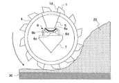
製鉄所などの貯蔵ヤードに積み付けられた鉄鉱石や石炭などのバラ物を掻き取って払い出すリクレーマー(リクレーマーの全体図は図示せず)は、図1に示すように、バラ物20を掻き取るための掘削用のバケット1、及び、周方向に前記バケット1を複数個取り付けたバケットホイール4を備えている。バケットホイール4は、電動機(図示せず)などによって図1に示す矢印の方向(図1に示す反時計回りの方向)に回転し、バケットホイール4から張り出したバケット1が、バケットホイール4の回転に伴って下側から上側に向けて移動する際に、貯蔵ヤード30に積み付けられた鉄鉱石や石炭などのバラ物20をバケット1の取り込み口1dを介して掻き取るように構成されている。
As shown in FIG. 1, the reclaimer that scrapes out loose objects such as iron ore and coal loaded in the storage yard of a steel mill (the overall view of the reclaimer is not shown) is the
バケット1に掻き取られたバケット内のバラ物20は、バケット1がバケットホイール4の上部の予め設定された位置まで移動すると、重力によってバケット1から自然落下し、バケット1から排出される。バケット1から排出されたバラ物20は、シュート5を介してバケット1の下方に設置されるブームコンベア6の上に落下し、ブームコンベア6によってバケットホイール4の回転軸に平行な方向(紙面に垂直の方向)に移送され、更に、ブームコンベア6から地上ベルトコンベア(図示せず)に落下して搬出される。図中、符号の6aは、ブームコンベア6のベルト、6b、6c、6dは、ブームコンベア6のローラ、7は、ブームコンベア6を支持する支持フレームである。
When the
尚、バケットホイール4は前後(紙面の左右)に移動するともに、バケットホイール4の回転軸に平行な方向(紙面に垂直の方向)にも移動し、ブームコンベア6は、バケットホイール4の回転軸に平行な方向(紙面に垂直の方向)への移動範囲を覆うように設置されている。また、シュート5は、バケットホイール4の移動に同期して移動するように構成する、または、ブームコンベア6の上方全面を覆うように設置されており、バケット1から排出されるバラ物20がブームコンベア6の上に確実に落下するように構成されている。
The
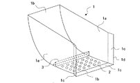
図2に、本発明に係る掘削用のバケット1の概略斜視図を示す。バケット1は、両側面をバケット側板1a、1aとし、底面をバケット底板1bとし、バケット側板1a及びバケット底板1bの先端部にはバケット刃先1cが取り付けられた、一面を開口部とする箱形形状をしている。つまり、バケット刃先1cの先端は開口しており、バラ物20をバケット内に取り込むための取り込み口1dを形成している。
FIG. 2 shows a schematic perspective view of the
バケット底板1bの一部には、バケット底板1bの面に対する形状を円形または楕円形とする複数個の水抜き用開口部2が設けられており、バケット内に水が浸入しても、水抜き用開口部2から水が抜け出す構造になっている。また、取り込み口1dを起点としてバケット1の長さ方向位置を定義したとき、水抜き用開口部2の設置位置よりも更に前記起点から離れた長さ方向位置のバケット底板1bには、長さ方向をバケット幅方向とする堰3が設置されている。堰3を設置することにより、水抜き用開口部2の設置位置を越えてバケット内に水が浸入することが防止できる構造としている。尚、バケット内に水が浸入することをより確実に防止する観点から、堰3を、バケット1の幅全体に渡るように設置することが好ましい。
A part of the
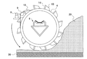
図3に、バラ物20を含む水溜まり21が発生したときに、貯蔵ヤード30に積み付けられたバラ物20をバケット1で掻き取るときの、バケットホイール4の最下点におけるバケット1の側断面概略図を示す。バラ物20とともにバケット内に浸入した水は、水抜き用開口部2を介してバケット1から排出される。また、堰3により、堰3よりもバケット内の奥への水の浸入が防止される。
FIG. 3 shows a side cross section of the
ここで、水抜き用開口部2の開口面積が小さすぎると、十分な水抜き効果が得られず、一方、開口面積が大きすぎると、バラ物20が水抜き用開口部2から流出しやすくなる。したがって、対象とするバラ物20の粒径に応じて前記開口面積を設定する必要がある。例えば、バラ物20の粒径が5〜25mm程度であれば、水抜き用開口部2が円形の場合、水抜き用開口部2の直径を5〜10mm程度とすることが好ましい。水抜き用開口部2の形状が楕円形の場合には、開口面積が円形の場合と同等になるように、楕円形の形状を設定することが好ましい。
Here, if the opening area of the
また、堰3の高さが低すぎると、堰3を越えて水がバケット内に浸入し、一方、堰3の高さが高すぎると、バケット1の有効容積を減らしてしまう。したがって、対象とする貯蔵ヤード30の上面から、バラ物を含む水溜まり21の上面までの高さhに応じて堰3の高さを設定することが好ましい。具体的には、バラ物を含む水溜まり21の高さhよりも堰3の高さが高くなるように、堰3の高さを設定することが好ましい。
Further, if the height of the
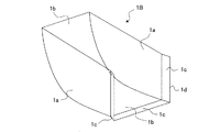
図4は、四角形(長方形)の水抜き用開口部2aが設置された本発明に係る掘削用のバケット1Aを示す概略斜視図である。このバケット1Aでは、四角形の水抜き用開口部2aがバケット1Aの幅方向に格子状に並んで設置されている。四角形の水抜き用開口部2aを格子状に並べて設置することで、円形及び楕円形の水抜き用開口部2に比べて、より高い水切り効果を得ることができる。
FIG. 4 is a schematic perspective view showing a
但し、四角形の水抜き用開口部2aを格子状に並べて設置した場合には、円形及び楕円形の水抜き用開口部2に比べて、開口面積が大きくなるので、粘着性の高いバラ物や粒径の大きいバラ物を対象とすることが好ましい。ここで、四角形(長方形)の水抜き用開口部2aの開口幅、及び、隣り合う水抜き用開口部2aの間隔は、バラ物20の粒径に応じて設定する必要があり、バラ物20の粒径が50〜150mm程度であれば、水抜き用開口部2aの開口幅、及び、隣り合う水抜き用開口部2aの間隔を50mm程度とすることが好ましい。
However, when the
以上説明したように、本発明によれば、リクレーマーの掘削用のバケットの有効容積を大きく減らすことなく、貯蔵ヤードにできた水溜まりの水を掬い取ることを抑制することができ、リクレーマーの設備能力を十分に発揮できるとともに、大雨時にバラ物が大量の水を含むことに起因する操業トラブルを削減することが可能になる。 As described above, according to the present invention, it is possible to suppress the scooping of water in the puddle formed in the storage yard without significantly reducing the effective volume of the excavation bucket of the reclaimer. It is possible to fully demonstrate the equipment capacity and reduce operational troubles caused by loose objects containing a large amount of water during heavy rain.
尚、本発明は上記説明の範囲に限定されるものではなく、種々の変更が可能である。例えば上記説明では、ブームコンベア6の移動方向がバケットホイール4の回転軸に平行な方向であるが、ブームコンベアの移動方向がバケットホイール4の回転方向と平行な方向であるリクレーマーであっても本発明は適用可能である。
The present invention is not limited to the scope of the above description, and various modifications can be made. For example, in the above description, the moving direction of the boom conveyor 6 is parallel to the rotation axis of the
要は、回転し、周方向に沿って複数個の掘削用のバケットが設置されたバケットホイール4を具備するリクレーマーである限り、本発明を適用可能である。
In short, the present invention can be applied as long as the reclaimer includes a
1 バケット
1A バケット
1B 従来のバケット
1a バケット側板
1b バケット底板
1c バケット刃先
1d 取り込み口
2 水抜き用開口部
2a 水抜き用開口部
3 堰
4 バケットホイール
5 シュート
6 ブームコンベア
7 支持フレーム
8 電動機
9 スプロケット
10 チェーン
20 バラ物
21 バラ物を含む水溜まり
30 貯蔵ヤード
1
Claims (3)
前記バケットの底面の一部に水抜き用開口部が設けられ、
前記取り込み口を起点としてバケットの長さ方向位置を定義したとき、前記水抜き用開口部の設置位置よりも更に前記起点から離れた長さ方向位置のバケットの底面に、長さ方向をバケット幅方向とする堰が設置されていることを特徴とする、リクレーマーのバケット。 A bucket that is attached in the circumferential direction of the bucket wheels that form part of the reclaimer and scrapes loose objects such as iron ore and coal loaded in the storage yard through the intake port.
An opening for draining water is provided in a part of the bottom surface of the bucket.
When the position in the length direction of the bucket is defined with the intake port as the starting point, the width of the bucket is set to the bottom surface of the bucket at a position in the length direction further away from the starting point than the installation position of the drainage opening. A reclaimer bucket characterized by a directional weir.
請求項1または請求項2に記載のリクレーマーのバケットが、前記バケットホイールの周方向に複数個取り付けられていることを特徴とするリクレーマー。 A reclaimer with a rotating bucket wheel
A reclaimer according to claim 1 or 2, wherein a plurality of buckets of the reclaimer are attached in the circumferential direction of the bucket wheel.
Priority Applications (1)
| Application Number | Priority Date | Filing Date | Title |
|---|---|---|---|
| JP2019000954A JP6908059B2 (en) | 2019-01-08 | 2019-01-08 | Reclaimer bucket and reclaimer |
Applications Claiming Priority (1)
| Application Number | Priority Date | Filing Date | Title |
|---|---|---|---|
| JP2019000954A JP6908059B2 (en) | 2019-01-08 | 2019-01-08 | Reclaimer bucket and reclaimer |
Publications (2)
| Publication Number | Publication Date |
|---|---|
| JP2020111393A JP2020111393A (en) | 2020-07-27 |
| JP6908059B2 true JP6908059B2 (en) | 2021-07-21 |
Family
ID=71666311
Family Applications (1)
| Application Number | Title | Priority Date | Filing Date |
|---|---|---|---|
| JP2019000954A Active JP6908059B2 (en) | 2019-01-08 | 2019-01-08 | Reclaimer bucket and reclaimer |
Country Status (1)
| Country | Link |
|---|---|
| JP (1) | JP6908059B2 (en) |
Families Citing this family (1)
| Publication number | Priority date | Publication date | Assignee | Title |
|---|---|---|---|---|
| JP7718442B2 (en) * | 2023-03-13 | 2025-08-05 | Jfeスチール株式会社 | Reclaimer bucket and reclaimer |
Family Cites Families (4)
| Publication number | Priority date | Publication date | Assignee | Title |
|---|---|---|---|---|
| JPS5761173Y2 (en) * | 1979-07-05 | 1982-12-27 | ||
| JPS6014155U (en) * | 1983-07-11 | 1985-01-30 | 羽切 吉一 | Shovel drainage device |
| JP3964831B2 (en) * | 2003-06-27 | 2007-08-22 | 正巳 川名 | Bucket for hydraulic excavator |
| JP5640384B2 (en) * | 2010-01-15 | 2014-12-17 | 新日鐵住金株式会社 | Reclaimer |
-
2019
- 2019-01-08 JP JP2019000954A patent/JP6908059B2/en active Active
Also Published As
| Publication number | Publication date |
|---|---|
| JP2020111393A (en) | 2020-07-27 |
Similar Documents
| Publication | Publication Date | Title |
|---|---|---|
| US20250214791A1 (en) | Offloading vacuum tank | |
| KR102459781B1 (en) | Rotary screen with hopper type rake for removal of underwater debris | |
| JP6908059B2 (en) | Reclaimer bucket and reclaimer | |
| JP6055972B2 (en) | Surface soil stripping collection vehicle and bucket | |
| US20090000916A1 (en) | Aggregate Reclaimer Device and Method | |
| CN105775783A (en) | Coal storage system of coal-fired power plant | |
| RU2125910C1 (en) | Self-unloading sluice | |
| CN113089676A (en) | Rapid unearthing system for ultra-deep foundation pit | |
| JP5490629B2 (en) | Garbage truck | |
| KR102715752B1 (en) | Rail cleaning device for continuous ship unloader | |
| US1946663A (en) | Dewatering device | |
| KR101038688B1 (en) | Wrinkled Belt Conveyor | |
| TWI527749B (en) | Continuous unloader | |
| CN203603184U (en) | Scraper pan | |
| JP2004044264A (en) | Dust screen | |
| CN219450862U (en) | Mining excavator bucket | |
| JP2025023386A (en) | Reclaimer bucket and reclaimer | |
| CN210682335U (en) | Prevent piling up transport mechanism with transition device | |
| JPS6119501B2 (en) | ||
| CN114293611B (en) | Drainage canal silt treatment equipment for hydraulic engineering | |
| CN116181960A (en) | Integrated pipeline laying device | |
| JP5099813B2 (en) | Material recovery equipment used in the reticulated air chamber type wet specific gravity sorter | |
| CN210676905U (en) | Sand feeding base for sand core removing device of casting | |
| KR200244707Y1 (en) | rotary type dust removing machine | |
| JP6953491B2 (en) | Dust remover and its installation method |
Legal Events
| Date | Code | Title | Description |
|---|---|---|---|
| RD04 | Notification of resignation of power of attorney |
Free format text: JAPANESE INTERMEDIATE CODE: A7424 Effective date: 20190327 |
|
| A621 | Written request for application examination |
Free format text: JAPANESE INTERMEDIATE CODE: A621 Effective date: 20200824 |
|
| TRDD | Decision of grant or rejection written | ||
| A977 | Report on retrieval |
Free format text: JAPANESE INTERMEDIATE CODE: A971007 Effective date: 20210527 |
|
| A01 | Written decision to grant a patent or to grant a registration (utility model) |
Free format text: JAPANESE INTERMEDIATE CODE: A01 Effective date: 20210601 |
|
| A61 | First payment of annual fees (during grant procedure) |
Free format text: JAPANESE INTERMEDIATE CODE: A61 Effective date: 20210614 |
|
| R150 | Certificate of patent or registration of utility model |
Ref document number: 6908059 Country of ref document: JP Free format text: JAPANESE INTERMEDIATE CODE: R150 |
|
| R250 | Receipt of annual fees |
Free format text: JAPANESE INTERMEDIATE CODE: R250 |
|
| R250 | Receipt of annual fees |
Free format text: JAPANESE INTERMEDIATE CODE: R250 |