JP6907313B2 - Downlink control channel mapping according to numerology - Google Patents
Downlink control channel mapping according to numerology Download PDFInfo
- Publication number
- JP6907313B2 JP6907313B2 JP2019525842A JP2019525842A JP6907313B2 JP 6907313 B2 JP6907313 B2 JP 6907313B2 JP 2019525842 A JP2019525842 A JP 2019525842A JP 2019525842 A JP2019525842 A JP 2019525842A JP 6907313 B2 JP6907313 B2 JP 6907313B2
- Authority
- JP
- Japan
- Prior art keywords
- numerology
- symbol
- mapping
- channel
- computer program
- Prior art date
- Legal status (The legal status is an assumption and is not a legal conclusion. Google has not performed a legal analysis and makes no representation as to the accuracy of the status listed.)
- Active
Links
Images


Classifications
-
- H—ELECTRICITY
- H04—ELECTRIC COMMUNICATION TECHNIQUE
- H04L—TRANSMISSION OF DIGITAL INFORMATION, e.g. TELEGRAPHIC COMMUNICATION
- H04L5/00—Arrangements affording multiple use of the transmission path
- H04L5/0001—Arrangements for dividing the transmission path
- H04L5/0014—Three-dimensional division
- H04L5/0023—Time-frequency-space
-
- H—ELECTRICITY
- H04—ELECTRIC COMMUNICATION TECHNIQUE
- H04L—TRANSMISSION OF DIGITAL INFORMATION, e.g. TELEGRAPHIC COMMUNICATION
- H04L5/00—Arrangements affording multiple use of the transmission path
- H04L5/003—Arrangements for allocating sub-channels of the transmission path
- H04L5/0053—Allocation of signaling, i.e. of overhead other than pilot signals
-
- H—ELECTRICITY
- H04—ELECTRIC COMMUNICATION TECHNIQUE
- H04L—TRANSMISSION OF DIGITAL INFORMATION, e.g. TELEGRAPHIC COMMUNICATION
- H04L27/00—Modulated-carrier systems
- H04L27/26—Systems using multi-frequency codes
- H04L27/2601—Multicarrier modulation systems
- H04L27/2602—Signal structure
-
- H—ELECTRICITY
- H04—ELECTRIC COMMUNICATION TECHNIQUE
- H04L—TRANSMISSION OF DIGITAL INFORMATION, e.g. TELEGRAPHIC COMMUNICATION
- H04L27/00—Modulated-carrier systems
- H04L27/26—Systems using multi-frequency codes
- H04L27/2601—Multicarrier modulation systems
- H04L27/2602—Signal structure
- H04L27/26025—Numerology, i.e. varying one or more of symbol duration, subcarrier spacing, Fourier transform size, sampling rate or down-clocking
-
- H—ELECTRICITY
- H04—ELECTRIC COMMUNICATION TECHNIQUE
- H04L—TRANSMISSION OF DIGITAL INFORMATION, e.g. TELEGRAPHIC COMMUNICATION
- H04L5/00—Arrangements affording multiple use of the transmission path
- H04L5/003—Arrangements for allocating sub-channels of the transmission path
- H04L5/0058—Allocation criteria
- H04L5/0064—Rate requirement of the data, e.g. scalable bandwidth, data priority
-
- H—ELECTRICITY
- H04—ELECTRIC COMMUNICATION TECHNIQUE
- H04L—TRANSMISSION OF DIGITAL INFORMATION, e.g. TELEGRAPHIC COMMUNICATION
- H04L5/00—Arrangements affording multiple use of the transmission path
- H04L5/0091—Signaling for the administration of the divided path
- H04L5/0092—Indication of how the channel is divided
Description
本明細書において開示されているのは、ネットワークにおいて複数のヌメロロジー(numerology)を有効化するための方法、ならびに、ネットワークのユーザ機器、基地局、コンピュータプログラムおよびコンピュータプログラムデバイスである。 Disclosed herein are methods for enabling multiple numerologies in a network, as well as network user equipment, base stations, computer programs and computer program devices.
第5世代の移動体通信およびワイヤレス技術はまだ完全には定義されていないが、第3世代パートナーシッププロジェクト(3GPP)内では進歩した起草段階にある。これは、5G New Radio(NR)アクセス技術に関する研究を含む。5Gにおいては異なる用語が指定されるが、本開示においては、均等な5Gエンティティまたは機能を含めるために、ロングタームエボリューション(LTE)の専門用語が、将来を見通す意味合いで使用される。2016年11月現在の5G NRアクセス技術に関する合意の全般的な記述は、3GPP Technical Report 38.802 v0.3.0(2016−11)に包含 されている。 Fifth generation mobile communications and wireless technologies are not yet fully defined, but are in the advanced drafting stage within the Third Generation Partnership Project (3GPP). This includes research on 5G New Radio (NR) access technology. Although different terms are specified in 5G, in this disclosure the terminology of Long Term Evolution (LTE) is used in a forward-looking sense to include equal 5G entities or features. A general description of the agreement on 5G NR access technology as of November 2016 is contained in 3GPP Technical Report 38.802 v0.3.0 (2016-11).
3GPPにおいては、5Gのための新規の無線インターフェースを検討する過去のおよび進行中の研究項目が存在する。この新規の次世代技術を表すための用語はまだ1つに定まっておらず、そのため、NRおよび5Gという用語は交換可能に使用される。 In 3GPP, there are past and ongoing research items examining new wireless interfaces for 5G. The terms NR and 5G are used interchangeably because the terms used to describe this new next-generation technology have not yet been settled.
3GPP TSG RAN WG1がNR関連事項について行う必要がある第1の主要な決定の1つが、「ヌメロロジー」および「フレーム構造」という用語によって表されることが多いものである。3GPP TSG RAN WG1において、ヌメロロジーという用語は、サブキャリア間隔(SCS)、OFDMシンボル長、サイクリックプレフィックス長、サブフレームまたはスロットあたりのシンボルの数、サブフレーム長、およびフレーム長などのOFDM無線インターフェースの態様を記述する重要な数値パラメータを決定するために使用される。これらの用語のいくつかはまた、例えば、フレーム長、フレームあたりのサブフレームの数、サブフレーム長、ならびに、制御情報を搬送するスロット、フレームまたはサブフレーム内のシンボルの位置および数、ならびに、データを搬送するチャネルの位置などのフレーム構造という用語の分類にも入る場合がある。NRにおいて、サブフレームは1msであり、1msクロックを確立する。送信にはスロットまたはミニスロットが使用される。スロットは7または14のシンボルから成り、7シンボルは、60kHz以下のサブキャリア間隔のためのものであり、14シンボルは60kHzよりも大きいサブキャリア間隔のためのものである。 One of the first major decisions that the 3GPP TSG RAN WG1 needs to make on NR-related matters is often expressed by the terms "numerology" and "frame structure". In 3GPP TSG RAN WG1, the term numerology refers to OFDM radio interfaces such as subcarrier spacing (SCS), OFDM symbol length, cyclic prefix length, number of symbols per subframe or slot, subframe length, and frame length. Used to determine important numerical parameters that describe aspects. Some of these terms also include, for example, frame length, number of subframes per frame, subframe length, and the position and number of slots, frames or symbols within subframes that carry control information, and data. It may also fall into the category of terms such as frame structure, such as the position of the channel that carries the. In NR, the subframe is 1 ms, establishing a 1 ms clock. Slots or minislots are used for transmission. Slots consist of 7 or 14 symbols, 7 symbols for subcarrier spacing below 60 kHz and 14 symbols for subcarrier spacing greater than 60 kHz.
加えて、フレーム構造という用語は、例えば、参照信号(パイロット信号)の定位および密度、制御チャネルの配置および構造、時分割複信(TDD)のための上りリンクから下りリンクへの(およびその逆の)切り替えのためのガード時間の位置および長さ、ならびに時間位置整合など、フレーム、サブフレームおよびスロットの構造を反映する様々な追加の態様を含み得る。一般的に、ヌメロロジーおよびフレーム構造は、無線インターフェースの基本的な態様およびパラメータのセットを包含する。 In addition, the term frame structure refers to, for example, localization and density of reference signals (pilot signals), control channel arrangement and structure, uplink to downlink (and vice versa) for Time Division Duplex (TDD). It may include various additional aspects that reflect the structure of frames, subframes and slots, such as the position and length of guard time for switching, as well as time alignment. In general, numerology and frame structure include a set of basic aspects and parameters of a radio interface.
LTEは、15kHzの単一のサブキャリア間隔をサポートする。LTEにおけるいくつかの他のパラメータについては、いくらかの追加の自由度が存在する。例えば、サイクリックプレフィックスの長さおよびサブフレーム内の制御領域のサイズを設定することが可能である。同様に、LTEは、例えば、それぞれ周波数分割複信(FDD)、TDD、および狭帯域モノのインターネット(NB−IoT)のための複数の異なるフレーム構造をサポートすることができる。 LTE supports a single subcarrier spacing of 15 kHz. There are some additional degrees of freedom for some other parameters in LTE. For example, it is possible to set the length of the cyclic prefix and the size of the control area within the subframe. Similarly, LTE can support multiple different frame structures, for example, for Frequency Division Duplex (FDD), TDD, and the Internet of Things (NB-IoT), respectively.
3GPP TSG RAN WG1は最近、NRにおいて、混合したサブキャリア間隔を同じキャリア上でサポートすることが可能であるべきであると合意した。混合サブキャリア間隔の実現可能性は、例えば、3GPP contribution R1−163224において研究されており、非直交サブキャリア間の干渉を首尾よく軽減することができることが示されている。 3GPP TSG RAN WG1 recently agreed that in NR it should be possible to support mixed subcarrier spacing on the same carrier. The feasibility of mixed subcarrier spacing has been studied, for example, in 3GPP contribution R1-163224, and it has been shown that interference between non-orthogonal subcarriers can be successfully mitigated.
下りリンク制御チャネル
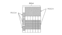
NRについて、提案されているフレーム構造およびDL制御チャネル構造が、図3に示されている。第1のOFDMシンボルは、少なくとも物理下りリンク制御チャネル(PDCCH)を包含する。PDCCHを搬送するOFDMシンボルのセットは、制御領域として知られている。制御領域の長さは、固定であり得るか、半静的に設定され得るか、または、動的にシグナリングされ得る。制御領域を有するOFDMシンボルに後続して、データおよび復調用参照信号(DMRS)が開始する。
The proposed frame structure and DL control channel structure for the downlink control channel NR are shown in FIG. The first OFDM symbol includes at least a physical downlink control channel (PDCCH). The set of OFDM symbols that carry the PDCCH is known as the control region. The length of the control area can be fixed, semi-statically set, or dynamically signaled. An OFDM symbol with a control area is followed by a data and demodulation reference signal (DMRS).
1人の特定のユーザに対するPDCCHが、OFDMサブキャリアのサブセット上で搬送される。PDCCHのマッピングは、分散されるかまたは局在化されるかのいずれかであり得る。局在化マッピングにおいて、制御チャネルエレメント(CCE)が、同じ物理リソースブロック(PRB)対内のリソースエレメント(RE)によって形成される。分散マッピングにおいてCCEは、2つ以上のPRB対内のREによって形成される。単純にするために、図3内の図解は局在化されている。 PDCCH for one particular user is carried on a subset of OFDM subcarriers. The PDCCH mapping can be either distributed or localized. In localization mapping, a control channel element (CCE) is formed by resource elements (RE) within the same physical resource block (PRB) pair. In distributed mapping, CCE is formed by RE within two or more PRB pairs. For simplicity, the illustrations in FIG. 3 are localized.
PDCCHは、とりわけ、同じスロット(または後のスロットも)内のDLリソースを指示する下りリンクスケジューリング情報を搬送することができる。図3は、上方ハッシングおよび水平ハッシングに対応する、2つのPDCCHおよび対応する2つのスケジューリングされている物理下りリンク共有チャネル(PDSCH)を示す。加えて、下方ハッシングに対応する、例えばUL grantなど、対応するPDSCHを有しない第3のPDCCHが示されている。UEは、当該UEにアドレス指定されているPDCCHを検出し、当該PDCCHから、スケジューリング情報など、関連する制御情報を導出する。図面は、1つのOFDMシンボルの制御領域サイズの事例を図解している。制御領域が複数のOFDMシンボルにわたって延在する場合、PDCCHのマッピングは、1つのPDCCHが単一のOFDMシンボルに制約されず、制御領域内の複数のOFDMシンボルにまたがることが許容されるように行われ得る(マルチシンボルPDCCHマッピング)。代替的に、マッピングは、1つのPDCCHが1つのOFDMシンボル内でのみ送信される(複数のPDCCHは1つのOFDMシンボル内で送信され得る(シンボル毎のマッピング))ようなものであってもよい。標準的には、1つのPDCCHは、特定の無線ネットワーク一時識別子(RNTI)と関連付けられる。RNTIは特定のUE、UEのグループまたはセルのすべてのUEと関連付けられ得るため、1つのPDCCHは、1つのUE、セル内のすべてのUE、または、セル内のUEのサブグループに対して方向付けられ得る。 The PDCCH can, among other things, carry downlink scheduling information pointing to DL resources within the same slot (or later slots). FIG. 3 shows two PDCCHs and two corresponding scheduled physical downlink shared channels (PDSCHs) corresponding to upward hashing and horizontal hashing. In addition, a third PDCCH that does not have a corresponding PDSCH, such as UL grant, corresponding to downward hashing is shown. The UE detects the PDCCH addressed to the UE and derives related control information such as scheduling information from the PDCCH. The drawing illustrates an example of the control area size of one OFDM symbol. If the control area extends over multiple OFDM symbols, the PDCCH mapping is such that one PDCCH is not constrained to a single OFDM symbol and is allowed to span multiple OFDM symbols within the control area. Can be (multi-symbol PDCCH mapping). Alternatively, the mapping may be such that one PDCCH is transmitted only within one OFDM symbol (multiple PDCCHs can be transmitted within one OFDM symbol (symbol-by-symbol mapping)). .. Standardly, one PDCCH is associated with a particular radio network temporary identifier (RNTI). Since RNTI can be associated with a particular UE, group of UEs, or all UEs in a cell, one PDCCH directs to one UE, all UEs in a cell, or a subgroup of UEs in a cell. Can be attached.
シンボル毎のPDCCHマッピングには、時分割多元接続構造がもたらされる、すなわち、異なるOFDMシンボル内のPDCCHを、(アナログ)ビーム形成によって異なる方向においてビーム形成することができるという利点がある。他方、マルチシンボルPDCCHマッピングは、例えば、周波数ダイバーシティ(異なるOFDMシンボル内の周波数領域の異なる部分を、1つのPDCCHによって使用することができる)および電力セッティングに関して利点を提供することができる。 Symbol-by-symbol PDCCH mapping provides the advantage of providing a time division multiple access structure, i.e., PDCCH within different OFDM symbols can be beamed in different directions by (analog) beam formation. On the other hand, multi-symbol PDCCH mapping can provide advantages with respect to frequency diversity (different parts of the frequency domain within different OFDM symbols can be used by one PDCCH) and power setting, for example.
ビーム形成
ビーム形成は、放射または受信エネルギーをいくつかの方向に集中させるためのマルチアンテナ技法である。より低い周波数において、(受信側において)アンテナ要素にまたがる受信信号の組み合わせがデジタル領域において行われるか、または、(送信側において)送信アンテナ要素の重みがデジタル領域においてセットされる、デジタルビーム形成を実施することができる。OFDMのようなマルチキャリアシステムにおいて、ビームの重みは典型的には、周波数領域において、すなわち、OFDMシステム内の送信IFFTの前でまたは受信FFTの後でセットされる。これは、キャリアの異なる帯域幅部分には異なる重みを適用することができ、したがって、キャリアの異なる帯域幅部分上で異なるビームを実現することができることを暗示する。したがって、デジタルビーム形成では、1つのシンボル内に、複数の方向/ユーザを指す複数のビームを作成することが可能である。
Beam formation Beam formation is a multi-antenna technique for concentrating radiated or received energy in several directions. At lower frequencies, a digital beam formation in which the combination of received signals across the antenna elements (on the receiving side) takes place in the digital domain, or the weights of the transmitting antenna elements (on the transmitting side) are set in the digital domain. Can be carried out. In a multicarrier system such as OFDM, the beam weights are typically set in the frequency domain, i.e. before the transmit IFFT in the OFDM system or after the receive FFT. This implies that different weights can be applied to different bandwidth parts of the carrier and therefore different beams can be achieved on different bandwidth parts of the carrier. Therefore, in digital beam formation, it is possible to create a plurality of beams pointing to a plurality of directions / users in one symbol.
アナログビーム形成では、ビーム形成の重みはアナログ領域において、RF周波数、何らかの中間の周波数、またはさらにはベースバンドのいずれかにセットされる。アナログ信号は時間領域にある、すなわち、形成されるビームは、キャリア全体にわたって同じである。アナログビーム形成では、ビームは、典型的には、1人または数人のユーザのみをカバーする(単一のビーム領域内には数人のユーザしか配置されないため)。複数のユーザをスケジューリングする(すなわち、複数のユーザにビームを向ける)ために、典型的には(必ずしも連続的ではない)シンボルの系列に対してビーム掃引が必要とされ、各シンボルは、異なるユーザをカバーする異なるビーム重み(および、したがってビーム)によって送信される。デジタルビーム形成では、単一のシンボルを用いて複数のユーザに対処することができるが、アナログビーム形成では、典型的には、複数のシンボルが必要とされる。図4を参照されたい。 In analog beam formation, the weight of beam formation is set to either the RF frequency, some intermediate frequency, or even the baseband in the analog region. The analog signal is in the time domain, i.e. the beam formed is the same throughout the carrier. In analog beam formation, the beam typically covers only one or a few users (because only a few users are located within a single beam region). In order to schedule multiple users (ie, direct the beam to multiple users), beam sweeping is typically required for a series of symbols (not necessarily continuous), where each symbol is a different user. Is transmitted by different beam weights (and therefore beams) that cover. While digital beam formation can address multiple users with a single symbol, analog beam formation typically requires multiple symbols. See FIG.
アナログビーム形成は典型的には、大きい帯域幅が利用可能であり、多くのアンテナ素子が利用されるミリ波(mmW)周波数において適用される。大きい帯域幅の処理は、費用がかかり、比較的電力消費が高い、非常に高速なアナログ−デジタル変換器(ADC)およびデジタル−アナログ変換器(DAC)機器を必要とする。デジタルビーム形成においては、アンテナ素子(グループ)あたり1つのADC/DACが要求され、一方、アナログビーム形成においては、ビームおよび偏光層あたり1つのADC/DACが要求される。したがって、送信側においてビーム形成の重みがDACの下流で適用されるアナログビーム形成は、より単純であり、特に、mmW範囲内のように、大きい帯域幅および多くのアンテナ素子について、電力消費を少なくすることができる。 Analog beam formation is typically applied at millimeter wave (mmW) frequencies where large bandwidths are available and many antenna elements are utilized. Processing large bandwidths requires very fast analog-to-digital converter (ADC) and digital-to-analog converter (DAC) equipment, which are expensive and relatively power consuming. Digital beam formation requires one ADC / DAC per antenna element (group), while analog beam formation requires one ADC / DAC per beam and polarizing layer. Therefore, analog beam formation, in which the beam formation weights are applied downstream of the DAC on the transmitting side, is simpler and consumes less power, especially for large bandwidths and many antenna elements, such as within the mmW range. can do.
単一のユーザに制御情報を送るには、典型的には、特に相当の帯域幅が利用可能なmmW周波数においては、OFDMシンボル全体は必要ない(すなわち、シンボルの全帯域幅は必要ない)。しかしながら、各OFDMシンボルがビーム内のユーザに対する情報で充填され得ない場合、典型的には、1人または数人のみのユーザがビーム内におり、OFDMシンボルが十分に利用されなくなる。アナログビーム形成によって複数のユーザに達するために、複数のシンボルにまたがるビーム掃引が適用され、各シンボルが十分に利用されなくなる可能性がある。 Sending control information to a single user typically does not require the entire OFDM symbol (ie, the full bandwidth of the symbol), especially at mmW frequencies where considerable bandwidth is available. However, if each OFDM symbol cannot be filled with information about the users in the beam, typically only one or a few users are in the beam and the OFDM symbols are not fully utilized. In order to reach multiple users by analog beam formation, beam sweeping across multiple symbols may be applied and each symbol may be underutilized.
それゆえ、従来技術は、データチャネルと比較して、DL制御チャネルにより広いサブキャリア間隔を使用することを提案している。図5を参照されたい。DL制御チャネルにより広いサブキャリア間隔を適用することによって、各OFDMシンボルはより短くなり、含まれるサブキャリアがより少なくなる(所与の帯域幅について、2n×15kHzを使用するOFDMシンボルは、15kHzシンボルが搬送するサブキャリアの1/2n倍のサブキャリアを搬送する)。したがって、各OFDMシンボルがより良好に利用され、シンボルの系列はより短くなる。しかしながら、DL制御のためのより広い(したがって、より短い)サブキャリアは、すべてのシステムにおいて要求されるとは限らず、例えば、デジタルビーム形成を使用するシステムは、1つのシンボル内で複数のユーザに対処することができる。ネットワークに接続しようと試行するUEは、ネットワークがDL制御領域に対していずれのOFDMヌメロロジー(例えば、サブキャリア間隔だけでなく、サイクリックプレフィックス長も)を適用するかを知らない。 Therefore, prior art proposes to use wider subcarrier spacing for DL control channels compared to data channels. See FIG. By applying a wider subcarrier spacing to the DL control channel, each OFDM symbol becomes shorter and contains fewer subcarriers (for a given bandwidth, an OFDM symbol using 2 n × 15 kHz is 15 kHz. Transports 1/2 n times as many subcarriers as the subcarriers carried by the symbol). Therefore, each OFDM symbol is better utilized and the sequence of symbols is shorter. However, wider (and therefore shorter) subcarriers for DL control are not required in all systems, for example, systems using digital beam formation may have multiple users within a symbol. Can be dealt with. The UE attempting to connect to the network does not know which OFDM numerology (eg, not only the subcarrier spacing, but also the cyclic prefix length) the network applies to the DL control area.
さらに、異なるシナリオにおいては異なるPDCCHマッピング(シンボル毎のマッピングまたはマルチシンボルマッピング)が好ましい場合がある。 Further, different PDCCH mappings (symbol-by-symbol mapping or multi-symbol mapping) may be preferred in different scenarios.
それゆえ、いずれのOFDMヌメロロジーがDL制御チャネルに使用されるか、および、いずれのPDCCHマッピングを使用すべきかをUEが知ることが課題である。 Therefore, it is a challenge for the UE to know which OFDM numerology is used for the DL control channel and which PDCCH mapping should be used.
本明細書において提示されている実施形態の目的は、設定可能なチャネルマッピングが使用されることを可能にする方法である。 An object of the embodiments presented herein is a method that allows a configurable channel mapping to be used.
第1の態様によれば、ユーザ機器(UE)によって実施される方法であって、設定可能なヌメロロジーを有する制御領域の現在のヌメロロジーを指示するシステム情報を受信することと、現在のヌメロロジーに基づいて少なくとも2つの所定のチャネルマッピングから選択されるチャネルマッピングの仮定に従って制御領域を復号することとを含む、方法が提示される。 According to a first aspect, a method performed by a user device (UE) is based on receiving system information indicating the current numerology of a control region having configurable numerology and based on the current numerology. A method is presented that comprises decoding the control region according to a channel mapping assumption selected from at least two predetermined channel mappings.
UEが探索空間マッピングおよびOFDMヌメロロジーに関する情報にアクセスすることができない場合、UEは、ヌメロロジーおよびマッピングをブラインド検出する必要があることになる。ブラインド検出は、UE実施態様を複雑にし、UEの電力消費を高くする複雑な作業である。第1の態様の利点は、少なくとも一定程度まで、第2の態様およびさらなる態様によって共有される。 If the UE does not have access to information about the search space mapping and OFDM numerology, the UE will need to blindly detect the numerology and mapping. Blind detection is a complex task that complicates the UE embodiment and increases the power consumption of the UE. The advantages of the first aspect are shared by the second aspect and further aspects, at least to a certain extent.
第2の態様によれば、基地局(BS)によって実施される方法であって、設定可能なヌメロロジーを有する制御領域の現在のヌメロロジーを指示するシステム情報を送信することと、少なくとも2つの所定のチャネルマッピングから選択されるチャネルマッピングを使用して信号を生成することと、生成された信号を制御領域内で送信することとを含む、方法が提示される。この態様によれば、チャネルマッピングは、制御領域の現在のヌメロロジーに基づいて選択され、または、逆も成り立つ。 According to a second aspect, a method performed by a base station (BS) to transmit system information indicating the current numerology of a control region having configurable numerology, and at least two predetermined methods. Methods are presented that include generating a signal using a channel mapping selected from the channel mapping and transmitting the generated signal within the control region. According to this aspect, the channel mapping is selected based on the current numerology of the control region, or vice versa.
第3の態様によれば、プロセッサと、通信インターフェースと、コンピュータプログラム製品とを備えるUEが提示される。コンピュータプログラム製品は、命令を有し、命令は、プロセッサによって実行されると、UEに、設定可能なヌメロロジーを有する制御領域の現在のヌメロロジーを指示するシステム情報を受信することと、現在のヌメロロジーに基づいて少なくとも2つの所定のチャネルマッピングから選択されるチャネルマッピングの仮定に従って制御領域を復号することとを行わせる。 According to the third aspect, a UE including a processor, a communication interface, and a computer program product is presented. The computer program product has an instruction, and when the instruction is executed by the processor, the instruction receives the system information indicating the current numerology of the control region having the configurable numerology, and the current numerology. Based on this, the control region is decoded according to the assumption of the channel mapping selected from at least two predetermined channel mappings.
第4の態様によれば、プロセッサと、通信インターフェースと、コンピュータプログラム製品とを備えるBSが提示される。コンピュータプログラム製品は、命令を有し、命令は、プロセッサによって実行されると、BSに、設定可能なヌメロロジーを有する制御領域の現在のヌメロロジーを指示するシステム情報を送信することと、少なくとも2つの所定のチャネルマッピングから選択されるチャネルマッピングを使用して信号を生成することと、生成された信号を制御領域内で送信することとを行わせる。これらの態様によれば、チャネルマッピングは、制御領域の現在のヌメロロジーに基づいて選択され、または、その逆も成り立つ。 According to the fourth aspect, a BS including a processor, a communication interface, and a computer program product is presented. The computer program product has an instruction, which, when executed by the processor, sends system information to the BS indicating the current numerology of the control area with configurable numerology, and at least two predetermineds. Generate a signal using the channel mapping selected from the channel mapping of, and transmit the generated signal within the control area. According to these aspects, the channel mapping is selected based on the current numerology of the control region and vice versa.
第5の態様によれば、第1の態様および第2の態様による方法を実施するためのコンピュータプログラムが提示される。 According to the fifth aspect, a computer program for carrying out the method according to the first aspect and the second aspect is presented.
第6の態様によれば、第5の態様のコンピュータプログラムを記憶しているコンピュータ可読媒体を有するコンピュータプログラム製品が提示される。 According to the sixth aspect, a computer program product having a computer-readable medium storing the computer program of the fifth aspect is presented.
一般的に、特許請求の範囲内で使用されているすべての用語は、本明細書において明示的に別途定義されない限り、当該技術分野における通常の意味に従って解釈されるべきである。「1つの/その(a/an/the)要素、装置、構成要素、手段、ステップなど」に対するすべての参照は、明示的に別途記述されない限り、要素、装置、構成要素、手段、ステップなどの少なくとも1つのインスタンスを参照するものとしてオープンに解釈されるべきである。本明細書において開示されている任意の方法のステップは、明示的に別途記述されない限り、開示されている正確な順序で実施される必要はない。 In general, all terms used within the claims should be construed in accordance with their usual meaning in the art, unless expressly otherwise defined herein. All references to "one / its (a / an / the) element, device, component, means, step, etc." include elements, devices, components, means, steps, etc., unless explicitly stated otherwise. It should be interpreted openly as referring to at least one instance. The steps of any method disclosed herein need not be performed in the exact order in which they are disclosed, unless expressly stated otherwise.
ここで例として、添付の図面を参照して本発明を説明する。 Here, as an example, the present invention will be described with reference to the accompanying drawings.
本発明は、多くの異なる形態において具現化されてもよく、本明細書に記載の実施形態に限定されるものと解釈されるべきではなく、むしろ、これらの実施形態は、本開示が徹底的かつ完全になり、当業者に本発明の範囲を完全に伝達するように例として提供されていることが留意される。本明細書全体を通じて同様の参照符号は同様の要素を指す。 The present invention may be embodied in many different embodiments and should not be construed as being limited to the embodiments described herein, rather these embodiments are exhaustive in the present disclosure. It is noted that it is provided as an example to be complete and fully convey the scope of the invention to those skilled in the art. Similar references throughout the specification refer to similar elements.
本明細書において、ユーザ機器(UE)、端末、ハンドセットなどの用語は、ネットワークインフラストラクチャと通信するデバイスを表すために交換可能に使用される。この用語は、任意の特定のタイプのデバイスを意味するものとして解釈されるべきではなく、すなわち、それらすべてに適用され、本明細書において記載されている実施形態は、記載されているような問題を解決するための検討されているソリューションを使用するすべてのデバイスに適用可能である。同様に、基地局(BS)は、UEと通信するネットワークインフラストラクチャ内のノードを表すように意図されている。NB、eNB、gNBなどの異なる名称が適用可能であり得、BSの機能はまた、様々な方法で分散されてもよい。例えば、無線プロトコルの無線ヘッド終端部分、および、無線プロトコルの他の部分を終端させる集中型ユニットがあり得る。BSという用語は、検討されている本発明を実装することができるすべての代替的なアーキテクチャを参照し、そのような実施態様の間で区別は行われない。 In the present specification, terms such as user equipment (UE), terminal, and handset are used interchangeably to refer to a device that communicates with a network infrastructure. The term should not be construed as meaning any particular type of device, i.e., all of them, and the embodiments described herein are problems as described. Applicable to all devices that use the solution under consideration to solve the problem. Similarly, a base station (BS) is intended to represent a node in the network infrastructure that communicates with the UE. Different names such as NB, eNB, gNB may be applicable, and the function of BS may also be distributed in various ways. For example, there may be a radio head termination portion of the radio protocol and a centralized unit that terminates other parts of the radio protocol. The term BS refers to all alternative architectures in which the present invention under consideration can be implemented, and no distinction is made between such embodiments.
図2は、異なるヌメロロジーを有する3つのサブバンド領域の周波数多重化の概略図を提供する。図解において、異なるサブキャリア間隔を使用する3つの異なるキャリア周波数部分などの3つの異なるヌメロロジーが提供されている。 FIG. 2 provides a schematic diagram of frequency multiplexing of three subband regions with different numerologies. In the illustration, three different numerologies are provided, such as three different carrier frequency portions using different subcarrier spacing.
多くの他のパラメータが、少なくも部分的に、サブキャリア間隔に依存する可能性が高いことが留意されるべきである。例えば、OFDM内のシンボル長は、サブキャリア間隔の関数である。シンボル数またはミリ秒単位で定義されるスロット長は、例えば、選択されるヌメロロジーに依存する。これらのパラメータの多くに共通することとして、受信機は、受信機に信号を送信するときに、送信機によっていずれのパラメータが使用されるかを知る必要があるか、または、少なくとも、それを事前に知ることから大いに利益を得る。例えば、UEは、送信BSによって使用されるサブキャリア間隔を知ることから利益を得、それによって、UEは、信号を復号しようと試行するときに、BSによって使用される異なるサブキャリア間隔の仮説を低減することができる。これは、限定ではないが、上述したものを含む、多くのパラメータに適用される。いくつかのパラメータは、ブラインドデコーディングによって識別することができるが、未知のパラメータが多すぎる場合、識別作業はUEに重い処理負担を課すことになる。 It should be noted that many other parameters are likely to depend, at least in part, on the subcarrier spacing. For example, the symbol length in OFDM is a function of the subcarrier spacing. The number of symbols or slot length defined in milliseconds depends, for example, on the numerology selected. Common to many of these parameters, the receiver needs to know which parameter is used by the transmitter when transmitting a signal to the receiver, or at least in advance. You will greatly benefit from knowing. For example, the UE benefits from knowing the subcarrier spacing used by the transmitting BS, thereby making the hypothesis of the different subcarrier spacing used by the BS when the UE attempts to decode the signal. Can be reduced. This applies to many parameters, including but not limited to those mentioned above. Some parameters can be identified by blind decoding, but if there are too many unknown parameters, the identification task will impose a heavy processing burden on the UE.
「ヌメロロジー」という用語は、本明細書において、これらのパラメータまたはパラメータの少なくとも一部を表す。より精密には、列挙されているパラメータのうちの1つが設定可能でないシステムにおいて、ヌメロロジーは、設定不可能なパラメータを含まないものとして理解することができる。時として、「ヌメロロジー」という表現は、設定可能パラメータに割り当てられるべき値のセットを表す場合がある。 The term "numerology" as used herein refers to these parameters or at least some of these parameters. More precisely, in a system where one of the listed parameters is not configurable, numerology can be understood as containing no non-configurable parameters. Sometimes the expression "numerology" refers to the set of values that should be assigned to configurable parameters.
3GPP TSG RAN WG1における現在の合意は、2m×15kHzに従ってスケーリングするサブキャリア間隔を含み、mは整数であるか、または、好ましくは負でない整数m≧0である。物理リソースブロックが12サブキャリアから成ることも合意されている。サブフレーム持続時間も1msに固定されている。スロットは7または14のシンボルから成り、7シンボルは、60kHz以下のサブキャリア間隔のためのものであり、14シンボルは60kHzよりも大きいサブキャリア間隔のためのものである。 The current agreement in 3GPP TSG RAN WG1 includes subcarrier spacing scaling according to 2m × 15kHz, where m is an integer or preferably a non-negative integer m ≧ 0. It has also been agreed that the physical resource block will consist of 12 subcarriers. The subframe duration is also fixed at 1 ms. Slots consist of 7 or 14 symbols, 7 symbols for subcarrier spacing below 60 kHz and 14 symbols for subcarrier spacing greater than 60 kHz.
すでに述べたように、3GPP TSG RAN WG1は、5G NRがキャリア内で複数のヌメロロジーをサポートするべきであると合意している。キャリア内に複数の異なるヌメロロジーを有することは、例えば、UEの1つのサブセットの低レイテンシの要件を同時に満たし、同時に、UEの別のセットの良好なカバレッジをサポートするために魅力的であり得る。より一般的に言えば、このとき、異なるヌメロロジーを使用するキャリア上の複数の異なるサブバンドを、異なるUEへのおよび異なるUEからの送信に使用することができ、ここで、異なるUEはサービス品質に対して異なる需要を有する。 As already mentioned, 3GPP TSG RAN WG1 agrees that 5G NR should support multiple numerologies within the carrier. Having multiple different numerologies within a carrier can be attractive, for example, to simultaneously meet the low latency requirements of one subset of the UE and at the same time support good coverage of another set of UEs. More generally, at this time, multiple different subbands on carriers using different numerologies can be used for transmission to and from different UEs, where different UEs have quality of service. Have different demands for.
しかしながら、キャリア上で複数のヌメロロジーをサポートすることにおけるこの柔軟性によって、問題も生じる。特に、UEなどの受信機は、送信機からの信号を復号しようと試行するときに、いずれのヌメロロジーが仮定されることになるかを事前に知ることから多大な利益を得る。1つの課題は、UEが最初にセルを発見し、セルに接続するときに、いずれのヌメロロジーがセル内のキャリア上で適用されているかを必ずしも知っているとは限らず、特に、異なるヌメロロジーを適用するサブバンド部分が存在するか否かを知らないことである。 However, this flexibility in supporting multiple numerologies on the carrier also poses problems. In particular, receivers such as UEs benefit greatly from knowing in advance which numerology will be assumed when attempting to decode the signal from the transmitter. One challenge is that when the UE first discovers a cell and connects to it, it does not always know which numerology is applied on the carriers within the cell, especially different numerologies. Do not know if there is a subband portion to apply.
UEにとって、UEが下りリンク信号構造、すなわち、ヌメロロジーに関してほとんどまたはまったく知らず、BSからの信号を復号することができるまでに、ブラインドデコーディングを通じて多数の異なる仮定を試行する必要があるソリューションを実装することは困難であるか、または、要求が多い場合がある。この問題は、UEがBSとの接続を確立すべきであるとき、すなわち、UEがBSから、BSが信号をUEにどのように送信するように意図しているかに関する多くの特定の情報をまだ受信していないときに、特に深刻である。 For the UE, implement a solution that requires the UE to try a number of different assumptions through blind decoding before it can decode the signal from the BS with little or no knowledge of the downlink signal structure, ie numerology. It can be difficult or demanding. This issue still provides a lot of specific information about when the UE should establish a connection with the BS, i.e., how the UE intends to send signals from the BS to the UE. Especially serious when not receiving.
この問題は、本出願人のPCT/SE2016/051083に開示されている技法によって対処されている。ここで、ネットワークは、UEがDL制御チャネルを読み取る前にUEによって読み取られるブロードキャスト情報内で、いずれのOFDMヌメロロジーがDL制御チャネルに使用されるかを指示する。これは、共通の探索空間のヌメロロジーに特に当てはまる。UE特有の探索空間については、ヌメロロジーは、共通の探索空間のものと同じヌメロロジーであり得るか(この場合、UE特有の探索空間のヌメロロジーを指示するために余分なシグナリングが要求される)、または、UE特有の探索空間が別個に設定され得るかのいずれかである。UE特有の探索空間の設定は、典型的には、例えば、RRCシグナリングを使用する半静的シグナリングを使用して行われる。 This problem is addressed by the techniques disclosed in Applicant's PCT / SE2016 / 051083. Here, the network indicates which OFDM numerology is used for the DL control channel in the broadcast information read by the UE before the UE reads the DL control channel. This is especially true for the numerology of common search spaces. For the UE-specific search space, the numerology can be the same numerology as that of the common search space (in this case, extra signaling is required to direct the numerology of the UE-specific search space). , The UE-specific search space can be set separately. The UE-specific search space configuration is typically done using, for example, semi-static signaling using RRC signaling.
データよりも制御により大きいサブキャリア間隔を有する結果として、より多くのOFDMシンボルが制御領域に利用可能になる。これは、アナログビーム形成にとって有益であり得る。同時に、このタイプの動作について、シンボル毎のPDCCHマッピングが必要とされる。1つの可能性は、PDCCHマッピングをUEに別個に指示することである。別の(好ましい)可能性は、PDCCHマッピングを制御領域ヌメロロジーにリンクすることであり、その結果、例えば、
―UEがマルチシンボルPDCCHマッピングを仮定すべきであることを意味するように、制御領域について、データ領域と同じヌメロロジーが解釈され得(また、このヌメロロジーがネットワークによって使用され)、かつ/または、
―UEがシンボル毎のPDCCHマッピングを仮定すべきであることを意味するように、制御領域について、データ領域と比較して異なる(またはより高い)ヌメロロジーが解釈され得る(また、このヌメロロジーがネットワークによって使用される)。
As a result of having greater subcarrier spacing in control than data, more OFDM symbols become available in the control area. This can be beneficial for analog beam formation. At the same time, symbol-by-symbol PDCCH mapping is required for this type of operation. One possibility is to direct the PDCCH mapping to the UE separately. Another (preferable) possibility is to link the PDCCH mapping to control region numerology, resulting in, for example,
-For the control area, the same numerology as the data area can be interpreted (and this numerology is used by the network) and / or, to mean that the UE should assume multi-symbol PDCCH mapping.
-For the control area, different (or higher) numerologies can be interpreted (and this numerology depends on the network), meaning that the UE should assume per-symbol PDCCH mapping. used).
好ましくは、BSおよびUEは、制御領域の共通の探索空間がデータ領域と同じヌメロロジーを有するか否かに基づいて、事前に合意した基準を適用する。代替的に、基準は、制御領域のUE特有の探索空間がデータ領域と同じヌメロロジーを有するか否かに基づいて、事前に合意した基準を適用する。 Preferably, the BS and UE apply pre-agreed criteria based on whether the common search space of the control area has the same numerology as the data area. Alternatively, the criteria apply a pre-agreed criterion based on whether the UE-specific search space in the control domain has the same numerology as the data domain.
PCT/SE2016/051083に開示されている状況を超えて一般化すると、ネットワークに入ってくるUEがネットワークに同期し、(基本)システム情報を読み取る、本明細書における実施形態が、任意のネットワークにおいて実践され得る。(基本)システム情報は、ブロードキャストチャネル(例えば、マスタ情報ブロック(MIB)または最小システム情報を搬送する別のチャネル)から取得することができる。取得されるシステム情報は、典型的には、UEに、共有チャネル上で送信されるより多くのシステム情報をUEがどのように読み取ることができるかに関する情報を提供する。共有チャネル上での送信は、典型的には共通の探索空間内のシステム情報について、DL制御チャネルPDCCHによって告知される。UEがPDCCHを読み取ることを可能にするためには、UEは、使用されるOFDMヌメロロジー(サブキャリア間隔またはサイクリックプレフィックス)およびPDCCHマッピングなどの、使用される探索空間に関する詳細を知らなければならない。 Generalized beyond the context disclosed in PCT / SE2016 / 051083, the embodiment herein, wherein the UE entering the network synchronizes with the network and reads the (basic) system information, in any network. Can be practiced. (Basic) system information can be obtained from a broadcast channel (eg, a master information block (MIB) or another channel that carries the minimum system information). The acquired system information typically provides the UE with information about how the UE can read more system information transmitted over the shared channel. Transmission over the shared channel is typically announced by the DL control channel PDCCH for system information within a common search space. To allow the UE to read the PDCCH, the UE must know details about the search space used, such as the OFDM numerology used (subcarrier spacing or cyclic prefix) and the PDCCH mapping.
(共通の)制御チャネル探索空間ヌメロロジーのブラインド復号を回避するために、UEには、UEが(共通の)制御チャネルを読み取ろうと試行する前に読み取るいくつかのチャネルまたは信号を介して、使用されるOFDMヌメロロジーおよびPDCCHマッピングが提供され得る。そのような情報は、例えば、同期信号内で(一定のシーケンスまたはフォーマットの同期信号は、一定の(共通の)制御チャネル探索空間ヌメロロジーを指示する)、または、好ましくはブロードキャストチャネルを介して送信され得る。MIBを搬送するブロードキャストチャネル(BCH)は、物理ブロードキャストチャネル(PBCH)を介して送信され得る。例えば、別の無線アクセス技術(RAT)または別のタイプのブロードキャストチャネルを介するなど、他のシグナリングも想定され得る。 To avoid blind decoding of the (common) control channel search spatial numerology, the UE is used through several channels or signals that the UE reads before attempting to read the (common) control channel. OFDM numerology and PDCCH mapping may be provided. Such information is transmitted, for example, within a sync signal (a sync signal of a certain sequence or format dictates a constant (common) control channel search spatial numerology), or preferably over a broadcast channel. obtain. The broadcast channel (BCH) carrying the MIB may be transmitted via the physical broadcast channel (PBCH). Other signaling can be envisioned, for example via another radio access technology (RAT) or another type of broadcast channel.
(共通の)制御チャネル探索空間ヌメロロジーを指示する情報は、例えば、探索空間の使用されるヌメロロジーを指示し得る。加えてまたは代替的に、情報は、(共通の)制御チャネル探索空間が、データチャネルと同じヌメロロジーを使用するか、または、データチャネルよりも2倍もしくは4倍広いものなど、データチャネルとは別のヌメロロジーを使用するかを指示することができる。ここで、データチャネルヌメロロジーをも指示することができる。PDCCHマッピング(シンボル毎またはマルチシンボル)を、データヌメロロジーに対して、別個にまたは(好ましくは)制御領域ヌメロロジーに結合されて、指示することもできる。 Information that dictates the (common) control channel search space numerology can, for example, dictate the numerology used in the search space. In addition or alternatives, the information is separate from the data channel, such as the (common) control channel search space using the same numerology as the data channel, or two or four times wider than the data channel. You can instruct whether to use the numerology of. Here, data channel numerology can also be indicated. PDCCH mapping (per-symbol or multi-symbol) can also be indicated for data numerology, either separately or (preferably) combined with control region numerology.
共通の制御チャネル探索空間と同じOFDMシンボルにおいて、典型的には、UE特有の制御チャネル探索空間も設定される。1つの可能性は、共通の探索空間とUE特有の探索空間の両方に同じヌメロロジーが使用されることである。別の可能性は、UE特有の探索空間を別個に設定することができることであり、この事例において、UE特有の探索空間を設定するために余分なシグナリング(例えば、RRCベースのシグナリング)が要求される。 In the same OFDM symbol as the common control channel search space, a UE-specific control channel search space is also typically set. One possibility is that the same numerology is used for both the common search space and the UE-specific search space. Another possibility is that the UE-specific search space can be configured separately, in which extra signaling (eg, RRC-based signaling) is required to configure the UE-specific search space. NS.
DL制御チャネルにより広いサブキャリア間隔を使用する狙いは、各OFDMシンボルをより短くすること、および、短くすることによって、固定時間期間を所与としてより多くのビーム(複数のシンボルを有する)を掃引することを可能にすることであり得る。チャネルのカバレッジは、受信チャネル内に包含されるエネルギーに関係し、すなわち、チャネル送信が長いほど、カバレッジはより良好になる。しかしながら、DL制御カバレッジに使用されるシンボルがより短い配備において、カバレッジは関心事ではなく、これは受け入れられる。 The aim of using a wider subcarrier spacing on the DL control channel is to make each OFDM symbol shorter, and by making it shorter, sweep more beams (having multiple symbols) given a fixed time period. It can be possible to do. The coverage of the channel is related to the energy contained within the receiving channel, i.e., the longer the channel transmission, the better the coverage. However, in deployments where the symbols used for DL control coverage are shorter, coverage is not a concern and this is acceptable.
いくつかの他の配備において、DL制御チャネルのカバレッジは、より困難になり得る。いくつかの事例においては、より多くのエネルギーを得るために、DL制御チャネル送信が複数のOFDMシンボルにまたがり得ることさえ想定することができる。この事例において、1つの通常のOFDMシンボルによって受け取られるエネルギーはすでに小さすぎ、十分なエネルギーを収集するには複数の通常のOFDMシンボルが必要であるため、データチャネル(したがって、より短いシンボル)と比較してより広いOFDMサブキャリア間隔を使用することは明らかに、ほとんど意味を成さない。したがって、別の実施形態は、複数のOFDMシンボルにまたがる制御チャネルが、DL制御チャネルサブキャリア間隔がデータチャネルと同じである事例にのみ適用可能であることである。 In some other deployments, DL control channel coverage can be more difficult. In some cases, it can even be assumed that DL control channel transmissions can span multiple OFDM symbols in order to obtain more energy. In this case, the energy received by one regular OFDM symbol is already too small and multiple regular OFDM symbols are needed to collect enough energy, so compare with the data channel (and therefore shorter symbols). And using wider OFDM subcarrier spacing clearly makes little sense. Therefore, another embodiment is applicable only to cases where the control channel spanning multiple OFDM symbols has the same DL control channel subcarrier spacing as the data channel.
本明細書において記載されている実施形態を実装することができるネットワーク4が、図1に提示されている。UE1が、BS2にワイヤレス接続可能である。BS2は、コアネットワーク3に接続されている。
A
一実施形態による、複数の異なるチャネルマッピングを使用することを可能にするための方法が、図6Aに示される。一実施形態による、複数の異なるチャネルマッピングを使用することを可能にするための方法が、図6Bに示される。 A method for making it possible to use a plurality of different channel mappings according to one embodiment is shown in FIG. 6A. A method for making it possible to use a plurality of different channel mappings according to one embodiment is shown in FIG. 6B.
一実施形態によるUEが、図7を参照して提示される。UE1は、プロセッサ10と、通信インターフェース11と、コンピュータプログラム製品12、13とを備える。コンピュータプログラム製品は、命令を記憶しており、命令は、プロセッサによって実行されると、UEに、図6Aに示すステップを実施させる。プロセッサ10は、処理回路として実装することができる。代替的な実施態様において、プロセッサ10およびコンピュータプログラム製品12、13は、図6Aに示すステップを実施するように設定されている処理回路によって置き換えられる。
A UE according to one embodiment is presented with reference to FIG. The
一実施形態によるBSが、図8を参照して提示される。BS2は、プロセッサ20と、通信インターフェース21と、コンピュータプログラム製品22、23とを備える。コンピュータプログラム製品は、命令を記憶しており、命令は、プロセッサによって実行されると、BSに、図6Bに示すステップを実施させる。プロセッサ20は、処理回路として実装することができる。代替的な実施態様において、プロセッサ20およびコンピュータプログラム製品22、23は、図6Bに示すステップを実施するように設定されている処理回路によって置き換えられる。
The BS according to one embodiment is presented with reference to FIG. BS2 includes a
一実施形態によるUEが、図9を参照して提示される。UE90は、通信マネージャ91と、復号マネージャ92とを備える。図6Aを参照すると、通信マネージャ91は、ステップS110を実施するためのものであり、復号マネージャ92は、ステップS120を実施するためのものである。
A UE according to one embodiment is presented with reference to FIG. The
一実施形態によるBSが、図10を参照して提示される。BS100は、通信マネージャ101と、符号化マネージャ102とを備える。図6Bを参照すると、通信マネージャは、ステップS210およびS230を実施するためのものであり、符号化マネージャ102は、ステップS220を実施するためのものである。
The BS according to one embodiment is presented with reference to FIG. The
一実施形態によるコンピュータプログラム14、15が提供される。コンピュータプログラムは、コンピュータプログラムコードを備え、コンピュータプログラムコードは、UE上で作動されると、UEに、図6Aに示す方法を実施させる。
一実施形態によるコンピュータプログラム24、25が提供される。コンピュータプログラムは、コンピュータプログラムコードを備え、コンピュータプログラムコードは、BS上で作動されると、BSに、図6Bに示す方法を実施させる。
コンピュータプログラム14、15(図17)、24、25(図8)およびコンピュータプログラム14、15、24、25が記憶されているコンピュータ可読記憶手段を備えるコンピュータプログラム製品12、13(図7)、22、23(図8)も提供される。
図7は、UE1のいくつかの構成要素を示す概略図である。プロセッサ10は、メモリに記憶されているコンピュータプログラム14のソフトウェア命令を実行することが可能な、適切な中央処理装置(CPU)、マルチプロセッサ、マイクロコントローラ、デジタル信号プロセッサ(DSP)、特定用途向け集積回路などのうちの1つまたは複数の任意の組み合わせを使用して提供することができる。したがって、メモリは、コンピュータプログラム製品12であるか、またはその一部を形成すると考えることができる。プロセッサ10は、図6Aを参照して本明細書において記載されている方法を実行するように設定することができる。
FIG. 7 is a schematic diagram showing some components of the
メモリは、読み書きメモリ(RAM)および読み出し専用メモリ(ROM)の任意の組み合わせであってもよい。メモリはまた、例えば、磁気メモリ、光学メモリ、ソリッドステートメモリまたはさらには遠隔設置メモリの任意の単一のものまたは組み合わせであってもよい、永続記憶装置をも含んでもよい。 The memory may be any combination of read / write memory (RAM) and read-only memory (ROM). The memory may also include a persistent storage device, which may be any single or combination of, for example, magnetic memory, optical memory, solid state memory or even remote installation memory.
例えば、プロセッサ10内のソフトウェア命令の実行中の読み出しおよび/または記憶のために、データメモリの形態の第2のコンピュータプログラム製品13を提供することもできる。データメモリは、読み書きメモリ(RAM)および読み出し専用メモリ(ROM)の任意の組み合わせであってもよく、また、例えば、磁気メモリ、光学メモリ、ソリッドステートメモリまたはさらには遠隔設置メモリの任意の単一のものまたは組み合わせであってもよい、永続記憶装置をも含んでもよい。データメモリは、例えば、UE1の機能を改善するための他のソフトウェア命令15を保持してもよい。
For example, a second
図9は、UE1の機能ブロックを示す概略図である。モジュールは、キャッシュサーバ内で実行するコンピュータプログラムなどのソフトウェア命令としてのみ、または、特定用途向け集積回路、フィールドプログラマブルゲートアレイ、個別論理素子、送受信機などのようなハードウェアとしてのみ、または、それらの組み合わせとして実装されてもよい。代替的な実施形態において、機能ブロックのいくつかは、ソフトウェアによって実装されてもよく、他の機能ブロックはハードウェアによって実装されてもよい。モジュールは、通信マネージャ91および復号マネージャ92を含め、図6Aに図解されている方法のステップに対応する。モジュールの1つまたは複数がコンピュータプログラムによって実装される実施形態において、これらのモジュールは必ずしもプロセスモジュールに対応するとは限らず、いくつかのプログラミング言語は一般的にプロセスモジュールを包含しないため、それらが実装されるプログラミング言語に従って命令として書くことができることが理解されるべきである。
FIG. 9 is a schematic view showing a functional block of the
通信マネージャ91は、例えば、コンピュータプログラムを作動させるときに、図7のプロセッサ10によって実装することができる。復号マネージャ92は、例えば、コンピュータプログラムを作動させるときに、図7のプロセッサ10によって実装することができる。
The
図8は、基地局2のいくつかの構成要素を示す概略図である。プロセッサ20は、メモリに記憶されているコンピュータプログラム24のソフトウェア命令を実行することが可能な、適切な中央処理装置(CPU)、マルチプロセッサ、マイクロコントローラ、デジタル信号プロセッサ(DSP)、特定用途向け集積回路などのうちの1つまたは複数の任意の組み合わせを使用して提供することができる。したがって、メモリは、コンピュータプログラム製品22であるか、またはその一部を形成すると考えることができる。プロセッサ20は、図6Bを参照して本明細書において記載されている方法を実行するように設定することができる。
FIG. 8 is a schematic diagram showing some components of the
メモリは、読み書きメモリ(RAM)および読み出し専用メモリ(ROM)の任意の組み合わせであってもよい。メモリはまた、例えば、磁気メモリ、光学メモリ、ソリッドステートメモリまたはさらには遠隔設置メモリの任意の単一のものまたは組み合わせであってもよい、永続記憶装置をも含んでもよい。 The memory may be any combination of read / write memory (RAM) and read-only memory (ROM). The memory may also include a persistent storage device, which may be any single or combination of, for example, magnetic memory, optical memory, solid state memory or even remote installation memory.
例えば、プロセッサ20内のソフトウェア命令の実行中の読み出しおよび/または記憶のために、データメモリの形態の第2のコンピュータプログラム製品23を提供することもできる。データメモリは、読み書きメモリ(RAM)および読み出し専用メモリ(ROM)の任意の組み合わせであってもよく、また、例えば、磁気メモリ、光学メモリ、ソリッドステートメモリまたはさらには遠隔設置メモリの任意の単一のものまたは組み合わせであってもよい、永続記憶装置をも含んでもよい。データメモリは、例えば、BS2の機能を改善するための他のソフトウェア命令25を保持してもよい。
For example, a second
図10は、BS2の機能ブロックを示す概略図である。モジュールは、キャッシュサーバ内で実行するコンピュータプログラムなどのソフトウェア命令としてのみ、または、特定用途向け集積回路、フィールドプログラマブルゲートアレイ、個別論理素子、送受信機などのようなハードウェアとしてのみ、または、それらの組み合わせとして実装されてもよい。代替的な実施形態において、機能ブロックのいくつかは、ソフトウェアによって実装されてもよく、他の機能ブロックはハードウェアによって実装されてもよい。モジュールは、通信マネージャ101および符号化マネージャ102を含め、図6Bに図解されている方法のステップに対応する。モジュールの1つまたは複数がコンピュータプログラムによって実装される実施形態において、これらのモジュールは必ずしもプロセスモジュールに対応するとは限らず、いくつかのプログラミング言語は一般的にプロセスモジュールを包含しないため、それらが実装されるプログラミング言語に従って命令として書くことができることが理解されるべきである。
FIG. 10 is a schematic view showing a functional block of BS2. Modules can only be used as software instructions such as computer programs running in a cache server, or as hardware such as application-specific integrated circuits, field programmable gate arrays, individual logic elements, transmitters and receivers, or theirs. It may be implemented as a combination. In an alternative embodiment, some of the functional blocks may be implemented by software and other functional blocks may be implemented by hardware. The module corresponds to the steps of the method illustrated in FIG. 6B, including the
通信マネージャ101は、例えば、コンピュータプログラムを作動させるときに、図8のプロセッサ20によって実装することができる。符号化マネージャ102は、例えば、コンピュータプログラムを作動させるときに、図8のプロセッサ20によって実装することができる。
The
本発明は主に、いくつかの実施形態を参照して上記で記載されている。しかしながら、当業者には容易に諒解されるように、上記で開示されているものの他の実施形態が、添付の特許請求の範囲によって規定されるような、本発明の範囲内で等しく可能である。
The present invention is primarily described above with reference to some embodiments. However, as will be readily appreciated by those skilled in the art, other embodiments of what are disclosed above are equally possible within the scope of the invention, as defined by the appended claims. ..
Claims (18)
設定可能なヌメロロジーを有する制御領域の現在のヌメロロジーを指示するシステム情報を受信すること(S110)と、
前記現在のヌメロロジーに基づいて少なくとも2つの所定のチャネルマッピングから選択されるチャネルマッピングの仮定に従って前記制御領域を復号すること(S120)と
を含み、
前記システム情報は、ブロードキャストチャネル上で受信され、
前記所定のチャネルマッピングは、マルチシンボルマッピングおよびシンボル毎のマッピングを含む、方法。 A method implemented in a user device (UE)
Receiving system information indicating the current numerology of the control region having configurable numerology (S110), and
The saw including a possible (S120) of decoding the control area according to assumptions channel mapping selected from at least two predetermined channel mapping based on the current numerology,
The system information is received on the broadcast channel and
The predetermined channel mapping comprises a method comprising multi-symbol mapping and symbol-by-symbol mapping.
前記チャネルマッピングは、前記比較の成果に基づいて選択される、請求項1に記載の方法。 Further comprising comparing the numerology of the data area with the current numerology of the control area.
The method of claim 1, wherein the channel mapping is selected based on the outcome of the comparison.
前記比較は、前記データ領域および前記制御領域の共通の部分のヌメロロジーに関連する、請求項2に記載の方法。 The control area includes a common part and a UE-specific part, and the numerology of one of the parts can be set independently of the numerology of the other part.
The method of claim 2 , wherein the comparison relates to the numerology of a common portion of the data area and the control area.
設定可能なヌメロロジーを有する制御領域の現在のヌメロロジーを指示するシステム情報を送信すること(S210)と、
少なくとも2つの所定のチャネルマッピングから選択されるチャネルマッピングを使用して信号を生成すること(S220)と、
前記生成された信号を前記制御領域内で送信すること(S230)と
を含み、
前記システム情報は、ブロードキャストチャネル上で送信され、
前記所定のチャネルマッピングは、マルチシンボルマッピングおよびシンボル毎のマッピングを含み、
前記チャネルマッピングは、前記制御領域の前記現在のヌメロロジーに基づいて選択される、方法。 A method implemented in a base station (BS)
Sending system information indicating the current numerology of the control area with configurable numerology (S210), and
Generating a signal using a channel mapping selected from at least two predetermined channel mappings (S220), and
Including transmitting the generated signal within the control region (S230).
The system information is transmitted over the broadcast channel and
The predetermined channel mapping includes multi-symbol mapping and symbol-by-symbol mapping.
The channel mapping is Ru is selected based on the current numerology of the control region, method.
プロセッサ(10)と、
通信インターフェース(11)と、
命令を記憶しているコンピュータプログラム製品(12、13)と
を備え、前記命令は、前記プロセッサによって実行されると、前記UEに、
設定可能なヌメロロジーを有する制御領域の現在のヌメロロジーを指示するシステム情報を受信することと、
前記現在のヌメロロジーに基づいて少なくとも2つの所定のチャネルマッピングから選択されるチャネルマッピングの仮定に従って前記制御領域を復号することと
を行わせ、
前記システム情報は、ブロードキャストチャネル上で受信され、
前記所定のチャネルマッピングは、マルチシンボルマッピングおよびシンボル毎のマッピングを含む、ユーザ機器(1)。 User device (1)
Processor (10) and
Communication interface (11) and
A computer program product (12, 13) that stores an instruction is provided, and when the instruction is executed by the processor, the instruction is sent to the UE.
Receiving system information indicating the current numerology of a control area with configurable numerology, and
Decoding the control region according to a channel mapping assumption selected from at least two predetermined channel mappings based on the current numerology .
The system information is received on the broadcast channel and
The predetermined channel mapping includes a multi-symbol mapping and a symbol-by-symbol mapping, the user equipment (1).
プロセッサ(20)と、
通信インターフェース(21)と、
命令を記憶しているコンピュータプログラム製品(22、23)と
を備え、前記命令は、前記プロセッサによって実行されると、前記BSに、
設定可能なヌメロロジーを有する制御領域の現在のヌメロロジーを指示するシステム情報を送信することと、
少なくとも2つの所定のチャネルマッピングから選択されるチャネルマッピングを使用して信号を生成することと、
前記生成された信号を前記制御領域内で送信することと
を行わせ、
前記システム情報は、ブロードキャストチャネル上で送信され、
前記所定のチャネルマッピングは、マルチシンボルマッピングおよびシンボル毎のマッピングを含み、
前記チャネルマッピングは、前記制御領域の前記現在のヌメロロジーに基づいて選択される、基地局(2)。 Base station (2)
Processor (20) and
Communication interface (21) and
A computer program product (22, 23) that stores instructions is provided, and when the instructions are executed by the processor, the BS receives the instructions.
Sending system information that indicates the current numerology of the control area with configurable numerology, and
Generating a signal using a channel mapping selected from at least two predetermined channel mappings,
The generated signal is transmitted within the control region.
The system information is transmitted over the broadcast channel and
The predetermined channel mapping includes multi-symbol mapping and symbol-by-symbol mapping.
The channel mapping is Ru is selected based on the current numerology of the control region, the base station (2).
Priority Applications (1)
| Application Number | Priority Date | Filing Date | Title |
|---|---|---|---|
| JP2021108941A JP7232872B2 (en) | 2016-11-17 | 2021-06-30 | Downlink control channel mapping according to numerology |
Applications Claiming Priority (3)
| Application Number | Priority Date | Filing Date | Title |
|---|---|---|---|
| US201662423254P | 2016-11-17 | 2016-11-17 | |
| US62/423,254 | 2016-11-17 | ||
| PCT/SE2017/051140 WO2018093325A1 (en) | 2016-11-17 | 2017-11-17 | Numerology-dependent downlink control channel mapping |
Related Child Applications (1)
| Application Number | Title | Priority Date | Filing Date |
|---|---|---|---|
| JP2021108941A Division JP7232872B2 (en) | 2016-11-17 | 2021-06-30 | Downlink control channel mapping according to numerology |
Publications (2)
| Publication Number | Publication Date |
|---|---|
| JP2020511012A JP2020511012A (en) | 2020-04-09 |
| JP6907313B2 true JP6907313B2 (en) | 2021-07-21 |
Family
ID=60484435
Family Applications (2)
| Application Number | Title | Priority Date | Filing Date |
|---|---|---|---|
| JP2019525842A Active JP6907313B2 (en) | 2016-11-17 | 2017-11-17 | Downlink control channel mapping according to numerology |
| JP2021108941A Active JP7232872B2 (en) | 2016-11-17 | 2021-06-30 | Downlink control channel mapping according to numerology |
Family Applications After (1)
| Application Number | Title | Priority Date | Filing Date |
|---|---|---|---|
| JP2021108941A Active JP7232872B2 (en) | 2016-11-17 | 2021-06-30 | Downlink control channel mapping according to numerology |
Country Status (12)
| Country | Link |
|---|---|
| US (3) | US10637632B2 (en) |
| EP (2) | EP3542502B1 (en) |
| JP (2) | JP6907313B2 (en) |
| CN (2) | CN115037427B (en) |
| BR (1) | BR112019008382A2 (en) |
| ES (1) | ES2874224T3 (en) |
| MA (1) | MA45821B1 (en) |
| MX (1) | MX2019005519A (en) |
| PL (1) | PL3542502T3 (en) |
| PT (1) | PT3542502T (en) |
| RU (1) | RU2719292C1 (en) |
| WO (1) | WO2018093325A1 (en) |
Families Citing this family (6)
| Publication number | Priority date | Publication date | Assignee | Title |
|---|---|---|---|---|
| ES2874224T3 (en) | 2016-11-17 | 2021-11-04 | Ericsson Telefon Ab L M | Numerology Dependent Downlink Control Channel Mapping |
| US20180160405A1 (en) * | 2016-12-02 | 2018-06-07 | Qualcomm Incorporated | Rate matching and signaling |
| EP3563600B1 (en) | 2017-01-20 | 2021-03-10 | Guangdong Oppo Mobile Telecommunications Corp., Ltd. | Separate configuration of numerology-associated resources |
| CN110771105B (en) * | 2017-04-28 | 2022-11-01 | 诺基亚技术有限公司 | Frequency domain transmitter and receiver adapted to different subcarrier spacing configurations |
| US11412513B2 (en) * | 2020-03-26 | 2022-08-09 | Huawei Technologies Co., Ltd. | Numerology schemes and system basic timing for future networks |
| CN115918039A (en) | 2020-07-13 | 2023-04-04 | 三菱电机株式会社 | OFDM modulation device, OFDM demodulation device, OFDM communication system, and OFDM communication method |
Family Cites Families (47)
| Publication number | Priority date | Publication date | Assignee | Title |
|---|---|---|---|---|
| EP1799003B1 (en) * | 2005-12-13 | 2010-02-17 | Panasonic Corporation | Mapping of broadcast system information to transport channels in a mobile communication system |
| US7801227B2 (en) * | 2006-04-14 | 2010-09-21 | Qualcomm Incorporated | Methods and apparatus related to composite beacon and wideband synchronization signaling |
| US7623487B2 (en) * | 2006-05-24 | 2009-11-24 | Nortel Networks Limited | OFDM system and method for supporting a wide range of mobility speeds |
| US8638728B2 (en) * | 2007-09-06 | 2014-01-28 | Qualcomm Incorporated | Blind decoding in a mobile environment |
| US8027291B2 (en) * | 2007-09-27 | 2011-09-27 | Wireless Technology Solutions Llc | Method and apparatus for transmitting transport channels over a physical channel of a cellular communication system |
| GB2456783B (en) * | 2008-01-23 | 2010-03-03 | Ip Access Ltd | Communication unit and method for frequency synchronising in a cellular communication network |
| EP2243271A1 (en) * | 2008-02-04 | 2010-10-27 | Telefonaktiebolaget L M Ericsson (publ) | Communication with compressed headers |
| US20100074204A1 (en) * | 2008-09-16 | 2010-03-25 | Qualcomm Incorporated | Uplink hybrid automatic repeat request operation during random access |
| US8400906B2 (en) * | 2009-03-11 | 2013-03-19 | Samsung Electronics Co., Ltd | Method and apparatus for allocating backhaul transmission resource in wireless communication system based on relay |
| WO2011008013A2 (en) * | 2009-07-13 | 2011-01-20 | 엘지전자 주식회사 | Method and apparatus for configuring a transmission mode for a backhaul link transmission |
| EP2282470A1 (en) * | 2009-08-07 | 2011-02-09 | Thomson Licensing | Data reception using low density parity check coding and constellation mapping |
| US20120106465A1 (en) * | 2010-04-30 | 2012-05-03 | Interdigital Patent Holdings, Inc. | Downlink control in heterogeneous networks |
| WO2012015154A1 (en) * | 2010-07-26 | 2012-02-02 | 엘지전자 주식회사 | Method for aperiodic feedback of channel state information in a wireless access system supporting multi-carrier aggregation |
| EP2453710B1 (en) * | 2010-11-11 | 2013-10-30 | BlackBerry Limited | Reducing energy consumption of mobile devices using early paging indicator |
| US8837399B2 (en) * | 2011-08-23 | 2014-09-16 | Telefonaktiebolaget L M Ericsson (Publ) | Fast notification of relative radio-access technology priorities |
| WO2013077517A1 (en) * | 2011-11-25 | 2013-05-30 | 엘지전자 주식회사 | Method for transmitting downlink control channel by base station in wireless communication system, and device therefor |
| CN103326977B (en) * | 2012-03-19 | 2018-03-13 | 中兴通讯股份有限公司 | The configuration of pilot frequency sequence generation parameter, the detection method and device of control signaling |
| JP5997374B2 (en) * | 2012-06-05 | 2016-09-28 | エルジー エレクトロニクス インコーポレイティド | Method and apparatus for receiving control information in wireless communication system |
| CN104737479B (en) * | 2012-10-18 | 2018-07-06 | Lg电子株式会社 | The method and apparatus of downlink control signal is received or sent in communication system |
| EP2736296B1 (en) * | 2012-11-21 | 2019-11-06 | Alcatel Lucent | Scheduling in a cooperative heterogenous network |
| WO2014139562A1 (en) | 2013-03-13 | 2014-09-18 | Nokia Solutions And Networks Oy | Scalable bandwidth design for ofdm |
| US10361831B2 (en) * | 2013-04-16 | 2019-07-23 | Telefonaktiebolaget Lm Ericsson (Publ) | Wireless device and method for selecting uplink transmission parameters |
| US9893854B2 (en) * | 2013-09-20 | 2018-02-13 | Qualcomm Incorporated | Sequence mapping for LTE/LTE-A with unlicensed spectrum |
| US9814040B2 (en) * | 2014-11-21 | 2017-11-07 | Qualcomm Incorporated | UL/DL waveform and numerology design for low latency communication |
| JP2018050087A (en) * | 2015-01-29 | 2018-03-29 | シャープ株式会社 | Terminal, base station device, and communication method |
| US10548129B2 (en) * | 2015-02-11 | 2020-01-28 | Apple Inc. | Device, system and method employing unified flexible 5G air interface |
| KR102359788B1 (en) * | 2015-05-29 | 2022-02-08 | 삼성전자 주식회사 | Method and apparatus for scheduling in wireless communication system providing widebandwidth service |
| CN106559101B (en) * | 2015-09-25 | 2019-12-10 | 电信科学技术研究院 | Frequency domain spreading and despreading method and device |
| WO2017078373A1 (en) * | 2015-11-02 | 2017-05-11 | 엘지전자 주식회사 | Method for user equipment for receiving downlink channel, and method and base station for transmitting downlink channel |
| US10225065B2 (en) * | 2015-12-18 | 2019-03-05 | Qualcomm Incorporated | Common control channel subband design and signaling |
| EP3902191A1 (en) * | 2016-03-14 | 2021-10-27 | LG Electronics Inc. | Method and device for transmitting/receiving wireless signals in wireless communiation system |
| US11076433B2 (en) * | 2016-04-14 | 2021-07-27 | Lg Electronics Inc. | Dynamic subband-based signal transceiving method and apparatus therefor in wireless communication system |
| KR102454397B1 (en) * | 2016-05-11 | 2022-10-14 | 콘비다 와이어리스, 엘엘씨 | New radio downlink control channel |
| US10367677B2 (en) * | 2016-05-13 | 2019-07-30 | Telefonaktiebolaget Lm Ericsson (Publ) | Network architecture, methods, and devices for a wireless communications network |
| US11637650B2 (en) * | 2016-07-19 | 2023-04-25 | Nec Corporation | Method and device for performing communication |
| WO2018021370A1 (en) * | 2016-07-29 | 2018-02-01 | 株式会社Nttドコモ | User terminal and wireless communication method |
| CN109792735A (en) | 2016-09-29 | 2019-05-21 | 株式会社Ntt都科摩 | User terminal and wireless communications method |
| ES2738692T3 (en) | 2016-11-03 | 2020-01-24 | Ericsson Telefon Ab L M | Enabling multiple numerologies in a network |
| ES2874224T3 (en) | 2016-11-17 | 2021-11-04 | Ericsson Telefon Ab L M | Numerology Dependent Downlink Control Channel Mapping |
| EP3603291B1 (en) * | 2017-03-24 | 2024-02-14 | Motorola Mobility LLC | Method and apparatus for determining a user data resource assignment |
| US20180368116A1 (en) * | 2017-06-16 | 2018-12-20 | Mediatek Inc. | Design of coreset configurations |
| US10716133B2 (en) * | 2017-09-08 | 2020-07-14 | Apple Inc. | Enhancement of performance of ultra-reliable low-latency communication |
| US11233610B2 (en) * | 2018-05-11 | 2022-01-25 | Qualcomm Incorporated | Search space design with overbooking in carrier aggregation |
| US11477820B2 (en) * | 2019-07-10 | 2022-10-18 | Ofinno, Llc | Cell resource status information |
| US11483802B2 (en) * | 2019-07-18 | 2022-10-25 | Ofinno, Llc | Hybrid automatic repeat request feedback in radio systems |
| WO2021030674A1 (en) * | 2019-08-14 | 2021-02-18 | Hua Zhou | Power control in carrier aggregation with multiple transmission reception points |
| EP4082255A1 (en) * | 2019-12-26 | 2022-11-02 | Ofinno, LLC | Dormancy management in a wireless cellular system |
-
2017
- 2017-11-17 ES ES17805301T patent/ES2874224T3/en active Active
- 2017-11-17 US US16/337,865 patent/US10637632B2/en active Active
- 2017-11-17 BR BR112019008382A patent/BR112019008382A2/en unknown
- 2017-11-17 MA MA45821A patent/MA45821B1/en unknown
- 2017-11-17 CN CN202210413806.8A patent/CN115037427B/en active Active
- 2017-11-17 CN CN201780071237.0A patent/CN109964466B/en active Active
- 2017-11-17 PL PL17805301T patent/PL3542502T3/en unknown
- 2017-11-17 PT PT178053013T patent/PT3542502T/en unknown
- 2017-11-17 EP EP17805301.3A patent/EP3542502B1/en active Active
- 2017-11-17 RU RU2019118291A patent/RU2719292C1/en active
- 2017-11-17 WO PCT/SE2017/051140 patent/WO2018093325A1/en unknown
- 2017-11-17 MX MX2019005519A patent/MX2019005519A/en unknown
- 2017-11-17 JP JP2019525842A patent/JP6907313B2/en active Active
- 2017-11-17 EP EP21167879.2A patent/EP3866426A1/en active Pending
-
2020
- 2020-03-16 US US16/820,358 patent/US11489649B2/en active Active
-
2021
- 2021-06-30 JP JP2021108941A patent/JP7232872B2/en active Active
-
2022
- 2022-09-20 US US17/948,515 patent/US20230058968A1/en active Pending
Also Published As
| Publication number | Publication date |
|---|---|
| JP7232872B2 (en) | 2023-03-03 |
| EP3542502B1 (en) | 2021-04-14 |
| ES2874224T3 (en) | 2021-11-04 |
| US20190342060A1 (en) | 2019-11-07 |
| BR112019008382A2 (en) | 2019-07-09 |
| CN109964466B (en) | 2022-03-15 |
| MA45821B1 (en) | 2020-04-30 |
| EP3542502A1 (en) | 2019-09-25 |
| CN115037427B (en) | 2024-03-08 |
| CN115037427A (en) | 2022-09-09 |
| US20230058968A1 (en) | 2023-02-23 |
| WO2018093325A1 (en) | 2018-05-24 |
| MX2019005519A (en) | 2019-08-12 |
| MA45821A1 (en) | 2019-10-31 |
| CN109964466A (en) | 2019-07-02 |
| US11489649B2 (en) | 2022-11-01 |
| JP2020511012A (en) | 2020-04-09 |
| PL3542502T3 (en) | 2021-10-25 |
| US20200220699A1 (en) | 2020-07-09 |
| RU2719292C1 (en) | 2020-04-17 |
| PT3542502T (en) | 2021-05-12 |
| US10637632B2 (en) | 2020-04-28 |
| EP3866426A1 (en) | 2021-08-18 |
| WO2018093325A8 (en) | 2019-05-09 |
| JP2021170783A (en) | 2021-10-28 |
Similar Documents
| Publication | Publication Date | Title |
|---|---|---|
| CN111316610B (en) | Method and apparatus for RMSI CORESET configuration in wireless communication system | |
| CN110915278B (en) | Method and apparatus for control resource set configuration for 5G next radio system | |
| JP6907313B2 (en) | Downlink control channel mapping according to numerology | |
| US11576165B2 (en) | Method and apparatus for transmitting and receiving downlink control information in a wireless communication system | |
| KR102130953B1 (en) | System and method for timing alignment of lte cells and inter-operator co-existence on unlicensed spectrum | |
| CN108713333B (en) | Discovery signal block mapping | |
| CN107580791B (en) | Method and apparatus for partial subframe transmission and broadcast channels over unlicensed spectrum | |
| US20210274503A1 (en) | Beam indication channel in a multi-beam system | |
| US9295038B2 (en) | Control channel configuration in a wireless communications system | |
| CN112514315A (en) | Method and apparatus for multi-beam operation in a wireless communication system | |
| JP2020017965A (en) | Method and apparatus for mapping control information in wireless communication system | |
| CN110800242B (en) | Shared channel remapping in multiple radio access technology coexistence scenarios | |
| KR20230021111A (en) | Multi-beam operation for multi-component carriers | |
| WO2021015995A1 (en) | Multiplexing interlaces with a single carrier waveform | |
| US11411791B2 (en) | Intra-symbol multiplexing with a single carrier waveform | |
| WO2013128528A1 (en) | Wireless communication device, wireless communication terminal, reference signal transmission control method, and reference signal processing method | |
| US20220264534A1 (en) | Methods and Apparatus for Resource Reservation in Long Term Evolution - Machine Type Communications | |
| JP6679745B2 (en) | Method and device operating with an irregularly transmitted fine timing reference signal | |
| CN117939657A (en) | Method and apparatus for RMSI CORESET configuration in a wireless communication system |
Legal Events
| Date | Code | Title | Description |
|---|---|---|---|
| A621 | Written request for application examination |
Free format text: JAPANESE INTERMEDIATE CODE: A621 Effective date: 20190709 |
|
| A977 | Report on retrieval |
Free format text: JAPANESE INTERMEDIATE CODE: A971007 Effective date: 20200825 |
|
| A131 | Notification of reasons for refusal |
Free format text: JAPANESE INTERMEDIATE CODE: A131 Effective date: 20200908 |
|
| A521 | Request for written amendment filed |
Free format text: JAPANESE INTERMEDIATE CODE: A523 Effective date: 20201207 |
|
| TRDD | Decision of grant or rejection written | ||
| A01 | Written decision to grant a patent or to grant a registration (utility model) |
Free format text: JAPANESE INTERMEDIATE CODE: A01 Effective date: 20210601 |
|
| A61 | First payment of annual fees (during grant procedure) |
Free format text: JAPANESE INTERMEDIATE CODE: A61 Effective date: 20210630 |
|
| R150 | Certificate of patent or registration of utility model |
Ref document number: 6907313 Country of ref document: JP Free format text: JAPANESE INTERMEDIATE CODE: R150 |