JP6907079B2 - Imaging device, control method and program of imaging device - Google Patents
Imaging device, control method and program of imaging device Download PDFInfo
- Publication number
- JP6907079B2 JP6907079B2 JP2017176622A JP2017176622A JP6907079B2 JP 6907079 B2 JP6907079 B2 JP 6907079B2 JP 2017176622 A JP2017176622 A JP 2017176622A JP 2017176622 A JP2017176622 A JP 2017176622A JP 6907079 B2 JP6907079 B2 JP 6907079B2
- Authority
- JP
- Japan
- Prior art keywords
- imaging
- image
- distribution
- area
- unit
- Prior art date
- Legal status (The legal status is an assumption and is not a legal conclusion. Google has not performed a legal analysis and makes no representation as to the accuracy of the status listed.)
- Active
Links
- 238000003384 imaging method Methods 0.000 title claims description 104
- 238000000034 method Methods 0.000 title claims description 43
- 238000001514 detection method Methods 0.000 claims description 4
- 238000012545 processing Methods 0.000 description 69
- 238000004891 communication Methods 0.000 description 50
- 238000010586 diagram Methods 0.000 description 8
- 238000006243 chemical reaction Methods 0.000 description 5
- 238000011161 development Methods 0.000 description 4
- 230000006870 function Effects 0.000 description 4
- 230000007246 mechanism Effects 0.000 description 4
- 230000015572 biosynthetic process Effects 0.000 description 3
- 230000003111 delayed effect Effects 0.000 description 1
- 238000005516 engineering process Methods 0.000 description 1
- 230000010365 information processing Effects 0.000 description 1
- 238000013507 mapping Methods 0.000 description 1
- 238000012986 modification Methods 0.000 description 1
- 230000004048 modification Effects 0.000 description 1
- 238000012544 monitoring process Methods 0.000 description 1
Images


Classifications
-
- H—ELECTRICITY
- H04—ELECTRIC COMMUNICATION TECHNIQUE
- H04N—PICTORIAL COMMUNICATION, e.g. TELEVISION
- H04N5/00—Details of television systems
- H04N5/222—Studio circuitry; Studio devices; Studio equipment
- H04N5/262—Studio circuits, e.g. for mixing, switching-over, change of character of image, other special effects ; Cameras specially adapted for the electronic generation of special effects
- H04N5/268—Signal distribution or switching
-
- H—ELECTRICITY
- H04—ELECTRIC COMMUNICATION TECHNIQUE
- H04N—PICTORIAL COMMUNICATION, e.g. TELEVISION
- H04N7/00—Television systems
- H04N7/18—Closed-circuit television [CCTV] systems, i.e. systems in which the video signal is not broadcast
- H04N7/181—Closed-circuit television [CCTV] systems, i.e. systems in which the video signal is not broadcast for receiving images from a plurality of remote sources
-
- H—ELECTRICITY
- H04—ELECTRIC COMMUNICATION TECHNIQUE
- H04N—PICTORIAL COMMUNICATION, e.g. TELEVISION
- H04N23/00—Cameras or camera modules comprising electronic image sensors; Control thereof
- H04N23/60—Control of cameras or camera modules
- H04N23/698—Control of cameras or camera modules for achieving an enlarged field of view, e.g. panoramic image capture
-
- G—PHYSICS
- G06—COMPUTING; CALCULATING OR COUNTING
- G06T—IMAGE DATA PROCESSING OR GENERATION, IN GENERAL
- G06T3/00—Geometric image transformations in the plane of the image
- G06T3/40—Scaling of whole images or parts thereof, e.g. expanding or contracting
- G06T3/4038—Image mosaicing, e.g. composing plane images from plane sub-images
-
- G—PHYSICS
- G06—COMPUTING; CALCULATING OR COUNTING
- G06T—IMAGE DATA PROCESSING OR GENERATION, IN GENERAL
- G06T7/00—Image analysis
- G06T7/20—Analysis of motion
- G06T7/292—Multi-camera tracking
-
- H—ELECTRICITY
- H04—ELECTRIC COMMUNICATION TECHNIQUE
- H04N—PICTORIAL COMMUNICATION, e.g. TELEVISION
- H04N23/00—Cameras or camera modules comprising electronic image sensors; Control thereof
- H04N23/45—Cameras or camera modules comprising electronic image sensors; Control thereof for generating image signals from two or more image sensors being of different type or operating in different modes, e.g. with a CMOS sensor for moving images in combination with a charge-coupled device [CCD] for still images
-
- H—ELECTRICITY
- H04—ELECTRIC COMMUNICATION TECHNIQUE
- H04N—PICTORIAL COMMUNICATION, e.g. TELEVISION
- H04N23/00—Cameras or camera modules comprising electronic image sensors; Control thereof
- H04N23/60—Control of cameras or camera modules
- H04N23/62—Control of parameters via user interfaces
-
- H—ELECTRICITY
- H04—ELECTRIC COMMUNICATION TECHNIQUE
- H04N—PICTORIAL COMMUNICATION, e.g. TELEVISION
- H04N23/00—Cameras or camera modules comprising electronic image sensors; Control thereof
- H04N23/60—Control of cameras or camera modules
- H04N23/66—Remote control of cameras or camera parts, e.g. by remote control devices
- H04N23/661—Transmitting camera control signals through networks, e.g. control via the Internet
-
- H—ELECTRICITY
- H04—ELECTRIC COMMUNICATION TECHNIQUE
- H04N—PICTORIAL COMMUNICATION, e.g. TELEVISION
- H04N23/00—Cameras or camera modules comprising electronic image sensors; Control thereof
- H04N23/60—Control of cameras or camera modules
- H04N23/695—Control of camera direction for changing a field of view, e.g. pan, tilt or based on tracking of objects
-
- H—ELECTRICITY
- H04—ELECTRIC COMMUNICATION TECHNIQUE
- H04N—PICTORIAL COMMUNICATION, e.g. TELEVISION
- H04N23/00—Cameras or camera modules comprising electronic image sensors; Control thereof
- H04N23/90—Arrangement of cameras or camera modules, e.g. multiple cameras in TV studios or sports stadiums
-
- G—PHYSICS
- G06—COMPUTING; CALCULATING OR COUNTING
- G06T—IMAGE DATA PROCESSING OR GENERATION, IN GENERAL
- G06T2207/00—Indexing scheme for image analysis or image enhancement
- G06T2207/30—Subject of image; Context of image processing
- G06T2207/30232—Surveillance
-
- H—ELECTRICITY
- H04—ELECTRIC COMMUNICATION TECHNIQUE
- H04N—PICTORIAL COMMUNICATION, e.g. TELEVISION
- H04N23/00—Cameras or camera modules comprising electronic image sensors; Control thereof
- H04N23/60—Control of cameras or camera modules
- H04N23/69—Control of means for changing angle of the field of view, e.g. optical zoom objectives or electronic zooming
-
- H—ELECTRICITY
- H04—ELECTRIC COMMUNICATION TECHNIQUE
- H04N—PICTORIAL COMMUNICATION, e.g. TELEVISION
- H04N5/00—Details of television systems
- H04N5/44—Receiver circuitry for the reception of television signals according to analogue transmission standards
- H04N5/445—Receiver circuitry for the reception of television signals according to analogue transmission standards for displaying additional information
- H04N5/44504—Circuit details of the additional information generator, e.g. details of the character or graphics signal generator, overlay mixing circuits
Landscapes
- Engineering & Computer Science (AREA)
- Multimedia (AREA)
- Signal Processing (AREA)
- Human Computer Interaction (AREA)
- Physics & Mathematics (AREA)
- General Physics & Mathematics (AREA)
- Theoretical Computer Science (AREA)
- Computer Vision & Pattern Recognition (AREA)
- Studio Devices (AREA)
- Two-Way Televisions, Distribution Of Moving Picture Or The Like (AREA)
- Closed-Circuit Television Systems (AREA)
- Computer Graphics (AREA)
Description
本発明は、複数の撮像素子により撮像された複数の撮像画像をネットワーク上に配信する配信方法に関する。 The present invention relates to a distribution method for distributing a plurality of captured images captured by a plurality of image pickup elements on a network.
公共の建物や場所、銀行、スーパー等の店舗、ダム、基地、飛行場等の立入り禁止区域等への侵入者等を監視するネットワークカメラのシステムが知られている。このようなシステムに用いられるカメラとして、全方位カメラとPTZカメラとを組み合わせた機構を有するものが知られている。全方位カメラは、複数の撮像素子を所定の位置に設置し、各撮像素子により撮像された、所定の撮像範囲の画像を合わせることで、全方位画像を取得する。また、PTZカメラは、パン、チルト、ズーム機構を有し、撮像範囲を変更することができる。全方位カメラとPTZカメラを組み合わせた装置においては、全方位カメラで撮像した映像を配信しつつ、PTZカメラを使って特定範囲を撮像した映像を配信することができる。なお、この場合、装置は、各カメラにより得られた複数の映像を、一定の順番で切り替えながらネットワークに配信する。さらに、このような装置では、ユーザが全方位画像において所望の範囲を指定すると、PTZカメラのパン、チルト、ズーム機構がこれに連動し、所望の範囲を撮像し、撮像した映像を配信することができる。 A network camera system is known that monitors intruders in public buildings and places, stores such as banks and supermarkets, and intruders in restricted areas such as dams, bases, and airfields. As a camera used in such a system, a camera having a mechanism combining an omnidirectional camera and a PTZ camera is known. The omnidirectional camera acquires an omnidirectional image by installing a plurality of image pickup elements at predetermined positions and combining images in a predetermined imaging range captured by each image pickup element. In addition, the PTZ camera has a pan, tilt, and zoom mechanism, and the imaging range can be changed. In a device that combines an omnidirectional camera and a PTZ camera, it is possible to deliver an image captured by a specific range using the PTZ camera while delivering an image captured by the omnidirectional camera. In this case, the device distributes the plurality of images obtained by each camera to the network while switching in a fixed order. Further, in such a device, when the user specifies a desired range in the omnidirectional image, the pan, tilt, and zoom mechanisms of the PTZ camera are interlocked with the desired range, and the desired range is imaged and the captured image is distributed. Can be done.
また、特許文献1には、複数のカメラで撮像した画像を合成してワイド画像を生成する場合に、初めに中央領域の画像を撮像し、これに続いて周囲の撮像領域を渦巻き状に撮像する技術が開示されている。 Further, in Patent Document 1, when images captured by a plurality of cameras are combined to generate a wide image, an image of a central region is first captured, and then the surrounding imaging region is imaged in a spiral shape. The technology to be used is disclosed.
上記のように、撮像範囲が固定されたカメラとPTZカメラのように撮像範囲を変更可能なカメラの撮像画像を順番にネットワークに配信する装置においては、ユーザにより指定された領域の映像が遅滞なく更新されることが求められる。しかしながら、指定された領域の映像が他の映像よりも後に配信されることで、指定された領域の画像の更新が遅くなってしまうという問題がある。 As described above, in a device that sequentially distributes images captured by a camera having a fixed imaging range and a camera having a variable imaging range, such as a PTZ camera, to a network, images in an area specified by the user are displayed without delay. It is required to be updated. However, there is a problem that the update of the image in the designated area is delayed because the video in the designated area is delivered after the other video.
本発明はこのような問題点に鑑みなされたもので、撮像範囲が固定されたカメラにより撮像された撮像画像と、撮像範囲を変更可能なカメラにより撮像された撮像画像と、を適切に配信することを目的とする。 The present invention has been made in view of such problems, and appropriately distributes an image captured by a camera having a fixed imaging range and an image captured by a camera whose imaging range can be changed. The purpose is.
そこで、本発明は、それぞれ異なる複数の撮像範囲を撮像する複数の第1の撮像手段と、前記複数の撮像範囲の内の少なくとも1つにおいて、位置の指定を受け付ける受付手段と、撮像範囲を変更可能な第2の撮像手段であって、前記指定に応じて、指定された前記位置に基づく第2の画像を撮像する第2の撮像手段と、少なくとも、前記複数の第1の撮像手段によって撮像された複数の第1の画像を、所定の配信順序で、外部装置に配信する配信手段とを有し、前記複数の第1の画像は、前記外部装置において合成されて、表示画面の第1の領域に表示される画像であり、前記第2の画像は、前記表示画面において、前記第1の領域とは異なる第2の領域に表示される画像であり、前記配信手段は、前記指定に応じて、前記所定の配信順序を変更することを特徴とする。 Accordingly, the present invention is changed and a plurality of first imaging means for imaging a plurality of different imaging range, respectively, at least one of the plurality of the imaging range, and receiving means for receiving designation of position, an imaging range A possible second imaging means, the second imaging means for capturing a second image based on the designated position according to the designation , and at least the plurality of first imaging means. a plurality of first image captured me, in a predetermined delivery order, possess and distribution unit for distributing an external device, wherein the plurality of first images are synthesized in the external device, a display screen The second image is an image displayed in a second area different from the first area on the display screen, and the distribution means is a distribution means. It is characterized in that the predetermined delivery order is changed according to the designation.
本発明によれば、撮像範囲が固定されたカメラにより撮像された撮像画像と、撮像範囲を変更可能なカメラにより撮像された撮像画像と、を適切に配信することができる。 According to the present invention, it is possible to appropriately deliver an image captured by a camera having a fixed imaging range and an image captured by a camera whose imaging range can be changed.
(第1の実施形態)
図1は、第1の実施形態に係る撮像システムを示す図である。撮像システムは、撮像装置100と、ユーザ装置110と、を有している。撮像装置100とユーザ装置110は、ネットワーク120を介して接続されている。撮像装置100は、監視領域の撮像を行い、得られた撮像画像をユーザ装置110に送信する。ユーザ装置110は、撮像画像を撮像装置100から受信し、これを表示する。なお、本実施形態においては、撮像画像は映像とするが、静止画でもよい。
(First Embodiment)
FIG. 1 is a diagram showing an imaging system according to the first embodiment. The imaging system includes an
撮像装置100は、PTZカメラ部101と、4つの固定カメラ部102と、切替部103と、通信部104と、を有している。なお、撮像装置100が有する固定カメラ部102の数は、実施形態に限定されるものではなく、2以上の固定カメラ部102を有していればよい。撮像装置100はまた、CPU105と、ROM106と、RAM107と、を有している。
The
PTZカメラ部101は、ズームレンズと撮像素子とを有し、パン、チルト及びズームの制御が可能なカメラである。すなわち、PTZカメラ部101による撮像範囲は変更することができる。PTZカメラ部101は、ユーザ装置110から受信した制御指示に従い、ズームレンズや駆動モータの制御を行う。ここで、PTZカメラ部101は、撮像範囲を変更可能な撮像部の一例である。以下、パン、チルト及びズームの制御をPTZ制御と称する。一方、固定カメラ部102は、固定レンズと撮像素子とを有するカメラである。各固定カメラ部102は、合成して全方位画像を得るために所定の位置(図2参照)に設置され、固定された撮像範囲を撮像する。各カメラ部101,102の撮像素子は、光に応じて画像電気信号に変換する素子であり、CCDセンサやCMOSセンサである。
The
各固定カメラ部102により得られた複数の撮像画像は、ユーザ装置110において、1枚の全方位画像(パノラマ画像)として合成され、表示される。なお、各固定カメラ部102の撮像範囲は異なるものとする。ここで、撮像範囲が異なるとは、互いの撮像範囲のうち一部のみが重なる場合も含むものとする。
The plurality of captured images obtained by each
切替部103は、各カメラ部101,102と接続され、各カメラ部101,102からの撮像画像を配信順(配信順序)に従い、各カメラ部101,102の撮像画像のうち一の撮像画像を選択し、選択した撮像画像を通信部104に送信する。通信部104は、ネットワーク120を介して情報の送受信を行う。通信部104は例えば、撮像画像を圧縮し、ネットワーク120を介してユーザ装置110へ配信する。
The
CPU105は、ROM106に記憶された制御プログラムを読み出して各種処理を実行する。RAM107は、CPU105の主メモリ、ワークエリア等の一時記憶領域として用いられる。後述する撮像装置100の機能や処理は、CPU105がROM106に格納されているプログラムを読み出し、このプログラムを実行することにより実現されるものである。また、他の例としては、CPU105は、ROM106等に替えて、SDカード等の記録媒体に格納されているプログラムを読み出してもよい。
The
ユーザ装置110は、例えばPC等の情報処理装置である。ユーザ装置110は、通信部111と、表示部112と、入力部113と、CPU114と、ROM115と、RAM116と、HDD117とを有している。通信部111は、ネットワーク120を介して、情報の送受信を行う。表示部112は、各種情報を表示する。入力部113は、キーボードやマウスを有し、ユーザによる各種操作を受け付ける。
The
CPU114は、ROM115に記憶された制御プログラムを読み出して各種処理を実行する。RAM116は、CPU114の主メモリ、ワークエリア等の一時記憶領域として用いられる。HDD117は、各種データや各種プログラム等を記憶する。後述するユーザ装置110の機能や処理は、CPU114がROM115又はHDD117に格納されているプログラムを読み出し、このプログラムを実行することにより実現されるものである。また、他の例としては、CPU114は、ROM115等に替えて、SDカード等の記録媒体に格納されているプログラムを読み出してもよい。
The
図2は、撮像装置100とユーザ装置110の全体図である。撮像装置100は、天井に設置されているものとする。また、固定カメラ部102は、全方位を撮像すべく、周方向(PTZカメラ部101のチルト方向に相当する)に一定間隔おきに設置されている。さらに、PTZカメラ部101は、複数の固定カメラ部102に囲まれるように、その中央に設置されている。
FIG. 2 is an overall view of the
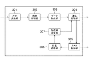
図3は、撮像装置100の機能構成図である。撮像装置100は、A/D変換部301と、現像処理部302と、データ形成部303と、通信処理部304と、カメラ制御部305と、位置処理部306と、配信順決定部307と、を有している。A/D変換部301は、各カメラ部101,102の撮像素子が受光した信号に対し、アナログデジタル変換を施し、撮像画像を得る。A/D変換部301により得られた撮像画像は、現像処理部302により現像処理が施され、データ形成部303により画像形成が行われ、通信処理部304へ送られる。通信処理部304は、ネットワーク120を介した通信を制御する。カメラ制御部305は、ユーザ装置110においてユーザ操作により入力された、カメラの制御命令を、通信処理部304を介して受け取る。そして、カメラ制御部305は、制御命令に従い、各カメラ部101,102の撮像を制御する。本処理は、撮像制御処理の一例である。カメラ制御部305はまた、PTZカメラ部101については、PTZ制御を行う。
FIG. 3 is a functional configuration diagram of the
位置処理部306は、各カメラ部101,102の撮像位置を特定する。位置処理部306は、PTZカメラ部101からは、PTZ制御が行われた結果の撮像位置を特定する。配信順決定部307は、通信処理部304が、各カメラ部101,102により撮像された複数の撮像画像を順番にユーザ装置110へ配信する際の配信順を決定する。
The
図4は、ユーザ装置110の表示部112に表示される表示画面例を示す図である。表示画面400には、撮像画像を表示する5つの領域が設けられている。連続する4つの領域401〜404には、各固定カメラ部102により撮像された複数の撮像画像が連続して表示される。ここで、説明の便宜上、図1に示す4つの固定カメラ部102をそれぞれ固定カメラ部A、固定カメラ部B、固定カメラ部C、固定カメラ部Dと称することとする。また、4つの領域401〜404には、それぞれ固定カメラA〜Dにより得られた撮像画像が表示されるものとする。そして、連続する領域401〜404に4つの撮像画像が配置されることにより、全体として1枚の連続した画像(全方位画像)になるものとする。
FIG. 4 is a diagram showing an example of a display screen displayed on the
また、領域405には、PTZカメラ部101により撮像された撮像画像が表示される。さらに、ユーザは、入力部113を操作することにより領域401〜404に表示された撮像画像において、注目したい領域を指定することができる。以下、ユーザ操作に応じて指定された領域を指定領域と称する。図4には、指定枠410により、領域402,403に渡る領域が指定された場合を示している。この場合には、指定枠410により指定される指定領域が撮像範囲となるように、PTZカメラ部101のPTZ機構が制御され、領域405には、指定枠410により指定される指定領域に対応した撮像画像がPTZカメラ部101の撮像画像として表示される。
Further, in the
図5は、撮像装置100による撮像画像の配信処理を示すフローチャートである。S500において、撮像装置100の通信処理部304は、通信部104を介して、カメラ部101,102により得られた撮像画像の配信を開始するよう制御する。通信処理部304は、前述の通り、切替部103を制御することにより、複数の撮像画像を、1つずつ順番に配信するよう制御する。これに対応し、通信部104は、複数の撮像装置を順番に配信する。なお、通信処理部304は、配信開始時にはデフォルトの配信順に従い撮像画像を配信するよう制御する。なお、デフォルトの配信順は、撮像装置100のROM106等に予め設定されているものとする。撮像装置100においては、例えば、PTZカメラ部101、固定カメラ部A〜Dの配信順がデフォルトとして予め設定されているものとする。配信開始後は、通信処理部304は、切替部103を制御することにより、配信順に従い、一定時間毎に撮像画像を切り替えながら、複数の撮像画像を順番に配信し続けるよう制御する。これに対応し、ユーザ装置110は、撮像装置100から撮像画像を順に受信し、受信した順に、表示画面400(図4)の各領域401〜405に撮像画像を表示し、新たな撮像画像を受信する度に表示を更新する。
FIG. 5 is a flowchart showing a distribution process of the captured image by the
次に、S501において、通信処理部304は、固定カメラ部102による撮像範囲内の領域の指定を受け付けたか否かを確認する。図4を参照しつつ説明したように、ユーザ装置110において、ユーザ操作により指定枠410が指定されたとする。この場合、ユーザ装置110は、指定枠410に対応する指定領域を特定し、指定領域をPTZカメラ部101の撮像範囲とするような制御命令を撮像装置100に送信する。通信処理部304は、この制御命令を受信した場合に、領域の指定を受け付けたと判断する。本処理は、領域の指定を受け付ける受付処理の一例である。通信処理部304は、領域の指定を受け付けると(S501でYES)、処理をS502へ進める。通信処理部304は、領域の指定を受け付けなかった場合には(S501でNO)、処理をS504へ進める。
Next, in S501, the
S502において、カメラ制御部305は、指定領域に応じた制御命令に基づいて、PTZカメラ部101の撮像範囲(PTZ撮像範囲と称する)を変更する。このとき、カメラ制御部305は、4つの固定カメラ部102の撮像画像から合成された全方位画像に対するPTZの撮像位置の座標情報を算出する。このPTZの撮像位置の座標情報の算出は、全方位画像を1面として座標を割り当て、その全方位画像の座標軸に対して、ユーザにより指定された指定枠の位置から座標に割り当て直すことで実現する。そして、PTZカメラ部101は、カメラ制御部305の制御の下、カメラ位置を変更位置の座標に従って移動する。次に、S503において、配信順決定部307は、各カメラ部101,102により得られた複数の撮像画像(本実施形態においては5つの撮像画像)の配信順を決定する。本処理については、図6等を参照しつつ後述する。
In S502, the
次に、S504において、通信処理部304は、S503において配信順が決定された場合には、決定された配信順で複数の撮像画像の各カメラ部101,102により得られた複数の撮像画像を順番に配信するよう切替部103を制御する。これに対応し、切替部103は、配信順に撮像画像を配信する。なお、配信順の決定が行われていない場合には、通信処理部304は、デフォルトの配信順に従い配信するよう制御する。これに対応し、通信部104は、配信順に従い、撮像画像を順番に外部装置としてのユーザ装置110に配信する。次に、S505において、通信処理部304は、配信を終了するか否かを判断する。通信処理部304は、配信を終了する場合には(S505でYES)、配信処理を終了する。通信処理部304は、配信を継続する場合には(S505でNO)、処理をS501へ進め、配信を継続する。以上の処理により、ユーザ装置110には、撮像画像が順番に送信される。これにより、表示画面400においては、配信順に応じて順に映像が表示、更新されていく。
Next, in S504, when the distribution order is determined in S503, the
図6は、配信順決定処理(S503)における詳細な処理を示すフローチャートである。S600において、位置処理部306は、全方位画像におけるPTZカメラ部101の撮像位置を算出する。次に、S601において、配信順決定部307は、位置処理部306により特定される、複数の固定カメラ部102の撮像範囲それぞれと、指定領域とが重なっているか否かを確認する。例えば、図4に示す例においては、指定枠410は、2つの領域402、403と重なっており、この場合には、指定領域が複数の撮像範囲と重なっていると判断される。配信順決定部307は、複数の撮像範囲と重なっている場合には(S601でYES)、処理をS602へ進める。配信順決定部307は、複数の撮像範囲と重なっていない場合、すなわち1つの撮像範囲のみと重なっている場合には(S601でNO)、処理をS606へ進める。
FIG. 6 is a flowchart showing detailed processing in the distribution order determination processing (S503). In S600, the
S602において、配信順決定部307は、指定領域と重なる撮像範囲の数と、いずれの撮像範囲と重なるのかを特定する。さらに、配信順決定部307は、指定領域と重なる複数の撮像範囲それぞれにおいて、指定領域との重なり部分の面積を算出し、重なり部分の面積が大きい順を特定する。次に、S603において、配信順決定部307は、PTZカメラ部101の配信順を1番に決定する。次に、S604において、配信順決定部307は、指定領域と撮像範囲が重なる固定カメラ部102に対し、面積の大きい順に2番以降の配信順を決定する。
In S602, the distribution
次に、S605において、配信順決定部307は、指定領域と撮像範囲が重ならない固定カメラ部102に対し、指定領域との位置関係に基づいて、指定領域と撮像範囲が重なる固定カメラ部102に対して決定された配信順以降の配信順を決定する。配信順決定部307は具体的には、指定領域との距離が近い順により先の配信順を割り当てる。以上の処理により、例えば、図4に示す例においては、PTZカメラ部101、領域402に対応する固定カメラB、領域403に対応する固定カメラC、領域401に対応する固定カメラA、領域404に対応する固定カメラDの配信順が決定される。
Next, in S605, the distribution
一方、S606においては、配信順決定部307は、PTZカメラ部101の配信順を1番に決定する。次に、S607において、配信順決定部307は、指定領域と撮像範囲が重なる固定カメラ部102の配信順を2番に決定する。次に、S608において、配信順決定部307は、指定領域と撮像範囲が重ならない固定カメラ部102に対し、指定領域との位置関係に基づいて、3番以降の配信順を決定する。なお、S608の処理は、S605の処理と同様である。なお、配信順決定処理は、固定カメラ部102の撮像範囲と指定領域の重なりの程度及び重なりの有無に基づいて、固定カメラ部102の撮像画像の配信順を決定する処理である。すなわち、配信順決定処理は、撮像範囲と指定領域の位置関係に基づいて、撮像画像の配信順を決定する決定処理の一例である。なお、配信順決定部307は、撮像範囲と指定領域の位置関係に基づいて、配信順を決定すればよく、そのための具体的な処理は、上述の内容に限定されるものではない。例えば、配信順決定部307は、指定領域の左上(ユーザによるドラッグ操作開始位置)がどの固定カメラ部102の撮像範囲に属するかを判定し、その撮像画像を配信する順序を決定してもよい。また、優先して配信する固定カメラ部102のフレームレートを他の固定カメラ部102よりも高くするようにしてもよい。
On the other hand, in S606, the distribution
以上のように、本実施形態の撮像装置100は、指定領域と重なる撮像画像を優先的に配信することができる。このように、撮像装置100は、撮像範囲が固定されたカメラにより撮像された撮像画像と、撮像範囲を変更可能なカメラにより撮像された撮像画像と、を適切に配信することができる。また、ユーザが注目している領域の撮像画像の損失を防ぐことができる。
As described above, the
(第2の実施形態)
次に、第2の実施形態に係る撮像システムについて、第1の実施形態に係る撮像システムと異なる点を説明する。図7は、第2の実施形態に係る撮像装置700の機能構成図である。撮像装置700は、第1の実施形態の撮像装置100と同様に、A/D変換部301と、現像処理部302と、データ形成部303と、通信処理部304と、カメラ制御部305と、位置処理部306と、を有している。撮像装置700はさらに、動体処理部701と、配信順決定部702とを有している。動体処理部701は、データ形成部303により得られた、固定カメラ部102の撮像画像から動体を検出し、検出した動体の動き量と、動く方向とを特定する。そして、動体処理部701は、撮像画像における動体の分布と、各動体の動き量及び動く方向を示す動体マップを生成する。動体マップは、通信処理部304により、ユーザ装置110に送信される。配信順決定部702は、動体処理部701により生成された動体マップ又は固定カメラ部102の撮像範囲と指定領域の位置関係に基づいて、各カメラ部101,102の撮像画像の配信順を決定する。
(Second embodiment)
Next, the image pickup system according to the second embodiment will be described as being different from the image pickup system according to the first embodiment. FIG. 7 is a functional configuration diagram of the image pickup apparatus 700 according to the second embodiment. Similar to the
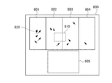
図8は、第2の実施形態に係るユーザ装置110の表示部112に表示される表示画面例を示す図である。表示画面800には、表示画面400(図4)と同様に、連続する4つの領域801〜804に固定カメラ部A〜Dにより撮像された撮像画像が表示される。そして、4つの領域801〜804の撮像画像は全体として1枚の連続した画像になるものとする。領域801〜804には、ユーザ操作に応じて指定枠810が表示される。また、領域805には、PTZカメラ部101により撮像された撮像画像が表示される。
FIG. 8 is a diagram showing an example of a display screen displayed on the
さらに、第2の実施形態に係るユーザ装置110は、撮像装置700から動体マップを受信し、動体マップに基づいて、領域801〜804に示す撮像画像上に、動体を示す矢印画像820を重畳して描画する。これにより、ユーザは、全方位画像における、動体の分布を把握することができる。例えば、図8の例では、領域801に表示された撮像領域に動体が多く存在し、領域804に表示された撮像領域においては動体が少ないと判断できる。なお、各矢印画像820の矢印の長さは動体の動き量を示し、矢印の向きは動体の動く方向を示す。
Further, the
図9は、第2の実施形態に係るユーザ装置110による配信処理を示すフローチャートである。S900において、撮像装置700の通信処理部304は、通信部104を介して、カメラ部101,102により得られた撮像画像の配信を開始する。本処理は、図5を参照しつつ説明したS500の処理と同様である。次に、S901において、動体処理部701は、複数の固定カメラ部102(固定カメラ部A〜D)の撮像画像それぞれに基づいて、動体を検出する。次に、S902において、動体処理部701は、動体検出の結果に基づいて、動体マッピングを生成する。そして、通信処理部304は、動体マップをユーザ装置110に送信する。これに対応し、ユーザ装置110は、受信した動体マップに基づいて、図8に示すように、撮像画像上に動体を示す矢印画像を重畳して表示する。
FIG. 9 is a flowchart showing a distribution process by the
次に、S903において、通信処理部304は、固定カメラ部102による撮像範囲内の領域の指定を受け付けたか否かを確認する。本処理は、S501の処理(図5)と同様である。通信処理部304は、領域の指定を受け付けると(S903でYES)、処理をS904へ進める。通信処理部304は、領域の指定を受け付けなかった場合には(S903でNO)、処理をS909へ進める。S904において、カメラ制御部305は、指定領域に応じた制御命令に基づいて、PTZ撮像範囲を変更する。本処理は、S502の処理(図5)と同様である。次に、S905において、配信順決定部702は、動体処理部701により生成された動体マップに基づいて、固定カメラ部A〜Dの優先度を決定する。配信順決定部702は、具体的には、撮像範囲に存在する動体の数が多いほど高い優先度を割り当てる。
Next, in S903, the
次に、S906において、配信順決定部702は、配信順の決定に関する設定を確認する。ここで、設定とは、配信順を決定する際に指定領域と動体マップの何れを優先するかの設定である。なお、いずれを優先するかは、ユーザ操作に応じて撮像装置700に設定されるものとする。配信順決定部702は、指定領域を優先する設定の場合には(S906でYES)、処理をS907へ進める。配信順決定部702は、動体マップを優先する設定の場合には(S906でNO)、処理をS908へ進める。
Next, in S906, the distribution
S907においては、配信順決定部702は、指定領域に基づいて、配信順を決定する。具体的には、配信順決定部702は、第1の実施形態において説明した配信順決定処理(S503)と同じ処理により配信順を決定する。一方、S908において、配信順決定部702は、動体マップに基づいて配信順を決定する。具体的には、配信順決定部702は、S905において決定した優先度順を配信順として決定する。すなわち、配信順決定部702は、動体の数が多い撮像画像を動体の数が少ない撮像画像よりも先に配信するような配信順を決定する。本処理は、動体の検出結果に応じて配信順を決定する処理の一例である。CPU105は、S907及びS908の処理の後、処理をS909へ進める。
In S907, the distribution
S909において、通信処理部304は、907又はS908において配信順が決定された場合には、決定された配信順で複数の撮像画像の各カメラ部101,102により得られた複数の撮像画像を順番に配信するよう切替部103を制御する。なお、配信順の決定が行われていない場合には、通信処理部304は、デフォルトの配信順に従い配信するよう制御する。次に、S910において、通信処理部304は、配信を終了するか否かを判断する。通信処理部304は、配信を終了する場合には(S910でYES)、配信処理を終了する。通信処理部304は、配信を継続する場合には(S910でNO)、処理をS901へ進め、配信を継続する。以上の処理により、ユーザ装置110には、撮像画像が順番に送信される。これにより、表示画面800においては、配信順に応じて順に映像が表示、更新され、動体マップに応じて、矢印画像も表示、更新される。
In S909, when the distribution order is determined in 907 or S908, the
例えば、図8の例で、指定領域が優先されたとする。この場合には、上記の処理により、PTZカメラ部101、領域802に対応する固定カメラB、領域803に対応する固定カメラC、領域801に対応する固定カメラA、領域804に対応する固定カメラDの配信順が決定される。また、図8の例で、動体マップが優先されたとする。この場合には、PTZカメラ部101、固定カメラA、固定カメラB、固定カメラB及び固定カメラDの配信順が決定される。なお、第2の実施形態に係る撮像システムのこれ以外の構成及び処理は、第1の実施形態に係る撮像システムの構成及び処理と同様である。
For example, in the example of FIG. 8, it is assumed that the designated area has priority. In this case, by the above processing, the
以上のように、第2に実施形態の撮像画像200は、動体マップ及び指定領域のいずれかを優先するような配信制御を行うことができる。
As described above, secondly, the captured
以上、本発明の好ましい実施形態について詳述したが、本発明は係る特定の実施形態に限定されるものではなく、特許請求の範囲に記載された本発明の要旨の範囲内において、種々の変形・変更が可能である。 Although the preferred embodiments of the present invention have been described in detail above, the present invention is not limited to the specific embodiments, and various modifications are made within the scope of the gist of the present invention described in the claims.・ Can be changed.
(その他の実施例)
本発明は、上述の実施形態の1以上の機能を実現するプログラムを、ネットワーク又は記憶媒体を介してシステム又は装置に供給し、そのシステム又は装置のコンピュータにおける1つ以上のプロセッサーがプログラムを読出し実行する処理でも実現可能である。また、1以上の機能を実現する回路(例えば、ASIC)によっても実現可能である。
(Other Examples)
The present invention supplies a program that realizes one or more functions of the above-described embodiment to a system or device via a network or storage medium, and one or more processors in the computer of the system or device reads and executes the program. It is also possible to realize the processing. It can also be realized by a circuit (for example, ASIC) that realizes one or more functions.
100 撮像装置
101 PTZカメラ部
102 固定カメラ部
103 切替部
104 通信部
100
Claims (8)
前記複数の撮像範囲の内の少なくとも1つにおいて、位置の指定を受け付ける受付手段と、
撮像範囲を変更可能な第2の撮像手段であって、前記指定に応じて、指定された前記位置に基づく第2の画像を撮像する第2の撮像手段と、
少なくとも、前記複数の第1の撮像手段によって撮像された複数の第1の画像を、所定の配信順序で、外部装置に配信する配信手段と
を有し、
前記複数の第1の画像は、前記外部装置において合成されて、表示画面の第1の領域に表示される画像であり、
前記第2の画像は、前記表示画面において、前記第1の領域とは異なる第2の領域に表示される画像であり、
前記配信手段は、前記指定に応じて、前記所定の配信順序を変更する
ことを特徴とする撮像装置。 A plurality of first imaging means for imaging a plurality of different imaging range, respectively,
A receiving means for accepting a position designation in at least one of the plurality of imaging ranges,
A second imaging means whose imaging range can be changed, and a second imaging means for capturing a second image based on the designated position according to the designation.
At least, a plurality of first image captured me by the plurality of first imaging means, in a predetermined delivery order, possess and distribution unit for distributing an external device,
The plurality of first images are images that are combined in the external device and displayed in the first area of the display screen.
The second image is an image displayed in a second area different from the first area on the display screen.
The distribution means is an imaging device characterized in that the predetermined distribution order is changed according to the designation.
前記配信手段は、前記決定手段により決定された配信順序となるよう、前記所定の配信順序を変更することを特徴とする請求項1に記載の撮像装置。 Further having a determining means for determining the delivery order based on the positional relationship between the plurality of imaging ranges and the designated position.
The imaging device according to claim 1, wherein the distribution means changes the predetermined distribution order so that the distribution order is determined by the determination means.
前記配信手段は、第1の設定においては、指定された前記位置に応じた配信順序で前記複数の第1の画像を配信し、第2の設定においては、動体の検出結果に応じた配信順序で前記複数の第1の画像を配信することを特徴とする請求項1乃至5の何れか1項に記載の撮像装置。 In the first images each of the plurality further includes a moving object detection means for detecting a moving object,
The delivery means is in the first set, to deliver the first images of the plurality in accordance with the said designated location delivery order, in the second set, in accordance with the detection result of the moving object delivery the imaging apparatus according to any one of claims 1 to 5, characterized in that delivering the first images of the plurality in order.
前記複数の撮像範囲の内の少なくとも1つにおいて、位置の指定を受け付ける受付ステップと、
前記受付ステップにおいて受け付けた前記指定に応じて、指定された前記位置に基づく第2の画像を撮像するよう、撮像範囲を変更可能な第2の撮像手段を制御する第2の撮像制御ステップと、
少なくとも、前記複数の第1の撮像手段によって撮像された複数の第1の画像を、所定の配信順序で、外部装置に配信する配信ステップと
を含み、
前記複数の第1の画像は、前記外部装置において合成されて、表示画面の第1の領域に表示される画像であり、
前記第2の画像は、前記表示画面において、前記第1の領域とは異なる第2の領域に表示される画像であり、
前記配信ステップにおいて、前記指定に応じて、前記所定の配信順序を変更する
ことを特徴とする撮像装置の制御方法。 A first imaging control step that controls a plurality of first imaging means so as to image a plurality of different imaging ranges,
A reception step that accepts a position designation in at least one of the plurality of imaging ranges, and
Depending on the specification received in previous Symbol receiving step, to image a second image based on said designated position, and a second imaging control step of controlling the second image pickup means capable of changing an imaging range ,
At least, a plurality of first image captured me by the plurality of first imaging means, in a predetermined delivery order, look including a distribution step of distributing the external device,
The plurality of first images are images that are combined in the external device and displayed in the first area of the display screen.
The second image is an image displayed in a second area different from the first area on the display screen.
A control method for an imaging device, characterized in that, in the distribution step, the predetermined distribution order is changed according to the designation.
それぞれ異なる複数の撮像範囲を撮像するよう、複数の第1の撮像手段を制御する第1の撮像制御ステップと、
前記複数の撮像範囲の内の少なくとも1つにおいて、位置の指定を受け付ける受付ステップと、
前記受付ステップにおいて受け付けた前記指定に応じて、指定された前記位置に基づく第2の画像を撮像するよう、撮像範囲を変更可能な第2の撮像手段を制御する第2の撮像制御ステップと、
少なくとも、前記複数の第1の撮像手段によって撮像された複数の第1の画像を、所定の配信順序で、外部装置に配信する配信ステップと
を実行させ、
前記複数の第1の画像は、前記外部装置において合成されて、表示画面の第1の領域に表示される画像であり、
前記第2の画像は、前記表示画面において、前記第1の領域とは異なる第2の領域に表示される画像であり、
前記配信ステップにおいて、前記指定に応じて、前記所定の配信順序を変更する
プログラム。 On the computer
A first imaging control step that controls a plurality of first imaging means so as to image a plurality of different imaging ranges,
A reception step that accepts a position designation in at least one of the plurality of imaging ranges, and
Depending on the specification received in previous Symbol receiving step, to image a second image based on said designated position, and a second imaging control step of controlling the second image pickup means capable of changing an imaging range ,
At least, a plurality of first image captured me by the plurality of first imaging means, in a predetermined delivery order, to perform a delivery step of delivering to an external device,
The plurality of first images are images that are combined in the external device and displayed in the first area of the display screen.
The second image is an image displayed in a second area different from the first area on the display screen.
A program that changes the predetermined delivery order according to the designation in the delivery step.
Priority Applications (3)
| Application Number | Priority Date | Filing Date | Title |
|---|---|---|---|
| JP2017176622A JP6907079B2 (en) | 2017-09-14 | 2017-09-14 | Imaging device, control method and program of imaging device |
| US16/121,428 US10771693B2 (en) | 2017-09-14 | 2018-09-04 | Imaging apparatus, control method for imaging apparatus, and storage medium |
| CN201811068484.8A CN109510967B (en) | 2017-09-14 | 2018-09-13 | Image pickup apparatus, control method of image pickup apparatus, and storage medium |
Applications Claiming Priority (1)
| Application Number | Priority Date | Filing Date | Title |
|---|---|---|---|
| JP2017176622A JP6907079B2 (en) | 2017-09-14 | 2017-09-14 | Imaging device, control method and program of imaging device |
Publications (3)
| Publication Number | Publication Date |
|---|---|
| JP2019054369A JP2019054369A (en) | 2019-04-04 |
| JP2019054369A5 JP2019054369A5 (en) | 2020-10-08 |
| JP6907079B2 true JP6907079B2 (en) | 2021-07-21 |
Family
ID=65631868
Family Applications (1)
| Application Number | Title | Priority Date | Filing Date |
|---|---|---|---|
| JP2017176622A Active JP6907079B2 (en) | 2017-09-14 | 2017-09-14 | Imaging device, control method and program of imaging device |
Country Status (3)
| Country | Link |
|---|---|
| US (1) | US10771693B2 (en) |
| JP (1) | JP6907079B2 (en) |
| CN (1) | CN109510967B (en) |
Families Citing this family (5)
| Publication number | Priority date | Publication date | Assignee | Title |
|---|---|---|---|---|
| KR102619271B1 (en) * | 2018-11-01 | 2023-12-28 | 한화비전 주식회사 | Video capturing device including plurality of cameras and video capturing system including the same |
| CN110781824B (en) * | 2019-10-25 | 2023-03-14 | 阿波罗智联(北京)科技有限公司 | Target detection and tracking method and device, electronic equipment and storage medium |
| JP7515265B2 (en) * | 2020-02-06 | 2024-07-12 | キヤノン株式会社 | Image capture device, image processing device control method, and image capture system |
| JP2022043930A (en) * | 2020-09-04 | 2022-03-16 | キヤノン株式会社 | Electronic apparatus |
| JP2022182840A (en) * | 2021-05-28 | 2022-12-08 | キヤノン株式会社 | Information processing apparatus, information processing system, information processing method, and program |
Family Cites Families (12)
| Publication number | Priority date | Publication date | Assignee | Title |
|---|---|---|---|---|
| JP5157116B2 (en) | 2006-10-04 | 2013-03-06 | カシオ計算機株式会社 | Imaging apparatus, composite image creation method, and program |
| US8253831B2 (en) * | 2008-11-29 | 2012-08-28 | International Business Machines Corporation | Location-aware event detection |
| JP5637385B2 (en) * | 2010-12-27 | 2014-12-10 | 清水建設株式会社 | Construction status recording system |
| CN102158689B (en) * | 2011-05-17 | 2013-12-18 | 无锡中星微电子有限公司 | Video monitoring system and method |
| KR101835802B1 (en) * | 2012-09-18 | 2018-03-08 | 브이아이디 스케일, 인크. | Region of interest video coding using tiles and tile groups |
| US9813618B2 (en) * | 2012-11-02 | 2017-11-07 | Diversified Innovations Fund, Lllp | Wide area imaging system and method |
| US9485425B1 (en) * | 2013-08-20 | 2016-11-01 | Pet Time Inc. | System that conserves power of a battery-powered streaming video camera |
| US20150244989A1 (en) * | 2014-02-27 | 2015-08-27 | Transcend Information, Inc. | Surveillance system, surveillance camera and method for security surveillance |
| US9251598B2 (en) * | 2014-04-10 | 2016-02-02 | GM Global Technology Operations LLC | Vision-based multi-camera factory monitoring with dynamic integrity scoring |
| TWI582517B (en) * | 2014-03-24 | 2017-05-11 | 群光電子股份有限公司 | Time-lapse photography method, its computer program product, and electrical device with image-capturing function thereof |
| US20160088326A1 (en) * | 2014-09-23 | 2016-03-24 | Watchcorp Holdings LLC | Distributed recording, managing, and accessing of surveillance data within a networked video surveillance system |
| JP6624800B2 (en) * | 2015-04-03 | 2019-12-25 | キヤノン株式会社 | Image processing apparatus, image processing method, and image processing system |
-
2017
- 2017-09-14 JP JP2017176622A patent/JP6907079B2/en active Active
-
2018
- 2018-09-04 US US16/121,428 patent/US10771693B2/en active Active
- 2018-09-13 CN CN201811068484.8A patent/CN109510967B/en active Active
Also Published As
| Publication number | Publication date |
|---|---|
| JP2019054369A (en) | 2019-04-04 |
| CN109510967B (en) | 2021-08-03 |
| CN109510967A (en) | 2019-03-22 |
| US20190082105A1 (en) | 2019-03-14 |
| US10771693B2 (en) | 2020-09-08 |
Similar Documents
| Publication | Publication Date | Title |
|---|---|---|
| JP6907079B2 (en) | Imaging device, control method and program of imaging device | |
| US10192284B2 (en) | Method for managing surveillance system with aid of panoramic map, and associated apparatus | |
| JP6226539B2 (en) | Information processing apparatus, information processing apparatus control method, and program | |
| CN106454065B (en) | Information processing apparatus and control method thereof | |
| JP6226538B2 (en) | Display control apparatus, display control method, and program | |
| KR20110108265A (en) | Control device, camera system and program | |
| WO2013168387A1 (en) | Display image formation device and display image formation method | |
| EP3739867A1 (en) | Imaging device, control apparatus, imaging method, and storage medium | |
| KR20130130544A (en) | Method and system for presenting security image | |
| JP6280011B2 (en) | Image transmission / reception system and method for performing data reduction processing based on region request | |
| CN110324572B (en) | Monitoring system, monitoring method, and non-transitory computer-readable storage medium | |
| KR20150071660A (en) | Control apparatus, imaging system, control method, and recording medium | |
| US9906710B2 (en) | Camera pan-tilt-zoom (PTZ) control apparatus | |
| JP7150456B2 (en) | IMAGING SYSTEM, INFORMATION PROCESSING DEVICE, CONTROL METHOD OF INFORMATION PROCESSING DEVICE, AND PROGRAM | |
| JP6608196B2 (en) | Information processing apparatus and information processing method | |
| JP5847591B2 (en) | Information processing apparatus, information processing method and program for information processing apparatus | |
| JP2019047492A (en) | Image processing apparatus, information processing system, information processing method, and program | |
| US20200396385A1 (en) | Imaging device, method for controlling imaging device, and recording medium | |
| JP7257778B2 (en) | Image processing device, image processing method | |
| KR20170055455A (en) | Camera system for compensating distortion of lens using super wide angle camera and Transport Video Interface Apparatus used in it | |
| JP2022012900A (en) | Information processing apparatus, display method, and program | |
| KR20120125037A (en) | Method for controlling surveillance system | |
| JP6643162B2 (en) | Control device, control method, imaging system, and program | |
| JP2011135212A (en) | Image confirmation apparatus | |
| JP2020092308A (en) | Imaging apparatus, control method, and program |
Legal Events
| Date | Code | Title | Description |
|---|---|---|---|
| A521 | Request for written amendment filed |
Free format text: JAPANESE INTERMEDIATE CODE: A523 Effective date: 20200827 |
|
| A621 | Written request for application examination |
Free format text: JAPANESE INTERMEDIATE CODE: A621 Effective date: 20200827 |
|
| A977 | Report on retrieval |
Free format text: JAPANESE INTERMEDIATE CODE: A971007 Effective date: 20210525 |
|
| TRDD | Decision of grant or rejection written | ||
| A01 | Written decision to grant a patent or to grant a registration (utility model) |
Free format text: JAPANESE INTERMEDIATE CODE: A01 Effective date: 20210601 |
|
| A61 | First payment of annual fees (during grant procedure) |
Free format text: JAPANESE INTERMEDIATE CODE: A61 Effective date: 20210630 |
|
| R151 | Written notification of patent or utility model registration |
Ref document number: 6907079 Country of ref document: JP Free format text: JAPANESE INTERMEDIATE CODE: R151 |