JP6906239B2 - Adjustable registration frame - Google Patents
Adjustable registration frame Download PDFInfo
- Publication number
- JP6906239B2 JP6906239B2 JP2018533790A JP2018533790A JP6906239B2 JP 6906239 B2 JP6906239 B2 JP 6906239B2 JP 2018533790 A JP2018533790 A JP 2018533790A JP 2018533790 A JP2018533790 A JP 2018533790A JP 6906239 B2 JP6906239 B2 JP 6906239B2
- Authority
- JP
- Japan
- Prior art keywords
- registration
- respect
- orientation
- image space
- rods
- Prior art date
- Legal status (The legal status is an assumption and is not a legal conclusion. Google has not performed a legal analysis and makes no representation as to the accuracy of the status listed.)
- Active
Links
- GDOPTJXRTPNYNR-UHFFFAOYSA-N CC1CCCC1 Chemical compound CC1CCCC1 GDOPTJXRTPNYNR-UHFFFAOYSA-N 0.000 description 1
Images


Classifications
-
- A—HUMAN NECESSITIES
- A61—MEDICAL OR VETERINARY SCIENCE; HYGIENE
- A61B—DIAGNOSIS; SURGERY; IDENTIFICATION
- A61B5/00—Measuring for diagnostic purposes; Identification of persons
- A61B5/05—Detecting, measuring or recording for diagnosis by means of electric currents or magnetic fields; Measuring using microwaves or radio waves
-
- A—HUMAN NECESSITIES
- A61—MEDICAL OR VETERINARY SCIENCE; HYGIENE
- A61B—DIAGNOSIS; SURGERY; IDENTIFICATION
- A61B10/00—Other methods or instruments for diagnosis, e.g. instruments for taking a cell sample, for biopsy, for vaccination diagnosis; Sex determination; Ovulation-period determination; Throat striking implements
- A61B10/02—Instruments for taking cell samples or for biopsy
- A61B10/0233—Pointed or sharp biopsy instruments
-
- A—HUMAN NECESSITIES
- A61—MEDICAL OR VETERINARY SCIENCE; HYGIENE
- A61B—DIAGNOSIS; SURGERY; IDENTIFICATION
- A61B17/00—Surgical instruments, devices or methods, e.g. tourniquets
- A61B17/34—Trocars; Puncturing needles
- A61B17/3403—Needle locating or guiding means
-
- A—HUMAN NECESSITIES
- A61—MEDICAL OR VETERINARY SCIENCE; HYGIENE
- A61B—DIAGNOSIS; SURGERY; IDENTIFICATION
- A61B34/00—Computer-aided surgery; Manipulators or robots specially adapted for use in surgery
- A61B34/20—Surgical navigation systems; Devices for tracking or guiding surgical instruments, e.g. for frameless stereotaxis
-
- A—HUMAN NECESSITIES
- A61—MEDICAL OR VETERINARY SCIENCE; HYGIENE
- A61B—DIAGNOSIS; SURGERY; IDENTIFICATION
- A61B5/00—Measuring for diagnostic purposes; Identification of persons
- A61B5/06—Devices, other than using radiation, for detecting or locating foreign bodies ; determining position of probes within or on the body of the patient
- A61B5/061—Determining position of a probe within the body employing means separate from the probe, e.g. sensing internal probe position employing impedance electrodes on the surface of the body
- A61B5/064—Determining position of a probe within the body employing means separate from the probe, e.g. sensing internal probe position employing impedance electrodes on the surface of the body using markers
-
- A—HUMAN NECESSITIES
- A61—MEDICAL OR VETERINARY SCIENCE; HYGIENE
- A61B—DIAGNOSIS; SURGERY; IDENTIFICATION
- A61B90/00—Instruments, implements or accessories specially adapted for surgery or diagnosis and not covered by any of the groups A61B1/00 - A61B50/00, e.g. for luxation treatment or for protecting wound edges
- A61B90/10—Instruments, implements or accessories specially adapted for surgery or diagnosis and not covered by any of the groups A61B1/00 - A61B50/00, e.g. for luxation treatment or for protecting wound edges for stereotaxic surgery, e.g. frame-based stereotaxis
- A61B90/11—Instruments, implements or accessories specially adapted for surgery or diagnosis and not covered by any of the groups A61B1/00 - A61B50/00, e.g. for luxation treatment or for protecting wound edges for stereotaxic surgery, e.g. frame-based stereotaxis with guides for needles or instruments, e.g. arcuate slides or ball joints
-
- A—HUMAN NECESSITIES
- A61—MEDICAL OR VETERINARY SCIENCE; HYGIENE
- A61B—DIAGNOSIS; SURGERY; IDENTIFICATION
- A61B90/00—Instruments, implements or accessories specially adapted for surgery or diagnosis and not covered by any of the groups A61B1/00 - A61B50/00, e.g. for luxation treatment or for protecting wound edges
- A61B90/39—Markers, e.g. radio-opaque or breast lesions markers
-
- A—HUMAN NECESSITIES
- A61—MEDICAL OR VETERINARY SCIENCE; HYGIENE
- A61B—DIAGNOSIS; SURGERY; IDENTIFICATION
- A61B90/00—Instruments, implements or accessories specially adapted for surgery or diagnosis and not covered by any of the groups A61B1/00 - A61B50/00, e.g. for luxation treatment or for protecting wound edges
- A61B90/50—Supports for surgical instruments, e.g. articulated arms
-
- G—PHYSICS
- G16—INFORMATION AND COMMUNICATION TECHNOLOGY [ICT] SPECIALLY ADAPTED FOR SPECIFIC APPLICATION FIELDS
- G16H—HEALTHCARE INFORMATICS, i.e. INFORMATION AND COMMUNICATION TECHNOLOGY [ICT] SPECIALLY ADAPTED FOR THE HANDLING OR PROCESSING OF MEDICAL OR HEALTHCARE DATA
- G16H40/00—ICT specially adapted for the management or administration of healthcare resources or facilities; ICT specially adapted for the management or operation of medical equipment or devices
- G16H40/60—ICT specially adapted for the management or administration of healthcare resources or facilities; ICT specially adapted for the management or operation of medical equipment or devices for the operation of medical equipment or devices
- G16H40/63—ICT specially adapted for the management or administration of healthcare resources or facilities; ICT specially adapted for the management or operation of medical equipment or devices for the operation of medical equipment or devices for local operation
-
- G—PHYSICS
- G16—INFORMATION AND COMMUNICATION TECHNOLOGY [ICT] SPECIALLY ADAPTED FOR SPECIFIC APPLICATION FIELDS
- G16H—HEALTHCARE INFORMATICS, i.e. INFORMATION AND COMMUNICATION TECHNOLOGY [ICT] SPECIALLY ADAPTED FOR THE HANDLING OR PROCESSING OF MEDICAL OR HEALTHCARE DATA
- G16H50/00—ICT specially adapted for medical diagnosis, medical simulation or medical data mining; ICT specially adapted for detecting, monitoring or modelling epidemics or pandemics
- G16H50/50—ICT specially adapted for medical diagnosis, medical simulation or medical data mining; ICT specially adapted for detecting, monitoring or modelling epidemics or pandemics for simulation or modelling of medical disorders
-
- A—HUMAN NECESSITIES
- A61—MEDICAL OR VETERINARY SCIENCE; HYGIENE
- A61B—DIAGNOSIS; SURGERY; IDENTIFICATION
- A61B17/00—Surgical instruments, devices or methods, e.g. tourniquets
- A61B2017/00535—Surgical instruments, devices or methods, e.g. tourniquets pneumatically or hydraulically operated
- A61B2017/00561—Surgical instruments, devices or methods, e.g. tourniquets pneumatically or hydraulically operated creating a vacuum
- A61B2017/00566—Surgical instruments, devices or methods, e.g. tourniquets pneumatically or hydraulically operated creating a vacuum fixation of form upon application of vacuum
-
- A—HUMAN NECESSITIES
- A61—MEDICAL OR VETERINARY SCIENCE; HYGIENE
- A61B—DIAGNOSIS; SURGERY; IDENTIFICATION
- A61B17/00—Surgical instruments, devices or methods, e.g. tourniquets
- A61B17/34—Trocars; Puncturing needles
- A61B17/3403—Needle locating or guiding means
- A61B2017/3405—Needle locating or guiding means using mechanical guide means
- A61B2017/3407—Needle locating or guiding means using mechanical guide means including a base for support on the body
-
- A—HUMAN NECESSITIES
- A61—MEDICAL OR VETERINARY SCIENCE; HYGIENE
- A61B—DIAGNOSIS; SURGERY; IDENTIFICATION
- A61B17/00—Surgical instruments, devices or methods, e.g. tourniquets
- A61B17/34—Trocars; Puncturing needles
- A61B17/3403—Needle locating or guiding means
- A61B2017/3405—Needle locating or guiding means using mechanical guide means
- A61B2017/3409—Needle locating or guiding means using mechanical guide means including needle or instrument drives
-
- A—HUMAN NECESSITIES
- A61—MEDICAL OR VETERINARY SCIENCE; HYGIENE
- A61B—DIAGNOSIS; SURGERY; IDENTIFICATION
- A61B34/00—Computer-aided surgery; Manipulators or robots specially adapted for use in surgery
- A61B34/20—Surgical navigation systems; Devices for tracking or guiding surgical instruments, e.g. for frameless stereotaxis
- A61B2034/2046—Tracking techniques
- A61B2034/2055—Optical tracking systems
-
- A—HUMAN NECESSITIES
- A61—MEDICAL OR VETERINARY SCIENCE; HYGIENE
- A61B—DIAGNOSIS; SURGERY; IDENTIFICATION
- A61B90/00—Instruments, implements or accessories specially adapted for surgery or diagnosis and not covered by any of the groups A61B1/00 - A61B50/00, e.g. for luxation treatment or for protecting wound edges
- A61B90/39—Markers, e.g. radio-opaque or breast lesions markers
- A61B2090/3954—Markers, e.g. radio-opaque or breast lesions markers magnetic, e.g. NMR or MRI
-
- A—HUMAN NECESSITIES
- A61—MEDICAL OR VETERINARY SCIENCE; HYGIENE
- A61B—DIAGNOSIS; SURGERY; IDENTIFICATION
- A61B90/00—Instruments, implements or accessories specially adapted for surgery or diagnosis and not covered by any of the groups A61B1/00 - A61B50/00, e.g. for luxation treatment or for protecting wound edges
- A61B90/39—Markers, e.g. radio-opaque or breast lesions markers
- A61B2090/3966—Radiopaque markers visible in an X-ray image
-
- A—HUMAN NECESSITIES
- A61—MEDICAL OR VETERINARY SCIENCE; HYGIENE
- A61B—DIAGNOSIS; SURGERY; IDENTIFICATION
- A61B90/00—Instruments, implements or accessories specially adapted for surgery or diagnosis and not covered by any of the groups A61B1/00 - A61B50/00, e.g. for luxation treatment or for protecting wound edges
- A61B90/39—Markers, e.g. radio-opaque or breast lesions markers
- A61B2090/3983—Reference marker arrangements for use with image guided surgery
-
- A—HUMAN NECESSITIES
- A61—MEDICAL OR VETERINARY SCIENCE; HYGIENE
- A61B—DIAGNOSIS; SURGERY; IDENTIFICATION
- A61B90/00—Instruments, implements or accessories specially adapted for surgery or diagnosis and not covered by any of the groups A61B1/00 - A61B50/00, e.g. for luxation treatment or for protecting wound edges
- A61B90/39—Markers, e.g. radio-opaque or breast lesions markers
- A61B2090/3991—Markers, e.g. radio-opaque or breast lesions markers having specific anchoring means to fixate the marker to the tissue, e.g. hooks
Description
本開示は、画像誘導インターベンション処置の分野に関し、特に、画像誘導処置の間に画像空間に対する自動化医療デバイスの位置及び方向を決定するためのシステム及び方法に関する。 The present disclosure relates to the field of image-guided interventional procedures, and in particular to systems and methods for determining the position and orientation of an automated medical device with respect to image space during image-guided intervention procedures.
近年の臨床診療に用いられる多くの日常治療は、生体検査、薬物送達及び他の診断及び治療処置のための、針及びカテーテル等の医療器具の経皮挿入に関与している。挿入処置の目的は、病変、腫瘍、臓器又は血管であり得る標的部位に安全且つ正確に適切な医療器具の先端を配置することである。このような医療器具の挿入を必要とする処置の例は、ワクチン接種、血液/流体の採取、局所麻酔、組織生検、カテーテル挿入、極低温アブレーション、電界アブレーション、小線源療法、神経手術、脳深部刺激及び様々な低侵襲手術を含む。 Many routine treatments used in clinical practice in recent years involve the percutaneous insertion of medical devices such as needles and catheters for biopsy, drug delivery and other diagnostic and therapeutic procedures. The purpose of the insertion procedure is to safely and accurately place the tip of a suitable medical device at a target site that may be a lesion, tumor, organ or blood vessel. Examples of procedures that require the insertion of such medical devices include vaccination, blood / fluid sampling, local anesthesia, tissue biopsy, catheter insertion, cryoablation, electrofield ablation, small radiation source therapy, neurosurgery, Includes deep brain stimulation and various minimally invasive surgeries.
軟組織内の針の誘導及び操縦は、良好な三次元調整、患者の生体構造の知識及び高水準の経験を必要とする複雑なタスクである。従って、こうした機能を行うために画像誘導自動化(例えば、ロボット)システムが提案されている。このようなシステムの中で、Stoianoviciの米国特許番号第7,008,373号、“System and method for robot targeting under fluoroscopy”;Glozman等の米国特許番号第8,348,861号、“Controlled Steering of a Flexible Needle”;Neubach等の米国特許番号第8,663,130号、“Ultrasound Guided Robot for Flexible Needle Steering”;Gupta等の米国出願公開第2006/0229641号、“Guidance and Insertion System”;Cleary等の米国出願公開第2014/0371584号、“Patient Mounted MRI and CT Compatible Robot for Needle Guidance in Interventional Procedures”;及びGlozman等の米国特許出願公開第2016/0249990号、“Needle Steering by Shaft Manipulation”に記載されたものが有る。 Guided and maneuvering needles in soft tissue is a complex task that requires good three-dimensional coordination, knowledge of the patient's biological structure and a high level of experience. Therefore, an image guidance automation (for example, a robot) system has been proposed to perform such a function. In such a system, US Pat. a Flexible Needle ”; U.S. Patent No. 8,663,130 of Neubach et al.,“ Ultrasound Guided Robot for Flexible Nedle Steering ”; U.S. Application Publication No. 2006/0229641 of Gupta et al. U.S. Patent Application Publication No. 2014/0371584, "Patient Monument MRI and CT Compatible Robot for Needle Guidance in International Procedures"; and Glozman et al., U.S. Patent Application Publication No. 2016/02499 There is something.
自動化挿入デバイスが使用される場合、通常、遠隔場所から標的に向かって、医療器具を正しく且つ正確に操縦するために、画像空間に対するデバイスの正確な位置が知られていなければならない。画像空間に対するデバイスの位置の決定は、典型的には、基準マーカを使用して行われる。基準マーカは、デバイス上の様々な場所に配置され、撮像システム(例えば、X線、CT、MRI)を使用して撮影された画像において検出することができる(複数の)材料から製造される。獲得された(複数の)画像におけるこうしたマーカの検出及び識別は、画像空間にデバイスを位置合わせする処理における重要なステップであり、これによりユーザは処置の中の任意の点において画像空間に対するデバイスの正確な位置及び/又は方向を知ることが可能になる。 When an automated insertion device is used, the exact position of the device with respect to image space must generally be known in order to properly and accurately steer the medical device from a remote location towards the target. Determining the position of the device with respect to image space is typically done using reference markers. Reference markers are placed at various locations on the device and are manufactured from (s) materials that can be detected in images taken using imaging systems (eg, X-rays, CT, MRI). The detection and identification of these markers in the acquired image is an important step in the process of aligning the device to the image space, which allows the user to use the device with respect to the image space at any point in the procedure. It becomes possible to know the exact position and / or direction.
レジストレーションマーカはデバイス自体に設置されているので、レジストレーション処理が行われることを可能にするために、その上に(複数の)マーカを含むデバイスの少なくとも一部が処置の間に撮影されるスキャンに含まれることが要求される。しかしながら、場合によっては、例えば、要求される挿入角度のために、デバイスと対象者の関心領域との間に大きな物理的距離が有り得る。その結果として、関心領域及びその上に(複数の)マーカを有するデバイスの少なくとも一部(典型的には、ロボットエンドエフェクタ)の両方を含むように非常に大きな容積をスキャンすることは、画像誘導処置にX線及びCT等の撮像様式が利用される場合、患者及び医療従事者を大量の放射線に曝すことになる。 Since the registration markers are located on the device itself, at least a portion of the device containing the markers (s) on it is imaged during the procedure to allow the registration process to take place. Required to be included in the scan. However, in some cases, there can be a large physical distance between the device and the subject's area of interest, for example due to the required insertion angle. As a result, scanning a very large volume to include both the region of interest and at least some of the devices (typically robot end effectors) with markers on it is image guidance. When imaging modes such as X-rays and CT are used for the procedure, patients and healthcare workers will be exposed to large amounts of radiation.
従って、スキャンされた容積において、デバイス又はその任意の部分の包含を必要とせずに、挿入処置の間の任意の所与の瞬間に(リアルタイムに)画像空間に対する挿入デバイスの位置及び方向を決定することができるシステム及び方法が必要とされている。 Thus, in the scanned volume, the position and orientation of the insertion device with respect to image space (in real time) at any given moment during the insertion procedure without the need for inclusion of the device or any portion thereof. There is a need for systems and methods that can.
明細書のこの節及び他の節において言及される各刊行物の開示は、参照によりその全体が本明細書に組み込まれる。 The disclosure of each publication referred to in this and other sections of the specification is incorporated herein by reference in its entirety.
デバイスがスキャン容積の外側に有る場合に、画像誘導医療処置(リアルタイム)の間の任意の点で画像空間に対する自動化医療デバイスの位置及び方向の決定を可能にするシステム及び方法が開示される。 Systems and methods are disclosed that allow the positioning and orientation of an automated medical device with respect to image space at any point during an image-guided medical procedure (real time) when the device is outside the scan volume.
一部の実装では、自動化挿入デバイスは、例えば、患者のベッドに結合され得るロボットアーム又は取り付けベースを含む。他の実装では、挿入デバイスは、身体に装着されてもよく、即ち、患者の身体に直接配置されて、そこに固定される。後者の場合、挿入デバイスは、(例えば、咳、姿勢調節等のため)患者が動くと、患者と共に動く。 In some implementations, the automated insertion device includes, for example, a robotic arm or mounting base that can be coupled to the patient's bed. In other implementations, the insertion device may be worn on the body, i.e., placed directly on the patient's body and secured therein. In the latter case, the insertion device moves with the patient as it moves (eg, for coughing, postural adjustment, etc.).
一部の実装によれば、挿入デバイス自体に配置されるレジストレーションマーカに加えて、対象者の身体に取り付けられるように構成される取り付けパッドの中/上に配置されるレジストレーション部材が提供される。取り付けパッドは、挿入デバイスに結合するように更に構成される。こうしたレジストレーション部材は、以下では「レジストレーションフレーム」又は「調節可能レジストレーションフレーム」と呼ばれる場合が有る。取り付けパッドは、調節可能レジストレーションフレームの少なくとも一部が関心領域の上に又は非常に接近して位置付けられるように、対象者の身体に取り付けられるべきである。 Some implementations provide a registration marker that is placed on the insertion device itself, as well as a registration member that is placed in / on a mounting pad that is configured to be mounted on the subject's body. NS. The mounting pad is further configured to couple to the insertion device. Such a registration member may be referred to hereinafter as a "registration frame" or an "adjustable registration frame". The mounting pad should be mounted on the subject's body so that at least a portion of the adjustable registration frame is positioned above or very close to the area of interest.
調節可能レジストレーションフレームは、パッドが身体におけるその場所に無関係に患者の身体の形状に適応するときに取り付けパッドと共に自身を調節することができるように、複数の自由度を含んでもよい。身体への配置の後で、取り付けパッド及び/又は調節可能レジストレーションフレームは、所定の空間構造においてより剛性の状態を採用させられてもよい。取り付けパッド及び調節可能レジストレーションフレームがより剛性の状態になると、挿入デバイスに対する調節可能レジストレーションフレームの位置は、固定され且つ不変になる。 The adjustable registration frame may include multiple degrees of freedom so that the pad can adjust itself with the mounting pad as it adapts to the shape of the patient's body regardless of its location on the body. After placement on the body, the mounting pads and / or adjustable registration frame may be allowed to adopt a more rigid state in a given spatial structure. As the mounting pads and adjustable registration frame become more rigid, the position of the adjustable registration frame with respect to the insertion device becomes fixed and immutable.
一部の実装によれば、調節可能レジストレーションフレームは、フレームが挿入デバイスに対して移動することができないように操作され得る媒体内に配置される。例えば、真空の印加、冷却/加熱等に応じて硬化し得る屈曲性取り付けパッドの内側に配置され得る。このような取り付けパッドは、少なくとも部分的に、真空を加えると互いに対して押し付けられる顆粒が充填されてもよく、それにより取り付けパッドが硬化させられる。用語「顆粒」は、コーヒー豆、稲、砂、プラスチックビーズ等の任意の適切なタイプの天然又は人口の顆粒のことを言ってもよい。 According to some implementations, the adjustable registration frame is placed in a medium that can be manipulated so that the frame cannot be moved with respect to the insertion device. For example, it can be placed inside a flexible mounting pad that can cure in response to vacuum application, cooling / heating, and the like. Such mounting pads may, at least in part, be filled with granules that are pressed against each other when vacuum is applied, thereby curing the mounting pads. The term "granule" may refer to any suitable type of natural or artificial granules such as coffee beans, rice, sand, plastic beads and the like.
Vogeleの米国特許出願公開第2012/0266898号、“Immobilization Device”は、成形可能真空操作クッションを開示している。しかしながら、クッションは、患者を動かなくさせるために使用され、調節可能レジストレーションフレームを含まない。更に、Vogeleでは、マーカが、アダプタプレートから突出するように、クッションの外部に取り付けられるアダプタプレートに固定される。このような突出マーカは、臨床医の視界又は行動を阻害し得る。更に、それらは損傷を受けるか又は壊される危険さえも有る。更に、患者にとって可視の突出マーカは威嚇的に見えるので、患者に対して負の心理的効果を有するかもしれない。 Voguele's US Patent Application Publication No. 2012/0266898, "Immobilization Device," discloses a moldable vacuum-operated cushion. However, the cushion is used to immobilize the patient and does not include an adjustable registration frame. Further, in Vogel, the marker is fixed to the adapter plate attached to the outside of the cushion so as to protrude from the adapter plate. Such protruding markers can obstruct the clinician's vision or behavior. Moreover, they are at risk of being damaged or even destroyed. In addition, visible protruding markers appear threatening to the patient and may have a negative psychological effect on the patient.
一部の実装では、開示された調節可能レジストレーションフレームは、それが臨床医の邪魔にならないように、取り付けパッドの内側に配置され、それは損傷を受けるか又は壊される可能性が低く、それは患者にとって不可視である。レジストレーション部材が取り付けパッドの外部に有る実装であっても、それらは患者及び臨床医の両方にとって目立たないように十分に小型で平坦である。 In some implementations, the disclosed adjustable registration frame is placed inside the mounting pad so that it does not get in the way of the clinician, it is less likely to be damaged or broken, it is the patient. Invisible to. Even in implementations where the registration members are external to the mounting pads, they are small and flat enough to be unobtrusive to both the patient and the clinician.
一部の実装では、調節可能レジストレーションフレーム自体が、例えば、冷却/加熱等によって、硬化又は「凍結」するように構成されてもよい。例えば、それは遠隔でロックされ得るジョイントを有してもよく、或いはそれは屈曲性であるが硬化するように遠隔で操作可能な材料から作られてもよい。 In some implementations, the adjustable registration frame itself may be configured to cure or "freeze", for example, by cooling / heating. For example, it may have a joint that can be locked remotely, or it may be made from a material that is flexible but can be remotely controlled to cure.
一部の実装では、調節可能レジストレーションフレームを共に形成するレジストレーション部材は、多関節ロッドアセンブリとして構成され、各多関節ロッドアセンブリは1つ以上のロッドから作られる。このような実装では、現在の画像空間に対する挿入デバイスの位置及び方向(即ち、現在の画像の座標系に関するその位置)は、現在の画像空間に対するロッドの位置及び方向、並びに挿入デバイスに対するロッドの以前に計算された(且つ固定された)位置及び方向に基づいて決定されてもよい。 In some implementations, the registration members that together form the adjustable registration frame are configured as articulated rod assemblies, each articulated rod assembly being made from one or more rods. In such an implementation, the position and orientation of the insertion device with respect to the current image space (ie, its position with respect to the coordinate system of the current image) is the position and orientation of the rod with respect to the current image space, as well as the rod's previous position with respect to the insertion device. It may be determined based on the calculated (and fixed) position and orientation in.
一部の実装では、レジストレーション部材は、半屈曲性要素/ストリップ(用語「半屈曲性要素」及び「半屈曲性ストリップ」は本開示では区別しないで使用され得る)として構成され、現在の画像空間に対する挿入デバイスの位置及び方向は、現在の画像空間に対する半屈曲性ストリップの位置及び方向、並びに挿入デバイスに対する半屈曲性ストリップの以前に計算された(且つ固定された)位置及び方向に基づいて決定される。 In some implementations, the registration member is configured as a semi-flexible element / strip (the terms "semi-flexible element" and "semi-flexible strip" may be used interchangeably in the present disclosure), and the current image. The position and orientation of the insertion device with respect to space is based on the position and orientation of the semi-flexible strip with respect to the current image space, as well as the previously calculated (and fixed) position and orientation of the semi-flexible strip with respect to the insertion device. It is determined.
一部の実装によれば、開示された調節可能レジストレーションフレームを使用するレジストレーション方法は以下の通りである。 According to some implementations, the registration method using the disclosed adjustable registration frame is as follows.
準備段階:挿入デバイスが取り付けパッドに結合された後で、取り付けパッド及び/又は調節可能レジストレーションフレームが更なる構造的安定状態にされると、初期スキャンが取得される。用語「スキャン」は、スキャンされる容積内で撮られる1つ以上の画像フレームのことを意味してもよい。用語「画像フレーム」、「フレーム」及び「スライス」は、本開示を通じて区別しないで使用される。初期スキャンは、全レジストレーションフレーム及び挿入デバイスを含み、それにより初期画像空間の座標系(CS)に関する挿入デバイスの位置及び方向(「並進及び回転」又は「変換」とも呼ばれる)並びに初期画像空間の座標系に関するレジストレーションフレームの位置及び方向が計算され得る。挿入デバイスの及び初期画像空間の座標系に関するレジストレーションフレームの位置及び方向が計算されると、挿入デバイスの座標系に関するレジストレーションフレームの位置及び方向、即ち、挿入デバイスに対する場所及び方向が計算され得る。挿入デバイスの座標系に関するレジストレーションフレームの位置及び方向は、取り付けパッド及び/又は調節可能レジストレーションフレームがその成形可能状態に戻されるまで変わらないままである。 Preparatory stage: An initial scan is obtained when the mounting pad and / or adjustable registration frame is further structurally stable after the insertion device has been coupled to the mounting pad. The term "scan" may mean one or more image frames taken within the volume to be scanned. The terms "image frame", "frame" and "slice" are used interchangeably throughout this disclosure. The initial scan includes the entire registration frame and insertion device, thereby the position and orientation of the insertion device (also referred to as "translation and rotation" or "transformation") with respect to the coordinate system (CS) of the initial image space and of the initial image space. The position and orientation of the registration frame with respect to the coordinate system can be calculated. Once the position and orientation of the registration frame with respect to the coordinate system of the insertion device and the initial image space has been calculated, the position and orientation of the registration frame with respect to the coordinate system of the insertion device, i.e. the location and orientation with respect to the insertion device, can be calculated. .. The position and orientation of the registration frame with respect to the coordinate system of the insertion device remains unchanged until the mounting pad and / or the adjustable registration frame is returned to its formable state.
リアルタイム:身体に取り付けられる挿入デバイスが利用される場合、画像空間に対する挿入デバイスの位置及び方向は、患者の動き(例えば、咳、姿勢調整)のために初期スキャンが行われた後で変化してもよい。しかしながら、取り付けパッド及び/又はレジストレーションフレームが更なる構造的安定状態に維持される限り、挿入デバイスに対するレジストレーションフレームの位置及び方向は変化しないままである。従って、レジストレーションフレームの動きは、必然的に、挿入デバイスの同一の動きを示す。リアルタイムスキャンは、関心領域及びレジストレーションフレームの最低限必要な部分のみを含むように容積が最小化される。各リアルタイム画像はレジストレーションフレームの少なくとも一部を含み、それによりリアルタイム画像CSに関するレジストレーションフレームの変換が計算され得る。この変換は、初期スキャンから知られる挿入デバイスCSに関するレジストレーションフレームの変換と共に、挿入処置を通じて取得される各リアルタイム画像のCSに関する挿入デバイスの変換を決定するために使用される。 Real-time: When a body-mounted insertion device is utilized, the position and orientation of the insertion device with respect to image space changes after an initial scan is performed for patient movement (eg, cough, postural adjustment). May be good. However, the position and orientation of the registration frame with respect to the insertion device remains unchanged as long as the mounting pad and / or the registration frame is maintained in a more structurally stable state. Therefore, the movement of the registration frame necessarily shows the same movement of the insertion device. The real-time scan is volume minimized to include only the area of interest and the minimum required portion of the registration frame. Each real-time image contains at least a portion of the registration frame, whereby the conversion of the registration frame with respect to the real-time image CS can be calculated. This conversion is used to determine the conversion of the insertion device for the CS of each real-time image acquired through the insertion procedure, as well as the conversion of the registration frame for the insertion device CS known from the initial scan.
関心領域から離れているかもしれない又は挿入の角度のためにスキャンされる大容積を必要とする挿入デバイスを含む代わりに、スキャン容積が関心領域の上又はそれに非常に接近して配置され得る調節可能フレームの最小部分のみを含むので、本開示のデバイス、システム及び方法はスキャン容積を制限することが可能である。従って、患者の及び医療従事者の放射線への被曝が最小化される。 Adjustments in which the scanned volume can be placed above or very close to the region of interest instead of including an insertion device that may be away from the region of interest or requires a large volume to be scanned due to the angle of insertion. The devices, systems and methods of the present disclosure are capable of limiting the scan volume as they include only the smallest portion of the possible frame. Therefore, radiation exposure of patients and health care workers is minimized.
従って、本開示に記載されたデバイスの例示的な実装に従って、画像誘導処置の間に画像空間に対する自動化医療デバイスの位置及び方向を決定するためのシステムであって、
(i)対象者の身体に取り付けられ且つ自動化医療デバイスをそこに結合するように適合される少なくとも1つの屈曲性要素、及び
少なくとも1つの屈曲性要素の上又は中に配置される1つ以上のレジストレーション部材を備える取り付け装置であって、
少なくとも1つの屈曲性要素及び1つ以上のレジストレーション部材の少なくとも1つは成形可能状態から更なる構造的安定状態に変換可能であり、そのため変換に応じて、1つ以上の部材と自動化医療デバイスとの間に実質的に相対運動が無くなり、且つ1つ以上のレジストレーション部材の間で相対運動が無くなる、取り付け装置と、
(ii)撮像システムから取得される画像における1つ以上のレジストレーション部材の少なくとも一部を検出すること、
画像空間に対する1つ以上のレジストレーション部材の少なくとも一部の位置及び方向を決定すること、
画像空間に対する1つ以上のレジストレーション部材の少なくとも一部及び自動化医療デバイスと1つ以上のレジストレーション部材との間の既定の関連性に基づいて、画像空間に対する自動化医療デバイスの位置及び方向を決定すること
を行うように構成されるプロセッサと
を備える、システムが提供される。
Accordingly, according to the exemplary implementation of the device described in the present disclosure, a system for determining the position and orientation of an automated medical device with respect to image space during an image-guided procedure.
(I) At least one flexor element attached to the subject's body and adapted to connect an automated medical device therein, and one or more placed on or within at least one flexor element. A mounting device equipped with a registration member
At least one of the flexible elements and one or more resisting members can be transformed from a moldable state to a further structurally stable state, and thus, depending on the conversion, one or more members and an automated medical device. With a mounting device, there is virtually no relative motion between the members and between one or more registration members.
(Ii) Detecting at least a portion of one or more registration members in an image acquired from an imaging system.
Determining the position and orientation of at least a portion of one or more registration members with respect to image space,
The position and orientation of the automated medical device with respect to the image space is determined based on at least a portion of the one or more registration members with respect to the image space and a predetermined association between the automated medical device and the one or more registration members. A system is provided with a processor configured to do so.
このようなシステムでは、少なくとも1つの屈曲性要素は、屈曲性カバーの中に包み込まれる顆粒材料を含んでもよい。このような場合、少なくとも1つの屈曲性要素は、真空を加えることによって成形可能状態から更なる構造的安定状態に変換されるように構成されてもよい。更に、1つ以上のレジストレーション部材は、少なくとも1つの屈曲性要素の屈曲性カバーに結合可能であってもよい。 In such a system, at least one flexible element may include a granular material that is encapsulated within the flexible cover. In such cases, at least one flexible element may be configured to be transformed from a moldable state to a further structurally stable state by applying vacuum. Further, the one or more registration members may be connectable to the flexible cover of at least one flexible element.
このようなシステムの他の実装では、1つ以上のレジストレーション部材は、多関節ロッドアセンブリを備えてもよく、各多関節ロッドアセンブリは1つ以上のロッドを備えてもよい。このようなシステムでは、プロセッサは、1つ以上のロッドの任意の2つの間の空間角度を計算するように更に構成されるべきである。1つ以上のロッドの任意の2つの間の最小距離を計算し、2つのロッドの各々における最小距離点、及び画像空間における2つのロッドのロッド座標系さえも計算するように更に構成されてもよい。後者の場合、プロセッサが画像空間に対する1つ以上のレジストレーション部材の少なくとも一部の位置及び方向を決定するように構成されることは、プロセッサが画像空間に対する少なくとも1つのロッド座標系の位置及び方向を計算するように構成されることを含んでもよい。 In other implementations of such systems, one or more registration members may comprise an articulated rod assembly, and each articulated rod assembly may comprise one or more rods. In such a system, the processor should be further configured to calculate the spatial angle between any two of one or more rods. It may be further configured to calculate the minimum distance between any two of one or more rods, the minimum distance point in each of the two rods, and even the rod coordinate system of the two rods in image space. good. In the latter case, the processor is configured to determine the position and orientation of at least a portion of one or more registration members with respect to the image space so that the processor determines the position and orientation of at least one rod coordinate system with respect to the image space. May include being configured to calculate.
上記のシステムの何れかにおいて、1つ以上のレジストレーション部材は半屈曲性要素を含んでもよく、半屈曲性要素の各々に対して、画像空間における半屈曲性要素の既定の部分を含む平面を決定するように更に構成されてもよい。半屈曲性要素の既定の部分は、半屈曲性要素の長さに沿って半屈曲性要素の幅の中心点を接続する線であるべきであり、この場合、プロセッサは、画像空間における平面の任意の2つの間の角度、又は平面の任意の2つの交線を計算するように更に構成されてもよい。後者の場合、プロセッサは、交線の任意の2つに対して、2つの交線の少なくとも1つにおける最小距離点、及び2つの交線の交線座標系を計算するように更に構成されてもよい。このようなプロセッサが画像空間に対する1つ以上のレジストレーション部材の少なくとも一部の位置及び方向を決定するように構成される場合、それは画像空間に対する少なくとも1つの交線座標系の位置及び方向を計算するように構成されてもよい。 In any of the above systems, one or more registration members may include semi-flexible elements, for each of the semi-flexible elements a plane containing a predetermined portion of the semi-flexible elements in image space. It may be further configured to determine. The default portion of the semi-flexible element should be a line connecting the center points of the width of the semi-flexible element along the length of the semi-flexible element, in which case the processor is a plane in image space. It may be further configured to calculate the angle between any two, or the line of intersection of any two planes. In the latter case, the processor is further configured to calculate the minimum distance point at at least one of the two lines of intersection and the line-of-line coordinate system of the two lines of intersection for any two of the lines of intersection. May be good. When such a processor is configured to determine the position and orientation of at least a portion of one or more registration members with respect to image space, it calculates the position and orientation of at least one line of intersection coordinate system with respect to image space. It may be configured to do so.
半屈曲性要素を含む更なるこのような実装によれば、1つ以上のレジストレーション部材は、1つ以上の半屈曲性要素に実質的に水平に配置される1つ以上の糸を更に含んでもよく、プロセッサは、1つ以上の半屈曲性要素と1つ以上の糸との間の少なくとも1つの交点を検出するように更に構成される。更に、プロセッサは、少なくとも1つ交点の1つ以上の座標系を計算するように更に構成されてもよい。後者の場合、プロセッサが画像空間に対する1つ以上のレジストレーション部材の少なくとも一部の位置及び方向を決定するように構成されることは、プロセッサが画像空間に対する少なくとも1つの交点の1つ以上の座標系の位置及び方向を計算するように構成されることを含んでもよい。 According to further such implementations that include semi-flexible elements, one or more registration members further include one or more threads that are placed substantially horizontally on one or more semi-flexible elements. However, the processor is further configured to detect at least one intersection between one or more semi-flexible elements and one or more threads. Further, the processor may be further configured to compute one or more coordinate systems of at least one intersection. In the latter case, the processor is configured to determine the position and orientation of at least a portion of one or more registration members with respect to the image space, that is, one or more coordinates of the processor at least one intersection with respect to the image space. It may include being configured to calculate the position and orientation of the system.
上記のシステムの更なる実装では、プロセッサは、撮像システムから画像を取得するように更に構成される。 In a further implementation of the above system, the processor is further configured to acquire an image from the imaging system.
更なる実装は上記のようなシステムを含んでもよく、取り付け装置は、少なくとも1つの屈曲性要素に結合可能なベースプレートを更に備え、ベースプレートは自動化医療デバイスを受け入れるように構成される。このような場合、少なくとも1つの屈曲性要素は配置要素及び配置要素とは別のレジストレーション要素を備えてもよく、配置要素はベースプレートを含み、レジストレーション要素は1つ以上のレジストレーション部材を含む。 Further implementations may include systems such as those described above, the attachment device further comprising a base plate capable of coupling to at least one flexible element, the base plate being configured to accept an automated medical device. In such a case, at least one flexible element may include an arrangement element and a registration element separate from the arrangement element, the arrangement element including a base plate, and the registration element including one or more registration members. ..
更に、先に記載されたシステムの何れかにおいて、取り付け装置は、少なくとも1つの屈曲性要素を対象者の身体に固定するように構成される1つ以上のストラップを更に含んでもよい。最後に、撮像システムは、X線透視システム、CTシステム、コーンビームCTシステム、CT透視システム、MRIシステム、及び超音波システムの任意の1つであってもよい。 Further, in any of the systems described above, the attachment device may further include one or more straps configured to secure at least one flexible element to the subject's body. Finally, the imaging system may be any one of an X-ray fluoroscopy system, a CT system, a cone beam CT system, a CT fluoroscopy system, an MRI system, and an ultrasound system.
本開示による例示的なシステムの代替的な実装は、画像誘導処置の間に画像空間に対する自動化医療デバイスの位置及び方向を決定するためのシステムであって、システムは、
(i)対象者の身体に取り付けられ且つ自動化医療デバイスをそこに結合するように適合される少なくとも1つの屈曲性要素、及び
少なくとも1つの屈曲性要素の上又は中に配置される1つ以上のレジストレーション部材を備える取り付け装置と、
(ii)取り付け装置及びそこに結合される自動化医療デバイスの1つ以上の初期画像を取得すること、
1つ以上の初期画像において1つ以上のレジストレーション部材を検出すること、
1つ以上のレジストレーション部材の間の関連性を定義するために、1つ以上の既定の幾何学的パラメータを計算すること、
1つ以上の既定の幾何学的パラメータの計算された値を記憶すること、
1つ以上の初期画像の画像空間に対する1つ以上のレジストレーション部材の位置及び方向を計算すること、
1つ以上の初期画像の画像空間に対する自動化医療デバイスの位置及び方向を計算すること、
自動化医療デバイスの及び1つ以上の初期画像の画像空間に対する1つ以上のレジストレーション部材の計算された位置及び方向に基づいて、自動化医療デバイスに対する1つ以上のレジストレーション部材の位置及び方向を決定すること、
関心領域の1つ以上のリアルタイム画像を取得することであって、1つ以上のリアルタイム画像は1つ以上のレジストレーション部材の少なくとも1つの少なくとも2つの部分を含むこと、
1つ以上のリアルタイム画像における1つ以上のレジストレーション部材の少なくとも1つの少なくとも2つの部分を検出すること、
1つ以上のリアルタイム画像における1つ以上のレジストレーション部材の少なくとも1つの少なくとも2つの部分の間の関連性を定義するために、リアルタイムで1つ以上の既定の幾何学的パラメータを計算すること、
1つ以上の既定の幾何学的パラメータの記憶された値と1つ以上の既定の幾何学的パラメータのリアルタイム値とを比較して、1つ以上のレジストレーション部材の少なくとも1つを識別すること、
1つ以上のリアルタイム画像の画像空間に対する1つ以上のレジストレーション部材の識別された少なくとも1つの位置及び方向を計算すること、及び
1つ以上のリアルタイム画像の画像空間に対する1つ以上のレジストレーション部材の識別された少なくとも1つの計算された位置及び方向、及び自動化医療デバイスに対する1つ以上のレジストレーション部材の少なくとも1つの決定された位置及び方向に基づいて、1つ以上のリアルタイム画像の画像空間に対する自動化医療デバイスの位置及び方向を決定すること
を行うように構成されるプロセッサと
を更に含む。
An alternative implementation of the exemplary system according to the present disclosure is a system for determining the position and orientation of an automated medical device with respect to image space during an image-guided procedure.
(I) At least one flexor element attached to the subject's body and adapted to connect an automated medical device therein, and one or more placed on or within at least one flexor element. A mounting device with a registration member and
(Ii) Obtaining one or more initial images of the attachment device and the automated medical device coupled therein.
Detecting one or more registration members in one or more initial images,
Computing one or more default geometric parameters to define the association between one or more registration members,
Remembering the calculated values of one or more default geometric parameters,
Calculating the position and orientation of one or more registration members with respect to the image space of one or more initial images,
Calculating the position and orientation of an automated medical device with respect to the image space of one or more initial images,
Determine the position and orientation of one or more registration members with respect to the automated medical device based on the calculated position and orientation of the one or more registration members with respect to the image space of the automated medical device and one or more initial images. To do,
Acquiring one or more real-time images of a region of interest, wherein the one or more real-time images include at least one or at least two parts of one or more registration members.
Detecting at least one or at least two parts of one or more registration members in one or more real-time images.
Computing one or more predetermined geometric parameters in real time to define the association between at least one at least two parts of one or more registration members in one or more real-time images.
Identifying at least one of the registration members by comparing the stored values of one or more default geometric parameters with the real-time values of one or more default geometric parameters. ,
Compute at least one identified position and orientation of one or more registration members with respect to the image space of one or more real-time images, and one or more registration members with respect to the image space of one or more real-time images. With respect to the image space of one or more real-time images based on at least one identified position and orientation of, and at least one determined position and orientation of one or more resisting members with respect to an automated medical device. It further includes a processor configured to determine the location and orientation of the automated medical device.
このようなシステムでは、少なくとも1つの屈曲性要素は、成形可能状態から更なる構造的安定状態に変換されるように構成され、少なくとも1つの屈曲性要素が更なる構造的安定状態に変換されると、互いに対する及び自動化医療デバイスに対する1つ以上のレジストレーション部材の動きが実質的に無くなるはずである。このようなシステムでは、1つ以上のレジストレーション部材は、成形可能状態から更なる構造的安定状態に変換されるように構成され、それにより、変換に応じて、互いに対する及び自動化医療デバイスに対する1つ以上のレジストレーション部材の動きが実質的に無くなるはずである。 In such a system, at least one flexible element is configured to be transformed from a moldable state into a further structurally stable state, and at least one flexible element is transformed into a further structurally stable state. And there should be virtually no movement of one or more resisting members with respect to each other and with respect to the automated medical device. In such a system, one or more registration members are configured to transform from a moldable state to a further structurally stable state, thereby one for each other and for an automated medical device, depending on the conversion. There should be virtually no movement of one or more registration members.
先の2つの段落に記載されたシステムでは、1つ以上のレジストレーション部材は、多関節ロッドアセンブリを備えてもよく、各多関節ロッドアセンブリは1つ以上のロッドを備えてもよい。代替的に、1つ以上のレジストレーション部材は、半屈曲性要素を含んでもよい。更に、既定の幾何学的パラメータは、角度、距離、長さ、形状、平面、相対位置及び座標系の1つ以上を含んでもよい。最後に、こうしたシステムの何れかが、自動化医療デバイスに取り付けられる1つ以上のレジストレーションマーカを更に備えてもよく、プロセッサは、1つ以上のレジストレーションマーカを検出するように更に構成される。 In the systems described in the previous two paragraphs, one or more registration members may comprise an articulated rod assembly, and each articulated rod assembly may comprise one or more rods. Alternatively, the one or more registration members may include a semi-flexible element. In addition, the default geometric parameters may include one or more of angles, distances, lengths, shapes, planes, relative positions and coordinate systems. Finally, any of these systems may further include one or more registration markers attached to the automated medical device, and the processor is further configured to detect one or more registration markers.
更に他の例示的な実装は、プロセッサと、対象者の身体に取り付けられ且つ自動化医療デバイスをそこに結合するように適合される少なくとも1つの屈曲性要素、及び少なくとも1つの屈曲性要素の上又は中に配置される1つ以上のレジストレーション部材を有する取り付け装置とを備えるシステムを使用して、画像誘導処置の間に画像空間に対する自動化医療デバイスの位置及び方向を決定するための方法を含んでもよく、少なくとも1つの屈曲性要素及び1つ以上のレジストレーション部材の少なくとも1つは成形可能状態から更なる構造的安定状態に変換可能であり、そのため変換に応じて、互いに対する及び自動化医療デバイスに対する1つ以上のレジストレーション部材の動きが実質的に無くなり、方法は、
(i)少なくとも1つの屈曲性要素及び1つ以上のレジストレーション部材の少なくとも1つの成形可能状態から更なる構造的安定状態への変換の後で、撮像システムから取得される画像において1つ以上のレジストレーション部材の少なくとも1つの少なくとも2つの部分を検出するステップと、
(ii)画像空間に対する1つ以上のレジストレーション部材の少なくとも1つの少なくとも2つの部分の位置及び方向を決定するステップと、
(iii)画像空間に対する1つ以上のレジストレーション部材の少なくとも1つの少なくとも2つの部分の決定された位置及び方向、並びに自動化医療デバイスと1つ以上のレジストレーション部材との間の既定の関連性に基づいて、画像空間に対する自動化医療デバイスの位置及び方向を決定するステップと
を含む。
Yet another exemplary implementation is on or over the processor and at least one flexible element that is attached to the subject's body and adapted to couple an automated medical device therein. Including a method for determining the position and orientation of an automated medical device with respect to image space during an image-guided procedure using a system with a mounting device having one or more resisting members placed therein. Well, at least one of the flexible elements and one or more resisting members can be transformed from a moldable state to a further structurally stable state, and thus to each other and to automated medical devices depending on the conversion. The movement of one or more registration members is virtually eliminated, and the method is:
(I) One or more in the image acquired from the imaging system after conversion of at least one flexible element and one or more registration members from at least one formable state to a further structurally stable state. The step of detecting at least one or at least two parts of the registration member,
(Ii) A step of determining the position and orientation of at least one at least two parts of one or more registration members with respect to the image space.
(Iii) To the determined position and orientation of at least one at least two parts of one or more registration members with respect to the image space, and the default association between the automated medical device and one or more registration members. Includes steps to determine the position and orientation of the automated medical device with respect to image space based on it.
このような方法では、1つ以上のレジストレーション部材は、多関節ロッドアセンブリを備えてもよく、各多関節ロッドアセンブリは1つ以上のロッドを備えてもよい。このような状況では、画像空間に対する1つ以上のレジストレーション部材の少なくとも1つの少なくとも2つの部分の位置及び方向を決定するステップは、
1つ以上のロッドの少なくとも2つの間の最小距離、少なくとも2つのロッドにおける最小距離点、及び少なくとも2つのロッドのロッド座標系を計算すること、及び
画像空間に対するロッド座標系の位置及び方向を計算すること
を含んでもよい。
In such a method, one or more registration members may include an articulated rod assembly, and each articulated rod assembly may include one or more rods. In such situations, the step of determining the position and orientation of at least one at least two parts of one or more registration members with respect to image space is
Calculate the minimum distance between at least two rods of one or more rods, the minimum distance point in at least two rods, and the rod coordinate system of at least two rods, and the position and orientation of the rod coordinate system with respect to image space. May include doing.
方法は、1つ以上のロッドの少なくとも2つの間の空間角度を計算するステップを更に含んでもよい。更に、1つ以上のレジストレーション部材は、半屈曲性要素を含んでもよく、この場合、画像空間に対する1つ以上のレジストレーション部材の少なくとも1つの少なくとも2つの部分の位置及び方向を決定するステップは、半屈曲性要素の少なくとも2つに対して、半屈曲性要素の少なくとも既定の部分を含む平面を見つけることを含んでもよい。画像空間に対する1つ以上のレジストレーション部材の少なくとも1つの少なくとも2つの部分の位置及び方向を決定するステップは、次に、平面の任意の2つの交線を見つけることを更に含んでもよい。これが行われると、画像空間に対する1つ以上のレジストレーション部材の少なくとも1つの少なくとも2つの部分の位置及び方向を決定するステップは、任意の2つの交線に対して、2つの交線の間の最小距離、2つの交線の少なくとも1つにおける最小距離点、及び2つの交線の交線座標系を計算することを更に含んでもよい。画像空間に対する1つ以上のレジストレーション部材の少なくとも1つの少なくとも2つの部分の位置及び方向を決定するステップは、次に、画像空間に対する交線座標系の位置及び方向を計算することを更に含んでもよい。 The method may further include the step of calculating the spatial angle between at least two of one or more rods. Further, the one or more resisting members may include a semi-flexible element, in which case the step of determining the position and orientation of at least one at least two parts of the one or more resisting members with respect to the image space is , For at least two of the semi-flexible elements, may include finding a plane containing at least a predetermined portion of the semi-flexible element. The step of determining the position and orientation of at least one at least two parts of one or more registration members with respect to image space may then further include finding any two lines of intersection in the plane. When this is done, the step of determining the position and orientation of at least one at least two parts of one or more registration members with respect to image space is between the two lines of intersection for any two lines of intersection. It may further include calculating the minimum distance, the minimum distance point at at least one of the two lines of intersection, and the line-of-line coordinate system of the two lines of intersection. The step of determining the position and orientation of at least one at least two parts of one or more registration members with respect to image space may then further include calculating the position and orientation of the line of intersection coordinate system with respect to image space. good.
上記の方法の何れかは、任意の2つの平面の間の角度を計算するステップを更に含んでもよい。 Any of the above methods may further include the step of calculating the angle between any two planes.
更に、1つ以上のレジストレーション部材が半屈曲性要素を含む上記の方法の何れかにおいて、1つ以上のレジストレーション部材は、1つ以上の半屈曲性要素に実質的に水平に配置される1つ以上の糸を更に含んでもよく、画像空間に対する1つ以上のレジストレーション部材の少なくとも1つの少なくとも2つの部分の位置及び方向を決定するステップは、1つ以上の半屈曲性要素と1つ以上の糸との間の少なくとも1つの交点を検出することを含んでもよい。このような状況では、画像空間に対する1つ以上のレジストレーション部材の少なくとも1つの少なくとも2つの部分の位置及び方向を決定するステップは、少なくとも1つの交点の1つ以上の座標系を計算することを更に含んでもよい。画像空間に対する1つ以上のレジストレーション部材の少なくとも1つの少なくとも2つの部分の位置及び方向を決定するステップは、次に、画像空間に対する少なくとも1つの交点の1つ以上の座標系の位置及び方向を計算することを更に含んでもよい。 Further, in any of the above methods where the one or more resisting members include a semi-flexible element, the one or more resisting members are arranged substantially horizontally on the one or more semi-flexible elements. One or more threads may be further included, and the step of determining the position and orientation of at least one at least two parts of the one or more resisting members with respect to the image space is one with one or more semi-flexible elements. It may include detecting at least one intersection with the above threads. In such situations, the step of determining the position and orientation of at least one at least two parts of one or more registration members with respect to image space is to calculate one or more coordinate systems of at least one intersection. Further may be included. The step of determining the position and orientation of at least one at least two parts of one or more registration members with respect to image space then determines the position and orientation of one or more coordinate systems of at least one intersection with respect to image space. It may further include the calculation.
最後に、上記の方法の何れかは、撮像システムから画像を取得するステップを更に含んでもよい。 Finally, any of the above methods may further include the step of acquiring an image from the imaging system.
更に他の実装は、対象者の身体に取り付けられ且つ自動化医療デバイスをそこに結合するように適合される少なくとも1つの屈曲性要素、及び少なくとも1つの屈曲性要素の上又は中に配置される1つ以上のレジストレーション部材を有する取り付け装置とプロセッサとを使用して、画像空間に対する自動化医療デバイスの位置及び方向を決定するための方法を行い、方法は、
取り付け装置及びそこに結合される自動化医療デバイスの1つ以上の初期画像を取得するステップと、
1つ以上の初期画像において1つ以上のレジストレーション部材を検出するステップと、
1つ以上のレジストレーション部材の間の関連性を定義するために、1つ以上の既定の幾何学的パラメータを計算するステップと、
1つ以上の既定の幾何学的パラメータの計算された値を記憶するステップと、
1つ以上の初期画像の画像空間に対する1つ以上のレジストレーション部材の位置及び方向を計算するステップと、
1つ以上の初期画像の画像空間に対する自動化医療デバイスの位置及び方向を計算するステップと、
自動化医療デバイスの及び1つ以上の初期画像の画像空間に対する1つ以上のレジストレーション部材の計算された位置及び方向に基づいて、自動化医療デバイスに対する1つ以上のレジストレーション部材の位置及び方向を決定するステップと、
関心領域の1つ以上のリアルタイム画像を取得するステップであって、1つ以上のリアルタイム画像は1つ以上のレジストレーション部材の少なくとも1つの少なくとも2つの部分を含むステップと、
1つ以上のリアルタイム画像における1つ以上のレジストレーション部材の少なくとも1つの少なくとも2つの部分を検出するステップと、
1つ以上のリアルタイム画像における1つ以上のレジストレーション部材の少なくとも1つの少なくとも2つの部分の間の関連性を定義するために、リアルタイムで1つ以上の既定の幾何学的パラメータを計算するステップと、
1つ以上の既定の幾何学的パラメータの記憶された値と1つ以上の既定の幾何学的パラメータのリアルタイム値とを比較して、1つ以上のレジストレーション部材の少なくとも1つを識別するステップと、
1つ以上のリアルタイム画像の画像空間に対する1つ以上のレジストレーション部材の識別された少なくとも1つの位置及び方向を決定するステップと、
1つ以上のリアルタイム画像の画像空間に対する1つ以上のレジストレーション部材の識別された少なくとも1つの決定された位置及び方向、及び自動化医療デバイスに対する1つ以上のレジストレーション部材の少なくとも1つの決定された位置及び方向に基づいて、1つ以上のリアルタイム画像の画像空間に対する自動化医療デバイスの位置及び方向を決定するステップと
を含む。
Yet another implementation is placed on or in at least one flexor element that is attached to the subject's body and adapted to connect an automated medical device therein. A mounting device with one or more registration members and a processor are used to perform a method for determining the position and orientation of an automated medical device with respect to image space.
The step of acquiring one or more initial images of the mounting device and the automated medical device coupled to it,
A step of detecting one or more registration members in one or more initial images, and
Steps to calculate one or more default geometric parameters to define the association between one or more registration members, and
A step to memorize the calculated values of one or more default geometric parameters,
A step of calculating the position and orientation of one or more registration members with respect to the image space of one or more initial images, and
Steps to calculate the position and orientation of an automated medical device with respect to the image space of one or more initial images, and
Determine the position and orientation of one or more registration members with respect to the automated medical device based on the calculated position and orientation of the one or more registration members with respect to the image space of the automated medical device and one or more initial images. Steps to do and
A step of acquiring one or more real-time images of a region of interest, wherein the one or more real-time images include at least one at least two parts of one or more registration members.
A step of detecting at least one at least two parts of one or more registration members in one or more real-time images.
With the step of calculating one or more predetermined geometric parameters in real time to define the association between at least one at least two parts of one or more registration members in one or more real-time images. ,
A step of comparing the stored values of one or more default geometric parameters with the real-time values of one or more default geometric parameters to identify at least one of the one or more registration members. When,
A step of determining at least one identified position and orientation of one or more registration members with respect to the image space of one or more real-time images.
At least one identified position and orientation of one or more resisting members with respect to the image space of one or more real-time images, and at least one determined of one or more resisting members for an automated medical device. Includes steps to determine the position and orientation of an automated medical device with respect to the image space of one or more real-time images based on position and orientation.
このような方法では、少なくとも1つの屈曲性要素は、成形可能状態から構造的に更に安定した状態に変換されるように構成され、少なくとも1つの屈曲性要素が構造的に更に安定した状態に変換されると、互いに対する及び自動化医療デバイスに対する1つ以上のレジストレーション部材の動きが実質的に無くなるはずである。代替的に又は追加的に、1つ以上のレジストレーション部材は、成形可能状態から更なる構造的安定状態に変換されるように構成され、1つ以上のレジストレーション部材が更なる構造的安定状態に変換されると、互いに対する及び自動化医療デバイスに対する1つ以上のレジストレーション部材の動きが実質的に無くなるはずである。 In such a method, at least one flexible element is configured to be transformed from a moldable state into a structurally more stable state, and at least one flexible element is transformed into a structurally more stable state. The movement of one or more resisting members with respect to each other and with respect to the automated medical device should then be substantially eliminated. Alternatively or additionally, one or more registration members are configured to be transformed from a moldable state into a further structurally stable state, and one or more registration members are configured to be in a further structurally stable state. When converted to, there should be virtually no movement of one or more resisting members with respect to each other and with respect to the automated medical device.
任意の後者の方法では、1つ以上のレジストレーション部材は多関節ロッドアセンブリを含んでもよく、各多関節ロッドアセンブリは1つ以上のロッドを含み、1つ以上のレジストレーション部材は半屈曲性要素を含んでもよい。 In any of the latter methods, one or more registration members may include an articulated rod assembly, each articulated rod assembly comprises one or more rods, and one or more registration members are semi-flexible elements. May include.
最後に、こうした方法では、既定の幾何学的パラメータは、角度、距離、長さ、形状、平面、相対位置及び座標系の1つ以上を含んでもよい。 Finally, in these methods, the default geometric parameters may include one or more of angles, distances, lengths, shapes, planes, relative positions and coordinate systems.
本開示のシステムの更なる実装によれば、画像誘導処置の間に画像空間に対する自動化医療デバイスの位置及び方向を決定するためのシステムが提供され、システムは、
(i)自動化医療デバイスに取り付けられる少なくとも1つのレジストレーションマーカと、
(ii)対象者の身体に取り付けられ且つ自動化医療デバイスをそこに結合するように適合される少なくとも1つの屈曲性要素、及び
少なくとも1つの屈曲性要素の少なくとも1つの上又は中に配置される1つ以上のレジストレーション部材から成る調節可能レジストレーションフレームを備える取り付け装置であって、
少なくとも1つの屈曲性要素及び調節可能レジストレーションフレームの少なくとも1つは成形可能状態から更なる構造的安定状態に変換可能であり、そのため変換に応じて、調節可能レジストレーションフレームと自動化医療デバイスとの間に実質的に相対運動が無くなり、且つ調節可能レジストレーションフレームのレジストレーション部材の間で実質的に相対運動が無くなる、調節可能レジストレーションフレーム
を備える取り付け装置と、
(iii)取り付け装置及びそこに結合される自動化医療デバイスの1つ以上の初期画像を取得すること、
1つ以上の初期画像において少なくとも1つのレジストレーションマーカ及び調節可能レジストレーションフレームを検出すること、
1つ以上の初期画像の画像空間に対する自動化医療デバイスの位置及び方向を決定すること、
1つ以上の初期画像の画像空間に対する調節可能レジストレーションフレームの位置及び方向を決定すること、
自動化医療デバイスの及び1つ以上の初期画像の画像空間に対する調節可能レジストレーションフレームの決定された位置及び方向に基づいて、自動化医療デバイスに対する調節可能レジストレーションフレームの位置及び方向を決定すること、
関心領域の1つ以上のリアルタイム画像を取得することであって、1つ以上のリアルタイム画像は調節可能レジストレーションフレームの少なくとも一部を含むこと、
1つ以上のリアルタイム画像において調節可能レジストレーションフレームの少なくとも一部を検出すること、
1つ以上のリアルタイム画像に対する調節可能レジストレーションフレームの少なくとも一部の位置及び方向を決定すること、及び
1つ以上のリアルタイム画像に対する調節可能レジストレーションフレームの少なくとも一部の決定された位置及び方向、及び自動化医療デバイスに対する調節可能レジストレーションフレームの決定された位置及び方向に基づいて、1つ以上のリアルタイム画像に対する自動化医療デバイスの位置及び方向を決定すること
を行うように構成されるプロセッサと
を備える。
Further implementation of the system of the present disclosure provides a system for determining the position and orientation of an automated medical device with respect to image space during an image guidance procedure.
(I) At least one registration marker attached to the automated medical device,
(Ii) At least one flexor element attached to the subject's body and adapted to connect an automated medical device therein, and at least one flexor element placed above or within at least one of the flexor elements 1 A mounting device with an adjustable registration frame consisting of one or more registration members.
At least one flexible element and at least one of the adjustable registration frames can be converted from a formable state to a further structurally stable state, so that the adjustable registration frame and the automated medical device can be transformed according to the conversion. A mounting device with an adjustable registration frame that is substantially free of relative movement between and substantially no relative movement between the registration members of the adjustable registration frame.
(Iii) Obtaining one or more initial images of the attachment device and the automated medical device coupled therein.
Detecting at least one registration marker and adjustable registration frame in one or more initial images,
Determining the position and orientation of an automated medical device with respect to the image space of one or more initial images,
Determining the position and orientation of adjustable registration frames with respect to the image space of one or more initial images,
Determining the position and orientation of the adjustable registration frame with respect to the automated medical device, based on the determined position and orientation of the adjustable registration frame with respect to the image space of the automated medical device and one or more initial images.
Acquiring one or more real-time images of the region of interest, wherein the one or more real-time images include at least a portion of an adjustable registration frame.
Detecting at least a portion of an adjustable registration frame in one or more real-time images,
Determining the position and orientation of at least a portion of the adjustable registration frame for one or more real-time images, and determining the position and orientation of at least a portion of the adjustable registration frame for one or more real-time images. And with a processor configured to determine the position and orientation of the automated medical device with respect to one or more real-time images based on the determined position and orientation of the adjustable registration frame for the automated medical device. ..
このシステムでは、1つ以上のレジストレーション部材は、多関節ロッドアセンブリを備えてもよく、各多関節ロッドアセンブリは1つ以上のロッドを備えてもよい。代替的及び追加的に、1つ以上のレジストレーション部材は、半屈曲性要素を含んでもよい。 In this system, one or more registration members may include an articulated rod assembly, and each articulated rod assembly may include one or more rods. Alternatively and additionally, the one or more registration members may include a semi-flexible element.
本開示に記載の更に他の例示的な実装は、自動化医療デバイスに取り付けられる少なくとも1つのレジストレーションマーカと、対象者の身体に取り付けられ且つ自動化医療デバイスをそこに結合するように適合される少なくとも1つの屈曲性要素、及び少なくとも1つの屈曲性要素の上又は中に配置される調節可能レジストレーションフレームを有する取り付け装置と、少なくとも1つのプロセッサとを使用して、画像誘導処置の間に画像空間に対する自動化医療デバイスの位置及び方向を決定するための方法を含み、方法は、
取り付け装置及びそこに結合される自動化医療デバイスの1つ以上の初期画像を取得するステップと、
1つ以上の初期画像において少なくとも1つのレジストレーションマーカ及び調節可能レジストレーションフレームを検出するステップと、
1つ以上の初期画像に対する自動化医療デバイスの位置及び方向を決定するステップと、
1つ以上の初期画像に対する調節可能レジストレーションフレームの位置及び方向を決定するステップと、
自動化医療デバイスの及び1つ以上の初期画像に対する調節可能レジストレーションフレームの決定された位置及び方向に基づいて、自動化医療デバイスに対する調節可能レジストレーションフレームの位置及び方向を決定するステップと、
関心領域の1つ以上のリアルタイム画像を取得するステップであって、1つ以上のリアルタイム画像は調節可能レジストレーションフレームの少なくとも一部を含むステップと、
1つ以上のリアルタイム画像において調節可能レジストレーションフレームの少なくとも一部を検出するステップと、
1つ以上のリアルタイム画像に対する調節可能レジストレーションフレームの少なくとも一部の位置及び方向を決定するステップと、
1つ以上のリアルタイム画像に対する調節可能レジストレーションフレームの少なくとも一部の決定された位置及び方向、及び自動化医療デバイスに対する調節可能レジストレーションフレームの決定された位置及び方向に基づいて、1つ以上のリアルタイム画像に対する自動化医療デバイスの位置及び方向を決定するステップと
を含む。
Yet another exemplary implementation described in the present disclosure is at least one registration marker attached to the automated medical device and at least adapted to be attached to the subject's body and coupled to the automated medical device. Image space during image guidance procedures using a mounting device with an adjustable registration frame located on or within one flexor element and at least one flexor element and at least one processor. Including methods for determining the position and orientation of an automated medical device against, the methods include:
The step of acquiring one or more initial images of the mounting device and the automated medical device coupled to it,
A step of detecting at least one registration marker and an adjustable registration frame in one or more initial images.
Steps to determine the position and orientation of an automated medical device with respect to one or more initial images, and
Steps to determine the position and orientation of the adjustable registration frame with respect to one or more initial images, and
Steps to determine the position and orientation of the adjustable registration frame for the automated medical device and based on the determined position and orientation of the adjustable registration frame for the automated medical device and one or more initial images.
A step of acquiring one or more real-time images of a region of interest, wherein the one or more real-time images include at least a portion of an adjustable registration frame.
With the step of detecting at least a portion of the adjustable registration frame in one or more real-time images.
Steps to determine the position and orientation of at least a portion of the adjustable registration frame for one or more real-time images, and
One or more real-time based on the determined position and orientation of at least a portion of the adjustable registration frame for one or more real-time images, and the determined position and orientation of the adjustable registration frame for the automated medical device. Includes steps to determine the position and orientation of the automated medical device with respect to the image.
このような方法では、少なくとも1つの屈曲性要素は、成形可能状態から構造的に更に安定した状態に変換されるように構成され、少なくとも1つの屈曲性要素が構造的に更に安定した状態に変換されると、調節可能レジストレーションフレームと自動化医療デバイスとの間の相対運動が実質的に無くなるはずである。追加的に、この方法では、調節可能レジストレーションフレームは、成形可能状態から更なる構造的安定状態に変換されるように構成され、調節可能レジストレーションフレームが更なる構造的安定状態に変換されると、調節可能レジストレーションフレームと自動化医療デバイスとの間の相対運動が実質的に無くなるはずである。 In such a method, at least one flexible element is configured to be transformed from a moldable state into a structurally more stable state, and at least one flexible element is transformed into a structurally more stable state. Once done, there should be virtually no relative movement between the adjustable registration frame and the automated medical device. Additionally, in this method, the adjustable registration frame is configured to transform from a moldable state to a further structurally stable state, and the adjustable registration frame is transformed into a further structurally stable state. And there should be virtually no relative movement between the adjustable registration frame and the automated medical device.
任意の後者の方法では、調節可能レジストレーションフレームは、1つ以上の多関節ロッドアセンブリを備えてもよく、各多関節ロッドアセンブリは1つ以上のロッドを備える。代替的に又は追加的に、調節可能レジストレーションフレームは、1つ以上の半屈曲性要素を含んでもよい。 In any latter method, the adjustable registration frame may include one or more articulated rod assemblies, each articulated rod assembly comprising one or more rods. Alternatively or additionally, the adjustable registration frame may include one or more semi-flexible elements.
上記の方法及びシステムの実装は、他のシステム又は方法の実装に関する上記の任意の特徴を含む本開示に記載された任意の特徴を含んでもよい。 The above method and implementation of the system may include any of the features described in this disclosure, including any of the above features relating to the implementation of other systems or methods.
本開示の中で使用された例は対象者の身体への針の挿入のためのシステム及び方法に関するが、システム及び方法は針の挿入に限定することを意図していないことが理解されるべきであり、針、ポート、導入器、カテーテル(例えば、アブレーションカテーテル)、カニューレ、手術道具、流体運搬器具又は任意の他のこのような挿入可能器具等の診断及び/又は治療目的で対象の身体に挿入されることが意図される任意の器具の挿入を含むと理解されるべきである。 Although the examples used in this disclosure relate to systems and methods for inserting needles into a subject's body, it should be understood that the systems and methods are not intended to be limited to needle insertion. And on the subject's body for diagnostic and / or therapeutic purposes such as needles, ports, introducers, catheters (eg, ablation catheters), cannulas, surgical tools, fluid carriers or any other such insertable device. It should be understood to include the insertion of any instrument intended to be inserted.
更に、本開示の中で使用された例は挿入デバイス及び挿入処置に関連するが、開示されたシステム及び方法は、画像誘導され且つ画像空間へのデバイスのレジストレーションを必要とする任意の処置において及び任意の医療デバイスにおいて実装され得ることが理解されるべきである。 Further, while the examples used in this disclosure relate to insertion devices and insertion procedures, the disclosed systems and methods are in any procedure that is image-guided and requires registration of the device in image space. And it should be understood that it can be implemented in any medical device.
用語「ユーザ」、「医師」、「内科医」、「臨床医」、「技術者」、「医療関係者」及び「医療従事者」は、本開示の中で区別しないで使用され、行われる医療処置に参加する任意の人物のことを意味し得る。 The terms "user," "doctor," "physician," "clinician," "technician," "medical personnel," and "medical worker" are used and used interchangeably in this disclosure. It can mean any person who participates in a medical procedure.
添付の図面を参照して、本開示の方法及びシステムの一部の例示的な実装が記載されている。図面では、同様の参照番号が同じ又は実質的に類似の要素を示している。
図1は、対象者の身体に医療器具(例えば、針)110を挿入するための例示的なシステム10の概略図を示す。システムは自動化挿入デバイス100を含み、これは対象者の身体15に挿入している間に針を操縦するように更に構成されてもよい。針110は挿入デバイス100に取り外し可能に結合されてもよく、それにより挿入デバイス100は新しい針を用いて反復的に使用され得る。
FIG. 1 shows a schematic view of an
一部の実装では、システム10は、撮像システムを含んでもよく、或いはそれは、撮像システムと併せて動作するように構成されてもよく、それにより挿入処置は画像誘導される。利用される撮像様式は、X線透視法、CT、コーンビームCT、CT透視法、MRI、超音波、又は任意の他の適切な撮像方式の任意の1つであってもよい。
In some implementations, the
挿入デバイス100は、図1に示さるように、対象者の身体15に直接取り付けられるように構成されてもよく、或いはそれは、例えば、上記の米国特許出願公開第2016/0249990号に記載さているように、患者のベッドに、患者のベッドに隣接して配置されるカートに、又は撮像デバイスに固定される専用のアーム又はベースに結合されるように構成されてもよい。
The
システム10は、撮像処理、最適針挿入経路の計算等のための少なくとも1つのプロセッサ(図示せず)、及びディスプレイ131を含むコンピュータ130を更に備える。コンピュータ130は、パーソナルコンピュータ(PC)、ラップトップ、タブレット、スマートフォン又は任意の他のプロセッサベースのデバイスであってもよい。また、コンピュータ130は、ボタン、スイッチ、キー、キーボード、コンピュータマウス、ジョイスティック、タッチセンサ式スクリーン等の形態であり得るユーザインターフェース132を含んでもよい。ディスプレイ131及びユーザインターフェース132は、2つの別個のコンポーネントであってもよく、又は、例えば、タッチセンサ式スクリーン(「タッチスクリーン」)が利用される場合、単一のコンポーネントを一体に形成してもよい。
The
コンピュータ130は、とりわけ、撮像システムから画像を受信し、処理し且つディスプレイ131上で視覚化し、ユーザからの入力に基づいて針110のための最適経路、即ち、侵入点、標的及び途中で回避するエリアを計算し、並びに閉ループ式に針操縦を制御し、即ち、挿入デバイス100にモーションコマンドを生成し且つ針110の実際の場所に関するフィードバックを受信するように構成されてもよく、これは次にリアルタイム経路訂正に使用される。最適経路は、二次元平面又は三次元空間で計算されてもよい。
The
システム10は、挿入デバイス100の移動を制御し、且つ対象者の身体15内の標的に向かって針110の操縦を行うためのコントローラ120(例えば、ロボットコントローラ)を更に含む。コントローラ120は、図1に示されるように、別個のコンポーネントであってもよい。代替的に、コントローラ120の少なくとも一部は、挿入デバイス100及び/又はコンピュータ130内に埋め込まれてもよい。
The
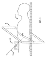
図2は、対象者の身体15に取り付けられる自動化挿入デバイス100を概略的に示す。一部の実装では、対象者の身体に挿入デバイスを取り付ける前に、ユーザは、関心領域の初期スキャン(「スキャン」の用語は本開示を通じて1つ以上のフレームのことを言う場合が有る)において侵入の初期点、標的及び侵入点から標的への任意の可能な途中の障害物に印を付ける。次に、システムソフトウェアは、最適な針軌道を計算してもよく、これは、例えば、患者の組織に最小側圧を与える軌道であってもよい。一部の実装では、最適軌道の計算は、侵入点における針の侵入角度の決定を含んでもよい。他の実装では、ユーザは、軌道計算の前に侵入角度を入力しなくてはならない。針軌道を計画するための方法は、例えば、Shochatの共有国際特許出願第PCT/IL2015/050230号、“Dynamic Planning Method for Needle Insertion”に開示されており、参照によりその全体が本明細書に組み込まれる。
FIG. 2 schematically shows an
針挿入手順の間、針の実際の位置を検証し、必要に応じて、それに従って軌道を調節するために複数のスキャンが要求されてもよい。患者及び医療従事者の放射線被曝を最小化するために、スキャン容積4は、典型的には、できるだけ小さくなるように選択される。従って、場合によっては、例えば、標的8に到達するための最適軌道がCTシステムの軸方向フレーム(即ち、患者の身体の長軸に対して垂直な軸平面に生成されるフレーム)に対して僅かな/大きな挿入角度、例えば、25−30度よりも大きな角度を必要とする場合に、挿入デバイス100は、図2に示されるように全体がスキャン容積4の外側に位置付けられてもよい。典型的には、レジストレーションマーカは1つ以上の挿入デバイスのコンポーネントに結合されるので、デバイスがスキャン容積の外側に位置付けられる場合、先行技術の方法を用いて、画像空間に対するデバイス100の場所を位置合わせすることはできない。しかし、これは、針挿入手順の間に正確な移動/操縦指示を挿入デバイス100に与えるために必要である。
During the needle insertion procedure, multiple scans may be required to verify the actual position of the needle and, if necessary, adjust the trajectory accordingly. To minimize radiation exposure to patients and healthcare professionals, the scan volume 4 is typically chosen to be as small as possible. Thus, in some cases, for example, the optimal trajectory to reach target 8 is small relative to the axial frame of the CT system (ie, the frame generated in the axial plane perpendicular to the long axis of the patient's body). If a large insertion angle, eg, an angle greater than 25-30 degrees, is required, the
図3Aは、結合の前の挿入デバイス100及び取り付けパッド30を概略的に示す。挿入デバイス100は取り外し可能に取り付けパッド30に結合されてもよく、それにより挿入デバイス100及び取り付けパッド30は2つの別個のユニットであり、挿入デバイス100は取り付けパッド30に結合され、次にそれから取り外され得る。代替的に、挿入デバイス100及び取り付けパッド30は、互いに強固に結合されてもよく、又は単一のユニットとして更に構成されてもよい。取り付けパッド30は、身体装着デバイスの場合、挿入デバイス100が接続されるベースプレート310を含んでもよく、取り付けパッド30を、ひいては挿入デバイス100を対象者の身体に固定する1つ以上のストラップ又はベルト312を更に含んでもよい。ベースプレート310及び1つ以上のストラップ312は、取り付けパッド30の一体部分であってもよく、取り付けパッド30に取り外し可能に結合される別個のコンポーネントであってもよい。更に、1つ以上のストラップ312は、取り付けパッド30又はベースプレート310の何れかに強固に又は取り外し可能に結合されてもよい。ベースプレート310は、図3Aに示されるように”U”形状であってもよく、又は挿入デバイス100及び/又は取り付けパッド30の設計に依存して、任意の他の適切な形状を含んでもよい。
FIG. 3A schematically shows the
一部の実装によれば、取り付けパッド30は、コーヒー豆、稲、砂、プラスチックビーズ等の自然又は人口の顆粒322が少なくとも部分的に充填された柔軟な嚢/クッションとして構成されてもよい。取り付けパッド30は真空バルブ324を更に含んでもよく、それにより真空がバルブ324を介して取り付けパッド30に加えられると、顆粒322が互いに対して押し付けられて、取り付けパッド30は硬化する。真空が加えられた後で、取り付けパッド30の形状は、真空が除去されて空気がパッドに戻ることができるようになるまで変形され得ない。取り付けパッドを硬化するための真空の使用は単なる例示に過ぎず、取り付けパッドは加熱又は冷却等の任意の他の適切な方法を使用して硬化させられてもよい。
According to some implementations, the mounting
取り付けパッド30は、1つ以上のレジストレーション部材328(例えば、基準マーカ)を更に含み、これは、以下で詳細に説明されるように、挿入デバイス100の位置/移動を決定するために調節可能レジストレーションフレームを互いに形成する。
The mounting
一部の実装では、レジストレーション部材328は、顆粒322と共に、取り付けパッド30の内側に設けられてもよく、それによりパッドがその屈曲性/成形可能形態に有る場合に、例えば、真空を加える前に、レジストレーション部材328は取り付けパッド30の内側又は取り付けパッド30の限定部分の内側を動き回ることができる。他の実装では、レジストレーション部材328は、取り付けパッドのカバーに、カバーの一体部分として結合され、又は、レジストレーション部材328が外部環境に面するようにカバーの外面に、又はレジストレーション部材328がパッド30内で顆粒322に面するようにその内面に、取り外し可能に結合されてもよい。レジストレーション部材328が取り付けパッドのカバーに結合される場合、パッドが屈曲性の形態である場合、レジストレーション部材328はカバーと共にのみ動くことができる。真空が取り付けパッド30に加えられ、且つ取り付けパッド30がより固化された/剛性の形態に変換されると、レジストレーション部材328は、互いに対して、取り付けパッドのカバー及び顆粒に対して、並びに挿入デバイス100に対してもはや動くことができない。更に、真空が加えられると、パッド30の底部が対象者の身体15の形状及び輪郭に一致してもよく、それにより挿入デバイス100に安定性が提供され且つ対象者への不快感が最小化される。一部の実装では、真空が加えられると、対象者の身体の形状を受け入れる取り付けパッド及び固定されたストラップ312の組み合せは、取り付けパッド全体及びそれに結合された挿入デバイスが、挿入処置の間に対象者の身体に対して動くことを防ぎ得る。一部の実装では、取り付けパッド30は、真空の印加に応じてパッド30の一部のみが対象者の身体15の形状に一致するように構成されてもよい。例えば、ベースプレート310を含む部分のみが対象者の身体15の形状に一致してもよく、例えば、取り付けパッド30が取り付けられる表面から僅かに持ち上げられて保持されるように構成される剛性の底部を有することにより、レジストレーション部材328を含む部分が対象者の身体の上に僅かに浮かんだままになってもよく、それにより例えば、呼吸による動きが取り付けパッド30のその部分の動きをもたらさないであろう。これは、パッドのベースプレート部が配置されていない身体のエリアが呼吸により影響を受けない(即ち、動かない)場合に最重要であるが、例えば、レジストレーション部材328を含むパッドの部分が配置されている身体のエリアが呼吸により影響を受け、それにより、挿入デバイス100の動きが実際に無い場合に、検出されたマーカの動きが挿入デバイス100の対応する動きとして誤って決定されるかもしれない。
In some implementations, the
レジストレーション部材328は、撮像システム(例えば、X線、CT、MRI)を使用して撮影された画像に検出され得る(複数の)材料から少なくとも部分的に製造され、カバー及び顆粒等の全ての他の取り付けパッド要素から明確に区別される。更に、レジストレーション部材の(複数の)材料は、撮像アーチファクトを引き起こさないように選択されるべきである。CTシステムが利用される場合、例えば、このような材料は、炭素、アルミニウム、ポリエーテル・エーテル・ケトン(PEEK)等であってもよい。挿入デバイス100自体に配置されるマーカに加えて(図示せず)、レジストレーション部材328が設けられることが理解されるべきである。
The
取り付けパッド30は、様々な形状及びサイズで提供されてもよい。それは、図3B及び3Cに示されるように、U字状形状のような対称性を有してもよく、或いはそれは、図3Dに示されるように、パッドの片側から外側に延びるスリーブ状部分のような非対称性を有してもよい。取り付けパッド30は、1つ以上のストラップ312又は任意の他の適切な取り付け手段を使用して対象者の身体に取り付けられるクッション又は枕として構成されてもよく、或いはそれは対象者によって装着されるように構成され、且つ指定されたシャツ、ベスト、ハーネス等として構成されてもよい。針110が患者の身体にアクセスできるように、取り付けパッド30は、図3A、3C及び3Dに示されるように、開口326を含んでもよく、或いはそれは、例えば、図3Bに示されるように、「開放端」を有するように構成されてもよい。
The mounting
一部の実装では、取り付けパッド30は、互いに取り外し可能に結合され得る2つ(以上)の別個のパッド、即ち、配置パッド及びレジストレーションパッド(図示せず)を含んでもよい。このような場合、レジストレーションパッドは、レジストレーション部材328を含み、それは、挿入デバイス100の位置及び方向を決定するために使用され、配置パッドは、例えば、挿入デバイスが身体の湾曲エリア及び/又は挿入デバイス100と身体との間の限定的な接触のみを許容するエリアに配置されることが意図される場合に、対象者の身体への挿入デバイス100の安定した配置を可能にするために使用されてもよい。配置パッドは、挿入デバイス100を身体に直接的に配置することによる対象者の不快感又は痛みを最小化するように、挿入デバイス100の下に詰め物を提供するために更に使用されてもよい。配置パッドは、ベースプレートが利用される場合にベースプレート310を含んでもよい。レジストレーションパッド無しで使用される場合、配置パッドは、柔軟状態のままにされてもよく、このような場合、配置パッドはレジストレーションに使用されないので、それを剛性状態に変換する必要はない。別個の場合、配置パッドの使用は選択的であり、医師は配置パッドを使用しないこと及び挿入デバイス又はベースプレート310を対象者の身体に直接的に配置しないことを選択してもよい。このような場合、レジストレーションパッドは、ベースプレート310に、又は直接的に挿入デバイス100に接続可能であってもよい。更に、別個の場合、レジストレーションパッドの使用も選択的であってもよい。即ち、最適軌道に従って、挿入デバイスの位置、侵入点及び標的が、少なくとも挿入デバイスの一部が必ず任意の必要とされるスキャンにおけるスキャンエリア内に有るようにされている場合、レジストレーションパッドは必要とされなくてもよい。2つのパッドが一緒に使用される場合、一旦真空が加えられると、2つのパッド間に相対運動が無いように、これらは互いに結合され、これらは事実上単一のパッドを一緒に形成する。
In some implementations, the mounting
次に図4A−8が参照され、これらは本開示のシステム及び方法の例示的な実装を示す。この実装では、取り付けパッド40のレジストレーション部材は、多関節ロッドアセンブリ428として構成され、各多関節ロッドアセンブリは1つ以上のロッド430から作られ、これはジョイント432によって接続されてもよく、現在の画像空間に対する挿入デバイスの位置及び方向、即ち、現在の画像の座標系に関するその位置及び方向が、以下で詳細に説明されるように、現在の画像空間に対するロッドの変形(即ち、位置及び方向)の計算、及び挿入デバイスに対するロッドの以前に計算された(且つ固定された)変形に基づいて決定される。
4A-8 are then referred to, which show exemplary implementations of the systems and methods of the present disclosure. In this implementation, the registration member of the mounting
図4Aは、取り付けパッド40に真空を加える前の、顆粒422が充填された屈曲性嚢/クッション、及びそれに結合される挿入デバイス100として構成される例示的な取り付けパッド40の斜視図を示す。図示されていないが、例えば、(図4Aには示されていない)ストラップ又はベルト等を使用することにより、取り付けパッド40が対象者の身体に固定された後でのみ、真空の印加が実行されることが理解されるべきである。挿入デバイス100は、対象者の身体への取り付けパッド40の配置の前後の何れかで取り付けパッド40に結合されてもよい。
FIG. 4A shows a perspective view of an
図4Aに示された実装では、レジストレーションフレームは、3つの多関節ロッドアセンブリ428から成り、各多関節ロッドアセンブリは4つのロッド430及び5つのジョイント432を有する。レジストレーションフレームは、上記の数の多関節ロッドアセンブリ、ロッド及び/又はジョイントに限定されず、レジストレーション処置(以下を参照)のために要求されるロッドセットの一意の識別が使用可能である限り、任意の数のジョイントと共に任意の数のロッドを有する任意の数の多関節ロッドアセンブリから成ってもよいことが理解されるべきである。ジョイント432は、好ましくは、各ロッドに少なくとも3つの自由度(DOF)、即ち、上/下、左/右及び回転を可能にするべきである。ジョイント432は、例えば、球状ジョイントとして構成されてもよい。バルブ424を介して取り付けパッド40に真空を加える前に、ロッド430は互いに対して自由に動くことができ、そのため取り付けパッド40の動きはパッド内の多関節ロッドアセンブリ428の多くの異なる空間的配置をもたらし得る。
In the implementation shown in FIG. 4A, the registration frame consists of three articulated
図4Bに示されるように、取り付けパッド40に真空が加えられると、顆粒422は互いに対して及び多関節ロッドアセンブリ428に対して押し付けられ、そのため各多関節ロッドアセンブリ428は1つの構成に固定されることになり、互いに対する多関節ロッドアセンブリ428の動き及び/又は同じアセンブリ428の他のロッドに対する各多関節ロッドアセンブリ428のロッド430の動きはもはや無くなる。更に、真空が加えられると、挿入デバイス100に対する多関節ロッドアセンブリ428の動きも無くなる。従って、レジストレーションフレーム及び挿入デバイス100は、レジストレーションフレームの動きが必ず挿入デバイスの同一の動きを示すように、1つの固形物と見なされてもよい。従って、以下で詳細に記載されるように、画像空間に対するレジストレーションフレーム(又はその一部)の計算された位置及び方向に基づいて、たとえ挿入デバイスがスキャン容積の外側に配置されていても、画像空間に対する挿入デバイスの位置及び方向は、挿入処置の間の任意の点で計算され得る。
As shown in FIG. 4B, when vacuum is applied to the mounting
図4Bには示されていないが、取り付けパッド40に真空が加えられると、パッド40の底部は、全体的に又は部分的に、対象者の身体の形状に一致してもよいことが理解され得る。
Although not shown in FIG. 4B, it is understood that when vacuum is applied to the mounting
取り付けパッド40が対象者の身体に固定され、挿入デバイス100が取り付けパッド40に結合され、且つ真空が取り付けパッド40に加えられた後で、臨床医は、「準備段階」とも呼ばれるレジストレーション処置の初期段階を開始し得る。
After the mounting
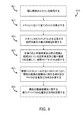
図5は、多関節ロッドアセンブリを使用するレジストレーション処置の例示的な初期/準備段階で実行されるステップのフローチャート500を示す。
FIG. 5 shows a
ステップ501では、全体のレジストレーションフレーム及び挿入デバイスの初期スキャンが得られる。初期スキャンは、レジストレーションフレーム全体(全ての多関節ロッドアセンブリが互いにレジストレーションフレームを構成する)及び挿入デバイスを含む。初期スキャンの間に撮影された画像の数及び画像間の間隔は、ユーザによって決定されてもよく、又はシステムソフトウェアによって決定されてもよい。画像は、通信モジュールを使用して(例えば、ローカルエリアネットワーク上で(複数の)DICOMファイルを転送して)、又はCD、DVD、USB携帯ドライブ等の外部記憶装置を使用して、例えば、直接的に(即ち組み込みシステム等により)、任意の適用可能な方法で撮像システムから取得されてもよい。一部の実装では、スキャンは、ユーザによって手動で開始されてもよい。他の実装では、スキャンは、挿入システムのソフトウェアによって自動的に開始されてもよい。
In
ステップ502では、挿入デバイスの基準マーカは、画像処理技術を使用して検出される。挿入デバイスに取り付けられるこうしたマーカは、サイズ及び形状等の既知のパラメータを有する。
In
ステップ503では、初期画像空間の座標系に関する挿入デバイスの位置及び方向が計算される。
In
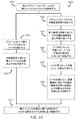
ステップ504では、画像処理技術を使用して初期スキャンにおける全てのロッドが検出される。先に述べたように、レジストレーションフレームを構成するロッドは、撮像システム(例えば、X線、CT、MRI)によって撮影された画像において識別され得る(複数の)材料から少なくとも部分的に製造される。
In
ステップ505では、レジストレーションフレームの全ての2つのロッドの間の最小距離及び空間角度が計算され且つ記憶される。このデータは、各ロッドペアを定義する。一部の実装では、上記の計算は、レジストレーションフレームにおいて、ありとあらゆる2つのロッドの組み合わせに対して行われる。他の実装では、上記の計算は、フィルタリング/スクリーニング処理が実行された後で、同じスキャンに現れることが不可能であるか又は非常に可能性が低いと見なされるロッドペアに対しては行われない。例えば、このようなペアは、同じ多関節ロッドアセンブリに属するが隣接していない2つのロッド(即ち、ジョイントによって接続されていないロッド)のペアであってもよい。
In
2つのロッドが平行しておらず、それらが又はそれらの延長線が互いに交差しない場合、2つのロッド間の3次元空間における最小距離は、両方のロッドに一意に同時に垂直であるセグメントの長さである。2つのロッド又はそれらの延長線が交差する場合、それらの間の最小距離はゼロである。全ての2つのロッド間の空間角度はランダム且つ特異的である。従って、最小距離及び空間角度が分かっている場合、任意のロッドペアは後でトレースされ得る。 If the two rods are not parallel and they or their extensions do not intersect each other, the minimum distance in three-dimensional space between the two rods is the length of the segment that is uniquely perpendicular to both rods at the same time. Is. If two rods or their extensions intersect, the minimum distance between them is zero. The spatial angle between all two rods is random and specific. Therefore, any rod pair can be traced later if the minimum distance and spatial angle are known.
ステップ506では、ステップ505で最小距離及び空間角度が計算され且つ記憶された全ての2つのロッドに対して、最小距離点(以後、”MDP”とも言う)が計算され且つ記憶される。MDPは、2つのロッドが互いに最も近づく2つのロッドにおける特異点である。即ち、これらは、2つのロッドが平行ではなく、互いに交差しない場合に、両方のロッドに一意に同時に垂直であるセグメントによって連結される2つの点であり、その長さは2つのロッド間の最小距離である。MDPは、ロッド自体にあってもよく、又はロッドの無限延長線上(即ち、ロッドの範囲外)にあってもよく、これらはこうした線の制限サブセットである。2つのロッド又はこれらの無限延長線が交差する場合、MDPは結合される。
In
それがペアリングされる他のロッドの数に依存して、各ロッドは複数のMDPを有してもよい。例えば、レジストレーションフレームが全部で15のロッドから作られるように、各々が5つのロッドを有する3つの多関節ロッドアセンブリからレジストレーションフレームが構成される場合、各ロッドは、その多関節ロッドアセンブリに属する4つのロッドを含む他の14のロッドの各々とペアリングされ得るので、14のMDPを有してもよい。 Each rod may have multiple MDPs, depending on the number of other rods it is paired with. For example, if the registration frame is composed of three articulated rod assemblies, each with five rods, such that the registration frame is made up of a total of 15 rods, then each rod will be in that articulated rod assembly. It may have 14 MDPs as it can be paired with each of the other 14 rods, including the 4 rods to which it belongs.
また、各ロッドペアに対してステップ506で計算され且つ記憶されるのは、初期画像空間の座標系に関するロッドペア座標系(以後、”RPCS”とも呼ばれる)であり、即ち、画像空間の座標系に対するRPCSの位置及び方向である。図6に示されるように、RPCSの原点はロッドのMDPに有り、そのXYZベクトルはロッド又はその延長線、結合されたロッドのMDPへのベクトル、及び最初の2つのベクトルの外積によって定義される。
Further, what is calculated and stored for each rod pair in
一部の実装では、レジストレーションフレームがnのロッドを含む場合、理論上は、各ロッドに対して、n−1のMDP及びRPCSが見つかって記憶されるように、各ロッドは残りのn−1のロッドの各々とペアリングされてもよい。例えば、各々が5つのロッドを有する3つの多関節ロッドアセンブリからレジストレーションフレームが構成される場合、各ロッドは14のMDP及び14のRPCSを有してもよい。他の実装では、ペアリングには、各ロッドに対して計算されたn−1のMDP及びRPCSよりも少なくなる所定の限界が有ってもよい。例えば、その特定のロッドと同じ多関節ロッドアセンブリの一部であるロッドを除外して、各ロッドが参照フレームにおける全ての他のロッドとペアリングされ得るように、フィルタリング処理が実行されてもよい。更に、一部の実装では、図6に示されるように、1つのRPCSのみが各ロッドペアに対して計算される。 In some implementations, if the registration frame contains n rods, then for each rod each rod will theoretically have the remaining n- so that n-1 MDPs and RPCSs will be found and stored. It may be paired with each of the rods of 1. For example, if the registration frame is constructed from three articulated rod assemblies, each with five rods, each rod may have 14 MDPs and 14 RPCSs. In other implementations, pairing may have a predetermined limit that is less than the calculated n-1 MDP and RPCS for each rod. For example, filtering may be performed so that each rod can be paired with all other rods in the reference frame, excluding rods that are part of the same articulated rod assembly as that particular rod. .. Moreover, in some implementations, only one RPCS is calculated for each rod pair, as shown in FIG.
ステップ507では、初期画像空間の座標系に関してRPCSの及び挿入デバイスの位置及び方向を計算した後で、それぞれステップ503及び506では、上記の2つの計算に基づいて、挿入デバイスの座標系に関するRPCSの位置及び方向が計算される。
In
取り付けパッドに真空が加えられた後ではレジストレーションフレームと挿入デバイスとの間の相対運動が無いので、挿入デバイスの座標系に関するRPCSの位置及び方向は、真空が除去されるまで変化せずに維持されるであろう。以下の図8に詳細に記載されるように、特定の新しい画像の座標系に関するスキャン容積に含まれるRPCSの位置及び方向の計算、及び挿入デバイスの座標系に関するRPCSの既知の位置及び方向に基づいて、挿入処置を通じて得られる各画像の座標系に関する挿入デバイスの位置及び方向が計算され得るので、これは挿入デバイスがスキャンされた容積の外に配置されることを可能にする。 Since there is no relative movement between the registration frame and the insertion device after the mounting pad is evacuated, the position and orientation of the RPCS with respect to the insertion device's coordinate system remains unchanged until the vacuum is removed. Will be done. Based on the calculation of the position and orientation of the RPCS contained in the scan volume for the coordinate system of the particular new image, and the known position and orientation of the RPCS for the coordinate system of the insertion device, as detailed in FIG. 8 below. This allows the insertion device to be placed outside the scanned volume, as the position and orientation of the insertion device with respect to the coordinate system of each image obtained through the insertion procedure can be calculated.
図6は、挿入デバイスの座標系60及び2つの例示的なロッド630A及び630Bを示す。2つのロッド間の最小距離633も示されており、即ち、図6に示されるように、両方のロッドに又はそれらの延長線に垂直なセグメントの長さである。互いに対するロッドのMDP635A及び635B、及びロッドペア630A、630Bのロッドペア座標系63が更に示されている。この例では、問題のロッドペアは(630A、630B)であるので、ロッド630AのMDP635AにRPCS63の原点が位置付けられている。ロッドペア(630B、630A)のRPCSの原点は、ロッド630BのMDP635Bに位置付けられたであろう。RPCS63のX’Y’Z’ベクトルはロッド630A(又はその無限延長線)、結合されたロッド630BのMDP635Bへのベクトル、及び最初の2つのベクトルの外積によって定義される。
FIG. 6 shows the coordinate
図7Aは、取り付けパッドに真空が加えられた後の、図4A−4Bの例示的な取り付けパッド40及びそれに結合された挿入デバイス100の上面図を示す。真空が加えられると、別のロッド又はロッドアセンブリに対する任意のロッド又はロッドアセンブリの動き、及び挿入デバイス100に対する任意のロッド又はロッドアセンブリの動きが無くなる。図7Aに示された実施形態におけるレジストレーションフレームは、3つの多関節ロッドアセンブリ428A、428B及び428Cから成り、各々が4つのロッド及び5つのジョイントを有している。針挿入手順を開始する前に、その中にレジストレーションフレームを有し、そこに挿入デバイス100が結合されている取り付けパッド40全体を含む初期スキャンが行われる。次に、図5に関して先に詳細に説明されたのと同じやり方で、空間角度、MDP及びRPCSが計算され且つ記憶される。
FIG. 7A shows a top view of the
挿入処置の間に、対象者及び医療従事者への放射線被曝を最小化するために容積が限定されるリアルタイムスキャンが行われる。スキャンの間に撮影されるフレームの数及びフレーム間の間隔は、ユーザ(例えば、医師)によって決定されてもよく、又はシステム要件であってもよい。 During the insertion procedure, a volume-limited real-time scan is performed to minimize radiation exposure to subjects and health care workers. The number of frames taken during the scan and the spacing between the frames may be determined by the user (eg, a physician) or may be a system requirement.
図7Aに示されるように、スキャン容積700は横軸であってもよく、又は斜めであるか若しくは取り付けパッド40の軸に対する任意の他の方向を有してもよい。例示的なスキャン容積700は、3つの多関節ロッドアセンブリ428A、428B及び428Cの各々の1つのロッドの部分、即ち、ロッド430A、430B及び430C、並びに3つの多関節ロッドアセンブリ428A、428B及び428Cの各々の1つのジョイントの部分、即ち、ジョイント432A、432B及び432C、を含む。しかしながら、スキャン容積はレジストレーションフレームの全ての多関節ロッドアセンブリ428A、428B及び428Cのロッドを必ずしも含まないことが理解されるべきである。更に、スキャン容積700は、同じ多関節ロッドアセンブリの複数のロッドを含んでもよい。
As shown in FIG. 7A, the
図7Bは、スキャンされた容積700の例示的な画像フレーム710を示す。この例示的な画像フレーム710は、図7Aにおける軸BB’に沿って撮られた、患者の身体15の及び患者の身体に配置された取り付けパッド40の横断面図を示す。画像フレーム710には、レジストレーションフレームの1つのロッド430B及び2つのジョイント432A及び432Cの断面図が含まれている。
FIG. 7B shows an
図8は、図4A−4Bに示された調節可能レジストレーションフレームを使用して、挿入処置の間の任意の瞬間に画像空間に対する挿入デバイス100の位置及び方向を決定するための例示的な方法において実行されるステップのフローチャート800を示す。
FIG. 8 is an exemplary method for determining the position and orientation of the
ステップ801では、図7A−7Bに示されるように、レジストレーションフレームの一部を含む関心領域のスキャンが得られる。スキャンされる関心領域は、例えば、標的(例えば、腫瘍)及び/又は針先を包含するように決定されてもよい。 In step 801 a scan of the region of interest containing a portion of the registration frame is obtained, as shown in FIGS. 7A-7B. The area of interest to be scanned may be determined to include, for example, a target (eg, a tumor) and / or a needle tip.
ステップ802では、画像処理技術を使用してスキャンに含まれる全てのロッドが検出される。特定のスキャンに含まれる全てのロッドは、「ロッドセット」と呼ばれてもよい。
In
ステップ803では、スキャンに含まれる全ての2つのロッド、即ち、ロッドセットにおける全てのロッドペアの間の最小距離及び空間角度が計算される。ロッドセットが2つより多くのロッドを含む場合、ロッドセットを一意に定義するために複数の2つのロッドのサブセットのみに関して最小距離及び空間角度を計算すれば十分で有り得ることが理解されるべきである。例えば、ロッドセットが3つのロッド、即ち、ロッドa、ロッドb及びロッドcを含む場合、例えば、ロッドbとロッドcとの間の最小距離及び空間角度はロッドaとロッドbとの間及びロッドaとロッドcとの間の最小距離及び空間角度によって決定されるので、ロッドaとロッドbとの間及びロッドaとロッドcとの間の最小距離及び空間角度を計算すれば十分であってもよい。
In
2つのロッドの間の最小距離及び空間角度を決定するために、スキャン容積内で撮影された少なくとも2つの画像フレームを必要とすることが理解され得る。 It can be understood that at least two image frames taken within the scan volume are required to determine the minimum distance and spatial angle between the two rods.
ステップ804では、計算された最小距離及び空間角度は、レジストレーション処置(図5のステップ505を参照)の準備段階の間に計算され且つ記憶された最小距離及び空間角度と比較され、参照ロッドセットが決定される。即ち、それらの全体又は部分においてどのロッドがスキャンに現れるかが識別され、こうしたロッドは、現在の画像空間の座標系に対するレジストレーションフレームの位置及び方向を決定するための参照セットとして機能するであろう。真空が維持される限りロッド間の最小距離及び空間角度は変化しないので、最小距離及び空間角度は、ロッドをトレースして、どのロッドがスキャンに現れるかを決定するために使用され得る。
In
最も良く一致するロッドセットが参照ロッドセットとして決定されるまで、このステップは複数の反復を含んでもよいことが理解され得る。スキャンにおけるノイズのために、記憶された最小距離及び空間角度と比較される場合に、計算された最小距離及び空間角度は、複数の可能な参照ロッドペアを生成してもよい。しかしながら、一部のロッドペアの組み合わせ(即ち、2つ以上のロッドペアを合わせて)は、地理的に不可能であってもよい。即ち、それらがスキャン容積に一緒に含まれることが不可能であるように、それらはレジストレーションフレーム上に位置付けられてもよい。従って、参照ロッドセットは、複数の反復後に、計算された値、即ち、最小距離及び空間角度、並びに地理的論理の両方に関して最良一致セットであると決定されるロッドセットであってもよい。 It can be understood that this step may include multiple iterations until the best matching rod set is determined as the reference rod set. Due to noise in the scan, the calculated minimum distance and spatial angle may generate multiple possible reference rod pairs when compared to the stored minimum distance and spatial angle. However, some rod pair combinations (ie, two or more rod pairs combined) may not be geographically possible. That is, they may be positioned on the registration frame so that they cannot be included together in the scan volume. Thus, the reference rod set may be the rod set that is determined after multiple iterations to be the best match set for both the calculated values, i.e. the minimum distance and spatial angle, as well as the geographic logic.
上記に照らして、参照ロッドセットの効果的な識別を達成するために、レジストレーションフレームは、スキャン容積がどのように選択されるかに関わらず、好ましくは、少なくとも3つのロッドがスキャン容積に含まれるように設計されるべきであること、及び/又はスキャン容積は、少なくとも3つのロッドがそれに含まれるように選択されるべきであることが更に理解され得る。 In light of the above, in order to achieve effective identification of the reference rod set, the registration frame preferably includes at least three rods in the scan volume, regardless of how the scan volume is selected. It can be further understood that it should be designed to be and / or the scan volume should be selected so that at least three rods are included in it.
ステップ805では、参照ロッドセットにおける2つのロッドごとに、現在の画像の座標系に関するMDP及び(複数の)RPCSの位置及び方向が計算される。
In
ステップ806では、現在の画像空間の座標系に関する挿入デバイスの位置及び方向が計算される。取り付けパッドに真空が加えられた後で、真空が除去されない限り、レジストレーションフレームと挿入デバイスとの間の相対運動が無いので、レジストレーション処置(図5を参照)の準備段階で計算された挿入デバイスの座標系に関するRPCSの位置及び方向は、変化せずに維持されるであろう。従って、ステップ805で計算されたように、現在の画像空間の座標系に関する挿入デバイスの位置及び方向は、挿入デバイスの座標系に関するスキャン容積に含まれるRPCS(即ち、参照ロッドセットのRPCS)の既知の位置及び方向、及び現在の画像空間の座標系に関するこうしたRPCSの位置及び方向を使用して計算され得る。
In
現在の画像の座標系に関する位置及び方向は各RPCSに対して別々にステップ805で計算されるので、一部の実装では、現在の画像座標系に関する挿入デバイスの位置及び方向を計算するために、ステップ805で計算されたRPCSの全ての位置及び方向は、(例えば、最小二乗法を使用して)最小総合誤差を生み出す最適変換を決定するために互いに結合される。他の実装では、現在の画像座標系に関する挿入デバイスの位置及び方向は、別々に各RPCSの位置及び方向に基づいて計算され、各RPCSによって計算された挿入デバイスの位置及び方向は、現在の画像の座標系に関して挿入デバイスの最適変換を決定するために結合される。
Since the position and orientation of the current image with respect to the coordinate system is calculated separately for each RPCS in
現在の画像空間の座標系に関する挿入デバイスの位置及び方向が決定されると、挿入システムのオペレータは、標的に向かって医療器具(例えば、針)を操縦するために正確な指示を挿入デバイスに与えることができる。 Once the position and orientation of the insertion device with respect to the coordinate system of the current image space has been determined, the operator of the insertion system gives the insertion device accurate instructions to steer the medical device (eg, needle) towards the target. be able to.
次に図9A−12が参照され、これらは本開示のシステム及び方法の別の例示的な実装を示す。この実装では、取り付けパッドの1つ以上のレジストレーション部材が、ストリップ等の半屈曲性要素として構成され、現在の画像空間に対する挿入デバイスの位置が、以下で詳細に説明されるように、現在の画像空間に対する半屈曲性ストリップの位置及び方向並びに挿入デバイスに対する半屈曲性ストリップの以前に計算された(且つ固定された)位置及び方向に基づいて決定される。 9A-12 are then referred to, which show another exemplary implementation of the systems and methods of the present disclosure. In this implementation, one or more resisting members of the mounting pad are configured as semi-flexible elements such as strips, and the position of the insertion device with respect to the current image space is current, as described in detail below. Determined based on the position and orientation of the semi-flexible strip with respect to image space and the previously calculated (and fixed) position and orientation of the semi-flexible strip with respect to the insertion device.
図9Aは、取り付けパッド90に真空を加える前の、顆粒922が充填された屈曲性嚢/クッション、及びそれに結合される挿入デバイス100として構成される例示的な取り付けパッド90の斜視図を示す。図示されていないが、例えば、(図9Aには示されていない)ストラップを使用して、取り付けパッド90が対象者の身体に配置され且つそこに固定された後でのみ、真空の印加が実行されることが理解されるべきである。挿入デバイス100は、対象者の身体への取り付けパッド90の配置の前後の何れかで取り付けパッド90に結合されてもよい。この実装では、レジストレーションフレームは、4つの半屈曲性ストリップ928から成る。4つのストリップの使用は単なる一例であり、レジストレーション処置(以下を参照)に必要とされる各スキャンに含まれる半屈曲性ストリップの一意の識別が有効である限り、レジストレーションフレームは、任意の数の半屈曲性ストリップを含んでもよいことが理解されるべきである。半屈曲性ストリップ928は、好ましくは、一方向に屈曲性が有り、第1の方向とは垂直の方向に剛性であり、例えば、ケーブルタイ/タイラップとして構成される調節可能レジストレーションフレームは、図9Aに示されるように、単一の頂点を起点とする複数の半屈曲性ストリップ928を含んでもよい。しかしながら、それ以外の場合、半屈曲性ストリップ928は、互いから完全に離れて配置されてもよい。ストリップ928は、カバーの一体部分として取り付けパッドのカバーに結合されるか、又はそこに取り外し可能に結合されてもよい。このような場合、ストリップ928は、カバーの外面(即ち、外部環境に面している)又はその内面(即ち、顆粒922に面している)の何れかに結合されてもよい。ストリップ928が取り付けパッドのカバーに結合される場合、パッド90が屈曲性成形可能形態に有る場合、ストリップ928はそのカバーと共にのみ動くことができる。図9Bに示されるように、取り付けパッド90に真空が加えられ、それが固化/剛性形態に変形すると、ストリップ928は、もはや動くことができず、固定されることになる。更に、挿入デバイス100に対するストリップ928の動きも無くなる。図9Bには示されていないが、取り付けパッド90に真空が加えられると、パッド90の底部は、全体的に又は部分的に、対象者の身体の形状に一致してもよいことが理解され得る。
FIG. 9A shows a perspective view of an
取り付けパッドが対象者の身体に固定され、挿入デバイス100が取り付けパッド90に結合され、且つ真空が取り付けパッド90に加えられた後で、臨床医は、レジストレーション処置の初期/準備段階を開始し得る。
After the mounting pad is secured to the subject's body, the
図10は、図9A−9Bに示された半屈曲性ストリップ/要素を使用して、レジストレーション処置の例示的な初期/準備段階で実行されるステップのフローチャート1000を示す。
FIG. 10 shows a
ステップ1001では、全体のレジストレーションフレーム及び挿入デバイスの初期スキャンが得られる。初期スキャンの間に撮影された画像の数及び画像間の間隔は、ユーザによって決定されてもよく、又はシステムソフトウェアによって決定されてもよい。画像は、通信モジュールを使用して(例えば、ローカルエリアネットワーク上で(複数の)DICOMファイルを転送して)、又はCD、DVD、USB携帯ドライブ等の外部記憶装置を使用して、例えば、直接的に(即ち組み込みシステム等により)、任意の適用可能な方法で撮像システムから取得されてもよい。一部の実装では、スキャンは、ユーザによって手動で開始されてもよい。他の実装では、スキャンは、挿入システムのソフトウェアによって自動的に開始されてもよい。
In
ステップ1002では、挿入デバイスに結合される全てのマーカは、画像処理技術を使用して検出される。
In
ステップ1003では、初期画像空間の座標系に関する挿入デバイスの位置及び方向が計算される。
In
ステップ1004では、画像処理技術を使用して初期スキャンにおける全ての半屈曲性要素(又はストリップ)が検出される。
In
ステップ1005では、各半屈曲性要素に対して、以下に定義される要素を含む平面が見つけられる。一次元ストリングとして構成されることとは対照的に半屈曲性要素は幅を有し得るので、半屈曲性要素を含む平面は、例えば、その縦中心線、即ち、要素の長さに沿って要素の幅の中心点を接続する線を含む平面のことを言ってもよい。半屈曲性要素が一方向にのみ屈曲性を有し且つ第1の方向とは垂直な方向には剛性を有する(即ち、それらは横向きに曲げることができない)ので、各半屈曲性要素に対してこのような1つの平面のみが存在する。全ての要素に対して使用される平面に一貫性が有る限り、上記の平面に平行な任意の平面がその代わりに見つけられ得ることが理解され得る。
In
ステップ1006では、ステップ1005に見つけられた2つの平面ごとに、2つの平面の間の角度が計算され且つ記憶される。各半屈曲性要素に対して、その要素の縦中心線を含む1つの平面のみが存在するので、2つの平面の間の角度は一意であり、そのため後続のスキャンに現れる半屈曲性要素をトレースするために使用され得る。
In
どの半屈曲性要素が特定のスキャンに含まれるかを識別するために平面間の角度を使用することは、即ち、記憶されている角度と計算された角度を比較することによって、以下に記載されるように、どのように半屈曲性要素が識別され得るかの単なる一例に過ぎないことが理解され得る。複数又は全ての要素に識別マーク(例えば、小突起、剛毛等)を付加すること、異なる特徴(例えば、幅)又は材料を有する要素を使用すること、異なる平面の交線の間の角度を計算し且つ比較すること(以下を参照)等、任意の他の適切な方法を使用して半屈曲性要素は識別され得る。 Using the angle between planes to identify which semi-flexible element is included in a particular scan is described below by comparing the stored angle with the calculated angle. As such, it can be understood that it is merely an example of how semi-flexible elements can be identified. Add identification marks (eg, small protrusions, bristles, etc.) to multiple or all elements, use elements with different features (eg, width) or materials, calculate the angle between lines of intersection in different planes Semi-flexible elements can be identified using any other suitable method, such as comparison (see below).
ステップ1007では、ステップ1005で見つけられた2つの平面ごとに、2つの平面が交差する線が見つけられる。各半屈曲性要素に対して、その要素の縦中心線を含む1つの平面のみが存在するので、2つの要素のこのような平面が交差する線は単一且つ一意である。
In
ステップ1008では、ステップ1007で見つけられた2つの交線ごとに、初期画像空間の座標系に関する交線の座標系(以後、“ILCS”とも呼ばれる)の最小距離点(“MDP”)並びに位置及び方向が計算される。2つの交線が互いに交差する場合、それらの間の最小距離はゼロであり、単一のMDP、即ち、交点が有る。
In
ステップ1009では、ステップ1003で計算された初期画像空間の座標系に関する挿入デバイスの位置及び方向、並びに、ステップ1008で計算された初期画像空間の座標系に関するILCSの位置及び方向に基づいて、挿入デバイスの座標系に関するILCSの位置及び方向が計算される。
In
取り付けパッドに真空が加えられた後ではレジストレーションフレームと挿入デバイスとの間の相対運動が無いので、挿入デバイスの座標系に関するILCSの位置及び方向は、真空が除去されるまで変化せずに維持される。以下で図12において詳細に記載されるように、特定の新しい画像の座標系に関するスキャン容積に含まれるILCSの位置及び方向の計算、及び挿入デバイスの座標系に関するILCSの既知の位置及び方向に基づいて、挿入処置を通じて得られる各画像の座標系に関する挿入デバイスの位置及び方向が計算され得るので、これは挿入デバイスがスキャンされた容積の外に配置されることを可能にする。 Since there is no relative movement between the registration frame and the insertion device after the mounting pad is evacuated, the position and orientation of the ILCS with respect to the insertion device's coordinate system remains unchanged until the vacuum is removed. Will be done. Based on the calculation of the position and orientation of the ILCS contained in the scan volume with respect to the coordinate system of the particular new image, and the known position and orientation of the ILCS with respect to the coordinate system of the insertion device, as described in detail below in FIG. This allows the insertion device to be placed outside the scanned volume, as the position and orientation of the insertion device with respect to the coordinate system of each image obtained through the insertion procedure can be calculated.
図11Aは、挿入デバイス100がそこに結合された図9Bの例示的な取り付けパッド90の上面図を示す。取り付けパッド90に真空が加えられているので、ストリップ928と表面(即ち、取り付けパッド90のカバー)との間、並びに表面と挿入デバイス100との間に、異なる半屈曲性要素/ストリップ928の中で相対運動が無い。図示の例示的なレジストレーションフレームは、4つのストリップ928から成る。針挿入手順を開始する前に、レジストレーションフレームと共に、そこに挿入デバイス100が結合されている取り付けパッド90全体を含む参照スキャンが行われる。各半屈曲性ストリップの縦中心線を含む平面が見つけられ、それぞれの2つの平面の間の角度が計算され且つ記憶される。次に、それぞれの2つの平面が交差する線が見つけられ、初期画像空間の座標系に関するILCSの変換及びMDPが計算され且つ記憶される。全ては図10に関して先に詳細に説明された通りである。対象者及び医療従事者の放射線被曝を最小化するために、交差処置の間に行われるリアルタイムスキャンの容積が制限される。スキャン容積内で複数の画像フレームが撮られてもよい。スキャンの間に撮られるフレームの数及びフレーム間の間隔は、ユーザによって決定されてもよく、又はシステム要件であってもよい。
FIG. 11A shows a top view of the
図11Aでは、取り付けパッド90は、対象者の身体(図示せず)を横断して斜めに配置されており、それ故に例示的なスキャン容積1100は、取り付けパッド90のX軸に対して角度“a”に有る。スキャン容積1100は、半屈曲性ストリップ928の各々の部分を必ずしも含まないことが理解され得る。
In FIG. 11A, the mounting
図11Bは、スキャンされた容積1100の例示的な画像フレーム1110を示す。この場合、取り付けパッド90は対象者の身体を横断して斜めに配置されるので、例示的な画像フレーム1110は、図11Aの軸BB’に沿って取られた取り付けパッド90の斜めの断面であり、4つの半屈曲性ストリップ928の斜めの断面を含んでいる。図示のように、図11A−11Bに描かれた実装では、半屈曲性ストリップ928は、取り付けパッドのカバーの内面に結合される。
FIG. 11B shows an exemplary image frame 1110 with a scanned volume of 1100. In this case, the mounting
図12は、図9A−9Bに示された半屈曲性要素/ストリップを使用して、針挿入処置の間の任意の瞬間に画像空間に対する挿入デバイス100の位置及び方向を決定するための例示的な方法において実行されるステップのフローチャート1200を示す。
FIG. 12 is an example for determining the position and orientation of the
ステップ1201では、図11A−11Bに示されるように、レジストレーションフレームの一部を含む関心領域のスキャンが得られる。関心領域は、例えば、標的(例えば、腫瘍)及び/又は針先を包含するように決定されてもよい。
In
ステップ1202では、画像処理技術を使用してスキャンに含まれる全ての半屈曲性要素(又はストリップ)又はそれらの部分が検出される。
In
ステップ1203では、スキャンにおける半屈曲性要素ごとに、半屈曲性要素を含む平面又はその平面に平行な任意の他の平面が見つけられる。図10のステップ1005に関して先に述べたように、半屈曲性要素を含む平面は、例えば、その縦中心線を含む平面のことを意味してもよい。
In
ステップ1204では、ステップ1203で見つけられた2つの平面ごとに、2つの平面の間の角度が計算される。先に述べたように、各半屈曲性要素に対して、その要素の縦中心線を含む1つの平面のみが存在するので、例えば、2つの平面の間の角度は一意であり、そのためスキャンに現れる半屈曲性要素をトレースするために使用され得る。記載された一意の平面を見つけるために、スキャン容積内で撮られた少なくとも2つの画像フレームを必要とすることが理解され得る。
In
ステップ1205では、計算された角度は、レジストレーション処置(図10のステップ1006を参照)の準備段階の間に計算され且つ記憶された角度と比較される。計算され且つ記憶された角度間で見つけられた最も高い相関性に基づいて、参照セクション及びその方向が決定され、次にスキャンにどの半屈曲性要素が含まれるかが決定され得る。
In
どの半屈曲性要素が特定のスキャンに含まれるかを識別するために平面間の角度を使用することは、どのように半屈曲性要素が識別され得るかの単なる一例に過ぎないことが理解され得る。複数又は全ての要素におけるマークを識別すること(例えば、小突起、剛毛等)、異なる特徴(例えば、幅)又は材料を有する要素を使用すること等、任意の他の適切な方法を使用して半屈曲性要素は識別され得る。 It is understood that using the angle between planes to identify which semi-flexible elements are included in a particular scan is just one example of how semi-flexible elements can be identified. obtain. Using any other suitable method, such as identifying marks on multiple or all elements (eg, small protrusions, bristles, etc.), using elements with different features (eg, width) or materials, etc. Semi-flexible elements can be identified.
どの半屈曲性要素がスキャンに現れるかが決定されると、以下のように、現在の画像空間に対するこうした要素の位置及び方向が計算される。 Once it is determined which semi-flexible elements appear in the scan, the positions and orientations of these elements with respect to the current image space are calculated as follows:
ステップ1206では、ステップ1203で見つけられた2つの平面ごとに、2つの平面が交差する線が見つけられる。各半屈曲性要素に対して、その要素の縦中心線を含む1つの平面のみが存在するので、同様に2つのこのような平面が交差する1つの線のみが存在する。
In
ステップ1207では、ステップ1206で見つけられた2つの交線ごとに、初期画像空間の座標系に関する交線の座標系(“ILCS”)の最小距離点(“MDP”)並びに位置及び方向が計算される。
In
ステップ1208では、現在の画像空間の座標系に関する挿入デバイスの位置及び方向が計算される。取り付けパッドに真空が加えられた後で、真空が除去されない限り、レジストレーションフレームと挿入デバイスとの間の相対運動が無いので、レジストレーション処置(図10を参照)の準備段階で計算された挿入デバイスの座標系に関するILCSの位置及び方向は、変化せずに維持されるであろう。従って、現在の画像空間の座標系に関する挿入デバイスの位置及び方向は、少なくとも部分的に、挿入デバイスの座標系に関する参照セクションに含まれる半屈曲性要素に対するILCSの既知の位置及び方向、及び現在の画像空間の座標系に関するこうしたILCSの計算された位置及び方向(ステップ1207を参照)を使用して計算され得る。
In
現在の画像の座標系に関する挿入デバイスの変換は、複数のILCSが有る場合、即ち、スキャン容積内に3つより多くの半屈曲性要素が有れば、各ILCSに対して個別にステップ1207で計算される。従って、一部の実装では、現在の画像の座標系に関する挿入デバイスの変換を計算するために、ステップ1207で計算されたILCSの全ての変換は、(例えば、最小二乗法を使用して)最小の総合誤差を生み出す1つの最適変換を決定するために互いに結合される。他の実装では、現在の画像CSに関する挿入デバイスの変換は、別々に各ILCSの変換に基づいて計算され、計算されたデバイスの変換は、現在の画像CSに関して挿入デバイスの最適変換を決定するために結合される。
The transformation of the insertion device with respect to the coordinate system of the current image is done in
現在の画像空間の座標系に関する挿入デバイスの位置及び方向が決定されると、挿入システムのオペレータは、標的に向かって医療器具を操縦するために正確な指示を挿入デバイスに与えることができる。 Once the position and orientation of the insertion device with respect to the coordinate system of the current image space has been determined, the operator of the insertion system can give the insertion device accurate instructions to steer the medical device towards the target.
代替的な実装では、レジストレーションフレームは、半屈曲性ストリップに加えて、半屈曲性ストリップを実質的に水平に横断する1つ以上の糸を含んでもよい。糸は、一直線に半屈曲性ストリップを横断して又はアーチとして、即ち、半屈曲性ストリップと共に、例えば、蜘蛛の巣状のパターンを形成して、伸ばされてもよい。糸は、絹等、撮像システム(例えば、CT、MRI)によって可視の材料から作られるべきである。 In an alternative implementation, the registration frame may include, in addition to the semi-flexible strip, one or more threads that traverse the semi-flexible strip substantially horizontally. The threads may be stretched in a straight line across the semi-flexible strip or as an arch, i.e., together with the semi-flexible strip, forming, for example, a spider web-like pattern. The thread should be made from a material visible by an imaging system (eg, CT, MRI), such as silk.
この実装では、糸と半屈曲性ストリップとの間の交点は、取り付けパッドに真空が加えられた後で実行される初期スキャンで検出されてもよい。初期スキャンは、上記の実装と同様に、挿入デバイスと全レジストレーションフレームとの両方を含む。各々が交点におけるその原点(即ち、「交点座標系」又は”IPCS”とも呼ばれる)を有する複数の座標系が、初期画像空間に対して計算されてもよい。一部の実装では、IPCSのX’Y’Z’ベクトルが、半屈曲性ストリップ、半屈曲性ストリップ及び交点の少なくとも直接の周囲における糸によって形成される平面に垂直なベクトル、並びに最初の2つのベクトルの外積によって定義されてもよい。 In this implementation, the intersection between the thread and the semi-flexible strip may be detected in an initial scan performed after the mounting pad is evacuated. The initial scan includes both the insertion device and the entire registration frame, similar to the implementation above. A plurality of coordinate systems, each having its origin at an intersection (ie, also referred to as an "intersection coordinate system" or "IPCS"), may be calculated for the initial image space. In some implementations, the IPCS X'Y'Z'vectors are the semi-flexible strip, the semi-flexible strip and the vector perpendicular to the plane formed by the threads at least directly around the intersection, as well as the first two. It may be defined by the outer product of the vectors.
初期画像空間に対する挿入デバイスの変換が計算され、こうした2つの計算に基づいて、挿入デバイスの座標系に関するIPCSの変換が計算される。取り付けパッドに真空が加えられた後ではレジストレーションフレームと挿入デバイスとの間の相対運動が無いので、挿入デバイスの座標系に関するIPCSの変換は、真空が除去されるまで変化しないで維持される。 The transformation of the insertion device to the initial image space is calculated, and based on these two calculations, the transformation of the IPCS with respect to the coordinate system of the insertion device is calculated. Since there is no relative motion between the registration frame and the insertion device after the mounting pad is evacuated, the IPCS transformation with respect to the insertion device's coordinate system remains unchanged until the vacuum is removed.
医療処置の間に行われた連続的リアルタイムスキャンにおける画像空間に関する挿入デバイスの変換は、挿入デバイスの座標系に関するIPCSの固定された変換及び新しい画像に関するIPCSの新しく計算された変換に基づいて計算されてもよい。 The insertion device transformations for image space in continuous real-time scans performed during the medical procedure are calculated based on the IPCS fixed transformations for the insertion device coordinate system and the IPCS newly calculated transformations for the new image. You may.
交点がリアルタイムスキャンにおいて検出された後であって、IPCSが計算される前に、スキャンに現れる取り付けパッドのセクション、及びその方向を正確に識別して、それによりどの交点がスキャンにおいて検出される交点かを正確に決定するために、画像処理の追加ステップ(例えば、表面マッチング)が必要とされてもよいことが留意されるべきである。スキャンに含まれる取り付けパッドの全セクションについて追加の画像処理ステップが行われてもよく、或いはそれは、別々に各交点の直近の周囲において行われてもよい。更に、追加の画像処理ステップは、スキャンに含まれる取り付けパッドの全セクションについて最初に行われ、次に微調整のために、各交点の直近の周囲について行われてもよい。この追加の画像処理ステップは、例えば、半屈曲性ストリップにおいて特異な端又は角、取り付けパッドの表面における特異なパターン又はスキャン容積に位置付けられる顆粒の特異なパターン等の視覚/画像記述子を使用して行われてもよい。 After the intersections are detected in the real-time scan and before the IPCS is calculated, the sections of the mounting pads that appear in the scan and their orientations are accurately identified so that which intersections are detected in the scan. It should be noted that additional steps of image processing (eg, surface matching) may be required to determine exactly. Additional image processing steps may be performed on all sections of the mounting pad included in the scan, or they may be performed separately in the immediate vicinity of each intersection. In addition, additional image processing steps may be performed first for all sections of the mounting pad included in the scan and then for the immediate perimeter of each intersection for fine tuning. This additional image processing step uses a visual / image descriptor, such as a unique edge or corner in a semi-flexible strip, a unique pattern on the surface of the mounting pad, or a unique pattern of granules located in the scan volume. May be done.
本明細書では特定の実装が詳細に開示されているが、これは単に例示を目的として行われており、添付の特許請求の範囲に関して限定することを意図していない。特に、請求項により定義された開示の範囲及び精神から逸脱することなく、様々な代替、変更及び修正が行われ得ることが考えられる。例えば、添付の図面に描かれ且つ本明細書に記載された論理フローは、所望の結果を達成するために、図示の特定の順番、又は順序を必ずしも要求しない。他の態様、利点及び修正も以下の特許請求の範囲内であると見なされる。提示された請求項は、本明細書に開示された実装及び特徴の代表的なものである。また、他の請求項に記載されていない実装及び特徴も考えられる。従って、他の実装も以下の特許請求の範囲内である。 Although specific implementations are disclosed in detail herein, this is for illustration purposes only and is not intended to limit the scope of the appended claims. In particular, it is conceivable that various substitutions, changes and amendments may be made without departing from the scope and spirit of the claims. For example, the logical flows depicted in the accompanying drawings and described herein do not necessarily require the particular order, or order shown, in order to achieve the desired result. Other aspects, advantages and modifications are also considered to be within the claims below. The claims presented are representative of the implementations and features disclosed herein. Implementations and features not described in other claims are also conceivable. Therefore, other implementations are also within the scope of the following claims.
Claims (25)
前記システムは、取り付け装置及びプロセッサを備え、
前記取り付け装置は、
対象者の身体に取り付けられ且つ前記自動化医療デバイスをそこに結合するように適合される少なくとも1つの屈曲性要素、及び
前記少なくとも1つの屈曲性要素の上又は中に配置される1つ以上のレジストレーション部材
を備え、
前記少なくとも1つの屈曲性要素及び前記1つ以上のレジストレーション部材の少なくとも1つは成形可能状態から更なる構造的安定状態に変換可能であり、そのため前記変換に応じて、前記1つ以上の部材と前記自動化医療デバイスとの間に実質的に相対運動が無くなり、且つ前記1つ以上のレジストレーション部材の間で相対運動が無くなり、
前記プロセッサは、
撮像システムから取得される画像における前記1つ以上のレジストレーション部材の少なくとも一部を検出する第1処理と、
前記画像空間に対する前記1つ以上のレジストレーション部材の前記少なくとも一部の位置及び方向を決定する第2処理と、及び
前記画像空間に対する前記1つ以上のレジストレーション部材の前記少なくとも一部の決定された位置及び方向及び前記自動化医療デバイスと前記1つ以上のレジストレーション部材との間の既定の関連性に基づいて、前記画像空間に対する前記自動化医療デバイスの位置及び方向を決定する第3処理と
を行うように構成される、システム。 A system for determining the position and orientation of an automated medical device with respect to image space during an image-guided procedure.
The system includes a mounting device and a processor.
The mounting device is
At least one flexible element that is attached to the subject's body and adapted to bind the automated medical device therein, and one or more resists that are placed on or in the at least one flexible element. Equipped with a ration member
At least one of the at least one flexible element and the one or more registration members can be converted from a moldable state to a further structurally stable state, and thus the one or more members in response to the conversion. There is virtually no relative motion between the device and the automated medical device, and there is no relative motion between the one or more resisting members.
The processor
The first process of detecting at least a part of the one or more registration members in the image acquired from the imaging system, and
A second process of determining the position and orientation of at least a portion of the registration member with respect to the image space, and determination of at least a portion of the registration member with respect to the image space. A third process of determining the position and orientation of the automated medical device with respect to the image space based on the position and orientation of the automated medical device and a predetermined association between the automated medical device and the one or more resist members. A system that is configured to do.
前記少なくとも1つの屈曲性要素及び前記1つ以上のレジストレーション部材の前記少なくとも1つの成形可能状態から更なる構造的安定状態への変換の後で、撮像システムから取得される画像において前記1つ以上のレジストレーション部材の少なくとも2つの部分を検出する第1ステップと、
前記画像空間に対する前記1つ以上のレジストレーション部材の前記少なくとも2つの部分の位置及び方向を決定する第2ステップと、
前記第2ステップで決定された前記画像空間に対する前記1つ以上のレジストレーション部材の前記少なくとも2つの部分の位置及び方向、並びに前記自動化医療デバイスと前記1つ以上のレジストレーション部材との間の既定の関連性に基づいて、前記画像空間に対する前記自動化医療デバイスの位置及び方向を決定する第3ステップと
を含む、方法。 A processor and at least one flexible element attached to the subject's body and adapted to connect an automated medical device therein, and one or more placed on or in said at least one flexible element. A method for determining the position and orientation of the automated medical device with respect to image space during an image-guided procedure using a system with an attachment device with a resisting member of the at least one. At least one of the elements and the one or more resisting members can be transformed from a moldable state to a further structurally stable state, and thus the one or more to each other and to the automated medical device, depending on the transformation. The movement of the registration member is substantially eliminated, and the above method
The one or more in the image acquired from the imaging system after the conversion of the at least one flexible element and the one or more registration members from the at least one moldable state to a further structurally stable state. a first step of detecting the two parts even without less of the registration member,
A second step of determining the position and direction before Symbol least two portions of the one or more registration member with respect to the image space,
Position and direction before Symbol least two portions of the one or more registration member with respect to the image space determined by the second step, as well as between the automated medical device and the one or more registration member A method comprising a third step of determining the position and orientation of the automated medical device with respect to the image space based on a predetermined relevance.
前記2つ以上のロッドの少なくとも2つの間の最小距離、前記少なくとも2つのロッドにおける最小距離点、及び前記少なくとも2つのロッドのロッド座標系を計算すること、及び
前記画像空間に対する前記ロッド座標系の位置及び方向を計算すること
を含む、請求項17に記載の方法。 The second step is
To calculate the minimum distance between at least two of the two or more rods, the minimum distance point of the at least two rods, and the rod coordinate system of the at least two rods, and of the rod coordinate system with respect to the image space. 17. The method of claim 17, comprising calculating the position and orientation.
Applications Claiming Priority (3)
| Application Number | Priority Date | Filing Date | Title |
|---|---|---|---|
| US201562387317P | 2015-12-28 | 2015-12-28 | |
| US62/387,317 | 2015-12-28 | ||
| PCT/IL2016/051396 WO2017115370A1 (en) | 2015-12-28 | 2016-12-28 | Adjustable registration frame |
Publications (3)
| Publication Number | Publication Date |
|---|---|
| JP2019501710A JP2019501710A (en) | 2019-01-24 |
| JP2019501710A5 JP2019501710A5 (en) | 2020-02-13 |
| JP6906239B2 true JP6906239B2 (en) | 2021-07-21 |
Family
ID=59224714
Family Applications (1)
| Application Number | Title | Priority Date | Filing Date |
|---|---|---|---|
| JP2018533790A Active JP6906239B2 (en) | 2015-12-28 | 2016-12-28 | Adjustable registration frame |
Country Status (7)
| Country | Link |
|---|---|
| US (3) | US10806523B2 (en) |
| EP (1) | EP3398101A4 (en) |
| JP (1) | JP6906239B2 (en) |
| CN (1) | CN108778148B (en) |
| CA (1) | CA3009279A1 (en) |
| IL (1) | IL260084B (en) |
| WO (1) | WO2017115370A1 (en) |
Families Citing this family (4)
| Publication number | Priority date | Publication date | Assignee | Title |
|---|---|---|---|---|
| CA3020805A1 (en) | 2016-04-15 | 2017-10-19 | Xact Robotics Ltd. | Devices and methods for attaching a medical device to a subject |
| US11202684B2 (en) | 2016-05-25 | 2021-12-21 | Xact Robotics Ltd. | Automated insertion device |
| WO2020194302A1 (en) * | 2019-03-25 | 2020-10-01 | Fus Mobile Inc. | Systems and methods for aiming and aligning of a treatment tool within an x-ray device or an ultrasound device environment |
| CN113017857B (en) * | 2021-02-25 | 2022-12-20 | 上海联影医疗科技股份有限公司 | Positioning method, positioning device, computer equipment and storage medium |
Family Cites Families (35)
| Publication number | Priority date | Publication date | Assignee | Title |
|---|---|---|---|---|
| SE9700117D0 (en) * | 1997-01-17 | 1997-01-17 | Siemens Elema Ab | A method for modifying at least one computational algorithm for a biopsy system and a biopsy system |
| US6731966B1 (en) * | 1997-03-04 | 2004-05-04 | Zachary S. Spigelman | Systems and methods for targeting a lesion |
| US6226548B1 (en) | 1997-09-24 | 2001-05-01 | Surgical Navigation Technologies, Inc. | Percutaneous registration apparatus and method for use in computer-assisted surgical navigation |
| US6282437B1 (en) * | 1998-08-12 | 2001-08-28 | Neutar, Llc | Body-mounted sensing system for stereotactic surgery |
| US6173201B1 (en) | 1999-02-22 | 2001-01-09 | V-Target Ltd. | Stereotactic diagnosis and treatment with reference to a combined image |
| US6656143B2 (en) | 2001-03-01 | 2003-12-02 | Samuel Robert Browd | Vacuum fixation bag for stabilizing the head |
| CN100336490C (en) | 2001-11-08 | 2007-09-12 | 约翰·霍普金斯大学 | System and method for robot targeting under fluoroscopy based on image servoing |
| US7720522B2 (en) | 2003-02-25 | 2010-05-18 | Medtronic, Inc. | Fiducial marker devices, tools, and methods |
| US7438692B2 (en) * | 2002-10-18 | 2008-10-21 | Mark Tsonton | Localization mechanism for an MRI compatible biopsy device |
| JP2005074196A (en) * | 2003-09-01 | 2005-03-24 | Hiroyuki Shintani | Method to print and measure real size of human body on transparent paper |
| DE102004042489B4 (en) | 2004-08-31 | 2012-03-29 | Siemens Ag | Medical examination or treatment facility with associated method |
| JP2008528197A (en) | 2005-01-28 | 2008-07-31 | マサチユセツツ・ジエネラル・ホスピタル | Guide and insertion system |
| GB2428110A (en) | 2005-07-06 | 2007-01-17 | Armstrong Healthcare Ltd | A robot and method of registering a robot. |
| US7911207B2 (en) | 2005-11-16 | 2011-03-22 | Board Of Regents, The University Of Texas System | Method for determining location and movement of a moving object |
| KR100708352B1 (en) * | 2006-03-07 | 2007-04-18 | 한국과학기술원 | APPARATUS AND METHOD FOR 3DIMENSION CONFIGURATION MEASUREMENT WITHOUT PHASE SHIFT PROCESS AND 2pi; AMBIGUITY OF MOIRE PRINCIPLE |
| EP2029035B1 (en) | 2006-06-05 | 2014-06-25 | Technion Research & Development Foundation LTD. | Controlled steering of a flexible needle |
| WO2008103383A1 (en) * | 2007-02-20 | 2008-08-28 | Gildenberg Philip L | Videotactic and audiotactic assisted surgical methods and procedures |
| US8175677B2 (en) * | 2007-06-07 | 2012-05-08 | MRI Interventions, Inc. | MRI-guided medical interventional systems and methods |
| CN102105190B (en) | 2008-05-28 | 2014-12-10 | 泰克尼恩研究和发展基金有限公司 | Ultrasound guided robot for flexible needle steering |
| DE102008032312A1 (en) * | 2008-07-09 | 2010-01-14 | Siemens Aktiengesellschaft | Patient supporting unit e.g. patient supporting plate, for positioning catheter, into body of patient, during percutaneous transluminal coronary angioplasty, has markers integrated fixedly into unit |
| KR20120000071A (en) * | 2009-02-27 | 2012-01-03 | 보디 설피스 트랜스레이션 인크. | Estimating physical parameteres using three dimensional representations |
| JP5316118B2 (en) | 2009-03-12 | 2013-10-16 | オムロン株式会社 | 3D visual sensor |
| AU2011239570A1 (en) | 2010-04-14 | 2012-11-01 | Smith & Nephew, Inc. | Systems and methods for patient- based computer assisted surgical procedures |
| DE202011005573U1 (en) * | 2011-04-21 | 2012-04-23 | Isys Medizintechnik Gmbh | Device for fixation |
| CN102446355B (en) * | 2011-09-05 | 2013-11-06 | 西安理工大学 | Method for detecting target protruding from plane based on double viewing fields without calibration |
| WO2013186738A2 (en) * | 2012-06-15 | 2013-12-19 | Koninklijke Philips N.V. | Guided incision planning for endoscopic minimally invasive surgery |
| JP2015528713A (en) * | 2012-06-21 | 2015-10-01 | グローバス メディカル インコーポレイティッド | Surgical robot platform |
| EP2769689B8 (en) * | 2013-02-25 | 2018-06-27 | Stryker European Holdings I, LLC | Computer-implemented technique for calculating a position of a surgical device |
| US9326825B2 (en) | 2013-06-17 | 2016-05-03 | Children's National Medical Center | Patient mounted MRI and CT compatible robot for needle guidance in interventional procedures |
| US11304621B2 (en) * | 2013-07-09 | 2022-04-19 | Biosense Webster (Israel) Ltd. | Radiation-free position calibration of a fluoroscope |
| DE202013007831U1 (en) * | 2013-09-04 | 2014-09-05 | Isys Medizintechnik Gmbh | Device for attaching medical target devices u. like. |
| CA2926621C (en) | 2013-10-07 | 2021-05-25 | Technion Research & Development Foundation Ltd. | Needle steering by shaft manipulation |
| CN103654965B (en) * | 2013-12-03 | 2016-01-06 | 华南理工大学 | A kind of gauge point for optical operation navigation system and image extraction method |
| CA2998298A1 (en) | 2015-09-10 | 2017-03-16 | Xact Robotics Ltd. | Systems and methods for guiding the insertion of a medical tool |
| CA3008904A1 (en) | 2015-12-15 | 2017-06-22 | Allyalign Health, Inc. | Hospitalization admission risk assessment tool and uses thereof |
-
2016
- 2016-12-28 CN CN201680080182.5A patent/CN108778148B/en active Active
- 2016-12-28 US US16/065,007 patent/US10806523B2/en active Active
- 2016-12-28 EP EP16881415.0A patent/EP3398101A4/en active Pending
- 2016-12-28 JP JP2018533790A patent/JP6906239B2/en active Active
- 2016-12-28 CA CA3009279A patent/CA3009279A1/en active Pending
- 2016-12-28 WO PCT/IL2016/051396 patent/WO2017115370A1/en active Application Filing
-
2018
- 2018-06-17 IL IL260084A patent/IL260084B/en unknown
-
2020
- 2020-09-16 US US17/022,509 patent/US11684428B2/en active Active
-
2023
- 2023-05-10 US US18/195,424 patent/US20230277252A1/en active Pending
Also Published As
| Publication number | Publication date |
|---|---|
| US20230277252A1 (en) | 2023-09-07 |
| EP3398101A4 (en) | 2019-08-14 |
| IL260084A (en) | 2018-07-31 |
| CA3009279A1 (en) | 2017-07-06 |
| US20180368922A1 (en) | 2018-12-27 |
| WO2017115370A1 (en) | 2017-07-06 |
| CN108778148B (en) | 2021-05-14 |
| US10806523B2 (en) | 2020-10-20 |
| CN108778148A (en) | 2018-11-09 |
| US20210000549A1 (en) | 2021-01-07 |
| IL260084B (en) | 2022-05-01 |
| US11684428B2 (en) | 2023-06-27 |
| EP3398101A1 (en) | 2018-11-07 |
| JP2019501710A (en) | 2019-01-24 |
Similar Documents
| Publication | Publication Date | Title |
|---|---|---|
| US11684428B2 (en) | Adjustable registration frame | |
| JP6828047B2 (en) | Posture estimation and calibration system and method for fluoroscopic imaging system in image-guided surgery | |
| CA2654343C (en) | Controlled steering of a flexible needle | |
| US20160228033A1 (en) | Reference device for surgical navigation system | |
| JP6262777B2 (en) | Apparatus and method for managing movement during irradiation | |
| GB2556363A (en) | Operating room safety zone | |
| US20120226145A1 (en) | Transcutaneous robot-assisted ablation-device insertion navigation system | |
| US11191595B2 (en) | Method for recovering patient registration | |
| JP7221190B2 (en) | Structural masking or unmasking for optimized device-to-image registration | |
| US20140275707A1 (en) | Intra-fraction motion management system and method | |
| Song et al. | Accuracy and feasibility analysis of SEEG electrode implantation using the VarioGuide frameless navigation system in patients with drug-resistant epilepsy | |
| Finlay et al. | PathFinder image guided robot for neurosurgery | |
| JP2023503286A (en) | Planning and real-time updating of 3D trajectories of medical instruments | |
| EP4072458A1 (en) | System and methods for planning and performing three-dimensional holographic interventional procedures | |
| US20230248443A1 (en) | Detection of unintentional movement of a reference marker and automatic re-registration | |
| Lin et al. | A miniature patient‐mount navigation system for assisting needle placement in CT‐guided intervention | |
| US9919165B2 (en) | Systems and methods for fiducial to plan association | |
| CN115052545A (en) | Method and system for assisting a user in positioning an automated medical device relative to a patient's body | |
| Conradie | Fluoroscopy based needle-positioning system for percutaneous nephrolithotomy procedures | |
| Patriciu | Robot control in minimally invasive surgical procedures | |
| Hadavand | Design and Development of a Surgical Robot for Needle-based Medical Interventions | |
| IL195703A (en) | Controlled steering of a flexible needle | |
| Xu | Organ motion compensation in computer integrated surgery |
Legal Events
| Date | Code | Title | Description |
|---|---|---|---|
| RD03 | Notification of appointment of power of attorney |
Free format text: JAPANESE INTERMEDIATE CODE: A7423 Effective date: 20191002 |
|
| A521 | Request for written amendment filed |
Free format text: JAPANESE INTERMEDIATE CODE: A821 Effective date: 20191002 |
|
| RD04 | Notification of resignation of power of attorney |
Free format text: JAPANESE INTERMEDIATE CODE: A7424 Effective date: 20191030 |
|
| A521 | Request for written amendment filed |
Free format text: JAPANESE INTERMEDIATE CODE: A523 Effective date: 20191226 |
|
| A621 | Written request for application examination |
Free format text: JAPANESE INTERMEDIATE CODE: A621 Effective date: 20191226 |
|
| A977 | Report on retrieval |
Free format text: JAPANESE INTERMEDIATE CODE: A971007 Effective date: 20201127 |
|
| A131 | Notification of reasons for refusal |
Free format text: JAPANESE INTERMEDIATE CODE: A131 Effective date: 20210105 |
|
| A521 | Request for written amendment filed |
Free format text: JAPANESE INTERMEDIATE CODE: A523 Effective date: 20210402 |
|
| TRDD | Decision of grant or rejection written | ||
| A01 | Written decision to grant a patent or to grant a registration (utility model) |
Free format text: JAPANESE INTERMEDIATE CODE: A01 Effective date: 20210601 |
|
| A61 | First payment of annual fees (during grant procedure) |
Free format text: JAPANESE INTERMEDIATE CODE: A61 Effective date: 20210622 |
|
| R150 | Certificate of patent or registration of utility model |
Ref document number: 6906239 Country of ref document: JP Free format text: JAPANESE INTERMEDIATE CODE: R150 |