JP6906233B2 - Control valve for variable displacement compressor - Google Patents
Control valve for variable displacement compressor Download PDFInfo
- Publication number
- JP6906233B2 JP6906233B2 JP2018012181A JP2018012181A JP6906233B2 JP 6906233 B2 JP6906233 B2 JP 6906233B2 JP 2018012181 A JP2018012181 A JP 2018012181A JP 2018012181 A JP2018012181 A JP 2018012181A JP 6906233 B2 JP6906233 B2 JP 6906233B2
- Authority
- JP
- Japan
- Prior art keywords
- valve body
- main valve
- valve
- chamber
- pressure
- Prior art date
- Legal status (The legal status is an assumption and is not a legal conclusion. Google has not performed a legal analysis and makes no representation as to the accuracy of the status listed.)
- Active
Links
Images


Classifications
-
- F—MECHANICAL ENGINEERING; LIGHTING; HEATING; WEAPONS; BLASTING
- F04—POSITIVE - DISPLACEMENT MACHINES FOR LIQUIDS; PUMPS FOR LIQUIDS OR ELASTIC FLUIDS
- F04B—POSITIVE-DISPLACEMENT MACHINES FOR LIQUIDS; PUMPS
- F04B27/00—Multi-cylinder pumps specially adapted for elastic fluids and characterised by number or arrangement of cylinders
- F04B27/08—Multi-cylinder pumps specially adapted for elastic fluids and characterised by number or arrangement of cylinders having cylinders coaxial with, or parallel or inclined to, main shaft axis
- F04B27/14—Control
- F04B27/16—Control of pumps with stationary cylinders
- F04B27/18—Control of pumps with stationary cylinders by varying the relative positions of a swash plate and a cylinder block
- F04B27/1804—Controlled by crankcase pressure
-
- F—MECHANICAL ENGINEERING; LIGHTING; HEATING; WEAPONS; BLASTING
- F04—POSITIVE - DISPLACEMENT MACHINES FOR LIQUIDS; PUMPS FOR LIQUIDS OR ELASTIC FLUIDS
- F04B—POSITIVE-DISPLACEMENT MACHINES FOR LIQUIDS; PUMPS
- F04B27/00—Multi-cylinder pumps specially adapted for elastic fluids and characterised by number or arrangement of cylinders
- F04B27/08—Multi-cylinder pumps specially adapted for elastic fluids and characterised by number or arrangement of cylinders having cylinders coaxial with, or parallel or inclined to, main shaft axis
- F04B27/10—Multi-cylinder pumps specially adapted for elastic fluids and characterised by number or arrangement of cylinders having cylinders coaxial with, or parallel or inclined to, main shaft axis having stationary cylinders
- F04B27/1009—Distribution members
-
- F—MECHANICAL ENGINEERING; LIGHTING; HEATING; WEAPONS; BLASTING
- F04—POSITIVE - DISPLACEMENT MACHINES FOR LIQUIDS; PUMPS FOR LIQUIDS OR ELASTIC FLUIDS
- F04B—POSITIVE-DISPLACEMENT MACHINES FOR LIQUIDS; PUMPS
- F04B27/00—Multi-cylinder pumps specially adapted for elastic fluids and characterised by number or arrangement of cylinders
- F04B27/08—Multi-cylinder pumps specially adapted for elastic fluids and characterised by number or arrangement of cylinders having cylinders coaxial with, or parallel or inclined to, main shaft axis
- F04B27/14—Control
- F04B27/16—Control of pumps with stationary cylinders
- F04B27/18—Control of pumps with stationary cylinders by varying the relative positions of a swash plate and a cylinder block
-
- F—MECHANICAL ENGINEERING; LIGHTING; HEATING; WEAPONS; BLASTING
- F04—POSITIVE - DISPLACEMENT MACHINES FOR LIQUIDS; PUMPS FOR LIQUIDS OR ELASTIC FLUIDS
- F04B—POSITIVE-DISPLACEMENT MACHINES FOR LIQUIDS; PUMPS
- F04B49/00—Control, e.g. of pump delivery, or pump pressure of, or safety measures for, machines, pumps, or pumping installations, not otherwise provided for, or of interest apart from, groups F04B1/00 - F04B47/00
- F04B49/22—Control, e.g. of pump delivery, or pump pressure of, or safety measures for, machines, pumps, or pumping installations, not otherwise provided for, or of interest apart from, groups F04B1/00 - F04B47/00 by means of valves
-
- F—MECHANICAL ENGINEERING; LIGHTING; HEATING; WEAPONS; BLASTING
- F16—ENGINEERING ELEMENTS AND UNITS; GENERAL MEASURES FOR PRODUCING AND MAINTAINING EFFECTIVE FUNCTIONING OF MACHINES OR INSTALLATIONS; THERMAL INSULATION IN GENERAL
- F16K—VALVES; TAPS; COCKS; ACTUATING-FLOATS; DEVICES FOR VENTING OR AERATING
- F16K11/00—Multiple-way valves, e.g. mixing valves; Pipe fittings incorporating such valves
- F16K11/02—Multiple-way valves, e.g. mixing valves; Pipe fittings incorporating such valves with all movable sealing faces moving as one unit
- F16K11/04—Multiple-way valves, e.g. mixing valves; Pipe fittings incorporating such valves with all movable sealing faces moving as one unit comprising only lift valves
-
- F—MECHANICAL ENGINEERING; LIGHTING; HEATING; WEAPONS; BLASTING
- F16—ENGINEERING ELEMENTS AND UNITS; GENERAL MEASURES FOR PRODUCING AND MAINTAINING EFFECTIVE FUNCTIONING OF MACHINES OR INSTALLATIONS; THERMAL INSULATION IN GENERAL
- F16K—VALVES; TAPS; COCKS; ACTUATING-FLOATS; DEVICES FOR VENTING OR AERATING
- F16K17/00—Safety valves; Equalising valves, e.g. pressure relief valves
- F16K17/02—Safety valves; Equalising valves, e.g. pressure relief valves opening on surplus pressure on one side; closing on insufficient pressure on one side
-
- F—MECHANICAL ENGINEERING; LIGHTING; HEATING; WEAPONS; BLASTING
- F16—ENGINEERING ELEMENTS AND UNITS; GENERAL MEASURES FOR PRODUCING AND MAINTAINING EFFECTIVE FUNCTIONING OF MACHINES OR INSTALLATIONS; THERMAL INSULATION IN GENERAL
- F16K—VALVES; TAPS; COCKS; ACTUATING-FLOATS; DEVICES FOR VENTING OR AERATING
- F16K31/00—Actuating devices; Operating means; Releasing devices
- F16K31/02—Actuating devices; Operating means; Releasing devices electric; magnetic
- F16K31/06—Actuating devices; Operating means; Releasing devices electric; magnetic using a magnet, e.g. diaphragm valves, cutting off by means of a liquid
- F16K31/0603—Multiple-way valves
-
- F—MECHANICAL ENGINEERING; LIGHTING; HEATING; WEAPONS; BLASTING
- F04—POSITIVE - DISPLACEMENT MACHINES FOR LIQUIDS; PUMPS FOR LIQUIDS OR ELASTIC FLUIDS
- F04B—POSITIVE-DISPLACEMENT MACHINES FOR LIQUIDS; PUMPS
- F04B27/00—Multi-cylinder pumps specially adapted for elastic fluids and characterised by number or arrangement of cylinders
- F04B27/08—Multi-cylinder pumps specially adapted for elastic fluids and characterised by number or arrangement of cylinders having cylinders coaxial with, or parallel or inclined to, main shaft axis
- F04B27/14—Control
- F04B27/16—Control of pumps with stationary cylinders
- F04B27/18—Control of pumps with stationary cylinders by varying the relative positions of a swash plate and a cylinder block
- F04B27/1804—Controlled by crankcase pressure
- F04B2027/1809—Controlled pressure
- F04B2027/1813—Crankcase pressure
-
- F—MECHANICAL ENGINEERING; LIGHTING; HEATING; WEAPONS; BLASTING
- F04—POSITIVE - DISPLACEMENT MACHINES FOR LIQUIDS; PUMPS FOR LIQUIDS OR ELASTIC FLUIDS
- F04B—POSITIVE-DISPLACEMENT MACHINES FOR LIQUIDS; PUMPS
- F04B27/00—Multi-cylinder pumps specially adapted for elastic fluids and characterised by number or arrangement of cylinders
- F04B27/08—Multi-cylinder pumps specially adapted for elastic fluids and characterised by number or arrangement of cylinders having cylinders coaxial with, or parallel or inclined to, main shaft axis
- F04B27/14—Control
- F04B27/16—Control of pumps with stationary cylinders
- F04B27/18—Control of pumps with stationary cylinders by varying the relative positions of a swash plate and a cylinder block
- F04B27/1804—Controlled by crankcase pressure
- F04B2027/1822—Valve-controlled fluid connection
- F04B2027/1827—Valve-controlled fluid connection between crankcase and discharge chamber
-
- F—MECHANICAL ENGINEERING; LIGHTING; HEATING; WEAPONS; BLASTING
- F04—POSITIVE - DISPLACEMENT MACHINES FOR LIQUIDS; PUMPS FOR LIQUIDS OR ELASTIC FLUIDS
- F04B—POSITIVE-DISPLACEMENT MACHINES FOR LIQUIDS; PUMPS
- F04B27/00—Multi-cylinder pumps specially adapted for elastic fluids and characterised by number or arrangement of cylinders
- F04B27/08—Multi-cylinder pumps specially adapted for elastic fluids and characterised by number or arrangement of cylinders having cylinders coaxial with, or parallel or inclined to, main shaft axis
- F04B27/14—Control
- F04B27/16—Control of pumps with stationary cylinders
- F04B27/18—Control of pumps with stationary cylinders by varying the relative positions of a swash plate and a cylinder block
- F04B27/1804—Controlled by crankcase pressure
- F04B2027/184—Valve controlling parameter
- F04B2027/185—Discharge pressure
-
- F—MECHANICAL ENGINEERING; LIGHTING; HEATING; WEAPONS; BLASTING
- F04—POSITIVE - DISPLACEMENT MACHINES FOR LIQUIDS; PUMPS FOR LIQUIDS OR ELASTIC FLUIDS
- F04B—POSITIVE-DISPLACEMENT MACHINES FOR LIQUIDS; PUMPS
- F04B27/00—Multi-cylinder pumps specially adapted for elastic fluids and characterised by number or arrangement of cylinders
- F04B27/08—Multi-cylinder pumps specially adapted for elastic fluids and characterised by number or arrangement of cylinders having cylinders coaxial with, or parallel or inclined to, main shaft axis
- F04B27/14—Control
- F04B27/16—Control of pumps with stationary cylinders
- F04B27/18—Control of pumps with stationary cylinders by varying the relative positions of a swash plate and a cylinder block
- F04B27/1804—Controlled by crankcase pressure
- F04B2027/184—Valve controlling parameter
- F04B2027/1859—Suction pressure
-
- F—MECHANICAL ENGINEERING; LIGHTING; HEATING; WEAPONS; BLASTING
- F05—INDEXING SCHEMES RELATING TO ENGINES OR PUMPS IN VARIOUS SUBCLASSES OF CLASSES F01-F04
- F05B—INDEXING SCHEME RELATING TO WIND, SPRING, WEIGHT, INERTIA OR LIKE MOTORS, TO MACHINES OR ENGINES FOR LIQUIDS COVERED BY SUBCLASSES F03B, F03D AND F03G
- F05B2210/00—Working fluid
- F05B2210/10—Kind or type
- F05B2210/14—Refrigerants with particular properties, e.g. HFC-134a
Description
本発明は、カーエアコン等に使用される可変容量型圧縮機用制御弁に係り、特に、弁体に作用する冷媒圧力の影響をキャンセルさせることのできる可変容量型圧縮機用制御弁に関する。 The present invention relates to a control valve for a variable displacement compressor used in a car air conditioner or the like, and more particularly to a control valve for a variable displacement compressor capable of canceling the influence of a refrigerant pressure acting on a valve body.
一般に、カーエアコン等に使用される可変容量型圧縮機用制御弁は、圧縮機の吐出室から吐出圧力Pdが導入されるとともに、その吐出圧力Pdを圧縮機の吸入圧力Psに応じて調圧することによりクランク室の圧力Pcを制御するようになっており、通常、下記特許文献1等にも見られるように、弁口が設けられた弁室及び圧縮機の吸入室に連通するPs入出口を有し、前記弁口より上流側に圧縮機の吐出室に連通するPd導入口が設けられるとともに、前記弁口より下流側に前記圧縮機のクランク室に連通するPc入出口が設けられた弁本体と、前記弁口を開閉するための主弁体(弁棒)と、該主弁体を弁口開閉方向に移動させるためのプランジャを有する電磁式アクチュエータと、前記圧縮機から吸入圧力Psが前記Ps入出口を介して導入される感圧室と、該感圧室の圧力に応じて前記主弁体を弁口開閉方向に付勢するベローズ装置等の感圧応動部材と、を備えている。 Generally, in a control valve for a variable displacement compressor used in a car air conditioner or the like, a discharge pressure Pd is introduced from the discharge chamber of the compressor, and the discharge pressure Pd is adjusted according to the suction pressure Ps of the compressor. As a result, the pressure Pc of the crank chamber is controlled, and as seen in Patent Document 1 and the like below, the Ps inlet / outlet communicating with the valve chamber provided with the valve port and the suction chamber of the compressor is usually used. A Pd introduction port that communicates with the discharge chamber of the compressor is provided on the upstream side of the valve port, and a Pc inlet / outlet that communicates with the crank chamber of the compressor is provided on the downstream side of the valve port. An electromagnetic actuator having a valve body, a main valve body (valve rod) for opening and closing the valve opening, a plunger for moving the main valve body in the valve opening opening / closing direction, and suction pressure Ps from the compressor. Is provided with a pressure sensitive chamber introduced through the Ps inlet / outlet and a pressure sensitive member such as a bellows device that urges the main valve body in the valve opening opening / closing direction according to the pressure in the pressure sensitive chamber. ing.
また、下記特許文献2等に所載の可変容量型圧縮機用制御弁は、上記構成に加えて、前記クランク室の圧力Pcを前記Ps入出口を介して前記圧縮機の吸入室に逃がすための弁内逃がし通路が設けられるとともに、該弁内逃がし通路を開閉する副弁体(ボール弁体)が設けられ、前記電磁式アクチュエータの吸引力により前記プランジャが最下降位置から上方向に連続的に移動せしめられるとき、前記プランジャと一緒に前記副弁体が前記弁内逃がし通路を閉じたまま上方向に移動するとともに、該副弁体に追従するように主弁体が上方向に移動せしめられ、前記主弁体により前記弁口が閉じられた後、さらに前記プランジャが上方向に移動せしめられると、前記副弁体が前記弁内逃がし通路を開くようにされている。 Further, in addition to the above configuration, the variable displacement compressor control valve described in Patent Document 2 and the like below allows the pressure Pc of the crank chamber to escape to the suction chamber of the compressor via the Ps inlet / outlet. In addition to the in-valve relief passage, a sub-valve body (ball valve body) that opens and closes the in-valve relief passage is provided, and the plunger is continuously moved upward from the lowest lowered position by the suction force of the electromagnetic actuator. When the sub-valve body is moved upward together with the plunger, the sub-valve body moves upward with the in-valve relief passage closed, and the main valve body moves upward so as to follow the sub-valve body. Then, after the valve opening is closed by the main valve body, when the plunger is further moved upward, the sub valve body is adapted to open the in-valve relief passage.
ところで、この種の可変容量型圧縮機用制御弁では、主弁体(弁棒)にかかる冷媒圧力による開弁方向の力と閉弁方向の力とが相違すると、制御に悪影響(制御精度の低下等)を及ぼす可能性がある(例えば、上記特許文献2等参照)。そこで、例えば、上記特許文献1に所載の従来の可変容量型圧縮機用制御弁では、主弁体の下端部が、吸入圧力Psが導入されるPs導入室に面し、その主弁体の下端部に吸入圧力Psが作用するようにされるとともに、弁本体に、吸入圧力Psを感圧応動部材に導き、主弁体の上端部に吸入圧力Psが作用するべく、圧縮機の吸入圧力Psを導入する吸入圧通路が設けられており、前記した主弁体に作用する冷媒圧力による制御への悪影響を受け難くなっている。 By the way, in this type of variable displacement compressor control valve, if the force in the valve opening direction and the force in the valve closing direction due to the refrigerant pressure applied to the main valve body (valve rod) are different, the control is adversely affected (control accuracy). There is a possibility of causing a decrease (for example, see Patent Document 2 and the like above). Therefore, for example, in the conventional control valve for a variable displacement compressor described in Patent Document 1, the lower end of the main valve body faces the Ps introduction chamber into which the suction pressure Ps is introduced, and the main valve body thereof. The suction pressure Ps acts on the lower end of the main valve body, and the suction pressure Ps is guided to the pressure sensitive member on the valve body, and the suction pressure Ps acts on the upper end of the main valve body. An suction pressure passage for introducing the pressure Ps is provided, and the control is less likely to be adversely affected by the refrigerant pressure acting on the main valve body described above.
しかしながら、上記特許文献1に所載の従来の可変容量型圧縮機用制御弁では、弁本体に、圧縮機の吸入圧力Psが導入されるPs導入室が設けられるとともに、圧縮機の吸入圧力Psを感圧応動部材に導く吸入圧通路が設けられているため、弁本体の体格が大きくなる懸念がある。 However, in the conventional control valve for a variable displacement compressor described in Patent Document 1, a Ps introduction chamber into which the suction pressure Ps of the compressor is introduced is provided in the valve body, and the suction pressure Ps of the compressor is provided. Since the suction pressure passage is provided to lead the pressure sensitive member, there is a concern that the physique of the valve body may become large.
本発明は、上記事情に鑑みてなされたもので、その目的とするところは、弁本体の体格を大きくせずに、主弁体に作用する冷媒圧力の影響をキャンセルさせることのできる可変容量型圧縮機用制御弁を提供することにある。 The present invention has been made in view of the above circumstances, and an object of the present invention is a variable capacitance type capable of canceling the influence of the refrigerant pressure acting on the main valve body without increasing the physique of the valve body. The purpose is to provide a control valve for a compressor.
前記目的を達成すべく、本発明に係る可変容量型圧縮機用制御弁は、基本的に、主弁体部を有する主弁体と、前記主弁体部が接離する弁口が設けられた弁室と圧縮機の吸入室に連通するPs入出口とを有し、前記弁口より上流側に圧縮機の吐出室に連通するPd導入口が設けられるとともに、前記弁口より下流側に前記圧縮機のクランク室に連通するPc入出口が設けられた弁本体と、前記主弁体を弁口開閉方向に移動させるための電磁式アクチュエータと、前記圧縮機から吸入圧力Psが前記Ps入出口を介して導入される感圧室と、前記感圧室の圧力に応じて前記主弁体を弁口開閉方向に付勢する感圧応動部材と、を備え、前記主弁体の一端部に、前記Ps入出口又は前記感圧室が設けられて前記吸入圧力Psが作用するようにされるとともに、前記主弁体に、前記吸入圧力Psを前記主弁体の他端部に設けられたPs導入室に導き、該主弁体の他端部に前記吸入圧力Psを作用させるための吸入圧通路が設けられており、前記主弁体は、前記主弁体部を有する筒状部材と、該筒状部材に内嵌固定される軸状部材とで構成され、前記筒状部材と前記軸状部材との間に前記吸入圧通路が形成されていることを特徴としている。 In order to achieve the above object, the control valve for a variable displacement compressor according to the present invention is basically provided with a main valve body having a main valve body portion and a valve port for contacting and separating the main valve body portion. It has a valve chamber and a Ps inlet / outlet that communicate with the suction chamber of the compressor, and a Pd introduction port that communicates with the discharge chamber of the compressor is provided on the upstream side of the valve port and downstream of the valve port. A valve body provided with a Pc inlet / outlet communicating with the crank chamber of the compressor, an electromagnetic actuator for moving the main valve body in the valve opening opening / closing direction, and suction pressure Ps from the compressor. A pressure-sensitive chamber introduced through the outlet and a pressure-sensitive responding member that urges the main valve body in the valve opening opening / closing direction according to the pressure of the pressure-sensitive chamber, and one end portion of the main valve body. The Ps inlet / outlet or the pressure sensitive chamber is provided so that the suction pressure Ps acts on the main valve body, and the suction pressure Ps is provided on the other end of the main valve body. A suction pressure passage for guiding the Ps introduction chamber to the Ps introduction chamber and applying the suction pressure Ps to the other end of the main valve body is provided, and the main valve body is a tubular member having the main valve body part. It is characterized in that it is composed of a shaft-shaped member that is internally fitted and fixed to the tubular member, and the suction pressure passage is formed between the tubular member and the shaft-shaped member.
好ましい態様では、前記弁本体における前記弁口より一端側に、前記主弁体の一端側嵌挿部が摺動自在に嵌挿される一端側案内孔が設けられ、前記弁本体における前記弁口より他端側に、前記主弁体の他端側嵌挿部が摺動自在に嵌挿される他端側案内孔が設けられ、前記一端側案内孔の一端側に前記Ps入出口又は前記感圧室が設けられ、前記他端側案内孔の他端側に前記Ps導入室が設けられており、前記主弁体に作用する冷媒圧力による開弁方向の力と閉弁方向の力とが同じになるように、前記主弁体の一端側嵌挿部の横断面積、前記主弁体の他端側嵌挿部の横断面積、及び前記弁口の開口面積(すなわち、受圧面積あるいは実効開口面積)が等しく設定される。 In a preferred embodiment, one end side guide hole for slidably fitting the one end side fitting portion of the main valve body is provided on one end side of the valve body from the valve opening. On the other end side, the other end side guide hole into which the other end side fitting portion of the main valve body is slidably fitted is provided, and the Ps inlet / outlet or the pressure sensitive portion is provided on one end side of the one end side guide hole. A chamber is provided, and the Ps introduction chamber is provided on the other end side of the other end side guide hole, and the force in the valve opening direction and the force in the valve closing direction due to the refrigerant pressure acting on the main valve body are the same. The cross-sectional area of the one-side fitting portion of the main valve body, the cross-sectional area of the other-side fitting portion of the main valve body, and the opening area of the valve opening (that is, the pressure receiving area or the effective opening area). ) Are set equally.
更に好ましい態様では、前記Ps導入室を形成するように、前記弁本体に、前記他端側案内孔を有する蓋状案内部材が気密的に取付固定される。 In a more preferred embodiment, the lid-shaped guide member having the other end side guide hole is airtightly attached and fixed to the valve body so as to form the Ps introduction chamber.
他の好ましい態様では、前記Ps導入室に、前記主弁体を閉弁方向に付勢する付勢部材が装着される。 In another preferred embodiment, the Ps introduction chamber is fitted with an urging member that urges the main valve body in the valve closing direction.
更に好ましい態様では、前記吸入圧通路は、弁口開閉方向に直線状に延設される。 In a more preferred embodiment, the suction pressure passage extends linearly in the valve opening opening / closing direction.
別の好ましい態様では、前記クランク室の圧力Pcを前記Ps入出口を介して前記圧縮機の吸入室に逃がすための弁内逃がし通路が前記主弁体内又は前記弁本体内に設けられるとともに、前記弁内逃がし通路を開閉する副弁体が設けられる。 In another preferred embodiment, an in-valve relief passage for releasing the pressure Pc of the crank chamber to the suction chamber of the compressor via the Ps inlet / outlet is provided in the main valve body or the valve body, and the valve body is provided. A sub-valve body is provided to open and close the escape passage in the valve.
更に好ましい態様では、前記弁内逃がし通路は、前記主弁体内に形成された貫通逃がし孔を含んで構成される。 In a further preferred embodiment, the passage relief in said valve is configured to include a through relief hole made form the body the main valve.
別の好ましい態様では、前記クランク室の圧力Pcを前記Ps入出口を介して前記圧縮機の吸入室に逃がすための弁内逃がし通路が前記主弁体内に設けられるとともに、前記弁内逃がし通路を開閉する副弁体が設けられ、前記弁内逃がし通路は、前記軸状部材に設けられた縦穴を含んで構成される。 In another preferred embodiment, an in-valve relief passage for releasing the pressure Pc of the crank chamber to the suction chamber of the compressor via the Ps inlet / outlet is provided in the main valve body, and the in-valve relief passage is provided. auxiliary valve body for opening and closing is provided, before Kiben the relief passage is configured to include a vertical hole provided in the shaft-like member.
本発明によれば、主弁体に、主弁体の一端部に作用する吸入圧力Psを主弁体の他端部に設けられたPs導入室に導き、主弁体の他端部に吸入圧力Psを作用させるための吸入圧通路が設けられるので、例えば、弁本体に吸入圧通路等が設けられた従来のものと比べて、弁本体の体格を大きくすることなく、主弁体に作用する冷媒圧力の影響をキャンセルさせることができる。 According to the present invention, the suction pressure Ps acting on one end of the main valve body is guided to the Ps introduction chamber provided at the other end of the main valve body, and is sucked into the other end of the main valve body. Since the suction pressure passage for applying the pressure Ps is provided, for example, it acts on the main valve body without increasing the physique of the valve body as compared with the conventional one in which the suction pressure passage or the like is provided on the valve body. It is possible to cancel the influence of the refrigerant pressure.
より詳しくは、主弁体の一端部に吸入圧力Psが作用するようにされるとともに、主弁体の他端部に吸入圧力Psが導入されるPs導入室が設けられ、主弁体に、前記吸入圧力Psを前記Ps導入室に導く吸入圧通路が設けられるので、主弁体の一端側嵌挿部の横断面積、主弁体の他端側嵌挿部の横断面積、及び弁口の開口面積(すなわち、受圧面積あるいは実効開口面積)を同じにすれば、主弁体に作用する冷媒圧力による開弁方向にかかる力と閉弁方向にかかる力とは同じに(相殺)されるため、主弁体に作用する冷媒圧力による制御への悪影響を受け難くできる。 More specifically, the suction pressure Ps is applied to one end of the main valve body, and the Ps introduction chamber into which the suction pressure Ps is introduced is provided at the other end of the main valve body. Since the suction pressure passage for guiding the suction pressure Ps to the Ps introduction chamber is provided, the cross-sectional area of the fitting portion on one end side of the main valve body, the cross-sectional area of the fitting portion on the other end side of the main valve body, and the valve port. If the opening area (that is, the pressure receiving area or the effective opening area) is the same, the force applied in the valve opening direction and the force applied in the valve closing direction due to the refrigerant pressure acting on the main valve body are the same (offset). , It is possible to prevent adverse effects on control due to the pressure of the refrigerant acting on the main valve body.
また、主弁体は、主弁体部を有する筒状部材と、筒状部材に内嵌固定される軸状部材とで構成され、筒状部材と軸状部材との間に吸入圧通路が形成されるので、簡単な構造でもって、当該吸入圧通路を形成することができ、主弁体に作用する冷媒圧力の影響をキャンセルさせることができる。 Further, the main valve body is composed of a tubular member having a main valve body portion and a shaft-shaped member that is internally fitted and fixed to the tubular member, and an suction pressure passage is provided between the tubular member and the shaft-shaped member. Since it is formed, the suction pressure passage can be formed with a simple structure, and the influence of the refrigerant pressure acting on the main valve body can be canceled.
また、圧縮機のクランク室の圧力PcをPs入出口を介して圧縮機の吸入室に逃がすための弁内逃がし通路が前記主弁体内又は前記弁本体内に設けられるとともに、弁内逃がし通路を開閉する副弁体が設けられるので、簡単な構造でもって、起動性向上を図ることができる。 Further, an in-valve relief passage for releasing the pressure Pc in the crank chamber of the compressor to the suction chamber of the compressor via the Ps inlet / outlet is provided in the main valve or the valve body, and the in-valve relief passage is provided. Since the auxiliary valve body that opens and closes is provided, it is possible to improve the startability with a simple structure.
以下、本発明の実施形態を図面を参照しながら説明する。 Hereinafter, embodiments of the present invention will be described with reference to the drawings.
<第1実施形態>
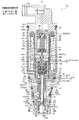
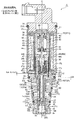
図1〜図3は、それぞれ本発明に係る可変容量型圧縮機用制御弁の一実施形態を示す縦断面図であり、図1は主弁:開、副弁:閉の状態(通常制御時)、図2は主弁:閉、副弁:閉の状態(圧縮機起動移行時)、図3は主弁:閉、副弁:開の状態(圧縮機起動時)を示している。
<First Embodiment>
1 to 3 are vertical cross-sectional views showing an embodiment of a control valve for a variable displacement compressor according to the present invention, and FIG. 1 shows a main valve: open state and a sub valve: closed state (during normal control). ), FIG. 2 shows a state where the main valve is closed and a sub valve is closed (when the compressor is started), and FIG. 3 is a state where the main valve is closed and the sub valve is open (when the compressor is started).
なお、本明細書において、上下、左右、前後等の位置、方向を表わす記述は、説明が煩瑣になるのを避けるために図面に従って便宜上付けたものであり、実際に圧縮機に組み込まれた状態での位置、方向を指すとは限らない。 In this specification, the descriptions indicating the positions and directions such as up / down, left / right, front / back, etc. are added for convenience according to the drawings in order to avoid complicated explanation, and are actually incorporated in the compressor. It does not always point to the position and direction in.
また、各図において、部材間に形成される隙間や部材間の離隔距離等は、発明の理解を容易にするため、また、作図上の便宜を図るため、各構成部材の寸法に比べて大きくあるいは小さく描かれている場合がある。 Further, in each drawing, the gap formed between the members, the separation distance between the members, etc. are larger than the dimensions of each constituent member in order to facilitate understanding of the invention and for convenience in drawing. Or it may be drawn small.
[制御弁1の構成]
図示実施形態の制御弁1は、基本的に、弁口22が設けられた弁本体20と、弁口22を開閉するための主弁体10と、該主弁体10を弁口開閉方向(上下方向)に移動させるための電磁式アクチュエータ30と、感圧応動部材としてのベローズ装置40とを備えている。
[Structure of control valve 1]
The control valve 1 of the illustrated embodiment basically has a
電磁式アクチュエータ30は、ボビン38、該ボビン38に外装された通電励磁用のコイル32、コイル32の内周側に配在されたステータ33及び吸引子34、ステータ33及び吸引子34の下端部外周(段差部)にその上端部が溶接により接合された案内パイプ35、吸引子34の下方で案内パイプ35の内周側に上下方向に摺動自在に配在された有底円筒状のプランジャ37、前記コイル32に外挿される有底穴付き円筒状のハウジング60、取付板39を介してハウジング60の上側に取り付けられたコネクタ部31、及び、ハウジング60の下端部(底部穴)と案内パイプ35の下端部との間に配在されてそれらを弁本体20の上部に固定するためのホルダ29を備えている。本例においては、円筒状のステータ33の下部内周に、該ステータ33の内径より小径の挿通穴34aがその中央に(軸線Oに沿って)形成された円筒状の吸引子34が一体成形されている。また、ステータ33の上部に形成された外周段差部とハウジング60の上部に形成された内周段差部との間にリング状の取付板39が配置されるとともに、ハウジング60の上端部(薄肉部)は、シール材としてのOリング31Aを装着するためにコネクタ部31の外周に設けられた環状の嵌凹溝31aにかしめ固定されている(かしめ部61)。ここでは、電磁式アクチュエータ30のうちの、プランジャ37を除いた、コイル32、ステータ33、及び吸引子34等からなる部分をソレノイド部30Aと称する。
The
前記ステータ33の上部には、短円柱状の固定子65が圧入等により固着せしめられ、ステータ33の内周側における前記固定子65と吸引子34との間には、圧縮機の吸入圧力Psが導入される感圧室45が形成され、この感圧室45には感圧応動部材としての、ベローズ41、逆凸字状の上ストッパ42、逆凹字状の下ストッパ43、及び圧縮コイルばね44からなるベローズ装置40が配在されている。さらに、ベローズ装置40の下側には、推力伝達部材としての段付き棒状のプッシュロッド46が軸線Oに沿って配在されている。このプッシュロッド46の略中央は大径(大径部46b)とされ、下ストッパ43の凹部内には前記プッシュロッド46の上端部46dが嵌挿されて支持され、吸引子34の挿通穴34aに前記プッシュロッド46の大径部46bが(若干の隙間34bを持って)内挿されている。また、前記プッシュロッド46の下部は、後述する断面凹状の副弁体17の凹穴17bに内挿され、その下端部46aが、凹穴17bの底部中央に形成された凹状の嵌挿穴17cに嵌め込まれている。
A
プランジャ37には、前記吸引子34の挿通穴34aと略同径の凹穴17bを有する断面凹状の副弁体17が圧入等により内挿固定されており、副弁体17とプランジャ37とが一緒に上下動するようになっている。この副弁体17は、その上端部がプランジャ37の上端部と位置合わせされ(言い換えれば、その上端部がプランジャ37の上端部内周に位置決めされ)、その下端部がプランジャ37の底部と隙間を持った状態で(後で詳述するが、主弁体10(の軸状部材10B)の鍔状係止部10kが若干の上下動可能に配置される隙間を持った状態で)、前記プランジャ37に内嵌されている。副弁体17の凹穴17bの底部中央には、前記プッシュロッド46の下端部46aが嵌挿される凹状の嵌挿穴17cが形成されている。
A
プッシュロッド46の大径部46bの上部に形成される段差部(下向きの環状の段丘面)46cとプランジャ37に内嵌された副弁体17の凹穴17bの底部(における嵌挿穴17c周りの上向きの面)との間には、円筒状の圧縮コイルばねからなるプランジャばね(開弁ばね)47が縮装されている。このプランジャばね47(の圧縮力)により、副弁体17を介してプランジャ37が下方(開弁方向)に付勢されるとともに、プッシュロッド46を介して前記ベローズ装置40が感圧室45内で保持されている。また、このプランジャばね47(の圧縮力)により、副弁体17は後述する弁内逃がし通路16(貫通逃がし孔16A)を閉じる方向に付勢されており、この副弁体17の下端部(平坦面)は、弁内逃がし通路16を開閉する副弁体部17aとされている(後で詳述)。
Around the
プランジャ37の底部には、その外周付近から中央(軸線O上)まで直線状に延びる、主弁体10(の軸状部材10B)の鍔状係止部10kを通すための通し穴付きのスリット37sが形成されている。前記スリット37sの(上下方向の)高さ(つまり、プランジャ37の底部の厚さ(上下方向の高さ))は、主弁体10の上部小径部10eの高さより若干小さくされており、主弁体10は、プランジャ37に対して上下動可能となっている(後で詳述)。また、前記スリット37sの(横方向の)幅は、組立性等を考慮して、主弁体10の上部小径部10eの外径(つまり、主弁体10を構成する軸状部材10Bの外径)より若干大きくされるとともに、主弁体10の鍔状係止部10kの外径より小さくされており、前記プランジャ37の底部上面における前記スリット37sの外周部分が、主弁体10の鍔状係止部10kを掛止するための内鍔状掛止部37kとされている。
At the bottom of the
また、本例では、副弁体17の外周の所定位置(図示例では、スリット37sの上側)に、Dカット面又は1つもしくは複数の縦溝等からなる連通溝17dが形成されており、当該連通溝17dによって、副弁体17の外周とプランジャ37の内周との間に隙間36が形成されている。
Further, in this example, a D-cut surface or a
なお、前記連通溝17をプランジャ37の外周に設け、プランジャ37の外周と案内パイプ35の内周との間に前記隙間36を形成してもよい。
The
前記したプランジャ37及び副弁体17の下側に配置される主弁体10は、例えば非磁性の金属製とされ、軸線Oに沿って配置された段付き円筒状の筒状部材10Aと、該筒状部材10Aの中央に(つまり、軸線Oに沿って)設けられた嵌装穴13に内挿固定される軸状部材10Bとの二部品構成とされている。
The
前記筒状部材10Aは、下から順に、下部嵌挿部10b、下部嵌挿部10bより若干大径の主弁体部10a、下部嵌挿部10b及び主弁体部10aより小径の中間小径部10c、並びに、上部嵌挿部10dからなっている。ここでは、下部嵌挿部10bと上部嵌挿部10dの外径(横断面積)はほぼ等しく設定されている(後で詳述)。
The
また、前記筒状部材10Aに形成された嵌装穴13は、軸状部材10Bとほぼ同径の下部小径穴13bと、軸状部材10Bより若干大径の上部大径穴13aとからなっている。本例では、当該筒状部材10Aの下部嵌挿部10b及び主弁体部10aに対応する部分が下部小径穴13bとされ、中間小径部10c及び上部嵌挿部10dに対応する部分が上部大径穴13aとされている。前記軸状部材10Bは、その上端部に比較的大径(かつ、前記副弁体17の外径より小径)の鍔状係止部10kが設けられるとともに、当該鍔状係止部10kを含む上部を突出させるようにして、前記上部大径穴13aに(環状の隙間を持って)内挿され、その下部が前記下部小径穴13bに圧入等により内嵌固定されて、筒状部材10Aと軸状部材10Bとが一体化されている。
Further, the
前記軸状部材10Bにおける嵌装穴13から突出した部分(詳しくは、軸状部材10Bにおける鍔状係止部10kと筒状部材10Aの上端部(上部嵌挿部10d)との間の部分からなる上部小径部10e)は、前記プランジャ37のスリット37sに緩く内嵌され、上部小径部10eの上側の鍔状係止部10kは、前記プランジャ37の内側における副弁体17より下側(言い換えれば、プランジャ37の底部と副弁体17の下端部との間の空間)に緩く内嵌される。前述したように、前記鍔状係止部10kは前記スリット37sの幅より大径とされており、プランジャ37が主弁体10に対して上方向に移動せしめられるとき、前記スリット37sの外周部分からなる内鍔状掛止部37kが鍔状係止部10kに引っ掛けられて抜け止め係止されるようになっている。
From the portion of the shaft-shaped
また、本例においては、軸状部材10Bの下部外周(下部小径穴13bに内嵌される部分)に、下端部から上方に延びて前記上部大径穴13aに連なる1つもしくは複数の縦溝10fが形成されており、当該縦溝10fによって、軸状部材10Bの外周と筒状部材10Aの内周(下部小径穴13b)との間に縦方向に延びる隙間が形成されている。
Further, in this example, one or a plurality of vertical grooves extending upward from the lower end portion and continuing to the upper
一方、弁本体20は、例えば、ステンレス(SUS)、高硬度真鍮、アルミニウム等の金属製とされ、その上端部(面)が、プランジャ37の最下降位置を規定するためのストッパ部20Aとなっている。
On the other hand, the
前記弁本体20は、前記主弁体10(の筒状部材10A)の下部嵌挿部10bが摺動自在に嵌挿される下側摺動孔19B及び上部嵌挿部10dが摺動自在に嵌挿される上側摺動孔19Dを有し、下側案内孔19Bと上側案内孔19Dとの間に、主弁体10の主弁体部10aにより開閉される弁口(弁シート部)22が設けられた弁室21を有する。ここでは、主弁体部10aと弁口22とで主弁部11が構成される。
In the
より詳細には、前記弁本体20の下部中央には、組立時に主弁体10を挿通させるための、上側案内孔19D及び主弁体部10aより大径の挿通穴18が設けられている。この挿通穴18の下部には、有底円筒状(言い換えれば、断面凹状)の蓋状案内部材24が圧入等により気密的に挿着固定(取付固定)されている。この蓋状案内部材24の内周は、主弁体10(の筒状部材10A)の下部嵌挿部10bが摺動自在に嵌挿される下側案内孔19Bとなっており、蓋状案内部材24(の内面)と主弁体10の下端部(下部嵌挿部10b)との間(下側案内孔19Bの下側)に、後述する吸入圧通路14を介して吸入圧力Psが導入されるPs導入室24Aが形成されている。また、蓋状案内部材24の底部と主弁体10の下端部(詳しくは、下部嵌挿部10bの下部に設けられたばね受け穴)との間(すなわち、Ps導入室24Aの内部)には、円筒状の圧縮コイルばねからなる閉弁ばね(付勢部材)50が縮装(装着)されている。この閉弁ばね50の付勢力により、主弁体10が閉弁方向(上向き)に付勢され、主弁体10(の鍔状係止部10k)の上端部は副弁体17の下端部(副弁体部17a)に押し付けられる。
More specifically, in the lower center of the
前記挿通穴18と上側案内孔19Dとの間に形成された段差部分は、前記主弁体10の主弁体部10aが下側から接離して開閉される弁口22とされている。
The stepped portion formed between the
また、前記弁本体20の上部中央には、主弁体10(の筒状部材10A)の上部嵌挿部10dより大径、かつ、前記プランジャ37の外径より小径の凹穴19Cが設けられ、前記弁本体20の上端部(面)における凹穴19C周りが前記ストッパ部20Aとなっており、この凹穴19Cの底部中央に前記上側案内孔19Dが連設されている。
Further, in the upper center of the
前記凹穴19C(言い換えれば、凹穴19Cに内挿された主弁体10の上部嵌挿部10dの外周)は、圧縮機の吸入圧力PsのPs入出室28とされており、そのPs入出室28の外周部に複数個のPs入出口27が形成されている。このPs入出口27からPs入出室28(凹穴19C内)に導入された吸入圧力Psは、プランジャ37の内部(スリット37s、及び、副弁体17とプランジャ37との間に形成される隙間36)、プッシュロッド46の外周と吸引子34との間に形成される隙間34b等を介して前記感圧室45に導入される。
The
また、前記上側摺動孔19Dの下部(主弁体10の中間小径部10cが挿通される部分)の外周部(弁口22より上流側)には、圧縮機の吐出室に連通するフィルタ25A付きPd導入口25が複数個開口せしめられ、前記弁室21(言い換えれば、挿通穴18)の外周部(弁口22の下流側)には、圧縮機のクランク室に連通するPc入出口26が複数個開口せしめられている。このPc入出口26は、弁室21→弁口22と主弁体部10aとの間の隙間→上側摺動孔19Dの下部と中間小径部10cとの間の隙間を介して前記Pd導入口25に連通する。
Further, a
また、当該制御弁1の外周部の要所には、吸入圧力Ps、吐出圧力Pd、クランク室の圧力Pcが洩れないように、シール材としてのOリング51、52、53が配在されている。
Further, O-
さらに、本実施形態では、前記主弁体10内に、Pc入出口26とPs入出室28(Ps入出口27)とを連通するための貫通逃がし孔16Aが設けられている。
Further, in the present embodiment, a
詳しくは、前記主弁体10を構成する軸状部材10Bの中央に、上端から下端付近(筒状部材10Aの主弁体部10a)まで軸線O方向に延びる縦穴16aが設けられ、その縦穴16aの下端付近から軸線O方向に対して垂直な方向に向けて横穴16bが設けられている。また、軸状部材10Bに外装される筒状部材10Aの主弁体部10aには、前記横穴16bに連なるとともに弁室21(及びPc入出口26)に開放する、前記横穴16bより若干大径の横穴からなる通し穴16cが形成されている。この筒状部材10Aの通し穴16cと軸状部材10Bの横穴16b及び縦穴16aとによって、Pc入出口26とPs入出室28とを連通する貫通逃がし孔16Aが形成されている。この貫通逃がし孔16Aは、弁内逃がし通路16の一部を構成するとともに、この貫通逃がし孔16Aの上端部(つまり、縦穴16aの上端部)が、前記副弁体17の下端部(副弁体部)17aが接離する副弁シート部23となっている(後で詳述)。ここでは、副弁シート部23と副弁体部17aとで副弁部12が構成される。
Specifically, a
本実施形態では、前記のように、Pc入出口26、弁室21、前記主弁体10に形成された貫通逃がし孔16A、プランジャ37内、Ps入出室28(凹穴19C内)などで、クランク室の圧力PcをPs入出口27を介して圧縮機の吸入室に逃がすための弁内逃がし通路16が構成され、主弁体10の貫通逃がし孔16Aの上端縁部である副弁シート部(逆立円錐台面部)23に副弁体17の副弁体部(下端部)17aが離接することにより、前記弁内逃がし通路16が開閉されるようになっている。
In the present embodiment, as described above, the Pc inlet /
さらに、上記構成に加えて、本実施形態では、前記主弁体10に作用する冷媒圧力による開弁方向(下向き)の力と閉弁方向(上向き)の力とをバランス(差圧をキャンセル)させるべく、次のような方策が講じられている。
Further, in addition to the above configuration, in the present embodiment, the force in the valve opening direction (downward) and the force in the valve closing direction (upward) due to the refrigerant pressure acting on the
すなわち、前記主弁体10内に、主弁体10の上端部側に設けられたPs入出室28(Ps入出口27)又は感圧室45と主弁体10の下端部側に設けられたPs導入室24Aとを連通するための吸入圧通路14が設けられている。
That is, in the
詳しくは、前記した主弁体10の筒状部材10Aの上部大径穴13aと軸状部材10Bの下部外周の縦溝10fによって、主弁体10における筒状部材10Aと軸状部材10Bとの間に、Ps入出室28(Ps入出口27)又は感圧室45とPs導入室24Aとを連通する吸入圧通路14が形成されている。換言すれば、本例においては、前記主弁体10内に形成された貫通逃がし孔16Aの周囲に、当該吸入圧通路14が配在されていることになる。この吸入圧通路14によって、主弁体10の上端部側に作用する吸入圧力Psが、当該主弁体10の下端部に設けられたPs導入室24Aに導かれ、主弁体10の下端部(下部嵌挿部10b)に前記吸入圧力Psが(常時)作用するようにされている。
Specifically, the
また、主弁体10の下部嵌挿部10bの外径(横断面積Ab)(言い換えれば、下側摺動孔19Bの孔径(開口面積すなわち受圧面積))、弁口22の口径(横断面積もしくは実効開口面積Ac)、及び主弁体10の上部嵌挿部10dの外径(横断面積Ad)(言い換えれば、上側摺動孔19Dの孔径(開口面積すなわち受圧面積))がほぼ等しく設定されている(図4参照)。
Further, the outer diameter (cross-sectional area Ab) of the lower
このような構成とされた制御弁1においては、主弁体10に作用する冷媒圧力によって、開弁方向(下向き)及び閉弁方向(上向き)にそれぞれ次のような力がかかる(図4参照)。
開弁方向にかかる力=Ps×Ad+Pd×Ac+Pc×Ab
閉弁方向にかかる力=Pd×Ad+Pc×Ac+Ps×Ab
In the control valve 1 having such a configuration, the following forces are applied in the valve opening direction (downward) and the valve closing direction (upward), respectively, depending on the refrigerant pressure acting on the main valve body 10 (see FIG. 4). ).
Force applied in the valve opening direction = Ps × Ad + Pd × Ac + Pc × Ab
Force applied in the valve closing direction = Pd × Ad + Pc × Ac + Ps × Ab
ここで、前述したように、主弁体10の下部嵌挿部10bの横断面積Ab、弁口22の実効開口面積Ac、及び主弁体10の上部嵌挿部10dの横断面積Adがほぼ同じとされている(Ab=Ac=Ad)ので、開弁方向にかかる力と閉弁方向にかかる力とがほぼ同じに(相殺)される。
Here, as described above, the cross-sectional area Ab of the lower
なお、上記実施形態では、主弁体10を筒状部材10Aと軸状部材10Bとの二部品構成とし、その筒状部材10Aと軸状部材10Bとの間に、縦方向(軸線O方向、弁口22開閉方向)に略直線状に延びる吸入圧通路14が形成されているが、例えば、主弁体10を一部品で構成し、その主弁体10の内部に吸入圧通路14を形成してもよいことは勿論である。
In the above embodiment, the
また、上記実施形態では、クランク室の圧力PcをPs入出口27を介して圧縮機の吸入室に逃がすための弁内逃がし通路16が、主弁体10内にクランク状に形成された貫通逃がし孔16Aを含んで構成されているが、例えば、弁内逃がし通路16を(主弁体10内ではなく)弁本体20側に設けてもよいことは詳述するまでも無い。また、当該弁内逃がし通路16自体を、省略してもよいことは勿論である。
Further, in the above embodiment, the valve in-
また、前記吸入圧通路14や弁内逃がし通路16(貫通逃がし孔16A)の形成方法や形状、配置態様等は、図示例に限られないことは当然である。
Further, it is natural that the method, shape, arrangement mode, etc. of the
ここで、本実施形態の制御弁1では、図1に示される如くに、プランジャ37、主弁体10、及び副弁体17が最下降位置にある状態(プランジャ37の最下端面がストッパ部20Aに当接、主弁部11は全開、副弁部12は全閉)において、主弁体10の主弁体部10aと弁口(弁シート部)22との間の上下方向の離隔距離が第1リフト量Laとされ、プランジャ37の内鍔状掛止部37kと主弁体10の鍔状係止部10kとの離隔距離は所定量Lyとされ、前記プランジャ37の最大リフト量(第2リフト量)Lb(プランジャ37の最下降位置から最上昇位置までのリフト量)は、第1リフト量La+所定量Lyとなっている。
Here, in the control valve 1 of the present embodiment, as shown in FIG. 1, the
[制御弁1の動作]
次に、上記構成とされた制御弁1の動作を概説する。
[Operation of control valve 1]
Next, the operation of the control valve 1 having the above configuration will be outlined.
なお、本例の制御弁1では、前記した吸入圧通路14を通して、主弁体10に作用する冷媒圧力による開弁方向(下向き)の力と閉弁方向(上向き)の力(すなわち、主弁体10の移動方向(軸線O方向)に作用する力)が常時バランス(差圧がキャンセル)されている。
In the control valve 1 of this example, a valve opening direction (downward) force and a valve closing direction (upward) force (that is, the main valve) due to the refrigerant pressure acting on the
通常制御時(Pd→Pc制御時)には、プランジャ37(及び副弁体17)のリフト量は、最大でも前記第1リフト量La強とされ、圧縮機起動時(Pc→Ps制御時)には、プランジャ37(及び副弁体17)のリフト量は、前記第2リフト量Lbとされる。 During normal control (Pd → Pc control), the lift amount of the plunger 37 (and the auxiliary valve body 17) is set to be stronger than the first lift amount La at the maximum, and when the compressor is started (Pc → Ps control). The lift amount of the plunger 37 (and the auxiliary valve body 17) is the second lift amount Lb.
すなわち、通常制御時(Pd→Pc制御時)には、コイル32、ステータ33及び吸引子34等からなるソレノイド部30Aが通電励磁されると、吸引子34にプランジャ37及び副弁体17が共に(上方向に)引き寄せられ、この動きに追従して、閉弁ばね50の付勢力により主弁体10が上方(閉弁方向)に移動せしめられる。一方、圧縮機からPs入出口27に導入された吸入圧力Psは、Ps入出室28からプランジャ37の内部(スリット37s及び副弁体17の外周とプランジャ37との間の隙間36)等を介して感圧室45に導入され、ベローズ装置40(内部は真空圧)は感圧室45の圧力(吸入圧力Ps)に応じて伸縮変位(吸入圧力Psが高いと収縮、低いと伸張)し、該変位がプッシュロッド46や副弁体17等を介して主弁体10に伝達され、それによって、弁開度(弁口22と主弁体部10aとの離隔距離)が調整され、その弁開度に応じて、クランク室の圧力Pcが調整される。
That is, during normal control (during Pd → Pc control), when the
この場合、主弁体10は閉弁ばね50の付勢力により常に上向きに付勢されているとともに、副弁体17は開弁ばね47の付勢力により常に下向きに付勢されているので、副弁体部17aは副弁シート部23に押し付けられた状態(副弁部12が閉弁)となり、弁内逃がし通路16は主弁体10内で遮断されている。そのため、弁内逃がし通路16を通じてクランク室の圧力Pcが吸入室に逃がされることはない。
In this case, the
それに対し、圧縮機起動時には、ソレノイド部30Aが通電励磁されて、吸引子34にプランジャ37及び副弁体17が共に(上方向に)引き寄せられ、この上方向移動に追従して主弁体10が上方向に移動せしめられ、主弁体10の主弁体部10aにより弁口22が閉じられた後、さらにプランジャ37及び副弁体17が上方向に移動せしめられ、これによって副弁体17が弁内逃がし通路16を開くようにされ、クランク室の圧力Pcが弁内逃がし通路16を通じて吸入室に逃がされる。
On the other hand, when the compressor is started, the
詳細には、プランジャ37(及び副弁体17B)の上方向移動量が第1リフト量Laに達するまでは、主弁体10が閉弁ばね50の付勢力によりプランジャ37及び副弁体17の上方向移動に追従するように閉弁方向に移動し、前記上方向移動量が前記第1リフト量Laに達すると、主弁体10の主弁体部10aにより弁口22が閉じられ(図2に示す状態)、この主弁部11の閉弁状態からさらにプランジャ37及び副弁体17が前記所定量Ly分上方向に移動せしめられる(図3に示す状態)。言い換えれば、プランジャ37及び副弁体17の上方向移動量が前記第1リフト量Laに達した後、プランジャ37の内鍔状掛止部37kが主弁体10の鍔状係止部10kに係止されるまでの所定量Ly分だけ副弁体17がプランジャ37と共に吸引子34側に引き寄せられる(第1リフト量La+所定量Ly=第2リフト量Lb)。この場合、主弁体10は閉弁状態のまま不動であるので、副弁体17の副弁体部17aは、副弁シート部23から所定量Ly分リフトせしめられ、これによって弁内逃がし通路16が開かれる。プランジャ37の内鍔状掛止部37kが主弁体10の鍔状係止部10kに係止されると、ソレノイド部30Aが吸引力を発生しても、プランジャ37及び副弁体17はそれ以上引き上げられない。
Specifically, until the upward movement amount of the plunger 37 (and the sub-valve body 17B) reaches the first lift amount La, the
このように、本実施形態の制御弁1においては、圧縮機起動時に、クランク室の圧力Pcは弁内逃がし通路16を通じて吸入室に逃がされることになるため、圧縮機起動時において吐出容量が大きくなるまでに要する時間を大幅に短縮することができる。また、通常制御時(Pd→Pc制御時)には、弁内逃がし通路16は副弁体17により閉じられているため、圧縮機の運転効率が低下することはない。
As described above, in the control valve 1 of the present embodiment, the pressure Pc in the crank chamber is released to the suction chamber through the valve
また、本実施形態の制御弁1においては、主弁体10に、主弁体10の上端部に作用する吸入圧力Psを主弁体10の下端部に設けられたPs導入室24Aに導き、主弁体10の下端部に吸入圧力Psを(常時)作用させるための吸入圧通路14が設けられるので、例えば、弁本体に吸入圧通路等が設けられた従来のものと比べて、弁本体20の体格を大きくすることなく、主弁体10に作用する冷媒圧力の影響をキャンセルさせることができる。
Further, in the control valve 1 of the present embodiment, the suction pressure Ps acting on the upper end portion of the
より詳しくは、本実施形態の制御弁1は、主弁体10の上端部に吸入圧力Psが作用するようにされるとともに、主弁体10の下端部に吸入圧力Psが導入されるPs導入室24Aが設けられ、主弁体10に、前記吸入圧力Psを前記Ps導入室24Aに導く吸入圧通路14が設けられるので、主弁体10の下部嵌挿部10bの横断面積Ab、弁口22の実効開口面積Ac、及び上部嵌挿部10dの横断面積Adを同じにすれば、主弁体10に作用する冷媒圧力による開弁方向にかかる力と閉弁方向にかかる力とは同じに(相殺)されるため、主弁体10に作用する冷媒圧力による制御への悪影響を受け難くできる。
More specifically, in the control valve 1 of the present embodiment, the suction pressure Ps is applied to the upper end portion of the
また、主弁体20は、主弁体部10a等を有する筒状部材10Aと、筒状部材10Aに内嵌固定される軸状部材10Bとで構成され、筒状部材10Aと軸状部材10Bとの間に吸入圧通路14が形成されるので、簡単な構造でもって、当該吸入圧通路14を形成することができ、主弁体10に作用する冷媒圧力の影響をキャンセルさせることができる。
Further, the
1 可変容量型圧縮機用制御弁
10 主弁体
10A 筒状部材
10B 軸状部材
10a 主弁体部
10b 下部嵌挿部
10c 中間小径部
10d 上部嵌挿部
10e 上部小径部
10f 縦溝
10k 鍔状係止部
11 主弁部
12 副弁部
13 嵌装穴
13a 上部大径穴
13b 下部小径穴
14 吸入圧通路
16 弁内逃がし通路
16A 貫通逃がし孔
16a 縦穴
16b 横穴
16c 通し穴
17 副弁体
17a 副弁体部
17d 連通溝
18 挿通穴
19B 下側案内孔
19C 凹穴
19D 上側案内孔
20 弁本体
20A ストッパ部
21 弁室
22 弁口
23 副弁シート部
24 蓋状案内部材
24A Ps導入室
25 Pd導入口
26 Pc入出口
27 Ps入出口
28 Ps入出室
30 電磁式アクチュエータ
30A ソレノイド部
32 コイル
33 ステータ
34 吸引子
37 プランジャ
37s スリット
40 ベローズ装置(感圧応動部材)
45 感圧室
46 プッシュロッド
50 閉弁ばね(付勢部材)
1 Control valve for
45 Pressure-
Claims (8)
前記主弁体部が接離する弁口が設けられた弁室と圧縮機の吸入室に連通するPs入出口とを有し、前記弁口より上流側に圧縮機の吐出室に連通するPd導入口が設けられるとともに、前記弁口より下流側に前記圧縮機のクランク室に連通するPc入出口が設けられた弁本体と、
前記主弁体を弁口開閉方向に移動させるための電磁式アクチュエータと、
前記圧縮機から吸入圧力Psが前記Ps入出口を介して導入される感圧室と、
前記感圧室の圧力に応じて前記主弁体を弁口開閉方向に付勢する感圧応動部材と、を備え、
前記主弁体の一端部に、前記Ps入出口又は前記感圧室が設けられて前記吸入圧力Psが作用するようにされるとともに、前記主弁体に、前記吸入圧力Psを前記主弁体の他端部に設けられたPs導入室に導き、該主弁体の他端部に前記吸入圧力Psを作用させるための吸入圧通路が設けられており、
前記主弁体は、前記主弁体部を有する筒状部材と、該筒状部材に内嵌固定される軸状部材とで構成され、前記筒状部材と前記軸状部材との間に前記吸入圧通路が形成されていることを特徴とする可変容量型圧縮機用制御弁。 A main valve body having a main valve body part and
Pd which has a valve chamber provided with a valve port to which the main valve body portion contacts and detaches and a Ps inlet / outlet which communicates with the suction chamber of the compressor, and communicates with the discharge chamber of the compressor on the upstream side of the valve port. A valve body provided with an introduction port and a Pc inlet / outlet communicating with the crank chamber of the compressor on the downstream side of the valve port.
An electromagnetic actuator for moving the main valve body in the valve opening opening / closing direction, and
A pressure-sensitive chamber in which suction pressure Ps is introduced from the compressor through the Ps inlet / outlet, and
A pressure-sensitive sensitive member that urges the main valve body in the valve opening opening / closing direction according to the pressure in the pressure-sensitive chamber is provided.
The Ps inlet / outlet or the pressure sensitive chamber is provided at one end of the main valve body so that the suction pressure Ps acts on the main valve body, and the suction pressure Ps is applied to the main valve body. A suction pressure passage for guiding the Ps introduction chamber to the other end of the main valve body and applying the suction pressure Ps to the other end of the main valve body is provided.
The main valve body is composed of a tubular member having the main valve body portion and a shaft-shaped member that is internally fitted and fixed to the tubular member, and is said to be between the tubular member and the shaft-shaped member. A control valve for a variable displacement compressor, characterized in that an suction pressure passage is formed.
前記主弁体に作用する冷媒圧力による開弁方向の力と閉弁方向の力とが同じになるように、前記主弁体の一端側嵌挿部の横断面積、前記主弁体の他端側嵌挿部の横断面積、及び前記弁口の開口面積が等しく設定されていることを特徴とする請求項1に記載の可変容量型圧縮機用制御弁。 One end side guide hole for slidably fitting the one end side fitting portion of the main valve body is provided on one end side of the valve body from the valve opening, and on the other end side of the valve opening of the valve body. The other end side guide hole into which the other end side fitting portion of the main valve body is slidably fitted is provided, and the Ps inlet / outlet or the pressure sensitive chamber is provided on one end side of the one end side guide hole. , The Ps introduction chamber is provided on the other end side of the other end side guide hole.
The cross-sectional area of one end side fitting portion of the main valve body and the other end of the main valve body so that the force in the valve opening direction and the force in the valve closing direction due to the refrigerant pressure acting on the main valve body are the same. The control valve for a variable displacement compressor according to claim 1, wherein the cross-sectional area of the side fitting portion and the opening area of the valve port are set to be equal.
前記弁内逃がし通路は、前記軸状部材に設けられた縦穴を含んで構成されていることを特徴とする請求項1から5のいずれか一項に記載の可変容量型圧縮機用制御弁。 An in-valve relief passage for releasing the pressure Pc of the crank chamber to the suction chamber of the compressor via the Ps inlet / outlet is provided in the main valve body, and a sub-valve body that opens and closes the in-valve relief passage is provided. Provided,
The control valve for a variable displacement compressor according to any one of claims 1 to 5, wherein the relief passage in the valve includes a vertical hole provided in the shaft-shaped member.
Priority Applications (6)
| Application Number | Priority Date | Filing Date | Title |
|---|---|---|---|
| JP2018012181A JP6906233B2 (en) | 2018-01-29 | 2018-01-29 | Control valve for variable displacement compressor |
| PCT/JP2019/000120 WO2019146388A1 (en) | 2018-01-29 | 2019-01-08 | Control valve for variable displacement compressor |
| KR1020207024761A KR20200110440A (en) | 2018-01-29 | 2019-01-08 | Control valve for variable displacement compressor |
| EP19743098.6A EP3748157A4 (en) | 2018-01-29 | 2019-01-08 | Control valve for variable displacement compressor |
| US16/964,044 US20210048010A1 (en) | 2018-01-29 | 2019-01-08 | Variable-capacity compressor control valve |
| CN201980010725.XA CN111670305A (en) | 2018-01-29 | 2019-01-08 | Control valve for variable displacement compressor |
Applications Claiming Priority (1)
| Application Number | Priority Date | Filing Date | Title |
|---|---|---|---|
| JP2018012181A JP6906233B2 (en) | 2018-01-29 | 2018-01-29 | Control valve for variable displacement compressor |
Publications (3)
| Publication Number | Publication Date |
|---|---|
| JP2019132132A JP2019132132A (en) | 2019-08-08 |
| JP2019132132A5 JP2019132132A5 (en) | 2020-04-23 |
| JP6906233B2 true JP6906233B2 (en) | 2021-07-21 |
Family
ID=67395952
Family Applications (1)
| Application Number | Title | Priority Date | Filing Date |
|---|---|---|---|
| JP2018012181A Active JP6906233B2 (en) | 2018-01-29 | 2018-01-29 | Control valve for variable displacement compressor |
Country Status (6)
| Country | Link |
|---|---|
| US (1) | US20210048010A1 (en) |
| EP (1) | EP3748157A4 (en) |
| JP (1) | JP6906233B2 (en) |
| KR (1) | KR20200110440A (en) |
| CN (1) | CN111670305A (en) |
| WO (1) | WO2019146388A1 (en) |
Families Citing this family (1)
| Publication number | Priority date | Publication date | Assignee | Title |
|---|---|---|---|---|
| US11300219B2 (en) * | 2020-07-28 | 2022-04-12 | Mahle International Gmbh | Variable-capacity compressor control valve |
Family Cites Families (10)
| Publication number | Priority date | Publication date | Assignee | Title |
|---|---|---|---|---|
| JPS5553514Y2 (en) | 1975-03-18 | 1980-12-11 | ||
| JP4829419B2 (en) * | 2001-04-06 | 2011-12-07 | 株式会社不二工機 | Control valve for variable displacement compressor |
| JP4046530B2 (en) * | 2002-03-26 | 2008-02-13 | 株式会社テージーケー | Capacity control valve for variable capacity compressor |
| JP4550651B2 (en) | 2005-04-14 | 2010-09-22 | 株式会社不二工機 | Control valve for variable displacement compressor |
| JP2008223482A (en) * | 2007-03-08 | 2008-09-25 | Tgk Co Ltd | Control valve for variable capacity compressor |
| JP4959525B2 (en) * | 2007-11-29 | 2012-06-27 | 株式会社不二工機 | Control valve for variable displacement compressor |
| JP5553514B2 (en) | 2009-02-10 | 2014-07-16 | 株式会社不二工機 | Control valve for variable displacement compressor |
| JP2011163313A (en) * | 2010-02-15 | 2011-08-25 | Shinhan Electro-Mechanics Co Ltd | Capacity control valve for variable displacement compressor, and assembling method of the same |
| JP2012026311A (en) * | 2010-07-21 | 2012-02-09 | Fuji Koki Corp | Control valve for variable displacement compressor |
| JP6355617B2 (en) * | 2015-12-16 | 2018-07-11 | 株式会社不二工機 | Control valve for variable displacement compressor |
-
2018
- 2018-01-29 JP JP2018012181A patent/JP6906233B2/en active Active
-
2019
- 2019-01-08 KR KR1020207024761A patent/KR20200110440A/en not_active Application Discontinuation
- 2019-01-08 EP EP19743098.6A patent/EP3748157A4/en not_active Withdrawn
- 2019-01-08 US US16/964,044 patent/US20210048010A1/en not_active Abandoned
- 2019-01-08 CN CN201980010725.XA patent/CN111670305A/en active Pending
- 2019-01-08 WO PCT/JP2019/000120 patent/WO2019146388A1/en unknown
Also Published As
| Publication number | Publication date |
|---|---|
| CN111670305A (en) | 2020-09-15 |
| EP3748157A4 (en) | 2021-12-01 |
| JP2019132132A (en) | 2019-08-08 |
| US20210048010A1 (en) | 2021-02-18 |
| KR20200110440A (en) | 2020-09-23 |
| EP3748157A1 (en) | 2020-12-09 |
| WO2019146388A1 (en) | 2019-08-01 |
Similar Documents
| Publication | Publication Date | Title |
|---|---|---|
| JP6271660B2 (en) | Control valve for variable displacement compressor | |
| JP4504243B2 (en) | Control valve for variable displacement compressor | |
| JP6626789B2 (en) | Control valve for variable displacement compressor | |
| JP2022025056A (en) | Variable-capacity compressor control valve | |
| KR20060105531A (en) | Control valve for variable displacement compressor | |
| JP4714626B2 (en) | Control valve for variable displacement compressor | |
| JP4550651B2 (en) | Control valve for variable displacement compressor | |
| WO2018003253A1 (en) | Control valve for variable-capacity compressor | |
| KR20170072144A (en) | Variable-capacity compressor control valve | |
| CN109715943B (en) | Control valve for variable displacement compressor | |
| JP6906233B2 (en) | Control valve for variable displacement compressor | |
| JP6647156B2 (en) | Control valve for variable displacement compressor | |
| JP5468932B2 (en) | Solenoid control valve | |
| WO2018003249A1 (en) | Control valve for variable-capacity compressor | |
| JP6757074B2 (en) | Control valve for variable displacement compressor | |
| JP6708911B2 (en) | Control valve for variable displacement compressor | |
| JP2006291864A (en) | Control valve for variable displacement compressor | |
| KR20190005936A (en) | Control valve for variable capacity type compressor and method of assembling thereof |
Legal Events
| Date | Code | Title | Description |
|---|---|---|---|
| A521 | Written amendment |
Free format text: JAPANESE INTERMEDIATE CODE: A523 Effective date: 20200316 |
|
| A621 | Written request for application examination |
Free format text: JAPANESE INTERMEDIATE CODE: A621 Effective date: 20200316 |
|
| A131 | Notification of reasons for refusal |
Free format text: JAPANESE INTERMEDIATE CODE: A131 Effective date: 20210126 |
|
| A521 | Written amendment |
Free format text: JAPANESE INTERMEDIATE CODE: A523 Effective date: 20210324 |
|
| TRDD | Decision of grant or rejection written | ||
| A01 | Written decision to grant a patent or to grant a registration (utility model) |
Free format text: JAPANESE INTERMEDIATE CODE: A01 Effective date: 20210525 |
|
| A61 | First payment of annual fees (during grant procedure) |
Free format text: JAPANESE INTERMEDIATE CODE: A61 Effective date: 20210622 |
|
| R150 | Certificate of patent or registration of utility model |
Ref document number: 6906233 Country of ref document: JP Free format text: JAPANESE INTERMEDIATE CODE: R150 |