JP6905939B2 - How to determine the chemical composition of the slag moiety - Google Patents
How to determine the chemical composition of the slag moiety Download PDFInfo
- Publication number
- JP6905939B2 JP6905939B2 JP2017559405A JP2017559405A JP6905939B2 JP 6905939 B2 JP6905939 B2 JP 6905939B2 JP 2017559405 A JP2017559405 A JP 2017559405A JP 2017559405 A JP2017559405 A JP 2017559405A JP 6905939 B2 JP6905939 B2 JP 6905939B2
- Authority
- JP
- Japan
- Prior art keywords
- values
- matrix
- chemical composition
- steel
- slag
- Prior art date
- Legal status (The legal status is an assumption and is not a legal conclusion. Google has not performed a legal analysis and makes no representation as to the accuracy of the status listed.)
- Active
Links
- 239000000203 mixture Substances 0.000 title claims description 60
- 239000002893 slag Substances 0.000 title claims description 52
- 239000000126 substance Substances 0.000 title claims description 44
- 238000000034 method Methods 0.000 claims description 60
- 230000003595 spectral effect Effects 0.000 claims description 48
- 239000011159 matrix material Substances 0.000 claims description 45
- 229910000831 Steel Inorganic materials 0.000 claims description 39
- 239000010959 steel Substances 0.000 claims description 39
- 230000003287 optical effect Effects 0.000 claims description 19
- 238000012549 training Methods 0.000 claims description 16
- 239000000654 additive Substances 0.000 claims description 14
- 230000008569 process Effects 0.000 claims description 14
- 238000012706 support-vector machine Methods 0.000 claims description 5
- 230000009467 reduction Effects 0.000 claims description 3
- 230000000996 additive effect Effects 0.000 claims description 2
- YGSDEFSMJLZEOE-UHFFFAOYSA-M salicylate Chemical compound OC1=CC=CC=C1C([O-])=O YGSDEFSMJLZEOE-UHFFFAOYSA-M 0.000 claims 1
- 229960001860 salicylate Drugs 0.000 claims 1
- 238000004519 manufacturing process Methods 0.000 description 9
- 229910052760 oxygen Inorganic materials 0.000 description 9
- QVGXLLKOCUKJST-UHFFFAOYSA-N atomic oxygen Chemical compound [O] QVGXLLKOCUKJST-UHFFFAOYSA-N 0.000 description 8
- 239000001301 oxygen Substances 0.000 description 8
- 229910052751 metal Inorganic materials 0.000 description 7
- 239000002184 metal Substances 0.000 description 7
- 238000004458 analytical method Methods 0.000 description 6
- 238000006243 chemical reaction Methods 0.000 description 6
- 229910001341 Crude steel Inorganic materials 0.000 description 5
- 229910000805 Pig iron Inorganic materials 0.000 description 5
- 229910052698 phosphorus Inorganic materials 0.000 description 5
- 239000012535 impurity Substances 0.000 description 4
- 238000010606 normalization Methods 0.000 description 4
- 229910052717 sulfur Inorganic materials 0.000 description 4
- 238000010586 diagram Methods 0.000 description 3
- 238000010891 electric arc Methods 0.000 description 3
- 238000009499 grossing Methods 0.000 description 3
- 238000005549 size reduction Methods 0.000 description 3
- 238000004876 x-ray fluorescence Methods 0.000 description 3
- 235000008733 Citrus aurantifolia Nutrition 0.000 description 2
- 229910001021 Ferroalloy Inorganic materials 0.000 description 2
- XEEYBQQBJWHFJM-UHFFFAOYSA-N Iron Chemical compound [Fe] XEEYBQQBJWHFJM-UHFFFAOYSA-N 0.000 description 2
- OAICVXFJPJFONN-UHFFFAOYSA-N Phosphorus Chemical compound [P] OAICVXFJPJFONN-UHFFFAOYSA-N 0.000 description 2
- VYPSYNLAJGMNEJ-UHFFFAOYSA-N Silicium dioxide Chemical compound O=[Si]=O VYPSYNLAJGMNEJ-UHFFFAOYSA-N 0.000 description 2
- 235000011941 Tilia x europaea Nutrition 0.000 description 2
- GWEVSGVZZGPLCZ-UHFFFAOYSA-N Titan oxide Chemical compound O=[Ti]=O GWEVSGVZZGPLCZ-UHFFFAOYSA-N 0.000 description 2
- MCMNRKCIXSYSNV-UHFFFAOYSA-N Zirconium dioxide Chemical compound O=[Zr]=O MCMNRKCIXSYSNV-UHFFFAOYSA-N 0.000 description 2
- 238000004364 calculation method Methods 0.000 description 2
- 150000001875 compounds Chemical class 0.000 description 2
- QDOXWKRWXJOMAK-UHFFFAOYSA-N dichromium trioxide Chemical compound O=[Cr]O[Cr]=O QDOXWKRWXJOMAK-UHFFFAOYSA-N 0.000 description 2
- 239000010459 dolomite Substances 0.000 description 2
- 229910000514 dolomite Inorganic materials 0.000 description 2
- 230000000694 effects Effects 0.000 description 2
- 230000004907 flux Effects 0.000 description 2
- 238000003384 imaging method Methods 0.000 description 2
- 229910052500 inorganic mineral Inorganic materials 0.000 description 2
- UQSXHKLRYXJYBZ-UHFFFAOYSA-N iron oxide Inorganic materials [Fe]=O UQSXHKLRYXJYBZ-UHFFFAOYSA-N 0.000 description 2
- 239000004571 lime Substances 0.000 description 2
- 239000007788 liquid Substances 0.000 description 2
- 239000011707 mineral Substances 0.000 description 2
- 230000003647 oxidation Effects 0.000 description 2
- 238000007254 oxidation reaction Methods 0.000 description 2
- 230000001590 oxidative effect Effects 0.000 description 2
- 239000011574 phosphorus Substances 0.000 description 2
- 238000007670 refining Methods 0.000 description 2
- 230000011218 segmentation Effects 0.000 description 2
- 238000012360 testing method Methods 0.000 description 2
- OYPRJOBELJOOCE-UHFFFAOYSA-N Calcium Chemical compound [Ca] OYPRJOBELJOOCE-UHFFFAOYSA-N 0.000 description 1
- OKTJSMMVPCPJKN-UHFFFAOYSA-N Carbon Chemical compound [C] OKTJSMMVPCPJKN-UHFFFAOYSA-N 0.000 description 1
- MYMOFIZGZYHOMD-UHFFFAOYSA-N Dioxygen Chemical compound O=O MYMOFIZGZYHOMD-UHFFFAOYSA-N 0.000 description 1
- KKCBUQHMOMHUOY-UHFFFAOYSA-N Na2O Inorganic materials [O-2].[Na+].[Na+] KKCBUQHMOMHUOY-UHFFFAOYSA-N 0.000 description 1
- 238000003723 Smelting Methods 0.000 description 1
- NINIDFKCEFEMDL-UHFFFAOYSA-N Sulfur Chemical compound [S] NINIDFKCEFEMDL-UHFFFAOYSA-N 0.000 description 1
- 229910052782 aluminium Inorganic materials 0.000 description 1
- XAGFODPZIPBFFR-UHFFFAOYSA-N aluminium Chemical compound [Al] XAGFODPZIPBFFR-UHFFFAOYSA-N 0.000 description 1
- PNEYBMLMFCGWSK-UHFFFAOYSA-N aluminium oxide Inorganic materials [O-2].[O-2].[O-2].[Al+3].[Al+3] PNEYBMLMFCGWSK-UHFFFAOYSA-N 0.000 description 1
- 230000015572 biosynthetic process Effects 0.000 description 1
- 239000011575 calcium Substances 0.000 description 1
- 229910052791 calcium Inorganic materials 0.000 description 1
- WUKWITHWXAAZEY-UHFFFAOYSA-L calcium difluoride Chemical compound [F-].[F-].[Ca+2] WUKWITHWXAAZEY-UHFFFAOYSA-L 0.000 description 1
- ODINCKMPIJJUCX-UHFFFAOYSA-N calcium oxide Inorganic materials [Ca]=O ODINCKMPIJJUCX-UHFFFAOYSA-N 0.000 description 1
- 229910052799 carbon Inorganic materials 0.000 description 1
- 230000008859 change Effects 0.000 description 1
- 229910052729 chemical element Inorganic materials 0.000 description 1
- 229910052681 coesite Inorganic materials 0.000 description 1
- 239000003086 colorant Substances 0.000 description 1
- 238000012937 correction Methods 0.000 description 1
- 229910052593 corundum Inorganic materials 0.000 description 1
- 229910052906 cristobalite Inorganic materials 0.000 description 1
- 238000005261 decarburization Methods 0.000 description 1
- 238000006477 desulfuration reaction Methods 0.000 description 1
- 230000023556 desulfurization Effects 0.000 description 1
- 230000001627 detrimental effect Effects 0.000 description 1
- 230000007613 environmental effect Effects 0.000 description 1
- 238000011156 evaluation Methods 0.000 description 1
- 239000000835 fiber Substances 0.000 description 1
- 238000005188 flotation Methods 0.000 description 1
- 239000010436 fluorite Substances 0.000 description 1
- 239000010439 graphite Substances 0.000 description 1
- 229910002804 graphite Inorganic materials 0.000 description 1
- 229910052736 halogen Inorganic materials 0.000 description 1
- 150000002367 halogens Chemical class 0.000 description 1
- 229910052739 hydrogen Inorganic materials 0.000 description 1
- 229910052742 iron Inorganic materials 0.000 description 1
- JEIPFZHSYJVQDO-UHFFFAOYSA-N iron(III) oxide Inorganic materials O=[Fe]O[Fe]=O JEIPFZHSYJVQDO-UHFFFAOYSA-N 0.000 description 1
- 229910001338 liquidmetal Inorganic materials 0.000 description 1
- CPLXHLVBOLITMK-UHFFFAOYSA-N magnesium oxide Inorganic materials [Mg]=O CPLXHLVBOLITMK-UHFFFAOYSA-N 0.000 description 1
- WPBNNNQJVZRUHP-UHFFFAOYSA-L manganese(2+);methyl n-[[2-(methoxycarbonylcarbamothioylamino)phenyl]carbamothioyl]carbamate;n-[2-(sulfidocarbothioylamino)ethyl]carbamodithioate Chemical compound [Mn+2].[S-]C(=S)NCCNC([S-])=S.COC(=O)NC(=S)NC1=CC=CC=C1NC(=S)NC(=O)OC WPBNNNQJVZRUHP-UHFFFAOYSA-L 0.000 description 1
- VASIZKWUTCETSD-UHFFFAOYSA-N manganese(II) oxide Inorganic materials [Mn]=O VASIZKWUTCETSD-UHFFFAOYSA-N 0.000 description 1
- 238000002844 melting Methods 0.000 description 1
- 230000008018 melting Effects 0.000 description 1
- 229910001092 metal group alloy Inorganic materials 0.000 description 1
- 229910052752 metalloid Inorganic materials 0.000 description 1
- 150000002739 metals Chemical class 0.000 description 1
- 230000004048 modification Effects 0.000 description 1
- 238000012986 modification Methods 0.000 description 1
- 229910052757 nitrogen Inorganic materials 0.000 description 1
- 230000037361 pathway Effects 0.000 description 1
- 238000004886 process control Methods 0.000 description 1
- 238000012545 processing Methods 0.000 description 1
- 238000003672 processing method Methods 0.000 description 1
- 238000000746 purification Methods 0.000 description 1
- 230000004044 response Effects 0.000 description 1
- 230000002000 scavenging effect Effects 0.000 description 1
- 229910052710 silicon Inorganic materials 0.000 description 1
- 239000010703 silicon Substances 0.000 description 1
- 239000000377 silicon dioxide Substances 0.000 description 1
- 235000012239 silicon dioxide Nutrition 0.000 description 1
- 239000007787 solid Substances 0.000 description 1
- 238000000638 solvent extraction Methods 0.000 description 1
- 238000001228 spectrum Methods 0.000 description 1
- 239000010935 stainless steel Substances 0.000 description 1
- 229910001220 stainless steel Inorganic materials 0.000 description 1
- 229910052682 stishovite Inorganic materials 0.000 description 1
- 239000011593 sulfur Substances 0.000 description 1
- 230000007704 transition Effects 0.000 description 1
- 229910052905 tridymite Inorganic materials 0.000 description 1
- 238000012795 verification Methods 0.000 description 1
- 230000000007 visual effect Effects 0.000 description 1
- 239000002699 waste material Substances 0.000 description 1
- 229910001845 yogo sapphire Inorganic materials 0.000 description 1
Images


Classifications
-
- G—PHYSICS
- G01—MEASURING; TESTING
- G01N—INVESTIGATING OR ANALYSING MATERIALS BY DETERMINING THEIR CHEMICAL OR PHYSICAL PROPERTIES
- G01N21/00—Investigating or analysing materials by the use of optical means, i.e. using sub-millimetre waves, infrared, visible or ultraviolet light
- G01N21/84—Systems specially adapted for particular applications
- G01N21/85—Investigating moving fluids or granular solids
-
- G—PHYSICS
- G01—MEASURING; TESTING
- G01J—MEASUREMENT OF INTENSITY, VELOCITY, SPECTRAL CONTENT, POLARISATION, PHASE OR PULSE CHARACTERISTICS OF INFRARED, VISIBLE OR ULTRAVIOLET LIGHT; COLORIMETRY; RADIATION PYROMETRY
- G01J3/00—Spectrometry; Spectrophotometry; Monochromators; Measuring colours
- G01J3/12—Generating the spectrum; Monochromators
- G01J3/14—Generating the spectrum; Monochromators using refracting elements, e.g. prisms
-
- G—PHYSICS
- G01—MEASURING; TESTING
- G01J—MEASUREMENT OF INTENSITY, VELOCITY, SPECTRAL CONTENT, POLARISATION, PHASE OR PULSE CHARACTERISTICS OF INFRARED, VISIBLE OR ULTRAVIOLET LIGHT; COLORIMETRY; RADIATION PYROMETRY
- G01J3/00—Spectrometry; Spectrophotometry; Monochromators; Measuring colours
- G01J3/28—Investigating the spectrum
- G01J3/2803—Investigating the spectrum using photoelectric array detector
-
- G—PHYSICS
- G01—MEASURING; TESTING
- G01J—MEASUREMENT OF INTENSITY, VELOCITY, SPECTRAL CONTENT, POLARISATION, PHASE OR PULSE CHARACTERISTICS OF INFRARED, VISIBLE OR ULTRAVIOLET LIGHT; COLORIMETRY; RADIATION PYROMETRY
- G01J3/00—Spectrometry; Spectrophotometry; Monochromators; Measuring colours
- G01J3/28—Investigating the spectrum
- G01J3/30—Measuring the intensity of spectral lines directly on the spectrum itself
- G01J3/36—Investigating two or more bands of a spectrum by separate detectors
-
- G—PHYSICS
- G01—MEASURING; TESTING
- G01J—MEASUREMENT OF INTENSITY, VELOCITY, SPECTRAL CONTENT, POLARISATION, PHASE OR PULSE CHARACTERISTICS OF INFRARED, VISIBLE OR ULTRAVIOLET LIGHT; COLORIMETRY; RADIATION PYROMETRY
- G01J3/00—Spectrometry; Spectrophotometry; Monochromators; Measuring colours
- G01J3/28—Investigating the spectrum
- G01J3/42—Absorption spectrometry; Double beam spectrometry; Flicker spectrometry; Reflection spectrometry
-
- G—PHYSICS
- G01—MEASURING; TESTING
- G01N—INVESTIGATING OR ANALYSING MATERIALS BY DETERMINING THEIR CHEMICAL OR PHYSICAL PROPERTIES
- G01N21/00—Investigating or analysing materials by the use of optical means, i.e. using sub-millimetre waves, infrared, visible or ultraviolet light
- G01N21/17—Systems in which incident light is modified in accordance with the properties of the material investigated
- G01N21/25—Colour; Spectral properties, i.e. comparison of effect of material on the light at two or more different wavelengths or wavelength bands
- G01N21/31—Investigating relative effect of material at wavelengths characteristic of specific elements or molecules, e.g. atomic absorption spectrometry
- G01N21/35—Investigating relative effect of material at wavelengths characteristic of specific elements or molecules, e.g. atomic absorption spectrometry using infrared light
- G01N21/3563—Investigating relative effect of material at wavelengths characteristic of specific elements or molecules, e.g. atomic absorption spectrometry using infrared light for analysing solids; Preparation of samples therefor
-
- G—PHYSICS
- G01—MEASURING; TESTING
- G01N—INVESTIGATING OR ANALYSING MATERIALS BY DETERMINING THEIR CHEMICAL OR PHYSICAL PROPERTIES
- G01N33/00—Investigating or analysing materials by specific methods not covered by groups G01N1/00 - G01N31/00
- G01N33/20—Metals
- G01N33/205—Metals in liquid state, e.g. molten metals
Description
本発明は、スラグ部分の化学組成を決定する方法に関する。本発明は、前記化学組成を決定するための装置および鋼鉄を製造する方法にも関する。 The present invention relates to a method for determining the chemical composition of a slag moiety. The present invention also relates to an apparatus for determining the chemical composition and a method for producing steel.
鋼鉄は、2つの異なる経路によって製造することができる。 Steel can be manufactured by two different routes.
第1の経路は、溶鉱炉の中での銑鉄の製造と、酸素転炉または塩基性酸素転炉(BOF)の中でのこの銑鉄から粗鋼への変換とを含む。第2の経路は、電気アーク炉(EAF)の中でスクラップを溶融し、粗鋼を直接製造することからなる。これらいずれかの経路の後、粗鋼は次いで精錬され、鋼鉄の必要な化学組成が得られ、この精錬工程は、取鍋炉(LF)中で行われる。 The first route involves the production of pig iron in a blast furnace and the conversion of this pig iron to crude steel in an oxygen converter or basic oxygen converter (BOF). The second path consists of melting scrap in an electric arc furnace (EAF) to produce crude steel directly. After either of these routes, the crude steel is then smelted to obtain the required chemical composition of the steel, which smelting process is carried out in a pan furnace (LF).
第1の経路によれば、溶鉱炉から出た銑鉄は、可能ならばスクラップを含む酸素転炉に注がれる。銑鉄の脱炭および液体の鋼鉄への変換を可能にするために、転炉に酸素が吹き込まれる。石灰および苦灰岩のような鉱物添加剤も転炉に添加される。銑鉄の変換は、他の存在する化学元素、例えば、マンガン、ケイ素またはリンとの熱力学的平衡とは非常に異なる条件で、気体状酸素と溶融金属との接触によって誘発される迅速な酸化反応からなる。このように生成された酸化物は、添加された鉱物添加剤と共に、液体スラグの生成に寄与し、液体スラグは、その低い密度に起因して、金属浴の表面に浮かぶ。金属の効果的な精製のために、スラグと金属との間の種々の元素(リン、硫黄など)の平衡分配係数は、例えば、その比率、すなわちLP=%Pスラグ/%P鋼鉄およびLS=%Sスラグ/%S鋼鉄の最大値に対応して、可能な限り高くあるべきである。スラブの化学組成の決定によって、品質のよい粗鋼を製造することができる。 According to the first route, pig iron from the blast furnace is poured into an oxygen converter containing scrap if possible. Oxygen is blown into the converter to allow the decarburization of pig iron and the conversion of liquids to steel. Mineral additives such as lime and dolomite are also added to the converter. Pig iron conversion is a rapid oxidative reaction induced by contact between gaseous oxygen and molten metal under conditions that are very different from the thermodynamic equilibrium with other existing chemical elements such as manganese, silicon or phosphorus. Consists of. The oxide thus produced, along with the added mineral additives, contributes to the formation of liquid slag, which floats on the surface of the metal bath due to its low density. For effective purification of metals, the equilibrium partitioning coefficient of various elements (phosphorus, sulfur, etc.) between slag and metal is, for example, its ratio, ie LP =% P slag /% P steel and LS =. It should be as high as possible, corresponding to the maximum value of% S slag /% S steel. By determining the chemical composition of the slab, good quality crude steel can be produced.
第2の経路によれば、金属スクラップは炉に入れられ、溶融される。このような固体スクラップを溶融させるのに必要なエネルギーは、主に、1つまたはいくつかのグラファイト電極と金属電荷との間に作られる電気アークによって与えられる。精錬反応は、酸素転炉での精錬反応と非常によく似ている。望ましくない元素の酸化は、電荷中の酸化した不純物によって、炉の中のランスまたはノズルのいずれかを通して注入される純粋酸素によって、または炉のオリフィスを介して入り込む大気中の酸素によって得られる。酸化した不純物は、スラグを生成する。 According to the second route, the metal scrap is placed in a furnace and melted. The energy required to melt such solid scrap is primarily provided by an electric arc created between one or several graphite electrodes and a metal charge. The refining reaction is very similar to the refining reaction in an oxygen converter. Oxidation of undesired elements is obtained by oxidized impurities in the charge, by pure oxygen injected through either the lance or nozzle in the furnace, or by atmospheric oxygen entering through the orifice of the furnace. Oxidized impurities produce slag.
次いで、鋼鉄の化学組成を調節するために、前述の経路の1つによって作られた粗鋼が取鍋に注がれる。液体金属の分析品質は、金属アロイ元素だけではなく、グレードに依存して異なる程度への半金属(C、H、N、O、P、S)の制御といった組成の調節を含め、調整される。酸化介在物の種類および含有量は、一般的にシート状の鋼鉄の場合にはアルミニウムを用いた鋼鉄の脱酸素(または「鎮静(killing)」)によって、その組成を変えるためのカルシウム処理によって、制御された浮遊選鉱によって、制御される。このような処理を行うために、取鍋炉に、石灰、苦灰岩、蛍石および/または種々のフラックスのような異なる添加剤が添加される。 Crude steel made by one of the aforementioned pathways is then poured into the ladle to regulate the chemical composition of the steel. The analytical quality of liquid metals is adjusted, including compositional adjustments such as control of metalloid elements (C, H, N, O, P, S) to varying degrees depending on the grade, as well as metal alloy elements. .. The type and content of oxidative inclusions are generally determined in the case of sheet steel by oxygen scavenging (or "killing") of the steel with aluminum, by calcium treatment to change its composition. It is controlled by controlled flotation. To perform such treatment, different additives such as lime, dolomite, fluorite and / or various fluxes are added to the pan furnace.
既に説明されたように、作られた不純物は、溶融した金属の表面に浮かぶスラグを生成する。スラグの組成に依存して、残留している不純物を除去するために添加剤が添加される。そのため、スラグ組成の知識は、精錬された鋼鉄の品質を制御するために、一番重要なことである。 As already explained, the impurities created produce slag that floats on the surface of the molten metal. Depending on the composition of the slag, additives are added to remove residual impurities. Therefore, knowledge of slag composition is of paramount importance in controlling the quality of refined steel.
EAFプロセスにおいて、スラグの化学組成の知識によって、その塩基性および酸化を知ることができる。しかしながら、スラグの化学組成は、このプロセス中には不明である。このプロセスが終了した後、分光計を用いてサンプルが分析される。 In the EAF process, knowledge of the chemical composition of slag allows us to know its basicity and oxidation. However, the chemical composition of the slag is unknown during this process. After this process is complete, the sample is analyzed using a spectrometer.
LFプロセスの間、鋼鉄の脱酸素度および脱硫度も、スラグサンプルの視覚的評価および鋼鉄の化学組成に基づいて概算される。このプロセス中にも、冷却したスラグの外観が使用される。従って、バッチへのフェロアロイおよび他の添加剤の添加は、依然として、労働者の熟練および主観に基づく人間的要素を有する。そのために、このプロセスが終了した後、分光器が使用される。これにより、サンプルを調製するのに追加の時間を必要となる。 During the LF process, the degree of deoxidation and desulfurization of the steel is also estimated based on the visual evaluation of the slag sample and the chemical composition of the steel. The appearance of cooled slag is also used during this process. Therefore, the addition of ferroalloys and other additives to the batch still has a human component based on the skill and subjectivity of the worker. To that end, a spectroscope is used after this process is complete. This requires additional time to prepare the sample.
両方の場合において、このことは、廃棄物の量、生産性および製造コストに対する有害な結果と共に、プロセス制御に影響を与える。 In both cases, this affects process control, with detrimental consequences for waste volume, productivity and manufacturing costs.
本発明の目的は、上述の課題の少なくともいくつかを解決するか、または減らし、特に、製造プロセスの生産性を改良し、実施の容易さを維持する、スラグ部分の化学組成を決定する方法を提供することである。 An object of the present invention is a method of determining the chemical composition of a slag moiety that solves or reduces at least some of the above problems, in particular to improve the productivity of the manufacturing process and maintain ease of implementation. To provide.
そのために、本発明は、スラグの化学組成を決定する方法であって、
表面を有するスラグ部分を与えるステップと、
光学システムを用い、表面から反射した光を集めるステップと、
集めた光からデータセットを得るステップであって、このデータセットが、集めた光の一部分の強度の表示である値を含むマトリックスを少なくとも規定し、それぞれの一部分が、複数の波長の1つで複数の点の1つからそれぞれ集められ、マトリックスは、
複数の点の複数の空間座標、および
複数の波長の表示である複数のスペクトルパラメータ
によって少なくともインデックスを付けられる、データセットを得るステップと、
縮小された値のセットを得るために、マトリックスを調整するステップと、
化学組成を得るために、縮小された値のセットを用い、数学アルゴリズムを行うステップと、
を含む、方法を提案する。
Therefore, the present invention is a method for determining the chemical composition of slag.
With the step of giving a slag portion with a surface,
The step of collecting the light reflected from the surface using an optical system,
A step of obtaining a dataset from the collected light, which defines at least a matrix containing values that are an indication of the intensity of a portion of the collected light, each portion of which is at one of multiple wavelengths. Collected from one of several points, the matrix is
Steps to obtain a dataset, at least indexed by multiple spatial coordinates of multiple points, and multiple spectral parameters representing multiple wavelengths,
Steps to adjust the matrix to get a reduced set of values,
Steps to perform a mathematical algorithm using a reduced set of values to obtain the chemical composition,
Suggest methods, including.
他の実施形態において、本方法は、単独で、または技術的に実行可能な組み合わせで考慮される以下の特徴の1つまたはいくつかを含む。 In other embodiments, the method comprises one or some of the following features that are considered alone or in a technically viable combination:
複数のスペクトルパラメータは、200nm〜20000nmの範囲の波長の表示であるスペクトルパラメータを含む。 The plurality of spectral parameters include spectral parameters that represent wavelengths in the range of 200 nm to 20000 nm.
複数のスペクトルパラメータは、399nm〜965nmの範囲の波長の表示であるスペクトルパラメータを含む。 The plurality of spectral parameters include spectral parameters that represent wavelengths in the range of 399 nm to 965 nm.
複数のスペクトルパラメータは、399nm〜965nmに含まれる全ての波長の表示である。 The plurality of spectral parameters are indications of all wavelengths contained in the range of 399 nm to 965 nm.
データセットを得るステップは、以下のサブステップ:
部分の強度の表示であるグレースケール値を与えるサブステップ、および
前記グレースケール値を用い、マトリックス中に含まれる値を得るサブステップ
を含む。
The steps to get the dataset are as follows:
It includes a substep that gives a grayscale value, which is an indication of the intensity of the part, and a substep that uses the grayscale value to obtain the values contained in the matrix.
調整するステップは、反射した光を集めるステップの間にスラグ部分の外からの照射の影響がないように適合された正規化された値を得るために、マトリックス中のそれぞれの値を正規化するサブステップを含む。 The adjusting step normalizes each value in the matrix to obtain a normalized value adapted so that it is not affected by external irradiation of the slag portion during the step of collecting the reflected light. Includes substeps.
調整するステップは、マトリックスをセグメント化するサブステップを含み、ここで、対応する複数の点がスラグ部分に属するか否かを決定するために、マトリックスの値の少なくともいくつかが分析され、スラグ部分に属する複数の点に対応するマトリックスの値のみが、マトリックス中に保存される。 The step to adjust includes a sub-step to segment the matrix, where at least some of the values in the matrix are analyzed to determine if the corresponding points belong to the slag portion. Only matrix values corresponding to multiple points belonging to are stored in the matrix.
調整するステップは、スラグ部分の分光シグネチャを得るために、正規化された値を空間平滑化するサブステップを含む。 The adjusting step includes a sub-step of spatially smoothing the normalized values to obtain the spectral signature of the slag portion.
調整するステップは、縮小された値のセットを得るために、分光シグネチャ中の値のサブセットを選択することによって、分光シグネチャのサイズを縮小するサブステップを含み、選択されたサブセットは、複数のスペクトルパラメータから選択されるスペクトルパラメータのサブセットによってインデックスが付けられている。 The adjusting step includes a substep of reducing the size of the spectroscopic signature by selecting a subset of the values in the spectroscopic signature to obtain a reduced set of values, the selected subset being a plurality of spectra. Indexed by a subset of spectral parameters selected from the parameters.
調整するステップは、値の完全なセットを得るために、分光シグネチャに追加のパラメータを含めるサブステップを含む、追加のパラメータは、複数のスペクトルパラメータから誘導される。 The adjusting step includes a sub-step that includes the additional parameter in the spectroscopic signature in order to obtain the complete set of values, the additional parameter is derived from multiple spectral parameters.
本方法は、さらに、再帰的特徴量削減を用い、スペクトルパラメータのサブセットを与えるサブステップを含むトレーニングステップを含む。 The method further includes a training step that includes a substep that gives a subset of spectral parameters using recursive feature reduction.
数学アルゴリズムを行うステップは、回帰のサブステップを含む。 The steps of performing a mathematical algorithm include regression substeps.
本方法は、回帰のサブステップで使用されるパラメータを得るサブステップを含むトレーニングステップを含む。 The method includes a training step that includes a substep to obtain the parameters used in the regression substep.
回帰は、サポートベクターマシンモデルに基づいている。 The regression is based on a support vector machine model.
サポートベクターマシンは、ラジアル基底関数カーネルを含む。 The support vector machine contains a radial basis function kernel.
本発明は、鋼鉄を製造する方法であって、
鋼鉄の標的とする化学組成を規定するステップと、
本明細書で上述のような鋼鉄を製造するプロセス中に作られたスラブ部分の化学組成を決定するステップと、
決定されたスラグ部分の化学組成を用い、鋼鉄の化学組成を概算するステップと、
概算された鋼鉄の化学組成を用い、添加剤の量を計算するステップと、
前記鋼鉄の標的とする化学組成に達するように、鋼鉄に前記添加剤を前記量で加えるステップと、を含む、方法も取り扱う。
The present invention is a method for producing steel.
Steps to define the target chemical composition of steel,
The steps of determining the chemical composition of the slab portion made during the process of producing steel as described herein,
Steps to estimate the chemical composition of steel using the determined chemical composition of the slag portion,
Using the estimated chemical composition of steel, the steps to calculate the amount of additives,
Methods are also dealt with, including the step of adding the additive to the steel in said amounts so as to reach the target chemical composition of the steel.
本発明は、スラグ部分の化学組成を決定するための装置であって、
スラグ部分の表面から反射した光を集めるように適合された光学システムと、
集めた光からデータセットを得るための手段であって、このデータセットが、集めた光の一部分の強度の表示である値を含むマトリックスを少なくとも規定し、それぞれの一部分が、複数の波長の1つで複数の点の1つからそれぞれ集められ、マトリックスは、
複数の点の複数の空間座標、および
複数の波長の表示である複数のスペクトルパラメータ
によって少なくともインデックスを付けられる、データセットを得る手段と、
縮小された値のセットを得るために、マトリックスを調整する手段と、
化学組成を得るために、調整され縮小された値のセットを用い、数学アルゴリズムを行う手段と、を含む、装置も取り扱う。
The present invention is an apparatus for determining the chemical composition of a slag moiety.
An optical system adapted to collect the light reflected from the surface of the slug,
A means for obtaining a dataset from the collected light, which defines at least a matrix containing values that are an indication of the intensity of a portion of the collected light, each portion of which is one of multiple wavelengths. Collected from one of several points at a time, the matrix is
A means of obtaining a dataset that is at least indexed by multiple spatial coordinates of multiple points and multiple spectral parameters that represent multiple wavelengths.
A means of adjusting the matrix to get a reduced set of values,
It also deals with devices, including means for performing mathematical algorithms, using a set of adjusted and reduced values to obtain a chemical composition.
他の実施形態において、この装置は、単独で、または技術的に実行可能な組み合わせで考慮される以下の特徴の1つまたはいくつかを含む。 In other embodiments, the device comprises one or some of the following features that are considered alone or in a technically viable combination:
光学システムは、少なくとも1つのCCDセンサまたはCMOSセンサを含む。 The optical system includes at least one CCD sensor or CMOS sensor.
センサは、ある時間に表面のセグメントからの光のみを集めるように適合され、ここで、この装置は、さらに、その表面の別のセグメントからの光を集めるために、スラグ部分と光学システムとを互いに相対的に動かすのに適したデバイスとを備えている。 The sensor is adapted to collect only light from one segment of the surface at one time, where the device further combines the slug portion and the optical system to collect light from another segment of the surface. It has devices suitable for moving relative to each other.
光学システムは、複数の波長に基づいて集めた光のそれぞれの部分を分離するように適合された少なくとも1つの分光器を含む。 The optical system includes at least one spectroscope adapted to separate each portion of the collected light based on multiple wavelengths.
本発明の他の特徴および利点は、添付の図面を参照しつつ、例によって与えられる以下の説明を読めば明らかになる。 Other features and advantages of the present invention will become apparent by reading the following description given by way of reference, with reference to the accompanying drawings.
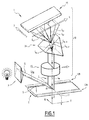
図1を参照すると、本発明の方法の各ステップを実施する装置1が説明されている。装置1は、スラグ部分5を流れ作業で取り扱うように適合されている。 With reference to FIG. 1, an apparatus 1 that implements each step of the method of the present invention is described. The device 1 is adapted to handle the slug portion 5 in an assembly line.
装置1は、光源7と、スラグ部分5からの光Lを集めるように調整された光学システム10と、スラグ部分5に隣接して配置される2つの参照標準エレメント12A、12Bと、場合により、スラグ部分に対して光学システムを動かすのに適したシフトデバイス(表されていない)とを備えている。
The apparatus 1 includes a light source 7, an
スラグ部分5は、例えば、電気アーク炉(EAF、表されていない)または取鍋炉(LF、表されていない)から採取したサンプルである。 The slag portion 5 is, for example, a sample taken from an electric arc furnace (EAF, not represented) or a boiler furnace (LF, not represented).
スラグ部分5は、決定されるべき化学組成を有する。 The slag portion 5 has a chemical composition to be determined.
スラグの物理的態様(色および厚み)は、その化学組成と関連する。例えば、FeOまたはMnOのような酸化物は、スラグに対して暗い態様を与え、一方、CaOまたはMgOのような酸化物は、スラグの厚みを増加する。 The physical aspect (color and thickness) of the slag is related to its chemical composition. For example, oxides such as FeO or MnO give a darker aspect to the slag, while oxides such as CaO or MgO increase the thickness of the slag.
スラグ部分5は、例えば互いに実質的に垂直の2つの軸X、Yに沿って延びる上側表面Sを有する。第3の軸Zは、軸Xおよび軸Yの両方に垂直な軸であるとも定義される。 The slug portion 5 has, for example, an upper surface S extending along two axes X, Y that are substantially perpendicular to each other. The third axis Z is also defined as an axis perpendicular to both the axis X and the axis Y.
表面Sは、例えば水平である。 The surface S is, for example, horizontal.
化学組成は、例えば、CaO、SiO2、MgO、Al2O3、S、Fe2O3、FeO、F、MnO、TiO2、Na2O、Cr2O3、Cl、BaO、SrO、P2O5、K2O、ZrO2、ZnO、CuOから採取された1つまたはいくつかの化合物のそれぞれの質量分率によって規定される。 The chemical composition is, for example, 1 collected from CaO, SiO2, MgO, Al2O3, S, Fe2O3, FeO, F, MnO, TiO2, Na2O, Cr2O3, Cl, BaO, SrO, P2O5, K2O, ZrO2, ZnO, CuO1 It is defined by the mass fraction of each of one or several compounds.
光源7は、光線Liをスラグ部分5に向かって送るように適合される。光源7は、例えば、LED(発光ダイオード)および/またはハロゲン球を含む。 The light source 7 is adapted to send a ray Li towards the slug portion 5. The light source 7 includes, for example, an LED (light emitting diode) and / or a halogen bulb.
2つの参照標準エレメント12A、12Bは、例えば、軸Xに沿って、スラグ部分5のそれぞれの側面に、有利には、軸Zに沿って表面Sと同じレベルに配置される。参照標準エレメント12A、12Bは、例えば、質量分率で少なくとも95%のステンレス鋼(例えばAISl 310)を含み、「AISI」は、「American Iron and Steel Institute」を意味している。
The two reference
変形例(表されていない)として、異なる数の参照標準エレメントが使用される。例えば、たった1個の、例えば、参照標準エレメント12Aが存在する。
As a variant (not shown), a different number of reference standard elements are used. For example, there is only one, eg, reference
シフトデバイスは、光学システム10を、例えば軸Yに沿って表面Sに対して動かすように調整される。
The shift device is adjusted to move the
光学システム10は、複数の点Mからの光Lの複数の部分LMを受け入れるのに適しており、複数の点Mの1つだけが図1に示されている。光学システム10は、少なくとも1つのCCDセンサまたはCMOSセンサ25と、少なくとも1つの分光器20と、少なくとも1つの光学レンズ15とを備えている。複数の点Mは、大部分が、表面Sおよび参照標準エレメント12A、12Bの上に配置されている。複数の点Mは、有利には、互いに規則的に空間が空けられている。2つのM点間の距離は、例えば、0.3〜1mm、例えば、0.5mmである。
The
それぞれの点Mは、例えば、第1の複数の空間座標x1、x2などから取られた軸Xに沿った第1の空間座標xと、第2の複数の空間座標y1、y2などから取られた軸Yに沿った第2の空間座標yによって規定される。言い換えると、第1の複数の空間座標x1、x2などと、第2の複数の空間座標y1、y2などは、複数の点Mの表示である。 Each point M is taken from, for example, the first spatial coordinate x along the axis X taken from the first plurality of spatial coordinates x1, x2, etc., and the second plurality of spatial coordinates y1, y2, etc. It is defined by the second spatial coordinate y along the axis Y. In other words, the first plurality of spatial coordinates x1, x2, etc., and the second plurality of spatial coordinates y1, y2, etc. are representations of a plurality of points M.
光Lは、例えば、軸Zに沿って表面Sによって反射する光である。表面Sは、光源7によって照らされる。他の実施形態(表されていない)において、光Lは、1本または複数本の光ファイバーケーブルによって伝わる。 The light L is, for example, light reflected by the surface S along the axis Z. The surface S is illuminated by the light source 7. In other embodiments (not represented), the light L is transmitted by one or more fiber optic cables.
セグメント27は、有利には、X軸に実質的に平行である。セグメント27は、同じ所与の第2の空間座標y(例えば、図1に示されるy1)を有する複数の点Mを含む。軸Yに沿った光学システム10の任意の移動により、センサ25は、有利には表面S全体をカバーするために、セグメント27に平行な連続したセグメントをスキャンするのに適している。
The
分光器20は、例えば、Specim V10_04204画像化分光器である。分光器20は、センサ25に衝突する部分LM,λ1、LM,λ2などを得るために、複数のスペクトルパラメータλ1、λ2などによって表される波長に基づき、点Mから来る光の一部分LMを分離することができる。有利には、分光器20は、センサ25に衝突する部分Lλ1、Lλ2などを直接的に得るために、セグメント27全体からの光Lを分離することができる。
The
それぞれの部分LM,λは、スペクトルパラメータλによって表される所与の波長で複数の点Mの1つから集められた光LMの一部分である。 Each portion L M, lambda is the portion of the light L M collected from one of a plurality of points M in a given wavelength, represented by spectral parameter lambda.
それぞれの部分Lλは、スペクトルパラメータλによって表される所与の波長で、セグメント27全体から集められた光Lの一部分である。それぞれの部分Lλは、セグメント27に属する複数の点Mからの部分LM,λを含む。
Each portion L λ is a portion of light L collected from the
スペクトルパラメータλは、説明した例におけるその波長そのものである。 The spectral parameter λ is the wavelength itself in the example described.
複数のスペクトルパラメータλ1、λ2などは、化学組成を決定するために使用される複数の波長の表示である。 The plurality of spectral parameters λ1, λ2, etc. are indications of a plurality of wavelengths used to determine the chemical composition.
有利には、複数のスペクトルパラメータλ1、λ2などは、399nm〜965nmの範囲の波長の表示である。例えば、複数のスペクトルパラメータλ1、λ2などは、399nm〜965nmに含まれる全ての波長の表示である。 Advantageously, the plurality of spectral parameters λ1, λ2 and the like are indications of wavelengths in the range of 399 nm to 965 nm. For example, a plurality of spectral parameters λ1, λ2, etc. are indications of all wavelengths included in 399 nm to 965 nm.
有利には、複数のスペクトルパラメータλ1、λ2などは、規則的に離間されており、例えば、1024個のスペクトルパラメータを含む。 Advantageously, the plurality of spectral parameters λ1, λ2, etc. are regularly spaced and include, for example, 1024 spectral parameters.
他の実施形態(表されていない)において、JAI−TM−1327GE CCDカメラおよびSpecim V10_04204画像化分光器以外の捕捉デバイスが使用される。 In other embodiments (not shown), capture devices other than the JAI-TM-1327GE CCD camera and the Specim V10_04204 imaging spectrometer are used.
他の実施形態(表されていない)において、他のハイパースペクトルカメラ、例えば、HySpex or HeadWallPhotonics分光器を上述のものの代わりに使用する。 In other embodiments (not shown), other hyperspectral cameras, such as HySpec or HeadWallPhotonics spectroscopes, are used in place of those described above.
センサ25は、光Lを捕捉するために適合されている。 The sensor 25 is adapted to capture the light L.
センサ25は、CCDセンサまたはCMOSセンサである。センサ25は、2D(二次元)センサ、例えば、IMX174LLJ CMOSセンサである。 The sensor 25 is a CCD sensor or a CMOS sensor. The sensor 25 is a 2D (two-dimensional) sensor, for example, an IMX174LLJ CMOS sensor.
センサ25は、光Lの部分LM,λを受け入れ、部分LM,λの強度の表示である値Ix,y,λを得るように適合される。 Sensor 25, part of the light L L M, receiving the lambda, part L M, a display of intensity of the lambda value I x, y, is adapted to obtain a lambda.
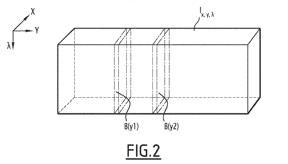
この例において、センサ25は、y1に等しい第2の空間座標を有する複数の点Mに対応する、セグメント27から来る光から得られた部分Lλを用い、データB(y1)のブロックを生成するように適合される(図2)。センサ25は、それぞれがy2などに等しい第2の空間座標を有する複数の点Mによって規定されるセグメントに対応するブロックB(y2)などを作成することができる。データB(y)のブロック全体で値Ix,y,λを与える。
In this example, the sensor 25 uses the portion L λ obtained from the light coming from the
値Ix,y,λは、三次元(3D)マトリックスΛx,y,λ(図2)を構成し、ここで、xは、第1の複数の空間座標x1、x2などの1つであり、yは、第2の複数の空間座標y1、y2などの1つであり、λは、複数のスペクトルパラメータλ1、λ2などの1つである。マトリックスΛx,y,λのそれぞれの値Ix,y,λは、例えば、グレースケール値である。 The values I x, y, λ constitute a three-dimensional (3D) matrix Λ x, y, λ (FIG. 2), where x is one of the first plurality of spatial coordinates x1, x2, and the like. Yes, y is one of the second plurality of spatial coordinates y1, y2, etc., and λ is one of the plurality of spectral parameters λ1, λ2, etc. The respective values I x, y, λ of the matrix Λ x, y, λ are, for example, grayscale values.
変形例として、セグメント27から出た光だけがセンサ25によって使用される。マトリックスΛx,y,λにおいて、y空間座標は、例えば、単純に除去される。この変形例において、マトリックスは、二次元マトリックスΛx,λである。
As a modification, only the light emitted from the
マトリックスΛx,λは、通常、<<ハイパースペクトルイメージ>>と呼ばれ、スペクトルパラメータλ1、λ2などによって表される種々の波長で取られたいくつかのイメージΛx,yが組み込まれている。 The matrix Λ x, λ is usually called << hyperspectral image >> and incorporates several images Λ x, y taken at various wavelengths represented by spectral parameters λ1, λ2, etc. ..
装置1は、スラグ部分5の化学組成を決定するためにマトリックスΛx,y,λを用いるのに適した少なくとも1つのコンピュータ(表されていない)も備えている。 The apparatus 1 also comprises at least one computer (not shown) suitable for using the matrix Λ x, y, λ to determine the chemical composition of the slag portion 5.
図1から図3を参照しつつ、本発明の方法100をここに説明する。方法100は、スラグ部分5の化学組成を決定することを目的とする。 The method 100 of the present invention will be described here with reference to FIGS. 1 to 3. Method 100 aims to determine the chemical composition of the slag moiety 5.
方法100は、例えば、プロセス中に鋼鉄に添加される添加剤の量を計算するために、スラグ部分5の化学組成が決定される鋼鉄製造プロセスの一部であることを意図している。 Method 100 is intended to be part of a steel manufacturing process in which the chemical composition of the slag portion 5 is determined, for example, to calculate the amount of additives added to the steel during the process.
実際に、スラグ部分5の化学組成に基づき、鋼鉄の化学組成を概算することができ、この組成が標的とする最終的な組成とは異なる場合、鋼鉄への添加剤注入のような必要な工程を行うことができる。 In fact, the chemical composition of the steel can be estimated based on the chemical composition of the slag portion 5, and if this composition differs from the final target composition, a necessary step such as injecting additives into the steel. It can be performed.
方法100は、三次元マトリックスΛx,y,λ(いわゆるハイパースペクトルイメージ)の形態でデータセットを与えるステップ110と、調整されたマトリックスを得るために、マトリックスを調整するステップ120と、化学組成を得るために、調整されたマトリックスを用いて数学アルゴリズムを行うステップ130とを含む。
Method 100 comprises
有利には、方法100は、さらに、調整するステップ120に有用な値を与えるためのキャリブレーションステップ104と、調整するステップ120およびアルゴリズム実施ステップ130で使用されるパラメータを決定するためのトレーニングステップ106とを含む。
Advantageously, the method 100 further comprises a
マトリックスΛx,y,λを与えるステップ110は、スラグ部分5を与えるサブステップと、光学システム10を用い、表面Sから反射した光Lを集めるサブステップと、集められた光Lからデータセットを得るサブステップと、を含み、このデータセットは、マトリックスΛx,y,λを少なくとも規定する。
Step 110 for giving the matrix Λ x, y, λ is a sub-step for giving the slug portion 5, a sub-step for collecting the light L reflected from the surface S using the
この例において、得られるデータセットは、マトリックスΛx,y,λそのものである。上に説明したように、光学システム10は、表面Sに対し、この表面の連続的なセグメントをスキャンするために、軸Yを沿って移動する。各セグメントについて、光学システム10は、データB(y)のブロックを与える。データB(y)のブロックは、全体でマトリックスΛx,y,λを構成する。
In this example, the resulting dataset is the matrix Λ x, y, λ itself. As described above, the
たった1つのセグメントからの光が光学システム10によって使用される特定の実施形態(表されていない)において、光学システムは、表面Sに対して移動しない。
In certain embodiments (not represented) where light from only one segment is used by the
調整するステップ120は、マトリックスΛx,y,λをセグメント化するサブステップと、このマトリックス中のそれぞれの値lx,y,λを正規化するサブステップと、分光シグネチャIsigλを得るために、この値を空間平滑化するサブステップと、分光シグネチャIsigλのサイズを縮小するサブステップとを含む。
The adjusting
セグメント化するサブステップにおいて、対応する複数の点Mがスラグ部分5に属するかどうかを決定するために、マトリックスΛx,y,λの値lx,y,λを分析する。スラグ部分5に属する複数の点Mに対応する値Ix,y,λのみが、マトリックスに保持される。 In sub-step of segmenting, M corresponding plurality of points in order to determine whether it belongs to the slug portion 5, the matrix lambda x, y, the value of lambda l x, y, analyzing lambda. Only the values I x, y, λ corresponding to the plurality of points M belonging to the slag portion 5 are held in the matrix.
値Ix,y,λは、例えば、黒い値から白い値までの急な遷移、また、その逆の白い値から黒い値までの急な遷移を検出するために、x=0からハイパースペクトルイメージの幅(すなわち、第1の空間座標xの最大値)まで分析される。この分析が、それぞれの第2の空間座標yについて行われる。有利には、1つの波長λにおけるマトリックスΛx,y,λの導函数を計算し、所定の閾値より大きな値を探す。これにより、ハイパースペクトルイメージ中のスラグ部分5の境界を検出することができる。 The values I x, y, λ are hyperspectral images from x = 0 to detect, for example, a sudden transition from a black value to a white value and vice versa. Is analyzed up to the width of (that is, the maximum value of the first spatial coordinate x). This analysis is performed for each second spatial coordinate y. Advantageously, the derivatives of the matrix Λ x, y, λ at one wavelength λ are calculated and a value larger than a predetermined threshold is searched for. Thereby, the boundary of the slag portion 5 in the hyperspectral image can be detected.
正規化するサブステップは、正規化された値Inormx,y,λを与え、この値は、反射した光Lを集めるステップの間のスラグ部分5の外からの照射の影響がない。これらの値Inormx,y,λは、マトリックスΛnormを構成する。 The normalizing substep gives the normalized values Inorm x, y, λ, which is unaffected by external irradiation of the slag portion 5 during the step of collecting the reflected light L. These values Inorm x, y, λ constitute the matrix Λnorm.
正規化は、例えば、以下の式またはなんらかの等価式に従って、暗色リファレンス値D(「暗色」)を引き算し、白色リファレンス値W(「白色」)を補正することによって行われる。 Normalization is performed, for example, by subtracting the dark reference value D (“dark”) and correcting the white reference value W (“white”) according to the following equation or some equivalent equation.
![]()
![]()
このキャリブレーションステップ104は、暗色リファレンス値Dおよび白色リファレンス値Wのセットを周期的に獲得するサブステップを含む。暗色リファレンス値Dは、光学レンズが覆われたときに捕捉される画像から得られる。白色リファレンス値Wは、
座標X12AおよびX12Bでの既知の位置にある参照標準エレメント12A、12Bの捕捉された画像から得られる。参照標準エレメント12Aおよび12Bの正確な位置のために、上に説明したもの以外の同様のセグメント化アルゴリズムが使用される。
The
Obtained from captured images of reference
このキャリブレーションステップは、鋼鉄を製造する作業の開始時に一度行われてもよく、または、好ましい実施形態において、リファレンス値をアップデートするために規則的に行われてもよい。 This calibration step may be performed once at the beginning of the work of manufacturing the steel, or in a preferred embodiment, it may be performed regularly to update the reference value.
この式を用いる正規化ステップによって、異なる位置xに沿って、および/または時間の中で強度が均一ではない照明システムの影響について、または、センサ25が受け入れる光に影響を与える環境的な照射のスペクトル応答の修正について、ハイパースペクトルイメージを補正することができる。 By the normalization step using this equation, for the effects of lighting systems that are not uniform in intensity along different positions x and / or over time, or for environmental irradiation that affects the light received by the sensor 25. The hyperspectral image can be corrected for correction of the spectral response.
空間平滑化のサブステップは、正規化された値Inormx,y,λを用い、分光シグネチャIsigλを与えるように適合される。分光シグネチャIsigλは、サンプル内のノイズおよび獲得偏差を吸収するため、スラグ部分5のより正確なスペクトル表示である。 The spatial smoothing substep is adapted to give the spectroscopic signature Isig λ using the normalized values Inorm x, y, λ. The spectral signature Isig λ is a more accurate spectral representation of the slug portion 5 because it absorbs noise and acquisition deviations within the sample.
空間平滑化技術は、マトリックスΛnorm内のスラグ部分5に適用される。この技術は、スラグ部分5全体にわたるそれぞれの波長での空間平均の計算である。この結果は、以下の式を用いた1つの分光シグネチャIsigλである: The space smoothing technique is applied to the slug portion 5 in the matrix Λnorm. This technique is the calculation of the spatial average at each wavelength over the entire slug portion 5. The result is one spectroscopic signature Isig λ using the following equation:
Nmaxx、Nminxは、X軸に沿ってスラグ部分5の境界を定め、マトリックスΛx,y,λセグメント化サブステップ中に計算される。
Nmax x and Nmin x demarcate the slag portion 5 along the X axis and are calculated during the matrix Λ x, y, λ segmentation substep.
サイズを縮小するサブステップの開始時に、完全な値のセットIcompを得るために、分光シグネチャIsigλは、有利には、追加のパラメータ、例えば、複数のスペクトルパラメータλ1、λ2などから誘導される比率または引き算によって完成されることができる。 At the beginning of the size reduction substep, in order to obtain the complete set of values Icomp, the spectroscopic signature Isig λ is advantageously a ratio derived from additional parameters, such as multiple spectral parameters λ1, λ2, etc. Or it can be completed by subtraction.
この例において、複数のスペクトルパラメータλ1、λ2などは、1024個の波長を表す。しかしながら、Hugues効果のため、数百の波長のスペクトルパラメータΩ(λ)のサブセットまで次元を減らすことが望ましい。有利には、保存されるスペクトルパラメータΩ(λ)のサブセットは、本明細書で下に説明するように、トレーニングステップ106のサブステップ中に決定される。計算器または任意の適合する方法の使用によって決定することもできる。 In this example, the plurality of spectral parameters λ1, λ2, etc. represent 1024 wavelengths. However, due to the Hugues effect, it is desirable to reduce the dimension to a subset of the spectral parameter Ω (λ) of hundreds of wavelengths. Advantageously, a subset of the conserved spectral parameters Ω (λ) are determined during the substeps of training step 106, as described below herein. It can also be determined by the use of a calculator or any suitable method.
トレーニングステップ106は、既知の組成を有する複数のスラグサンプルについて獲得した値のデータセットIcompを与えるサブステップと、2つの独立したサブステップ106Aおよび106Bを含む。サブステップ106Aは、サイズを縮小するステップにおいて保存されるスペクトルパラメータΩ(λ)のサブセットを与えることを目的とする。サブステップ106Bは、アルゴリズム実施ステップ130のためのパラメータを与えることを目的とし、以下に説明する。
Training step 106 includes a sub-step that provides a dataset Icomp of the values obtained for multiple slag samples with a known composition, and two
サブステップ106Aは、例えば、再帰的特徴量削減技術を使用し、関連する値を選択するために、完全な値のセットIcompからいくつかのエレメントを除去する。回帰アルゴリズムの実施パラメータは、例えば、本発明の方法の出力と、例えばトレーニングデータセットのサブセットから得られるスラグ部分5の化学組成との存在する最大相関として計算される。高い相関に達するトレーニングデータセットのサブセットは、サイズを縮小するステップで保存されるべきスペクトルパラメータΩ(λ)のサブセットを規定する。
次いで、完全な値のセットIcompからの値のサブセットは、トレーニングステップ106に基づいて選択され、選択されていない値は、シグネチャから除去される。選択されたサブセットの値は、複数のスペクトルパラメータλ1、λ2などから選択されるスペクトルパラメータΩ(λ)のサブセットによってインデックスを付けられ、前記スペクトルパラメータΩ(λ)のサブセットは、複数のスペクトルパラメータよりも小さい。これにより、縮小された値のセットIredを得るために、Icompのサイズを縮小することができる。 A subset of the values from the complete set of values Icomp are then selected based on training step 106 and the unselected values are removed from the signature. The value of the selected subset is indexed by a subset of the spectral parameters Ω (λ) selected from the plurality of spectral parameters λ1, λ2, etc., and the subset of the spectral parameter Ω (λ) is derived from the plurality of spectral parameters. Is also small. This allows the size of Icomp to be reduced in order to obtain a reduced set of values.
数学アルゴリズムを行うステップ130は、データ正規化のサブステップと、回帰のサブステップを含む。 Step 130 of performing the mathematical algorithm includes a data normalization substep and a regression substep.
データ正規化のサブステップは、Ired値の縮小された値のセットを所定の数値範囲内に正規化する。このサブステップは、異なるスケールで測定される値を、概念的に共通のスケールに変換する。これは、例えば、データセットの最小値の引き算および同じデータセットの最大値による割り算に基づくことができる。 The data normalization substep normalizes a reduced set of Ired values within a predetermined numerical range. This substep transforms values measured on different scales into a conceptually common scale. It can be based, for example, on subtracting the minimum value of a dataset and dividing by the maximum value of the same dataset.
回帰ステップは、リグレッサーによって行われ、上述の値のセットを、概算された化学組成値と数学的にマッピングする。回帰のサブステップは、例えば、サポートベクターマシンモデル(SVM)に基づく。SVMは、2つの異なるパラメータω(サポートベクトル)およびb(オフセット)を含み、これらはトレーニングステップ140のサブステップ106Bで決定される。このようなパラメータは、当業者には知られている。 The regression step is performed by a regressor and mathematically maps the above set of values to the estimated chemical composition values. The regression substeps are based, for example, on a Support Vector Machine Model (SVM). The SVM contains two different parameters ω (support vector) and b (offset), which are determined in substep 106B of training step 140. Such parameters are known to those of skill in the art.
化学組成は、例えば、縮小された値のセットIredとベクトルωを掛け算し、b値を加えることによって得られる。これは、化学組成の表示である数を与える。 The chemical composition is obtained, for example, by multiplying the reduced set of values Ired by the vector ω and adding the b value. This gives a number that is an indication of the chemical composition.
既に説明されたように、トレーニングステップ106は、既知の組成を有する複数のスラグサンプルについて獲得した値のデータセットIcompを与えるサブステップと、2つの独立したサブステップ106Aおよび106Bを含む。サイズを縮小するステップにおいて保存されるスペクトルパラメータΩ(λ)のサブセットを与えるサブステップ106Aは、既に説明されている。
As previously described, training step 106 includes a sub-step that provides a dataset Icomp of the values obtained for multiple slag samples with a known composition, and two
ステップ106Bは、ステップ130のための各スラグ化合物あたりのリグレッサーパラメータ(例えばωおよびb)を設定する。
Step 106B sets the regressor parameters (eg, ω and b) for each slag compound for
このサブステップ106Bは、SMVトレーニングのための既製の方法に基づく。 This sub-step 106B is based on a ready-made method for SMV training.
試験
この章は、実施された検証試験を含む。既知の組成を有するLFフラグで構成されるトレーニングデータセットは、例えば、2つのサブセットに分けられ、第1のサブセットは、リグレッサーパラメータを算出するために使用され、第2のサブセットは、システムの誤差および精度を概算するために使用される。誤差は、本発明の方法を用いて得られる組成値と、実際の組成値との差として得られる。組成値は、百分率として表される。
Testing This chapter contains verification tests conducted. A training dataset consisting of LF flags with a known composition is divided into, for example, two subsets, the first subset is used to calculate the regressor parameters and the second subset is of the system. Used to estimate error and accuracy. The error is obtained as the difference between the composition value obtained by using the method of the present invention and the actual composition value. The composition value is expressed as a percentage.
誤差値は、この報告において、以下のように与えられる。 The error values are given in this report as follows:
![]()
![]()
![]()
sは絶対誤差の標準偏差であり、
Mはトレーニングデータセットからの入力値の最大値であり、
mはトレーニングデータセットからの入力値の最小値である。
![]()
s is the standard deviation of the absolute error
M is the maximum value of the input value from the training dataset,
m is the minimum value of the input value from the training data set.
以下の表は、本発明を用い、スラグサンプルを用いて得られる結果 対 Perl技術によるXRF(蛍光X線)を用いて行われる同じスラグサンプルの実験的な分析をまとめている。 The table below summarizes the results obtained with slag samples using the present invention vs. experimental analysis of the same slag samples performed using XRF (X-ray fluorescence) by the Perl technique.
上述の特徴のおかげで、この方法は迅速であり、鋼鉄性増プロセスを妨害しない。 Thanks to the features mentioned above, this method is rapid and does not interfere with the steel increasing process.
この方法は、所定の鋼鉄化学組成を得るために、製造中に鋼鉄に添加されるべき添加剤の量を推測することを可能にする。 This method makes it possible to estimate the amount of additives to be added to the steel during production in order to obtain a given steel chemical composition.
この方法は、2〜3秒で正確な化学組成を与え、一方、従来技術の方法は、分析のためにサンプルを実験室に送る必要がある。 This method gives an accurate chemical composition in 2-3 seconds, while the prior art method requires sending the sample to the laboratory for analysis.
スラグ情報に基づく取鍋プロセスを最適化するために、スラグ分析システムは、プラントからのデータを通信し、受け入れ、そのため、取鍋処理の変化が、任意の時間で知られる(鋼鉄の組成、鋼鉄およびスラグの重量、添加剤、温度など)。これらのデータを、抽出されたスラグ組成についての情報と合わせ、任意の点でのグローバルマスバランスの分析を行うことができ、その結果、任意の特定の熱力学計算ソフトウェアを用いて熱力学的平衡の計算を行うことができ、最終的な鋼鉄およびスラグの組成を平衡条件で算出することができた。 To optimize the ladle process based on slag information, the slag analysis system communicates and accepts data from the plant, so changes in the ladle process are known at any time (steel composition, steel). And slag weight, additives, temperature, etc.). These data can be combined with information about the extracted slag composition to perform an analysis of global mass balance at any point, resulting in thermodynamic equilibrium using any particular thermodynamic calculation software. The final steel and slag composition could be calculated under equilibrium conditions.
これに加え、取鍋炉で使用される種々のフェロアロイおよびフラックス添加剤についての情報を、価格を含めて計算に導入することができる。本システムは、これらを簡単に設定することができるからである。これによって、取鍋炉におけるプロセスの完全な分析を行うことができた。 In addition, information about the various ferroalloys and flux additives used in the pan furnace can be incorporated into the calculation, including price. This is because this system can easily set these. This allowed a complete analysis of the process in the pan furnace.
Claims (13)
表面(S)を有するスラグ部分(5)を与えるステップと、
光学システム(10)を用い、表面(S)から反射した光(L)を集めるステップと、
集めた光(L)からデータセットを得るステップであって、このデータセットが値を含むマトリックス(Λ)を少なくとも規定し、値の各々が集めた光(L)の一部分(LM,λ)の強度の表示であり、それぞれの一部分(LM,λ)が、複数の波長の1つで表面(S)上の複数の点(M)の1つからそれぞれ集められ、マトリックス(Λ)は、
複数の点(M)の複数の空間座標(x1、x2など)、および
複数の波長の表示である複数のスペクトルパラメータ(λ1、λ2など)
によって少なくともインデックスを付けられる、ステップと、
得られたデータセットから縮小された値のセットを得るために、マトリックス(Λ)を調整する(120)ステップと、
化学組成を得るために、縮小された値のセットを用い、数学アルゴリズムを行う(130)ステップとを含み、
データセットを得るステップが、以下のサブステップ:
部分(LM,λ)の強度の表示であるグレースケール値を与えるサブステップと、
前記グレースケール値を用い、マトリックスに含まれる値(lx,y,λ)を得るサブステップとを含み、
調整するステップ(120)が、
反射した光(L)を集めるステップ中、スラグ部分(5)の外からの照射の影響がないように適合された正規化された値を得るために、マトリックス中のそれぞれの値を正規化するサブステップと、
スラグ部分(5)の分光シグネチャを得るために、正規化された値を空間平滑化するサブステップと、
縮小された値のセットを得るために、分光シグネチャにおける値のサブセットを選択するサブステップと
を含む、方法。 A method (100) for determining the chemical composition of the slag moiety (5), the method of which is:
The step of giving the slag portion (5) having the surface (S) and
A step of collecting the light (L) reflected from the surface (S) using the optical system (10), and
A step of obtaining a dataset from the collected light (L), where the dataset defines at least a matrix (Λ) containing the values, each of which is a portion of the collected light (L) (LM , λ ). Each part (LM , λ ) is collected from one of the plurality of points (M) on the surface (S) at one of the plurality of wavelengths, and the matrix (Λ) is ,
Multiple spatial coordinates (x1, x2, etc.) of multiple points (M), and multiple spectral parameters (λ1, λ2, etc.) that represent multiple wavelengths.
At least indexed by the steps and
To obtain a reduced set of values from the resulting dataset, the (120) step of adjusting the matrix (Λ), and
Including (130) steps of performing a mathematical algorithm using a reduced set of values to obtain the chemical composition.
The steps to get the dataset are as follows:
A substep that gives a grayscale value, which is an indication of the intensity of the part (LM , λ),
The grayscale value is used to include a substep to obtain the values (l x, y, λ) contained in the matrix.
The adjustment step (120) is
During the step of collecting the reflected light (L), each value in the matrix is normalized to obtain a normalized value adapted so that it is not affected by external irradiation of the slag portion (5). Substeps and
Substeps to spatially smooth the normalized values to obtain the spectroscopic signature of the slag portion (5),
To obtain a set of reduced values, and a salicylate Busuteppu select a subset of the values in the spectral signature method.
鋼鉄の標的とする化学組成を規定するステップと、
請求項1から12のいずれかに記載の鋼鉄を製造するプロセス中に作られたスラブ部分の化学組成を決定するステップと、
決定されたスラグ部分の化学組成を用い、鋼鉄の化学組成を概算するステップと、
概算された鋼鉄の化学組成を用い、添加剤の量を計算するステップと、
前記鋼鉄の標的とする化学組成に達するように、鋼鉄に前記添加剤を前記量で加えるステップと、
を含む、方法。 It ’s a way to make steel,
Steps to define the target chemical composition of steel,
The step of determining the chemical composition of the slab portion produced during the process of producing the steel according to any one of claims 1 to 12.
Steps to estimate the chemical composition of steel using the determined chemical composition of the slag portion,
Using the estimated chemical composition of steel, the steps to calculate the amount of additives,
The step of adding the additive to the steel in the amount so as to reach the target chemical composition of the steel.
Including methods.
Applications Claiming Priority (1)
| Application Number | Priority Date | Filing Date | Title |
|---|---|---|---|
| PCT/IB2015/053453 WO2016181185A1 (en) | 2015-05-11 | 2015-05-11 | Method of determining a chemical composition of a slag portion |
Publications (2)
| Publication Number | Publication Date |
|---|---|
| JP2018517903A JP2018517903A (en) | 2018-07-05 |
| JP6905939B2 true JP6905939B2 (en) | 2021-07-21 |
Family
ID=53433222
Family Applications (1)
| Application Number | Title | Priority Date | Filing Date |
|---|---|---|---|
| JP2017559405A Active JP6905939B2 (en) | 2015-05-11 | 2015-05-11 | How to determine the chemical composition of the slag moiety |
Country Status (12)
| Country | Link |
|---|---|
| US (1) | US10677736B2 (en) |
| EP (1) | EP3295154A1 (en) |
| JP (1) | JP6905939B2 (en) |
| KR (1) | KR102093005B1 (en) |
| CN (1) | CN107787442B (en) |
| AU (1) | AU2015394657B2 (en) |
| BR (1) | BR112017024334B1 (en) |
| CA (1) | CA2985941C (en) |
| MX (1) | MX2017014474A (en) |
| RU (1) | RU2683002C1 (en) |
| UA (1) | UA120449C2 (en) |
| WO (1) | WO2016181185A1 (en) |
Families Citing this family (4)
| Publication number | Priority date | Publication date | Assignee | Title |
|---|---|---|---|---|
| WO2019117200A1 (en) * | 2017-12-15 | 2019-06-20 | Jfeスチール株式会社 | Method for refining molten iron |
| CN111024228B (en) * | 2019-12-31 | 2022-08-23 | 杭州高谱成像技术有限公司 | High-spectrum camera radiation calibration device, method and system |
| BR112023016119A2 (en) | 2021-03-10 | 2023-10-03 | Arcelormittal | DEVICE FOR DETERMINING THE CHEMICAL COMPOSITION OF A LIQUID METALLURGICAL PRODUCT AND METHOD FOR DETERMINING THE CHEMICAL COMPOSITION OF A LIQUID METALLURGICAL PRODUCT |
| WO2023275385A1 (en) * | 2021-07-02 | 2023-01-05 | Noda Technologies Ab | A method for determining at least one property of an aluminium production bath in of an aluminium production cell, a system for determining the at least one property, and a probe for capturing a sample from the aluminium production cell |
Family Cites Families (16)
| Publication number | Priority date | Publication date | Assignee | Title |
|---|---|---|---|---|
| JP3861480B2 (en) * | 1998-11-12 | 2006-12-20 | Jfeスチール株式会社 | Slag analysis method and apparatus |
| JP2000227396A (en) * | 1999-02-05 | 2000-08-15 | Kawasaki Steel Corp | Method and device for determining basicity of slag |
| US7346205B2 (en) * | 2003-03-27 | 2008-03-18 | Bartron Medical Imaging, Llc | System and method for rapidly identifying pathogens, bacteria and abnormal cells |
| US6998614B2 (en) * | 2003-05-23 | 2006-02-14 | Institute For Technology Development | Hyperspectral imaging workstation having visible/near-infrared and ultraviolet image sensors |
| DE10339595A1 (en) * | 2003-08-26 | 2005-04-07 | Siemens Ag | Method for predicting and controlling the pourability of liquid steel |
| JP2005201636A (en) | 2004-01-13 | 2005-07-28 | Shizuoka Prefecture | Method and device for judging putrid part |
| DE102004044382A1 (en) * | 2004-09-11 | 2006-03-30 | Nowack, Norbert, Prof. Dr.-Ing. | Device for measuring degrees of reflection and reflection spectra on liquid and solidified iron metallurgy slag and casting powder comprises a waveguide which transfers a light beam onto a liquid or solid slag and/or casting powder |
| EP1862795A1 (en) * | 2006-05-10 | 2007-12-05 | ABB Schweiz AG | Bulk Material Analyzer System |
| US7924414B2 (en) * | 2006-05-10 | 2011-04-12 | Abb Schweiz Ag | Non-hazardous bulk material analyzer system |
| US8315692B2 (en) * | 2007-02-22 | 2012-11-20 | Sheinis Andrew I | Multi-spectral imaging spectrometer for early detection of skin cancer |
| WO2009142758A1 (en) * | 2008-05-23 | 2009-11-26 | Spectral Image, Inc. | Systems and methods for hyperspectral medical imaging |
| JP5197239B2 (en) | 2008-08-29 | 2013-05-15 | キヤノン株式会社 | Image processing apparatus, image processing method, and program |
| WO2011021128A2 (en) * | 2009-08-20 | 2011-02-24 | Koninklijke Philips Electronics N.V. | Method and system for image analysis |
| JP2012098181A (en) * | 2010-11-02 | 2012-05-24 | Sumitomo Electric Ind Ltd | Device and method for detection |
| BR112014009061A2 (en) * | 2011-10-13 | 2017-04-18 | Pioneer Hi Bred Int | Method to automatically discern between object pixels and non-object pixels Method to automatically discern between plant pixels and non-plant pixels in a hyperspectral image data cube |
| US9237279B2 (en) | 2013-05-06 | 2016-01-12 | Bergen Teknologioverfoering As | Method of investigating a solid sample |
-
2015
- 2015-05-11 BR BR112017024334-2A patent/BR112017024334B1/en active IP Right Grant
- 2015-05-11 JP JP2017559405A patent/JP6905939B2/en active Active
- 2015-05-11 CA CA2985941A patent/CA2985941C/en active Active
- 2015-05-11 RU RU2017142970A patent/RU2683002C1/en active
- 2015-05-11 EP EP15729935.5A patent/EP3295154A1/en active Pending
- 2015-05-11 UA UAA201711993A patent/UA120449C2/en unknown
- 2015-05-11 WO PCT/IB2015/053453 patent/WO2016181185A1/en active Application Filing
- 2015-05-11 MX MX2017014474A patent/MX2017014474A/en unknown
- 2015-05-11 KR KR1020177035148A patent/KR102093005B1/en active IP Right Grant
- 2015-05-11 AU AU2015394657A patent/AU2015394657B2/en active Active
- 2015-05-11 CN CN201580081162.5A patent/CN107787442B/en active Active
- 2015-05-11 US US15/573,440 patent/US10677736B2/en active Active
Also Published As
| Publication number | Publication date |
|---|---|
| CN107787442B (en) | 2020-11-03 |
| CN107787442A (en) | 2018-03-09 |
| CA2985941A1 (en) | 2016-11-17 |
| BR112017024334B1 (en) | 2021-03-02 |
| UA120449C2 (en) | 2019-12-10 |
| KR102093005B1 (en) | 2020-03-25 |
| EP3295154A1 (en) | 2018-03-21 |
| US20180120235A1 (en) | 2018-05-03 |
| MX2017014474A (en) | 2018-04-10 |
| AU2015394657B2 (en) | 2019-07-11 |
| AU2015394657A1 (en) | 2017-11-30 |
| RU2683002C1 (en) | 2019-03-25 |
| BR112017024334A2 (en) | 2018-07-24 |
| US10677736B2 (en) | 2020-06-09 |
| KR20180004234A (en) | 2018-01-10 |
| CA2985941C (en) | 2022-04-26 |
| WO2016181185A1 (en) | 2016-11-17 |
| JP2018517903A (en) | 2018-07-05 |
Similar Documents
| Publication | Publication Date | Title |
|---|---|---|
| JP6905939B2 (en) | How to determine the chemical composition of the slag moiety | |
| JP6687125B2 (en) | Method for evaluating slag volume on molten metal surface | |
| US10157461B2 (en) | Cell evaluation device, cell evaluation method, and cell evaluation program | |
| CN105160683B (en) | A kind of molten iron drossing measurement and control system and its method based on manual intervention | |
| JP6292187B2 (en) | Method for refining molten iron, composition analysis method for high-temperature substance, and composition analysis apparatus for high-temperature substance | |
| Strąkowski et al. | Estimation of FeO content in the steel slag using infrared imaging and artificial neural network | |
| JP2020063898A (en) | Slag amount measurement device and slag amount measurement method | |
| EP3795702B1 (en) | Melt component estimation device, melt component estimation method, and method for producing melt | |
| JP6119812B2 (en) | Method for analyzing slag composition and method for refining molten metal | |
| JP6699802B2 (en) | Furnace control method | |
| CN117611579B (en) | Ladle lining online detection method and online detection system | |
| CN111079537B (en) | Method, system, machine-readable medium and equipment for identifying smelting working conditions of converter | |
| JP2022167371A (en) | Dust generation speed evaluation device and dust generation speed evaluation method | |
| JP2022177624A (en) | Dust generation speed estimation device and dust generation speed estimation method | |
| JP2023549268A (en) | How to process cullet using colorimetric analysis | |
| JPH07270317A (en) | Analysis method for molten iron component | |
| CN106153553A (en) | Converter steel-smelting molten steel carbon content online Real-time and Dynamic Detection system | |
| Rådberg | Identifying, visualizing and quantifying process disturbances at SSAB Oxelösund using multivariate modelling | |
| CN106153552A (en) | Converter steel-smelting molten steel carbon content online Real-time and Dynamic Detection system | |
| JPH02170909A (en) | Method for predicting components at blow-end in converter |
Legal Events
| Date | Code | Title | Description |
|---|---|---|---|
| A621 | Written request for application examination |
Free format text: JAPANESE INTERMEDIATE CODE: A621 Effective date: 20180219 |
|
| A977 | Report on retrieval |
Free format text: JAPANESE INTERMEDIATE CODE: A971007 Effective date: 20181226 |
|
| A131 | Notification of reasons for refusal |
Free format text: JAPANESE INTERMEDIATE CODE: A131 Effective date: 20190108 |
|
| A601 | Written request for extension of time |
Free format text: JAPANESE INTERMEDIATE CODE: A601 Effective date: 20190402 |
|
| A521 | Request for written amendment filed |
Free format text: JAPANESE INTERMEDIATE CODE: A523 Effective date: 20190704 |
|
| A131 | Notification of reasons for refusal |
Free format text: JAPANESE INTERMEDIATE CODE: A131 Effective date: 20191112 |
|
| A601 | Written request for extension of time |
Free format text: JAPANESE INTERMEDIATE CODE: A601 Effective date: 20200206 |
|
| A521 | Request for written amendment filed |
Free format text: JAPANESE INTERMEDIATE CODE: A523 Effective date: 20200508 |
|
| A131 | Notification of reasons for refusal |
Free format text: JAPANESE INTERMEDIATE CODE: A131 Effective date: 20201006 |
|
| A521 | Request for written amendment filed |
Free format text: JAPANESE INTERMEDIATE CODE: A523 Effective date: 20210105 |
|
| A131 | Notification of reasons for refusal |
Free format text: JAPANESE INTERMEDIATE CODE: A131 Effective date: 20210309 |
|
| A521 | Request for written amendment filed |
Free format text: JAPANESE INTERMEDIATE CODE: A523 Effective date: 20210526 |
|
| TRDD | Decision of grant or rejection written | ||
| A01 | Written decision to grant a patent or to grant a registration (utility model) |
Free format text: JAPANESE INTERMEDIATE CODE: A01 Effective date: 20210615 |
|
| A61 | First payment of annual fees (during grant procedure) |
Free format text: JAPANESE INTERMEDIATE CODE: A61 Effective date: 20210628 |
|
| R150 | Certificate of patent or registration of utility model |
Ref document number: 6905939 Country of ref document: JP Free format text: JAPANESE INTERMEDIATE CODE: R150 |