JP6905910B2 - Diagnostic device and diagnostic method - Google Patents

Diagnostic device and diagnostic method Download PDF

Info

Publication number
JP6905910B2
JP6905910B2 JP2017198184A JP2017198184A JP6905910B2 JP 6905910 B2 JP6905910 B2 JP 6905910B2 JP 2017198184 A JP2017198184 A JP 2017198184A JP 2017198184 A JP2017198184 A JP 2017198184A JP 6905910 B2 JP6905910 B2 JP 6905910B2
Authority
JP
Japan
Prior art keywords
determination
concentration
reducing agent
aqueous solution
urea aqueous
Prior art date
Legal status (The legal status is an assumption and is not a legal conclusion. Google has not performed a legal analysis and makes no representation as to the accuracy of the status listed.)
Active
Application number
JP2017198184A
Other languages
Japanese (ja)
Other versions
JP2019073976A (en
Inventor
匡教 渡辺
匡教 渡辺
英志 中尾
英志 中尾
Current Assignee (The listed assignees may be inaccurate. Google has not performed a legal analysis and makes no representation or warranty as to the accuracy of the list.)
Bosch Corp
Original Assignee
Bosch Corp
Priority date (The priority date is an assumption and is not a legal conclusion. Google has not performed a legal analysis and makes no representation as to the accuracy of the date listed.)
Filing date
Publication date
Application filed by Bosch Corp filed Critical Bosch Corp
Priority to JP2017198184A priority Critical patent/JP6905910B2/en
Publication of JP2019073976A publication Critical patent/JP2019073976A/en
Application granted granted Critical
Publication of JP6905910B2 publication Critical patent/JP6905910B2/en
Active legal-status Critical Current
Anticipated expiration legal-status Critical

Links

Images

Classifications

    • YGENERAL TAGGING OF NEW TECHNOLOGICAL DEVELOPMENTS; GENERAL TAGGING OF CROSS-SECTIONAL TECHNOLOGIES SPANNING OVER SEVERAL SECTIONS OF THE IPC; TECHNICAL SUBJECTS COVERED BY FORMER USPC CROSS-REFERENCE ART COLLECTIONS [XRACs] AND DIGESTS
    • Y02TECHNOLOGIES OR APPLICATIONS FOR MITIGATION OR ADAPTATION AGAINST CLIMATE CHANGE
    • Y02ATECHNOLOGIES FOR ADAPTATION TO CLIMATE CHANGE
    • Y02A50/00TECHNOLOGIES FOR ADAPTATION TO CLIMATE CHANGE in human health protection, e.g. against extreme weather
    • Y02A50/20Air quality improvement or preservation, e.g. vehicle emission control or emission reduction by using catalytic converters

Description

本発明は、内燃機関の排気の浄化に用いられる液体還元剤の濃度を、濃度センサを用いて診断する診断装置及び診断方法に関する。 The present invention relates to a diagnostic apparatus and a diagnostic method for diagnosing the concentration of a liquid reducing agent used for purifying the exhaust gas of an internal combustion engine by using a concentration sensor.

車両に搭載されるディーゼルエンジン等の内燃機関の排気ガスに含まれるNOX(窒素酸化物)を分解して排気ガスを浄化するための装置として、尿素SCR(Selective Catalytic Reduction)システムが実用化されている。尿素SCRシステムでは、還元剤として尿素水溶液が用いられる。尿素SCRシステムは、尿素水溶液が分解することにより生成されるアンモニアを排気ガス中のNOXと反応させることによりNOXを分解する。 The urea SCR (Selective Catalytic Reduction) system has been put into practical use as a device for decomposing NO X (nitrogen oxides) contained in the exhaust gas of internal combustion engines such as diesel engines mounted on vehicles and purifying the exhaust gas. ing. In the urea SCR system, an aqueous urea solution is used as the reducing agent. Urea SCR systems degrades NO X by reacting ammonia produced by the urea aqueous solution is decomposed with NO X in the exhaust gas.

尿素SCRシステムは、排気通路に配設された選択還元触媒と、選択還元触媒よりも上流側の排気通路に尿素水溶液を噴射するための還元剤供給装置とを備える。選択還元触媒は、アンモニアを吸着し、流入する排気ガス中のNOXとアンモニアとの還元反応を促進する。還元剤供給装置は、貯蔵タンク内に貯蔵された尿素水溶液を圧送するポンプと、ポンプにより圧送される尿素水溶液を噴射する噴射弁とを備え、制御装置によって駆動制御が行われて、尿素水溶液を排気通路内に噴射する。 The urea SCR system includes a selective reduction catalyst disposed in the exhaust passage and a reducing agent supply device for injecting an aqueous urea solution into the exhaust passage on the upstream side of the selective reduction catalyst. The selective reduction catalyst adsorbs ammonia and promotes the reduction reaction between NO X and ammonia in the inflowing exhaust gas. The reducing agent supply device includes a pump for pumping the urea aqueous solution stored in the storage tank and an injection valve for injecting the urea aqueous solution pumped by the pump, and the drive control is performed by the control device to supply the urea aqueous solution. Inject into the exhaust passage.

制御装置は、内燃機関から排出されている排気ガスに含まれるNOXを浄化するために必要なアンモニア量と選択還元触媒に吸着可能なアンモニア量とに基づいて尿素水溶液の噴射量を算出する。尿素水溶液の噴射量が少なすぎると、NOXを適切に浄化することができない。また、尿素水溶液の噴射量が多すぎると、選択還元触媒の下流に流出(スリップ)するアンモニアが増えることになる。このため、尿素SCRシステムでは、あらかじめ定められた基準濃度の尿素水溶液が用いられ、制御装置は、必要なアンモニア量に見合った尿素水溶液の目標噴射量を設定し、噴射制御を実行する。 The control device calculates the injection amount of the urea aqueous solution based on the amount of ammonia required to purify NO X contained in the exhaust gas discharged from the internal combustion engine and the amount of ammonia adsorbable to the selective reduction catalyst. If the amount of the urea aqueous solution injected is too small, NO X cannot be properly purified. Further, if the amount of the urea aqueous solution injected is too large, the amount of ammonia that flows out (slip) downstream of the selective reduction catalyst increases. Therefore, in the urea SCR system, a urea aqueous solution having a predetermined reference concentration is used, and the control device sets a target injection amount of the urea aqueous solution corresponding to the required amount of ammonia and executes injection control.

このような尿素SCRシステムにおいて、尿素水溶液の濃度が基準濃度と異なると、噴射された尿素水溶液から生成されるアンモニアの量に過不足が生じることになる。このため、特許文献1に記載されているように、尿素水溶液が貯蔵される貯蔵タンクには濃度センサ(「クオリティセンサ」ともいう)が備えられ、尿素水溶液の濃度が基準濃度から大きくずれていないかの診断が行われている。 In such a urea SCR system, if the concentration of the urea aqueous solution is different from the reference concentration, the amount of ammonia produced from the injected urea aqueous solution will be excessive or insufficient. Therefore, as described in Patent Document 1, the storage tank in which the urea aqueous solution is stored is provided with a concentration sensor (also referred to as “quality sensor”), and the concentration of the urea aqueous solution does not deviate significantly from the reference concentration. Is being diagnosed.

特開2008−248710号公報Japanese Unexamined Patent Publication No. 2008-248710

ここで、尿素水溶液中に気泡が含まれる場合、当該気泡は、濃度センサによる尿素水溶液の濃度の検出の障害となり得るため、尿素水溶液中に気泡が含まれ得る状態における濃度センサの検出値の信頼性は低くなる。尿素水溶液中に気泡が含まれ得る状態においても適切な濃度の尿素水溶液の濃度が異常であると誤判定されないようにするには、診断時のずれの許容範囲を大きく設定しなければならない。しかしながら、診断時のずれの許容範囲を大きくすると、尿素水溶液の実際の濃度が基準濃度から大きくずれている場合であっても異常と判定されにくくなってしまう。 Here, when the urea aqueous solution contains bubbles, the bubbles can interfere with the detection of the concentration of the urea aqueous solution by the concentration sensor. Therefore, the reliability of the detection value of the concentration sensor in the state where the bubbles can be contained in the urea aqueous solution is reliable. The sex becomes low. In order to prevent erroneous determination that the concentration of the urea aqueous solution having an appropriate concentration is abnormal even in a state where bubbles may be contained in the urea aqueous solution, it is necessary to set a large allowable range of deviation at the time of diagnosis. However, if the permissible range of deviation at the time of diagnosis is increased, it becomes difficult to determine an abnormality even when the actual concentration of the urea aqueous solution deviates significantly from the reference concentration.

本発明は、上記問題に鑑みてなされたものであり、本発明の目的とするところは、濃度センサを用いた尿素水溶液の濃度の診断結果の信頼性を向上可能な診断装置及び診断方法を提供することにある。 The present invention has been made in view of the above problems, and an object of the present invention is to provide a diagnostic device and a diagnostic method capable of improving the reliability of the diagnostic result of the concentration of an aqueous urea solution using a concentration sensor. To do.

本発明のある観点によれば、車両に搭載された内燃機関の排気の浄化に用いられる液体還元剤の濃度を、液体還元剤を貯蔵するタンクに設置された濃度センサを用いて診断する診断装置において、濃度センサの検出値と液体還元剤の基準濃度とのずれが第1の閾値以下であるか否かを判定する第1の判定を実行する第1の判定部と、濃度センサの検出値と液体還元剤の基準濃度とのずれが第1の閾値よりも大きい第2の閾値以下であるか否かを判定する第2の判定を実行する第2の判定部と、を備え、第1の判定部は、診断装置の起動後に第1の判定を実行開始し、タンク内の液体還元剤中の気泡が増大する第1の条件が成立したときに第1の判定の実行を終了し、第2の判定部は、少なくとも第1の条件の成立後に第2の判定を実行する、診断装置が提供される。 According to a certain aspect of the present invention, a diagnostic device that diagnoses the concentration of a liquid reducing agent used for purifying the exhaust of an internal combustion engine mounted on a vehicle by using a concentration sensor installed in a tank that stores the liquid reducing agent. In the first determination unit for executing the first determination for determining whether or not the deviation between the detection value of the concentration sensor and the reference concentration of the liquid reducing agent is equal to or less than the first threshold value, and the detection value of the concentration sensor. A second determination unit for executing a second determination for determining whether or not the deviation between the liquid reducing agent and the reference concentration of the liquid reducing agent is equal to or less than the second threshold value larger than the first threshold value. The determination unit starts executing the first determination after the diagnostic device is activated, and ends the execution of the first determination when the first condition for increasing the number of bubbles in the liquid reducing agent in the tank is satisfied. The second determination unit is provided with a diagnostic device that executes the second determination after at least the first condition is satisfied.

また、本発明の別の観点によれば、車両に搭載された内燃機関の排気の浄化に用いられる液体還元剤の濃度を、液体還元剤を貯蔵するタンクに設置された濃度センサを用いて診断する診断方法において、診断装置の起動後からタンク内の液体還元剤中の気泡が増大する第1の条件が成立するまでの期間に、濃度センサの検出値と液体還元剤の基準濃度とのずれが第1の閾値以下であるか否かを判定する第1の判定を実行するとともに、診断装置の起動後、少なくとも第1の条件の成立後に、濃度センサの検出値と液体還元剤の基準濃度とのずれが第1の閾値よりも大きい第2の閾値以下であるか否かを判定する第2の判定を実行する、診断方法が提供される。 Further, according to another aspect of the present invention, the concentration of the liquid reducing agent used for purifying the exhaust of the internal combustion engine mounted on the vehicle is diagnosed by using the concentration sensor installed in the tank for storing the liquid reducing agent. In the diagnostic method to be performed, the deviation between the detection value of the concentration sensor and the reference concentration of the liquid reducing agent during the period from the start of the diagnostic device to the establishment of the first condition in which the bubbles in the liquid reducing agent in the tank increase. The detection value of the concentration sensor and the reference concentration of the liquid reducing agent are executed after the first determination is executed to determine whether or not is equal to or less than the first threshold value, and at least after the first condition is satisfied after the diagnostic device is started. A diagnostic method is provided that executes a second determination to determine whether or not the deviation from is greater than or equal to the first threshold and is less than or equal to the second threshold.

以上説明したように本発明によれば、濃度センサを用いた尿素水溶液の濃度の診断結果の信頼性を向上させることができる。 As described above, according to the present invention, it is possible to improve the reliability of the diagnostic result of the concentration of the urea aqueous solution using the concentration sensor.

本発明の実施の形態に係る診断装置を備えた適用可能な尿素SCRシステムを示す模式図である。It is a schematic diagram which shows the applicable urea SCR system provided with the diagnostic apparatus which concerns on embodiment of this invention. 同実施形態に係る診断装置の構成例を示すブロック図である。It is a block diagram which shows the structural example of the diagnostic apparatus which concerns on this embodiment. 尿素水溶液中に気泡が発生する一例を示す説明図である。It is explanatory drawing which shows an example which the bubble is generated in the urea aqueous solution. 第1の閾値及び第2の閾値を示す説明図である。It is explanatory drawing which shows the 1st threshold value and 2nd threshold value. 第1の判定及び第2の判定の実行期間を示す説明図である。It is explanatory drawing which shows the execution period of the 1st determination and the 2nd determination. 同実施形態に係る診断装置による診断処理を示すフローチャートである。It is a flowchart which shows the diagnostic process by the diagnostic apparatus which concerns on this embodiment. 診断処理の変形例を示すフローチャートである。It is a flowchart which shows the modification of the diagnosis process.

以下に添付図面を参照しながら、本発明の好適な実施の形態について詳細に説明する。なお、本明細書及び図面において、実質的に同一の機能構成を有する構成要素については、同一の符号を付することにより重複説明を省略する。 Hereinafter, preferred embodiments of the present invention will be described in detail with reference to the accompanying drawings. In the present specification and the drawings, components having substantially the same functional configuration are designated by the same reference numerals, so that duplicate description will be omitted.

<1.尿素SCRシステムの構成例>
図1を参照して、還元剤供給装置30を備えた尿素SCRシステム10の構成例について説明する。図1は、尿素SCRシステム10の構成例を示す模式図である。
<1. Configuration example of urea SCR system>
A configuration example of the urea SCR system 10 including the reducing agent supply device 30 will be described with reference to FIG. FIG. 1 is a schematic diagram showing a configuration example of the urea SCR system 10.

尿素SCRシステム10は、ディーゼルエンジン等の内燃機関5の排気系に設けられている。尿素SCRシステム10は、内燃機関5を備えた車両、建設機械又は農機等に搭載され、還元剤として尿素水溶液を用いて、内燃機関5から排出される排気ガス中のNOXを分解して排気を浄化する。尿素水溶液としては、例えば凍結温度が最も低い約32.5%濃度の尿素水溶液が用いられる。この場合の凍結温度は約−11℃である。かかる尿素水溶液は、濃度が変化すると凍結温度が上昇することから、溶媒としての水分が蒸発することによって凍結しやすくなる性質を有する。 The urea SCR system 10 is provided in the exhaust system of an internal combustion engine 5 such as a diesel engine. The urea SCR system 10 is mounted on a vehicle, a construction machine, an agricultural machine, or the like equipped with an internal combustion engine 5, and uses an aqueous urea solution as a reducing agent to decompose NO X in the exhaust gas discharged from the internal combustion engine 5 and exhaust it. Purify. As the urea aqueous solution, for example, a urea aqueous solution having the lowest freezing temperature of about 32.5% concentration is used. The freezing temperature in this case is about -11 ° C. Since the freezing temperature rises when the concentration of such an aqueous urea solution changes, it has a property of being easily frozen by evaporating water as a solvent.

尿素SCRシステム10は、排気管11の途中に配設された選択還元触媒13と、選択還元触媒13よりも上流の排気通路内に尿素水溶液を噴射する還元剤供給装置30とを備える。 The urea SCR system 10 includes a selective reduction catalyst 13 arranged in the middle of the exhaust pipe 11 and a reducing agent supply device 30 that injects an aqueous urea solution into an exhaust passage upstream of the selective reduction catalyst 13.

選択還元触媒13は、内燃機関5の排気ガス中に含まれるNOXを、アンモニアを用いて選択的に還元する。選択還元触媒13は、還元剤供給装置30により噴射された尿素水溶液が分解することにより生成されたアンモニアを吸着する。そして、選択還元触媒13は、流入する排気ガス中のNOXをアンモニアと反応させて分解する。選択還元触媒13は、触媒温度が高いほどアンモニアの吸着可能量が減少する性質を有する。また、選択還元触媒13は、吸着可能量に対する実際のアンモニアの吸着量の割合が大きいほどNOXの還元効率が高くなる性質を有する。 The selective reduction catalyst 13 selectively reduces NO X contained in the exhaust gas of the internal combustion engine 5 using ammonia. The selective reduction catalyst 13 adsorbs ammonia produced by the decomposition of the urea aqueous solution injected by the reducing agent supply device 30. Then, the selective reduction catalyst 13 reacts NO X in the inflowing exhaust gas with ammonia to decompose it. The selective reduction catalyst 13 has a property that the adsorbable amount of ammonia decreases as the catalyst temperature increases. Further, the selective reduction catalyst 13 has a property that the larger the ratio of the actual adsorbed amount of ammonia to the adsorbable amount, the higher the reducing efficiency of NO X.

還元剤供給装置30は、選択還元触媒13よりも上流の排気通路内に尿素水溶液を噴射する。還元剤供給装置30は、制御装置100によって駆動制御が行われる。尿素水溶液の噴射量は、選択還元触媒13よりも下流に流出するNOXの濃度及びアンモニアの濃度が基準値以下となるように制御される。尿素水溶液の噴射量は、例えば内燃機関5から排出される排気ガスのNOX濃度、選択還元触媒13の温度に応じたアンモニアの吸着可能量、及び選択還元触媒13上の現在のアンモニアの吸着量等に基づいて設定される。 The reducing agent supply device 30 injects an aqueous urea solution into the exhaust passage upstream of the selective reduction catalyst 13. The reducing agent supply device 30 is driven and controlled by the control device 100. The injection amount of the urea aqueous solution is controlled so that the concentration of NO X flowing downstream of the selective reduction catalyst 13 and the concentration of ammonia are equal to or less than the reference value. The injection amount of the urea aqueous solution is, for example, the NO X concentration of the exhaust gas discharged from the internal combustion engine 5, the adsorbable amount of ammonia according to the temperature of the selective reduction catalyst 13, and the current adsorption amount of ammonia on the selective reduction catalyst 13. Etc. are set based on.

選択還元触媒13よりも上流及び下流の排気管11には、それぞれの位置で排気温度を検出する排気温度センサ21,23が設けられている。排気温度センサ21,23のセンサ信号は制御装置100に出力される。排気温度センサ21,23によって検出される排気温度は、選択還元触媒13の温度推定にも用いられる。これ以外に、排気管11には、図示しないNOX濃度センサやアンモニアセンサ等が設けられていてもよい。 Exhaust pipes 11 upstream and downstream of the selective reduction catalyst 13 are provided with exhaust temperature sensors 21 and 23 that detect the exhaust temperature at their respective positions. The sensor signals of the exhaust temperature sensors 21 and 23 are output to the control device 100. The exhaust temperature detected by the exhaust temperature sensors 21 and 23 is also used for estimating the temperature of the selective reduction catalyst 13. In addition to this, the exhaust pipe 11 may be provided with a NO X concentration sensor, an ammonia sensor, or the like (not shown).

<2.還元剤供給装置の構成例>
次に、還元剤供給装置30の構成例について詳細に説明する。還元剤供給装置30は、噴射弁31とポンプ41とを備える。噴射弁31は、選択還元触媒13よりも上流の排気管11に固定されている。ポンプ41は、貯蔵タンク50内の尿素水溶液を吸い上げて圧送する。ポンプ41及び噴射弁31は、制御装置100によって駆動制御が行われる。
<2. Configuration example of reducing agent supply device>
Next, a configuration example of the reducing agent supply device 30 will be described in detail. The reducing agent supply device 30 includes an injection valve 31 and a pump 41. The injection valve 31 is fixed to the exhaust pipe 11 upstream of the selective reduction catalyst 13. The pump 41 sucks up the urea aqueous solution in the storage tank 50 and pumps it. The pump 41 and the injection valve 31 are driven and controlled by the control device 100.

ポンプ41の吸入口には、他端が貯蔵タンク50内に位置する第1の還元剤配管58が接続されている。ポンプ41の吐出口には、他端が噴射弁31に接続された第2の還元剤配管57が接続されている。ポンプ41は、第1の還元剤配管58を介して貯蔵タンク50内の尿素水溶液を吸い上げ、第2の還元剤配管57を介して尿素水溶液を噴射弁31に供給する。 A first reducing agent pipe 58 whose other end is located in the storage tank 50 is connected to the suction port of the pump 41. A second reducing agent pipe 57 whose other end is connected to the injection valve 31 is connected to the discharge port of the pump 41. The pump 41 sucks up the urea aqueous solution in the storage tank 50 through the first reducing agent pipe 58, and supplies the urea aqueous solution to the injection valve 31 through the second reducing agent pipe 57.

第2の還元剤配管57には、他端が貯蔵タンク50に接続されたリターン配管59が接続されている。リターン配管59には図示しないオリフィス又は一方向弁が備えられ、第2の還元剤配管57内の圧力を保持できるようになっている。また、第2の還元剤配管57には圧力センサ43が設けられている。圧力センサ43は、噴射弁31に供給される尿素水溶液の圧力Puを検出するセンサであり、センサ信号は制御装置100に出力される。 A return pipe 59 whose other end is connected to the storage tank 50 is connected to the second reducing agent pipe 57. The return pipe 59 is provided with an orifice or a one-way valve (not shown) so as to hold the pressure in the second reducing agent pipe 57. Further, the pressure sensor 43 is provided in the second reducing agent pipe 57. The pressure sensor 43 is a sensor that detects the pressure Pu of the urea aqueous solution supplied to the injection valve 31, and the sensor signal is output to the control device 100.

ポンプ41としては、例えば電磁駆動式のダイヤフラムポンプ又はギヤポンプが用いられる。ポンプ41の出力は、制御装置100により制御される。本実施形態では、制御装置100は、噴射弁31に供給される尿素水溶液の圧力Puが所定の目標値Ptgtで維持されるようにポンプ41の出力を制御する。例えば制御装置100は、圧力センサ43により検出される圧力Puと目標値Ptgtとの差分ΔPに基づいて、ポンプ41の出力をフィードバック制御する。 As the pump 41, for example, an electromagnetically driven diaphragm pump or a gear pump is used. The output of the pump 41 is controlled by the control device 100. In the present embodiment, the control device 100 controls the output of the pump 41 so that the pressure Pu of the urea aqueous solution supplied to the injection valve 31 is maintained at a predetermined target value Ptgt. For example, the control device 100 feedback-controls the output of the pump 41 based on the difference ΔP between the pressure Pu detected by the pressure sensor 43 and the target value Ptgt.

噴射弁31は、例えば通電制御により開弁及び閉弁が切り替えられる電磁駆動式の噴射弁が用いられる。電磁駆動式の噴射弁31は電磁コイルを備え、当該電磁コイルへの通電により発生する磁力によって弁体が移動して開弁する構造を有する。本実施形態では、制御装置100は、噴射弁31に供給される尿素水溶液の圧力Puが所定の目標値Ptgtとなるようにポンプ41の出力を制御しつつ、尿素水溶液の目標噴射量に応じて開弁時間を調節する。例えば制御装置100は、一定の噴射サイクルごとに、噴射サイクルの全時間に対する通電時間の比であるデューティ比を調節することにより、尿素水溶液の噴射量を制御する。 As the injection valve 31, for example, an electromagnetically driven injection valve whose opening and closing can be switched by energization control is used. The electromagnetically driven injection valve 31 includes an electromagnetic coil, and has a structure in which the valve body moves and opens due to the magnetic force generated by energizing the electromagnetic coil. In the present embodiment, the control device 100 controls the output of the pump 41 so that the pressure Pu of the urea aqueous solution supplied to the injection valve 31 becomes a predetermined target value Ptgt, and according to the target injection amount of the urea aqueous solution. Adjust the valve opening time. For example, the control device 100 controls the injection amount of the urea aqueous solution by adjusting the duty ratio, which is the ratio of the energization time to the total time of the injection cycle, for each constant injection cycle.

また、還元剤供給装置30は、装置内の尿素水溶液を貯蔵タンク50に回収する手段を備える。尿素水溶液の凍結温度は低くても−11℃程度であるため、内燃機関5の停止中に尿素水溶液が凍結する場合がある。装置内で尿素水溶液が凍結すると、体積が膨張して、それぞれの配管やポンプ41、噴射弁31等を破損させるおそれがある。このため、内燃機関5の停止時において、装置内の尿素水溶液は貯蔵タンク50に回収される。 Further, the reducing agent supply device 30 includes means for collecting the urea aqueous solution in the device in the storage tank 50. Since the freezing temperature of the urea aqueous solution is about -11 ° C. at the lowest, the urea aqueous solution may freeze while the internal combustion engine 5 is stopped. When the urea aqueous solution freezes in the apparatus, the volume expands, which may damage the respective pipes, the pump 41, the injection valve 31, and the like. Therefore, when the internal combustion engine 5 is stopped, the urea aqueous solution in the apparatus is recovered in the storage tank 50.

例えば、ポンプ41が逆回転可能なポンプである場合には当該ポンプ41が尿素水溶液の回収手段として用いられ、装置内の尿素水溶液を貯蔵タンク50側に吸い戻す。また、ポンプ41の吸入口及び吐出口の接続先を、第1の還元剤配管58又は第2の還元剤配管57に相互に切り換えることにより、ポンプ41の駆動による尿素水溶液の流れを反転させる流路切換弁が尿素水容液の回収手段として備えられてもよい。尿素水溶液の回収手段は、ここに例示した手段以外であってもよい。 For example, when the pump 41 is a pump that can rotate in the reverse direction, the pump 41 is used as a means for recovering the urea aqueous solution, and the urea aqueous solution in the apparatus is sucked back to the storage tank 50 side. Further, by switching the connection destinations of the suction port and the discharge port of the pump 41 to the first reducing agent pipe 58 or the second reducing agent pipe 57, the flow of the urea aqueous solution driven by the pump 41 is reversed. A path switching valve may be provided as a means for recovering the urea aqueous solution. The means for recovering the aqueous urea solution may be other than the means exemplified here.

尿素水溶液を貯蔵する貯蔵タンク50には、尿素水溶液の凍結時において凍結した尿素水溶液を解凍するための解凍手段が備えられる。例えば、解凍手段は、電熱線やPTC(Positive Temperature Coefficient)ヒータ等の電気式の加熱装置であってもよい。あるいは、貯蔵タンク50に内燃機関5の冷却水を循環させる冷却水配管を配設し、当該冷却水配管に内燃機関5の冷却水を循環させることにより貯蔵タンク50内の尿素水溶液を解凍させるようにしてもよい。 The storage tank 50 for storing the urea aqueous solution is provided with a thawing means for thawing the frozen urea aqueous solution when the urea aqueous solution is frozen. For example, the thawing means may be an electric heating device such as a heating wire or a PTC (Positive Temperature Coefficient) heater. Alternatively, a cooling water pipe for circulating the cooling water of the internal combustion engine 5 is provided in the storage tank 50, and the cooling water of the internal combustion engine 5 is circulated in the cooling water pipe to thaw the urea aqueous solution in the storage tank 50. It may be.

また、貯蔵タンク50には、貯蔵タンク50内の尿素水溶液の濃度を検出する濃度センサ51、及び貯蔵タンク50内の尿素水溶液の温度を検出するタンク温度センサ53が備えられている。濃度センサ51及びタンク温度センサ53のセンサ信号は、制御装置100に出力される。濃度センサ51としては、例えば超音波式センサ、熱伝達式センサ、又は赤外線式センサ等の公知の尿素水濃度センサが用いられる。それぞれの濃度センサ51は、尿素水溶液中に気泡が含まれていると検出値に誤差が生じる場合がある。 Further, the storage tank 50 is provided with a concentration sensor 51 for detecting the concentration of the urea aqueous solution in the storage tank 50 and a tank temperature sensor 53 for detecting the temperature of the urea aqueous solution in the storage tank 50. The sensor signals of the concentration sensor 51 and the tank temperature sensor 53 are output to the control device 100. As the concentration sensor 51, for example, a known urea water concentration sensor such as an ultrasonic sensor, a heat transfer type sensor, or an infrared type sensor is used. Each concentration sensor 51 may have an error in the detected value if bubbles are contained in the urea aqueous solution.

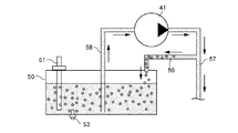
図3は、濃度センサ51が設置された貯蔵タンク50内の尿素水溶液中に気泡が発生する場合の一例を示す説明図である。上述のとおり、本実施形態に係る還元剤供給装置30では、内燃機関5の停止時に、装置内の尿素水溶液が貯蔵タンク50内に回収される。このため、内燃機関5の始動時には、まずポンプ41を駆動することにより、装置内に尿素水溶液が充填される。 FIG. 3 is an explanatory diagram showing an example of a case where bubbles are generated in the urea aqueous solution in the storage tank 50 in which the concentration sensor 51 is installed. As described above, in the reducing agent supply device 30 according to the present embodiment, when the internal combustion engine 5 is stopped, the urea aqueous solution in the device is recovered in the storage tank 50. Therefore, when the internal combustion engine 5 is started, the urea aqueous solution is filled in the apparatus by first driving the pump 41.

このとき、装置内は空気で満たされた状態で尿素水溶液の充填が行われるため、尿素水溶液が第2の還元剤配管57に供給されると、空気の一部が尿素水溶液とともにリターン配管59を介して貯蔵タンク50内に流れ込む。これにより、貯蔵タンク50内の尿素水溶液中に気泡が混入することになり、当該気泡が濃度センサ51による濃度検出の障害となり得る。かかる例以外にも、例えば内燃機関5の回転数が高い場合や車速が大きい場合等、車両の振動に起因して貯蔵タンク50内の尿素水溶液が揺動し、尿素水溶液中に気泡が発生する場合がある。 At this time, since the urea aqueous solution is filled while the inside of the apparatus is filled with air, when the urea aqueous solution is supplied to the second reducing agent pipe 57, a part of the air is connected to the return pipe 59 together with the urea aqueous solution. It flows into the storage tank 50 through the storage tank 50. As a result, air bubbles are mixed in the urea aqueous solution in the storage tank 50, and the air bubbles can interfere with the concentration detection by the concentration sensor 51. In addition to these examples, for example, when the rotation speed of the internal combustion engine 5 is high or the vehicle speed is high, the urea aqueous solution in the storage tank 50 fluctuates due to the vibration of the vehicle, and bubbles are generated in the urea aqueous solution. In some cases.

<3.制御装置(診断装置)の構成例>
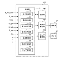
次に、本実施形態に係る尿素水溶液の濃度の診断装置として機能する制御装置100の構成例について説明する。図2は、制御装置100の構成を機能的に示したブロック図である。
<3. Configuration example of control device (diagnostic device)>
Next, a configuration example of the control device 100 that functions as a diagnostic device for the concentration of the urea aqueous solution according to the present embodiment will be described. FIG. 2 is a block diagram functionally showing the configuration of the control device 100.

制御装置100は、処理部110と、記憶部140と、噴射弁駆動部150と、ポンプ駆動部160とを備える。処理部110は、例えばCPU等のマイクロコンピュータ又はマイクロプロセッサユニット等で構成されていてもよく、ファームウェア等の更新可能なもので構成されていてもよい。また、処理部110は、CPU等からの指令によって実行されるプログラムモジュール等であってもよい。 The control device 100 includes a processing unit 110, a storage unit 140, an injection valve drive unit 150, and a pump drive unit 160. The processing unit 110 may be composed of, for example, a microcomputer such as a CPU, a microprocessor unit, or the like, or may be configured by an updatable one such as firmware. Further, the processing unit 110 may be a program module or the like executed by a command from a CPU or the like.

制御装置100には、濃度センサ51のセンサ信号S_cu、タンク温度センサ53のセンサ信号S_tu、圧力センサ43のセンサ信号S_pu及び排気温度センサ21,23のセンサ信号S_tgu,S_tgdが入力される。また、制御装置100には、直接あるいはCAN(Controller Area Network)等の通信手段を介して、車両のキースイッチのオンオフ信号S_key_swt、エンジン回転数Ne及び車速V等の内燃機関5の運転状態に関する情報が入力される。 The sensor signal S_cu of the concentration sensor 51, the sensor signal S_tu of the tank temperature sensor 53, the sensor signal S_pu of the pressure sensor 43, and the sensor signals S_tgu and S_tgd of the exhaust temperature sensors 21 and 23 are input to the control device 100. Further, the control device 100 is provided with information on the operating state of the internal combustion engine 5 such as the on / off signal S_key_swt of the key switch of the vehicle, the engine speed Ne, and the vehicle speed V, directly or via a communication means such as CAN (Controller Area Network). Is entered.

記憶部140は、RAM(Random Access Memory)やROM(Read Only Memory)等の図示しない記憶素子を含む。記憶部140は、CD−ROMやストレージ装置等のその他の記憶媒体を備えてもよい。記憶部140は、処理部110により実行されるプログラム、演算処理に用いられる各種パラメータ、演算結果及び検出結果等を記憶する。 The storage unit 140 includes a storage element (not shown) such as a RAM (Random Access Memory) and a ROM (Read Only Memory). The storage unit 140 may include other storage media such as a CD-ROM and a storage device. The storage unit 140 stores a program executed by the processing unit 110, various parameters used in the arithmetic processing, an arithmetic result, a detection result, and the like.

噴射弁駆動部150及びポンプ駆動部160は、電気回路により構成される。噴射弁駆動部150は、処理部110からの駆動指示の信号に基づいて動作し、噴射弁31を駆動する。ポンプ駆動部160は、処理部110からの駆動指示の信号に基づいて動作し、ポンプ41を駆動する。 The injection valve drive unit 150 and the pump drive unit 160 are composed of an electric circuit. The injection valve drive unit 150 operates based on a drive instruction signal from the processing unit 110 to drive the injection valve 31. The pump drive unit 160 operates based on a drive instruction signal from the processing unit 110 to drive the pump 41.

処理部110は、圧力検出部112と、濃度検出部114と、第1の判定部115と、第2の判定部116と、解凍制御部118と、噴射弁制御部120と、ポンプ制御部122とを有する。これらの各部は、処理部110がプログラムを実行することにより実現される機能である。 The processing unit 110 includes a pressure detection unit 112, a concentration detection unit 114, a first determination unit 115, a second determination unit 116, a defrost control unit 118, an injection valve control unit 120, and a pump control unit 122. And have. Each of these units is a function realized by the processing unit 110 executing a program.

圧力検出部112は、圧力センサ43のセンサ信号S_puに基づいて噴射弁31に供給される尿素水溶液の圧力Puを検出する。 The pressure detection unit 112 detects the pressure Pu of the urea aqueous solution supplied to the injection valve 31 based on the sensor signal S_pu of the pressure sensor 43.

濃度検出部114は、濃度センサ51のセンサ信号S_cuに基づいて貯蔵タンク50内の尿素水溶液の濃度(以下、「検出濃度」ともいう。)C_uを検出する。 The concentration detection unit 114 detects the concentration (hereinafter, also referred to as “detection concentration”) C_u of the urea aqueous solution in the storage tank 50 based on the sensor signal S_cu of the concentration sensor 51.

解凍制御部118は、タンク温度センサ53のセンサ信号S_tuに基づいて検出される貯蔵タンク50内の尿素水溶液の温度Tuが解凍制御の実行の要否を判定する基準温度以下の場合に解凍制御を実行する。凍結した尿素水溶液の解凍は、図示しない解凍手段を作動させることにより行われる。例えば、解凍制御部118は、貯蔵タンク50に設置された加熱装置を作動させて、凍結した尿素水溶液を解凍する。あるいは、解凍制御部118は、貯蔵タンク50に配設された冷却水配管に内燃機関5の冷却水を循環させて、凍結した尿素水溶液を解凍する。 The thawing control unit 118 performs thawing control when the temperature Tu of the urea aqueous solution in the storage tank 50 detected based on the sensor signal S_tu of the tank temperature sensor 53 is equal to or lower than the reference temperature for determining the necessity of executing the thawing control. Execute. The frozen urea aqueous solution is thawed by operating a thaw means (not shown). For example, the thawing control unit 118 operates a heating device installed in the storage tank 50 to thaw the frozen urea aqueous solution. Alternatively, the thawing control unit 118 circulates the cooling water of the internal combustion engine 5 through the cooling water pipe arranged in the storage tank 50 to thaw the frozen urea aqueous solution.

解凍制御部118は、例えば貯蔵タンク50内の尿素水溶液の温度Tuが上記の基準温度を超えた場合に解凍制御を終了してもよい。あるいは、解凍制御部118は、あらかじめ設定された時間が経過したときに解凍制御を終了してもよい。 The thawing control unit 118 may end the thawing control when, for example, the temperature Tu of the urea aqueous solution in the storage tank 50 exceeds the above-mentioned reference temperature. Alternatively, the decompression control unit 118 may end the decompression control when a preset time has elapsed.

ポンプ制御部122は、ポンプ41の出力を制御する。ポンプ制御部122は、圧力検出部112で検出される圧力Puが、あらかじめ設定された目標値Ptgtとなるように、ポンプ41の出力をフィードバック制御する。例えばポンプ制御部122は、検出された圧力Puと目標値Ptgtとの差分ΔPに基づいてポンプ41の出力をPID制御する。噴射弁31からの尿素水溶液の噴射量が多いほど尿素水溶液の圧力Puは低下しやすいことから、尿素水溶液の噴射量が多いほどポンプ41の出力は大きくなる。 The pump control unit 122 controls the output of the pump 41. The pump control unit 122 feedback-controls the output of the pump 41 so that the pressure Pu detected by the pressure detection unit 112 becomes a preset target value Ptgt. For example, the pump control unit 122 PID controls the output of the pump 41 based on the difference ΔP between the detected pressure Pu and the target value Ptgt. Since the pressure Pu of the urea aqueous solution tends to decrease as the injection amount of the urea aqueous solution from the injection valve 31 increases, the output of the pump 41 increases as the injection amount of the urea aqueous solution increases.

例えばポンプ制御部122は、一定の処理サイクルごとに、処理サイクルの全時間に対する通電時間の比であるデューティ比を設定する。この場合、デューティ比が大きいほどポンプ41の出力は大きくなる。ポンプ制御部122は、設定したデューティ比に基づいてポンプ駆動部160に対して駆動指示の信号を出力する。ポンプ駆動部160は、入力された駆動指示の信号に従ってポンプ41に対する通電を行う。 For example, the pump control unit 122 sets the duty ratio, which is the ratio of the energization time to the total time of the processing cycle, for each fixed processing cycle. In this case, the larger the duty ratio, the larger the output of the pump 41. The pump control unit 122 outputs a drive instruction signal to the pump drive unit 160 based on the set duty ratio. The pump drive unit 160 energizes the pump 41 according to the input drive instruction signal.

噴射弁制御部120は、噴射弁31の駆動制御を行う。上述のとおり、噴射弁31に供給される尿素水溶液の圧力Puは目標値Ptgtとなるように制御されているため、噴射弁制御部120は、尿素水溶液の圧力Puが目標値Ptgtとなっていることを前提として、噴射量の指示値に応じて噴射弁31の開弁時間を制御する。 The injection valve control unit 120 controls the drive of the injection valve 31. As described above, since the pressure Pu of the urea aqueous solution supplied to the injection valve 31 is controlled to be the target value Ptgt, the injection valve control unit 120 has the pressure Pu of the urea aqueous solution set to the target value Ptgt. On the premise of this, the valve opening time of the injection valve 31 is controlled according to the indicated value of the injection amount.

例えば、噴射弁制御部120は、内燃機関5から排出されている排気ガス中のNOXを還元するために必要なアンモニア量を求める。排気ガス中のNOXの量としては、例えば内燃機関5の運転状態に基づき推定されるNOX濃度又はNOXセンサにより検出されるNOX濃度に、排気ガスの流量を乗じて求められるNOX流量が用いられる。 For example, the injection valve control unit 120 obtains the amount of ammonia required to reduce NO X in the exhaust gas discharged from the internal combustion engine 5. The amount of the NO X in the exhaust gas, for example, the NO X concentration detected by the NO X concentration or NO X sensor is estimated based on the operating state of the internal combustion engine 5, NO X obtained by multiplying the flow rate of the exhaust gas The flow rate is used.

また、噴射弁制御部120は、選択還元触媒13におけるアンモニアの目標吸着量に対する過不足のアンモニア量を求める。選択還元触媒13におけるアンモニアの目標吸着量としては、例えば排気温度Tgasに基づいて推定される選択還元触媒13の温度に応じた吸着可能量に対して目標吸着率を乗じた値が用いられる。目標吸着率は、例えば70〜80%であってもよい。目標吸着率が70〜80%であれば、吸着率が比較的高く維持されてNOXの還元効率が高く維持される一方、触媒温度が急激に上昇した場合であっても、アンモニアの吸着可能量が実際のアンモニアの吸着量を下回りにくくなる。噴射弁制御部120は、積算により求められる現在のアンモニア吸着量と目標吸着量との差分に基づいて過不足のアンモニア量を求める。 Further, the injection valve control unit 120 obtains an excess or deficiency of ammonia with respect to the target adsorption amount of ammonia in the selective reduction catalyst 13. As the target adsorption amount of ammonia in the selective reduction catalyst 13, for example, a value obtained by multiplying the adsorbable amount according to the temperature of the selective reduction catalyst 13 estimated based on the exhaust temperature Tgas by the target adsorption rate is used. The target adsorption rate may be, for example, 70 to 80%. If the target adsorption rate is 70 to 80%, the adsorption rate is maintained relatively high and the NO X reduction efficiency is maintained high, while ammonia can be adsorbed even when the catalyst temperature rises sharply. The amount is less likely to fall below the actual amount of ammonia adsorbed. The injection valve control unit 120 obtains an excess or deficiency of ammonia amount based on the difference between the current ammonia adsorption amount and the target adsorption amount obtained by integration.

噴射弁制御部120は、排気ガス中のNOXを還元するために必要なアンモニア量と選択還元触媒13の目標吸着量に対する過不足のアンモニア量とを加算する。噴射弁制御部120は、算出されたアンモニア量を生成可能な尿素水溶液の量を目標噴射量とし、噴射弁駆動部150に対して駆動指示の信号を出力する。噴射弁駆動部150は、入力された駆動指示の信号に従って噴射弁31に対する通電を行う。例えば、噴射弁制御部120は、一定の噴射サイクルごとに、噴射サイクルの全時間に対する通電時間の比であるデューティ比を目標噴射量に基づいて設定する。噴射弁駆動部150は、設定されたデューティ比にしたがって噴射弁31の電磁コイルへの通電のオンオフを切り換える。 The injection valve control unit 120 adds the amount of ammonia required to reduce NO X in the exhaust gas and the amount of ammonia in excess or deficiency with respect to the target adsorption amount of the selective reduction catalyst 13. The injection valve control unit 120 sets a target injection amount as the amount of the urea aqueous solution capable of generating the calculated amount of ammonia, and outputs a drive instruction signal to the injection valve drive unit 150. The injection valve drive unit 150 energizes the injection valve 31 according to the input drive instruction signal. For example, the injection valve control unit 120 sets a duty ratio, which is the ratio of the energization time to the total time of the injection cycle, based on the target injection amount for each constant injection cycle. The injection valve drive unit 150 switches the energization of the injection valve 31 to the electromagnetic coil on and off according to the set duty ratio.

第1の判定部115は、尿素水溶液の濃度についての第1の判定を実行する。具体的に、第1の判定部115は、濃度検出部114により検出された尿素水溶液の検出濃度C_uと基準濃度C0とのずれが第1の閾値thre_A以下であるか否かを判定する。本実施形態において、尿素水溶液の基準濃度C0は32.5%である。判定に用いる尿素水溶液の検出濃度C_uは、所定期間内に検出された検出濃度C_uの平均値であってもよい。第1の判定部115は、制御装置100の起動後に第1の判定を実行開始し、貯蔵タンク50内の尿素水溶液中の気泡が増大する条件(第1の条件)が成立したときに第1の判定の実行を終了する。 The first determination unit 115 executes the first determination regarding the concentration of the aqueous urea solution. Specifically, the first determination unit 115 determines whether or not the deviation between the detection concentration C_u of the urea aqueous solution detected by the concentration detection unit 114 and the reference concentration C0 is equal to or less than the first threshold value thre_A. In the present embodiment, the reference concentration C0 of the urea aqueous solution is 32.5%. The detection concentration C_u of the urea aqueous solution used for the determination may be an average value of the detection concentrations C_u detected within a predetermined period. The first determination unit 115 starts executing the first determination after the control device 100 is activated, and when the condition for increasing the number of bubbles in the urea aqueous solution in the storage tank 50 (first condition) is satisfied, the first determination unit 115 is executed. Ends the execution of the judgment of.

第2の判定部116は、尿素水溶液の濃度についての第2の判定を実行する。具体的に、第2の判定部116は、濃度検出部114により検出された尿素水溶液の検出濃度C_uと基準濃度C0とのずれが、第1の閾値thre_Aよりも大きい第2の閾値thre_B以下であるか否かを判定する。第1の判定と同様に、判定に用いる尿素水溶液の検出濃度C_uは、所定期間内に検出された検出濃度C_uの平均値であってもよい。第2の判定部116は、少なくとも第1の条件の成立後に第2の判定を実行する。つまり、第2の判定は、少なくとも第1の判定の実行が終了した後に実行される。例えば、第2の判定部116は、制御装置100の起動後に第2の判定を実行開始し、第1の条件の成立後も第2の判定を継続してもよい。 The second determination unit 116 executes a second determination regarding the concentration of the aqueous urea solution. Specifically, in the second determination unit 116, the deviation between the detection concentration C_u of the urea aqueous solution detected by the concentration detection unit 114 and the reference concentration C0 is greater than the first threshold value thre_A and equal to or less than the second threshold value thre_B. Determine if it exists. Similar to the first determination, the detection concentration C_u of the urea aqueous solution used for the determination may be an average value of the detection concentrations C_u detected within a predetermined period. The second determination unit 116 executes the second determination after at least the first condition is satisfied. That is, the second determination is executed after at least the execution of the first determination is completed. For example, the second determination unit 116 may start executing the second determination after the control device 100 is activated, and may continue the second determination even after the first condition is satisfied.

ここで、第1の判定部115による第1の判定、及び、第2の判定部116による第2の判定について説明する。図4は、第1の判定及び第2の判定でそれぞれ用いられる第1の閾値thre_A及び第2の閾値thre_Bを示す説明図である。第2の判定で用いられる検出濃度C_uと基準濃度C0とのずれ(|C_u−C0|)の許容範囲である第2の閾値thre_Bは、第1の判定で用いられる検出濃度C_uと基準濃度C0とのずれ(|C_u−C0|)の許容範囲である第1の閾値thre_Aよりも大きい値に設定されている。尿素水溶液の基準濃度C0が32.5%である場合、第1の閾値thre_Aは例えば2.5%程度に設定され、第2の閾値thre_Bは例えば10.0%に設定される。 Here, the first determination by the first determination unit 115 and the second determination by the second determination unit 116 will be described. FIG. 4 is an explanatory diagram showing a first threshold value thre_A and a second threshold value thre_B used in the first determination and the second determination, respectively. The second threshold value thre_B, which is the allowable range of the deviation (| C_u-C0 |) between the detection concentration C_u and the reference concentration C0 used in the second determination, is the detection concentration C_u and the reference concentration C0 used in the first determination. It is set to a value larger than the first threshold value thre_A, which is an allowable range of deviation from (| C_u-C0 |). When the reference concentration C0 of the urea aqueous solution is 32.5%, the first threshold value thr_A is set to, for example, about 2.5%, and the second threshold value thre_B is set to, for example, 10.0%.

第1の判定部115による第1の判定は、尿素水溶液中の気泡が少ない期間に行われるため、第1の判定の実行中に濃度センサ51により検出される検出濃度C_uの信頼性は高いと言える。このため、第1の閾値thre_Aは相対的に小さい値に設定され、第1の判定では、尿素水溶液の実際の濃度が基準濃度C0に近似しているかが診断される。例えば、第1の判定によって異常が検出された場合には、排気ガス中のNOXに応じて尿素水溶液を過不足なく供給することが困難であるために、エンジンの出力を制限したり、エンジンの始動を停止したりしてもよい。 Since the first determination by the first determination unit 115 is performed during the period when there are few bubbles in the urea aqueous solution, the reliability of the detection concentration C_u detected by the concentration sensor 51 during the execution of the first determination is high. I can say. Therefore, the first threshold value thr_A is set to a relatively small value, and in the first determination, it is diagnosed whether the actual concentration of the urea aqueous solution is close to the reference concentration C0. For example, when an abnormality is detected by the first determination, it is difficult to supply an aqueous urea solution in just proportion according to NO X in the exhaust gas, so that the output of the engine is limited or the engine is used. You may stop the start of.

一方、第2の判定部116による第2の判定は、尿素水溶液中に気泡が発生し得る期間を含む期間に行われるため、第2の判定の実行中に濃度センサ51により検出される検出濃度C_uの信頼性は低いと言える。このため、第2の閾値thre_Bは相対的に大きい値に設定され、第2の判定では、尿素水溶液の実際の濃度が基準濃度C0に近似しているにもかかわらず誤って異常と判定されることを抑制する。例えば、第2の判定によって異常が検出された場合には、尿素水溶液の濃度の異常ではない、意図しない尿素水溶液の状態変化の場合も考えられるため、運転者等の搭乗者への警告等の措置に留めてもよい。 On the other hand, since the second determination by the second determination unit 116 is performed during the period including the period during which bubbles can be generated in the urea aqueous solution, the detection concentration detected by the concentration sensor 51 during the execution of the second determination is performed. It can be said that the reliability of C_u is low. Therefore, the second threshold value thr_B is set to a relatively large value, and in the second determination, it is erroneously determined to be abnormal even though the actual concentration of the urea aqueous solution is close to the reference concentration C0. Suppress that. For example, if an abnormality is detected by the second determination, it is possible that the concentration of the urea aqueous solution is not abnormal and the state of the urea aqueous solution is unintentionally changed. It may be limited to measures.

図5は、第1の判定部115による第1の判定、及び、第2の判定部116による第2の判定の実行期間を示す説明図である。図5に示した例では、制御装置(診断装置)100が起動したときに第1の判定及び第2の判定のいずれもが実行開始される。制御装置100の起動後、例えば貯蔵タンク50内の尿素水溶液の解凍制御が完了するまで、あるいは、触媒温度が上昇して選択還元触媒13が活性化するまで、還元剤供給装置30内への尿素水溶液の充填は開始されない。このため、貯蔵タンク50内の尿素水溶液中の気泡が少ない状態となっている。 FIG. 5 is an explanatory diagram showing an execution period of the first determination by the first determination unit 115 and the second determination by the second determination unit 116. In the example shown in FIG. 5, when the control device (diagnostic device) 100 is activated, both the first determination and the second determination are started to be executed. Urea into the reducing agent supply device 30 after the start of the control device 100, for example, until the thawing control of the urea aqueous solution in the storage tank 50 is completed, or until the catalyst temperature rises and the selective reduction catalyst 13 is activated. Filling of the aqueous solution is not started. Therefore, there are few bubbles in the urea aqueous solution in the storage tank 50.

したがって、貯蔵タンク50内の尿素水溶液中の気泡が増大し得る第1の条件が成立するまでの期間には第2の判定だけでなく第1の判定も併せて実行される。これにより、尿素水溶液の濃度の異常が検知される確実性が向上し、内燃機関の出力制限等の比較的厳しい措置を取ることができる。一方、第1の条件が成立した後は、貯蔵タンク50内の尿素水溶液中に気泡が含まれ得ることから、第1の判定は行われず、第2の判定のみが継続される。これにより、尿素水溶液の濃度が異常な状態になっていると断定できない場合には、警告等の比較的緩い措置に留めることができる。 Therefore, not only the second determination but also the first determination is executed in the period until the first condition that the bubbles in the urea aqueous solution in the storage tank 50 can increase is satisfied. As a result, the certainty that an abnormality in the concentration of the urea aqueous solution is detected is improved, and relatively strict measures such as output limitation of the internal combustion engine can be taken. On the other hand, after the first condition is satisfied, air bubbles may be contained in the urea aqueous solution in the storage tank 50, so that the first determination is not performed and only the second determination is continued. As a result, when it cannot be determined that the concentration of the urea aqueous solution is in an abnormal state, it is possible to limit the measures to relatively loose measures such as warning.

ここで、尿素水溶液中に気泡が発生し得る第1の条件は、還元剤供給装置30の始動であってもよい。図3に示したように、還元剤供給装置30のポンプ41の駆動が開始されて尿素水溶液が還元剤供給装置30に充填され始めると、装置内を満たしていた空気が尿素水溶液とともにリターン配管59を介して貯蔵タンク50に混入して、貯蔵タンク50内の尿素水溶液中に気泡が発生する。また、第1の条件は、車両の走行開始であってもよい。還元剤供給装置30が始動される前であっても、車両の走行が開始されると、加速時の揺れや内燃機関5の振動等の外乱によって尿素水溶液中に気泡が発生する場合がある。この他、第1の条件は、尿素水溶液中に気泡が発生し得る適宜の条件を含んでもよい。そして、第1の判定部115は、これらの第1の条件のうちのいずれか一つが成立したときに、第1の判定の実行を終了する。 Here, the first condition in which bubbles can be generated in the urea aqueous solution may be the start of the reducing agent supply device 30. As shown in FIG. 3, when the driving of the pump 41 of the reducing agent supply device 30 is started and the urea aqueous solution starts to be filled in the reducing agent supply device 30, the air filling the device is returned together with the urea aqueous solution 59. It is mixed into the storage tank 50 via the above, and bubbles are generated in the urea aqueous solution in the storage tank 50. Further, the first condition may be the start of traveling of the vehicle. Even before the reducing agent supply device 30 is started, when the vehicle starts running, bubbles may be generated in the urea aqueous solution due to disturbances such as shaking during acceleration and vibration of the internal combustion engine 5. In addition, the first condition may include an appropriate condition in which bubbles may be generated in the urea aqueous solution. Then, the first determination unit 115 ends the execution of the first determination when any one of these first conditions is satisfied.

<4.フローチャート>
次に、図6を参照して、制御装置(診断装置)100により実行される尿素水溶液の濃度の診断方法の例について説明する。
<4. Flowchart>
Next, with reference to FIG. 6, an example of a method for diagnosing the concentration of the urea aqueous solution executed by the control device (diagnosis device) 100 will be described.

まず、制御装置100が起動すると(ステップS11)、処理部110の第1の判定部115及び第2の判定部116は、尿素水溶液の解凍制御が完了したか否かを判別する(ステップS13)。処理部110の解凍制御部118は、尿素水溶液が凍結している場合に解凍制御を実行し、凍結した尿素水溶液が解凍したと判定される場合に解凍制御を終了し、解凍制御の完了を記憶部140に記憶する。解凍制御部118は、解凍制御を要しない場合においても解凍制御の完了を記憶部140に記憶する。 First, when the control device 100 is activated (step S11), the first determination unit 115 and the second determination unit 116 of the processing unit 110 determine whether or not the thawing control of the urea aqueous solution is completed (step S13). .. The thawing control unit 118 of the processing unit 110 executes thawing control when the urea aqueous solution is frozen, ends the thawing control when it is determined that the frozen urea aqueous solution has been thawed, and stores the completion of the thawing control. Store in unit 140. The defrost control unit 118 stores the completion of the defrost control in the storage unit 140 even when the defrost control is not required.

第1の判定部115及び第2の判定部116は、尿素水溶液の解凍制御が完了していない場合(S13/No)、尿素水溶液の解凍制御が完了するまでステップS13の判定を繰り返す。第1の判定部115及び第2の判定部116は、尿素水溶液の解凍制御が完了していた場合(S13/Yes)、それぞれ第1の判定及び第2の判定を開始する(ステップS15)。 When the thawing control of the urea aqueous solution is not completed (S13 / No), the first determination unit 115 and the second determination unit 116 repeat the determination in step S13 until the thawing control of the urea aqueous solution is completed. When the thawing control of the urea aqueous solution is completed (S13 / Yes), the first determination unit 115 and the second determination unit 116 start the first determination and the second determination, respectively (step S15).

次いで、第1の判定部115は、検出濃度C_uと基準濃度C0とのずれ(|C_u−C0|)が第1の閾値thre_A以下であるか否かを判別する(ステップS17)。検出濃度C_uと基準濃度C0とのずれ(|C_u−C0|)が第1の閾値thre_Aを超えている場合(S17/No)、第1の判定部115は、尿素水溶液の濃度の異常有りと判定する(ステップS33)。一方、検出濃度C_uと基準濃度C0とのずれ(|C_u−C0|)が第1の閾値thre_A以下の場合(S17/Yes)、第1の判定部115は、尿素水溶液の濃度の異常無しと判定する(ステップS19)。 Next, the first determination unit 115 determines whether or not the deviation (| C_u-C0 |) between the detected concentration C_u and the reference concentration C0 is equal to or less than the first threshold value thre_A (step S17). When the deviation between the detected concentration C_u and the reference concentration C0 (| C_u-C0 |) exceeds the first threshold value thre_A (S17 / No), the first determination unit 115 indicates that the concentration of the urea aqueous solution is abnormal. Determine (step S33). On the other hand, when the deviation between the detected concentration C_u and the reference concentration C0 (| C_u-C0 |) is equal to or less than the first threshold value thre_A (S17 / Yes), the first determination unit 115 indicates that there is no abnormality in the concentration of the urea aqueous solution. Determine (step S19).

次いで、第1の判定部115は、貯蔵タンク50内の尿素水溶液中に気泡が増大する条件(第1の条件)が成立しているか否かを判別する(ステップS21)。例えば、第1の判定部115は、還元剤供給装置30が始動されたこと、及び車両の走行が開始されたこと等、あらかじめ設定された条件のうちのいずれかの条件が成立しているか否かを判別する。第1の条件が成立していない場合(S21/No)、第1の判定部115は、ステップS17に戻って第1の判定を繰り返す。一方、第1の条件が成立している場合(S21/Yes)、第1の判定部115は、第1の判定の実行を終了する(ステップS23)。 Next, the first determination unit 115 determines whether or not the condition for increasing bubbles (first condition) in the urea aqueous solution in the storage tank 50 is satisfied (step S21). For example, the first determination unit 115 determines whether or not any of the preset conditions such as the reduction agent supply device 30 has been started and the vehicle has started running is satisfied. To determine. When the first condition is not satisfied (S21 / No), the first determination unit 115 returns to step S17 and repeats the first determination. On the other hand, when the first condition is satisfied (S21 / Yes), the first determination unit 115 ends the execution of the first determination (step S23).

次いで、第2の判定部116は、検出濃度C_uと基準濃度C0とのずれ(|C_u−C0|)が第2の閾値thre_B以下であるか否かを判別する(ステップS25)。検出濃度C_uと基準濃度C0とのずれ(|C_u−C0|)が第2の閾値thre_Bを超えている場合(S25/No)、第2の判定部116は、尿素水溶液の濃度の異常有りと判定する(ステップS33)。一方、検出濃度C_uと基準濃度C0とのずれ(|C_u−C0|)が第2の閾値thre_B以下の場合(S25/Yes)、第2の判定部116は、尿素水溶液の濃度の異常無しと判定する(ステップS27)。 Next, the second determination unit 116 determines whether or not the deviation (| C_u-C0 |) between the detected concentration C_u and the reference concentration C0 is equal to or less than the second threshold value thre_B (step S25). When the deviation between the detected concentration C_u and the reference concentration C0 (| C_u-C0 |) exceeds the second threshold value thre_B (S25 / No), the second determination unit 116 indicates that the concentration of the urea aqueous solution is abnormal. Determine (step S33). On the other hand, when the deviation between the detected concentration C_u and the reference concentration C0 (| C_u-C0 |) is equal to or less than the second threshold value thre_B (S25 / Yes), the second determination unit 116 indicates that there is no abnormality in the concentration of the urea aqueous solution. Judgment (step S27).

次いで、第2の判定部116は、第2の判定を開始してからの経過時間Tがあらかじめ設定した閾値T1に到達したか否かを判別する(ステップS29)。この閾値T1は、第2の判定の終了時期を設定するものであり、例えば30分に設定される。経過時間Tは、診断装置100が起動してからの経過時間であってもよいし、還元剤供給装置30を始動させてからの経過時間であってもよい。 Next, the second determination unit 116 determines whether or not the elapsed time T from the start of the second determination has reached the preset threshold value T1 (step S29). This threshold value T1 sets the end time of the second determination, and is set to, for example, 30 minutes. The elapsed time T may be the elapsed time after the diagnostic device 100 is started, or the elapsed time after the reducing agent supply device 30 is started.

経過時間Tが閾値T1に到達していない場合(S29/No)、第2の判定部116は、ステップS25に戻って第2の判定を繰り返す。一方、経過時間Tが閾値T1に到達していた場合(S29/Yes)、第2の判定部116は、第2の判定の実行を終了する(ステップS31)。 When the elapsed time T has not reached the threshold value T1 (S29 / No), the second determination unit 116 returns to step S25 and repeats the second determination. On the other hand, when the elapsed time T has reached the threshold value T1 (S29 / Yes), the second determination unit 116 ends the execution of the second determination (step S31).

なお、ステップS33において尿素水溶液の濃度の異常有りと判定された場合、制御装置100は、第1の判定による異常又は第2の判定による異常に応じて、適宜の処理を実行する。例えば、第1の判定結果が異常を示した場合(S17/No)、排気ガス中のNOXに対応する適切な量の尿素水溶液を供給することが困難であるために、制御装置100は、排気ガス中のNOX濃度が低減するように、内燃機関の出力を制限させたり内燃機関の始動を停止させたりしてもよい。一方、第2の判定結果が異常を示した場合(S25/No)、制御装置100は、運転者等の搭乗者に対して尿素水溶液の濃度の異常を知らせるための警告処理を実行させてもよい。例えば、制御装置100は、警告音の発生、警告ランプの点灯、又は警告表示の少なくとも一つの処理を実行させてもよい。 When it is determined in step S33 that there is an abnormality in the concentration of the urea aqueous solution, the control device 100 executes an appropriate process according to the abnormality due to the first determination or the abnormality due to the second determination. For example, when the first determination result shows an abnormality (S17 / No), it is difficult to supply an appropriate amount of urea aqueous solution corresponding to NO X in the exhaust gas, so that the control device 100 has a control device 100. The output of the internal combustion engine may be limited or the start of the internal combustion engine may be stopped so that the NO X concentration in the exhaust gas is reduced. On the other hand, when the second determination result shows an abnormality (S25 / No), the control device 100 may execute a warning process for notifying a passenger such as a driver of the abnormality in the concentration of the urea aqueous solution. good. For example, the control device 100 may execute at least one process of generating a warning sound, lighting a warning lamp, or displaying a warning.

図6のフローチャートに基づいて説明した尿素水溶液の濃度の診断方法では、制御装置100の起動後に第1の条件が成立した時点で第1の判定の実行を終了させた。ただし、第1の判定部115は、第1の判定の実行を一旦終了させた後であっても、貯蔵タンク50内の尿素水溶液中の気泡が少ない状態において、第1の判定を再開させてもよい。図7は、第1の判定の実行を終了させた後に第1の判定を再開させる例を示すフローチャートである。 In the method for diagnosing the concentration of the aqueous urea solution described based on the flowchart of FIG. 6, the execution of the first determination is terminated when the first condition is satisfied after the control device 100 is started. However, the first determination unit 115 restarts the first determination even after the execution of the first determination is once completed in a state where there are few bubbles in the urea aqueous solution in the storage tank 50. It is also good. FIG. 7 is a flowchart showing an example in which the first determination is restarted after the execution of the first determination is completed.

第1の判定の実行が終了した後、第1の判定部115は、貯蔵タンク50内の尿素水溶液中の気泡が少ない状態と推定される第2の条件が成立しているか否かを判別する(ステップS41)。第2の条件は、例えば還元剤供給装置30のポンプ41の駆動を開始してから所定時間以上経過しており、内燃機関5の回転数Neが所定の閾値以下であり、かつ、車速Vが所定の閾値以下であることとすることができる。 After the execution of the first determination is completed, the first determination unit 115 determines whether or not the second condition presumed to be a state in which there are few bubbles in the urea aqueous solution in the storage tank 50 is satisfied. (Step S41). The second condition is, for example, that a predetermined time or more has passed since the start of driving the pump 41 of the reducing agent supply device 30, the rotation speed Ne of the internal combustion engine 5 is equal to or less than a predetermined threshold value, and the vehicle speed V is high. It can be less than or equal to a predetermined threshold.

ポンプ41の駆動を開始した後、時間の経過に伴って、停車中に装置内に満たされていた空気が装置外に排出され、かつ、貯蔵タンク50内に発生した気泡が消滅する。このため、ポンプ41の駆動を開始してから所定時間以上経過していることが第2の条件の一つとされる。また、内燃機関5の回転数Neが低い状態、かつ、車速Vが低い状態においては、貯蔵タンク50内の尿素水溶液の揺動が小さく、尿素水溶液中に気泡が生じにくい。このため、内燃機関5の回転数Neが所定の閾値以下であり、かつ、車速Vが所定の閾値以下であることが第2の条件に含まれる。この他、第2の条件は適宜設定されてもよい。 After starting the driving of the pump 41, with the passage of time, the air filled in the device while the vehicle is stopped is discharged to the outside of the device, and the air bubbles generated in the storage tank 50 disappear. Therefore, one of the second conditions is that a predetermined time or more has passed since the operation of the pump 41 was started. Further, when the rotation speed Ne of the internal combustion engine 5 is low and the vehicle speed V is low, the fluctuation of the urea aqueous solution in the storage tank 50 is small, and bubbles are unlikely to be generated in the urea aqueous solution. Therefore, the second condition includes that the rotation speed Ne of the internal combustion engine 5 is equal to or less than a predetermined threshold value and the vehicle speed V is equal to or less than a predetermined threshold value. In addition, the second condition may be set as appropriate.

第2の条件が成立していない場合(S41/No)、第1の判定部115は、第2の条件が成立するまでステップS41の判定を繰り返す。一方、第2の条件が成立している場合(S41/Yes)、第1の判定部115は、第1の判定の実行を再開する(ステップS43)。 When the second condition is not satisfied (S41 / No), the first determination unit 115 repeats the determination in step S41 until the second condition is satisfied. On the other hand, when the second condition is satisfied (S41 / Yes), the first determination unit 115 resumes the execution of the first determination (step S43).

次いで、第1の判定部115は、検出濃度C_uと基準濃度C0とのずれ(|C_u−C0|)が第1の閾値thre_A以下であるか否かを判別する(ステップS45)。検出濃度C_uと基準濃度C0とのずれ(|C_u−C0|)が第1の閾値thre_Aを超えている場合(S45/No)、第1の判定部115は、尿素水溶液の濃度の異常有りと判定する(ステップS49)。一方、検出濃度C_uと基準濃度C0とのずれ(|C_u−C0|)が第1の閾値thre_A以下の場合(S45/Yes)、第1の判定部115は、尿素水溶液の濃度の異常無しと判定する(ステップS47)。尿素水溶液の濃度に異常が見られない場合、第1の判定部115は、ステップS41に戻り、第2の条件が成立している間、第1の判定を繰り返す。 Next, the first determination unit 115 determines whether or not the deviation (| C_u-C0 |) between the detected concentration C_u and the reference concentration C0 is equal to or less than the first threshold value thre_A (step S45). When the deviation between the detected concentration C_u and the reference concentration C0 (| C_u-C0 |) exceeds the first threshold value thre_A (S45 / No), the first determination unit 115 indicates that the concentration of the urea aqueous solution is abnormal. Determine (step S49). On the other hand, when the deviation between the detected concentration C_u and the reference concentration C0 (| C_u-C0 |) is equal to or less than the first threshold value thre_A (S45 / Yes), the first determination unit 115 indicates that there is no abnormality in the concentration of the urea aqueous solution. Judgment (step S47). If no abnormality is found in the concentration of the urea aqueous solution, the first determination unit 115 returns to step S41 and repeats the first determination while the second condition is satisfied.

図7に示したように、第1の判定部115が、第1の判定の実行を一旦終了させた後であっても、貯蔵タンク50内の尿素水溶液中の気泡が少なくなる第2の条件が成立している間は第1の判定を実行することにより、尿素水溶液の濃度をより精度よく診断することができる。 As shown in FIG. 7, the second condition that the number of bubbles in the urea aqueous solution in the storage tank 50 is reduced even after the first determination unit 115 once finishes the execution of the first determination. By executing the first determination while the above is satisfied, the concentration of the urea aqueous solution can be diagnosed more accurately.

以上説明したように、本実施形態に係る還元剤供給装置30の制御装置(診断装置)100は、貯蔵タンク50内の尿素水溶液中の気泡が少ない状態においては、濃度センサ51の検出濃度C_uと基準濃度C0とのずれ(|C_u−C0|)の閾値として相対的に小さい第1の閾値thre_Aを用いて第1の判定を実行する。また、本実施形態に係る制御装置100は、貯蔵タンク50内の尿素水溶液中の気泡が増大し得る状態においては、濃度センサ51の検出濃度C_uと基準濃度C0とのずれ(|C_u−C0|)の閾値として相対的に大きい第2の閾値thre_Bを用いて第2の判定を実行する。 As described above, the control device (diagnosis device) 100 of the reducing agent supply device 30 according to the present embodiment has a detection concentration C_u of the concentration sensor 51 in a state where there are few bubbles in the urea aqueous solution in the storage tank 50. The first determination is performed using the relatively small first threshold value thre_A as the threshold value of the deviation (| C_u-C0 |) from the reference concentration C0. Further, in the control device 100 according to the present embodiment, in a state where bubbles in the urea aqueous solution in the storage tank 50 can increase, the deviation between the detection concentration C_u of the concentration sensor 51 and the reference concentration C0 (| C_u-C0 | ) Is used as the second threshold value thre_B, which is relatively large, to execute the second determination.

したがって、濃度センサ51の検出濃度C_uの信頼性が高い場合には、第1の判定により比較的精度の高い診断を実行することができる。一方、尿素水溶液中に気泡が含まれ得る状態で濃度センサ51の検出濃度C_uの信頼性が低い場合には、第2の判定により、尿素水溶液の実際の濃度が基準濃度C0に近似するにもかかわらず誤って異常と判定されることを抑制することができる。 Therefore, when the detection concentration C_u of the concentration sensor 51 is highly reliable, a diagnosis with relatively high accuracy can be performed by the first determination. On the other hand, when the reliability of the detection concentration C_u of the concentration sensor 51 is low in a state where bubbles can be contained in the urea aqueous solution, the actual concentration of the urea aqueous solution may be approximated to the reference concentration C0 by the second determination. Regardless, it is possible to prevent erroneous determination as an abnormality.

以上、添付図面を参照しながら本発明の好適な実施形態について詳細に説明したが、本発明はかかる例に限定されない。本発明の属する技術の分野における通常の知識を有する者であれば、特許請求の範囲に記載された技術的思想の範疇内において、各種の変更例または修正例に想到し得ることは明らかであり、これらについても、当然に本発明の技術的範囲に属するものと了解される。 Although the preferred embodiments of the present invention have been described in detail with reference to the accompanying drawings, the present invention is not limited to such examples. It is clear that a person having ordinary knowledge in the field of technology to which the present invention belongs can come up with various modifications or modifications within the scope of the technical ideas described in the claims. , These are also naturally understood to belong to the technical scope of the present invention.

5・・・内燃機関、10・・・尿素SCRシステム、11・・・排気管、13・・・選択還元触媒、30・・・還元剤供給装置、31・・・噴射弁、41・・・ポンプ、51・・・濃度センサ、100・・・制御装置(診断装置)、110・・処理部、114・・・濃度検出部、115・・・第1の判定部、116・・・第2の判定部、120・・・噴射弁制御部、122・・・ポンプ制御部 5 ... Internal combustion engine, 10 ... Urea SCR system, 11 ... Exhaust pipe, 13 ... Selective reducing catalyst, 30 ... Reducing agent supply device, 31 ... Injection valve, 41 ... Pump, 51 ... concentration sensor, 100 ... control device (diagnostic device), 110 ... processing unit, 114 ... concentration detection unit, 115 ... first determination unit, 116 ... second Judgment unit, 120 ... Injection valve control unit, 122 ... Pump control unit

Claims (7)

車両に搭載された内燃機関の排気の浄化に用いられる液体還元剤の濃度を、前記液体還元剤を貯蔵するタンクに設置された濃度センサを用いて診断する診断装置において、
前記濃度センサの検出値と前記液体還元剤の基準濃度とのずれが第1の閾値以下であるか否かを判定する第1の判定を実行する第1の判定部と、
前記濃度センサの検出値と前記液体還元剤の前記基準濃度とのずれが前記第1の閾値よりも大きい第2の閾値以下であるか否かを判定する第2の判定を実行する第2の判定部と、を備え、
前記第1の判定部は、前記診断装置の起動後に前記第1の判定を実行開始し、前記タンク内の前記液体還元剤中の気泡が増大する第1の条件が成立したときに前記第1の判定の実行を終了し、
前記第2の判定部は、少なくとも前記第1の条件の成立後に前記第2の判定を実行する、診断装置。
In a diagnostic device that diagnoses the concentration of a liquid reducing agent used for purifying the exhaust gas of an internal combustion engine mounted on a vehicle by using a concentration sensor installed in a tank that stores the liquid reducing agent.
A first determination unit that executes a first determination for determining whether or not the deviation between the detection value of the concentration sensor and the reference concentration of the liquid reducing agent is equal to or less than the first threshold value.
A second determination for determining whether or not the deviation between the detected value of the concentration sensor and the reference concentration of the liquid reducing agent is equal to or less than a second threshold value larger than the first threshold value is executed. Equipped with a judgment unit
The first determination unit starts executing the first determination after the diagnostic apparatus is activated, and when the first condition for increasing the number of bubbles in the liquid reducing agent in the tank is satisfied, the first determination unit is established. Finish the execution of the judgment of
The second determination unit is a diagnostic device that executes the second determination after at least the first condition is satisfied.
前記第1の条件は、前記内燃機関の排気通路に前記液体還元剤を供給する還元剤供給装置の始動である、請求項1に記載の診断装置。 The diagnostic device according to claim 1, wherein the first condition is the start of a reducing agent supply device that supplies the liquid reducing agent to the exhaust passage of the internal combustion engine. 前記第1の条件は、前記車両の走行開始である、請求項1に記載の診断装置。 The diagnostic device according to claim 1, wherein the first condition is the start of traveling of the vehicle. 前記第2の判定部は、前記診断装置の起動後に前記第2の判定を実行開始し、前記第1の条件の成立後においても前記第2の判定を継続する、請求項1に記載の診断装置。 The diagnosis according to claim 1, wherein the second determination unit starts executing the second determination after the diagnostic apparatus is activated, and continues the second determination even after the first condition is satisfied. Device. 前記第1の判定部は、前記診断装置の起動後であって前記タンク内の前記液体還元剤の解凍後に前記第1の判定を実行開始し、
前記第2の判定部は、前記診断装置の起動後であって前記タンク内の前記液体還元剤の解凍後に前記第2の判定を実行開始する、請求項4に記載の診断装置。
The first determination unit starts executing the first determination after the diagnostic apparatus is activated and after the liquid reducing agent in the tank is thawed.
The diagnostic device according to claim 4, wherein the second determination unit starts executing the second determination after the start of the diagnostic device and after the thawing of the liquid reducing agent in the tank.
前記第1の判定部は、前記第1の条件が成立して前記第1の判定の実行を終了した後、前記タンク内の前記液体還元剤の振動が減少する第2の条件が成立しているときに前記第1の判定を実行する、請求項1〜5のいずれか1項に記載の診断装置。 After the first condition is satisfied and the execution of the first determination is completed, the first determination unit satisfies the second condition that the vibration of the liquid reducing agent in the tank is reduced. The diagnostic device according to any one of claims 1 to 5, which executes the first determination when the device is present. 車両に搭載された内燃機関の排気の浄化に用いられる液体還元剤の濃度を、前記液体還元剤を貯蔵するタンクに設置された濃度センサを用いて診断する診断方法において、
診断装置の起動後から前記タンク内の前記液体還元剤中の気泡が増大する第1の条件が成立するまでの期間に、前記濃度センサの検出値と前記液体還元剤の基準濃度とのずれが第1の閾値以下であるか否かを判定する第1の判定を実行するとともに、
前記診断装置の起動後、少なくとも前記第1の条件の成立後に、前記濃度センサの検出値と前記液体還元剤の前記基準濃度とのずれが前記第1の閾値よりも大きい第2の閾値以下であるか否かを判定する第2の判定を実行する、診断方法。
In a diagnostic method for diagnosing the concentration of a liquid reducing agent used for purifying the exhaust gas of an internal combustion engine mounted on a vehicle by using a concentration sensor installed in a tank for storing the liquid reducing agent.
During the period from the start of the diagnostic device until the first condition for increasing the number of bubbles in the liquid reducing agent in the tank is satisfied, the deviation between the detection value of the concentration sensor and the reference concentration of the liquid reducing agent is different. While executing the first determination to determine whether or not it is equal to or less than the first threshold value,
After the start of the diagnostic apparatus and at least after the first condition is satisfied, the deviation between the detection value of the concentration sensor and the reference concentration of the liquid reducing agent is equal to or less than the second threshold value larger than the first threshold value. A diagnostic method that performs a second determination to determine the presence or absence.
JP2017198184A 2017-10-12 2017-10-12 Diagnostic device and diagnostic method Active JP6905910B2 (en)

Priority Applications (1)

Application Number Priority Date Filing Date Title
JP2017198184A JP6905910B2 (en) 2017-10-12 2017-10-12 Diagnostic device and diagnostic method

Applications Claiming Priority (1)

Application Number Priority Date Filing Date Title
JP2017198184A JP6905910B2 (en) 2017-10-12 2017-10-12 Diagnostic device and diagnostic method

Publications (2)

Publication Number Publication Date
JP2019073976A JP2019073976A (en) 2019-05-16
JP6905910B2 true JP6905910B2 (en) 2021-07-21

Family

ID=66545034

Family Applications (1)

Application Number Title Priority Date Filing Date
JP2017198184A Active JP6905910B2 (en) 2017-10-12 2017-10-12 Diagnostic device and diagnostic method

Country Status (1)

Country Link
JP (1) JP6905910B2 (en)

Families Citing this family (1)

* Cited by examiner, † Cited by third party
Publication number Priority date Publication date Assignee Title
CN114495447B (en) * 2022-01-17 2024-03-19 潍柴动力股份有限公司 Alarm method and device for abnormal concentration of urea solution of engine

Family Cites Families (2)

* Cited by examiner, † Cited by third party
Publication number Priority date Publication date Assignee Title
JP6220572B2 (en) * 2013-06-17 2017-10-25 日野自動車株式会社 Appropriateness determination device for urea water
JP6167781B2 (en) * 2013-09-12 2017-07-26 いすゞ自動車株式会社 Urea water concentration misdiagnosis prevention system

Also Published As

Publication number Publication date
JP2019073976A (en) 2019-05-16

Similar Documents

Publication Publication Date Title
JP5139765B2 (en) Control device and control method for reducing agent supply system
JP4964353B1 (en) Abnormality diagnosis device for reducing agent supply device and reducing agent supply device
US9145817B2 (en) Reducing agent injection valve abnormality detection unit and reducing agent supply apparatus
JP4978635B2 (en) Control device for exhaust purification system
JP4737312B2 (en) Exhaust purification system abnormality diagnosis device and exhaust purification system
US8973421B2 (en) Competence diagnosis system for urea water temperature sensor
JP4706627B2 (en) Engine exhaust purification system
JP5592759B2 (en) Abnormality determination device and abnormality determination method for reducing agent injection valve, and exhaust purification device for internal combustion engine
JP2010248963A (en) Exhaust emission control device for internal combustion engine
JP5979770B2 (en) Control device and control method for reducing agent supply device
JP5136450B2 (en) Abnormality diagnosis device for exhaust purification system
JP5051148B2 (en) Abnormality diagnosis device for exhaust purification system
JP6905910B2 (en) Diagnostic device and diagnostic method
JPWO2018047554A1 (en) Control device
JP2012127308A (en) Reducing agent supply device, and exhaust emission control device for internal combustion engine
JPWO2015001858A1 (en) Reducing agent supply device and control method thereof
CN110017196B (en) Injection controller
JP2017129094A (en) Abnormality determination device
JP7108714B2 (en) Control device for reducing agent supply device
JP6810628B2 (en) Abnormality diagnosis device and abnormality diagnosis method of reducing agent injection device
JP5914151B2 (en) Reducing agent injection valve abnormality detection device and reducing agent supply device
JP6493953B2 (en) Control device and control method for reducing agent injection device and reducing agent injection device
JP2020070728A (en) Diagnostic device and diagnostic method

Legal Events

Date Code Title Description
A621 Written request for application examination

Free format text: JAPANESE INTERMEDIATE CODE: A621

Effective date: 20200930

TRDD Decision of grant or rejection written
A01 Written decision to grant a patent or to grant a registration (utility model)

Free format text: JAPANESE INTERMEDIATE CODE: A01

Effective date: 20210617

A61 First payment of annual fees (during grant procedure)

Free format text: JAPANESE INTERMEDIATE CODE: A61

Effective date: 20210628

R151 Written notification of patent or utility model registration

Ref document number: 6905910

Country of ref document: JP

Free format text: JAPANESE INTERMEDIATE CODE: R151