JP6905570B2 - Flow control system - Google Patents
Flow control system Download PDFInfo
- Publication number
- JP6905570B2 JP6905570B2 JP2019212775A JP2019212775A JP6905570B2 JP 6905570 B2 JP6905570 B2 JP 6905570B2 JP 2019212775 A JP2019212775 A JP 2019212775A JP 2019212775 A JP2019212775 A JP 2019212775A JP 6905570 B2 JP6905570 B2 JP 6905570B2
- Authority
- JP
- Japan
- Prior art keywords
- ultrasonic
- signal
- feed
- feed set
- sensor
- Prior art date
- Legal status (The legal status is an assumption and is not a legal conclusion. Google has not performed a legal analysis and makes no representation as to the accuracy of the status listed.)
- Active
Links
Images


Classifications
-
- A—HUMAN NECESSITIES
- A61—MEDICAL OR VETERINARY SCIENCE; HYGIENE
- A61J—CONTAINERS SPECIALLY ADAPTED FOR MEDICAL OR PHARMACEUTICAL PURPOSES; DEVICES OR METHODS SPECIALLY ADAPTED FOR BRINGING PHARMACEUTICAL PRODUCTS INTO PARTICULAR PHYSICAL OR ADMINISTERING FORMS; DEVICES FOR ADMINISTERING FOOD OR MEDICINES ORALLY; BABY COMFORTERS; DEVICES FOR RECEIVING SPITTLE
- A61J15/00—Feeding-tubes for therapeutic purposes
- A61J15/0026—Parts, details or accessories for feeding-tubes
- A61J15/0076—Feeding pumps
-
- A—HUMAN NECESSITIES
- A61—MEDICAL OR VETERINARY SCIENCE; HYGIENE
- A61J—CONTAINERS SPECIALLY ADAPTED FOR MEDICAL OR PHARMACEUTICAL PURPOSES; DEVICES OR METHODS SPECIALLY ADAPTED FOR BRINGING PHARMACEUTICAL PRODUCTS INTO PARTICULAR PHYSICAL OR ADMINISTERING FORMS; DEVICES FOR ADMINISTERING FOOD OR MEDICINES ORALLY; BABY COMFORTERS; DEVICES FOR RECEIVING SPITTLE
- A61J15/00—Feeding-tubes for therapeutic purposes
- A61J15/0026—Parts, details or accessories for feeding-tubes
- A61J15/008—Sensor means, e.g. for sensing reflux, acidity or pressure
- A61J15/0088—Sensor means, e.g. for sensing reflux, acidity or pressure for sensing parameters related to the device
-
- A—HUMAN NECESSITIES
- A61—MEDICAL OR VETERINARY SCIENCE; HYGIENE
- A61M—DEVICES FOR INTRODUCING MEDIA INTO, OR ONTO, THE BODY; DEVICES FOR TRANSDUCING BODY MEDIA OR FOR TAKING MEDIA FROM THE BODY; DEVICES FOR PRODUCING OR ENDING SLEEP OR STUPOR
- A61M5/00—Devices for bringing media into the body in a subcutaneous, intra-vascular or intramuscular way; Accessories therefor, e.g. filling or cleaning devices, arm-rests
- A61M5/14—Infusion devices, e.g. infusing by gravity; Blood infusion; Accessories therefor
- A61M5/142—Pressure infusion, e.g. using pumps
- A61M5/14212—Pumping with an aspiration and an expulsion action
- A61M5/14232—Roller pumps
-
- F—MECHANICAL ENGINEERING; LIGHTING; HEATING; WEAPONS; BLASTING
- F04—POSITIVE - DISPLACEMENT MACHINES FOR LIQUIDS; PUMPS FOR LIQUIDS OR ELASTIC FLUIDS
- F04B—POSITIVE-DISPLACEMENT MACHINES FOR LIQUIDS; PUMPS
- F04B43/00—Machines, pumps, or pumping installations having flexible working members
- F04B43/12—Machines, pumps, or pumping installations having flexible working members having peristaltic action
-
- A—HUMAN NECESSITIES
- A61—MEDICAL OR VETERINARY SCIENCE; HYGIENE
- A61M—DEVICES FOR INTRODUCING MEDIA INTO, OR ONTO, THE BODY; DEVICES FOR TRANSDUCING BODY MEDIA OR FOR TAKING MEDIA FROM THE BODY; DEVICES FOR PRODUCING OR ENDING SLEEP OR STUPOR
- A61M2205/00—General characteristics of the apparatus
- A61M2205/14—Detection of the presence or absence of a tube, a connector or a container in an apparatus
-
- A—HUMAN NECESSITIES
- A61—MEDICAL OR VETERINARY SCIENCE; HYGIENE
- A61M—DEVICES FOR INTRODUCING MEDIA INTO, OR ONTO, THE BODY; DEVICES FOR TRANSDUCING BODY MEDIA OR FOR TAKING MEDIA FROM THE BODY; DEVICES FOR PRODUCING OR ENDING SLEEP OR STUPOR
- A61M2205/00—General characteristics of the apparatus
- A61M2205/33—Controlling, regulating or measuring
- A61M2205/3331—Pressure; Flow
- A61M2205/3334—Measuring or controlling the flow rate
-
- A—HUMAN NECESSITIES
- A61—MEDICAL OR VETERINARY SCIENCE; HYGIENE
- A61M—DEVICES FOR INTRODUCING MEDIA INTO, OR ONTO, THE BODY; DEVICES FOR TRANSDUCING BODY MEDIA OR FOR TAKING MEDIA FROM THE BODY; DEVICES FOR PRODUCING OR ENDING SLEEP OR STUPOR
- A61M2205/00—General characteristics of the apparatus
- A61M2205/33—Controlling, regulating or measuring
- A61M2205/3375—Acoustical, e.g. ultrasonic, measuring means
-
- A—HUMAN NECESSITIES
- A61—MEDICAL OR VETERINARY SCIENCE; HYGIENE
- A61M—DEVICES FOR INTRODUCING MEDIA INTO, OR ONTO, THE BODY; DEVICES FOR TRANSDUCING BODY MEDIA OR FOR TAKING MEDIA FROM THE BODY; DEVICES FOR PRODUCING OR ENDING SLEEP OR STUPOR
- A61M2205/00—General characteristics of the apparatus
- A61M2205/60—General characteristics of the apparatus with identification means
- A61M2205/6018—General characteristics of the apparatus with identification means providing set-up signals for the apparatus configuration
-
- A—HUMAN NECESSITIES
- A61—MEDICAL OR VETERINARY SCIENCE; HYGIENE
- A61M—DEVICES FOR INTRODUCING MEDIA INTO, OR ONTO, THE BODY; DEVICES FOR TRANSDUCING BODY MEDIA OR FOR TAKING MEDIA FROM THE BODY; DEVICES FOR PRODUCING OR ENDING SLEEP OR STUPOR
- A61M2205/00—General characteristics of the apparatus
- A61M2205/60—General characteristics of the apparatus with identification means
- A61M2205/6036—General characteristics of the apparatus with identification means characterised by physical shape, e.g. array of activating switches
-
- A—HUMAN NECESSITIES
- A61—MEDICAL OR VETERINARY SCIENCE; HYGIENE
- A61M—DEVICES FOR INTRODUCING MEDIA INTO, OR ONTO, THE BODY; DEVICES FOR TRANSDUCING BODY MEDIA OR FOR TAKING MEDIA FROM THE BODY; DEVICES FOR PRODUCING OR ENDING SLEEP OR STUPOR
- A61M5/00—Devices for bringing media into the body in a subcutaneous, intra-vascular or intramuscular way; Accessories therefor, e.g. filling or cleaning devices, arm-rests
- A61M5/14—Infusion devices, e.g. infusing by gravity; Blood infusion; Accessories therefor
- A61M5/142—Pressure infusion, e.g. using pumps
- A61M5/14212—Pumping with an aspiration and an expulsion action
- A61M5/14228—Pumping with an aspiration and an expulsion action with linear peristaltic action, i.e. comprising at least three pressurising members or a helical member
-
- A—HUMAN NECESSITIES
- A61—MEDICAL OR VETERINARY SCIENCE; HYGIENE
- A61M—DEVICES FOR INTRODUCING MEDIA INTO, OR ONTO, THE BODY; DEVICES FOR TRANSDUCING BODY MEDIA OR FOR TAKING MEDIA FROM THE BODY; DEVICES FOR PRODUCING OR ENDING SLEEP OR STUPOR
- A61M5/00—Devices for bringing media into the body in a subcutaneous, intra-vascular or intramuscular way; Accessories therefor, e.g. filling or cleaning devices, arm-rests
- A61M5/14—Infusion devices, e.g. infusing by gravity; Blood infusion; Accessories therefor
- A61M5/168—Means for controlling media flow to the body or for metering media to the body, e.g. drip meters, counters ; Monitoring media flow to the body
- A61M5/16804—Flow controllers
-
- A—HUMAN NECESSITIES
- A61—MEDICAL OR VETERINARY SCIENCE; HYGIENE
- A61M—DEVICES FOR INTRODUCING MEDIA INTO, OR ONTO, THE BODY; DEVICES FOR TRANSDUCING BODY MEDIA OR FOR TAKING MEDIA FROM THE BODY; DEVICES FOR PRODUCING OR ENDING SLEEP OR STUPOR
- A61M5/00—Devices for bringing media into the body in a subcutaneous, intra-vascular or intramuscular way; Accessories therefor, e.g. filling or cleaning devices, arm-rests
- A61M5/14—Infusion devices, e.g. infusing by gravity; Blood infusion; Accessories therefor
- A61M5/168—Means for controlling media flow to the body or for metering media to the body, e.g. drip meters, counters ; Monitoring media flow to the body
- A61M5/172—Means for controlling media flow to the body or for metering media to the body, e.g. drip meters, counters ; Monitoring media flow to the body electrical or electronic
-
- A—HUMAN NECESSITIES
- A61—MEDICAL OR VETERINARY SCIENCE; HYGIENE
- A61M—DEVICES FOR INTRODUCING MEDIA INTO, OR ONTO, THE BODY; DEVICES FOR TRANSDUCING BODY MEDIA OR FOR TAKING MEDIA FROM THE BODY; DEVICES FOR PRODUCING OR ENDING SLEEP OR STUPOR
- A61M5/00—Devices for bringing media into the body in a subcutaneous, intra-vascular or intramuscular way; Accessories therefor, e.g. filling or cleaning devices, arm-rests
- A61M5/36—Devices for bringing media into the body in a subcutaneous, intra-vascular or intramuscular way; Accessories therefor, e.g. filling or cleaning devices, arm-rests with means for eliminating or preventing injection or infusion of air into body
- A61M5/365—Air detectors
Landscapes
- Health & Medical Sciences (AREA)
- Life Sciences & Earth Sciences (AREA)
- Animal Behavior & Ethology (AREA)
- General Health & Medical Sciences (AREA)
- Public Health (AREA)
- Veterinary Medicine (AREA)
- Engineering & Computer Science (AREA)
- Vascular Medicine (AREA)
- Anesthesiology (AREA)
- Biomedical Technology (AREA)
- Heart & Thoracic Surgery (AREA)
- Hematology (AREA)
- Mechanical Engineering (AREA)
- General Engineering & Computer Science (AREA)
- Infusion, Injection, And Reservoir Apparatuses (AREA)
Description
本発明は、概して、装置上に搭載されるポンプセット内の状態を検出することが可能である、流量制御装置に関する。 The present invention generally relates to a flow control device capable of detecting a state in a pump set mounted on the device.
薬または栄養を含有する流体を患者に投与することは、概して、当技術分野において周知である。典型的には、流体は、流体を患者に送達する流体源に接続されたポンプ等の流量制御装置によって受容されるポンプセットによって、患者に送達される。先行技術の流量制御装置はまた、流量制御装置の動作の間、装填された投与用給送セット内で生じ得る流体流動状態を監視および検出可能であり得る。概して、流動状態を監視および検出可能な従来の流動監視システムは、投与用給送セットに対して配置されたセンサに依拠し得る。 Administering a fluid containing a drug or nutrient to a patient is generally well known in the art. Typically, the fluid is delivered to the patient by a pump set received by a flow control device such as a pump connected to a fluid source that delivers the fluid to the patient. Prior art flow control devices may also be able to monitor and detect possible fluid flow conditions within the loaded dosing feed set during the operation of the flow control device. In general, conventional flow monitoring systems that can monitor and detect flow conditions can rely on sensors located for the dosing delivery set.
第1の側面では、流量制御装置は、給送セットを受容するように適合される。流量制御装置は、給送セットの少なくとも一部を受容可能な筐体と、筐体によって支持された圧送デバイスであって、圧送デバイスが給送セットに作用して対象への流体の送達のために給送セット内で流体流動を生成するように、給送セットが筐体によって受容されると給送セットに接触するように位置付けられた圧送デバイスと、筐体によって支持され、圧送デバイスに対して配置され、給送セットを通して送達される流体の粘度を示すセンサ信号を生成する超音波センサと、超音波センサと通信してセンサから流体の粘度を示すセンサ信号を受信しかつ圧送デバイスと通信してその動作を制御する制御回路であって、センサ信号から流体の粘度を判定し、給送セットを通して送達される流体の判定された粘度に基づいて流体流量を生成するべく圧送デバイスを動作させるように構成される、制御回路とを備えることができる。制御回路は、センサ信号の振幅を分析することによって、粘度を判定するように構成されることができる。制御回路は、センサ信号振幅と粘度を関連付けるルックアップテーブルを含有するメモリを含むことができる。圧送デバイスは、モータおよび回転子を有することができる。モータは、回転子が、給送セットに繰り返し接触し、給送セットを通して流体流動を生成するように、回転子を回転させるように適合されることができる。制御回路は、給送セットを通して送達される流体の粘度に基づいて、回転子の回転速度を調節することができる。制御回路は、検出された流体粘度が増加するにつれて、回転子の回転速度を減少させるように構成されることができる。 In the first aspect, the flow control device is adapted to accept the feed set. A flow control device is a housing capable of receiving at least a portion of the feed set and a pumping device supported by the housing for the pumping device to act on the feed set to deliver fluid to the subject. With respect to the pumping device, which is positioned to contact the feeding set when the feeding set is received by the housing, and which is supported by the housing, to generate fluid flow within the feeding set. An ultrasonic sensor that generates a sensor signal indicating the viscosity of the fluid delivered through the feed set, and communicates with the ultrasonic sensor to receive a sensor signal indicating the viscosity of the fluid from the sensor and communicates with the pumping device. A control circuit that controls the operation of the fluid to determine the viscosity of the fluid from the sensor signal and operate the pumping device to generate a fluid flow rate based on the determined viscosity of the fluid delivered through the feed set. It can be provided with a control circuit configured as described above. The control circuit can be configured to determine the viscosity by analyzing the amplitude of the sensor signal. The control circuit can include a memory containing a look-up table that associates the sensor signal amplitude with the viscosity. The pumping device can have a motor and a rotor. The motor can be adapted to rotate the rotor such that the rotor repeatedly contacts the feed set and creates fluid flow through the feed set. The control circuit can adjust the rotational speed of the rotor based on the viscosity of the fluid delivered through the feed set. The control circuit can be configured to decrease the rotational speed of the rotor as the detected fluid viscosity increases.
さらなる側面では、流量制御システムは、対象に流体を送達することができる。本システムは、給送セットと、給送セットの少なくとも一部を受容可能な筐体と、筐体によって支持された圧送デバイスであって、圧送デバイスが給送セットに作用して対象への流体の送達のために給送セット内で流体流動を生成するように、給送セットが筐体によって受容されると給送セットに接触するように位置付けられた圧送デバイスと、給送セットが筐体によって受容されると給送セットを感知するように圧送デバイスに対して配置される超音波センサであって、超音波信号を放出するように構成される超音波エミッタおよび超音波信号を検出するように構成される超音波検出器を含む超音波センサとを含む、流量制御装置とを備えることができ、給送セットの一部は、給送セットが筐体によって受容されると超音波信号の経路内に配置され、給送セットは、給送セットの状態を示す、超音波検出器によって検出される所定の信号を生成する。 In a further aspect, the flow control system can deliver the fluid to the subject. This system is a feed set, a housing capable of receiving at least a part of the feed set, and a pumping device supported by the housing, in which the pumping device acts on the feed set to fluidize a target. A pumping device positioned to contact the feeding set when the feeding set is received by the housing, and the feeding set housing, so as to generate fluid flow within the feeding set for delivery. An ultrasonic sensor that is placed on a pumping device to sense a feed set when received by an ultrasonic emitter and ultrasonic signal that is configured to emit an ultrasonic signal. A flow control device can be provided, including an ultrasonic sensor including an ultrasonic detector configured in, and a portion of the feed set of the ultrasonic signal when the feed set is received by the housing. Placed in the path, the feed set produces a predetermined signal detected by an ultrasonic detector that indicates the state of the feed set.
流量制御システムはさらに、超音波センサと通信し、超音波センサから受信されるセンサ信号に基づいて、給送セットを識別するように構成される、制御回路を備えることができる。 Flow control systems can further include control circuits configured to communicate with ultrasonic sensors and identify feed sets based on sensor signals received from ultrasonic sensors.
制御回路は、メモリを有し、センサ信号に基づいて識別された給送セットが、メモリ内に記憶された給送セット識別に合致しない場合、圧送デバイスの動作を阻止するように構成されることができる。 The control circuit has a memory and is configured to block the operation of the pumping device if the feed set identified based on the sensor signal does not match the feed set identification stored in the memory. Can be done.
メモリは、複数の給送セットの記憶された識別を含有することができる。 The memory can contain a stored identification of multiple feed sets.
ある場合には、制御回路は、センサ信号と記憶された識別のうちの1つを合致させ、センサ信号に合致する記憶された識別に基づいて、流量制御装置を動作させるように構成されることができる。 In some cases, the control circuit is configured to match the sensor signal with one of the stored identifications and operate the flow control device based on the stored identifications matching the sensor signal. Can be done.
給送セットは、管類および管類に搭載されるセンサ構成要素を備えることができ、センサ構成要素は、給送セットが筐体によって受容されると超音波信号の経路内に配置され、センサ構成要素は、所定の信号を生成するように構成される。 The feed set can include tubing and sensor components mounted on the tubing, which are placed in the path of the ultrasonic signal when the feed set is received by the housing and the sensor. The components are configured to generate a given signal.
所定の信号は、センサ構成要素のサイズ、形状、または材料のうちの1つによって生成されることができる。 A given signal can be generated by one of the size, shape, or material of the sensor component.
なおもさらなる側面では、流量制御装置は、ポンプセットを通して流体流動を駆動させるためにポンプセットを受容するように適合されることができる。流量制御装置は、ポンプセットの少なくとも一部を受容可能な筐体と、筐体によって支持された圧送デバイスであって、圧送デバイスがポンプセットに作用してポンプセット内に流体流動を生成するように、ポンプセットが筐体によって受容されるとポンプセットに接触するように位置付けられた圧送デバイスと、筐体によって支持され、ポンプセットが筐体によって受容されるとポンプセットの状態を検出するために圧送デバイスに対して配置されるセンサアセンブリであって、信号を放出するための単一エミッタと、単一エミッタによって放出される信号を検出するための複数の検出器であって、それぞれ、検出器によって検出された信号に基づいて、ポンプセットの異なる状態を検出するように構成される、検出器とを備える、センサアセンブリとを備えることができる。 Yet a further aspect, the flow control device can be adapted to accept the pump set to drive fluid flow through the pump set. The flow control device is a housing capable of receiving at least a part of the pump set and a pumping device supported by the housing so that the pumping device acts on the pump set to generate fluid flow in the pump set. In addition, to detect the state of the pump set when it is supported by the housing and is supported by the housing and the pump set is received by the housing. A sensor assembly placed on a pumping device, a single emitter for emitting a signal and multiple detectors for detecting a signal emitted by a single emitter, each of which detects A sensor assembly can be provided, including a detector, which is configured to detect different states of the pump set based on the signal detected by the device.
流量制御装置はさらに、少なくとも2つの検出器を備えることができ、各検出器は、ポンプセットが筐体によって適切に受容されているかどうか、ポンプセットのタイプ、およびポンプセット内の流体の粘度のうちの1つを含む、ポンプセット状態を検出する。 The flow control device may further include at least two detectors, each detector indicating whether the pump set is properly received by the enclosure, the type of pump set, and the viscosity of the fluid in the pump set. Detects pump set status, including one of them.
流量制御装置はさらに、少なくとも3つの検出器を備えることができ、各検出器は、ポンプセットが筐体によって適切に受容されているかどうか、ポンプセットのタイプ、およびポンプセット内の流体の粘度のうちの1つを含む、ポンプセット状態を検出する。 The flow control device may further include at least three detectors, each detector indicating whether the pump set is properly received by the enclosure, the type of pump set, and the viscosity of the fluid in the pump set. Detects pump set status, including one of them.
センサアセンブリは、単一超音波エミッタおよび複数の超音波検出器を含む、超音波センサアセンブリであることができる。 The sensor assembly can be an ultrasonic sensor assembly that includes a single ultrasonic emitter and multiple ultrasonic detectors.
なおもさらなる側面では、流量制御装置は、ポンプセットを通して流体を送達するためにポンプセットを受容するように適合されることができる。流量制御装置は、ポンプセットの少なくとも一部を受容可能な筐体と、筐体によって支持された圧送デバイスであって、圧送デバイスがポンプセットに作用してポンプセット内に流体流動を生成するように、ポンプセットが筐体によって受容されるとポンプセットに接触するように位置付けられた圧送デバイスと、ポンプセットが筐体によって受容されると、ポンプセットの第1の区分に向かって第1の方向に第1の信号を放出し、ポンプセットの第2の区分に向かって第1の方向と異なる第2の方向に第2の信号を放出するように圧送デバイスに対して構築および配置される、エミッタであって、第1および第2の信号は、第1および第2の区分におけるポンプセットの状態を示すために使用される、エミッタとを備えることができる。 Yet a further aspect, the flow control device can be adapted to accept the pump set to deliver fluid through the pump set. The flow control device is a housing capable of receiving at least a part of the pump set and a pumping device supported by the housing so that the pumping device acts on the pump set to generate fluid flow in the pump set. In addition, a pumping device positioned to contact the pump set when the pump set is received by the housing, and a first section towards the first section of the pump set when the pump set is received by the housing. Constructed and arranged for the pumping device to emit a first signal in the direction and a second signal in a second direction different from the first direction towards the second section of the pump set. , Emitters, the first and second signals of which may include an emitter which is used to indicate the state of the pump set in the first and second compartments.
エミッタは、ポンプセットが筐体によって受容されると、ポンプセットの上流部分に向かって第1の信号を放出し、ポンプセットの下流部分に向かって第2の信号を放出するように配置されることができる。 The emitters are arranged to emit a first signal towards the upstream portion of the pump set and a second signal towards the downstream portion of the pump set when the pump set is received by the housing. be able to.
エミッタは、ポンプセットが筐体によって受容されると、ポンプセットの上流部分と下流部分との間に配置されることができる。 The emitter can be placed between the upstream and downstream parts of the pump set once the pump set is received by the housing.
流量制御装置はさらに、第1の信号を検出するためにエミッタに対して配置される第1の検出器と、第2の信号を検出するためにエミッタに対して配置される第2の検出器とを備えることができる。 The flow control device further includes a first detector placed on the emitter to detect the first signal and a second detector placed on the emitter to detect the second signal. And can be provided.
エミッタは、第1の検出器と第2の検出器との間に配置されることができる。 The emitter can be placed between the first detector and the second detector.
流量制御装置はさらに、第1の超音波信号を検出するためにエミッタに対して配置される第1の検出器と、第2の超音波信号を検出するためにエミッタに対して配置される第2の検出器とを備えることができ、信号は、検出器によって検出され、ポンプセット内の流体の存在を示す。 The flow control device is further arranged with respect to the emitter to detect the first ultrasonic signal and to the emitter to detect the second ultrasonic signal. With 2 detectors, the signal is detected by the detector and indicates the presence of fluid in the pump set.
他の目的および特徴は、以下で、一部明白になり、一部指摘されるであろう。 Other objectives and features will be partly clarified and partly pointed out below.
対応参照文字は、図面全体を通して対応する部品を示す。 Corresponding reference characters indicate corresponding parts throughout the drawing.
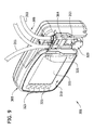
ここで図1−3に図式的に図示される例示的実施形態を参照すると、経腸給送ポンプ(広義には、「流量制御装置」)は、概して、1に示される。ポンプ1は、投与用給送セット5(広義には、「ポンプセット」)が筐体に搭載されることを可能にするように構築される、筐体3を備えてもよい。以下により詳細に説明されるように、ポンプ1は、ポンプ上に装填された給送セット5の状態を検出および識別可能な流動監視システム6(図4)を備えてもよい。筐体3は、給送セット5のカセット9を受容し、給送セットをポンプ上に装填するための陥凹7(図3)を備えてもよい。給送セット5は、栄養液体のバッグ12と患者(図1)との間に流体経路を提供する、概して、11に示される、管類を備えることができる。管類11はまた、洗浄液体のバッグ13との間にも流体経路を提供してもよい。一実施形態では、洗浄流体は、水であってもよい。バッグ12、13は、図1に図式的に示される。カセット9は、カセットが陥凹7内に受容されると、管類とポンプ1を係合させるために、管類11を搭載してもよい。ポンプセットは、本開示の範囲から逸脱することなく、本明細書に示されるもの以外の構造を有してもよいことを理解されたい。例えば、ポンプセット(図示せず)は、本明細書に図示されるようなカセット9を含まなくてもよい。
Here, referring to an exemplary embodiment graphically illustrated in FIG. 1-3, an enteral feeding pump (in a broad sense, a "flow control device") is generally shown in 1. The
本明細書で使用されるように、ポンプ1によって「受容される」給送セット5は、給送セットが患者に流体を送達するためにポンプとの動作の準備ができるように、管類11がポンプ1と係合されることを意味する。用語「筐体」は、本明細書で使用されるように、限定ではないが、多部品構造およびポンプ1の作業構成要素を封入または格納しない構造を含む、多くの形態の支持構造を含んでもよいことを理解されたい。
As used herein, the feed set 5 "accepted" by the
ポンプ1は、ポンプのステータスおよび動作についての情報を表示可能である、筐体3の正面上の21に示されるディスプレイ画面とのユーザインターフェース19を含んでもよい。ポンプ1はさらに、ディスプレイ画面21と併用するためのボタン23および発光ダイオード25を筐体3上に備え、ポンプ1とユーザとの間の情報の提供および取得等、情報の交換を促進することができる。情報をユーザに表示し、ユーザ入力を受信するための種々のユーザインターフェースが、実装されてもよい。ユーザインターフェースの種々の構成のいずれかは、1つ以上のグラフィカルディスプレイサブ構成要素の利用を伴うことができる。実施例として、ディスプレイ画面21は、ユーザが入力情報を提供することができるタッチスクリーンを有する、グラフィカルユーザインターフェースであってもよい。他の実施形態では、ユーザインターフェースは、入力情報を提供する、流量制御装置に関わる動作情報を提供する、または両方のために使用されることができる、テザリングされた構成要素であることができる。
The
図2−4を参照すると、ポンプ1は、筐体3内に位置するポンプモータ27(図4)を含んでもよい。ポンプ回転子29は、回転可能シャフト31上に搭載され、モータ27によって回転されてもよい。一実施形態では、ポンプ回転子29は、内側ディスク39と、外側ディスク41と、好ましくは、ディスクに対してその縦方向軸を中心として回転可能な内側ディスクと外側ディスクとの間に搭載される、複数のローラ43とを含む。
Referring to FIG. 2-4, the
モータ27はまた、弁シャフト45(図3)に接続されてもよい。弁シャフト45は、省略され得る、または別個のモータ(図示せず)が、弁シャフトを動作させるために提供され得ることを理解されたい。ローラ43は、流体を給送セットを通して移動させるために、給送セット5に係合してもよい。図示される実施形態では、ポンプモータ27、回転可能シャフト31、回転子29、および随意の弁シャフト45は、広義には、「圧送デバイス」と見なされ得る。これらの構成要素は、個々に、「圧送デバイス」と見なされ得る。ローラ以外の機構を使用する、蠕動ポンプも、本発明の範囲内であり得ることを理解されたい。しかしながら、他の圧送デバイス(例えば、非回転式デバイス)も、想定される。
The
本明細書で使用されるように、バッグ12、13から回転子29につながる給送セット5の管類11の部分は、「上流」と称される一方、回転子29から離れて患者につながる管類11の部分は、「下流」と称される。故に、回転子29の回転は、管類11を圧縮し、流体(例えば、栄養液体)を給送セット5の上流から下流側における患者方向に駆動させる。例示的給送セット5が、示されるが、他の構成の給送セットおよび他のタイプのポンプセット(図示せず)も、使用されることができる。
As used herein, the portion of
ここで図1、2、および4を参照すると、第1の入口管区分47は、管類11の入口において、給送流体のバッグ12と、弁機構49とに接続される。第2の入口管区分51は、管類11の入口において、洗浄流体のバッグ13と、弁機構とに接続される。弁機構49は、選択的に、バッグ12からの給送流体もしくはバッグ13からの洗浄流体の流動を可能にする、または弁機構を越えた給送もしくは洗浄流体バッグ12、13からのいかなる流体流動連通も防止するように動作可能である。
Here, referring to FIGS. 1, 2, and 4, the first
前述のように、異なる構造のポンプセットが、使用されてもよい、例えば、再認定セットが、ポンプ正確度を検証および/または補正するために使用されてもよい。ポンプ1は、自動的に、設置されたセットの種類を認識し、特定のポンプセットによって要求されるものに準拠するようにその動作を改変するように構成されることができる。なおもさらに、ポンプ1は、管類11がポンプ上に適切に設置されたかどうかを認識し、ポンプセット内の流体の流動状態を判定するように構成されることができる。
As mentioned above, pump sets of different construction may be used, for example, recertification sets may be used to verify and / or correct pump accuracy.
図2−4を参照すると、監視システム6(図4)は、装置上に装填された給送セット5の状態を検出および識別可能である。ポンプ1はさらに、センサ64と通信可能に関連付けられたマイクロプロセッサ62を備えてもよい。マイクロプロセッサ62は、ポンプ1の種々の構成要素の動作を制御および管理してもよい。ソフトウェアサブシステム66は、マイクロプロセッサ62と動作可能に関連付けられ、かつ監視システム6と動作可能に関連付けられ、ポンプ1が給送セット5の状態を検出および識別するための手段を提供してもよい。説明される実施形態では、流動監視システム6、ソフトウェアサブシステム66、ポンプ電子機器68、マイクロプロセッサ62、およびデータベース70(広義には、「メモリ」)は、広義には、「制御回路」と見なされ得ることを理解されたい。これらの構成要素は、個々に、「制御回路」と見なされ得る。さらに、他のタイプの制御回路が、本発明の範囲と併用されてもよい。
With reference to FIGS. 2-4, the monitoring system 6 (FIG. 4) can detect and identify the condition of the feed set 5 loaded on the device.
センサ64は、超音波センサを備えてもよい。センサ64は、ポンプ1の筐体3上に位置し、給送セット5内の流体の存在ならびに流体の1つ以上の特性、例えば、給送セット内の流体の粘度を検出するように位置付けられてもよい。図示される実施形態では、センサ64は、陥凹7内に位置付けられ、給送セット5がポンプ1上に装填されると、管類11をその中にしっかりと受容するように適合される。センサ32が、給送セット5の管類11内の流体の存在を検出するために、管類は、給送セットの下流側を受容するように構成されるセンサトラック68(図3)内に係合および保定されてもよい。いったん管類11が、センサトラック68内に係合され、給送セット5の残りの部分が、ポンプ1と係合されると、監視システム6は、動作可能となり得る。例えば、監視システム6は、センサトラック68内への管類11の確実な係合が、1つ以上の検出器または受信機による、容認可能信号、例えば、超音波信号の受信によって識別されると、動作可能に機能するようになる。
The
好ましくは、センサ64は、超音波信号を管類11の下流部分を通して伝送する、超音波送信機72を備えてもよい。信号は、超音波受信機74に向かって指向され、それによって受信されることができる。超音波信号の受信に応じて、受信機74は、受信機74によって受信される超音波信号の特性に基づいて、管類11内の流体の存在および流体の粘度を検出し、マイクロプロセッサ62に通信されてもよい。
Preferably, the
超音波信号は、管類内の流体の有無を検出し、ポンプ1の動作ステータスの基本インジケーションを与えてもよい。超音波信号は、管類内の流体が、流体が管類内にない場合の信号と比較して、信号の振幅の減少を生成するであろうように、管類11内の流体の存在に応答してもよい。さらに、流体の物理的特性は、送信機からの信号に基づいて評価され、受信機によって受信される際、流体および管類によって変調され得る。例えば、流体の相対的粘度もまた、信号の振幅によって検出されることができる。ある場合には、比較的に低粘度を有する流体は、第1の信号振幅を生じさせ、比較的に高粘度を有する同一流体は、第1の信号振幅より低い第2の信号振幅を生じさせるであろう。受信機74は、次いで、マイクロプロセッサ62と通信してもよい。マイクロプロセッサ62に通信される受信された超音波信号の特性に基づいて、ソフトウェアサブシステム66は、流体が給送セット5内に存在するかどうかと、流体が存在する場合、流体の相対的粘度等の流体の特性とを判定してもよい。例えば、データベース70は、検出されたセンサ信号振幅と関連付けられた特定の粘度を識別するためのルックアップテーブルを含んでもよい。超音波センサ以外の、粘度を含む、1つ以上の流体特性または特徴を測定するための他のタイプのセンサも、使用されることができる。加えて、データベース70は、種々の流体および流体の粘度に対応する複数の所定の信号振幅を記憶してもよい。流動監視システム6は、本開示の範囲から逸脱することなく、給送セット5の他の状態、給送セット内の流体、および給送セットと結合される流体を検出してもよい。
The ultrasonic signal may detect the presence or absence of fluid in the tube and provide a basic indication of the operating status of the
対象に送達される流体の量は、回転子29の回転数によって制御される(図2に見られるように、反時計回り方向に)。図示される実施形態では、1/3ずつの回転が1アリコートの流体を患者に送達するように、回転子29は、3つのローラ43を含む。各ローラ43が、最初に、管類11に係合する際、管類を挟持し、それによって、給送流体バッグ12から流出する流体からの順方向(すなわち、患者に向かって)のある量の流体を閉鎖する。ローラ43は、右に継続し、ローラの前方の流体を患者に向かって押動させる。最後に、ローラ43は、管類11との係合を解除し、それとほぼ同時に、後縁ローラが、管類に係合し、流体の次のアリコートを送達するためにそれを挟持する。したがって、マイクロプロセッサ62が、選択された流体流量を送達するためのコマンドを受信すると、ある数のアリコートを送達し、所望の流量を生成するであろう、所与の時間周期内の回転数を計算する。回転子動作を変更するための他の方法も、一定流量を維持するために使用され得ることを理解されたい。選択された流量は、医師、看護士、もしくは他の医療提供者によって選択された速度であってもよく、またはポンプ1の中に事前にプログラムされたデフォルト給送速度であってもよい。
The amount of fluid delivered to the subject is controlled by the number of revolutions of the rotor 29 (counterclockwise, as seen in FIG. 2). In the illustrated embodiment, the
流体粘度を考慮して、対象に送達される流体の量を制御するために、マイクロプロセッサ62は、モータ27の出力を調節することによって、回転子29の回転速度を調節することができる。したがって、センサ64が、「正常」粘度を表す所定のベースライン信号に基づき得る、比較的に高粘度を有する流体を検出する場合、マイクロプロセッサ62は、モータ27の出力を減少させ、回転子29の回転速度を低下させ、選択された体積をより精密に圧送し、それによって、流体の高粘度を補償することができる。逆に言えば、センサ64が、比較的に低粘度を有する流体を検出する場合、マイクロプロセッサ62は、モータ27の出力を増加させ、回転子29の回転速度を増加させることができる。モータ出力調節がない場合、比較的に高粘度流体は、流体の粘度によって生じる高流動抵抗に起因して、最高正確度の量が分注されないであろう。いくつかの実施形態では、低粘度流体は、約100cP未満の粘度を有し、高粘性流体は、約75cPを上回るまたはそれに等しい粘度を有する。故に、「正常」粘性流体は、約25cP〜約74cPの範囲内の粘度を有し得る。正常範囲内の粘度における流体に関する信号振幅は、マイクロプロセッサ62に、回転子29の回転を調節するように促さないであろう。
In order to control the amount of fluid delivered to the subject in consideration of the fluid viscosity, the
センサ64はまた、給送セットを通して送達されている任意の流体と別個に、給送セット5の状態を検出してもよい。センサ64は、超音波信号を送信機72から給送セット5の管類11を通して指向させるように位置付けられるため、受信機74は、給送セットに特有の信号を受信してもよい。したがって、受信機74において受信される信号は、給送セット5の具体的構造の結果であってもよい。一事例では、給送セット5は、給送セットの機能的構成を表す所定の信号を生成してもよい。例えば、受信機74によって検出された信号は、給送専用、給送および洗浄、または再認定給送セットのうちの1つである、給送セット5を示し得る。他の機能的構成もまた、本開示の範囲内である。データベース70は、種々の機能的に構成に対応する複数の所定の信号を記憶してもよい。
The
図5および6を参照すると、第2のバージョンの給送セット105は、管類111と直接通信するセンサ構成要素175を備えてもよい。図示される実施形態では、センサ構成要素は、管類111上に搭載される。センサ構成要素175は、受信機174において所定の信号を生成し、関連付けられた機能的構成を示すことによって、給送セットの機能的構成を識別してもよい。センサ構成要素175のサイズ、形状、または材料により、受信機174によって受信される信号が決まり得る。したがって、給送専用、洗浄および給送、または再認定構成のうちの1つを備える機能的構成を有する、給送セットは、異なる機能的構成を有する別の給送セットと異なるサイズ、形状、または材料のうちの少なくとも1つを有し得る。例えば、給送専用構成を有するような給送セットを識別するセンサ構成要素は、第1の超音波信号透過特性を有する第1の材料から形成されてもよい。給送および洗浄構成を有するような給送セットを識別するセンサ構成要素は、第1の材料と異なる第2の超音波信号透過特性を有する第2の材料から形成されてもよい。再認定構成を有するような給送セットを識別するセンサ構成要素は、第1および第2の材料と異なる第3の超音波信号透過特性を有する第3の材料から形成されてもよい。
With reference to FIGS. 5 and 6, the second version of the feed set 105 may include a
別の実施形態では、給送専用構成を有するような給送セットを識別するセンサ構成要素は、略長方形形状を有してもよく、給送および洗浄構成を有するような給送セットを識別するセンサ構成要素は、略円筒形形状を有してもよく、再認定構成を有するような給送セットを識別するセンサ構成要素は、略三角形形状を有してもよい。他の形状も、本開示の範囲内で想定される。加えて、大、中、および小センサ構成要素は、給送専用、給送および洗浄、ならびに再認定構成を有する給送セットを区別してもよい。さらに、サイズ、形状および/または材料のある組み合わせは、識別に好適であり得る。 In another embodiment, the sensor component that identifies the feed set, such as having a feed-only configuration, may have a substantially rectangular shape and identifies the feed set, such as having a feed and wash configuration. The sensor component may have a substantially cylindrical shape, and the sensor component that identifies the feed set such as having a recertification configuration may have a substantially triangular shape. Other shapes are also envisioned within the scope of the present disclosure. In addition, the large, medium, and small sensor components may distinguish between feed sets with feed-only, feed and wash, and recertification configurations. In addition, certain combinations of size, shape and / or material may be suitable for identification.
図7および8を参照すると、第3のバージョンのポンプ201は、広超音波信号を管類211の下流部分を通して伝送する超音波送信機272を含む、センサ264を備えてもよい。信号は、複数の超音波受信機274A、274B、274Cに向かって指向され、それらによって受信されることができる。超音波信号の受信に応じて、受信機274A、274B、274Cは、給送セット205の構成を検出してもよい。各受信機274A、274B、274Cは、給送セット205の異なる状態を示す信号を受信してもよい。例えば、受信機274Aにおいて受信される信号は、給送セット205の適切な装填を示してもよく、受信機274Bにおいて受信される信号は、給送セットのタイプを示してもよく、受信機274Cにおいて受信される信号は、給送セット内の流体の粘度を示してもよい。図示される実施形態では、3つの受信機274が、示される。しかしながら、異なる数の受信機274も、本開示の範囲内である。
Referring to FIGS. 7 and 8, the third version of the
図9および10を参照すると、第4のバージョンのポンプ301は、超音波信号を管類311の上流部分を通して第1の方向に伝送し、超音波信号を管類の下流部分を通して第2の方向に伝送する、超音波送信機372を含む、センサ364を備えてもよい。信号は、送信機372の両側の個別の超音波受信機374A、374Bに向かって指向され、それらによって受信されることができる。給送セット305は、管類311の上流部分が、送信機372と受信機374Aとの間に配置され、管類の下流部分が、送信機と受信機374Bとの間に配置されるように、ポンプ301上に装填されることができる。超音波信号の受信に応じて、受信機374A、374Bは、超音波信号の特性(例えば、信号振幅)に基づいて、管類311内の流体の存在および/または流体の粘度を検出してもよい。受信機374A、374Bはまた、給送セット305の他の状態を検出してもよい。
Referring to FIGS. 9 and 10, the fourth version of the
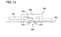
図11を参照すると、第5のバージョンのポンプ401は、給送セットがポンプによって受容されると、給送セット405の真下に配置される超音波送信機472および超音波受信機474を含む、センサ464を備えてもよい。超音波送信機472は、超音波信号を給送セットの管類411を通して給送セット405に向かって伝送してもよい。給送セット405は、超音波信号を管類411を通して超音波受信機474に向かって反射させる反射内側表面475を有する、カセット409を含んでもよい。反射表面475はまた、送信機472から放出される超音波信号を受信機474に向かって指向させるように角度付けられてもよい。本構成は、管類411が送信機472と受信機474との間に載置される必要がないため、より可変のポンプ設計を可能にする。管類411をセンサ464にわたって載置することによって、給送セット405の装填プロセスは、簡略化され、したがって、エラーを伴わずに、装填プロセスをより容易に再現可能にすることができる。さらに、ポンプ401の全体的構成は、センサ464の組み込みよって過度に制約されない。
Referring to FIG. 11, the fifth version of the
本発明の実施形態は、1つ以上のコンピュータもしくは他のデバイスによって実行される、プログラムモジュール等のコンピュータ実行可能命令を用いて、実装されてもよい。コンピュータ実行可能命令は、限定ではないが、特定のタスクを行う、または特定の抽象データタイプを実装する、ルーチン、プログラム、オブジェクト、構成要素、およびデータ構造を含む、1つ以上のコンピュータ実行可能構成要素またはモジュールの中に編成されてもよい。本発明の側面は、任意の数および編成のそのような構成要素またはモジュールを用いて、実装されてもよい。例えば、本発明の側面は、図に例証され、かつ本明細書に説明される具体的なコンピュータ実行可能命令あるいは具体的な構成要素またはモジュールに限定されない。他の本発明の実施形態は、本明細書に例証かつ説明されるよりも、多いまたは少ない機能性を有する異なるコンピュータ実行可能命令または構成要素を含んでもよい。 Embodiments of the present invention may be implemented using computer-executable instructions such as program modules that are executed by one or more computers or other devices. A computer-executable instruction is one or more computer-executable configurations that include, but are not limited to, routines, programs, objects, components, and data structures that perform a particular task or implement a particular abstract data type. It may be organized within an element or module. Aspects of the invention may be implemented using any number and organization of such components or modules. For example, aspects of the invention are not limited to the specific computer executable instructions or specific components or modules illustrated and described herein. Other embodiments of the invention may include different computer executable instructions or components that have more or less functionality than is illustrated and illustrated herein.
さらに、本明細書に図示および説明される本発明の実施形態における動作の実行または実施の順序は、別様に規定されない限り、不可欠ではない。すなわち、動作は、別様に規定されない限り、任意の順序で行われてもよく、本発明の実施形態は、付加的または本明細書に開示されるものより少ない動作を含んでもよい。例えば、別の動作の前に、それと同時に、またはその後に、特定の動作を実行もしくは実施することも、本発明の側面の範囲内であることが検討される。 Moreover, the order of execution or execution of the operations in the embodiments of the invention illustrated and described herein is not essential unless otherwise specified. That is, the actions may be performed in any order, unless otherwise specified, and embodiments of the present invention may include additional or less actions than those disclosed herein. For example, performing or performing a particular action before, at the same time, or after another action is also considered within the scope of aspects of the invention.
動作時、マイクロプロセッサ62は、本発明の側面を実装するために、図に図示されるもの等のコンピュータ実行可能命令を実行する。本発明の側面はまた、分散型コンピューティング環境において実践されてもよく、タスクは、通信ネットワークを通してリンクされた遠隔処理デバイスによって行われる。分散型コンピューティング環境では、プログラムモジュールは、メモリ記憶デバイスを含む、ローカルおよび遠隔コンピュータ記憶媒体の両方に位置してもよい。
In operation, the
詳細に本発明を説明したが、修正および変形例が、添付の特許請求の範囲に定義される本発明の範囲から逸脱せずに、可能であることは、明白であろう。 Having described the invention in detail, it will be clear that modifications and modifications are possible without departing from the scope of the invention as defined in the appended claims.
本発明の要素またはその好ましい実施形態を導入するとき、冠詞「a」、「an」、「the」、および「said」は、要素の1つ以上のものであることを意味することが意図される。用語「comprising(備える)」、「including(含む)」、および「having(有する)」は、列挙された要素以外の付加的要素が存在し得ることを含み、かつ意味することが意図される。 When introducing the elements of the invention or preferred embodiments thereof, the articles "a", "an", "the", and "said" are intended to mean one or more of the elements. NS. The terms "comprising", "inclusion", and "having" are intended to include and mean that additional elements other than those listed may be present.
上記を考慮して、本発明のいくつかの目的が達成され、かつ他の利点となる結果が獲得されることが分かるであろう。 In view of the above, it will be found that some objects of the present invention are achieved and other beneficial results are obtained.
種々の変更が、本発明の範囲から逸脱せずに、上記の構成および方法に行なわれ得るため、上記の説明に含有され、かつ付随の図面に示される全ての内容は、例証として解釈され、限定的な意味でないことが意図される。 All content contained in the above description and shown in the accompanying drawings is to be construed as an example, as various modifications can be made to the above configurations and methods without departing from the scope of the present invention. It is intended not to have a limiting meaning.
Claims (13)
対象への流体の送達のために、前記給送セットに作用して前記給送セット内に流体流動を生成するように構成された圧送デバイスを含む流量制御装置と、
前記圧送デバイスに対して配置され、前記給送セットを感知する超音波センサであって、超音波信号を放出するように構成された超音波エミッタと、前記超音波信号を検出するように構成された超音波検出器とを含む超音波センサと、
前記超音波信号の経路内に配置され、前記給送セットの状態を示す、前記超音波検出器によって検出可能な信号を生成する前記給送セットの一部と、
前記超音波センサと通信し、前記超音波センサから受信したセンサ信号に基づいて前記給送セットのタイプを識別するように構成された制御回路であって、前記制御回路は、前記給送セットの複数の識別を含有するメモリを含み、前記制御回路は、前記センサ信号と前記複数の記憶された識別のうちの1つを合致させ、前記センサ信号に合致する前記記憶された識別と関連付けられた1つ以上の特性に基づいて前記流量制御装置の動作を制御するように構成される制御回路と
を含む、流量制御システム。 A flow control system for delivering fluid to a subject through a feed set,
A flow control device comprising a pumping device configured to act on the feed set to generate fluid flow within the feed set for delivery of fluid to a subject.
An ultrasonic sensor arranged with respect to the pumping device and sensing the feeding set, the ultrasonic emitter configured to emit an ultrasonic signal and configured to detect the ultrasonic signal. Ultrasonic sensors, including ultrasonic detectors ,
Disposed in the path of the previous SL ultrasound signals, indicating the state of the feed set, a part of the feeding set to generate a detectable signal by the ultrasonic detector,
A control circuit configured to communicate with an ultrasonic sensor and identify the type of feed set based on a sensor signal received from the ultrasonic sensor, wherein the control circuit is of the feed set. A memory containing a plurality of identifications is included, and the control circuit matches the sensor signal with one of the plurality of stored identifications and is associated with the stored identification matching the sensor signal. A control circuit configured to control the operation of the flow control device based on one or more characteristics.
Flow control system , including.
前記超音波センサは、単一の超音波エミッタと、複数の超音波検出器とを含む、請求項1に記載の流量制御システム。The flow rate control system according to claim 1, wherein the ultrasonic sensor includes a single ultrasonic emitter and a plurality of ultrasonic detectors.
前記超音波エミッタは、前記給送セットが前記筐体によって受容されたときに前記給送セットの第1の部分に向かって第1の方向に第1の信号を放出しかつ前記給送セットの第2の部分に向かって前記第1の方向と異なる第2の方向に第2の信号を放出するように前記圧送デバイスに対して構築及び配置され、前記第1及び第2の信号は、前記第1及び第2の部分における前記給送セットの状態を示すために使用される、請求項1に記載の流量制御システム。The ultrasonic emitter emits a first signal in a first direction towards a first portion of the feed set when the feed set is received by the housing and of the feed set. The first and second signals are constructed and arranged with respect to the pumping device so as to emit a second signal in a second direction different from the first direction toward the second portion. The flow control system according to claim 1, which is used to indicate the state of the feed set in the first and second parts.
Applications Claiming Priority (3)
| Application Number | Priority Date | Filing Date | Title |
|---|---|---|---|
| US201462028983P | 2014-07-25 | 2014-07-25 | |
| US62/028,983 | 2014-07-25 | ||
| JP2017503824A JP6625116B2 (en) | 2014-07-25 | 2015-07-22 | Flow control device |
Related Parent Applications (1)
| Application Number | Title | Priority Date | Filing Date |
|---|---|---|---|
| JP2017503824A Division JP6625116B2 (en) | 2014-07-25 | 2015-07-22 | Flow control device |
Publications (3)
| Publication Number | Publication Date |
|---|---|
| JP2020060188A JP2020060188A (en) | 2020-04-16 |
| JP2020060188A5 JP2020060188A5 (en) | 2021-04-22 |
| JP6905570B2 true JP6905570B2 (en) | 2021-07-21 |
Family
ID=53761614
Family Applications (2)
| Application Number | Title | Priority Date | Filing Date |
|---|---|---|---|
| JP2017503824A Active JP6625116B2 (en) | 2014-07-25 | 2015-07-22 | Flow control device |
| JP2019212775A Active JP6905570B2 (en) | 2014-07-25 | 2019-11-26 | Flow control system |
Family Applications Before (1)
| Application Number | Title | Priority Date | Filing Date |
|---|---|---|---|
| JP2017503824A Active JP6625116B2 (en) | 2014-07-25 | 2015-07-22 | Flow control device |
Country Status (7)
| Country | Link |
|---|---|
| US (1) | US9820916B2 (en) |
| EP (3) | EP4321144A3 (en) |
| JP (2) | JP6625116B2 (en) |
| AU (1) | AU2015292641B2 (en) |
| CA (1) | CA2955614C (en) |
| ES (1) | ES2963924T3 (en) |
| WO (1) | WO2016014651A1 (en) |
Families Citing this family (12)
| Publication number | Priority date | Publication date | Assignee | Title |
|---|---|---|---|---|
| US10227971B2 (en) * | 2014-08-12 | 2019-03-12 | Kpr U.S., Llc | Downstream flow detection system for flow control apparatus |
| WO2020006326A1 (en) | 2018-06-29 | 2020-01-02 | Generica Medical International, Inc. | Enteral feeding systems and methods |
| US11344480B2 (en) | 2018-07-26 | 2022-05-31 | Medline Industries, Lp | Enteral fluid delivery system |
| BR112021010024A2 (en) | 2018-11-26 | 2021-08-17 | Kpr U.S., Llc | cassette for a flow control device |
| US10765798B2 (en) | 2019-01-24 | 2020-09-08 | Medline Industries, Inc. | Feeding syringe holder |
| USD920504S1 (en) | 2019-07-01 | 2021-05-25 | Medline Industries, Inc. | Valve |
| USD906516S1 (en) | 2019-07-01 | 2020-12-29 | Medline Industries, Inc. | Valve clip |
| US11110036B2 (en) | 2019-07-01 | 2021-09-07 | Medline Industries, Inc. | Feeding set and enteral feeding pump assembly |
| WO2021064497A1 (en) | 2019-09-30 | 2021-04-08 | Johnson & Johnson Surgical Vision, Inc. | Systems and methods for identifying cassette type in a surgical system |
| CA3175692A1 (en) * | 2020-05-22 | 2021-11-25 | Wayne T. Biermann | Detection system for flow control apparatus |
| US20220379023A1 (en) * | 2021-05-24 | 2022-12-01 | Kpr U.S., Llc | Enteral feeding liquid deliver |
| CN115539362B (en) * | 2022-09-13 | 2025-05-02 | 杭州康基医疗器械有限公司 | Medical Peristaltic Pump |
Family Cites Families (67)
| Publication number | Priority date | Publication date | Assignee | Title |
|---|---|---|---|---|
| US3553636A (en) * | 1969-01-27 | 1971-01-05 | Bindicator Co | Noncontact ultrasonic interface viscosity and percent solid detecting device |
| NL165295C (en) | 1970-04-08 | 1981-03-16 | Shell Int Research | METHOD FOR INSPECTING A PIPELINE. |
| US4037598A (en) | 1974-08-12 | 1977-07-26 | Ivac Corporation | Method and apparatus for fluid flow control |
| US4441358A (en) | 1981-12-07 | 1984-04-10 | Osborne Robert L | Automated ultrasonic solution viscometer |
| US4820265A (en) | 1986-12-16 | 1989-04-11 | Minnesota Mining And Manufacturing Company | Tubing set |
| US4781525A (en) | 1987-07-17 | 1988-11-01 | Minnesota Mining And Manufacturing Company | Flow measurement system |
| US4872813A (en) | 1987-12-01 | 1989-10-10 | Pacesetter Infusion, Ltd. | Disposable cassette for a medication infusion system |
| US4878896A (en) | 1987-12-01 | 1989-11-07 | Pacesetter Infusion, Ltd. | Cassette optical identification apparatus for a medication infusion system |
| US4976590A (en) | 1988-06-08 | 1990-12-11 | Baldwin Brian E | Fluid conduit-responsively adjustable pump arrangement and pump/conduit arrangement and method, and fluid conduits therefor |
| US6022195A (en) | 1988-09-13 | 2000-02-08 | Helix Technology Corporation | Electronically controlled vacuum pump with control module |
| US4967797A (en) | 1989-08-16 | 1990-11-06 | Manska Wayne E | Tap valve |
| US5135026A (en) | 1989-08-16 | 1992-08-04 | Manska Wayne E | Medical valve having fluid flow indicia |
| US5176631A (en) | 1989-09-05 | 1993-01-05 | Pacesetter Infusion, Ltd. | Ultrasonic air-in-line detector for detecting entrained air in a medication infusion system |
| US5145314A (en) | 1991-04-18 | 1992-09-08 | Sundstrand Corporation | Low drag pitot pump and method of operating same |
| EP0692265B1 (en) | 1991-08-21 | 2000-05-24 | Smith & Nephew, Inc. | Fluid management system |
| JPH06307343A (en) * | 1993-04-26 | 1994-11-01 | Sharp Corp | Infusion pump device |
| US5741961A (en) * | 1993-08-18 | 1998-04-21 | Sandia Corporation | Quartz resonator fluid density and viscosity monitor |
| JP3320179B2 (en) | 1993-12-17 | 2002-09-03 | シャープ株式会社 | Infusion pump |
| US5460490A (en) | 1994-05-19 | 1995-10-24 | Linvatec Corporation | Multi-purpose irrigation/aspiration pump system |
| US5514102A (en) * | 1995-05-05 | 1996-05-07 | Zevex Incorporated | Pressure monitoring enteral feeding system and method |
| US5926096A (en) | 1996-03-11 | 1999-07-20 | The Foxboro Company | Method and apparatus for correcting for performance degrading factors in a coriolis-type mass flowmeter |
| US5843035A (en) * | 1996-04-10 | 1998-12-01 | Baxter International Inc. | Air detector for intravenous infusion system |
| US5810770A (en) | 1996-12-13 | 1998-09-22 | Stryker Corporation | Fluid management pump system for surgical procedures |
| US6227040B1 (en) * | 1998-02-03 | 2001-05-08 | Caldon, Inc. | Method and apparatus for determining the viscosity of a fluid in a container |
| US6098466A (en) | 1998-06-09 | 2000-08-08 | Transonic Systems, Inc. | Ultrasonic flow sensor incorporating full flow illumination |
| US6711958B2 (en) | 2000-05-12 | 2004-03-30 | Endress + Hauser Flowtec Ag | Coriolis mass flow rate/density/viscoy sensor with two bent measuring tubes |
| US6659976B2 (en) | 2001-04-16 | 2003-12-09 | Zevek, Inc. | Feeding set adaptor |
| JPWO2003006955A1 (en) * | 2001-07-12 | 2004-11-04 | 日本ゼオン株式会社 | Method and apparatus for measuring Mooney viscosity, and method and apparatus for producing polymer |
| US7207939B2 (en) * | 2002-10-03 | 2007-04-24 | Coulter International Corp. | Apparatus and method for analyzing a liquid in a capillary tube of a hematology instrument |
| US6901812B2 (en) * | 2002-12-30 | 2005-06-07 | Pti Technologies, Inc. | Single-body dual-chip Orthogonal sensing transit-time flow device |
| US20040213677A1 (en) | 2003-04-24 | 2004-10-28 | Matzner Mark D. | Monitoring system for reciprocating pumps |
| BR0301969A (en) | 2003-05-22 | 2005-03-15 | Brasil Compressores Sa | Sensor assembly, fluid pump and cooler |
| DE602005019219D1 (en) | 2004-03-24 | 2010-03-25 | Terumo Corp | Centrifugal blood pump with hydrodynamic bearing |
| PL1732627T3 (en) | 2004-03-31 | 2010-09-30 | Lilly Co Eli | Injection apparatus having a needle cassette for delivering a pharmaceutical liquid |
| JP4521547B2 (en) | 2004-04-15 | 2010-08-11 | 株式会社サンメディカル技術研究所 | Blood pump flow estimation device |
| US7753880B2 (en) | 2004-09-28 | 2010-07-13 | Stryker Corporation | Method of operating a surgical irrigation pump capable of performing a priming operation |
| MX2007009289A (en) * | 2005-02-01 | 2008-01-28 | Baxter Int | Infusion delivery system. |
| US8006570B2 (en) | 2006-03-29 | 2011-08-30 | Alcon, Inc. | Non-invasive flow measurement |
| US8343100B2 (en) | 2006-03-29 | 2013-01-01 | Novartis Ag | Surgical system having a non-invasive flow sensor |
| US8348879B2 (en) | 2006-08-28 | 2013-01-08 | Novartis Ag | Surgical system having a cassette with an acoustic air reflector |
| WO2008051939A2 (en) | 2006-10-24 | 2008-05-02 | Medapps, Inc. | Systems and methods for medical data transmission |
| US7704227B2 (en) | 2006-11-29 | 2010-04-27 | Medtronic Minimed, Inc. | Methods and apparatuses for detecting medical device acceleration, temperature, and humidity conditions |
| US7789850B2 (en) | 2007-01-22 | 2010-09-07 | Baxter International Inc. | Weight controlled dialysis system with accelerometer |
| US7748256B2 (en) | 2007-07-03 | 2010-07-06 | Caterpillar Inc. | Nondestructive testing of torsional vibration dampers |
| US7879026B2 (en) | 2007-09-07 | 2011-02-01 | Asante Solutions, Inc. | Controlled adjustment of medicine dispensation from an infusion pump device |
| US8154417B2 (en) | 2007-10-05 | 2012-04-10 | Itt Manufacturing Enterprises, Inc. | Compact self-contained condition monitoring device |
| EP2052683A1 (en) | 2007-10-23 | 2009-04-29 | Sensile Pat AG | Liquid flow sensing system |
| US20090177142A1 (en) | 2008-01-09 | 2009-07-09 | Smiths Medical Md, Inc | Insulin pump with add-on modules |
| US7762989B2 (en) | 2008-02-08 | 2010-07-27 | Baxter International Inc. | Method and apparatus for preventing the use of unauthorized disposable sets in infusion pumps |
| DE102008019992B4 (en) * | 2008-04-21 | 2010-07-01 | Mib Gmbh Messtechnik Und Industrieberatung | Ultrasonic measuring arrangement |
| US8795225B2 (en) | 2008-09-29 | 2014-08-05 | Covidien Lp | Fluid detection in an enteral feeding set |
| US8676387B2 (en) | 2008-10-13 | 2014-03-18 | General Electric Company | Methods and systems for determining operating states of pumps |
| WO2010053706A1 (en) | 2008-11-10 | 2010-05-14 | Delphi Technologies, Inc. | Alarm identification system for infusion set when installed in pump assembly |
| US20100152544A1 (en) | 2008-11-19 | 2010-06-17 | Spectrum Medical Limited | Cardiac monitoring system and method |
| DE102009009592A1 (en) | 2009-02-19 | 2010-08-26 | Clyde Bergemann Gmbh Maschinen- Und Apparatebau | Measuring device for a heat exchanger |
| US8790303B2 (en) | 2009-03-09 | 2014-07-29 | Thermedx, Llc | Fluid management system heater assembly and cartridge |
| CN101706403B (en) * | 2009-09-10 | 2011-11-23 | 浙江大学 | Method for detecting viscosity of flowing system |
| US8386042B2 (en) | 2009-11-03 | 2013-02-26 | Medtronic Minimed, Inc. | Omnidirectional accelerometer device and medical device incorporating same |
| US8594969B2 (en) | 2010-04-01 | 2013-11-26 | Thomas Martin Lill | Remote appliance or machine monitoring method and system |
| US8926291B2 (en) | 2010-07-19 | 2015-01-06 | Michael Orndorff | Speed control for diaphragm pump |
| US8857269B2 (en) | 2010-08-05 | 2014-10-14 | Hospira, Inc. | Method of varying the flow rate of fluid from a medical pump and hybrid sensor system performing the same |
| JP6266348B2 (en) | 2011-02-16 | 2018-01-24 | セクアナ メディカル エージー | Body fluid management system |
| US9033923B2 (en) | 2011-07-25 | 2015-05-19 | Nestec S.A. | Infrared reflective air-in-line sensor system |
| US8459968B2 (en) | 2011-09-19 | 2013-06-11 | Curlin Medical Inc. | Peristaltic pump cassette and method of installing same |
| JP5955589B2 (en) * | 2012-02-29 | 2016-07-20 | テルモ株式会社 | Medical device with medical device inspection mode |
| US8817258B2 (en) * | 2012-05-21 | 2014-08-26 | Common Sensing Inc. | Dose measurement system and method |
| EP2920465B1 (en) * | 2012-11-14 | 2019-05-01 | Kpr U.S., Llc | Peristaltic pump cassette |
-
2015
- 2015-07-22 JP JP2017503824A patent/JP6625116B2/en active Active
- 2015-07-22 EP EP23195433.0A patent/EP4321144A3/en active Pending
- 2015-07-22 EP EP15744457.1A patent/EP3171912B1/en active Active
- 2015-07-22 AU AU2015292641A patent/AU2015292641B2/en active Active
- 2015-07-22 ES ES19210210T patent/ES2963924T3/en active Active
- 2015-07-22 WO PCT/US2015/041510 patent/WO2016014651A1/en not_active Ceased
- 2015-07-22 EP EP19210210.1A patent/EP3689393B1/en active Active
- 2015-07-22 CA CA2955614A patent/CA2955614C/en active Active
- 2015-07-22 US US14/806,159 patent/US9820916B2/en active Active
-
2019
- 2019-11-26 JP JP2019212775A patent/JP6905570B2/en active Active
Also Published As
| Publication number | Publication date |
|---|---|
| EP4321144A3 (en) | 2024-04-10 |
| EP3689393C0 (en) | 2023-09-06 |
| AU2015292641A1 (en) | 2017-02-02 |
| JP2017522966A (en) | 2017-08-17 |
| CA2955614A1 (en) | 2016-01-28 |
| AU2015292641B2 (en) | 2020-08-20 |
| EP3689393A1 (en) | 2020-08-05 |
| JP6625116B2 (en) | 2019-12-25 |
| EP3171912B1 (en) | 2019-11-20 |
| WO2016014651A1 (en) | 2016-01-28 |
| CA2955614C (en) | 2020-08-25 |
| EP3171912A1 (en) | 2017-05-31 |
| JP2020060188A (en) | 2020-04-16 |
| EP3689393B1 (en) | 2023-09-06 |
| EP4321144A2 (en) | 2024-02-14 |
| US20160022545A1 (en) | 2016-01-28 |
| ES2963924T3 (en) | 2024-04-03 |
| US9820916B2 (en) | 2017-11-21 |
Similar Documents
| Publication | Publication Date | Title |
|---|---|---|
| JP6905570B2 (en) | Flow control system | |
| JP2017522966A5 (en) | ||
| CN106687154B (en) | Systems and methods for administering reduced pressure therapy | |
| US10227971B2 (en) | Downstream flow detection system for flow control apparatus | |
| AU2019201533A1 (en) | Feeding set and enteral feeding pump | |
| CN105848694A (en) | Fluid control system and disposable assembly | |
| EP3866881B1 (en) | Pump flow adjusting system | |
| JP2017530818A (en) | Blockage detection for flow control devices | |
| EP3289499B1 (en) | Detection of malfunction of a flow control apparatus | |
| JP5306409B2 (en) | Improved safety interlock | |
| CN117642195A (en) | Enteral feeding liquid delivery | |
| CN115737982A (en) | Ultrasonic infusion monitor | |
| US12121699B1 (en) | Systems and methods for monitoring operations of an infusion delivery device using a pressure sensor | |
| CN115551571B (en) | Detection system for flow control equipment | |
| JP2025526649A (en) | Occlusion detection system and method for flow control devices | |
| HK1226978B (en) | Fluid control system and disposable assembly |
Legal Events
| Date | Code | Title | Description |
|---|---|---|---|
| A521 | Request for written amendment filed |
Free format text: JAPANESE INTERMEDIATE CODE: A523 Effective date: 20191226 |
|
| A621 | Written request for application examination |
Free format text: JAPANESE INTERMEDIATE CODE: A621 Effective date: 20191226 |
|
| A131 | Notification of reasons for refusal |
Free format text: JAPANESE INTERMEDIATE CODE: A131 Effective date: 20201221 |
|
| A524 | Written submission of copy of amendment under article 19 pct |
Free format text: JAPANESE INTERMEDIATE CODE: A524 Effective date: 20210304 |
|
| TRDD | Decision of grant or rejection written | ||
| A01 | Written decision to grant a patent or to grant a registration (utility model) |
Free format text: JAPANESE INTERMEDIATE CODE: A01 Effective date: 20210608 |
|
| A61 | First payment of annual fees (during grant procedure) |
Free format text: JAPANESE INTERMEDIATE CODE: A61 Effective date: 20210625 |
|
| R150 | Certificate of patent or registration of utility model |
Ref document number: 6905570 Country of ref document: JP Free format text: JAPANESE INTERMEDIATE CODE: R150 |
|
| R250 | Receipt of annual fees |
Free format text: JAPANESE INTERMEDIATE CODE: R250 |
|
| R250 | Receipt of annual fees |
Free format text: JAPANESE INTERMEDIATE CODE: R250 |