JP6902201B2 - Vehicle power supply - Google Patents
Vehicle power supply Download PDFInfo
- Publication number
- JP6902201B2 JP6902201B2 JP2016196273A JP2016196273A JP6902201B2 JP 6902201 B2 JP6902201 B2 JP 6902201B2 JP 2016196273 A JP2016196273 A JP 2016196273A JP 2016196273 A JP2016196273 A JP 2016196273A JP 6902201 B2 JP6902201 B2 JP 6902201B2
- Authority
- JP
- Japan
- Prior art keywords
- power storage
- power supply
- switch
- storage device
- battery
- Prior art date
- Legal status (The legal status is an assumption and is not a legal conclusion. Google has not performed a legal analysis and makes no representation as to the accuracy of the status listed.)
- Active
Links
Images


Classifications
-
- H—ELECTRICITY
- H02—GENERATION; CONVERSION OR DISTRIBUTION OF ELECTRIC POWER
- H02J—CIRCUIT ARRANGEMENTS OR SYSTEMS FOR SUPPLYING OR DISTRIBUTING ELECTRIC POWER; SYSTEMS FOR STORING ELECTRIC ENERGY
- H02J7/00—Circuit arrangements for charging or depolarising batteries or for supplying loads from batteries
- H02J7/0013—Circuit arrangements for charging or depolarising batteries or for supplying loads from batteries acting upon several batteries simultaneously or sequentially
-
- H—ELECTRICITY
- H01—ELECTRIC ELEMENTS
- H01M—PROCESSES OR MEANS, e.g. BATTERIES, FOR THE DIRECT CONVERSION OF CHEMICAL ENERGY INTO ELECTRICAL ENERGY
- H01M10/00—Secondary cells; Manufacture thereof
- H01M10/42—Methods or arrangements for servicing or maintenance of secondary cells or secondary half-cells
- H01M10/425—Structural combination with electronic components, e.g. electronic circuits integrated to the outside of the casing
-
- B—PERFORMING OPERATIONS; TRANSPORTING
- B60—VEHICLES IN GENERAL
- B60L—PROPULSION OF ELECTRICALLY-PROPELLED VEHICLES; SUPPLYING ELECTRIC POWER FOR AUXILIARY EQUIPMENT OF ELECTRICALLY-PROPELLED VEHICLES; ELECTRODYNAMIC BRAKE SYSTEMS FOR VEHICLES IN GENERAL; MAGNETIC SUSPENSION OR LEVITATION FOR VEHICLES; MONITORING OPERATING VARIABLES OF ELECTRICALLY-PROPELLED VEHICLES; ELECTRIC SAFETY DEVICES FOR ELECTRICALLY-PROPELLED VEHICLES
- B60L50/00—Electric propulsion with power supplied within the vehicle
- B60L50/50—Electric propulsion with power supplied within the vehicle using propulsion power supplied by batteries or fuel cells
- B60L50/60—Electric propulsion with power supplied within the vehicle using propulsion power supplied by batteries or fuel cells using power supplied by batteries
- B60L50/64—Constructional details of batteries specially adapted for electric vehicles
-
- B—PERFORMING OPERATIONS; TRANSPORTING
- B60—VEHICLES IN GENERAL
- B60L—PROPULSION OF ELECTRICALLY-PROPELLED VEHICLES; SUPPLYING ELECTRIC POWER FOR AUXILIARY EQUIPMENT OF ELECTRICALLY-PROPELLED VEHICLES; ELECTRODYNAMIC BRAKE SYSTEMS FOR VEHICLES IN GENERAL; MAGNETIC SUSPENSION OR LEVITATION FOR VEHICLES; MONITORING OPERATING VARIABLES OF ELECTRICALLY-PROPELLED VEHICLES; ELECTRIC SAFETY DEVICES FOR ELECTRICALLY-PROPELLED VEHICLES
- B60L58/00—Methods or circuit arrangements for monitoring or controlling batteries or fuel cells, specially adapted for electric vehicles
- B60L58/10—Methods or circuit arrangements for monitoring or controlling batteries or fuel cells, specially adapted for electric vehicles for monitoring or controlling batteries
- B60L58/12—Methods or circuit arrangements for monitoring or controlling batteries or fuel cells, specially adapted for electric vehicles for monitoring or controlling batteries responding to state of charge [SoC]
-
- B—PERFORMING OPERATIONS; TRANSPORTING
- B60—VEHICLES IN GENERAL
- B60L—PROPULSION OF ELECTRICALLY-PROPELLED VEHICLES; SUPPLYING ELECTRIC POWER FOR AUXILIARY EQUIPMENT OF ELECTRICALLY-PROPELLED VEHICLES; ELECTRODYNAMIC BRAKE SYSTEMS FOR VEHICLES IN GENERAL; MAGNETIC SUSPENSION OR LEVITATION FOR VEHICLES; MONITORING OPERATING VARIABLES OF ELECTRICALLY-PROPELLED VEHICLES; ELECTRIC SAFETY DEVICES FOR ELECTRICALLY-PROPELLED VEHICLES
- B60L58/00—Methods or circuit arrangements for monitoring or controlling batteries or fuel cells, specially adapted for electric vehicles
- B60L58/10—Methods or circuit arrangements for monitoring or controlling batteries or fuel cells, specially adapted for electric vehicles for monitoring or controlling batteries
- B60L58/18—Methods or circuit arrangements for monitoring or controlling batteries or fuel cells, specially adapted for electric vehicles for monitoring or controlling batteries of two or more battery modules
- B60L58/21—Methods or circuit arrangements for monitoring or controlling batteries or fuel cells, specially adapted for electric vehicles for monitoring or controlling batteries of two or more battery modules having the same nominal voltage
-
- H—ELECTRICITY
- H01—ELECTRIC ELEMENTS
- H01M—PROCESSES OR MEANS, e.g. BATTERIES, FOR THE DIRECT CONVERSION OF CHEMICAL ENERGY INTO ELECTRICAL ENERGY
- H01M10/00—Secondary cells; Manufacture thereof
- H01M10/05—Accumulators with non-aqueous electrolyte
- H01M10/052—Li-accumulators
- H01M10/0525—Rocking-chair batteries, i.e. batteries with lithium insertion or intercalation in both electrodes; Lithium-ion batteries
-
- H—ELECTRICITY
- H01—ELECTRIC ELEMENTS
- H01M—PROCESSES OR MEANS, e.g. BATTERIES, FOR THE DIRECT CONVERSION OF CHEMICAL ENERGY INTO ELECTRICAL ENERGY
- H01M10/00—Secondary cells; Manufacture thereof
- H01M10/42—Methods or arrangements for servicing or maintenance of secondary cells or secondary half-cells
- H01M10/4207—Methods or arrangements for servicing or maintenance of secondary cells or secondary half-cells for several batteries or cells simultaneously or sequentially
-
- H—ELECTRICITY
- H01—ELECTRIC ELEMENTS
- H01M—PROCESSES OR MEANS, e.g. BATTERIES, FOR THE DIRECT CONVERSION OF CHEMICAL ENERGY INTO ELECTRICAL ENERGY
- H01M10/00—Secondary cells; Manufacture thereof
- H01M10/42—Methods or arrangements for servicing or maintenance of secondary cells or secondary half-cells
- H01M10/48—Accumulators combined with arrangements for measuring, testing or indicating the condition of cells, e.g. the level or density of the electrolyte
- H01M10/482—Accumulators combined with arrangements for measuring, testing or indicating the condition of cells, e.g. the level or density of the electrolyte for several batteries or cells simultaneously or sequentially
-
- H—ELECTRICITY
- H01—ELECTRIC ELEMENTS
- H01M—PROCESSES OR MEANS, e.g. BATTERIES, FOR THE DIRECT CONVERSION OF CHEMICAL ENERGY INTO ELECTRICAL ENERGY
- H01M4/00—Electrodes
- H01M4/02—Electrodes composed of, or comprising, active material
- H01M4/36—Selection of substances as active materials, active masses, active liquids
- H01M4/58—Selection of substances as active materials, active masses, active liquids of inorganic compounds other than oxides or hydroxides, e.g. sulfides, selenides, tellurides, halogenides or LiCoFy; of polyanionic structures, e.g. phosphates, silicates or borates
- H01M4/5825—Oxygenated metallic salts or polyanionic structures, e.g. borates, phosphates, silicates, olivines
-
- H—ELECTRICITY
- H01—ELECTRIC ELEMENTS
- H01M—PROCESSES OR MEANS, e.g. BATTERIES, FOR THE DIRECT CONVERSION OF CHEMICAL ENERGY INTO ELECTRICAL ENERGY
- H01M4/00—Electrodes
- H01M4/02—Electrodes composed of, or comprising, active material
- H01M4/36—Selection of substances as active materials, active masses, active liquids
- H01M4/58—Selection of substances as active materials, active masses, active liquids of inorganic compounds other than oxides or hydroxides, e.g. sulfides, selenides, tellurides, halogenides or LiCoFy; of polyanionic structures, e.g. phosphates, silicates or borates
- H01M4/583—Carbonaceous material, e.g. graphite-intercalation compounds or CFx
- H01M4/587—Carbonaceous material, e.g. graphite-intercalation compounds or CFx for inserting or intercalating light metals
-
- H—ELECTRICITY
- H01—ELECTRIC ELEMENTS
- H01M—PROCESSES OR MEANS, e.g. BATTERIES, FOR THE DIRECT CONVERSION OF CHEMICAL ENERGY INTO ELECTRICAL ENERGY
- H01M50/00—Constructional details or processes of manufacture of the non-active parts of electrochemical cells other than fuel cells, e.g. hybrid cells
- H01M50/20—Mountings; Secondary casings or frames; Racks, modules or packs; Suspension devices; Shock absorbers; Transport or carrying devices; Holders
- H01M50/249—Mountings; Secondary casings or frames; Racks, modules or packs; Suspension devices; Shock absorbers; Transport or carrying devices; Holders specially adapted for aircraft or vehicles, e.g. cars or trains
-
- H—ELECTRICITY
- H02—GENERATION; CONVERSION OR DISTRIBUTION OF ELECTRIC POWER
- H02J—CIRCUIT ARRANGEMENTS OR SYSTEMS FOR SUPPLYING OR DISTRIBUTING ELECTRIC POWER; SYSTEMS FOR STORING ELECTRIC ENERGY
- H02J7/00—Circuit arrangements for charging or depolarising batteries or for supplying loads from batteries
- H02J7/0029—Circuit arrangements for charging or depolarising batteries or for supplying loads from batteries with safety or protection devices or circuits
- H02J7/0031—Circuit arrangements for charging or depolarising batteries or for supplying loads from batteries with safety or protection devices or circuits using battery or load disconnect circuits
-
- H—ELECTRICITY
- H02—GENERATION; CONVERSION OR DISTRIBUTION OF ELECTRIC POWER
- H02J—CIRCUIT ARRANGEMENTS OR SYSTEMS FOR SUPPLYING OR DISTRIBUTING ELECTRIC POWER; SYSTEMS FOR STORING ELECTRIC ENERGY
- H02J7/00—Circuit arrangements for charging or depolarising batteries or for supplying loads from batteries
- H02J7/0047—Circuit arrangements for charging or depolarising batteries or for supplying loads from batteries with monitoring or indicating devices or circuits
- H02J7/0048—Detection of remaining charge capacity or state of charge [SOC]
-
- B—PERFORMING OPERATIONS; TRANSPORTING
- B60—VEHICLES IN GENERAL
- B60L—PROPULSION OF ELECTRICALLY-PROPELLED VEHICLES; SUPPLYING ELECTRIC POWER FOR AUXILIARY EQUIPMENT OF ELECTRICALLY-PROPELLED VEHICLES; ELECTRODYNAMIC BRAKE SYSTEMS FOR VEHICLES IN GENERAL; MAGNETIC SUSPENSION OR LEVITATION FOR VEHICLES; MONITORING OPERATING VARIABLES OF ELECTRICALLY-PROPELLED VEHICLES; ELECTRIC SAFETY DEVICES FOR ELECTRICALLY-PROPELLED VEHICLES
- B60L2240/00—Control parameters of input or output; Target parameters
- B60L2240/10—Vehicle control parameters
- B60L2240/36—Temperature of vehicle components or parts
-
- H—ELECTRICITY
- H01—ELECTRIC ELEMENTS
- H01M—PROCESSES OR MEANS, e.g. BATTERIES, FOR THE DIRECT CONVERSION OF CHEMICAL ENERGY INTO ELECTRICAL ENERGY
- H01M10/00—Secondary cells; Manufacture thereof
- H01M10/42—Methods or arrangements for servicing or maintenance of secondary cells or secondary half-cells
- H01M10/48—Accumulators combined with arrangements for measuring, testing or indicating the condition of cells, e.g. the level or density of the electrolyte
- H01M10/486—Accumulators combined with arrangements for measuring, testing or indicating the condition of cells, e.g. the level or density of the electrolyte for measuring temperature
-
- H—ELECTRICITY
- H01—ELECTRIC ELEMENTS
- H01M—PROCESSES OR MEANS, e.g. BATTERIES, FOR THE DIRECT CONVERSION OF CHEMICAL ENERGY INTO ELECTRICAL ENERGY
- H01M10/00—Secondary cells; Manufacture thereof
- H01M10/42—Methods or arrangements for servicing or maintenance of secondary cells or secondary half-cells
- H01M10/425—Structural combination with electronic components, e.g. electronic circuits integrated to the outside of the casing
- H01M2010/4271—Battery management systems including electronic circuits, e.g. control of current or voltage to keep battery in healthy state, cell balancing
-
- H—ELECTRICITY
- H01—ELECTRIC ELEMENTS
- H01M—PROCESSES OR MEANS, e.g. BATTERIES, FOR THE DIRECT CONVERSION OF CHEMICAL ENERGY INTO ELECTRICAL ENERGY
- H01M2220/00—Batteries for particular applications
- H01M2220/20—Batteries in motive systems, e.g. vehicle, ship, plane
-
- Y—GENERAL TAGGING OF NEW TECHNOLOGICAL DEVELOPMENTS; GENERAL TAGGING OF CROSS-SECTIONAL TECHNOLOGIES SPANNING OVER SEVERAL SECTIONS OF THE IPC; TECHNICAL SUBJECTS COVERED BY FORMER USPC CROSS-REFERENCE ART COLLECTIONS [XRACs] AND DIGESTS
- Y02—TECHNOLOGIES OR APPLICATIONS FOR MITIGATION OR ADAPTATION AGAINST CLIMATE CHANGE
- Y02E—REDUCTION OF GREENHOUSE GAS [GHG] EMISSIONS, RELATED TO ENERGY GENERATION, TRANSMISSION OR DISTRIBUTION
- Y02E60/00—Enabling technologies; Technologies with a potential or indirect contribution to GHG emissions mitigation
- Y02E60/10—Energy storage using batteries
-
- Y—GENERAL TAGGING OF NEW TECHNOLOGICAL DEVELOPMENTS; GENERAL TAGGING OF CROSS-SECTIONAL TECHNOLOGIES SPANNING OVER SEVERAL SECTIONS OF THE IPC; TECHNICAL SUBJECTS COVERED BY FORMER USPC CROSS-REFERENCE ART COLLECTIONS [XRACs] AND DIGESTS
- Y02—TECHNOLOGIES OR APPLICATIONS FOR MITIGATION OR ADAPTATION AGAINST CLIMATE CHANGE
- Y02T—CLIMATE CHANGE MITIGATION TECHNOLOGIES RELATED TO TRANSPORTATION
- Y02T10/00—Road transport of goods or passengers
- Y02T10/60—Other road transportation technologies with climate change mitigation effect
- Y02T10/70—Energy storage systems for electromobility, e.g. batteries
Description
本発明は、車両の電源装置に関する。 The present invention relates to a vehicle power supply.
現在、各自動車メーカーにおいて、自動ブレーキシステムや自動運転技術の開発が盛んに行われている。このような車両の電化の流れは、車両の電源装置の重要性を一段と増加させている。車両の電源としては、鉛バッテリ1個とオルタネータによる電源供給が現在も主流である。こうした従来の構成においては、バッテリが突然故障したり、電源を供給する端子が外れたりすると、車両は電源喪失となる場合があることから、バッテリを2電源構成にして冗長性を持たせることが求められていた。下記文献1には、車両用電源装置を、制御装置と、電気負荷と、メインリレーと、スタータと、オルタネータと、鉛蓄電池と、ニッケル水素充電池などを含んで構成する点が記載されている。
Currently, each automobile manufacturer is actively developing automatic braking systems and automatic driving technologies. Such a flow of vehicle electrification has further increased the importance of vehicle power supplies. As the power source for vehicles, power supply by one lead battery and an alternator is still the mainstream. In such a conventional configuration, if the battery suddenly breaks down or the terminal that supplies power is disconnected, the vehicle may lose power. Therefore, it is possible to provide redundancy by using a dual power supply configuration for the battery. I was asked.
ところで、バッテリを2電源構成にした場合、2つのバッテリの接続状態を、スイッチを用いて切り換えることで、2つのバッテリの組み合わせの自由度を高めることが望ましい。しかしながら、SOC差により2つのバッテリに電圧差が生じた状態でスイッチを閉じると、スイッチに大きな電流が流れる場合があり、対策が求められていた。 By the way, when the battery has a dual power supply configuration, it is desirable to increase the degree of freedom in combining the two batteries by switching the connection state of the two batteries using a switch. However, if the switch is closed with a voltage difference between the two batteries due to the SOC difference, a large current may flow through the switch, and countermeasures have been required.
本発明は上記のような事情に基づいて完成されたものであって、電源装置に冗長性を持たせつつ、バッテリ間の電圧差を抑えることで、スイッチの切り換え時にスイッチに大きな電流が流れることを抑制する目的とする。 The present invention has been completed based on the above circumstances, and a large current flows through the switch when the switch is switched by suppressing the voltage difference between the batteries while providing redundancy in the power supply device. The purpose is to suppress.
本明細書により開示される車両の電源装置は、第1蓄電素子を有する第1蓄電装置と、第2蓄電素子を有する第2蓄電装置と、前記第1蓄電装置と前記第2蓄電装置を並列に接続した状態と切り離した状態とに切り換えるスイッチと、スイッチ制御部と、を備え、前記第1蓄電素子と前記第2蓄電素子はSOC−OCV特性に平坦な領域を有する蓄電素子であり、前記スイッチ制御部は、前記スイッチのオフからオンへの切り換えを、前記第1蓄電素子と前記第2蓄電素子が前記SOC−OCV特性で平坦な領域に含まれている時に、実行する。 The vehicle power supply device disclosed in the present specification includes a first power storage device having a first power storage element, a second power storage device having a second power storage element, and the first power storage device and the second power storage device in parallel. The first power storage element and the second power storage element are storage elements having a flat region in SOC-OCV characteristics, and include a switch for switching between a state of being connected to and a state of being disconnected, and a switch control unit. The switch control unit executes switching from off to on of the switch when the first power storage element and the second power storage element are included in a flat region with the SOC-OCV characteristics.
本明細書により開示される車両の電源装置によれば、2つの蓄電装置にSOC差があっても、プラトー領域内では2つの蓄電装置の電圧差は小さい。従って、スイッチの切り換え時に、スイッチに大きな電流が流れることを抑制することが出来る。 According to the vehicle power supply device disclosed by the present specification, even if there is a SOC difference between the two power storage devices, the voltage difference between the two power storage devices is small within the plateau region. Therefore, it is possible to prevent a large current from flowing through the switch when the switch is switched.
初めに、本実施形態にて開示する車両の電源装置の概要について説明する。
車両の電源装置は、第1蓄電素子を有する第1蓄電装置と、第2蓄電素子を有する第2蓄電装置と、前記第1蓄電装置と前記第2蓄電装置を並列に接続した状態と切り離した状態とに切り換えるスイッチと、スイッチ制御部と、を備え、前記第1蓄電素子と前記第2蓄電素子はSOC−OCV特性に平坦な領域を有する蓄電素子であり、前記スイッチ制御部は、前記スイッチのオフからオンへの切り換えを、前記第1蓄電素子と前記第2蓄電素子が前記SOC−OCV特性で平坦な領域に含まれている時に、実行する。
この構成では、2つの蓄電装置にSOC差があっても、プラトー領域内にあれば、2つの蓄電装置の電圧差は小さい。従って、スイッチの切り換え時に、2つの蓄電装置間の電圧差により、スイッチに大きな電流が流れることを抑制することが出来る。
First, an outline of the vehicle power supply device disclosed in the present embodiment will be described.
The power supply device of the vehicle is separated from the state in which the first power storage device having the first power storage element, the second power storage device having the second power storage element, and the first power storage device and the second power storage device are connected in parallel. The first power storage element and the second power storage element are storage elements having a flat region in SOC-OCV characteristics, and the switch control unit is the switch. Is switched from off to on when the first power storage element and the second power storage element are included in a flat region with the SOC-OCV characteristics.
In this configuration, even if there is a SOC difference between the two power storage devices, the voltage difference between the two power storage devices is small if they are within the plateau region. Therefore, it is possible to prevent a large current from flowing through the switch due to the voltage difference between the two power storage devices when the switch is switched.
また、本実施形態にて開示する車両の電源装置の一実施態様として、前記第1蓄電装置はエンジン始動装置に接続され、前記スイッチ制御部は、エンジン始動時に、所定の条件を満たす場合は、前記スイッチをオンして、前記第1蓄電装置と前記第2蓄電装置を並列に接続する、ことが好ましい。この構成では、所定の条件を満たす場合、2つの蓄電装置を並列接続するため、エンジン始動に必要なクランキング電流を2つの蓄電装置で分担する。そのため、第1蓄電装置だけでクランキング電流を負担する場合に比べて、エンジンの始動性が向上し、通常時と同等の始動性を確保することが出来る。尚、所定の条件を満たす場合とは、第1蓄電装置だけではエンジンの始動性が低下し易い条件を満たす場合であり、具体的には、前記第1蓄電素子の温度が閾値より低い場合、前記第1蓄電素子の内部抵抗が閾値よりも高い場合、前記第1蓄電素子の電圧値が閾値よりも低い場合のいずれかの場合である。 Further, as one embodiment of the vehicle power supply device disclosed in the present embodiment, if the first power storage device is connected to the engine starting device and the switch control unit satisfies a predetermined condition at the time of starting the engine, It is preferable that the switch is turned on to connect the first power storage device and the second power storage device in parallel. In this configuration, when a predetermined condition is satisfied, the two power storage devices are connected in parallel, so that the cranking current required for starting the engine is shared by the two power storage devices. Therefore, the startability of the engine is improved as compared with the case where the cranking current is borne only by the first power storage device, and the startability equivalent to that in the normal state can be ensured. In addition, the case where a predetermined condition is satisfied is a case where the condition that the startability of the engine is likely to be lowered only by the first power storage device is satisfied. When the internal resistance of the first power storage element is higher than the threshold value, or when the voltage value of the first power storage element is lower than the threshold value.
また、本実施形態にて開示する車両の電源装置の一実施態様として、前記第2蓄電装置は、前記エンジン始動装置とは異なる電気負荷に接続され、前記スイッチ制御部は、エンジン始動時に、所定の条件を満たさない場合、前記スイッチをオフして、前記第1蓄電装置と前記第2蓄電装置とを切り離す、ことが好ましい。この構成では、エンジン始動に伴って、第2蓄電装置の電圧が変動することを抑制でき、電気負荷に対して安定した電源を供給することが出来る。 Further, as one embodiment of the vehicle power supply device disclosed in the present embodiment, the second power storage device is connected to an electric load different from that of the engine starting device, and the switch control unit is predetermined when the engine is started. When the above condition is not satisfied, it is preferable to turn off the switch to disconnect the first power storage device and the second power storage device. In this configuration, it is possible to suppress fluctuations in the voltage of the second power storage device when the engine is started, and it is possible to supply a stable power supply to the electric load.
また、本実施形態にて開示する車両の電源装置の一実施態様として、前記第1蓄電素子の正極活物質種と第2蓄電素子の正極活物質種とが同一であり、かつ第1蓄電素子の負極活物質種と第2蓄電素子の負極活物質種とが同一である、ことが好ましい。この構成では、第1蓄電素子と第2蓄電素子のSOC−OCV特性がほぼ一致することから、特性が異なる蓄電素子を組み合わせて使用する場合に比べて、両蓄電装置間に電圧差が生じ難い。 Further, as one embodiment of the vehicle power supply device disclosed in the present embodiment, the positive electrode active material type of the first power storage element and the positive electrode active material type of the second power storage element are the same, and the first power storage element is the same. It is preferable that the negative electrode active material type of the above and the negative electrode active material type of the second power storage element are the same. In this configuration, since the SOC-OCV characteristics of the first power storage element and the second power storage element are almost the same, a voltage difference is less likely to occur between the two power storage devices as compared with the case where the power storage elements having different characteristics are used in combination. ..
また、本実施形態にて開示する車両の電源装置の一実施態様として、正極活物質はリン酸鉄リチウム、負極活物質はグラファイトである、ことが好ましい。正極活物質がリン酸鉄リチウムの場合、セルの電圧(OCV)が約3.3Vであり4直列にすることで13.4Vになることから、車両電装設備(12V系)との電圧マッチングがよい。また、負極活物質がグラファイトの場合、エネルギー密度が高く、セル数を削減できるというメリットがある。リン酸鉄系のリチウムイオン二次電池はプラトー領域が広く、使用範囲がプラトー領域と重なる。そのため、使用範囲内では、いつでも、スイッチの切り換えを行うことができる。 Further, as one embodiment of the vehicle power supply device disclosed in the present embodiment, it is preferable that the positive electrode active material is lithium iron phosphate and the negative electrode active material is graphite. When the positive electrode active material is lithium iron phosphate, the cell voltage (OCV) is about 3.3V, and it becomes 13.4V by connecting 4 in series, so voltage matching with vehicle electrical equipment (12V system) is possible. Good. Further, when the negative electrode active material is graphite, there is an advantage that the energy density is high and the number of cells can be reduced. The iron phosphate-based lithium ion secondary battery has a wide plateau area, and the range of use overlaps with the plateau area. Therefore, the switch can be switched at any time within the range of use.
また、本実施形態にて開示する車両の電源装置の一実施態様として、前記第1蓄電装置と前記第2蓄電装置は、実容量が異なってもよい。実容量の異なる2つの蓄電装置が切り離された状態で使用されていると、2つの蓄電装置間に電圧差が生じる場合がある。こうした電源装置に対して、本技術を適用することで、2つの蓄電装置間の電圧差を抑えることが可能となり、電圧差を考慮することなく、スイッチの切り換えを常時行うことが可能となる。 Further, as one embodiment of the vehicle power supply device disclosed in the present embodiment, the actual capacity of the first power storage device and the second power storage device may be different. If two power storage devices having different actual capacities are used in a separated state, a voltage difference may occur between the two power storage devices. By applying this technology to such a power supply device, it is possible to suppress the voltage difference between the two power storage devices, and it is possible to constantly switch the switch without considering the voltage difference.
<一実施形態>
本発明の一実施形態を図1〜図5によって説明する。
1.車両の電源装置Sの説明
図1に示すように、車両1は、セルモータ等のエンジン始動装置10、電源装置Sを備えている。尚、図1は省略してあるが、車両1には、エンジン始動装置10以外に、オルタネータ20、電気負荷30が搭載されている。電気負荷30としては、エアコン、オーディオ、カーナビゲーションなどを例示することができる。
<One Embodiment>
An embodiment of the present invention will be described with reference to FIGS. 1 to 5.
1. 1. Description of Power Supply Device S for Vehicle As shown in FIG. 1,
図2は車両の電源装置の電気的構成を示すブロック図である。
電源装置Sは、第1バッテリ50Aと、第2バッテリ50Bと、第1スイッチSW1と、車両ECU70とを含んで構成されている。図2に示すように、第1バッテリ50Aには、エンジン始動装置10及びオルタネータ20が接続されており、また、第2バッテリ50Bには、電気負荷30及び車両ECU(電子制御装置:Electronic Control Unit)70が接続されている。尚、第1バッテリ50Aが本発明の「第1蓄電装置」の一例、第2バッテリ50Bが本発明の「第2蓄電装置」の一例である。また、第1スイッチSW1が本発明の「スイッチ」の一例であり、車両ECU70が本発明の「スイッチ制御部」の一例である。
FIG. 2 is a block diagram showing an electrical configuration of a vehicle power supply.
The power supply device S includes a
第1スイッチSW1は、第1バッテリ50Aの正極と第2バッテリ50Bの正極を接続する通電ラインLに設けられており、第1スイッチSW1をオフ(開路)すると、第1バッテリ50Aと第2バッテリ50Bは切り離された状態となる。また、第1スイッチSW1をオン(閉路)すると、第1バッテリ50Aと第2バッテリ50Bは並列に接続された状態となる。
The first switch SW1 is provided on the energizing line L connecting the positive electrode of the
第1バッテリ50Aは、図2に示すように、組電池51Aと、第2スイッチSW2と、温度センサ55と、電流計測部である電流センサ56と、電圧検出部57と、監視部60Aとを含んで構成されている。組電池51Aは直列に接続された複数(一例として4つ)の二次電池53Aから構成されている。尚、二次電池53Aが本発明の「第1蓄電素子」の一例である。
As shown in FIG. 2, the
温度センサ55は接触式あるいは非接触式で、組電池51の温度T[℃]を測定する機能を果たす。電流センサ56は、組電池51Aに流れる電流Iを検出する機能を果たす。電圧検出部57は、検出ラインを介して各二次電池53Aの両端にそれぞれ接続され、各二次電池53Aの電圧と組電池51Aの総電圧Vaを測定する機能を果たす。また、第2スイッチSW2は、組電池51Aの正極側に配置されている。
The
監視部60Aは、温度センサ55、電流センサ56、電圧検出部57の出力から第1バッテリ50Aの状態を監視する。すなわち、組電池51Aの温度T、電流I、総電圧Vを監視するとともに、各二次電池53Aの電圧を監視している。また、監視部60Aは、組電池51Aに異常がある場合に、第2スイッチSW2をオフすることで、組電池51Aに流れる電流を遮断する。
The
第2バッテリ50Bは、組電池51Bと、第2スイッチSW2と、温度センサ55と、電流センサ56と、電圧検出部57と、監視部60Bとを含んで構成されており、第1バッテリ50Aと同一構造となっている。尚、第2バッテリ50Bの組電池51Bも、第1バッテリ50Aと同様に、直列に接続された複数(一例として4つ)の二次電池53Bから構成されており、第2バッテリ50Bのセル数は第1バッテリ50Aのセル数と等しい。二次電池53Bが本発明の「第2蓄電素子」の一例である。
The
車両ECU70は、車両に搭載された電源系の機器を制御する。具体的には、車両ECU70は、第1バッテリ50Aの監視部60A及び第2バッテリ50Bの監視部60Bと通信可能に接続されており、各監視部60A、60Bから各バッテリ50A、50Bの状態に関するデータ、すなわち組電池51A、51Bの温度、電流、総電圧、SOCのデータを一定周期で受信している。そして、車両ECU70は、オルタネータ20と通信可能に接続されており、バッテリ50A、50Bの状態に応じてオルタネータ20の出力を制御することで、バッテリ50A、50Bの充電制御を行う。
The
また、車両ECU70は、エンジンなど駆動系を制御する他の車両ECU(図略)と通信可能に接続されており、他の車両ECUから車両の状態に関する情報を得る。そして、車両の状態に応じて、電源装置Sの第1スイッチSW1に指令を送ることで、第1スイッチSW1をオン(閉路)又はオフ(開路)のいずれかの状態に切り換える制御を行う。
Further, the
具体的には、図3に示すように、エンジン停止中は、第1スイッチSW1をオフ状態に制御し、走行中は、第1スイッチSW1をオン状態に制御する。走行中、第1スイッチSW1をオン状態に制御することで、2つのバッテリ50A、50Bは並列に接続された状態になる。そのため、例えば、走行中の振動などにより、いずれか一方のバッテリ50A、50Bで端子に接続されたターミナルが外れても、他方のバッテリで電源供給を維持することが可能であり、電源に冗長性を持たせることができる。
Specifically, as shown in FIG. 3, the first switch SW1 is controlled to be in the off state while the engine is stopped, and the first switch SW1 is controlled to be in the on state during traveling. By controlling the first switch SW1 to the ON state during traveling, the two
2.SOC−OCV特性
第1バッテリ50Aの二次電池53Aと第2バッテリ50Bの二次電池53Bは、いずれも、正極活物質にリン酸鉄リチウム(LiFePO4)、負極活物質にグラファイトを用いたリン酸鉄系のリチウムイオン電池である。
2. SOC-OCV characteristics Both the
図4は横軸をSOC[%]、縦軸をOCV[V]とした、リチウムイオン二次電池53A、53BのSOC−OCV相関特性である。尚、SOC(state of charge:充電状態)は、満充電容量に対する残存容量の比率である。また、OCV(open circuit voltage)は二次電池53の開放電圧である。
FIG. 4 shows the SOC-OCV correlation characteristics of the lithium ion
リン酸鉄系のリチウムイオン二次電池53A、53Bは、図4に示すように、SOC−OCV相関特性において、SOCの変化量に対するOCVの変化量が非常に小さく、OCVが略一定の平坦な領域(以下、プラトー領域P)を有している。尚、プラトー領域Pとは、SOCの変化量に対するOCVの変化量が2[mV/%]以下の領域である。
As shown in FIG. 4, the iron phosphate-based lithium ion
具体的には、プラトー領域Pは、SOCの値で31[%]〜97[%]の範囲に位置している。プラトー領域Pは、OCVが3.3[V]で略一定の第1プラトー領域P1と、OCVが3.34[V]で略一定の第2プラトー領域P2とを含んでおり、2つのプラトー領域P1、P2間には、OCVの変化が大きい段差領域Dを有している。 Specifically, the plateau region P is located in the range of 31 [%] to 97 [%] in terms of SOC value. The plateau region P includes a first plateau region P1 having an OCV of 3.3 [V] and a substantially constant value, and a second plateau region P2 having an OCV of 3.34 [V] and a substantially constant value. Between the regions P1 and P2, there is a step region D in which the change in OCV is large.
また、リン酸鉄系のリチウムイオン二次電池53A、53Bは、SOC−OCV相関特性において、2つの高変化領域H1、H2を有している。第1高変化領域H1は、SOCの値で31[%]未満の範囲にあり、プラトー領域P1よりも低SOC側に位置している。第2高変化領域H2は、SOCの値で97[%]より大きい範囲にあり、プラトー領域P2よりも高SOC側に位置している。高変化領域H1、H2は、プラトー領域P1、P2に比べてSOCの変化量に対するOCVの変化量(図4に示すグラフの傾き)が相対的に高い関係となっている。
Further, the iron phosphate-based lithium ion
そして、本例では、リチウムイオン二次電池53A、53Bの使用範囲Wを、SOCで例えば35%から95%に定めており、使用範囲Wの全体がプラトー領域Pに重なっている。プラトー領域Pは、OCVが略一定であることから、2つのバッテリ50A、50BにSOC差があっても、2つのバッテリ間の電圧差Va−Vbは小さい。そのため、使用範囲Wでは、第1スイッチSW1をオフからオンに切り換えた時に、電圧差Va−Vbにより、バッテリ間に大きな電流が流れることを抑制できる。
In this example, the usage range W of the lithium ion
尚、第1プラトー領域P1のOCVは3.3V、第2プラトー領域のOCVは3.34Vであり、2つのプラトー領域P1、P2はOCVに電圧差がある。しかし、OCVの電圧差は僅か0.04V程度であることから、2つのバッテリ50A、50Bが2つのプラトー領域P1、P2に分かれている状態で、第1スイッチSW1をオフからオンに切り換えても、電圧差Va−Vbによる横流(バッテリ間に流れる電流)を抑えることができ、第1スイッチSW1に過電流が流れるのを抑制することが出来る。
The OCV of the first plateau region P1 is 3.3V, the OCV of the second plateau region is 3.34V, and the two plateau regions P1 and P2 have a voltage difference in the OCV. However, since the voltage difference of OCV is only about 0.04V, even if the first switch SW1 is switched from off to on while the two
また、第1バッテリ50Aの実容量は40Ah、第2バッテリ50Bの実容量は20Ahであり、容量差が付けられている。2つのバッテリ50A、50Bの合計容量は60Ahであり、エンジン始動用として汎用の鉛バッテリ(図外)の実容量である60Ahと等しい。尚、「実容量」とは、バッテリが完全充電された状態から取り出し可能な容量である。
Further, the actual capacity of the
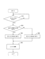
3.エンジン始動時の第1スイッチSW1の切り換え制御
また、車両ECU70は、エンジン始動時は、第1バッテリ50Aの温度Tに応じて、第1スイッチSW1のオン、オフを切り換える。図5を参照して、具体的に説明すると、車両ECU70は、イグニッションスイッチの状態を検出する処理を実行する(S10)。
3. 3. Switching control of the first switch SW1 when the engine is started The
そして、イグニッションスイッチのオンを検出すると、車両ECU70は、第1バッテリ50Aの組電池51Aの温度Tを、閾値Xと比較する処理を行う(S20)。尚、閾値Xは、第1バッテリ50Aが低温状態であるか否かを判別するものであり、一例として0℃である。
Then, when the ignition switch is detected to be turned on, the
車両ECU70は、第1バッテリ50Aの組電池51Aの温度Tが閾値X以上の場合、すなわち、第1バッテリ50Aが低温以外の場合、第1スイッチSW1に指令を与えて、第1スイッチSW1をオフ(開路)状態に制御する(S30)。これにより、エンジン始動装置10に対して第1バッテリ50Aだけが接続された状態となり、低温以外の場合、第1バッテリ50Aからクランキング電流が供給され、エンジン始動装置10は作動する(S50)。このように、低温以外の場合、第1スイッチSW1をオフして、第2バッテリ50Bをエンジン始動装置10から切り離すことで、エンジン始動に伴って、第2バッテリ50Bの電圧が変動することを抑制でき、電気負荷30や車両ECU70に対して安定した電源を供給することが出来る。
The
尚、第1バッテリ50Aの容量は40Ahであり、汎用の鉛バッテリに比べて容量が少ないが、リチウムイオン二次電池は内部抵抗が小さいことから、容量が少なくても、エンジン始動に必要なクランキング電流を放電することが出来、第1バッテリ50Aだけで、エンジン始動が可能である。
The capacity of the
一方、車両ECU70は、第1バッテリ50Aの組電池51Aの温度Tが閾値Xよりも低い場合、すなわち、第1バッテリ50Aが低温の場合、第1スイッチSW1に指令を与えて、第1スイッチSW1をオン(閉路)状態に制御する(S40)。これにより、エンジン始動装置10に対して2つのバッテリ50A、50Bが並列に接続された状態となる。そのため、2つのバッテリ50A、50Bからクランキング電流が供給され、エンジン始動装置10は作動する(S50)。
On the other hand, when the temperature T of the assembled
リチウムイオン二次電池は、低温状態では、内部抵抗が大きくなることから、第1バッテリ50Aだけでは、エンジン始動性が低下する恐れがある。しかし、本実施形態では、2つのバッテリ50A、50Bを並列に接続して、エンジンの始動に必要なクランキング電流を2つのバッテリ50A、50Bで分担する。そのため、第1バッテリ50Aだけでクランキング電流を負担する場合に比べて、エンジン始動性が向上し、低温時でも、常温時と同等の始動性を確保することが出来る。
Since the internal resistance of the lithium ion secondary battery increases in a low temperature state, the engine startability may decrease with the
4.効果説明
本実施形態の電源装置Sは、第1バッテリ50A、第2バッテリ50Bの双方ともリン酸鉄系のリチウムイオン二次電池53A、53Bであり、SOC−OCV特性にプラトー領域Pを有している。プラトー領域P内では、2つのバッテリ間にSOC差があっても、2つのバッテリ間の電圧差Va−Vbは小さい。そのため、第1スイッチSW1をオフからオンに切り換える時に、バッテリ間の電圧差Va−Vbにより、第1スイッチSW1に大きな電流(横流)が抑えることが出来る。尚、横流とは、電圧差Va−Vbにより、2つのバッテリ間に流れる電流を意味する。
4. Explanation of Effect The power supply device S of the present embodiment is an iron phosphate-based lithium ion
また、車両ECU70は、低温状態(T<X)でのエンジン始動時は、第1スイッチSW1をオンして2つのバッテリ50A、50Bを並列接続し、エンジン始動に必要なクランキング電流を2つのバッテリ50A、50Bで分担する。そのため、第1バッテリ50Aだけでクランキング電流を負担する場合に比べて、エンジンの始動性が向上し、通常時と同等の始動性を確保することが出来る。
Further, when the
また、車両ECU70は、低温以外の状態(T≧X)でのエンジン始動時は、第1スイッチSW1をオフしてエンジン始動装置10から第2バッテリ50Bを切り離す。そのため、エンジン始動に伴って、第2バッテリ50Bの電圧が変動することを抑制でき、電気負荷30や車両ECU70に対して、電圧変動の小さい安定した電源を供給することが出来る。
Further, when the engine is started in a state other than low temperature (T ≧ X), the
また、本実施形態の電源装置Sは、第1バッテリ50Aの実容量が40Ah、第2バッテリ50Bの実容量が20Ahであり、2つのバッテリ50A、50Bの実容量が異なっている。実容量の異なる2つのバッテリ50A、50Bが切り離された状態で使用されていると、2つのバッテリ間に電圧差Va−Vbが生じる場合がある。実容量の異なるバッテリ50A、50Bを組み合わせた電源装置Sに対して、本技術(バッテリの蓄電素子に「SOC−OCV特性に平坦な領域を有する素子」を使用する技術)を適用することで、2つのバッテリ間の電圧差Va−Vbを抑えることが可能となる。そのため、電圧差Va−Vbを考慮することなく、第1スイッチSW1の切り換えを常時行うことが可能となる。
<他の実施形態>
本発明は上記記述及び図面によって説明した実施形態に限定されるものではなく、例えば次のような実施形態も本発明の技術的範囲に含まれる。
(1)本実施形態では、バッテリ50A、50Bを組電池51A、51Bで構成して例を示したが、バッテリ50A、50Bを単セル、例えば、1つのリチウムイオン二次電池53A、53Bで構成してもよい。
Further, in the power supply device S of the present embodiment, the actual capacity of the
<Other Embodiments>
The present invention is not limited to the embodiments described in the above description and drawings, and for example, the following embodiments are also included in the technical scope of the present invention.
(1) In the present embodiment, the
(2)本実施形態では、リチウムイオン二次電池53A、53Bの活物質を正極はリン酸鉄リチウム、負極はグラファイトとした。リチウムイオン二次電池53A、53Bは、SOC−OCV特性に平坦な領域(プラトー領域)を有する蓄電素子であればよく、活物質の種類は、実施形態の例に限定されない。例えば、正極活物質をマンガン酸リチウム、負極活物質をチタン酸リチウムとしてもよい。尚、SOC−OCV特性に平坦な領域を持つ蓄電素子であれば、リチウムイオン二次電池以外の二次電池を使用することも可能である。
(2) In the present embodiment, the active materials of the lithium ion
(3)また、リチウムイオン二次電池53A、53Bの正極活物質種と負極活物質種がそれぞれ同一である場合、SOC−OCV特性がほぼ一致し、電圧差が生じ難い。そのため、2つのリチウムイオン二次電池53A、53Bの正極活物質種と負極活物質種をそれぞれ同一とすることが好ましい。尚、活物質種としては、正極であれば、リン酸鉄リチウム、マンガン酸リチウムのいずれかから選択し、負極であれば、グラファイト、チタン酸リチウムのうちいずれかを選択するとよい。
(3) Further, when the positive electrode active material type and the negative electrode active material type of the lithium ion
(4)本実施形態では、バッテリ50A、50Bの使用範囲Wの全体がプラトー領域Pに重なる例を示したが、バッテリ50A、50Bの使用範囲Wのうち、少なくとも一部が、プラトー領域Pに重なる関係でもよい。この場合、電流積算法などにより、各バッテリ50A、50BのSOC値を求め、2つのバッテリ50A、50Bがいずれも、プラトー領域Pに含まれている時に、第1スイッチSW1の切り換えを行うとよい。
(4) In the present embodiment, an example is shown in which the entire usage range W of the
(5)本実施形態では、第1スイッチSW1を、バッテリの外部に設けた構成としたが、図6に示すように、第1スイッチSW1をバッテリに内蔵するようにしてもよい。尚、図6において、バッテリ150Aに内蔵したスイッチSW1a、バッテリ150Bに内蔵したスイッチSW1bが、図1の第1スイッチSW1の機能を果たしている。
(5) In the present embodiment, the first switch SW1 is provided outside the battery, but as shown in FIG. 6, the first switch SW1 may be built in the battery. In FIG. 6, the switch SW1a built in the
(6)本実施形態では、スイッチ制御部の一例として車両ECU70を例示したが、車両ECU70とは別に、スイッチ制御部を専用に設けるようにしてもよい。また、スイッチ制御部の機能を、第1バッテリ50Aの監視部60Aや第2バッテリ50Bの監視部60Bに負担させる構成にしてもよい。
(6) In the present embodiment, the
(7)本実施形態では、閾値Xを0℃としたが、0℃以外の温度でもよい。 (7) In the present embodiment, the threshold value X is set to 0 ° C., but a temperature other than 0 ° C. may be used.
(8)本実施形態では、エンジン始動時に、第1バッテリ50Aが低温の場合、具体的には、第1バッテリ50Aの温度Tが閾値Xより低い場合(S20:NO)、第1スイッチSW1をオンして2つのバッテリ50A、50Bを並列に接続した(S40)。エンジン始動時に2つのバッテリ50A、50Bを並列に接続するかどうかを判断する条件は、第1バッテリ50Aの温度Tに限定されるものではなく、温度と相関性のある条件あれば、他の条件を適用してもよい。例えば、エンジン始動時に、第1バッテリ50Aの内部抵抗が所定の閾値より大きい場合や、第1バッテリ50Aのバッテリ電圧Vaが所定の閾値より低い場合など、第1バッテリ50Aだけではエンジン始動性が低下し易い場合に、第1スイッチSW1をオンして2つのバッテリ50A、50Bを並列に接続してもよい。
(8) In the present embodiment, when the temperature T of the
(9)また、2つのバッテリ50A、50Bを並列に接続するかどうかを判断する条件は、必ずしも温度と相関性がある条件に限定されるものではなく、例えば、バッテリの劣化と相関性のある条件を用いてもよい。例えば、エンジン始動時に、第1バッテリ50Aの劣化による内部抵抗の増加分が所定の閾値より大きい場合など、第1バッテリ50Aだけではエンジン始動性が低下し易い場合に、第1スイッチSW1をオンして2つのバッテリ50A、50Bを並列に接続してもよい。
(9) Further, the condition for determining whether or not the two
10...エンジン始動装置
20...オルタネータ
30...車両ECU
50A...第1バッテリ(本発明の「第1蓄電装置」の一例)
50B...第2バッテリ(本発明の「第2蓄電装置」の一例)
51A、51B...組電池
53A...リチウムイオン二次電池(本発明の「第1蓄電素子」の一例)
53B...リチウムイオン二次電池(本発明の「第2蓄電素子」の一例)
55...電流センサ
60A、60B...監視部
70...車両ECU(本発明の「スイッチ制御部」の一例)
SW1...第1スイッチ(本発明の「スイッチ」の一例)
SW2...第2スイッチ
S...電源装置
10 ...
50A ... 1st battery (an example of the "first power storage device" of the present invention)
50B ... Second battery (an example of the "second power storage device" of the present invention)
51A, 51B ... assembled
53B ... Lithium ion secondary battery (an example of the "second power storage element" of the present invention)
55 ...
SW1 ... 1st switch (an example of the "switch" of the present invention)
SW2 ... 2nd switch S ... Power supply
Claims (7)
第1蓄電素子を有する第1蓄電装置と、
第2蓄電素子を有する第2蓄電装置と、
前記第1蓄電装置と前記第2蓄電装置を並列に接続した状態と切り離した状態とに切り換えるスイッチと、
スイッチ制御部と、を備え、
前記第1蓄電素子と前記第2蓄電素子はSOC−OCV特性に平坦な領域を有する蓄電素子であり、
前記スイッチ制御部は、前記スイッチのオフからオンへの切り換えを、前記第1蓄電素子と前記第2蓄電素子が前記SOC−OCV特性で平坦な領域に含まれている時に、実行する、車両の電源装置。 It ’s a vehicle power supply.
A first power storage device having a first power storage element and
A second power storage device having a second power storage element and
A switch that switches between a state in which the first power storage device and the second power storage device are connected in parallel and a state in which the second power storage device is disconnected.
Equipped with a switch control unit
The first power storage element and the second power storage element are power storage elements having a flat region in SOC-OCV characteristics.
The switch control unit executes switching from off to on of the switch when the first power storage element and the second power storage element are included in a flat region with the SOC-OCV characteristics of the vehicle. Power supply.
前記第1蓄電装置はエンジン始動装置に接続され、
前記スイッチ制御部は、エンジン始動時に、所定の条件を満たす場合、前記スイッチをオンして、前記第1蓄電装置と前記第2蓄電装置を並列に接続する、車両の電源装置。 The vehicle power supply according to claim 1.
The first power storage device is connected to the engine starting device and is connected to the engine starting device.
The switch control unit is a vehicle power supply device that turns on the switch and connects the first power storage device and the second power storage device in parallel when a predetermined condition is satisfied when the engine is started.
前記所定の条件を満たす場合とは、前記第1蓄電素子の温度が閾値より低い場合、前記第1蓄電素子の内部抵抗が閾値よりも高い場合、前記第1蓄電素子の電圧値が閾値よりも低い場合のいずれかの場合である、車両の電源装置。 The vehicle power supply according to claim 2.
When the predetermined condition is satisfied, when the temperature of the first power storage element is lower than the threshold value, when the internal resistance of the first power storage element is higher than the threshold value, the voltage value of the first power storage element is higher than the threshold value. Vehicle power supply, which is one of the lower cases.
前記第2蓄電装置は、前記エンジン始動装置とは異なる電気負荷に接続され、
前記スイッチ制御部は、エンジン始動時に、前記所定の条件を満たさない場合、前記スイッチをオフして、前記第1蓄電装置と前記第2蓄電装置とを切り離す、車両の電源装置。 The vehicle power supply according to claim 2 or 3.
The second power storage device is connected to an electric load different from that of the engine starting device.
The switch control unit is a vehicle power supply device that turns off the switch and disconnects the first power storage device and the second power storage device when the engine starts and does not satisfy the predetermined conditions.
前記第1蓄電素子の正極活物質種と第2蓄電素子の正極活物質種とが同一であり、かつ第1蓄電素子の負極活物質種と第2蓄電素子の負極活物質種とが同一である、車両の電源装置。 The vehicle power supply device according to any one of claims 1 to 4.
The positive electrode active material type of the first power storage element and the positive electrode active material type of the second power storage element are the same, and the negative electrode active material type of the first power storage element and the negative electrode active material type of the second power storage element are the same. There is a vehicle power supply.
前記第1蓄電装置と前記第2蓄電装置は実容量が異なる、車両の電源装置。 The vehicle power supply according to any one of claims 1 to 5.
A vehicle power supply device in which the first power storage device and the second power storage device have different actual capacities.
前記スイッチは、前記第1蓄電装置と前記第2蓄電装置の正極同士を接続する通電ライン上において、前記通電ラインに対する前記第1蓄電装置の接続点と前記第2蓄電装置の接続点の間に位置する、車両の電源装置。 The switch is placed between the connection point of the first power storage device and the connection point of the second power storage device with respect to the power supply line on the power supply line connecting the positive electrodes of the first power storage device and the second power storage device. Located in the vehicle power supply.
Priority Applications (4)
| Application Number | Priority Date | Filing Date | Title |
|---|---|---|---|
| JP2016196273A JP6902201B2 (en) | 2016-10-04 | 2016-10-04 | Vehicle power supply |
| CN201710910040.3A CN107895819B (en) | 2016-10-04 | 2017-09-29 | Power supply device for vehicle |
| US15/723,997 US11235682B2 (en) | 2016-10-04 | 2017-10-03 | Power supply device for vehicle |
| DE102017217574.5A DE102017217574A1 (en) | 2016-10-04 | 2017-10-04 | POWER SUPPLY FOR A VEHICLE |
Applications Claiming Priority (1)
| Application Number | Priority Date | Filing Date | Title |
|---|---|---|---|
| JP2016196273A JP6902201B2 (en) | 2016-10-04 | 2016-10-04 | Vehicle power supply |
Publications (2)
| Publication Number | Publication Date |
|---|---|
| JP2018060641A JP2018060641A (en) | 2018-04-12 |
| JP6902201B2 true JP6902201B2 (en) | 2021-07-14 |
Family
ID=61623756
Family Applications (1)
| Application Number | Title | Priority Date | Filing Date |
|---|---|---|---|
| JP2016196273A Active JP6902201B2 (en) | 2016-10-04 | 2016-10-04 | Vehicle power supply |
Country Status (4)
| Country | Link |
|---|---|
| US (1) | US11235682B2 (en) |
| JP (1) | JP6902201B2 (en) |
| CN (1) | CN107895819B (en) |
| DE (1) | DE102017217574A1 (en) |
Families Citing this family (8)
| Publication number | Priority date | Publication date | Assignee | Title |
|---|---|---|---|---|
| DE102018100746B4 (en) * | 2018-01-15 | 2024-01-11 | Dr. Ing. H.C. F. Porsche Aktiengesellschaft | Fault-tolerant battery storage system and on-board electrical system |
| EP3626505A1 (en) | 2018-09-18 | 2020-03-25 | KNORR-BREMSE Systeme für Nutzfahrzeuge GmbH | A system and method for providing redundant electric power |
| JP7056513B2 (en) | 2018-10-26 | 2022-04-19 | トヨタ自動車株式会社 | Battery control device |
| JP7284911B2 (en) * | 2019-03-06 | 2023-06-01 | 株式会社Gsユアサ | Storage device management device, system, and storage device management method |
| JP7421871B2 (en) | 2019-05-24 | 2024-01-25 | 株式会社Subaru | Vehicle power supply device |
| DE102020004356A1 (en) * | 2020-07-20 | 2020-10-08 | Daimler Ag | Method for determining a state of charge in a battery-operated vehicle with several batteries during operation of the vehicle, as well as battery-operated vehicle with several batteries |
| CN112083339A (en) * | 2020-09-13 | 2020-12-15 | 孟锦涛 | Battery charge state monitoring method |
| DE102022202063A1 (en) | 2022-03-01 | 2023-09-07 | Volkswagen Aktiengesellschaft | Vehicle electrical system for supplying voltage to at least one safety-relevant consumer, method for operating a vehicle electrical system, and energy storage device for use in a vehicle electrical system |
Family Cites Families (19)
| Publication number | Priority date | Publication date | Assignee | Title |
|---|---|---|---|---|
| WO1990016090A1 (en) * | 1989-06-12 | 1990-12-27 | Globe-Union Inc. | Switched dual battery system |
| US5986431A (en) * | 1996-11-18 | 1999-11-16 | Gnb Technologies, Inc. | Battery power system for vehicles |
| JP2004025979A (en) | 2002-06-25 | 2004-01-29 | Shin Kobe Electric Mach Co Ltd | Power supply system for travelling vehicle |
| JP4772137B2 (en) * | 2009-06-02 | 2011-09-14 | トヨタ自動車株式会社 | Control device for battery-powered equipment |
| EP2272722B1 (en) | 2009-07-01 | 2015-04-08 | Denso Corporation | Power source apparatus for vehicle |
| JP5428708B2 (en) | 2009-09-29 | 2014-02-26 | 株式会社デンソー | In-vehicle power supply |
| CN102044902A (en) * | 2009-10-20 | 2011-05-04 | 徐辛 | Lithium-ion automobile starting storage battery with super capacitor function |
| TWI416841B (en) * | 2010-06-10 | 2013-11-21 | Wistron Corp | Electricity storing device and electronic device |
| JP5664491B2 (en) * | 2011-08-03 | 2015-02-04 | 株式会社デンソー | Battery control device |
| JP6032473B2 (en) | 2011-09-09 | 2016-11-30 | 株式会社Gsユアサ | State management device and method for equalizing storage elements |
| US8805926B2 (en) * | 2011-09-29 | 2014-08-12 | Intel Corporation | Common idle state, active state and credit management for an interface |
| US9382892B2 (en) | 2012-10-29 | 2016-07-05 | Sanyo Electric Co., Ltd. | Vehicle performing idling stop |
| JP6003743B2 (en) * | 2013-03-21 | 2016-10-05 | 株式会社オートネットワーク技術研究所 | Power supply |
| JP6113587B2 (en) * | 2013-06-28 | 2017-04-12 | 三洋電機株式会社 | Power supply |
| JP6219655B2 (en) | 2013-09-27 | 2017-10-25 | 株式会社Subaru | Vehicle power supply |
| JP6119584B2 (en) | 2013-12-04 | 2017-04-26 | 株式会社デンソー | Battery control device |
| JP2015118060A (en) * | 2013-12-20 | 2015-06-25 | 株式会社豊田自動織機 | State-of-charge estimation apparatus and state-of-charge estimation method |
| JP6307992B2 (en) * | 2014-04-03 | 2018-04-11 | 株式会社デンソー | Power supply |
| WO2015189902A1 (en) | 2014-06-09 | 2015-12-17 | 日産自動車株式会社 | Vehicle electrical circuit |
-
2016
- 2016-10-04 JP JP2016196273A patent/JP6902201B2/en active Active
-
2017
- 2017-09-29 CN CN201710910040.3A patent/CN107895819B/en active Active
- 2017-10-03 US US15/723,997 patent/US11235682B2/en active Active
- 2017-10-04 DE DE102017217574.5A patent/DE102017217574A1/en active Pending
Also Published As
| Publication number | Publication date |
|---|---|
| US20180093581A1 (en) | 2018-04-05 |
| DE102017217574A1 (en) | 2018-04-05 |
| JP2018060641A (en) | 2018-04-12 |
| CN107895819A (en) | 2018-04-10 |
| US11235682B2 (en) | 2022-02-01 |
| CN107895819B (en) | 2022-06-03 |
Similar Documents
| Publication | Publication Date | Title |
|---|---|---|
| JP6902201B2 (en) | Vehicle power supply | |
| JP6540781B2 (en) | Power storage device | |
| JP5471083B2 (en) | In-vehicle power supply | |
| JP6155569B2 (en) | Power system | |
| JP4745879B2 (en) | Hybrid vehicle control system, hybrid vehicle control method, and vehicle storage battery control system | |
| JP2007325458A (en) | Vehicular battery pack uniformizing system | |
| JP6802723B2 (en) | Power storage device and power storage control method | |
| US10971767B2 (en) | Charge voltage controller for energy storage device, energy storage apparatus, battery charger for energy storage device, and charging method for energy storage device | |
| JP7010187B2 (en) | Vehicle power system control method, vehicle power system | |
| JP2007018871A (en) | Control device of secondary battery and system carrying this device | |
| CN111746278B (en) | Battery controller and battery control method | |
| JP6791345B2 (en) | Operation mode control device, mobile body | |
| JP7211217B2 (en) | Power system, power system control method | |
| JP2017143635A (en) | Power source system for vehicle | |
| JP5772615B2 (en) | Power storage system | |
| JPWO2020085097A1 (en) | Battery control device | |
| WO2021205872A1 (en) | Method for controlling power supply system of moving body, power supply system of moving body, and power storage device | |
| JP2023179282A (en) | Control apparatus, control method, and control program | |
| JP2021078237A (en) | Control method of electrical power system of mobile body, and electrical power system of mobile body | |
| JP5257173B2 (en) | In-vehicle power supply |
Legal Events
| Date | Code | Title | Description |
|---|---|---|---|
| A621 | Written request for application examination |
Free format text: JAPANESE INTERMEDIATE CODE: A621 Effective date: 20190916 |
|
| A977 | Report on retrieval |
Free format text: JAPANESE INTERMEDIATE CODE: A971007 Effective date: 20200730 |
|
| A131 | Notification of reasons for refusal |
Free format text: JAPANESE INTERMEDIATE CODE: A131 Effective date: 20200903 |
|
| A601 | Written request for extension of time |
Free format text: JAPANESE INTERMEDIATE CODE: A601 Effective date: 20201029 |
|
| A521 | Request for written amendment filed |
Free format text: JAPANESE INTERMEDIATE CODE: A523 Effective date: 20201210 |
|
| TRDD | Decision of grant or rejection written | ||
| A01 | Written decision to grant a patent or to grant a registration (utility model) |
Free format text: JAPANESE INTERMEDIATE CODE: A01 Effective date: 20210520 |
|
| A61 | First payment of annual fees (during grant procedure) |
Free format text: JAPANESE INTERMEDIATE CODE: A61 Effective date: 20210602 |
|
| R150 | Certificate of patent or registration of utility model |
Ref document number: 6902201 Country of ref document: JP Free format text: JAPANESE INTERMEDIATE CODE: R150 |