JP6900946B2 - Engineering support system and engineering support method - Google Patents
Engineering support system and engineering support method Download PDFInfo
- Publication number
- JP6900946B2 JP6900946B2 JP2018241195A JP2018241195A JP6900946B2 JP 6900946 B2 JP6900946 B2 JP 6900946B2 JP 2018241195 A JP2018241195 A JP 2018241195A JP 2018241195 A JP2018241195 A JP 2018241195A JP 6900946 B2 JP6900946 B2 JP 6900946B2
- Authority
- JP
- Japan
- Prior art keywords
- model
- semantic model
- semantic
- drawings
- unit
- Prior art date
- Legal status (The legal status is an assumption and is not a legal conclusion. Google has not performed a legal analysis and makes no representation as to the accuracy of the status listed.)
- Active
Links
Images


Classifications
-
- G—PHYSICS
- G05—CONTROLLING; REGULATING
- G05B—CONTROL OR REGULATING SYSTEMS IN GENERAL; FUNCTIONAL ELEMENTS OF SUCH SYSTEMS; MONITORING OR TESTING ARRANGEMENTS FOR SUCH SYSTEMS OR ELEMENTS
- G05B19/00—Programme-control systems
- G05B19/02—Programme-control systems electric
- G05B19/18—Numerical control [NC], i.e. automatically operating machines, in particular machine tools, e.g. in a manufacturing environment, so as to execute positioning, movement or co-ordinated operations by means of programme data in numerical form
- G05B19/4097—Numerical control [NC], i.e. automatically operating machines, in particular machine tools, e.g. in a manufacturing environment, so as to execute positioning, movement or co-ordinated operations by means of programme data in numerical form characterised by using design data to control NC machines, e.g. CAD/CAM
-
- G—PHYSICS
- G06—COMPUTING; CALCULATING OR COUNTING
- G06F—ELECTRIC DIGITAL DATA PROCESSING
- G06F16/00—Information retrieval; Database structures therefor; File system structures therefor
- G06F16/20—Information retrieval; Database structures therefor; File system structures therefor of structured data, e.g. relational data
- G06F16/21—Design, administration or maintenance of databases
-
- G—PHYSICS
- G06—COMPUTING; CALCULATING OR COUNTING
- G06F—ELECTRIC DIGITAL DATA PROCESSING
- G06F16/00—Information retrieval; Database structures therefor; File system structures therefor
- G06F16/20—Information retrieval; Database structures therefor; File system structures therefor of structured data, e.g. relational data
- G06F16/24—Querying
- G06F16/245—Query processing
- G06F16/2452—Query translation
- G06F16/24522—Translation of natural language queries to structured queries
-
- G—PHYSICS
- G06—COMPUTING; CALCULATING OR COUNTING
- G06F—ELECTRIC DIGITAL DATA PROCESSING
- G06F30/00—Computer-aided design [CAD]
-
- G—PHYSICS
- G06—COMPUTING; CALCULATING OR COUNTING
- G06F—ELECTRIC DIGITAL DATA PROCESSING
- G06F30/00—Computer-aided design [CAD]
- G06F30/10—Geometric CAD
-
- G—PHYSICS
- G06—COMPUTING; CALCULATING OR COUNTING
- G06V—IMAGE OR VIDEO RECOGNITION OR UNDERSTANDING
- G06V30/00—Character recognition; Recognising digital ink; Document-oriented image-based pattern recognition
- G06V30/40—Document-oriented image-based pattern recognition
- G06V30/42—Document-oriented image-based pattern recognition based on the type of document
- G06V30/422—Technical drawings; Geographical maps
-
- G—PHYSICS
- G05—CONTROLLING; REGULATING
- G05B—CONTROL OR REGULATING SYSTEMS IN GENERAL; FUNCTIONAL ELEMENTS OF SUCH SYSTEMS; MONITORING OR TESTING ARRANGEMENTS FOR SUCH SYSTEMS OR ELEMENTS
- G05B2219/00—Program-control systems
- G05B2219/30—Nc systems
- G05B2219/31—From computer integrated manufacturing till monitoring
- G05B2219/31342—Design of process control system
-
- G—PHYSICS
- G05—CONTROLLING; REGULATING
- G05B—CONTROL OR REGULATING SYSTEMS IN GENERAL; FUNCTIONAL ELEMENTS OF SUCH SYSTEMS; MONITORING OR TESTING ARRANGEMENTS FOR SUCH SYSTEMS OR ELEMENTS
- G05B2219/00—Program-control systems
- G05B2219/30—Nc systems
- G05B2219/42—Servomotor, servo controller kind till VSS
- G05B2219/42155—Model
-
- G—PHYSICS
- G06—COMPUTING; CALCULATING OR COUNTING
- G06F—ELECTRIC DIGITAL DATA PROCESSING
- G06F2111/00—Details relating to CAD techniques
-
- G—PHYSICS
- G06—COMPUTING; CALCULATING OR COUNTING
- G06F—ELECTRIC DIGITAL DATA PROCESSING
- G06F2111/00—Details relating to CAD techniques
- G06F2111/02—CAD in a network environment, e.g. collaborative CAD or distributed simulation
-
- G—PHYSICS
- G06—COMPUTING; CALCULATING OR COUNTING
- G06F—ELECTRIC DIGITAL DATA PROCESSING
- G06F2111/00—Details relating to CAD techniques
- G06F2111/12—Symbolic schematics
-
- G—PHYSICS
- G06—COMPUTING; CALCULATING OR COUNTING
- G06F—ELECTRIC DIGITAL DATA PROCESSING
- G06F2111/00—Details relating to CAD techniques
- G06F2111/20—Configuration CAD, e.g. designing by assembling or positioning modules selected from libraries of predesigned modules
-
- G—PHYSICS
- G06—COMPUTING; CALCULATING OR COUNTING
- G06F—ELECTRIC DIGITAL DATA PROCESSING
- G06F2113/00—Details relating to the application field
- G06F2113/14—Pipes
-
- G—PHYSICS
- G06—COMPUTING; CALCULATING OR COUNTING
- G06T—IMAGE DATA PROCESSING OR GENERATION, IN GENERAL
- G06T17/00—Three dimensional [3D] modelling, e.g. data description of 3D objects
-
- G—PHYSICS
- G06—COMPUTING; CALCULATING OR COUNTING
- G06V—IMAGE OR VIDEO RECOGNITION OR UNDERSTANDING
- G06V10/00—Arrangements for image or video recognition or understanding
- G06V10/70—Arrangements for image or video recognition or understanding using pattern recognition or machine learning
- G06V10/74—Image or video pattern matching; Proximity measures in feature spaces
Description
本発明は、エンジニアリング支援システム及びエンジニアリング支援方法に関する。 The present invention relates to an engineering support system and an engineering support method.
従来から、プラントや工場等(以下、これらを総称する場合には、単に「プラント」という)においては、工業プロセスにおける各種の状態量(例えば、圧力、温度、流量等)を制御するプロセス制御システムが構築されており、高度な自動操業が実現されている。具体的には、プロセス制御システムの核をなすコントローラが、複数のセンサ(流量計や温度計等)の検出結果を取得し、この検出結果に応じてアクチュエータ(バルブ等)の操作量を求め、この操作量に応じてアクチュエータを操作することによって、上述した各種の状態量が制御されている。 Conventionally, in plants, factories, etc. (hereinafter, collectively referred to as "plants"), a process control system that controls various state quantities (for example, pressure, temperature, flow rate, etc.) in an industrial process. Has been constructed, and highly automatic operation has been realized. Specifically, the controller, which is the core of the process control system, acquires the detection results of a plurality of sensors (flow meter, thermometer, etc.), and obtains the operation amount of the actuator (valve, etc.) according to the detection results. By operating the actuator according to this manipulated variable, the various state quantities described above are controlled.
このようなプロセス制御システムの構築、運用、保守、改修等におけるエンジニアリングは、多種多様の図面及び仕様書等(以下、「図面類」という)を用いて、複数のエンジニアによって行われるのが殆どである。上記の図面類としては、例えば、P&ID(Piping and Instrument Diagram:配管系統図)、PFD(Process Flow Diagram:プロセスフロー図)、機器リスト、機器設定情報、CAD(Computer Aided Design)図面、制御ロジック図、シミュレーションモデル、グラフィック図面等が挙げられる。尚、上記の「エンジニアリング」とは、システムの構築、変更、保守等に関わる作業をいう。 In most cases, engineering in the construction, operation, maintenance, repair, etc. of such a process control system is performed by a plurality of engineers using a wide variety of drawings and specifications (hereinafter referred to as "drawings"). is there. Examples of the above drawings include P & ID (Piping and Instrument Diagram), PFD (Process Flow Diagram), device list, device setting information, CAD (Computer Aided Design) drawing, and control logic diagram. , Simulation model, graphic drawing, etc. The above-mentioned "engineering" refers to work related to system construction, modification, maintenance, and the like.
プロセス制御システムは、複数の構成要素が密接に関連しており、一部の構成要素が変更されると、他の構成要素の変更も必要になる場合がある。このため、プロセス制御システムのエンジニアリングを効率的に行うには、プロセス制御システムの実態(実際の構成や実際の設定等)が反映された図面類を、エンジニアリングに携わるエンジニアの間で共有することが重要になる。以下の特許文献1には、プラントの保全管理業務を一元的に管理することが可能な保全管理システムが開示されている。また、以下の特許文献2には、プラント設備に係る改造工事の実施状況を管理することにより、正確で迅速に実施状況を把握して作業員の支援をする保守情報管理支援装置が開示されている。
In a process control system, multiple components are closely related, and when one component is changed, it may be necessary to change other components as well. Therefore, in order to efficiently engineer the process control system, it is necessary to share drawings that reflect the actual conditions of the process control system (actual configuration, actual settings, etc.) among the engineers involved in the engineering. It will be important. The following
ところで、プロセス制御システムのエンジニアリングを効率的に行うためには、上述の通り、プロセス制御システムの実態が反映された必要な図面類を、エンジニアリングに携わるエンジニアの間で、利用可能な形で共有されることが理想的である。しかしながら、実際には、プロセス制御システムの実態が反映された図面類が、エンジニアリングに携わるエンジニアの間で十分に共有されておらず、再利用にも手間がかかり、現状では作業効率が良いとは言い難い状況である。 By the way, in order to efficiently engineer a process control system, as described above, necessary drawings reflecting the actual state of the process control system are shared in a form that can be used among engineers involved in engineering. Is ideal. However, in reality, drawings that reflect the actual state of the process control system are not sufficiently shared among engineers involved in engineering, and it takes time to reuse them, so it is said that work efficiency is good at present. It's a difficult situation to say.
本発明は上記事情に鑑みてなされたものであり、エンジニアリングで用いられる各種情報を関連付けて統合することにより、作業効率を大幅に改善することができるエンジニアリング支援システム及びエンジニアリング支援方法を提供することを目的とする。 The present invention has been made in view of the above circumstances, and provides an engineering support system and an engineering support method capable of significantly improving work efficiency by associating and integrating various information used in engineering. The purpose.
上記課題を解決するために、本発明の一態様によるエンジニアリング支援システムは、プロセス制御システムのエンジニアリングを支援するエンジニアリング支援システム(1)であって、前記プロセス制御システムのエンジニアリングで用いられる図面類(FG)を、該図面類に含まれる要素を示す第1情報と要素同士の関係を示す第2情報とによって表現した意味モデル(M)に変換する変換部(10)と、複数の前記意味モデルの類似度に基づいて、複数の前記意味モデルを結合した結合意味モデル(CM)を生成する結合意味モデル生成部(31)と、を備える。 In order to solve the above problems, the engineering support system according to one aspect of the present invention is an engineering support system (1) that supports the engineering of the process control system, and the drawings (FG) used in the engineering of the process control system. ) Is converted into a semantic model (M) represented by the first information indicating the elements included in the drawings and the second information indicating the relationship between the elements, and the conversion unit (10) of the plurality of the semantic models. A combined semantic model generation unit (31) that generates a combined semantic model (CM) that combines a plurality of the semantic models based on the degree of similarity is provided.
また、本発明の一態様によるエンジニアリング支援システムは、前記類似度を算出する類似度算出部(32)を備えており、前記結合意味モデル生成部が、前記類似度算出部で算出された前記類似度に基づいて、前記結合意味モデルを生成する。 Further, the engineering support system according to one aspect of the present invention includes a similarity calculation unit (32) for calculating the similarity, and the combination meaning model generation unit calculates the similarity calculated by the similarity calculation unit. The combined semantic model is generated based on the degree.
また、本発明の一態様によるエンジニアリング支援システムは、前記類似度が、複数の前記意味モデルに含まれる前記第1情報の類似性の度合いと前記第2情報の類似性の度合いとを示すものである。 Further, in the engineering support system according to one aspect of the present invention, the similarity indicates the degree of similarity of the first information and the degree of similarity of the second information included in the plurality of semantic models. is there.
また、本発明の一態様によるエンジニアリング支援システムは、前記第1情報には、前記要素の名称を示す情報と、前記要素の特質を示す情報とが含まれる。 Further, in the engineering support system according to one aspect of the present invention, the first information includes information indicating the name of the element and information indicating the characteristics of the element.
また、本発明の一態様によるエンジニアリング支援システムは、前記結合意味モデルから、指示に応じた抽出意味モデルを抽出する意味モデル情報抽出部(34)を備えており、前記変換部が、前記意味モデル情報抽出部で抽出された前記抽出意味モデル(EM)を前記図面類に変換する。 Further, the engineering support system according to one aspect of the present invention includes a semantic model information extraction unit (34) that extracts an extraction semantic model according to an instruction from the combined semantic model, and the conversion unit is the semantic model. The extraction meaning model (EM) extracted by the information extraction unit is converted into the drawings.
また、本発明の一態様によるエンジニアリング支援システムは、前記類似度の算出規則を格納する第1データベース(33)を備えており、前記類似度算出部が、前記第1データベースに格納された前記算出規則に従って、複数の前記意味モデルについての前記類似度を算出する。 Further, the engineering support system according to one aspect of the present invention includes a first database (33) for storing the calculation rule of the similarity, and the similarity calculation unit stores the calculation in the first database. According to the rules, the similarity for a plurality of the semantic models is calculated.
また、本発明の一態様によるエンジニアリング支援システムは、前記図面類と前記意味モデルとの変換規則を格納する第2データベース(12)を備えており、前記変換部が、前記第2データベースに格納された前記変換規則に従って、前記図面類を前記意味モデルに変換し、前記意味モデルを前記図面類に変換する。 Further, the engineering support system according to one aspect of the present invention includes a second database (12) for storing conversion rules between the drawings and the semantic model, and the conversion unit is stored in the second database. According to the conversion rule, the drawings are converted into the semantic model, and the semantic model is converted into the drawings.
また、本発明の一態様によるエンジニアリング支援システムは、前記結合意味モデルから前記意味モデルを抽出するための抽出規則を格納する第3データベース(35)を備えており、前記意味モデル情報抽出部が、前記第3データベースに格納された前記抽出規則に従って、指示された範囲における指示された種類の前記図面類を作成するために必要な前記意味モデルを抽出する。 Further, the engineering support system according to one aspect of the present invention includes a third database (35) for storing extraction rules for extracting the semantic model from the combined semantic model, and the semantic model information extraction unit can be used by the semantic model information extraction unit. According to the extraction rule stored in the third database, the semantic model necessary for creating the drawings of the specified type in the specified range is extracted.
また、本発明の一態様によるエンジニアリング支援システムは、指示に基づいて、前記意味モデルの修正、前記意味モデルの修正の支援、又は複数の前記意味モデル若しくは複数の前記結合意味モデルの比較を行うアプリケーション部(40)を更に備える。 Further, the engineering support system according to one aspect of the present invention is an application that modifies the semantic model, supports the modification of the semantic model, or compares a plurality of the semantic models or a plurality of the combined semantic models based on instructions. A unit (40) is further provided.
また、本発明の一態様によるエンジニアリング支援システムは、前記意味モデル及び前記結合意味モデルを格納する格納部(20)を更に備える。 Further, the engineering support system according to one aspect of the present invention further includes a storage unit (20) for storing the semantic model and the combined semantic model.
本発明の一態様によるエンジニアリング支援方法は、プロセス制御システムのエンジニアリングを支援するエンジニアリング支援方法であって、前記プロセス制御システムのエンジニアリングで用いられる図面類(FG)を、該図面類に含まれる要素を示す第1情報と要素同士の関係を示す第2情報とによって表現した意味モデル(M)に変換する第1変換ステップ(S11)と、複数の前記意味モデルの類似度に基づいて、複数の前記意味モデルを結合した結合意味モデル(CM)を生成する結合意味モデル生成ステップ(S12)と、を有する。 The engineering support method according to one aspect of the present invention is an engineering support method that supports the engineering of a process control system, and includes drawings (FG) used in the engineering of the process control system and elements included in the drawings. Based on the first conversion step (S11) for converting into the semantic model (M) represented by the first information shown and the second information indicating the relationship between the elements, and the similarity of the plurality of the semantic models, the plurality of the above It has a combined semantic model generation step (S12) for generating a combined semantic model (CM) in which the semantic models are combined.
また、本発明の一態様によるエンジニアリング支援方法は、前記結合意味モデルから、指示に応じた抽出意味モデルを抽出する意味モデル情報抽出ステップ(S13)と、前記意味モデル情報抽出ステップで抽出された前記抽出意味モデルを前記図面類に変換する第2変換ステップ(S14)と、を有する。 Further, the engineering support method according to one aspect of the present invention includes a semantic model information extraction step (S13) for extracting an extracted semantic model according to an instruction from the combined semantic model, and the semantic model information extraction step extracted in the semantic model information extraction step. It has a second conversion step (S14) for converting the extraction meaning model into the drawings.
本発明によれば、エンジニアリングで用いられる各種情報を関連付けて統合することにより、作業効率を大幅に改善することができる、という効果がある。 According to the present invention, there is an effect that work efficiency can be significantly improved by associating and integrating various information used in engineering.
以下、図面を参照して本発明の実施形態によるエンジニアリング支援システム及びエンジニアリング支援方法について詳細に説明する。以下では、まず本発明の実施形態の概要について説明し、続いて本発明の実施形態の詳細について説明する。 Hereinafter, the engineering support system and the engineering support method according to the embodiment of the present invention will be described in detail with reference to the drawings. Hereinafter, the outline of the embodiment of the present invention will be described first, and then the details of the embodiment of the present invention will be described.
〔概要〕
本発明の実施形態は、エンジニアリングで用いられる各種情報を関連付けて統合することに関し、少なくとも一部を自動的に行うことにより、作業効率を大幅に改善することを可能にするものである。ここで、エンジニアリングで用いられる図面類は、前述の通り、P&ID及びPFD等をはじめとして多種多様なものが存在する。また、プロセス制御システムのエンジニアリングでは、構成要素毎にエンジニアの作業時の視点や切り口が異なることから必要となる図面類も異なる。
〔Overview〕
An embodiment of the present invention makes it possible to significantly improve work efficiency by automatically performing at least a part of associating and integrating various information used in engineering. Here, as described above, there are a wide variety of drawings used in engineering, including P & ID and PFD. Further, in the engineering of a process control system, the drawings required are also different because the viewpoints and cuts of the engineer's work are different for each component.
例えば、操作監視端末(HMI:Human Machine Interface)、制御装置、ネットワーク等のエンジニアリングを行うエンジニアは、論理的接続(機能間の接続)の視点で作業を行うため、論理的接続が示された図面類が必要になる。これに対し、計装保全や設備保全を行うエンジニアは、物理的接続(機器間の接続)の視点で作業を行うため、物理的接続が示された図面類が必要になる。 For example, an engineer who designs an operation monitoring terminal (HMI: Human Machine Interface), a control device, a network, etc. works from the viewpoint of a logical connection (connection between functions), so a drawing showing the logical connection. Kind is needed. On the other hand, engineers who perform instrumentation maintenance and equipment maintenance work from the viewpoint of physical connection (connection between devices), so drawings showing physical connection are required.
このように、多種多様の図面類が存在し、且つ、エンジニアリングに携わるエンジニア毎に必要となる図面類が異なる場合があることから、単純に図面類を一元的に管理しただけでは、エンジニアリングに携わるエンジニアの間で図面類が、利用可能な形で共有されているとは言い難い。なぜならば、あるエンジニアが必要とする図面類が更新されたとしても、他のエンジニアが必要とする図面類が必ずしも更新されるとは限らないからである。このような状況では、一部の構成要素の変更が他の構成要素に及ぼす影響を直接的に把握することができない場合が多い。 In this way, there are a wide variety of drawings, and the drawings required for each engineer involved in engineering may differ. Therefore, simply managing the drawings centrally is involved in engineering. It is hard to say that drawings are shared in a usable form among engineers. This is because even if the drawings required by one engineer are updated, the drawings required by another engineer are not necessarily updated. In such situations, it is often not possible to directly understand the impact of changes in some components on other components.
また、プラントの稼働期間は、例えば30年以上と長い。その間に、プラントの設備の改変や増築によるプロセス制御システムの設定変更や追加等が発生することも想定される。その際、プロセス制御システムの設定変更や追加等のエンジニアリングに用いるエンジニアリングツール自体が変更されることも有り得る。例えば、エンジニアリングツールの機能向上が行われたり、別のエンジニアリングツールに変更されたりすることがある。このような場合には、エンジニアリングツールの変更前の情報を、変更後で共有することが難しくなる。 In addition, the operating period of the plant is as long as 30 years or more, for example. In the meantime, it is expected that the setting of the process control system will be changed or added due to the modification or extension of the plant equipment. At that time, the engineering tool itself used for engineering such as changing or adding the setting of the process control system may be changed. For example, an engineering tool may be improved or changed to another engineering tool. In such a case, it becomes difficult to share the information before the change of the engineering tool after the change.
また、エンジニアリングに用いるエンジニアリングツールの特性や、エンジニアリングを行うエンジニアの知識や経験等に応じて、作成される図面類には癖や個性等が生ずる。このため、エンジニアは、自身が作成等に関与していない図面類や、使用経験の無いエンジニアリングツールで作成された図面類を正確に理解するのは困難である。その結果、図面類を作成したエンジニア以外のエンジニア等が、既存の図面類を活用しようとしても困難が伴う。 In addition, depending on the characteristics of the engineering tool used for engineering and the knowledge and experience of the engineer who performs the engineering, the drawings to be created have habits and individuality. For this reason, it is difficult for an engineer to accurately understand drawings that he / she is not involved in, or drawings that are created by an engineering tool that he / she has no experience in using. As a result, it is difficult for engineers other than the engineer who created the drawings to utilize the existing drawings.
本発明の実施形態では、プロセス制御システムのエンジニアリングで用いられる図面類を、図面類に含まれる要素を示す第1情報と要素同士の関係を示す第2情報とによって表現した意味モデルに変換する。そして、複数の意味モデルの類似度に基づいて、複数の意味モデルを結合した結合意味モデルを生成する。このように、エンジニアリングで用いられる各種情報(図面類)を関連付けて統合することにより、作業効率を大幅に改善することを可能にしている。 In the embodiment of the present invention, the drawings used in the engineering of the process control system are converted into a semantic model represented by the first information indicating the elements included in the drawings and the second information indicating the relationship between the elements. Then, based on the similarity of the plurality of semantic models, a combined semantic model in which the plurality of semantic models are combined is generated. In this way, by associating and integrating various information (drawings) used in engineering, it is possible to greatly improve work efficiency.
〔実施形態〕
〈エンジニアリング支援システムの要部構成〉
図1は、本発明の一実施形態によるエンジニアリング支援システムの要部構成を示すブロック図である。図1に示す通り、本実施形態のエンジニアリング支援システム1は、変換部10、意味モデルデータベース(DB)20(格納部)、結合意味モデル管理部30、及びアプリケーション部40を備える。かかる構成のエンジニアリング支援システム1は、プロセス制御システム(図示省略)のエンジニアリングで用いられる図面類FGの管理を行うことで、プロセス制御システム(図示書略)のエンジニアリングを支援する。尚、ここでいう図面類FGの管理とは、複数の図面類FGを上記の結合意味モデルとして管理することに加え、結合意味モデルから必要な情報を抽出して新たな図面類FGを作成することを意味する。
[Embodiment]
<Structure of key parts of engineering support system>
FIG. 1 is a block diagram showing a main configuration of an engineering support system according to an embodiment of the present invention. As shown in FIG. 1, the
エンジニアリング支援システム1は、端末装置TMからの指示に従って、図面類FGの管理を行うものとする。端末装置TMは、有線又は無線でエンジニアリング支援システム1に接続され、ユーザによって操作される装置である。この端末装置TMは、キーボードやポインティングデバイス等の入力装置、及び液晶表示装置等の表示装置を備える。端末装置TMは、ユーザが入力装置を操作して入力した指示を、エンジニアリング支援システム1に送信する。また、端末装置TMは、エンジニアリング支援システム1から送信されてくる各種情報を表示装置に表示する。
The
ここで、エンジニアリング支援システム1で管理される図面類FGは、エンジニアリングで用いられる任意の図面及び仕様書等である。例えば、P&ID、PFD、機器リスト、機器設定情報、制御ロジック図、シミュレーションモデル、グラフィック図面、CAD図面等(3D図面を含む)が挙げられる。尚、図面類FGは、データであっても良く、データの読み取りが可能であれば紙媒体に印刷されたものであっても良い。また、エンジニアリング支援システム1が管理する図面類FGの数や種類は任意である。
Here, the drawings FG managed by the
変換部10は、プロセス制御システムのエンジニアリングで用いられる図面類FGを、図面類FGに含まれる要素を示す情報(第1情報)と要素同士の関係を示す情報(第2情報)とによって表現した意味モデルMに変換する。例えば、プラントに設けられた複数の機器が図面類FGの要素として含まれている場合に、変換部10は、それらの機器を示す情報と、それらの機器の接続関係を示す情報とによって表現した意味モデルMを生成する。
The
上記の機器を示す情報には、機器の名称を示す情報と、機器の特質(プロパティ)を示す情報とが含まれる。例えば、特質には、機器固有の特徴・性質(例えば、タンク等の容量や配管の径、機器のメーカや対応方式等)以外に、システムの構成やシミュレーションの条件に応じて各機器に設定される設定値、パラメータ等も含み得る。尚、意味モデルMは、所謂オントロジー技術を用いて生成されても良い。また、変換部10は、抽出意味モデルEM(図3参照)を図面類FGに変換することも可能である。
The information indicating the above-mentioned device includes information indicating the name of the device and information indicating the characteristics (property) of the device. For example, in addition to the characteristics and properties unique to the equipment (for example, the capacity of the tank, the diameter of the pipe, the manufacturer of the equipment, the corresponding method, etc.), the characteristics are set for each equipment according to the system configuration and simulation conditions. Settings, parameters, etc. may also be included. The semantic model M may be generated by using a so-called ontology technique. Further, the
図2は、本発明の一実施形態によるエンジニアリング支援システムが備える変換部の要部構成を示すブロック図である。図2に示す通り、変換部10は、コンバータ11、変換ルールデータベース12(第2データベース)、及びパーツライブラリデータベース13を備える。
FIG. 2 is a block diagram showing a main configuration of a conversion unit included in the engineering support system according to the embodiment of the present invention. As shown in FIG. 2, the
コンバータ11は、変換ルールデータベース12に格納されている変換ルールに従って、図面類FGを意味モデルMに変換する。例えば、コンバータ11は、図面類FG1を意味モデルM1に変換し、図面類FG2を意味モデルM2に変換する。また、コンバータ11は、変換ルールデータベース12に格納されている変換ルールに従って、抽出意味モデルEM(図3参照)を図面類FGに変換する。
The
変換ルールデータベース12は、図面類FGと意味モデルM(抽出意味モデルEM)との変換ルール(変換規則)を格納する。この変換ルールデータベース12は、例えば、上記の変換ルールを、図面類FGの種類毎に格納する。この変換ルールデータベース12には、図面類FGの作成及び変更に用いられるエンジニアリングツールやベンダの違いによる変換方法の違いを補正する補正ルールが格納されていても良い。尚、図面類FGの種類によっては、IEC61360−2(使用機器リスト)、IEC62832(機器設定情報)等の標準化規格に合わせた形式で意味モデルMを生成するための変換ルールを含めても良い。
The
パーツライブラリデータベース13は、コンバータ11が抽出意味モデルEM(図3参照)を図面類FGに変換する場合に、変換に必要となる固有のパーツを格納する。ここで、意味モデルMは、いわば図面類FGを意味づけして抽象化したものであるため、抽象化された意味モデルMから具体的な図面類FGを作成する場合には、具体的な情報(パーツ)を補う必要がある。パーツライブラリデータベース13は、このような具体的な固有のパーツを格納する。例えば、パーツライブラリデータベース13は、グラフィック定義に関わる表示パーツ(例えば、タンクやバルブを模式的に示すアイコン)等を格納する。尚、同一の図面類FGであっても、使用するエンジニアツールによって使用するパーツが異なる場合がある。このため、パーツは、エンジニアリングツール毎に複数用意されていても良い。
The
意味モデルデータベース20は、変換部10で変換された意味モデルM、及び意味モデルMを結合して得られる結合意味モデルCM(詳細は後述する)を、再利用のために、或いは履歴として格納する。尚、意味モデルデータベース20は、抽出意味モデルEM(図3参照)を格納しても良い。
The
結合意味モデル管理部30は、意味モデルデータベース20に格納された結合意味モデルCMの管理を行う。具体的に、結合意味モデル管理部30は、変換部10で変換された複数の意味モデルMを結合して結合意味モデルCMを生成する。ここで、結合意味モデル管理部30は、複数の意味モデルMの類似度に基づいて、結合意味モデルCMを生成する。また、結合意味モデル管理部30は、結合意味モデルCMから、端末装置TMからの指示に応じた抽出意味モデルEMを抽出する。
The combined semantic
図3は、本発明の一実施形態によるエンジニアリング支援システムが備える結合意味モデル管理部の要部構成を示すブロック図である。図3に示す通り、結合意味モデル管理部30は、結合意味モデル生成部31、意味モデル情報抽出部34、及び抽出ルールデータベース35(第3データベース)を備える。
FIG. 3 is a block diagram showing a main configuration of a combined meaning model management unit included in the engineering support system according to the embodiment of the present invention. As shown in FIG. 3, the combined semantic
結合意味モデル生成部31は、複数の意味モデルMを結合して結合意味モデルCMを生成する。具体的に、結合意味モデル生成部31は、マッチング部32(類似度算出部)及びマッチングルールデータベース33(第1データベース)を備えており、マッチング部32で算出される類似度に基づいて、複数の意味モデルMを結合して結合意味モデルCMを生成する。尚、結合意味モデルCMの生成例については、複数の意味モデルMの類似度の算出例と同様に、後述する。
The combined semantic
マッチング部32は、複数の意味モデルMの類似度を算出する。具体的に、マッチング部32は、マッチングルールデータベース33に格納されたマッチングルールに従って、上記の類似度を算出する。マッチングルールデータベース33は、上記類似度を算出するために必要となるマッチングルール(算出規則)を格納する。
The matching
ここで、意味モデルMは、前述の通り、図面類FGに含まれる要素を示す情報(第1情報)と要素同士の関係を示す情報(第2情報)とによって表現されるものである。このため、マッチングルールには、複数の意味モデルMに含まれる第1情報の類似性の度合いを算出するためのルールと、第2情報の類似性の度合いを算出するためのルールとが含まれる。従って、マッチング部32で算出される類似度は、複数の意味モデルMに含まれる第1情報の類似度の度合いと第2情報の類似度の度合いとを示すものである。尚、複数の意味モデルMの類似度の算出例については後述する。
Here, as described above, the semantic model M is represented by information indicating the elements included in the drawings FG (first information) and information indicating the relationship between the elements (second information). Therefore, the matching rule includes a rule for calculating the degree of similarity of the first information included in the plurality of semantic models M and a rule for calculating the degree of similarity of the second information. .. Therefore, the similarity calculated by the matching
意味モデル情報抽出部34は、抽出ルールデータベース35に格納された抽出ルールに従って、結合意味モデルCMから、端末装置TMからの指示に応じた抽出意味モデルEMを抽出する。ここで、意味モデル情報抽出部34が、抽出意味モデルEMを抽出する上で必要な指示は、作成すべき図面類FGの種類(抽出する意味モデルの種類)を特定する指示と、作成すべき図面類FGの範囲を特定する指示である。このため、意味モデル情報抽出部34は、結合意味モデルCMから、指示された範囲における指示された種類の図面類FGを作成するために必要な抽出意味モデルEMを抽出する。尚、抽出意味モデルEMを抽出する上で必要な指示として、作成すべき図面類FGの種類に加えて条件が必要になる場合もある。抽出意味モデルEMの抽出例については後述する。
The semantic model
抽出ルールデータベース35は、結合意味モデルCMから抽出意味モデルEMを抽出するための抽出ルール(抽出規則)を格納する。抽出ルールデータベース35に格納される抽出ルールは、図面類FGを作成するために結合意味モデルCMからどのような情報を抽出する必要があるかを規定したものである。抽出ルールデータベース35は、抽出ルールを、図面類FGの種類毎に格納する。
The
アプリケーション部40は、端末装置TMからの指示に基づいて、エンジニアリング支援システム1が図面類FGの管理を行う上で有用な機能を提供する。例えば、アプリケーション部40は、意味モデルM、結合意味モデルCM、及び抽出意味モデルEMを修正する機能、並びに意味モデルM、結合意味モデルCM、及び抽出意味モデルEMの修正を支援する機能を提供する。また、アプリケーション部40は、複数の意味モデルMを比較する機能、複数の結合意味モデルCMを比較する機能、及び複数の抽出意味モデルEMを比較する機能を提供する。
The
図4は、本発明の一実施形態によるエンジニアリング支援システムが備えるアプリケーション部の要部構成を示すブロック図である。図4に示す通り、アプリケーション部40は、ルールデータベース修正部41、意味モデル修正部42、類似パターン抽出部43、修正候補提示部44、意味モデル比較部45、及び変換支援部46を備える。
FIG. 4 is a block diagram showing a configuration of a main part of an application unit included in an engineering support system according to an embodiment of the present invention. As shown in FIG. 4, the
ルールデータベース修正部41は、端末装置TMからの指示に基づいて、変換部10に設けられた変換ルールデータベース12、結合意味モデル管理部30に設けられたマッチングルールデータベース33、及び結合意味モデル管理部30に設けられた抽出ルールデータベース35の修正を行う。意味モデル修正部42は、端末装置TMからの指示に基づいて、意味モデルデータベース20に格納された意味モデルM及び抽出意味モデルEMの修正を行う。尚、ルールデータベース修正部41や意味モデル修正部42による修正は、例えば図3に示すマッチング部32によって複数の意味モデルMの類似度が算出される場合、或いは意味モデル情報抽出部34によって抽出意味モデルEMの抽出が行われる場合等に行われる。
The rule
類似パターン抽出部43は、端末装置TMから指示された図面類FGや意味モデルMについて、その周囲も含め、類似するパターンを、意味モデルデータベース20を検索して抽出する。例えば、修正が必要な意味モデルMがあるとすると、類似パターン抽出部43は、その意味モデルMと類似するパターンを、意味モデルデータベース20から検索する。尚、類似するパターンとは、当該意味モデルM及びその周囲に含まれる要素(ノード)や、要素(ノード)同士の関係性が類似した部分(パターン)のことである。
The similar
修正候補提示部44は、変換された意味モデルMや結合された結合意味モデルCM等(以下、「意味モデルM等」と略記する)に修正が必要な箇所が存在する場合に、その修正が必要な意味モデルM等やその中の要修正箇所を、自動的に、或いは、エンジニアの指示に応じ、抽出して提示する。また、修正候補提示部44は、エンジニアによる意味モデルM等の修正を補助するために、類似パターン抽出部43によって、提示された意味モデルM等やその中の提示箇所(要修正箇所)に類似するパターンを、システム内に記憶されているモデルから抽出し、リファレンスとして提示(表示)しても良い。
The correction
その際に、修正候補提示部44は、より修正すべき意味モデルM等と類似度の高いパターン(類似度がより大きなパターン)を提示し、類似度の高い順番を付与して提示するようにしても良い。修正候補提示部44によって提示される修正候補、及び、その修正のためのリファレンスとなる類似パターンは、端末装置TMに表示される。エンジニアは、修正対象と類似するリファレンスの意味モデルを比較対象として提示されることで、要修正部位の修正が容易になる。
At that time, the correction
意味モデル比較部45は、端末装置TMからの指示に基づいて、複数の結合意味モデルCMを比較して差分を抽出する。意味モデル比較部45の抽出結果は、端末装置TMに送信される。意味モデル比較部45は、最新の意味モデルMと過去の意味モデルMとの比較を行っても良い。
The semantic
変換支援部46は、変換部10で変換(図面類FGから意味モデルMへの変換、抽出意味モデルEMから図面類FGへの変換の双方を含む)が行われる場合の変換処理を支援する。例えば、変換支援部46は、変換部10で変換が行われる場合に、要素の過不足や新規の要素等の検出、変換エラー等の検出を行って、その検出結果を端末装置TMに出力する。
The
意味モデルMの修正が必要な場合は、ユーザは端末装置TMを介し、意味モデルMを修正する。それが新たなルールとなる場合(現ルールを修正すべき場合)は、その修正ルールを、ルールデータベース修正部41が、変換ルールデータベース12に反映する。このような修正が行われることで、検出された新規の要素、要素の過不足、変換エラー等が解消されることになる。尚、ユーザにより、変換ルールデータベース12が修正された場合には、修正された(新たな)ルールを、対象の意味モデルMに対して自動的に適用させてもよい。この場合、意味モデルM及び変換ルールデータベース12の何れか一方が修正されれば、何れか他方にもその修正が自動的に反映されることになる。
When it is necessary to modify the semantic model M, the user modifies the semantic model M via the terminal device TM. When it becomes a new rule (when the current rule should be modified), the modification rule is reflected in the
〈エンジニアリング支援システムの基本動作例〉
図5は、本発明の一実施形態によるエンジニアリング支援システムの基本動作例を示すフローチャートである。尚、図5に示すフローチャートは、例えば端末装置TMから送信された処理開始の指示が、エンジニアリング支援システム1で受信されることにより開始される。尚、以下では、図6に示す通り、P&ID(図面類FG11)及びPFD(図面類FG12)からシミュレーションモデル(図面類FG13)を作成する場合を例に挙げて説明する。図6は、本発明の一実施形態における基本動作例を説明するための図である。
<Basic operation example of engineering support system>
FIG. 5 is a flowchart showing a basic operation example of the engineering support system according to the embodiment of the present invention. The flowchart shown in FIG. 5 is started when, for example, the processing start instruction transmitted from the terminal device TM is received by the
図5に示すフローチャートが開始されると、まず、図面類を意味モデルに変換する処理が変換部10で行われる(ステップS11:第1変換ステップ)。具体的には、変換部10の変換ルールデータベース12に格納された変換ルールに従って、図面類を意味モデルに変換し、変換した意味モデルを意味モデルデータベース20に格納する処理が、変換部10に設けられたコンバータ11によって行われる。
When the flowchart shown in FIG. 5 is started, first, the
より具体的には、P&ID(図面類FG11)がコンバータ11に読み込まれるとともに、P&IDを意味モデルに変換するための変換ルールが変換ルールデータベース12からコンバータ11に読み込まれる。そして、読み込んだ変換ルールに従って、P&ID(図面類FG11)をP&ID意味モデルM11に変換する処理がコンバータ11で行われる。同様に、PFD(図面類FG12)がコンバータ11に読み込まれるとともに、PFDを意味モデルに変換するための変換ルールが変換ルールデータベース12からコンバータ11に読み込まれる。そして、読み込んだ変換ルールに従って、PFD(図面類FG12)をPFD意味モデルM12に変換する処理がコンバータ11で行われる。
More specifically, the P & ID (drawings FG11) is read into the
図7は、本発明の一実施形態で管理される図面類であるP&ID及びその意味モデルを説明するための図である。図7(a)に例示する図面類FG11であるP&IDは、タンク(Tank)101、バルブ102、及び反応器(Reactor)103が配管111〜114によって接続された図である。具体的には、タンク101の上流側に配管111が接続され、タンク101とバルブ102との間に配管112が接続され、バルブ102と反応器103との間に配管113が接続され、反応器103の下流側に配管114が接続されている。尚、タンク101、バルブ102、及び反応器103は、直感的且つ容易に把握できるような記号で示されている。
FIG. 7 is a diagram for explaining P & ID, which is drawings managed in one embodiment of the present invention, and a semantic model thereof. P & ID, which is the drawings FG11 illustrated in FIG. 7A, is a diagram in which a
また、図7(a)に例示するP&IDには、タンク101、バルブ102、及び反応器103、並びに配管111〜114の名称が含まれている。具体的に、タンク101の名称は「E−1」であり、バルブ102の名称は「V−1」であり、反応器103の名称は「E−2」である。配管111〜114の名称は「P−1」〜「P−4」である。尚、図7(a)では図示していないが、P&IDには、P&IDに含まれる要素(プラントに設けられる機器、装置、設備等を含む)の特質(プロパティ)を示す情報が含まれる。
Further, the P & ID illustrated in FIG. 7A includes the names of the
図7(b)に例示するP&ID意味モデルM11は、図7(a)に例示するP&IDから生成されたものである。図7(b)に示す通り、P&ID意味モデルM11において、タンク101、バルブ102、及び反応器103、並びに配管111〜114は、抽象化されてノードとして表現されている。各ノードには、そのノードを示す情報(第1情報)として、名称を示す情報と特質(プロパティ)を示す情報とが紐付けられる。また、各ノードには、タンク101、バルブ102、及び反応器103、並びに配管111〜114の接続関係を示す情報(第2情報)が紐付けられる。
The P & ID semantic model M11 illustrated in FIG. 7 (b) is generated from the P & ID illustrated in FIG. 7 (a). As shown in FIG. 7B, in the P & ID semantic model M11, the
例えば、タンク101を示すノードには、名称を示す情報(hasName)として「E−1」が紐付けられており、特質を示す情報(hasProperty)として「直径(Diameter)」及び「高さ(Height)」が紐付けられている。タンク101を示すノードには、接続先を示す情報(isconnectedto)として、配管112のノードを示す情報が紐付けられている。また、配管112を示すノードには、名称を示す情報(hasName)として「P−2」が紐付けられており、特質を示す情報(hasProperty)として「口径(Caliber)」及び「長さ(Length)」が紐付けられている。配管112を示すノードには、接続先を示す情報(isconnectedto)として、バルブ102のノードを示す情報が紐付けられている。
For example, the node indicating the
また、配管113を示すノードには、名称を示す情報(hasName)として「P−3」が紐付けられており、特質を示す情報(hasProperty)として「口径(Caliber)」及び「長さ(Length)」が紐付けられている。配管113を示すノードには、接続先を示す情報(isconnectedto)として、反応器103のノードを示す情報が紐付けられている。また、反応器103を示すノードには、名称を示す情報(hasName)として「E−2」が紐付けられているが、特質を示す情報(hasProperty)は紐付けられていない。これは、図7(a)に例示するP&IDに、反応器103の名称を示す情報は含まれているが、反応器103の特質を示す情報が含まれていないからである。反応器103を示すノードには、接続先を示す情報(isconnectedto)として、配管114のノードを示す情報が紐付けられている。
Further, "P-3" is associated with the node indicating the
図8は、本発明の一実施形態で管理される図面類であるPFD及びその意味モデルを説明するための図である。図8(a)に例示する図面類FG12であるPFDは、タンク101及び反応器103と、原料の流れを示すフロー121〜123とが示された図である。具体的には、タンク101の上流側にフロー121が示され、タンク101と反応器103との間にフロー122が示され、反応器103の下流側にフロー123が示されている。尚、PFDにおいて、タンク101及び反応器103は、P&IDと同様に、直感的且つ容易に把握できるような記号で示されている。また、PFDでは、フローが重要であることから、図7(a)に示すバルブ102及び配管111〜114は省略される。
FIG. 8 is a diagram for explaining PFD and its semantic model, which are drawings managed in one embodiment of the present invention. PFD, which is the drawings FG12 illustrated in FIG. 8A, is a diagram showing a
また、図8(a)に例示するPFDには、フロー121〜123の名称が含まれている。具体的に、フロー121の名称は「S−1」であり、フロー122の名称は「S−2」であり、フロー123の名称は「S−3」である。尚、図8(a)では図示していないが、PFDには、タンク101及び反応器103の名称も含まれている。また、PFDには、PFDに含まれる要素(プラントに設けられる機器、装置、設備等に加えてフロー等を含む)の特質(プロパティ)を示す情報が含まれる。
Further, the PFD illustrated in FIG. 8A includes the names of
図8(b)に例示するPFD意味モデルM12は、図8(a)に例示するPFDから生成されたものである。図8(b)に示す通り、PFD意味モデルM12において、タンク101及び反応器103、並びにフロー(Stream)121〜123は、抽象化されてノードとして表現されている。各ノードには、そのノードを示す情報(第1情報)として、名称を示す情報と特質(プロパティ)を示す情報とが紐付けられる。また、各ノードには、タンク101及び反応器103並びにフロー121〜123の関係を示す情報(第2情報)が紐付けられる。
The PFD semantic model M12 illustrated in FIG. 8 (b) is generated from the PFD illustrated in FIG. 8 (a). As shown in FIG. 8B, in the PFD semantic model M12, the
例えば、タンク101を示すノードには、名称を示す情報(hasName)及び特質を示す情報(hasProperty)は紐付けられていない。タンク101を示すノードには、接続先を示す情報(isconnectedto)として、フロー122のノードを示す情報が紐付けられている。また、フロー122を示すノードには、名称を示す情報(hasName)として「S−2」が紐付けられており、特質を示す情報(hasProperty)として「圧力値(Pressure Value)」及び「流量(Flow Rate)」が紐付けられている。フロー122を示すノードには、接続先を示す情報(isconnectedto)として、反応器103のノードを示す情報が紐付けられている。
For example, the node indicating the
また、反応器103を示すノードには、名称を示す情報(hasName)は紐付けられておらず、特質を示す情報(hasProperty)として「化学反応式(Chemical reaction formula)が紐付けられている。反応器103を示すノードには、接続先を示す情報(isconnectedto)として、フロー123のノードを示す情報が紐付けられている。
Further, the node indicating the
このように、P&ID(図面類FG11)を変換して得られるP&ID意味モデルM11、PFD(図面類FG12)を変換して得られるPFD意味モデルM12は何れも、図面類FG11,FG12に含まれる要素が抽象化されてノードとして表現されたものである。そして、各ノードには、そのノードを示す情報(第1情報)と、ノード同士の関係を示す情報(第2情報)とが紐付けられる。尚、これらの情報は、P&IDやPFDに含まれていない場合には、省略される場合もある。このように、異なる種類の図面類であっても、変換部10による変換によって生成される意味モデルは、図面類に含まれる要素を示す情報(第1情報)と要素同士の関係を示す情報(第2情報)とによって表現されたものとなる。
In this way, the P & ID semantic model M11 obtained by converting the P & ID (drawings FG11) and the PFD semantic model M12 obtained by converting the PFD (drawings FG12) are all elements included in the drawings FG11 and FG12. Is abstracted and expressed as a node. Then, each node is associated with information indicating the node (first information) and information indicating the relationship between the nodes (second information). If this information is not included in the P & ID or PFD, it may be omitted. As described above, even if the drawings are of different types, the semantic model generated by the conversion by the
尚、図7(b),図8(b)では、理解を容易にするために、P&ID意味モデルM11及びPFD意味モデルM12を、ノード及び各種情報が線(矢印線)で接続された図で表現している。しかしながら、これらP&ID意味モデルM11及びPFD意味モデルM12は、例えばHTML(Hyper Text Markup Language)、XML(eXtensible Markup Language等のマークアップ言語によって表現されていても良い。 In addition, in FIGS. 7 (b) and 8 (b), in order to facilitate understanding, the P & ID meaning model M11 and the PFD meaning model M12 are shown by connecting nodes and various information with lines (arrow lines). expressing. However, these P & ID meaning models M11 and PFD meaning models M12 may be expressed by markup languages such as HTML (Hyper Text Markup Language) and XML (eXtensible Markup Language).
また、図5に示すステップS11の処理が行われた場合には、必要に応じてエンジニアが生成された意味モデルを検証し、検証結果に応じて変換部10に設けられた変換ルールデータベース12の内容を修正するようにしてもよい。例えば、アプリケーション部40に設けられた変換支援部46の機能を利用して生成された意味モデルを必要に応じてエンジニアが検証し、ルールデータベース修正部41の機能を利用して変換ルールデータベース12の内容を修正することが可能である。
Further, when the process of step S11 shown in FIG. 5 is performed, the engineer verifies the generated semantic model as necessary, and the
次に、意味モデルを結合して結合意味モデルを生成する処理が、結合意味モデル管理部30で行われる(ステップS12:結合意味モデル生成ステップ)。具体的には、結合意味モデル管理部30のマッチングルールデータベース33に格納されたマッチングルールに従って、複数の意味モデルの類似度を算出する処理がマッチング部32で行われる。そして、マッチング部32で算出された類似度に基づいて、複数の意味モデルを結合して結合意味モデルを生成する処理が結合意味モデル生成部31で行われる。
Next, the process of combining the semantic models to generate the combined semantic model is performed by the combined semantic model management unit 30 (step S12: combined semantic model generation step). Specifically, the matching
より具体的には、P&ID意味モデルM11及びPFD意味モデルM12がマッチング部32に読み込まれるとともに、これらの意味モデルの類似度を算出するために必要なマッチングルールがマッチングルールデータベース33からマッチング部32に読み込まれる。そして、読み込んだマッチングルールに従って、P&ID意味モデルM11とPFD意味モデルM12との類似度を算出する処理がマッチング部32で行われる。その後、P&ID意味モデルM11及びPFD意味モデルM12が結合意味モデル生成部31に読み込まれるとともに、マッチング部32で算出された類似度が結合意味モデル生成部31に読み込まれる。そして、読み込んだ類似度に基づいて、P&ID意味モデルM11とPFD意味モデルM12とを結合して、結合意味モデルCM1を生成する処理が結合意味モデル生成部31で行われる。
More specifically, the P & ID semantic model M11 and the PFD semantic model M12 are read into the
図9は、本発明の一実施形態で生成される結合意味モデルを説明するための図である。図9に示す結合意味モデルCM1は、図7(b)に示すP&ID意味モデルM11と図8(b)に示すPFD意味モデルM12とから生成されたものである。図9を参照すると、結合意味モデルCM1において、タンク101、バルブ102、及び反応器103、並びに配管111〜114は、図7(b)に示すP&ID意味モデルM11と同様に表現されている。
FIG. 9 is a diagram for explaining a binding meaning model generated in one embodiment of the present invention. The combined meaning model CM1 shown in FIG. 9 is generated from the P & ID meaning model M11 shown in FIG. 7 (b) and the PFD meaning model M12 shown in FIG. 8 (b). Referring to FIG. 9, in the coupling semantic model CM1, the
ここで、図7(b)に示すP&ID意味モデルM11及び図8(b)に示すPFD意味モデルM12において、タンク101のノード及び反応器103のノードは共通する。このため、P&ID意味モデルM11に含まれるタンク101のノードと、PFD意味モデルM12に含まれるタンク101のノードとは類似性の度合いが高い。同様に、P&ID意味モデルM11に含まれる反応器103のノードと、PFD意味モデルM12に含まれる反応器103のノードとは類似性の度合いが高い。
Here, in the P & ID meaning model M11 shown in FIG. 7B and the PFD meaning model M12 shown in FIG. 8B, the node of the
また、図7(b)に示すP&ID意味モデルM11において、配管112のノード、バルブ102のノード、及び配管113のノードを1つのノードに見立てると、P&ID意味モデルM11におけるノードの並びは、PFD意味モデルM12におけるノードの並びと同様になる。このため、P&ID意味モデルM11に含まれるノードの並びと、PFD意味モデルM12に含まれるノードの並びとは類似性の度合いが高い。
Further, in the P & ID meaning model M11 shown in FIG. 7B, assuming that the node of the
上記の類似性の度合いに基づいて、P&ID意味モデルM11とPFD意味モデルM12とが結合意味モデル生成部31によって結合されることにより、図9に示す結合意味モデルCM1が生成される。例えば、P&ID意味モデルM11におけるタンク101のノードとPFD意味モデルM12におけるタンク101のノードとの類似性の度合いが一定以上に高ければ、結合意味モデル生成部31は、それらタンク101のノードを同一物と判定する。結合意味モデル生成部31は、P&ID意味モデルM11及びPFD意味モデルM12における反応器103のノードについても同様に判定する。
Based on the above degree of similarity, the P & ID meaning model M11 and the PFD meaning model M12 are combined by the combination meaning
一方、P&ID意味モデルM11においてタンク101のノードと反応器103のノードとの間に登場するバルブ102のノードは、PFD意味モデルM12には存在しない。しかしながら、同一物と判定された2つのノード(タンク101のノード及び反応器103のノード)の間に存在すること、全体的な(周囲のノードの)関係性、一致の度合から、バルブ102のノードの位置は、タンク101のノードと反応器103のノードとの間に特定される。尚、図9に例示する結合意味モデルCM1は、P&ID意味モデルM11及びPFD意味モデルM12に対し、以下に示す処理が結合意味モデル生成部31によって行われて生成されたものである。
On the other hand, the node of the
・P&ID意味モデルM11におけるタンク101のノードと、PFD意味モデルM12におけるタンク101のノードとを統合する処理
・P&ID意味モデルM11における反応器103のノードと、PFD意味モデルM12における反応器103のノードとを統合する処理
・P&ID意味モデルM11における配管111のノードと、PFD意味モデルM12におけるフロー121のノードとを統合する処理
・P&ID意味モデルM11における配管113のノードと、PFD意味モデルM12におけるフロー122のノードとを統合する処理
・P&ID意味モデルM11における配管114のノードと、PFD意味モデルM12におけるフロー123のノードとを統合する処理
-Process to integrate the node of the
図9に例示する結合意味モデルCM1は、いわば要素の数が相対的に少ないPFD意味モデルM12が、要素の数が相対的に多いP&ID意味モデルM11に統合されたものになっている。このため、図9に例示する結合意味モデルCM1では、PFD意味モデルM12におけるフロー121,122,123のノードが、P&ID意味モデルM11における配管111,113,114のノードにそれぞれ統合される。このため、結合意味モデルCM1には、PFD意味モデルM12におけるフロー121,122,123のノードは現れていない。
In the combined semantic model CM1 illustrated in FIG. 9, the PFD semantic model M12 having a relatively small number of elements is integrated with the P & ID semantic model M11 having a relatively large number of elements. Therefore, in the combined meaning model CM1 illustrated in FIG. 9, the nodes of the
尚、上記の統合にあたり、結合意味モデルCM1には、結合したそれぞれの意味モデルが有する情報を共に保有させても良い。例えば、P&IDでの“配管”という情報と、PFDでの“フロー”という情報とを共に結合意味モデルCM1に保有させるといった具合である。 In the above integration, the combined semantic model CM1 may have the information possessed by each of the combined semantic models. For example, the information "piping" in P & ID and the information "flow" in PFD are both stored in the combined meaning model CM1.
複数の意味モデルに含まれるノードを統合する場合には、上述の通り、1つの意味モデルに含まれるノードを他の意味モデルに含まれるノードに統合する方法で統合しても良く、他の方法により統合しても良い。例えば、複数の意味モデルに含まれるノードのうち、類似する意味を有するノードを、それらを包含する意味を有する新たなノードに統合する方法で統合しても良い。例えば、P&ID意味モデルM11に含まれる配管111のノード及びPFD意味モデルM12に含まれるフロー121のノードを、「タンク入力」の意味を有する新たなノードに統合するといった具合である。
When integrating the nodes included in a plurality of semantic models, as described above, the nodes included in one semantic model may be integrated with the nodes included in the other semantic models, and other methods may be used. May be integrated by. For example, among the nodes included in a plurality of semantic models, nodes having similar meanings may be integrated by a method of integrating them into a new node having a meaning including them. For example, the node of the
尚、図9では、理解を容易にするために、結合意味モデルCM1を、図7(b),図8(b)と同様に、ノード及び各種情報が線(矢印線)で接続された図で表現している。しかしながら、結合意味モデルCM1は、例えばHTML、XML等のマークアップ言語によって表現されていても良い。 In addition, in FIG. 9, in order to facilitate understanding, the connection meaning model CM1 is connected by a line (arrow line) in the same manner as in FIGS. 7 (b) and 8 (b). It is expressed by. However, the combined meaning model CM1 may be expressed by a markup language such as HTML or XML.
また、図5に示すステップS12の処理が行われた場合には、生成された結合意味モデルCM1を必要に応じてエンジニアが検証し、検証結果に応じて結合意味モデル管理部30に設けられたマッチングルールデータベース33の内容を修正するようにしてもよい。例えば、アプリケーション部40に設けられたルールデータベース修正部41の機能を利用して、マッチングルールデータベース33の内容を修正することが可能である。
Further, when the process of step S12 shown in FIG. 5 is performed, the engineer verifies the generated join meaning model CM1 as necessary, and the join meaning
ここで、結合意味モデルCM1は、プラントに設けられた設備を対象とするユニット単位、プラントの一部の領域を対象とするエリア単位、或いはプラント全体を対象とするプラント単位で生成することが望ましい。このような単位で結合意味モデルCM1を生成することで、エンジニアリングに携わる複数のエンジニアが必要とする情報(図面類)を、意味づけして集約することができる。 Here, it is desirable that the combined meaning model CM1 is generated in a unit unit that targets the equipment provided in the plant, an area unit that targets a part of the area of the plant, or a plant unit that targets the entire plant. .. By generating the combined meaning model CM1 in such a unit, the information (drawings) required by a plurality of engineers involved in engineering can be meaningfully aggregated.
次に、結合意味モデルから、指示に応じた意味モデルを抽出する処理が、意味モデル情報抽出部34で行われる(ステップS13:意味モデル情報抽出ステップ)。具体的には、結合意味モデル管理部30の抽出ルールデータベース35に格納された抽出ルールに従って、結合意味モデルCM1から、端末装置TMからの指示に応じた抽出意味モデルEMを抽出する処理が意味モデル情報抽出部34で行われる。
Next, the semantic model
より具体的には、端末装置TMからは、作成すべきシミュレーションモデル(図面類FG13)を特定する指示と、作成すべきシミュレーションモデル(図面類FG13)の範囲を特定する指示(例えば、範囲として、○○ユニットを対象として指示する等)が送信されてくる。これらの指示がエンジニアリング支援システム1で受信されると、シミュレーションモデル抽出意味モデルEM1を抽出するために必要となる抽出ルールが抽出ルールデータベース35から意味モデル情報抽出部34に読み込まれる。尚、上記のシミュレーションモデル抽出意味モデルEM1は、端末装置TMから指示されたシミュレーションモデル(図面類FG13)を作成するために必要な意味モデルである。そして、読み込んだ抽出ルールに従って、結合意味モデルCM1から、指示された範囲における指示されたシミュレーションモデル(図面類FG13)を作成するために必要なシミュレーションモデル抽出意味モデルEM1を抽出する処理が意味モデル情報抽出部34で行われる。
More specifically, from the terminal device TM, an instruction for specifying the simulation model (drawings FG13) to be created and an instruction for specifying the range of the simulation model (drawings FG13) to be created (for example, as a range). (Instructions for XX units, etc.) will be sent. When these instructions are received by the
図10は、本発明の一実施形態で結合意味モデルから抽出される抽出意味モデル及びその抽出意味モデルから生成される図面類を説明するための図である。図10(a)を参照すると、抽出されたシミュレーションモデル抽出意味モデルEM1において、タンク101、バルブ102、及び反応器103は、図9に示す結合意味モデルCM1と同様に表現されているものの、配管111〜114は、フロー131〜134として表現されている。これは、シミュレーションモデルにおいては、原料が流れる配管111〜114として表現するよりも、原料の流れを示すフロー131〜134として表現した方が適切だからである。
FIG. 10 is a diagram for explaining an extracted meaning model extracted from a combined meaning model in one embodiment of the present invention and drawings generated from the extracted meaning model. Referring to FIG. 10A, in the extracted simulation model extraction meaning model EM1, the
尚、図10(a)に示す例では、原料の流れを示すフロー131〜134を示すノードには、配管111〜114の名称を示す情報(hasName)が紐付けられている。例えば、フロー131を示すノードには、配管111の名称を示す情報(hasName)である「P−1」が紐付けられており、フロー132を示すノードには、配管112の名称を示す情報(hasName)である「P−2」が紐付けられている。これは、結合意味モデルCM1に含まれている配管111〜114を、フロー131〜134として表現したためである。
In the example shown in FIG. 10A, information (hasName) indicating the names of the
また、抽出されたシミュレーションモデル抽出意味モデルEM1では、フロー131の上流側に境界条件(Boundary Condition)130を示すノードが追加されている。これは、シミュレーションモデルを用いてシミュレーションを行う場合に、フロー131として供給される原料の条件を規定する必要があるためである。境界条件130を示すノードには、特質を示す情報(hasProperty)として「圧力値(Pressure Value)」及び「原料組成(Composition)」が紐付けられている。
Further, in the extracted simulation model extraction meaning model EM1, a node indicating a
尚、図10(a)では、理解を容易にするために、シミュレーションモデル抽出意味モデルEM1を、図7(b),図8(b),図9と同様に、ノード及び各種情報が線(矢印線)で接続された図で表現している。しかしながら、シミュレーションモデル抽出意味モデルEM1は、例えばHTML、XML等のマークアップ言語によって表現されていても良い。 In FIG. 10A, in order to facilitate understanding, the simulation model extraction meaning model EM1 is drawn with lines (nodes and various information) as in FIGS. 7 (b), 8 (b), and 9. It is represented by a diagram connected by an arrow line). However, the simulation model extraction semantic model EM1 may be expressed by a markup language such as HTML or XML.
図5に示すステップS13の処理が行われた場合には、抽出されたシミュレーションモデル抽出意味モデルEM1を必要に応じてエンジニアが検証し、検証結果に応じてシミュレーションモデル抽出意味モデルEM1を修正するようにしても良い。例えば、アプリケーション部40に設けられた意味モデル修正部42の機能を利用して、シミュレーションモデル抽出意味モデルEM1を修正することが可能である。
When the process of step S13 shown in FIG. 5 is performed, the engineer verifies the extracted simulation model extraction meaning model EM1 as necessary, and modifies the simulation model extraction meaning model EM1 according to the verification result. You can do it. For example, it is possible to modify the simulation model extraction semantic model EM1 by using the function of the semantic
続いて、抽出された意味モデルを図面類に変換する処理が変換部10で行われる(ステップS14:第2変換ステップ)。具体的には、パーツライブラリデータベース13に格納されたパーツを用いながら、変換部10の変換ルールデータベース12に格納された変換ルールに従って、シミュレーションモデル抽出意味モデルEM1をシミュレーションモデル(図面類FG13)に変換する処理が、変換部10に設けられたコンバータ11によって行われる。
Subsequently, the
より具体的には、シミュレーションモデル抽出意味モデルEM1がコンバータ11に読み込まれるとともに、シミュレーションモデル抽出意味モデルEM1をシミュレーションモデル(図面類FG13)に変換するための変換ルールが変換ルールデータベース12からコンバータ11に読み込まれる。そして、必要に応じてパーツライブラリデータベース13に格納されたパーツを読み込みながら、読み込んだ変換ルールに従って、シミュレーションモデル抽出意味モデルEM1をシミュレーションモデル(図面類FG13)に変換する処理がコンバータ11で行われる。
More specifically, the simulation model extraction meaning model EM1 is read into the
図10(b)を参照すると、タンク101、バルブ102、及び反応器103と、原料の流れを示すフロー131〜133とが示されたシミュレーションモデル(図面類FG13)が生成されているのが分かる。具体的に、シミュレーションモデルにおいて、タンク101、バルブ102、及び反応器103が、直感的且つ容易に把握できるような記号で示されている。また、シミュレーションモデルにおいて、タンク101に供給される原料がフロー131で示されており、タンク101からバルブ102に向かう原料がフロー132で示されており、バルブ102から反応器103に向かう原料がフロー133で示されており、反応器103から出力される生成物がフロー134で示されている。
With reference to FIG. 10B, it can be seen that a simulation model (drawings FG13) showing the
図5に示すステップS14の処理が行われた場合には、作成されたシミュレーションモデル(図面類FG13)を必要に応じてエンジニアが検証し、検証結果に応じて変換部10に設けられた変換ルールデータベース12やパーツライブラリデータベース13の内容を修正するようにしてもよい。例えば、アプリケーション部40に設けられたルールデータベース修正部41の機能を利用して変換ルールデータベース12やパーツライブラリデータベース13の内容を修正することが可能である。
When the process of step S14 shown in FIG. 5 is performed, the engineer verifies the created simulation model (drawings FG13) as necessary, and the conversion rule provided in the
〈エンジニアリング支援システムの応用動作例〉
《第1応用動作例》
図11は、本発明の一実施形態における第1応用動作例を説明するための図である。本動作例は、図面類の比較を行うものである。長期に亘って運用されるプロセス制御システムでは、運用中に図面類の修正が行われたり、図面類の対象範囲が若干変わったりする場合がある。このような場合において、異なる時期に作成された図面類の比較が必要になることがある。本動作例は、このような図面類の比較を行う場合のものである。
<Example of application operation of engineering support system>
<< First application operation example >>
FIG. 11 is a diagram for explaining a first application operation example according to the embodiment of the present invention. This operation example compares drawings. In a process control system that is operated for a long period of time, the drawings may be modified or the scope of the drawings may be slightly changed during the operation. In such cases, it may be necessary to compare drawings created at different times. This operation example is for comparing such drawings.
図11において、グラフィック(図面類FG21)とグラフィック(図面類FG22)とは異なる時期に作成された図面類を示している。例えば、グラフィック(図面類FG21)は、プロセス制御システムの運用開始時に作成された図面類であり、グラフィック(図面類FG22)は、プロセス制御システムの現時点の図面類である。グラフィック(図面類FG21)からグラフィック意味モデルM21が生成され、このグラフィック意味モデルM21を用いて結合意味モデルCM21が生成されているとする。また、グラフィック(図面類FG22)からグラフィック意味モデルM22が生成され、このグラフィック意味モデルM22を用いて結合意味モデルCM22が生成されているとする。 FIG. 11 shows drawings created at different times from the graphic (drawings FG21) and the graphic (drawings FG22). For example, the graphic (drawings FG21) is the drawings created at the start of operation of the process control system, and the graphic (drawings FG22) is the current drawings of the process control system. It is assumed that the graphic meaning model M21 is generated from the graphic (drawings FG21), and the combined meaning model CM21 is generated using this graphic meaning model M21. Further, it is assumed that the graphic meaning model M22 is generated from the graphic (drawings FG22), and the combined meaning model CM22 is generated using this graphic meaning model M22.
ユーザが端末装置TMを操作して、例えば結合意味モデルCM21と結合意味モデルCM22との比較指示を行うと、その指示が端末装置TMからエンジニアリング支援システム1に送信される。端末装置TMからの指示がエンジニアリング支援システム1で受信されると、端末装置TMからの指示に基づいて、結合意味モデルCM21と結合意味モデルCM22とを比較して差分を抽出する処理がアプリケーション部40に設けられた意味モデル比較部45で行われる。意味モデル比較部45で抽出された差分を示す情報は、端末装置TMに送信されて表示される。
When the user operates the terminal device TM to give a comparison instruction between the combined meaning model CM21 and the combined meaning model CM22, for example, the instruction is transmitted from the terminal device TM to the
このように、本動作例では、異なる時期に作成されたグラフィック(図面類FG21)とグラフィック(図面類FG22)との比較を行う場合に、以下の比較を行っている。つまり、グラフィック(図面類FG21)とグラフィック(図面類FG22)とを直接比較するのではなく、結合意味モデルCM21と結合意味モデルCM22とを比較するようにしている。このため、例えばグラフィック(図面類FG21)とグラフィック(図面類FG22)との対象範囲が異なっていても、適切な比較結果を得ることができる。また、グラフィック(図面類FG21)とグラフィック(図面類FG22)とが異なるエンジニアリングツールで作成されたものであったとしても、適切な比較結果を得ることができる。 As described above, in this operation example, the following comparison is performed when comparing the graphic (drawings FG21) and the graphic (drawings FG22) created at different times. That is, instead of directly comparing the graphic (drawings FG21) and the graphic (drawings FG22), the combined meaning model CM21 and the combined meaning model CM22 are compared. Therefore, for example, even if the target range of the graphic (drawings FG21) and the graphic (drawings FG22) are different, an appropriate comparison result can be obtained. Further, even if the graphic (drawings FG21) and the graphic (drawings FG22) are created by different engineering tools, an appropriate comparison result can be obtained.
《第2応用動作例》
図12は、本発明の一実施形態における第2応用動作例を説明するための図である。本動作例は、図面類の変換を行うものである。長期に亘って運用されるプロセス制御システムでは、運用の途中でエンジニアリングツールが変更になる場合がある。例えば、プロセス制御システムの運用開始時は、P&IDの作成にA社のエンジニアリングツールが用いられていたが、運用の途中で何らかの理由によりB社のエンジニアリングツールに変更された場合である。このような場合において、A社のエンジニアリングツールで作成されたP&IDをB社のエンジニアリングツールで利用可能なP&IDに変換できれば、過去の資産を有効利用できると考えられる。本動作例は、このような図面類の変換を行う場合のものである。
<< Second application operation example >>
FIG. 12 is a diagram for explaining a second application operation example according to the embodiment of the present invention. In this operation example, drawings are converted. In a process control system that is operated for a long period of time, the engineering tools may change during the operation. For example, at the start of operation of the process control system, the engineering tool of company A was used to create the P & ID, but it was changed to the engineering tool of company B for some reason during the operation. In such a case, if the P & ID created by the engineering tool of company A can be converted into the P & ID that can be used by the engineering tool of company B, it is considered that the past assets can be effectively used. This operation example is for converting such drawings.
図12において、図面類FG31は、A社のエンジニアリングツールで作成されたP&IDを示している。また、A社のエンジニアリングツールで作成されたP&ID(図面類FG31等)の意味モデル(図示省略)を用いて、結合意味モデルCM3が生成されているとする。更に、変換部10の変換ルールデータベース12(図2参照)には、A社のエンジニアリングツールで作成されたP&IDと意味モデルとの変換ルールに加えて、B社のエンジニアリングツールで作成されたP&IDと意味モデルとの変換ルールが格納されているとする。
In FIG. 12, the drawings FG31 show the P & ID created by the engineering tool of the company A. Further, it is assumed that the combined semantic model CM3 is generated by using the semantic model (not shown) of the P & ID (drawings FG31, etc.) created by the engineering tool of Company A. Further, in the conversion rule database 12 (see FIG. 2) of the
ユーザが端末装置TMを操作して、作成すべきP&ID(図面類FG32)を特定するとともに、作成すべきP&ID(図面類FG32)の範囲を特定し、図面類の作成指示を行うと、その指示が端末装置TMからエンジニアリング支援システム1に送信される。すると、エンジニアリング支援システム1の結合意味モデル管理部30において、抽出ルールデータベース35(図3参照)に格納された抽出ルールに従って、結合意味モデルCM3から、端末装置TMからの指示に応じたP&ID抽出意味モデルEM3を抽出する処理が意味モデル情報抽出部34(図3参照)で行われる。
When the user operates the terminal device TM to specify the P & ID (drawings FG32) to be created, specify the range of the P & ID (drawings FG32) to be created, and give an instruction to create the drawings, the instruction is given. Is transmitted from the terminal device TM to the
P&ID抽出意味モデルEM3が抽出されると、変換部10の変換ルールデータベース12から、B社のエンジニアリングツールで作成されたP&IDと意味モデルとの変換ルールがコンバータ11に読み込まれる。そして、読み込んだ変換ルールに従って、抽出されたP&ID抽出意味モデルEM3を、B社のエンジニアリングツールで利用可能なP&ID(図面類FG32)に変換する処理がコンバータ11で行われる。
When the P & ID extraction semantic model EM3 is extracted, the conversion rule between the P & ID and the semantic model created by the engineering tool of the company B is read into the
このように、本動作例では、A社のエンジニアリングツールで作成されたP&ID(図面類FG31)を、B社のエンジニアリングツールで利用可能なP&ID(図面類FG32)に変換する場合に、図面類FG31を図面類FG32に直接変換しているのではなく、以下の処理によって変換行っている。つまり、結合意味モデルCM3(図面類FG31等の意味モデルから生成された結合意味モデル)から、図面類FG32を生成するために必要な意味モデル(P&ID抽出意味モデルEM3)を抽出する。そして、抽出したP&ID抽出意味モデルEM3を、B社のエンジニアリングツールで利用可能なP&ID(図面類FG32)に変換するようにしている。このため、仮にP&ID(図面類FG32)の対象範囲が、P&ID(図面類FG31)の対象範囲より狭かったり、広かったりする場合でも、適切なP&ID(図面類FG32)を生成することができる。 As described above, in this operation example, when the P & ID (drawings FG31) created by the engineering tool of company A is converted into the P & ID (drawings FG32) that can be used by the engineering tool of company B, the drawings FG31 Is not directly converted to the drawings FG32, but is converted by the following processing. That is, the semantic model (P & ID extraction semantic model EM3) necessary for generating the drawings FG32 is extracted from the combined semantic model CM3 (the combined semantic model generated from the semantic model such as the drawings FG31). Then, the extracted P & ID extraction meaning model EM3 is converted into P & ID (drawings FG32) that can be used by the engineering tool of Company B. Therefore, even if the target range of P & ID (drawings FG32) is narrower or wider than the target range of P & ID (drawings FG31), an appropriate P & ID (drawings FG32) can be generated.
《第3応用動作例》
図13は、本発明の一実施形態における第3応用動作例を説明するための図である。本動作例は、複数の異なる図面類の作成を行うものである。例えば、あるエンジニアによって、プロセス制御システムの一部の構成要素が変更されると、他の複数のエンジニアによって用いられる図面類の変更が必要になることがある。本動作例は、このような複数の図面類の作成を行う場合のものである。
<< Third application operation example >>
FIG. 13 is a diagram for explaining a third application operation example according to the embodiment of the present invention. In this operation example, a plurality of different drawings are created. For example, if one engineer changes some components of a process control system, it may be necessary to change the drawings used by a plurality of other engineers. This operation example is for creating such a plurality of drawings.
図13において、P&ID(図面類FG41)は、例えばプロセス制御システムの一部の構成要素の変更によって、更新されたP&IDを示している。本動作例では、理解を容易にするために、P&ID(図面類FG41)の変更によって、C社のシミュレータに適したシミュレーションモデル(図面類FG42)と、D社のシミュレータに適したシミュレーションモデル(図面類FG43)とを作成する場合を例に挙げて説明する。 In FIG. 13, the P & ID (drawings FG41) indicates an updated P & ID, for example, due to a change in some components of the process control system. In this operation example, in order to facilitate understanding, by changing the P & ID (drawings FG41), a simulation model suitable for the simulator of company C (drawings FG42) and a simulation model suitable for the simulator of company D (drawings) The case of creating the class FG43) will be described as an example.
ユーザが端末装置TMを操作して、例えばP&ID(図面類FG41)の変換指示を行うと、その指示が端末装置TMからエンジニアリング支援システム1に送信される。端末装置TMからの指示がエンジニアリング支援システム1で受信されると、端末装置TMからの指示に基づいて、P&ID(図面類FG41)をP&ID意味モデルM4に変換する処理が変換部10で行われる。そして、変換されたP&ID意味モデルM4を、結合意味モデルCM4に結合する処理が結合意味モデル管理部30で行われる。
When the user operates the terminal device TM to give a conversion instruction of, for example, P & ID (drawings FG41), the instruction is transmitted from the terminal device TM to the
次に、ユーザが端末装置TMを操作して、作成すべき図面類FGの種類及び条件を特定するとともに、作成すべき図面類FGの範囲を特定し、図面類の作成指示を行うと、その指示が端末装置TMからエンジニアリング支援システム1に送信される。図13に示す例では、作成すべき図面類FGの種類は「シミュレーションモデル」であり、条件は「C社のシミュレータに適したもの」及び「D社のシミュレータに適したもの」である。これにより、作成すべき図面類FGが、C社のシミュレータに適したシミュレーションモデル(図面類FG42)と、D社のシミュレータに適したシミュレーションモデル(図面類FG43)であることが特定される。作成すべき図面類FGの範囲としては、例えばプラント全体のどの部分であるかが特定される。
Next, when the user operates the terminal device TM to specify the type and conditions of the drawings FG to be created, specify the range of the drawings FG to be created, and give an instruction to create the drawings, the instruction is given. The instruction is transmitted from the terminal device TM to the
端末装置TMからの指示がエンジニアリング支援システム1で受信されると、抽出意味モデルを抽出する処理が行われる。具体的には、エンジニアリング支援システム1の結合意味モデル管理部30において、抽出ルールデータベース35(図3参照)に格納された抽出ルールに従って、結合意味モデルCM3から、端末装置TMからの指示に応じたシミュレーションモデル抽出意味モデルEM4を抽出する処理が意味モデル情報抽出部34(図3参照)で行われる。
When the instruction from the terminal device TM is received by the
シミュレーションモデル抽出意味モデルEM4が抽出されると、変換部10の変換ルールデータベース12(図2参照)から、C社のシミュレータに適したシミュレーションモデル(図面類FG42)と意味モデルとの変換ルール、及びD社のシミュレータに適したシミュレーションモデル(図面類FG43)と意味モデルとの変換ルールがコンバータ11(図2参照)に読み込まれる。そして、読み込んだ変換ルールに従って、抽出されたシミュレーションモデル抽出意味モデルEM4を、C社のシミュレータに適したシミュレーションモデル(図面類FG42)と、D社のシミュレータに適したシミュレーションモデル(図面類FG43)とに変換する処理が、コンバータ11で行われる。
Simulation model extraction When the semantic model EM4 is extracted, the conversion rule between the simulation model (drawings FG42) suitable for the simulator of company C and the semantic model and the conversion rule from the conversion rule database 12 (see FIG. 2) of the
このように、本動作例では、P&ID(図面類FG41)が更新された場合に、変更されたP&ID(図面類FG41)をP&ID意味モデルM4に変換して、結合意味モデルCM4の更新を行っている。そして、更新された結合意味モデルCM4から複数のシミュレーションモデル(図面類FG42,FG43)を作成するために必要な意味モデル(シミュレーションモデル抽出意味モデルEM4)を抽出する。そして、抽出したシミュレーションモデル抽出意味モデルEM4を、C社のシミュレータに適したシミュレーションモデル(図面類FG42)と、D社のシミュレータに適したシミュレーションモデル(図面類FG43)とに変換するようにしている。 As described above, in this operation example, when the P & ID (drawings FG41) is updated, the changed P & ID (drawings FG41) is converted into the P & ID meaning model M4, and the combined meaning model CM4 is updated. There is. Then, the semantic model (simulation model extraction semantic model EM4) necessary for creating a plurality of simulation models (drawings FG42, FG43) from the updated combined semantic model CM4 is extracted. Then, the extracted simulation model extraction meaning model EM4 is converted into a simulation model suitable for the simulator of company C (drawings FG42) and a simulation model suitable for the simulator of company D (drawings FG43). ..
このため、本動作例では、1つの入力(変更されたP&ID(図面類FG41))から、異なる複数の出力(C社のシミュレータに適したシミュレーションモデル(図面類FG42)、及びD社のシミュレータに適したシミュレーションモデル(図面類FG43))を生成することができる。また、必要であれば、上記の異なる複数の出力を同時に生成することもできる。 Therefore, in this operation example, from one input (changed P & ID (drawings FG41)) to a plurality of different outputs (simulation model suitable for the simulator of company C (drawings FG42), and the simulator of company D). A suitable simulation model (drawings FG43)) can be generated. Further, if necessary, a plurality of different outputs described above can be generated at the same time.
尚、本動作例では、結合意味モデルCM4を生成した後に、作成すべき図面類FGの種類及び範囲を特定するようにしている。しかしながら、作成すべき図面類FGの種類及び範囲を特定するタイミングは、結合意味モデルCM4を生成した後に制限される訳ではない。例えば、エンジニアリング支援システム1に図面類FG41を入力する際等に、作成すべき図面類FGの種類及び範囲を特定しても良い。
In this operation example, after the combined meaning model CM4 is generated, the type and range of the drawings FG to be created are specified. However, the timing for specifying the type and range of the drawings FG to be created is not limited after the combined meaning model CM4 is generated. For example, when inputting the drawings FG 41 into the
《第4応用動作例》
図14は、本発明の一実施形態における第4応用動作例を説明するための図である。本動作例は、意味モデルに含まれる要素やパラメータに対してフラグを設定するものである。プラントの立ち上げ時等においては、全ての図面類が完成しているとは限らない。また、各図面類の要素やパラメータには暫定的な値を設定しておき、実際の立ち上げ過程において、エンジニア間で摺り合わせをして値を確定することも多い。本動作例は、意味モデルに含まれる要素やパラメータに対して“確定”,“暫定”等のフラグを設定する場合のものである。
<< Fourth application operation example >>
FIG. 14 is a diagram for explaining a fourth application operation example according to the embodiment of the present invention. In this operation example, flags are set for the elements and parameters included in the semantic model. Not all drawings are completed at the time of plant start-up. In addition, provisional values are often set for the elements and parameters of each drawing, and the values are often determined by collating between engineers in the actual start-up process. This operation example is for setting flags such as "fixed" and "provisional" for the elements and parameters included in the semantic model.
尚、ここでは理解を容易にするために、センサ、PID制御ロジック、及びアクチュエータを含む制御系について考える。つまり、センサの測定結果がPID制御ロジックに入力され、PID制御ロジックがセンサの測定結果に応じた操作量を演算し、PID制御ロジックが演算した演算量に基づいてアクチュエータの操作を行う制御系を考える。 Here, in order to facilitate understanding, a control system including a sensor, a PID control logic, and an actuator will be considered. That is, a control system in which the measurement result of the sensor is input to the PID control logic, the PID control logic calculates the operation amount according to the measurement result of the sensor, and the actuator is operated based on the calculation amount calculated by the PID control logic. Think.
図14に例示する意味モデルM51には、センサ201を示すノード、PID制御ロジック202を示すノード、及びアクチュエータ203を示すノードが含まれている。また、PID制御ロジック202を示すノードには、P(比例)制御パラメータ、I(積分)制御パラメータ、及びD(微分)制御パラメータが紐付けられている。これら各パラメータに対し、ユーザが端末装置TMを操作して、値及びフラグを設定することができる。
The semantic model M51 illustrated in FIG. 14 includes a node showing the
図14に示す例では、意味モデルM51のPID制御ロジック202に紐付けられたP制御パラメータには値「10」が設定されており、I制御パラメータには値「2」が設定されている。また、図14に示す例では、P制御パラメータ及びI制御パラメータに対し、設定された値が“確定”である旨を示すフラグ「Fix」が設定されている。
In the example shown in FIG. 14, the value "10" is set for the P control parameter associated with the
ここで、端末装置TMを操作するユーザが、意味モデルM51のPID制御ロジック202に紐付けられたD制御パラメータを設定するにあたり、意味モデルM51に類似する他の意味モデルを参照する場合を考える。端末装置TMを操作するユーザが、エンジニアリング支援システム1のアプリケーション部40設けられた類似パターン抽出部43の機能を用いて、意味モデルM51にパターンに類似するパターンを抽出する指示を行ったとする。その結果、図14に示す意味モデルM52に含まれるパターンと意味モデルM53に含まれるパターンとが抽出されたとする。
Here, consider a case where a user who operates the terminal device TM refers to another semantic model similar to the semantic model M51 when setting the D control parameter associated with the
意味モデルM52には、センサ211を示すノード、PID制御ロジック212を示すノード、及びアクチュエータ213を示すノードが含まれている。また、PID制御ロジック212を示すノードには、P制御パラメータ、I制御パラメータ、及びD制御パラメータが紐付けられている。P制御パラメータには値「10」が設定されており、I制御パラメータには値「2」が設定されており、D制御パラメータには値「0」が設定されている。また、P制御パラメータ及びI制御パラメータに対し、設定された値が“確定”である旨を示すフラグ「Fix」が設定されており、D制御パラメータには、設定された値が“暫定”である旨を示すフラグ「Temp」が設定されている。
The semantic model M52 includes a node indicating the
意味モデルM53には、センサ221を示すノード、PID制御ロジック222を示すノード、及びアクチュエータ223を示すノードが含まれている。また、PID制御ロジック222を示すノードには、P制御パラメータ、I制御パラメータ、及びD制御パラメータが紐付けられている。P制御パラメータには値「10」が設定されており、I制御パラメータには値「2」が設定されており、D制御パラメータには値「0.01」が設定されている。また、P制御パラメータ、I制御パラメータ、及びD制御パラメータに対し、設定された値が“確定”である旨を示すフラグ「Fix」が設定されている。
The semantic model M53 includes a node indicating the
ここで、抽出された意味モデルM52に含まれるPID制御ロジック212に紐付けられたP制御パラメータ、I制御パラメータ、及びD制御パラメータのうち、D制御パラメータには、設定された値が“暫定”である旨を示すフラグ「Temp」が設定されている。これに対し、抽出された意味モデルM53に含まれるPID制御ロジック222に紐付けられたP制御パラメータ、I制御パラメータ、及びD制御パラメータの全てには、設定された値が“確定”である旨を示すフラグ「Fix」が設定されている。
Here, among the P control parameter, the I control parameter, and the D control parameter associated with the
このため、端末装置TMには、例えば意味モデルM51のPID制御ロジック202に紐付けられたD制御パラメータの候補を選択するための候補選択画面において、意味モデルM52よりも意味モデルM53のものが上位に(優先的に)表示される。つまり、意味モデルM53のPID制御ロジック222に紐付けられたD制御パラメータの値「0.01」が、意味モデルM52のPID制御ロジック212に紐付けられたD制御パラメータの値「0」よりも上位に(優先的に)表示される。このような表示を参照して、端末装置TMのユーザは、パラメータの値やフラグの設定を行うことが可能である。
Therefore, in the terminal device TM, for example, in the candidate selection screen for selecting the candidate of the D control parameter associated with the
尚、意味モデルの類似度を求める場合、或いは類似パターンを検索する場合において、設定された値が“確定”である旨を示すフラグ「Fix」が設定されているものを優先的に使用するようにしてもよい。また、要素やパラメータによっては、プロセス制御システムの運用開始時には最適だった値が、長期間に亘る運用により最適ではなくなる場合もある。このような要素やパラメータについては、運用開始時に“確定”である旨を示すフラグを設定してから、予め定めた期間を経過した場合に、フラグを“暫定”に自動的に変更してもよい。プラント改修時等における類似度の算出や類似パターンの検索の際の優先順位付けに、これら情報を利用しても良い。 When finding the similarity of the semantic model or searching for a similar pattern, preferentially use the one in which the flag "Fix" indicating that the set value is "confirmed" is set. You may do it. Further, depending on the elements and parameters, the optimum value at the start of operation of the process control system may not be optimal due to long-term operation. For such elements and parameters, even if the flag is automatically changed to "provisional" when a predetermined period elapses after setting a flag indicating "confirmed" at the start of operation. Good. This information may be used for calculating the degree of similarity at the time of plant renovation and prioritizing when searching for similar patterns.
〈変形例〉
図15は、本発明の一実施形態によるエンジニアリング支援システムの第1変形例を説明するための図である。上述した実施形態では、主に2つの意味モデルを結合した結合意味モデルを生成する場合を例に挙げて説明した。しかしながら、3つ以上の意味モデルを結合した結合意味モデルを生成しても良い。3つ以上の意味モデルを結合する場合には、図15に示す通り、結合順を指定できることが望ましい。
<Modification example>
FIG. 15 is a diagram for explaining a first modification of the engineering support system according to the embodiment of the present invention. In the above-described embodiment, the case of generating a combined semantic model in which two semantic models are combined has been mainly described as an example. However, a combined semantic model may be generated by combining three or more semantic models. When combining three or more semantic models, it is desirable to be able to specify the combination order as shown in FIG.
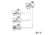
図15に示す例では、P&ID意味モデルM61、PFD意味モデルM62、及び機器リスト意味モデルM63を結合して結合意味モデルCM6を生成する例を図示している。これらの意味モデルを結合する場合には、例えば図15に示す通り、最初にP&ID意味モデルM61とPFD意味モデルM62とを結合する。そして、P&ID意味モデルM61とPFD意味モデルM62とを結合して得られる結合意味モデルと、機器リスト意味モデルM63とを結合して結合意味モデルCM6を生成する。 In the example shown in FIG. 15, an example in which the P & ID meaning model M61, the PFD meaning model M62, and the device list meaning model M63 are combined to generate the combined meaning model CM6 is shown. When combining these semantic models, for example, as shown in FIG. 15, the P & ID semantic model M61 and the PFD semantic model M62 are first combined. Then, the combined meaning model obtained by combining the P & ID meaning model M61 and the PFD meaning model M62 and the device list meaning model M63 are combined to generate the combined meaning model CM6.
尚、図15に示す結合順は、あくまでも一例であって、P&ID意味モデルM61、PFD意味モデルM62、及び機器リスト意味モデルM63を結合する場合の結合順が、図15に示す順に限定される訳ではない点に注意されたい。意味モデルの結合順は、例えば、意味モデルの種類、意味モデルの対象範囲等を考慮して任意に設定することが可能である。 The joining order shown in FIG. 15 is merely an example, and the joining order when the P & ID meaning model M61, the PFD meaning model M62, and the device list meaning model M63 are joined is limited to the order shown in FIG. Please note that it is not. The combination order of the semantic models can be arbitrarily set in consideration of, for example, the type of the semantic model, the target range of the semantic model, and the like.
図16は、本発明の一実施形態によるエンジニアリング支援システムの第2変形例を説明するための図である。上述した第1実施形態及び上述した第1変形例は、主に複数の意味モデルを結合して結合意味モデルを生成するものであった。本変形例は、既に生成されている結合意味モデルに意味モデルを結合させるものである。 FIG. 16 is a diagram for explaining a second modification of the engineering support system according to the embodiment of the present invention. In the above-described first embodiment and the above-mentioned first modification, a plurality of semantic models are mainly combined to generate a combined semantic model. In this modification, the semantic model is combined with the already generated combined semantic model.
図16に示す例では、P&ID意味モデルM71、PFD意味モデルM72、及び機器リスト意味モデルM73を、既に生成されている結合意味モデルCM7に結合させる例を図示している。これらの意味モデルを結合意味モデルCMに結合させる場合には、端末装置TMのユーザが、結合させる意味モデルを順に指定する。意味モデルを指定する順は、端末装置TMのユーザの任意である。尚、意味モデルの結合順は、第1変形例と同様に、例えば、意味モデルの種類、意味モデルの対象範囲等を考慮して任意に設定することが可能である。 In the example shown in FIG. 16, an example in which the P & ID meaning model M71, the PFD meaning model M72, and the device list meaning model M73 are combined with the already generated connection meaning model CM7 is shown. When these semantic models are combined with the combined semantic model CM, the user of the terminal device TM specifies the semantic models to be combined in order. The order in which the semantic model is specified is arbitrary for the user of the terminal device TM. As in the first modification, the combination order of the semantic models can be arbitrarily set in consideration of, for example, the type of the semantic model, the target range of the semantic model, and the like.
〈実装例〉
図17は、本発明の一実施形態によるエンジニアリング支援システムの第1実装例を示すブロック図である。図17に示す実装例は、1台のコンピュータにエンジニアリング支援システム1を実装した例である。図17に示す通り、エンジニアリング支援システム1が実装されるコンピュータ50は、操作部51、表示部52、入出力部53、演算部54、及び格納部55を備える。
<Implementation example>
FIG. 17 is a block diagram showing a first implementation example of the engineering support system according to the embodiment of the present invention. The mounting example shown in FIG. 17 is an example in which the
操作部51は、例えばキーボードやポインティングデバイス等の入力装置を備えており、エンジニアリング支援システム1を使用するユーザの操作に応じた指示(エンジニアリング支援システム1に対する指示)を演算部54に出力する。表示部52は、例えば液晶表示装置等の表示装置を備えており、演算部54から出力される各種情報を表示する。尚、操作部51及び表示部52は、物理的に分離されたものであっても良く、表示機能と操作機能とを兼ね備えるタッチパネル式の液晶表示装置のように物理的に一体化されたものであっても良い。
The
入出力部53は、演算部54の制御の下で、各種情報の入出力を行う。例えば、入出力部53は、外部の機器との間で通信を行って各種情報を入出力するものであっても良く、着脱可能な記録媒体(例えば、不揮発性メモリ)に対する各種情報の読み出し又は書き込みを行って各種情報を入出力するものであっても良い。尚、外部の機器との間で行われる通信は、有線通信及び無線通信の何れであっても良い。
The input /
演算部54は、操作部51からの指示に基づいて各種演算を行い、その演算結果を表示部52又は入出力部53に出力する。この演算部54には、エンジニアリング支援システム1の主要な構成である、変換部10、結合意味モデル管理部30、及びアプリケーション部40が設けられる。演算部54に設けられる機能は、その機能を実現するためのプログラムがCPU(中央処理装置)等のハードウェアによって実行されることによって実現される。つまり、変換部10、結合意味モデル管理部30、及びアプリケーション部40の機能は、ソフトウェアとハードウェア資源とが協働することによって実現される。
The
格納部55は、例えばHDD(ハードディスクドライブ)やSSD(ソリッドステートドライブ)等の補助記憶装置を備えており、各種情報を格納する。例えば、格納部55は、エンジニアリング支援システム1の主要な構成の一部である、意味モデルデータベース20を格納する。変換部10で変換された意味モデルや、結合意味モデル管理部30で生成された結合意味モデルが、意味モデルデータベース20に格納される。
The
図18は、本発明の一実施形態によるエンジニアリング支援システムの第2実装例を示すブロック図である。図18に示す実装例は、ネットワークNに接続された複数のサーバにてエンジニアリング支援システム1を実装した例である。図18に示す通り、エンジニアリング支援システム1は、変換サーバ61、意味モデルデータベースサーバ62、結合意味モデル管理サーバ63、及びアプリケーションサーバ64によって実装される。
FIG. 18 is a block diagram showing a second implementation example of the engineering support system according to the embodiment of the present invention. The implementation example shown in FIG. 18 is an example in which the
変換サーバ61は、変換部10を備えており、図面類を意味モデルに変換し、意味モデルを図面類に変換する機能を提供する。意味モデルデータベースサーバ62は、意味モデルデータベース20を備えており、意味モデルや結合意味モデルを格納する機能を提供する。結合意味モデル管理サーバ63は、結合意味モデル管理部30を備えており、意味モデルを結合して結合意味モデルを作成する機能、及び結合意味モデルから意味モデルを抽出する機能を提供する。アプリケーションサーバ64は、アプリケーション部40を備えており、エンジニアリング支援システム1が図面類FGの管理を行う上で有用な機能を提供する。尚、これらの機能の詳細は、既に説明したため、ここでの説明は省略する。
The
尚、図18では、エンジニアリング支援システム1が備える変換部10、意味モデルデータベース20、結合意味モデル管理部30、及びアプリケーション部40が、それぞれ個別のサーバに設けられる例を図示している。しかしながら、エンジニアリング支援システム1が備える変換部10、意味モデルデータベース20、結合意味モデル管理部30、及びアプリケーション部40のうちの2つ又は3つが、1つのサーバに設けられていても良い。例えば、意味モデルデータベース20及び結合意味モデル管理部30が1つのサーバに設けられるといった具合である。
Note that FIG. 18 illustrates an example in which the
以上説明した通り、本実施形態では、プロセス制御システムのエンジニアリングで用いられる図面類を、その図面類に含まれる要素を示す第1情報と要素同士の関係を示す第2情報とによって表現した意味モデルに変換し、複数の意味モデルの類似度に基づいて、複数の意味モデルを結合した結合意味モデルを生成するようにしている。このため、エンジニアリングに携わる複数のエンジニアが必要とする図面類を意味づけして集約することができる。 As described above, in the present embodiment, the drawings used in the engineering of the process control system are represented by the first information indicating the elements included in the drawings and the second information indicating the relationship between the elements. To generate a combined semantic model that combines multiple semantic models based on the similarity of multiple semantic models. Therefore, drawings required by a plurality of engineers involved in engineering can be meaningfully aggregated.
また、本実施形態によれば、結合意味モデルから、指示に応じた意味モデルを抽出し、抽出された意味モデルを図面類に変換するようにしている。これにより、エンジニアリングに携わるエンジニアが必要とする任意の図面類を得ることができる。 Further, according to the present embodiment, the semantic model according to the instruction is extracted from the combined semantic model, and the extracted semantic model is converted into drawings. As a result, it is possible to obtain arbitrary drawings required by engineers involved in engineering.
このように、本実施形態では、プロセス制御システムの実態が反映された図面類が、意味づけされて統合されている。これにより、エンジニアリングで使用される図面類が、エンジニアリングに携わるエンジニアの間で十分に共有されているといえることから、作業効率を大幅に改善することができる。 As described above, in the present embodiment, the drawings reflecting the actual state of the process control system are meaningfully integrated. As a result, it can be said that the drawings used in engineering are sufficiently shared among the engineers involved in engineering, so that the work efficiency can be greatly improved.
以上、本発明の一実施形態によるエンジニアリング支援システム及びエンジニアリング支援方法について説明したが、本発明は上記実施形態に制限される訳ではなく、本発明の範囲内で自由に変更が可能である。例えば、前述したエンジニアリング支援システム1の動作例(基本動作例及び第1〜第3応用動作例)では、理解を容易にするために、特定の図面類を例示して説明を行った。しかしながら、エンジニアリング支援システム1の各動作例で扱うことができる図面類は、例示した図面類に限られる訳ではなく、任意の図面類を扱うことが可能である。
Although the engineering support system and the engineering support method according to the embodiment of the present invention have been described above, the present invention is not limited to the above embodiment and can be freely changed within the scope of the present invention. For example, in the above-mentioned operation examples of the engineering support system 1 (basic operation examples and the first to third applied operation examples), specific drawings have been illustrated and described in order to facilitate understanding. However, the drawings that can be handled in each operation example of the
例えば、第2応用動作例では、A社のエンジニアリングツールで作成されたP&ID(図面類FG31)を、B社のエンジニアリングツールで利用可能なP&ID(図面類FG32)に変換する例について説明したが、P&ID以外の任意の図面類についても、P&IDと同様の変換が可能である。また、第2応用動作例において、A社のエンジニアリングツールで作成されたP&IDを、互換性が期待できるA社製シミュレータ用のシミュレーションモデルとして出力したり、或いは互換性が期待できないB社製シミュレータ用のシミュレーションモデルとして変換したりすることも可能である。 For example, in the second application operation example, an example of converting a P & ID (drawings FG31) created by the engineering tool of company A into a P & ID (drawings FG32) that can be used by the engineering tool of company B has been described. Any drawings other than P & ID can be converted in the same manner as P & ID. Further, in the second application operation example, the P & ID created by the engineering tool of the company A is output as a simulation model for the simulator of the company A, which can be expected to be compatible, or for the simulator of the company B, which cannot be expected to be compatible. It is also possible to convert it as a simulation model of.
また、エンジニアリング支援システム1は、クラウドコンピューティングにより実現されても良い。ここで、クラウドコンピューティングは、例えば、以下のURL(Uniform Resource Locator)で特定される文書に記載されている定義(米国国立標準技術研究所によって推奨される定義)に合致するものであっても良い。
http://nvlpubs.nist.gov/nistpubs/Legacy/SP/nistspecialpublication800-145.pdf
https://www.ipa.go.jp/files/000025366.pdf
Further, the
http://nvlpubs.nist.gov/nistpubs/Legacy/SP/nistspecialpublication800-145.pdf
https://www.ipa.go.jp/files/000025366.pdf
1 エンジニアリング支援システム
10 変換部
12 変換ルールデータベース
20 意味モデルデータベース
31 結合意味モデル生成部
32 マッチング部
33 マッチングルールデータベース
34 意味モデル情報抽出部
35 抽出ルールデータベース
40 アプリケーション部
CM 結合意味モデル
EM 抽出意味モデル
FG 図面類
M 意味モデル
1
Claims (12)
前記プロセス制御システムのエンジニアリングで用いられる図面類を、該図面類に含まれる要素を示す第1情報と要素同士の関係を示す第2情報とによって表現した意味モデルに変換する変換部と、
複数の前記意味モデルの類似度に基づいて、複数の前記意味モデルを結合した結合意味モデルを生成する結合意味モデル生成部と、
を備えるエンジニアリング支援システム。 An engineering support system that supports the engineering of process control systems.
A conversion unit that converts drawings used in the engineering of the process control system into a semantic model represented by first information indicating the elements included in the drawings and second information indicating the relationship between the elements.
A combined semantic model generator that generates a combined semantic model that combines a plurality of the semantic models based on the similarity of the plurality of the semantic models.
Engineering support system equipped with.
前記結合意味モデル生成部は、前記類似度算出部で算出された前記類似度に基づいて、前記結合意味モデルを生成する、
請求項1記載のエンジニアリング支援システム。 It is equipped with a similarity calculation unit that calculates the similarity.
The combination meaning model generation unit generates the combination meaning model based on the similarity calculated by the similarity calculation unit.
The engineering support system according to claim 1.
前記変換部は、前記意味モデル情報抽出部で抽出された前記抽出意味モデルを前記図面類に変換する、
請求項1から請求項4の何れか一項に記載のエンジニアリング支援システム。 It is provided with a semantic model information extraction unit that extracts an extraction semantic model according to an instruction from the combined semantic model.
The conversion unit converts the extracted semantic model extracted by the semantic model information extraction unit into the drawings.
The engineering support system according to any one of claims 1 to 4.
前記類似度算出部は、前記第1データベースに格納された前記算出規則に従って、複数の前記意味モデルについての前記類似度を算出する、
請求項2記載のエンジニアリング支援システム。 It is equipped with a first database that stores the calculation rules for similarity.
The similarity calculation unit calculates the similarity for a plurality of the semantic models according to the calculation rules stored in the first database.
The engineering support system according to claim 2.
前記変換部は、前記第2データベースに格納された前記変換規則に従って、前記図面類を前記意味モデルに変換し、前記意味モデルを前記図面類に変換する、
請求項5記載のエンジニアリング支援システム。 It is equipped with a second database that stores conversion rules between the drawings and the semantic model.
The conversion unit converts the drawings into the semantic model and converts the semantic model into the drawings according to the conversion rules stored in the second database.
The engineering support system according to claim 5.
前記意味モデル情報抽出部は、前記第3データベースに格納された前記抽出規則に従って、指示された範囲における指示された種類の前記図面類を作成するために必要な前記意味モデルを抽出する、
請求項5記載のエンジニアリング支援システム。 It is provided with a third database that stores extraction rules for extracting the semantic model from the combined semantic model.
The semantic model information extraction unit extracts the semantic model necessary for creating the drawings of the specified type in the specified range according to the extraction rule stored in the third database.
The engineering support system according to claim 5.
前記プロセス制御システムのエンジニアリングで用いられる図面類を、該図面類に含まれる要素を示す第1情報と要素同士の関係を示す第2情報とによって表現した意味モデルに変換する第1変換ステップと、
複数の前記意味モデルの類似度に基づいて、複数の前記意味モデルを結合した結合意味モデルを生成する結合意味モデル生成ステップと、
を有するエンジニアリング支援方法。 An engineering support method that supports the engineering of process control systems.
The first conversion step of converting the drawings used in the engineering of the process control system into a semantic model represented by the first information indicating the elements included in the drawings and the second information indicating the relationship between the elements.
A combined semantic model generation step that generates a combined semantic model that combines a plurality of the semantic models based on the similarity of the plurality of the semantic models.
Engineering support method with.
前記意味モデル情報抽出ステップで抽出された前記抽出意味モデルを前記図面類に変換する第2変換ステップと、
を有する請求項11記載のエンジニアリング支援方法。 A semantic model information extraction step for extracting an extraction semantic model according to an instruction from the combined semantic model, and
A second conversion step of converting the extracted semantic model extracted in the semantic model information extraction step into the drawings, and
11. The engineering support method according to claim 11.
Priority Applications (4)
| Application Number | Priority Date | Filing Date | Title |
|---|---|---|---|
| JP2018241195A JP6900946B2 (en) | 2018-12-25 | 2018-12-25 | Engineering support system and engineering support method |
| US16/724,810 US11467560B2 (en) | 2018-12-25 | 2019-12-23 | Engineering support system and engineering support method |
| EP19219436.3A EP3674957A1 (en) | 2018-12-25 | 2019-12-23 | Engineering support system and engineering support method |
| CN201911358947.9A CN111382173A (en) | 2018-12-25 | 2019-12-25 | Engineering support system and engineering support method |
Applications Claiming Priority (1)
| Application Number | Priority Date | Filing Date | Title |
|---|---|---|---|
| JP2018241195A JP6900946B2 (en) | 2018-12-25 | 2018-12-25 | Engineering support system and engineering support method |
Publications (2)
| Publication Number | Publication Date |
|---|---|
| JP2020102115A JP2020102115A (en) | 2020-07-02 |
| JP6900946B2 true JP6900946B2 (en) | 2021-07-14 |
Family
ID=69005628
Family Applications (1)
| Application Number | Title | Priority Date | Filing Date |
|---|---|---|---|
| JP2018241195A Active JP6900946B2 (en) | 2018-12-25 | 2018-12-25 | Engineering support system and engineering support method |
Country Status (4)
| Country | Link |
|---|---|
| US (1) | US11467560B2 (en) |
| EP (1) | EP3674957A1 (en) |
| JP (1) | JP6900946B2 (en) |
| CN (1) | CN111382173A (en) |
Families Citing this family (2)
| Publication number | Priority date | Publication date | Assignee | Title |
|---|---|---|---|---|
| KR102046147B1 (en) * | 2018-12-28 | 2019-11-18 | 플랜트에셋 주식회사 | The consistency examination method of engineering data of 3D CAD model for plant engineering |
| WO2023073466A1 (en) * | 2021-10-25 | 2023-05-04 | Yokogawa Electric Corporation | Automated design of process automation facilities |
Family Cites Families (14)
| Publication number | Priority date | Publication date | Assignee | Title |
|---|---|---|---|---|
| JP2859407B2 (en) | 1990-09-27 | 1999-02-17 | 株式会社東芝 | Maintenance management system |
| JP3445470B2 (en) | 1997-07-09 | 2003-09-08 | 株式会社東芝 | Maintenance information management support apparatus and method |
| AUPQ246899A0 (en) * | 1999-08-26 | 1999-09-16 | Memetrics | An automated communications management agent |
| JP2007536634A (en) * | 2004-05-04 | 2007-12-13 | フィッシャー−ローズマウント・システムズ・インコーポレーテッド | Service-oriented architecture for process control systems |
| US7583272B2 (en) * | 2004-11-29 | 2009-09-01 | Purdue Research Foundation | Methods for retrieving shapes and drawings |
| CN1955991A (en) * | 2005-10-25 | 2007-05-02 | 国际商业机器公司 | Method and device for integrating model sementics and field sementics in service model |
| CN101354759A (en) * | 2007-07-23 | 2009-01-28 | 兰雨晴 | Method and system of work process flow defining conversion based on element model |
| US20120109901A1 (en) * | 2009-07-01 | 2012-05-03 | Nec Corporation | Content classification apparatus, content classification method, and content classification program |
| US20110218777A1 (en) * | 2010-03-03 | 2011-09-08 | Honeywell International Inc. | System and method for generating a building information model |
| EP2628071A4 (en) * | 2010-10-15 | 2016-05-18 | Qliktech Internat Ab | Method and system for developing data integration applications with reusable semantic types to represent and process application data |
| EP3029535A3 (en) | 2014-12-03 | 2016-07-13 | Rockwell Automation Technologies, Inc. | P&ID and control system synchronization |
| US10248626B1 (en) * | 2016-09-29 | 2019-04-02 | EMC IP Holding Company LLC | Method and system for document similarity analysis based on common denominator similarity |
| US11093856B2 (en) | 2017-02-28 | 2021-08-17 | Accenture Global Solutions Limited | Interpretation of predictive models using semantic grouping |
| CN107704453B (en) * | 2017-10-23 | 2021-10-08 | 深圳市前海众兴科研有限公司 | Character semantic analysis method, character semantic analysis terminal and storage medium |
-
2018
- 2018-12-25 JP JP2018241195A patent/JP6900946B2/en active Active
-
2019
- 2019-12-23 EP EP19219436.3A patent/EP3674957A1/en not_active Ceased
- 2019-12-23 US US16/724,810 patent/US11467560B2/en active Active
- 2019-12-25 CN CN201911358947.9A patent/CN111382173A/en active Pending
Also Published As
| Publication number | Publication date |
|---|---|
| US11467560B2 (en) | 2022-10-11 |
| CN111382173A (en) | 2020-07-07 |
| US20200201285A1 (en) | 2020-06-25 |
| JP2020102115A (en) | 2020-07-02 |
| EP3674957A1 (en) | 2020-07-01 |
Similar Documents
| Publication | Publication Date | Title |
|---|---|---|
| CN108351636B (en) | Engineering design tool, system and module | |
| US7600234B2 (en) | Method for launching applications | |
| JP2006516057A5 (en) | ||
| JP6624008B2 (en) | Engineering tool cooperation device, engineering tool cooperation method, engineering tool cooperation program and recording medium | |
| JP6961156B2 (en) | Methods and systems for modeling the behavior of physical plants | |
| CN104281119B (en) | Support the method and system of the technical assignment in dcs | |
| JP6900946B2 (en) | Engineering support system and engineering support method | |
| JP6540787B1 (en) | Device, method, and program | |
| WO2015131916A1 (en) | Optimized method for sorting alarms | |
| JP2019121113A (en) | Device, method and program | |
| JP2014035687A (en) | Engineering system and monitoring control method thereof | |
| JP2016133879A (en) | Engineering support device, method and program | |
| EP3223090A1 (en) | Supervisory control and data acquisition system and data engineering method thereof | |
| WO2013085913A2 (en) | Computer method and apparatus converting process engineering application data into a canonical flowsheet representation | |
| Van Hoecke et al. | Dynamic monitoring dashboards through composition of Web and visualization services | |
| Neges et al. | Enabling round-trip engineering between P&I diagrams and augmented reality work instructions in maintenance processes utilizing graph-based modelling | |
| JP6139389B2 (en) | Plant control logic design support system, plant control logic design support method, and program | |
| JP5489781B2 (en) | Supervisory control system | |
| JP2009266141A (en) | Data processor and data processing method | |
| JP5225755B2 (en) | Data processing apparatus and data processing method | |
| US20190130055A1 (en) | Manifold generator | |
| JP2003262696A (en) | Engineering tool for nuclear power plant | |
| JPH08278808A (en) | Simulation device | |
| JP2013225188A (en) | Training system for decentralized control system and training control state setting method |
Legal Events
| Date | Code | Title | Description |
|---|---|---|---|
| A621 | Written request for application examination |
Free format text: JAPANESE INTERMEDIATE CODE: A621 Effective date: 20200318 |
|
| A977 | Report on retrieval |
Free format text: JAPANESE INTERMEDIATE CODE: A971007 Effective date: 20210428 |
|
| TRDD | Decision of grant or rejection written | ||
| A01 | Written decision to grant a patent or to grant a registration (utility model) |
Free format text: JAPANESE INTERMEDIATE CODE: A01 Effective date: 20210518 |
|
| A61 | First payment of annual fees (during grant procedure) |
Free format text: JAPANESE INTERMEDIATE CODE: A61 Effective date: 20210531 |
|
| R150 | Certificate of patent or registration of utility model |
Ref document number: 6900946 Country of ref document: JP Free format text: JAPANESE INTERMEDIATE CODE: R150 |