JP6900372B2 - Nebulizer and container - Google Patents
Nebulizer and container Download PDFInfo
- Publication number
- JP6900372B2 JP6900372B2 JP2018523431A JP2018523431A JP6900372B2 JP 6900372 B2 JP6900372 B2 JP 6900372B2 JP 2018523431 A JP2018523431 A JP 2018523431A JP 2018523431 A JP2018523431 A JP 2018523431A JP 6900372 B2 JP6900372 B2 JP 6900372B2
- Authority
- JP
- Japan
- Prior art keywords
- container
- nebulizer
- control
- display device
- control member
- Prior art date
- Legal status (The legal status is an assumption and is not a legal conclusion. Google has not performed a legal analysis and makes no representation as to the accuracy of the status listed.)
- Active
Links
Images


Classifications
-
- A—HUMAN NECESSITIES
- A61—MEDICAL OR VETERINARY SCIENCE; HYGIENE
- A61M—DEVICES FOR INTRODUCING MEDIA INTO, OR ONTO, THE BODY; DEVICES FOR TRANSDUCING BODY MEDIA OR FOR TAKING MEDIA FROM THE BODY; DEVICES FOR PRODUCING OR ENDING SLEEP OR STUPOR
- A61M15/00—Inhalators
- A61M15/0065—Inhalators with dosage or measuring devices
- A61M15/0068—Indicating or counting the number of dispensed doses or of remaining doses
- A61M15/0081—Locking means
-
- A—HUMAN NECESSITIES
- A61—MEDICAL OR VETERINARY SCIENCE; HYGIENE
- A61M—DEVICES FOR INTRODUCING MEDIA INTO, OR ONTO, THE BODY; DEVICES FOR TRANSDUCING BODY MEDIA OR FOR TAKING MEDIA FROM THE BODY; DEVICES FOR PRODUCING OR ENDING SLEEP OR STUPOR
- A61M11/00—Sprayers or atomisers specially adapted for therapeutic purposes
- A61M11/006—Sprayers or atomisers specially adapted for therapeutic purposes operated by applying mechanical pressure to the liquid to be sprayed or atomised
- A61M11/007—Syringe-type or piston-type sprayers or atomisers
-
- A—HUMAN NECESSITIES
- A61—MEDICAL OR VETERINARY SCIENCE; HYGIENE
- A61M—DEVICES FOR INTRODUCING MEDIA INTO, OR ONTO, THE BODY; DEVICES FOR TRANSDUCING BODY MEDIA OR FOR TAKING MEDIA FROM THE BODY; DEVICES FOR PRODUCING OR ENDING SLEEP OR STUPOR
- A61M15/00—Inhalators
- A61M15/0065—Inhalators with dosage or measuring devices
- A61M15/0068—Indicating or counting the number of dispensed doses or of remaining doses
- A61M15/007—Mechanical counters
- A61M15/0071—Mechanical counters having a display or indicator
-
- A—HUMAN NECESSITIES
- A61—MEDICAL OR VETERINARY SCIENCE; HYGIENE
- A61M—DEVICES FOR INTRODUCING MEDIA INTO, OR ONTO, THE BODY; DEVICES FOR TRANSDUCING BODY MEDIA OR FOR TAKING MEDIA FROM THE BODY; DEVICES FOR PRODUCING OR ENDING SLEEP OR STUPOR
- A61M15/00—Inhalators
- A61M15/0001—Details of inhalators; Constructional features thereof
- A61M15/0021—Mouthpieces therefor
- A61M15/0025—Mouthpieces therefor with caps
- A61M15/0026—Hinged caps
-
- A—HUMAN NECESSITIES
- A61—MEDICAL OR VETERINARY SCIENCE; HYGIENE
- A61M—DEVICES FOR INTRODUCING MEDIA INTO, OR ONTO, THE BODY; DEVICES FOR TRANSDUCING BODY MEDIA OR FOR TAKING MEDIA FROM THE BODY; DEVICES FOR PRODUCING OR ENDING SLEEP OR STUPOR
- A61M2202/00—Special media to be introduced, removed or treated
- A61M2202/0007—Special media to be introduced, removed or treated introduced into the body
-
- A—HUMAN NECESSITIES
- A61—MEDICAL OR VETERINARY SCIENCE; HYGIENE
- A61M—DEVICES FOR INTRODUCING MEDIA INTO, OR ONTO, THE BODY; DEVICES FOR TRANSDUCING BODY MEDIA OR FOR TAKING MEDIA FROM THE BODY; DEVICES FOR PRODUCING OR ENDING SLEEP OR STUPOR
- A61M2202/00—Special media to be introduced, removed or treated
- A61M2202/04—Liquids
- A61M2202/0468—Liquids non-physiological
-
- A—HUMAN NECESSITIES
- A61—MEDICAL OR VETERINARY SCIENCE; HYGIENE
- A61M—DEVICES FOR INTRODUCING MEDIA INTO, OR ONTO, THE BODY; DEVICES FOR TRANSDUCING BODY MEDIA OR FOR TAKING MEDIA FROM THE BODY; DEVICES FOR PRODUCING OR ENDING SLEEP OR STUPOR
- A61M2202/00—Special media to be introduced, removed or treated
- A61M2202/06—Solids
- A61M2202/064—Powder
-
- A—HUMAN NECESSITIES
- A61—MEDICAL OR VETERINARY SCIENCE; HYGIENE
- A61M—DEVICES FOR INTRODUCING MEDIA INTO, OR ONTO, THE BODY; DEVICES FOR TRANSDUCING BODY MEDIA OR FOR TAKING MEDIA FROM THE BODY; DEVICES FOR PRODUCING OR ENDING SLEEP OR STUPOR
- A61M2205/00—General characteristics of the apparatus
- A61M2205/27—General characteristics of the apparatus preventing use
- A61M2205/273—General characteristics of the apparatus preventing use preventing reuse, e.g. of disposables
-
- B—PERFORMING OPERATIONS; TRANSPORTING
- B05—SPRAYING OR ATOMISING IN GENERAL; APPLYING FLUENT MATERIALS TO SURFACES, IN GENERAL
- B05B—SPRAYING APPARATUS; ATOMISING APPARATUS; NOZZLES
- B05B11/00—Single-unit hand-held apparatus in which flow of contents is produced by the muscular force of the operator at the moment of use
- B05B11/0005—Components or details
- B05B11/0037—Containers
- B05B11/0054—Cartridges, i.e. containers specially designed for easy attachment to or easy removal from the rest of the sprayer
-
- B—PERFORMING OPERATIONS; TRANSPORTING
- B05—SPRAYING OR ATOMISING IN GENERAL; APPLYING FLUENT MATERIALS TO SURFACES, IN GENERAL
- B05B—SPRAYING APPARATUS; ATOMISING APPARATUS; NOZZLES
- B05B11/00—Single-unit hand-held apparatus in which flow of contents is produced by the muscular force of the operator at the moment of use
- B05B11/01—Single-unit hand-held apparatus in which flow of contents is produced by the muscular force of the operator at the moment of use characterised by the means producing the flow
- B05B11/10—Pump arrangements for transferring the contents from the container to a pump chamber by a sucking effect and forcing the contents out through the dispensing nozzle
- B05B11/109—Pump arrangements for transferring the contents from the container to a pump chamber by a sucking effect and forcing the contents out through the dispensing nozzle the dispensing stroke being affected by the stored energy of a spring
- B05B11/1091—Pump arrangements for transferring the contents from the container to a pump chamber by a sucking effect and forcing the contents out through the dispensing nozzle the dispensing stroke being affected by the stored energy of a spring being first hold in a loaded state by locking means or the like, then released
Description
本発明は、請求項1の前段部に記載のネブライザ、及び請求項13の前段部に記載の容器に関する。
The present invention relates to the nebulizer according to the preceding portion of
WO 2012/162305 A1は、ネブライザを開示している。容器は、ネブライザのハウジングの中に挿入することができる。ハウジングは、下側ハウジング部分によって閉じられる。ハウジング部分を回転させることにより、駆動バネを引張下に置くことができ、流体を圧力発生器の圧縮チャンバ内に吸い込むことができる。同時に、容器は、ネブライザ内の行程移動で下側ハウジング部分内に移動される。ボタンを手動で押圧した後に、駆動バネは、流体が駆動バネによって加圧下に置かれ、かつ推進剤ガスを使用せずにエアロゾルとしてノズルを通してマウスピースの中に送出又は噴霧されるように、解除されて送出チューブを圧力チャンバの中に移動する。すなわち、容器は、噴霧される流体の搬送中及び圧力発生及び噴霧中に前後に軸線方向に移動している。ネブライザは、実施されたか又は依然として実施可能な使用回数を計数し、及び/又は示すための表示デバイスを含む。表示デバイスは、予め決められた使用回数が現在の容器によって到達されるか又は超過された時にロック状態で更なる使用を阻止する。次に、容器は、ハウジング部分と共に取り替えることができ、ネブライザは、新しい容器と共に更に使用することができる。 WO 2012/162305 A1 discloses a nebulizer. The container can be inserted into the nebulizer housing. The housing is closed by the lower housing portion. By rotating the housing portion, the drive spring can be placed under tension and the fluid can be drawn into the compression chamber of the pressure generator. At the same time, the container is moved into the lower housing portion by stroke movement within the nebulizer. After manually pressing the button, the drive spring is released so that the fluid is placed under pressure by the drive spring and is delivered or sprayed into the mouthpiece through the nozzle as an aerosol without the use of propellant gas. The delivery tube is moved into the pressure chamber. That is, the container moves in the axial direction back and forth during transport of the fluid to be sprayed and during pressure generation and spraying. The nebulizer includes a display device for counting and / or indicating the number of uses that have been or are still feasible. The display device locks to prevent further use when a predetermined number of uses is reached or exceeded by the current container. The container can then be replaced with the housing portion and the nebulizer can be further used with a new container.
WO 2007/022898 A2は、ハウジング部分から分離不能である容器と共に交換可能又は取替可能であるハウジング部分に計数デバイスを一体化することができる類似のネブライザを開示している。 WO 2007/022898 A2 discloses a similar nebulizer that allows the counting device to be integrated into a replaceable or replaceable housing portion with a container that is inseparable from the housing portion.
本発明の目的は、簡単及び/又はセキュアな作動及び取り扱い、及び/又は小型及び/又は信頼できる構成を可能にするネブライザ及びネブライザのための容器を、好ましくはネブライザのいずれのハウジング部分の取替もなしに容器の取替を可能にしながら、好ましくは既に使用した容器の再使用又は再挿入を防止しながら、提供することである。 An object of the present invention is to replace a nebulizer and a container for the nebulizer, preferably any housing portion of the nebulizer, which allows for easy and / or secure operation and handling, and / or small and / or reliable configuration. It is to be provided while allowing the replacement of the container without any fuss, preferably while preventing the reuse or reinsertion of the already used container.
上記目的は、請求項1に記載のネブライザ、又は請求項13に記載の容器によって達成される。好ましい実施形態は、従属請求項の主題である。
The above object is achieved by the nebulizer according to
本発明は、流体、好ましくは液体薬剤をその流体を収容する取替可能な容器から噴霧するためのネブライザに関し、かつその容器に関する。 The present invention relates to and relates to a nebulizer for spraying a fluid, preferably a liquid drug, from a replaceable container containing the fluid.
ネブライザは、通常の又は予め定められた使用の後に、特に、容器を備えたネブライザの使用回数が予め決められた使用回数に到達したか又は超過した後にロック状態での容器を備えたネブライザの更なる使用を阻止するための及び/又は容器なしの引渡状態でのネブライザの使用を阻止するためのロッキングデバイスを含む。用語「ネブライザの使用」は、特に、ネブライザが阻止されていない時にネブライザによる、好ましくは計量された投薬量の流体の噴霧のために又はエアロゾルの発生のために必要である作動段階を実行することを指す。そのような作動段階は、典型的には、充填する(例えば、流体の投与量を計量する)、装填する(例えば、エネルギ貯蔵を装填する)、及び/又は噴霧又はエアロゾルをトリガ/起動/解放する段階を含む。用語「引渡状態」は、例えば、ネブライザが、それが製造場所を離れる時に又はそれがユーザ又は患者に配布される前に、出荷されるか又は出荷することができる状態を指す。 A nebulizer is a refurbishment of a nebulizer with a container in a locked state after normal or predetermined use, in particular after the number of uses of the nebulizer with a container reaches or exceeds a predetermined number of uses. Includes a locking device to prevent the use of the nebulizer and / or to prevent the use of the nebulizer in the undelivered state. The term "use of a nebulizer" refers to performing the steps necessary for the nebulizer to spray a fluid, preferably in a metered dosage, or for the generation of an aerosol, especially when the nebulizer is not blocked. Point to. Such operating steps typically fill (eg, weigh the dose of fluid), load (eg, load energy storage), and / or trigger / activate / release the spray or aerosol. Including the stage to do. The term "delivery state" refers to, for example, a state in which a nebulizer can be shipped or shipped when it leaves the place of manufacture or before it is distributed to a user or patient.
本発明により、容器は、容器の未使用状態を示し(最初に)、かつロッキングデバイスをアンロックすることによってネブライザを阻止解除するための制御デバイスを含む。これは、使用された容器を未使用容器に取り替えることによってネブライザの非常に簡単な実現及びリセットを可能にする。 According to the present invention, the container includes a control device for indicating the unused state of the container (first) and for deterring and releasing the nebulizer by unlocking the locking device. This allows for a very easy implementation and reset of the nebulizer by replacing the used container with an unused container.
本発明の代替又は追加の態様により、容器は、容器の使用された状態を示してネブライザの阻止解除又はロッキングデバイスのアンロックを回避するための制御デバイスを含む。すなわち、既に使用した容器の再使用又は再挿入を防止することができる。 According to an alternative or additional aspect of the invention, the container comprises a control device for indicating the used state of the container to avoid deblocking the nebulizer or unlocking the locking device. That is, it is possible to prevent the reuse or reinsertion of the already used container.
好ましくは、容器によって既に実行されたか又は依然として実施可能な使用回数を計数する及び/又は示すための表示デバイスが提供される。 Preferably, a display device is provided for counting and / or indicating the number of uses already performed or still feasible by the container.
好ましくは、ネブライザは、容器を挿入又は取り替えるために開かれる又はネブライザから取り外すことができるハウジング部分を含む。特に、表示デバイスは、このハウジング部分に配置されるか又はそこから分離不能である。 Preferably, the nebulizer includes a housing portion that can be opened or removed from the nebulizer to insert or replace the container. In particular, the display device is located in or inseparable from this housing portion.
特に、表示デバイス又は関連のロッキングデバイスは、ネブライザを阻止することができ、又は予め決められた使用回数がそれぞれの容器によって到達されるか又は超過された時にロック状態での更なる使用に対してネブライザの阻止を引き起こすことができる。 In particular, the display device or associated locking device can thwart the nebulizer, or for further use in the locked state when a predetermined number of uses is reached or exceeded by each container. Can cause nebulizer blockage.
特に、制御デバイスは、特に容器がネブライザと共に最初に使用される時にネブライザの表示デバイス又はロッキングデバイスを起動又はリセットするためのものである。 In particular, the control device is for activating or resetting the nebulizer's display or locking device, especially when the container is first used with the nebulizer.
好ましくは、制御デバイスは、ロッキングデバイスを間接的に、特に表示デバイスを通じて、アンロック、起動、又は制御する。 Preferably, the control device unlocks, activates, or controls the locking device indirectly, especially through the display device.
好ましくは、制御デバイスは、未使用容器がネブライザと共に最初に使用される及び/又はネブライザに最初に挿入される時に、表示デバイスをリセットする及び/又はネブライザのロック状態をリセットする。 Preferably, the control device resets the display device and / or resets the nebulizer's locked state when the unused container is first used with the nebulizer and / or is first inserted into the nebulizer.
好ましくは、ネブライザ1は、容器3が接続又は挿入されることなくロック状態で引き渡される。すなわち、ネブライザ1は、特にロッキングデバイスによってその引渡状態での使用に対して阻止される。この第1のロック状態は、好ましくは、未使用容器を単に接続又は挿入すること、特にネブライザを(完全に)閉じることによってのみ打ち勝つことができる。すなわち、制御デバイスは、ネブライザが最初に未使用容器と共に使用される時に表示デバイスを最初にリセットする。
Preferably, the
好ましくは、表示デバイスは、ロッキングデバイスを制御又は起動する。好ましくは、表示デバイス、特に表示デバイスの回転可能な部分は、ロッキングデバイスと協働する及び/又はその制御要素に当接する少なくとも1つの突起及び/又は凹部を含む。特に、突起が制御要素又は凹部から離れて制御要素と接触するように移動する時に、制御要素は、(特に付勢力に起因して)好ましくは軸線方向に移動する。制御要素のこの好ましくは軸線方向の移動は、ロック位置内に又はロック位置から外にボルト又はロッキング要素を移動する。 Preferably, the display device controls or activates the locking device. Preferably, the display device, in particular the rotatable portion of the display device, comprises at least one protrusion and / or recess that cooperates with the locking device and / or abuts its control element. In particular, when the protrusion moves away from the control element or recess so as to come into contact with the control element, the control element preferably moves in the axial direction (particularly due to urging forces). This preferably axial movement of the control element moves the bolt or locking element into or out of the lock position.
好ましくは、ネブライザは、容器を取り替えるためにネブライザから取り外すか又は開くことができるハウジング部分を含む。 Preferably, the nebulizer includes a housing portion that can be removed or opened from the nebulizer to replace the container.
好ましくは、表示デバイスは、ハウジング部分に配置される。 Preferably, the display device is located in the housing portion.
好ましくは、ロッキングデバイスは、ロック状態でネブライザの引張を阻止するようになっている。 Preferably, the locking device is adapted to prevent the nebulizer from being pulled in the locked state.
更なる使用に対するネブライザの阻止は、(使用された)容器をまだ使用されていないものと取り替えることによって打ち勝つことができる。 Nebulizer blocking against further use can be overcome by replacing the (used) container with one that has not yet been used.
好ましくは、制御デバイスは、容器と、又は容器の容器ハウジングと分離不能に接続されるが、制御デバイスが容器と共に取替可能であるようにネブライザ又はそのハウジングから、そしてハウジング部分から分離可能である。これは、ネブライザ及び好ましくは表示デバイスを含むハウジング部分の、別の制御デバイスを含む別の容器との再使用を可能にする。すなわち、交換される構成要素の全体サイズは、取替パッケージのサイズを縮小して多数のパッケージの輸送が容易になるように、小さく保たれる。 Preferably, the control device is inseparably connected to the container or to the container housing of the container, but is separable from the nebulizer or its housing and from the housing portion such that the control device is replaceable with the container. .. This allows reuse of the housing portion containing the nebulizer and preferably the display device with another container containing another control device. That is, the overall size of the components to be replaced is kept small so that the size of the replacement package can be reduced to facilitate the transportation of a large number of packages.
好ましくは、制御デバイスは、容器の底部に及び/又は容器の出口の反対側に固定的に配置される。これは、非常に小型の構成を可能にする。更に、制御デバイスは、ネブライザへの容器の流体的接続に干渉せず、又はその逆も同じである。 Preferably, the control device is fixedly located at the bottom of the container and / or opposite the outlet of the container. This allows for very small configurations. Moreover, the control device does not interfere with the fluid connection of the container to the nebulizer and vice versa.
特に、制御デバイスは、好ましくは移動可能であり、特に押下可能及び/又は軸線方向移動可能である制御部材を含む。 In particular, the control device preferably includes a control member that is movable, particularly pushable and / or axially movable.
好ましくは、制御部材は、特に第1の位置で関連の容器の最初の未使用状態を示し、かつ、特に第2の位置で関連の容器の既に使用した状態を示すために、最初の使用又はネブライザの中への挿入の前と後で異なる位置に保持される。 Preferably, the control member is initially used or to indicate the initial unused state of the relevant container, especially in the first position, and particularly in the second position to indicate the already used state of the relevant container. It is held in different positions before and after insertion into the nebulizer.
用語「使用された」又は「使用された状態」は、特に容器に関して、流体の少なくとも1回の投与量が既に容器から抽出又は引き出されていること、又は容器がネブライザによって流体の少なくとも1回の投与量を、特に予め決められた使用回数まで、既に放出していること、又は容器が、特にネブライザのハウジングが完全に閉じた状態で、ネブライザの中に挿入されていること、又は容器が少なくとも一度ネブライザと(流体的及び/又は機械的に)接続されていることを意味する。 The term "used" or "used state" means that at least one dose of fluid has already been extracted or withdrawn from the container, especially with respect to the container, or that the container is at least once in fluid by a nebulizer. The dose has already been released, especially up to a predetermined number of uses, or the container has been inserted into the nebulizer, especially with the nebulizer housing fully closed, or the container has at least It means that it is once (fluidally and / or mechanically) connected to the nebulizer.
用語「未使用」又は「未使用状態」は、特に容器に関して、容器が流体の少なくとも1回の投与量を放出するのに使用されていないこと、及び/又は容器が、特にネブライザのハウジングが完全に閉じた状態で、ネブライザの中に挿入されていないこと、及び/又は容器が少なくとも一度もネブライザと(流体的及び/又は機械的に)接続されていないことを意味する。 The term "unused" or "unused" means that the container has not been used to release at least one dose of fluid, especially with respect to the container, and / or the container, especially the nebulizer housing, is complete. It means that it has not been inserted into the nebulizer and / or the container has never been (fluidally and / or mechanically) connected to the nebulizer in the closed state.
これに加えて、制御部材は、第1及び第2の位置間で中間位置又は状態を取ることができる。好ましくは、中間状態は、制御デバイス又は制御部材が、使用された状態を示すこと、及び/又はそれぞれの容器がネブライザの中に(再度)挿入されるか又はそれに接続される時にネブライザの阻止解除に適さないか又はそれを防止することをもたらす場合がある。この中間状態において、いずれの流体も容器から放出されておらず、特に、容器とのいずれの引張も起こっていないが、容器は「使用されている」と考えることができる。 In addition to this, the control member can take an intermediate position or state between the first and second positions. Preferably, the intermediate state indicates that the control device or control member has been used and / or the nebulizer is unblocked when each container is (re) inserted into or connected to the nebulizer. May result in being unsuitable for or preventing it. In this intermediate state, no fluid has been released from the container, and in particular no tension with the container has occurred, but the container can be considered "used".
好ましくは、制御デバイス又は制御部材は、既に使用した容器がネブライザの中に再挿入されるか又はそれと再接続される場合に、特に制御部材又はデバイスが阻止解除するのに必要なその初期位置又は第1の位置にないので、ネブライザ又はロッキングデバイスを阻止解除(アンロック)しない。 Preferably, the control device or control member is in its initial position or required for the control member or device to unblock, especially when the already used container is reinserted into or reconnected to the nebulizer. Since it is not in the first position, it does not unlock the nebulizer or locking device.
好ましくは、ロック状態は、使用された容器がネブライザの中に挿入されるか又はそれに接続される時に、好ましくはネブライザを完全に閉じる時に、制御デバイス又はその制御部材によって自動で再開されるか又はリセットされる。 Preferably, the locked state is automatically resumed by the control device or its control members when the used container is inserted into or connected to the nebulizer, preferably when the nebulizer is completely closed. It will be reset.
好ましくは、表示デバイスは、未使用容器がネブライザの中に挿入されるか又はネブライザに接続される時に、好ましくはネブライザを完全に閉じる時に、自動でリセットされる。 Preferably, the display device is automatically reset when the unused container is inserted into or connected to the nebulizer, preferably when the nebulizer is completely closed.
好ましくは、表示デバイスは、表示要素を回転送りするための少なくとも1つの表示要素及び起動要素を含む。特に、表示要素は、それぞれの容器によって既に実行されたか又は依然として実施可能な使用回数を表示する。 Preferably, the display device includes at least one display element and an activation element for rotating the display element. In particular, the display element displays the number of uses that have already been performed or are still feasible by each container.
好ましくは、起動要素の直線又は軸線方向移動は、表示要素の回転移動を引き起こす。 Preferably, the linear or axial movement of the activation element causes a rotational movement of the display element.
更により好ましくは、起動要素は、表示デバイスを有する容器とネブライザのハウジング及び/又はハウジング部分との間の長手方向相対移動によって動かされる。 Even more preferably, the activation element is driven by longitudinal relative movement between the container with the display device and the housing and / or housing portion of the nebulizer.
本発明の上記態様及び以下に説明する追加の態様は、互いに独立にかつあらゆる組合せに実現することができる。 The above aspects of the invention and the additional aspects described below can be realized independently of each other and in any combination.
本発明の更に別の利点、特徴、特性、及び態様は、特許請求の範囲及び図面を参照する好ましい実施形態の以下の説明から明らかになるであろう。 Yet another advantage, feature, property, and aspect of the invention will become apparent from the following description of preferred embodiments with reference to the claims and drawings.
図において、同じ参照番号は、同一又は類似の部品に使用され、好ましくは、関連の説明を繰り返さない場合でも対応するか又は同等の特性及び利点をもたらす。 In the figure, the same reference numbers are used for the same or similar parts and preferably provide corresponding or equivalent properties and advantages without repeating the relevant description.
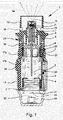
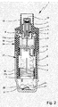
図1及び2は、流体2、特に、非常に有効な医薬組成物又は薬剤などを噴霧するための公知のネブライザ1を非引張状態(図1)及び引張状態(図2)で図式的に示している。ネブライザ1は、特に携帯用吸入器として構成され、好ましくは、機械的にのみ及び/又は推進剤ガスなしで作動する。
1 and 2 schematically show a
流体2、好ましくは、液体、特に、医薬組成物を噴霧する時に、エアロゾル14(図1)が形成又は小出しされ、これをユーザが吸い込み又は吸入することができる。一般的に、患者が罹っている症状又は病気に応じて少なくとも1日1回、特に、1日数回、好ましくは、設定された間隔で吸入を行う。
When spraying a
ネブライザ1には、流体2を収容する挿入可能又は取替可能な容器3が備えられるか又はそれを含む。従って、容器3は、噴霧される流体2のためのリザーバを形成する。好ましくは、容器3は、200までの投薬単位又は投薬量を提供し、例えば、すなわち、200までの噴霧又は適用を可能にするのに特に十分な複数の投薬量の流体2又は活性物質を収容する。WO 96/06011 A1において開示するような典型的な容器3は、例えば、約2〜20mlの容積を保持する。
The
更に、容器3に収容される投与数及び/又は容器3に収容される流体2の全容積は、流体2又はそれぞれの薬剤に応じて及び/又は容器3に応じて及び/又は必要な薬物療法などに応じて異なる場合がある。
Further, the number of doses contained in the container 3 and / or the total volume of the
好ましくは、容器3は、取り替える又は交換することができ、ネブライザ1の全使用回数及び従って同じネブライザ1と共に使用することができる容器3の数は、例えば、容器3について合計4個、5個、又は6個に制限することが好ましい。WO 2012/162305 A1は、更に、同じネブライザ1と共に使用することができる容器3の総数をそのように制限することを開示している。
Preferably, the container 3 can be replaced or replaced, and the total number of uses of the
容器3は、好ましくは、実質的に円筒形又はカートリッジ形であり、ネブライザ1が開かれた状態で、容器3は、好ましくは、下からその中に挿入され、必要に応じて交換することができる。それは、剛性構造であることが好ましく、特に流体2は、容器3内の圧潰バッグ4に保持されている。特に、容器3は、最初に使用する前又は最初の使用中に開いている通気開口部又は孔23を含む。
The container 3 is preferably substantially cylindrical or cartridge-shaped, and with the
ネブライザ1は、送出機構、好ましくは、特に事前設定されたかつ任意的に調節可能な投与量の流体2を搬送及び噴霧するための圧力発生器5を含む。
The
ネブライザ1又は圧力発生器5は、好ましくは、容器3を解除可能に保持するためのホルダ6、単に部分的に示すホルダ6に関連付けられた駆動バネ7、及び/又は好ましくは手動起動又は押下のためのボタンの形態の又はそれを有する阻止要素8を含む。阻止要素8は、ホルダ6を捕捉して阻止(ブロック)することができ、かつ手動で作動されてホルダ6を解除して駆動バネ7を拡張することを可能にすることができる。
The
ネブライザ1又は圧力発生器5は、好ましくは、搬送チューブ9のような搬送要素、逆止弁10、マウスピース13の中に流体2を噴霧するための圧力チャンバ11及び/又はノズル12を含む。
The
完全に挿入された容器3は、搬送要素が容器3をネブライザ1又は圧力発生器5に流体的に接続するように、ホルダ6を通じてネブライザ1に固定又は保持される。好ましくは、搬送チューブ9は、容器3内に貫通する。
The fully inserted container 3 is fixed or held to the
ネブライザ1又はホルダ6は、好ましくは、容器3を交換することができるように構成される。
The
駆動バネ7が引張工程において軸線方向に引張された時に、容器3を有するホルダ6及び搬送チューブ9は、図面内では下向きに移動し、流体2は、容器3から吸い出されて逆止弁10を通じて圧力発生器5の圧力チャンバ11に入る。この状態において、ホルダ6は、駆動バネ7が圧縮されたままになるように阻止要素8によって捕捉される。そして、ネブライザ1は、引張状態にある。
When the
阻止要素8又は関連の解除ボタンの起動又は押圧後の噴霧工程におけるその後の弛緩中に、圧力チャンバ11中の流体2は、この時点で閉じたその逆止弁10を有する搬送チューブ9が、駆動バネ7の弛緩又は力によってここでは図面で上向きに圧力チャンバ11に移動して戻り、かつこの時点で押圧ラム又はピストンとして作用する時に加圧下に置かれる。この圧力が流体2をノズル12を通じて強制的に送り出すと直ちに、それは、図1に示すようにエアロゾル14の中に噴霧され、従って、小出しされる。
During subsequent relaxation in the spraying step after activation or pressing of the blocking element 8 or associated release button, the
一般的に、ネブライザ1は、流体2に対して5〜200MPa、好ましくは、10〜100MPaのバネ圧で及び/又は1行程当たり10〜50μl、好ましくは、10〜20μl、最も好ましくは、約15μlの引き渡される流体2の容積で作動する。流体2は、エアロゾル14に変換されるか又はエアロゾル14として噴霧され、その液滴は、20μmまで、好ましくは、3〜10μmの空気動力学的直径を有する。好ましくは、発生するジェット噴霧は、20°〜160°、好ましくは、80°〜100°の角度を有する。それらの値はまた、特に適切な値として本発明の教示によるネブライザ1にも当て嵌まる。
In general, the
ユーザ又は患者(図示せず)は、好ましくは、供給空気を少なくとも1つの任意的な供給空気開口部15を通じてマウスピース13内に吸い込みながらエアロゾル14を吸入することができる。
The user or patient (not shown) can preferably inhale the aerosol 14 while inhaling the supply air into the
ネブライザ1は、好ましくは、ハウジング24及び/又は(上側)ハウジング部分16、及び好ましくはそれに対して回転可能であり(図2)及び/又は上側部分17a及び下側部分17b(図1)を有する任意的な付勢又は内側部分17を含む。
The
ネブライザ1又はハウジング24は、好ましくは、(下側)ハウジング部分18を含む。この部分18は、好ましくは、保持要素19によって特に手動で作動可能及び/又は解除可能に固定され、特に内側部分17の上に装着又は保持される。
The
好ましくは、ハウジング部分16及び18及び/又は他の部分は、ネブライザ1のハウジング24を形成する。
Preferably, the
容器3を挿入及び/又は取え替るために、好ましくは、ハウジング24を開くことができ、及び/又はハウジング部分18は、ネブライザ1、内側部分17、又はハウジング24から取り外すことができる。
To insert and / or replace the container 3, preferably the housing 24 can be opened and / or the
一般的にかつ好ましくは、容器3は、ハウジング24を閉じる前及び/又はハウジング部分18をハウジング24に接続する前に挿入することができる。容器3は、ハウジング部分18をハウジング24/ネブライザ1に(完全に)接続する時及び/又はハウジング24/ネブライザ1を(完全に)閉じる時に、自動で又は同時に送出機構に挿入され、開かれ、及び/又は流体的に接続することができる。好ましくは、容器3は、現在の容器を用いて最初にネブライザ1を引張する時に開かれるか又は流体的に接続される。
Generally and preferably, the container 3 can be inserted before closing the housing 24 and / or before connecting the
好ましくは、ネブライザ1又は駆動バネ7は、特に、起動部材の起動により、ここでは好ましくはハウジング部分18又はいずれかの他の構成要素を回転させることにより、手動で起動又は引張又は充填することができる。
Preferably, the
起動部材、好ましくは、ハウジング部分18は、起動させて、ここでは上側ハウジング部分16に対して回転させてそれを担持するか又は内側部分17を駆動することができる。内側部分17は、歯車又は伝達部に作用して回転を軸線方向移動に変換する。その結果、内側部分17、特にその上側部分17aとホルダ6の間に形成されてホルダ6に作用する歯車又は伝達部(図示せず)によって、駆動バネ7を軸線方向に引張する。引張中に、容器3は、図2に示すように、容器3が端部位置を有するまで軸線方向下向きに移動する。この起動又は引張状態において、駆動バネ7は引張下にあり、阻止要素8によって捕捉又は保持することができる。噴霧工程中に、容器3は、駆動バネ7(の力)によって移動してその元の位置(図1に示す非引張位置又は状態)に戻る。従って、容器3は、引張工程中及び噴霧工程中に持ち上げ又は行程(ストローク)移動を実行する。
The activation member, preferably the
ハウジング部分18は、好ましくは、キャップ状下側ハウジング部分を形成し、及び/又は容器3の下側自由端部分の周り又はその上に適合する。駆動バネ7を引張すると、容器3は、その端部部分と共に(更に)ハウジング部分18の中に又はその端面に向けて移動するが、ハウジング部分18に配置された軸線方向に作用するバネ20のような曝気手段は、容器3のベース21と接触状態になり、容器3がそれと最初に接触する時に、容器3又はその上のベースシール又はホイル50を穿孔要素22で穿孔し、好ましくは、通気孔23を開放又は穿孔することによって空気進入又は曝気を可能にする。通気孔23は、ネブライザ1の起動中に容器3から流体2を引き込む時に、容器3の内側の圧力補償を可能にする。
The
図1に示すような公知のネブライザ1は、好ましくは、表示デバイス25及び/又はロッキングデバイス26を含む。
A known
表示デバイス25は、好ましくは上側部分16又はハウジング24に対する内側部分17のその引張又は回転を検出することにより、公知のネブライザ1の起動を表示するか又は特に計数する。
The
好ましくは、表示デバイス25又は関連のロッキングデバイス26は、ある一定の又は予め決められた数の使用、起動、及び作動、又は放出投薬量が到達されるか又は超過された時に、(更なる)起動又は使用に対して公知のネブライザ1を阻止し、例えば、ハウジング部分18/内側部分17の更なる回転及び従ってネブライザ1又はその駆動バネ7の引張を阻止し、及び/又はロック状態で阻止要素8の起動を阻止する。
Preferably, the
好ましくは、ロッキングデバイス26は、バネ、特に板バネのようなロッキング要素27を含み、及び/又は公知のネブライザ1の上側ハウジング部分16に一体化される。
Preferably, the locking
ネブライザ1は、好ましくは、引張及び小出し中に軸線方向に及び/又は主小出し方向に及び/又は容器3の行程移動に対応する縦型形態又は軸線を有する。
The
以下ではかつ更に別の図を参照して、ネブライザ1及び容器3の好ましい実施形態を本発明により説明かつ図示し、最も重要な態様及び差異を以下に説明し、以前の態様、特徴、及び説明は、好ましくは、繰り返さなくてもそれに加えて又は相応に適用される。
Hereinafter, with reference to yet another figure, preferred embodiments of the
図3は、第1の、未使用状態での概略部分断面図(縦方向断面図)に本発明による容器3を関連の制御デバイス28と共に示している。図4は、類似の断面図であるが第2の、使用された状態での容器3をその制御デバイス28と共に示している。
FIG. 3 shows the container 3 according to the present invention together with the
好ましくは、制御デバイス28は、容器3に直接に及び/又は解除不能に取りつけられる又は固定される又はそれに接続される。特に、制御デバイス28は、それぞれの容器3に関連付けられる。ネブライザ1の容器3が取り替えられる場合に、制御デバイス28もまた、必ず又は能動的に取り替えられる。
Preferably, the
この実施形態では、制御デバイス28は、容器3の外側の好ましくは円筒形のケース又は好ましくは剛性のハウジング29に好ましくは直接に接続される又はそれに当接する。
In this embodiment, the
好ましくは、制御デバイス28は、容器3の好ましくは平坦な底部又は容器ベース21に、及び/又は容器3の出口又はヘッド30の反対側に固定的に配置される。
Preferably, the
異なる構成的ソリューションが、容器3又はそのハウジング29を制御デバイス28又はそのハウジング31に接続するために実施可能であり、又はその逆も同じであることに注意しなければならない。特に、2つの部品は、溶接、ろうつけ、接着、ねじ込み、クランピング、又はホットプレスなどによって互いに接続することができる。
It should be noted that different configuration solutions can be implemented to connect the container 3 or its
これに代えて又はこれに加えて、制御デバイス28及び容器3は、形状適合及び/又はスナップ装着により互いに接続することができる。例えば、制御デバイス28は、容器3の横断方向突起又はより広いベース21の周りを把持して、それとの形状適合接続を実現することができる。
Alternatively or additionally, the
制御デバイス28の直径は、好ましくは、容器3又はその縁部の直径に少なくとも本質的に等しいか又は僅かにそれよりも大きい。
The diameter of the
制御デバイス28は、ハウジング31を含み、及び/又は好ましくは少なくとも本質的に円筒形の形態を有する。
The
制御デバイス28又はそのハウジング31は、好ましくは、少なくとも本質的に平坦及び/又は軸線方向の側面によって容器3又はそのベース21又はハウジング29に取りつけられる。
The
制御デバイス28又はそのハウジング31は、好ましくは、関連の容器3の使用状態を示すための制御部材32を含む。
The
制御デバイス28又は制御部材32は、特に制御部材32の位置により、最初は関連の容器3の未使用状態を示す。
The
好ましくは、制御部材32は、最初は(すなわち、未使用容器に対して)第1の又は非起動又は非押下位置にある。
Preferably, the
好ましくは、関連の容器3が最初にネブライザ1と共に使用されるか又は最初にネブライザ1の中に挿入される時に又はその後に、及び/又はネブライザ1又はそのハウジング部分18が関連の容器3によって最初に(完全に)閉じられて制御デバイス28が内側にある時に又はその後に、制御部材32は、別の位置又は第2の位置にあるか又は第1の位置を離れている。
Preferably, when or after the associated container 3 is first used with the
図3は、第1の位置に制御部材32を示している。図4は、第2の位置に制御部材32を示している。
FIG. 3 shows the
特に、第2の位置は、容器3とのネブライザ1の最初の引張中に、及び/又はネブライザ1内の又はそれに対する容器3の(第1の)軸線方向移動中に、達成される又は到達される。
In particular, the second position is achieved or reached during the initial tension of the
好ましくは、第2の位置は、第1の位置よりも容器3の近くにある。 Preferably, the second position is closer to the container 3 than the first position.
好ましくは、制御部材32は、第1の位置から第2の位置に移動する時に容器3又はそのベース21に向けて移動する。
Preferably, the
好ましくは、制御デバイス28をリセットすることはできない。特に、制御部材32は、移動して第1の位置に戻ることはできない。
Preferably, the
好ましくは、制御部材32は、制御デバイス28又はそのハウジング31内でのみ移動可能である。
Preferably, the
好ましくは、制御部材32は、軸線方向に移動可能及び/又は押下可能である。好ましくは、制御デバイス28又はそのハウジング31内で移動可能である制御部材32に関して、制御部材32の第2の位置は、押下位置である。
Preferably, the
好ましくは、制御部材32は、第1の位置から第2の位置の中に一度だけ移動可能である。
Preferably, the
好ましくは、制御部材32は、ハウジング31内に保持される又は受け入れられる。
Preferably, the
好ましくは、制御部材32は、皿状又はリング状であり、及び/又は少なくとも実質的に平坦である。
Preferably, the
制御デバイス28又はハウジング31は、好ましくは軸線方向に及び/又は制御部材32の開口部34を通って延び、及び/又は少なくとも本質的に制御デバイス28の自由端(第1の位置で又は常に)又はハウジング31まで延び、及び/又は不適切な使用による起動又は押下に対して制御部材28を固定するために制御部材28の上に突出する中心ボルト又は部分33を含む。
The
好ましくは、中心部分33は、制御部材32のための軸線方向案内部を形成し、及び/又は、特に部分33の周りの軸線方向の開口部34の好ましいチューブ状又はスリーブ状延長部に起因して制御部材32の傾斜を防止する。しかし、他の構成的ソリューションも軸線方向案内部を実現するために実施可能である。
Preferably, the
好ましくは、制御部材32は、第1及び/又は第2の位置で形状適合、圧力嵌め、又はスナップ装着によって保持される。
Preferably, the
この実施形態では、制御部材32は、好ましくは第1の位置で形状適合又はスナップ装着により、及び/又は好ましくは第2の位置で圧力嵌めにより保持される。
In this embodiment, the
好ましくは、制御部材32は、図3に示すように、第1の位置で制御デバイス28又はハウジング31のそれぞれの凹部36の中に少なくとも1つの係合部分35を用いて係合する。
Preferably, the
好ましい実施形態では、制御部材32は、好ましくはリング状溝又は凹部36又は複数の関連の凹部36の中に係合するように周方向に配分された1又は2以上の係合部分35を含む。しかし、他の構成的ソリューションも同様に実施可能である。
In a preferred embodiment, the
好ましくは、制御デバイス28又はハウジング31は、第1の位置で制御部材32を保持するか又は固定するように凹部36に隣接するか又は接する少なくとも1つの肩部37を含む。
Preferably, the
好ましくは、制御デバイス28又は制御部材32は、第1の位置を離れる制御部材32を軸線方向に移動するか又は押下げるために、予め決められた制御力を印加する必要があるように構成される。それぞれの肩部37との係合部分35の協働は、望ましい制御力を達成するための1つの実施可能な及び好ましいソリューションである。この制御力は、更に図を参照して詳細に後に説明するように、特に表示デバイス25を通じてロッキングデバイス26をリセットし、起動し、又は制御し、特にアンロックするのに使用される。
Preferably, the
好ましくは、制御デバイス28又はそのハウジング31は、制御部材32が、肩部37を通った後で第1の位置から第2の位置に向けて軸線方向に容易に移動することができるように、各係合部分35に関連付けられた半径方向凹部又は軸線方向に延びるスリット38を含む。
Preferably, the
図4に示す第2の位置又は軸線方向に押下された位置又は起動された位置では、制御部材32は、好ましくは形状適合又は圧力嵌めにより、特に半径方向クランピングによって保持される。これは、例えば、制御デバイス28又はハウジング31の側壁又はノーズ39との係合部分35のそれぞれの接触によって達成することができる。しかし、他の構成的ソリューションも同様に実施可能である。
At the second position or axially pressed or activated position shown in FIG. 4, the
好ましくは、係合部分36は、変形及び/又は肩部37の通過を容易にするための先端又は先細部分又は弾性部分を含む。
Preferably, the engaging
任意的に、穿孔要素22は、図3及び4に概略的に示すように、例えば軸線方向に移動可能又は押下可能なボルトなどの形態で、制御デバイス28又はハウジング31又は中心部分33内に一体化することができる。しかし、他の構成的ソリューションも同様に実施可能である。
Optionally, the
穿孔要素22は、ネブライザ1において最初に容器3を使用する時に、特に最初の引張行程中又はその終わりに、容器3又はベースシール又はその上のホイル50及び/又は通気孔23を開放又は穿孔する。
The
特に、ネブライザ1、そのハウジング部分18、又はハウジング部分18の底部45で形成された案内部分45aに対する容器3の移動は、図示の実施形態において穿孔要素22と当接する/穿孔要素22を起動する。しかし、他の構成的ソリューションも同様に実施可能である。
In particular, the movement of the container 3 with respect to the
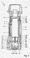
図5は、本発明による制御デバイス28を含む挿入された容器2を有する本発明の好ましい実施形態によるネブライザ1を概略断面図に示している。
FIG. 5 shows a schematic cross-sectional view of a
ネブライザ1は、好ましくは、表示デバイス25を含む。好ましくは、表示デバイス25は、(下側)ハウジング部分18内に位置付けられるか又は配置される。
The
図5は、新たに挿入された容器3を有するネブライザ1の非引張状態又は引渡状態を示している。言い換えると、容器3は、初めて挿入されているが、何らかの流体2の引き出しの意味においてまだ使用されていない。これは、ネブライザ1が図示の容器3及び制御デバイス28を用いて引張されていないことを意味する。制御部材32は、第1の位置を離れたばかりである。
FIG. 5 shows the non-tensile state or the delivered state of the
図6は、図5と類似の概略断面図であるが、引張状態での、すなわち、流体送出又は発射のために準備されたネブライザ1を示している。制御部材32は、第2の位置にある(押される)。
FIG. 6 is a schematic cross-sectional view similar to FIG. 5, but shows a
図7はまた、非引張状態であるが、ネブライザ1の引張及び流体送出の後であり、すなわち、制御部材32が第2の位置にあるネブライザ1を、図5と類似の概略断面図に示している。
FIG. 7 also shows the
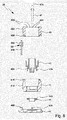
図8は、好ましい実施形態による表示デバイス25、すなわち、表示デバイス25の不可欠な構成要素を概略分解組立図に示している。図8に示す実施形態では、表示デバイス25は、ハウジング部分18に配置されている。
FIG. 8 shows the
本実施形態では、表示デバイス25は、好ましくは、起動要素40、第1の表示要素41、第2の表示要素42、表示要素41及び42の移動又は回転送りを調整するカプリング又はカプリング要素43、駆動要素44、及び/又はベース45を含む。
In this embodiment, the
好ましくは、表示デバイス25又は第1の表示要素41は、現在の容器3によって依然として実施可能な又は既に実行された使用回数を示し、又は計数し、及び/又は表示する。特に、第1の表示要素41は、好ましくはその外側又は周方向壁41A上にそれぞれの回数、マーキング、又は記号などを示す。
Preferably, the
現在の使用回数は、好ましくはネブライザハウジング24又はハウジング部分18内の関連の窓18Aを通して表示され、示され、又は見ることができる。しかし、他の構成的ソリューションも同様に実施可能である。
The current number of uses is preferably displayed, shown, or visible through the associated
第1の表示要素41は、好ましくは、スリーブ状及び/又は中空である。
The
好ましくは、第1の表示要素41は、ネブライザ1及び/又は容器3の長手軸線又は行程(ストローク)軸線の周りで回転可能である。
Preferably, the
好ましくは、起動要素40は、表示デバイス25又は第1の表示要素41を駆動し、起動し、又は回転送りする。特に、起動要素40は、容器3及び制御デバイス28の軸線方向又は行程移動を望ましい回転(段階的)移動に変換する。
Preferably, the
起動要素40は、好ましくは、ネブライザ1又は容器3及び/又は制御デバイス28の長手軸線又は行程軸線に対して軸線方向に移動可能である。
The
好ましくは、起動要素40は、本質的に円筒形又はスリーブ状である。
Preferably, the
図示の実施形態では、起動要素40は、第1及び/又は第2の表示要素41、42内で起動要素40を外側及び/又は軸線方向に案内するための好ましくは外側の好ましくはリング又はスリーブ状の部分を含む。
In the illustrated embodiment, the
特に、起動要素40は、制御デバイス28又は制御部材32と当接及び/又はそれを起動又はそれと協働するための内側に突出した及び/又はスリーブ状の起動部分を含む。
In particular, the
好ましくは、環状又はリング状空間が、起動要素40の外側部分と内側部分の間に形成され、容器3及び制御デバイス28が下側位置(ネブライザ1の引張位置)へと移動する時、又は容器3が表示デバイス25に近づいている時に、図6に示すように、制御デバイス28の好ましくはスリーブ状のハウジング31がこの空間の中に突出するか又は移動することができるように構成されている。
Preferably, when an annular or ring-shaped space is formed between the outer and inner portions of the
好ましくは、起動要素40又はその内側部分は中空であり、容器3及び制御デバイス28が下側位置(ネブライザ1の引張位置)へと移動する時、又は容器3が表示デバイス25に近づいている時に、図6に示すように、制御デバイス28の中心部分33が起動要素40又はその内側部分の中に移動することができるように構成されている。
Preferably, the
起動要素40は、好ましくは、第1の表示要素41及び/又は第2の表示要素42内に及び/又はそれと同軸に配置される。
The
図示の実施形態では、起動要素40は、特に軸線方向に延びて、可撓性であり、かつ周方向に傾斜している少なくとも1つ、ここでは2つの起動アーム40Aを含む又は保持する。少なくとも1つの起動アーム40Aは、容器3又は制御デバイス28がネブライザ1の中に挿入される時に、起動要素40が図面の上向きに及び/又は容器3又は制御デバイス28に向けて押されるように、軸線方向(行程軸線)に、ここでは駆動要素44に対して付勢される。
In the illustrated embodiment, the
少なくとも1つの起動アーム40Aは、図7に示す上側位置から図5及び6に示す下側位置までの起動要素40の下向き移動が、少なくとも1つの起動アーム40Aが応力を印加されて曲がり、それによって起動要素40と駆動要素44の間で相対回転を引き起こすという結果をもたらすように、駆動要素44と、特に好ましくは駆動要素44の軸線方向面上又は端面上の傾斜した及び/又は非対称凹部又は歯44A(図8に概略的に示す)と協働する。この相対回転のため、起動要素40及び駆動要素44の一方は、他方のみが回転することができるように回転に対して確実に固定又は保持される。好ましくは、駆動要素44は回転できず、起動要素40は、少なくとも1つの起動アーム40Aの湾曲により回転する。(起動要素40の回転段階は、次に、相応の結合により第1の表示要素41の回転送り(及び/又は同軸回転)を引き起こす。好ましくは、起動要素40の回転は、少なくとも1つの起動アーム40Aにかかる応力が緩和される時/少なくとも1つの起動アーム40Aが再度まっすぐになる時に逆になる)。これに代えて、起動要素40は、回転に対して固定され、望ましい回転方向に駆動要素44を回転又は回転送りする。駆動要素44は、次に、第1の表示デバイス41と回転可能に結合され、好ましくは、同軸的に回転することができる。特に、駆動要素44は、第1の表示要素41に又は少なくとも部分的にその中に配置され、及び/又はハウジング部分18の下端を形成する軸方向端部又はベース45上の第1の表示要素41に対して(下側)回転軸受を形成する(駆動要素44の回転固定の場合、駆動要素44は、好ましくは、ベース45によって形成される)。
The at least one
しかし、他の構成的ソリューションも同様に実施可能である。例えば、起動要素40はまた、表示要素41又はあらゆる他の構成要素の内側周方向壁に形成された、傾斜した歯又は非対称歯又はコーヴ(coves)などの中に係合することによって、表示デバイス25又はその第1の表示要素41と協働又はそれを駆動することができる。
However, other constructive solutions can be implemented as well. For example, the
ラチェット機構(図示せず)は、特に、流体送出又は発射中に起動要素40がその上側位置の中に移動して戻る時に、第1の表示要素41及び/又は(回転可能な駆動要素44の場合は)駆動要素44が反対方向に回転することを防止し、及び/又は自由な回転を防止するように提供することができる。
The ratchet mechanism (not shown) of the
ネブライザ1は、容器3を挿入又は取り替えるために開く又は取り外すことができるハウジング部分18を含む。
The
好ましくは、ハウジング部分18は、キャップ状であり、及び/又はベース45によってその下端で閉鎖される。特に、ベース45は、ハウジング部分18に分離不能に接続される。
Preferably, the
起動要素40は、それがその上側及び下側位置間で軸線方向に移動することができるが、回転できないように保持される又はそれがその回転移動が制限される(すなわち、第1の表示要素41を例えば回転送りするために限られたステップで回転することができるに過ぎない)ように保持されるように、好ましくは、ハウジング部分18又は表示デバイス25において、案内される。非回転案内又は回転制限は、例えば、起動要素40の対応する開口部の中に係合する回転不能な断面を有するベース45から軸線方向に突出した手段及び案内部分45Aによって達成することができる。しかし、起動要素40の望ましい軸線方向移動及び非回転案内又は回転制限を達成するための、例えば協働又は係合する1又は2以上の軸線方向に延びるリブ又は溝による、他の構成的ソリューションも実施可能である。
The
好ましくは、表示デバイス25又は第2の表示要素42は、ネブライザ1と共に依然として使用することができる又は既に使用された容器3の数を示し、又は計数し、及び/又は表示する。特に、第2の表示要素42は、好ましくは、その外側又は周方向壁42A上に、それぞれの数、マーキング、又は記号などを示す。
Preferably, the
これに代えて又はこれに加えて、表示デバイス25又はその第1の表示要素41又は第2の表示要素42は、ロック状態が達成される及び/又は容器3を取り替える必要がある時を、特に十字又は矢印などのようなそれぞれの記号を示すことによって示すことができる。
Alternatively or additionally, the
第2の表示要素42の現在の数、マーキング、又は記号などは、好ましくは、ネブライザハウジング24又はハウジング部分18の関連の窓18Bを通して見ることができる。しかし、他の構成的ソリューションも同様に実施可能である。
The current number, markings, symbols, etc. of the
第2の表示要素42は、好ましくは、スリーブ状及び/又は中空である。
The
好ましくは、第2の表示要素42は、ネブライザ1及び/又は容器3の長手軸線又は行程軸線の周りで回転可能であり、及び/又は第1の表示要素41に対して同軸的に回転可能である。
Preferably, the
好ましくは、第1の表示要素41及び第2の表示要素42は、一方が他方に隣接して軸線方向に配置される。
Preferably, one of the
第1の表示デバイス41及び第2の表示デバイス42の回転又は回転送りは、好ましい実施形態において、カプリング要素43によって、特に適切な伝達部によって、好ましくは結合される。
The rotation or rotary feed of the
図示の実施形態では、カプリング要素43は、特に心棒43Bなどによって回転可能に保持された歯車43Aを含む。
In the illustrated embodiment, the
好ましくは、カプリング要素43又は心棒43Bは、ベース45に形成された又はそれによって形成された軸受部分45Bにより、及び/又はハウジング部分18によって形成された軸受部分18Cにより、回転可能に保持される。しかし、他の構成的ソリューションも同様に実施可能である。
Preferably, the
好ましくは、ラチェット機構(図示せず)は、カプリング要素43及び/又は第2の表示要素42の自由及び/又は後方回転を防止するように提供することができる。
Preferably, a ratchet mechanism (not shown) can be provided to prevent the
第1の表示要素41は、好ましくは、表示要素41の円周の周りで部分的にのみ延び、かつカプリング要素43又は歯車43Aと噛み合うことができる外側歯部41Bを含む。
The
第2の表示要素42は、好ましくは、カプリング要素43又はその歯車43Aと常に噛み合う外側歯部42Bを含むことが好ましい。
The
カプリング又は伝達部は、ロック状態に入る又はそれを開始するために予め決められた使用回数に到達しているか又はそれを超えている時に(のみ)、第2の表示要素42が更に1ステップ回転送りされるように達成することができる。
When the coupling or transmission has reached or exceeds (only) a predetermined number of uses to enter or initiate a locked state, the
カプリング又は伝達部、特に部分歯部41Bの周方向長さは、特に、第1の表示要素41の次の回転又は回転送り段階が、ロック状態をリセット又は解除するために第2の表示要素42にもカプリング要素43を通じて伝達されるように作られる。表示デバイス25又は第1の表示要素41のこの必要な起動又は回転送りは、以後「リセット起動」と呼ぶ。
The circumferential length of the coupling or transmission, especially the
これに代えて又はこれに加えて、用語「リセット起動」は、未使用容器3が最初にネブライザ1に接続されるか又はその中に挿入される時、特に未使用容器3が内側にある状態でネブライザ1を完全に閉じる時の、表示デバイス25の第1の起動及び/又はロッキングデバイス26をアンロックする及び/又はネブライザ1を阻止解除する起動を指す。
Alternatively or additionally, the term "reset activation" refers to the condition in which the unused container 3 is inside, especially when the unused container 3 is first connected to or inserted into the
好ましくは、ネブライザ1は、ロック状態で引き渡され、すなわち、ロッキングデバイス26は、ネブライザ1の使用を阻止し、特に、ネブライザ1のあらゆる引張を阻止する。言い換えると、ネブライザ1は、引渡状態での、すなわち、接続又は挿入された容器3なしでの使用が阻止される。
Preferably, the
リセット起動は、好ましくは、第1の表示要素41が使用回数を示すか又は計数することによって再度開始すること、及び/又は表示デバイス25又は第1の表示要素41がリセットされることをもたらす。
The reset activation preferably results in the
ロック状態において、ネブライザ1は、ロッキングデバイス26によって更なる使用が阻止される。特に、ロッキングデバイス26は、ロック状態において上側部分16に対する内側部分17のあらゆる更なる引張、好ましくは、あらゆる更なる回転を阻止する。好ましくは、ネブライザ1は、容器3が挿入されていない状態で引き渡される。更に、ネブライザ1は、容器3が使用されて未使用又は新しいものに取り替える必要がある場合に、同じロック状態を取る。
In the locked state, the
未使用容器3が最初に挿入される時に、制御デバイス28又はその制御部材32は、未使用状態を示す第1の位置にある。
When the unused container 3 is first inserted, the
ネブライザ1又はそのハウジング24又はハウジング部分18を閉じる時に、制御デバイス28又は制御部材32は、完全閉鎖状態に到達する前にリセット起動を開始する又はリセット起動させる。
When closing the
特に、制御部材32は、最初は第1の位置にあり、起動要素40は、ネブライザ1又はハウジング部分18が完全に閉じる前に早くから制御部材32に対して当接する。更なる閉鎖移動中に(特に、ハウジング部分18が内側部分17の上に押される)、起動要素40は、ハウジング部分18及び/又は表示デバイス25内で軸線方向に及び/又は相対的に移動され、及び/又はリセット起動を実施し、すなわち、1ステップ(回転増分)だけ第1の表示要素41を回転送りし、これは、次に、同じく1ステップ(回転増分)だけ第2の表示要素42をカプリング(ここでは、部分歯部41B、カプリング要素43、及び歯部42B)を通じて回転送りする。
In particular, the
セキュアなリセット(起動)を保証するために、制御部材32をその第1の位置に保持する制御力は、十分に高く、特に、表示デバイス25を起動又はリセットするための力及び/又は第1の閾値を形成するロッキングデバイス26をアンロックするための力よりも高く設定しなければならない。すなわち、制御力は、第1の閾値よりも高くなければならない。
The control force for holding the
閉鎖移動中に、起動要素40は、ネブライザ1の閉鎖が完了する前にその下側(端部)位置に到達する。すなわち、最終の更なる閉鎖移動は、図5に概略的に示すようにネブライザ1が最後に完全に閉じられる時に、制御部材32をその第1の位置から出て及び/又は肩部37の上で中間位置の中に押し込む。すなわち、制御部材28を第1の位置に保持する制御力は、最終閉鎖移動中に打ち負かされる。従って、最終閉鎖移動に近づく時に、一方で下側ハウジング部分18又は表示デバイス25と他方で容器3又は制御デバイス28との間に作用する力は、ユーザによって印加される力に依存し、かつ高すぎてはならない。この力は、第2の閾値を形成し、制御力は、この第2の閾値よりも(十分に)低くなければならない。
During the closure movement, the
ネブライザ1は、依然として非引張状態にあり、すなわち、初期又は以前のロック状態中であり、容器挿入又は取替中であり、ネブライザ1の閉鎖中であることに注意しなければならない。
It should be noted that the
表示デバイス25のリセット起動は、表示デバイス25又はその第2の表示要素42がロック状態又は位置からアンロック状態又は位置までリセットされる又は更に移動されるほど十分に早期に起こる。
The reset activation of the
図6は、引張状態でのネブライザ1を示している。最初の引張行程(図5に示す非引張状態から始まる容器3及び制御デバイス28の下向き移動)中に、起動要素40は、制御部材32を図5に示す中間状態から図6に示す第2の位置の中に押し込む。特に、制御部材32は、軸線方向に移動される又は押下される(制御デバイス28又はそのハウジング31の中に、又は第2の位置の中に)。既に説明したように、制御部材32は、好ましくは、この押圧動作が最初の引張中にのみ起こるように第2の位置に保持される。
FIG. 6 shows the
任意的な穿孔要素22が設けられる場合に、最初の引張中に穿孔要素22を自動的に起動することが可能である。例えば、穿孔要素22は、図6に概略的に示すように、好ましくは案内部分45Aにより、最初の使用又は引張中にハウジング部分18又は表示デバイス25に対する容器3又は制御デバイス28の軸線方向移動によってその穿孔位置の中に軸線方向に押し込むことができると考えられる。しかし、他の構成的ソリューションも同様に実施可能である。
If an
図7は、最初の又は複数の使用の後の非引張状態でのネブライザ1を示している。制御デバイス28又は制御部材32が、使用された状態を示す第2の位置に留まることを見ることができる。
FIG. 7 shows the
上述のように、ロッキングデバイス26は、好ましくは、表示デバイス25及び/又は制御デバイス28により、好ましくは表示デバイス25を通じて制御デバイス28によって制御される又は起動される。すなわち、表示デバイス25は、好ましくは、図示のかつ好ましい実施形態においてロッキングデバイス26を制御又は起動する。しかし、制御デバイス28はまた、直接に又は追加の起動要素などを通じてロッキングデバイス26を制御又は起動することもできる。
As mentioned above, the locking
ロッキングデバイス26は、好ましくは、内側部分17に配置される。
The locking
ロッキングデバイス26は、ロッキング要素46を制御するための好ましくは制御要素47を含む。
The locking
好ましくは、ロッキング要素46は、図5〜7に示す非ロッキング位置から下向きにロッキング位置へと軸線方向に付勢されるバネによって形成される。
Preferably, the locking
ロッキング要素46又はバネは、好ましくは、それが上側ハウジング部分16に形成されたカウンター凹部、好ましくはポケット16Aの中に自動的に拡張又は係合し、ロック状態でネブライザ1の更なる引張を阻止するように構成される。
The locking
ロッキング要素46は、内側部分17において軸線方向に移動可能に保持され、特に、ロック位置の中に又は阻止するために下向きにそれ自体によって又は個別のバネによって付勢されることに注意しなければならない。
It should be noted that the locking
ネブライザ1又はハウジング部分16は、好ましくは、ロッキングデバイス26又はロッキング要素46が各可能な回転端部位置での更なる使用に対してネブライザ1を阻止することができるように、180°だけオフセットされた2つの係合凹部又は部分、特に2つのポケット16Aを含む。この状況では、ネブライザ1又はその内側部分17及びハウジング部分18は、各引張中に180°だけ回転されることに注意しなければならない。
The
ロッキングデバイス26又は制御要素47は、ネブライザ1が完全に閉じられる及び/又は表示デバイス25がロック状態に入っていない限り、特に、表示デバイス25又はその第2の表示要素42又はその突起42Cが制御要素47を押す、すなわち、ロッキング要素46が図5〜7に示すように上側又は非ロッキング位置にある限り、ロッキング要素46を上側又は非ロッキング位置に保つ又は保持するように構成される。
The locking
図8において、一方で表示デバイス25又はその第2の表示要素42及び他方で制御要素47の協働は、表示デバイス25の構成要素の断面図に概略的に示されている。
In FIG. 8, the cooperation of the
特に、第2の表示要素42は、少なくとも1つの突起42C及び/又は凹部42D、特にこれに代えて複数の突起42C及び凹部42D、を好ましくはロッキングデバイス26又はその制御要素47と協働するか又はそれを軸線方向に起動するためにその端部又は軸線方向面及び/又はあらゆる他の適切な位置に含む。図9において、第2の表示要素42の実施形態は、斜視図に示されている。
In particular, does the
図8に示すように、好ましくは、制御要素47は、制御要素47が図5〜7に示すその上側位置に保持されるか又は押される時にロッキング要素46を非ロッキング位置の中に上向きに押すためにロッキング要素46に向けて延びる制御部分47Aを含む又はそれに接続される。
As shown in FIG. 8, preferably, the
ロック状態が達成されるか又はロック状態に入ることになる時に、表示デバイス25又はその第2の表示要素42は、突起42Cがそれ以上制御要素47を支持しないように更に1回の回転ステップだけ回転送りされる。その結果、制御要素47は、特にロッキング要素46及び/又はいずれかの他のバネの付勢力に起因して、(次の)凹部42Dの中に軸線方向下向きに移動することができる。この軸線方向移動は、ロッキングデバイス26又はそのロッキング要素46がロック状態で更なる使用又は引張に対してネブライザ1を(自動的に)阻止することができるように、ロッキング要素46がロック位置の中に、特に半径方向に、好ましくはポケット16Aの中に移動することを可能にする。
When the locked state is achieved or entered into the locked state, the
上述のように、ロッキングデバイス26のロック状態は、使用された容器3が未使用容器3と取り替えられ、かつネブライザ1が完全に閉じられた時にリセット又は解除することができる。特に、未使用容器3(制御部材32が第1の位置にある制御デバイス28と共に)の挿入は、突起42Cが制御要素47の下に再度移動され、かつネブライザ1を完全に閉じる時に制御要素47を軸線方向上向きに押すことができることをもたらす完全閉鎖の前に、表示デバイス25又はその第2の表示要素42が更に1ステップ回転送りされるように、既に上述したリセット起動をもたらす。すなわち、ロッキングデバイス26は、リセット又はアンロックされ、ネブライザ1は、阻止解除される。
As described above, the locked state of the
表示デバイス25は、好ましくは、ネブライザ1と共に使用されたか又は依然として使用することができる容器3の数を計数することに注意しなければならない。容器3の予め決められた数、例えば、4個、5個、又は6個の容器3に到達した場合に、ネブライザ1は、好ましくは、あらゆる更なる使用に対して最終的に阻止される。
It should be noted that the
ネブライザ1の上述の最終阻止は、表示デバイス25を通じて、特に、交互する凹部42Dの最終又は最後の凹部42Fが、表示デバイス25のいずれの最終リセット起動もロッキングデバイス26のリセット又はアンロックをもたらさないように、周方向により長く作られるということで達成することができる。
The above-mentioned final blockage of the
上記説明に鑑みて、容器3のみをその関連の制御デバイス28と共に通常の使用の後で取り替える必要があることに注意しなければならない。ハウジング部分18と表示デバイス25とを含むネブライザ1は、複数の容器3に対して再使用することができる。
In view of the above description, it should be noted that only the container 3 needs to be replaced after normal use with its associated
ネブライザ1は、それを予め決められた使用回数が現在の容器3によって到達されるか又は超過された後でのみ開くことができるように構成することができることに注意しなければならない。早期開放に対するこのロッキングは、同様に表示デバイス25により、例えば、予め決められた使用回数が現在の容器3によって到達されるか又は超過されるまで保持要素19の押下をロックすることにより、制御することができる。
It should be noted that the
独立型機器などとは異なり、提案するネブライザ1は、好ましくは、携帯式であるように設計され、特に移動式手動デバイスである。
Unlike stand-alone devices and the like, the proposed
しかし、提案するソリューションは、本明細書で具体的に説明するネブライザ1だけではなく、他のネブライザ又は吸入器、例えば、粉末吸入器又はいわゆる計量された投薬吸入器に使用することもできる。
However, the proposed solution can be used not only for the
好ましくは、流体2は、上述のような液体、特に、水性医薬製剤又はエタノール医薬薬剤である。しかし、それはまた、何らかの他の医薬薬剤又は懸濁液などである場合がある。
Preferably, the
代替実施形態により、流体2はまた、粒子又は粉末を含むことができる。この場合に、排出ノズル12の代わりに、何らかの他の種類の供給デバイス、特に、流体や粉末などをマウスピース13に供給するための排出開口部(図示せず)又は供給チャネル(図示せず)を設けることができる。任意的な空気供給開口部15は、次に、マウスピース13を通して呼吸又は吸入するのに十分な容積の空気流を発生又は可能にするために、好ましくは、並行して周囲空気を供給するように機能する。
According to an alternative embodiment, the
必要に応じて、流体2は、推進剤ガスによって噴霧化することもできる。
If desired, the
好ましい薬液2の好ましい原料及び/又は製剤は、特に、本明細書に引用によって組み込まれているWO 2009/115200 A1、好ましくは25〜40ページに、又はEP 2,614,848 A1、段落0040〜0087に列挙されている。特に、それらは、水性又は非水性溶液、混合液、又はエタノール含有又はいかなる溶剤も含まない製剤などである場合がある。
Preferred raw materials and / or formulations of
参照番号のリスト
1 ネブライザ
2 流体
3 容器
4 バッグ
5 圧力発生器
6 ホルダ
7 駆動バネ
8 阻止要素
9 搬送チューブ
10 逆止弁
11 圧力チャンバ
12 ノズル
13 マウスピース
14 エアロゾル
15 空気供給開口部
16 上側ハウジング部分
16A ポケット
17 内側部分
17A 内側部分の上側部分
17B 内側部分の下側部分
18 ハウジング部分(下側部分)
18A 第1の窓
18B 第2の窓
18C 軸受け部分
19 保持要素
20 曝気バネ
21 容器ベース
22 穿孔要素
23 通気孔
24 ネブライザハウジング
25 表示デバイス
26 ロッキングデバイス
27 ロッキング要素
28 制御デバイス
29 容器ハウジング
30 容器ヘッド
31 ハウジング(制御デバイス)
32 制御部材
33 中心部分
34 開口部
35 係合部分
36 凹部
37 肩部
38 スリット
39 ノーズ
40 起動要素
40A 起動アーム
41 第1の表示要素
41A 壁
41B 歯部
42 第2の表示要素
42A 壁
42B 歯部
42C 突起
42D 最後の凹部
43 カプリング要素
43A 歯車
43B 心棒
44 駆動要素
44A 歯
45 ベース
45A 案内部分
45B 軸受部分
46 ロッキング要素
47 制御要素
47A 制御部分
List of
32
Claims (19)
前記流体(2)を収容する前記容器(3)と、を備え、前記ネブライザ(1)及び前記容器(3)はそれぞれ長手軸線を有するシステムであって、
前記ネブライザ(1)は、
ハウジング(24)と、前記容器(3)を挿入又は取り替えるために前記ハウジング(24)から取り外すことができる下側ハウジング部分(18)と、
前記容器(3)を用いて実行されたか又は依然として実施可能な使用回数を計数する又は示すための表示デバイス(25)を備え、該表示デバイス(25)は 前記ネブライザ(1)の長手軸線の周りで回転可能な回転可能部材(42)を備え、該回転可能部材(42)の上面は、前記表示デバイス(25)の周方向に沿って配置された少なくとも1つの突起(42C)と少なくとも1つの凹部(42D)を有し、
前記表示デバイス(25)により計数された又は示された前記容器(3)を用いて実行されたか又は依然として実施可能な使用回数に基づいて、1つの前記容器(3)の予め定められた使用の後にロック状態で該容器(3)を用いる更なる使用に対して前記ネブライザ(1)を阻止するためのロッキングデバイス(26)を含み、
前記ロッキングデバイス(26)は、前記容器(3)を用いる更なる使用に対して前記ネブライザ(1)を阻止する第1の位置と前記ネブライザ(1)の使用を阻止しない第2の位置との間で、軸線方向に移動可能な制御要素(47)を備え、該制御要素は、前記表示デバイス(25)へと延在して、前記表示デバイス(25)の前記回転可能部材(42)の上面に当接し、
前記容器(3)は、該容器(3)の未使用状態を示すための制御デバイス(28)を含み、
前記制御デバイス(28)は、制御部材(32)を備え、該制御部材(32)は、前記容器(3)の未使用状態のときにある第1の位置から、第2の位置に移動可能であり、前記第1の位置にある前記制御部材(32)は前記容器(3)の前記未使用状態を示し、前記第2の位置にある前記制御部材(32)は前記容器(3)が既に使用された状態を示し、
前記制御デバイス(28)は、未使用容器(3)が前記ネブライザ(1)に最初に取付けられ、前記下側ハウジング部分(18)が前記ハウジング(24)に取付けられた時に、前記表示デバイス(25)の軸線方向に移動可能な部材(40)を軸線方向に押して、前記表示デバイス(25)をリセットし、前記制御部材(32)は第1の位置において前記表示デバイス(25)の前記軸線方向に移動可能な部材(40)を押して、前記表示デバイス(25)の前記回転可能部材(42)を回転送りし、
前記回転送りにより、前記制御要素(47)が当接する前記表示デバイス(25)の前記回転可能部材(42)の上面の位置が変わり、前記突起(42C)及び前記凹部(42D)により、前記制御要素(47)は前記第1の位置から前記第2の位置へと軸線方向に移動し、その結果、前記ネブライザ(1)の使用が阻止されない、ことを特徴とするシステム。 A nebulizer (1) for spraying fluid (2) from a replaceable container (3),
Said fluid said container (3) for accommodating the (2), wherein the nebulizer (1) and the container (3) is a system that each have a longitudinal axis,
The nebulizer (1) is
A housing (24) and a lower housing portion (18) that can be removed from the housing (24) to insert or replace the container (3).
A display device (25) for counting or indicating the number of uses performed or still feasible with the container (3) is provided around the longitudinal axis of the nebulizer (1). The rotatable member (42) is provided with a rotatable member (42), and the upper surface of the rotatable member (42) has at least one protrusion (42C) arranged along the circumferential direction of the display device (25) and at least one. Has a recess (42D)
A predetermined use of one of the containers (3) based on the number of uses performed or still feasible with the container (3) counted or indicated by the display device (25). Includes a locking device (26) for blocking the nebulizer (1) for further use with the container (3) later in the locked state.
The locking device (26) has a first position that blocks the nebulizer (1) and a second position that does not block the use of the nebulizer (1) for further use with the container (3). A control element (47) that is movable in the axial direction is provided between the control elements, which extend to the display device (25) and of the rotatable member (42) of the display device (25). In contact with the top surface
The container (3) includes a control device (28) for indicating an unused state of the container (3).
The control device (28) includes a control member (32), and the control member (32) can be moved from a first position when the container (3) is in an unused state to a second position. The control member (32) at the first position indicates the unused state of the container (3), and the control member (32) at the second position is the container (3). Indicates a state that has already been used
The control device (28) is the display device ( 28) when the unused container (3) is first attached to the nebulizer (1) and the lower housing portion (18) is attached to the housing (24). The member (40) movable in the axial direction of the 25) is pushed in the axial direction to reset the display device (25), and the control member (32) is in the first position with the axis of the display device (25). By pushing the directionally movable member (40), the rotatable member (42) of the display device (25) is rotationally fed.
The rotation feed changes the position of the upper surface of the rotatable member (42) of the display device (25) with which the control element (47) abuts, and the protrusion (42C) and the recess (42D) control the control. A system characterized in that the element (47) moves axially from the first position to the second position, and as a result, the use of the nebulizer (1) is not blocked .
ことを特徴とする請求項1から請求項4のいずれか1項に記載のシステム。 The control device (28) includes a central bolt (33) that extends axially through the opening (34) of the control member (32) and projects onto the control member (32).
The system according to any one of claims 1 to 4 , wherein the system is characterized by the above.
Applications Claiming Priority (3)
| Application Number | Priority Date | Filing Date | Title |
|---|---|---|---|
| EP15020223.2 | 2015-11-09 | ||
| EP15020223 | 2015-11-09 | ||
| PCT/EP2016/076485 WO2017080895A1 (en) | 2015-11-09 | 2016-11-03 | Nebulizer and container |
Publications (3)
| Publication Number | Publication Date |
|---|---|
| JP2018536475A JP2018536475A (en) | 2018-12-13 |
| JP2018536475A5 JP2018536475A5 (en) | 2019-12-19 |
| JP6900372B2 true JP6900372B2 (en) | 2021-07-07 |
Family
ID=54540799
Family Applications (1)
| Application Number | Title | Priority Date | Filing Date |
|---|---|---|---|
| JP2018523431A Active JP6900372B2 (en) | 2015-11-09 | 2016-11-03 | Nebulizer and container |
Country Status (4)
| Country | Link |
|---|---|
| US (1) | US10898661B2 (en) |
| EP (1) | EP3374011B1 (en) |
| JP (1) | JP6900372B2 (en) |
| WO (1) | WO2017080895A1 (en) |
Families Citing this family (3)
| Publication number | Priority date | Publication date | Assignee | Title |
|---|---|---|---|---|
| AU2018303701B2 (en) * | 2017-07-21 | 2023-09-21 | Boehringer Ingelheim International Gmbh | Nebulizer and container |
| WO2019016410A1 (en) * | 2017-07-21 | 2019-01-24 | Boehringer Ingelheim International Gmbh | The present invention relates to a nebulizer according to the preamble of claim 1 |
| CA3225039A1 (en) * | 2021-07-20 | 2023-01-26 | Jurgen Rawert | Inhalation device system with a counting and blocking assembly |
Family Cites Families (20)
| Publication number | Priority date | Publication date | Assignee | Title |
|---|---|---|---|---|
| SE7415243L (en) * | 1973-12-26 | 1975-06-27 | Ciba Geigy Ag | |
| US5482030A (en) * | 1994-06-13 | 1996-01-09 | Klein; David | Aerosol and non-aerosol spray counter |
| DE4428434A1 (en) | 1994-08-11 | 1996-02-15 | Boehringer Ingelheim Kg | Sealing cap and method for filling gas-free containers |
| ES2177771T3 (en) * | 1995-03-14 | 2002-12-16 | Siemens Ag | ULTRASONIC ATOMIZING DEVICE WITH REMOVABLE PRECISION DOSAGE UNIT. |
| DE19549033C1 (en) * | 1995-12-28 | 1997-05-28 | Boehringer Ingelheim Int | Mechanical counter for a dosing device |
| SE9902672D0 (en) | 1999-07-12 | 1999-07-12 | Astra Ab | Delivery device |
| US7621273B2 (en) * | 2003-10-28 | 2009-11-24 | Trudell Medical International | Indicating device with warning dosage indicator |
| EP3662948B1 (en) | 2004-03-10 | 2022-11-09 | Glaxo Group Limited | A dispensing device |
| CN101247897B (en) | 2005-08-24 | 2013-06-12 | 贝林格尔·英格海姆国际有限公司 | Atomiser |
| JP5599772B2 (en) | 2008-03-17 | 2014-10-01 | ベーリンガー インゲルハイム インターナショナル ゲゼルシャフト ミット ベシュレンクテル ハフツング | Reservoir and nebulizer |
| JP5075752B2 (en) * | 2008-06-30 | 2012-11-21 | 株式会社吉野工業所 | Aerosol container |
| DE102010047847B4 (en) | 2010-09-30 | 2013-04-04 | Aptar Radolfzell Gmbh | Discharge device for discharging liquids |
| WO2012130757A1 (en) * | 2011-04-01 | 2012-10-04 | Boehringer Ingelheim International Gmbh | Medical device comprising a container |
| WO2012161685A1 (en) | 2011-05-23 | 2012-11-29 | Boehringer Ingelheim International Gmbh | Nebulizer |
| US10080853B2 (en) * | 2011-05-23 | 2018-09-25 | Boehringer Ingelheim International Gmbh | Nebulizer |
| EP2614848B1 (en) | 2012-01-13 | 2020-07-01 | Boehringer Ingelheim International GmbH | Inhaler and capsule for an inhaler |
| EP3125821B1 (en) | 2014-03-31 | 2023-06-07 | Boehringer Ingelheim Vetmedica GmbH | Insert for an inhaler |
| EP3139982B1 (en) | 2014-05-07 | 2022-02-16 | Boehringer Ingelheim International GmbH | Nebulizer |
| KR102443737B1 (en) | 2014-05-07 | 2022-09-19 | 베링거 인겔하임 인터내셔날 게엠베하 | Container, nebulizer and use |
| DK3139984T3 (en) | 2014-05-07 | 2021-07-19 | Boehringer Ingelheim Int | Atomizer |
-
2016
- 2016-11-03 EP EP16793804.2A patent/EP3374011B1/en active Active
- 2016-11-03 JP JP2018523431A patent/JP6900372B2/en active Active
- 2016-11-03 WO PCT/EP2016/076485 patent/WO2017080895A1/en active Application Filing
- 2016-11-08 US US15/345,646 patent/US10898661B2/en active Active
Also Published As
| Publication number | Publication date |
|---|---|
| EP3374011B1 (en) | 2023-07-19 |
| JP2018536475A (en) | 2018-12-13 |
| EP3374011A1 (en) | 2018-09-19 |
| WO2017080895A1 (en) | 2017-05-18 |
| US10898661B2 (en) | 2021-01-26 |
| US20170128681A1 (en) | 2017-05-11 |
Similar Documents
| Publication | Publication Date | Title |
|---|---|---|
| JP6594340B2 (en) | Nebulizer, display device, and container | |
| JP6732981B2 (en) | Nebulizer | |
| JP6580070B2 (en) | Container, nebulizer, and use | |
| JP6559157B2 (en) | Nebulizer | |
| EP2504052B1 (en) | Nebulizer | |
| MX2012005878A (en) | Nebulizer. | |
| JP6900372B2 (en) | Nebulizer and container | |
| JP6961600B2 (en) | Nebulizer | |
| NZ724723B2 (en) | Nebulizer, indicator device and container |
Legal Events
| Date | Code | Title | Description |
|---|---|---|---|
| A521 | Request for written amendment filed |
Free format text: JAPANESE INTERMEDIATE CODE: A523 Effective date: 20191105 |
|
| A621 | Written request for application examination |
Free format text: JAPANESE INTERMEDIATE CODE: A621 Effective date: 20191105 |
|
| A977 | Report on retrieval |
Free format text: JAPANESE INTERMEDIATE CODE: A971007 Effective date: 20201026 |
|
| A131 | Notification of reasons for refusal |
Free format text: JAPANESE INTERMEDIATE CODE: A131 Effective date: 20201130 |
|
| A601 | Written request for extension of time |
Free format text: JAPANESE INTERMEDIATE CODE: A601 Effective date: 20210226 |
|
| A521 | Request for written amendment filed |
Free format text: JAPANESE INTERMEDIATE CODE: A523 Effective date: 20210428 |
|
| TRDD | Decision of grant or rejection written | ||
| A01 | Written decision to grant a patent or to grant a registration (utility model) |
Free format text: JAPANESE INTERMEDIATE CODE: A01 Effective date: 20210517 |
|
| A61 | First payment of annual fees (during grant procedure) |
Free format text: JAPANESE INTERMEDIATE CODE: A61 Effective date: 20210616 |
|
| R150 | Certificate of patent or registration of utility model |
Ref document number: 6900372 Country of ref document: JP Free format text: JAPANESE INTERMEDIATE CODE: R150 |