JP6899237B2 - Stereoscopic image display device - Google Patents
Stereoscopic image display device Download PDFInfo
- Publication number
- JP6899237B2 JP6899237B2 JP2017060647A JP2017060647A JP6899237B2 JP 6899237 B2 JP6899237 B2 JP 6899237B2 JP 2017060647 A JP2017060647 A JP 2017060647A JP 2017060647 A JP2017060647 A JP 2017060647A JP 6899237 B2 JP6899237 B2 JP 6899237B2
- Authority
- JP
- Japan
- Prior art keywords
- light source
- stereoscopic image
- point light
- display device
- image display
- Prior art date
- Legal status (The legal status is an assumption and is not a legal conclusion. Google has not performed a legal analysis and makes no representation as to the accuracy of the status listed.)
- Active
Links
- 230000003287 optical effect Effects 0.000 claims description 18
- 230000000007 visual effect Effects 0.000 claims description 14
- 238000010586 diagram Methods 0.000 description 9
- 230000000694 effects Effects 0.000 description 9
- 230000009471 action Effects 0.000 description 8
- 230000015572 biosynthetic process Effects 0.000 description 8
- 238000000034 method Methods 0.000 description 8
- 230000008859 change Effects 0.000 description 3
- NJPPVKZQTLUDBO-UHFFFAOYSA-N novaluron Chemical compound C1=C(Cl)C(OC(F)(F)C(OC(F)(F)F)F)=CC=C1NC(=O)NC(=O)C1=C(F)C=CC=C1F NJPPVKZQTLUDBO-UHFFFAOYSA-N 0.000 description 2
- GOJUJUVQIVIZAV-UHFFFAOYSA-N 2-amino-4,6-dichloropyrimidine-5-carbaldehyde Chemical group NC1=NC(Cl)=C(C=O)C(Cl)=N1 GOJUJUVQIVIZAV-UHFFFAOYSA-N 0.000 description 1
- 230000008901 benefit Effects 0.000 description 1
- 230000005540 biological transmission Effects 0.000 description 1
- 230000003247 decreasing effect Effects 0.000 description 1
- 230000006866 deterioration Effects 0.000 description 1
- 238000009792 diffusion process Methods 0.000 description 1
- 230000012447 hatching Effects 0.000 description 1
- 230000006872 improvement Effects 0.000 description 1
- 238000009434 installation Methods 0.000 description 1
- 239000004973 liquid crystal related substance Substances 0.000 description 1
- 230000004048 modification Effects 0.000 description 1
- 238000012986 modification Methods 0.000 description 1
- 230000002093 peripheral effect Effects 0.000 description 1
- 230000004044 response Effects 0.000 description 1
Images


Description
本発明は、インテグラルフォトグラフィ(IP:Integral Photography)方式の立体映像表示装置に関する。 The present invention relates to an integral photography (IP) type stereoscopic image display device.
一般的なIP方式では、ディスプレイ前面にレンズアレイを設置し、対応する要素画像群をディスプレイに表示することで、水平・垂直方向に視差のある裸眼立体映像を表示する。 In the general IP method, a lens array is installed on the front surface of the display, and the corresponding element image group is displayed on the display to display a naked-eye stereoscopic image having parallax in the horizontal and vertical directions.
また、IP方式では、レンズアレイを用いる代わりに、点光源をバックライトとして用いて、その前面にディスプレイを設置して立体映像を表示することも可能である。点光源をバックライトとして用いる手法は、レンズアレイの表面形状や反射特性の影響など、レンズアレイに起因する画質の低下要因が少ないという利点がある。また、光の透過と拡散を制御する素子をディスプレイの前段に配置することで、2次元画像と3次元画像を切り替えることも可能である。 Further, in the IP method, instead of using a lens array, it is possible to use a point light source as a backlight and install a display in front of the point light source to display a stereoscopic image. The method of using a point light source as a backlight has an advantage that there are few factors of deterioration in image quality due to the lens array, such as the influence of the surface shape and reflection characteristics of the lens array. It is also possible to switch between a two-dimensional image and a three-dimensional image by arranging an element that controls light transmission and diffusion in front of the display.
ここで、LEDアレイとレンズアレイを用いて、レンズアレイの焦点面に点光源を形成する手法が提案されている(非特許文献1)。また、平行光源とレンズアレイを用いて、点光源を形成する手法も提案されている(非特許文献2)。この非特許文献2に記載の手法は、2つの平行光源を異なる位置に設置し、時間分割で切り替えることで、立体映像の視域角を拡大することも可能である。 Here, a method of forming a point light source on the focal plane of a lens array using an LED array and a lens array has been proposed (Non-Patent Document 1). Further, a method of forming a point light source by using a parallel light source and a lens array has also been proposed (Non-Patent Document 2). In the method described in Non-Patent Document 2, two parallel light sources are installed at different positions and switched by time division, so that the viewing range angle of the stereoscopic image can be expanded.
しかし、非特許文献1,2に記載の手法では、点光源の配光特性が固定であるため、視域角や解像度といった立体映像の表示特性は固定され、表示中に制御することができない。多様な立体映像コンテンツを表示するためには、コンテンツに応じて視域角や解像度などの立体映像の表示特性を表示中に制御できることが好ましい。 However, in the methods described in Non-Patent Documents 1 and 2, since the light distribution characteristics of the point light source are fixed, the display characteristics of the stereoscopic image such as the viewing area angle and the resolution are fixed and cannot be controlled during the display. In order to display various stereoscopic video contents, it is preferable that the display characteristics of the stereoscopic video such as the viewing area angle and the resolution can be controlled during the display according to the contents.
そこで、本発明は、立体映像の表示特性を表示中に制御できる立体映像表示装置を提供することを課題とする。 Therefore, an object of the present invention is to provide a stereoscopic image display device capable of controlling the display characteristics of a stereoscopic image during display.
前記した課題に鑑みて、本発明に係る立体映像表示装置は、点光源群をバックライトとして用いて、立体映像を表示するインテグラルフォトグラフィ方式の立体映像表示装置であって、点光源の配光特性を表すマスク画像が要素レンズに対応して配列された点光源群形成用パターンを投影する投影手段と、前記投影手段が投影した点光源群形成用パターンを平行光として出射する平行光出射手段と、前記要素レンズが2次元状に配列され、前記平行光出射手段からの平行光を各要素レンズの焦点に集光することで、前記点光源群を形成するレンズアレイと、要素画像群を表示する空間光変調素子と、制御手段とを備え、前記マスク画像の全部又は一部が、前記投影手段が最大輝度の光を投影する矩形状の前記非マスク領域と、前記非マスク領域の周囲に位置し、前記投影手段が光を投影しない矩形状の外形のマスク領域とを有する構成とした。 In view of the above problems, the stereoscopic image display device according to the present invention is an integral photography type stereoscopic image display device that displays a stereoscopic image by using a point light source group as a backlight, and has a point light source arrangement. a projection means for projecting a light source group forming patterns that mask image image are arranged in correspondence with the element lenses representing light characteristics, the parallel light that emits the projection means source group forming pattern that is projected as parallel light The emitting means, the lens array in which the element lenses are arranged in a two-dimensional shape, and the parallel light from the parallel light emitting means is focused on the focal point of each element lens to form the point light source group, and the element image. A spatial light modulation element for displaying a group and a control means are provided, and all or a part of the mask image is a rectangular non-masked region on which the projection means projects the light having the maximum brightness, and the non-masked region. the positioned around said projection means has a structure that having a mask area of the rectangular outer shape without projecting light.
かかる構成によれば、立体映像表示装置は、制御手段によって、前記マスク画像に含まれる非マスク領域の位置及び大きさと、前記非マスク領域の光強度分布と、前記非マスク領域が含まれるマスク画像の投影間隔と、前記マスク画像の投影方向との何れか1以上を制御する。
このように、立体映像表示装置は、立体映像の表示中、所望のマスク画像を投影手段が投影するので、点光源の配光特性を任意に制御することができる。
According to such a configuration, a stereoscopic image display device, the control means, the position and size of the unmasked regions included in the mask image, and the light intensity distribution of the non-masked region, the mask image including the said unmasked region Any one or more of the projection interval of the above and the projection direction of the mask image is controlled.
As described above, in the stereoscopic image display device, since the projection means projects a desired mask image during the display of the stereoscopic image, the light distribution characteristics of the point light source can be arbitrarily controlled.
本発明によれば、以下のような優れた効果を奏する。
本発明に係る立体映像表示装置は、点光源の配光特性を任意に変更できるので、視域角や解像度といった立体映像の表示特性を、その表示中に制御することができる。
According to the present invention, the following excellent effects are obtained.
Since the stereoscopic image display device according to the present invention can arbitrarily change the light distribution characteristics of the point light source, the display characteristics of the stereoscopic image such as the viewing area angle and the resolution can be controlled during the display.
(第1実施形態)
[立体映像表示装置]
以下、本発明の各実施形態について、適宜図面を参照しながら詳細に説明する。なお、各実施形態において、同一の手段及び同一の部材には同一の符号を付し、説明を省略した。
(First Embodiment)
[Stereoscopic image display device]
Hereinafter, each embodiment of the present invention will be described in detail with reference to the drawings as appropriate. In each embodiment, the same means and the same members are designated by the same reference numerals, and the description thereof will be omitted.
図1を参照し、本発明の第1実施形態に係る立体映像表示装置1の概略について説明する。
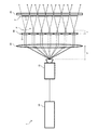
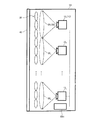
立体映像表示装置1は、点光源群Pをバックライトとして用いて、IP方式で立体映像を表示するものであり、図1に示すように、プロジェクタ(投影手段)10と、コリメータレンズ(平行光出射手段)20と、レンズアレイ30と、空間光変調素子40と、制御装置(制御手段)50とを備える。
The outline of the stereoscopic image display device 1 according to the first embodiment of the present invention will be described with reference to FIG.
The stereoscopic image display device 1 displays a stereoscopic image by an IP method using a point light source group P as a backlight, and as shown in FIG. 1, a projector (projection means) 10 and a collimator lens (parallel light). The light emitting means) 20, the
プロジェクタ10は、後記する制御装置50からの制御に従って、点光源群形成用パターンを投影するものである。この点光源群形成用パターンは、点光源pの配光特性を制御するためのマスク画像であり、その詳細は後述する。本実施形態では、プロジェクタ10は、1台であることとする。また、プロジェクタ10は、コリメータレンズ20の焦点距離Fに配置され、正確に位置校正が行われていることとする。なお、点光源pの大きさは、プロジェクタ10の投影画像の1画素程度である。
The
コリメータレンズ20は、プロジェクタ10が投影した点光源群形成用パターンを平行光として出射するものである。例えば、コリメータレンズ20としては、一般的な凸レンズ、フレネルレンズをあげることができる。
The
レンズアレイ30は、コリメータレンズ20からの平行光を各要素レンズ31の焦点距離fの位置に集光することで、点光源群Pを形成するものである。このレンズアレイ30は、複数の要素レンズ31が、縦横方向や樽積み状に2次元に配列されている。例えば、要素レンズ31としては、正面視すると円形状の一般的な凸レンズや凹レンズをあげることができる。
The
空間光変調素子40は、外部(例えば、制御装置50)から入力された要素画像群Eを表示するものである。この要素画像群Eは、各要素レンズ31に対応した要素画像eで構成される。例えば、空間光変調素子40としては、液晶パネルをあげることができる。ここで、空間光変調素子40は、空間光変調素子40の画素を有効活用するため、点光源群Pによるバックライトが空間光変調素子40の全体を照射する位置に配置することが好ましい。
The spatial
制御装置50は、プロジェクタ10を制御するものである。具体的には、制御装置50は、プロジェクタ10が投影する点光源群形成用パターンについて、非マスク領域の位置、非マスク領域の大きさと、点光源形成用パターンの光強度分布、非マスク領域を有する点光源形成用パターンの投影間隔、及び、点光源形成用パターンの投影方向の何れか1以上の制御を行う。この制御装置50の詳細は後記する。
The
以上のように、立体映像表示装置1では、プロジェクタ10が点光源群形成用パターンを投影すると、コリメータレンズ20によって点光源群形成用パターンの光線が平行光となり、要素レンズ31に入射することになる。そして、要素レンズ31に入射した光線は、要素レンズ31の焦点距離fの位置に集光する。この集光点を点光源pとみなして、空間光変調素子40に要素画像群Eを表示することで、立体映像を表示することが可能となる。
As described above, in the stereoscopic image display device 1, when the
ここで、立体映像表示装置1では、点光源群Pが空間光変調素子40全体を照射するようなレンズアレイ30の特性、点光源群形成用パターンの位置や大きさ、空間光変調素子40の位置を設定することで、空間光変調素子40の画素を有効に活用することができる。
Here, in the stereoscopic image display device 1, the characteristics of the
<点光源の形成位置及び配光角>
図2を参照し、点光源pの形成位置及び配光角について説明する。
図2に示すように、点光源形成用パターンの投影方向をθとする。投影方向θは、要素レンズ31の光軸(x軸)と、点光源形成用パターンの光軸(破線で図示)とのなす角である。このとき、点光源pの形成位置(px,py)は、下記の式(1)で表される。さらに、点光源pの配光角φは、下記の式(2)で表される。
<Position of point light source and light distribution angle>
With reference to FIG. 2, the formation position and the light distribution angle of the point light source p will be described.
As shown in FIG. 2, the projection direction of the point light source forming pattern is θ. The projection direction θ is an angle formed by the optical axis (x-axis) of the
![]()
![]()
![]()
![]()
a,bはそれぞれ、点光源形成用パターンの非マスク領域の上端及び下端を表す。y軸上では、非マスク領域の上端a〜下端bの間を光線が通過する。従って、点光源形成用パターンの投影方向θや非マスク領域の大きさ(上端a〜下端b)を変更することで、点光源pの形成位置(px,py)や配光角φを制御できる。 a and b represent the upper end and the lower end of the non-masked region of the point light source forming pattern, respectively. On the y-axis, light rays pass between the upper end a and the lower end b of the unmasked region. Therefore, by changing the projection direction θ and the unmasked area size of the point source forming pattern (upper a~ bottom b), the formation position of the point light source p (p x, p y) a and distribution angle φ Can be controlled.
<点光源群形成用パターン>
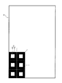
図3を参照し、点光源群形成用パターン60について説明する。
図3に示すように、点光源群形成用パターン60は、点光源形成用パターン61が要素レンズ31に対応して配列された画像である。つまり、点光源群形成用パターン60は、要素レンズ31と同一配列で、同数の点光源形成用パターン61で構成されている。
<Pattern for forming a point light source group>
The
As shown in FIG. 3, the point light source
ここで、点光源形成用パターン61は、白色の非マスク領域63、及び、黒色のマスク領域65を有する。この点光源形成用パターン61では、矩形状の非マスク領域63が中心部に位置し、非マスク領域63の周辺にマスク領域65が位置する。ここで、非マスク領域63は、プロジェクタ10が最大輝度の光を投影する領域である。また、マスク領域65は、プロジェクタ10が光を投影しない領域である。言い換えるなら、点光源形成用パターン61が投影された場合、非マスク領域63を光線が通過する。
Here, the point light
なお、図3では、図面を見やすくするため、点光源形成用パターン61を6個のみ図示し、残りを省略した。
また、図3の点光源形成用パターン61は一例であり、非マスク領域63及びマスク領域65の位置や大きさが特に制限されない。
In FIG. 3, only six point light
The point light
<点光源形成用パターンと点光源との関係>
図4を参照し、点光源形成用パターン61と点光源pとの関係について説明する。
図4では、上段に点光源形成用パターン61を図示し、中段に点光源pの形成位置及び配光角を図示し、下段に点光源pの配光特性を図示した。
<Relationship between point light source formation pattern and point light source>
With reference to FIG. 4, the relationship between the point light
In FIG. 4, the point light
図4(a)では、点光源形成用パターン61の全面を非マスク領域63とし、この点光源形成用パターン61を要素レンズ31の正面から投影している。この場合、点光源pは、要素レンズ31の光軸上に形成される。また、プロジェクタ10からの光線が要素レンズ31の全体を通過するので、点光源pの配光角φが最大となる。このため、点光源pの配光特性は、正面で均等に広がるものとなる。
In FIG. 4A, the entire surface of the point light
図4(b)では、図4(a)の点光源形成用パターン61を斜め下から投影している。この場合、点光源pは、要素レンズ31の光軸より上側に形成される。また、点光源pの配光特性は、上方向に均等に広がるものとなる。
In FIG. 4B, the point light
図4(c)では、点光源形成用パターン61の中央を非マスク領域63とし、周辺をマスク領域65とする。そして、この点光源形成用パターン61を要素レンズ31の正面から投影している。この場合、点光源pは、要素レンズ31の光軸上に形成される。また、プロジェクタ10からの光線が要素レンズ31の中央のみを通過するので、点光源pの配光角φが狭くなる。
In FIG. 4C, the center of the point light
図4(d)では、点光源形成用パターン61の上側を非マスク領域63とし、下側をマスク領域とする。そして、この点光源形成用パターン61を要素レンズ31の正面から投影している。この場合、点光源pは、要素レンズ31の光軸上に形成される。また、プロジェクタ10からの光線が要素レンズ31の上側のみを通過する。このため、点光源pの配光特性は、下方向に均等に広がるものとなる。
In FIG. 4D, the upper side of the point light
図4(e)では、点光源形成用パターン61の中央に光強度分布67を設けている。この光強度分布67は、灰色の濃淡により通過する光線の強弱を制御するものである。つまり、光強度分布67では、薄い箇所で光線が強く、濃い箇所で光線が弱くなる。図4(e)の光強度分布67は、点光源形成用パターン61の中心側程光線が強く、周辺側程光線が弱くなるように、滑らかな輝度分布を有する。そして、この点光源形成用パターン61を要素レンズ31の正面から投影する。この場合、点光源pは、要素レンズ31の光軸上に形成される。また、点光源pの配光特性は、正面で光線が強く、上下で光線が弱くなるものとなる。
In FIG. 4E, a
<制御装置>
図5,図6を参照し、制御装置50を詳細に説明する。
なお、図5,図6では、図面を見やすくするために、要素レンズ31や点光源形成用パターン61及び要素画像eの一部を省略した。
<Control device>
The
In FIGS. 5 and 6, in order to make the drawings easier to see, a part of the
図5では、制御装置50が、立体映像の解像度を高くする制御を行っている
図5(a)に示すように、制御装置50は、全ての要素レンズ31が点光源pを形成するように、点光源形成用パターン61の投影間隔を設定する(以後、投影間隔=‘1’)。つまり、投影間隔は、非マスク領域63が含まれる点光源形成用パターン61を投影する要素レンズ31の間隔を意味する。
In FIG. 5, the
また、制御装置50は、要素レンズ31の焦点距離f、空間光変調素子40の設置位置、及び、要素画像eの大きさに基づいて、非マスク領域63の大きさを設定する。図5(b)に示すように、非マスク領域63の大きさ(高さ)をa、要素画像eの大きさ(高さ)をb、要素レンズ31の直径をD、点光源pと空間光変調素子40との距離をLとする。この場合、非マスク領域63の大きさaは、下記の式(3)で表される。さらに、要素画像eの大きさbが要素レンズ31の直径Dと等しい場合、非マスク領域63の大きさaは、下記の式(4)で表される。
Further, the
![]()
![]()
![]()
![]()
なお、点光源形成用パターン61の大きさは、要素レンズ31の直径D以下である。従って、式(3)及び式(4)では、a≦D、b≦D・L/fを満たす必要がある。
The size of the point light
図5では、制御装置50は、非マスク領域63の大きさaがD・f/Lとなるように設定する。さらに、制御装置50は、非マスク領域63の位置を、点光源形成用パターン61の中央に設定する。
In FIG. 5, the
そして、プロジェクタ10は、全ての要素レンズ31に対し、図5(a)の点光源形成用パターン61を投影する。従って、立体映像表示装置1では、図5(b)に示すように、点光源pの配光角が狭くなり、点光源pが要素レンズ31と同数形成される。これにより、立体映像表示装置1では、立体映像の解像度が高くなる(その一方、立体映像の視域角が狭くなる)。
Then, the
なお、空間光変調素子40は、立体映像の視域角に応じて要素画像eを表示する。要素画像eの表示位置は、点光源pの配光角、及び、点光源pと空間光変調素子40との距離Lから求めることができる。
The spatial
図6では、制御装置50が、立体映像の視域角を広くする制御を行っている。
図6(a)に示すように、制御装置50は、1個おきの要素レンズ31が点光源pを形成するように、点光源形成用パターン61の投影間隔を設定する(以後、投影間隔=‘2’)。
In FIG. 6, the
As shown in FIG. 6A, the
また、要素画像eの大きさbが要素レンズ31の直径Dの2倍なので、式(3)にb=2Dを代入すると、a=2・D・f/Lが成立する。従って、制御装置50は、非マスク領域63の大きさaが2・D・f/Lとなるように設定する。
Further, since the size b of the element image e is twice the diameter D of the
そして、プロジェクタ10は、非マスク領域63が含まれる点光源形成用パターン61を1個間隔で要素レンズ31に投影する。言い換えるなら、プロジェクタ10は、各要素レンズ31に対し、非マスク領域63が含まれる点光源形成用パターン61Wと、全面がマスク領域65の点光源形成用パターン61Bとを交互に投影する。従って、立体映像表示装置1では、図6(b)に示すように、点光源pの配光角が広くなり、点光源pが要素レンズ31の約半数形成される。これにより、立体映像表示装置1では、立体映像の視域角が高くなる(その一方、立体映像の解像度が低くなる)。
Then, the
なお、制御装置50は、外部(例えば、立体映像表示装置1の利用者)からの指令に応じて、解像度の向上、視域角の拡大等の制御を行う。また、制御装置50は、立体映像の解像度を測定し、その測定値の閾値判定に応じて制御内容を決定してもよい。
また、投影間隔は‘2’に制限されず、任意の長さNに設定することができる。この場合、非マスク領域63の大きさaは、下記の式(5)で表される(但し、Nは2以上の整数)。
The
Further, the projection interval is not limited to '2' and can be set to any length N. In this case, the size a of the
![]()
![]()
[作用・効果]
以上、立体映像表示装置1は、前記した点光源形成用パターン61を単独又は組み合わせることで、所望の配光特性を有する点光源pを形成し、所望の表示特性により立体映像を表示することができる。
[Action / Effect]
As described above, the stereoscopic image display device 1 can form a point light source p having a desired light distribution characteristic by using or combining the above-mentioned point light
(第2実施形態)
[立体映像表示装置]
図7,図8を参照し、本発明の第2実施形態に係る立体映像表示装置1Bについて、第1実施形態と異なる点を説明する。立体映像表示装置1Bは、1台のプロジェクタ10で立体映像を時間分割表示する点が、第1実施形態と異なる。
(Second Embodiment)
[Stereoscopic image display device]
The stereoscopic
本実施形態では、立体映像表示装置1Bは、図7(a)及び図7(b)の状態を短時間で切り替える。図7に示すように、立体映像表示装置1Bは、プロジェクタ10と、コリメータレンズ20と、レンズアレイ30と、空間光変調素子40と、制御装置50Bとを備える。
In the present embodiment, the stereoscopic
図7(a)の状態では、プロジェクタ10が、図8(a)の点光源群形成用パターン601をレンズアレイ30に投影する。これにより、視域V1が要素レンズ31の光軸から下側に形成される。このとき、空間光変調素子40は、視域V1に対応した要素画像e1で構成される要素画像群E1を表示する。
In the state of FIG. 7 (a), the
図7(b)の状態では、プロジェクタ10が、図8(b)の点光源群形成用パターン602をレンズアレイ30に投影する。これにより、視域V2が要素レンズ31の光軸から上側に形成される。このとき、空間光変調素子40は、視域V2に対応した要素画像e2で構成される要素画像群E2を表示する。
In the state of FIG. 7 (b), the
<制御装置>
以下、制御装置50Bを詳細に説明する。
制御装置50Bは、視域V1,V2毎に非マスク領域631,632を点光源形成用パターン611,612に設定し、設定した非マスク領域631,632が含まれる点光源形成用パターン611,612を時間分割で切り替えるものである。
<Control device>
Hereinafter, the
具体的には、制御装置50Bは、図7(a)の視域V1に対応した非マスク領域631を、非マスク領域631の大きさaがD・f/Lとなるように、点光源形成用パターン611の上側に設定する。なお、図8(a)の点光源群形成用パターン601は、点光源形成用パターン611で構成されている。
Specifically, the
また、制御装置50Bは、図7(b)の視域V2に対応した非マスク領域632を、非マスク領域631と同一サイズで、点光源形成用パターン612の下側に設定する。つまり、図8(b)の点光源群形成用パターン602は、点光源形成用パターン612で構成されている。
The
そして、制御装置50Bは、予め設定した切り替えタイミングに従って、点光源群形成用パターン601,602の投影をプロジェクタ10に指令する。さらに、制御装置50Bは、点光源群形成用パターン601,602の切り替えに同期して、要素画像群E1,E2の表示を空間光変調素子40に指令する。
Then, the
ここで、制御装置50Bは、切り替えタイミングを任意に設定可能である。本実施形態では、制御装置50Bは、切り替えタイミングを、立体映像のフレームレート(例えば、60fps)と時間分割回数(例えば、‘2’)を乗じた値の逆数(1/120sec)に設定した。
Here, the
この時間分割回数とは、視域を時間分割して表示する回数のことである。本実施形態では、時間分割回数は、2つの視域V1,V2を時間分割で表示するので、‘2’となる。
なお、時間分割回数は、‘2’に制限されず、任意の回数に設定できる。例えば、視域を3つに分割し、時間分割回数を‘3’としてもよい。
The number of times divided into time is the number of times that the visual range is divided into time and displayed. In the present embodiment, the number of time divisions is '2' because the two viewing areas V 1 and V 2 are displayed in time division.
The number of time divisions is not limited to '2' and can be set to any number. For example, the visual field may be divided into three, and the number of time divisions may be set to '3'.
[作用・効果]
以上のように、立体映像表示装置1Bは、2つの視域V1,V2を短時間で切り替えることで、連続した単一の視域を形成できる。これにより、立体映像表示装置1Bは、立体映像の解像度や奥行き再現性といった表示特性を保ったまま、立体映像の視域角を拡大することができる。
[Action / Effect]
As described above, the stereoscopic
(第3実施形態)
[立体映像表示装置]
図9,図10を参照し、本発明の第3実施形態に係る立体映像表示装置1Cについて、第2実施形態と異なる点を説明する。立体映像表示装置1Cは、点光源形成用パターン61を1個間隔の要素レンズ31に投影する点が、第2実施形態と異なる。
(Third Embodiment)
[Stereoscopic image display device]
With reference to FIGS. 9 and 10, the stereoscopic image display device 1C according to the third embodiment of the present invention will be described as different from the second embodiment. The stereoscopic image display device 1C is different from the second embodiment in that the point light
本実施形態では、立体映像表示装置1Bは、図9(a)及び図9(b)の状態を短時間で切り替える(時間分割回数=2)。図9に示すように、立体映像表示装置1Cは、プロジェクタ10と、コリメータレンズ20と、レンズアレイ30と、空間光変調素子40と、制御装置50Cとを備える。
In the present embodiment, the stereoscopic
図9(a)の状態では、プロジェクタ10が、図10(a)の点光源群形成用パターン601をレンズアレイ30に投影する。ここでは、プロジェクタ10が、上から数えて偶数番目の要素レンズ31に、後記する点光源形成用パターン61Wを投影する。このとき、空間光変調素子40は、偶数番目の要素レンズ31に対応した位置に、要素画像eで構成される要素画像群Eを表示する。
In the state of FIG. 9 (a), the
図9(b)の状態では、プロジェクタ10が、図10(b)の点光源群形成用パターン602をレンズアレイ30に投影する。ここでは、プロジェクタ10が、上から数えて奇数番目の要素レンズ31に点光源形成用パターン61Wを投影する。このとき、空間光変調素子40は、奇数番目の要素レンズ31に対応した位置に、要素画像eで構成される要素画像群Eを表示する。
In the state in FIG. 9 (b), the
<制御装置>
以下、制御装置50Cを詳細に説明する。
制御装置50Cは、投影間隔を任意の長さに設定し、非マスク領域63が含まれる点光源形成用パターン61Wと、非マスク領域63が含まれない点光源形成用パターン61Bとを時間分割で切り替えるものである。
<Control device>
Hereinafter, the
The
本実施形態では、制御装置50Cは、投影間隔=時間分割回数=‘2’と設定する。そして、制御装置50Cは、図10(a)に示すように、非マスク領域63の大きさaがD・f/Lとなるように、点光源形成用パターン61Wの中央に非マスク領域63を設定する。
In the present embodiment, the
また、制御装置50Cは、投影間隔に従って、非マスク領域63が含まれる点光源形成用パターン61Wと、全面がマスク領域65の点光源形成用パターン61Bとを設定する。ここで、制御装置50Cは、図10(a)に示すように、点光源形成用パターン61Wを偶数番目に設定し、点光源形成用パターン61Bを奇数番目に設定する。さらに、制御装置50Cは、図10(b)に示すように、点光源形成用パターン61Wを奇数番目に設定し、点光源形成用パターン61Bを偶数番目に設定する。つまり、同一位置の要素レンズ31に着目すれば、非マスク領域63の有無が切り替わることになる。
Further, the
そして、制御装置50Cは、所定の切り替えタイミングに従って、点光源群形成用パターン601,602の投影をプロジェクタ10に指令する。さらに、制御装置50Cは、点光源群形成用パターン601,602の切り替えに同期して、要素画像群Eの表示を空間光変調素子40に指令する。
The
なお、本実施形態では、垂直の1軸方向で説明しているので時間分割回数=投影間隔=‘2’となるが、要素レンズ31が水平垂直の2軸方向に配列されている場合、時間分割回数=投影間隔の2乗=‘4’となる。
In this embodiment, since the description is made in the vertical uniaxial direction, the number of time divisions = projection interval = '2', but when the
[作用・効果]
以上のように、立体映像表示装置1Cは、点光源形成用パターン61Wを1個間隔の要素レンズ31に投影することで、立体映像の視域角を保ったまま、立体映像の解像度を向上させることができる。
[Action / Effect]
As described above, the stereoscopic image display device 1C improves the resolution of the stereoscopic image while maintaining the viewing range angle of the stereoscopic image by projecting the point light source forming pattern 61 W onto the element lenses 31 at intervals of one. Can be made to.
(第4実施形態)
[立体映像表示装置]
図11,図12を参照し、本発明の第4実施形態に係る立体映像表示装置1Dについて、第1実施形態と異なる点を説明する。立体映像表示装置1Dは、2台のプロジェクタ10による視域V1,V2を連続させた点が、第1実施形態と異なる。
(Fourth Embodiment)
[Stereoscopic image display device]
With reference to FIGS. 11 and 12, the stereoscopic image display device 1D according to the fourth embodiment of the present invention will be described as different from the first embodiment. Stereoscopic image display device 1D are that by two
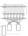
本実施形態では、立体映像表示装置1Dは、時間分割を行わずに、2台のプロジェクタ101,102が同時に投影を行う。図11に示すように、立体映像表示装置1Dは、プロジェクタ101,102と、コリメータレンズ20と、レンズアレイ30と、空間光変調素子40と、制御装置50Dとを備える。
In the present embodiment, the stereoscopic image display device 1D is without time division, two
プロジェクタ101,102は、異なる位置(例えば、上下)に配置されている。また、プロジェクタ101,102は、制御装置50Dからの制御に従って、点光源群形成用パターン601,602の投影方向を変更する。例えば、プロジェクタ101,102は、一般的なレンズシフト機能により、点光源群形成用パターン601,602の投影方向を変更できる。
The
図11では、プロジェクタ101が、図12(a)の点光源群形成用パターン601をレンズアレイ30に投影する。ここでは、プロジェクタ101が、上から数えて奇数番目の要素レンズ31に対し、斜め方向から点光源形成用パターン611Wを投影する。これにより、視域V1が、奇数番目の要素レンズ31において、光軸から下端まで形成されている。
In Figure 11, the
また、プロジェクタ102が、図12(b)の点光源群形成用パターン602をレンズアレイ30に投影する。ここでは、プロジェクタ102が、偶数番目の要素レンズ31に対し、斜め方向から点光源形成用パターン612Wを投影する。これにより、視域V2が、偶数番目の要素レンズ31において、光軸から上端まで形成されている。
The
本実施形態では、プロジェクタ101,102が投影した点光源形成用パターン611W,612Wにより、同一位置に点光源pが形成され、2つの視域V1,V2が連続することになる。従って、空間光変調素子40は、連続する視域V1,V2に対応した位置に、要素画像eで構成される要素画像群Eを表示する。
In the present embodiment, the point light source p is formed at the same position by the point light
<制御装置>
以下、制御装置50Dを詳細に説明する。
制御装置50Dは、プロジェクタ101,102が投影する点光源群形成用パターン601,602により、同一位置に点光源pを形成し、かつ、プロジェクタ101,102が表示する立体映像の視域V1,V2が連続するように、非マスク領域631,632の位置及び投影方向を設定するものである。
<Control device>
Hereinafter, the
本実施形態では、制御装置50Dは、投影間隔=‘2’に設定する。そして、制御装置50Dは、図12(a)に示すように、非マスク領域631の大きさaがD・f/Lとなるように、点光源形成用パターン611Wの中央から下側まで非マスク領域631を設定する。
In the present embodiment, the
また、制御装置50Dは、図12(a)に示すように、投影間隔に従って、非マスク領域631が含まれる点光源形成用パターン611Wと、全面がマスク領域65の点光源形成用パターン61Bとを設定する。ここで、制御装置50Dは、点光源形成用パターン611Wを偶数番目に設定し、点光源形成用パターン61Bを奇数番目に設定する。
Further, the
また、制御装置50Dは、図12(b)に示すように、図12(a)と同一サイズの非マスク領域632を点光源形成用パターン612Wの上側から中央まで設定する。ここで、例えば、制御装置50Dは、点光源形成用パターン612Wを奇数番目に設定し、点光源形成用パターン61Bを偶数番目に設定する。
The
そして、制御装置50Dは、点光源pが各要素レンズ31の光軸からD/2の位置に形成されるように、各要素レンズ31の光軸に対して斜め上から下記の式(6)で表される角度σで、点光源群形成用パターン601を投影することをプロジェクタ101に指令する。
Then, the
![]()
![]()
さらに、制御装置50Dは、各要素レンズ31の光軸に対して斜め下から式(6)の角度σで、点光源群形成用パターン602を投影することをプロジェクタ102に指令する。その後、制御装置50Dは、要素画像群Eの表示を空間光変調素子40に指令する。
Further, the
[作用・効果]
以上のように、立体映像表示装置1Dは、2台のプロジェクタ101,102による視域V1,V2を連続的に繋げることで、レンズアレイ30の制限を超えて、立体映像の視域角を拡大することができる。
[Action / Effect]
As described above, the stereoscopic image display device 1D exceeds the limitation of the
(第5実施形態)
[立体映像表示装置]
図13,図14を参照し、本発明の第5実施形態に係る立体映像表示装置1Eについて、第4実施形態と異なる点を説明する。立体映像表示装置1Eは、1個の要素レンズ31で2個の点光源pを形成する点が、第4実施形態と異なる。
(Fifth Embodiment)
[Stereoscopic image display device]
With reference to FIGS. 13 and 14, the stereoscopic image display device 1E according to the fifth embodiment of the present invention will be described as different from the fourth embodiment. The stereoscopic image display device 1E differs from the fourth embodiment in that two point light sources p are formed by one
本実施形態では、立体映像表示装置1Eは、時間分割を行わずに、2台のプロジェクタ101,102が同時に投影を行う。図13に示すように、立体映像表示装置1Eは、プロジェクタ101,102と、コリメータレンズ20と、レンズアレイ30と、空間光変調素子40と、制御装置50Eとを備える。
In the present embodiment, the stereoscopic image display device 1E are without time division, two
図13では、プロジェクタ101が、図14(a)の点光源群形成用パターン601を斜め上から各要素レンズ31の下側に投影する。これにより、視域V1が、各要素レンズ31の下側に形成されている。
また、プロジェクタ102が、図14(b)の点光源群形成用パターン602を斜め下から各要素レンズ31の上側に投影する。これにより、視域V2が、各要素レンズ31の上側に形成されている。
このように、立体映像表示装置1Eは、1個の要素レンズ31で2個の点光源pを形成する。
In Figure 13, the
The
In this way, the stereoscopic image display device 1E forms two point light sources p with one
<制御装置>
以下、制御装置50Eを詳細に説明する。
制御装置50Eは、プロジェクタ101,102が投影する点光源群形成用パターン601,602により、プロジェクタ101,102毎の位置に点光源pを形成するように、非マスク領域63の位置及び投影方向を設定するものである。
<Control device>
Hereinafter, the
具体的には、制御装置50Eは、図14(a)に示すように、非マスク領域631の大きさaがD・f/(2・L)となるように、点光源形成用パターン611の下側に非マスク領域631を設定する。ここでは、制御装置50Eは、全ての点光源形成用パターン611に非マスク領域631を設定する。
Specifically, the
また、制御装置50Eは、図14(b)に示すように、図14(a)と同一サイズの非マスク領域632を点光源形成用パターン612の上側に設定する。ここで、制御装置50Eは、全ての点光源形成用パターン612に非マスク領域632を設定する。
Further, the
そして、制御装置50Eは、点光源pが各要素レンズ31の光軸からD/4の位置に形成されるように、各要素レンズ31の下側に斜め上から下記の式(7)で表される角度σで、点光源群形成用パターン601を投影することをプロジェクタ101に指令する。
Then, the
![]()
![]()
さらに、制御装置50Eは、各要素レンズ31の上側に斜め下から式(7)で表される角度σで、点光源群形成用パターン602を投影することをプロジェクタ102に指令する。その後、制御装置50Dは、要素画像群Eの表示を空間光変調素子40に指令する。
Furthermore, the
[作用・効果]
以上のように、立体映像表示装置1Eは、1個の要素レンズ31で2個の点光源p1,p2を形成することで点光源pの数を増加させ、レンズアレイ30の制限を超えて立体映像の解像度を向上させることができる。
[Action / Effect]
As described above, the stereoscopic image display device 1E increases the number of point light sources p by forming one
(第6実施形態)
[立体映像表示装置]
図15,図16を参照し、本発明の第6実施形態に係る立体映像表示装置1Fについて、第5実施形態と異なる点を説明する。立体映像表示装置1Fは、2台のプロジェクタ101,102で立体映像を時間分割表示する点が、第5実施形態と異なる。
(Sixth Embodiment)
[Stereoscopic image display device]
With reference to FIGS. 15 and 16, the stereoscopic
本実施形態では、立体映像表示装置1Fは、図15(a)及び図15(b)の状態を短時間で切り替える(時間分割回数=2)。図15に示すように、立体映像表示装置1Fは、プロジェクタ101,102と、コリメータレンズ20と、レンズアレイ30と、空間光変調素子40と、制御装置50Fとを備える。
In the present embodiment, the stereoscopic
図15(a)の状態では、プロジェクタ101が、図16(a)の点光源群形成用パターン601を斜め上からレンズアレイ30に投影する。これにより、点光源p1及び視域V1が、要素レンズ31の下側に形成されている。従って、空間光変調素子40は、視域V1に対応した要素画像e1で構成される要素画像群E1を表示する。
Figure in the state of 15 (a), the
図15(b)の状態では、プロジェクタ102が、図16(b)の点光源群形成用パターン602を斜め下からレンズアレイ30に投影する。これにより、点光源p2及び視域V2が、要素レンズ31の上側に形成されている。従って、空間光変調素子40は、視域V2に対応した要素画像e2で構成される要素画像群E2を表示する。
In the state of FIG. 15 (b), the
つまり、図15(a)及び図15(b)の状態では、プロジェクタ101,102が投影した点光源群形成用パターン601,602により、投射角度に応じて異なる位置に点光源p1,p2が形成されることになる。このように、立体映像表示装置1Fは、1個の要素レンズ31が2個の点光源p1,p2を形成する。
That is, in the state shown in FIG. 15 (a) and FIG. 15 (b), the
<制御装置>
以下、制御装置50Fを詳細に説明する。
制御装置50Fは、プロジェクタ101,102が投影する点光源群形成用パターン601,602により、プロジェクタ101,102毎の位置に点光源p1,p2を形成するように、投影方向を時間分割で切り替えるものである。
<Control device>
Hereinafter, the
具体的には、制御装置50Fは、図16(a)に示すように、非マスク領域63の大きさaがD・f/Lとなるように、点光源形成用パターン611の中央に非マスク領域63を設定する。ここで、制御装置50Fは、全ての点光源形成用パターン611に非マスク領域63を設定する。
Specifically, the
また、制御装置50Fは、図16(b)に示すように、図16(a)と同一の点光源形成用パターン612を設定する。つまり、点光源群形成用パターン601,602は、同一のものである。
The
図15(a)では、制御装置50Fは、各要素レンズ31に斜め上から、点光源群形成用パターン601を投影することをプロジェクタ101に指令する。さらに、制御装置50Fは、点光源群形成用パターン601の投影に同期して、要素画像群E1の表示を空間光変調素子40に指令する。
Figure 15 (a), the
図15(b)では、制御装置50Fは、各要素レンズ31に斜め下から、点光源群形成用パターン602を投影することをプロジェクタ102に指令する。さらに、制御装置50Fは、点光源群形成用パターン602の投影に同期して、要素画像群E2の表示を空間光変調素子40に指令する。
Figure 15 (b), the
<点光源形成用パターンの光強度分布>
本実施形態では、図17に示すように、視域V1,V2が重なる領域(ハッチングで図示)の立体映像が、視域V1,V2が重ならない領域の立体映像よりも明るくなってしまう。そこで、点光源形成用パターン61に光強度分布を設定し、視域V1,V2の明るさを均一にすることが好ましい。
<Light intensity distribution of point light source formation pattern>
In the present embodiment, as shown in FIG. 17, the stereoscopic image of the region where the visual regions V 1 and V 2 overlap (shown by hatching) becomes brighter than the stereoscopic image of the region where the visual regions V 1 and V 2 do not overlap. It ends up. Therefore, to set the light intensity distribution to a point light
すなわち、制御装置50Fは、視域V1,V2が重なる領域が暗くなるように、点光源形成用パターン611,612に光強度分布67を設定する。具体的には、制御装置50Fは、図18(a)に示すように、点光源形成用パターン611の非マスク領域63の下側が暗くなるような光強度分布67を設定する。さらに、制御装置50Fは、図18(b)に示すように、点光源形成用パターン612の非マスク領域63の上側が暗くなるような光強度分布67を設定する。
That is, the
[作用・効果]
以上のように、立体映像表示装置1Bは、図15(a)及び図15(b)の状態を短時間で切り替えるので、点光源pの数を増やして立体映像の解像度を向上させたり、視域角を拡大させたりして、立体映像の品質を向上することができる。
さらに、立体映像表示装置1Bは、2つの視域V1,V2の明るさを均一にできるので、立体映像の品質を向上させた状態で維持することができる。
[Action / Effect]
As described above, since the stereoscopic
Further, the stereoscopic
(第7実施形態)
[立体映像表示装置]
図19を参照し、本発明の第7実施形態に係る立体映像表示装置1Gについて、第1実施形態と異なる点を説明する。立体映像表示装置1Gは、表示特性が異なる立体映像を表示する点が、第1実施形態と異なる。
(7th Embodiment)
[Stereoscopic image display device]
With reference to FIG. 19, the stereoscopic image display device 1G according to the seventh embodiment of the present invention will be described as different from the first embodiment. The stereoscopic image display device 1G is different from the first embodiment in that it displays a stereoscopic image having different display characteristics.
図19(a)に示すように、立体映像表示装置1Gは、視域角が広い立体映像を上側に表示し、解像度が高い立体映像を下側に表示するものである。立体映像表示装置1Gは、プロジェクタ10と、コリメータレンズ20と、レンズアレイ30と、空間光変調素子40と、制御装置50Gとを備える。
As shown in FIG. 19A, the stereoscopic image display device 1G displays a stereoscopic image having a wide viewing angle on the upper side and a stereoscopic image having a high resolution on the lower side. The stereoscopic image display device 1G includes a
制御装置50Gは、上側で立体映像の視域角が広く、下側で立体映像の解像度が高くなるようにプロジェクタ10を制御するものである。例えば、制御装置50Gは、図19(b)に示すように、立体映像表示装置1Gの上側について、非マスク領域63を大きくし、点光源形成用パターン61の投影間隔を‘2’に設定する(図6参照)。立体映像表示装置1Gの下について、制御装置50Gは、非マスク領域63を小さくし、点光源形成用パターン61の投影間隔を‘1’に設定する(図5参照)。
The
[作用・効果]
以上のように、立体映像表示装置1Gは、異なる表示特性を組み合わせることで、立体映像コンテンツの内容、立体映像の観察者の視聴位置、表示環境といった様々な要因を考慮して、立体映像を表示することができる。
[Action / Effect]
As described above, the stereoscopic image display device 1G displays a stereoscopic image by combining different display characteristics in consideration of various factors such as the content of the stereoscopic image content, the viewing position of the observer of the stereoscopic image, and the display environment. can do.
なお、立体映像表示装置1Gは、第2実施形態以降で説明した時間分割表示やプロジェクタ10の複数台表示を組み合わせることもできる。この場合、立体映像表示装置1Gは、点光源pの数を増やして立体映像の解像度をさらに向上させたり、立体映像の視域角をさらに拡大することができる。
The stereoscopic image display device 1G can also combine the time division display and the display of a plurality of
(第8実施形態)
[立体映像表示装置]
図20〜図22を参照し、本発明の第8実施形態に係る立体映像表示装置1Hの構成を説明する。
(8th Embodiment)
[Stereoscopic image display device]
The configuration of the stereoscopic
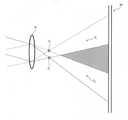
図20に示すように、立体映像表示装置1Hは、小型化を図ったものであり、プロジェクタ10Hと、平行光出射手段としてのコリメータレンズ20H及びミラー21と、レンズアレイ30と、空間光変調素子40と、制御装置50とを備える。
As shown in FIG. 20, the stereoscopic
プロジェクタ10Hは、レンズアレイ30の光軸方向から外れて位置するものである。本実施形態では、プロジェクタ10Hは、立体映像表示装置1Hの下側台座部に配置されている。そして、プロジェクタ10Hは、立体映像表示装置1Hの後方に位置するミラー21に点光源群形成用パターン60を投影する。
The
ミラー21は、プロジェクタ10Hが投影した点光源群形成用パターン60を、立体映像表示装置1Hの前方に位置するコリメータレンズ20H及びレンズアレイ30に向けて反射するものである。例えば、ミラー21は、一般的な光学反射鏡である。
The
コリメータレンズ20Hは、ミラー21で反射された点光源群形成用パターン60を平行光として、レンズアレイ30に出射するものである。他の点、コリメータレンズ20Hは、図1のコリメータレンズ20と同様である。
The
ここで、立体映像表示装置1Hは、図21に示すように、コリメータレンズ20H及びミラー21を凹面ミラー(平行光出射手段)25で代用することもできる。
凹面ミラー25は、プロジェクタ10Hが投影した点光源群形成用パターン60を、平行光としてレンズアレイ30に向けて反射するものである。
Here, as shown in FIG. 21, the stereoscopic
The
さらに、立体映像表示装置1Hは、図22に示すように、小型のプロジェクタ101,102,…,10nと、各プロジェクタ10に対応したコリメータレンズ201,202,…,20nとを近接配置してもよい(但し、nは2以上の整数)。
Further, the stereoscopic
[作用・効果]
以上のように、立体映像表示装置1Hは、ミラー21又は凹面ミラー25を用いることで、プロジェクタ10Hを立体映像表示装置1Hの下側台座部に配置可能となり、立体映像表示装置1Hを薄くし、小型化を図ることができる。
さらに、立体映像表示装置1Hは、小型のプロジェクタ10及びコリメータレンズ20を近接配置することで、立体映像表示装置1Hを薄くし、小型化を図ることができる。
[Action / Effect]
As described above, by using the
Further, the stereoscopic
以上、本発明の各実施形態を詳述してきたが、本発明は前記した実施形態に限られるものではなく、本発明の要旨を逸脱しない範囲の設計変更等も含まれる。
前記した各実施形態では、非マスク領域を正方形としたが、本発明は、これに限定されない。つまり、本発明では、要素レンズの形状等に応じて、非マスク領域を長方形等の形状としてもよい。
Although each embodiment of the present invention has been described in detail above, the present invention is not limited to the above-described embodiment, and includes design changes and the like within a range not deviating from the gist of the present invention.
In each of the above-described embodiments, the non-masked region is square, but the present invention is not limited thereto. That is, in the present invention, the non-masked region may have a rectangular shape or the like depending on the shape of the element lens or the like.
前記した第4,5,6実施形態では、2台のプロジェクタを用いることとして説明したが、本発明は、これに限定されない。つまり、本発明では、2台以上のプロジェクタを用いることができる。 Although the above-described fourth, fifth, and sixth embodiments have been described as using two projectors, the present invention is not limited thereto. That is, in the present invention, two or more projectors can be used.
以下、図23,図24を参照し、本発明の実施例を説明する。
図23に示すように、実施例に係る立体映像表示装置1は、第1実施形態と同様の構成とする。なお、図23(b)及び図23(c)では、立体映像表示装置1の一部の図示を省略した。
Hereinafter, examples of the present invention will be described with reference to FIGS. 23 and 24.
As shown in FIG. 23, the stereoscopic image display device 1 according to the embodiment has the same configuration as that of the first embodiment. In addition, in FIG. 23B and FIG. 23C, a part of the stereoscopic image display device 1 is not shown.
以下、立体映像表示装置1のパラメータを列挙する。
立体映像表示装置1では、画面サイズが500mm、最大視域角が40°、観視距離が1.5mである。
プロジェクタ10は、投影サイズが500mmである。
コリメータレンズ20は、直径が500mm、焦点距離Fが800mmである。また、各平行光の投影幅αが、図23(a)では0.14mm、図23(b)では0.28mm、図23(c)では0.42mmである。
The parameters of the stereoscopic image display device 1 are listed below.
In the stereoscopic image display device 1, the screen size is 500 mm, the maximum viewing area angle is 40 °, and the viewing distance is 1.5 m.
The
The
レンズアレイ30は、1189個の要素レンズ31を備え、レンズピッチが0.42mm、要素レンズ31の焦点距離fが0.58mmである。
空間光変調素子40は、大きさが500mmである。また、空間光変調素子40とレンズアレイ30との距離は、焦点距離fの4倍=2.32mmである。
The
The spatial
立体映像表示装置1は、図23(a)〜(c)に示すように、立体映像の解像度と視域角とのバランスを3段階で調整(変更)できる。 As shown in FIGS. 23 (a) to 23 (c), the stereoscopic image display device 1 can adjust (change) the balance between the resolution of the stereoscopic image and the viewing area angle in three stages.
図23(a)の状態では、立体映像表示装置1が、図24(a)の点光源群形成用パターン60を投影することで、立体映像の解像度が最大となる一方、最大視域角が14°と最も狭くなる。
図23(b)の状態では、立体映像表示装置1が、図24(b)の点光源群形成用パターン60を投影することで、立体映像の解像度と視域角が中間段階となり、最大視域角が27°となる。
図23(c)の状態では、立体映像表示装置1が、図24(c)の点光源群形成用パターン60を投影することで、最大視域角が40°となり、立体映像の視域角が最も広くなる一方、立体映像の解像度が最低となる。
In the state of FIG. 23 (a), the stereoscopic image display device 1 projects the
In the state of FIG. 23 (b), the stereoscopic image display device 1 projects the
In the state of FIG. 23 (c), the stereoscopic image display device 1 projects the point light source
ここで、立体映像表示装置1では、調整の自由度を向上させる場合、空間光変調素子40をレンズアレイ30から離す、又は、要素レンズ31の焦点距離fを短くすればよい。何れの場合も、立体映像表示装置1では、空間光変調素子40を焦点距離fのN倍の位置に配置することで、立体映像の解像度と視域角のバランスをN−1段階で調整できる。
Here, in the stereoscopic image display device 1, in order to improve the degree of freedom of adjustment, the spatial
なお、空間光変調素子40をレンズアレイ30から離す程、点光源群形成用パターン60の精緻な投影が要求されることになる。従って、空間光変調素子40の位置は、プロジェクタ10の解像度や投影精度も考慮して決定することが好ましい。
The farther the spatial
1〜1H 立体映像表示装置1
10,101,102,10H プロジェクタ(投影手段)
20,20H コリメータレンズ(平行光出射手段)
21 ミラー(平行光出射手段)
30 レンズアレイ
31 要素レンズ
40 空間光変調素子
50〜50G 制御装置(制御手段)
1-1H stereoscopic image display device 1
10 , 10 1 , 10 2 , 10H projector (projection means)
20,20H collimator lens (parallel light emitting means)
21 Mirror (parallel light emitting means)
30
Claims (9)
点光源の配光特性を表すマスク画像が要素レンズに対応して配列された点光源群形成用パターンを投影する投影手段と、
前記投影手段が投影した点光源群形成用パターンを平行光として出射する平行光出射手段と、
前記要素レンズが2次元状に配列され、前記平行光出射手段からの平行光を各要素レンズの焦点に集光することで、前記点光源群を形成するレンズアレイと、
要素画像群を表示する空間光変調素子と、
前記マスク画像に含まれる非マスク領域の位置及び大きさと、前記非マスク領域の光強度分布と、前記非マスク領域が含まれるマスク画像の投影間隔と、前記マスク画像の投影方向との何れか1以上を制御する制御手段と、を備え、
前記マスク画像の全部又は一部は、前記投影手段が最大輝度の光を投影する矩形状の前記非マスク領域と、前記非マスク領域の周囲に位置し、前記投影手段が光を投影しない矩形状の外形のマスク領域とを有することを特徴とする立体映像表示装置。 It is an integral photography type stereoscopic image display device that displays a stereoscopic image using a point light source group as a backlight.
A projection means for projecting a light source group forming patterns that mask image image are arranged in correspondence with the element lenses representing the light distribution characteristics of the point light source,
A parallel light emitting means that emits a pattern for forming a point light source group projected by the projection means as parallel light, and a parallel light emitting means.
A lens array in which the element lenses are arranged in a two-dimensional shape and the parallel light from the parallel light emitting means is focused on the focal point of each element lens to form the point light source group.
Spatial light modulation elements that display element images and
The position and size of the non-masked regions included in the mask image, and the light intensity distribution of the non-masked region, the projection distance of the mask image including the non-masked area, or the projection direction of the mask image 1 With a control means for controlling the above ,
All or part of the mask image is a rectangular non-masked region on which the projection means projects the maximum brightness light and a rectangular shape that is located around the non-masked region and the projection means does not project light. A stereoscopic image display device characterized by having a mask area of the outer shape of the above.
前記立体映像の解像度を高くする場合、前記非マスク領域を小さく、かつ、前記非マスク領域が含まれるマスク画像の投影間隔を短くし、
前記立体映像の視域角を広くする場合、前記非マスク領域を大きく、かつ、前記非マスク領域が含まれるマスク画像の投影間隔を長くすることを特徴とする請求項1に記載の立体映像表示装置。 The control means is one.
When increasing the resolution of the stereoscopic image, the non-masked area is made small, and the projection interval of the masked image including the non-masked area is shortened.
The stereoscopic image display according to claim 1, wherein when the viewing area angle of the stereoscopic image is widened, the non-masked area is enlarged and the projection interval of the mask image including the non-masked area is lengthened. apparatus.
前記制御手段は、時間分割で表示される前記立体映像の視域毎に、当該視域に対応した位置及び大きさの前記非マスク領域を設定し、設定した前記非マスク領域が含まれるマスク画像を時間分割で切り替えることを特徴とする請求項1に記載の立体映像表示装置。 The projection means is one.
The control means sets the non-masked area of a position and size corresponding to the visual field for each visual field of the stereoscopic image displayed by time division, and a mask image including the set non-masked area. The stereoscopic image display device according to claim 1, wherein the three-dimensional image display device is switched by time division.
前記制御手段は、前記非マスク領域が含まれるマスク画像の投影間隔を任意の長さに設定し、前記非マスク領域が含まれるマスク画像と、前記非マスク領域が含まれないマスク画像とを時間分割で切り替えることを特徴とする請求項1に記載の立体映像表示装置。 The projection means is one.
The control means, the projection distance of the mask image including the said unmasked region set to any length, wherein the mask image including the non-masked area, said mask image does not include the non-masked area Time The stereoscopic image display device according to claim 1, wherein the image is switched by division.
前記制御手段は、各投影手段が投影する前記点光源群形成用パターンにより、同一位置に前記点光源を形成し、かつ、前記各投影手段が表示する立体映像の視域が連続するように、前記非マスク領域の位置及び前記投影方向を設定することを特徴とする請求項1に記載の立体映像表示装置。 There are two or more projection means,
The control means forms the point light source at the same position by the pattern for forming the point light source group projected by each projection means, and the viewing range of the stereoscopic image displayed by each projection means is continuous. The stereoscopic image display device according to claim 1, wherein the position of the non-masked region and the projection direction are set.
前記制御手段は、各投影手段が投影する前記点光源群形成用パターンにより、前記投影手段毎の位置に前記点光源を形成するように、前記非マスク領域の位置及び前記投影方向を設定することを特徴とする請求項1に記載の立体映像表示装置。 The number of the projection means is two or more, and the control means is the non-masked region so that the point light source is formed at the position of each projection means by the pattern for forming the point light source group projected by each projection means. The stereoscopic image display device according to claim 1, wherein the position of the above and the projection direction are set.
前記制御手段は、各投影手段が投影する前記点光源群形成用パターンにより、前記投影手段毎の位置に前記点光源を形成するように、前記投影方向を時間分割で切り替えることを特徴とする請求項1に記載の立体映像表示装置。 The number of the projection means is two or more, and the control means sets the projection direction so as to form the point light source at the position of each projection means by the pattern for forming the point light source group projected by each projection means. The stereoscopic image display device according to claim 1, wherein the three-dimensional image display device is switched by time division.
前記平行光出射手段は、
前記投影手段が投影した点光源群形成用パターンを前記レンズアレイに向けて反射するミラーと、前記ミラーで反射された点光源群形成用パターンを平行光として出射するコリメータレンズとを備えるか、又は、
前記投影手段が投影した点光源群形成用パターンを平行光として前記レンズアレイに向けて反射する凹面ミラーを備えることを特徴とする請求項1から請求項8の何れか一項に記載の立体映像表示装置。 The projection means is located off the optical axis direction of the lens array.
The parallel light emitting means
It is provided with a mirror that reflects the point light source group forming pattern projected by the projection means toward the lens array, and a collimator lens that emits the point light source group forming pattern reflected by the mirror as parallel light. ,
The stereoscopic image according to any one of claims 1 to 8, further comprising a concave mirror that reflects the point light source group forming pattern projected by the projection means as parallel light toward the lens array. Display device.
Priority Applications (1)
| Application Number | Priority Date | Filing Date | Title |
|---|---|---|---|
| JP2017060647A JP6899237B2 (en) | 2017-03-27 | 2017-03-27 | Stereoscopic image display device |
Applications Claiming Priority (1)
| Application Number | Priority Date | Filing Date | Title |
|---|---|---|---|
| JP2017060647A JP6899237B2 (en) | 2017-03-27 | 2017-03-27 | Stereoscopic image display device |
Publications (2)
| Publication Number | Publication Date |
|---|---|
| JP2018163282A JP2018163282A (en) | 2018-10-18 |
| JP6899237B2 true JP6899237B2 (en) | 2021-07-07 |
Family
ID=63860482
Family Applications (1)
| Application Number | Title | Priority Date | Filing Date |
|---|---|---|---|
| JP2017060647A Active JP6899237B2 (en) | 2017-03-27 | 2017-03-27 | Stereoscopic image display device |
Country Status (1)
| Country | Link |
|---|---|
| JP (1) | JP6899237B2 (en) |
Families Citing this family (2)
| Publication number | Priority date | Publication date | Assignee | Title |
|---|---|---|---|---|
| JP7240977B2 (en) * | 2019-07-10 | 2023-03-16 | 日本放送協会 | image display device |
| CN111736362A (en) * | 2020-07-29 | 2020-10-02 | 中国人民解放军陆军装甲兵学院 | Integrated imaging three-dimensional display system |
Family Cites Families (5)
| Publication number | Priority date | Publication date | Assignee | Title |
|---|---|---|---|---|
| JP2627032B2 (en) * | 1991-06-19 | 1997-07-02 | ソニー・テクトロニクス株式会社 | Liquid crystal cell type video projector |
| KR101170797B1 (en) * | 2005-07-26 | 2012-08-02 | 삼성전자주식회사 | 3D image display using integral imaging technology |
| JP2008052010A (en) * | 2006-08-24 | 2008-03-06 | Noriji Ooishi | Stereoscopic image display device and photographing device |
| JP2010127973A (en) * | 2008-11-25 | 2010-06-10 | Toshiba Corp | Stereoscopic image display |
| JP2014102274A (en) * | 2012-11-16 | 2014-06-05 | Nikon Corp | Display device |
-
2017
- 2017-03-27 JP JP2017060647A patent/JP6899237B2/en active Active
Also Published As
| Publication number | Publication date |
|---|---|
| JP2018163282A (en) | 2018-10-18 |
Similar Documents
| Publication | Publication Date | Title |
|---|---|---|
| US9081196B2 (en) | Display apparatus | |
| KR100864139B1 (en) | Method and apparatus for displaying 3d images | |
| US7327410B2 (en) | High resolution 3-D image display with liquid crystal shutter array | |
| US10609362B2 (en) | Projected hogel autostereoscopic display | |
| CN106873299A (en) | Scanning projector transmissive viewing screen and scanning projection instrument system | |
| US8212198B2 (en) | Laser projection device having a diffuser arranged in an image focal plane and an object focal plane and method for manufacturing a laser projection device | |
| US10750101B2 (en) | Resolution for autostereoscopic video displays | |
| EP4194929A1 (en) | One-way homogeneous beam expanding screen and three-dimensional display device | |
| JPH11352613A (en) | Image recorder and image reproducing device | |
| JP6899237B2 (en) | Stereoscopic image display device | |
| US20040125345A1 (en) | Projection display apparatus with a curved screen | |
| JP2002228974A (en) | Stereoscopic image display device | |
| US20080259281A1 (en) | Apparatus and method for displaying three-dimensional image | |
| Kikuta et al. | Development of SVGA resolution 128-directional display | |
| JP2015225218A (en) | Image display device | |
| JP2010122646A (en) | Screen and image display device | |
| CN106255915A (en) | Rear projection screen and head up displays | |
| JP2015184619A (en) | projector | |
| EP0691790A2 (en) | Image display apparatus | |
| EP2290993A1 (en) | Lens system for three-dimensional display applications | |
| JP7424786B2 (en) | 3D image display device, 3D image display method, and 3D image generation and display system | |
| JP6714347B2 (en) | Stereoscopic image display device | |
| KR20050010495A (en) | Projection display apparatus | |
| JPH06130378A (en) | Image display device | |
| JP2013213963A (en) | Naked eye three-dimensional view display and two-dimensional picture display device used for naked eye three-dimensional view display |
Legal Events
| Date | Code | Title | Description |
|---|---|---|---|
| A621 | Written request for application examination |
Free format text: JAPANESE INTERMEDIATE CODE: A621 Effective date: 20200130 |
|
| A977 | Report on retrieval |
Free format text: JAPANESE INTERMEDIATE CODE: A971007 Effective date: 20210129 |
|
| A131 | Notification of reasons for refusal |
Free format text: JAPANESE INTERMEDIATE CODE: A131 Effective date: 20210309 |
|
| A521 | Request for written amendment filed |
Free format text: JAPANESE INTERMEDIATE CODE: A523 Effective date: 20210426 |
|
| TRDD | Decision of grant or rejection written | ||
| A01 | Written decision to grant a patent or to grant a registration (utility model) |
Free format text: JAPANESE INTERMEDIATE CODE: A01 Effective date: 20210518 |
|
| A61 | First payment of annual fees (during grant procedure) |
Free format text: JAPANESE INTERMEDIATE CODE: A61 Effective date: 20210614 |
|
| R150 | Certificate of patent or registration of utility model |
Ref document number: 6899237 Country of ref document: JP Free format text: JAPANESE INTERMEDIATE CODE: R150 |
|
| R250 | Receipt of annual fees |
Free format text: JAPANESE INTERMEDIATE CODE: R250 |