JP6896183B2 - Lighting system for floodlight - Google Patents
Lighting system for floodlight Download PDFInfo
- Publication number
- JP6896183B2 JP6896183B2 JP2020541835A JP2020541835A JP6896183B2 JP 6896183 B2 JP6896183 B2 JP 6896183B2 JP 2020541835 A JP2020541835 A JP 2020541835A JP 2020541835 A JP2020541835 A JP 2020541835A JP 6896183 B2 JP6896183 B2 JP 6896183B2
- Authority
- JP
- Japan
- Prior art keywords
- lens
- optical system
- subgroup
- optical
- lenses
- Prior art date
- Legal status (The legal status is an assumption and is not a legal conclusion. Google has not performed a legal analysis and makes no representation as to the accuracy of the status listed.)
- Active
Links
Images


Classifications
-
- G—PHYSICS
- G02—OPTICS
- G02B—OPTICAL ELEMENTS, SYSTEMS OR APPARATUS
- G02B13/00—Optical objectives specially designed for the purposes specified below
- G02B13/16—Optical objectives specially designed for the purposes specified below for use in conjunction with image converters or intensifiers, or for use with projectors, e.g. objectives for projection TV
-
- G—PHYSICS
- G02—OPTICS
- G02B—OPTICAL ELEMENTS, SYSTEMS OR APPARATUS
- G02B19/00—Condensers, e.g. light collectors or similar non-imaging optics
- G02B19/0004—Condensers, e.g. light collectors or similar non-imaging optics characterised by the optical means employed
- G02B19/0028—Condensers, e.g. light collectors or similar non-imaging optics characterised by the optical means employed refractive and reflective surfaces, e.g. non-imaging catadioptric systems
-
- G—PHYSICS
- G02—OPTICS
- G02B—OPTICAL ELEMENTS, SYSTEMS OR APPARATUS
- G02B19/00—Condensers, e.g. light collectors or similar non-imaging optics
- G02B19/0033—Condensers, e.g. light collectors or similar non-imaging optics characterised by the use
- G02B19/0047—Condensers, e.g. light collectors or similar non-imaging optics characterised by the use for use with a light source
-
- G—PHYSICS
- G03—PHOTOGRAPHY; CINEMATOGRAPHY; ANALOGOUS TECHNIQUES USING WAVES OTHER THAN OPTICAL WAVES; ELECTROGRAPHY; HOLOGRAPHY
- G03B—APPARATUS OR ARRANGEMENTS FOR TAKING PHOTOGRAPHS OR FOR PROJECTING OR VIEWING THEM; APPARATUS OR ARRANGEMENTS EMPLOYING ANALOGOUS TECHNIQUES USING WAVES OTHER THAN OPTICAL WAVES; ACCESSORIES THEREFOR
- G03B21/00—Projectors or projection-type viewers; Accessories therefor
- G03B21/14—Details
- G03B21/20—Lamp housings
- G03B21/208—Homogenising, shaping of the illumination light
-
- G—PHYSICS
- G03—PHOTOGRAPHY; CINEMATOGRAPHY; ANALOGOUS TECHNIQUES USING WAVES OTHER THAN OPTICAL WAVES; ELECTROGRAPHY; HOLOGRAPHY
- G03B—APPARATUS OR ARRANGEMENTS FOR TAKING PHOTOGRAPHS OR FOR PROJECTING OR VIEWING THEM; APPARATUS OR ARRANGEMENTS EMPLOYING ANALOGOUS TECHNIQUES USING WAVES OTHER THAN OPTICAL WAVES; ACCESSORIES THEREFOR
- G03B21/00—Projectors or projection-type viewers; Accessories therefor
- G03B21/14—Details
- G03B21/28—Reflectors in projection beam
-
- G—PHYSICS
- G02—OPTICS
- G02B—OPTICAL ELEMENTS, SYSTEMS OR APPARATUS
- G02B26/00—Optical devices or arrangements for the control of light using movable or deformable optical elements
- G02B26/08—Optical devices or arrangements for the control of light using movable or deformable optical elements for controlling the direction of light
- G02B26/0816—Optical devices or arrangements for the control of light using movable or deformable optical elements for controlling the direction of light by means of one or more reflecting elements
- G02B26/0833—Optical devices or arrangements for the control of light using movable or deformable optical elements for controlling the direction of light by means of one or more reflecting elements the reflecting element being a micromechanical device, e.g. a MEMS mirror, DMD
-
- G—PHYSICS
- G03—PHOTOGRAPHY; CINEMATOGRAPHY; ANALOGOUS TECHNIQUES USING WAVES OTHER THAN OPTICAL WAVES; ELECTROGRAPHY; HOLOGRAPHY
- G03B—APPARATUS OR ARRANGEMENTS FOR TAKING PHOTOGRAPHS OR FOR PROJECTING OR VIEWING THEM; APPARATUS OR ARRANGEMENTS EMPLOYING ANALOGOUS TECHNIQUES USING WAVES OTHER THAN OPTICAL WAVES; ACCESSORIES THEREFOR
- G03B21/00—Projectors or projection-type viewers; Accessories therefor
- G03B21/005—Projectors using an electronic spatial light modulator but not peculiar thereto
- G03B21/008—Projectors using an electronic spatial light modulator but not peculiar thereto using micromirror devices
-
- G—PHYSICS
- G03—PHOTOGRAPHY; CINEMATOGRAPHY; ANALOGOUS TECHNIQUES USING WAVES OTHER THAN OPTICAL WAVES; ELECTROGRAPHY; HOLOGRAPHY
- G03B—APPARATUS OR ARRANGEMENTS FOR TAKING PHOTOGRAPHS OR FOR PROJECTING OR VIEWING THEM; APPARATUS OR ARRANGEMENTS EMPLOYING ANALOGOUS TECHNIQUES USING WAVES OTHER THAN OPTICAL WAVES; ACCESSORIES THEREFOR
- G03B21/00—Projectors or projection-type viewers; Accessories therefor
- G03B21/14—Details
- G03B21/20—Lamp housings
- G03B21/2066—Reflectors in illumination beam
Description
本発明による実施形態の1つ以上の態様は、照明源に関し、より詳細には、デジタルマイクロミラーデバイスへ光を送達するための光学システムに関する。 One or more aspects of the embodiments according to the invention relate to an illumination source, and more particularly to an optical system for delivering light to a digital micromirror device.
デジタルマイクロミラーデバイス(DMD)は、個々に電子的にアドレス指定することができる微小なマイクロミラーのアレイで構成されるマイクロ電気機械デバイスである。デジタルマイクロミラーデバイスは、投射システム(例えば、画像又はビデオを投影するため)において使用することができる。投射システムの照明システムは、光源と、光送達システムとを含んで良い。光源は、その出力平面において矩形の光源領域を有する光パイプであり、照射が実質的に一定である光パイプを含む。光送達システムは、光をデジタルマイクロミラーデバイスに伝搬しデジタルマイクロミラーデバイスの表面を実質的に均一に照明できる。矩形の光源領域のアスペクト比は、デジタルマイクロミラーデバイスのアスペクト比と同一にすることができる。 A digital micromirror device (DMD) is a microelectromechanical device composed of an array of microscopic micromirrors that can be individually and electronically addressed. Digital micromirror devices can be used in projection systems (eg, for projecting images or videos). The lighting system of the projection system may include a light source and an optical delivery system. The light source is an optical pipe having a rectangular light source region in its output plane and includes an optical pipe whose irradiation is substantially constant. The optical delivery system can propagate the light to the digital micromirror device and illuminate the surface of the digital micromirror device substantially uniformly. The aspect ratio of the rectangular light source area can be the same as the aspect ratio of the digital micromirror device.
マイクロミラーが作動される方法のために、デジタルマイクロミラーデバイスは、光源からの主光線に対してある角度で設置されてもよく、さらに、プリズムの第1の表面に設置されてもよい。プリズム内では、光源からデジタルマイクロミラーデバイスへと進む光は、プリズムの第2の表面から、全反射され、デジタルマイクロミラーデバイスへ向けられる。 Depending on how the micromirror is actuated, the digital micromirror device may be installed at an angle to the main ray from the light source and may be further installed on the first surface of the prism. Within the prism, the light traveling from the light source to the digital micromirror device is totally reflected from the second surface of the prism and directed to the digital micromirror device.
デジタルマイクロミラーデバイスと主光線との間の角度の効果、及びプリズムのウェッジは、システムに、光学システムの性能の劣化をもたらす可能性のある非対称性を導入する。性能劣化は、例えば、(i)矩形ではない歪んだ照明パッチ、及び(ii)照明パッチのエッジにおける鮮鋭度の損失をもたらす可能性のある不完全な焦点を生成する。そのような欠陥は、光学的効率の損失をもたらすことがある。例えば、いくつかの関連技術のシステムでは、光送達システムは、ただデジタルマイクロミラーデバイスの製造及びアセンブリの公差により必要とされるよりもかなり大きくデジタルマイクロミラーデバイスを過剰に満たす過大なサイズの照明パッチを生成するように設計することができる。それにより、照明パッチの不完全な矩形性又はそのエッジでのぼけにもかかわらず、デジタルマイクロミラーデバイスに亘る照明の均一性が許容され、上記不完全性によって影響される領域は、デジタルマイクロミラーデバイスのエッジから外れる。 The effect of the angle between the digital micromirror device and the principal ray, and the wedges of the prism, introduce into the system an asymmetry that can lead to poor performance of the optical system. Performance degradation produces, for example, (i) a distorted lighting patch that is not rectangular, and (ii) an incomplete focus that can result in a loss of sharpness at the edges of the lighting patch. Such defects can result in a loss of optical efficiency. For example, in some related technology systems, the optical delivery system is an oversized lighting patch that overfills the digital micromirror device, much larger than simply required by the manufacturing and assembly tolerances of the digital micromirror device. Can be designed to generate. Thereby, despite the imperfect rectangularity of the illumination patch or the blurring at its edges, the uniformity of illumination across the digital micromirror device is allowed, and the area affected by the imperfections is the digital micromirror. Off the edge of the device.
従って、デジタルマイクロミラーデバイスの照明システムで使用するための改良された光送達システムが必要とされている。 Therefore, there is a need for an improved optical delivery system for use in the lighting system of digital micromirror devices.
本開示の実施形態の態様は、光源からデジタルマイクロミラーデバイスへと光を送達するためのシステムに向けられる。システムは、1つ以上のレンズグループを含む。第1のレンズグループ内の少なくとも1つのレンズが、その光軸がシステムの主光線に同心しないように、横方向に変位される。 Aspects of the embodiments of the present disclosure are directed to a system for delivering light from a light source to a digital micromirror device. The system includes one or more lens groups. At least one lens in the first lens group is laterally displaced so that its optical axis is not concentric with the main rays of the system.
本発明の一実施形態によれば、光源の出力平面の光源領域から光を受け取り、空間変調した光を生成するための、主光線を有する光学システム(Fig.1)が提供される。前記光学システムは、第1の複数のレンズを含む第1のレンズグループ(グループ1)と;1つ以上のレンズを含む第2のレンズグループ(グループ2)と;を含み、前記第1のレンズグループの第1のレンズ(112)が:回転対称の前面と;回転対称の後面と;有効焦点距離と;前記回転対称の前面及び前記回転対称の後面によって定義される光軸と;を有し、前記前面と前記後面との間の前記光軸の部分の中間点が、前記第1のレンズの有効焦点距離の少なくとも5%だけ前記主光線からオフセットされている。 According to one embodiment of the present invention, there is provided an optical system (Fig. 1) having a main ray for receiving light from a light source region of the output plane of the light source and generating spatially modulated light. The optical system includes a first lens group (group 1) that includes a first plurality of lenses; and a second lens group (group 2) that includes one or more lenses; the first lens. The first lens (112) of the group has: a rotationally symmetric front surface; a rotationally symmetric posterior surface; an effective focal length; and an optical axis defined by the rotationally symmetric frontal surface and the rotationally symmetric rear surface; The midpoint of the portion of the optical axis between the front surface and the rear surface is offset from the main ray by at least 5% of the effective focal length of the first lens.
一実施形態では、前記第1のレンズグループは:第1のレンズサブグループ(グループ1a)と;第2のレンズサブグループ(グループ1b)と;を含み、前記第1のレンズサブグループは、前記第1のレンズ(112)及び第2のレンズ(111)を含み、前記第1のレンズ及び前記第2のレンズは、2mm未満だけ軸方向に離間されており、前記第2のレンズサブグループ(113, 114, 115)は、第3のレンズ及び第4のレンズを含み、前記第3のレンズ及び前記第4のレンズは2mm未満だけ軸方向に分離されている。 In one embodiment, the first lens group comprises: a first lens subgroup (group 1a); a second lens subgroup (group 1b); and the first lens subgroup is said. A first lens (112) and a second lens (111) are included, the first lens and the second lens are axially separated by less than 2 mm, and the second lens subgroup ( 113, 114, 115) includes a third lens and a fourth lens, the third lens and the fourth lens being axially separated by less than 2 mm.
一実施形態では、前記第1のレンズグループは、有効焦点距離を有し、当該光学システムは、前記第1のレンズグループと前記第2のレンズグループとの間に、前記第1のレンズグループの有効焦点距離の少なくとも1.4倍のギャップを含む。 In one embodiment, the first lens group has an effective focal length, and the optical system has a first lens group between the first lens group and the second lens group. Includes a gap of at least 1.4 times the effective focal length.
一実施形態では、前記光源領域の中間点から発生する光線が、前記ギャップ内において、
平行である、或いは半角が10度未満の集束円錐である。
In one embodiment, light rays generated from the midpoint of the light source region are emitted within the gap.
A focused cone that is parallel or has a half-width of less than 10 degrees.
一実施形態では、前記第2のレンズサブグループは、前記第3のレンズ及び前記第4のレンズを含む複数のレンズを有し、前記第2のレンズサブグループの前記複数のレンズ(113, 114, 115)の各レンズは、回転対称の前面と;回転対称の後面と;前記回転対称の前面及び前記回転対称の後面により定義される光軸と;を有し、前記第2のレンズサブグループの光軸の各々は、主光線に対して少なくとも2度だけ傾斜している。 In one embodiment, the second lens subgroup comprises a plurality of lenses including the third lens and the fourth lens, and the plurality of lenses (113, 114) of the second lens subgroup. Each lens of (115) has an anterior surface of rotational symmetry; a posterior surface of rotational symmetry; an optical axis defined by the anterior surface of the rotational symmetry and the posterior surface of the rotational symmetry; Each of the optical axes of is tilted at least 2 degrees with respect to the main ray.
一実施形態では、前記第2のレンズサブグループの前記レンズの前記光軸は、0.2度以内で互いに整合されている。 In one embodiment, the optical axes of the lenses in the second lens subgroup are aligned with each other within 0.2 degrees.
一実施形態では、前記第2のレンズサブグループの前記複数のレンズの、前記前面と前記後面との間の、前記光軸の前記部分の中間点は、前記主光線から大きくとも1mmだけオフセットされている。 In one embodiment, the midpoint of the portion of the optical axis between the front surface and the rear surface of the plurality of lenses in the second lens subgroup is offset by at most 1 mm from the main ray. ing.
一実施形態では、前記第2のレンズサブグループの前記複数のレンズ(113, 114, 115)の各光学軸の各々は、前記主光線に対して少なくとも2度だけ傾斜されている。 In one embodiment, each of the optic axes of the plurality of lenses (113, 114, 115) in the second lens subgroup is tilted by at least two degrees with respect to the principal ray.
一実施形態では、光学システムは、さらにプリズムを含み、前記プリズムは:第1の平坦表面と;第2の平坦表面と;第3の平坦表面と;を有し、前記プリズムは、第1の屈折率を有する透明材料で構成され、前記主光線が、前記第1の平坦表面を通してプリズムに入射し、前記プリズムの内部から前記第2の平坦表面の内部法線ベクトルに対して第1の角度で前記第2の平坦表面に当たり、前記第1の角度は、前記第1の屈折率の逆数の逆正弦関数よりも大きい。 In one embodiment, the optical system further comprises a prism, wherein the prism has: a first flat surface; a second flat surface; and a third flat surface; the prism is a first. Composed of a transparent material having a refractive index, the main ray enters the prism through the first flat surface, and a first angle from the inside of the prism with respect to the internal normal vector of the second flat surface. The first angle is larger than the inverse sine function of the inverse of the first refractive index.
一実施形態では、光学システムは、前記プリズムの前記第3の平坦表面に、かつそれに平行なデジタルマイクロミラーデバイスをさらに備え、前記主光線が、前記第2の平坦表面から反射され、前記第3の平坦表面を通って前記プリズムを出射し、前記デジタルマイクロミラーデバイスから反射され、前記第3の平坦表面を通して前記プリズムに再進入し、前記第2の平坦表面を通って前記プリズムを出射する。 In one embodiment, the optical system further comprises a digital micromirror device on and parallel to the third flat surface of the prism, the main ray being reflected from the second flat surface and said third. The prism exits through the flat surface of the device, is reflected from the digital micromirror device, re-enters the prism through the third flat surface, and exits the prism through the second flat surface.
一実施形態では、前記第1のレンズグループは:第1のレンズサブグループ(グループ1a)と;第2のレンズサブグループ(グループ1b)と;を含み、前記第1のレンズサブグループは、前記第1のレンズ(112)及び第2のレンズ(111)を含み、前記第1のレンズ及び前記第2のレンズは、2mm未満だけ軸方向に離間されており、前記第2のレンズサブグループ(113, 114, 115)は、第3のレンズ及び第4のレンズを含み、前記第3のレンズ及び前記第4のレンズは2mm未満だけ軸方向に分離されている。 In one embodiment, the first lens group comprises: a first lens subgroup (group 1a); a second lens subgroup (group 1b); and the first lens subgroup is said. A first lens (112) and a second lens (111) are included, the first lens and the second lens are axially separated by less than 2 mm, and the second lens subgroup ( 113, 114, 115) includes a third lens and a fourth lens, the third lens and the fourth lens being axially separated by less than 2 mm.
一実施形態では、前記第1のレンズグループは、有効焦点距離を有し、当該光学システムは、前記第1のレンズグループと前記第2のレンズグループとの間に、前記第1のレンズグループの有効焦点距離の少なくとも1.4倍のギャップを含む。 In one embodiment, the first lens group has an effective focal length, and the optical system has a first lens group between the first lens group and the second lens group. Includes a gap of at least 1.4 times the effective focal length.
一実施形態では、前記光源領域の中間点から発生する光線が、前記ギャップ内において、平行である、或いは半角が10度未満の集束円錐である。 In one embodiment, the light rays generated from the midpoint of the light source region are focused cones that are parallel or less than 10 degrees half-width within the gap.
一実施形態では、前記第2のレンズサブグループは、前記第3のレンズ及び前記第4のレンズを含む複数のレンズを有し、前記第2のレンズサブグループの前記複数のレンズ(113, 114, 115)の各レンズは、回転対称の前面と;回転対称の後面と;前記回転対称の前面及び前記回転対称の後面により定義される光軸と;を有し、前記第2のレンズサブグループの光軸の各々は、主光線に対して少なくとも2度だけ傾斜している。 In one embodiment, the second lens subgroup comprises a plurality of lenses including the third lens and the fourth lens, and the plurality of lenses (113, 114) of the second lens subgroup. Each lens of (115) has an anterior surface of rotational symmetry; a posterior surface of rotational symmetry; an optical axis defined by the anterior surface of the rotational symmetry and the posterior surface of the rotational symmetry; Each of the optical axes of is tilted at least 2 degrees with respect to the main ray.
一実施形態では、前記第2のレンズサブグループの前記レンズの前記光軸は、0.2度以内で互いに整合されている。 In one embodiment, the optical axes of the lenses in the second lens subgroup are aligned with each other within 0.2 degrees.
一実施形態では、前記第2のレンズサブグループの前記複数のレンズの、前記前面と前記後面との間の、前記光軸の前記部分の中間点は、前記主光線から大きくとも1mmだけオフセットされている。 In one embodiment, the midpoint of the portion of the optical axis between the front surface and the rear surface of the plurality of lenses in the second lens subgroup is offset by at most 1 mm from the main ray. ing.
一実施形態では、前記第2のレンズサブグループの前記第3のレンズ及び前記第4のレンズの各光学軸の各々は、前記主光線に対して少なくとも2度だけ傾斜されている。 In one embodiment, each of the optic axes of the third lens and the fourth lens of the second lens subgroup is tilted by at least two degrees with respect to the principal ray.
なお、特徴、態様、実施形態について、添付図面とともに以下に説明する。 The features, embodiments, and embodiments will be described below together with the accompanying drawings.
添付の図面に関連して以下に述べる詳細な説明は、本発明に従って提供される光投射のための照明システムの例示的な実施形態の説明を意図したものであり、本発明が構築又は利用され得る唯一の形態を表すことを意図したものではない。説明は、例示された実施形態に関連して、本発明の特徴を示す。しかしながら、本発明の精神及び範囲内に包含されることも意図される異なる実施形態によって、同一又は同等の機能及び構造が達成され得ることが理解されるべきである。本明細書の他の箇所で示されているように、同様の参照符号は、同様の要素又は特徴を示すことを意図している。 The detailed description described below in connection with the accompanying drawings is intended to illustrate exemplary embodiments of the lighting system for light projection provided in accordance with the present invention, wherein the invention is constructed or utilized. It is not intended to represent the only form of gain. The description shows the features of the invention in connection with the illustrated embodiments. However, it should be understood that the same or equivalent function and structure can be achieved by different embodiments that are also intended to be included within the spirit and scope of the invention. Similar reference numerals are intended to indicate similar elements or features, as shown elsewhere herein.
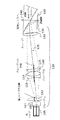
図1は、一実施形態における空間的に変調された光を生成するためのシステムを示す。光源が、出力平面106の矩形光源領域にわたって実質的に一定の照射を有する光を生成する。光送達システム120は、デジタルマイクロミラーデバイス110に光を送達する。デジタルマイクロミラーデバイスの各マイクロミラーから反射された光は、マイクロミラーがオン状態にあるかオフ状態にあるかに応じて、空間的に変調された光を生成するためにシステムの出力に送られるか、又は散逸される(例えば、ビームダンプに吸収される)かのいずれかである。マイクロミラーに印加された駆動電圧信号のパルス幅変調は、視聴者の目の応答能力を超える周波数で使用され、視聴者に中間程度の輝度の主観的印象を与える。
FIG. 1 shows a system for producing spatially modulated light in one embodiment. The light source produces light with a substantially constant illumination over the rectangular light source region of the
各ミラー又はピクセルは、「オン」状態及び「オフ」状態と称される2つの状態のうちの1つの状態にあるように制御可能である。DMDが通電されない場合には、マイクロミラーの表面がデジタルマイクロミラーデバイスの平面に整合する第3の「中立」状態もまた存在する(それにより、もしピクセルのすべてが中立位置にある場合には、ミラーのアレイを含むデジタルマイクロミラーデバイスの合成表面は、実質的に平面である)。オン状態では、マイクロミラーは、中立位置から角度A(例えば、角度Aは12度)だけ回転され、オフ状態では、マイクロミラーは、中立位置から角度Aだけ反対方向に回転される。それにより、オン状態からオフ状態に移行する際に、ミラーは、角度2Aだけ回転する。デジタルマイクロミラーデバイス表面へと向けられ、オン状態にあるピクセルにより反射された光は、投射レンズの瞳孔に入り、スクリーンに到達する。オフ状態のピクセルにより反射された光は、吸収ビームダンプへと向けられる。投射光学系の開口数(NA)はピクセル傾斜角によってNA=sin(A)として定義され、A = 12度の場合、対応するF数はf/ =0.5/NA = 2.41である。画像コントラストを改善するために、照明光学系は、わずかに高いF値、例えばf/ =2.45を有するように設計できる。 Each mirror or pixel can be controlled to be in one of two states, referred to as the "on" state and the "off" state. There is also a third "neutral" state in which the surface of the micromirror aligns with the plane of the digital micromirror device when the DMD is not energized (thus, if all of the pixels are in the neutral position). The synthetic surface of a digital micromirror device, including an array of mirrors, is substantially flat). In the on state, the micromirror is rotated from the neutral position by an angle A (eg, angle A is 12 degrees), and in the off state, the micromirror is rotated in the opposite direction by an angle A from the neutral position. As a result, the mirror rotates by an angle of 2A when transitioning from the on state to the off state. Light directed to the surface of the digital micromirror device and reflected by the on-state pixels enters the pupil of the projection lens and reaches the screen. The light reflected by the off-state pixels is directed to the absorption beam dump. The numerical aperture (NA) of the projection optics is defined by the pixel tilt angle as NA = sin (A), and for A = 12 degrees, the corresponding F number is f / = 0.5 / NA = 2.41. To improve image contrast, the illumination optics can be designed to have a slightly higher F-number, eg f / = 2.45.
高い光束効率のために、デジタルマイクロミラーデバイスは、投射光学系の開口数と等しい開口数を有する光によって一様に照明されてもよい。実際には、光束効率を犠牲にして画像コントラストを改善するために、照明光学系は投射光学系の開口数よりもわずかに小さい開口数を有することができる。また、高いスクリーン画像の均一性(80〜85%を超える)を達成するために、照明光がテレセントリック(telecentric)となるようにシステムを構成することができる。本明細書で使用される「テレセントリック性(Telecentricity)」とは、異なるマイクロミラーに当たる集束光円錐のそれぞれの主光線が互いに平行である程度を指す。 Due to the high luminous flux efficiency, the digital micromirror device may be uniformly illuminated by light having a numerical aperture equal to the numerical aperture of the projection optics. In practice, the illumination optics can have a numerical aperture slightly smaller than the numerical aperture of the projection optics in order to improve the image contrast at the expense of luminous flux efficiency. The system can also be configured so that the illumination light is telecentric in order to achieve high screen image uniformity (> 80-85%). As used herein, "telecentricity" refers to the extent to which the principal rays of the focused light cones that hit different micromirrors are parallel to each other.
いくつかの実施形態では、光源は、その放射照度が実質的に一定である矩形領域にわたって出力平面を有する。すなわち、光源は、その矩形領域内で実質的に空間的に均一な照射を生成する。光源は、本明細書で「ランプ」と称する不均一光源を含んでもよく、実質的に均一ではない照明を生成することができる。例えば、ランプはアークランプであってもよいし、1つ以上の発光ダイオードからなっていてもよい。この場合、光源は、さらに、一体ロッド(integrator rod)とも称され得る光パイプのような一体装置(integrating device)を含むことができる。光パイプは、矩形の断面を有する要素であってもよく、中実、又は内部表面に高反射性コーティングを有する中空であってもよい。光パイプの端部は、異なるサイズを有してもよく、出力端部は、デジタルマイクロミラーデバイスのアクティブ領域と同じアスペクト比を有してもよく、それにより、光パイプの出力端部は、リレーレンズ(relay lens)、又は「光送達システム(light delivery system)」を使用して、デジタルマイクロミラーデバイス上に都合よく再画像化され得る。 In some embodiments, the light source has an output plane over a rectangular region whose irradiance is substantially constant. That is, the light source produces a substantially spatially uniform irradiation within its rectangular region. The light source may include a non-uniform light source referred to herein as a "lamp" and can produce illumination that is not substantially uniform. For example, the lamp may be an arc lamp or may consist of one or more light emitting diodes. In this case, the light source can further include an integrating device, such as an optical pipe, which can also be referred to as an integrator rod. The optical pipe may be an element having a rectangular cross section, solid, or hollow with a highly reflective coating on the inner surface. The ends of the optical pipe may have different sizes and the output ends may have the same aspect ratio as the active region of the digital micromirror device, thereby causing the output ends of the optical pipe to have the same aspect ratio. It can be conveniently reimaged on a digital micromirror device using a relay lens, or "light delivery system".
図1は、一実施形態において、1024×768個のアクティブマイクロミラー(すなわち、「拡張グラフィックアレイ(Extended Graphics Array, XGA)」デバイス)、13.68ミクロンミラー(ピクセル)サイズ、及び12度のマイクロミラー傾斜角Aを有する、0.7インチデジタルマイクロミラーデバイス110のための照明システムの1つの図(任意に本明細書では側面図と称さする)を示す。デジタルマイクロミラーデバイスは、例えば、テキサス・インスツルメンツ(www.ti.com)から入手可能なDLP7000タイプ-Aデジタルマイクロミラーデバイスであってもよい。図1の実施形態では、光パイプ105の出力は、光送達システム120によってデジタルマイクロミラーデバイス110に送られる。光パイプの出力平面の矩形照明領域(又は「光源領域」)は、7.84mm×5.88mmの寸法を有する。光送達システムの倍率はM = 1.787であり、14.008mm×10.506mmデジタルマイクロミラーデバイスのアクティブエリアを光パイプ出力の7.84mm×5.88mm開口に変換する。設計波長は、643.8ナノメートル、546.1ナノメートル、及び480.0ナノメートルであり、等しい相対的重み付けである。デジタルマイクロミラーデバイス側のF値をf/2.45に設定する。
FIG. 1 shows, in one embodiment, 1024 x 768 active micromirrors (ie, an "Extended Graphics Array (XGA)" device), 13.68 micron mirror (pixel) size, and 12 degree micromirror tilt. FIG. 3 shows one diagram (optionally referred to herein as a side view) of a lighting system for a 0.7 inch
図1の光送達システム120は、6つのレンズ111、112、113、114、115、116を含む。光は、光源から各レンズを通って順番に進み、一方の表面(本明細書では「前面」と呼ぶ)を通って各レンズに入射し、他方の表面(本明細書では「後面」と呼ぶ)を通って出射することができる。各レンズは、レンズの前面と後面との対称軸を共有し、本明細書ではレンズの「光軸」と呼ぶ。例えば、前面と後面の両方が球面であるレンズでは、光軸は、両球の中心を通る直線である。前面と後面の一方が球面であり、他方が平面であるレンズでは、光軸は、球の中心を通って、平面に対して垂直な直線である。非球面の回転対称な前面を有するレンズの場合、(i)後面が平面であり、前面の対称軸が平面に対して垂直であるとき、(ii)後面が球面であり、前面の対称軸が球面の中心を通過するとき、又は(iii)後面が非球面で回転対称であり、前面の対称軸が後面の対称軸と同じであるときにのみ、レンズは光軸を有する。本明細書で使用する「光軸」は、レンズのエッジに関係なく、上述のように定義される。
The
図1に明らかなように、光送達システム120の1つ以上のレンズは、光送達システム120の1つ以上の他のレンズからオフセット又は非整合であってもよい。これらのオフセット及び非整合(misalignment)は、光源の出力平面の矩形光源領域の中心から、開口絞り130の中心を通って、デジタルマイクロミラーデバイス110の中心まで延びる光線に言及するために本明細書で定義される「主光線」125に関して定義されてもよい。例えば、図1の実施形態では、第2のレンズ112は、主光線125からオフセットされ、第3のレンズ113、第4のレンズ114、及び第5のレンズ115によって形成されるレンズサブグループは、主光線125に対して非整合である。
As is apparent in FIG. 1, one or more lenses in the
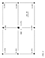
図2の2Aは、図1の実施形態を、図1と同様に示す図である。座標軸を伴う、より多くの光線を描く。図2の2Bは、同じ実施形態の平面図を示す。図1、図2A及び図2Bの実施形態の光学的処方は、ミリメートル及び度の単位で表1に示されている。システムの軸は、図2A及び2Bに示す通りである。中心ずれ(decenter)dYは、Y軸に沿った表面のシフトを表し(すべての表面はX軸に対して中心合わせされている)、回転は、図示された軸を中心としたものである(例えば、X傾斜はX軸を中心とした回転であり、Z傾斜はZ軸を中心とした回転である)。デジタルマイクロミラーデバイス110は、各マイクロミラーの回転軸がデジタルマイクロミラーデバイスの長方形のアクティブ領域のエッジに対して45度だけ角度付けられているので、45度だけクロックされ(すなわち、Z軸を中心に回転され)ている。光源の出力平面の長方形の光源領域も45度だけクロックされており、それにより光源からの光が、それが光送達システム120によってデジタルマイクロミラーデバイスに送られるときに、デジタルマイクロミラーデバイスのアクティブ領域に整合される。
2A of FIG. 2 is a diagram showing the embodiment of FIG. 1 in the same manner as in FIG. Draw more rays with axes. 2B of FIG. 2 shows a plan view of the same embodiment. The optical formulations of the embodiments of FIGS. 1, 2A and 2B are shown in Table 1 in millimeters and degrees. The axes of the system are as shown in FIGS. 2A and 2B. The decenter dY represents the shift of the surface along the Y axis (all surfaces are centered with respect to the X axis) and the rotation is centered on the illustrated axis (). For example, X tilt is a rotation about the X axis, and Z tilt is a rotation around the Z axis). The
表1(及び表2、以下で説明する)の表記法では、各表面に使用される座標系は、先行する表面の座標系のZ軸に沿って、先行する表面の厚さだけの原点オフセットを有し、先行する表面の座標系のX軸又はY軸に沿って、これらの軸に沿った先行する表面の任意のオフセットだけのオフセットを有する。各表面に使用される座標系はまた、先行表面の任意の傾斜だけ、先行表面の座標系に対して回転される。このように、座標系の変化は累積的な効果を有する。座標系の変化(「座標系ブレーク(coordinate system breaks)」又は「座標変更(coordinate changes)」とも呼ばれる)の表記は、Synopsys (https://www.synopsys.com/optical-solutions/codev.html) から入手可能なCode V光学デザインプログラムに従って与えられる。偏心型(decenter type)の「Basic」は、如何なる傾斜が適用される前に、如何なるオフセットが表面に適用されることを意味する。「Decenter & Bend」は、Code Vで使用される座標ブレークの一種である。反射性表面(ミラー)では、反射された主光線に追従するように座標系を設定する。例えば、表1(及び表2)の表面S14〜S16は、隣接する表面の対の間の角度がそれぞれ50度、33.2度、及び96.8度に等しいプリズムを定義している。 In the notation of Table 1 (and Table 2, described below), the coordinate system used for each surface is an origin offset of the thickness of the preceding surface along the Z axis of the coordinate system of the preceding surface. And have an offset of any offset of the preceding surface along these axes along the X or Y axis of the coordinate system of the preceding surface. The coordinate system used for each surface is also rotated relative to the coordinate system of the preceding surface by any inclination of the preceding surface. Thus, changes in the coordinate system have a cumulative effect. The notation of coordinate system changes (also known as "coordinate system breaks" or "coordinate changes") is Synopsys (https://www.synopsys.com/optical-solutions/codev.html). ) Given according to the Code V Optical Design Program available from. The decenter type "Basic" means that any offset is applied to the surface before any inclination is applied. "Decenter & Bend" is a type of coordinate break used in Code V. On the reflective surface (mirror), the coordinate system is set to follow the reflected main ray. For example, surfaces S14-S16 in Table 1 (and Table 2) define prisms in which the angles between pairs of adjacent surfaces are equal to 50 degrees, 33.2 degrees, and 96.8 degrees, respectively.
レンズグループ1のレンズのうちの少なくとも1つのレンズ(例えば、図1及び2Aに示される第2のレンズ112)は、偏心されていてもよい。図1乃至2Bの実施形態では、第2のレンズ112は、主光線をある角度だけ屈曲させる。レンズサブグループ1bのレンズは、入射する主光線の方向に対して偏心させ、傾斜させてもよい。いくつかの実施形態では、レンズサブグループ1bのすべてのレンズは互いに整合されているが、レンズグループ全体は小さな角度(約2〜5度)だけ傾斜される。レンズサブグループ1bのレンズは、適切な製造プロセスにより、容易に達成可能な程度に、互いに位置合わせすることができる。例えば、光軸(又はそれぞれの光軸)は、(i)3〜10分(arc minutes)以内、例えば5分以内に平行(parallel)であり、(ii)0.1〜0.5mm以内、例えば0.2mm以内に共線状(collinear)である。このことは、比較的低コストの設計であってもよく、そのような実施形態では、レンズサブグループ1bのレンズは、像収差を補正するのに役立つが、主光線の方向にはほとんど影響を及ぼさない。レンズグループグループ2のレンズもまた、収差をさらに補正するために、主光線方向に対してわずかに偏心させ傾斜させてもよい。いくつかの実施態様において、第2のレンズ112の代わりに、第1のレンズ111がオフセットされるか、或いはレンズサブグループ1a(レンズサブグループ1aが2個のレンズから構成されるシステムにおいて)の両方のレンズがオフセットされるか、或いはレンズサブグループ1aがオフセットされるレンズ1個のみから構成されてもよい。
At least one of the lenses in lens group 1 (eg, the
レンズグループ1及びレンズグループ2は、質的に異なる機能を実行することができる。例えば、レンズグループ1は、光パイプ105に最も近いレンズグループであってもよく、レンズグループ1は、レンズグループ1を通過した後の光が平行になるか集束されて、レンズグループ2に向かう効果を有してもよい。また、レンズグループ1は、空気スペースだけ、レンズグループ2から分離されてもよい。その空気スペースの厚さ(すなわち、主光線に沿った長さ)は、レンズグループ1の有効焦点距離(EFL)よりも大きい。図1乃至2Bに示す実施形態では、レンズグループ1の有効焦点距離EFLは37.4mm、レンズグループ1とレンズグループ2との間の空気ギャップは67〜68mmである。レンズグループ2を通過した後、光は、第1のプリズム135及び第2のプリズム140を含む全反射プリズムクラスターに入射する。特に、光の集束円錐が、第1のプリズム135の第1の表面を通って第1のプリズム135に入り、第1のプリズム135の第2の(斜め)表面で全反射を経験し、第1のプリズム135の第3の表面を通って第1のプリズム135を出て、デジタルマイクロミラーデバイス110の法線から2A度から(2A + 2度)の角度範囲でデジタルマイクロミラーデバイス110に当たる。ここで、Aはマイクロミラーの傾斜角であり、A = 12度の場合、角度範囲は24〜26度である。デジタルマイクロミラーデバイス110のマイクロミラーがオン状態にある場合、マイクロミラーからの反射の後、光線は、第2のプリズム140を通って投射光学系(図示せず)に向かって方向付けられ、最後にスクリーン(図示せず)に到達する。第1のプリズム110の材料及び角度は、オン状態のマイクロミラーから反射された光の円錐が、全反射の臨界角未満の角度で、第1のプリズム110の斜め面に当たるように選択することができ、従って、反射されずに第2のプリズム140を通過し、投射レンズへと進む。
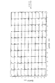
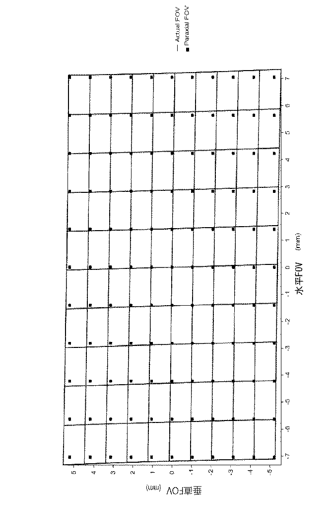
図3は、図1乃至2Bの実施形態のためのシミュレートされた歪みグリッドを示す。図3から分かるように、歪みは、デジタルマイクロミラーデバイス110の4つのコーナーのうちの3つのコーナーにおいて、かなりよく制御されている。詳細には、左上隅に1.96%、右上隅に0.46%、左下隅に0.40%、右下隅に5.1%の歪み値がある。図3において「Paraxial FOV」とラベル付けされた点のグリッドは、理想的な照明光学系の場合のビームフットプリントを示し、デジタルマイクロミラーデバイスのアクティブ領域のアウトラインに対応する。画像歪みを最小化することは、デジタルマイクロミラーデバイス110において照明システムが小さなオーバーフィルマージンを有し、従って、大きな歪みを有するシステムよりも高い光利用効率を有することを可能にし得るという点で有益であり得る。
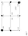
また、光利用効率は、光源からの光がデジタルマイクロミラーデバイス110に如何に緊密に集束されるかにも依存する。より焦点を絞ったシステムは、エッジの遷移がよりシャープであり、従って、過剰オーバーフィルマージンがより小さい可能性がある。二乗平均平方根(RMS)スポットサイズは、レンズ焦点の品質を推定するために使用され得るメトリックであり、より小さなRMSスポットサイズは、一般に、より高い光利用効率をもたらす。図4は、デジタルマイクロミラーデバイス面上の9点における二乗平均平方根スポットサイズ(単位mm)を示す。9点は中心、4つのコーナー及び4つの側部中心である。図4は、スポットのためのスケールバー(「MM」は、測定単位としてミリメートルを意味する)を含む(スポットの分離は、スケールに合わせて描かれていない)。これらの二乗平均平方根スポットサイズ値は、互いに近く、非常に小さく、デジタルマイクロミラーデバイス領域全体にわたって、光がかなり良好に集束されていることを示す。
FIG. 3 shows a simulated strain grid for the embodiments of FIGS. 1-2B. As can be seen from FIG. 3, the distortion is fairly well controlled at three of the four corners of the
The light utilization efficiency also depends on how tightly the light from the light source is focused on the
さらに、図1乃至2Bの実施形態におけるテレセントリック性の程度は比較的高く、この実施形態のシミュレーションは、デジタルマイクロミラーデバイスの異なるマイクロミラーに当たる集束光円錐の主光線が、+/−0.15度以内で互いにテレセントリックであることを示している。 Furthermore, the degree of telecentricity in the embodiments of FIGS. 1 and 2B is relatively high, and the simulation of this embodiment shows that the main ray of the focused light cone that hits the different micromirrors of the digital micromirror device is within +/- 0.15 degrees. It shows that they are telecentric to each other.
レンズグループ1のレンズが偏心も傾斜もしない類似の設計についても分析をし、図1乃至2Bの実施形態における第2のレンズグループ112の偏心及びレンズサブグループ2の傾斜が実施形態の性能にどの程度貢献するかを評価した。この参照設計を図5に示し、その参照設計の光学的処方を表2に示す。
A similar design in which the lens of the
図6は、参照設計のためのシミュレートされた歪みグリッドを示す。歪み値は、左上及び右下で5.1%、右上及び左下で1.1%である。図7は、参照設計のデジタルマイクロミラーデバイス面上の9点における二乗平均平方根スポットサイズ(単位mm)を示し、9点は中心、4つのコーナー及び4つの側部中心である。図7は、スポットのためのスケールバー(「MM」は、測定単位としてミリメートルを意味する)を含む(スポットの分離は、スケールに合わせて描かれていない)。
FIG. 6 shows a simulated strain grid for a reference design. The distortion values are 5.1% at the upper left and lower right, and 1.1% at the upper right and lower left. FIG. 7 shows the root mean square spot size (unit: mm) at 9 points on the surface of the digital micromirror device of the reference design, where 9 points are the center, the four corners, and the four side centers. FIG. 7 includes a scale bar for spots (“MM” means millimeters as a unit of measure) (spot separations are not drawn to scale).
用語「第1」、「第2」、「第3」などは、種々の要素、構成要素、領域、層、及び/又はセクションを説明するために本明細書で使用することができるが、これらの要素、構成要素、領域、層、及び/又はセクションは、これらの用語によって限定されるべきではないことが理解されよう。これらの用語は、1つの要素、構成要素、領域、層又はセクションを別の要素、構成要素、領域、層又はセクションから区別するためにのみ使用される。従って、以下に説明する第1の要素、構成要素、領域、層又はセクションは、本発明の概念の精神及び範囲から逸脱することなく、第2の要素、構成要素、領域、層又はセクションと呼ぶことができる。 The terms "first," "second," "third," and the like can be used herein to describe various elements, components, areas, layers, and / or sections. It will be appreciated that the elements, components, areas, layers, and / or sections of are not limited by these terms. These terms are used only to distinguish one element, component, area, layer or section from another element, component, area, layer or section. Therefore, the first element, component, area, layer or section described below is referred to as the second element, component, area, layer or section without departing from the spirit and scope of the concept of the present invention. be able to.
光投射のための照明システムの限定された実施形態が、本明細書中に具体的に記載及び図示されているが、多くの修正及び変形が当業者には明らかであろう。従って、本発明の原理に従って使用される光投射のための照明システムは、本明細書に具体的に記載される以外に実施され得ることが理解されるべきである。本発明は、以下の特許請求の範囲及びその均等物においても定義される。 Although limited embodiments of lighting systems for light projection are specifically described and illustrated herein, many modifications and modifications will be apparent to those skilled in the art. Therefore, it should be understood that lighting systems for light projection used in accordance with the principles of the present invention can be implemented beyond those specifically described herein. The present invention is also defined in the following claims and their equivalents.
Claims (14)
第1の複数のレンズを含む第1のレンズグループと;
1つ以上のレンズを含む第2のレンズグループと;
を含み、
前記第1のレンズグループの第1のレンズが:
回転対称の前面と;
回転対称の後面と;
有効焦点距離と;
前記回転対称の前面及び前記回転対称の後面によって定義される光軸と;
を有し、
前記前面と前記後面との間の前記光軸の部分の中間点が、前記第1のレンズの有効焦点距離の少なくとも5%だけ前記主光線からオフセットされており、
前記第1のレンズグループは:
第1のレンズサブグループと;
第2のレンズサブグループと;
を含み、
前記第1のレンズサブグループは、前記第1のレンズ及び第2のレンズを含み、前記第1のレンズ及び前記第2のレンズは、2mm未満だけ軸方向に離間されており、前記第2のレンズの光軸が前記主光線からオフセットされておらず、
前記第2のレンズサブグループは、第3のレンズ及び第4のレンズを含み、前記第3のレンズ及び前記第4のレンズは2mm未満だけ軸方向に離間されており、
前記第2のレンズサブグループは、前記第3のレンズ及び前記第4のレンズを含む複数のレンズを有し、
前記第2のレンズサブグループの前記複数のレンズの各レンズは、
回転対称の前面と;
回転対称の後面と;
前記回転対称の前面及び前記回転対称の後面により定義される光軸と;
を有し、
前記第2のレンズサブグループの光軸の各々は、主光線に対して少なくとも2度だけ傾斜しており、
前記第2のレンズサブグループの前記複数のレンズの、前記前面と前記後面との間の、前記光軸の前記部分の中間点は、前記主光線から大きくとも1mmだけオフセットされている、
光学システム。 An optical system with a main ray for receiving light from the light source region of the output plane of the light source and producing spatially modulated light:
With a first lens group that includes a first plurality of lenses;
With a second lens group containing one or more lenses;
Including
The first lens of the first lens group is:
With a rotationally symmetric front surface;
With the rear surface of rotational symmetry;
With effective focal length;
With the optical axis defined by the rotationally symmetric front surface and the rotationally symmetric rear surface;
Have,
Midpoint of the portion of the optical axis between the front and the rear surface is offset from at least by 5% the principal ray of the effective focal length of the first lens,
The first lens group is:
With the first lens subgroup;
With the second lens subgroup;
Including
The first lens subgroup includes the first lens and the second lens, the first lens and the second lens being axially separated by less than 2 mm, the second lens. The optical axis of the lens is not offset from the main ray,
The second lens subgroup includes a third lens and a fourth lens, the third lens and the fourth lens being axially separated by less than 2 mm.
The second lens subgroup has a plurality of lenses including the third lens and the fourth lens.
Each lens of the plurality of lenses in the second lens subgroup
With a rotationally symmetric front surface;
With the rear surface of rotational symmetry;
With the optical axis defined by the rotationally symmetric front surface and the rotationally symmetric rear surface;
Have,
Each of the optical axes of the second lens subgroup is tilted at least 2 degrees with respect to the main ray.
The midpoint of the portion of the optical axis between the front surface and the rear surface of the plurality of lenses in the second lens subgroup is offset by at most 1 mm from the main ray.
Optical system.
前記第1のレンズグループは、有効焦点距離を有し、
当該光学システムは、前記第1のレンズグループと前記第2のレンズグループとの間に、前記第1のレンズグループの有効焦点距離の少なくとも1.4倍のギャップを含む、
光学システム。 The optical system according to claim 1.
The first lens group has an effective focal length and
The optical system includes a gap between the first lens group and the second lens group that is at least 1.4 times the effective focal length of the first lens group.
Optical system.
前記光源領域の中間点から発生する光線が、前記ギャップ内において、
平行である、或いは
半角が10度未満の集束円錐である、
光学システム。 The optical system according to claim 2.
Light rays generated from the midpoint of the light source region are emitted in the gap.
A focused cone that is parallel or has a half-width less than 10 degrees.
Optical system.
前記第2のレンズサブグループの前記レンズの前記光軸は、0.2度以内で互いに整合されている、光学システム。 The optical system according to claim 1.
An optical system in which the optical axes of the lenses of the second lens subgroup are aligned with each other within 0.2 degrees.
前記第2のレンズサブグループの前記複数のレンズの各光学軸の各々は、前記主光線に対して少なくとも2度だけ傾斜されている、光学システム。 The optical system according to claim 1.
An optical system in which each of the optical axes of the plurality of lenses in the second lens subgroup is tilted by at least two degrees with respect to the principal ray.
前記プリズムは:
第1の平坦表面と;
第2の平坦表面と;
第3の平坦表面と;
を有し、
前記プリズムは、第1の屈折率を有する透明材料で構成され、
前記主光線が、前記第1の平坦表面を通してプリズムに入射し、前記プリズムの内部から前記第2の平坦表面の内部法線ベクトルに対して第1の角度で前記第2の平坦表面に当たり、前記第1の角度は、前記第1の屈折率の逆数の逆正弦関数よりも大きい、
光学システム。 The optical system according to claim 1, further comprising a prism.
The prism is:
With the first flat surface;
With a second flat surface;
With a third flat surface;
Have,
The prism is made of a transparent material having a first refractive index.
The main ray enters the prism through the first flat surface and hits the second flat surface from the inside of the prism at a first angle with respect to the internal normal vector of the second flat surface. The first angle is larger than the inverse sine function of the inverse of the first refractive index.
Optical system.
前記主光線が、
前記第2の平坦表面から反射され、
前記第3の平坦表面を通って前記プリズムを出射し、
前記デジタルマイクロミラーデバイスから反射され、
前記第3の平坦表面を通して前記プリズムに再進入し、
前記第2の平坦表面を通って前記プリズムを出射する、
光学システム。 The optical system according to claim 6, further comprising a digital micromirror device on and parallel to the third flat surface of the prism.
The main ray
Reflected from the second flat surface
The prism is emitted through the third flat surface and
Reflected from the digital micromirror device
Re-enter the prism through the third flat surface and
The prism is emitted through the second flat surface.
Optical system.
前記第1のレンズグループは:
第1のレンズサブグループと;
第2のレンズサブグループと;
を含み、
前記第1のレンズサブグループは、前記第1のレンズ及び第2のレンズを含み、前記第1のレンズ及び前記第2のレンズは、2mm未満だけ軸方向に離間されており、
前記第2のレンズサブグループは、第3のレンズ及び第4のレンズを含み、前記第3のレンズ及び前記第4のレンズは2mm未満だけ軸方向に分離されている、
光学システム。 The optical system according to claim 7.
The first lens group is:
With the first lens subgroup;
With the second lens subgroup;
Including
The first lens subgroup includes the first lens and the second lens, and the first lens and the second lens are axially separated by less than 2 mm.
The second lens subgroup includes a third lens and a fourth lens, the third lens and the fourth lens being axially separated by less than 2 mm.
Optical system.
前記第1のレンズグループは、有効焦点距離を有し、
当該光学システムは、前記第1のレンズグループと前記第2のレンズグループとの間に、前記第1のレンズグループの有効焦点距離の少なくとも1.4倍のギャップを含む、
光学システム。 The optical system according to claim 8.
The first lens group has an effective focal length and
The optical system includes a gap between the first lens group and the second lens group that is at least 1.4 times the effective focal length of the first lens group.
Optical system.
前記光源領域の中間点から発生する光線が、前記ギャップ内において、
平行である、或いは
半角が10度未満の集束円錐である、
光学システム。 The optical system according to claim 9.
Light rays generated from the midpoint of the light source region are emitted in the gap.
A focused cone that is parallel or has a half-width less than 10 degrees.
Optical system.
前記第2のレンズサブグループは、前記第3のレンズ及び前記第4のレンズを含む複数のレンズを有し、
前記第2のレンズサブグループの前記複数のレンズの各レンズは、
回転対称の前面と;
回転対称の後面と;
前記回転対称の前面及び前記回転対称の後面により定義される光軸と;
を有し、
前記第2のレンズサブグループの光軸の各々は、主光線に対して少なくとも2度だけ傾斜している、
光学システム。 The optical system according to claim 9.
The second lens subgroup has a plurality of lenses including the third lens and the fourth lens.
Each lens of the plurality of lenses in the second lens subgroup
With a rotationally symmetric front surface;
With the rear surface of rotational symmetry;
With the optical axis defined by the rotationally symmetric front surface and the rotationally symmetric rear surface;
Have,
Each of the optical axes of the second lens subgroup is tilted at least 2 degrees with respect to the main ray.
Optical system.
前記第2のレンズサブグループの前記レンズの前記光軸は、0.2度以内で互いに整合されている、光学システム。 The optical system according to claim 11.
An optical system in which the optical axes of the lenses of the second lens subgroup are aligned with each other within 0.2 degrees.
前記第2のレンズサブグループの前記複数のレンズの、前記前面と前記後面との間の、前記光軸の前記部分の中間点は、前記主光線から大きくとも1mmだけオフセットされている、光学システム。 The optical system according to claim 12.
An optical system in which the midpoint of the portion of the optical axis between the front surface and the rear surface of the plurality of lenses in the second lens subgroup is offset by at most 1 mm from the main ray. ..
前記第2のレンズサブグループの前記第3のレンズ及び前記第4のレンズの各光学軸の各々は、前記主光線に対して少なくとも2度だけ傾斜されている、光学システム。 The optical system according to claim 9.
An optical system in which each of the optic axes of the third lens and the fourth lens of the second lens subgroup is tilted by at least two degrees with respect to the principal ray.
Applications Claiming Priority (1)
| Application Number | Priority Date | Filing Date | Title |
|---|---|---|---|
| PCT/CA2017/051531 WO2019119099A1 (en) | 2017-12-18 | 2017-12-18 | Illumination system for light projection |
Publications (2)
| Publication Number | Publication Date |
|---|---|
| JP2020537195A JP2020537195A (en) | 2020-12-17 |
| JP6896183B2 true JP6896183B2 (en) | 2021-06-30 |
Family
ID=66992493
Family Applications (1)
| Application Number | Title | Priority Date | Filing Date |
|---|---|---|---|
| JP2020541835A Active JP6896183B2 (en) | 2017-12-18 | 2017-12-18 | Lighting system for floodlight |
Country Status (7)
| Country | Link |
|---|---|
| US (1) | US11294153B2 (en) |
| EP (1) | EP3729183B1 (en) |
| JP (1) | JP6896183B2 (en) |
| AU (1) | AU2017444080B2 (en) |
| CA (1) | CA3075863A1 (en) |
| NZ (1) | NZ763020A (en) |
| WO (1) | WO2019119099A1 (en) |
Families Citing this family (1)
| Publication number | Priority date | Publication date | Assignee | Title |
|---|---|---|---|---|
| KR102632409B1 (en) * | 2020-10-23 | 2024-02-02 | 돌비 레버러토리즈 라이쎈싱 코오포레이션 | Projection system and method utilizing adjustable angle illumination using lens decentering |
Family Cites Families (16)
| Publication number | Priority date | Publication date | Assignee | Title |
|---|---|---|---|---|
| JPH0675192A (en) * | 1992-06-26 | 1994-03-18 | Minolta Camera Co Ltd | Camera shake correcting optical system |
| US6124972A (en) * | 1994-03-18 | 2000-09-26 | Canon Kabushiki Kaisha | Zoom lens having an image stabilizing function |
| US5914818A (en) * | 1996-11-29 | 1999-06-22 | Texas Instruments Incorporated | Offset projection lens for use with reflective spatial light modulators |
| JP3686887B2 (en) | 2002-07-11 | 2005-08-24 | Necビューテクノロジー株式会社 | Illumination optical system and enlarged projection display device |
| KR100765274B1 (en) * | 2003-02-27 | 2007-10-09 | 엘지전자 주식회사 | Projection-type display optical system |
| JP4063782B2 (en) * | 2003-05-30 | 2008-03-19 | Necディスプレイソリューションズ株式会社 | Illumination optical system and projection display device |
| JP2005099669A (en) * | 2003-08-27 | 2005-04-14 | Casio Comput Co Ltd | Projection display device |
| US20060139730A1 (en) * | 2004-12-23 | 2006-06-29 | Oehler Peter R | Illumination system with compact turning prism and projection system using same |
| WO2008068257A1 (en) | 2006-12-05 | 2008-06-12 | Thomson Licensing | Projection image display device having two modulation stages |
| TWI394982B (en) * | 2009-06-03 | 2013-05-01 | Young Optics Inc | Projection apparatus and projection lens |
| TWI427323B (en) * | 2011-02-18 | 2014-02-21 | Young Optics Inc | Projection lens and projection apparatus |
| EP2835677B1 (en) * | 2012-12-28 | 2020-05-27 | Nittoh Inc. | Projection optical system and projector device |
| JP2015219434A (en) * | 2014-05-20 | 2015-12-07 | キヤノン株式会社 | Illumination optical system and image projection device |
| JP2016180818A (en) * | 2015-03-23 | 2016-10-13 | キヤノン株式会社 | Illumination optical system and projection type display device using the same |
| US10281805B2 (en) * | 2015-07-17 | 2019-05-07 | Nec Display Solutions, Ltd. | Image display device and image display method |
| CN207424359U (en) * | 2017-08-03 | 2018-05-29 | 江西凤凰光学科技有限公司上海分公司 | A kind of big vehicle-mounted Optical devices of target surface ultra-wide angle high definition of large aperture |
-
2017
- 2017-12-18 EP EP17935264.6A patent/EP3729183B1/en active Active
- 2017-12-18 CA CA3075863A patent/CA3075863A1/en active Pending
- 2017-12-18 NZ NZ763020A patent/NZ763020A/en unknown
- 2017-12-18 WO PCT/CA2017/051531 patent/WO2019119099A1/en active Application Filing
- 2017-12-18 US US16/761,229 patent/US11294153B2/en active Active
- 2017-12-18 AU AU2017444080A patent/AU2017444080B2/en active Active
- 2017-12-18 JP JP2020541835A patent/JP6896183B2/en active Active
Also Published As
| Publication number | Publication date |
|---|---|
| WO2019119099A1 (en) | 2019-06-27 |
| AU2017444080B2 (en) | 2023-06-29 |
| EP3729183B1 (en) | 2023-09-13 |
| EP3729183A1 (en) | 2020-10-28 |
| AU2017444080A1 (en) | 2020-07-09 |
| NZ763020A (en) | 2022-04-29 |
| US20200355894A1 (en) | 2020-11-12 |
| EP3729183A4 (en) | 2021-04-14 |
| JP2020537195A (en) | 2020-12-17 |
| CA3075863A1 (en) | 2019-06-27 |
| US11294153B2 (en) | 2022-04-05 |
Similar Documents
| Publication | Publication Date | Title |
|---|---|---|
| CN105988207B (en) | Magnifying optics, optical unit and projector apparatus | |
| JP4032658B2 (en) | Projection display | |
| TWI440986B (en) | Catoptric illumination system for microlithography tool | |
| JP5648616B2 (en) | Image display device | |
| KR101213636B1 (en) | Projector for projecting an image and corresponding method | |
| US7055959B2 (en) | Projection display device and back projection display device using the display device | |
| JP5691962B2 (en) | Image display device | |
| CN106226984A (en) | A kind of LASER Light Source, laser projection device | |
| JP3640391B1 (en) | Illumination optics | |
| JP6896183B2 (en) | Lighting system for floodlight | |
| JP2015219434A (en) | Illumination optical system and image projection device | |
| JP2008242238A (en) | Exposure apparatus | |
| Ley et al. | Imaging and non-imaging illumination of DLP for high resolution headlamps | |
| JP2000089227A (en) | Projection type display device | |
| JP4510399B2 (en) | Reflective optical system and projection apparatus using the same | |
| JP5975089B2 (en) | Projection optical system and image display device | |
| WO2020209374A1 (en) | Optical system | |
| US20020126392A1 (en) | Projection system utilizing asymmetric etendue | |
| TWI239428B (en) | Projection display apparatus | |
| Bowron et al. | Off-axis illumination design for DMD systems | |
| CN106200238A (en) | Imaging optical path system | |
| JPS63114186A (en) | Lighting apparatus | |
| CN210136386U (en) | Light integration rod and projection device | |
| JP2016186659A (en) | Projection optical system and image display device | |
| CN109884842B (en) | Projector with a light source |
Legal Events
| Date | Code | Title | Description |
|---|---|---|---|
| A621 | Written request for application examination |
Free format text: JAPANESE INTERMEDIATE CODE: A621 Effective date: 20200413 |
|
| A131 | Notification of reasons for refusal |
Free format text: JAPANESE INTERMEDIATE CODE: A131 Effective date: 20210224 |
|
| A521 | Request for written amendment filed |
Free format text: JAPANESE INTERMEDIATE CODE: A523 Effective date: 20210413 |
|
| TRDD | Decision of grant or rejection written | ||
| A01 | Written decision to grant a patent or to grant a registration (utility model) |
Free format text: JAPANESE INTERMEDIATE CODE: A01 Effective date: 20210511 |
|
| A61 | First payment of annual fees (during grant procedure) |
Free format text: JAPANESE INTERMEDIATE CODE: A61 Effective date: 20210608 |
|
| R150 | Certificate of patent or registration of utility model |
Ref document number: 6896183 Country of ref document: JP Free format text: JAPANESE INTERMEDIATE CODE: R150 |