JP6895805B2 - Fireproof structure of compartment penetration - Google Patents

Fireproof structure of compartment penetration Download PDF

Info

Publication number
JP6895805B2
JP6895805B2 JP2017107308A JP2017107308A JP6895805B2 JP 6895805 B2 JP6895805 B2 JP 6895805B2 JP 2017107308 A JP2017107308 A JP 2017107308A JP 2017107308 A JP2017107308 A JP 2017107308A JP 6895805 B2 JP6895805 B2 JP 6895805B2
Authority
JP
Japan
Prior art keywords
tubular
peripheral surface
penetrating member
bus duct
penetrating
Prior art date
Legal status (The legal status is an assumption and is not a legal conclusion. Google has not performed a legal analysis and makes no representation as to the accuracy of the status listed.)
Active
Application number
JP2017107308A
Other languages
Japanese (ja)
Other versions
JP2018201630A5 (en
JP2018201630A (en
Inventor
達朗 上平
達朗 上平
神保 紘史
紘史 神保
允健 谷口
允健 谷口
龍二 鉦谷
龍二 鉦谷
Current Assignee (The listed assignees may be inaccurate. Google has not performed a legal analysis and makes no representation or warranty as to the accuracy of the list.)
Mitsubishi Electric Corp
Original Assignee
Mitsubishi Electric Corp
Priority date (The priority date is an assumption and is not a legal conclusion. Google has not performed a legal analysis and makes no representation as to the accuracy of the date listed.)
Filing date
Publication date
Application filed by Mitsubishi Electric Corp filed Critical Mitsubishi Electric Corp
Priority to JP2017107308A priority Critical patent/JP6895805B2/en
Publication of JP2018201630A publication Critical patent/JP2018201630A/en
Publication of JP2018201630A5 publication Critical patent/JP2018201630A5/ja
Application granted granted Critical
Publication of JP6895805B2 publication Critical patent/JP6895805B2/en
Active legal-status Critical Current
Anticipated expiration legal-status Critical

Links

Images

Landscapes

  • Building Environments (AREA)
  • Installation Of Bus-Bars (AREA)

Description

この発明は、発変電施設やビル・工場などの建築物の仕切り部に形成された貫通部材を有する区画貫通部の耐火構造に関するものである。 The present invention relates to a fireproof structure of a compartment penetrating portion having a penetrating member formed in a partition portion of a building such as a power generation / transformation facility or a building / factory.

建築物の区画貫通部の内、安全上重要な区画間の貫通部は、いずれかの区画で火災が発生した際に、他の区画への延焼を防止する構造とすることが要求されている。
区画貫通部の貫通部材としては、帯状導体を金属筐体で囲んだ長尺の構造物であるバスダクトを含め、ケーブル、配管、電線等がある。
Of the section penetrations of buildings, the penetrations between sections that are important for safety are required to have a structure that prevents the spread of fire to other sections in the event of a fire in one of the sections. ..
Penetrating members of the section penetrating portion include cables, pipes, electric wires, and the like, including a bus duct which is a long structure in which a strip-shaped conductor is surrounded by a metal housing.

安全上重要な区画貫通部のバスダクトは、耐火壁に設けた開口部を貫通しており、耐火壁とバスダクトとの間の隙間をモルタル等によって埋めた構造となっている。片側の区画で火災が発生した際の延焼プロセスとして、バスダクト内部を通り道として炎が区画を貫通する場合と、バスダクトが熱変形し、耐火壁との間に生じた隙間を通って炎が区画を貫通する場合とがある。 The bus duct of the compartment penetration part, which is important for safety, penetrates the opening provided in the refractory wall, and has a structure in which the gap between the refractory wall and the bus duct is filled with mortar or the like. When a fire breaks out in one section, the flame spreads through the section through the inside of the bus duct, and the flame deforms through the section due to thermal deformation of the bus duct, and the flame passes through the gap created between the section and the fireproof wall. It may penetrate.

特許第3824358号公報(図3参照)Japanese Patent No. 3824358 (see FIG. 3) 特開2016−10184号公報(図1、図3、図13参照)Japanese Unexamined Patent Publication No. 2016-10184 (see FIGS. 1, 3, and 13)

特許文献1では、その図3に示されるように、建築物の区画を貫通するバスダクトの外周面に熱膨張性部材を設置し、更にその熱膨張性部材表面に、高温ガスを遮断するゴム成分を含有するシール層を密着させることで、バスダクト外周の熱変形により耐火壁とバスダクト間に生じた隙間を熱膨張性部材が追従して埋めることで区画間の熱の伝達を防止することが可能な延焼防止装置が提案されている。
しかし、原子力に関する新規制基準の制定により、従来の2時間耐火を超える、3時間の耐火性能が要求されており、バスダクトの到達温度が上昇し、熱変形量が増大する可能性がある。この場合、熱膨張性部材のみでの追従が困難である。
In Patent Document 1, as shown in FIG. 3, a heat-expandable member is installed on the outer peripheral surface of a bus duct penetrating a section of a building, and a rubber component that blocks high-temperature gas is further provided on the surface of the heat-expandable member. By adhering the seal layer containing the above, the heat expansion member can follow and fill the gap created between the refractory wall and the bus duct due to the thermal deformation of the outer circumference of the bus duct, and it is possible to prevent heat transfer between the compartments. A fire spread prevention device has been proposed.
However, due to the establishment of new regulatory standards for nuclear power, fire resistance for 3 hours, which exceeds the conventional fire resistance for 2 hours, is required, and the temperature reached by the bus duct may rise, resulting in an increase in the amount of thermal deformation. In this case, it is difficult to follow with only the heat-expandable member.

特許文献2では、その図1および図3に示されるように、耐火壁を貫通する矩形状バスダクトの外周面に補強金具を取り付けて剛性を高め、補強金具内部に熱膨張性部材を設置することで、熱変形によって生じた、バスダクトとモルタル間の隙間を埋める延焼防止装置が提案されている。
しかし、バスダクト外周面に取り付ける補強金具は剛性を高めるため、一定以上の板厚、外形で製作する必要があり、バスダクト周囲に配管等が近接している場合に取り付け不可能となる。
In Patent Document 2, as shown in FIGS. 1 and 3, a reinforcing metal fitting is attached to the outer peripheral surface of a rectangular bus duct penetrating a fireproof wall to increase rigidity, and a heat-expandable member is installed inside the reinforcing metal fitting. Therefore, a fire spread prevention device that fills the gap between the bath duct and the mortar caused by thermal deformation has been proposed.
However, in order to increase the rigidity of the reinforcing metal fittings to be attached to the outer peripheral surface of the bus duct, it is necessary to manufacture the reinforcing metal fittings with a plate thickness and an outer shape of a certain value or more, and it becomes impossible to attach the reinforcing metal fittings when the pipes or the like are close to each other around the bus duct.

また、特許文献2では、その図13に示されるように、耐火壁を貫通するバスダクトの外周面に耐火用シートおよび耐火用シート固定金具、結束バンドを取り付け、耐火用シートの内部に熱膨張性部材を設置することで、熱変形によって生じた隙間を埋めた上で、耐火用シートによってバスダクトを覆うことで延焼を防止する構造が提案されているが、バスダクト全周に耐火用シートを取り付ける作業の施工性が悪く、また、耐火用シートによってバスダクトの通風孔および点検口を覆ってしまう場合があり、換気性能およびメンテナンス性悪化のリスクがある。 Further, in Patent Document 2, as shown in FIG. 13, a refractory sheet, a refractory sheet fixing bracket, and a binding band are attached to the outer peripheral surface of the bus duct penetrating the refractory wall, and the refractory sheet is thermally expandable. A structure has been proposed to prevent the spread of fire by covering the bus duct with a fireproof sheet after filling the gap created by thermal deformation by installing members, but the work of attaching the fireproof sheet to the entire circumference of the bus duct. The workability is poor, and the fireproof sheet may cover the ventilation holes and inspection port of the bus duct, and there is a risk of deterioration of ventilation performance and maintainability.

この発明による区画貫通部の耐火構造は、建築物の仕切り壁に形成された開口部を貫通
し前記開口部の内面に対応して前記仕切り壁の一側から他側に及ぶ連通領域を内部に有す
る筒状貫通部材と、前記筒状貫通部材の内部で前記筒状貫通部材の軸線に沿い前記連通領
域を通って延在する内在伸延部材を備え、前記連通領域において前記内在伸延部材の外周
面と前記筒状貫通部材の内周面との間を封塞し前記仕切り壁の一側から他側への連通を阻
止する仕切りと、前記連通領域の前記筒状貫通部材の外周面と前記仕切り壁の前記開口部の内面との間に装着されたモルタル層と、前記連通領域の前記筒状貫通部材の内周面に設けられた補強具とを備えたことを特徴とするものである。
The fireproof structure of the partition penetrating portion according to the present invention penetrates the opening formed in the partition wall of the building and has a communication region internally extending from one side to the other side of the partition wall corresponding to the inner surface of the opening. The tubular penetrating member includes an internal extending member that extends through the communication region along the axis of the tubular penetrating member inside the tubular penetrating member, and an outer peripheral surface of the internal extending member in the communicating region. wherein and the partition you blocking the communication to the other side from one side of Fu塞and the partition wall between the inner peripheral surface of the tubular penetrating member, the outer peripheral surface of the tubular penetrating member of the communication area and It is characterized by including a mortar layer mounted between the inner surface of the opening of the partition wall and a reinforcing tool provided on the inner peripheral surface of the tubular penetrating member in the communication region. ..

この発明によれば、建築物の仕切り壁を貫通し内在伸延部材を設けた筒状貫通部材の内部における連通領域が封塞されるため、火災発生区画側から非火災発生区画側への筒状貫通部材の内部における炎や熱の移動が制限され、温度上昇が低減される。このことにより、非火災発生区画側における筒状貫通部材の熱変形量が抑えられる。 According to the present invention, since the communication area inside the tubular penetrating member that penetrates the partition wall of the building and is provided with the internal extension member is closed, the tubular shape from the fire occurrence section side to the non-fire occurrence section side. The transfer of flames and heat inside the penetrating member is restricted and the temperature rise is reduced. As a result, the amount of thermal deformation of the tubular penetrating member on the non-fire generation section side can be suppressed.

この発明による実施の形態1における区画貫通部の耐火構造に係る構成を示す断面図である。It is sectional drawing which shows the structure which concerns on the fire-resistant structure of the section penetration part in Embodiment 1 by this invention. この発明による実施の形態2における区画貫通部の耐火構造に係る構成を示す断面図である。It is sectional drawing which shows the structure which concerns on the fire-resistant structure of the section penetration part in Embodiment 2 by this invention. この発明による実施の形態3における区画貫通部の耐火構造に係る構成を示す断面図であり、図3(a)は貫通部の構造を示す側断面図、図3(b)は熱膨張性部材23の取り付け部を示す拡大図である。It is sectional drawing which shows the structure which concerns on the fire-resistant structure of the section penetration part in Embodiment 3 by this invention, FIG. 3A is a side sectional view which shows the structure of a penetration part, and FIG. 3B is a heat-expandable member. It is an enlarged view which shows the attachment part of 23. この発明による実施の形態4における区画貫通部の耐火構造に係る構成を示す断面図であり、図4(a)は貫通部の構造を示す側断面図、図4(b)は耐火用シート17の取り付け部を示す拡大図である。It is sectional drawing which shows the structure which concerns on the fireproof structure of the section penetration part in Embodiment 4 by this invention, FIG. 4A is a side sectional view which shows the structure of a penetration part, and FIG. 4B is a fireproof sheet 17. It is an enlarged view which shows the attachment part of. この発明による実施の形態5における区画貫通部の耐火構造に係る構成を示す断面図であり、図5(a)は貫通部の構造を示す側断面図、図5(b)は熱膨張性部材23の取り付け部を示す拡大図である。It is sectional drawing which shows the structure which concerns on the fire-resistant structure of the section penetration part in Embodiment 5 by this invention, FIG. 5A is a side sectional view which shows the structure of the penetration part, and FIG. It is an enlarged view which shows the attachment part of 23. この発明による実施の形態6における区画貫通部の耐火構造に係る構成を示す断面図であり、図6(a)は貫通部の構造を示す側断面図、図6(b)は熱膨張性部材23の取り付け部を拡大して示す図である。FIG. 6A is a cross-sectional view showing a configuration related to a fireproof structure of a compartment penetrating portion according to a sixth embodiment according to the present invention, FIG. 6A is a side cross-sectional view showing the structure of the penetrating portion, and FIG. It is a figure which shows the attachment part of 23 in an enlarged view. この発明による実施の形態7における区画貫通部の耐火構造に係る構成を示す断面図であり、図7(a)は貫通部の構造を示す側断面図、図7(b)は点検口22の構造を概略的に示す断面図である。FIG. 7 (a) is a side sectional view showing the structure of the penetration portion, and FIG. 7 (b) is the inspection port 22 of the inspection port 22. It is sectional drawing which shows the structure schematicly.

実施の形態1.
以下、この発明による実施の形態1に係る区画貫通部の耐火構造について、図1を参照して説明する。図1は区画貫通部の構成を示す断面図である。
図1は発変電施設やビル・工場などの建築物の区画間に配設された耐火壁(仕切り壁)14の開口部NPを貫通し区画貫通部SPを構成している角筒状のバスダクト11からなる筒状貫通部材を示している。このバスダクト11の中にはバスダクト11の軸線に沿って内在伸延部材としてのブスバー12が配置されている。バスダクト11の外周面は開口部NPの内周面を形成するモルタル層16と接合し、バスダクト11の内部には、耐火用厚さ寸法STを有する耐火壁14の一側面14Aから他側面14Bに及ぶ範囲に対応し、開口部NPの内周面を形成するモルタル層16とバスダクト11が接する範囲内において、連通領域SRが形成され、ブスバー12からなる内在伸延部材は連通領域SRを通り延在する。ブスバー12は銅製の帯状導体で構成され、バスダクト11は帯状導体からなるブスバー12を接地電位に保持された金属製筺体からなる導電性外被部材で囲んだ長尺の構造物として構成されている。ブスバー12はバスダクト11の導電性外被部材から電気的に絶縁されてバスダクト11の軸線部分において機械的に支持される。
そして、連通領域SRの領域内であり耐火壁14の開口部NPに形成されたモルタル層16とバスダクト11が接する範囲内において、難燃材または不燃材からなる樹脂積層成形物で構成される四角形状パネル部材を形成する仕切り20を取り付けて、四方枠状の仕切り固定金具21で固定する。仕切り20と仕切り固定金具21で構成される封塞部材FSはバスダクト11の軸線と直交方向に延在し、バスダクト11の内部で連通領域SRを封塞してバスダクト11の内部における軸線方向の炎や熱の移動を規制する。バスバー12からなる内在伸延部材は仕切り20と仕切り固定金具21からなる封塞部材FSを構成する四角形状パネル部材を形成する仕切り20の中央部を仕切り20の延在方向と直交して貫通し、この貫通部分におけるバスバー12の外周面と仕切り20の内周面との間は密封処理される。仕切り20と仕切り固定金具21からなる封塞部材FSが火災発生区画側のバスダクト11から非火災発生区画側のバスダクト11への炎や熱の移動を制限し、温度上昇が低減され、バスダクト11外周の熱変形量が抑えられる。このことにより、バスダクト11とモルタル層16間の隙間発生およびバスダクト11内からの炎の噴出を防ぎ、区画間の延焼を防止できる。
また、バスダクト11外周に大きなスペースを必要としない構造とすることで、バスダクト11の周囲条件に左右されず、加えて換気性能およびメンテナンス性悪化のリスクなしで耐火性能の向上が可能となる。
Embodiment 1.
Hereinafter, the fireproof structure of the compartment penetrating portion according to the first embodiment according to the present invention will be described with reference to FIG. FIG. 1 is a cross-sectional view showing the configuration of a section penetrating portion.
FIG. 1 shows a square tubular bus duct that penetrates the opening NP of a refractory wall (partition wall) 14 arranged between sections of a building such as a power generation / transformation facility or a building / factory to form a section penetration section SP. A tubular penetrating member made of 11 is shown. In the bus duct 11, a bus bar 12 as an internal extension member is arranged along the axis of the bus duct 11. The outer peripheral surface of the bus duct 11 is joined to the mortar layer 16 forming the inner peripheral surface of the opening NP, and the inside of the bus duct 11 is changed from one side surface 14A of the fireproof wall 14 having the fireproof thickness dimension ST to the other side surface 14B. A communication region SR is formed within the range where the mortar layer 16 forming the inner peripheral surface of the opening NP and the bus duct 11 are in contact with each other, and the internal extension member composed of the bus bar 12 extends through the communication region SR. To do. The bus bar 12 is composed of a copper strip-shaped conductor, and the bus duct 11 is configured as a long structure in which the bus bar 12 made of the strip-shaped conductor is surrounded by a conductive outer member made of a metal housing held at a ground potential. .. The bus bar 12 is electrically insulated from the conductive outer cover member of the bus duct 11 and is mechanically supported at the axial portion of the bus duct 11.
Then, within the area of the communication region SR and within the range where the mortar layer 16 formed in the opening NP of the refractory wall 14 and the bus duct 11 are in contact with each other, a square composed of a resin laminated molded product made of a flame-retardant material or a non-combustible material. A partition 20 forming a shape panel member is attached, and the partition 20 is fixed by a four-sided frame-shaped partition fixing bracket 21. The sealing member FS composed of the partition 20 and the partition fixing bracket 21 extends in the direction orthogonal to the axis of the bus duct 11, seals the communication region SR inside the bus duct 11, and flames in the axial direction inside the bus duct 11. And regulate heat transfer. The internal extension member composed of the bus bar 12 penetrates the central portion of the partition 20 forming the rectangular panel member constituting the sealing member FS composed of the partition 20 and the partition fixing bracket 21 at right angles to the extending direction of the partition 20. The outer peripheral surface of the bus bar 12 and the inner peripheral surface of the partition 20 in this penetrating portion are sealed. The sealing member FS composed of the partition 20 and the partition fixing bracket 21 limits the transfer of flames and heat from the bus duct 11 on the side where the fire has occurred to the bus duct 11 on the side where the fire has occurred, the temperature rise is reduced, and the outer circumference of the bus duct 11 is reduced. The amount of thermal deformation of is suppressed. As a result, it is possible to prevent the generation of a gap between the bath duct 11 and the mortar layer 16 and the ejection of flame from the inside of the bus duct 11 and prevent the spread of fire between the sections.
Further, by adopting a structure that does not require a large space on the outer periphery of the bus duct 11, it is possible to improve the fire resistance performance without being affected by the surrounding conditions of the bus duct 11 and without the risk of deterioration of ventilation performance and maintainability.

図1で取り付けた、仕切り20および仕切り固定金具21で構成される封塞部材FSは、どちらの区画で火災が発生した場合でも同等の効果を発揮するために耐火壁14中央に配置することが望ましいが、これらの設置位置および個数に制限はなく、仕切り自身のメンテナンスが不可能とならない範囲で位置を変更し、個数を増やせば、さらに耐火性能を向上させることが可能となる。 The sealing member FS composed of the partition 20 and the partition fixing bracket 21 attached in FIG. 1 may be arranged in the center of the refractory wall 14 in order to exert the same effect regardless of which section a fire occurs. Although it is desirable, there is no limit to the installation position and the number of these, and if the position is changed and the number is increased within the range where the maintenance of the partition itself is not impossible, the fire resistance performance can be further improved.

この発明による実施の形態1における区画貫通部の耐火構造は、建築物の耐火用仕切り壁14に形成された区画貫通部STに設けられる開口部NPを貫通し前記開口部の内面に対応して前記耐火用仕切り壁14の一側面14Aから他側面14Bへの連通領域SRを内部に有する金属筺体で構成された長尺の構造物である角筒状のバスダクト11からなる筒状貫通部材と、前記筒状貫通部材に内在し前記筒状貫通部材の軸線に沿い前記連通領域SRを通って前記筒状貫通部材の内部で延在する帯状導体で構成されるバスバー12からなる線状の内在伸延部材を備え、前記連通領域SRにおいてバスバー12からなる前記内在伸延部材とバスダクト11からなる前記筒状貫通部材の内周面とを封塞し前記耐火用仕切り壁14の一側から他側への連通を阻止する難燃材または不燃材からなる樹脂成型物の四角形状パネル部材を形成する仕切り20と四方枠状の仕切り固定金具21で構成される封塞部材FSを設けたことを特徴とする。
すなわち、建築物の耐火用仕切り壁14に形成された区画貫通部に設けられる開口部NPを貫通するバスダクト11からなる筒状貫通部材の内部に、前記耐火用仕切り壁14に対応する範囲内において、前記筒状貫通部材の長手方向で仕切る難燃材または不燃材からなる仕切り20と仕切り固定金具21を設置したことを特徴とする。
この構成により、建築物の仕切り壁に形成された区画貫通部SPに設けられバスバー12からなる内在伸延部材を内在するバスダクト11からなる筒状貫通部材の内部における連通領域SRが封塞されるため、火災発生区画側のバスダクト11からなる筒状貫通部材から非火災発生区画側の筒状貫通部材への炎や熱の移動が制限され、温度上昇が低減される。このことにより、非火災発生区画側のバスダクト外周の熱変形量が抑えられるものである。
The fireproof structure of the compartment penetrating portion in the first embodiment according to the present invention penetrates the opening NP provided in the compartment penetrating portion ST formed in the fireproof partition wall 14 of the building and corresponds to the inner surface of the opening. A tubular penetrating member made of a square tubular bus duct 11 which is a long structure composed of a metal housing having a communication region SR from one side surface 14A to the other side surface 14B of the refractory partition wall 14 inside. A linear internal extension composed of a bus bar 12 composed of a band-shaped conductor that is inherent in the tubular penetrating member and extends inside the tubular penetrating member through the communication region SR along the axis of the tubular penetrating member. The member is provided, and in the communication region SR, the internal extension member made of the bus bar 12 and the inner peripheral surface of the tubular penetrating member made of the bus duct 11 are sealed, and the fireproof partition wall 14 is transferred from one side to the other side. It is characterized in that a sealing member FS composed of a partition 20 for forming a square panel member of a resin molding made of a refractory material or a non-combustible material for preventing communication and a partition fixing bracket 21 having a square frame shape is provided. ..
That is, within the tubular penetrating member formed of the bus duct 11 penetrating the opening NP provided in the partition penetrating portion formed in the fireproof partition wall 14 of the building, within the range corresponding to the fireproof partition wall 14. A partition 20 made of a flame-retardant material or a non-combustible material and a partition fixing metal fitting 21 for partitioning the tubular penetrating member in the longitudinal direction are installed.
With this configuration, the communication region SR inside the tubular penetrating member composed of the bus duct 11 provided in the compartment penetrating portion SP formed in the partition wall of the building and having the internal extending member consisting of the bus bar 12 is sealed. The transfer of flames and heat from the tubular penetrating member formed of the bus duct 11 on the fire occurrence section side to the tubular penetrating member on the non-fire occurrence section side is restricted, and the temperature rise is reduced. As a result, the amount of thermal deformation on the outer circumference of the bus duct on the non-fire section side can be suppressed.

実施の形態2.
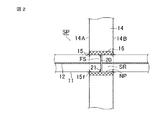
以下、この発明の実施の形態2に係る区画貫通部の耐火構造について、図2を参照して説明する。図2は区画貫通部の構成を示す断面図である。
図2は区画貫通部SPにおいて区画間の耐火壁14を貫通しているバスダクト11を示している。角筒状のバスダクト11に鉄製で枠状の補強金具15を取り付け、さらに、耐火壁14内に樹脂積層成形物の仕切り20を取り付けて、枠状の仕切り固定金具21により固定する。仕切り20および仕切り固定金具21によって構成される封塞部材FSによりバスダクト11の温度上昇が抑えられ、更に、補強金具15によりバスダクト11の剛性が向上し、バスダクト11の熱変形量が大幅に抑えられるため、区画間の延焼を防止できる。尚、仕切り固定金具21は補強金具を兼ねても良い。
バスダクト11の外周面には、耐火壁14の側面14A,14Bにそれぞれ対応して四方枠状の補強金具15が耐火壁14の側面14A,14Bの延在方向に沿って設けられる。四方枠状の補強金具15の内周面はバスダクト11の外周面に補強可能に嵌め込まれて接合され、補強金具15の周縁端部に設けられたフランジ部15fはモルタル層16が設けられた耐火壁14の側面14A,14Bにそれぞれ固定される。
バスダクト11の内周面には、耐火壁14の側面14A,14Bにそれぞれ対応して四方枠状の補強金具15が耐火壁14の側面14A,14Bの延在方向に沿って設けられる。四方枠状の補強金具15の外周面はバスダクト11の内周面に補強可能に嵌め込まれて接合され、補強金具15の周縁端部に設けられたフランジ部15fはモルタル層16が設けられた耐火壁14の側面14A,14Bにそれぞれ固定される。
Embodiment 2.
Hereinafter, the fireproof structure of the compartment penetrating portion according to the second embodiment of the present invention will be described with reference to FIG. FIG. 2 is a cross-sectional view showing the configuration of the section penetrating portion.
FIG. 2 shows a bus duct 11 penetrating the refractory wall 14 between the compartments in the compartment penetration portion SP. A frame-shaped reinforcing metal fitting 15 made of iron is attached to the square tubular bus duct 11, and a partition 20 of a resin laminated molded product is further attached to the refractory wall 14 and fixed by the frame-shaped partition fixing metal fitting 21. The temperature rise of the bus duct 11 is suppressed by the sealing member FS composed of the partition 20 and the partition fixing metal fitting 21, and the rigidity of the bus duct 11 is improved by the reinforcing metal fitting 15, and the amount of thermal deformation of the bus duct 11 is significantly suppressed. Therefore, it is possible to prevent the spread of fire between sections. The partition fixing bracket 21 may also serve as a reinforcing bracket.
On the outer peripheral surface of the bus duct 11, square frame-shaped reinforcing metal fittings 15 are provided along the extending directions of the side surfaces 14A and 14B of the refractory wall 14 corresponding to the side surfaces 14A and 14B of the refractory wall 14, respectively. The inner peripheral surface of the four-sided frame-shaped reinforcing metal fitting 15 is fitted and joined to the outer peripheral surface of the bus duct 11 so as to be reinforced, and the flange portion 15f provided at the peripheral end of the reinforcing metal fitting 15 is fireproof with a mortar layer 16. It is fixed to the side surfaces 14A and 14B of the wall 14, respectively.
On the inner peripheral surface of the bus duct 11, square frame-shaped reinforcing metal fittings 15 are provided along the extending directions of the side surfaces 14A and 14B of the refractory wall 14 corresponding to the side surfaces 14A and 14B of the refractory wall 14, respectively. The outer peripheral surface of the four-sided frame-shaped reinforcing metal fitting 15 is fitted and joined to the inner peripheral surface of the bus duct 11 so as to be reinforced, and the flange portion 15f provided at the peripheral end of the reinforcing metal fitting 15 is fireproof with a mortar layer 16. It is fixed to the side surfaces 14A and 14B of the wall 14, respectively.

図2に示す実施の形態2では、補強金具15を両区画、バスダクト11の内外に取り付けているが、両区画の両側または片側のいずれかに取り付けても良く、また、バスダクト11の内外両方またはいずれかに取り付けても良い。 In the second embodiment shown in FIG. 2, the reinforcing metal fittings 15 are attached to both inside and outside of the bus duct 11, but may be attached to either both sides or one side of both compartments, or both inside or outside the bus duct 11. It may be attached to either.

この発明による実施の形態2における区画貫通部の耐火構造は、前述した実施の形態1における構成において、バスダクト11からなる前記筒状貫通部材の剛性を向上させるものであって、角筒状のバスダクト11の外周面における上下両面および両側面からなる外面四周領域または内周面における上下両面および両側面からなる内面四周領域に嵌め込まれて補強可能に接合し前記筒状貫通部材の延在方向と直交して延在する四方枠状の補強金具15を、前記仕切り壁14の一側面14Aおよび他側面14Bの少なくとも一方に対応してバスダクト11からなる前記筒状貫通部材の内周面および外周面の少なくとも一方に設けたことを特徴とする。
この構成により、バスダクト11からなる前記筒状貫通部材の剛性を、強化必要個所である前記仕切り壁14の一側面14Aまたは他側面14Bとの対応部分において補強し、バスダクト11からなる前記筒状貫通部材を機械的損傷から保護して機能遂行を確保することができる。
The fireproof structure of the section penetrating portion in the second embodiment according to the present invention improves the rigidity of the tubular penetrating member made of the bus duct 11 in the configuration in the first embodiment described above, and is a square tubular bus duct. It is fitted into the outer four-circumferential region consisting of the upper and lower both sides and both side surfaces on the outer peripheral surface of 11, or the inner four-circumferential region consisting of the upper and lower both sides and both side surfaces on the inner peripheral surface and is joined so as to be reinforced and orthogonal to the extending direction of the tubular penetrating member. The extending four-sided frame-shaped reinforcing metal fitting 15 is attached to the inner peripheral surface and the outer peripheral surface of the tubular penetrating member formed of the bus duct 11 corresponding to at least one of the one side surface 14A and the other side surface 14B of the partition wall 14. It is characterized in that it is provided on at least one side.
With this configuration, the rigidity of the tubular penetrating member made of the bus duct 11 is reinforced at a portion corresponding to one side surface 14A or the other side surface 14B of the partition wall 14 which is a necessary strengthening point, and the tubular penetrating member made of the bus duct 11 is reinforced. The member can be protected from mechanical damage to ensure functional performance.

実施の形態3.
以下、この発明の実施の形態3に係る区画貫通部の耐火構造について、図3を参照して説明する。図3(a)は区画貫通部の構成を示す側断面図、図3(b)は熱膨張性部材23の取り付け部を示す拡大図である。
この実施の形態3では、区画貫通部SPにおいて耐火壁14の開口部NPを貫通するバスダクト11の内部における連通領域SRに仕切り20を有する封塞部材FSを取り付け、バスダクト11の外周面に、角筒状のバスダクト11の外周面における上下両面および両側面からなる外面四周領域に嵌め込まれる形で、ゴム製で不燃性または難燃性であって四方枠状に形成された熱膨張性部材23を四方枠状の熱膨張性部材固定金具24で取り付ける。熱膨張性部材固定金具24の一端縁部にはフランジ部24fが設けられ熱膨張性部材固定金具24は耐火壁14の側面14A,14Bへフランジ部24fにより固定される。熱膨張性部材固定金具24の他端縁部には熱膨張性部材23のバスダクト11延在方向への移動を耐火壁14の側面14A,14Bとの間で規制する係止部24sが設けられている。熱膨張性部材23の外周面は熱膨張性部材固定金具24の主要部を構成する環状主枠部24aに圧着され、熱膨張性部材23の内周面はバスダクト11の外周面に圧着される。火災の発生による温度上昇があった場合には、熱膨張性部材23は膨張し、温度上昇によるバスダクト11の変形にも的確に対応して、バスダクト11の外周とモルタル層16が形成された仕切り壁14の開口部NPとの間の隙間発生を未然に防ぐことができる。
仕切り20および仕切り固定金具21によって構成される封塞部材FSにより、バスダクト11の温度上昇が低減されるため、バスダクト11外周の熱変形が大幅に低減されることに加え、変形により発生した、バスダクト11とモルタル層16間のわずかな隙間を熱膨張性部材23が埋めるため、区画間の延焼をより確実に防止できるものである。
Embodiment 3.
Hereinafter, the fireproof structure of the compartment penetrating portion according to the third embodiment of the present invention will be described with reference to FIG. FIG. 3A is a side sectional view showing the configuration of the section penetrating portion, and FIG. 3B is an enlarged view showing the attachment portion of the heat-expandable member 23.
In the third embodiment, a sealing member FS having a partition 20 is attached to the communication region SR inside the bus duct 11 penetrating the opening NP of the refractory wall 14 in the compartment penetration portion SP, and a corner is formed on the outer peripheral surface of the bus duct 11. A heat-expandable member 23 made of rubber, which is nonflammable or flame-retardant and is formed in a square frame shape, is fitted into the outer four-circumferential region consisting of both upper and lower surfaces and both side surfaces on the outer peripheral surface of the tubular bus duct 11. It is attached with a four-sided frame-shaped heat-expandable member fixing bracket 24. A flange portion 24f is provided at one end edge of the heat-expandable member fixing bracket 24, and the heat-expandable member fixing bracket 24 is fixed to the side surfaces 14A and 14B of the refractory wall 14 by the flange portion 24f. At the other end edge of the heat-expandable member fixing bracket 24, a locking portion 24s that restricts the movement of the heat-expandable member 23 in the extending direction of the bus duct 11 between the side surfaces 14A and 14B of the refractory wall 14 is provided. ing. The outer peripheral surface of the heat-expandable member 23 is crimped to the annular main frame portion 24a constituting the main part of the heat-expandable member fixing bracket 24, and the inner peripheral surface of the heat-expandable member 23 is crimped to the outer peripheral surface of the bus duct 11. .. When the temperature rises due to the occurrence of a fire, the heat-expandable member 23 expands, and the partition in which the outer periphery of the bus duct 11 and the mortar layer 16 are formed can accurately respond to the deformation of the bus duct 11 due to the temperature rise. It is possible to prevent the occurrence of a gap between the wall 14 and the opening NP.
Since the temperature rise of the bus duct 11 is reduced by the sealing member FS composed of the partition 20 and the partition fixing bracket 21, the thermal deformation of the outer circumference of the bus duct 11 is significantly reduced, and the bus duct generated by the deformation is reduced. Since the heat-expandable member 23 fills the slight gap between the 11 and the mortar layer 16, the spread of fire between the compartments can be prevented more reliably.

この発明による実施の形態3における区画貫通部の耐火構造は、実施の形態1または実施の形態2での構成において、角筒状のバスダクト11からなる前記筒状貫通部材の外周面に四方枠状で不燃性または難燃性の耐火用熱膨張性部材23を熱膨張性部材固定金具24で取り付けて設置したことを特徴とする。熱膨張性部材固定金具24からなる固定具は四方枠状を形成しその一端周縁部に耐火壁14の側面14Aまたは14Bへ熱膨張性部材固定金具24が固定されるフランジ部24fを有し、枠状部内周面を環状熱膨張性部材23の外周面に圧着しバスダクト11からなる前記筒状貫通部材の外周面との間で圧接挟持する。四方枠状の耐火用熱膨張性部材23は、角筒状のバスダクト11の外周面における上下両面および両側面からなる外面四周領域に嵌め込まれ、その内周面をバスダクト11の外周面に圧着されるものである。
この構成により、耐火壁14の側面へ固定される熱膨張性部材固定金具24からなる固定具の枠状部内周面で圧着されバスダクト11からなる前記筒状貫通部材の外周面との間で圧接挟持される枠状耐火用熱膨張性部材23によって、耐火壁14の側面14A,14Bとバスダクト11からなる前記筒状貫通部材の外周面とが熱膨張性部材23における熱膨張作用により封止されるため、区画間の延焼をより確実に防止できるものである。
The fireproof structure of the compartment penetrating portion according to the third embodiment according to the present invention has a square frame shape on the outer peripheral surface of the tubular penetrating member composed of the square tubular bus duct 11 in the configuration of the first embodiment or the second embodiment. The nonflammable or flame-retardant heat-resistant heat-expandable member 23 is attached by the heat-expandable member fixing bracket 24 and installed. The fixture made of the heat-expandable member fixing bracket 24 forms a four-sided frame shape, and has a flange portion 24f at one end peripheral portion thereof to which the heat-expandable member fixing bracket 24 is fixed to the side surface 14A or 14B of the refractory wall 14. The inner peripheral surface of the frame-shaped portion is crimped to the outer peripheral surface of the annular heat-expandable member 23, and is pressure-welded and sandwiched between the outer peripheral surface of the tubular penetrating member formed of the bus duct 11. The four-sided frame-shaped refractory heat-expandable member 23 is fitted into the four outer peripheral regions of the outer peripheral surface of the square tubular bus duct 11 and consists of both upper and lower surfaces and both side surfaces, and the inner peripheral surface thereof is crimped to the outer peripheral surface of the bus duct 11. It is a thing.
With this configuration, it is crimped on the inner peripheral surface of the frame-shaped portion of the fixture made of the heat-expandable member fixing bracket 24 fixed to the side surface of the refractory wall 14, and is pressure-welded to the outer peripheral surface of the tubular penetrating member made of the bus duct 11. The frame-shaped fire-resistant heat-expandable member 23 sandwiched between the side surfaces 14A and 14B of the fire-resistant wall 14 and the outer peripheral surface of the tubular penetrating member including the bus duct 11 is sealed by the heat-expanding action of the heat-expandable member 23. Therefore, it is possible to more reliably prevent the spread of fire between sections.

実施の形態4.
以下、この発明の実施の形態4に係る区画貫通部の耐火構造について、図4を参照して説明する。図4(a)は区画貫通部の構成を示す側断面図、図4(b)は耐火用シート17の取り付け部を示す拡大図である。
この実施の形態4では、区画貫通部SPにおいて耐火壁14の開口部NPを貫通するバスダクト11の内部における連通領域SRに仕切り20および仕切り固定金具21によって構成される封塞部材FSを取り付け、バスダクト11の外周面にシリカ繊維等からなる枠状耐火用シート17を、固定金具18a,18bからなる耐火用シート固定金具18で取り付ける。枠状耐火用シート17の一端縁部は固定金具18aによりバスダクト11の外周面に固定される。枠状耐火用シート17の他端縁部にはフランジ部17fが設けられ、フランジ部17fが固定金具18bによって仕切り壁14の側面14Aに固着されることによって、枠状耐火用シート17の他端縁部が固定される。
仕切り20および仕切り固定金具21によって構成される封塞部材FSにより、バスダクト11の温度上昇が低減されるため、バスダクト11外周の熱変形が大幅に低減されることに加え、変形により発生した、バスダクト11とモルタル層16間のわずかな隙間を耐火用シート17が隠すため、区画間の延焼をより確実に防止できる。
Embodiment 4.
Hereinafter, the fireproof structure of the compartment penetrating portion according to the fourth embodiment of the present invention will be described with reference to FIG. FIG. 4A is a side sectional view showing the configuration of the section penetrating portion, and FIG. 4B is an enlarged view showing the attachment portion of the refractory sheet 17.
In the fourth embodiment, the sealing member FS composed of the partition 20 and the partition fixing bracket 21 is attached to the communication region SR inside the bus duct 11 penetrating the opening NP of the refractory wall 14 in the partition penetrating portion SP, and the bus duct is attached. A frame-shaped refractory sheet 17 made of silica fiber or the like is attached to the outer peripheral surface of 11 with a refractory sheet fixing metal fitting 18 made of fixing metal fittings 18a and 18b. One end edge of the frame-shaped refractory sheet 17 is fixed to the outer peripheral surface of the bus duct 11 by the fixing bracket 18a. A flange portion 17f is provided at the other end edge of the frame-shaped refractory sheet 17, and the flange portion 17f is fixed to the side surface 14A of the partition wall 14 by the fixing bracket 18b, whereby the other end of the frame-shaped refractory sheet 17 is provided. The edges are fixed.
Since the temperature rise of the bus duct 11 is reduced by the sealing member FS composed of the partition 20 and the partition fixing bracket 21, the thermal deformation of the outer circumference of the bus duct 11 is significantly reduced, and the bus duct generated by the deformation is reduced. Since the fireproof sheet 17 hides a slight gap between the 11 and the mortar layer 16, it is possible to more reliably prevent the spread of fire between the sections.

この発明による実施の形態4における区画貫通部の耐火構造は、前述した実施の形態1から実施の形態3までの何れかの構成において、角筒状のバスダクト11からなる前記筒状貫通部材の外周面に、バスダクト11外周面における上下両面および両側面からなる外面四周領域に嵌め込まれこれを覆う形で、四方枠状の耐火用シート17を設置し、前記枠状耐火用シート17の周縁端部の一方が対をなす固定金具18からなる固定具の一方の固定金具18aによりバスダクト11からなる前記筒状貫通部材に固定されるとともに、前記枠状耐火用シート17の周縁端部の他方に設けられたフランジ部17fを他方の固定金具18fにより前記仕切り壁14の側面14Aまたは14Bに固定されるようにしたことを特徴とする。
この構成により、枠状耐火用シート17によって区画間の延焼をより確実に防止できるものである。
The refractory structure of the section penetrating portion in the fourth embodiment according to the present invention has the outer circumference of the tubular penetrating member made of the square tubular bus duct 11 in any of the above-described configurations of the first to third embodiments. A four-sided frame-shaped refractory sheet 17 is installed on the surface of the bus duct 11 so as to be fitted into and covered the four outer peripheral regions of the outer peripheral surface of the bus duct 11, and the peripheral end of the frame-shaped refractory sheet 17. It is fixed to the tubular penetrating member made of the bus duct 11 by one fixing metal fitting 18a of the fixing tool made of the fixing metal fitting 18 in which one is paired, and is provided on the other side of the peripheral end portion of the frame-shaped fireproof sheet 17. The flange portion 17f is fixed to the side surface 14A or 14B of the partition wall 14 by the other fixing bracket 18f.
With this configuration, the frame-shaped refractory sheet 17 can more reliably prevent the spread of fire between sections.

実施の形態5.
以下、この発明の実施の形態5に係る区画貫通部の耐火構造について、図5を参照して説明する。図5(a)は区画貫通部の構成を示す側断面図、図5(b)は熱膨張性部材23の取り付け部を示す拡大図である。
この実施の形態5では、実施の形態3および実施の形態4における構成に加え、バスダクト11の内周面に補強金具15を取り付けることで、バスダクト11の剛性がさらに向上するため、熱変形量が低減され、耐火性能が向上する。補強金具は、仕切り固定金具21を兼ねても良く、図5は仕切り固定金具21を補強金具とした場合を示している。
また、同様に実施の形態4における構成に加え、バスダクト11に補強金具15を取り付けるようにしても良い。
Embodiment 5.
Hereinafter, the fireproof structure of the compartment penetrating portion according to the fifth embodiment of the present invention will be described with reference to FIG. FIG. 5A is a side sectional view showing the configuration of the section penetrating portion, and FIG. 5B is an enlarged view showing the attachment portion of the heat-expandable member 23.
In the fifth embodiment, in addition to the configurations in the third and fourth embodiments, by attaching the reinforcing metal fitting 15 to the inner peripheral surface of the bus duct 11, the rigidity of the bus duct 11 is further improved, so that the amount of thermal deformation is increased. It is reduced and the fire resistance is improved. The reinforcing metal fitting may also serve as the partition fixing metal fitting 21, and FIG. 5 shows a case where the partition fixing metal fitting 21 is used as the reinforcing metal fitting.
Similarly, in addition to the configuration in the fourth embodiment, the reinforcing metal fitting 15 may be attached to the bus duct 11.

この発明による実施の形態5における区画貫通部の耐火構造は、前述した実施の形態3または実施の形態4における構成において、バスダクト11からなる前記筒状貫通部材の剛性を向上させるものであって、角筒状のバスダクト11の内周面における上下両面および両側面からなる内面四周領域に嵌め込まれて補強可能に接合し前記筒状貫通部材の延在方向と直交して延在する四方枠状の補強金具15を、前記耐火用仕切り壁14の一側面14Aおよび他側面14Bの少なくとも一方に対応して、バスダクト11からなる前記筒状貫通部材の内周面に設けたことを特徴とする。
また、補強金具15からなる補強具は、仕切り20を有する封塞部材を固定する仕切り固定金具21を兼ねても良い。補強金具15の本来の機能を奏するとともに、補強金具15により仕切り固定金具21の機能を奏するようにすることができる。
この構成により、バスダクト11からなる前記筒状貫通部材の補強機能をより確実に行うことができる。また、補強金具15を仕切り固定金具21と兼用させる場合には、仕切り20と仕切り固定金具21で構成される封塞部材による封塞機能とバスダクト11からなる前記筒状貫通部材の補強機能とを簡潔な構成で確実に行うことができる。
The fireproof structure of the section penetrating portion according to the fifth embodiment according to the present invention improves the rigidity of the tubular penetrating member made of the bus duct 11 in the configuration according to the third or fourth embodiment described above. A four-sided frame that is fitted into the four inner peripheral regions of the inner peripheral surface of the square tubular bus duct 11 and is reinforced so as to extend perpendicular to the extending direction of the tubular penetrating member. The reinforcing metal fitting 15 is provided on the inner peripheral surface of the tubular penetrating member made of the bus duct 11 so as to correspond to at least one of the one side surface 14A and the other side surface 14B of the fireproof partition wall 14.
Further, the reinforcing tool made of the reinforcing metal fitting 15 may also serve as the partition fixing metal fitting 21 for fixing the sealing member having the partition 20. In addition to performing the original function of the reinforcing metal fitting 15, the reinforcing metal fitting 15 can perform the function of the partition fixing metal fitting 21.
With this configuration, the reinforcing function of the tubular penetrating member made of the bus duct 11 can be performed more reliably. Further, when the reinforcing metal fitting 15 is also used as the partition fixing metal fitting 21, the sealing function by the sealing member composed of the partition 20 and the partition fixing metal fitting 21 and the reinforcing function of the tubular penetrating member including the bus duct 11 are performed. It can be done reliably with a simple structure.

実施の形態6.
以下、この発明の実施の形態6に係る区画貫通部の耐火構造について、図6を参照して説明する。図6(a)は区画貫通部の構成を示す側断面図、図6(b)は熱膨張性部材23の取り付け部を拡大して示す図である。
この実施の形態6では、実施の形態3における構成に加え、熱膨張性部材23の四方枠状固定金具24をバスダクト11からなる筒状貫通部材に対する補強金具とした場合を示している。図5に示した実施の形態5のように補強金具15を用いなくとも、バスダクト11の剛性がさらに向上するため、熱変形量が低減され、耐火性能を向上することができる。
また、同様に実施の形態4における構成に加え、耐火用シート17の固定金具18aを補強金具としても良い。
Embodiment 6.
Hereinafter, the fireproof structure of the compartment penetrating portion according to the sixth embodiment of the present invention will be described with reference to FIG. FIG. 6A is a side sectional view showing the configuration of the section penetrating portion, and FIG. 6B is an enlarged view showing the attachment portion of the heat-expandable member 23.
In the sixth embodiment, in addition to the configuration of the third embodiment, the case where the four-sided frame-shaped fixing metal fitting 24 of the heat-expandable member 23 is used as a reinforcing metal fitting for the tubular penetrating member made of the bus duct 11 is shown. Even if the reinforcing metal fitting 15 is not used as in the fifth embodiment shown in FIG. 5, the rigidity of the bus duct 11 is further improved, so that the amount of thermal deformation can be reduced and the fire resistance can be improved.
Similarly, in addition to the configuration according to the fourth embodiment, the fixing metal fitting 18a of the refractory sheet 17 may be used as the reinforcing metal fitting.

この発明による実施の形態6における区画貫通部の耐火構造は、前述した実施の形態3における構成において、四方枠状熱膨張性部材23の四方枠状固定金具24からなる固定具の一端周縁部に耐火壁14の側面14Aまたは14Bへ固定されるフランジ部24fを設けるとともに、四方枠状固定金具24の他端周縁部にバスダクト11からなる前記筒状貫通部材の外周面に接合しバスダクト11を補強する四方枠状補強部24rを設け、熱膨張性部材23の固定金具24を、前記貫通部材の剛性を向上させる補強金具としたことを特徴とする。
この構成により、熱膨張性部材23の固定とともに、バスダクト11からなる前記筒状貫通部材の補強機能を簡潔な構成で的確に行うことができる。
In the configuration of the third embodiment described above, the fireproof structure of the compartment penetrating portion in the sixth embodiment according to the present invention is formed on one end peripheral portion of a fixture made of the four-sided frame-shaped fixing bracket 24 of the four-sided frame-shaped heat-expandable member 23. A flange portion 24f fixed to the side surface 14A or 14B of the refractory wall 14 is provided, and the bus duct 11 is reinforced by joining to the outer peripheral surface of the tubular penetrating member made of the bus duct 11 at the other end peripheral edge of the four-sided frame-shaped fixing bracket 24. The four-sided frame-shaped reinforcing portion 24r is provided, and the fixing metal fitting 24 of the heat-expandable member 23 is used as a reinforcing metal fitting for improving the rigidity of the penetrating member.
With this configuration, the thermally expandable member 23 can be fixed, and the reinforcing function of the tubular penetrating member made of the bus duct 11 can be accurately performed with a simple configuration.

この発明による実施の形態6における区画貫通部の耐火構造は、前述した実施の形態4における構成において、前記耐火用シート17の一端部をバスダクト11からなる前記筒状貫通部材に固定する四方枠状の固定金具18aからなる固定具にバスダクト11からなる前記筒状貫通部材の外周面に接合する補強部を設け、前記耐火用シート17の固定具18aを、前記貫通部材の剛性を向上させる補強具としたことを特徴とする。
この構成により、耐火用シート17の固定とともに、バスダクト11からなる前記筒状貫通部材の補強機能を簡潔な構成で的確に行うことができる。
The fireproof structure of the compartment penetrating portion in the sixth embodiment according to the present invention has a four-sided frame shape in which one end of the fireproof sheet 17 is fixed to the tubular penetrating member made of a bus duct 11 in the configuration of the fourth embodiment described above. The fixture 18a of the refractory sheet 17 is provided with a reinforcing portion to be joined to the outer peripheral surface of the tubular penetrating member composed of the bus duct 11, and the fixture 18a of the refractory sheet 17 is a reinforcing tool for improving the rigidity of the penetrating member. It is characterized by the fact that.
With this configuration, the refractory sheet 17 can be fixed, and the reinforcing function of the tubular penetrating member made of the bus duct 11 can be accurately performed with a simple configuration.

実施の形態7.
以下、この発明の実施の形態7に係る区画貫通部の耐火構造について、図7を参照して説明する。図7(a)は区画貫通部の構成を示す側断面図、図7(b)は点検口22の構造を概略的に示す断面図である。
実施の形態1から実施の形態6までの構成に加え、耐火壁14近傍にフランジ構造の点検口22を設けることで、点検口22がバスダクト11長手方向に対するリブと同様の効果を発揮し、バスダクト11の剛性がさらに向上する。従って、バスダクト11外周の熱変形量が低減され、耐火性能がより向上する。
点検口22は、バスダクト11の外周部分を構成する接地電位にある金属製筺体からなる角筒状導電性外被部材UCを貫通して形成された点検用開口部NTの開口周縁に設けられた点検用フランジ部22fと、点検用フランジ部22fに着脱自在に設けられ点検用開口部NTを開閉可能に閉塞する点検用蓋体22aとにより構成される。
Embodiment 7.
Hereinafter, the fireproof structure of the compartment penetrating portion according to the seventh embodiment of the present invention will be described with reference to FIG. 7. FIG. 7A is a side sectional view showing the configuration of the section penetrating portion, and FIG. 7B is a sectional view schematically showing the structure of the inspection port 22.
In addition to the configurations of the first to sixth embodiments, by providing the inspection port 22 having a flange structure in the vicinity of the refractory wall 14, the inspection port 22 exerts the same effect as the rib in the longitudinal direction of the bus duct 11, and the bus duct. The rigidity of 11 is further improved. Therefore, the amount of thermal deformation on the outer circumference of the bus duct 11 is reduced, and the fire resistance performance is further improved.
The inspection port 22 is provided on the peripheral edge of the opening of the inspection opening NT formed by penetrating the square tubular conductive outer cover member UC made of a metal housing at the ground potential that constitutes the outer peripheral portion of the bus duct 11. It is composed of an inspection flange portion 22f and an inspection lid 22a that is detachably provided on the inspection flange portion 22f and closes the inspection opening NT so as to be openable and closable.

この発明による実施の形態7における区画貫通部の耐火構造は、前述した実施の形態1から実施の形態6までの何れかの構成において、前記仕切り壁端部近傍にバスダクト11からなる前記筒状貫通部材内部の連通領域SRを点検するためのフランジ構造の点検口22を設けたことを特徴とする。
この構成により、バスダクト11からなる前記筒状貫通部材における内部の所要点検作業を容易に行えるとともに、バスダクト11からなる前記筒状貫通部材の剛性を強化することができる。
The fireproof structure of the compartment penetrating portion according to the seventh embodiment according to the present invention is the tubular penetrating portion composed of a bus duct 11 in the vicinity of the partition wall end portion in any of the configurations of the above-described first to sixth embodiments. It is characterized in that an inspection port 22 having a flange structure is provided for inspecting the communication region SR inside the member.
With this configuration, the required inspection work inside the tubular penetrating member made of the bus duct 11 can be easily performed, and the rigidity of the tubular penetrating member made of the bus duct 11 can be strengthened.

なお、上記では封塞部材FSを1つ設ける構成を説明したが、これに限られるものではなく、封塞部材FSを2つ以上設けても良い。この場合、火災発生区画側のバスダクト11からなる筒状貫通部材から非火災発生区画側の筒状貫通部材への炎や熱の移動がより制限することが出来る。更に、封塞部材FSが複数あることにより、それによるバスダクト11の補強が行え、補強金具15を無くすことが可能となり、現地での据付作業が無くなり費用削減に繋がる。
また、封塞部材FSを設ける位置は、耐火壁14の一側面14Aから他側面14Bのほぼ中央部で説明しているが、これに限られるものではなく、耐火壁14の一側面14Aから他側面14Bの間であればどこに設けても良い。これにより、封塞部材FSが耐火壁14の一側面14A又は他側面14Bに近づくので、耐火壁14が厚い場合でも、メンテナンスが可能となる。更に、耐火壁14が厚く無くても、封塞部材FSが耐火壁14の側面に近づくので、メンテナンスが行い易い。更に、仕切りの遮断性能が高い場合、加熱側に寄せることで、より非加熱側の温度上昇を低減することが可能で耐火性が向上する。
Although the configuration in which one sealing member FS is provided has been described above, the present invention is not limited to this, and two or more sealing member FSs may be provided. In this case, the transfer of flame or heat from the tubular penetrating member formed of the bus duct 11 on the fire occurrence section side to the tubular penetrating member on the non-fire occurrence section side can be further restricted. Further, since there are a plurality of sealing member FSs, the bus duct 11 can be reinforced by the plurality of sealing members FS, and the reinforcing metal fittings 15 can be eliminated, which eliminates the on-site installation work and leads to cost reduction.
Further, the position where the sealing member FS is provided is described from the one side surface 14A of the refractory wall 14 to the substantially central portion of the other side surface 14B, but the present invention is not limited to this, and the position is not limited to this. It may be provided anywhere between the side surfaces 14B. As a result, the sealing member FS approaches the one side surface 14A or the other side surface 14B of the refractory wall 14, so that maintenance is possible even when the refractory wall 14 is thick. Further, even if the refractory wall 14 is not thick, the sealing member FS approaches the side surface of the refractory wall 14, so that maintenance can be easily performed. Further, when the partition has a high blocking performance, it is possible to further reduce the temperature rise on the non-heated side by moving it closer to the heated side, and the fire resistance is improved.

11:バスダクト(筒状貫通部材)
12:ブスバー(内在伸延部材)
14:耐火壁(仕切り壁)
15:補強金具(補強具)
16:モルタル層
17:耐火用シート
18:耐火用シート固定金具(固定具)
20:仕切り(封塞部材)
21:仕切り固定金具(封塞部材)
22:点検口
23:熱膨張性部材
24:熱膨張性部材固定金具(固定具)
11: Bus duct (cylindrical penetrating member)
12: Busbar (intrinsic extension member)
14: Fireproof wall (partition wall)
15: Reinforcing metal fittings (reinforcing tools)
16: Mortar layer 17: Fireproof sheet 18: Fireproof sheet fixing bracket (fixing tool)
20: Partition (sealing member)
21: Partition fixing bracket (sealing member)
22: Inspection port 23: Thermally expandable member 24: Thermally expandable member fixing bracket (fixing tool)

Claims (10)

建築物の仕切り壁に形成された開口部を貫通し前記開口部の内面に対応して前記仕切り壁の一側から他側に及ぶ連通領域を内部に有する筒状貫通部材と、前記筒状貫通部材の内部で前記筒状貫通部材の軸線に沿い前記連通領域を通って延在する内在伸延部材を備え、前記連通領域において前記内在伸延部材の外周面と前記筒状貫通部材の内周面との間を封塞し前記仕切り壁の一側から他側への連通を阻止する仕切りと、前記連通領域の前記筒状貫通部材の外周面と前記仕切り壁の前記開口部の内面との間に装着されたモルタル層と、前記連通領域の前記筒状貫通部材の内周面に設けられた補強具とを備えたことを特徴とする区画貫通部の耐火構造。 A tubular penetrating member that penetrates an opening formed in a partition wall of a building and has a communication region inside that extends from one side to the other side of the partition wall corresponding to the inner surface of the opening, and the tubular penetrating member. An internal extension member extending through the communication region along the axis of the tubular penetration member is provided inside the member, and in the communication region, an outer peripheral surface of the internal extension member and an inner peripheral surface of the tubular penetration member Between the partition that closes the space and prevents communication from one side of the partition wall to the other side, and the outer peripheral surface of the tubular penetrating member in the communication region and the inner surface of the opening of the partition wall. A fireproof structure of a compartment penetrating portion, characterized in that it is provided with a mounted mortar layer and a reinforcing tool provided on an inner peripheral surface of the tubular penetrating member in the communication region. 前記仕切りは、仕切り固定金具によって前記筒状貫通部材に固定されたことを特徴とする請求項1に記載の区画貫通部の耐火構造。 The fireproof structure of a compartment penetrating portion according to claim 1, wherein the partition is fixed to the tubular penetrating member by a partition fixing bracket. 前記筒状貫通部材をバスダクトで構成し、前記内在伸延部材としてバスバーを設けたことを特徴とする請求項1または請求項2に記載の区画貫通部の耐火構造。 The fireproof structure of a compartment penetrating portion according to claim 1 or 2, wherein the tubular penetrating member is composed of a bus duct, and a bus bar is provided as the internal extending member. 前記筒状貫通部材の剛性を向上させる補強具を、前記仕切り壁の一側面および他側面の少なくとも一方に対応して前記筒状貫通部材の外周面および内周面の少なくとも一方に設けたことを特徴とする請求項1から請求項3までの何れか1項に記載の区画貫通部の耐火構造。 Reinforcing tools for improving the rigidity of the tubular penetrating member are provided on at least one of the outer peripheral surface and the inner peripheral surface of the tubular penetrating member corresponding to at least one side surface and the other side surface of the partition wall. The fireproof structure of the compartment penetrating portion according to any one of claims 1 to 3, which is characteristic. 前記筒状貫通部材の外周面に耐火用熱膨張性部材を設置し、前記仕切り壁に固定された固定具と前記筒状貫通部材の外周面との間で前記耐火用熱膨張性部材を圧接挟持したことを特徴とする請求項1から請求項4までの何れか1項に記載の区画貫通部の耐火構造。 A fire-resistant heat-expandable member is installed on the outer peripheral surface of the tubular penetrating member, and the fire-resistant heat-expandable member is pressure-welded between the fixture fixed to the partition wall and the outer peripheral surface of the tubular penetrating member. The fireproof structure of a compartment penetrating portion according to any one of claims 1 to 4, characterized in that it is sandwiched. 前記筒状貫通部材の外周に耐火用シートを設置し、前記耐火用シートの一端部を前記筒状貫通部材に固定するとともに、前記耐火用シートの他端部を前記仕切り壁の側面に固定したことを特徴とする請求項1から請求項5までの何れか1項に記載の区画貫通部の耐火構造。 A fireproof sheet was installed on the outer periphery of the tubular penetrating member, one end of the fireproof sheet was fixed to the tubular penetrating member, and the other end of the fireproof sheet was fixed to the side surface of the partition wall. The fireproof structure of the compartment penetrating portion according to any one of claims 1 to 5, wherein the section penetrating portion is characterized in that. 前記筒状貫通部材の剛性を向上させる補強具を、封塞部材の取付具と兼用させたことを特徴とする請求項1から請求項6までの何れか1項に記載の区画貫通部の耐火構造。 The stiffeners improve the rigidity of the tubular penetrating member, the compartment through portion according to claims 1, characterized in that is also used as fitting sealing covering section member in any one of the claims 6 or Fireproof structure. 前記仕切り壁に固定され前記筒状貫通部材の外周面との間で前記耐火用熱膨張性部材を圧接挟持する固定具に前記筒状貫通部材の外周面に接合する補強部を設け、前記耐火用熱膨張性部材の固定具を、前記筒状貫通部材の剛性を向上させる補強具としたことを特徴とする請求項5に記載の区画貫通部の耐火構造。 A reinforcing portion to be joined to the outer peripheral surface of the tubular penetrating member is provided on a fixture that is fixed to the partition wall and holds the fire-resistant heat-expandable member by pressure contact with the outer peripheral surface of the tubular penetrating member. The fireproof structure of a compartment penetrating portion according to claim 5, wherein the fixing tool for the heat-expandable member is a reinforcing tool for improving the rigidity of the tubular penetrating member. 前記耐火用シートの一端部を前記筒状貫通部材に固定する固定具に前記筒状貫通部材の外周面に接合する補強部を設け、前記耐火用シートの固定具を、前記筒状貫通部材の剛性を向上させる補強具としたことを特徴とする請求項6に記載の区画貫通部の耐火構造。 The fixture for fixing one end of the refractory sheet to the tubular penetrating member is provided with a reinforcing portion to be joined to the outer peripheral surface of the tubular penetrating member, and the fixture of the refractory sheet is attached to the tubular penetrating member. The fireproof structure of a compartment penetrating portion according to claim 6, wherein the reinforcing tool is used to improve the rigidity. 前記筒状貫通部材に内在する連通領域を点検するためのフランジ構造の点検口を設けたことを特徴とする請求項1から請求項9までの何れか1項に記載の区画貫通部の耐火構造。 Refractory compartment through portion according to any one of claims 1 claim 9 or characterized in that a access port flange arrangement for checking the communication area inherent in the tubular penetrating member Construction.
JP2017107308A 2017-05-31 2017-05-31 Fireproof structure of compartment penetration Active JP6895805B2 (en)

Priority Applications (1)

Application Number Priority Date Filing Date Title
JP2017107308A JP6895805B2 (en) 2017-05-31 2017-05-31 Fireproof structure of compartment penetration

Applications Claiming Priority (1)

Application Number Priority Date Filing Date Title
JP2017107308A JP6895805B2 (en) 2017-05-31 2017-05-31 Fireproof structure of compartment penetration

Publications (3)

Publication Number Publication Date
JP2018201630A JP2018201630A (en) 2018-12-27
JP2018201630A5 JP2018201630A5 (en) 2020-04-23
JP6895805B2 true JP6895805B2 (en) 2021-06-30

Family

ID=64954352

Family Applications (1)

Application Number Title Priority Date Filing Date
JP2017107308A Active JP6895805B2 (en) 2017-05-31 2017-05-31 Fireproof structure of compartment penetration

Country Status (1)

Country Link
JP (1) JP6895805B2 (en)

Families Citing this family (1)

* Cited by examiner, † Cited by third party
Publication number Priority date Publication date Assignee Title
JP7472237B1 (en) 2022-11-09 2024-04-22 東芝プラントシステム株式会社 Vibration fire resistance test method and test specimen installation stand

Family Cites Families (14)

* Cited by examiner, † Cited by third party
Publication number Priority date Publication date Assignee Title
JPS58127512A (en) * 1982-01-23 1983-07-29 吉田 稔 Bus duct unit
JPS6018627U (en) * 1983-07-14 1985-02-08 古河電気工業株式会社 Bus duct for penetrating fire walls
JPS6048317U (en) * 1983-09-09 1985-04-05 古河電気工業株式会社 Cable penetration structure
JPS6181720U (en) * 1984-10-31 1986-05-30
JPH0355983U (en) * 1989-10-04 1991-05-29
JP2549217Y2 (en) * 1990-07-04 1997-09-30 昭和電線電纜株式会社 High-pressure bus duct wall penetration
JP3824358B2 (en) * 1996-09-30 2006-09-20 住友スリーエム株式会社 Filling material for fireproofing construction of compartment penetration and fireproof construction of compartment penetration
JP2001251743A (en) * 2000-03-06 2001-09-14 Showa Electric Wire & Cable Co Ltd Through-wall high-pressure bus duct
JP3935769B2 (en) * 2002-05-07 2007-06-27 株式会社フジクラ Hole closing jig for fire protection compartment
US7373761B2 (en) * 2004-12-23 2008-05-20 Specified Technologies Inc. Self-adjusting intumescent firestopping apparatus
CN201121775Y (en) * 2007-11-26 2008-09-24 何杨 Pipe line flame-proof sealing penetration device capable of secondary plugging
JP6394106B2 (en) * 2014-06-23 2018-09-26 三菱電機株式会社 Fire spread prevention device for bus duct penetration
JP6376893B2 (en) * 2014-08-19 2018-08-22 三菱電機株式会社 Bus duct device
JP6509048B2 (en) * 2015-06-03 2019-05-08 三菱電機株式会社 Penetration structure of bus duct and construction method of penetration portion of bus duct

Also Published As

Publication number Publication date
JP2018201630A (en) 2018-12-27

Similar Documents

Publication Publication Date Title
US4061344A (en) Fitting for penetration through fire rated barriers
JP6782162B2 (en) Sealed cable input through the outer and inner walls of the containment shell of a nuclear power plant
KR101874939B1 (en) Fireproof wall lead-through for an electrically insulated conductor and method for producing a fireproof wall lead-through
JP5311686B2 (en) Ventilation duct insulation for wall / ceiling through-holes
WO2006047865A1 (en) Fire stop frame assembly
JP6895805B2 (en) Fireproof structure of compartment penetration
KR101866328B1 (en) Design Method for Standardization of Modular Housing Exterior Material
RU2505895C1 (en) Sealed fire-resistant cable transit
JP2010166738A (en) Wall penetrating structure for bus duct and penetration structure for bus dust
JP2016059228A (en) Sealing device for bus duct, and penetration part structure
KR20150044159A (en) fire-resistant busduct and method of constructing the same
JP6331489B2 (en) Fireproof structure of cables in nuclear power plants.
JP2020036433A (en) Fireproof structure for cables in nuclear power plants and its modification method
GB2161655A (en) Protector means for a cable
JP2012081175A (en) Fireproof section treating structure of cable duct
KR20200053536A (en) Extension frame
KR20180118381A (en) Fire door with improved heat insulation and air tightness
KR20180018248A (en) A double insulation sleeve for steel plate through plastic pipe and wire
JP2008510943A (en) Fire protection structure for bulkhead installation structure
JP6509048B2 (en) Penetration structure of bus duct and construction method of penetration portion of bus duct
CN111064140B (en) Ventilative type fire-resistant cable testing bridge
RU2664733C1 (en) Arctic version gas turbine plant heat and sound insulation casing
RU176367U1 (en) CASE OF THERMAL SOUND-INSULATING GAS-TURBINE INSTALLATION OF ARCTIC EXECUTION
JP6376893B2 (en) Bus duct device
WO2019116223A1 (en) Cable transit module

Legal Events

Date Code Title Description
RD04 Notification of resignation of power of attorney

Free format text: JAPANESE INTERMEDIATE CODE: A7424

Effective date: 20190522

A521 Written amendment

Free format text: JAPANESE INTERMEDIATE CODE: A523

Effective date: 20200313

A621 Written request for application examination

Free format text: JAPANESE INTERMEDIATE CODE: A621

Effective date: 20200313

RD02 Notification of acceptance of power of attorney

Free format text: JAPANESE INTERMEDIATE CODE: A7422

Effective date: 20200313

A977 Report on retrieval

Free format text: JAPANESE INTERMEDIATE CODE: A971007

Effective date: 20210205

A131 Notification of reasons for refusal

Free format text: JAPANESE INTERMEDIATE CODE: A131

Effective date: 20210224

A521 Written amendment

Free format text: JAPANESE INTERMEDIATE CODE: A523

Effective date: 20210408

TRDD Decision of grant or rejection written
A01 Written decision to grant a patent or to grant a registration (utility model)

Free format text: JAPANESE INTERMEDIATE CODE: A01

Effective date: 20210511

A61 First payment of annual fees (during grant procedure)

Free format text: JAPANESE INTERMEDIATE CODE: A61

Effective date: 20210608

R151 Written notification of patent or utility model registration

Ref document number: 6895805

Country of ref document: JP

Free format text: JAPANESE INTERMEDIATE CODE: R151