JP6895659B2 - Medical headlights - Google Patents
Medical headlights Download PDFInfo
- Publication number
- JP6895659B2 JP6895659B2 JP2017058222A JP2017058222A JP6895659B2 JP 6895659 B2 JP6895659 B2 JP 6895659B2 JP 2017058222 A JP2017058222 A JP 2017058222A JP 2017058222 A JP2017058222 A JP 2017058222A JP 6895659 B2 JP6895659 B2 JP 6895659B2
- Authority
- JP
- Japan
- Prior art keywords
- led element
- information
- amount
- operator
- illuminance
- Prior art date
- Legal status (The legal status is an assumption and is not a legal conclusion. Google has not performed a legal analysis and makes no representation as to the accuracy of the status listed.)
- Active
Links
Images


Description
本発明は医療用ヘッドライトに関し、特に医療従事者が手術などの医療行為を行う際に使用する医療用ヘッドライトに関する。 The present invention relates to medical headlights, and more particularly to medical headlights used by medical professionals when performing medical procedures such as surgery.
一般的に、手術室には、術野を照明するための装置として、無影灯が設置されている。また、細かい作業を必要とする場合には、オペレータ(手術者、医師)の頭部に装着して部分的に術野を照明する医療用ヘッドライトが併用されることが一般的である(例えば、特許文献1参照)。 Generally, a surgical light is installed in the operating room as a device for illuminating the surgical field. In addition, when detailed work is required, it is common to use a medical headlight that is attached to the head of an operator (operator, doctor) to partially illuminate the surgical field (for example). , Patent Document 1).
従来の医療用照明装置は、血管や臓器などの識別性を高めるため、一般的な照明(例えば2000 lx程度)よりも極めて高い照度(例えば10000〜100000 lx)になるように設定されている。例えば、JISZ9110では、書斎で読書をするのに適した照度が750 lx、超精密な視作業に適した照度が2000 lxと規定されている。 The conventional medical lighting device is set to have an illuminance (for example, 1000 to 10000 lx) extremely higher than that of general lighting (for example, about 2000 lx) in order to enhance the distinctiveness of blood vessels and organs. For example, JIS Z9110 stipulates that the illuminance suitable for reading in the study is 750 lx and the illuminance suitable for ultra-precision visual work is 2000 lx.
医師などのオペレータは、このような極めて高い照度が実現されている術野(対象領域)を長時間にわたって注視することになる。そもそも手術などの医療行為は、患者の生命に係わる行為であり、オペレータは高い緊張感の中での作業を余儀なくされる。更に、注視している領域が極めて高い照度で照らされているため、オペレータは作業終了後において目や肩に疲労が生じることは少なくない。しかしながら、患者の血管や臓器に触れるという観点から、安全性が最大限担保されるべきであるところ、必要以上に照度を低下させることは許されないという事情がある。 Operators such as doctors will be watching the surgical field (target area) where such extremely high illuminance is realized for a long time. In the first place, medical practice such as surgery is a life-threatening act of a patient, and the operator is forced to work in a high sense of tension. Furthermore, since the area of gaze is illuminated with extremely high illuminance, the operator often suffers from fatigue in the eyes and shoulders after the work is completed. However, from the viewpoint of touching the blood vessels and organs of the patient, the maximum safety should be ensured, but there is a circumstance that it is not allowed to reduce the illuminance more than necessary.
本発明は、上記の課題に鑑み、手術などの医療行為に対する影響を生じさせずに、オペレータの眼精疲労の蓄積を従来よりも抑制することのできる、医療用ヘッドライトを提供することを目的とする。 In view of the above problems, an object of the present invention is to provide a medical headlight capable of suppressing the accumulation of eye strain of an operator more than before without causing an influence on medical practice such as surgery. And.
本発明に係る医療用ヘッドライトは、
オペレータの頭部に装着可能に構成された、湾曲形状を示すヘッドバンドと、
前記ヘッドバンドよりも外側に位置した状態で、前記ヘッドバンドの少なくとも2箇所に設けられた固定部に対して連結されており、LED素子が実装された、本体部と、
前記LED素子に対して給電制御を行う制御部と、
前記LED素子が自動制御発光を開始する初期時点の前記LED素子への供給電流量に関する第一情報、及び、前記初期時点からの経過時間と前記LED素子への供給電流量との関係に関する第二情報が格納された記憶部と、
前記初期時点からの経過時間を計測する時間計測部とを備える。
The medical headlight according to the present invention is
A curved headband that can be worn on the operator's head,
In a state of being located outside the headband, the main body portion, which is connected to at least two fixed portions of the headband and has an LED element mounted on the headband,
A control unit that controls power supply to the LED element,
The first information regarding the amount of current supplied to the LED element at the initial time when the LED element starts automatic control light emission, and the second regarding the relationship between the elapsed time from the initial time and the amount of current supplied to the LED element. A storage unit that stores information and
It is provided with a time measuring unit for measuring the elapsed time from the initial time point.
前記第二情報には、前記オペレータが照度の変化を視覚的に認識できない範囲内で時間の経過と共に前記LED素子への供給電流量が逓減する関係が記載されている。 The second information describes a relationship in which the amount of current supplied to the LED element gradually decreases with the passage of time within a range in which the operator cannot visually recognize the change in illuminance.
前記制御部は、
前記自動制御発光を開始する旨の指示信号が入力されると、前記記憶部に格納された前記第一情報に基づいて前記LED素子への供給電流量を決定すると共に、当該決定された量の電流を前記LED素子に供給し、
前記時間計測部から入力される前記初期時点からの経過時間に応じて、前記記憶部に格納された前記第二情報に基づいて前記LED素子への供給電流量を決定すると共に、当該決定された量の電流を前記LED素子に供給する。
The control unit
When the instruction signal to start the automatic control light emission is input, the amount of current supplied to the LED element is determined based on the first information stored in the storage unit, and the determined amount is determined. A current is supplied to the LED element to supply the current.
The amount of current supplied to the LED element is determined based on the second information stored in the storage unit according to the elapsed time from the initial time point input from the time measurement unit, and the determination is made. A large amount of current is supplied to the LED element.
本発明に係る医療用ヘッドライトは、発光を開始してから時間の経過と共に、自動的に発光強度が逓減される自動制御発光機能を有している。この制御が実行されることで、照明領域の照度が逓減される。この照度の逓減の態様は、オペレータ自身が照度の低下を視覚的に認識できない範囲内に設定されている。これにより、オペレータに対しては、術野などの照明領域の照度が低下したことを認識させないため、手術などの医療行為を行うに際しては、従来と同等の安全性が担保される。一方で、実際には照明領域の照度が低下しているため、オペレータに対する眼精疲労の程度が緩和される。 The medical headlight according to the present invention has an automatically controlled light emitting function in which the light emitting intensity is automatically gradually reduced with the lapse of time from the start of light emitting. By executing this control, the illuminance in the illumination area is gradually reduced. This mode of gradual decrease in illuminance is set within a range in which the operator cannot visually recognize the decrease in illuminance. As a result, the operator is not made aware that the illuminance in the illumination area such as the surgical field has decreased, so that the same level of safety as before is ensured when performing medical treatment such as surgery. On the other hand, since the illuminance in the illumination area is actually reduced, the degree of eye strain on the operator is alleviated.
「発明の詳細な説明」の項で後述されるように、所定の規則に従って照度を低下させた場合、被験者に対して照度の変化を認識させることなく照度を低下できることが分かった。このため、予め、人間の目には分からない範囲内で照度を徐々に低下する速度に関する情報、すなわち第二情報を記憶部に記憶させておき、この第二情報に基づいて制御部が自動的にLED素子に対する供給電流量を制御することで、照明領域の照度を自動的に逓減できる。 As will be described later in the section "Detailed Description of the Invention", it has been found that when the illuminance is reduced according to a predetermined rule, the illuminance can be reduced without causing the subject to recognize the change in the illuminance. Therefore, information on the speed at which the illuminance gradually decreases within a range invisible to the human eye, that is, the second information is stored in the storage unit in advance, and the control unit automatically stores the second information based on the second information. By controlling the amount of current supplied to the LED element, the illuminance in the illumination area can be automatically reduced.
前記医療用ヘッドライトにおいて、
前記光照射部は、第一色温度を示す第一LED素子と、前記第一色温度とは異なる第二色温度を示す第二LED素子とをそれぞれ複数含み、
前記第一情報には、前記第一LED素子及び前記第二LED素子それぞれへの供給電流量が記載されており、
前記第二情報には、前記初期時点からの経過時間と前記第一LED素子及び前記第二LED素子それぞれに対する供給電流量との関係が記載されているか、又は、前記初期時点からの経過時間と前記初期時点における供給電流量に対する相対値との関係が記載されているものとしても構わない。
In the medical headlight
The light irradiation unit includes a plurality of first LED elements showing the first color temperature and a plurality of second LED elements showing a second color temperature different from the first color temperature.
The first information describes the amount of current supplied to each of the first LED element and the second LED element.
The second information describes the relationship between the elapsed time from the initial time point and the amount of current supplied to each of the first LED element and the second LED element, or the elapsed time from the initial time point. The relationship with the relative value with respect to the supply current amount at the initial time point may be described.
患者の手術を行う際、オペレータは、血管や臓器など、部位ごとに固有の色を示す箇所を注視することになる。このとき、部位を正しく視認するためには、それぞれ部位の色に応じた色温度の光を照射する必要がある。上記の構成によれば、部位ごとに視認しやすい色温度の光としながらも、経時的に、オペレータが認識できない程度に照度を逓減できる。これにより、手術などの医療行為を行う際の妨げになることなく、オペレータの疲労度合を軽減することが可能となる。 When performing a patient's surgery, the operator will look at areas that show a unique color for each site, such as blood vessels and organs. At this time, in order to visually recognize the parts correctly, it is necessary to irradiate light having a color temperature corresponding to the color of each part. According to the above configuration, the illuminance can be gradually reduced to the extent that the operator cannot recognize it over time, even though the light has a color temperature that is easy to see for each part. This makes it possible to reduce the degree of fatigue of the operator without hindering medical procedures such as surgery.
上記構成において、前記制御部は、前記第一LED素子及び前記第二LED素子への供給電流量の比率を一定にしながら、時間の経過と共に、前記第一LED素子及び前記第二LED素子への供給電流量を逓減させる制御を行うものとしても構わない。 In the above configuration, the control unit supplies the first LED element and the second LED element to the first LED element and the second LED element with the passage of time while keeping the ratio of the amount of current supplied to the first LED element and the second LED element constant. Control may be performed to gradually reduce the amount of supplied current.
前記医療用ヘッドライトにおいて、
前記記憶部は、前記第一情報及び前記第二情報を、前記オペレータの属性毎に記憶しており、
前記制御部は、前記オペレータの前記属性に関する情報が入力されると、前記記憶部から、当該オペレータの前記属性に対応した前記第一情報及び前記第二情報を読み出し、当該読み出された情報に基づいて前記LED素子への供給電流量を決定することができる。
In the medical headlight
The storage unit stores the first information and the second information for each attribute of the operator.
When the information regarding the attribute of the operator is input, the control unit reads the first information and the second information corresponding to the attribute of the operator from the storage unit, and uses the read information as the read information. Based on this, the amount of current supplied to the LED element can be determined.
初期段階における視認のしやすさや、視覚的に認識できない程度の照度の低下度合に関しては、個人差が存在する場合がある。個人差が生じる理由としては、特に、年齢、性別などの要因が挙げられる。上記の構成では、この点に鑑み、第一情報及び第二情報に関して、予め、年齢や性別などの属性ごとに複数種類準備して、記憶部に記憶させている。そして、制御部は、医療用ヘッドライトを装着するオペレータの属性(年齢、性別など)に応じた第一情報、第二情報を読み出して、LED素子に対する通電制御を行う。これにより、個人間の特性を考慮して、疲労度合を軽減できる医療用ヘッドライトが実現される。 There may be individual differences in the ease of visibility in the initial stage and the degree of decrease in illuminance to the extent that it cannot be visually recognized. Reasons for individual differences include factors such as age and gender. In the above configuration, in view of this point, a plurality of types of the first information and the second information are prepared in advance for each attribute such as age and gender and stored in the storage unit. Then, the control unit reads out the first information and the second information according to the attributes (age, gender, etc.) of the operator who wears the medical headlight, and controls the energization of the LED element. As a result, a medical headlight that can reduce the degree of fatigue is realized in consideration of the characteristics between individuals.
ここで、オペレータの属性に関する情報については、使用前に所定の方法で入力可能に構成されるものとして構わない。例えば、操作部を備え、この操作部から複数の属性の中から当該オペレータが該当する属性を選択して入力するものとしても構わない。また、各オペレータ個人別に第一情報、第二情報が記憶部に記憶されているものとしても構わない。この場合、オペレータの属性に関する情報としては、オペレータ個人を識別するための符号(例えば、ID番号など)を用いることができる。 Here, the information regarding the operator's attributes may be configured so that it can be input by a predetermined method before use. For example, an operation unit may be provided, and the operator may select and input the corresponding attribute from a plurality of attributes from the operation unit. Further, the first information and the second information may be stored in the storage unit for each individual operator. In this case, as the information regarding the attributes of the operator, a code (for example, an ID number) for identifying the individual operator can be used.
前記医療用ヘッドライトは、前記オペレータによって入力可能に構成された制御情報入力部を備え、
前記制御部は、前記制御情報入力部から、照度の上昇又は低下に関する指示情報が与えられると、前記第一情報及び前記第二情報に基づいて決定された前記LED素子への供給電流量に対して、所定の値だけ増加又は減少させた量の電流を前記LED素子に供給するものとしても構わない。
The medical headlight includes a control information input unit configured to be input by the operator.
When the control information input unit gives instruction information regarding an increase or decrease in illuminance, the control unit receives the amount of current supplied to the LED element determined based on the first information and the second information. Therefore, an amount of current increased or decreased by a predetermined value may be supplied to the LED element.
オペレータは、医療行為中に、意図的に照明領域の照度の上昇又は低下を希望する場合がある。上記の構成によれば、このようなオペレータの要求に応じることができる。 The operator may intentionally wish to increase or decrease the illuminance in the illuminated area during medical practice. According to the above configuration, it is possible to meet the demands of such an operator.
なお、この構成においても、意図的に照明領域の照度が変更された後、第二情報に基づいて照度が自動的に逓減するものとしても構わない。また、自動的に照度が逓減するモードと、照度を一定に保つモードとをオペレータによって選択可能に構成されていても構わない。 In this configuration as well, after the illuminance in the illumination area is intentionally changed, the illuminance may be automatically gradually reduced based on the second information. Further, the mode in which the illuminance is automatically gradually reduced and the mode in which the illuminance is kept constant may be selected by the operator.
前記医療用ヘッドライトは、所定の音声信号を受信すると、前記制御部に対して前記音声信号に応じた指示信号を出力する音声認識部を備え、
前記制御部は、前記音声認識部から、照度の上昇又は低下に関する指示信号が与えられると、前記第一情報及び前記第二情報に基づいて決定された前記LED素子への供給電流量に対して、所定の値だけ増加又は減少させた量の電流を前記LED素子に供給するものとしても構わない。
The medical headlight includes a voice recognition unit that outputs an instruction signal corresponding to the voice signal to the control unit when receiving a predetermined voice signal.
When an instruction signal regarding an increase or decrease in illuminance is given from the voice recognition unit, the control unit receives a supply current amount to the LED element determined based on the first information and the second information. , An amount of current increased or decreased by a predetermined value may be supplied to the LED element.
手術などの医療行為中においては、オペレータは両手に医療器具を所持していたり、両手が血液などで汚染されている場合が想定される。上記の構成であれば、オペレータが単に照度を上昇させる旨、又は、低下させる旨のキーワードを発言するだけで、照明領域の照度を調整することができる。 During medical procedures such as surgery, it is assumed that the operator holds medical equipment in both hands or both hands are contaminated with blood or the like. With the above configuration, the illuminance in the illumination area can be adjusted by the operator simply saying a keyword to increase or decrease the illuminance.
前記制御部は、前記音声認識部から、発光を開始する旨の指示信号が与えられると、前記記憶部に格納された前記第一情報に基づいて前記LED素子への供給電流量を決定すると共に、当該決定された量の電流を前記LED素子に供給することで発光を開始するものとしても構わない。 When the voice recognition unit gives an instruction signal to start light emission, the control unit determines the amount of current supplied to the LED element based on the first information stored in the storage unit. , The light emission may be started by supplying the determined amount of current to the LED element.
本発明の医療用ヘッドライトによれば、手術などの医療行為に対する影響を生じさせずに、オペレータの眼精疲労の蓄積を従来よりも抑制することが可能となる。 According to the medical headlight of the present invention, it is possible to suppress the accumulation of eye strain of the operator more than before without causing an influence on medical practice such as surgery.
本発明に係る医療用ヘッドライトの実施形態につき、図面を参照して説明する。なお、以下の各図面は、あくまで医療用ヘッドライトの一実施形態を示すものであって、本発明を図示された構造に限定する趣旨ではない。また、各図において、図面の寸法比と実際の寸法比は必ずしも一致しない。 An embodiment of the medical headlight according to the present invention will be described with reference to the drawings. It should be noted that the following drawings merely show an embodiment of a medical headlight, and do not intend to limit the present invention to the illustrated structure. Further, in each drawing, the dimensional ratio in the drawing and the actual dimensional ratio do not always match.
[構造]
図1は、医療用ヘッドライトの一実施形態を模式的に示す斜視図である。図2は、図1の一部分を拡大して模式的に示す斜視図である。医療用ヘッドライト1は、ヘッドバンド3と、本体部5と、制御ボックス10とを備える。本体部5には、複数のLED素子7が実装されている。なお、図2に示すように、本体部5において、LED素子7が配置されている側の裏側には、冷却用のフィン9が設けられている。
[Construction]
FIG. 1 is a perspective view schematically showing an embodiment of a medical headlight. FIG. 2 is an enlarged perspective view schematically showing a part of FIG. 1. The
本実施形態では、本体部5には、電球色(第一色温度)のLED素子7aと、白色(第二色温度)のLED素子7bとがそれぞれ複数実装されている。電球色のLED素子7aに対して供給される電流量と、白色のLED素子7bに対して供給される電流量の比率が調整されることで、発光色の色温度が調整可能に構成されている。なお、図1では、電球色のLED素子7aに対してハッチングが施されている。
In the present embodiment, a plurality of light bulb color (first color temperature)
ヘッドバンド3は、オペレータの頭部に装着できるよう、湾曲形状を示している。図3は、実際にオペレータ40が医療用ヘッドライト1を装着して、載置台41上に載置された患者43に対して医療行為を行っている様子を模式的に示す図面である。
The
本実施形態では、本体部5は、2箇所に設けられた固定部4によってヘッドバンド3と固定的に連結されている。本体部5は、固定部4によって連結された状態の下で、ヘッドバンド3よりも外側に位置している。また、本体部5には角度調整用ツマミ8が設けられており、このツマミ8を緩めることで、オペレータ40の頭部を中心として、本体部5を上下方向に回動させることができる。これにより、LED素子7から射出される光束50(図3参照)の向きが調整できる。
In the present embodiment, the
制御ボックス10は、ケーブル23を介して本体部5に対して接続されている。制御ボックス10には、後述される制御部などを備えており、制御部によって決定された量の電流がケーブル23を介して本体部5に供給される。この制御ボックス10から送られる電流量が制御されることで、LED素子7の発光制御が行われる。制御ボックス10の詳細な構成、及び制御内容の説明は後述される。
The
本体部5は、フェースガード21を備えている。医療行為中に患者43から血液などの体液が飛散するおそれがある。フェースガード21は、この体液がオペレータ40の顔面に付着するのを防止する目的で設けられている。
The
本体部5は、マイク22を備える。オペレータ40がマイク22を通して所定の音声を入力すると、制御ボックス10内において、当該音声信号に基づく制御が実行される。この制御内容については後述される。
The
医療用ヘッドライト1は、バッテリーボックス25を備えている。バッテリーボックス25内には、図示しないバッテリーが内蔵されている。バッテリーボックス25には充電用コネクタ26が備えられており、このコネクタ26を介して図示しないケーブルを接続することで、例えば商用電源から内蔵バッテリーに対して充電できる。バッテリーボックス25に内蔵されているバッテリーは、バッテリーケーブル27を介して制御ボックス10と電気的に接続されている。制御ボックス10内に設けられた制御部を初めとする電子部品、及び本体部5に実装されている各LED素子7は、バッテリーボックス25に内蔵されたバッテリーから電力が供給される。ただし、医療用ヘッドライト1は、コネクタ26にケーブルが接続されることで、商用電源から直接、各部品に対して電力が供給される構成を排除しない。
The
バッテリーボックス25には、バッテリー残量を表示するための残量表示部28と、所定の残量以下になった場合にその旨の音声信号を出力するための残量警告スピーカ29とを備えている。例えば、残量表示部28は、赤・黄・緑の3色の発光部を備えており、バッテリー残量が50%以上存在する場合には緑色光を発し、20%以上50%未満の場合には黄色光を発し、20%未満の場合には赤色光を発するように構成されている。なお、残量表示部28は、モニタを備え、バッテリー残量を%値で表示する構成であっても構わない。
The
制御ボックス10は、筐体の外面に、主電源31、音声認識オンオフ切替スイッチ32、調光用ツマミ33、音声認識インジケータ35、音声認識アンサーバックスピーカ36を設けている。
The
主電源31は、例えばオペレータ40によって操作されると、制御ボックス10内の制御部(後述される)に対して通電が開始される。これにより、医療用ヘッドライト1は動作可能な状態となる。音声認識オンオフ切替スイッチ32は、マイク22を介してオペレータ40から入力された音声信号に基づいて制御を行うか否かを選択するためのスイッチである。音声認識インジケータ35は、マイク22を介してオペレータ40から入力された音声信号を認識して、制御部に対してその音声信号に応じた指示信号を出力する。音声認識アンサーバックスピーカ36は、マイク22を介してオペレータ40から入力された音声信号が正しく認識できなかった場合に、その旨の警告に対応する音声信号を出力するスピーカである。なお、音声認識インジケータ35がオペレータ40から入力された音声信号を正しく認識できた場合であっても、音声認識アンサーバックスピーカ36からその旨の音声信号を出力する構成としても構わない。
When the
本実施形態において、調光用ツマミ33は、電球色のLED素子7aの調光を行うためのツマミ33aと、白色のLED素子7bの調光を行うためのツマミ33bとを含む。ツマミ33aが操作されることで、光束50に含まれる光のうちの電球色の光量が増減され、ツマミ33bが操作されることで、光束50に含まれる光のうちの白色の光量が増減される。すなわち、ツマミ33a及びツマミ33bが個別に操作されることで、照明領域51(図3参照)に照射される光の色温度が調整され得る。
In the present embodiment, the dimming
本実施形態において、調光用ツマミ33が「制御情報入力部」に対応し、音声認識インジケータ35が「音声認識部」に対応する。
In the present embodiment, the dimming
[制御]
図4は、医療用ヘッドライト1の制御内容を模式的に示すブロック図である。図4に示すように、制御ボックス10内には、制御部11、記憶部15、及びタイマ16が備えられている。なお、図1〜図3を参照して上述したように、制御ボックス10の筐体の外面には、主電源31、音声認識オンオフ切替スイッチ32、調光用ツマミ33、及び音声認識インジケータ35が設けられている。
[control]
FIG. 4 is a block diagram schematically showing the control contents of the
制御部11は、電流量決定部12と給電部13を備える。電流量決定部12は、後述する処理に基づいてLED素子7(7a,7b)に対して供給する電流量を決定する。給電部13は、電流量決定部12で決定された電流量に関する情報が入力され、実際に当該電流量の電流をケーブル23に対して出力する。電流量決定部12は、例えばCPUやマイコンなどで構成され、給電部13は例えばドライバで構成される。なお、図4には図示されていないが、給電部13は、バッテリーボックス25に内蔵されたバッテリーと電気的に接続されており、当該バッテリーから電力が供給される。
The
タイマ16は時間を計測する機能を有する。本実施形態では、主電源31がONになった時点(以下、「初期時点」という。)からの経過時間を測定する。
The
記憶部15は、例えばハードディスク、ROM、RAMなどで構成され、予め所定の情報(第一情報61、第二情報62)が格納されている。
The
第一情報61は、初期時点においてLED素子7に対して供給する電流量に関する情報である。この第一情報61としては、オペレータ40が患者43に対して手術などの医療行為を行うに際し、照明領域51(例えば患者43の術野)が十分に照明できる程度の照度が実現できる値が記載されている。
The
オペレータ40が医療行為を行う場合、自己の頭部と患者43の術野との距離はおよそ一定の範囲内となる。つまり、オペレータ4が、ヘッドバンド3を自己の頭部に装着して医療用ヘッドライト1を使用する場合において、本体部5に実装されたLED素子7と照明領域51との間の距離はほぼ一定の範囲内である。例えば、この距離は400mm以上800mm以下の範囲内である。つまり、第一情報61としては、当該第一情報61に記載された電流量によってLED素子7を発光させた際、前記範囲内の距離だけ前方に位置する照明領域51が、医療行為に適した照度で照明できるような値が記載されている。
When the
なお、本実施形態では、LED素子7として、電球色のLED素子7aと白色のLED素子7bとが含まれている。このため、第一情報61としては、電球色のLED素子7aに対する電流量に関する情報と、白色のLED素子7bに対する電流量に関する情報が含まれる。
In the present embodiment, the
第二情報62は、初期時点からの経過時間とLED素子7に対して供給する電流量との関係に関する情報である。より詳細には、第二情報62には、時間の経過と共にLED素子7への供給電流量が逓減する関係が記載されている。前記の関係は、LED素子7に対する供給電流量を変更しても、オペレータ40が照明領域51における照度の変化を視認できない程度の変化量を示す関係である。第二情報62について、以下で詳細に説明する。
The
(試験)
20代から50代の男性7名に対して、それぞれ個別に試験を行った。具体的には、各被験者に所定の照明領域を視認してもらいながら、当該照明領域上の照度を所定の規則の下で経時的に変化させた。そして、被験者が照度の変化を初めて認識した時点でその旨回答してもらった。
(test)
Seven men in their twenties to fifties were individually tested. Specifically, while having each subject visually recognize a predetermined lighting area, the illuminance on the lighting area was changed over time under a predetermined rule. Then, when the subject first recognized the change in illuminance, he answered that fact.
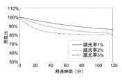
各試験において、照度の変化率が、1%/分、2%/分、5%/分の3パターンが準備された。そして、最も変化率の高い5%/分で照度を変化させた場合において、照度が所定の目標照度値に達するまでの時間である120分が試験時間として設定された。この目標照度値は、初期照度の80%(試験1)、初期照度の60%(試験2)の2パターンが設定された。つまり、試験1及び試験2のそれぞれは、異なる3パターンの照度変化の態様の下で行われた。つまり、試験は各被験者に対して計6回行われた。
In each test, three patterns of illuminance change rate of 1% / min, 2% / min, and 5% / min were prepared. Then, when the illuminance was changed at 5% / min, which has the highest rate of change, 120 minutes, which is the time until the illuminance reaches a predetermined target illuminance value, was set as the test time. Two patterns of this target illuminance value were set: 80% of the initial illuminance (test 1) and 60% of the initial illuminance (test 2). That is, each of
図5Aは、試験1における経時的な照度変化のグラフである。図5Bは、試験2における経時的な照度変化のグラフである。いずれのグラフも、横軸は試験開始からの経過時間を示し、縦軸は初期照度に対する照度の比率を示す。
FIG. 5A is a graph of changes in illuminance over time in
試験1の結果を表1に、試験2の結果を表2に示す。
The results of

試験1によれば、初期照度から80%まで減光した場合、減光率が5%/分以下であれば、全ての被験者が照度変化を認識できなかった。また、試験2によれば、初期照度から60%まで減光した場合、減光率が1%/分、2%/分である場合には全ての被験者が照度変化を認識できず、減光率が5%/分である場合においても1名の被験者のみが照度変化を認識したに留まった。
According to
上記の試験によれば、目標照度値と減光の程度を予め第二情報62に記載しておくことで、オペレータ40が照明領域51における照度の変化を視認できない程度に設定することが可能であることが分かる。なお、第二情報62において、目標照度値は必ずしも記載される必要がなく、減光処理を行う目標処理時間が記載されるものとしても構わない。更に、この目標処理時間が、オペレータ40によって行われることが想定される医療行為の時間よりも長い場合には、第二情報62において目標処理時間が記載されなくても構わない。
According to the above test, by describing the target illuminance value and the degree of dimming in the
第二情報62としては、経過時間と初期照度からの照度比との関係がテーブルの形式で記載されていても構わないし、数式で記載されていても構わない。本実施形態では、電球色のLED素子7aと白色のLED素子7bの両者に対して、同じ態様で減光処理を行うことを想定している。このため、第二情報62としては、電球色のLED素子7aと白色のLED素子7bの両者に共通の情報が記載されている。
As the
別の例として、第二情報62において、経過時間と各LED素子7に対する供給電流量の関係がテーブルの形式で記載されていても構わないし、数式で記載されていても構わない。電球色のLED素子7aと白色のLED素子7bの両者に対して、同じ態様で減光処理を行うとしても、各LED素子(7a、7b)に対する供給電流量の値自体は異なることが想定される。よって、この場合には、第二情報62としては、各LED素子(7a、7b)別に情報が記載される。
As another example, in the
[動作]
オペレータ40は、図3に示すようにヘッドバンド3を頭部に装着し、主電源31をオンにする。制御部11(電流量決定部12)は、主電源31がオン状態になったことを検知すると、記憶部15から第一情報61を読み出して、当該第一情報61に基づいて、初期時点におけるLED素子7に対する電流量を決定する。制御部11(給電部13)は、決定された電流量の電流をケーブル23に出力する。これにより、LED素子7が発光する。このとき、照明領域51には第一情報61に基づいて設定された初期照度が実現されている。
[motion]
The
タイマ16は、初期時点、すなわち本実施形態では、主電源31がオン状態になった時点からの経過時間を測定する。制御部11(電流量決定部12)は、タイマ16から経過時間に関する情報が、逐次、又は所定のタイミングごとに供給される。制御部11(電流量決定部12)は、タイマ16からの経過時間に応じて、記憶部15から第二情報62を読み出して、当該第二情報62に基づいてLED素子7に対する電流量を再決定する。制御部11(給電部13)は、決定された電流量の電流をケーブル23に出力する。これにより、LED素子7の輝度が少し低下し、照明領域51の照度が少し低下する。しかし、上述したように、第二情報62に記載された関係は、照明領域51の照度の低下がオペレータ40によって認識できないように設定されている。このため、オペレータ40は、照度の低下を認識することなく、医療行為を続行することができる。
The
制御部11(電流量決定部12)は、経過時間に応じて上記の処理を続行する。この結果、照明領域51の照度は、時間の経過と共に逓減する。第二情報62において、目標照度値が記載されている場合には、制御部11(電流量決定部12)は、目標照度値に達した時点でLED素子7に対する供給電流量の低下を停止する。また、第二情報62において、減光処理を行う目標処理時間が記載されている場合には、制御部11(電流量決定部12)は、初期時点からの経過時間が目標処理時間に達した時点でLED素子7に対する供給電流量の低下を停止する。
The control unit 11 (current amount determination unit 12) continues the above processing according to the elapsed time. As a result, the illuminance of the
上記の構成によれば、オペレータ40は、照明領域51の照度が逓減していることを認識することなく、患者43に対する医療行為を続行することができる。一方で、実際には、照明領域51の照度は、時間の経過と共に初期時点よりも低下しているため、オペレータ40の目や肩に対する負担を軽減する効果が得られる。
According to the above configuration, the
ところで、オペレータ40によっては、患者43に対する医療行為の実行中において、意図的に術野(照明領域51)の照度を上昇又は低下させたい場合があり得る。本実施形態の医療用ヘッドライト1は、このような事情に鑑み、音声認識機能が実装されている。
By the way, depending on the
音声認識オンオフ切替スイッチ32がオン状態である場合、音声認識インジケータ35はマイク22からの音声信号を受信すると、この音声信号を所定の制御信号に変換して制御部11に出力する。例えば、オペレータ40がマイク22を使って「アップ」と発言すると、音声認識インジケータ35は「アップ」という音声信号を受信し、制御部11に対してLED素子7に対する供給電流量を所定値だけ上昇する旨の指示信号に変換して出力する。制御部11は、当該信号を受信すると、LED素子7に対する供給電流量を前記所定値だけ上昇させる。これにより、照明領域51の照度が上昇する。例えば、オペレータ40が、マイク22を使って「アップ」などの所定の文言を繰り返し発言することで、照度が更に高められるものとすることができる。
When the voice recognition on / off
同様に、例えば、オペレータ40がマイク22を使って「ダウン」と発言することで、制御部11は、LED素子7に対する供給電流量を所定値だけ低下させる。これにより、照明領域51の照度が低下する。例えば、オペレータ40が、マイク22を使って「ダウン」などの所定の文言を繰り返し発言することで、照度が更に低下されるものとすることができる。
Similarly, for example, when the
また、オペレータ40によっては、患者43に対する医療行為の実行中において、意図的に術野(照明領域51)の色温度を上昇又は低下させたい場合があり得る。このような場合にも、音声認識機能を利用することができる。例えば、オペレータ40がマイク22を使って「ホワイト」と発言すると、音声認識インジケータ35は「ホワイト」という音声信号を受信し、制御部11に対して、電球色のLED素子7aの輝度値に対する、白色LED素子7bの輝度値の比率を所定値だけ上昇する旨の指示信号に変換して出力する。制御部11は、当該信号を受信すると、前記輝度値の比率が前記所定値だけ上昇するように、LED素子7(7a,7b)に対する供給電流量を変更する。同様に、例えば、オペレータ40がマイク22を使って「オレンジ」と発言することで、白色LED素子7bの輝度値に対する、電球色のLED素子7aの輝度値の比率が所定値だけ上昇するように、LED素子7(7a,7b)に対する供給電流量を変更する。
Further, depending on the
また、オペレータ40がマイク22を使って「ホワイト」又は「オレンジ」のような所定の文言を繰り返し発言することで、照明領域51の色温度が連続的(断続的)に変化できるものとしても構わない。
Further, the color temperature of the
なお、医療行為中にオペレータ40が行った発言が、誤って音声認識インジケータ35によって認識されてしまい、照明領域51の照明の態様が意図せず変化するおそれも考えられる。このような事態を避ける目的で、音声認識オンオフ切替スイッチ32が設けられている。音声認識オンオフ切替スイッチ32を予めオフにしておくことで、音声認識機能を解除することできる。
It is also possible that the speech made by the
[別実施形態]
以下、別実施形態について説明する。
[Another Embodiment]
Hereinafter, another embodiment will be described.
〈1〉初期段階における視認のしやすさや、視覚的に認識できない程度の照度の低下度合に関しては、個人差が存在する場合がある。このため、第一情報61及び第二情報62は、オペレータ40毎の情報として記憶部15に格納されていても構わない。この場合、記憶部15には、各オペレータ40を識別するためのID情報などに紐付けされた状態で、各第一情報61及び第二情報62が記憶部15に格納されているものとすることができる。
<1> There may be individual differences in the ease of visual recognition in the initial stage and the degree of decrease in illuminance to the extent that it cannot be visually recognized. Therefore, the
また、第一情報61及び第二情報62は、オペレータ40個別の情報ではなく、オペレータ40の年齢、性別といった属性別の情報として記憶部15に格納されていても構わない。
Further, the
このような場合、オペレータ40は、医療用ヘッドライト1の使用開始前に、自己の属性を制御部11に認識させる必要がある。この方法の一例としては、例えばマイク22を通じて、自己の属性に関する情報(ID情報、年齢や性別に関する情報)を入力して、音声認識インジケータ35を通じて制御部11に当該属性に関する情報を出力する方法を採用することができる。別の一例としては、制御ボックス10に不図示の属性入力用操作部を備え、当該操作部を通じて事前にオペレータ40が自己の属性を入力することで、制御部11に当該属性に関する情報を与える方法を採用することができる。
In such a case, the
〈2〉医療用ヘッドライト1が、制御部11によって第二情報62に基づく減光処理(自動制御発光)を行うか否かを事前に設定できるものとしても構わない。この場合、減光処理を開始する指示が制御部11に出力された時点が、上記「初期時点」に対応する。
<2> The
この方法の一例としては、制御ボックス10に不図示の減光制御オンオフ切替スイッチを備えておき、減光処理を行いたくない場合には、このスイッチを「オフ」にする方法を採用することができる。制御部11は、減光制御オンオフ切替スイッチが「オフ」になっている場合には、第二情報62に基づく減光処理を行わず、同スイッチが「オン」になった時点から減光処理を実行する。
As an example of this method, the
別の方法の一例として、オペレータ40がマイク22を通じて、減光制御をオフ/オンにする旨の音声信号を発することで、音声認識インジケータ25が、上記減光制御オンオフ切替スイッチと同様の機能を実現するものとしても構わない。
As an example of another method, the
〈3〉上述した医療用ヘッドライト1の構造はあくまで一例であり、種々の変更が可能である。具体的には以下の通りである。
<3> The structure of the
図1では、本体部5は、4個のLED素子7からなる発光面を複数備え、それぞれの発光面が段差を有して配置されているかのように図示されている。しかし、この態様は一例である。例えば、本体部5に備えられた全ての複数のLED素子7が、同一平面又は同一曲面上に配置されていても構わない。
In FIG. 1, the
本体部5において、LED素子7の裏面側にフィン9を設けるか否かは任意である。医療用ヘッドライト1がフェースガード21を備えるか否かは任意である。バッテリーボックス25が、残量表示モニタ28及び残量警告スピーカ29を備えるか否かは任意である。制御ボックス10がバックアンサースピーカ35を備えるか否かは任意である。
Whether or not the
医療用ヘッドライト1は、バッテリーボックス25を備えず、商用電源から電力が供給されることで駆動する構成とすることも可能である。
The
ヘッドバンド3と本体部5とを連結するための固定部4は、3箇所以上に設けられていても構わない。
The fixing
〈4〉上記実施形態では、医療用ヘッドライト1が音声認識機能を有している場合を想定して説明した。しかし、医療用ヘッドライト1が音声認識機能を備えないものとしても構わない。
<4> In the above embodiment, the case where the
1 : 医療用ヘッドライト
3 : ヘッドバンド
4 : 固定部
5 : 本体部
7 : LED素子
7a : 電球色LED素子
7b : 白色LED素子
8 : 角度調整用ツマミ
9 : フィン
10 : 制御ボックス
11 : 制御部
12 : 電流量決定部
13 : 給電部
16 : タイマ
21 : フェースガード
22 : マイク
23 : ケーブル
25 : バッテリーボックス
26 : 充電用コネクタ
27 : バッテリーケーブル
28 : 残量表示部
29 : 残量警告スピーカ
31 : 主電源
32 : 音声認識オンオフ切替スイッチ
33 : 調光用ツマミ
33a : 電球色調光用ツマミ
33b : 白色調光用ツマミ
35 : 音声認識インジケータ
36 : 音声認識アンサーバックスピーカ
40 : オペレータ
41 : 載置台
43 : 患者
50 : 光束
51 : 照明領域
1: Medical headlight 3: Headband 4: Fixed part 5: Main body part 7:
Claims (6)
前記ヘッドバンドよりも外側に位置した状態で、前記ヘッドバンドの少なくとも2箇所に設けられた固定部に対して連結されており、LED素子が実装された、本体部と、
前記LED素子に対して給電制御を行う制御部と、
前記制御部に対する通電のオンオフを制御する主電源と、
前記LED素子が時間の経過と共に発光強度を逓減する旨の自動制御発光を開始する初期時点の前記LED素子への供給電流量に関する第一情報、及び、前記初期時点からの経過時間と前記LED素子への供給電流量との関係に関する第二情報が格納された記憶部と、
前記初期時点からの経過時間を計測する時間計測部とを備え、
前記初期時点は、前記主電源がオンになった時点又は前記自動制御発光の開始の指示が外部から前記制御部に対して入力された時点であり、
前記第二情報には、前記オペレータが照度の変化を視覚的に認識できない範囲内で時間の経過と共に前記LED素子への供給電流量が逓減する関係が記載されており、
前記制御部は、
前記自動制御発光を開始する旨の指示信号が入力されると、前記記憶部に格納された前記第一情報に基づいて前記LED素子への供給電流量を決定すると共に、当該決定された量の電流を前記LED素子に供給し、
前記時間計測部から入力される前記初期時点からの経過時間に応じて、前記記憶部に格納された前記第二情報に基づいて前記LED素子への供給電流量を決定すると共に、当該決定された量の電流を前記LED素子に供給することを特徴とする医療用ヘッドライト。 A curved headband that can be worn on the operator's head,
In a state of being located outside the headband, the main body portion, which is connected to at least two fixed portions of the headband and has an LED element mounted on the headband,
A control unit that controls power supply to the LED element,
A main power supply that controls the on / off of energization of the control unit,
First information regarding the amount of current supplied to the LED element at the initial time when the LED element starts automatic control light emission to the effect that the light emission intensity gradually decreases with the passage of time, and the elapsed time from the initial time and the LED element. A storage unit that stores the second information regarding the relationship with the amount of current supplied to
It is equipped with a time measuring unit that measures the elapsed time from the initial time point.
The initial time point is a time when the main power is turned on or a time when an instruction to start the automatic control light emission is input to the control unit from the outside.
The second information describes a relationship in which the amount of current supplied to the LED element gradually decreases with the passage of time within a range in which the operator cannot visually recognize the change in illuminance.
The control unit
When the instruction signal to start the automatic control light emission is input, the amount of current supplied to the LED element is determined based on the first information stored in the storage unit, and the determined amount is determined. A current is supplied to the LED element to supply the current.
The amount of current supplied to the LED element is determined based on the second information stored in the storage unit according to the elapsed time from the initial time point input from the time measurement unit, and the determination is made. A medical headlight characterized by supplying a large amount of electric current to the LED element.
前記第一情報には、前記第一LED素子及び前記第二LED素子それぞれへの供給電流量が記載されており、
前記第二情報には、前記初期時点からの経過時間と前記第一LED素子及び前記第二LED素子それぞれに対する供給電流量との関係が記載されているか、又は、前記初期時点からの経過時間と前記初期時点における供給電流量に対する相対値との関係が記載されていることを特徴とする請求項1に記載の医療用ヘッドライト。 The main body includes a plurality of first LED elements showing the first color temperature and a plurality of second LED elements showing a second color temperature different from the first color temperature.
The first information describes the amount of current supplied to each of the first LED element and the second LED element.
The second information describes the relationship between the elapsed time from the initial time point and the amount of current supplied to each of the first LED element and the second LED element, or the elapsed time from the initial time point. The medical headlight according to claim 1, wherein the relationship with the relative value with respect to the supply current amount at the initial time point is described.
前記制御部は、前記オペレータの前記属性に関する情報が入力されると、前記記憶部から、当該オペレータの前記属性に対応した前記第一情報及び前記第二情報を読み出し、当該読み出された情報に基づいて前記LED素子への供給電流量を決定することを特徴とする請求項1〜3のいずれか1項に記載の医療用ヘッドライト。 The storage unit stores the first information and the second information for each attribute of the operator.
When the information regarding the attribute of the operator is input, the control unit reads the first information and the second information corresponding to the attribute of the operator from the storage unit, and uses the read information as the read information. The medical headlight according to any one of claims 1 to 3, wherein the amount of current supplied to the LED element is determined based on the above.
前記制御部は、前記制御情報入力部から、照度の上昇又は低下に関する指示情報が与えられると、前記第一情報及び前記第二情報に基づいて決定された前記LED素子への供給電流量に対して、所定の値だけ増加又は減少させた量の電流を前記LED素子に供給することを特徴とする請求項1〜4のいずれか1項に記載の医療用ヘッドライト。 A control information input unit configured to be input by the operator is provided.
When the control information input unit gives instruction information regarding an increase or decrease in illuminance, the control unit receives the amount of current supplied to the LED element determined based on the first information and the second information. The medical headlight according to any one of claims 1 to 4, wherein an amount of electric current increased or decreased by a predetermined value is supplied to the LED element.
前記制御部は、前記音声認識部から、照度の上昇又は低下に関する指示信号が与えられると、前記第一情報及び前記第二情報に基づいて決定された前記LED素子への供給電流量に対して、所定の値だけ増加又は減少させた量の電流を前記LED素子に供給することを特徴とする請求項1〜5のいずれか1項に記載の医療用ヘッドライト。 A voice recognition unit that outputs an instruction signal corresponding to the voice signal to the control unit when receiving a predetermined voice signal is provided.
When an instruction signal regarding an increase or decrease in illuminance is given from the voice recognition unit, the control unit receives a supply current amount to the LED element determined based on the first information and the second information. The medical headlight according to any one of claims 1 to 5, wherein an amount of electric current increased or decreased by a predetermined value is supplied to the LED element.
Priority Applications (1)
| Application Number | Priority Date | Filing Date | Title |
|---|---|---|---|
| JP2017058222A JP6895659B2 (en) | 2017-03-23 | 2017-03-23 | Medical headlights |
Applications Claiming Priority (1)
| Application Number | Priority Date | Filing Date | Title |
|---|---|---|---|
| JP2017058222A JP6895659B2 (en) | 2017-03-23 | 2017-03-23 | Medical headlights |
Publications (2)
| Publication Number | Publication Date |
|---|---|
| JP2018158041A JP2018158041A (en) | 2018-10-11 |
| JP6895659B2 true JP6895659B2 (en) | 2021-06-30 |
Family
ID=63796048
Family Applications (1)
| Application Number | Title | Priority Date | Filing Date |
|---|---|---|---|
| JP2017058222A Active JP6895659B2 (en) | 2017-03-23 | 2017-03-23 | Medical headlights |
Country Status (1)
| Country | Link |
|---|---|
| JP (1) | JP6895659B2 (en) |
Families Citing this family (1)
| Publication number | Priority date | Publication date | Assignee | Title |
|---|---|---|---|---|
| JP7329994B2 (en) * | 2019-07-05 | 2023-08-21 | 富士フイルムヘルスケア株式会社 | X-ray diagnostic equipment |
Family Cites Families (6)
| Publication number | Priority date | Publication date | Assignee | Title |
|---|---|---|---|---|
| US20040264193A1 (en) * | 2001-08-23 | 2004-12-30 | Yukiyasu Okumura | Color temperature-regulable led light |
| DE102005036275A1 (en) * | 2005-08-02 | 2007-02-08 | Berchtold Holding Gmbh | surgical light |
| US9062833B2 (en) * | 2011-12-06 | 2015-06-23 | Acp Japan Co., Ltd. | Medical light source device |
| JP5393931B2 (en) * | 2011-12-08 | 2014-01-22 | オリンパスメディカルシステムズ株式会社 | Endoscope light source device and method for controlling endoscope light source device |
| WO2013173258A1 (en) * | 2012-05-15 | 2013-11-21 | The Cleveland Clinic Foundation | Integrated surgical task lighting |
| JP6125937B2 (en) * | 2013-07-19 | 2017-05-10 | 合同会社ジャパン・メディカル・クリエーティブ | Frame light type surgical light |
-
2017
- 2017-03-23 JP JP2017058222A patent/JP6895659B2/en active Active
Also Published As
| Publication number | Publication date |
|---|---|
| JP2018158041A (en) | 2018-10-11 |
Similar Documents
| Publication | Publication Date | Title |
|---|---|---|
| US6902290B2 (en) | Finger-mounted light for variable light output | |
| US8172834B2 (en) | Portable handheld illumination system | |
| CN107923606B (en) | Operating lamp with brightness adjustment | |
| US20050099824A1 (en) | Methods and systems for medical lighting | |
| KR101547360B1 (en) | Medical surgery room with coloured lighting | |
| US20090016075A1 (en) | Semiconductor lighting in console system for illuminating biological tissues | |
| JP2009544422A (en) | Smart connector system for surgical machines | |
| JP2013514137A (en) | Photonic lattice LED for eyeball illumination | |
| EP2654893B1 (en) | Light therapy device | |
| US8308333B2 (en) | Surgical lamp with illuminated handles | |
| JP2007044251A (en) | Endoscope apparatus | |
| JP6895659B2 (en) | Medical headlights | |
| JP3124676U (en) | Auxiliary illuminator for slit lamp microscope | |
| JP5097925B2 (en) | Simple estimation method and measurement system for spectral sensitivity characteristics of human eye | |
| JP2006288965A (en) | Photo-therapeutic device | |
| US20170020625A1 (en) | Replaceable light source and radiation generating device including the same | |
| JP6847416B2 (en) | Medical headlights | |
| JP2007044245A (en) | Endoscope apparatus | |
| WO2018007285A1 (en) | An apparatus for providing semantic information and a method of operating the same | |
| JP2019000476A5 (en) | ||
| KR101918085B1 (en) | Lighting for hospital | |
| CN109951917B (en) | Control device, lighting device, and control method | |
| KR20200098973A (en) | Portable headlight for medical treatment | |
| KR102574519B1 (en) | Lighting device for medical treatment and lighting system | |
| JP4272018B2 (en) | Mode display device for medical lighting |
Legal Events
| Date | Code | Title | Description |
|---|---|---|---|
| RD01 | Notification of change of attorney |
Free format text: JAPANESE INTERMEDIATE CODE: A7426 Effective date: 20170719 |
|
| A521 | Written amendment |
Free format text: JAPANESE INTERMEDIATE CODE: A821 Effective date: 20170719 |
|
| A621 | Written request for application examination |
Free format text: JAPANESE INTERMEDIATE CODE: A621 Effective date: 20200319 |
|
| A711 | Notification of change in applicant |
Free format text: JAPANESE INTERMEDIATE CODE: A711 Effective date: 20200319 |
|
| A521 | Written amendment |
Free format text: JAPANESE INTERMEDIATE CODE: A821 Effective date: 20200319 |
|
| A977 | Report on retrieval |
Free format text: JAPANESE INTERMEDIATE CODE: A971007 Effective date: 20210217 |
|
| A131 | Notification of reasons for refusal |
Free format text: JAPANESE INTERMEDIATE CODE: A131 Effective date: 20210225 |
|
| A521 | Written amendment |
Free format text: JAPANESE INTERMEDIATE CODE: A523 Effective date: 20210420 |
|
| TRDD | Decision of grant or rejection written | ||
| A01 | Written decision to grant a patent or to grant a registration (utility model) |
Free format text: JAPANESE INTERMEDIATE CODE: A01 Effective date: 20210514 |
|
| A61 | First payment of annual fees (during grant procedure) |
Free format text: JAPANESE INTERMEDIATE CODE: A61 Effective date: 20210528 |
|
| R150 | Certificate of patent or registration of utility model |
Ref document number: 6895659 Country of ref document: JP Free format text: JAPANESE INTERMEDIATE CODE: R150 |