JP6895111B2 - Vehicle travel control device - Google Patents
Vehicle travel control device Download PDFInfo
- Publication number
- JP6895111B2 JP6895111B2 JP2017057964A JP2017057964A JP6895111B2 JP 6895111 B2 JP6895111 B2 JP 6895111B2 JP 2017057964 A JP2017057964 A JP 2017057964A JP 2017057964 A JP2017057964 A JP 2017057964A JP 6895111 B2 JP6895111 B2 JP 6895111B2
- Authority
- JP
- Japan
- Prior art keywords
- lane
- vehicle
- change
- lane change
- predetermined distance
- Prior art date
- Legal status (The legal status is an assumption and is not a legal conclusion. Google has not performed a legal analysis and makes no representation as to the accuracy of the status listed.)
- Active
Links
Images


Description
本発明は、車両の走行制御装置に関し、さらに詳しくは、自動車線変更機能を備えた車両の走行制御装置に関する。 The present invention relates to a vehicle travel control device, and more particularly to a vehicle travel control device having a lane change function.
運転者の負担軽減を目的として、従来運転者が行っていた認知・判断・操作を部分的に車両が行うようにする種々の技術、例えば、ACC(アダプティブクルーズコントロール)、LKA(レーンキーピングアシスト)などが実用化されている。さらに、ACCによる追従走行中において、先行車の速度が自車の設定速度に比べて低い場合に、自動操縦により車線変更を実施する技術も開発されている。 For the purpose of reducing the burden on the driver, various technologies that allow the vehicle to partially perform the recognition, judgment, and operation that were conventionally performed by the driver, such as ACC (Adaptive Cruise Control) and LKA (Lane Keeping Assist). Etc. have been put into practical use. Further, a technique has been developed for automatically maneuvering to change lanes when the speed of the preceding vehicle is lower than the set speed of the own vehicle during follow-up traveling by ACC.
例えば、特許文献1には、周辺環境情報と走行情報とに基づいて自車両の走行車線前方の追い越し対象とする追い越し対象車両を検出し、周辺環境情報に基づいて自車両の走行車線後方の後続車両を元車線後続車両として検出し、追い越し対象車両と元車線後続車両とを監視し、該監視結果に基づいて追い越し対象車両に対する追い越し走行を可変制御することが記載されている。
For example, in
ところで、自動操縦による車線変更が実施可能と判断された場合であっても、他車両の走行状態の急激な変化などにより、車線変更を中止した方が良い場合もあり得る。しかしながら、特許文献1では、車線変更を中止する判断基準を、自車両に対する後続車両の相対速度または後続車両の車線変更意思に依拠しており、自車位置は考慮されないため、ほぼ車線変更が完了しているにも拘わらず、車線変更を中止して逆操舵により元車線に復帰するようなケースも想定され、交通流への影響や乗員への不快感を与える車両挙動を生じさせる懸念があった。
By the way, even if it is determined that the lane change can be carried out by autopilot, it may be better to stop the lane change due to a sudden change in the traveling state of another vehicle or the like. However, in
本発明は、上記のような実状に鑑みてなされたものであり、その目的は、自動車線変更中に他車両の挙動により車線変更を中止する場合における車両挙動や交通流への影響を低減できる車両の走行制御装置を提供することにある。 The present invention has been made in view of the above circumstances, and an object of the present invention is to reduce the influence on the vehicle behavior and the traffic flow when the lane change is stopped due to the behavior of another vehicle during the lane change. The purpose is to provide a vehicle travel control device.
上記課題を解決するために、本発明は、
外界センサの情報から自車線と隣接車線の区分線および各車線上の他車を認識する周囲認識機能と、内界センサの情報から自車の状態を取得する機能を含む環境状態推定部と、
前記環境状態推定部に取得される情報に基づいて自動車線変更のための目標経路を生成する経路生成部と、
前記目標経路に自車を追従させるべく速度制御および操舵制御を行う車両制御部と、
を備え、先行他車を避けるために隣接車線への自動車線変更を実施可能な車両の走行制御装置において、
前記自動車線変更の実施中に、自車の前方所定距離と後方所定距離と側方所定距離とによって画定される所定領域内に他車が認識された場合に、前記隣接車線との区分線に対する自車の位置により車線変更を継続するか否かを判定する車線変更継続可否判定手段と、該車線変更継続可否判定手段により車線変更を継続すべきでないと判定された場合に、元車線に復帰すべく前記目標経路を再生成する機能を備え、
前記車線変更継続可否判定手段は、車線変更を継続すべきと判定された場合に、前記前方所定距離、前記後方所定距離、前記側方所定距離よりそれぞれ小さく、かつ、自車の最小前方所定距離、最小後方所定距離、最小側方所定距離と同じかまたはそれより大きい第2の前方所定距離、後方所定距離、側方所定距離によって画定される第2の所定領域内に他車が認識された場合には、元車線に復帰すべく前記目標経路を再生成するように構成されていることを特徴とする。
In order to solve the above problems, the present invention
An environmental state estimation unit that includes a peripheral recognition function that recognizes the dividing line between the own lane and the adjacent lane and other vehicles on each lane from the information of the outside world sensor, and a function of acquiring the state of the own vehicle from the information of the inside world sensor.
A route generation unit that generates a target route for changing the lane based on the information acquired by the environmental state estimation unit, and a route generation unit.
A vehicle control unit that performs speed control and steering control so that the vehicle follows the target route.
In the driving control device of a vehicle that can change lanes to an adjacent lane in order to avoid other vehicles in front of the vehicle.
When another vehicle is recognized within a predetermined area defined by a predetermined distance in front, a predetermined distance behind, and a predetermined distance to the side of the own vehicle during the implementation of the lane change, the division line with the adjacent lane is used. Return to the original lane when it is determined by the lane change continuation possibility determination means that determines whether or not to continue the lane change depending on the position of the own vehicle and the lane change continuation continuation determination means that the lane change should not be continued. It has a function to regenerate the target route .
When it is determined that the lane change should be continued, the lane change continuation determination means is smaller than the front predetermined distance, the rear predetermined distance, and the side predetermined distance, respectively, and is the minimum forward predetermined distance of the own vehicle. , Another vehicle is recognized within the second predetermined area defined by the second predetermined distance in front, the predetermined distance behind, and the predetermined side distance, which are the same as or larger than the minimum rear predetermined distance and the minimum lateral predetermined distance. In some cases, it is characterized in that it is configured to regenerate the target route in order to return to the original lane.
本発明に係る車両の走行制御装置によれば、自動車線変更の実施中に所定領域に侵入する他車が認識された場合に、自車の位置に基づいて車線変更継続可否を判定し、車線変更の継続または中止を行うので、隣接車線への車線変更がほぼ完了した状態で車線変更を中止して元車線に戻る場合のような不自然な車両挙動を回避でき、交通流や乗員への影響を低減するうえで有利である。 According to the vehicle travel control device according to the present invention, when another vehicle invading a predetermined area is recognized during the lane change, it is determined whether or not the lane change can be continued based on the position of the own vehicle, and the lane is changed. Since the change is continued or canceled, it is possible to avoid unnatural vehicle behavior such as when the lane change to the adjacent lane is almost completed and the lane change is stopped and the vehicle returns to the original lane. It is advantageous in reducing the impact.
以下、本発明の実施形態について、図面を参照しながら詳細に説明する。
図1において、本発明に係る走行制御システムを備えた車両1は、エンジンや車体など一般的な自動車の構成要素に加え、従来運転者が行っていた認知・判断・操作を車両側で行うために、車両周囲環境を検知する外界センサ21、車両情報を検知する内界センサ22、速度制御および操舵制御のためのコントローラ/アクチュエータ群、定速走行/追従走行制御のためのACCコントローラ14、および、自動車線変更(経路追従制御)を実施するための自動運転コントローラ10を備えている。
Hereinafter, embodiments of the present invention will be described in detail with reference to the drawings.
In FIG. 1, in the
速度制御および操舵制御のためのコントローラ/アクチュエータ群は、操舵制御のためのEPS(電動パワーステアリング)コントローラ31、加減速度制御のためのエンジンコントローラ32、ESP(登録商標;スタビリティコントロールシステム)/ABS(アンチロックブレーキシステム)コントローラ33を含む。
The controller / actuator group for speed control and steering control includes EPS (electric power steering)
外界センサ21は、自車線51および隣接車線52を画定する道路上の区分線5、自車周辺にある他車両や障害物、人物などの存在と相対距離を画像データや点群データとして自動運転コントローラ10に入力するための複数の検知手段からなる。
The
例えば、図2に示すように、車両1は、前方検知手段211,212としてミリ波レーダ(211)およびカメラ(212)、前側方検知手段213および後側方検知手段214としてLIDAR(レーザ画像検出/測距)、後方検知手段215としてカメラ(バックカメラ)を備え、自車両周囲360度をカバーし、それぞれ自車前後左右方向所定距離内の車両や障害物等の位置と距離、区分線位置を検知できるようにしている。
For example, as shown in FIG. 2, the
内界センサ22は、車速センサ、ヨーレートセンサ、加速度センサなど、車両の運動状態を表す物理量を計測する複数の検知手段からなり、図3に示すように、それぞれの測定値は、自動運転コントローラ10に入力され、外界センサ21からの入力とともに演算処理される。
The
自動運転コントローラ10は、環境・状態推定部11、経路生成部12、および、車両制御部13を含み、以下に記載されるような機能を実施するためのコンピュータ、すなわち、プログラム及びデータを記憶したROM、演算処理を行うCPU、前記プログラム及びデータを読出し、動的データや演算処理結果を記憶するRAM、および、入出力インターフェースなどで構成されている。
The
環境・状態推定部11は、GPS等の測位手段24を用いて自車の絶対位置を取得し、外界センサ21に取得される画像データや点群データなどの外界データに基づいて自車線51および隣接車線52の区分線位置、他車位置および速度を推定する。また、内界センサ22に取得される内界データより自車の運動状態を取得する。
The environment /
経路生成部12は、地図情報23を参照し、環境・状態推定部11で推定された自車位置と、隣接車線52の区分線位置、他車位置および速度と、内界センサ22により検知される自車の運動状態に基づいて、車線変更における自車位置から到達目標地点までの目標経路50を生成する。
The
車両制御部13は、目標経路50に基づいて目標車速および目標舵角を算出し、車速指令をACCコントローラ14に送信し、経路追従のための舵角指令をEPSコントローラ31に送信する。
The
なお、車速は、EPSコントローラ31およびACCコントローラ14にも入力される。車速により操舵トルクが変わるため、EPSコントローラ31は、車速毎の操舵角−操舵トルクマップを参照して操舵機構41にトルク指令を送信する。エンジンコントローラ32、ESP/ABSコントローラ33、EPSコントローラ31により、エンジン42、ブレーキ43、操舵機構41を制御することで、車両1の縦横方向の運動が制御される。
The vehicle speed is also input to the
(自動車線変更機能の概要)
次に、中央分離帯のある片側二車線以上の高速道路で、先行車を追い越すための車線変更を想定して、自動車線変更機能の概要を説明する。
(Overview of lane change function)
Next, an outline of the lane change function will be described assuming a lane change for overtaking a preceding vehicle on an expressway having two or more lanes on each side with a median strip.
自動運転コントローラ10(経路生成部12)は、外界センサ21を通じて環境・状態推定部11に取得される外界情報(車線、自車位置、自車走行車線および隣接車線を走行中の他車位置、速度)、および、内界センサ22に取得される内界情報(車速、ヨーレート、加速度)に基づいて、車線変更の目標経路および目標車速を生成する。そして、生成した目標経路・目標車速による他車両との車間距離・相対速度に基づいて、車線変更が可能か否かを判定し、車線変更可能と判定された場合は「自動車線変更可能フラグ」を立てる。
The automatic driving controller 10 (route generation unit 12) has external world information (lane, own vehicle position, own vehicle traveling lane, and other vehicle position traveling in the adjacent lane) acquired by the environment /
自動車線変更機能が起動状態で「自動車線変更可能フラグ」が立っており、さらに、運転者の車線変更意思(ウインカ操作等)があった場合のみ、自動運転コントローラ10が生成した目標経路に従って自動操舵により車線変更が実行される。
Only when the lane change function is activated and the "lane changeable flag" is set and the driver has an intention to change lanes (winker operation, etc.), the
自動運転コントローラ10は、自車位置と自車の運動特性、すなわち、車速Vで走行中に操舵機構41に操舵トルクTが与えられた時に生じる前輪舵角δによって、車両運動により生じるヨーレートと横加速度の関係から、Δt秒後の車両の速度・姿勢・横変位を推定し、Δt秒後に横変位がytとなるような舵角指令をEPSコントローラ31に与え、Δt秒後に速度Vtとなるような速度指令をACCコントローラ14に与える。
The
車線変更の終了は、自車位置が隣接車線の中央(xc±α,yc±β;α・βは許容誤差)にあり、かつ、追い越した車両との車間距離が、自車速と後方車速により決定される後方所定距離より大きいことをもって判断される。後方所定距離については後述する。 At the end of the lane change, the position of the own vehicle is in the center of the adjacent lane (xc ± α, yc ± β; α and β are margins of error), and the distance between the overtaking vehicle and the vehicle depends on the own vehicle speed and the rear vehicle speed. It is judged that it is larger than the determined rearward predetermined distance. The rear predetermined distance will be described later.
(ACC、EPS、ESP/ABS、エンジン制御と自動車線変更機能の関係)
自動車線変更機能は、主としてACCコントローラ14による縦方向制御(速度制御)とEPSコントローラ31による横方向制御(操舵制御)を組み合わせることにより実施される。ACCコントローラ14、EPSコントローラ31、エンジンコントローラ32、および、ESP/ABSコントローラ33は、自動操舵とは無関係に独立して作動するが、自動車線変更機能の作動中は、自動運転コントローラ10からの指令入力でも作動可能になっている。
(Relationship between ACC, EPS, ESP / ABS, engine control and lane change function)
The lane change function is mainly carried out by combining vertical control (speed control) by the
自動運転コントローラ10からの舵角指令を受けたEPSコントローラ31は、車速−操舵角−操舵トルクのマップを参照して、アクチュエータ(EPSモータ)にトルク指令を出し、操舵機構41が目標とする前輪舵角を与える。また、自動運転コントローラ10からの速度指令を受けたACCコントローラ14は、内界センサ22から取得される車速に応じてブレーキ制御のための減速指令またはエンジン制御のための加減速指令を出す。
Upon receiving the steering angle command from the
ACCコントローラ14からの減速指令を受けたESP/ABSコントローラ33は、アクチュエータに油圧指令を出し、ブレーキ43の制動力を制御することで車速を制御する。また、ACCコントローラ14からの加減速指令を受けたエンジンコントローラ32は、アクチュエータ出力(スロットル開度)を制御することで、エンジン42にトルク指令を与え、駆動力を制御することで車速を制御する。
The ESP /
ACC機能は、外界センサ21としてのミリ波レーダ211、ACCコントローラ14、エンジンコントローラ32、ESP/ABSコントローラ33等のハードウエアとソフトウエアの組合せで機能する。
The ACC function functions by combining hardware and software such as a
すなわち、先行車が無い場合は目標車速(クルーズコントロールセット速度)で定速走行し、先行車に追いついた場合(先行車速度が目標車速以下の場合)には、先行車速度に合わせて、設定されたタイムギャップ(車間時間=車間距離/自車速)に応じた車間距離を維持しながら先行車に追従走行する。 That is, if there is no preceding vehicle, the vehicle runs at a constant speed at the target vehicle speed (cruise control set speed), and if it catches up with the preceding vehicle (when the preceding vehicle speed is less than or equal to the target vehicle speed), it is set according to the preceding vehicle speed. It follows the preceding vehicle while maintaining the inter-vehicle distance according to the set time gap (inter-vehicle time = inter-vehicle distance / own vehicle speed).
なお、EPSコントローラ31による操舵制御を利用した機能としてLKA(レーンキーピングアシスト)がある。LKAは、外界センサ21(カメラ212,215)に取得される画像データに基づき、自動運転コントローラ10の環境・状態推定部11で車線区分線と自車位置を検知し、車線中央を走行できるように、EPSコントローラ31により操舵力を補助するものであり、自動操舵を行うものではない。
LKA (lane keeping assist) is a function that utilizes steering control by the
したがって、ACCと連動してLKA機能が作動している状況から自動車線変更に移行する場合、「自動車線変更可能フラグ」が立った状態で運転者の車線変更意思(ウインカ点滅)があった時点でLKA機能が解除され、自動車線変更が開始される。自動車線変更終了後はLKA機能が再作動し、LKA機能と連動したACC走行に戻る。 Therefore, when shifting from the situation where the LKA function is operating in conjunction with ACC to changing lanes, when the driver has the intention to change lanes (blinking blinker) with the "lane changeable flag" set. The LKA function is canceled and the lane change is started. After the lane change is completed, the LKA function is restarted and the vehicle returns to ACC driving linked with the LKA function.
(車線変更中の周囲環境変化)
ところで、既に述べたように、自車周囲環境および目標経路が確認され、「自動車線変更可能フラグ」が立った状態で、運転者の車線変更意思(ウインカ操作等)があった場合にのみ、自動車線変更が開始されるが、車線変更を開始し隣接車線に移動するまでの間に、他車両の挙動により周囲環境が変化する可能性もある。
(Changes in the surrounding environment while changing lanes)
By the way, as already mentioned, only when the driver's lane change intention (winker operation, etc.) is made while the surrounding environment of the vehicle and the target route are confirmed and the "lane changeable flag" is set. The lane change is started, but the surrounding environment may change depending on the behavior of other vehicles before the lane change is started and the vehicle moves to the adjacent lane.
例えば、図6(a)に示すように、合流車線54から進入しようとする他車2′を避けるために、自車線(左側車線)51から隣接車線(中央車線)52に自動車線変更中に、追越車線(右側車線)53を走行していた他車3が隣接車線52に車線変更し、自車1の右側方所定距離内に入ってきた場合や、図6(b)に示すように、先行他車2を追い越すために、自車線(中央車線)52から追越車線53に自動車線変更中に、先行他車2も追越車線53に車線変更を開始し、自車1′の右前側方所定距離内に入ってきた場合である。このような車線変更中の周囲環境変化に対し、以下のような問題が想定される。
For example, as shown in FIG. 6A, while changing lanes from the own lane (left lane) 51 to the adjacent lane (center lane) 52 in order to avoid another vehicle 2'trying to enter from the merging
自動車線変更継続可否の判断基準が、自車の目標経路上の他車両の存在または元車線復帰後の他車両との車間距離、あるいは、自車両に対する後続車両の相対速度または後続車両の車線変更意思(ウインカ点滅)である場合、現在の自車位置は考慮されない。このため、既に自車両の前後両輪が目標車線(隣接車線)と元車線の区分線よりも目標車線側にある状態、つまり隣接車線への移行がほぼ終了した状態で車線変更を中止して元車線に戻るようなケースも想定され、このような車両挙動は、車線変更意思(ウインカ点滅)を示したとしても、後続車両にとっては挙動不審に映る。 The criteria for determining whether or not to continue changing lanes are the presence of another vehicle on the target route of the own vehicle, the distance between the vehicle and the other vehicle after returning to the original lane, the relative speed of the following vehicle to the own vehicle, or the lane change of the following vehicle. If it is intention (blinking blinker), the current position of the vehicle is not taken into consideration. For this reason, the lane change is stopped when the front and rear wheels of the own vehicle are already on the target lane side of the target lane (adjacent lane) and the dividing lane of the original lane, that is, the transition to the adjacent lane is almost completed. It is assumed that the vehicle will return to the lane, and even if the vehicle behavior indicates an intention to change lanes (blinking blinkers), the behavior will appear suspicious to the following vehicle.
また、上記ケースでは、車線変更開始〜中止〜元車線に戻るまでの所要時間が、車線変更をそのまま継続した場合に比べて単純計算で2倍程度になる。仮に、自車両の前後両輪が元車線内にある位置で車線変更を中止する場合であれば、小さい操舵角で元の走路に復帰できるが、前後両輪が区分線を越え隣接車線への移行がほぼ終了した状態で車線変更を中止して元車線に戻るようなケースでは、逆操舵による車両の横加速度変化が大きくなり、乗員に不快感を与える虞がある。そこで、自動車線変更中における車線変更継続可否判定を以下のように実施する。 Further, in the above case, the time required from the start to the stop of the lane change to the return to the original lane is about twice as long as the case where the lane change is continued as it is by simple calculation. If the front and rear wheels of the own vehicle are in the original lane and the lane change is stopped, the vehicle can return to the original lane with a small steering angle, but the front and rear wheels cross the dividing line and move to the adjacent lane. In the case where the lane change is stopped and the vehicle returns to the original lane when the vehicle is almost finished, the change in the lateral acceleration of the vehicle due to the reverse steering becomes large, which may cause discomfort to the occupants. Therefore, it is determined whether or not the lane change can be continued during the lane change as follows.
(車線変更継続可否判定)
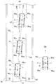
自動車線変更中、自動運転コントローラ10(環境・状態推定部11)は、外界センサ21により自車周囲の車線区分線を認識し、図7に示すように、車線変更前に走行していた車線51の区分線5s,5cと、経路生成により車線変更後に移行する予定の隣接車線52の区分線5c,5dと、自車左右前後輪の接地面中心点WFL,WFR,WRL,WRRの相対位置(車両重心Gのxy座標中心を原点とする前後輪接地面中心点WFL,WFR,WRL,WRRの相対座標)を推定し、常時監視している。
(Judgment whether to continue changing lanes)
During the lane change, the automatic driving controller 10 (environment / state estimation unit 11) recognizes the lane dividing line around the own vehicle by the
そして、自車の運動状態に応じて画定される「所定距離」内への他車の侵入(車線変更等)が検知された場合(環境・状態推定部11に認識される他車が「所定距離」内に侵入すると判断される場合)、自動運転コントローラ10(経路生成部12)は、車線変更前に走行していた車線(51)の右側区分線5c(元車線51側エッジ)と、自車前後輪の接地面中心点(WFL,WFR,WRL,WRR)の相対位置に基づき、次のように車線変更継続可否判定を行う。
Then, when the intrusion of another vehicle (lane change, etc.) into the "predetermined distance" defined according to the movement state of the own vehicle is detected (the other vehicle recognized by the environment /
(i)下記の場合は車線変更を中止し元車線に復帰する。
(a)前輪・後輪接地面中心が全て車線区分線端よりも元車線側にある。
(b)変更先側前輪接地面中心のみが車線区分線端より変更先車線側にある。
(c)変更先側前後輪接地面中心のみが車線区分線端より変更先車線側にある。
(I) In the following cases, the lane change is stopped and the vehicle returns to the original lane.
(A) The center of the front and rear wheel contact patches are all on the original lane side of the lane dividing line end.
(B) Only the center of the front wheel contact patch on the change destination side is on the change destination lane side from the end of the lane dividing line.
(C) Only the center of the front and rear wheel contact patches on the change destination side is on the change destination lane side from the lane division line end.
(ii)下記の場合は車線変更を継続する。
(d)変更先側前後輪と変更元側前輪の接地面中心が車線区分線端より変更先車線側にある(左右前車輪と変更先側後輪の接地面中心が車線区分線端より変更先車線側にある、すなわち、変更元側後輪の接地面中心のみが車線区分線端より変更元車線側にある)。
(e)前輪・後輪接地面中心が全て車線区分線端より変更先車線側にある。
(Ii) Continue to change lanes in the following cases.
(D) The center of the contact patch of the front and rear wheels on the change destination side and the front wheel on the change source side is on the side of the change destination lane from the end of the lane division line (the center of the contact patch of the left and right front wheels and the rear wheel on the change destination side is changed from the end of the lane division line. It is on the front lane side, that is, only the center of the contact patch of the rear wheel on the change source side is on the change source lane side from the lane dividing line end).
(E) The center of the front and rear wheel contact patches are all on the side of the lane to be changed from the end of the lane dividing line.
例えば、図7(a)の車両1bは、右側(変更先側)前輪接地面中心(WFR)のみが車線区分線5c端より右側(変更先車線側)にあり、上記(b)に対応する。また、図7(a)の車両1cは、右側(変更先側)前後輪接地面中心(WFR,WRR)のみが車線区分線5c端より右側(変更先車線側)にあり、上記(c)に対応する。さらに、図7(a)の車両1dは、右側(変更先側)前後輪と左側(変更元側)前輪の接地面中心(WFR,WRR,WFL)が車線区分線端より変更先車線側にあり、換言すれば、左右前車輪と右側(変更先側)後輪の接地面中心(WFL,WFR,WRR)が車線区分線端より変更先車線側にあり、上記(d)に対応する。
For example, in the
なお、基本的に自動車線変更時には左右各側の前輪の接地面中心は同側の後輪の設置面中心よりも変更先側に位置しているので、上記(d)は、単に、左右前車輪の接地面中心が車線区分線端より変更先車線側にある場合と見做すこともできる。 Basically, when changing lanes, the center of the contact patch of the front wheels on each of the left and right sides is located on the change destination side of the center of the installation surface of the rear wheels on the same side. It can also be regarded as the case where the center of the contact patch of the wheel is on the side of the lane to be changed from the end of the lane dividing line.
車線変更継続可否判定により車線変更を中止する場合には、経路生成部12は、図7中矢印Bで示されるように、車線変更前に走行していた車線51の中心線51cに追従目標を変更し、目標経路・車速を再生成する。さらに、再生成した経路に追従するよう、舵角指令と速度指令をEPSコントローラ31およびACCコントローラ14に与える。
When the lane change is stopped due to the determination of whether or not the lane change can be continued, the
但し、自車位置が上記(d)(e)の場合でも、他車が目標経路50や最小所定距離内に接近している場合には、車線変更を中止して、車線変更前の車線中心線を車線変更終了時の走行経路目標として経路を再生成し、経路追従制御を行う。最小所定距離は、車線変更可否判定に用いる所定距離とは別に設定される。詳細は後述する。
However, even if the position of the own vehicle is (d) or (e) above, if another vehicle is approaching the
(改良された自動車線変更フロー)
以下、改良された自動車線変更フローについて図4を参照しながら説明する。
(Improved lane change flow)
Hereinafter, the improved lane change flow will be described with reference to FIG.
(1)自動車線変更機能起動準備
運転者により自動車線変更機能オン/オフ・スイッチのオン操作がなされると(ステップ100)、ACCおよびLKAの作動判定が行われ(ステップ101)、非作動の場合には、ACC・LKAを起動し、ACC・LKA起動中である旨をメーターパネル内に表示する(ステップ104)。既にACC・LKAが作動している場合には、自動車線変更実行に必要な自動運転コントローラ10、ACCコントローラ14、EPSコントローラ31、エンジンコントローラ32、ESP/ABSコントローラ33、外界センサ21、内界センサ22、および、アクチュエータ類のシステムチェックが実施される(ステップ102)。
(1) Preparation for activation of lane change function When the driver turns on the lane change function on / off switch (step 100), the operation of ACC and LKA is determined (step 101), and the vehicle is not activated. In that case, ACC / LKA is activated, and the fact that ACC / LKA is being activated is displayed in the instrument panel (step 104). If the ACC / LKA is already operating, the
(2)自動車線変更機能の起動可否判定
システムチェック後、自動運転コントローラ10が自動車線変更機能の起動可否判定を行う(ステップ103)。何らかの理由により、各コントローラ・センサ・アクチュエータ類が正常に動作せず、NGとなった場合には、メーターパネル内に自動車線変更機能起動不可表示するとともに、運転者に対して音声等により、自動車線変更機能起動不可である旨を通知する(ステップ105)。
(2) Determining whether or not to activate the lane change function After the system check, the
(3)自動車線変更機能の起動
起動可否判定でOKとなった場合は自動車線変更機能を起動する(ステップ110)。自動車線変更機能の起動中は、自動運転コントローラ10(環境・状態推定部11、経路生成部12)により、次項に記載する(i)周囲環境認識と(ii)自動車線変更経路・車速目標の生成が常時実施されている。
(3) Activation of the lane change function If the determination as to whether or not the activation is possible is OK, the lane change function is activated (step 110). While the lane change function is activated, the automatic driving controller 10 (environment /
(4)周囲環境認識と自動車線変更経路車速目標の生成
(i)周囲環境認識
自動運転コントローラ10の環境・状態推定部11は、外界センサ21から得た点群データと画像データから求めた自車に対する自車線区分線の相対座標、他車両の相対座標・相対速度と、地図情報23を参照してGPS測位手段24に取得された自車の絶対座標から、車線上の自車位置(x,y座標)を推定する。
(ii)車線変更経路・車速目標の生成
自動運転コントローラ10の経路生成部12では、環境・状態推定部11の周囲環境認識処理によって推定された車線51上の自車位置と、隣接車線52の区分線位置、および、内界センサ22に取得される車速を基に、Δt秒後に隣接車線中央を走行することを想定した自車位置(xt,yt)と目標車速(Vt)を算出し、それに基づいて目標経路50を生成する(ステップ111)。
(4) Surrounding environment recognition and generation of vehicle speed target for lane change route (i) Surrounding environment recognition The environment /
(Ii) Generation of lane change route / vehicle speed target In the
(5)自動車線変更可否判定
次に、自動運転コントローラ10の経路生成部12は、生成した目標経路・車速目標と外界センサ21で検知した先行他車の相対位置・速度と自車速度により決まる前方所定距離(XFOC)、自車および後続他車速度により決まる後方所定距離(XROC)、および、側方所定距離(XSOC)によって画定される「所定領域」内に他車が存在するか否かによって、車線変更可否を判定する。
(5) Judgment as to whether or not to change the lane Next, the
前方所定距離(XFOC)の概念を図5(a)に示す。自車1と先行他車2との間の前方(または前側方)所定距離(XFOC)は、次式1により求めることができる。

XLC:車線変更距離(m)、XST:制動後所定距離(m)
VVUT:自車両速度(km/h)、VFD:前方車両速度(km/h)
XL:車線幅(m)=3.75m、ay:自車横加速度(m/s2)、
ST:所定車間時間(sec)=1.0sec
最小前方所定距離(XFOCmin)は、車線幅(XL)を現在走行中の車線幅(=3.75m)として、自車横加速度ay(m/s2)と自車両速度VVUT(km/h)に応じて算出した最小値とする。
The concept of the forward predetermined distance (X FOC ) is shown in FIG. 5 (a). The front (or front side) predetermined distance (X FOC ) between the
X LC : Lane change distance (m), X ST : Predetermined distance after braking (m)
V VUT : Own vehicle speed (km / h), V FD : Forward vehicle speed (km / h)
X L: lane width (m) = 3.75m, a y : vehicle lateral acceleration (m / s 2),
ST: Predetermined inter-vehicle time (sec) = 1.0 sec
Minimum predetermined forward distance (X FOC min), the lane width (X L) as the lane width of the currently traveling (= 3.75 m), the vehicle lateral acceleration a y (m / s 2) and the vehicle speed V VUT The minimum value calculated according to (km / h).
後方車間距離(XROC)の概念を図5(b)に示す。自車1と後続他車4との間の後方(または後側方)所定距離(XROC)は、次式2により求めることができる。
(式2) XROC=XRT+XBB+XBD+XST
ここで、
XRT=(VRO−VVUT)・RT
XBB={VRO 2−(VRO−(aRO/2)・BB)2}/aRO−VVUT・BB
XBD={(VRO 2−VVUT 2)/2・aRO}−{(VRD−VVUT)/aRO}・VVUT
XST=VVUT・ST
但し、
XRT:後方車両反応距離(m)、XBB:制動立ち上り距離(m)
XBD:制動距離(m)、XST:制動後所定車間距離(m)
VVUT:自車両速度(km/h)、VRO:後方車両速度(km/h)
aRO:後方車両減速度(m/s2)=3.0
RT:反応時間(sec)=1.2sec
BB:制動立ち上り時間(sec)=0.5sec
ST:所定車間時間(sec)=1.0sec
最小後方所定距離(XROCmin)は、aRO:後方車両減速度(m/s2)を最大値、例えば0.6G(5.88m/s2)として算出した値とする。
The concept of the rear vehicle distance (X ROC ) is shown in FIG. 5 (b). The rear (or rear side) predetermined distance (X ROC ) between the
(Equation 2) X ROC = X RT + X BB + X BD + X ST
here,
X RT = (V RO −V VUT ) ・ RT
X BB = {V RO 2 − (V RO − (a RO / 2) ・ BB) 2 } / a RO −V VUT・ BB
X BD = {(V RO 2- V VUT 2 ) / 2 · a RO }-{(V RD − V VUT ) / a RO } · V VUT
X ST = V VUT · ST
However,
X RT : Rear vehicle reaction distance (m), X BB : Braking start distance (m)
X BD : Braking distance (m), X ST : Predetermined inter-vehicle distance after braking (m)
V VUT : Own vehicle speed (km / h), V RO : Rear vehicle speed (km / h)
a RO : Rear vehicle deceleration (m / s 2 ) = 3.0
RT: Reaction time (sec) = 1.2 sec
BB: Braking rise time (sec) = 0.5 sec
ST: Predetermined inter-vehicle time (sec) = 1.0 sec
Minimum rear predetermined distance (X ROC min) is, a RO: rear vehicle deceleration (m / s 2) the maximum value, for example, a calculated value as a 0.6G (5.88m / s 2).
側方所定距離算出法を図5(a)に示す。自車1と側方他車3との間の側方所定距離(XSOC)は、次式3により求めることができる。車線幅は日本の高速道路の最大車線幅(3.75m)を適用する。
(式3) XSOLC=XSORC=1.5XL
但し、
XSOLC:左側方所定距離(m)
XSORC:右側方所定距離(m)
XL:車線幅(m)=3.75m
最小側方所定距離(XSOCmin)は、XL:車線幅(m)を現在走行中の車線幅(外界センサ21で計測可能)として算出した値、または、係数1.5を1とした値とする。
The lateral predetermined distance calculation method is shown in FIG. 5 (a). The predetermined lateral distance (X SOC ) between the
(Equation 3) X SOLC = X SORC = 1.5X L
However,
X SOLC : Predetermined distance (m) on the left side
X SORC : Predetermined distance (m) on the right side
X L: lane width (m) = 3.75 m
Minimum lateral predetermined distance (X SOC min) is, X L: lane width value was calculated as (measurable by external sensor 21) currently traveling lane width (m) or, and the coefficient 1.5 and 1 Let it be a value.
上記のように生成した目標経路に従って車線変更し、先行他車を追い越し、後方車間距離が後方所定距離以上となるまでの間に、所定領域内に侵入する(前方所定距離または後方所定距離以内に近接する)と推定される他車の有無が判定され(ステップ112)、無いと推定される場合に車線変更可能と判定し、「自動車線変更可能フラグ」を立てる(ステップ113)。 The lane is changed according to the target route generated as described above, the vehicle overtakes the other vehicle in front, and the vehicle enters the predetermined area until the distance between the vehicles behind is equal to or greater than the predetermined distance behind (within the predetermined distance ahead or within the predetermined distance behind). The presence or absence of another vehicle presumed to be (close) is determined (step 112), and if it is presumed that there is no other vehicle, it is determined that the lane can be changed, and the “lane changeable flag” is set (step 113).
上記判定に至る演算処理は自動車線変更機能の起動中は継続されており、自動車線変更フラグは、周囲環境に応じて随時更新される。一方、車線変更可否判定でNGとなった場合には、メーターパネル内等に「自動車線変更不可」が表示されるとともに、音声等で自動車線変更不可であることが運転者に通知される(ステップ114)。 The arithmetic processing leading to the above determination is continued while the lane change function is activated, and the lane change flag is updated at any time according to the surrounding environment. On the other hand, if the judgment as to whether or not the vehicle can change lanes is NG, "Cannot change lane" is displayed in the instrument panel, etc., and the driver is notified by voice or the like that the lane cannot be changed ( Step 114).
(6)自動車線変更準備完了(READY)表示
上記のように自動車線変更機能の起動から車線変更可否判定までのフローが完了した段階で、自動車線変更準備が整ったものとして、メーターパネル内に「自動車線変更準備完了(READY)」が表示される(ステップ120)。運転者は追従走行中に「自動車線変更準備完了(READY)」表示によって自動車線変更可能であることを確認する。なお、片側3車線以上の道路の中央車線を走行中の場合、左右何れの隣接車線に変更可能か、「自動車線変更準備完了(READY)」表示を左右それぞれに対応して設けることもできる。
(6) Lane change ready (READY) display When the flow from the activation of the lane change function to the lane change availability judgment is completed as described above, it is assumed that the lane change preparation is ready in the instrument panel. "Ready to change lane (READY)" is displayed (step 120). The driver confirms that the lane can be changed by displaying "Ready to change lane (READY)" during the follow-up driving. When traveling in the center lane of a road having three or more lanes on each side, it is possible to provide a "lane change ready (READY)" display corresponding to each of the left and right lanes to indicate which adjacent lane can be changed to the left or right.
(7)運転者による自動車線変更意思表示(ウインカ操作)
上記のように「自動車線変更準備完了(READY)」が表示された状態で、運転者がウインカ操作することにより、自動車線変更を開始する(ステップ130)。このウインカ操作は自動車線変更開始のトリガ操作であると同時に、先述のように、左右それぞれに対応して「自動車線変更準備完了(READY)」表示が設けられている場合は、左右何れの隣接車線に変更するかの意思表示となる。
(7) Manifestation of intention to change lane by driver (winker operation)
With the display of "Ready to change lane (READY)" as described above, the driver operates the blinker to start the lane change (step 130). This winker operation is a trigger operation for starting a lane change, and at the same time, as described above, if a "lane change ready (READY)" manifestation is provided corresponding to each of the left and right sides, either the left or right side is adjacent. It is a manifestation of intention to change to a lane.
ウインカ操作後、即時のウインカ点滅はせず、ウインカ点滅可否を判定する(ステップ131)。ウインカ点滅可否判定は、「自動車線変更READY状態」かつ「運転者による車線変更意思(ウインカ操作)があった」ことを検知し、この両方が検知された場合(ステップ131)にウインカを点滅させる(ステップ132)。 After the blinker operation, the blinker does not blink immediately, and it is determined whether or not the blinker can blink (step 131). The blinking enable / disable judgment detects that "the lane change READY state" and "the driver has an intention to change lanes (winker operation)", and blinks the blinker when both of them are detected (step 131). (Step 132).
(8)自動車線変更の実行
ウインカ点滅開始後3秒経過した時点から自動操舵を開始する(ステップ140)。それと同時に、メーターパネル内に「自動車線変更中」が表示され、音声等での自動車線変更中であることが運転者に通知される(ステップ141)。自動操舵の開始とともに、ACCコントローラ14からの加減速指令により車両が加速され、変更された車線においてACC目標車速(クルーズコントロールセット速度)で走行して先行他車を追い越す。
(8) Execution of lane change Automatic steering is started 3 seconds after the blinker starts blinking (step 140). At the same time, "Changing lane" is displayed in the instrument panel, and the driver is notified by voice or the like that the lane is being changed (step 141). Along with the start of automatic steering, the vehicle is accelerated by the acceleration / deceleration command from the
(9)車線変更継続可否判定
経路生成部12により、自動車線変更中も、車線変更可否判定(所定領域内への他車侵入検知)は車線変更継続可否判定として実施されており(ステップ142)、所定領域内への他車侵入等が無く、車線変更継続可能と判定された場合には、車線変更終了判定が行われる(ステップ143)。
(9) Judgment as to whether or not to continue changing lanes The
一方、自動車線変更中に、他車の車線変更等による前後側方の所定距離内への侵入が検知され、車線変更継続判定NGとなった場合には、経路生成部12により、自車の現在位置(車輪接地面中心と車線区分線との相対位置)に基づいて、車線変更を中止して元車線に復帰するか、または、目標車線への車線変更を継続するかの判定が行われる(ステップ144)。
On the other hand, if an intrusion into the front / rear side within a predetermined distance due to a lane change of another vehicle is detected during the lane change and the lane change continuation determination is NG, the
この際、自車が元車線側よりも変更先車線側に位置していると判断された場合、すなわち、先述の通り、(d)変更先側前後輪と変更元側前輪の接地面中心が車線区分線端より変更先車線側にある(左右前車輪と変更先側後輪の接地面中心が車線区分線端より変更先車線側にある、すなわち、変更元側後輪の接地面中心のみが車線区分線端より変更元車線側にある)、または、(e)前輪・後輪接地面中心が全て車線区分線端より変更先車線側にあると判断された場合は、車線変更は継続される。 At this time, if it is determined that the own vehicle is located closer to the change destination lane than the original lane side, that is, as described above, (d) the center of the ground contact surface between the front and rear wheels on the change destination side and the front wheels on the change source side is It is on the side of the change destination lane from the end of the lane division line (the center of the ground contact surface of the left and right front wheels and the rear wheel on the change destination side is on the side of the change destination lane from the end of the lane division line, that is, only the center of the ground contact surface of the rear wheel on the change source side Is on the side of the change source lane from the end of the lane division line), or (e) If it is determined that the center of the front and rear wheel ground contact surfaces are all on the side of the change destination lane from the end of the lane division line, the lane change will continue. Will be done.
一方、自車が変更先車線側よりも元車線側に位置していると判断された場合、すなわち、(a)前輪・後輪接地面中心が全て車線区分線端よりも元車線側にある、(b)変更先側前輪接地面中心のみが車線区分線端より変更先車線側にある、または、(c)変更先側前後輪接地面中心のみが車線区分線端より変更先車線側にあると判断された場合は、車線変更は中止され、ウインカ点滅が停止されるとともに、経路生成部12は、逆操舵により車線変更前の車線中心線に向けて追従走行するための復帰経路および車速目標を再生成する(ステップ160)。
On the other hand, when it is determined that the own vehicle is located on the original lane side of the change destination lane side, that is, (a) the center of the front wheel / rear wheel ground contact surface is all on the original lane side of the lane dividing line end. , (B) Only the center of the front wheel contact surface on the change destination side is on the change destination lane side from the end of the lane division line, or (c) Only the center of the front and rear wheel contact surface on the change destination side is on the side of the change destination lane from the end of the lane division line. If it is determined that there is, the lane change is stopped, the blinker blinking is stopped, and the
次いで、復帰方向のウインカを自動点滅させ(ステップ161)、再生性された目標経路および車速に従って、元車線への復帰を開始する(ステップ162)。元車線への復帰が終了したか否かの判定は、後述の自動車線変更終了判定(ステップ143)と同様になされる(ステップ163)。 Then, the blinker in the return direction is automatically blinked (step 161), and the return to the original lane is started according to the regenerated target route and vehicle speed (step 162). The determination as to whether or not the return to the original lane is completed is performed in the same manner as the lane change end determination (step 143) described later (step 163).
(10)自動車線変更終了判定
自動車線変更終了の判定は、自車位置(横方向位置)と後方車間距離(縦方向位置)により判定し、自車位置が目標とした車線の略中央にあり、かつ、追い越した他車との車間距離、若しくは元車線に復帰した場合における後方他車との車間距離が、後方所定距離よりも大きいことをもってなされる(ステップ143)。自動車線変更終了と判定されると、メーターパネル内の「自動車線変更中」表示が消灯する(ステップ145)。
(10) Judgment of completion of lane change The judgment of the end of lane change is made based on the position of the own vehicle (horizontal position) and the distance between vehicles behind (vertical position), and the position of the own vehicle is approximately in the center of the target lane. In addition, the distance between the vehicle overtaken by another vehicle or the distance between the vehicle behind the vehicle when returning to the original lane is larger than the predetermined distance behind (step 143). When it is determined that the lane change is completed, the "Changing lane" display in the instrument panel goes out (step 145).
(11)自動車線変更機能の停止
自動車線変更終了後も、運転者による自動車線変更機能オン/オフSWのオフ操作がない場合には、自動車線変更機能は起動状態にあり、周囲環境認識と自動車線変更経路・車速目標の生成、車線変更可否判定は継続して行われているが、運転者により自動車線変更機能オン/オフSWのオフ操作がなされた場合には(ステップ146)、自動車線変更準備完了(READY)表示が消灯し(ステップ147)、自動車線変更機能が停止し(ステップ150)、周囲環境認識と自動車線変更経路・車速目標の生成、車線変更可否判定が停止される(ステップ151)。
(11) Stopping the lane change function If the driver does not turn off the lane change function on / off SW even after the lane change is completed, the lane change function is in the activated state, and the surrounding environment is recognized. The generation of the lane change route / vehicle speed target and the determination of whether or not the lane can be changed are continuously performed, but when the driver turns off the lane change function on / off SW (step 146), the vehicle The lane change ready (READY) display goes out (step 147), the lane change function stops (step 150), the surrounding environment recognition, the generation of the lane change route / vehicle speed target, and the lane change possibility judgment are stopped. (Step 151).
(作用と効果)
以上詳述したように、本発明に係る車両の走行制御装置では、自動車線変更の実施中に自車の前方所定距離と後方所定距離と側方所定距離とによって画定される所定領域内に他車が認識された場合に、隣接車線との区分線に対する自車位置に基づいて車線変更継続可否を判定し、車線変更の継続または中止を行うので、隣接車線への車線変更がほぼ完了した状態で車線変更を中止して元車線に戻る場合のような不自然な車両挙動を回避でき、交通流や乗員への影響を低減するうえで有利であるとともに、車線変更時間(車線に跨って走行する時間)を最小限に留めるうえでも有利である。
(Action and effect)
As described in detail above, in the vehicle travel control device according to the present invention, the vehicle travel control device is within a predetermined region defined by a predetermined distance in front, a predetermined distance in the rear, and a predetermined distance in the side of the own vehicle during the implementation of the lane change. When a vehicle is recognized, it is determined whether or not the lane change can be continued based on the position of the own vehicle with respect to the dividing line with the adjacent lane, and the lane change is continued or canceled. Therefore, the lane change to the adjacent lane is almost completed. It is possible to avoid unnatural vehicle behavior such as when stopping the lane change and returning to the original lane, which is advantageous in reducing the influence on traffic flow and occupants, and also the lane change time (traveling across lanes). It is also advantageous to keep the time to do) to a minimum.
また、本発明に係る好適な態様では、前記車線変更継続可否判定手段は、隣接車線との区分線に対し自車の左右前車輪の接地面の中心位置(WFL,WFR)が前記隣接車線側に位置する場合は、車線変更を継続すべきと判断するように構成されているので、車両の操舵安定性などの走行特性に即して適正な車線変更継続可否判定を行ううえで有利である。 Further, in a preferred embodiment according to the present invention, in the lane change continuation continuation determination means, the center position (WF L , W FR ) of the contact patch of the left and right front wheels of the own vehicle is adjacent to the dividing line with the adjacent lane. If it is located on the lane side, it is configured to determine that the lane change should be continued, which is advantageous in determining whether or not to continue the lane change appropriately in accordance with the driving characteristics such as the steering stability of the vehicle. Is.
なお、前記車線変更継続可否判定手段は、隣接車線との区分線に対し自車の重心位置(G)が前記隣接車線側に位置する場合は、車線変更を継続すべきと判断するように構成されていても良い。 The lane change continuation possibility determination means is configured to determine that the lane change should be continued when the center of gravity position (G) of the own vehicle is located on the adjacent lane side with respect to the dividing line from the adjacent lane. It may have been done.
また、本発明において、前記車線変更継続可否判定は、車線変更を継続すべき判定された場合に、前記前方所定距離、前記後方所定距離、前記側方所定距離よりそれぞれ小さく、かつ、自車の最小前方所定距離、最小後方所定距離、最小側方所定距離と同じかまたはそれより大きい第2の前方所定距離、後方所定距離、側方所定距離によって画定される第2の所定領域内に他車が認識された場合には、元車線に復帰すべく前記目標経路を再生成するように構成されているので、車線変更継続に伴う他車との過度の接近が見込まれる場合は、これを回避することができ有利である。 Further, in the present invention, when it is determined that the lane change should be continued, the lane change continuation determination is smaller than the front predetermined distance, the rear predetermined distance, and the side predetermined distance, respectively, and the own vehicle. Another vehicle within a second predetermined area defined by a second predetermined distance in front, a predetermined distance behind, and a predetermined side distance that is the same as or larger than the minimum front predetermined distance, the minimum rear predetermined distance, and the minimum lateral predetermined distance. When is recognized, the target route is regenerated in order to return to the original lane. Therefore, if excessive approach to another vehicle is expected due to continuous lane change, this should be avoided. It is advantageous to be able to.
以上、本発明のいくつかの実施形態について述べたが、本発明は上記実施形態に限定されるものではなく、本発明の技術的思想に基づいてさらに各種の変形および変更が可能であることを付言する。 Although some embodiments of the present invention have been described above, the present invention is not limited to the above embodiments, and various modifications and modifications can be made based on the technical idea of the present invention. I will add.
1 車両(自車)
2 車両(先行他車)
3 車両(側方他車)
4,4′ 車両(後続他車)
5,5c,5d,5s 区分線
10 自動運転コントローラ
11 環境・状態推定部
12 経路生成部
13 車両制御部
14 ACCコントローラ
21 外界センサ
22 内界センサ
31 EPSコントローラ
32 エンジンコントローラ
33 ESP/ABSコントローラ
41 操舵機構
42 エンジン
43 ブレーキ
50 目標経路
51,52,53 車線
1 Vehicle (own vehicle)
2 vehicles (preceding other vehicles)
3 Vehicles (other vehicles on the side)
4,4'Vehicles (other vehicles following)
5,5c, 5d,
Claims (3)
前記環境状態推定部に取得される情報に基づいて自動車線変更のための目標経路を生成する経路生成部と、
前記目標経路に自車を追従させるべく速度制御および操舵制御を行う車両制御部と、
を備え、先行他車を避けるために隣接車線への自動車線変更を実施可能な車両の走行制御装置において、
前記自動車線変更の実施中に、自車の前方所定距離と後方所定距離と側方所定距離とによって画定される所定領域内に他車が認識された場合に、前記隣接車線との区分線に対する自車の位置により車線変更を継続するか否かを判定する車線変更継続可否判定手段と、該車線変更継続可否判定手段により車線変更を継続すべきでないと判定された場合に、元車線に復帰すべく前記目標経路を再生成する機能を備え、
前記車線変更継続可否判定手段は、車線変更を継続すべきと判定された場合に、前記前方所定距離、前記後方所定距離、前記側方所定距離よりそれぞれ小さく、かつ、自車の最小前方所定距離、最小後方所定距離、最小側方所定距離と同じかまたはそれより大きい第2の前方所定距離、後方所定距離、側方所定距離によって画定される第2の所定領域内に他車が認識された場合には、元車線に復帰すべく前記目標経路を再生成するように構成されていることを特徴とする車両の走行制御装置。 An environmental state estimation unit that includes a peripheral recognition function that recognizes the dividing line between the own lane and the adjacent lane and other vehicles on each lane from the information of the outside world sensor, and a function of acquiring the state of the own vehicle from the information of the inside world sensor.
A route generation unit that generates a target route for changing the lane based on the information acquired by the environmental state estimation unit, and a route generation unit.
A vehicle control unit that performs speed control and steering control so that the vehicle follows the target route.
In the driving control device of a vehicle that can change lanes to an adjacent lane in order to avoid other vehicles in front of the vehicle.
When another vehicle is recognized within a predetermined area defined by a predetermined distance in front, a predetermined distance behind, and a predetermined distance to the side of the own vehicle during the implementation of the lane change, the division line with the adjacent lane is used. Return to the original lane when it is determined by the lane change continuation possibility determination means that determines whether or not to continue the lane change depending on the position of the own vehicle and the lane change continuation continuation determination means that the lane change should not be continued. It has a function to regenerate the target route .
When it is determined that the lane change should be continued, the lane change continuation determination means is smaller than the front predetermined distance, the rear predetermined distance, and the side predetermined distance, respectively, and is the minimum forward predetermined distance of the own vehicle. , Another vehicle is recognized within the second predetermined area defined by the second predetermined distance in front, the predetermined distance behind, and the predetermined side distance, which are the same as or larger than the minimum rear predetermined distance and the minimum lateral predetermined distance. In the case of a vehicle traveling control device, the vehicle travel control device is configured to regenerate the target route in order to return to the original lane.
Priority Applications (1)
| Application Number | Priority Date | Filing Date | Title |
|---|---|---|---|
| JP2017057964A JP6895111B2 (en) | 2017-03-23 | 2017-03-23 | Vehicle travel control device |
Applications Claiming Priority (1)
| Application Number | Priority Date | Filing Date | Title |
|---|---|---|---|
| JP2017057964A JP6895111B2 (en) | 2017-03-23 | 2017-03-23 | Vehicle travel control device |
Publications (2)
| Publication Number | Publication Date |
|---|---|
| JP2018158684A JP2018158684A (en) | 2018-10-11 |
| JP6895111B2 true JP6895111B2 (en) | 2021-06-30 |
Family
ID=63795395
Family Applications (1)
| Application Number | Title | Priority Date | Filing Date |
|---|---|---|---|
| JP2017057964A Active JP6895111B2 (en) | 2017-03-23 | 2017-03-23 | Vehicle travel control device |
Country Status (1)
| Country | Link |
|---|---|
| JP (1) | JP6895111B2 (en) |
Families Citing this family (23)
| Publication number | Priority date | Publication date | Assignee | Title |
|---|---|---|---|---|
| JP7143733B2 (en) * | 2018-11-14 | 2022-09-29 | トヨタ自動車株式会社 | Environmental state estimation device, environmental state estimation method, environmental state estimation program |
| JP2020104634A (en) * | 2018-12-27 | 2020-07-09 | 本田技研工業株式会社 | Vehicle control device |
| JP7256982B2 (en) | 2018-12-28 | 2023-04-13 | スズキ株式会社 | Vehicle travel control device |
| JP7251987B2 (en) * | 2019-01-15 | 2023-04-04 | フォルシアクラリオン・エレクトロニクス株式会社 | Departure assistance device and control method for delivery assistance device |
| JP7274117B2 (en) | 2019-02-08 | 2023-05-16 | スズキ株式会社 | Vehicle travel control device |
| JP7135931B2 (en) | 2019-02-22 | 2022-09-13 | スズキ株式会社 | Vehicle travel control device |
| JP7205768B2 (en) | 2019-03-08 | 2023-01-17 | スズキ株式会社 | Vehicle travel control device |
| JP6928626B2 (en) * | 2019-03-26 | 2021-09-01 | 本田技研工業株式会社 | Control devices, vehicles, control device operation methods and programs |
| JP7205773B2 (en) | 2019-03-27 | 2023-01-17 | スズキ株式会社 | Vehicle travel control device |
| JP7189509B2 (en) | 2019-03-27 | 2022-12-14 | スズキ株式会社 | Vehicle travel control device |
| JP7243392B2 (en) * | 2019-03-29 | 2023-03-22 | マツダ株式会社 | Vehicle running control device |
| CN110148312B (en) * | 2019-04-30 | 2021-04-16 | 惠州市德赛西威智能交通技术研究院有限公司 | Collision early warning method and device based on V2X system and storage medium |
| JP7316542B2 (en) * | 2019-05-21 | 2023-07-28 | スズキ株式会社 | Vehicle running control device |
| KR20200136104A (en) * | 2019-05-27 | 2020-12-07 | 현대자동차주식회사 | Vehicle and method for controlling thereof |
| JP7112374B2 (en) * | 2019-06-25 | 2022-08-03 | 本田技研工業株式会社 | VEHICLE CONTROL DEVICE, VEHICLE CONTROL METHOD, AND PROGRAM |
| JP7393730B2 (en) | 2019-09-26 | 2023-12-07 | スズキ株式会社 | Vehicle travel control device |
| JP7207257B2 (en) * | 2019-10-15 | 2023-01-18 | トヨタ自動車株式会社 | vehicle control system |
| JP7219200B2 (en) * | 2019-10-18 | 2023-02-07 | 日立Astemo株式会社 | vehicle controller |
| DE112020006142T5 (en) * | 2019-12-18 | 2022-11-17 | Denso Corporation | Autonomous driving device, rule determination device, autonomous driving method, and rule determination method |
| JP7433708B2 (en) | 2020-01-31 | 2024-02-20 | ダイハツ工業株式会社 | Vehicle control device |
| CN111252069B (en) * | 2020-02-05 | 2021-08-31 | 北京百度网讯科技有限公司 | Method and device for changing lane of vehicle |
| JP7415635B2 (en) * | 2020-02-10 | 2024-01-17 | スズキ株式会社 | Vehicle travel control device |
| WO2023152944A1 (en) * | 2022-02-14 | 2023-08-17 | 本田技研工業株式会社 | Driving assistance device |
Family Cites Families (8)
| Publication number | Priority date | Publication date | Assignee | Title |
|---|---|---|---|---|
| JP4370984B2 (en) * | 2004-06-16 | 2009-11-25 | 日産自動車株式会社 | VEHICLE DRIVE OPERATION ASSISTANCE DEVICE AND VEHICLE HAVING VEHICLE DRIVE OPERATION ASSISTANCE DEVICE |
| US8244408B2 (en) * | 2009-03-09 | 2012-08-14 | GM Global Technology Operations LLC | Method to assess risk associated with operating an autonomic vehicle control system |
| JP5966862B2 (en) * | 2012-10-31 | 2016-08-10 | アイシン・エィ・ダブリュ株式会社 | Lane change guidance system, server, method and program |
| JP6031066B2 (en) * | 2014-06-17 | 2016-11-24 | 富士重工業株式会社 | Vehicle travel control device |
| JP6327708B2 (en) * | 2014-06-20 | 2018-05-23 | 株式会社Subaru | Vehicle driving support device |
| JP6307383B2 (en) * | 2014-08-07 | 2018-04-04 | 日立オートモティブシステムズ株式会社 | Action planning device |
| JP5970513B2 (en) * | 2014-09-29 | 2016-08-17 | 富士重工業株式会社 | Driving support control device |
| EP4053821A1 (en) * | 2015-07-28 | 2022-09-07 | NISSAN MOTOR Co., Ltd. | Method for controlling travel control device, and travel control device |
-
2017
- 2017-03-23 JP JP2017057964A patent/JP6895111B2/en active Active
Also Published As
| Publication number | Publication date |
|---|---|
| JP2018158684A (en) | 2018-10-11 |
Similar Documents
| Publication | Publication Date | Title |
|---|---|---|
| JP6895111B2 (en) | Vehicle travel control device | |
| CN109572688B (en) | Driving support device | |
| US20230109415A1 (en) | Driving support apparatus | |
| JP6460008B2 (en) | Automatic driving device | |
| US11161513B2 (en) | Driving control apparatus for vehicle | |
| US11008001B2 (en) | Vehicle control device, vehicle control method, and storage medium | |
| JP6380920B2 (en) | Vehicle control device | |
| JP2018030479A (en) | Travel control device of vehicle | |
| EP3539838A1 (en) | Vehicle control device | |
| CN113276809A (en) | Anti-collision assistance system for vehicle | |
| US11938924B2 (en) | Driving assistance control apparatus for vehicle, driving assistance control system for vehicle, and driving assistance control method for vehicle | |
| US11247677B2 (en) | Vehicle control device for maintaining inter-vehicle spacing including during merging | |
| US10857999B2 (en) | Vehicle device | |
| US20180345957A1 (en) | Vehicle control system | |
| JP7266709B2 (en) | Vehicle control method and vehicle control device | |
| JP6986239B2 (en) | Vehicle driving control device | |
| WO2019064875A1 (en) | Device for setting vehicle necessitating control, system for setting vehicle necessitating control, and method for setting vehicle necessitating control | |
| JP2019014454A (en) | Braking assist device and braking assist control method for vehicle | |
| US20200156633A1 (en) | Method and control unit for operating an autonomous vehicle | |
| JP2019043290A (en) | Vehicle control device | |
| JP7234967B2 (en) | Collision avoidance support device | |
| WO2019077669A1 (en) | Vehicle control device | |
| JP7151064B2 (en) | Vehicle travel control device | |
| JP7306887B2 (en) | vehicle controller | |
| JP4294450B2 (en) | Vehicle driving support device |
Legal Events
| Date | Code | Title | Description |
|---|---|---|---|
| A621 | Written request for application examination |
Free format text: JAPANESE INTERMEDIATE CODE: A621 Effective date: 20200109 |
|
| A977 | Report on retrieval |
Free format text: JAPANESE INTERMEDIATE CODE: A971007 Effective date: 20201127 |
|
| A131 | Notification of reasons for refusal |
Free format text: JAPANESE INTERMEDIATE CODE: A131 Effective date: 20201218 |
|
| A521 | Written amendment |
Free format text: JAPANESE INTERMEDIATE CODE: A523 Effective date: 20210127 |
|
| TRDD | Decision of grant or rejection written | ||
| A01 | Written decision to grant a patent or to grant a registration (utility model) |
Free format text: JAPANESE INTERMEDIATE CODE: A01 Effective date: 20210507 |
|
| A61 | First payment of annual fees (during grant procedure) |
Free format text: JAPANESE INTERMEDIATE CODE: A61 Effective date: 20210520 |
|
| R151 | Written notification of patent or utility model registration |
Ref document number: 6895111 Country of ref document: JP Free format text: JAPANESE INTERMEDIATE CODE: R151 |