JP6894504B2 - A method of applying reflective QoS in a wireless communication system, and a device for this purpose. - Google Patents
A method of applying reflective QoS in a wireless communication system, and a device for this purpose. Download PDFInfo
- Publication number
- JP6894504B2 JP6894504B2 JP2019519319A JP2019519319A JP6894504B2 JP 6894504 B2 JP6894504 B2 JP 6894504B2 JP 2019519319 A JP2019519319 A JP 2019519319A JP 2019519319 A JP2019519319 A JP 2019519319A JP 6894504 B2 JP6894504 B2 JP 6894504B2
- Authority
- JP
- Japan
- Prior art keywords
- qos
- network
- packet
- reflective
- timer
- Prior art date
- Legal status (The legal status is an assumption and is not a legal conclusion. Google has not performed a legal analysis and makes no representation as to the accuracy of the status listed.)
- Active
Links
Images


Classifications
-
- H—ELECTRICITY
- H04—ELECTRIC COMMUNICATION TECHNIQUE
- H04W—WIRELESS COMMUNICATION NETWORKS
- H04W28/00—Network traffic management; Network resource management
- H04W28/02—Traffic management, e.g. flow control or congestion control
- H04W28/0268—Traffic management, e.g. flow control or congestion control using specific QoS parameters for wireless networks, e.g. QoS class identifier [QCI] or guaranteed bit rate [GBR]
-
- H—ELECTRICITY
- H04—ELECTRIC COMMUNICATION TECHNIQUE
- H04W—WIRELESS COMMUNICATION NETWORKS
- H04W28/00—Network traffic management; Network resource management
- H04W28/02—Traffic management, e.g. flow control or congestion control
- H04W28/06—Optimizing the usage of the radio link, e.g. header compression, information sizing, discarding information
-
- H—ELECTRICITY
- H04—ELECTRIC COMMUNICATION TECHNIQUE
- H04W—WIRELESS COMMUNICATION NETWORKS
- H04W28/00—Network traffic management; Network resource management
- H04W28/16—Central resource management; Negotiation of resources or communication parameters, e.g. negotiating bandwidth or QoS [Quality of Service]
- H04W28/24—Negotiating SLA [Service Level Agreement]; Negotiating QoS [Quality of Service]
Description
本発明は、無線通信システムに関し、より詳細には、reflective QoSの適用/支援方法、及びこれを行う装置に関する。 The present invention relates to a wireless communication system, and more particularly to a method of applying / supporting reflective QoS and a device for performing the same.
移動通信システムは、ユーザーの活動性を保障しながら音声サービスを提供するために開発された。しかしながら、移動通信システムは、音声だけでなくデータサービスまで領域を拡張し、現在では、爆発的なトラフィックの増加によって資源の不足現象が引き起こされ、ユーザーがより高速のサービスを要求するので、より発展した移動通信システムが要求されている。 Mobile communication systems have been developed to provide voice services while ensuring user activity. However, mobile communication systems have expanded their territory beyond voice to data services, and are now more developed as explosive increases in traffic cause resource shortages and users demand faster services. Mobile communication system is required.
次世代移動通信システムの要求条件は、大きく爆発的なデータトラフィックの収容、ユーザー当たりの送信率の画期的な増加、大幅増加した接続デバイス数の収容、非常に低いエンドツーエンド遅延(End−to−End Latency)、高エネルギー効率を支援できなければならない。このために、二重連結性(Dual Connectivity)、大規模多重入出力(Massive MIMO:Massive Multiple Input Multiple Output)、全二重(In−band Full Duplex)、非直交多重接続(NOMA:Non−Orthogonal Multiple Access)、超広帯域(Super wideband)支援、端末ネットワーキング(Device Networking)等、多様な技術が研究されている。 The requirements for next-generation mobile communication systems are large and explosive data traffic capacity, breakthrough increases in transmission rate per user, significantly increased capacity for connected devices, and very low end-to-end latency (End-). To-End Latency), it must be able to support high energy efficiency. For this purpose, dual connectivity, large-scale multiplex input / output (Massive MIMO: Massive Multiple Input Multiple Output), full duplex (In-band Full Duplex), non-orthogonal multiplex connection (NOMA: Non-). Various technologies such as Multiple Access, Ultra Wideband support, and Device Networking are being researched.
本発明は、効率的なreflective QoS手続を提案することを目的とする。 An object of the present invention is to propose an efficient reflective QoS procedure.
また、本発明は、reflective QoS手続を効率的に運用するために、reflective QoSの適用有効時間をカウントするためのタイマー動作を提案するためであることを目的とする。 Another object of the present invention is to propose a timer operation for counting the applicable effective time of reflective QoS in order to efficiently operate the reflective QoS procedure.
本発明で解決しようとする技術的課題は、以上で言及した技術的課題に制限されず、言及しないまた別の技術的課題は、以下の記載から本発明が属する技術分野で通常の知識を有する者にとって明確に理解されるべきである。 The technical problem to be solved by the present invention is not limited to the technical problem mentioned above, and another technical problem not mentioned above has ordinary knowledge in the technical field to which the present invention belongs from the following description. It should be clearly understood by the person.
本発明の一態様は、無線通信システムにおけるUE(User Equipment)の反映型(reflective)QoS(Quality of Service)の実行方法において、ネットワークからダウンリンクパケットを受信する段階であって、前記ダウンリンクパケットは、前記reflective QoSの適用が指示されたパケットである、前記ダウンリンクパケットに基づいてQoS規則を導出する段階と、前記QoS規則を用いて、アップリンクパケットに前記ダウンリンクパケットのQoSのマーキングを適用して前記ネットワークへ送信する段階と、前記QoS規則と連携したタイマーの満了前に前記ダウンリンクパケットを受信した場合、前記タイマーを再開始する段階とを含み得る。 One aspect of the present invention is a step of receiving a downlink packet from a network in a method of executing a UE (User Appliance) reflective QoS (Quality of Service) in a wireless communication system, wherein the downlink packet is received. Is a packet instructed to apply the reflect QoS, a step of deriving a QoS rule based on the downlink packet, and using the QoS rule to mark the uplink packet with QoS of the downlink packet. It may include a step of applying and transmitting to the network, and a step of restarting the timer if the downlink packet is received before the expiration of the timer associated with the QoS rule.
また、前記reflective QoSの実行方法は、前記タイマーが満了となった場合、前記QoS規則を削除する段階をさらに含み得る。 Further, the method of executing the reflective QoS may further include a step of deleting the QoS rule when the timer expires.
また、前記reflective QoSの実行方法は、前記タイマーの満了後、前記ダウンリンクパケットを受信した場合、前記タイマーを開始する段階をさらに含み得る。 Further, the method of executing the reflective QoS may further include a step of starting the timer when the downlink packet is received after the timer expires.
また、前記タイマーの値は、前記UEのPDU(protocol data unit)セッションの確立(establish)手続で事前に決定され得る。 In addition, the value of the timer can be determined in advance by the procedure for establishing a PDU (protocol data unit) session of the UE.
また、前記ネットワークがAN(Access Network)である場合、前記ANは、ユーザープレーン機能からN3のリファレンスポイント上のカプセル化(encapsulation)ヘッダを介して、前記ダウンリンクパケットのreflective QoSの適用を指示するreflective QoSの指示(indication)及び前記QoSのマーキングを受信するネットワークノードであり得る。 Further, when the network is an AN (Access Network), the AN instructs the application of reflect QoS of the downlink packet from the user plane function via the encapsulation header on the reference point of N3. It can be a network node that receives the reflective QoS instructions and the QoS markings.
また、前記QoSのマーキングは、前記ダウンリンクパケットのQoSフローの識別子に該当し得る。 Further, the QoS marking may correspond to the identifier of the QoS flow of the downlink packet.
また、前記QoS規則は、前記アップリンクパケットと前記QoSフロー間のマッピング関係の決定に用いられ得る。 Also, the QoS rules can be used to determine the mapping relationship between the uplink packet and the QoS flow.
また、前記QoS規則は、前記ダウンリンクパケットから導出されたパケットフィルタ、前記ダウンリンクパケットのQoSのマーキング及び前記アップリンクパケットの評価(evaluate)順序を決定するために用いられる優先順位値を含み得る。 In addition, the QoS rule may include a packet filter derived from the downlink packet, a QoS marking of the downlink packet, and a priority value used to determine the evaluation order of the uplink packet. ..
また、前記パケットフィルタは、前記ダウンリンクパケットのヘッダから導出され得る。 Further, the packet filter can be derived from the header of the downlink packet.
また、前記QoS規則を用いて、前記アップリンクパケットに前記ダウンリンクパケットのQoSのマーキングを適用して前記ネットワークへ送信する段階は、複数のアップリンクパケットを前記優先順位値の順序で評価し、前記QoS規則に含まれたパケットフィルタとマッチングされるアップリンクパケットをフィルタリングする段階と、前記フィルタリングされたアップリンクパケットに前記QoS規則に含まれている前記QoSのマーキングを適用して前記ネットワークへ送信する段階とを含み得る。 Further, in the step of applying the QoS marking of the downlink packet to the uplink packet and transmitting it to the network by using the QoS rule, a plurality of uplink packets are evaluated in the order of the priority value. A step of filtering an uplink packet to be matched with a packet filter included in the QoS rule, and applying the QoS marking included in the QoS rule to the filtered uplink packet and transmitting the packet to the network. It may include the stage of
また、前記ダウンリンクパケットに基づいて前記QoS規則を導出する段階は、前記ダウンリンクパケットと関連した前記QoS規則が既に存在するか確認する段階と、前記ダウンリンクパケットと関連した前記QoS規則が既に存在しない場合、前記ダウンリンクパケットに基づいて前記QoS規則を導出し、前記タイマーを開始する段階とを含むことができる。 Further, the step of deriving the QoS rule based on the downlink packet is the step of confirming whether the QoS rule related to the downlink packet already exists and the step of confirming that the QoS rule related to the downlink packet already exists. If not present, it can include a step of deriving the QoS rule based on the downlink packet and initiating the timer.
また、前記reflective QoSの適用に応じて導出された前記QoS規則は、明示的にシグナリングされたQoS規則よりも低い優先順位を有し得る。 Also, the QoS rule derived in response to the application of the reflective QoS may have a lower priority than the explicitly signaled QoS rule.
また、前記reflective QoSの適用は、ユーザープレーン又はコントロールプレーンを介して非活性化され得る。 Also, the application of reflective QoS can be deactivated via the user plane or control plane.
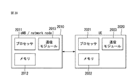
また、本発明の別の実施例に係る無線通信システムにおける反映型(reflective)QoS(Quality of Service)を実行するUE(User Equipment)において、信号を送受信するための通信モジュール(communication module)及び前記通信モジュールを制御するプロセッサを含み、前記プロセッサは、ネットワークからダウンリンクパケットを受信し、前記ダウンリンクパケットは、前記reflective QoSの適用が指示されたパケットである、前記ダウンリンクパケットに基づいてQoS規則を導出し、前記QoS規則を用いて、アップリンクパケットに前記ダウンリンクパケットのQoSのマーキングを適用して前記ネットワークへ送信し、前記QoS規則と連携したタイマーの満了前に前記ダウンリンクパケットを受信した場合、前記タイマーを再開始し得る。 In addition, a communication module for transmitting and receiving signals in a UE (User Packet) that executes reflected QoS (Quality of Service) in a wireless communication system according to another embodiment of the present invention, and the above. Includes a processor that controls a communication module, the processor receives a downlink packet from a network, and the downlink packet is a packet instructed to apply the reflective QoS, a QoS rule based on the downlink packet. Is derived, using the QoS rule, the QoS marking of the downlink packet is applied to the uplink packet and transmitted to the network, and the downlink packet is received before the expiration of the timer linked with the QoS rule. If so, the timer may be restarted.
また、前記プロセッサは、前記タイマーが満了となった場合、前記QoS規則を削除し得る。 Also, the processor may delete the QoS rule when the timer expires.
また、前記QoS規則は、前記ダウンリンクパケットから導出されたパケットフィルタ、前記ダウンリンクパケットのQoSのマーキング及び前記アップリンクパケットの評価(evaluate)順序を決定するために用いられる優先順位値を含み得る。 In addition, the QoS rule may include a packet filter derived from the downlink packet, a QoS marking of the downlink packet, and a priority value used to determine the evaluation order of the uplink packet. ..
本発明の実施例に係ると、reflective QoSを適用することによって、QoSのマーキングのためのシグナリングのオーバーヘッドが減らし、QoS手続が単純になるという効果が発生する。 According to the embodiment of the present invention, the application of reflective QoS has the effect of reducing the signaling overhead for marking QoS and simplifying the QoS procedure.
また、本発明の実施例に係ると、reflective QoSのタイマーを適用し、タイマーが満了となったreflective QoSをUEがリアルタイムで削除するようにすることで、不要なQoS規則を持続的に管理/格納することによって発生し得るUEの負担を大きく軽減するという効果が発生する。 Further, according to the embodiment of the present invention, an unnecessary QoS rule is continuously managed by applying a reflective QoS timer so that the UE deletes the reflective QoS that has expired in real time. The effect of greatly reducing the load on the UE that may occur by storing it occurs.
また、本発明の実施例に係ると、別にタイマーを開始/再開始するための指示子をシグナリングする必要がないので、シグナリングのオーバーヘッドが減少し、タイマー動作手続が簡便になるという効果がある。 Further, according to the embodiment of the present invention, since it is not necessary to separately signal the indicator for starting / restarting the timer, there is an effect that the overhead of signaling is reduced and the timer operation procedure is simplified.
本発明で得ることができる効果は、以上で言及した効果に制限されるものではなく、言及していないまた別の効果は、以下の記載から本発明が属する技術分野で通常の知識を有する者にとって明確に理解されるべきである。 The effects that can be obtained in the present invention are not limited to the effects mentioned above, and other effects that are not mentioned are those who have ordinary knowledge in the technical field to which the present invention belongs from the following description. Should be clearly understood.
本発明に関する理解を助けるために詳細な説明の一部として含まれる添付図面は、本発明に対する実施例を提供し、詳細な説明と共に本発明の技術的特徴を説明する。 The accompanying drawings included as part of a detailed description to aid an understanding of the invention provide examples of the invention and illustrate the technical features of the invention with detailed description.
以下、本発明にかかる好ましい実施形態を添付された図面を参照して詳細に説明する。添付された図面と共に以下に開示する詳細な説明は、本発明の例示的な実施形態を説明するためのものであり、本発明が実施され得る唯一の実施形態を示すためのものではない。以下の詳細な説明は、本発明の完全な理解を提供するために具体的な細部事項を含む。しかしながら、当業者は、本発明がこのような具体的な細部事項がなくても実施できることを理解すべきである。 Hereinafter, preferred embodiments of the present invention will be described in detail with reference to the accompanying drawings. The detailed description disclosed below, along with the accompanying drawings, is intended to illustrate exemplary embodiments of the invention and is not intended to indicate the only embodiment in which the invention can be practiced. The following detailed description includes specific details to provide a complete understanding of the present invention. However, those skilled in the art should understand that the present invention can be practiced without such specific details.
いくつかの場合、本発明の概念が曖昧になることを避けるために、公知の構造及び装置は省略されるか、または各構造及び装置の核心機能を重心にしたブロック図形式で示されることができる。 In some cases, known structures and devices may be omitted or shown in block diagram format with the core function of each structure and device as the center of gravity to avoid obscuring the concepts of the present invention. it can.
本明細書において、基地局は、端末と直接的に通信を行うネットワークの終端ノード(terminal node)としての意味を有する。本文書において基地局により行われると説明された特定動作は、場合によっては、基地局の上位ノード(upper node)により行われてもよい。すなわち、基地局を含む複数のネットワークノード(network nodes)からなるネットワークにおいて端末との通信のために行われる多様な動作は、基地局または基地局以外の他のネットワークノードにより行われうることは明らかである。「基地局(BS:Base Station)」は、固定局(fixed station)、NodeB、eNB(evolved−NodeB)、BTS(base transceiver system)、アクセスポイント(AP:Access Point)などの用語により代替され得る。また、「端末(Terminal)」は、固定されるか、または移動性を有し得、UE(User Equipment)、MS(Mobile Station)、UT(user terminal)、MSS(Mobile Subscriber Station)、SS(Subscriber Station)、AMS(Advanced Mobile Station)、WT(Wireless terminal)、MTC(Machine−Type Communication)装置、M2M(Machine−to−Machine)装置、D2D(Device−to−Device)装置などの用語に代替され得る。 In the present specification, the base station has a meaning as a terminal node of a network that directly communicates with a terminal. In some cases, the specific operation described as being performed by the base station in this document may be performed by an upper node of the base station. That is, it is clear that various operations performed for communication with a terminal in a network consisting of a plurality of network nodes (newwork nodes) including a base station can be performed by the base station or a network node other than the base station. Is. "Base station (BS)" can be replaced by terms such as fixed station (fixed station), NodeB, eNB (evolved-NodeB), BTS (base transceiver system), and access point (AP: Access Point). .. In addition, the "terminal" may be fixed or mobile, and may be UE (User Equipment), MS (Mobile Station), UT (user tertiary), MSS (Mobile Subscriber Station), SS ( Subscriber Station), AMS (Advanced Mobile Station), WT (Wireless terminal), MTC (Machine-Type Communication) device, M2M (Machine-to-Machine) device, M2M (Machine-to-Machine) device, D2D Can be done.
以下、ダウンリンク(DL:downlink)は、基地局から端末への通信を意味し、アップリンク(UL:uplink)は、端末から基地局への通信を意味する。ダウンリンクにおける送信機は、基地局の一部で、受信機は、端末の一部であり得る。アップリンクにおける送信機は、端末の一部で、受信機は、基地局の一部であり得る。 Hereinafter, downlink (DL: download) means communication from a base station to a terminal, and uplink (UL: uplink) means communication from a terminal to a base station. The transmitter in the downlink can be part of a base station and the receiver can be part of a terminal. The transmitter in the uplink can be part of the terminal and the receiver can be part of the base station.
以下の説明において使用される特定用語は、本発明の理解に役立つために提供されたものであり、このような特定用語の使用は、本発明の技術的思想から外れない範囲で他の形態に変更され得る。 The specific terms used in the following description are provided to aid in the understanding of the present invention, and the use of such specific terms may be in other forms without departing from the technical ideas of the present invention. Can be changed.
以下の技術は、CDMA(code division multiple access)、FDMA(frequency division multiple access)、TDMA(time division multiple access)、OFDMA(orthogonal frequency division multiple access)、SC−FDMA(single carrier frequency division multiple access)、NOMA(non−orthogonal multiple access)などのような多様な無線接続システムに利用され得る。CDMAは、UTRA(universal terrestrial radio access)またはCDMA2000のような無線技術(radio technology)により具現できる。TDMAは、GSM(global system for mobile communications)/GPRS(general packet radio service)/EDGE(enhanced data rates for GSM evolution)のような無線技術により具現できる。OFDMAは、IEEE 802.11(Wi−Fi)、IEEE 802.16(WiMAX)、IEEE 802−20、E−UTRA(evolved UTRA)などのような無線技術により具現できる。UTRAは、UMTS(universal mobile telecommunications system)の一部である。3GPP(3rd generation partnership project)LTE(long term evolution)は、E−UTRAを使用するE−UMTS(evolved UMTS)の一部であって、ダウンリンクにおいてOFDMAを採用し、アップリンクにおいてSC−FDMAを採用する。LTE−A(advanced)は、3GPP LTEの進化である。 The following technologies, CDMA (code division multiple access), FDMA (frequency division multiple access), TDMA (time division multiple access), OFDMA (orthogonal frequency division multiple access), SC-FDMA (single carrier frequency division multiple access), It can be used in various wireless connection systems such as NOMA (non-orthogonal multiple access). CDMA can be embodied by radio technology (radio technology) such as UTRA (universal terrestrial radio access) or CDMA2000. TDMA is embodied by wireless technology such as GSM (global system for mobile communications) / GPRS (general packet radio service) / EDGE (enhanced data rates for GSM evolution). OFDMA can be embodied by wireless technologies such as IEEE 802.11 (Wi-Fi), IEEE 802.16 (WiMAX), IEEE 802-20, and E-UTRA (evolved UTRA). UTRA is part of UMTS (universal mobile telecommunications system). 3GPP (3rd generation partnership project) LTE (long term evolution) is a part of E-UMTS (evolved UMTS) that uses E-UTRA, adopts OFDMA in the downlink, and SC-FDMA in the uplink. adopt. LTE-A (advanced) is an evolution of 3GPP LTE.
本発明の実施例は、無線接続システムであるIEEE 802、3GPP、及び3GPP2のうち少なくとも一つに開示された標準文書によって裏付けられることができる。すなわち、本発明の実施例のうち、本発明の技術的思想を明確に示すために説明していない段階または部分は、前記文書によって裏付けられることができる。また、本文書で開示している全ての用語は、前記標準文書によって説明されることができる。 The embodiments of the present invention can be supported by standard documents disclosed in at least one of the wireless connectivity systems IEEE 802, 3GPP, and 3GPP2. That is, any step or portion of an embodiment of the invention that has not been described to articulate the technical ideas of the invention can be supported by the document. In addition, all terms disclosed in this document can be explained by the standard document.
説明を明確にするために、3GPP LTE/LTE−Aを中心に記述するが、本発明の技術的特徴がこれに制限されるわけではない。 For the sake of clarity, 3GPP LTE / LTE-A will be mainly described, but the technical features of the present invention are not limited thereto.
本文書で使用されることができる用語は次のように定義される。 The terms that can be used in this document are defined as follows:
− UMTS(Universal Mobile Telecommunications System): 3GPPによって開発された、GSM(Global System for Mobile Communication) ベースの3世代(Generation)移動通信技術 -UMTS (Universal Mobile Telecommunications System): GSM (Global System for Mobile Communication) -based 3rd generation (Generation) mobile communication technology developed by 3GPP.
− EPS(Evolved Packet System):IP(Internet protocol) ベースのパケット交換(packet switched)のコアネットワークであるEPC(Evolved Packet Core)やLTE、UTRAN等のアクセスネットワークで構成されたネットワークシステム。UMTSが進化した形態のネットワークである。 -EPS (Evolved Packet System): A network system composed of access networks such as EPC (Evolved Packet Core), which is a core network of IP (Internet Protocol) -based packet switching, and LTE and UTRAN. UMTS is an evolved form of network.
− NodeB:UMTSネットワークの基地局。屋外に設置し、カバレッジはマクロセル(macro cell)規模である。 − NodeB: UMTS network base station. Installed outdoors, coverage is macro cell scale.
− eNodeB:EPSネットワークの基地局。屋外に設置し、カバレッジはマクロセル(macro cell)規模である。 -ENodeB: Base station of EPS network. Installed outdoors, coverage is macro cell scale.
− 端末(User Equipment):ユーザー機器。端末は、端末(terminal)、ME(Mobile Equipment)、MS(Mobile Station)等の用語として言及され得る。また、端末は、ラップタップ、携帯電話、PDA(Personal Digital Assistant)、スマートフォン、マルチメディア機器等のように携帯可能な機器であってもよく、またはPC(Personal Computer)、車両搭載装置のように携帯できない機器であってもよい。MTCに関する内容で、端末または端末という用語は、MTC端末を指称し得る。 -Terminal (User Equipment): User device. The terminal may be referred to as a term such as terminal, ME (Mobile Appliance), MS (Mobile Station), and the like. Further, the terminal may be a portable device such as a lap tap, a mobile phone, a PDA (Personal Digital Assistant), a smartphone, a multimedia device, or a PC (Personal Computer), a vehicle-mounted device, or the like. It may be a device that cannot be carried. In the content relating to MTC, the term terminal or terminal may refer to an MTC terminal.
− IMS(Ip Multimedia Subsystem):マルチメディアサービスをIPベースに提供するサブシステム。 -IMS (Ip Multimedia Subsystem): A subsystem that provides multimedia services based on IP.
− IMSI(International Mobile Subscriber Identity):移動通信ネットワークで国際的に固有に割り当てられるユーザー識別子。 -IMSI (International Mobile Subscriber Identity): A user identifier that is uniquely assigned internationally in a mobile communication network.
− MTC(Machine Type Communication):人間の介入なくともマシンにより行われる通信。M2M(Machine to Machine)通信とも指称し得る。 -MTC (Machine Type Communication): Communication performed by a machine without human intervention. It can also be referred to as M2M (Machine to Machine) communication.
− MTC端末(MTC UEまたはMTC deviceまたはMTC装置):移動通信ネットワークを介した通信(例えば、PLMNを介してMTCサーバーと通信)機能を有し、MTC機能を行う端末(例えば、自販機、検針器等)。 -MTC terminal (MTC UE or MTC device or MTC device): A terminal having a communication function via a mobile communication network (for example, communicating with an MTC server via PLMN) and performing an MTC function (for example, a vending machine or a meter reader). etc).
− MTCサーバー(MTC server):MTC端末を管理するネットワーク上のサーバー。移動通信ネットワークの内部または外部に存在し得る。MTCユーザーがアクセス(access)することができるインターフェースを有し得る。また、MTCサーバーは、他のサーバーにMTC関連のサービスを提供してもよく(SCS(Services Capability Server)形態)、自身がMTCアプリケーションサーバーであってもよい。 -MTC server (MTC server): A server on the network that manages MTC terminals. It can be inside or outside the mobile communication network. It may have an interface that MTC users can access. Further, the MTC server may provide MTC-related services to other servers (SCS (Services Capacity Server) form), or may itself be an MTC application server.
− (MTC)アプリケーション(application):(MTCが適用される)サービス(例えば、遠隔検針、物量移動追跡、気象観測センサ等) -(MTC) application: Services (where MTC applies) (eg, remote meter reading, volume movement tracking, meteorological observation sensors, etc.)
− (MTC)アプリケーションサーバー:(MTC)アプリケーションが実行されるネットワーク上のサーバー -(MTC) Application Server: A server on the network where the (MTC) application runs
− MTC特徴(MTC feature):MTCアプリケーションを支援するためのネットワークの機能。例えば、MTCモニタリング(monitoring)は、遠隔検針等のMTCアプリケーションで装備紛失等に備えるための特徴であり、低い移動性(low mobility)は、自販機のようなMTC端末に対するMTCアプリケーションのための特徴である。 -MTC features: The ability of the network to support MTC applications. For example, MTC monitoring is a feature for MTC applications such as remote meter reading to prepare for equipment loss, and low mobility is a feature for MTC applications for MTC terminals such as vending machines. is there.
− MTCユーザー(MTC User):MTCユーザーはMTCサーバーにより提供されるサービスを使用する。 -MTC User (MTC User): The MTC user uses the services provided by the MTC server.
− MTC加入者(MTC subscriber):ネットワークオペレーターと接続関係を有しており、一つ以上のMTC端末にサービスを提供するエンティティ(entity)である。 -MTC subscriber (MTC subscriber): An entity that has a connection relationship with a network operator and provides services to one or more MTC terminals.
− MTCグループ(MTC group):少なくとも一つ以上のMTC特徴を共有し、MTC加入者に属したMTC端末のグループを意味する。 -MTC group: means a group of MTC terminals that share at least one or more MTC features and belong to an MTC subscriber.
− サービス機能サーバー(SCS:Services Capability Server):HPLMN(Home PLMN)上のMTC−IWF(MTC InterWorking Function)及びMTC端末と通信するためのエンティティであって、3GPPネットワークと接続されている。SCSは、一つ以上のMTCアプリケーションによる使用のための能力(capability)を提供する。 -Service Function Server (SCS): An entity for communicating with the MTC-IWF (MTC InterWorking Function) and MTC terminal on the HPLMN (Home PLMN), which is connected to the 3GPP network. The SCS provides capacity for use by one or more MTC applications.
− 外部識別子(External Identifier):3GPPネットワークの外部エンティティ(例えば、SCSまたはアプリケーションサーバー)がMTC端末(またはMTC端末が属した加入者)を指す(または識別する)ために使用する識別子(identifier)であって、全世界的に固有(globally unique)である。外部識別子は、次のようにドメイン識別子(Domain Identifier)とローカル識別子(Local Identifier)とで構成される。 -External Identifier: An identifier used by an external entity (eg, SCS or application server) in a 3GPP network to point to (or identify) an MTC terminal (or the subscriber to which the MTC terminal belongs). It is globally unique. The external identifier is composed of a domain identifier (Domain Identifier) and a local identifier (Local Identifier) as follows.
− ドメイン識別子(Domain Identifier):移動通信ネットワーク事業者の制御下にあるドメインを識別するための識別子。一つの事業者は、互いに異なるサービスへの接続を提供するためにサービス別にドメイン識別子を使用することができる。 -Domain Identifier: An identifier for identifying a domain under the control of a mobile communication network operator. One operator can use domain identifiers by service to provide connections to different services.
− ローカル識別子(Local Identifier):IMSI(International Mobile Subscriber Identity)を類推または獲得するのに使用される識別子。ローカル識別子は、アプリケーションドメイン内では固有(unique)でなければならず、移動通信ネットワーク事業者によって管理される。 -Local Identifier (Local Identifier): An identifier used to infer or acquire the IMSI (International Mobile Subscriber Identity). The local identifier must be unique within the application domain and is managed by the mobile network operator.
− RAN(Radio Access Network):3GPPネットワークでNode B及びこれを制御するRNC(Radio Network Controller)、eNodeBを含む単位。端末の端に存在し、コアネットワークへの連結を提供する。 -RAN (Radio Access Network): A unit including Node B and RNC (Radio Network Controller) and eNodeB that control it in a 3GPP network. It exists at the edge of the terminal and provides connectivity to the core network.
− HLR(Home Location Register)/HSS(Home Subscriber Server):3GPPネットワーク内の加入者情報を有しているデータベース。HSSは設定格納(configuration storage)、識別子管理(identity management)、ユーザー状態格納等の機能を行うことができる。 -HLR (Home Location Register) / HSS (Home Subscriber Server): A database that holds subscriber information within a 3GPP network. The HSS can perform functions such as configuration storage, identity management, and user status storage.
− RANAP(RAN Application Part):RANとコアネットワークの制御を担当するノード(即ち、MME(Mobility Management Entity)/SGSN(Serving GPRS(General Packet Radio Service)Supporting Node)/MSC(Mobile Switching Center))間のインターフェース。 -RANAP (RAN Application Part): A node in charge of controlling the RAN and the core network (that is, MME (Mobile Management Interface) / SGSN (Serving GPRS (General Packet Radio Service) Support Interface) Interface.
− PLMN(Public Land Mobile Network):個人に移動通信サービスを提供する目的で構成されたネットワーク。オペレーター別に区分されて構成されることができる。 -PLMN (Public Land Mobile Network): A network configured for the purpose of providing mobile communication services to individuals. It can be configured by being divided by operator.
− NAS(Non−Access Stratum):UMTS、EPSプロトコルスタックで端末とコアネットワーク間のシグナリング、トラフィックメッセージをやり取りするための機能的な層。端末の移動性を支援し、端末とPDN GW間のIP連結を確立及び維持するセッション管理手続を支援することを主な機能とする。 -NAS (Non-Access Stratum): A functional layer for exchanging signaling and traffic messages between terminals and core networks in the UMTS and EPS protocol stacks. Its main function is to support the mobility of the terminal and to support the session management procedure to establish and maintain the IP connection between the terminal and the PDN GW.
− SCEF(Service Capability Exposure Function):3GPPネットワークインタフェースにより提供されるサービス及び能力(capability)を安全に露出するための手段を提供するサービス能力露出(Service capability exposure)のための3GPPアーキテクチャー内のエンティティ。 -SCEF (Service Capacity Exposure Function): An entity for a service capability exposure (Service Capability Exposure) that provides a means for safely exposing the services and capabilities provided by the 3GPP network interface. ..
以下、上記のように定義された用語に基づいて、本発明について記述する。 Hereinafter, the present invention will be described based on the terms defined as described above.
本発明が適用され得るシステム一般General system to which the present invention can be applied
図1は、本発明が適用され得るEPS(Evolved Packet System)を簡略に例示する図である。 FIG. 1 is a diagram simply illustrating EPS (Evolved Package System) to which the present invention can be applied.
図1のネットワークの構造図は、EPC(Evolved Packet Core)を含むEPS(Evolved Packet System)の構造を、これを簡略に再構成したものである。 The network structure diagram of FIG. 1 is a simplified reconstruction of the structure of an EPS (Evolved Package System) including an EPC (Evolved Package Core).
EPC(Evolved Packet Core)は、3GPP技術の性能を向上するためのSAE(System Architecture Evolution)の中核的な要素である。SAEは、様々な種類のネットワーク間の移動性を支援するネットワークの構造を決定する研究課題に該当する。SAEは、例えば、IPベースに多様な無線接続技術を支援し、より向上したデータ送信能力を提供する等の最適化されたパケット−ベースのシステムを提供することを目標とする。 EPC (Evolved Package Core) is a core element of SAE (System Archive Evolution) for improving the performance of 3GPP technology. SAE is a research subject that determines the structure of networks that support mobility between various types of networks. The SAE aims to provide optimized packet-based systems, such as supporting a variety of wireless connectivity technologies based on IP and providing improved data transmission capabilities.
具体的に、EPCは3GPP LTEシステムのためのIP移動通信システムのコアネットワーク(Core Network)であり、パケット−ベースのリアルタイム及び非リアルタイムのサービスを支援することができる。既存の移動通信システム(即ち、2世代または3世代移動通信システム)では、音声のためのCS(Circuit−Switched)及びデータのためのPS(Packet−Switched)の二つの区別されるサブ−ドメインを介してコアネットワークの機能が具現された。しかし、3世代移動通信システムの進化である3GPP LTEシステムでは、CS及びPSのサブ−ドメインが一つのIPドメインとして単一化した。即ち、3GPP LTEシステムでは、IP能力(capability)を有する端末と端末間の連結が、IPベースの基地局(例えば、eNodeB(evolved Node B))、EPC、アプリケーションドメイン(例えば、IMS)を介して構成されることができる。即ち、EPCは、端対端(end−to−end)のIPサービスの具現に必須的な構造である。 Specifically, EPC is the core network of IP mobile communication systems for 3GPP LTE systems and can support packet-based real-time and non-real-time services. Existing mobile communication systems (ie, 2nd or 3rd generation mobile communication systems) have two distinct subdomains: CS (Circuit-Switched) for voice and PS (Packet-Switched) for data. Through this, the functions of the core network were realized. However, in the 3GPP LTE system, which is an evolution of the 3G mobile communication system, the CS and PS subdomains are unified as one IP domain. That is, in the 3GPP LTE system, the connection between terminals having IP capability (capability) is performed via an IP-based base station (for example, eNodeB (evolved Node B)), EPC, and an application domain (for example, IMS). Can be configured. That is, the EPC is an indispensable structure for realizing an end-to-end IP service.
EPCは多様な構成要素を含み得、図1では、そのうち一部に該当する、SGW(Serving Gateway)(又はS−GW)、PDN GW(Packet Data Network Gateway)(若しくはPGW又はP−GW)、MME(Mobility Management Entity)、SGSN(Serving GPRS(General Packet Radio Service)Supporting Node)、ePDG(enhanced Packet Data Gateway)を示す。 The EPC may include various components, and in FIG. 1, SGW (Serving Gateway) (or S-GW), PDN GW (Packet Data Network Gateway) (or PGW or P-GW), which correspond to some of them, MME (mobility management entry), SGSN (Serving GPRS (General Packet Radio Service) Supporting Node), ePDG (enhanced Packet Data Gateway) are shown.
SGWは、無線接続ネットワーク(RAN)とコアネットワーク間の境界点として動作し、eNodeBとPDN GW間のデータ経路を維持する機能をする要素である。また、端末がeNodeBによってサービング(serving)される領域にかけて移動する場合、SGWはローカル移動性アンカーポイント(anchor point)の役割を果たす。即ち、E−UTRAN(3GPPリリース8の以降から定義されるEvolved−UMTS(Universal Mobile Telecommunications System)Terrestrial Radio Access Network)内での移動性のためにSGWを介してパケットがルーティングされることができる。さらに、SGWは他の3GPPネットワーク(3GPPリリース8の以前に定義されるRAN、例えば、UTRANまたはGERAN(GSM(Global System for Mobile Communication)/EDGE(Enhanced Data rates for Global Evolution)Radio Access Network)との移動性のためのアンカーポイントとして機能することもできる。 The SGW is an element that operates as a boundary point between the radio connection network (RAN) and the core network and functions to maintain a data path between the eNodeB and the PDN GW. Also, when the terminal moves over an area served by the eNodeB, the SGW acts as a local anchor point. That is, packets can be routed via the SGW for mobility within E-UTRAN (Evolved-UMTS (Universal Mobile Telecommunications System) Terrestrial Radio Access Network, which has been defined since 3GPP Release 8). In addition, SGWs include other 3GPP networks (RANs previously defined in 3GPP Release 8, such as UTRAN or GERAN (GSM (Global System for Mobile Communication) / EDGE (Enhanced Data rates for Radio) Radio) and Radio Access). It can also serve as an anchor point for mobility.
PDN GWは、パケットデータネットワークに向かったデータインターフェースの終端点(termination point)に該当する。PDN GWは、ポリシー執行特徴(Policy enforcement features)、パケットフィルタリング(packet filtering)、課金支援(charging support)等をサポートすることができる。また、3GPPネットワークと非−3GPP(non−3GPP)ネットワーク(例えば、I−WLAN(Interworking Wireless Local Area Network)のような信頼できないネットワーク、CDMA(Code Division Multiple Access)ネットワークや、Wimaxのような信頼できるネットワーク)との移動性管理のためのアンカーポイントの役割を果たすことができる。 The PDN GW corresponds to the termination point of the data interface toward the packet data network. The PDN GW can support policy enforcement features, packet filtering, charging support, and the like. Also, 3GPP networks and non-3GPP (non-3GPP) networks (eg, unreliable networks such as I-WLAN (Interworking Wireless Local Area Network), reliable networks such as CDMA (Code Division Multi-Access) networks, and Wimax. It can act as an anchor point for mobility management with (network).
図1のネットワーク構造の例示では、SGWとPDN GWが別のゲートウェイで構成されることを示すが、二つのゲートウェイが単一のゲートウェイ構成のオプション(Single Gateway Configuration Option)によって具現されることもできる。 Although the example of the network structure in FIG. 1 shows that the SGW and the PDN GW are configured by different gateways, the two gateways can also be embodied by a single gateway configuration option (Single Gateway Configuration Option). ..
MMEは、端末のネットワーク連結に対するアクセス、ネットワークリソースの割り当て、トラッキング(tracking)、ページング(paging)、ローミング(roaming)、及びハンドオーバー等を支援するためのシグナリング及び制御機能を行う要素である。MMEは、加入者及びセッション管理に関するコントロールプレーン機能を制御する。MMEは、数多くのeNodeBを管理し、他の2G/3Gネットワークに対するハンドオーバーのための従来のゲートウェイの選択のためのシグナリングを行う。また、MMEは、保安過程(Security Procedures)、端末対ネットワークセッションハンドリング(Termianl−to−network Session Handling)、遊休端末位置決定管理(Idle Terminal Location Management)等の機能を行う。 The MME is an element that performs signaling and control functions for supporting access to a terminal's network connection, allocation of network resources, tracking, paging, roaming, handover, and the like. The MME controls control plane functions for subscriber and session management. The MME manages a number of eNodeBs and provides signaling for the selection of traditional gateways for handovers to other 2G / 3G networks. In addition, the MME performs functions such as security processes, terminal-to-network session handling (Terminal-to-network Session Handling), and idle terminal positioning management (Idle Thermal Location Management).
SGSNは、他の3GPPネットワーク(例えば、GPRSネットワーク)に対するユーザーの移動性管理及び認証(authentication)のような全てのパケットデータをハンドリングする。 The SGSN handles all packet data such as user mobility management and authentication for other 3GPP networks (eg GPRS networks).
ePDGは、信頼できない非−3GPPネットワーク(例えば、I−WLAN、WiFiホットスポット(hotspot)等)に対する保安ノードとしての役割を果たす。 The ePDG serves as a security node for unreliable non-3GPP networks (eg, I-WLAN, WiFi hotspots, etc.).
図1を参照として説明したように、IP能力を有する端末は、3GPPアクセスはもちろん、非−3GPPアクセスベースでもEPC内の多様な要素を経由して、事業者(即ち、オペレーター(operator))が提供するIPサービスネットワーク(例えば、IMS)にアクセスすることができる。 As explained with reference to FIG. 1, a terminal having IP capability can be operated by an operator (that is, an operator) via various elements in the EPC not only for 3GPP access but also for non-3GPP access base. You can access the provided IP service network (eg, IMS).
また、図1では、多様なリファレンスポイント(例えば、S1−U、S1−MME等)を示す。3GPPシステムでは、E−UTRAN及びEPCの異なる機能個体(functional entity)に存在する2つの機能を連結する概念的なリンクをリファレンスポイント(reference point)と定義する。次の表1は、図1に示すリファレンスポイントを整理したものである。表1の例示以外にもネットワーク構造によって様々なリファレンスポイント(reference point)が存在し得る。 Further, FIG. 1 shows various reference points (for example, S1-U, S1-MME, etc.). In the 3GPP system, a conceptual link connecting two functions existing in different functional entities of E-UTRAN and EPC is defined as a reference point. Table 1 below summarizes the reference points shown in FIG. In addition to the examples in Table 1, various reference points may exist depending on the network structure.

図1に示すリファレンスポイントのうちS2a及びS2bは、非−3GPPインターフェースに該当する。S2aは信頼できる非−3GPPアクセス及びPDN GW間の関連制御及び移動性リソースをユーザープレーンに提供するリファレンスポイントである。S2bは、ePDG及びPDN GW間の関連制御及び移動性支援をユーザープレーンに提供するリファレンスポイントである。 Of the reference points shown in FIG. 1, S2a and S2b correspond to non-3GPP interfaces. S2a is a reference point that provides the user plane with reliable non-3GPP access and association control and mobility resources between PDN GWs. S2b is a reference point that provides the user plane with related control and mobility support between the ePDG and PDN GW.
図2は、本発明が適用され得るE−UTRAN(evolved universal terrestrial radio access network)のネットワーク構造の一例を示す。 FIG. 2 shows an example of a network structure of E-UTRAN (evolved universal radio access network) to which the present invention can be applied.
E−UTRANシステムは、既存のUTRANシステムで進化したシステムであって、例えば、3GPP LTE/LTE−Aシステムであり得る。通信ネットワークは、IMS及びパケットデータを介して音声(voice)(例えば、VoIP(Voice over Internet Protocol))のような多様な通信サービスを提供するために広範囲に配置される。 The E-UTRAN system is an evolution of the existing UTRAN system and can be, for example, a 3GPP LTE / LTE-A system. Communication networks are extensively deployed to provide a variety of communication services such as voice (eg, Voice over Internet Protocol) via IMS and packet data.
図2を参照すると、E−UMTSネットワークは、E−UTRAN、EPC、及び一つ以上のUEを含む。E−UTRANは端末にコントロールプレーン(control plane)とユーザープレーン(user plane)のプロトコルを提供するeNBで構成され、eNBはX2のインターフェースを介して連結される。 Referring to FIG. 2, the E-UMTS network includes an E-UTRAN, an EPC, and one or more UEs. The E-UTRAN consists of an eNB that provides the terminal with a control plane and a user plane protocol, and the eNBs are connected via an X2 interface.
X2ユーザープレーンのインターフェース(X2−U)は、eNB間で定義される。X2−Uのインターフェースは、ユーザープレーンのPDU(protocol data unit)の保障されない伝達(non guaranteed delivery)を提供する。X2コントロールプレーンのインターフェース(X2−CP)は、二つの隣り合うeNB間で定義される。X2−CPは、eNB間のコンテキスト(context)伝達、ソースeNBとターゲットNB間のユーザープレーントンネルの制御、ハンドオーバー関連メッセージの伝達、アップリンク負荷管理等の機能を行う。 The X2 user plane interface (X2-U) is defined between eNBs. The X2-U interface provides non-guaranteed delivery of user plane PDUs (protocol data units). The interface (X2-CP) of the X2 control plane is defined between two adjacent eNBs. The X2-CP performs functions such as context transmission between eNBs, control of user plane tunnels between source eNBs and target NBs, transmission of handover-related messages, and uplink load management.
eNBは、無線インターフェースを介して端末と連結され、S1のインターフェースを介してEPC(evolved packet core)に連結される。 The eNB is connected to the terminal via the wireless interface and is connected to the EPC (evolved packet core) via the interface of S1.
S1ユーザープレーンのインターフェース(S1−U)は、eNBとサービングゲートウェイ(S−GW:serving gateway)間で定義される。S1コントロールプレーンのインターフェース(S1−MME)は、eNBと移動性管理個体(MME:mobility management entity)間で定義される。S1のインターフェースは、EPS(evolved packet system)ベアラーサービス管理機能、NAS(non−access stratum)シグナリングトランスポート機能、ネットワークシェアリング、MME負荷バランシング機能等を行う。S1のインターフェースはeNBとMME/S−GW間に多対多の関係(many−to−many−relation)を支援する。 The interface (S1-U) of the S1 user plane is defined between the eNB and the serving gateway (S-GW). The interface (S1-MME) of the S1 control plane is defined between the eNB and the mobility management entity (MME). The interface of S1 performs an EPS (evolved packet system) bearer service management function, a NAS (non-access system) signaling transport function, network sharing, an MME load balancing function, and the like. The S1 interface supports a many-to-many-relation between the eNB and the MME / S-GW.
MMEは、NASシグナリング保安(security)、AS(Access Stratum)保安(security)制御、3GPPアクセスネットワーク間の移動性を支援するためのCN(Core Network)ノード間(Inter−CN)シグナリング、(ページング再送信の実行及び制御を含んで)アイドル(IDLE)モードUE接近性(reachability)、(アイドル及びアクティブモード端末のための)トラッキング領域識別子(TAI:Tracking Area Identity)管理、PDN GW及びSGW選択、MMEが変更されるハンドオーバーのためのMME選択、2Gまたは3G 3GPPアクセスネットワークへのハンドオーバーのためのSGSN選択、ローミング(roaming)、認証(authentication)、専用ベアラーの確立(dedicated bearer establishment)を含むベアラー管理機能、公共警報システム(PWS:Public Warning System)(地震及びツナミ警報システム(ETWS:Earthquake and Tsunami Warning System)、及び商用モバイル警報システム(CMAS:Commercial Mobile Alert System)を含む)メッセージ送信の支援等様々な機能を行い得る。 MME is a NAS signaling security (security), AS (Access Stratum) security (security) control, CN (Core Network) inter-node (Inter-CN) signaling to support mobility between 3GPP access networks, (page re-paged). Idle (IDLE) mode UE accessibility (reachability), tracking area identifier (TAI: Tracking Area Identity) management (for idle and active mode terminals), PDN GW and SGW selection, MME, including transmission execution and control. Bearer including MME selection for handover to be modified, SGSN selection for handover to a 2G or 3G 3GPP access network, roaming, authentication, and dedicated bearer restoration. Management function, public warning system (PWS: Public Warning System) (Earthquake and Tsunami warning system (ETWS: Earthquake and Tsunami Warning System), and commercial mobile warning system (CMAS: Commercial System) Message transmission system, etc. It can perform various functions.
図3は、本発明が適用され得る無線通信システムにおけるE−UTRAN及びEPCの構造を例示する。 FIG. 3 illustrates the structure of E-UTRAN and EPC in a wireless communication system to which the present invention can be applied.
図3を参照すると、eNBはゲートウェイ(例えば、MME)の選択、無線リソース制御(RRC:radio resource control)の活性(activation)の間にゲートウェイへのルーティング、放送チャンネル(BCH:broadcast channel)のスケジューリング及び送信、アップリンク及びダウンリンクからUEへ動的リソースの割り当て、かつLTE−ACTIVE状態で移動性制御連結の機能を行い得る。前述したように、EPC内におけるゲートウェイは、ページングの開始(orgination)、LTE_IDLE状態の管理、ユーザープレーン(user plane)の暗号化(ciphering)、システム構造の進化(SAE:System Architecture Evolution)ベアラー制御、かつNASシグナリングの暗号化(ciphering)及び完全性(intergrity)保護の機能を行い得る。 Referring to FIG. 3, the eNB selects a gateway (for example, MME), routes to the gateway during activation of radio resource control (RRC), and schedules a broadcast channel (BCH). And can perform the function of dynamic resource allocation from transmit, uplink and downlink to UE, and mobility control concatenation in LTE-ACTIVE state. As mentioned above, the gateway in the EPC is the initiation of paging, the management of the LTE_IDLE state, the encryption of the user plane (user plane), the evolution of the system structure (SAE: System Archive Evolution) bearer control, And it can perform the functions of encryption and integrity protection of NAS signaling.
図4は、本発明が適用され得る無線通信システムにおける端末とE−UTRAN間の無線インターフェースプロトコル(radio interface protocol)の構造を示す。 FIG. 4 shows the structure of a radio interface protocol between a terminal and an E-UTRAN in a wireless communication system to which the present invention can be applied.
図4(a)は、コントロールプレーン(control plane)に対する無線プロトコルの構造を示し、図4(b)は、ユーザープレーン(user plane)に対する無線プロトコルの構造を示す。 FIG. 4A shows the structure of the radio protocol for the control plane, and FIG. 4B shows the structure of the radio protocol for the user plane.
図4を参照すると、端末とE−UTRAN間の無線インターフェースプロトコルの層は、通信システムの技術分野に公知となった広く知られている開放型システム間の相互接続(OSI:open system interconnection)の標準モデルの下位3層に基づき、第1層L1、第2層L2、及び第3層L3に分割できる。端末とE−UTRAN間の無線インターフェースプロトコルは、水平的に物理層(physical layer)、データリンク層(data link layer)、及びネットワーク層(network layer)からなり、垂直的にはデータ情報の送信のためのプロトコルスタック(protocol stack)のユーザープレーン(user plane)と、制御信号(signaling)の伝達のためのプロトコルスタックであるコントロールプレーン(control plane)とに区分される。 Referring to FIG. 4, the layer of wireless interface protocol between the terminal and E-UTRAN is an interconnection (OSI: open system interconnection) between widely known open systems known in the technical field of communication systems. Based on the lower three layers of the standard model, it can be divided into a first layer L1, a second layer L2, and a third layer L3. The wireless interface protocol between the terminal and E-UTRAN consists of a physical layer, a data link layer, and a network layer horizontally, and vertically transmits data information. It is divided into a user plane, which is a protocol stack for data, and a control plane, which is a protocol stack for transmitting control signals (signaling).
コントロールプレーンは、端末とネットワークが呼を管理するために利用する制御メッセージが送信される通路を意味する。ユーザープレーンは、アプリケーション層で生成されたデータ、例えば、音声データ又はインターネットパケットデータ等が送信される通路を意味する。以下、無線プロトコルのコントロールプレーンとユーザープレーンの各層を説明する。 The control plane means the passage through which control messages used by terminals and networks to manage calls are transmitted. The user plane means a passage through which data generated in the application layer, such as voice data or Internet packet data, is transmitted. Each layer of the control plane and the user plane of the wireless protocol will be described below.
第1層L1である物理層(PHY:physical layer)は、物理チャンネル(physical channel)を用いることによって、上位層への情報送信サービス(information transfer service)を提供する。物理層は、上位レベルに位置した媒体接続制御(MAC:medium access control)層に転送チャンネル(transport channel)を介して連結され、転送チャンネルを介してMAC層と物理層間でデータが送信される。転送チャンネルは、無線インターフェースを介してデータがどのように、どんな特徴で送信されるかによって分類される。また、互いに異なる物理層の間、送信端の物理層と受信端の物理層間には物理チャンネル(physical channel)を介してデータが送信される。物理層は、 OFDM(orthogonal frequency division multiplexing)方式で変調され、時間と周波数を無線資源として活用する。 The physical layer (PHY: physical layer), which is the first layer L1, provides an information transmission service (information transfer service) to an upper layer by using a physical channel. The physical layer is connected to a medium access control (MAC) layer located at a higher level via a transfer channel (transport channel), and data is transmitted between the MAC layer and the physical layer via the transfer channel. Transfer channels are categorized according to how and with what characteristics data is transmitted over the wireless interface. Further, between different physical layers, data is transmitted between the physical layer at the transmitting end and the physical layer at the receiving end via a physical channel. The physical layer is modulated by an OFDM (orthogonal frequency division multiplexing) method and utilizes time and frequency as radio resources.
物理層で用いられる幾つかの物理制御チャンネルがある。物理ダウンリンク制御チャンネル(PDCCH: physical downlink control channel)は、端末にページングチャンネル(PCH:paging channel)とダウンリンク共有チャンネル(DL−SCH: downlink shared channel)のリソース割当、及びアップリンク共有チャンネル(UL−SCH: uplink shared channel)と関連したHARQ(hybrid automatic repeat request)情報を知らせる。また、PDCCHは、端末にアップリング送信のリソース割当を知らせるアップリンクの承認(UL grant)を運ぶことができる。物理制御フォーマット指示子チャンネル(PDFICH:physical control format indicator channel)は、端末にPDCCHに用いられるOFDMシンボルの数を知らせ、毎サブフレーム毎に送信される。物理HARQ指示子チャンネル(PHICH:physical HARQ indicator channel)は、アップリンク送信の応答として、 HARQ ACK(acknowledge)/NACK(non−acknowledge)信号を運ぶ。物理アップリング制御チャンネル(PUCCH: physical uplink control channel)は、ダウンリンクの送信に対するHARQ ACK/NACK、スケジューリングの要求及びチャンネル品質指示子(CQI:channel quality indicator)等のようなアップリンク制御情報を運ぶ。物理アップリンク共有チャンネル(PUSCH: physical uplink shared channel)はUL−SCHを運ぶ。 There are several physical control channels used in the physical layer. The physical downlink control channel (PDCCH: physical downlink control channel) is a resource allocation of a paging channel (PCH: paging channel) and a downlink shared channel (DL-SCH: download shared channel) to the terminal, and an uplink shared channel (L). -SCH: Communicates HARQ (hybrid automatic repeat request) information associated with the uplink shared channel. The PDCCH can also carry an uplink approval (UL grant) that informs the terminal of the resource allocation of the uplink transmission. The physical control format indicator channel (PDFICH) informs the terminal of the number of OFDM symbols used for PDCCH and is transmitted every subframe. The physical HARQ indicator channel (PHICH) carries a HARQ ACK (acknowledgedge) / NACK (non-acknowledge) signal in response to an uplink transmission. The physical uplink control channel (PUCCH) carries uplink control information such as HARQ ACK / NACK for downlink transmission, scheduling requirements and channel quality indicator (CQI). .. The physical uplink shared channel (PUSCH) carries the UL-SCH.
第2層L2のMAC層は、論理チャンネル(logical channel)を介して上位層である無線リンク制御(RLC:radio link control)層にサービスを提供する。また、MAC層は、論理チャンネルと転送チャンネル間のマッピング及び論理チャンネルに属するMACサービスデータユニット(SDU:service data unit)の転送チャンネル上に物理チャンネルに提供されるトランスポートブロック(transport block)への多重化/逆多重化機能を含む。 The MAC layer of the second layer L2 provides a service to a radio link control (RLC: radio link control) layer which is an upper layer via a logical channel. Further, the MAC layer is used for mapping between logical channels and transfer channels, and to a transport block provided to a physical channel on the transfer channel of a MAC service data unit (SDU: service data unit) belonging to the logical channel. Includes multiplexing / demultiplexing function.
第2層L2のRLC層は、信頼性のあるデータ送信を支援する。RLC層の機能は、RLC SDUの連結(concatenation)、分割(segmentation)、及び再結合(reassembly)を含む。無線ベアラー(RB:radio bearer)が要求する多様なQoS(quality of service)を保障するために、RLC層は透過モード(TM:transparent mode)、非確認モード(UM: unacknowledged mode)、及び確認モード(AM:acknowledge mode)の三つの動作モードを提供する。AM RLCは、ARQ(automatic repeat request)を介して誤謬の訂正を提供する。一方、MAC層がRLC機能を行う場合に、RLC層はMAC層の機能ブロックに含まれ得る。 The RLC layer of the second layer L2 supports reliable data transmission. Functions of the RLC layer include connection, segmentation, and reassembly of the RLC SDU. In order to guarantee various quality of service (QoS) required by wireless bearers (RB: radio bearer), the RLC layer has a transmission mode (TM), an unconfirmed mode (UM), and a confirmation mode. It provides three operation modes (AM: quality mode). AM RLC provides error correction via ARQ (automatic repeat request). On the other hand, when the MAC layer performs the RLC function, the RLC layer can be included in the functional block of the MAC layer.
第2層L2のパケットデータコンバージェンスプロトコル(PDCP:packet data convergence protocol)層は、ユーザープレーンでユーザーデータの伝達、ヘッダの圧縮(header compression)、及び暗号化(ciphering)機能を行う。ヘッダの圧縮機能は、小さい帯域幅を有する無線インターフェースを介して、IPv4(internet protocol version 4)またはIPv6(internet protocol version 6)のようなインターネットプロトコル(IP:internet protocol)パケットを効率的に送信させるために、相対的にサイズが大きく、不要な制御情報を含んでいるIPパケットヘッダのサイズを減らす機能を意味する。コントロールプレーンでのPDCP層の機能は、コントロールプレーンデータの伝達及び暗号化/完全性保護(integrity protection)を含む。 The packet data convergence protocol (PDCP) layer of the second layer L2 performs user data transmission, header compression, and encryption (ciphering) functions in the user plane. The header compression feature allows efficient transmission of Internet Protocol (IP) packets such as IPv4 (internet protocol version 4) or IPv6 (internet protocol version 6) over a wireless interface with a small bandwidth. Therefore, it means a function of reducing the size of an IP packet header that is relatively large in size and contains unnecessary control information. PDCP layer functions in the control plane include control plane data transmission and integrity protection.
第3層L3の最下位部分に位置する無線リソース制御(RRC:radio resource control)層は、コントロールプレーンでのみ定義される。RRC層は、端末とネットワーク間の無線リソースを制御する役割を果たす。このため、端末とネットワークは、RRC層を介してRRCメッセージを互いに交換する。RRC層は、無線ベアラーの設定(configuration)、再設定(re−configuration)、及び解除(release)と関連して、論理チャンネル、転送チャンネル、及び物理チャンネルを制御する。無線ベアラーは、端末とネットワーク間のデータ送信のために、第2層L2によって提供される論理的な経路を意味する。無線ベアラーが設定されるというのは、特定のサービスを提供するために、無線プロトコル層及びチャンネルの特性を規定し、各々の具体的なパラメータ及び動作方法を設定することを意味する。無線ベアラーは、再度シグナリング無線ベアラー(SRB:signaling RB)とデータ無線ベアラー(DRB:data RB)の二つに分けられる。SRBは、コントロールプレーンでRRCメッセージを送信する通路として用いられ、DRBは、ユーザープレーンでユーザーデータを送信する通路として用いられる。 The radio resource control (RRC) layer located at the lowest portion of the third layer L3 is defined only in the control plane. The RRC layer serves to control radio resources between the terminal and the network. Therefore, the terminal and the network exchange RRC messages with each other via the RRC layer. The RRC layer controls logical channels, transfer channels, and physical channels in relation to radio configuration, re-configuration, and release. A wireless bearer means a logical path provided by layer 2 L2 for data transmission between a terminal and a network. Setting a radio bearer means defining the characteristics of the radio protocol layer and channels and setting specific parameters and operating methods for each to provide a particular service. The radio bearer is again divided into a signaling radio bearer (SRB: signing RB) and a data radio bearer (DRB: data RB). The SRB is used as a passage for transmitting RRC messages in the control plane, and the DRB is used as a passage for transmitting user data in the user plane.
RRC層の上位に位置するNAS(non−access stratum)層は、セッション管理(session management)や移動性管理(mobility management)等の機能を行う。 The NAS (non-access stratum) layer located above the RRC layer performs functions such as session management (session management) and mobility management (mobility management).
基地局を構成する一つのセルは、1.25、2.5、5、10、20Mhz等の帯域幅のうち一つに設定され、様々な端末にダウンまたはアップの送信サービスを提供する。互いに異なるセルは、互いに異なる帯域幅を提供するように設定され得る。 One cell constituting a base station is set to one of bandwidths such as 1.25, 2.5, 5, 10, 20 Mhz, and provides down or up transmission services to various terminals. Cells that are different from each other can be configured to provide different bandwidths from each other.
ネットワークから端末へデータを送信するダウンリンク転送チャンネル(downlink transport channel)は、システム情報を送信する放送チャンネル(BCH:broadcast channel)、ページングメッセージを送信するPCH、ユーザーのトラフィックや制御メッセージを送信するDL−SCHなどがある。ダウンリンクマルチキャストまたは放送サービスのトラフィックまたは制御メッセージの場合、DL−SCHを介して送信されてもよく、または別途のダウンリンクマルチキャストチャンネル(MCH:multicast channel)を介して送信されてもよい。一方、端末からネットワークへデータを送信するアップリンクの転送チャンネル(uplink transport channel)としては、初期の制御メッセージを送信するランダムアクセスチャンネル(RACH:random access channel)、ユーザーのトラフィックや制御メッセージを送信するUL−SCH(uplink shared channel)がある。 The downlink transfer channel (downlink transport channel) that transmits data from the network to the terminal is a broadcasting channel (BCH: broadcast channel) that transmits system information, a PCH that transmits paging messages, and a DL that transmits user traffic and control messages. -There are SCH and so on. In the case of downlink multicast or broadcast service traffic or control messages, they may be transmitted via DL-SCH or via a separate downlink multicast channel (MCH: multicast channel). On the other hand, as the uplink transfer channel (uplink transport channel) that transmits data from the terminal to the network, a random access channel (RACH: random access channel) that transmits an initial control message, and user traffic and control messages are transmitted. There is UL-SCH (uplink shared channel).
論理チャンネル(logical channel)は転送チャンネルの上位にあり、転送チャンネルにマッピングされる。論理チャンネルは、制御領域情報の伝達のための制御チャンネルとユーザー領域情報の伝達のためのトラフィックチャンネルとに区分できる。制御チャンネルとしては、放送制御チャンネル(BCCH:broadcast control channel)、ページング制御チャンネル(PCCH:paging control channel)、共通制御チャンネル(CCCH:common control channel)、専用制御チャンネル(DCCH:dedicated control channel)、マルチキャスト制御チャンネル(MCCH:multicast control channel)等がある。トラフィックチャンネルとしては、専用トラフィックチャンネル(DTCH:dedicated traffic channel)、マルチキャストトラフィックチャンネル(MTCH:multicast traffic channel)等がある。PCCHはページング情報を伝達するダウンリンクチャンネルであり、ネットワークがUEの属したセルを知らない時に用いられる。CCCHは、ネットワークとのRRC連結を有さないUEにより用いられる。MCCHネットワークからUEへのMBMS(Multimedia Broadcast and Multicast Service)制御情報を伝達するために用いられる一対多(point−to−multipoint)のダウンリンクチャンネルである。DCCHは、UEとネットワーク間に専用制御情報を伝達するRRC連結を有する端末により用いられる一対一(point−to−point)の両方向(bi−directional)のチャンネルである。DTCHは、アップリンク及びダウンリンクで存在し得るユーザー情報を伝達するために一つの端末に専用される一対一(point−to−point)のチャンネルである。MTCHは、ネットワークからUEへのトラフィックデータを伝達するための一対多(point−to−multipoint)のダウンリンクチャンネルである。 The logical channel is above the transfer channel and is mapped to the transfer channel. The logical channel can be divided into a control channel for transmitting control area information and a traffic channel for transmitting user area information. The control channels include a broadcast control channel (BCCH: broadcast control channel), a paging control channel (PCCH: paging control channel), a common control channel (CCCH: control control channel), and a dedicated control channel (DCCH: digital control channel). There is a control channel (MCCH: multicast channel) and the like. Examples of the traffic channel include a dedicated traffic channel (DTCH: multicast channel), a multicast traffic channel (MTCH: multicast traffic channel), and the like. The PCCH is a downlink channel that transmits paging information and is used when the network does not know the cell to which the UE belongs. CCCH is used by UEs that do not have an RRC connection with the network. It is a point-to-multipoint downlink channel used to transmit MBMS (Multicast and Multicast Service) control information from the MCCH network to the UE. The DCCH is a point-to-point bi-directive channel used by terminals having an RRC connection that transmits dedicated control information between the UE and the network. DTCH is a point-to-point channel dedicated to one terminal for transmitting user information that may exist on uplinks and downlinks. The MTCH is a point-to-multipoint downlink channel for transmitting traffic data from the network to the UE.
論理チャンネル(logical channel)と転送チャンネル(transport channel)間のアップリンク連結の場合、DCCHはUL−SCHとマッピングされてもよく、DTCHはUL−SCHとマッピングされてもよく、CCCHはUL−SCHとマッピングされてもよい。論理チャンネル(logical channel)と転送チャンネル(transport channel)間のダウンリンク連結の場合、BCCHはBCHまたはDL−SCHとマッピングされてもよく、PCCHはPCHとマッピングされてもよく、DCCHはDL−SCHとマッピングされてもよく、DTCHはDL−SCHとマッピングされてもよく、MCCHはMCHとマッピングされてもよく、MTCHはMCHとマッピングされてもよい。 In the case of an uplink connection between a logical channel and a transport channel, the DCCH may be mapped to the UL-SCH, the DTCH may be mapped to the UL-SCH, and the CCCH may be the UL-SCH. May be mapped to. In the case of a downlink connection between a logical channel and a transport channel, the BCCH may be mapped to the BCH or DL-SCH, the PCCH may be mapped to the PCH, and the DCCH may be the DL-SCH. DTCH may be mapped to DL-SCH, MCCH may be mapped to MCH, and MTCH may be mapped to MCH.
図5は、本発明が適用され得る無線通信システムにおける物理チャンネルの構造を簡略に例示する図である。 FIG. 5 is a diagram briefly illustrating the structure of a physical channel in a wireless communication system to which the present invention can be applied.
図5を参照すると、物理チャンネルは、周波数領域(frequency domain)で一つ以上のサブキャリアと時間領域(time domain)で一つ以上のシンボルで構成される無線リソースを介してシグナリング及びデータを伝達する。 Referring to FIG. 5, physical channels transmit signaling and data via radio resources composed of one or more subcarriers in the frequency domain and one or more symbols in the time domain. To do.
1.0msの長さを有する一つのサブフレームは複数のシンボルで構成される。サブフレームの特定のシンボル(例えば、サブフレームの第一のシンボル)はPDCCHのために用いられ得る。PDCCHは動的に割り当てられるリソースに対する情報(例えば、リソースブロック(Resource Block)、変調、及びコーディング方式(MCS: Modulation and Coding Scheme)等)を運ぶ。 One subframe having a length of 1.0 ms is composed of a plurality of symbols. Specific symbols in the subframe (eg, the first symbol in the subframe) can be used for PDCCH. The PDCCH carries information for dynamically allocated resources (eg, Resource Block, modulation, and coding scheme (MCS), etc.).
次世代無線アクセスネットワーク(NG−RAN: New Generation Radio Access Network)(又はRAN)システム Next Generation Radio Access Network (NG-RAN: New Generation Radio Access Network) (or RAN) System
次世代無線アクセスネットワークで使用される用語は、次のように定義されることができる。 The terms used in next-generation radio access networks can be defined as:
− EPS(Evolved Packet System):IP(Internet protocol) ベースのパケット交換(packet switched)のコアネットワークであるEPC(Evolved Packet Core)と、LTE、UTRAN等のアクセスネットワークで構成されたネットワークシステム。UMTS(Universal Mobile Telecommunications System)が進化した形態のネットワークである。 -EPS (Evolved Packet System): A network system composed of EPC (Evolved Packet Core), which is a core network of IP (Internet Protocol) -based packet switching, and access networks such as LTE and UTRAN. UMTS (Universal Mobile Telecommunications System) is an evolved form of the network.
− eNodeB:EPSネットワークの基地局。屋外に設置し、カバレッジはマクロセル(macro cell)規模である。 -ENodeB: Base station of EPS network. Installed outdoors, coverage is macro cell scale.
− IMSI(International Mobile Subscriber Identity):移動通信ネットワークで国際的に固有に割り当てられるユーザー識別子。 -IMSI (International Mobile Subscriber Identity): A user identifier that is uniquely assigned internationally in a mobile communication network.
− PLMN(Public Land Mobile Networ):個人に移動通信サービスを提供する目的で構成されたネットワーク。オペレーター別に区分されて構成されることができる。 -PLMN (Public Land Mobile Network): A network configured for the purpose of providing mobile communication services to individuals. It can be configured by being divided by operator.
− 5Gシステム(5GS:5G System):5Gアクセスネットワーク(AN:Access Network)、5Gコアネットワーク及びユーザー装置(UE:User Equipment)で構成されるシステム − 5G system (5GS: 5G System): A system consisting of a 5G access network (AN: Access Network), a 5G core network, and a user device (UE: User Equipment).
− 5Gアクセスネットワーク(5G−AN:5G Access Network)(又はAN):5Gコアネットワークに連結される次世代無線アクセスネットワーク(NG−RAN:New Generation Radio Access Network)及び/又は非−3GPPアクセスネットワーク(non−3GPP AN:non−5G Access Network)で構成されるアクセスネットワーク。 -5G access network (5G-AN: 5G Access Network) (or AN): Next-generation radio access network (NG-RAN: New Generation Radio Access Network) and / or non-3GPP access network (NG-RAN: New Generation Radio Access Network) connected to the 5G core network. An access network composed of non-3GPP AN: non-5G Access Network).
− 次世代無線アクセスネットワーク(NG−RAN:New Generation Radio Access Network)(又はRAN):5GCに連結されるという共通の特徴を有し、次のオプションのうちの一つ以上を支援する無線アクセスネットワーク: -Next Generation Radio Access Network (NG-RAN: New Generation Radio Access Network) (or RAN): A radio access network that has the common feature of being connected to 5GC and supports one or more of the following options: :
1)スタンドアロンの新たな無線(Standalone New Radio)。 1) A new stand-alone radio (Standalone New Radio).
2)E−UTRA拡張を支援するアンカー(anchor)である新たな無線(new radio)。 2) A new radio that is an anchor that supports the expansion of E-UTRA.
3)スタンドアロンE−UTRA(例えば、eNodeB)。 3) Stand-alone E-UTRA (eg, eNodeB).
4)新たな無線(new radio)拡張を支援するアンカー(anchor)。 4) Anchor that supports new radio expansion.
− 5Gコアネットワーク(5GC:5G Core Network):5Gアクセスネットワークに連結されるコアネットワーク − 5G core network (5GC: 5G Core Network): A core network connected to a 5G access network
− ネットワーク機能(NF:Network Function):ネットワーク内の3GPPで採択(adopted)されるか、又は3GPPで定義された処理機能を意味し、このような処理機能は、定義された機能的な動作(functional behavior)と3GPPで定義されたインターフェースを含む。 -Network Function (NF): means a processing function that has been adopted or defined by 3GPP in the network, and such processing function means a defined functional operation (). Includes a virtual behavior) and an interface defined by 3GPP.
− NFサービス(NF service):サービス−ベースのインターフェースを介してNFによって露出され、他の認証されたNFによって用いられる(consumed)機能 -NF service: A function that is exposed by the NF through a service-based interface and used by other authenticated NFs.
− ネットワークスライス(Network Slice):特定のネットワーク能力及びネットワーク特徴を提供する論理的なネットワーク -Network Slice: A logical network that provides specific network capabilities and network features.
− ネットワークスライスインスタンス(Network Slice instance):配置されるネットワークスライスを形成するNFインスタンス及び要求されるリソース(例えば、計算、格納、及びネットワーキングリソース)のセット -Network Slice instance: A set of NF instances and required resources (eg, compute, storage, and networking resources) that form the network slice to be deployed.
− プロトコルデータユニット(PDU:Protocol Data Unit)連結サービス(PDU Connectivity Service):UEとデータネットワーク間のPDUの交換を提供するサービス。 -Protocol Data Unit (PDU) Consolidation Service (PDU Connectivity Service): A service that provides the exchange of PDUs between the UE and the data network.
− PDUセッション(PDU Session):PDU連結サービスを提供するUEとデータネットワーク間の連携(association)。連携タイプは、インターネットプロトコル(IP:Internet Protocol)、イーサネット(Ethernet)、又は非構造化(unstructured)されることができる。 -PDU Session: An association between the UE that provides the PDU concatenation service and the data network. The linkage type can be Internet Protocol (IP), Ethernet, or unstructured.
− NAS(Non−Access Stratum):EPS、5GSプロトコルスタックで端末とコアネットワーク間のシグナリング、トラフィックメッセージをやり取りするための機能的な層。端末の移動性を支援し、セッション管理手続を支援することを主な機能とする。 -NAS (Non-Access Stratum): A functional layer for exchanging signaling and traffic messages between terminals and core networks in the EPS and 5GS protocol stacks. Its main function is to support the mobility of terminals and to support session management procedures.
本発明が適用され得る5GシステムのアーキテクチャーArchitecture of 5G system to which the present invention can be applied
5Gシステムは、4世代LTE移動通信技術から進歩した技術であって、既存の移動通信網構造の改善(Evolution)あるいはクリーンステート(Clean−state)の構造を通じて、新たな無線アクセス技術(RAT:Radio Access Tecnhology)、LTE(Long Term Evolution)の拡張された技術としてeLTE(extended LTE)、non−3GPP(例えば、WLAN)アクセス等を支援する。 The 5G system is a technology that has advanced from the 4th generation LTE mobile communication technology, and is a new wireless access technology (RAT: Radio) through the improvement (Evolution) or clean state (Clean-state) structure of the existing mobile communication network structure. It supports eLTE (extended LTE), non-3GPP (for example, WLAN) access and the like as an extended technology of Access Technology) and LTE (Long Term Evolution).
5Gシステムはサービス−ベースと定義され、5Gシステムのためのアーキテクチャー(architecture)内ネットワーク機能(NF:Network Function)間の相互動作(interaction)は、次のように二つの方式で示すことができる。 A 5G system is defined as service-based, and the interaction between network functions (NF) within an architecture for a 5G system can be shown in two ways: ..
− リファレンスポイントの表現(representation)(図6):二つのNF(例えば、AMF及びSMF)間の一対一のリファレンスポイント(例えば、N11)によって記述されるNF内のNFサービス間の相互動作を示す。 -Representation of reference points (FIG. 6): Shows the interaction between NF services within an NF described by a one-to-one reference point (eg, N11) between two NFs (eg, AMF and SMF). ..
− サービスベースの表現(representation)(図7):コントロールプレーン(CP:Control Plane)内ネットワーク機能(例えば、AMF)は、他の認証されたネットワーク機能が自身のサービスにアクセスすることを許可する。この表現は、必要な場合、一対一(point−to−point)のリファレンスポイント(reference point)も含む。 -Service-based representation (Fig. 7): Network functions within the control plane (CP) (eg, AMF) allow other authenticated network functions to access their services. This expression also includes a point-to-point reference point, if necessary.
図6は、リファレンスポイントの表現を用いた5Gシステムのアーキテクチャーを例示した図である。 FIG. 6 is a diagram illustrating the architecture of a 5G system using the representation of reference points.
図6を参照すると、5Gシステムのアーキテクチャーは、多様な構成要素(すなわち、ネットワーク機能(NF:network function))を含むことができ、本図には、そのうち一部に該当する、認証サーバー機能(AUSF:Authentication Server Function)、アクセス及び移動性管理機能(AMF: (Core)Access and Mobility Management Function)、セッション管理機能(SMF: Session Management Function)、ポリシー制御機能(PCF:Policy Control function)、アプリケーション機能(AF:Application Function)、統合されたデータ管理(UDM:Unified Data Management)、データネットワーク(DN:Data network)、ユーザープレーン機能(UPF:User plane Function)、(無線)アクセスネットワーク((R)AN:(Radio)Access Network)、ユーザー装置(UE:User Euipment)を例示する。 With reference to FIG. 6, the architecture of a 5G system can include various components (ie, network functions (NF)), some of which are included in this figure, the authentication server function. (AUSF: Authentication Service Function), Access and Mobility Management Function (AMF: (Core) Access and Mobility Management Function), Session Management Function (SMF: Session Management Network) Function Function (SMF) Function (AF: Application Authentication), Integrated Data Management (UDM: Unified Data Management), Data Network (DN: Data network), User Plane Function (UPF: User plane Function), (Wireless) Access Network (R) AN: (Radio) Authentication Network), a user device (UE: User Authentication) will be illustrated.
各NFは次のような機能を支援する。 Each NF supports the following functions.
− AUSFは、UEの認証のためのデータを格納する。 -AUSF stores data for UE authentication.
− AMFは、UE単位の接続及び移動性管理のための機能を提供し、一つのUE当たり基本的に一つのAMFに連結され得る。 -AMFs provide functions for connection and mobility management on a per-UE basis, and can be connected to essentially one AMF per UE.
具体的に、AMFは、3GPPアクセスネットワーク間の移動性のためのCNノード間のシグナリング、無線アクセスネットワーク(RAN:Radio Access Network)CPインターフェース(すなわち、N2のインターフェース)の終端(termination)、NASシグナリングの終端(N1)、NASシグナリング保安(NAS暗号化(ciphering)、及び完全性保護(integrity protection))、AS保安の制御、登録管理(登録領域(Registration Area)管理)、連結管理、アイドルモードUE接近性(reachability)(ページング再送信の制御及び実行を含む)、移動性管理制御(加入及びポリシー)、イントラ−システムの移動性及びインター−システムの移動性支援、ネットワークスライシング(Network Slicing)の支援、SMF選択、合法的傍受(Lawful Intercept)(AMFイベント及びLIシステムへのインターフェースに対する)、UEとSMF間のセッション管理(SM:session management)メッセージの伝達提供、SMメッセージルーティングのための透過型プロキシ(Transparent proxy)、アクセス認証(Access Authentication)、ローミング権限のチェックを含むアクセス許可(Access Authentication)、UEとSMSF間のSMSメッセージの伝達提供、保安アンカー機能(SEA:Security Anchor Function)及び/又は保安コンテキスト管理(SCM:Security Context Management)等の機能を支援する。 Specifically, AMF provides signaling between CN nodes for mobility between 3GPP access networks, termination of radio access network (RAN) CP interface (ie, N2 interface), NAS signaling. Termination (N1), NAS signaling security (NAS encryption, and integrity protection), AS security control, registration management (registration area management), consolidation management, idle mode UE Accessivity (including control and execution of paging retransmission), mobility management control (subscription and policy), intra-system mobility and inter-system mobility support, network slicing support , SMF selection, Lawful Intercept (for AMF events and interfaces to LI systems), session management between UE and SMF (SM) message delivery, transparent proxy for SM message routing. (Transparent proxy), Access Authentication, Access Authorization including checking of roaming authority, Provision of SMS message transmission between UE and SMSF, Security Anchor Function (SEA) and / or Security. It supports functions such as context management (SCM: Integrity Control Management).
AMFの一部又は全体の機能は、一つのAMFの単一のインスタンス(instance)内で支援され得る。 Part or all functions of AMF may be supported within a single instance of AMF.
− DNは、例えば、運営者サービス、インターネット接続またはサードパーティ(3rd party)サービス等を意味する。DNは、UPFへダウンリンクプロトコルデータユニット(PDU:Protocol Data Unit)を送信するか、UEから送信されたPDUをUPFから受信する。 -DN means, for example, an operator service, an internet connection or a third party (3rd party) service. The DN either transmits a downlink protocol data unit (PDU: Protocol Data Unit) to the UPF, or receives a PDU transmitted from the UE from the UPF.
− PCFは、アプリケーションサーバーからパケットの流れに対する情報を受信し、移動性管理、セッション管理等のポリシーを決定する機能を提供する。具体的に、PCFはネットワーク動作をコントロールするための単一化したポリシーフレームワークの支援、CP機能(例えば、AMF、SMF等)がポリシーの規則を施行することができるようにポリシー規則の提供、ユーザーデータリポジトリ(UDR:User Data Repository)内のポリシーを決定するために関連した加入情報にアクセスするためのフロントエンド(Front End)の具現等の機能を支援する。 -The PCF receives information on the packet flow from the application server and provides a function to determine policies such as mobility management and session management. Specifically, the PCF supports a unified policy framework for controlling network behavior, provides policy rules so that CP functions (eg, AMF, SMF, etc.) can enforce policy rules. It supports functions such as the implementation of a front end (Front End) for accessing relevant subscription information to determine policies in the User Data Repository (UDR).
− SMFはセッション管理機能を提供し、UEが多数のセッションを有する場合、各セッション別に互いに異なるSMFによって管理され得る。 -The SMF provides a session management function, and if the UE has a large number of sessions, each session can be managed by different SMFs.
具体的に、SMFは、セッション管理(例えば、UPFとANノード間のトンネル(tunnel)の維持を含んでセッションの確立、修正及び解除)、UE IPアドレスの割り当て及び管理(選択的に認証を含む)、UP機能の選択及び制御、UPFでトラフィックを適切な目的地にルーティングするためのトラフィックステアリング(traffic steering)の設定、ポリシー制御機能(Policy control functions)に向かったインターフェースの終端、ポリシー及びQoSの制御部分施行、合法的傍受(Lawful Intercept)(SMイベント及びLIシステムへのインターフェースに対する)、NASメッセージのSM部分の終端、ダウンリンクデータ通知(Dwonlink Data Notification)、AN特定SM情報の開始子(AMFを経由してN2を介してANに伝達)、セッションのSSCモード決定、ローミング機能等の機能を支援する。 Specifically, the SMF includes session management (eg, establishing, modifying and canceling a session, including maintaining a tunnel between UPF and AN nodes), assigning and managing UE IP addresses (selectively including authentication). ), UP function selection and control, traffic steering settings for routing traffic to appropriate destinations in UPF, interface termination towards policy control functions, policies and QoS. Control Part Enforcement, Legal Intercept (for SM events and interfaces to the LI system), Termination of the SM part of NAS messages, Downlink Data Notification, AN Specific SM Information Starter (AMF) (Transmitted to AN via N2), SSC mode determination of the session, roaming function, and other functions are supported.
SMFの一部又は全体の機能は、一つのSMFの単一のインスタンス(instance)内で支援され得る。 Part or all of the SMF's functionality may be supported within a single instance of an SMF.
− UDMは、ユーザーの加入データ、ポリシーデータ等を格納する。UDMは二つの部分、即ち、アプリケーションのフロントエンド(FE:front end)及びユーザーデータリポジトリ(UDR:User Data Repository)を含む。 -UDM stores user subscription data, policy data, etc. The UDM includes two parts: the front end of the application (FE) and the user data repository (UDR).
FEは、位置管理、加入管理、資格証明(credential)の処理等を担当するUDM FEとポリシー制御を担当するPCFを含む。UDRは、UDM−FEによって提供される機能のために要求されるデータとPCFによって要求されるポリシープロファイルを格納する。UDR内に格納されるデータは、加入識別子、保安資格証明(security credential)、アクセス、及び移動性関連の加入データ並びにセッション関連の加入データを含むユーザー加入データとポリシーデータを含む。UDM−FEは、UDRに格納された加入情報にアクセスし、認証資格証明処理(Authentication Credential Processing)、ユーザー識別子ハンドリング(User Identification Handling)、アクセス認証、登録/移動性管理、加入管理、SMS管理等の機能を支援する。 The FE includes a UDM FE responsible for location management, subscription management, credential processing, etc., and a PCF responsible for policy control. The UDR stores the data required for the features provided by the UDM-FE and the policy profile required by the PCF. The data stored within the UDR includes user subscription data and policy data, including subscription identifiers, security credentials, access and mobility-related subscription data, and session-related subscription data. UDM-FE accesses the subscription information stored in UDR, and performs authentication credential processing, user identifier handling (User Identification Handling), access authentication, registration / mobility management, subscription management, SMS management, etc. To support the function of.
− UPFはDNから受信したダウンリンクPDUを(R)ANを経由してUEに伝達し、(R)ANを経由してUEから受信したアップリンクPDUをDNに伝達する。 − The UPF transmits the downlink PDU received from the DN to the UE via the (R) AN, and transmits the uplink PDU received from the UE via the (R) AN to the DN.
具体的に、UPFは、イントラ(intra)/インター(inter)RAT移動性のためのアンカーポイント、データネットワーク(Data Network)への相互連結(interconnect)の外部PDUセッションポイント、パケットルーティング、及びフォワーディング、パケット検査(inspection)、並びにポリシー規則施行のユーザープレーン部分、合法的傍受(Lawful Intercept)、トラフィック使用量の報告、データネットワークへのトラフィックフローのルーティングを支援するためのアップリンク分類子(classifier)、マルチ−ホーム(multi−homed)PDUセッションを支援するためのブランチポイント(Branching point)、ユーザープレーンのためのQoSハンドリング(handling)(例えば、パケットフィルタリング、ゲーティング(gating)、アップリンク/ダウンリンクレートの施行)、アップリンクトラフィックの検証(サービスデータフロー(SDF:Service Data Flow)とQoSフロー間のSDFマッピング)、アップリンク及びダウンリンク内の伝達レベル(transport level)パケットのマーキング、ダウンリンクパケットバッファリング及びダウンリンクデータ通知のトリガリング機能等の機能を支援する。UPFの一部または全体の機能は、一つのUPFの単一のインスタンス(instance)内で支援され得る。 Specifically, the UPF is an anchor point for intra / inter RAT mobility, an external PDU session point for interconnect to a data network, packet routing, and forwarding. Packet inspection, as well as the user plane portion of policy rule enforcement, Lawful Intercept, traffic usage reporting, uplink classifiers to assist in routing traffic flows to data networks, Branching point to support multi-homed PDU sessions, QoS handling for user planes (eg packet filtering, gatting, uplink / downlink rates) (Enforcement of), verification of uplink traffic (SDF mapping between service data flow (SDF) and QoS flow), marking of transmission level packets in uplinks and downlinks, downlink packet buffer Support functions such as ring and downlink data notification triggering functions. Part or all of the UPF's functionality may be supported within a single instance of the UPF.
− AFは、サービス提供(例えば、トラフィックルーティング上でのアプリケーションの影響、ネットワーク能力露出(Network Capability Exposure)の接近、ポリシー制御のためのポリシーフレームワークとの相互動作等の機能を支援)のために3GPPコアネットワークと相互動作する。 -AF is used to provide services (for example, to support functions such as application impact on traffic routing, access to network capacity exposure, and interaction with policy frameworks for policy control). Interacts with 3GPP core networks.
− (R)ANは、4G無線アクセス技術の進化したバージョンである進化したE−UTRA(evolved E−UTRA)と新たな無線アクセス技術(NR:New Radio)(例えば、gNB)を全て支援する新たな無線アクセスネットワークを総称する。 -(R) AN is a new support for all evolved versions of 4G radio access technology, evolved E-UTRA (evolved E-UTRA) and new radio access technology (NR: New Radio) (eg, gNB). Wireless access network is a general term.
gNBは、無線リソース管理のための機能(すなわち、無線ベアラー制御(Radio Bearer Control)、 無線許可制御(Radio Admission Control)、接続移動性制御(Connection Mobility Control)、アップリンク/ダウンリンクでUEにリソースの動的割り当て(Dynamic allocation of resources)(即ち、スケジューリング))、IP(Internet Protocol)ヘッダ圧縮、ユーザーデータストリームの暗号化(encryption)、及び完全性保護(integrity protection)、UEに提供された情報からAMFへのルーティングが決定されていない場合、UEの接続(attachment)時のAMFの選択、UPFへのユーザープレーンデータルーティング、AMFへのコントロールプレーン情報ルーティング、連結のセットアップ及び解除、ページングメッセージのスケジューリング及び送信(AMFから発生した)、システムブロードキャスト情報のスケジューリング及び送信(AMF又は運営及び維持(O&M:operating and maintenance)から発生した)、移動性及びスケジューリングのための測定及び測定報告の設定、アップリンクで伝達レベルパケットマーキング(Transport level packet marking)、セッション管理、ネットワークスライシング(Network Slicing)の支援、QoS流れの管理及びデータ無線ベアラーへのマッピング、非活動モード(inactive mode)であるUEの支援、NASメッセージの分配機能、NASノード選択機能、無線アクセスネットワークの共有、二重連結性(Dual Connectivity)、NRとE−UTRA間の密接な相互動作(tight interworking)等の機能を支援する。 gNB is a function for radio resource management (that is, radio bearer control (Radio Bearer Control), radio permission control (Radio Addition Control), connection mobility control (Connection Mobility Control), and resources to the UE by uplink / downlink. Dynamic allocation of packets (ie, scheduling), IP (Internet Protocol) header compression, user data stream encryption, and integrity protection, information provided to the UE. If routing from to AMF has not been determined, AMF selection at UE packet, user plane data routing to uplink, control plane information routing to AMF, connection setup and disconnection, paging message scheduling And transmission (generated from AMF), scheduling and transmission of system broadcast information (generated from AMF or operating and maintenance (O & M)), measurement and measurement report settings for mobility and scheduling, uplinks. Transmission level Packet marking (Transport level packet marking), session management, network slicing support, QoS flow management and mapping to data wireless bearer, UE support in inactive mode, NAS It supports functions such as message distribution function, NAS node selection function, wireless access network sharing, dual connectivity, and close interactivity between NR and E-UTRA.
− UEは、ユーザー機器を意味する。ユーザー装置は、端末(terminal)、ME(Mobile Equipment)、MS(Mobile Station)等の用語として言及され得る。また、ユーザー装置は、ラップタップ、携帯電話、PDA(Personal Digital Assistant)、スマートフォン、マルチメディア機器などのように携帯可能な機器であってもよく、またはPC(Personal Computer)、車両搭載装置のように携帯できない機器であってもよい。 -UE means a user device. The user device may be referred to as a term such as terminal, ME (Mobile Appliance), MS (Mobile Station), and the like. Further, the user device may be a portable device such as a lap tap, a mobile phone, a PDA (Personal Digital Assistant), a smartphone, a multimedia device, or a PC (Personal Computer), a vehicle-mounted device, or the like. It may be a device that cannot be carried.
本図では、説明の明確性のために、非構造化されたデータ格納ネットワーク機能(UDSF:Unstructured Data Storage network function)、構造化されたデータ格納ネットワーク機能(SDSFSDSF:Structured Data Storage network function)、ネットワーク露出機能(NEF:Network Exposure Function)、及びNFリポジトリ機能(NRF:NF Repository Function)が示されていないが、本図に示されている全てのNFは、必要に応じて、UDSF、NEF、及びNRFと相互動作を行い得る。 In this figure, for the sake of clarity of explanation, unstructured data storage network function (UDSF: Unstructured Data Storage network), structured data storage network function (SDSFSDSF: Structured Data Network) network network Although the exposure function (NEF: Network Exposure Structure) and the NF repository function (NRF: NF Recovery Structure) are not shown, all the NFs shown in this figure are UDSF, NEF, and if necessary. Can interact with NRF.
− NEFは、3GPPネットワーク機能によって提供される、例えば、第三者(3rd party)、内部露出(internal exposure)/再露出(re−exposure)、アプリケーション機能、エッジコンピューティング(Edge Computing)のためのサービス、及び、能力を安全に露出するための手段を提供する。NEFは、他のネットワーク機能から(他のネットワーク機能の露出された能力に基づいた)情報を受信する。NEFは、データ格納ネットワーク機能への標準化されたインターフェースを用いて、構造化されたデータとして受信された情報を格納することができる。格納された情報は、NEFによって他のネットワーク機能、およびアプリケーション機能に再露出(re−expose)され、分析等のような他の目的に用いられることができる。 -NEF is provided by the 3GPP network function, for example, for third party (3rd party), internal exposure / re-exposure, application function, edge computing. Provide services and means for safely exposing capabilities. The NEF receives information from other network functions (based on the exposed capabilities of other network functions). The NEF can store the information received as structured data using a standardized interface to the data storage network function. The stored information can be re-exposed by the NEF to other network and application functions and used for other purposes such as analysis and the like.
− NRFは、サービスディスカバリー機能を支援する。NFインスタンスからNFディスカバリーの要求を受信し、発見されたNFインスタンスの情報をNFインスタンスに提供する。また、用いることができるNFインスタンスとそれらが支援するサービスを維持する。 -The NRF supports the service discovery function. It receives the NF discovery request from the NF instance and provides the information of the discovered NF instance to the NF instance. It also maintains available NF instances and the services they support.
− SDSFは、あるNEFによる構造化されたデータであって、情報を格納及び回収(retrieval)する機能を支援するための選択的な機能である。 -SDSF is structured data by a NEF and is a selective function to support the function of storing and retrieving information.
− UDSFは、あるNFによる非構造的データであって、情報を格納及び回収(retrieval)する機能を支援するための選択的な機能である。 -UDSF is unstructured data by an NF and is a selective function to support the function of storing and retrieving information.
一方、本図では、説明の便宜上、UEが一つのPDUセッションを用いて一つのDNにアクセスする場合に対する参照モデルを例示しているが、本発明はこれに限定されるものではない。 On the other hand, in this figure, for convenience of explanation, a reference model for a case where a UE accesses one DN using one PDU session is illustrated, but the present invention is not limited thereto.
UEは、多重のPDUセッションを用いて二つの(即ち、地域的(local)かつ中心になる(central))データネットワークに同時にアクセスすることができる。このとき、互いに異なるPDUセッションのために二つのSMFが選択されることができる。但し、各SMFは、PDUセッション内の地域的なUPF及び中心になるUPFを全て制御することができる能力を有し得る。 The UE can simultaneously access two (ie, local and central) data networks using multiple PDU sessions. At this time, two SMFs can be selected for different PDU sessions. However, each SMF may have the ability to control all regional and central UPFs within a PDU session.
また、UEは、単一のPDUセッション内で提供される二つの(即ち、地域的かつ中心になる)データネットワークに同時にアクセスしてもよい。 The UE may also access two (ie, regional and central) data networks provided within a single PDU session at the same time.
3GPPシステムでは、5Gシステム内のNF間を連結する概念的なリンクをリファレンスポイント(reference point)と定義する。次は、本図で表現された5Gシステムのアーキテクチャーに含まれるリファレンスポイントを例示する。 In a 3GPP system, a conceptual link connecting NFs in a 5G system is defined as a reference point. Next, the reference points included in the architecture of the 5G system represented in this figure will be illustrated.
− N1:UEとAMF間のリファレンスポイント − N1: Reference point between UE and AMF
− N2:(R)ANとAMF間のリファレンスポイント − N2: Reference point between (R) AN and AMF
− N3:(R)ANとUPF間のリファレンスポイント − N3: Reference point between (R) AN and UPF
− N4:SMFとUPF間のリファレンスポイント − N4: Reference point between SMF and UPF
− N5:PCFとAF間のリファレンスポイント − N5: Reference point between PCF and AF
− N6:UPFとデータネットワーク間のリファレンスポイント − N6: Reference point between UPF and data network
− N7:SMFとPCF間のリファレンスポイント − N7: Reference point between SMF and PCF
− N24:訪問ネットワーク(visited network)内のPCFとホームネットワーク(home network)内のPCF間のリファレンスポイント − N24: A reference point between the PCF in the visited network and the PCF in the home network.
− N8:UDMとAMF間のリファレンスポイント − N8: Reference point between UDM and AMF
− N9:二つのコアUPF間のリファレンスポイント − N9: Reference point between two core UPFs
− N10:UDMとSMF間のリファレンスポイント − N10: Reference point between UDM and SMF
− N11:AMFとSMF間のリファレンスポイント − N11: Reference point between AMF and SMF
− Navi12:AMFとAUSF間のリファレンスポイント − Navi12: Reference point between AMF and AUFF
− N13:UDMと認証サーバー機能(AUSF:Authentication Server function)間のリファレンスポイント − N13: Reference point between UDM and Authentication Server function (AUSF)
− N14:二つのAMF間のリファレンスポイント − N14: Reference point between two AMFs
− N15:非−ローミングシナリオの場合、PCFとAMF間のリファレンスポイント、ローミングシナリオの場合、訪問ネットワーク(visited network)内のPCFとAMF間のリファレンスポイント -N15: Reference point between PCF and AMF for non-roaming scenarios, reference point between PCF and AMF in the visited network for roaming scenarios
− N16:二つのSMF間のリファレンスポイント(ローミングシナリオの場合、訪問ネットワーク(visited network)内のSMFとホームネットワーク(home network)内のSMF間のリファレンスポイント − N16: Reference point between two SMFs (in the roaming scenario, a reference point between the SMF in the visited network and the SMF in the home network)
− N17:AMFとEIR間のリファレンスポイント − N17: Reference point between AMF and EIR
− N18:あるNFとUDSF間のリファレンスポイント − N18: Reference point between a certain NF and UDSF
−N19:NEFとSDSF間のリファレンスポイント −N19: Reference point between NEF and SDSF
図7は、サービス−ベースの表現を用いた5Gシステムのアーキテクチャーを例示した図である。 FIG. 7 is a diagram illustrating the architecture of a 5G system using a service-based representation.
本図で例示されたサービス−ベースのインターフェースは、所定のNFにより提供される/露出されるサービスのセットを示す。サービス−ベースのインターフェースはコントロールプレーン内で用いられる。次は、本図のように表現された5Gシステムのアーキテクチャーに含まれるサービス−ベースのインターフェースを例示する。 The service-based interface illustrated in this figure represents a set of services provided / exposed by a given NF. Service-based interfaces are used within the control plane. Next, the service-based interface included in the architecture of the 5G system represented as shown in this figure is illustrated.
− Namf:AMFにより公開された(exhibited)サービス−ベースのインターフェース -Name: service-based interface exposed by AMF
− Nsmf:SMFにより公開された(exhibited)サービス−ベースのインターフェース -Nsmf: service-based interface exposed by SMF
− Nnef:NEFにより公開された(exhibited)サービス−ベースのインターフェース -Nnef: service-based interface exposed by NEF
− Npcf:PCFにより公開された(exhibited)サービス−ベースのインターフェース -Npcf: service-based interface exposed by PCF
− Nudm:UDMにより公開された(exhibited)サービス−ベースのインターフェース -Nudm: service-based interface exposed by UDM
− Naf:AFにより公開された(exhibited)サービス−ベースのインターフェース -Naf: service-based interface exposed by AF
− Nnrf:NRFにより公開された(exhibited)サービス−ベースのインターフェース -Nnrf: service-based interface exposed by NRF
− Nausf:AUSFにより公開された(exhibited)サービス−ベースのインターフェース -Nausf: service-based interface exposed by AUSF
NFサービスは、NF(即ち、NFサービス供給者)により他のNF(即ち、NFサービス消費者)にサービス−ベースのインターフェースを介して露出される能力の一種である。NFは、一つ以上のNFサービスを露出することができる。NFサービスを定義するために次のような基準が適用される: NF services are a type of ability that is exposed by an NF (ie, an NF service provider) to another NF (ie, an NF service consumer) through a service-based interface. The NF can expose one or more NF services. The following criteria apply to define NF services:
− NFサービスは、終端間(end−to−end)の機能を説明するための情報の流れから導出される。 -NF services are derived from the flow of information to explain end-to-end function.
−完全な終端間(end-to−end)のメッセージの流れは、NFサービス呼出(invocation)のシーケンスによって説明される。 -The complete end-to-end message flow is explained by a sequence of NF service calls.
− NFが自身のサービスをサービス−ベースのインターフェースを介して提供する二つの動作は次の通りである: -The two actions that the NF provides its services through a service-based interface are:
i)「要求−応答(Request−response)」:コントロールプレーンNF_B(即ち、NFサービス供給者)は、また別のコントロールプレーンNF_A(即ち、NFサービス消費者)から特定のNFサービス(動作の実行及び/又は情報の提供を含む)の提供の要求を受ける。NF_Bは、要求内でNF_Aにより提供された情報に基づいたNFサービスの結果を応答する。 i) "Request-response": Control plane NF_B (ie, NF service provider) is from another control plane NF_A (ie, NF service consumer) a particular NF service (execution of action and / Or receive a request to provide information). NF_B responds with the result of the NF service based on the information provided by NF_A within the request.
要求を満たすために、NF_Bは交互に他のNFからのNFサービスを消費し得る。要求−応答のメカニズムで、通信は二つのNF(即ち、消費者及び供給者)間の一対一で行われる。 To meet the demand, NF_B may alternately consume NF services from other NFs. In a request-response mechanism, communication takes place one-on-one between two NFs (ie, consumer and supplier).
ii)「加入−通知(Subscribe−Notify)」 ii) "Subscribing-Notification"
コントロールプレーンNF_A(即ち、NFサービス消費者)は、また別のコントロールプレーンNF_B(即ち、NFサービス供給者)により提供されるNFサービスに加入する。多数のコントロールプレーンNFは、同一のコントロールプレーンNFサービスに加入することができる。NF_Bは、このNFサービスの結果をこのNFサービスに加入された興味のあるNFに通知する。消費者からの加入要求は、周期的なアップデートまたは特定のイベント(例えば、要求された情報の変更、特定の臨界値の到達等)を通じてトリガーされる通知のための通知要求を含み得る。このメカニズムは、NF(例えば、NF_B)が明示的な加入要求なく暗黙的に特定の通知に加入した場合(例えば、成功的な登録手続により)も含む。 The control plane NF_A (ie, the NF service consumer) subscribes to the NF service provided by another control plane NF_B (ie, the NF service provider). Many control plane NFs can subscribe to the same control plane NF service. NF_B notifies the interested NF who has subscribed to this NF service of the result of this NF service. Consumer subscription requests may include notification requests for notifications triggered through periodic updates or specific events (eg, changes in requested information, arrival of specific critical values, etc.). This mechanism also includes the case where an NF (eg, NF_B) implicitly subscribes to a particular notice without an explicit subscription request (eg, by a successful registration procedure).
図8は、本発明が適用され得るNG−RANのアーキテクチャーを例示する。 FIG. 8 illustrates an NG-RAN architecture to which the present invention can be applied.
図8を参照すると、次世代アクセスネットワーク(NG−RAN:New Generation Radio Access Network)は、UEに向かったユーザープレーン及びコントロールプレーンプロトコルの終端を提供する、gNB(NR NodeB)及び/又はeNB(eNodeB)で構成される。 Referring to FIG. 8, the next generation access network (NG-RAN: New Generation Radio Access Network) provides the termination of the user plane and control plane protocols towards the UE, gNB (NR NodeB) and / or eNB (eNodeB). ).
gNB間に、かつgNBと5GCに連結されるeNB間にXnインターフェースを用いて相互連結される。gNB及びeNBは、また5GCにNGインターフェースを用いて連結され、さらに具体的に、NG−RANと5GC間のコントロールプレーンインターフェースであるNG−Cインターフェース(即ち、N2のリファレンスポイント)を用いてAMFに連結され、NG−RANと5GC間のユーザープレーンインターフェースであるNG−Uインターフェース(即ち、N3のリファレンスポイント)を用いてUPFに連結される。 They are interconnected between the gNBs and between the gNBs and the eNBs connected to the 5GC using the Xn interface. The gNB and eNB are also connected to the 5GC using the NG interface, and more specifically to the AMF using the NG-C interface (ie, the reference point of the N2), which is the control plane interface between the NG-RAN and the 5GC. It is connected and connected to the UPF using the NG-U interface (ie, the reference point of N3), which is the user plane interface between NG-RAN and 5GC.
無線プロトコルのアーキテクチャーWireless protocol architecture
図9は、本発明が適用され得る無線プロトコルスタックを例示した図である。特に、図9(a)は、UEとgNB間の無線インターフェースユーザープレーンプロトコルスタックを例示し、図9(b)は、UEとgNB間の無線インターフェースコントロールプレーンプロトコルスタックを例示する。 FIG. 9 is a diagram illustrating a radio protocol stack to which the present invention can be applied. In particular, FIG. 9 (a) illustrates the wireless interface user plane protocol stack between the UE and gNB, and FIG. 9 (b) illustrates the wireless interface control plane protocol stack between the UE and gNB.
コントロールプレーンは、UEとネットワークが呼を管理するために用いる制御メッセージが送信される通路を意味する。ユーザープレーンは、アプリケーション層で生成されたデータ、例えば、音声データまたはインターネットパケットデータ等が送信される通路を意味する。 The control plane means the passage through which control messages used by the UE and the network to manage calls are transmitted. The user plane means a passage through which data generated in the application layer, such as voice data or Internet packet data, is transmitted.
図9(a)を参照すると、ユーザープレーンプロトコルスタックは、第1層(Layer 1)(即ち、物理(PHY:Physical layer)層)、第2層(Layer 2)に分割され得る。 With reference to FIG. 9A, the user plane protocol stack can be divided into a first layer (Layer 1) (ie, a Physical layer (PHY) layer) and a second layer (Layer 2).
図9(b)を参照すると、コントロールプレーンプロトコルスタックは、第1層(即ち、PHY層)、第2層、第3層(即ち、 無線リソース制御(RRC:radio resource control)層)、ノンアクセスストラタム(NAS:Non−Access Stratum)層に分割され得る。 Referring to FIG. 9B, the control plane protocol stack is a first layer (ie, PHY layer), a second layer, a third layer (ie, radio resource control (RRC) layer), non-access. It can be divided into Stratum (NAS: Non-Access Stratum) layers.
第2層は、媒体アクセス制御(MAC:Medium Access Control)のサブ層と、無線リンク制御(RLC:Radio Link Control)のサブ層と、パケットデータコンバージェンスプロトコル(PDC:Packet Data Convergence Protocol)のサブ層と、サービスデータ適応プロトコル(SDAP:Service Data Adaptation Protocol)のサブ層(ユーザープレーンの場合)とに分割される。 The second layer is a medium access control (MAC) sublayer, a radio link control (RLC: Radio Link Control) sublayer, and a packet data convergence protocol (PDC) sublayer. It is divided into a sub-layer (in the case of a user plane) of a service data adaptation protocol (SDAP).
無線ベアラーは、二つのグループに分類される:ユーザープレーンデータのためのデータ無線ベアラー(DRB:data radio bearer)とコントロールプレーンデータのためのシグナリング無線ベアラー(SRB:signalling radio bearer) Radio bearers fall into two groups: data radio bearers (DRBs) for user plane data and signaling radio bearers (SRBs) for control plane data.
以下、無線プロトコルのコントロールプレーンとユーザープレーンの各層を説明する。 Each layer of the control plane and the user plane of the wireless protocol will be described below.
1)第1層であるPHY層は、物理チャンネル(physical channel)を用いることによって、上位層への情報送信サービス(information transfer service)を提供する。物理層は、上位レベルに位置したMACサブ層に転送チャンネル(transport channel)を介して連結され、転送チャンネルを介してMACサブ層とPHY層間でデータが送信される。転送チャンネルは、無線インターフェースを介してデータがどのように、どんな特徴により送信されるかによって分類される。また、互いに異なる物理層の間、送信端のPHY層と受信端のPHY層間には物理チャンネル(physical channel)を介してデータが送信される。 1) The PHY layer, which is the first layer, provides an information transmission service (information transfer service) to an upper layer by using a physical channel. The physical layer is connected to the MAC sub-layer located at the upper level via a transfer channel, and data is transmitted between the MAC sub-layer and the PHY layer via the transfer channel. Transfer channels are categorized according to how and by what characteristics data is transmitted over the wireless interface. Further, between different physical layers, data is transmitted between the PHY layer at the transmitting end and the PHY layer at the receiving end via a physical channel.
2)MACのサブ層は、論理チャンネル(logical channel)と転送チャンネル(transport channel)間のマッピング;転送チャンネルを介してPHY層に/から伝達されるトランスポートブロック(TB:transport block)に/から一つまたは異なる論理チャンネルに属するMACサービスデータユニット(SDU:Service Data Unit)の多重化/逆多重化;スケジューリング情報の報告;HARQ(hybrid automatic repeat request)を介したエラー訂正;動的スケジューリングを用いたUE間の優先順位ハンドリング;論理チャンネルの優先順位を用いて、一つのUEの論理チャンネル間の優先順位ハンドリング;パディング(Padding)を行う。 2) The MAC sub-layer is a mapping between the logical channel and the transport channel; from / to the transport block (TB) transmitted from / to the PHY layer via the transfer channel. Multiplexing / demultiplexing MAC service data units (SDUs: Service Data Units) belonging to one or different logical channels; reporting scheduling information; error correction via HARQ (hybrid automatic repeat request); for dynamic scheduling Priority handling between the existing UEs; Priority handling between the logical channels of one UE using the priority of the logical channels; Padding is performed.
互いに異なる種類のデータは、MACのサブ層により提供されるサービスを伝達する。各論理チャンネルのタイプは、どんなタイプの情報が伝達されるかを定義する。 Different types of data convey the services provided by the MAC sub-layers. The type of each logical channel defines what type of information is transmitted.
論理チャンネルは、二つのグループに分類される:制御チャンネル(Control Channel)及びトラフィックチャンネル(Traffic Channel)。 Logical channels are divided into two groups: control channel (Control Channel) and traffic channel (Traffic Channel).
i)制御チャンネルは、コントロールプレーンの情報のみを伝達するために用いられ、次の通りである。 i) Control channels are used to convey only control plane information and are as follows:
− ブロードキャスト制御チャンネル(BCCH:Broadcast Control Channel):システム制御情報をブロードキャストするためのダウンリンクチャンネル。 -Broadcast control channel (BCCH: Broadcast Control Channel): A downlink channel for broadcasting system control information.
− ページング制御チャンネル(PCCH:Paging Control Channel):ページング情報及びシステム情報変更の通知を伝達するダウンリンクチャンネル。 -Paging Control Channel (PCCH): A downlink channel that conveys paging information and notification of system information change.
− 共通制御チャンネル(CCCH:Common Control Channel):UEとネットワーク間の制御情報を送信するためのチャンネル。このチャンネルは、ネットワークとRRC連結を有さないUEのために用いられる。 -Common Control Channel (CCCH): A channel for transmitting control information between the UE and the network. This channel is used for UEs that do not have an RRC connection with the network.
− 専用制御チャンネル(DCCH:Dedicated Control Channel):UEとネットワーク間で専用制御情報を送信するための一対一(point−to−point)の両方向チャンネル。RRC連結を有するUEによって用いられる。 -Dedicated Control Channel (DCCH): A point-to-point bidirectional channel for transmitting dedicated control information between the UE and the network. Used by UEs with RRC connections.
ii)トラフィックチャンネルは、ユーザープレーンの情報のみを使用するために用いられる: ii) Traffic channels are used to use only user plane information:
− 専用トラフィックチャンネル(DTCH:Dedicated Traffic Channel:ユーザー情報を伝達するための、単一のUEに専用される、一対一(point−to−point)のチャンネル。DTCHは、アップリンク及びダウンリンクが全て存在し得る。 -Dedicated Traffic Channel (DTCH): A point-to-point channel dedicated to a single UE for transmitting user information. DTCH has all uplinks and downlinks. Can exist.
ダウンリンクで、論理チャンネルと転送チャンネル間の連結は次の通りである。 In the downlink, the connection between the logical channel and the transfer channel is as follows.
BCCHはBCHにマッピングされてもよい。BCCHはDL−SCHにマッピングされてもよい。PCCHはPCHにマッピングされてもよい。CCCHはDL−SCHにマッピングされてもよい。DCCHはDL−SCHにマッピングされてもよい。DTCHはDL−SCHにマッピングされてもよい。 BCCH may be mapped to BCH. BCCH may be mapped to DL-SCH. The PCCH may be mapped to the PCH. CCCH may be mapped to DL-SCH. DCCH may be mapped to DL-SCH. DTCH may be mapped to DL-SCH.
アップリンクで、論理チャンネルと転送チャンネル間の連結は次の通りである。CCCHはUL−SCHにマッピングされてもよい。DCCHはUL−SCHにマッピングされてもよい。DTCHはUL−SCHにマッピングされてもよい。 In the uplink, the connection between the logical channel and the transfer channel is as follows. CCCH may be mapped to UL-SCH. The DCCH may be mapped to the UL-SCH. DTCH may be mapped to UL-SCH.
3)RLCのサブ層は、三つの送信モードを支援する:透過モード(TM:Transparent Mode)、非確認モード(UM:Unacknowledged Mode)、確認モード(AM:Acknowledged Mode)。 3) The sub-layer of RLC supports three transmission modes: transparent mode (TM: Transparent Mode), unconfirmed mode (UM: Unknown Mode), and confirmation mode (AM: Acknowledged Mode).
RLC設定は、論理チャンネル別に適用され得る。SRBの場合、TMまたはAMモードが用いられ、反面、DRBの場合、UMまたはAMモードが用いられる。 RLC settings can be applied on a logical channel basis. In the case of SRB, TM or AM mode is used, while in the case of DRB, UM or AM mode is used.
RLCのサブ層は、上位層PDUの伝達;PDCPと独立したシーケンスナンバリング;ARQ(automatic repeat request)を介したエラー訂正;分割(segmentation)、及び再分割(re−segmentation);SDUの再結合(reassembly);RLC SDUの廃棄(discard);RLCの再確立(re−establishment)を行う。 The sublayer of RLC is the transmission of the upper layer PDU; sequence numbering independent of PDCP; error correction via ARQ (automatic repeat request); segmentation and re-segmentation; SDU recombination (segmentation). Reassembly); discarding the RLC SDU (discard); re-establishing the RLC (re-estabulishment).
4)ユーザープレーンのためのPDCPのサブ層は、シーケンスナンバリング(Sequence Numbering);ヘッダ圧縮及び圧縮−解除(decompression)(ロバストヘッダ圧縮)(RoHC:Robust Header Compression)の場合のみ);ユーザーデータの伝達;再配列(reordering)及び複写検出(duplicate detection)(PDCPよりも上位の層に伝達が要求される場合);PDCP PDUルーティング(分割ベアラー(split bearer)の場合);PDCP SDUの再送信;暗号化(ciphering)及び解読化(deciphering);PDCP SDUの廃棄;RLC AMのためのPDCPの再確立及びデータ復旧(recovery);PDCP PDUの複製を行う。 4) The sublayer of the PDU for the user plane is sequence numbering; header compression and compression (robust header compression) (only in the case of RoHC: Robust Header Compression); transmission of user data. Reordering and compression detection (when transmission is required to layers above PDCP); PDCP PDU routing (in the case of split bearer); PDCP SDU retransmission; encryption Ciphering and decoding; Discarding PDCP PDUs; Reestablishing PDCPs for RLC AM and recovering data; Replicating PDCP PDUs.
コントロールプレーンのためのPDCPのサブ層は、追加的にシーケンスナンバリング(Sequence Numbering);暗号化(ciphering)、解読化(deciphering)、及び完全性保護(integrity protection);コントロールプレーンデータの伝達;複製検出;PDCP PDUの複製を行う。 The PDCP sublayers for the control plane additionally include sequence numbering; encryption, decoding, and integrity protection; transmission of control plane data; replication detection. ; Duplicate PDCP PDU.
RRCにより無線ベアラーのための複製(duplication)が設定されるとき、複製されたPDCP PDUを制御するために追加的なRLC個体及び追加的な論理チャンネルが無線ベアラーに追加される。PDCPでの複製は同一のPDCP PDUを二回送信することを含む。一回目は元のRLC個体に伝達され、二回目は追加的なRLC個体に伝達される。このとき、元のPDCP PDU及び該当複製本は、同一のトランスポートブロック(transport block)に送信されない。互いに異なる二つの論理チャンネルが同一のMAC個体に属してもよく(CAの場合)、または互いに異なるMAC個体に属してもよい(DCの場合)。前者の場合、元のPDCP PDUと該当複製本が同一のトランスポートブロック(transport block)に送信されないように保障するために、論理チャンネルマッピングの制限が用いられる。 When the RRC configures duplication for the radio bearer, additional RLC individuals and additional logical channels are added to the radio bearer to control the replicated PDCP PDU. Replication with PDCP involves transmitting the same PDCP PDU twice. The first is transmitted to the original RLC individual and the second is transmitted to additional RLC individuals. At this time, the original PDCP PDU and the corresponding duplicate are not transmitted to the same transport block. Two different logical channels may belong to the same MAC individual (in the case of CA), or may belong to different MAC individuals (in the case of DC). In the former case, logical channel mapping restrictions are used to ensure that the original PDCP PDU and the corresponding duplicate are not transmitted to the same transport block.
5)SDAPサブ層は、i)QoSフローとデータ無線ベアラー間のマッピング、ii)ダウンリンク及びアップリンクパケット内のQoSフロー識別子(ID)のマーキングを行う。 5) The SDAP sublayer performs i) mapping between QoS flows and data radio bearers, and ii) marking QoS flow identifiers (IDs) in downlink and uplink packets.
SDAPの単一のプロトコル個体が各個別のPDUセッション別に設定されるが、例外的に二重連結性(DC:Dual Connectivity)の場合、二つのSDAP個体が設定され得る。 A single protocol individual for SDAP is configured for each individual PDU session, with the exception of dual connectivity (DC), where two SDAP individuals can be configured.
6)RRCのサブ層は、AS(Access Stratum)及びNAS(Non−Access Stratum)に関するシステム情報のブロードキャスト;5GCまたはNG−RANにより開始されたページング(paging);UEとNG−RAN間のRRC連結の確立、維持、及び解除(さらに、キャリア併合(carrier aggregation)の修正及び解除を含み、また、E−UTRANとNR間に、又はNR内での二重連結性(Dual Connectivity)の修正及び解除をさらに含む);キー管理を含む保安機能;SRB及びDRBの確立、設定、維持、及び解除;ハンドオーバー及びコンテキストの伝達;UEのセル選択及び再解除並びにセルの選択/再選択の制御;RAT間の移動性を含む移動性機能;QoS管理機能、UE測定報告及び報告の制御;無線リンク失敗の検出及び無線リンク失敗からの回復;NASからUEへのNASメッセージの伝達及びUEからNASへのNASメッセージの伝達を行う。 6) The sub-layer of RRC broadcasts system information about AS (Access Stratum) and NAS (Non-Access Stratum); paging initiated by 5GC or NG-RAN; RRC linkage between UE and NG-RAN. Establishment, maintenance, and cancellation of (including modification and cancellation of carrier aggregation), and modification and cancellation of dual connectivity between E-UTRAN and NR, or within NR. Security functions including key management; establishment, setting, maintenance, and cancellation of SRBs and DRBs; handover and context transmission; UE cell selection and deselection and cell selection / reselection control; RAT Mobility functions, including intervening mobility; QoS management functions, UE measurement reporting and reporting control; detection of radio link failures and recovery from radio link failures; transmission of NAS messages from NAS to UE and from UE to NAS Communicate the NAS message.
ネットワークスライシング(Network Slicing)Network Slicing
5Gシステムは、ネットワークリソースとネットワーク機能を各サービスによって独立したスライス(slice)で提供するネットワークスライシング(Network Slicing)技術を導入した。 The 5G system has introduced Network Slicing technology, which provides network resources and network functions in independent slices for each service.
ネットワークスライシングが導入されることによって、各スライス別にネットワーク機能及びネットワークリソースの分離(Isolation)、独立管理(independent management)等を提供することができる。これによって、サービス、ユーザー等によって5Gシステムのネットワーク機能を選択して組み合わせることによって、サービス、ユーザー別に独立且つより柔軟なサービスを提供することができる。 With the introduction of network slicing, it is possible to provide network functions, network resource separation (Isolation), independent management (independent management), and the like for each slice. As a result, it is possible to provide independent and more flexible services for each service and user by selecting and combining the network functions of the 5G system according to the service, the user, and the like.
ネットワークスライスは、アクセスネットワークとコアネットワークを論理的に統合したネットワークを指称する。 A network slice refers to a network that logically integrates an access network and a core network.
ネットワークスライス(Network Slice)は、次のうち一つ以上を含み得る: A network slice may contain one or more of the following:
− コアネットワークコントロールプレーン及びユーザープレーン機能 − Core network control plane and user plane features
− NG−RAN − NG-RAN
− 非−3GPPアクセスネットワークへの非−3GPP相互動作機能(N3IWF:Non−3GPP InterWorking Function) -Non-3GPP Interworking Function to Non-3GPP Access Network (N3IWF: Non-3GPP InterWorking Function)
各ネットワークスライス別に支援される機能及びネットワーク機能の最適化が異なり得る。多数のネットワークスライスインスタンス(instance)が同一の機能を互いに異なるUEのグループに提供し得る。 The functions supported and the optimization of network functions may differ for each network slice. Many network slice instances can provide the same functionality to different groups of UEs.
一つのUEは、5G−ANを経由して一つ以上のネットワークスライスインスタンスに同時に連結され得る。一つのUEは、最大8個のネットワークスライスにより同時にサービスを受けることがある。UEをサービングするAMFインスタンスは、UEをサービングする各ネットワークスライスインスタンスに属し得る。即ち、このAMFインスタンスは、UEをサービングするネットワークスライスインスタンスに共通し得る。UEをサービングするネットワークスライスインスタンスのCN部分はCNによって選択される。 One UE may be simultaneously attached to one or more network slice instances via 5G-AN. A UE may be serviced simultaneously by up to 8 network slices. The AMF instance serving the UE may belong to each network slice instance serving the UE. That is, this AMF instance may be common to network slice instances serving the UE. The CN portion of the network slice instance serving the UE is selected by the CN.
一つのPDUセッションは、PLMN別に特定の一つのネットワークスライスインスタンスにのみ属する。互いに異なるネットワークスライスインスタンスは、一つのPDUセッションを共有しない。 One PDU session belongs only to one specific network slice instance by PLMN. Different network slice instances do not share a single PDU session.
一つのPDUセッションは、PLMN別に特定の一つのネットワークスライスインスタンスに属する。互いに異なるスライスが同一のDNNを用いるスライス−特定のPDUセッションを有し得るが、互いに異なるネットワークスライスインスタンスは一つのPDUセッションを共有しない。 One PDU session belongs to one specific network slice instance for each PLMN. Different slices may have slice-specific PDU sessions with the same DNN, but different network slice instances do not share one PDU session.
単一のネットワークスライス選択補助情報(S−NSSAI:Single Network Slice Selection Assistance information)は、ネットワークスライスを識別する。各S−NSSAIは、ネットワークが特定のネットワークスライスインスタンスを選択するために用いられる補助情報である。NSSAIは、S−NSSAIの集合である。S−NSSAIは次を含む。 A single network slice selection auxiliary information (S-NSSAI: Single Network Slice Selection Assistance information) identifies a network slice. Each S-NSSAI is auxiliary information that the network uses to select a particular network slice instance. NSSAI is a set of S-NSSAI. S-NSSAI includes:
− スライス/サービスタイプ(SST:Slice/Service type):SSTは機能とサービスの側面で予想されるネットワークスライスの動作を示す。 -Slice / Service Type (SST): SST indicates the expected network slice behavior in terms of functionality and service.
− スライス区分子(SD:Slice Differentiator):SDは指示されたSSTを全て順守する潜在的な複数のネットワークスライスインスタンスからネットワークスライスインスタンスを選択するためのSSTを補完する選択的な情報である。 -Slice Differentiator (SD): SD is selective information that complements the SST for selecting a network slice instance from a plurality of potential network slice instances that comply with all indicated SSTs.
1)初期の接続時にネットワークスライスを選択 1) Select a network slice at the time of initial connection
UEは、PLMN別にホームPLMN(HPLMN:Home PLMN)により設定NSSAI(Configured NSSAI)の設定を受けることができる。Configured NSSAIはPLMNに特定され、HPLMNは各Configured NSSAIが適用されるPLMNを指示する。 The UE can receive the setting NSSAI (Configured NSSAI) by the home PLMN (HPLMN: Home PLMN) for each PLMN. The Configured NSSAI is specified on the PLMN, and the HPLMN indicates the PLMN to which each Configured NSSAI is applied.
UEの初期の連結時、RANはNSSAIを用いてメッセージを伝達すべき初期のネットワークスライスを選択する。このために、登録手続でUEはネットワークに要求NSSAI(Requested NSSAI)を提供する。このとき、UEがネットワークにRequested NSSAIを提供するとき、所定のPLMN内のUEは、該当PLMNのConfigured NSSAIに属したS−NSSAIのみを用いる。 During the initial concatenation of the UE, the RAN uses NSSAI to select the initial network slice to which the message should be delivered. To this end, in the registration procedure, the UE provides the network with a requested NSSAI (Requested NSSAI). At this time, when the UE provides the Requested NSSAI to the network, the UE in the predetermined PLMN uses only the S-NSSAI belonging to the Configured NSSAI of the corresponding PLMN.
もし、UEがRANにNSSAIを提供しないか、または提供されたNSSAIによって適切なネットワークスライスをRANが選択できないとき、RANはデフォルト(Default)ネットワークスライスを選択し得る。 If the UE does not provide NSSAI to the RAN, or the RAN cannot select the appropriate network slice due to the provided NSSAI, the RAN may select the default network slice.
加入データは、UEが加入されたネットワークスライスのS−NSSAIを含む。一つ以上のS−NSSAIは、基本(default)S−NSSAIとしてマーキングされ得る。S−NSSAIが基本としてマーキングされると、UEが登録要求(Registration request)内でネットワークに何のS−NSSAIも送信しなくても、ネットワークは関連したネットワークスライスでUEにサービスし得る。 The subscription data includes the S-NSSAI of the network slice to which the UE has subscribed. One or more S-NSSAIs may be marked as default S-NSSAIs. Once the S-NSSAI is marked as basic, the network can serve the UE with associated network slices without the UE sending any S-NSSAI to the network within the Registration request.
UEが成功的に登録されると、CNは全体の許可NSSAI(Allowed NSSAI)(一つ以上のS−NSSAIを含む)を提供することによって、(R)ANに知らせる。また、UEの登録手続が成功的に完了したとき、UEはこのPLMNのためのAllowed NSSAIをAMFから獲得し得る。 Upon successful registration of the UE, the CN informs the (R) AN by providing an overall authorized NSSAI (including one or more S-NSSAIs). Also, when the UE registration procedure is successfully completed, the UE may obtain an Allowed NSSAI for this PLMN from the AMF.
Allowed NSSAIは、このPLMNのためのConfigured NSSAIに優先する。UEは、その後、サービングPLMN内のネットワークスライス選択関連手続のためのネットワークスライスに該当するAllowed NSSAI内のS−NSSAIのみを用いる。 The Allowed NSSAI supersedes the Configured NSSAI for this PLMN. The UE then uses only the S-NSSAI in the Allowed NSSAI that corresponds to the network slice for the network slice selection related procedure in the serving PLMN.
各PLMNにおいて、UEはConfigured NSSAI及びAllowed NSSAI(存在する場合)を格納する。UEがPLMNのためのAllowed NSSAIを受信するとき、このPLMNのための以前に格納されたAllowed NSSAIをオーバーライド(override)する。 In each PLMN, the UE stores a Configured NSSAI and an Allowed NSSAI (if any). When the UE receives the Allowed NSSAI for the PLMN, it overrides the previously stored Allowed NSSAI for this PLMN.
2)スライスの変更 2) Change slice
ネットワークは、ローカルポリシー、UEの移動性、加入情報変更等によって既に選択されたネットワークスライスインスタンスを変更し得る。即ち、UEのネットワークスライスのセットは、UEがネットワークに登録されている間、いつでも変更され得る。また、UEのネットワークスライスのセットの変更は、ネットワークまたは特定の条件下のUEによって開始され得る。 The network may modify already selected network slice instances due to local policies, UE mobility, subscription information changes, and so on. That is, the set of network slices of a UE can be changed at any time while the UE is registered in the network. Also, modification of the UE's set of network slices can be initiated by the network or the UE under certain conditions.
地域(local)ポリシー、加入情報変更及び/又はUEの移動性に基づき、ネットワークはUEが登録された、許可されるネットワークスライスのセットを変更し得る。ネットワークは、登録手続中にこのような変更を行ってもよく、または、登録手続をトリガーすることができる手続を用いて、支援されるネットワークスライスの変更をUEに通知してもよい。 Based on local policies, subscription information changes and / or UE mobility, the network may change the set of allowed network slices in which the UE is registered. The network may make such changes during the registration process, or may use procedures that can trigger the registration process to notify the UE of changes in the network slice being supported.
ネットワークスライスの変更時、ネットワークは新たなAllowed NSSAI及びトラッキング領域のリスト(Tracking Area list)をUEに提供し得る。UEは、移動性管理手続(Mobility Management Procedure)によるシグナリングに新たなNSSAIを含ませて送信することによって、スライスインスタンスの再選択を誘発する。スライスインスタンスの変更によってこれを支援するAMFも変更されることができる。 When changing the network slice, the network may provide the UE with a new Allowed NSSAI and a list of tracking areas (Tracking Area list). The UE induces the reselection of slice instances by transmitting the signaling by the Mobility Management Procedure with the new NSSAI included. By changing the slice instance, the AMF that supports this can also be changed.
UEが、ネットワークスライスがこれ以上用いることができない領域に進入すると、コアネットワークはPDUセッションの解除手続を介して、これ以上用いることができないネットワークスライスに相応するS−NSSAIに対するPDUセッションを解除する。 When the UE enters an area where the network slice can no longer be used, the core network cancels the PDU session for the S-NSSAI corresponding to the network slice that can no longer be used through the PDU session cancellation procedure.
これ以上用いることができないスライスに相応するPDUセッションが解除されるとき、UEはUEポリシーを用いて既存のトラフィックが他のスライスに属するPDUセッションを介してルーティングされることができるか否かを決定する。 When a PDU session corresponding to a slice that can no longer be used is released, the UE uses UE policy to determine whether existing traffic can be routed through PDU sessions belonging to other slices. To do.
用いられるS−NSSAIのセットの変更のために、UEは登録手続を開始する。 Due to the change in the set of S-NSSAI used, the UE initiates the registration process.
3)SMFの選択 3) Selection of SMF
PCFはネットワークスライス選択ポリシー(NSSP:Network Slice Selection Policy)をUEに提供する。NSSPは、UEをS−NSSAIと連携させ、トラフィックがルーティングされるPDUセッションを決定するためにUEによって用いられる。 The PCF provides the UE with a network slice selection policy (NSSP: Network Slice Selection Policy). The NSSP is used by the UE to coordinate the UE with the S-NSSAI and determine the PDU session to which the traffic is routed.
ネットワークスライス選択ポリシーは、UEのアプリケーション別に提供し、これは、UEアプリケーション別にS−NSSAIをマッピングすることができる規則を含む。AMFは、UEが伝達したS−NSSAI及びDNN情報と共に、加入者情報、ローカル事業者ポリシー等を用いてPDUセッションの管理のためのSMFを選択する。 The network slice selection policy is provided for each application of the UE, which includes rules that allow the S-NSSAI to be mapped for each UE application. The AMF selects the SMF for managing the PDU session by using the subscriber information, the local operator policy, etc. together with the S-NSSAI and DNN information transmitted by the UE.
特定のスライスインスタンスのためのPDUセッションが確立されるとき、RANがスライスインスタンスの特定機能にアクセスできるように、CNはこのPDUセッションが属したスライスインスタンスに該当するS−NSSAIを(R)ANに提供する。 When a PDU session for a particular slice instance is established, the CN gives the S-NSSAI that corresponds to the slice instance to which this PDU session belongs to the (R) AN so that the RAN can access the specific features of the slice instance. provide.
セッション管理(Session Management)Session Management
5GCは、PDU連結サービス(PDU Connectivity Service)、即ち、UEとデータネットワーク名称(DNN:Data Network Name)(またはアクセスポイント名称(APN:Access Point Name))により識別されるDN間でPDUの交換を提供するサービスを支援する。PDU連結サービスは、UEから要求時に確立されるPDUセッションを介して支援される。 The 5GC exchanges PDUs between the PDU Connectivity Service, that is, the UE and the DN identified by the Data Network Name (DNN) (or Access Point Name (APN)). Support the services provided. The PDU concatenation service is supported via a PDU session established at the time of request from the UE.
各PDUセッションは、単一のPDUセッションタイプを支援する。即ち、PDUセッションの確立時、UEによって要求された単一のタイプのPDUの交換を支援する。次のようなPDUセッションタイプが定義される。IPバージョン4(IPv4:IP version4)、IPバージョン6(IPv6:IP version6)、イーサネット(Ethernet)、非構造化(unstructured)。ここで、UEとDN間で交換されるPDUのタイプは、5Gシステムで完全にトランスペアレント(transparent)である。 Each PDU session supports a single PDU session type. That is, it assists in the exchange of a single type of PDU requested by the UE when establishing a PDU session. The following PDU session types are defined. IP version 4 (IPv4: IP version4), IP version 6 (IPv6: IP version6), Ethernet, unstructured. Here, the type of PDU exchanged between the UE and the DN is completely transparent in the 5G system.
PDUセッションは、UEとSMF間でN1を介して交換されるNAS SMシグナリングを用いて(UEの要求時に)確立され、(UE及び5GCの要求時に)修正され、(UE及び5GCの要求時に)解除される。アプリケーションサーバーからの要求時、5GCはUE内特定のアプリケーションをトリガーすることができる。UEはトリガーメッセージを受信すると、該当メッセージを識別されたアプリケーションに伝達し、識別されたアプリケーションは特定のDNNでPDUセッションを確立し得る。 The PDU session is established (at the request of the UE), modified (at the request of the UE and 5GC), and modified (at the request of the UE and 5GC) using NAS SM signaling exchanged between the UE and SMF via N1. It will be released. Upon request from the application server, 5GC can trigger a specific application within the UE. Upon receiving the trigger message, the UE propagates the message to the identified application, which may establish a PDU session at a particular DNN.
SMFは、UEの要求がユーザーの加入情報に従うか否かをチェックする。このため、SMFはUDMからSMFレベルの加入データ(SMF level subscription data)を獲得する。このようなデータはDNN別に許可されたPDUセッションタイプを指示し得る: The SMF checks whether the UE request complies with the user's subscription information. Therefore, the SMF acquires SMF level subscription data (SMF level subscription data) from the UDM. Such data may indicate the PDU session types allowed by DNN:
多数のアクセスを介して登録されたUEは、PDUセッションを確立するためのアクセスを選択する。 A UE registered through a large number of accesses chooses an access to establish a PDU session.
UEは3GPPと非−3GPPアクセス間でPDUセッションを移動するために要求し得る。3GPPと非−3GPPアクセス間でPDUセッションを移動するための決定は、PDUセッション別に作られる。即ち、UEは他のPDUセッションが非−3GPPアクセスを用いる中に3GPPアクセスを用いたPDUセッションを有し得る。 The UE may request to move the PDU session between 3GPP and non-3GPP access. Decisions for moving PDU sessions between 3GPP and non-3GPP access are made for each PDU session. That is, the UE may have a PDU session with 3GPP access while other PDU sessions use non-3GPP access.
ネットワークで送信されるPDUセッション確立の要求内で、UEはPDUセッション識別子(PDU Session Id(identity))を提供する。UEはまた、PDUセッションタイプ、スライシング(slicing)情報、DNN、サービス、及びセッションの連続性(SSC:Service and Session Continuity)モードを提供し得る。 Within the PDU session establishment request transmitted over the network, the UE provides a PDU session identifier (PDU Session Id (identity)). The UE may also provide a PDU session type, slicing information, DNN, service, and session continuity (SSC) mode.
UEは、同一のDNで、又は互いに異なるDNで、3GPPアクセスを経由して、及び/又は非−3GPPアクセスを経由して、多数のPDUセッションを同時に確立し得る。 The UE may simultaneously establish a large number of PDU sessions on the same DN or on different DNs, via 3GPP access and / or via non-3GPP access.
UEは、互いに異なるUPF終端N6によりサービスされる同一のDNで多数のPDUセッションを確立し得る。 The UE may establish a large number of PDU sessions with the same DN serviced by different UPF terminations N6.
多数の確立されたPDUセッションを有するUEは、互いに異なるSMFによりサービスされ得る。 UEs with a large number of established PDU sessions can be serviced by different SMFs from each other.
同一のUEに属した(同一または互いに異なるDNNで)互いに異なるPDUセッションのユーザープレーンの経路は、DNと接続(interfacing)したUPFとAN間で完全に分離され得る。 User plane routes for different PDU sessions belonging to the same UE (with the same or different DNNs) can be completely separated between the UPF and AN interlining with the DN.
5Gシステムのアーキテクチャーは、セッション及びサービスの連続性(SCC:session and service continuity)を支援することで、UE内の互いに異なるアプリケーション/サービスの多様な連続性の要求事項を満たすことができる。5Gシステムは、互いに異なるSSCモードを支援する。PDUセッションアンカー(anchor)と関連したSSCモードは、PDUセッションが確立している間に変更されない。 The architecture of a 5G system can meet the diverse continuity requirements of different applications / services within a UE by supporting session and service continuity (SCC). 5G systems support different SSC modes. The SSC mode associated with the PDU session anchor is unchanged during the establishment of the PDU session.
− SSCモード1が適用されるPDUセッションの場合、ネットワークはUEに提供される連続性のサービスを維持する。IPタイプのPDUセッションの場合、IPアドレスが維持される。
-For PDU sessions to which
− SSCモード2が用いられる場合、ネットワークはUEに伝達される連続性のサービスを解除してもよく、また、該当PDUセッションを解除してもよい。IPタイプのPDUセッションの場合、ネットワークはUEに割り当てられたIPアドレスを解除してもよい。 -When SSC mode 2 is used, the network may cancel the continuity service transmitted to the UE, or may cancel the corresponding PDU session. For IP type PDU sessions, the network may release the IP address assigned to the UE.
− SSCモード3が用いられる場合、ユーザープレーンに対する変更はUEが分かるが、ネットワークはUEが連結性を失わないように保障する。より良いサービスの連続性を許可するために、以前の連結が終了する前に新たなPDUセッションのアンカーポイントを介した連結が確立される。IPタイプのPDUセッションの場合、アンカーの再配置の間にIPアドレスは維持されない。
-When
SSCモード選択ポリシーは、UEのアプリケーション(又はアプリケーショングループ)と関連したSSCモードのタイプを決定するために用いられる。運営者は、SSCモード選択ポリシーをUEに予め設定し得る。このポリシーは、UEがアプリケーション(またはアプリケーショングループ)と関連したSSCモードのタイプを決定するために使用されることができる一つまたはそれ以上のSSCモード選択ポリシー規則を含む。また、このポリシーは、UEの全てのアプリケーションに適用されることができる基本(default)SSCモード選択ポリシー規則を含み得る。 The SSC mode selection policy is used to determine the type of SSC mode associated with the UE's application (or application group). The operator may preset the SSC mode selection policy in the UE. This policy includes one or more SSC mode selection policy rules that the UE can use to determine the type of SSC mode associated with an application (or application group). The policy may also include default SSC mode selection policy rules that can be applied to all applications in the UE.
UEが新たなPDUセッションを要求するときにSSCモードを提供すると、SMFは要求されたSSCモードを許諾するか、または要求されたSSCモードを加入情報及び/又は地域(local)設定に基づいて修正するか選択する。UEが新たなPDUセッションを要求するときにSSCモードを提供しなければ、SMFは加入情報内に挙げられたデータネットワークのためのdefault SSCモードを選択するか、またはSSCモードを選択するためのlocal設定を適用する。 If the UE provides SSC mode when requesting a new PDU session, the SMF either grants the requested SSC mode or modifies the requested SSC mode based on enrollment information and / or local settings. Select whether to do it. If the UE does not provide SSC mode when requesting a new PDU session, the SMF will either select the default SSC mode for the data network listed in the subscription information, or local to select the SSC mode. Apply the settings.
SMFはUEにPDUセッションに対して選択されたSSCモードを知らせる。 The SMF informs the UE of the selected SSC mode for the PDU session.
移動性管理(Mobility Management)Mobility Management
登録管理(RM:Registration Management)は、UE/ユーザーをネットワークに登録(register)または登録−解除(de−register)するために、かつユーザーコンテキストをネットワーク内に確立するために用いられる。 Registration Management (RM) is used to register (register) or register-de-register (de-register) a UE / user in a network, and to establish a user context in the network.
1)登録管理 1) Registration management
UE/ユーザーは、登録を要求するサービスを受けるために、ネットワークに登録する必要がある。一度登録された後、適用可能であれば、UEは周期的に接近可能(reachable)を維持するために(周期的な登録アップデート)、または移動時(移動性登録アップデート)、または自身の能力をアップデートしたり、プロトコルパラメータを再交渉するために、ネットワークに自身の登録をアップデートし得る。 The UE / user needs to register with the network in order to receive the service requesting registration. Once registered, the UE, if applicable, has the ability to maintain periodic reachability (periodic registration updates), or on the move (mobility registration updates), or its own abilities. You can update your registration on the network to update or renegotiate protocol parameters.
最初の登録手続は、ネットワークアクセス制御機能(Network Access Control function)の実行(即ち、UDM内の加入プロファイルに基づいたユーザー認証及びアクセス認証)を含む。登録手続の結果として、サービングAMFの識別子がUDM内に登録される。 The first registration procedure involves performing a Network Access Control function (ie, user authentication and access authentication based on the subscription profile in the UDM). As a result of the registration procedure, the serving AMF identifier is registered in the UDM.
図10は、本発明が適用され得るRM状態のモデルを例示する。特に、図10(a)は、UE内のRM状態のモデルを示し、図10(b)はAMF内のRM状態のモデルを示す。 FIG. 10 illustrates a model of the RM state to which the present invention can be applied. In particular, FIG. 10 (a) shows a model of the RM state in the UE, and FIG. 10 (b) shows a model of the RM state in the AMF.
図10を参照すると、選択されたPLMN内のUEの登録状態を反映するために、UE及びAMF内でRM−DEREGISTERED及びRM−REGISTEREDの二つのRM状態が使用される。 With reference to FIG. 10, two RM states, RM-DELIGISTERED and RM-REGISTERED, are used within the UE and AMF to reflect the registration status of the UE in the selected PLMN.
RM−DEREGISTERED状態で、UEはネットワークに登録されない。AMF内のUEコンテキストは、UEに対する有効な位置またはルーティング情報が維持されず、よって、UEはAMFにより接近可能(reachable)ではない。しかし、例えば、毎登録手続の間に認証手続が行われることを防止するために、一部のUEコンテキストは、依然としてUE及びAMF内に格納され得る。 In the RM-DELIGISTRED state, the UE is not registered in the network. The UE context within the AMF does not maintain valid position or routing information for the UE, and thus the UE is not reachable by the AMF. However, some UE contexts may still be stored within the UE and AMF, for example, to prevent the authentication procedure from taking place between each registration procedure.
− RM−DEREGISTERED状態で、UEが登録を要求するサービスを受ける必要があれば、UEは最初の登録手続を用いて選択されたPLMNに登録を試みる。または、最初の登録時に登録拒絶(Registration Reject)を受信すると、UEはRM−DEREGISTERED状態で残る。反面、登録承認(Registration Accept)を受信するとき、UEはRM−REGISTERED状態で進入する。 -In the RM-DELIGISTRED state, if the UE needs to receive a service requesting registration, the UE attempts to register with the selected PLMN using the initial registration procedure. Alternatively, if a Registration Reject is received at the time of initial registration, the UE remains in the RM-DERIGISTERED state. On the other hand, when receiving the registration approval, the UE enters in the RM-REGISTRED state.
− RM−DEREGISTERED状態で、適用可能であるとき、AMFは登録承認(Registration Accept)をUEに送信することによって、UEの最初の登録を承認し、RM−REGISTERED状態で進入する。または、適用可能であるとき、登録拒絶(Registration Reject)をUEに送信することによって、UEの最初の登録を拒絶する。 -When applicable in the RM-DELGISTERED state, the AMF approves the UE's initial registration and enters in the RM-REGISTRED state by sending a Registration Assist to the UE. Alternatively, when applicable, it rejects the UE's initial registration by sending a Registration Reject to the UE.
− RM−REGISTERED状態で、UEはネットワークに登録される。RM−REGISTERED状態で、UEはネットワークに登録を要求するサービスを受けることができる。 -In the RM-REGISTRED state, the UE is registered with the network. In the RM-REGISTERED state, the UE can receive a service requesting registration with the network.
− RM−REGISTERED状態で、現在のサービングセルのトラッキング領域識別子(TAI:Tracking Area Identity)がネットワークからUEが受信していたTAIのリスト内になければ、UEの登録を維持してAMFがUEにページングすることができるように、UEは移動性登録アップデート手続(mobility Registration Update procedure)を行う。または、UEが依然として活動(active)状態であるとネットワークに知らせるために、UEは周期的なアップデートタイマーの満了によって、トリガーされた周期的な登録アップデート手続(periodic Registration Update procedure)を行う。または、自身の能力情報をアップデートしたり、ネットワークとプロトコルパラメータを再交渉するために、UEは登録アップデート手続(Registration Update procedure)を行う。または、UEがこれ以上PLMNに登録される必要がないとき、UEは登録−解除手続(Deregistration procedure)を行い、RM−DEREGISTERED状態で進入する。UEは、いつでもネットワークから登録−解除(deregister)を決定することができる。または、UEは登録拒絶(Registration Reject)のメッセージ、登録解除(Deregistration)のメッセージを受信するとき、または何のシグナリングの開始なく、ローカル登録解除(local deregistration)手続を行うとき、RM−DEREGISTERED状態で進入する。 -In the RM-REGISTERED state, if the tracking area identifier (TAI) of the current serving cell is not in the list of TAIs received by the UE from the network, the UE remains registered and the AMF paging to the UE. The UE performs a mobility registration update procedure so that it can be used. Alternatively, in order to inform the network that the UE is still active, the UE performs a periodic registration update procedure triggered by the expiration of the periodic update timer. Alternatively, the UE performs a Registration Update procedure to update its capability information or renegotiate protocol parameters with the network. Alternatively, when the UE no longer needs to be registered with the PLMN, the UE performs a deregistration procedure and enters in the RM-DERIGISTERED state. The UE can decide to deregister from the network at any time. Alternatively, the UE is in the RM-DELIGISTRED state when receiving a Registration Reject message, a Delegation message, or when performing a local deregistration procedure without any signaling initiation. enter in.
− RM−REGISTERED状態で、UEがこれ以上PLMNに登録される必要がないとき、AMFは登録−解除手続(Deregistration procedure)を行い、RM−DEREGISTERED状態で進入する。AMFはいつでもUEの登録−解除(deregister)を決定し得る。または、暗黙的な登録−解除タイマー(Implicit Deregistration timer)が満了した後、AMFはいつでも暗黙的な登録−解除(Implicit Deregistration)を行う。AMFは、暗黙的な登録−解除(Implicit Deregistration)後にRM−DEREGISTERED状態で進入する。または、通信の終端(end)で登録解除(deregistraion) を遂行するために交渉していたUEのために地域登録解除(local deregistration)を遂行する。AMFは、地域登録解除(local deregistration)後にRM−DEREGISTERED状態で進入する。または、適用可能であるとき、AMFは、UEから登録アップデート(Registration Update)を承認または拒絶する。AMFは、UEから登録アップデート(Registration Update)を拒絶するとき、UE登録を拒絶し得る。 -In the RM-REGISTRED state, when the UE no longer needs to be registered in the PLMN, the AMF performs a deregistration procedure and enters in the RM-DELIGISTRED state. The AMF may decide to deregister the UE at any time. Alternatively, the AMF performs an implicit registration-cancellation at any time after the implicit registration-cancellation timer has expired. The AMF enters in the RM-DERIGISTERED state after implicit deregistration. Alternatively, a local deregistration is performed for the UE that was negotiating to perform a deregistration at the end of the communication. The AMF enters in the RM-DELIGISTERED state after the local deregistration. Alternatively, when applicable, the AMF approves or rejects the Registration Update from the UE. When AMF rejects a registration update from a UE, it may reject the UE registration.
登録領域の管理は、UEに登録領域を割り当て、及び再度割り当てる機能を含む。登録領域は、アクセスタイプ(即ち、3GPPアクセスまたは非−3GPPアクセス)別に管理される。 Registered area management includes the ability to allocate and reallocate registered areas to UEs. Registration areas are managed by access type (ie, 3GPP access or non-3GPP access).
UEが3GPPアクセスを介してネットワークに登録されるとき、AMFはUEにTAIリスト内のトラッキング領域(TA:Tracking Area)のセットを割り当てる。AMFが登録領域を割り当てるとき(即ち、TAIリスト内TAのセット)、AMFは多様な情報(例えば、移動性パターン及び許可された/非許可された領域等)を考慮し得る。サービング領域として全体PLMN(whole PLMN、all PLMN)を有するAMFは、MICOモードであるUEに登録領域として全体PLMNを割り当てることができる。 When the UE is registered with the network via 3GPP access, the AMF allocates the UE with a set of tracking areas (TAs) in the TAI list. When the AMF allocates a registration area (ie, a set of TAs in the TAI list), the AMF may consider a variety of information (eg, mobility patterns and permitted / disallowed areas, etc.). An AMF having a total PLMN (where PLMN, all PLMN) as a serving area can allocate the entire PLMN as a registration area to a UE in MICO mode.
5Gシステムは、単一のTAIリスト内の互いに異なる5G−RATを含むTAIリストの割り当てを支援する。 The 5G system supports the allocation of TAI lists containing different 5G-RATs within a single TAI list.
UEが非−3GPPアクセスを介してネットワークに登録されるとき、非−3GPPアクセスのための登録領域は、固有の予約されたTAI値(即ち、非−3GPPアクセスに専用された)に該当する。従って、5GCへの非−3GPPアクセスのための固有のTAが存在し、これをN3GPP TAIと指称する。 When the UE is registered with the network via non-3GPP access, the registration area for non-3GPP access corresponds to a unique reserved TAI value (ie, dedicated to non-3GPP access). Therefore, there is a unique TA for non-3GPP access to 5GC, which we refer to as the N3GPP TAI.
TAIリストを生成するとき、AMFはTAIリストが送信されたアクセスに適用可能なTAIのみを含ませる。 When generating the TAI list, the AMF includes only the TAI applicable to the access to which the TAI list was sent.
2)連結管理 2) Consolidated management
連結管理(CM:Connection Management)は、UEとAMF間のシグナリング連結を確立及び解除するために用いられる。CMはN1を介したUEとAMF間のシグナリング連結を確立及び解除する機能を含む。このシグナリングの連結は、UEとコアネットワーク間にNASシグナリングの交換を可能なようにするために用いられる。このシグナリングの連結は、UEとAN間のUEのためのANシグナリングの連結及びANとAMF間のUEのためのN2連結の全てを含む。 Connection management (CM) is used to establish and break signaling connections between the UE and AMF. The CM includes a function of establishing and breaking the signaling connection between the UE and AMF via N1. This signaling concatenation is used to allow the exchange of NAS signaling between the UE and the core network. This signaling concatenation includes all of the AN signaling concatenation for the UE between the UE and AN and the N2 concatenation for the UE between the AN and AMF.
図11は、本発明が適用され得るCM状態のモデルを例示する。特に、図11(a)は、UE内のCM状態の遷移を示し、図11(b)は、AMF内のCM状態の遷移を示す。 FIG. 11 illustrates a model of the CM state to which the present invention can be applied. In particular, FIG. 11A shows the transition of the CM state in the UE, and FIG. 11B shows the transition of the CM state in the AMF.
図11を参照すると、AMFとのUEのNASシグナリングの連結を反映するためにCM−IDLE及びCM−CONNECTEDの二つのCM状態が使用される。 Referring to FIG. 11, two CM states, CM-IDLE and CM-CONNECTED, are used to reflect the connection of the UE's NAS signaling with the AMF.
CM−IDLE状態内のUEは、RM−REGISTERED状態であり、N1を介したAMFと確立されたNASシグナリングの連結を有さない。UEは、セルの選択、セルの再選択、及びPLMNの選択を行う。 The UE in the CM-IDLE state is in the RM-REGISTRED state and does not have an established NAS signaling link with the AMF via N1. The UE selects cells, reselects cells, and selects PLMNs.
CM−IDLE状態内のUEに対するANシグナリングの連結、N2連結、及びN3連結が存在しない。 There are no AN signaling concatenations, N2 concatenations, and N3 concatenations for UEs in the CM-IDLE state.
− CM−IDLE状態で、UEはMICOモードでなければ、サービス要求手続(service request procedure)を行うことによって、ページングに応答する(受信した場合)。または、UEが送信すべきアップリンクシグナリングまたはユーザーデータを有するとき、サービス要求手続(service request procedure)を行う。または、ANシグナリングの連結がUEとAN間に確立される毎に、UEはCM−CONNECTED状態で進入する。または、最初のNASメッセージ(Initial NAS message)(登録要求(Registration Request)、サービス要求(Service Request)または登録−解除要求(Deregistration Request))の送信は、CM−IDLE状態からCM−CONNECTED状態に遷移を開始する。 -In the CM-IDLE state, if the UE is not in MICO mode, it responds to paging (if received) by performing a service request process. Alternatively, when the UE has uplink signaling or user data to be transmitted, it performs a service request process. Alternatively, each time an AN signaling connection is established between the UE and AN, the UE enters in the CM-CONNECTED state. Alternatively, the transmission of the first NAS message (Initial NAS message) (registration request, service request or registration-cancellation request) is changed from the CM-IDLE state to the CM-CONNECTED state. To start.
− CM−IDLE状態で、UEがMICOモードでなければ、AMFがUEに送信されるシグナリングまたは端末−終端(mobile−terminated)データを有するとき、ページング要求(Paging Request)を該当UEに送信することによって、ネットワークによりトリガーされたサービス要求手続(network triggered service request procedure)を行う。ANとAMF間の該当UEに対するN2連結が確立される毎に、AMFはCM−CONNECTER状態で進入する。 -In the CM-IDLE state, if the UE is not in MICO mode, when the AMF has signaling or terminal-terminated data to be sent to the UE, it sends a paging request to the UE. Performs a network-triggered service request process. Each time an N2 connection between the AN and the AMF to the corresponding UE is established, the AMF enters in the CM-CONNECTER state.
CM−CONNECTED状態であるUEは、N1を介してAMFとのNASシグナリングの連結を有する。 A UE in the CM-CONNECTED state has a NAS signaling link with AMF via N1.
CM−CONNECTED状態で、ANシグナリングの連結が解除される毎にUEはCM−IDLE状態で進入する。 In the CM-CONNECTED state, the UE enters in the CM-IDLE state every time the AN signaling connection is released.
− CM−CONNECTED状態で、UEのためのN2シグナリングの連結及びN3連結が解除される毎にAMFはCM−IDLE状態で進入する。 -In the CM-CONNECTED state, the AMF enters in the CM-IDLE state each time the N2 signaling for the UE and the N3 connection are broken.
− NASシグナリング手続が完了するとき、AMFはUEのNASシグナリングの連結を解除するように決定し得る。ANシグナリング連結の解除が完了するとき、UE内のCM状態はCM−IDLEに変更される。N2コンテキスト解除手続が完了するとき、AMF内のUEのためのCM状態はCM−IDLEに変更される。 -When the NAS signaling procedure is completed, the AMF may decide to disconnect the NAS signaling from the UE. When the release of the AN signaling connection is completed, the CM state in the UE is changed to CM-IDLE. When the N2 context release procedure is completed, the CM state for the UE in the AMF is changed to CM-IDLE.
AMFは、UEがコアネットワークから登録−解除(de−register)するまでUEをCM−CONNECTED状態で維持させ得る。 The AMF may keep the UE in the CM-CONNECTED state until it is de-registered from the core network.
CM−CONNECTED状態であるUEは、RRC非活性(RRC Inactive)状態であり得る。UEがRRC Inactive状態であるとき、UEの接近可能性(reachability)は、コアネットワークからの補助情報を用いてRANにより管理される。また、UEがRRC Inactiveの状態であるとき、UEのページングはRANにより管理される。さらに、UEがRRC Inactive状態であるとき、UEはUEのCN及びRAN識別子を用いてページングをモニタする。 A UE in the CM-CONNECTED state can be in the RRC Inactive state. When the UE is in the RRC Inactive state, the accessibility of the UE is managed by the RAN with auxiliary information from the core network. Also, when the UE is in the RRC Inactive state, the paging of the UE is managed by the RAN. In addition, when the UE is in the RRC Inactive state, the UE monitors paging using the UE's CN and RAN identifiers.
RRC Inactive状態は、NG−RANに適用される(即ち、5G CNに連結されるNR及びE−UTRAに適用される。)。 The RRC Inactive state applies to NG-RAN (ie, applies to NR and E-UTRA linked to 5G CN).
ネットワークの設定に基づき、UEをRRC Inactive状態で切り換えるか否かに対するNG−RANの決定を補助するために、AMFは補助情報をNG−RANに提供する。 The AMF provides auxiliary information to the NG-RAN to assist the NG-RAN in determining whether to switch the UE in the RRC Inactive state based on the network settings.
RRC Inactiveの補助情報は、RRC Inactive状態中にRANページングのためのUEの特定DRX(Discontinuous Reception)値、且つUEに提供される登録領域を含む。 The RRC Inactive auxiliary information includes the UE's specific DRX (Discontinuus Reception) value for RAN paging during the RRC Inactive state, and the registration area provided to the UE.
CNの補助情報は、N2の活性化(activation)中に(即ち、登録、サービス要求、経路スイッチ中に)サービングNG RANノードに提供される。 CN auxiliary information is provided to the serving NG RAN node during N2 activation (ie, during registration, service request, route switch).
N2及びN3のリファレンスポイントの状態は、RRC Inactiveを伴うCM−CONNECTED状態で進入するUEにより変更されない。RRC Inactive状態であるUEはRAN通知領域を知っている。 The state of the reference points of N2 and N3 is not changed by the UE entering in the CM-CONNECTED state with RRC Inactive. The UE in the RRC Inactive state knows the RAN notification area.
UEがRRC Inactiveを伴うCM−CONNECTED状態であるとき、UEはアップリンクデータの待機(pending)、端末開始(Mobile initiated)のシグナリング手続(即ち、周期的な登録アップデート)、RANページングに対する応答またはUEがRAN通知領域を外れていることをネットワークへの通知によってRRC連結を再開(resume)することができる。 When the UE is in a CM-CONNECTED state with RRC Inactive, the UE is pending uplink data (pending), terminal initiated signaling procedures (ie, periodic registration updates), response to RAN paging or the UE. The RRC connection can be resumed by notifying the network that is out of the RAN notification area.
UEが同一のPLMN内の互いに異なるNG−RANノードで連結が再開されると、UE ASコンテキストは、以前(old)のNG RANノードから回収され、手続はCNに向かってトリガーされる。 When the UE resumes connectivity at different NG-RAN nodes in the same PLMN, the UE AS context is reclaimed from the previous (old) NG RAN node and the procedure is triggered towards the CN.
UEがRRC Inactiveを伴うCM−CONNECTED状態であるとき、UEはGERAN/UTRAN/EPSでセル選択を行い、アイドルモード手続に従う。 When the UE is in the CM-CONNECTED state with RRC Inactive, the UE makes cell selection in GERAN / UTRAN / EPS and follows the idle mode procedure.
また、RRC Inactiveを伴うCM−CONNECTED状態であるUEは、CM−IDLEモードで進入し、次のような場合に関連するNAS手続に従う。 Also, a UE in the CM-CONNECTED state with RRC Inactive enters in CM-IDLE mode and follows the relevant NAS procedure in the following cases:
− RRC再開手続が失敗する場合、 − If the RRC resumption procedure fails
− RRC Inactiveモード内で解決できない失敗のシナリオ内でUEのCM−IDLEモードへの移動が要求される場合。 -When a move of the UE to CM-IDLE mode is required within a failure scenario that cannot be resolved within RRC Inactive mode.
NASシグナリングの連結管理は、NASシグナリングの連結を確立及び解除する機能を含む。 The NAS signaling linkage management includes a function of establishing and disconnecting the NAS signaling linkage.
NASシグナリングの連結確立の機能は、CM−IDLE状態であるUEのNASシグナリングの連結を確立するためにUE及びAMFにより提供される。 The function of establishing the NAS signaling linkage is provided by the UE and AMF to establish the NAS signaling linkage of the UE in the CM-IDLE state.
CM−IDLE状態であるUEがNASメッセージを送信する必要があるとき、UEはAMFへのシグナリングの連結を確立するために、サービス要求(Service Request)または登録(registration)手続を開始する。 When a UE in the CM-IDLE state needs to send a NAS message, the UE initiates a Service Request or registration procedure to establish a signaling connection to the AMF.
UEの選好度、UEの加入情報、UEの移動性パターン、及びネットワーク設定に基づき、AMFはUEがネットワークから登録−解除(de−register)するまでNASシグナリングの連結を維持してもよい。 Based on UE preference, UE subscription information, UE mobility patterns, and network settings, the AMF may maintain NAS signaling connectivity until the UE de-registers from the network.
NASシグナリングの連結解除手続は、5G(R)ANノードまたはAMFにより開始される。 The NAS signaling decoupling procedure is initiated by a 5G (R) AN node or AMF.
UEがANシグナリングの連結が解除されることを感知すると、UEはNASシグナリングの連結が解除されたと判断する。AMFがN2コンテキストが解除されたと感知すると、AMFはNASシグナリングの連結が解除されたと判断する。 When the UE senses that the AN signaling is disconnected, the UE determines that the NAS signaling is disconnected. When the AMF senses that the N2 context has been broken, the AMF determines that the NAS signaling has been broken.
3)UEの移動性制限(Mobility Restriction) 3) UE mobility restriction
移動性制限は、5Gシステム内UEのサービスアクセスまたは移動性制御を制限する。移動性制限機能は、UE、RAN、及びコアネットワークにより提供される。 Mobility restriction limits service access or mobility control of UEs in 5G systems. Mobility limiting functionality is provided by the UE, RAN, and core networks.
移動性制限は3GPPアクセスにのみ適用され、非−3GPPアクセスには適用されない。 Mobility restrictions apply only to 3GPP access, not non-3GPP access.
CM−IDLE状態、及びRRC Inactiveを伴うCM−CONNECTED状態における移動性制限は、コアネットワークから受信された情報に基づいてUEにより行われる。CM−CONNECTED状態における移動性制限は、RAN及びコアネットワークによって行われる。 Mobility restrictions in the CM-IDLE state and the CM-CONNECTED state with RRC Inactive are performed by the UE based on the information received from the core network. Mobility restriction in the CM-CONNECTED state is performed by the RAN and the core network.
CM−CONNECTED状態で、コアネットワークはRANに移動性制限のためのハンドオーバー制限リスト(Handover Restriction List)として提供する。 In the CM-CONNECTED state, the core network provides the RAN as a Handover Restriction List for mobility restrictions.
移動性制限は、次のようにRAT制限、禁止された領域(Forbidden area)及びサービス領域の制限を含む: Mobility restrictions include RAT restrictions, Forbidden areas and service area restrictions as follows:
− RATの制限:RATの制限は、UEのアクセスが許可されない3GPP RATと定義される。制限されたRAT内のUEは、加入情報に基づいてネットワークとのどんな通信を開始するように許可されない。 -RAT restrictions: RAT restrictions are defined as 3GPP RATs that do not allow UE access. UEs in the restricted RAT are not allowed to initiate any communication with the network based on the subscription information.
− 禁止された領域:所定のRAT下の禁止された領域内で、UEは 加入情報に基づいてネットワークとのどんな通信を開始するように許可されない。 -Forbidden Area: Within the forbidden area under a given RAT, the UE is not allowed to initiate any communication with the network based on the subscription information.
− サービス領域の制限:UEが次のようにネットワークとの通信を開始することができるか、または開始することができない領域を定義する: − Service Area Limits: Define areas where the UE can or cannot initiate communication with the network as follows:
− 許可された領域(Allowed area):所定のRAT下の許可された領域内で、UEは、加入情報によって許可されると、ネットワークとの通信を開始するように許可される。 -Allowed area: Within the permitted area under a given RAT, the UE is allowed to initiate communication with the network if permitted by the subscription information.
− 許可されていない領域(Non−allowed area):所定のRAT下の許可されていない領域内で、UEは、加入情報に基づいてサービス領域が制限される。UE及びネットワークは、サービス要求(Service Request)またはユーザーのサービスを獲得するための(CM−IDLE及びCM−CONNECTED状態のすべて)セッション管理のシグナリングを開始するように許可されない。UEのRM procedureはAllowed areaと同一である。許可されていない領域内のUEは、コアネットワークのページングにサービス要求(Service Request)として応答する。 -Non-allowed area: Within a non-allowed area under a given RAT, the UE is restricted in service area based on subscription information. UEs and networks are not allowed to initiate session management signaling (all in the CM-IDLE and CM-CONNECTED states) to acquire a service request or a user's service. The RM process of the UE is the same as the Allowed area. UEs in the unauthorized area respond to core network paging as a Service Request.
所定のUEにおいて、コアネットワークは、UEの加入情報に基づいてサービス領域の制限を決定する。選択的に、許可された領域は、PCFにより精巧に調整(fine−tuned)(例えば、UEの位置、永久的な機器識別子(PEI:Permanent Equipment Identifier)、ネットワークポリシー等に基づいて)され得る。サービス領域の制限は、例えば、加入情報、位置、PEI及び/又はポリシーの変更により変更され得る。サービス領域の制限は、登録(Registration)手続中にアップデートされ得る。 In a given UE, the core network determines the service area limit based on the UE subscription information. Optionally, the allowed area can be fine-tuned by the PCF (eg, based on the location of the UE, permanent equipment identifier (PEI), network policy, etc.). Service area restrictions can be changed, for example, by changing subscription information, location, PEI and / or policy. Service area restrictions may be updated during the Registration process.
UEがRATの制限、禁止された領域、許可された領域、許可されていない領域またはこれらの組み合わせの間に重なる領域を有すると、UEは次のような優先順位によって進行する: When a UE has RAT restrictions, prohibited areas, permitted areas, unauthorized areas, or overlapping areas between these, the UE proceeds according to the following priorities:
− RATの制限の評価は、どんな他の移動性制限の評価よりも優先する; -RAT limit assessment takes precedence over any other mobility restriction assessment;
− 禁止された領域の評価は、許可された領域及び許可されていない領域の評価よりも優先する;及び -Evaluation of prohibited areas takes precedence over evaluation of permitted and non-allowed areas; and
− 許可されていない領域の評価は、許可された領域の評価よりも優先する。 -Evaluation of non-permitted areas takes precedence over evaluation of permitted areas.
4)端末開始連結専用(MICO:Mobile Initiated Connection Only)モード 4) Terminal start connection only (MICO: Mobile Initiated Connection Only) mode
UEは、最初の登録、又は登録のアップデート中にMICOモードの 優先順位(preference)を指示し得る。AMFは、ローカルの設定、UEが指示した 優先順位、UEの加入情報、及びネットワークポリシーまたはこれらの組み合わせに基づいてMICOモードがUEに許可されるか否かを決定し、登録手続中にUEに知らせる。 The UE may indicate the preference of the MICO mode during the initial registration or registration update. The AMF determines whether MICO mode is allowed for the UE based on local settings, UE-directed priorities, UE subscription information, and network policies or a combination thereof, and allows the UE to do so during the registration process. Inform.
UE及びコアネットワークは、次の登録シグナリングでMICOモードを再開始(re−initiate)または終了(exit)する。MICOモードが登録手続内で明確に指示されず登録手続が成功的に完了すると、UE及びAMFはMICOモードを用いない。即ち、UEは一般のUEとして動作し、ネットワークも該当UEは一般のUEとして取り扱う。 The UE and the core network re-initiate or exit the MICO mode at the next registration signaling. If the MICO mode is not explicitly indicated in the registration procedure and the registration procedure is successfully completed, the UE and AMF will not use the MICO mode. That is, the UE operates as a general UE, and the network also treats the corresponding UE as a general UE.
AMFは、登録手続中にUEに登録領域を割り当てる。AMFがUEにMICOモードを指示すると、登録領域はページング領域のサイズに制限されない。AMFのサービング領域が全体のPLMNであれば、AMFはUEに「全てのPLMN」の登録領域を提供し得る。この場合、移動性による同一のPLMNへの再登録は適用しない。MICOモードであるUEに移動性制限が適用されると、AMFは許可された領域/許可されていない領域をUEに割り当てる。 The AMF allocates a registration area to the UE during the registration process. When the AMF instructs the UE to use MICO mode, the registration area is not limited to the size of the paging area. If the serving area of the AMF is the entire PLMN, the AMF may provide the UE with a registration area of "all PLMNs". In this case, re-registration to the same PLMN due to mobility does not apply. When mobility restrictions are applied to a UE in MICO mode, the AMF allocates allowed / unallowed space to the UE.
AMFがUEにMICOモードを指示すると、AMFはUEがCM−IDLE状態である間には常に接近可能ではない(unreachable)と見なす。AMFは、MICOモードであり、CM−IDLE状態である該当UEに対するダウンリンクデータの伝達のための何の要求も拒絶する。AMFはまた、NASを介したSMS、位置サービス等のようなダウンリンクの伝達(transport)を遅延させる。MICOモード内のUEは、UEがCM−CONNECTEDモードであるときのみ、端末終端(mobile terminated)のデータまたはシグナリングのために接近可能である(reachable)。 When the AMF directs the UE to MICO mode, the AMF considers it to be unreachable while the UE is in the CM-IDLE state. AMF is in MICO mode and rejects any request for transmission of downlink data to the UE in CM-IDLE state. AMF also delays the transmission of downlinks such as SMS, location services, etc. via NAS. UEs in MICO mode are reachable for mobile terminated data or signaling only when the UE is in CM-CONNECTED mode.
MICOモードであるUEがCM−CONNECTEDモードに切り換えるとき、端末終端のデータ及び/又はシグナリングを直ちに伝達することができるように、AMFは待機中のデータ指示(Pending Data indication)をRANノードに提供し得る。RANノードがこの指示を受信すると、RANノードはユーザー非活動性(inactivity)を決定するときにこの情報を考慮する。 When a UE in MICO mode switches to CM-CONNECTED mode, the AMF provides the RAN node with a waiting data instruction (Pending Data indication) so that terminal termination data and / or signaling can be transmitted immediately. obtain. When the RAN node receives this instruction, the RAN node considers this information when determining user inactivity.
MICOモードであるUEはCM−IDLE状態の間にページングを聴取する必要がない。MICOモードであるUEが次のような理由の一つにより、CM−IDLEからCM−CONNECTEDモードへの切り換えを開始するまで、UEはCM−IDLE状態内でどんなAS手続を中断し得る: UEs in MICO mode do not need to hear paging during the CM-IDLE state. The UE may suspend any AS procedure within the CM-IDLE state until the UE in MICO mode initiates a switch from CM-IDLE to CM-CONNECTED mode for one of the following reasons:
− UE内の変更(例えば、設定変更)がネットワークへの登録アップデートを要求する場合 -When changes in the UE (eg configuration changes) require a registration update to the network
− 周期的な登録タイマーが満了する場合 − When the periodic registration timer expires
− MOデータが待機中(pending)の場合 − When MO data is pending
− MOシグナリングが待機中(pending)の場合 − When MO signaling is pending
サービスの品質(QoS:Quality of Service)モデルQuality of Service (QoS) model
QoSとは、多様なトラフィック(メール、データ送信、音声、画像)を各々の性格によってユーザーに円滑なサービスを伝達するための技術である。 QoS is a technology for transmitting various traffic (email, data transmission, voice, image) to users smoothly according to their personalities.
5G QoSのモデル(model)は、フレームワークベースのQoSフロー(flow)を支援する。5G QoSのモデルは、保障されたフロービットレート(GFBR:Guaranteed Flow Bit Rate)を要求するQoSフロー及びGFBRを要求しないQoSフローを全て支援する。 The 5G QoS model supports a framework-based QoS flow. The 5G QoS model supports all QoS flows that require a guaranteed flow bit rate (GFBR) and non-GFBR.
QoSフローは、PDUセッションでQoSの区別のための最も精密な単位(finest granularity)である。 QoS flow is the finest granularity for distinguishing QoS in a PDU session.
QoSフロー識別子(QFI:QoSフローID)は、5Gシステム内でQoSフローを識別するために用いられる。QFIは、PDUセッション内で固有である。PDUセッション内の同一のQFIを有するユーザープレーンのトラフィックは、同一のトラフィック伝達の処理(例えば、スケジューリング、承認臨界値(admission threshold)等)を受信する。QFIは、N3(及びN9)上でカプセル化ヘッダ(encapsulation header)内で伝達される。QFIは互いに異なるペイロードのタイプのPDU(即ち、IPパケット、unstructuredパケット、イーサネットフレーム)に適用され得る。 Quality of service identifiers (QFIs) are used to identify quality of service within a 5G system. QFI is unique within a PDU session. User plane traffic with the same QFI in a PDU session receives the same traffic transmission processing (eg, scheduling, admission threshold, etc.). The QFI is transmitted over the N3 (and N9) within the encapsulation header. QFI can be applied to PDUs of different payload types (ie, IP packets, unstructured packets, Ethernet frames).
但し、本明細書では、説明の便宜のために、「QoS」と「QoSフロー」を混用して使用する。従って、本明細書での「QoS」は「QoSフロー」を意味するか、または「QoS」は「QoSフロー」を意味するものと解釈され得る。 However, in the present specification, for convenience of explanation, "QoS" and "QoS flow" are used in combination. Therefore, "QoS" in the present specification may be construed as meaning "QuoS flow", or "QoS" may be construed as meaning "QoS flow".
5Gシステム内で、QoSフローは、PDUセッションの確立(establishment)またはQoSフローの確立/変更(modification)時にSMFによって制御され得る。 Within a 5G system, the QoS flow can be controlled by the SMF at the time of establishment of the PDU session or establishment / modification of the QoS flow.
適用可能な場合、全てのQoSフローは、次のような特徴を有する: Where applicable, all QoS flows have the following characteristics:
− 予めANに設定されるか、またはN2のリファレンスポイントを介してSMFからAMFを経てANに提供されるQoSのプロファイル; -Profile of QoS that is preset to AN or provided to AN via N2 reference point from SMF to AMF;
− N1のリファレンスポイントを介してAMFを経てSMFからUEに提供された一つ以上のネットワーク−提供のQoS規則及び/又は一つ以上のUE導出(derived)のQoS規則 -One or more networks provided from SMF to UE via AMF via N1 reference point-Provided QoS rules and / or one or more qualified QoS rules
− N4のリファレンスポイントを介してSMFからUPFに提供されたSDF分類およびQoS関連の情報(例えば、セッション−AMBR(Aggregate Maximum Bit Rate))。 -SDF classification and QoS-related information provided from the SMF to the UPF via the N4 reference point (eg, Session-AMBR (Aggregate Maximum Bit Rate)).
QoSフローは、QoSのプロファイルによって、「保障されたビットレート (GBR:Guaranteed Bit Rate)」または「保障されないビットレート(Non−GBR:Non−Guaranteed Bit Rate)」になり得る。QoSフローのQoSのプロファイルは、次のようなQoSパラメータを含む: Depending on the quality of service profile, the QoS flow can be a "guaranteed bit rate (GBR)" or a "non-guaranteed bit rate (Non-GBR)". The QoS profile of a QoS flow contains the following QoS parameters:
i)それぞれのQoSフローに対し、QoSパラメータは、次を含み得る: i) For each QoS flow, the QoS parameters can include:
− 5G QoSの指示子(5QI:5G QoS Indicator):5QIは、5G QoSの特徴(即ち、QoSフローのための制御QoS伝達取り扱いアクセスノード−特定のパラメータ、例えば、スケジューリングの加重値、承認臨界値、キュー管理臨界値、リンク層のプロトコル設定など)を参照するためのスカラーである。 − 5G QoS Indicator (5QI: 5G QoS Indicator): 5QI is a feature of 5G QoS (ie, control QoS transmission handling access node for QoS flow-specific parameters, such as scheduling weights, approval critical values. , Queue management critical value, link layer protocol settings, etc.).
− 割り当て及び保有の優先順位(ARP:Allocation and Retention Priority):ARPは、優先順位レベル、先取り(pre−emption)能力、及び先取りの脆弱性(vulnerability)を含む。優先順位レベルは、リソース要求の相対的な重要性を定義する。これは、リソースが制限された場合、新たなQoSフローが受け入れ可能か拒絶される必要があるかを決定するために用いられ、また、リソースが制限された間に、既存のQoSフローがリソースを先取りするか否かを決定するために用いられる。 -Allocation and Retention Priority (ARP): ARP includes priority levels, pre-emption capabilities, and vulnerability. The priority level defines the relative importance of the resource request. It is used to determine if a new QoS flow needs to be accepted or rejected if the resource is limited, and while the resource is limited, the existing QoS flow will take the resource. It is used to decide whether or not to preempt.
ii)また、各GBR QoSフローの場合にのみ、QoSパラメータは、 さらに次を含み得る: ii) Also, only for each GBR QoS flow, the QoS parameters may further include:
− GFBR−アップリンク及びダウンリンク; -GFBR-Uplink and Downlink;
− 最大のフロービットレート(MFBR:Maximum Flow Bit Rate)−アップリンク及びダウンリンク;及び -Maximum Flow Bit Rate (MFBR) -Uplinks and Downlinks; and
− 通知制御(Notification control)。 -Notification control.
iii)Non−GBR QoSフローの場合にのみ、QoSパラメータは、さらに次を含み得る:Reflective QoSの属性(RQA:Reflective QoS Attribute) iii) Only in the case of Non-GBR QoS flows, the QoS parameters can further include: Reflective QoS Attributes (RQA): Reflective QoS Attribute.
次のようなQoSフローを制御する方法が支援される: The following methods of controlling QoS flows are supported:
1)non−GBR QoSフローの場合:標準化された5QIまたは予め設定された5QIが用いられる場合、前記5QI値はQoSフローのQFIとして用いられ、基本ARPがANに予め設定される; 1) For non-GBR QoS flow: When standardized 5QI or preset 5QI is used, the 5QI value is used as the QoS of the QoS flow and the basic ARP is preset to AN;
2)GBR QoSフローの場合:標準化された5QIまたは予め設定された5QIが用いられる場合、前記5QI値は、QoSフローのQFIとして用いられる。基本ARPは、PDUセッションの確立時にRANに送信され、NG−RANが用いられる毎にPDUセッションのUP(User Plane)が活性化される; 2) For GBR QoS flow: When standardized 5QI or preset 5QI is used, the 5QI value is used as the QFI for the QoS flow. The basic ARP is sent to the RAN when the PDU session is established, and the UP (User Plane) of the PDU session is activated every time the NG-RAN is used;
3)GBRおよびnon−GBR QoSフローの場合:割り当てられたQFIが用いられる。5QI値は、規格化、予め設定または非規格化され得る。QoSフローのQoSのプロファイル及びQFIはPDUセッションの確立時またはQoSフローの確立/変更時にN2を介して(R)ANに提供され得、NG−RANが用いられる毎にPDUセッションのUP(User Plane)が活性化される。 3) For GBR and non-GBR QoS flows: The assigned QFI is used. The 5QI value can be standardized, preset or destandardized. The QoS profile and QFI of the QoS flow can be provided to the (R) AN via N2 at the time of establishment of the PDU session or establishment / modification of the QoS flow, and each time the NG-RAN is used, the UP (User Plane) of the PDU session can be provided. ) Is activated.
UEは、QoS規則に基づいて、ULユーザープレーントラフィックのマーキング及び分類(即ち、QoSフローに対するULトラフィックの連携(association))を行い得る。このような規則は、明示的にUEに提供されるか(PDUセッションの確立またはQoSフローの確立時)、UEに予め設定されているか、またはreflective QoSを適用することにより、UEによって暗黙的に導出され得る。 The UE may mark and classify UL user plane traffic (ie, associate UL traffic with QoS flows) based on QoS rules. Such rules are either explicitly provided to the UE (when establishing a PDU session or establishing QoS flow), preset to the UE, or implicitly by the UE by applying reflective QoS. Can be derived.
QoS規則は、PDUセッション内で固有のQoS規則識別子、関連したQoSフローのQFI、一つ以上のパケットフィルタおよび優先順位値(precedence value)を含み得る。さらに、割り当てられたQFIに対して、QoS規則は、UEと関連したQoSパラメータを含み得る。同じQoSフロー(即ち、同じQFIを有する)と関連したQoS規則が一つ以上存在し得る。 A QoS rule can include a unique QoS rule identifier within a PDU session, a QFI of associated QoS flows, one or more packet filters, and a preference value. In addition, for assigned QoS, QoS rules may include QoS parameters associated with the UE. There can be one or more QoS rules associated with the same QoS flow (ie, having the same QoS).
基本(default)QoS規則は、全てのPDUセッションに必要であり得る。基本QoS規則は、パケットフィルタを含まないことがあるPDUセッションの唯一のQoS規則であり得る(この場合、最も高い優先順位値(即ち、最も低い優先順位)が用いられなければならない)。万が一、基本QoS規則がパケットフィルタを含まなければ、基本QoS規則は、PDUセッションで他のQoS規則とマッチしないパケットの処理を定義する。 Basic QoS rules may be required for all PDU sessions. The basic QoS rule can be the only QoS rule for a PDU session that may not include a packet filter (in this case the highest priority value (ie, the lowest priority) must be used). Should the basic QoS rule not include a packet filter, the basic QoS rule defines the handling of packets that do not match other QoS rules in the PDU session.
SMFはSDFのQoS及びサービスの要件事項に応じて、QoSフローに対するSDF間のバインディング(binding)を行う。SMFは、新たなQoSフローに対してQFIを割り当て、PCFによって提供された情報から新たなQoSフローのQoSパラメータを導出する。適用可能な場合、SMFは(R)ANにQoSプロファイルと共にQFIを提供し得る。SMFはSDFの優先順位、QoS関連情報及び対応するパケットマーキング情報(即ち、QFI、DSCP(Differentiated Services Code Point)値、及び選択的にUPFに対するreflective QoSの指示を用いて、ユーザープレーンのトラフィックの分類、帯域幅の適用及びマーキングを可能にする)と共にSDFテンプレート(即ち、PCFから受信されたSDFと関連したパケットフィルタのセット)を提供する。適用可能な場合、SMFは、QoSフローのQFIを追加したPDUセッション内で固有のQoS規則の識別子を割り当て、SDFテンプレートのUL部分に対するパケットフィルタを設定し、SDFの優先順位に対してQoS規則の優先順位を設定することにより、PDUセッションに対するQoS規則を生成する。QoS規則は、ULユーザープレーンのトラフィックの分類およびマーキングを可能にするUEに提供される。 The SMF binds between the SDFs for the QoS flow according to the QoS of the SDF and the requirements of the service. The SMF assigns QFI to the new QoS flow and derives the QoS parameters of the new QoS flow from the information provided by the PCF. Where applicable, the SMF may provide (R) AN with a QoS profile. The SMF classifies user plane traffic using SDF priorities, QoS-related information and corresponding packet marking information (ie, QFI, DCP (Diffrected Services Code Point) values, and optionally reflected QoS instructions to UPF. Provides an SDF template (ie, a set of packet filters associated with SDF received from the PCF) along with (allowing bandwidth application and marking). When applicable, the SMF assigns a unique QoS rule identifier within the PDU session to which the QoS of the QoS flow is added, sets a packet filter for the UL portion of the SDF template, and sets the QoS rule's priority to the SDF priority. Generate QoS rules for PDU sessions by setting priorities. QoS rules are provided to UEs that allow classification and marking of UL user plane traffic.
図12は、本発明の一実施例に係るQoSフローのための分類及びユーザープレーンのマーキング、QoSフローのANリソースへのマッピングを例示する。 FIG. 12 illustrates classification for QoS flows, marking of user planes, and mapping of QoS flows to AN resources according to an embodiment of the present invention.
1)ダウンリンク 1) Downlink
SMFは毎QoSフローのためのQFIを割り当てる。また、SMFはPCFによって提供された情報からQoSパラメータを導出する。 The SMF allocates a QFI for each QoS flow. The SMF also derives QoS parameters from the information provided by the PCF.
SMFは、QoSフローのQoSパラメータを含むQoSプロファイルと共にQFIを一緒に(R)ANに提供する。また、PDUセッションまたはQoSフローが確立されるとき、N2を介してQoSプロファイルとしてQoS フローのQoSパラメータが(R)ANに提供される。また、NG−RANが用いられる毎に、ユーザープレーンは活性化される。また、non−GBR QoSフローのためにQoSパラメータは、(R)ANに予め設定され得る。 The SMF provides the QFI together with the (R) AN with a QoS profile containing the QoS parameters of the QoS flow. Also, when a PDU session or QoS flow is established, the QoS parameters of the QoS flow are provided to (R) AN as a QoS profile via N2. Also, every time NG-RAN is used, the user plane is activated. Also, for non-GBR QoS flow, QoS parameters can be preset in (R) AN.
また、UPFがダウンリンクのユーザープレーンパケットの分類及びマーキングを行うことができるように、SMFはSDFの優先順位(precedence)と該当QFIと共にSDFテンプレート(即ち、PCFから受信したSDFと関連したパケットフィルタのセット)をUPFに提供する。 Also, the SMF can classify and mark downlink user plane packets with the SDF precedence and the corresponding QFI as well as the SDF template (ie, the packet filter associated with the SDF received from the PCF). Set) to UPF.
ダウンリンク流入データパケットは、SDFの優先順位(precedence)(追加的なN4のシグナリングの開始なく)によるSDFテンプレートに基づいて分類される。CNはQFIを用いたN3(およびN9)のユーザープレーンのマーキングを介してQoSフローに属するユーザープレーンのトラフィックを分類する。ANは QoSフローをANリソース(即ち、3GPP RANの場合DRB)にバインディング(bind)する。このとき、QoSフローとANリソース間の関係は、1:1に制限されない。UEがQFIを受信できるようにQoSフローをDRBにマッピングするために必要なANリソースを設定することは、ANにかかっている(また、reflective QoSが適用され得る)。 Downlink inflow data packets are classified based on the SDF template by SDF precedence (without the initiation of additional N4 signaling). CN classifies user plane traffic belonging to QoS flows through marking of N3 (and N9) user planes using QoS. The AN binds the QoS flow to the AN resource (ie, DRB in the case of 3GPP RAN). At this time, the relationship between the QoS flow and the AN resource is not limited to 1: 1. It is up to the AN to configure the AN resources needed to map the QoS flow to the DRB so that the UE can receive the QFI (and reflective QoS can be applied).
万が一、マッチングが見つからず、全てのQoSフローが一つ以上のDLパケットフィルタと関連する場合、UPFはDLデータパケットを廃棄し得る。 In the unlikely event that no match is found and all QoS flows are associated with one or more DL packet filters, the UPF may drop the DL data packet.
ダウンリンクのトラフィックを処理するのに適用される特徴は、以下の通りである: The features that apply to handle downlink traffic are:
− UPFはSDFテンプレートに基づいて、ユーザープレーンのトラフィックをQoSフローにマッピングする。 -UPF maps user plane traffic to QoS flows based on the SDF template.
− UPFは、セッション−AMBRの施行を行い、充電を支援するためにPDUカウンティングを行う。 -UPF conducts session-AMBR and performs PDU counting to assist charging.
− UPFは5GCと(A)AN間の単一のトンネルでPDUセッションのPDUを送信し得、UPFはQFIをカプセル化ヘッダに含ませ得る。 -UPFs can transmit PDUs for PDU sessions in a single tunnel between 5GC and (A) AN, and UPFs can include QFI in the encapsulation header.
− UPFは、ダウンリンクで送信レベルパケットのマーキングを行う(例えば、外部(outer)のIPヘッダにDiffServコードを設定する)。送信レベルパケットのマーキングは、5QI及び関連したQoSフローの ARPをベースとする。 -UPF marks transmission level packets on the downlink (for example, sets a Differentiated Services code in the outer IP header). Transmission level packet marking is based on ARP for 5QI and associated QoS flows.
− (R)ANは、ダウンリンクパケットと関連したN3トンネルを考慮して、QFI及び関連の5G QoS特性及びパラメータに基づいて、QoSフローからのPDUをアクセス−特定のリソースにマッピングする。 -(R) AN maps PDUs from QoS flows to access-specific resources based on QoS and associated 5G QoS characteristics and parameters, taking into account the N3 tunnel associated with the downlink packet.
− 万が一、reflective QoSが適用される場合、UEは、新たなderived QoS規則(または「UE derived QoS規則」と指称可能)を生成し得る。Derived QoS規則内のパケットフィルタは、DLのパケット(即ち、DLのパケットのヘッダ)から導出されてもよく、derived QoS規則のQFIは、DLのパケットのQFIに応じて設定されてもよい。 -In the unlikely event that reflected QoS is applied, the UE may generate new extended QoS rules (or can be designated as "UE extended QoS rules"). The packet filter in the Dived QoS rule may be derived from the DL packet (ie, the header of the DL packet), and the QFI of the divided QoS rule may be set according to the QFI of the DL packet.
2)アップリンク 2) Uplink
SMFは、QoS規則識別子を割り当て、QoSフローのQFIを追加し、SDFテンプレートのアップリンク部分にパケットフィルタをセッティングし、SDFの優先順位にQoS規則の優先順位をセッティングすることで、PDUセッションのためのQoS規則を生成する。UEが分類及びマーキングを行うことができるように、SMFは、QoS規則をUEに提供し得る。 The SMF assigns a QoS rule identifier, adds a QoS of the QoS flow, sets a packet filter in the uplink part of the SDF template, and sets the priority of the QoS rule to the priority of the SDF for the PDU session. Generate QoS rules for. The SMF may provide QoS rules to the UE so that the UE can perform classification and marking.
QoS規則は、QoS規則識別子、QoSフローのQFI、一つまたはそれ以上のパケットフィルタ、及び選好値(precedence value)を含む。同一のQFI(即ち、同一のQoSフロー)と一つ以上のQoS規則が関連し得る。 QoS rules include a QoS rule identifier, a QoS of a QoS flow, one or more packet filters, and a preference value. The same QoS (ie, the same QoS flow) can be associated with one or more QoS rules.
基本QoS規則は、毎PDUセッションに要求される。基本QoS規則は、 パケットフィルタを含まない(この場合、最も高い優先順位値(即ち、最も低い優先順位(priority))が用いられる)PDUセッションのQoS規則である。基本QoS規則がパケットフィルタを含まなければ、基本QoS規則は、PDUセッション内のどんな他のQoS規則ともマッチされないパケットの処理を定義する。 Basic QoS rules are required for each PDU session. The basic QoS rule is a QoS rule for a PDU session that does not include a packet filter (in this case, the highest priority value (ie, the lowest priority is used)). If the basic QoS rule does not include a packet filter, the basic QoS rule defines the processing of packets that do not match any other QoS rule in the PDU session.
UEは、アップリンクのユーザープレーンのトラフィックの分類およびマーキングを行う。即ち、QoS規則に基づいてアップリンクのトラフィックをQoSフローに連携させる。この規則は、N1を介して明示的にシグナリングされてもよく(PDUセッションの確立時またはQoSフローの確立時)、またはUE内に予め設定されてもよく、または反映されるQoSからUEによって暗黙的に導出されてもよい。 The UE classifies and marks uplink user plane traffic. That is, the uplink traffic is linked to the QoS flow based on the QoS rule. This rule may be explicitly signaled via N1 (when establishing a PDU session or when establishing a QoS flow), or may be preset within the UE, or implicitly reflected by the UE from QoS. May be derived.
ULで、UEはマッチングのQoS規則(即ち、パケットフィルタがULパケットとマッチング)が見つかるまでQoS規則の優先順位値(precedence value)に基づいて(即ち、precedence valueが増加する順序に)QoS規則のパケットフィルタに対してULパケットを評価する。UEは、相応するマッチングのQoS規則でのQFIを用いて、ULパケットをQoSフローにバインディングする。UEは、QoSフローをANリソースにバインディング(bind)する。 In the UL, the UE finds a matching QoS rule (ie, the packet filter matches the UL packet) of the QoS rule based on the priority value of the QoS rule (ie, in the order in which the precedence value increases). Evaluate UL packets against the packet filter. The UE binds UL packets to a QoS flow using QFI in the corresponding matching QoS rules. The UE binds the QoS flow to the AN resource.
万が一、マッチングが見つからず、基本QoS規則が一つ以上のULパケットフィルタが含んでいる場合、UEは、ULデータパケットを廃棄し得る。 In the unlikely event that a match is not found and the basic QoS rule contains one or more UL packet filters, the UE may drop the UL data packet.
アップリンクのトラフィックを処理するのに適用される特徴は、以下の通りである: The features that apply to handle uplink traffic are:
− UEは、ULユーザープレーンのトラフィックとQoSフロー間のマッピングを決定するために格納されたQoS規則を使用し得る。UEは、UL PDUをマッチングのパケットフィルタを含むQoS規則のQFIにマーキングし、前記UL PDUをRANによって提供されたマッピングをベースにQoSフローのための対応するアクセスの特定リソースを用いて送信し得る。 -The UE may use stored QoS rules to determine the mapping between UL user plane traffic and QoS flows. The UE may mark the UL PDU on a QoS rule QFI containing a matching packet filter and transmit the UL PDU using the corresponding access specific resource for the QoS flow based on the mapping provided by the RAN. ..
− (R)ANは、UPFに対してN3トンネルを介してPDUを送信する。 ULパケットが(R)ANからCNを通過するとき、(R)ANは、QFIをUL PDUのカプセル化ヘッダに含ませ、N3トンネルを選択する。 -(R) AN transmits the PDU to the UPF via the N3 tunnel. When the UL packet passes through the CN from the (R) AN, the (R) AN includes the QFI in the encapsulation header of the UL PDU and selects the N3 tunnel.
− (R)ANは、アップリンクで送信レベルパケットのマーキングを行い得、送信レベルパケットのマーキングは、5QI及び連携したQoSフローのARPに基づくことがある。 -The (R) AN may perform uplink transmission level packet markings, which may be based on 5QI and the ARP of a coordinated QoS flow.
− UPFは、UL PDUのQFIが、UEに提供されるか、UEによって暗黙的に導出された(例えば、reflective QoSの場合)QoS規則と整列されるかを確認する。 -UPF checks whether the QoS of the UL PDU is provided to the UE or aligned with the QoS rules implicitly derived by the UE (eg, in the case of reflective QoS).
− UPFは、セッション−AMBFの施行を行い、充電のためのパケットをカウンティングする。 -UPF performs session-AMBF and counts packets for charging.
UL分類子(classifier)のPDUセッションの場合、UL分類子機能を支援するUPFにULおよびDLセッション−AMBRが施行されなければならない。また、DLセッション−AMBRは、N6のインターフェースを終端する全てのUPFで別に施行されなければならない(即ち、UPF間の相互作用(interaction)を必要としない)。 In the case of a UL classifier PDU session, the UL and DL session-AMBR must be performed on the UPF that supports the UL classifier function. Also, the DL session-AMBR must be performed separately for all UPFs terminating the N6 interface (ie, no interaction between UPFs is required).
マルチホームのPDUセッションの場合、分岐点の機能を支援するUPFにULおよびDLセッション−AMBRが適用される。また、DLセッション−AMBRは、N6インターフェースを終端する全てのUPFで別に施行されなければならない(即ち、UPF間の相互作用(interaction)を必要としない)。 In the case of a multi-homed PDU session, UL and DL session-AMBR are applied to the UPF that supports the functioning of the branch point. Also, the DL session-AMBR must be performed separately for all UPFs terminating the N6 interface (ie, no interaction between UPFs is required).
(R)ANは、non−GBR QoSフロー別にULおよびDLで最大のビットレート(UE−AMBR)の制限を施行しなければならない。UEは、セッション−AMBRを受信すると、セッション−AMBRを用いてnon−GBRトラフィックのためのPDUセッションベースのULレートの制限を行わなければならない。PDUセッション当たりのレート制限施行は、保障されたフロービットレートを要求しないフローに適用する。SDF当たりのMBRは、GBR QoSフローに義務的(mandatory)であるが、non−GBR QoSフローに対しては、選択的(optional)である。MBRはUPFで施行される。 (R) AN must enforce the maximum bit rate (UE-AMBR) limit in UL and DL for each non-GBR QoS flow. Upon receiving the session-AMBR, the UE must use the session-AMBR to limit the PDU session-based UL rate for non-GBR traffic. Rate limiting enforcement per PDU session applies to flows that do not require a guaranteed flow bit rate. The MBR per SDF is mandatory for GBR QoS flows, but optional for non-GBR QoS flows. The MBR will be enforced by UPF.
非構造的(unstructured)PDUに対するQoS制御は、PDUセッションレベルで行われる。PDUセッションが非構造的PDUの送信のためにセットアップされるとき、SMFはPDUセッションのどの(any)パケットに適用されるQFIをUPF及びUEに提供する。 QoS control for unstructured PDUs is done at the PDU session level. When a PDU session is set up for transmission of unstructured PDUs, the SMF provides the UPF and UE with a QFI that applies to which (any) packet of the PDU session.
Reflective QoSRReflective QoSR
Reflective QoSは、端末がダウンリンクのQoSフローを反映し、前記ダウンリンクに対応するアップリンクのQoSフローを決定する方式を意味する。 Reflective QoS means a method in which a terminal reflects a downlink QoS flow and determines an uplink QoS flow corresponding to the downlink.
ANを介したreflective QoSの支援は、5GCの制御下にある。Reflective QoSは、UEで受信したダウンリンクのトラフィックに基づいてderived QoS規則を生成することによって達成されることができる。同一のPDUセッション内でreflective QoSと非−reflective QoSが同時に適用できなければならない。reflective QoSの影響を受けるトラフィックの場合、ULパケットは反映されたDLパケットと同じQoSのマーキングを獲得し得る。 Reflective QoS support via AN is under the control of 5GC. Reflective QoS can be achieved by generating wired QoS rules based on the downlink traffic received by the UE. Reflective QoS and non-reflective QoS must be applicable simultaneously within the same PDU session. For traffic affected by reflective QoS, UL packets may get the same QoS markings as the reflected DL packets.
Reflective QoS機能を支援するUEの場合、万が一reflective QoS機能が一部のトラフィックフローに対して5GCによって制御されれば、該当UEは受信したダウンリンクのトラフィックに基づいてアップリンクのトラフィックのための(derived)QoS規則を生成し得る。さらに、UEは(derived)QoS規則をアップリンクのトラフィックとQoSフロー間のマッピングを決定するのに用いられる。従って、Reflective QoSによると、UEはネットワークからアップリンクのQoSフローを決定するためのQoS規則を別に受信しなくても、ダウンリンクのQoSフローに基づいてQoS規則を自分で生成し、前記ダウンリンクと対応するアップリンクのQoSフローを決定(即ち、アップリンクのトラフィックとQoSフロー間のマッピングを決定)し得る。 In the case of a UE that supports the Reflective QoS feature, if the Reflective QoS feature is controlled by 5GC for some traffic flows, the UE will be based on the received downlink traffic for uplink traffic ( Delivered) QoS rules can be generated. In addition, UEs use (delivered) QoS rules to determine the mapping between uplink traffic and QoS flows. Therefore, according to Reflective QoS, the UE can generate its own QoS rules based on the downlink QoS flow without receiving a separate QoS rule to determine the uplink QoS flow from the network. And the corresponding uplink QoS flow can be determined (ie, the mapping between the uplink traffic and the QoS flow).
UEのderived QoS規則は、下記のようなパラメータを含み得る。 The UE's divided QoS rules can include parameters such as:
− (UL)パケットフィルタ -(UL) Packet filter
− QFI − QFI
− 優先順位値(precedence value) − Priority value (precedence value)
前記(UL)パケットフィルタは受信したDLのパケットに基づいて導出されることができ、derived QoS規則が適用されるULのパケット/トラフィックをフィルタリング/区分するのに用いられることができる。UEは(UL)パケットフィルタを適用し、derived QoS規則を適用するULのパケット/トラフィックをフィルタリング/区分し、フィルタリング/区分されたULパケットにQFIを用いてQoSのマーキングを行い得る。 The (UL) packet filter can be derived based on the received DL packets and can be used to filter / classify UL packets / traffic to which the divided QoS rules apply. The UE may apply a (UL) packet filter, filter / classify UL packets / traffic to which the divided QoS rules apply, and use QoS to mark the filtered / classified UL packets for QoS.
Reflective QoSを支援しないUEは、reflective QoSの指示は無視しなければならない。 UEs that do not support Reflective QoS must ignore the Reflective QoS instructions.
ユーザープレーンを介してreflective QoSが活性化される場合、全てのderived QoS規則のための優先順位値は、標準化された値(standardized value)に設定され得る。reflective QoSがコントロールプレーンを介して活性化(即ち、QoSフロー、PDUセッション)される場合、コントロールプレーンの活性化の範囲内のderived QoS規則のための優先順位値は、コントロールプレーンを介してシグナリングされた値に設定され得る。 When reflective QoS is activated via the user plane, the priority value for all distributed QoS rules can be set to a standardized value. When reflected QoS is activated through the control plane (ie, QoS flow, PDU session), the priority values for the deflected QoS rules within the control plane activation are signaled through the control plane. Can be set to a value.
ユーザープレーンのreflective QoSが5GCによって使用可能である場合、UPFは、N3のリファレンスポイントを介したカプセル化ヘッダ(「NG3(カプセル化)ヘッダ」と指称され得る)にQFIと共にreflective QoSの活性化を指示するRQI(Reflective QoS Indication)を含ませ得る。 If the user plane's reflective QoS is available by 5GC, the UPF activates the reflective QoS along with the QFI in the encapsulation header (which can be referred to as the "NG3 (encapsulation) header") via the N3 reference point. The designated RQI (Reflective Quality of Service) may be included.
reflective QoSは、ユーザープレーン及びコントロールプレーンを介して活性化され得る。5GCは、接続タイプ及びポリシーに基づいて、reflective QoSをコントロールプレーンを介して活性化するか、ユーザープレーンを介して活性化するか決定し得る。 Reflective QoS can be activated via the user plane and control plane. The 5GC may determine whether reflective QoS is activated via the control plane or through the user plane, based on the connection type and policy.
5GCがU(User)−プレーンを介したreflective QoSの活性化を決定した場合、SMFは、ユーザープレーンを反映してreflective QoSを活性化するようにという指示を含むQoS規則を含み(又はUPFへ送信)得る。UPFが前記QoS規則とマッチングされ、reflective QoSの活性を指示する指示を含むDLのパケットを受信した場合、UPFはRQIをN3のリファレンスポイントのカプセル化ヘッダに含ませ得る。ユーザープレーンを介したreflective QoSの活性化は、帯域外(out−of−band)のシグナリング(例えば、非−3GPPアクセスネットワークを介したシグナリング)を避けるために用いられ得る。 If 5GC determines activation of reflective QoS via the U (User) -plane, the SMF contains (or to UPF) a QoS rule that includes instructions to reflect the user plane and activate reflective QoS. Send) Get. If the UPF is matched with the QoS rule and receives a DL packet containing an instruction indicating the activity of reflective QoS, the UPF may include the RQI in the encapsulation header of the N3 reference point. Activation of reflective QoS via the user plane can be used to avoid out-of-band signaling (eg, signaling via a non-3GPP access network).
5GCがC(Control)−プレーンを介したreflective QoSの活性化を決定した場合、SMFはRQIをN1のインターフェースを介してUEに送信するQoS規則に含ませ得る。UEがRQIを含むQoS規則とマッチングされるDLのパケットを受信した場合、UEはUE derived QoS規則を生成し得る。 If 5GC determines activation of reflective QoS via the C (Control) -plane, SMF may include RQI in the QoS rules that are transmitted to the UE via the interface of N1. If the UE receives a packet of DL that is matched with a QoS rule containing RQI, the UE may generate a UE divided QoS rule.
さらに、5GCはreflective QoSの非活性化機能もやはり支援することができる。 In addition, 5GC can also support the deactivating function of reflective QoS.
− ネットワークの制御下にあるRANを介したreflective QoSの支援:ネットワークはDLのトラフィックに適用すべきQoSを決定し、UEはDL QoSを連携した(associated)ULのトラフィックに反映する。UEがreflective QoSを適用すべきDLのパケットを受信すると、UEは新たな暗黙的(implicit)QoS規則を生成する。このような暗黙的QoS規則は、本明細書で「derived QoS規則」と指称され得る。暗黙的QoS規則のパケットフィルタは、DLのパケットのヘッダから導出される。reflective QoSの指示は、C(control)−プレーン又はインバンド(inband)を介してシグナリングされてもよく、シグナリングされなくてもよい。(Reflective QoSを介して導出された)暗黙的規則が明示的にシグナリングされたQoS規則に対して、優先順位は高くてもよく、低くてもよい。 -Support for reflective QoS via RAN under the control of the network: The network determines the QoS to be applied to the DL traffic, and the UE reflects the DL QoS in the associated QoS traffic. When the UE receives a packet of DL to which reflective QoS should be applied, the UE generates a new implicit QoS rule. Such implicit QoS rules can be referred to herein as "extended QoS rules." The implicit QoS rule packet filter is derived from the DL packet header. Reflective QoS instructions may or may not be signaled via the C (control) -plane or inband. Implicit rules (derived via Reflective QoS) may have higher or lower priority for explicitly signaled QoS rules.
前記内容から分かるように、reflective QoSを指示する方法としては、i)明示的にシグナリングを送信する方法、ii)reflective QoS指示をマーキングしたデータを送信するインバンド方法、及びiii)何らシグナリング/マーキングなく、端末が直接検出(detect)する方法がある。 As can be seen from the above contents, the methods for instructing reflect QoS are i) an explicit signaling method, ii) an in-band method for transmitting data marked with reflective QoS instructions, and iii) any signaling / marking. There is a method of direct detection by the terminal.
このようなreflective QoSの指示方法をより具体的に見るに先だって、まず、本発明が適用され得るネットワークの構造及びアップリンクのトラフィックに対するベアラーのマッピング方式について叙述する。 Prior to looking more specifically at such a reflective QoS instruction method, first, the network structure to which the present invention can be applied and the bearer mapping method for uplink traffic will be described.
図13は、本発明が適用され得る5Gシステムのアーキテクチャーを例示した図である。本図は、図6をより簡略に図示した図であって、図6で詳述した説明が同様に適用され得る。 FIG. 13 is a diagram illustrating the architecture of a 5G system to which the present invention can be applied. This figure is a more simplified diagram of FIG. 6, and the description detailed in FIG. 6 may be similarly applied.
図13を参照すると、5Gシステムのアーキテクチャーは、多様な構成要素(即ち、ネットワーク機能(NF:network function))を含み得、本図には、そのうち一部に該当する、アプリケーション機能(AF:Application Function)、データネットワーク(DN:Data network)、ユーザープレーン機能(UPF:User plane Function)、コントロールプレーン機能(CPF:Control Plane Function)、(無線)アクセスネットワーク((R)AN:(Radio)Acess Network)、ユーザー装置(UE:User Equipment)を例示する。 With reference to FIG. 13, the architecture of a 5G system may include various components (ie, network functions (NF)), some of which are applicable to the application functions (AF: network) in this figure. Application Function), Data Network (DN: Data network), User Plane Function (UPF: User Plane Function), Control Plane Function (CPF: Control Plane Function), (Wireless) Access Network ((R) AN: (Radio) Ass Network), a user device (UE: User Equipment) will be illustrated.
3GPPシステムでは、5Gシステム内のNF間を連結する概念的なリンクをリファレンスポイント(reference point)と定義する。次は、本図で表現された5Gシステムのアーキテクチャーに含まれるリファレンスポイントを例示する。 In a 3GPP system, a conceptual link connecting NFs in a 5G system is defined as a reference point. Next, the reference points included in the architecture of the 5G system represented in this figure will be illustrated.
− NG1:UEとCPF間のリファレンスポイント − NG1: Reference point between UE and CPF
− NG2:(R)ANとCPF間のリファレンスポイント − NG2: Reference point between (R) AN and CPF
− NG3:(R)ANとUPF間のリファレンスポイント − NG3: Reference point between (R) AN and UPF
− NG4:UPFとCPF間のリファレンスポイント − NG4: Reference point between UPF and CPF
− NG5:CPFとAF間のリファレンスポイント − NG5: Reference point between CPF and AF
− NG6:UPFとDN間のリファレンスポイント − NG6: Reference point between UPF and DN
図14は、本発明に適用され得るUEのアップリンクのトラフィックに対するQoSフローのマッピング方式を例示する。 FIG. 14 illustrates a QoS flow mapping scheme for UE uplink traffic that may be applicable to the present invention.
図14を参照すると、UEはQoS規則に割り当てられたパケットフィルタに基づいて、異なるQoSフローにアップリンクのパケットをルーティングする。UEは、最も低い評価(evaluation)の優先順位インデックスを有するQoS規則のうち、優先的にアップリンクのパケットフィルタをマッチングに対して評価し、マッチングが見つからない場合、評価の優先順位インデックスの増加順にQoS規則にあるパケットフィルタの評価を行う。この手続は、マッチングが見つかったり、全てのQoS規則にあるパケットフィルタが評価されるまで実行されなければならない。マッチングが見つける場合、アップリンクのデータパケットは、マッチングされるQoS規則によって決定されるQoSフローを介して送信される。マッチングが見つからない場合、アップリンクのデータパケットは、何のアップリンクのパケットフィルタも割り当てられないQoSフローを介して送信されなければならない。万が一、全てのQoS規則に一つ以上のアップリンクのパケットフィルタが割り当てられた場合、UEはアップリンクのデータパケットを廃棄しなければならない。 Referring to FIG. 14, the UE routes uplink packets to different QoS flows based on the packet filters assigned to the QoS rules. The UE preferentially evaluates the uplink packet filter for matching among the QoS rules having the lowest evaluation priority index, and if no matching is found, the evaluation priority index is incremented. Evaluate the packet filter in the QoS rule. This procedure must be performed until a match is found or the packet filter in all QoS rules is evaluated. If a match is found, the uplink data packets are sent via a QoS flow determined by the matched QoS rules. If no match is found, the uplink data packet must be sent via a QoS flow to which no uplink packet filter is assigned. Should all QoS rules be assigned one or more uplink packet filters, the UE must drop the uplink data packets.
5GではEPCと異なり、QoSのためのベアラーを別に作らず、UP機能がCP機能から送信された規則(rule)に応じて、NG3のヘッダにQoSのマーキング(QFIをマーキング/表示する動作)を行い、これに基づいてQoSが提供される方法が議論されたことは前記で詳述した通りである。そのうち、reflective QoSの場合、UP機能が端末にreflective QoSを用いるようという指示を与えると、端末はダウンリンクのデータパケット(又はトラフィック)に基づいてアップリンクの(パケット)フィルタを生成し、生成したアップリンクの(パケット)フィルタを用いて、ダウンリンクのデータパケット(又はトラフィック)と同じQoSのマーキングをアップリンクのデータパケット(又はトラフィック)にマーキングするための(アップリンクQoS)規則を作り得る。このようにすると、CP機能はアップリンクに対する規則を直接端末に指示しなくても、端末のアップリンクQoSを支援可能になる。 Unlike EPC, 5G does not create a separate bearer for QoS, and the UP function puts QoS marking (the operation of marking / displaying QoS) on the header of NG3 according to the rule (rule) transmitted from the CP function. As described in detail above, the method of providing QoS based on this was discussed. Among them, in the case of reflect QoS, when the UP function instructs the terminal to use reflective QoS, the terminal generates an uplink (packet) filter based on the downlink data packet (or traffic) and generates it. Uplink (packet) filters can be used to create (uplink QoS) rules for marking uplink data packets (or traffic) with the same QoS markings as downlink data packets (or traffic). In this way, the CP function can support the uplink QoS of the terminal without directly instructing the terminal of the rules for the uplink.
このようなReflective QoSによると、CP機能は一時的に発生するデータに対して直接QoS規則を与えなくても、reflective QoSを適用するようにという指示のみで簡単に端末のアップリンクQoSを支援することができるという効果がある。但し、このようなreflective QoSを用いる場合、UEはreflective QoSを支援するために引き続き(derived)QoS規則を生成して格納していなければならないという問題点が存在する。端末が管理/格納しなければならない(derived)QoS規則の数字が増えるほど、端末が基本QoS規則を適用するまで確認しなければならない(derived)QoS規則の数字が増えることになり、端末のオーバーヘッドの増加及びデータ処理速度の減少が発生する。 According to such Reflective QoS, the CP function easily supports the uplink QoS of the terminal only by instructing to apply Reflective QoS without directly giving the QoS rule to the temporarily generated data. It has the effect of being able to. However, when using such reflective QoS, there is a problem that the UE must continue to generate and store (developed) QoS rules in order to support reflective QoS. The more numbered QoS rules a device has to manage / store, the more numbers a wired QoS rule must be checked until the device applies the basic QoS rules, which is the overhead of the device. And decrease in data processing speed.
従って、本明細書では、ネットワークノードが端末にreflective QoSに対するシグナリングを提供しつつ、reflective QoSの使用タイマー値を共に提供することによって、タイマーが満了(expire)となると、端末がreflective QoSのために生成した(derived)QoS規則を廃棄(discard)/削除(delete)する方法について提案する。Reflective QoSを指示する方法としては、後述のように大きく三つの方法が存在するが、このうち方法1と方法2の場合、このようなタイマーのコンセプトが適用可能である。
Therefore, in the present specification, when the network node provides the terminal with signaling for reflective QoS and also provides the usage timer value of reflective QoS, the terminal expires (expire) for reflective QoS. We propose a method for discarding / deleting generated QoS rules. As a method of instructing Reflective QoS, there are roughly three methods as described later, and in the case of
Reflective QoSは、C−プレーンシグナリングを介して(方法1)、インバンドシグナリングを介して(方法2)、非シグナリング方式を介して(方法3)、端末に指示されてもよい。 Reflective QoS may be directed to the terminal via C-plane signaling (method 1), via in-band signaling (method 2), and via non-signaling schemes (method 3).
1.方法1は、ネットワークノードがC−プレーンシグナリングを介してReflective QoSを指示する方法である。即ち、CP機能が制御シグナリングを介してダウンリンク(フロー)及びこれと対応するアップリンク(フロー)間にQoS(又はQoSフロー)を同様に使用/設定するようにUEに直接指示(即ち、reflective QoSを制御シグナリングを介して明示的に指示)する方法である(例えば、ダウンリンクのデータパケットのsource-destinationアドレスが互いに狂うアップリンクのデータパケットに対するQoS制御が必要な場合に用いる方法である)。方法1は、CP機能がアップリンクに対するフィルタ情報とQoS情報(例えば、QFI情報)を端末に直接伝達する必要がなく、シグナリングメッセージの大きさは小さいが、別の(制御)シグナリングが発生するという短所がある。
1. 1.
2.方法2は、ネットワークノードがインバンドシグナリングを介して、reflective QoSを指示する方法である。方法によると、ネットワークノードは、データを送信しつつ、NG3(カプセル化)のヘッダや無線ヘッダにQoSのマーキングと共にreflective QoSを適用しなければならないか否かを指示する指示子を送信し得る。従って、方法2によると、更なる(制御)シグナリングがなくても、reflective QoSを指示/適用することができるという長所を有するが、NG3(カプセル化)ヘッダや無線ヘッダに更なる情報が含まれなければならないという短所がある。よって、ネットワークノードが端末へデータを送信する過程で、輻輳(congestion)によるデータの損失が発生すると、reflective QoSに対する指示も共に損失するという問題が発生し得る。 2. Method 2 is a method in which the network node instructs reflect quality of service via in-band signaling. According to the method, the network node may transmit data and an indicator indicating whether reflective QoS should be applied to the NG3 (encapsulation) header or radio header along with the QoS marking. Therefore, method 2 has the advantage that reflective quality can be directed / applied without further (control) signaling, but the NG3 (encapsulation) header and radio header contain additional information. It has the disadvantage of having to. Therefore, if data loss occurs due to congestion in the process of transmitting data to the terminal by the network node, there may be a problem that the instruction to reflect QoS is also lost.
3.方法3は、ネットワークノードがreflective QoSと関連した何のシグナリングを送信せず、端末がダウンリンクにマッピングされるアップリンクフローに対するQoS情報(例えば、QoSフローに対する情報、QFI)がないと自分で判断し、reflective QoSを適用し得る。方法3の場合、シグナリングのオーバーヘッドが全くないが、アップリンクに対して基本QoS(規則)が適用される余地がなくなる。既存にはアップリンクフローが発生する場合、アップリンクフローに合うTFTがなければ、基本QoS(規則)を適用したが、方法3に従う場合、基本QoS(規則)でなく、reflective QoSが適用される。従って、ダウンリンクとマッピングされる(アップリンク)フローには、一概にreflective QoSが適用され、アップリンクとダウンリンクを分離してQoSを支援することが難しく、これを支援するためには、明示的シグナリングを介した別のQoS規則のアップデートが行われなければならない。
3. 3.
PDUセッションを作る過程で、CP機能はどんな方法でreflective QoSを指示するか決定し得る。CP機能は、端末が送信するreflective QoS能力情報(例えば、ユーザープレーンの活性化(activation)能力、コントロールプレーンの活性化能力、ユーザープレーの非活性化(deactivation)能力、コントロールプレーンの非活性化能力)、オペレータポリシー、PDUセッションに対する情報(例えば、APN/DNN、PDUタイプ等)、加入(subscription)情報等に基づいてreflective QoSを用いるか否か、用いる場合は、reflective QoSの活性化指示方法及び/又は非活性化指示方法を決定し得る。 In the process of creating a PDU session, the CP function can determine how to direct reflect QoS. The CP function is a reflective QoS ability information transmitted by the terminal (for example, user plane activation ability, control plane activation ability, user play deactivation ability, control plane deactivation ability). ), Operator policy, information on PDU session (eg, APN / DNN, PDU type, etc.), whether to use reflect QoS based on subscription information, etc. / Or the deactivation instruction method can be determined.
例えば、コントロールプレーンのシグナリングを減らすために、CP機能はreflective QoSの活性化/非活性化方法でユーザープレーンの活性化/非活性化方式(即ち、ユーザープレーンを介したreflective QoSの活性化/非活性化指示方式)を決定し得る。CP機能は、決定されたreflective QoSの使用可否、reflective QoSの活性化方法及び/又はreflective QoSの非活性化方法をUEに指示し得る。UEは、CP機能から受信したreflective QoSに関する情報に基づいて、reflective QoSを用いるか/活性化するかの可否を決定し得る。CP機能からreflective QoSに関する情報は、PDUセッションの承認メッセージを介して端末へ送信されてもよく、この場合、端末は受信したPDUセッションの承認メッセージに基づいてreflective QoSを用いるか否かを決定してもよいが、これに関する実施例は、図15と関連して以下で詳細に後述する。 For example, in order to reduce control plane signaling, the CP function is a reflective QoS activation / deactivation method and a user plane activation / deactivation method (ie, activation / non-activation of reflective QoS via the user plane). Activation instruction method) can be determined. The CP function may instruct the UE whether to use the determined reflect QoS, how to activate the reflective QoS and / or how to deactivate the reflective QoS. The UE may decide whether to use / activate reflective QoS based on the information about reflective QoS received from the CP function. Information about reflect QoS from the CP function may be sent to the terminal via the PDU session approval message, in which case the terminal decides whether to use reflective QoS based on the received PDU session approval message. However, examples relating to this will be described in detail below in connection with FIG.
方法1を用いる場合、端末はCP機能から明示的なシグナリングがある場合にのみ、該当シグナリングが指示する(アップリンク)フローに対してreflective QoSを適用することができる。方法2を用いる場合、端末はダウンリンクのデータパケットのヘッダをモニタリングし、該当ヘッダにreflective QoS(指示)が表示されている場合にのみ、特定/指示を受けた(IP/QoS/アップリンク)フローに対してreflective QoSを適用することができる。方法3を用いる場合、端末はダウンリンクのデータパケットのヘッダ内reflective QoS(指示)の表示可否とは関係なく、受信したダウンリンクフロー/データ/トラフィックとマッピングされるアップリンクフロー/データ/トラフィックに対してreflective QoSを適用することができる。
When the
万が一、reflective QoSを用いないことと決定した場合、端末はダウンリンクデータのヘッダをモニタリングして、reflective QoSの適用/使用可否を判断する必要なく、現在自身が有しているQoS規則に基づいてのみアップリンクのQoS(フロー)を決定し得る。 In the unlikely event that it decides not to use reflective QoS, the terminal does not need to monitor the header of the downlink data to determine whether reflective QoS is applicable / usable, but based on its own QoS rules. Only uplink QoS (flow) can be determined.
Reflective QoSの活性化方法において、コントロールプレーンを用いるか、ユーザープレーンを用いるかの可否は、加入者情報や端末の能力によって決定され得る。例えば、reflective QoSの活性化方法としてユーザープレーンの活性化方式を用いるためには、端末のAS層で引き続きパケットをモニタリングし、reflective QoSの指示があるか確認しなければならない。このような動作は、IoT(Internet of Things)のような単純な端末や低電力で動作すべき端末に負担になり得るので、該当端末にはreflective QoSの活性化方法としてユーザープレーンの活性化方式が決定されないことがある。 Whether to use the control plane or the user plane in the method of activating Reflective QoS can be determined by the subscriber information and the ability of the terminal. For example, in order to use the user plane activation method as the reflective QoS activation method, the packet must be continuously monitored at the AS layer of the terminal to confirm whether there is a reflective QoS instruction. Such an operation can be a burden on a simple terminal such as IoT (Internet of Things) or a terminal that should operate with low power. Therefore, the user plane activation method is used as a method for activating reflective QoS for the relevant terminal. May not be determined.
Reflective QoSの非活性化方法は、reflective QoSの活性化方法と独立して/関係なく、異なって決定され得る。例えば、reflective QoSはユーザープレーンを介して活性化されたが、コントロールプレーンを介して非活性化され得る。ユーザープレーンを介した非活性化方式を支援するために、端末はネットワークからユーザープレーンの非活性化方式を用いるようにという指示を受けた後、データ(又はデータパケット内)にreflective QoSの指示があれば、タイマーを動作させることができる。従って、ユーザープレーンの非活性化方式の場合、ネットワークが必ず端末に明示的にreflective QoSの指示を送信し、端末がタイマーを動作させることができるように支援しなければならない。万が一、コントロールプレーンを介してreflective QoSが活性化された場合、端末はタイマーを設定しなくてもよく、この場合、端末は、ユーザープレーンを介したreflective QoSの非活性化方式を行うことができない。 The method of deactivating Reflective QoS can be determined differently independently / independently of the method of activating Reflective QoS. For example, reflective QoS is activated via the user plane, but can be deactivated via the control plane. In order to support the deactivation method via the user plane, the terminal is instructed by the network to use the deactivation method of the user plane, and then the data (or in the data packet) is instructed by reflective QoS. If so, the timer can be operated. Therefore, in the case of the user plane deactivation method, the network must always explicitly send the reflect QoS instruction to the terminal to assist the terminal in activating the timer. In the unlikely event that reflective QoS is activated via the control plane, the terminal does not need to set a timer, in which case the terminal cannot perform the reflective QoS deactivation method via the user plane. ..
図15は、本発明の一実施例に係り、PDUセッションをセットアップする過程におけるreflective QoSの使用可否と、reflective QoSの指示方式を決定する方法を例示したフローチャートである。本明細書において、PDUセッションを作るためのPDUセッションのセットアップ手続は、PDUセッションの確立(establish)手続とも指称され得る。 FIG. 15 is a flowchart illustrating the availability of reflective QoS in the process of setting up a PDU session and the method of determining the method of instructing reflective QoS according to an embodiment of the present invention. As used herein, the procedure for setting up a PDU session for creating a PDU session can also be referred to as the procedure for establishing a PDU session.
1.端末は、PDUセッションのセットアップ要求メッセージをCP機能に送信し得る。このとき、PDUセッションのセットアップ要求メッセージには、端末のreflective QoSを行うことができるかに関するreflective QoS能力情報が含まれていてもよい。 1. 1. The terminal may send a setup request message for the PDU session to the CP function. At this time, the setup request message of the PDU session may include reflective QoS capability information as to whether or not the terminal can perform reflective QoS.
2.CP機能は、加入データで端末のコンテキスト情報を確認することができる。 2. The CP function can confirm the context information of the terminal with the subscription data.
3.CP機能は、reflective QoSの使用可否、及び使用する場合、端末へのreflective QoSの指示方法を決定することができる。 3. 3. The CP function can determine whether or not reflective QoS can be used, and, if used, how to instruct the terminal to perform reflective QoS.
4.CP機能及びUP機能は、ユーザープレーンをセットアップすることができ、3段階でCP機能が決定したreflective QoSの指示方法がUP機能と共有されてもよい。 4. The CP function and the UP function can set up a user plane, and the reflect QoS instruction method determined by the CP function in three steps may be shared with the UP function.
5.CP機能は、PDUセッションのセットアップ要求メッセージに対する応答として、PDUセッションのセットアップ完了メッセージを端末へ送信し得る。このとき、PDUセッションのセットアップ完了メッセージには、reflective QoSの指示方法に関する情報が含まれていてもよい。 5. The CP function may send a PDU session setup completion message to the terminal in response to the PDU session setup request message. At this time, the setup completion message of the PDU session may include information on the method of instructing reflect QoS.
図15のフローチャートを参照すると、ネットワークノード(例えば、CP機能)は、2段階で端末のコンテキストを確認した後、1段階で端末から受信したreflective QoS能力情報、端末のセッション情報及び/又は加入情報等に基づき、reflective QoSを用いるか否かと、用いる場合、reflective QoSの指示方法を決定する。4段階で、CP機能はPDUセッションに対するreflective QoSの使用可否とreflective QoSの使用方法をUP機能に知らせることができる。5段階で、CP機能はreflective QoSの使用可否及び/又はreflective QoSの指示方法を知らせることができる。 Referring to the flowchart of FIG. 15, the network node (for example, CP function) confirms the context of the terminal in two steps, and then receives the reflective QoS capability information, the session information and / or the subscription information of the terminal in one step. Based on the above, whether or not to use reflective QoS, and if so, how to instruct reflective QoS. In four stages, the CP function can inform the UP function whether or not reflect QoS can be used for the PDU session and how to use reflect QoS. In five stages, the CP function can inform the availability of reflective QoS and / or the method of instructing reflective QoS.
以下では、前述した方法1乃至3に関して、各図を参照としてより詳細に説明する。
In the following, the above-mentioned
イ.方法1:シグナリングを介してUEに直接reflective QoSを指示する方法 I. Method 1: Directly direct reflect QoS to the UE via signaling
図16は、本発明の方法1によるreflective QoSの指示方法を例示したフローチャートである。本フローチャートに関して前述した方法1に関する説明が同一/同様に適用されてもよく、重複する説明は省略する。
FIG. 16 is a flowchart illustrating a method of instructing reflect quality of service according to the
1.UEはPDUセッションをセットアップし、PDUセッションのセットアップ過程(図15参照)で受信したQoS規則に基づいて、データをネットワークノードと送受信し得る。 1. 1. The UE can set up a PDU session and send and receive data to and from network nodes based on the QoS rules received during the PDU session setup process (see FIG. 15).
2.UP機能が新たなIPフロー(Non IPフローの場合も適用可能)を見つけた場合、UP機能はCP機能に新たなフローが生じた/見つかったことを知らせ、これに対するQoSを要求し得る。 2. If the UP function finds a new IP flow (also applicable to the Non IP flow), the UP function may notify the CP function that a new flow has occurred / found and request QoS for it.
3.CP機能は、該当IPフローに対してQoSを(CP機能、UE及び/又はANに)与えつつ、UP機能には該当IPフローに対するDL QoS規則及びUL QoS規則をいずれも与え(及び/又はDL QoS規則のみUP機能に与え、UL QoS規則はUP機能がreflective QoSの指示を見て、DL QoS規則に基づいて直接生成/導出(derive)可能)、Reflective QoSの使用の指示を共に与えてもよい。 3. 3. The CP function provides QoS (to the CP function, UE and / or AN) for the relevant IP flow, while the UP function provides both DL QoS and UL QoS rules for the relevant IP flow (and / or DL). Even if only the QoS rule is given to the UP function, and the UL QoS rule can be directly generated / derived based on the DL QoS rule by seeing the reflect QoS instruction, and the UL QoS rule is given both the instruction to use the Reflective QoS. Good.
ここで、DL QoS規則は特定のQoSをマーキング/適用すべきDLのデータパケット(又はフロー)をフィルタリングし、QoSのマーキングを行うために用いる規則に該当してもよく、UL QoS規則は、特定のQoSをマーキング/適用すべきULのデータパケット(又はフロー)をフィルタリングし、QoSのマーキングを行うために用いる規則に該当してもよい。 Here, the DL QoS rule may correspond to a rule used to filter a DL data packet (or flow) to which a specific QoS is to be marked / applied and to perform QoS marking, and the UL QoS rule is a specific. QR data packets (or flows) to which QoS should be marked / applied may be filtered and the rules used to mark QoS may apply.
また、CP機能は、Reflective QoSが有効な時間に関するタイマー値をUP機能にさらに送信してもよく、UP機能は、該当タイマーが満了となる前までのみDL及び/又はUL QoS規則を用いてもよい。UP機能は、タイマーを受信した場合、タイマーを直ぐに開始し得る。 Further, the CP function may further transmit a timer value regarding the time when Reflective QoS is valid to the UP function, and the UP function may use the DL and / or UL QoS rule only before the corresponding timer expires. Good. The UP function may start the timer immediately when it receives the timer.
CP機能は、UE及び/又はANにも制御シグナリング(例えば、NASシグナリング又はASシグナリング)を介して、reflective QoSが適用されるIPフロー情報とタイマー情報を指示し得る。これを受信したUE及び/又はANは、直ぐにタイマーを開始し得る。 The CP function may also direct the UE and / or AN via control signaling (eg, NAS signaling or AS signaling) to indicate IP flow information and timer information to which reflective QoS is applied. Upon receiving this, the UE and / or AN may immediately start the timer.
4.UP機能は、CP機能から指示を受けた特定のQoSフローに対して、reflective QoSが適用される時間の間にreflective QoSを介して作った規則(例えば、DL QoS規則及び/又はUL QoS規則)に基づいてQoSを適用(又はQoSマーキング)してもよい。これは、Reflective QoSにマッピングされる/関連する(即ち、DL QoS規則を満たす)(ダウンリンク)フローがある場合、DL QoS規則に応じて一般的なQoSを適用(又はQoSのマーキング)することと同様に動作する。 4. The UP function is a rule created through reflective QoS during the time that reflect QoS is applied to a particular QoS flow instructed by the CP function (eg, DL QoS rule and / or UL QoS rule). QoS may be applied (or QoS marking) based on. This applies (or marks QoS) general QoS according to DL QoS rules if there is a flow that is mapped / associated with Reflective QoS (ie, meets DL QoS rules) (downlink). Works the same as.
5.UEは、Reflective QoSが適用される場合、ダウンリンクのデータパケット/フローにRQIがマーキングされている(又はreflective QoSが指示された)状態でこれを受信する場合、ダウンリンクのデータパケット/フローにマッピングされるアップリンクのデータパケット/フロー(又は「アップリンクのパケット/フロー」と略称可能)のためのderived QoS規則を(ダウンリンクのデータパケット/フローに基づいて)生成し得る。これと共に、UEは該当derived QoS規則に関係するタイマーを開始する。 5. When the UE receives the Reflective QoS with the RQI marked on the downlink data packet / flow when it is applied (or the Reflective QoS is indicated), the UE receives it on the downlink data packet / flow. Dived QoS rules for mapped uplink data packets / flows (or abbreviated as "uplink packets / flows") can be generated (based on downlink data packets / flows). At the same time, the UE starts a timer related to the corresponding serviced QoS rule.
6.UEはアップリンクのデータパケット/フローに対して、reflective QoS規則によって生成されたderived QoS規則を適用し、QoSのマーキングを行うべき対象をフィルタリング/区分し、フィルタリング/区分されたアップリンクのデータパケット/フローに対してQoSマーキングを行った後に送信し得る。このとき、アップリンクのデータパケット/フローに対するQoSのマーキングの際に用いられるQFIは、derived QoS規則に含まれていてもよく、ダウンリンクのデータパケット/フローにQoSマーキングされたQFIと同一であってもよい。 6. The UE applies the deflected QoS rules generated by the reflective QoS rules to the uplink data packets / flows, filters / classifies what should be marked with QoS, and filters / segmented the uplink data packets. / Can be transmitted after performing QoS marking on the flow. At this time, the QFI used for marking QoS on the uplink data packet / flow may be included in the divided QoS rule and is the same as the QoS marked QoS on the downlink data packet / flow. You may.
7.以降、特定のderived QoS規則に対するタイマーが満了となる場合、UEとUP機能はderived QoS規則を削除してもよい。 7. After that, if the timer for a particular divided QoS rule expires, the UE and UP functions may delete the divided QoS rule.
8.以降、再度以前に用いたreflective QoSに該当/対応するフローがUP機能に到着し得る。 8. After that, the flow corresponding to / corresponding to the previously used reflective QoS may arrive at the UP function again.
9.前記2段階のフローの検出過程を経て、再度3段階のようなreflective QoSに対するシグナリングが送/受信されてもよい。 9. After the two-step flow detection process, signaling for reflective QoS as in the three-step process may be sent / received again.
10−11.再度該当derived QoS規則が有効である時間の間、UE及び/又はUP機能は、本実施例に係るreflective QoS規則に基づいて動作してもよい。 10-11. The UE and / or UP function may operate in accordance with the reflective QoS rules according to this embodiment during the time in which the relevant extended QoS rules are valid again.
CP機能は、タイマーが満了となる前に再度reflective QoSに対する規則/指示を与えることによって、規則(例えば、DL QoS規則、UL QoS規則及び/又はderived QoS規則)が削除/満了となることを防止し得る。 The CP function prevents rules (eg, DL QoS rules, UL QoS rules and / or delivered QoS rules) from being deleted / expired by giving rules / instructions to reflect QoS again before the timer expires. Can be done.
方法1を用いる場合、ネットワークノードがreflective QoSの適用に関するシグナリングを直接与えるため、タイマー値に対する大きさの制限がないという効果があり得るが、更なる(制御)シグナリングが発生することになる。
When the
ロ.方法2:インバンドシグナリング(パケットマーキング)を介してUEへ指示する方法 B. Method 2: A method of instructing the UE via in-band signaling (packet marking)
図17は、本発明の方法2によるreflective QoSの指示方法を例示したフローチャートである。本フローチャートに関して、前述した図16のフローチャート及び方法2に関する説明が同一/同様に適用されてもよく、重複する説明は省略する。 FIG. 17 is a flowchart illustrating a method of instructing reflect quality of service according to the method 2 of the present invention. With respect to this flowchart, the above-mentioned flowchart of FIG. 16 and the description of Method 2 may be applied in the same manner / similarly, and duplicate description will be omitted.
1.UEはPDUセッションをセットアップし、PDUセッションのセットアップ過程(図15参照)で受信したQoS規則に基づいてデータをネットワークノードと送受信し得る。 1. 1. The UE can set up a PDU session and send and receive data to and from network nodes based on the QoS rules received during the PDU session setup process (see FIG. 15).
2.UP機能が新たなIPフロー(非IPフローの場合も適用可能)を見つけた場合、UP機能はCP機能に新たなフローが生じた/見つかったことを知らせ、これに対するQoSを要求し得る。 2. If the UP function finds a new IP flow (which is also applicable for non-IP flows), the UP function may notify the CP function that a new flow has occurred / found and request QoS for it.
3.CP機能は、UP機能及びANに該当IPフローに対してQoS情報(例えば、Reflective QoS使用の指示、QoS(又はDL/UL QoS規則)、reflective QoSが適用されるIPフローの情報及び/又はタイマー情報)を与え得る。 3. 3. The CP function includes QoS information (for example, instructions for using Reflective QoS, QoS (or DL / UL QoS rule), IP flow information to which reflect QoS is applied, and / or a timer for the IP flow corresponding to the UP function and AN. Information) can be given.
4.UP機能は、ダウンリンクデータ、QoSのマーキング(例えば、QFI)、reflective QoSの指示(例えば、RQI)及び/又はタイマーをUEに送信し得る。このとき、UP機能は該当IPフローにreflective QoSが適用される時間の間、reflective QoSを介して作った/受信した規則(例えば、DL QoS規則及び/又はUL QoS規則)に基づいて、アップリンクデータにQoSを適用(又はQoSのマーキング)してもよい。UP機能は、タイマー送信と共に該当タイマーを開始し得る。 4. The UP function may transmit downlink data, QoS marking (eg, QFI), reflective QoS instructions (eg, RQI) and / or timers to the UE. At this time, the UP function is uplinked based on the rules created / received via reflective QoS (eg, DL QoS rules and / or UL QoS rules) during the time that reflect QoS is applied to the relevant IP flow. QoS may be applied (or marked with QoS) to the data. The UP function may start the corresponding timer at the same time as the timer transmission.
前述した3段階及び4段階を参照すると、方法2が方法1と異なる点は、CP機能がUEにQoS情報を直接送信せず、UP機能及びANのみにQoS情報を送信するという点である。代わりに、UP機能がUEにダウンリンクデータを送信しつつ、QoS情報としてNG3ヘッダにQoSのマーキングだけでなく、Reflective QoSの適用を指示するマーキング/指示(即ち、RQI)及びタイマーを共に送り得る。本明細書では、説明の便宜のために、ダウンリンクデータ及びQoSに関する情報は、「ダウンリンクのデータパケット/フロー」を介して送信されると表現してもよい。このような「ダウンリンクのデータパケット/フロー」は「ダウンリンクパケット」と略称され得る。
With reference to the above-mentioned 3 steps and 4 steps, the difference between the method 2 and the
5.QoS情報を受信したUEは、ダウンリンクのデータパケット/フローに基づいて、derived QoS規則を作り、これを使用/適用し得る。このとき、UEはダウンリンクのデータパケット/フローに基づいて、derived QoS規則に含まれるパケットフィルタを生成し得、生成したパケットフィルタを用いて(例えば、他のderived QoS規則とパケットフィルタを相互比較することによって)、新たに生成したderived QoS規則と同一のderived QoS規則が既に格納されているか確認することができる。同一のderived QoS規則が既に格納されていた場合、該当derived QoS規則に対応する/連携したタイマーをリセットし、該当derived QoS規則を用いてreflective QoSを適用し得る。同一のderived QoS規則が既に格納されていない場合、新たに生成したderived QoS規則を用いてreflective QoSを適用してもよく、受信したタイマーを開始してもよい。 5. The UE that receives the QoS information can create a divided QoS rule based on the downlink data packet / flow and use / apply it. At this time, the UE may generate a packet filter included in the divided QoS rule based on the downlink data packet / flow, and using the generated packet filter (for example, comparing the packet filter with another derived QoS rule). By doing so, it can be confirmed whether the same divided QoS rule as the newly generated divided QoS rule is already stored. If the same divided QoS rule is already stored, the timer corresponding to / associated with the corresponding divided QoS rule can be reset and reflected QoS can be applied using the corresponding divided QoS rule. If the same divided QoS rule is not already stored, the reflected QoS may be applied using the newly generated divided QoS rule, or the received timer may be started.
6.UEはアップリンクのデータパケット/フローに対して、derived QoS規則を適用してQoSのマーキングを行うべき対象をフィルタリング/区分し、フィルタリング/区分されたアップリンクのデータパケット/フローに対してQoSのマーキングを行った後に送信し得る。このとき、アップリンクのデータパケット/フローに対するQoSのマーキングの際に用いられるQFIは、derived QoS規則に含まれていてもよく、ダウンリンクのデータパケット/フローにQoSのマーキングされたQFIと同一であってもよい。 6. The UE applies divided QoS rules to the uplink data packets / flows to filter / classify the targets to be marked with QoS, and the QoS to the filtered / classified uplink data packets / flows. Can be sent after marking. At this time, the QFI used for marking QoS on the uplink data packet / flow may be included in the divided QoS rule and is the same as the QOS marked QFI on the downlink data packet / flow. There may be.
7.以降、タイマーが満了となる場合、UEとUP機能はいずれも生成したり格納中である規則(例えば、DL QoS規則、UL QoS規則及び/又はderived QoS規則)を削除し得る。 7. After that, when the timer expires, both the UE and UP functions may delete the rules that are being generated or stored (eg, DL QoS rules, UL Qos rules and / or extended QoS rules).
8.以降、再度以前に用いたreflective QoSに該当/対応するフローがUP機能に到着し得る。 8. After that, the flow corresponding to / corresponding to the previously used reflective QoS may arrive at the UP function again.
9.前記2段階のフロー検出過程を経て、再度3段階のようなreflective QoSに対するシグナリングが送/受信され得る。 9. After going through the two-step flow detection process, signaling for reflective QoS as in the three-step process can be sent / received again.
10−11.再度reflective QoSが有効な時間の間、UE及び/又はUP機能は、本実施例に係るreflective QoSに基づいて動作し得る。 10-11. During the time when reflective QoS is valid again, the UE and / or UP function may operate based on reflective QoS according to this embodiment.
方法2の一実施例として、UP機能は(reflective QoSが適用される)最初のダウンリンクデータを送信する場合にのみNG3ヘッダにタイマーとreflective QoSの指示を含ませて送信するように制限され得る。従って、以降発生/送信されるダウンリンクデータに対しては、UP機能が別にreflective QoSの指示を与えなくても、UEはタイマーが満了となる前であれば、引き続き(受信されるダウンリンクのパケットに対して)reflective QoSが適用されるものと見なし得る。 As an embodiment of Method 2, the UP function may be restricted to include the timer and reflect QoS instructions in the NG3 header only when transmitting the first downlink data (where reflect QoS is applied). .. Therefore, for the downlink data generated / transmitted thereafter, even if the UP function does not give a separate reflect QoS instruction, the UE continues (of the received downlink) as long as it is before the timer expires. It can be considered that reflective QoS is applied (for packets).
万が一、タイマーの満了前にUP機能が再度reflective QoSの指示とタイマーをUEに送信する場合、UEはreflective QoSの指示に基づいて動作中であったタイマーをリセットし、新たに開始し得る。このような方法を介して、UP機能はreflective QoSが使用/適用される時間を増やし得る。 In the unlikely event that the UP function sends the reflect QoS instruction and the timer to the UE again before the timer expires, the UE may reset the operating timer based on the reflect QoS instruction and start a new one. Through such a method, the UP function can increase the amount of time reflective QoS is used / applied.
方法2の他の実施例として、タイマーを使用せず、UP機能が4段階でダウンリンクデータを送信する毎にreflective QoSの指示を含ませる方法があり得る。即ち、UEはreflective QoSの指示が受信される毎に、reflective QoS規則(本実施例の場合、derived QoS規則)を生成し、アップリンクデータに対するQoSのマーキングを行い得る。この時にも、万が一、一定時間の間、reflective QoSの指示が表示されたダウンリンクデータを受信しなければタイマーが満了となり、UEは該当規則を削除/除去し得る。 As another embodiment of the method 2, there may be a method in which the UP function includes the instruction of reflect QoS every time the downlink data is transmitted in four stages without using the timer. That is, each time the UE receives a reflective QoS instruction, it can generate a reflective QoS rule (in the case of this embodiment, a deflected QoS rule) and mark the uplink data with QoS. Even at this time, if the downlink data in which the reflective QoS instruction is displayed is not received for a certain period of time, the timer expires and the UE can delete / remove the corresponding rule.
方法2の場合、データパケットのヘッダにQoSのマーキング情報及びタイマー情報を含ませなければならないため、タイマー値が大きい場合、ヘッダの大きさが大きくなるという問題点があるが、更なる(制御)シグナリングの発生がなくても、reflective QoSを適用することができるという効果がある。 In the case of the method 2, since the QoS marking information and the timer information must be included in the header of the data packet, there is a problem that the size of the header becomes large when the timer value is large, but further (control). There is an effect that reflective QoS can be applied even if signaling does not occur.
方法1及び2で、いずれもタイマー情報を直接送信することが難しい場合、PDUセッションを作る過程で用いるべき候補タイマーを予め決めておき、候補タイマーのうちから選択された特定のタイマーに対するインデックスを送る方法を介して、タイマー値に対するビットの数を減らし得る。特に、これを方法2に適用する場合、タイマー値が増加することによって、ヘッダの大きさが増加するという問題点が解決されることができる。以下の表2は、PDUセッション(セットアップ)過程で交換されるreflective QoSに対するタイマー値を例示する。
If it is difficult to directly send timer information in both
或いは、PDUセッションを作る過程でreflective QoSに用いるべきタイマー情報を事前に交渉し、更なるタイマー情報のシグナリング/交換なく、reflective QoSを適用し得る。この場合には、タイマー情報は別に送信しないが、規則(例えば、derived QoS規則)別に異なる値を用いることができないことがある。これを補完するために、PDUセッションを作りながら決定されたタイマー値と異なるタイマー値をネットワークノードが用いたい場合、方法1/2で使用する方式が用いられてもよい。即ち、方法1/2でreflective QoSのためのタイマー情報が送信されない場合、UEはPDUセッションを作る過程で決定した/交渉したタイマー値を用いて、reflective QoSのためのタイマー情報が共に送信された場合、UEは受信したタイマー情報が指示するタイマー値を用いてもよい。
Alternatively, timer information to be used for reflective QoS can be negotiated in advance in the process of creating a PDU session, and reflective QoS can be applied without further signaling / exchanging timer information. In this case, the timer information is not transmitted separately, but it may not be possible to use a different value for each rule (for example, a divided QoS rule). In order to supplement this, when the network node wants to use a timer value different from the timer value determined while creating the PDU session, the method used in the
前述した方法2を簡略に整理すると、下記のように整理し得る。 If the above-mentioned method 2 is simply arranged, it can be arranged as follows.
Reflective QoSは、QFI及びreflective QoSのタイマー(RQタイマー)値と共にN3のリファレンスポイントのカプセル化ヘッダにあるRQIを用いて、パケットの単位で制御され得る。このとき、reflective QoSのタイマー値は、PDUセッションの確立時、UEにシグナリングされてもよく、又は基本(default)値に設定されてもよい。 Reflective QoS can be controlled on a packet-by-packet basis using the QFI and Reflective QoS timer (RQ timer) values as well as the RQI in the N3 reference point encapsulation header. At this time, the timer value of reflect QoS may be signaled to the UE at the time of establishment of the PDU session, or may be set to the default value.
RQIがN3のリファレンスポイント上のDLのパケットで(R)ANによって受信された場合、(R)ANはUEにQFIと該当DLのパケットがreflective QoSに影響を受ける(subject to)パケット(即ち、reflective QoSが適用されるパケット)であることを指示し得る。 If the RQI is a DL packet on the N3 reference point and is received by the (R) AN, the (R) AN tells the UE that the QFI and the packet of the corresponding DL are submitted to packets (ie, received to). It can indicate that it is a packet to which reflective QoS is applied).
UEがreflective QoSに影響を受けるDLのパケットを受信した場合: When the UE receives a DL packet that is affected by reflective QoS:
− 万が一、DLのパケットに対応するパケットフィルタを有するderived QoS規則が存在しない場合(即ち、同じderived QoS規則が既に格納されていない場合)、UEはDLのパケットに対応するパケットフィルタを有する新たなderived QoS規則を生成し、新たに生成した derived QoS規則のためのタイマー(RQタイマー値に設定された)を開始し得る。 -In the unlikely event that there is no divided QoS rule with a packet filter corresponding to the DL packet (ie, the same divided QoS rule is not already stored), the UE has a new packet filter corresponding to the DL packet. A divided QoS rule can be generated and a timer (set to the RQ timer value) for the newly generated divided QoS rule can be started.
− そうでない場合(即ち、同じderived QoS規則が既に格納されている場合)、UEは既に格納されているderived QoS規則と連携したタイマーを再開始し得る。 -If not (ie, if the same divided QoS rule is already stored), the UE may restart the timer associated with the already stored divided QoS rule.
Derived QoS規則と連携したタイマーが満了となった場合、UEはこれと対応するderived QoS規則を削除してもよい。 When the timer associated with the Divided QoS rule expires, the UE may delete the corresponding divided QoS rule.
前述したタイマーが適用されたReflective QoSは、実施例に応じてユーザープレーン又はコントロールプレーンによって下記のように制御され得る。 The Reflective QoS to which the timer described above is applied can be controlled by the user plane or the control plane as follows depending on the embodiment.
Reflective QoSがユーザープレーンにより制御される場合: When Reflective QoS is controlled by the user plane:
Reflective QoSがQFI及びreflective QoSタイマー(RQタイマー)と共にN3のリファレンスポイント上のカプセル化ヘッダ内のRQIを用いることによって、パケットの単位でユーザープレーンによって制御され得る。このとき、RQタイマーは前述したタイマーと対応し、PDUセッションの確立時、UEにシグナリングされてもよく、基本値に設定されてもよい。 Reflective QoS can be controlled by the user plane on a packet-by-packet basis by using RQI in the encapsulation header on the reference point of N3 along with QFI and reflective QoS timer (RQ timer). At this time, the RQ timer corresponds to the timer described above, and may be signaled to the UE when the PDU session is established, or may be set to a basic value.
5GCが特定のSDFのためにユーザープレーンを介したreflective QoSを制御することと決定した場合、SMFはN4インターフェースを介してUPFに提供される対応するSDF情報に指示を含ませ得る。このようなSDFに対応するDLのパケットに対して、UPFはN3のリファレンスポイント上のカプセル化ヘッダ内にRQIビットを設定し得る。 If 5GC decides to control reflective QoS via the user plane for a particular SDF, the SMF may include instructions in the corresponding SDF information provided to the UPF via the N4 interface. For DL packets corresponding to such SDFs, the UPF may set the RQI bit in the encapsulation header on the N3 reference point.
reflective QoSに関するDLのパケットを受信した場合、UEはUE derived QoS規則(即ち、「derived QoS規則」)を生成し、タイマーをRQタイマー値に設定し得る。万が一、同一のパケットフィルタを有するUE derived QoS規則が既に存在する場合、UEは該当UE derived QoS規則に対応するタイマーを再開始し得る。ユーザープレーンを介したreflective QoSの活性化は、帯域外(out−of−band)シグナリング(例えば、非−3GPPアクセスネットワークを介したシグナリング)を避けるために用いられ得る。 Upon receiving a DL packet for reflected QoS, the UE may generate a UE distributed QoS rule (ie, "developed QoS rule") and set the timer to the RQ timer value. In the unlikely event that a UE-developed QoS rule with the same packet filter already exists, the UE may restart the timer corresponding to that UE-developed QoS rule. Activation of reflective QoS via the user plane can be used to avoid out-of-band signaling (eg, signaling via a non-3GPP access network).
Reflective QoSがコントロールプレーンによって制御される場合: When Reflective QoS is controlled by the control plane:
reflective QoSはQoSフローの単位でコントロールプレーンによって制御され得る。QoSフローが確立されたとき、UEはQoSフローに対して特定されたreflective QoSタイマー(RQタイマー)の提供を受けることができる。 Reflective QoS can be controlled by the control plane in units of QoS flow. When a QoS flow is established, the UE can be provided with a reflective QoS timer (RQ timer) specified for the QoS flow.
5GCがコントロールプレーンを介してreflective QoSを制御することと決定した場合、SMFはN1インターフェースを介してUEへ送信されるQoSフローパラメータにRQAを含ませ得る。 If 5GC decides to control reflective QoS via the control plane, SMF may include QoS in the QoS flow parameters transmitted to the UE via the N1 interface.
UEがRQAがRQIに設定されたQoSフローを介してDLのパケットを受信した場合、UEはUE derived QoS規則を生成し、RQタイマー値に設定されたタイマーを開始し得る。万が一、同一のパケットフィルタを有するUE derived QoS規則が既に存在する場合、UEは該当UE derived QoS規則に対応するタイマーを再開始し得る。 If the UE receives a DL packet via a QoS flow with RQA set to RQI, the UE may generate a UE divided QoS rule and start a timer set to the RQ timer value. In the unlikely event that a UE-developed QoS rule with the same packet filter already exists, the UE may restart the timer corresponding to that UE-developed QoS rule.
UE derived QoS規則と連携したタイマーが満了となると、UEは該当UE derived QoS規則を削除/除去し得る。 When the timer associated with the UE-developed QoS rule expires, the UE may delete / remove the corresponding UE-developed QoS rule.
このような方法2の場合、データと共にreflective QoSに関する情報が送信されるため、データ輻輳(congestion)の状況でパケットが損失(loss)する場合、reflective QoSに関する情報も共に損失するという問題が発生し得る。特に、UPFが最初のダウンリンクデータを送信する場合にのみ、reflective QoSに関する情報を送信する場合には、UPFはタイマーが満了となる前であれば、更なるreflective QoSに関する情報を送信しないため、UPFとUE間にreflective QoSの実行に対してミスマッチングが発生することになる。 In the case of such method 2, since the information about reflect QoS is transmitted together with the data, there is a problem that when the packet is lost in the situation of data congestion, the information about reflective QoS is also lost. obtain. In particular, if the UPF sends information about reflective QoS only when it sends the first downlink data, the UPF will not send any further information about reflective QoS before the timer expires. Mismatching will occur for the execution of reflective QoS between the UPF and the UE.
従って、以下では、損失したreflective QoSに関する情報を復旧するための手続について提案する。 Therefore, the following proposes a procedure for recovering information regarding lost reflective QoS.
図18は、方法2の適用中、reflective QoSに関する情報が損失した場合、これを復旧するための方法を例示したフローチャートである。本フローチャートに関して、図17のフローチャートに関する説明が同一/同様に適用されてもよく、重複する説明は省略する。特に、本フローチャートの1乃至3段階は、図17の1乃至3段階と同一であるので、重複する説明は省略する。
FIG. 18 is a flowchart illustrating a method for recovering the loss of information regarding reflective QoS during the application of the method 2. With respect to this flowchart, the description of the flowchart of FIG. 17 may be applied in the same manner / similarly, and duplicate description will be omitted. In particular, since the
4.UP機能は、NG3のヘッダにreflective QoSの指示とタイマーを含ませてデータを送信したが、AN内のデータ輻輳によってデータが損失し得る。以降、UP機能はreflective QoSに関する情報(例えば、QoSのマーキング(例えば、QFI)、reflective QoSの指示(例えば、RQI)及び/又はタイマー)がいずれも成功的に伝達されたと判断し、reflective QoSに関する情報を除いてデータを送信し得る。 4. The UP function transmits the data by including the reflect QoS instruction and the timer in the header of the NG3, but the data may be lost due to the data congestion in the AN. After that, the UP function determines that the information about the reflect QoS (for example, the marking of QoS (for example, QFI), the instruction for the reflective QoS (for example, RQI) and / or the timer) has been successfully transmitted, and relates to the reflect QoS. Data can be transmitted except for information.
5−6.UEは、reflective QoSに対する指示が受信できず、derived QoS規則が生成/適用できないことがある。代わりに、UEは受信したダウンリンクデータとマッピングされるアップリンクデータに対して、基本QoSのマーキングを行って(基本QoS規則を適用)送信し得る。UP機能は、UEから送信されたアップリンクデータのQoSマーキのングを検出し、自身が有しているreflective QoS(即ち、QoSのマーキング)と合わないことを認識し得る。UP機能は、これをCP機能に知らせ、CP機能は、自身が有していたQoS規則に合わせて、UEにreflective QoSを指示したことを認知し、再度UEにreflective QoSを指示するようにUP機能に命令し得る。 5-6. The UE may not be able to receive instructions for reflected QoS and may not be able to generate / apply the derived QoS rules. Alternatively, the UE may mark the basic QoS on the uplink data that is mapped to the received downlink data (apply the basic QoS rules) and transmit it. The UP function can detect the QoS marking of the uplink data transmitted from the UE and recognize that it does not match the Reflective QoS (that is, the QoS marking) that it has. The UP function notifies the CP function of this, and the CP function recognizes that the UE has been instructed to reflect QoS according to the QoS rule that it has, and is requested to instruct the UE to reflect the QoS again. Can command the function.
7.UP機能はCP機能の命令に応じて、再度reflective QoSにマッピングされる(即ち、reflective QoSが適用される)ダウンリンクデータが発生したとき、該当ダウンリンクデータと共にReflective QoSに関する情報を送信し得る。このとき、UP機能は4段階でタイマーの送信の際に開始したタイマーの残る時間をUEに送信してもよく、CPから受けたタイマーでリセットして再度開始し、これをUEに送信してもよい。 7. When the uplink data that is mapped to the reflective QoS again (that is, the reflective QoS is applied) occurs in response to the instruction of the CP function, the UP function can transmit the information about the Reflective QoS together with the corresponding downlink data. At this time, the UP function may transmit the remaining time of the timer started when the timer is transmitted in four stages to the UE, reset by the timer received from the CP and start again, and transmit this to the UE. May be good.
8.端末は、reflective QoSに関する情報を受信し、reflective QoS規則(即ち、derived QoS規則)を作り、これを適用して(QoSマーキングされた)アップリンクデータを送信し得る。 8. The terminal may receive information about reflective QoS, create reflected QoS rules (ie, distributed QoS rules), and apply them to transmit (QoS-marked) uplink data.
アプリケーションの特性によって、アップリンクのトラフィックは多く発生するが、相対的にダウンリンクのトラフィックはほぼ発生しない場合があり得る。この場合、インバンドシグナリング(パケットマーキングでreflective QoSの指示を与える方法)でreflective QoSを活性化した場合、タイマーに基づいてreflective QoSを適用する場合、送信されるダウンリンクパケットがないため、reflective QoSタイマーを延長/リセットできない状況が生じ得る。即ち、アップリンクパケットが発生し続けて、ネットワークの立場では、引き続き該当derived QoS規則を用いたいが、予め設定したタイマー値が満了となるまでダウンリンクのパケットが発生しない以上、reflective QoS規則の使用時間を延長することができない。 Depending on the characteristics of the application, there may be a lot of uplink traffic, but relatively little downlink traffic. In this case, when the reflect QoS is activated by in-band signaling (a method of giving the indication of the reflect QoS by packet marking), when the reflect QoS is applied based on the timer, there is no downlink packet to be transmitted, so the reflect QoS There may be situations where the timer cannot be extended / reset. That is, uplink packets continue to be generated, and from the network standpoint, we would like to continue to use the corresponding divided QoS rules, but as long as downlink packets are not generated until the preset timer value expires, we will use the reflected QoS rules. I can't extend the time.
この場合、ネットワークは、コントロールプレーンのシグナリングを介して、端末に明示的QoS規則を与えてもよく(指示してもよく)、reflective QoS規則(又はreflective QoSに関する情報)を与え(指示し)得る。また、ネットワークでreflective QoSの適用を中止するために、パケットのマーキングをリセットしたり省略して与え得るが、万が一送信可能なダウンリンクのパケットがない場合、このような動作を行うことができない。このような場合にも、ネットワークはコントロールプレーンのシグナリングを介して、reflective QoS規則(又はderived QoS規則)を削除/除去し得る。 In this case, the network may give (or instruct) explicit QoS rules to the terminal, or give (or instruct) reflective QoS rules (or information about reflective QoS) via control plane signaling. .. Further, in order to stop the application of reflective QoS on the network, the packet marking may be reset or omitted, but such an operation cannot be performed in the unlikely event that there is no transmittable downlink packet. In such cases, the network can also remove / remove the reflected QoS rule (or the extended QoS rule) via control plane signaling.
整理すると、reflective QoSの指示動作において、ネットワークはインバンドシグナリングを用いることができない場合に、コントロールプレーンのシグナリング(例えば、方法1)を介して補完し得る。言い換えると、reflective QoSを行う際に、ネットワークはインバンドシグナリング方式又はコントロールプレーンのシグナリング方式を状況に応じて選択的に(相互補完的に)適用し得る。 To summarize, in the directed operation of reflective QoS, the network can complement via control plane signaling (eg, Method 1) when in-band signaling cannot be used. In other words, when performing reflective QoS, the network may selectively (complementarily) apply in-band signaling or control plane signaling depending on the situation.
以下では、reflective QoSに対する新たなQoSのフレームワークを提案する。 In the following, we propose a new QoS framework for reflective QoS.
新たな無線通信システム(例えば、5G)は、ネットワークの制御下にあるRANを介したreflective QoSを支援する。ネットワークは、DLのトラフィックに適用すべきQoSを決定し、UEは前記DL QoSを関連したULのトラフィックに反映し得る。UEは、reflective QoSが適用されなければならないDLのパケットを受信すると、これに基づいて新たな暗黙的QoS規則(又は、derived QoS規則)を生成し得る。暗黙的QoS規則のパケットフィルタは、DLのパケットのヘッダから導出され得る。 New wireless communication systems (eg, 5G) support reflective QoS via RAN under network control. The network determines which QoS should be applied to the DL traffic, and the UE may reflect the DL QoS in the associated UL traffic. Upon receiving a DL packet to which reflective QoS must be applied, the UE may generate new implicit QoS rules (or derived QoS rules) based on this. Implicit QoS rule packet filters can be derived from the DL packet header.
Reflective QoSの指示は、C−プレーンを介してシグナリング(即ち、制御シグナリング)(方法1)、インバンドを介してシグナリングされてもよく(方法2)、又は全くシグナリングされなくてもよい(方法3)。 Reflective QoS instructions may be signaled via the C-plane (ie, control signaling) (method 1), in-band (method 2), or not signaled at all (method 3). ).
制御シグナリングが用いられると、シグナリングが最小化されなければならないというreflective QoSの目的/原則に符合せずにシグナリングを増加させ得る。インバンドシグナリングは新たなシグナリングを導入しないため、reflective QoSに対する良いソリューションになり得る。最後のオプションの場合(即ち、シグナリングが用いられない場合)、ダウンリンクフローが存在すると、前記ダウンリンクフローと対応する全てのアップリンクフローにreflective QoSを用いることを意味する。本オプションの場合、明示的なQoS規則が提供されなければ、アップリンクQoSとダウンリンクQoSは常に同一であってもよい。 When control signaling is used, signaling can be increased inconsistent with the purpose / principle of reflective QoS that signaling must be minimized. In-band signaling does not introduce new signaling and can be a good solution for reflective QoS. In the case of the last option (ie, when signaling is not used), the presence of a downlink means that reflective QoS is used for all uplink flows that correspond to said downlink flow. For this option, uplink QoS and downlink QoS may always be the same unless explicit QoS rules are provided.
reflective QoSを指示するために、インバンドシグナリング方式と非シグナリング方式を全て用いてもよい。シグナリング方法は、PDUセッションの確立/セットアップ手続の間にネットワークによって決定され得る。例えば、UEが3GPPアクセスを介してアタッチされる場合、ネットワークはreflective QoSのためにインバンドシグナリングを用い得る。UEが非−3GPPアクセスを介してアタッチされると、ネットワークはreflective QoSのための何のシグナリングも用いることができない。 All in-band signaling and non-signaling schemes may be used to indicate reflective QoS. The signaling method can be determined by the network during the PDU session establishment / setup procedure. For example, if the UE is attached via 3GPP access, the network may use in-band signaling for reflective QoS. When the UE is attached via non-3GPP access, the network cannot use any signaling for reflective QoS.
第1実施例に係るQoSのフレームワークは、具体的に下記のように決定され得る: The QoS framework according to the first embodiment can be specifically determined as follows:
1.新たな無線通信システム(例えば、5G)は、ネットワークの制御下にあるRANを介したreflective QoSを支援する。ネットワークはDLのトラフィックに適用すべきQoSを決定し、UEは前記DL QoSを関連したULのトラフィックに反映し得る。UEは、reflective QoSが適用されなければならないDLのパケットを受信すると、これに基づいて新たな暗黙的QoS規則(例えば、derived QoS規則)を生成し得る。暗黙的QoS規則のパケットフィルタは、DLのパケットのヘッダから導出され得る。Reflective QoSの指示は、ネットワークの指示に従って、インバンドを介してシグナリングされてもよく、シグナリングされなくてもよい。指示方法は、PDUセッションの確立/セットアップ手続の間、ネットワークによって決定され得る。 1. 1. New wireless communication systems (eg, 5G) support reflective QoS via RAN under network control. The network determines which QoS should be applied to the DL traffic, and the UE may reflect the DL QoS in the associated UL traffic. Upon receiving a DL packet to which reflective QoS must be applied, the UE may generate new implicit QoS rules (eg, distributed QoS rules) based on this. Implicit QoS rule packet filters can be derived from the DL packet header. Reflective QoS instructions may or may not be signaled via in-band according to network instructions. The instruction method may be determined by the network during the PDU session establishment / setup procedure.
2.QoSのためのU−プレーンのマーキング(即ち、QoSのマーキング)は、NG3上のカプセル化ヘッダで運び得る(carry)(e2eパケットヘッダの変更なしに)。 2. U-plane markings for QoS (ie, QoS markings) can be carried in the encapsulation header on NG3 (without changing the e2e packet header).
3a.基本QoS規則及び既に承認された(pre−authorized)QoS規則は、PDUセッションの確立/セットアップの際にUEに提供され得る。 3a. Basic QoS rules and pre-authorized QoS rules may be provided to the UE when establishing / setting up a PDU session.
3b.QoS規則は、(例えば、アクセス機能(access capability)に依存して)NG2シグナリングを用いてPDUセッションの確立/セットアップの際にRANに提供され得る。 3b. QoS rules can be provided to the RAN when establishing / setting up a PDU session using NG2 signaling (eg, depending on access capacity).
4.C−プレーンを介したQoSフロー−特定のQoSシグナリングは、GBR SDFのために必要であり得る。 4. QoS Flow via C-Plane-Specific QoS signaling may be required for GBR SDF.
5.GBR要求事項(requirements)がないSDFの初期化(initiation)、変更又は終了のために既に承認されたQoS規則に対応する(PDUセッションの確立/セットアップ外)QoSに関するNG2のシグナリングは最小化されなければならない。 5. NG2 signaling for QoS corresponding to QoS rules already approved for initialization, modification or termination of SDF without GBR requirements (not establishing / setting up PDU session) must be minimized. Must be.
6.GBR要求事項(requirements)がないSDFの初期化(initiation)、変更又は終了のために既に承認されたQoS規則に対応する(PDUセッションの確立/セットアップ外)QoSに関するNG1のシグナリングは最小化されなければならない。 6. NG1 signaling for QoS corresponding to QoS rules already approved for initialization, modification or termination of SDF without GBR requirements (not establishing / setting up PDU session) must be minimized Must be.
7.加入及びサービスの差別化のために、サービスデータフロー及びPDUセッション別のULレートの制限の適用は、CN_UPで行われなければならない。CN_UPは、ネットワークで信頼できる実行ポイントであって、PDUセッションの全てのトラフィックを処理し得る。 7. For subscription and service differentiation, the application of UL rate restrictions by service data flow and PDU session must be done at CN_UP. CN_UP is a reliable execution point on the network and can handle all traffic for PDU sessions.
8.ANはUE別にULでのレートの制限を施行し得る。 8. The AN may enforce rate restrictions on the UL for each UE.
9.QoSフローは、NGシステムでQoSの処理のための最上の(finest)粒度(granularity)であり得る。 9. The QoS flow can be the finest granularity for processing QoS in an NG system.
10.1.ダウンリンクで、(R)ANはNG3のマーキング及びNG2のシグナリングを介して提供された対応するQoS特性に基づき、QoSフローをアクセス−特定のリソースにバインディングし得る。パケットフィルタは、(R)ANでアクセス−特定のリソースとQoSフロー間のバインディングに用いられない。 10.1. On the downlink, the (R) AN may bind a QoS flow to an access-specific resource based on the corresponding QoS characteristics provided via NG3 marking and NG2 signaling. Packet filters are not used in (R) AN for binding between access-specific resources and QoS flows.
10.2.UEは、アクセスネットワークによって明示的に提供されたアクセス−特定のリソースと、アップリンクのパケット間のバインディングのための情報及び/又は(derived)QoS規則(明示的にシグナリングされるか、又は暗黙的にreflective QoSによって導出された)に基づき、アップリンクパケットをアクセス−特定のリソースとバインディングし得る。 10.2. The UE provides information and / or (delivered) QoS rules for binding between access-specific resources and uplink packets explicitly provided by the access network (explicitly signaled or implicit). Uplink packets can be bound to access-specific resources based on (derived by reflective QoS).
11.一部ユーザープレーンのマーキングは、標準化されたQoSの特徴を有するスカラー値であり得る。 11. Some user plane markings can be scalar values with standardized QoS features.
12.一部ユーザープレーンのマーキングは、NG2を介してシグナリングされた動的QoSパラメータを指すスカラー値であり得る。 12. The marking on some user planes can be a scalar value pointing to a dynamic QoS parameter signaled via NG2.
13.動的QoSパラメータは、次を含み得る: 13. Dynamic QoS parameters can include:
a.最大のフロービットレート a. Maximum flow bit rate
b.保障されたフロービットレート b. Guaranteed flow bit rate
c.優先順位レベル c. Priority level
d.パケット遅延予算(packet delay budget) d. Packet delay budget
e.パケットのエラー率 e. Packet error rate
f.アドミッションコントロール(admission control) f. Admission control
以下では、reflective QoSに関して提示された下記の3つのイシューを解決するためのソリューションを提案する。 In the following, we propose a solution to solve the following three issues presented regarding reflect QoS.
− イシュー1:reflective QoSの指示がC−プレーン又はインバンドを介してシグナリングされるか否か -Issue 1: Whether the reflect QoS indication is signaled via the C-plane or in-band.
− イシュー2:derived QoS規則(即ち、reflective QoSを介して導出された)がシグナリングされたQoS規則に対して、より高い優先順位を有するか、或いはより低い優先順位を有するかの可否 -Issue 2: Whether the delivered QoS rule (ie, derived via reflective QoS) has a higher priority or a lower priority for the signaled QoS rule.
− イシュー3:reflective QoSがNGコアに連結される全てのアクセスネットワークに適用され得るか否か -Issue 3: Whether reflective QoS can be applied to all access networks connected to the NG core
<ソリューション> <Solution>
1.reflective QoSの指示方法 1. 1. Reflective QoS instruction method
UEは、対応するダウンリンクフローのダウンリンクのQoSを用いてアップリンクのQoS規則を駆動(drive)するため、reflective QoSに対する明示的QoS要求メッセージが要求されない。Reflective QoSの長所を最大化するために、インバンドシグナリングの方式を用いてreflective QoSを指示する動作が提案され得る。即ち、インバンドシグナリングがreflective QoSの指示に用いられ得る。 Since the UE drives the uplink QoS rules using the downlink QoS of the corresponding downlink flow, no explicit QoS request message for the reflective QoS is required. In order to maximize the advantages of Reflective QoS, an operation of instructing Reflective QoS using an in-band signaling method can be proposed. That is, in-band signaling can be used to direct reflective QoS.
2.derived QoS規則の有効期間 2. Validity period of divided QoS rules
reflective QoSの指示を介して生成されたderived QoS規則の有効期間が定義される必要がある。Derived QoS規則がPDUセッションが有効である間(又はPDUセッションの寿命(lifetime)の間)に有効であれば、UEに非常に多いderived QoS規則が存在し、UEに負担になり得る。従って、不要なderived QoS規則を除去するために次のような2つの方式が提案され得る。 The validity period of the derived QoS rules generated via the directed QoS instructions needs to be defined. If the Deployed QoS rules are valid for the duration of the PDU session (or during the lifetime of the PDU session), then there are a large number of distributed QoS rules in the UE, which can be burdensome to the UE. Therefore, the following two methods can be proposed to remove unnecessary extended QoS rules.
一つは、明示的シグナリングを用いるものであり、もう一つはタイマー値を用いるものである。明示的シグナリングが用いられれば、ネットワークは自身が希望する毎に明示的シグナリングを用いてderived QoS規則を削除/除去し得る。しかし、これはシグナリングを増加させるという問題点が存在するので、本明細書ではタイマー値を用いてderived QoS規則の寿命を制限することを提案し、これに関する詳細な実施例は、前記図16乃至18に関して詳述した通りである。タイマー値はPDUセッションのセットアップ/確立過程中に決定され得る。 One uses explicit signaling and the other uses timer values. If explicit signaling is used, the network can remove / remove the divided QoS rules using explicit signaling whenever it wishes. However, since this has the problem of increasing signaling, it is proposed herein to use timer values to limit the lifetime of the divided QoS rules, and detailed examples of this are described in FIGS. It is as described in detail with respect to 18. The timer value can be determined during the PDU session setup / establishment process.
即ち、reflective QoSの指示を介したderived QoSは、PDUセッションのセットアップ/確立手続の間に決定される有効タイマーを有し得る。 That is, a delivered QoS via the directed QoS instructions may have a valid timer determined during the setup / establishment procedure of the PDU session.
3.QoS規則の優先順位 3. 3. Priority of QoS rules
Derived QoS規則がシグナリングされたQoS規則よりも優先順位が高い場合、ネットワークはderived QoS規則のタイマーが満了となるまではシグナリングされたQoS規則を同じフローに適用することができない。しかし、これはネットワークがいつでもQoS規則をアップデートできなければならないため、好ましくない。従って、シグナリングされたQoS規則が最も高い優先順位を有し、基本QoS規則が最も低い優先順位を有すると提案され得る。即ち、reflective QoSの指示を介したderived QoS規則は、シグナリングされたQoS規則に比べて優先順位は低いが、基本QoS規則と比較したときには優先順位が高く設定され得る。 If a Divided QoS rule has a higher priority than a signaled QoS rule, the network cannot apply the signaled QoS rule to the same flow until the wired QoS rule timer expires. However, this is not desirable as the network must be able to update the QoS rules at any time. Therefore, it can be proposed that the signaled QoS rule has the highest priority and the basic QoS rule has the lowest priority. That is, a degraded QoS rule via a reflected QoS instruction may have a lower priority than a signaled QoS rule, but a higher priority when compared to a basic QoS rule.
4.全てのアクセスネットワークに対するreflective QoSの適用可能性(applicability) 4. Applicability of reflective QoS for all access networks
reflective QoSが特定のアクセスネットワークにのみ用いられなければならない理由はない。従って、全てのアクセスネットワークに対してreflective QoSが用いられ得る。 There is no reason why reflective QoS should only be used for a particular access network. Therefore, reflective QoS can be used for all access networks.
前述したソリューションが反映された第2実施例に係るQoSのフレームワークは、具体的に下記のように決定され得る: The QoS framework for the second embodiment that reflects the above solution can be specifically determined as follows:
1a.新たな無線通信システム(例えば、5G)は、ネットワークの制御下にあるRANを介したreflective QoSを支援する。ネットワークは、DLのトラフィックに適用すべきQoSを決定し、UEは前記DL QoSを関連したULのトラフィックに反映し得る。UEはreflective QoSが適用されなければならないDLパケットを受信すると、これに基づいて新たなderived QoS規則を生成し得る。derived QoS規則のパケットフィルタは、DLのパケット(即ち、DLのパケットのヘッダ)から導出され得る。Reflective QoSの影響を受けるトラフィックの場合、ULのパケットは反映された(reflected)DLのパケットと同様にQoS処理され得る(即ち、同一のQFIを有する、或いは同様にQoSマーキングされる)。 1a. New wireless communication systems (eg, 5G) support reflective QoS via RAN under network control. The network determines which QoS should be applied to the DL traffic, and the UE may reflect the DL QoS in the associated UL traffic. When the UE receives a DL packet to which reflective QoS must be applied, it may generate new distributed QoS rules based on it. The packet filter of the divided QoS rule can be derived from the DL packet (that is, the DL packet header). For traffic affected by Reflective QoS, UL packets can be QoS processed (ie, have the same QFI, or are similarly QoS marked) in the same way as reflected DL packets.
1b.インバンドシグナリングは、reflective QoSの指示のために用いられ得る。 1b. In-band signaling can be used to direct reflective QoS.
1c.reflective QoSの指示を介したderived QoS規則は、PDUセッションのセットアップ手続中に決定される有効タイマーを有し得る。 1c. Delivered QoS rules via reflected QoS instructions may have a valid timer that is determined during the PDU session setup procedure.
1d.シグナリングされたQoS規則は、優先順位が最も高いことがある。reflective QoSの指示を介したDerived QoS規則は、シグナリングされたQoS規則に比べて優先順位が低いが、基本QoS規則と比較して優先順位が高いことがある。 1d. Signaled QoS rules may have the highest priority. Delivered QoS rules via reflected QoS instructions may have lower priority than signaled QoS rules, but may have higher priority than basic QoS rules.
1e.reflective QoSは、非−GBRのサービスデータフローに用いられ得る。 1e. reflective QoS can be used for non-GBR service data flow.
2.QoSのためのU−プレーンのマーキング(即ち、QoSマーキング)は、NG3上のカプセル化ヘッダで運び得る(carry)(e2eパケットのヘッダの変更なしに)。 2. U-plane markings for QoS (ie, QoS markings) can be carried in the encapsulation header on NG3 (without changing the header of the e2e packet).
3a.基本QoS規則及び既に承認された(pre−authorized)QoS規則は、PDUセッションの確立/セットアップの際にUEに提供され得る。既に承認されたQoS規則はPDUセッションの確立/セットアップの際に提供される全てのQoS規則に該当し、基本QoS規則と異なる。 3a. Basic QoS rules and pre-authorized QoS rules may be provided to the UE when establishing / setting up a PDU session. The already approved QoS rules apply to all the QoS rules provided when establishing / setting up a PDU session and are different from the basic QoS rules.
3b.UEに対するPDUセッションのセットアップで提供されるQoS規則のNAS−レベルのQoSプロファイルやはり、PDUセッションの設定の際にNG2のシグナリングを用いてRANに提供されなければならない。QoS規則は、非−3GPPアクセスに基づいて(例えば、アクセス性能に依存)、NG2のシグナリングを用いてPDUセッションの確立/セットアップの際にNG ANに提供され得る。 3b. The NAS-level QoS profile of the QoS rules provided in the setup of the PDU session for the UE must also be provided to the RAN using NG2 signaling when setting up the PDU session. QoS rules can be provided to NG AN when establishing / setting up a PDU session using NG2 signaling based on non-3GPP access (eg, depending on access performance).
3c.QoS規則は、NAS−レベルのQoSプロファイル(A又はBタイプ)、パケットフィルタ及び/又は優先順位値を含み得る。 3c. QoS rules can include NAS-level QoS profiles (A or B type), packet filters and / or priority values.
3d.3GPPアクセスに基づいてNG RANを介して連結されたUEに、シグナリングされたQoS規則がNG1のシグナリングを介して提供され得る。このとき、非−3GPPアクセスを介して、NextGen CNにアクセスするUEが3GPP NAS信号を用いると仮定され得る。 3d. Signaled QoS rules may be provided via NG1 signaling to UEs linked via NG RAN based on 3GPP access. At this time, it can be assumed that the UE accessing NextGen CN via non-3GPP access uses the 3GPP NAS signal.
4.GBR SDFは、NextGenシステムで支援され得、GRB SDFにC−プレーンを介したQoSフロー−特定のQoSシグナリングが必要であり得る。 4. The GBR SDF can be assisted by the NextGen system and the GRB SDF may require QoS flow via the C-plane-specific QoS signaling.
5.GBR要求事項(requirements)がないSDFの初期化(initiation)、変更又は終了のために既に承認されたQoS規則に対応する(PDUセッションの確立/セットアップ外)QoSに関するNG2のシグナリングは最小化されなければならない。 5. NG2 signaling for QoS corresponding to QoS rules already approved for initialization, modification or termination of SDF without GBR requirements (not establishing / setting up PDU session) must be minimized. Must be.
6.GBR要求事項(requirements)がないSDFの初期化(initiation)、変更又は終了のために既に承認されたQoS規則に対応する(PDUセッションの確立/セットアップ外)QoSに関するNG1のシグナリングは最小化されなければならない。 6. NG1 signaling for QoS corresponding to QoS rules already approved for initialization, modification or termination of SDF without GBR requirements (not establishing / setting up PDU session) must be minimized Must be.
7a.加入及びサービスの差別化のために、UL及びDL当たりのサービスデータフロー(Service Data Flow:SDF)の最大のビットレートの制限はCN_UPで行われなければならず、CN_UPは、ネットワークで信頼できる実行ポイントに該当する。PDUセッション当たりのレート制限の施行は、保障されたフロービットレートを必要としないフローに適用されてもよい。 7a. For subscription and service differentiation, the maximum bit rate limit for service data flow (SDF) per UL and DL must be done in CN_UP, which is a reliable execution in the network. Corresponds to the point. Enforcement of rate limiting per PDU session may apply to flows that do not require a guaranteed flow bit rate.
7b.保障されたフロービットレートを要求しないフローの場合、CN_UPにPDUセッション当たりのUL及びDLの最大のビットレート(Max Bit Rate;MBR)の制限が適用され得る。マルチ−ホーム(multi−homed)PDUセッションの場合、PDUセッションのMBRは、NG6インターフェースを終端する各UPFに適用され得る。これは、UPF別に各々施行され得る。DNの名称別のAMBRは支援されないことがある。 7b. For flows that do not require a guaranteed flow bit rate, CN_UP may be subject to the Max Bit Rate (MBR) limit of UL and DL per PDU session. For multi-homed PDU sessions, the MBR of the PDU session can be applied to each UPF terminating the NG6 interface. This can be done individually for each UPF. AMBR by DN name may not be supported.
8.ANは保障されたフロービットレートを必要としないフローに対して、UE当たりの最大のビットレートの制限をUL及びDLで施行されなければならない。 8. The AN must enforce the maximum bitrate limit per UE in UL and DL for flows that do not require a guaranteed flow bitrate.
9.QoSフローは、NGシステムでQoSの処理のための最上の(finest)粒度(granularity)であり得る。PUDセッション内の同じNG3のマーキング値を有するユーザープレーンのトラフィックは、QoSフローに対応する。 9. The QoS flow can be the finest granularity for processing QoS in an NG system. User plane traffic with the same NG3 marking value in a PUD session corresponds to a QoS flow.
10.1.1.ダウンリンクで、(R)ANはダウンリンクパケットと連携したNG3のトンネルを考慮し、NG3のマーキング及びNG2のシグナリングを介して提供される、対応するQoSの特徴に基づいてQoSフローをアクセス−特定のリソースにバインディングし得る。パケットフィルタは、(R)ANでQoSフローをアクセス−特定のリソースとバインディングするのに用いられない。 10.1.1. On the downlink, the (R) AN considers the tunnel of NG3 in conjunction with the downlink packet and accesses-identifies the QoS flow based on the corresponding QoS features provided via NG3 marking and NG2 signaling. Can be bound to resources of. Packet filters are not used to bind QoS flows to access-specific resources in (R) AN.
10.1.2.ULパケットが(R)ANでCNを通過するとき、RANはNG3 QoSのマーキングを決定し、アクセス層(stratum)から受信された情報に基づいて、NG3のトンネルを選択し得る。 10.1.2. When the UL packet passes through the CN in (R) AN, the RAN determines the marking of NG3 QoS and may select the tunnel of NG3 based on the information received from the access layer (stratum).
10.2.1.上位層で、UEはアップリンクパケットをQoS規則とマッチングさせ、アップリンクパケットをQoS規則(明示的にシグナリングされたり、暗黙的にreflective QoSを介して導出された)のNAS−レベルのQoSプロファイル(A−又はB−タイプ)とバインディングし得る。 10.2.1. At the upper layer, the UE matches the uplink packet with the QoS rule and the uplink packet is the NAS-level QoS profile of the QoS rule (explicitly signaled or implicitly derived via reflective QoS). Can be bound to A- or B-type).
10.2.2.UEの上位層からASにULのパケットが通過するとき、上位層はASがPDUセッションを識別することができるようにするための情報を含んで、ASにNAS−レベルのQoSプロファイル(対応するQoSのマーキングを介して)を指示し得る。 10.2.2. When a UL packet passes from the upper layer of the UE to the AS, the upper layer contains information that allows the AS to identify the PDU session, and the AS contains a NAS-level QoS profile (corresponding QoS). (Through the marking of) can be instructed.
10.2.3.逆に、DLのパケットがASからUEの適切な上位層のインスタンスを通過するとき、PDUセッションに対応する適切な上位層のインスタンスを選択することはASの責任である。ASはまた、NAS−レベルのQoSプロファイル(対応するQoSのマーキングを介して)を前記上位層のインスタンスに指示し得る。 10.2.3. Conversely, when DL packets pass from the AS through the appropriate upper layer instance of the UE, it is the AS's responsibility to select the appropriate upper layer instance corresponding to the PDU session. The AS may also direct the NAS-level QoS profile (via the corresponding QoS markings) to the upper layer instance.
10.2.2.及び10.2.3.の場合、RANからUEへ行くU−プレーンのマーキングの必要性を前提としない。 10.2.2. And 10.2.3. In the case of, the necessity of marking the U-plane going from the RAN to the UE is not assumed.
10.2.4.IPパケットで要求されたQoSを指示するために、DSCPを用いるQoSアプリケーションの場合、CN_CPが提供するQoS規則内のDSCPのマーキングを含むパケットフィルタが特定のQoSマーキングとのバインディングを目的で用いられ得る。 10.2.4. For QoS applications that use DCSP to indicate the requested QoS in an IP packet, a packet filter containing the marking of the DCSP within the QoS rule provided by CN_CP may be used for binding with a particular QoS marking. ..
10.3.RANがNAS−レベルのQoSプロフィールとAS−レベルのQoS間に柔軟なマッピング(例えば、一対一以外の)があると決定する場合、このマッピングは上位層にトランスペアレント(transparent)であり、NG3のマーキング影響を与えない。アクセス層は、NAS−レベルのQoSプロファイルと関連するQoSの特性を順守すると仮定される。 10.3. If the RAN determines that there is a flexible mapping (eg, other than one-to-one) between the NAS-level QoS profile and the AS-level QoS, then this mapping is transparent in the upper layers and is marked NG3. Does not affect. The access layer is assumed to adhere to the NAS-level QoS profile and associated QoS characteristics.
DRBのAS−レベルのQoSを定義し、アップリンク及びダウンリンクのパケット(連携したQoSのプロファイル及び連携したPDUセッションの情報を有する)がDRBにマッピングされる方法はRANにかかっている。 It depends on the RAN how to define the AS-level QoS of the DRB and map the uplink and downlink packets (which have the profile of the linked QoS and the information of the linked PDU session) to the DRB.
11.一部ユーザープレーンのQoSのマーキングは、標準化されたQoS特性を有するスカラー値である(A−タイプのQoSプロファイルと指称)。 11. The QoS marking on some user planes is a scalar value with standardized QoS characteristics (nominated as an A-type QoS profile).
12.一部ユーザープレーンのQoSのマーキングは、NG2を介してシグナリングされた動的QoSパラメータを指すスカラー値である(B−タイプのQoSプロファイルと指称)。 12. The QoS marking on some user planes is a scalar value that points to a dynamic QoS parameter signaled via NG2 (nominated as a B-type QoS profile).
QoSのマーキング値は、関連するQoSプロファイルの類型(A−又はB−タイプ)を示す。 The QoS marking value indicates the type (A- or B- type) of the associated QoS profile.
13.QoSパラメータは次を含み得る: 13. QoS parameters can include:
a.最大のフロービットレート a. Maximum flow bit rate
b.保障されたフロービットレート b. Guaranteed flow bit rate
c.優先順位レベル c. Priority level
d.パケット遅延予算(packet delay budget) d. Packet delay budget
e.パケットのエラー率 e. Packet error rate
f.アドミッションコントロール(admission control) f. Admission control
パラメータc、d、eは11.及び12.に、パラメータa、b、fは12.にのみ適用される。 The parameters c, d and e are 11. And 12. In addition, the parameters a, b, and f are 12. Applies only to.
14.QoSのフレームワークは、QoSフロー別のNG3のトンネルの必須を仮定しない。 14. The QoS framework does not assume that NG3 tunnels are required for each QoS flow.
15.既に承認されたQoS規則に対応する保証されないビットレートのQoSフローに対して、UEは任意の追加のNG1のシグナリングなく、ULのトラフィックを送信し得る。 15. For QoS flows with unguaranteed bit rates that correspond to already approved QoS rules, the UE may send UL traffic without any additional NG1 signaling.
16.保障されたビットレートのQoSフローに対するUE−triggered QoSの確立はNG1を介した明示的なUE−要求のQoSに基づく。 16. The establishment of UE-triggered QoS for guaranteed bitrate QoS flow is based on explicit UE-requested QoS via NG1.
以下では、PDUセッションの確立の間に設定されたタイマーに基づくderived QoS規則の非活性化のメカニズムを提案する。 In the following, we propose a mechanism for deactivating wired QoS rules based on timers set during the establishment of PDU sessions.
Derived QoS規則の非活性化のための幾つかの候補ソリューションが存在する。 There are several candidate solutions for deactivating Derived QoS rules.
第一のソリューションとしては、任意のシグナリング又は事前−設定なく、暗黙的非活性化を用いるものである(即ち、これはUE及び5G−CNの具現として残す)。従って、本ソリューションの場合は、非活性化のプロセスが別に標準化される必要がない。しかし、アップリンクのQoS検証(verification)を支援するために、5G CN及びUEは、同一のQoS規則を有する必要がある。従って、暗黙的非活性化は、5G CNとUE間の同期化されたQoS規則を保障しないため、用いられ得ない。 The first solution uses implicit deactivation without any signaling or pre-configuration (ie, this is left as an embodiment of the UE and 5G-CN). Therefore, in the case of this solution, the deactivation process does not need to be standardized separately. However, in order to support uplink QoS validation, 5G CN and UE need to have the same QoS rules. Therefore, implicit deactivation cannot be used as it does not guarantee synchronized QoS rules between 5G CN and UE.
第二のソリューションとしては、derived QoS規則を非活性化するために明示的シグナリングを用いるものである。コントロールプレーンのシグナリングを介して、reflective QoSが活性化された場合、本ソリューションが用いられ得る。しかし、reflective QoSがユーザープレーンマーキングを介して活性化された場合、帯域外のシグナリングを避けることはユーザープレーン活性のキーポイントであるため、本ソリューションは適切ではない。 The second solution is to use explicit signaling to deactivate the distributed QoS rules. The solution can be used if reflective QoS is activated via control plane signaling. However, when reflective QoS is activated via user plane marking, this solution is not suitable because avoiding out-of-band signaling is a key point of user plane activity.
第三のソリューションとしては、EPSで支援される方式と類似する方式である。EPSで、UE reflective QoS手続は次のように削除され得る(TS 24.139)。 The third solution is a method similar to the method supported by EPS. In EPS, the UE reflective QoS procedure can be deleted as follows (TS 24.139).
EPSで、UEは対応するパケットを送受信するときにテーブルを生成し、アップデートされたタイムスタンプを管理し得る。エントリーが維持される時間はUEの具現にかかっている。 In EPS, the UE can generate a table when sending and receiving the corresponding packet and manage the updated timestamp. The time that entry is maintained depends on the realization of the UE.
類似のメカニズムが5Gシステムに用いられ得る。ネットワークがreflective QoSの活性化を指示する場合、ネットワークはPDUセッションの確立の間に決定された既に設定された値でタイマーを開始し得る。UEはまた、reflective QoSの指示を受信した場合、同じタイマーを開始(又は再開始/リセット)し得る。タイマーが満了となると、derived QoS規則は非活性化され得る。 A similar mechanism can be used for 5G systems. If the network directs activation of reflect QoS, the network may start the timer with an already set value determined during the establishment of the PDU session. The UE may also start (or restart / reset) the same timer when it receives a reflect QoS instruction. When the timer expires, the divided QoS rule can be deactivated.
即ち、UPFがreflective QoSの活性化を指示する場合、UPFはPDUセッションの確立の間に予め設定した非活性化タイマーを開始し得る。UPFがreflective QoSを指示する毎に、UPFはタイマーをリセットし得る。Reflective QoSの指示を受信した場合、UEもやはり非活性化タイマーを開始し得、reflective QoSの指示を受信する毎に、タイマーをリセットし得る。Derived QoS規則は、タイマーが満了となると非活性化される。 That is, if the UPF directs activation of reflective QoS, the UPF may initiate a preset deactivation timer during the establishment of the PDU session. Each time the UPF instructs reflect QoS, the UPF may reset the timer. Upon receiving the Reflective QoS instruction, the UE may also start the deactivation timer and reset the timer each time it receives the Reflective QoS instruction. The Delivered QoS rule is deactivated when the timer expires.
前述した方法以外に、Reflective QoSを非活性化するための異なる幾つかの方法が存在し得る。基本的に、RQIを含まないか、RQDI(Reflective QoS Deactivation Indication)を含むことによって、reflective QoSを非活性化するユーザープレーンのソリューションがこれらに該当する。しかし、reflective QoSと連携したダウンリンクパケットがない場合、そのようなメカニズムは実行可能ではなく、reflective QoSを非活性化するためにコントロールプレーンのシグナリングが要求される。反面、本明細書で提案されたタイマーを用いた非活性化方法の場合、reflective QoSを非活性化するための更なるシグナリングがないという長所を有する。 In addition to the methods described above, there may be several different methods for deactivating Reflective QoS. Basically, these are user plane solutions that deactivate reflective quality by not including RQI or by including RQDI (Reflective Quality of Service). However, in the absence of downlink packets associated with reflective QoS, such a mechanism is not feasible and control plane signaling is required to deactivate reflective QoS. On the other hand, the timer-based deactivation method proposed herein has the advantage that there is no further signaling to deactivate reflective QoS.
このような本明細書のコンセプトは、前述した方法2に対応するコンセプトであって、下記のように簡略に整理され得、TS 23.501に反映され得る。 Such a concept of the present specification is a concept corresponding to the above-mentioned method 2, can be simply arranged as follows, and can be reflected in TS 23.501.
1.reflective QoSの非活性化 1. 1. Inactivation of reflective QoS
1−1.一般 1-1. General
5GCは、reflective QoSの非活性化を支援する。Reflective QoSは、ユーザープレーン及びコントロールプレーンを介して非活性化され得る。5GCは、ポリシー及びアクセスタイプに基づき、reflective QoSの機能をコントロールプレーンを介して非活性化するか、或いはユーザープレーンを介して非活性化するかの可否を決定し得る。 5GC supports the deactivation of reflective QoS. Reflective QoS can be deactivated via the user plane and control plane. Based on the policy and access type, the 5GC may decide whether to deactivate the function of reflective QoS via the control plane or through the user plane.
1−2.ユーザープレーンを介したreflective QoSの非活性化 1-2. Deactivation of reflective QoS via user plane
PDUセッション確立過程で、SMFはUEに非活性化のタイマー値を通知し得る。SMFはUPFがreflective QoSを指示する場合、非活性化のタイマーを開始するように設定し得る。UEもやはり、reflective QoSの指示を受信する毎に非活性化のタイマーを開始し得る。UPFはRQIをN3のリファレンスポイント上のカプセル化ヘッダにRQIを含ませる毎に(対応する)タイマーをリセットし得る。UEは、reflective QoSの指示を受信する毎に(対応する)タイマーをリセットし得る。 During the process of establishing a PDU session, the SMF may notify the UE of the deactivation timer value. The SMF may be configured to start a deactivation timer when UPF directs reflective QoS. The UE may also start a deactivation timer each time it receives a reflective QoS instruction. The UPF may reset the (corresponding) timer each time the RQI is included in the encapsulation header on the N3 reference point. The UE may reset the (corresponding) timer each time it receives a reflect QoS instruction.
5GCがU−プレーンを介してreflective QoS機能を非活性化することと決定した場合、SMFはユーザープレーンのreflective QoSの非活性化の指示を有するQoS規則をUPFへ送信し得る。この場合、UPFは、reflective QoSと対応するダウンリンクパケットが存在する場合、カプセル化ヘッダ内にRQIを指示することを中止し得る。また、UEは、RQIのないパケットを受信した場合、関連する非活性化のタイマーをリセットしない。UE及びUPFは、非活性化タイマーが満了となったときに、derived QoS規則を除去し得る。 If 5GC decides to deactivate the reflective QoS function via the U-plane, the SMF may send a QoS rule to the UPF with instructions to deactivate the reflective QoS of the user plane. In this case, the UPF may stop instructing the RQI in the encapsulation header if there is a downlink packet corresponding to the reflective QoS. Also, the UE does not reset the associated deactivation timer when it receives a packet without RQI. The UE and UPF may remove the divided QoS rule when the deactivation timer expires.
1−3.コントロールプレーンを介したreflective QoSの非活性化 1-3. Inactivation of reflective QoS via control plane
5GCがコントロールプレーンを介してreflective QoSを非活性化することと決定した場合、SMFは明示的に非活性化の要求(例えば、アップデートされたQoS規則を送信するか、又はreflective QoS規則除去の命令を送信する)をUE及びUPFへ送信し得る。SMFがQoS規則をアップデートした場合、UE及びUPFはアップデートされたQoS規則によって生成されたderived QoS規則を除去し得る。 If the 5GC decides to deactivate reflective QoS via the control plane, the SMF explicitly requests deactivation (eg, sends an updated QoS rule or orders to remove the reflective QoS rule). Can be transmitted to the UE and UPF. If the SMF updates the QoS rules, the UE and UPF may remove the divided QoS rules generated by the updated QoS rules.
図19は、本発明の一実施例に係るreflective QoS手続を例示したフローチャートである。本フローチャートに関して、前記図15乃至18に関して詳述した説明が、同一/同様に適用され得、重複する説明は省略する。 FIG. 19 is a flowchart illustrating the reflective QoS procedure according to an embodiment of the present invention. With respect to this flowchart, the details of FIGS. 15 to 18 may be applied in the same manner / similarly, and duplicate description will be omitted.
まず、UEはネットワークからダウンリンクパケットを受信し得る(S1910)。このときのダウンリンクパケットは、reflective QoSの適用が指示されたパケットに該当し得る。より詳細には、ダウンリンクパケットは、reflective QoSの指示子によってreflective QoSの適用が指示されたパケットに該当し得る。このとき、ネットワークはユーザープレーン機能からN3のリファレンスポイント上のカプセル化ヘッダを介して、前記ダウンリンクパケットreflective QoSの適用を指示するreflective QoSの指示及び前記QoSのマーキングを受信するANに該当し得る。 First, the UE may receive a downlink packet from the network (S1910). The downlink packet at this time may correspond to a packet in which the application of reflect QoS is instructed. More specifically, the downlink packet may correspond to a packet in which the application of reflective QoS is instructed by the directive of reflective QoS. At this time, the network may correspond to an AN that receives the directive QoS instruction indicating the application of the downlink packet reflective QoS and the marking of the QoS from the user plane function via the encapsulation header on the reference point of N3. ..
次に、UEはダウンリンクパケットに基づいてQoS規則を導出し得る(S1920)。より詳細には、UEはダウンリンクパケットと関連したQoS規則が既に存在するか確認でき、万が一ダウンリンクパケットと関連したQoS規則が既に存在しない場合、ダウンリンクパケットに基づいてQoS規則を導出し、タイマーを開始し得る。万が一、ダウンリンクパケットと関連したQoS規則が既に存在する場合、以下のS1930及びS1940の段階を行い得る。 The UE can then derive a QoS rule based on the downlink packet (S1920). More specifically, the UE can check if the QoS rule associated with the downlink packet already exists, and in the unlikely event that the QoS rule associated with the downlink packet does not already exist, it derives the QoS rule based on the downlink packet. The timer can be started. In the unlikely event that a QoS rule associated with the downlink packet already exists, the following steps S1930 and S1940 can be performed.
次に、UEは(新たに生成したり既に存在する)QoS規則を用いて、アップリンクパケットにダウンリンクパケットのQoSのマーキングを適用して前記ネットワークに送信し得る(S1930)。より詳細には、UEは複数のアップリンクパケットを優先順位値の順に評価し、QoS規則に含まれたパケットフィルタとマッチングされるアップリンクパケットをフィルタリングし得る。さらに、UEは前記フィルタリングされたアップリンクパケットにQoS規則に含まれているQoSのマーキングを適用し、前記ネットワークに送信し得る。ここで、QoSのマーキングを適用することは、QFIをマーキングする(又は特定のQoSフローとバインディングする)ことを意味し得、QoSのマーキングは、ダウンリンクパケット(又はQoS規則)のQoSフローの識別子に該当し得る。 The UE may then apply the QoS marking of the downlink packet to the uplink packet and transmit it to the network using the (newly generated or already existing) QoS rule (S1930). More specifically, the UE may evaluate multiple uplink packets in order of priority and filter the uplink packets that are matched with the packet filter included in the QoS rule. In addition, the UE may apply the QoS markings contained in the QoS rules to the filtered uplink packets and transmit them to the network. Here, applying a QoS marking may mean marking a QoS (or binding to a particular QoS flow), where the QoS marking is an identifier for a QoS flow in a downlink packet (or a QoS rule). Can be applicable to.
次に、UEはQoS規則と連携したタイマーの満了前に前記ダウンリンクパケットを受信した場合、該当タイマーを再開始し得る(S1940)。万が一、タイマーの満了後、前記ダウンリンクのパケットを受信した場合、UEは該当タイマーを新たに開始し得る。タイマーが満了となると、UEは導出したQoS規則を削除し得る。タイマーの値は、UEのPDUセッションの確立(establish)手続で事前に決定され得る。 Next, if the UE receives the downlink packet before the expiration of the timer linked with the QoS rule, the UE may restart the corresponding timer (S1940). In the unlikely event that the downlink packet is received after the timer expires, the UE may start a new timer. When the timer expires, the UE may delete the derived QoS rule. The value of the timer can be pre-determined in the establishment procedure of the UE's PDU session.
QoS規則は、アップリンクのパケットとQoSフロー間のマッピング関係の決定に用いられ得る。QoS規則は、ダウンリンクのパケット(特に、ダウンリンクのパケットのヘッダ)から導出されたパケットフィルタ、ダウンリンクパケットのQoSマーキング及びアップリンクパケットの評価順序を決定するために用いられる優先順位値を含み得る。 QoS rules can be used to determine the mapping relationship between uplink packets and QoS flows. The QoS rules include packet filters derived from downlink packets (particularly the headers of downlink packets), QoS marking of downlink packets, and priority values used to determine the evaluation order of uplink packets. obtain.
このようなreflective QoSの実行によって導出されたQoS規則は、明示的にシグナリングされたQoS規則よりも低い優先順位を有し得る。また、このようなreflective QoSの適用は、ユーザープレーン又はコントロールプレーンを介して非活性化され得る。 QoS rules derived by performing such reflective QoS can have lower priority than explicitly signaled QoS rules. Also, such application of reflective QoS can be deactivated via the user plane or control plane.
本発明が適用され得る装置一般General devices to which the present invention can be applied
図20は、本発明の一実施例に係る通信装置のブロック構成図を例示する。 FIG. 20 illustrates a block configuration diagram of a communication device according to an embodiment of the present invention.
図20を参照すると、無線通信システムは、ネットワークノード2010と、多数の端末(UE)2020を含む。本図に示された装置は、前述したネットワーク/端末機能のうち少なくとも一つの機能を行うように具現されてもよく、一つ以上の機能を統合して行うように具現されてもよい。
Referring to FIG. 20, the wireless communication system includes a
ネットワークノード2010は、プロセッサ(processor)2011、メモリ(memory)2012、および通信モジュール(communication module)2013を含む。
The
プロセッサ2011は、前記図1乃至図19で提案された少なくとも一つの機能、過程、方法及び/又は本文書で提案する機能、過程及び/又は方法を具現する。また、プロセッサ2011は、本明細書で提案する機能、過程及び/又は方法を具現するモジュール、プログラム等がメモリ2012に格納され、プロセッサ2011によって実行され得る。
有/無線インターフェースプロトコルの層は、プロセッサ2011によって具現できる。また、プロセッサ2011は、本文書で提案する様々な実施例で説明した事項が独立して適用されてもよく、または2以上の実施例が同時に適用されるように具現されてもよい。
The layer of yes / wireless interface protocol can be embodied by
メモリ2012は、プロセッサ2011と連結されて、プロセッサ2011を駆動するための様々な情報を格納する。メモリ2012は、プロセッサ2011の内部または外部にあってもよく、よく知られている様々な手段でプロセッサ2011と連結されてもよい。
The
通信モジュール2013は、プロセッサ2011と連結されて、有/無線信号を送信及び/又は受信する。ネットワークノード2010の一例として、基地局、MME、HSS、SGW、PGW、SCEF、SCS/AS、AUSF、AMF、PCF、SMF、UDM、UPF、AF、(R)AN、UE、NEF、NRF、UDSF及び/又はSDSFなどが存在し得る。特に、ネットワークノード2210が基地局である場合(または(R)AN機能を行うように具現される場合)、通信モジュール2013は、無線信号を送/受信するためのRF部(radio frequency unit)を含み得る。このとき、ネットワークノード2010は、一つのアンテナ(single antenna)、または多重アンテナ(multiple antenna)を有し得る。
The
端末2020は、プロセッサ2021、メモリ2022及び通信モジュール(またはRF部)2023を含む。プロセッサ2021は、前記図1乃至図19で提案された少なくとも一つの機能、過程、方法及び/又は本文書で提案する機能、過程及び/又は方法を具現する。また、プロセッサ2021は、本文書で提案する機能、過程及び/又は方法を具現するモジュール、プログラムなどがメモリに格納され、プロセッサ2021によって実行され得る。
The terminal 2020 includes a
有/無線インターフェースプロトコルの層は、プロセッサ2021によって具現できる。また、プロセッサ2021は、本文書で提案する様々な実施例で説明した事項が、独立して適用されてもよく、または2以上の実施例が同時に適用されるように具現されてもよい。
The layer of yes / wireless interface protocol can be embodied by
メモリ2022は、プロセッサ2021と連結され、プロセッサ2021を駆動するための様々な情報を格納する。メモリ2022は、プロセッサ2021の内部または外部にあってもよく、よく知られている様々な手段でプロセッサ2021と連結されてもよい。通信モジュール2023は、プロセッサ2021と連結され、有/無線信号を送信及び/又は受信する。
The
メモリ2012、2022は、プロセッサ2011、2021の内部または外部にあってもよく、よく知られている様々な手段でプロセッサ2011、2021と連結されてもよい。また、ネットワークノード2010(基地局である場合)、及び/又は端末2020は、一つのアンテナ(single antenna)、または多重アンテナ(multiple antenna)を有し得る。
The
図21は、本発明の一実施例に係る通信装置のブロック構成図を例示する。 FIG. 21 illustrates a block configuration diagram of a communication device according to an embodiment of the present invention.
特に、図21では、前記図20の端末をより詳細に例示する図である。 In particular, FIG. 21 is a diagram illustrating the terminal of FIG. 20 in more detail.
図21を参照すると、端末は、プロセッサ(またはデジタル信号プロセッサ(DSP:digital signal processor)2110、RFモジュール(RF module)(またはRFユニット)2135、パワー管理モジュール(power management module)2105、アンテナ(antenna)2140、バッテリー(battery)2155、ディスプレイ(display)2115、キーパッド(keypad)2120、メモリ(memory)2130、SIMカード(SIM(Subscriber Identification Module)card)2125(この構成は選択的である)、スピーカー(speaker)2145、及びマイクロフォン(microphone)2150を含んで構成され得る。端末はまた、単一のアンテナまたは多重のアンテナを含み得る。
Referring to FIG. 21, the terminal is a processor (or digital signal processor (DSP) 2110, RF module (RF model) (or RF unit) 2135,
プロセッサ2110は、前記図1乃至図20で提案された機能、過程及び/又は方法を具現する。無線インターフェースプロトコルの層は、プロセッサ2110によって具現され得る。
メモリ2130は、プロセッサ2110と連結され、プロセッサ2110の動作と関連した情報を格納する。メモリ2130は、プロセッサ2110の内部または外部にあってもよく、よく知られている様々な手段でプロセッサ2110と連結されてもよい。
The
ユーザーは、例えば、キーパッド2120のボタンを押すか(あるいはタッチするか)、またはマイクロフォン2150を用いた音声駆動(voice activation)によって電話番号などのような命令情報を入力する。プロセッサ2110は、このような命令情報を受信し、電話番号に電話をかけるなど、適切な機能を行うように処理する。駆動上のデータ(operational data)は、SIMカード2125またはメモリ2130から抽出し得る。また、プロセッサ2110は、ユーザーが認知し、また便宜のために、命令情報または駆動情報をディスプレイ2115上にディスプレイし得る。
The user inputs command information such as a telephone number, for example, by pressing (or touching) a button on the
RFモジュール2135は、プロセッサ2110に連結されて、RF信号を送信及び/又は受信する。プロセッサ2110は、通信を開始するために、例えば、音声通信データを構成する無線信号を送信するように命令情報をRFモジュール2135に伝達する。RFモジュール2135は、無線信号を受信および送信するために受信機(receiver)と送信機(transmitter)で構成される。アンテナ2140は、無線信号を送信および受信する機能をする。無線信号を受信するとき、RFモジュール2135は、プロセッサ2110によって処理するために信号を伝達して、基底帯域に信号を変換し得る。処理された信号は、スピーカー2145を介して出力される可聴または可読情報に変換され得る。
The
以上で説明された実施例は、本発明の構成要素と特徴が所定の形態で結合されたものである。各構成要素または特徴は、別の明示的な言及がない限り、選択的なものと考慮されなければならない。各構成要素または特徴は、他の構成要素や特徴と結合されていない形態で実施され得る。また、一部の構成要素及び/又は特徴を結合して、本発明の実施例を構成することも可能である。本発明の実施例で説明される動作の順序は変更され得る。ある実施例の一部構成や特徴は、他の実施例に含まれてもよく、または他の実施例の対応する構成または特徴と交換してもよい。特許請求範囲で明示的な引用関係のない請求項を結合して実施例を構成したり、出願後の補正により新たな請求項に含ませることができることは自明である。 In the examples described above, the components and features of the present invention are combined in a predetermined form. Each component or feature shall be considered selective unless otherwise explicitly mentioned. Each component or feature may be implemented in a form that is not combined with other components or features. It is also possible to combine some components and / or features to form an embodiment of the present invention. The order of operations described in the examples of the present invention can be changed. Some configurations or features of one embodiment may be included in other embodiments or may be exchanged for corresponding configurations or features of other embodiments. It is self-evident that claims that are not explicitly cited in the claims can be combined to form an example, or can be included in a new claim by post-application amendment.
本発明に係る実施例は、様々な手段、例えば、ハードウェア、ファームウェア(firmware)、ソフトウェアまたはそれらの結合などにより具現され得る。ハードウェアによる具現の場合、本発明の一実施例は、一つまたはそれ以上のASICs(application specific integrated circuits)、DSPs(digital signal processors)、DSPDs(digital signal processing devices)、PLDs(programmable logic devices)、FPGAs(field programmable gate arrays)、プロセッサ、コントローラ、マイクロコントローラ、マイクロプロセッサなどにより具現され得る。 The embodiments according to the present invention can be embodied by various means such as hardware, firmware, software or a combination thereof. In the case of hardware implementation, one embodiment of the present invention includes one or more ASICs (application special integrated processors), DSPs (digital siginal processors), DSPDs (digital sigable processors). , FPGAs (field programmable gate arrays), processors, controllers, microprocessors, microprocessors and the like.
ファームウェアやソフトウェアによる具現の場合、本発明の一実施例は、以上で説明された機能または動作を行うモジュール、手続、関数などの形態で具現され得る。ソフトウェアのコードは、メモリに格納され、プロセッサによって駆動されることができる。前記メモリは、前記プロセッサの内部または外部に位置し、既に公知となった多様な手段により、前記プロセッサとデータをやり取りすることができる。 In the case of realization by firmware or software, one embodiment of the present invention may be embodied in the form of modules, procedures, functions, etc. that perform the functions or operations described above. The software code is stored in memory and can be driven by a processor. The memory is located inside or outside the processor and can exchange data with the processor by various means already known.
本発明は、本発明の必須的特徴を外れない範囲で他の特定の形態で具体化されることができることは当業者にとって自明である。したがって、前述した詳細な説明は、全ての面で制限的に解釈されてはならず、例示的なものと考慮されるべきである。本発明の範囲は、添付された請求項の合理的解釈によって決定されるべきであり、本発明の等価的範囲内での全ての変更は、本発明の範囲に含まれる。 It is obvious to those skilled in the art that the present invention can be embodied in other specific forms without departing from the essential features of the present invention. Therefore, the detailed description described above should not be construed in a restrictive manner in all respects and should be considered exemplary. The scope of the invention should be determined by the reasonable interpretation of the appended claims, and all modifications within the equivalent scope of the invention are within the scope of the invention.
本発明は、3GPP LTE/LTE−A/5G(NextGen)システムに適用される例を中心に説明したが、3GPP LTE/LTE−A/5G(NextGen)システム以外にも、様々な無線通信システムに適用することが可能である。 Although the present invention has mainly described an example applied to a 3GPP LTE / LTE-A / 5G (NextGen) system, it can be applied to various wireless communication systems other than the 3GPP LTE / LTE-A / 5G (NextGen) system. It is possible to apply.
Claims (13)
コアネットワーク内のコントロールプレーン機能から、PDUセションを確立するためのPDUセション確立手続におけるタイマー値を受信する段階と、
アクセスネットワークから、前記PDUセション内のQoSフローに基づいてダウンリンクパケットを受信する段階であって、前記ダウンリンクパケットは、前記reflective QoSが前記QoSフローに適用されることを通知する情報を含む、段階と、
前記reflective QoSが前記QoSフローに適用されることを通知する情報を含む前記ダウンリンクパケットを受信すると、
前記ダウンリンクパケットに基づいてQoS規則を生成する段階と、
前記QoS規則に関連し、前記タイマー値に設定されたタイマーを開始する段階と、
前記QoS規則に基づいてアップリンクパケットにQoSのマーキングを適用する段階と、
前記アクセスネットワークに、前記PDUセション内のQoSフローに基づいて前記アップリンクパケットを送信する段階と、
前記タイマーが満了となった場合、前記QoS規則を削除する段階と、
を含む、方法。 In a wireless communication system, in a method performed by a terminal (UE) configured to perform reflective QoS.
The stage of receiving the timer value in the PDU establishment procedure for establishing the PDU from the control plane function in the core network, and
At the stage of receiving a downlink packet from an access network based on a QoS flow in the PDU, the downlink packet contains information notifying that the reflective QoS is applied to the QoS flow. Stages and
Upon receiving the downlink packet containing information notifying that the reflective QoS is applied to the QoS flow,
The stage of generating QoS rules based on the downlink packet, and
In connection with the QoS rule, the stage of starting the timer set to the timer value, and
And applying a marking QoS in the uplink packet based on the QoS rules,
A step of transmitting the uplink packet to the access network based on the QoS flow in the PDU session, and
When the timer expires, the stage of deleting the QoS rule and
Including methods .
複数のアップリンクパケットを前記優先順位値の順序で評価し、前記QoS規則に含まれた前記パケットフィルタとマッチングされるアップリンクパケットをフィルタリングする段階と、
前記フィルタリングされたアップリンクパケットに前記QoS規則に含まれている前記QoSのマーキングを適用する段階と、を含む、請求項7に記載の方法。 The stage of applying the QoS marking is
The method comprising a plurality of uplink packets and evaluated in the order of the priority values, to filter uplink packets to said packet filter matching included in the QoS rules,
7. The method of claim 7 , comprising applying the QoS markings contained in the QoS rule to the filtered uplink packet.
前記ダウンリンクパケットと関連した前記QoS規則が存在するか否かを確認する段階と、
前記ダウンリンクパケットと関連した前記QoS規則が存在しない場合、前記ダウンリンクパケットに基づいて前記QoS規則を導出する段階と、を含む、請求項1に記載の方法。 The step of generating the QoS rule based on the downlink packet is
The stage of confirming whether or not the QoS rule associated with the downlink packet exists, and
The method of claim 1 , comprising the step of deriving the QoS rule based on the downlink packet when the QoS rule associated with the downlink packet does not exist.
少なくとも1つの通信モジュールと、
少なくとも1つのプロセッサと、
前記少なくとも1つのプロセッサと動作可能に接続可能な少なくとも1つのコンピュータメモリと、を含み、
前記少なくとも1つのメモリは、前記少なくとも1つのプロセッサにより実行されることに基づいて、
コアネットワーク内のコントロールプレーン機能から、PDUセションを確立するためのPDUセション確立手続におけるタイマー値を受信し、
アクセスネットワークから、前記PDUセション内のQoSフローに基づいてダウンリンクパケットを受信し、前記ダウンリンクパケットは、前記reflective QoSが前記QoSフローに適用されることを通知する情報を含み、
前記reflective QoSが前記QoSフローに適用されることを通知する情報を含む前記ダウンリンクパケットを受信すると、
前記ダウンリンクパケットに基づいてQoS規則を生成し、
前記QoS規則に関連し、前記タイマー値に設定されたタイマーを開始し、
前記QoS規則に基づいてアップリンクパケットにQoSのマーキングを適用し、
前記アクセスネットワークに、前記PDUセション内のQoSフローに基づいて前記アップリンクパケットを送信し、
前記タイマーが満了となった場合、前記QoS規則を削除することを含む動作を実行する命令を格納する、端末。 In a terminal (UE) configured to perform reflective QoS in a wireless communication system.
With at least one communication module
With at least one processor
Includes at least one computer memory operably connectable to said at least one processor.
The at least one memory is based on being executed by the at least one processor.
Receives the timer value in the PDU establishment procedure for establishing the PDU from the control plane function in the core network,
A downlink packet is received from the access network based on the QoS flow in the PDU, and the downlink packet contains information notifying that the reflective QoS is applied to the QoS flow.
Upon receiving the downlink packet containing information notifying that the reflective QoS is applied to the QoS flow,
Generate a QoS rule based on the downlink packet
In connection with the QoS rule, start the timer set to the timer value,
Applying a marking QoS in the uplink packet based on the QoS rules,
The uplink packet is transmitted to the access network based on the QoS flow in the PDU session.
A terminal that stores an instruction to perform an operation, including deleting the QoS rule, when the timer expires .
Applications Claiming Priority (11)
| Application Number | Priority Date | Filing Date | Title |
|---|---|---|---|
| US201662406423P | 2016-10-11 | 2016-10-11 | |
| US62/406,423 | 2016-10-11 | ||
| US201662418799P | 2016-11-08 | 2016-11-08 | |
| US62/418,799 | 2016-11-08 | ||
| US201762474082P | 2017-03-21 | 2017-03-21 | |
| US62/474,082 | 2017-03-21 | ||
| US201762477438P | 2017-03-28 | 2017-03-28 | |
| US62/477,438 | 2017-03-28 | ||
| US201762489998P | 2017-04-25 | 2017-04-25 | |
| US62/489,998 | 2017-04-25 | ||
| PCT/KR2017/010476 WO2018070689A1 (en) | 2016-10-11 | 2017-09-22 | Method for applying reflective quality of service in wireless communication system, and device therefor |
Publications (2)
| Publication Number | Publication Date |
|---|---|
| JP2019532582A JP2019532582A (en) | 2019-11-07 |
| JP6894504B2 true JP6894504B2 (en) | 2021-06-30 |
Family
ID=61906148
Family Applications (1)
| Application Number | Title | Priority Date | Filing Date |
|---|---|---|---|
| JP2019519319A Active JP6894504B2 (en) | 2016-10-11 | 2017-09-22 | A method of applying reflective QoS in a wireless communication system, and a device for this purpose. |
Country Status (8)
| Country | Link |
|---|---|
| US (2) | US10834626B2 (en) |
| EP (1) | EP3528532B1 (en) |
| JP (1) | JP6894504B2 (en) |
| KR (1) | KR102047058B1 (en) |
| CN (1) | CN109923891B (en) |
| AU (1) | AU2017341625B2 (en) |
| SG (1) | SG11201903123XA (en) |
| WO (1) | WO2018070689A1 (en) |
Families Citing this family (62)
| Publication number | Priority date | Publication date | Assignee | Title |
|---|---|---|---|---|
| WO2018068209A1 (en) | 2016-10-11 | 2018-04-19 | 华为技术有限公司 | Data transmission method and apparatus therefor |
| CN108024284B (en) * | 2016-11-04 | 2020-09-08 | 华为技术有限公司 | Wireless communication method, user equipment access network equipment and core network equipment |
| WO2018120183A1 (en) * | 2016-12-30 | 2018-07-05 | 华为技术有限公司 | Data transmission method and device |
| WO2018130889A1 (en) * | 2017-01-16 | 2018-07-19 | Telefonaktiebolaget Lm Ericsson (Publ) | Tracking area update in rrc_inactive |
| KR102327639B1 (en) | 2017-03-10 | 2021-11-17 | 삼성전자 주식회사 | Method of maintaining connection for mobile initiated communication only mode terminal |
| CN108632308B (en) * | 2017-03-17 | 2020-07-14 | 电信科学技术研究院 | Control method, device, SMF, UPF, UE, PCF and AN |
| CN108632312B (en) * | 2017-03-20 | 2020-01-17 | 中国移动通信有限公司研究院 | Network function information interaction method and device |
| CN109845389B (en) * | 2017-03-21 | 2021-05-04 | 华为技术有限公司 | Communication method and device |
| KR102448533B1 (en) | 2017-03-23 | 2022-09-28 | 프라운호퍼 게젤샤프트 쭈르 푀르데룽 데어 안겐반텐 포르슝 에. 베. | Reliable data packet transmission between entities of a radio access network of a mobile communication network |
| US10986529B2 (en) * | 2017-03-31 | 2021-04-20 | Nokia Technologies Oy | Conditional RRC based QoS flow indication and use |
| EP3619982A1 (en) * | 2017-05-05 | 2020-03-11 | IDAC Holdings, Inc. | METHODS, APPARATUS AND SYSTEMS FOR SUPPORTING MOBILE INITIATED CONNECTION ONLY (MICO) WIRELESS TRANSMIT/RECEIVE UNITS (WTRUs) |
| US20180324631A1 (en) * | 2017-05-05 | 2018-11-08 | Mediatek Inc. | Using sdap headers for handling of as/nas reflective qos and to ensure in-sequence packet delivery during remapping in 5g communication systems |
| WO2018205154A1 (en) * | 2017-05-09 | 2018-11-15 | 华为技术有限公司 | Data processing method, terminal device and network device |
| US11096082B2 (en) * | 2017-05-29 | 2021-08-17 | Lg Electronics Inc. | Method for managing uplink quality of service and base station for performing same method |
| US10798754B2 (en) * | 2017-07-24 | 2020-10-06 | Asustek Computer Inc. | Method and apparatus for serving quality of service (QOS) flow in a wireless communication system |
| CN109391375B (en) * | 2017-08-04 | 2020-10-09 | 中国移动通信有限公司研究院 | Starting method of reflection mapping, communication equipment and storage medium |
| CN109548137B (en) * | 2017-08-11 | 2022-04-22 | 华为技术有限公司 | Session information management method and device |
| EP3589016B1 (en) * | 2017-09-20 | 2022-05-11 | Samsung Electronics Co., Ltd. | Power headroom reporting of user equipment in dual connectivity |
| WO2019056295A1 (en) * | 2017-09-22 | 2019-03-28 | Oppo广东移动通信有限公司 | Information indication method, terminal, and computer storage medium |
| SG11202003277TA (en) * | 2017-10-13 | 2020-05-28 | Nokia Technologies Oy | Method for qos capability negotiation between a user equipment and a session management function in a 5g system |
| JP2021514561A (en) * | 2017-12-27 | 2021-06-10 | オッポ広東移動通信有限公司Guangdong Oppo Mobile Telecommunications Corp., Ltd. | Data transmission methods, devices and computer storage media |
| CN109982391B (en) * | 2017-12-28 | 2023-04-11 | 华为技术有限公司 | Data processing method and device |
| CN110035018B (en) * | 2018-01-12 | 2021-08-13 | 华为技术有限公司 | Method, network element and system for determining network service quality flow |
| JP6901413B2 (en) * | 2018-01-12 | 2021-07-14 | シャープ株式会社 | UE and UE communication control method |
| EP3550878A4 (en) * | 2018-02-09 | 2019-10-09 | Guangdong OPPO Mobile Telecommunications Corp., Ltd. | Quality of service-based method and device for data transmission |
| CN110351794A (en) * | 2018-04-04 | 2019-10-18 | 北京三星通信技术研究有限公司 | Support the method switched and corresponding base station and network node |
| US20190313311A1 (en) | 2018-04-09 | 2019-10-10 | Mediatek Inc. | Apparatuses, service networks, and methods for handling plmn-specific parameters for an inter-plmn handover |
| WO2019206191A1 (en) * | 2018-04-28 | 2019-10-31 | Telefonaktiebolaget Lm Ericsson (Publ) | QoS FLOW CONTROL PARAMETERS SIGNALING |
| WO2019219413A1 (en) * | 2018-05-15 | 2019-11-21 | Sony Corporation | Wireless communications apparatus and methods |
| CN116546622A (en) * | 2018-05-18 | 2023-08-04 | 日本电气株式会社 | User equipment, access and mobility management functions and methods therefor |
| CN110519807B (en) | 2018-05-21 | 2021-06-29 | 华为技术有限公司 | Communication method and device |
| CN112313991B (en) * | 2018-06-26 | 2024-03-22 | 诺基亚技术有限公司 | Method and apparatus for enhanced data packet stream processing in a communication system |
| US11026124B2 (en) | 2018-07-02 | 2021-06-01 | Mediatek Inc. | Enhanced handling on 5G QoS operations |
| WO2020029674A1 (en) * | 2018-08-10 | 2020-02-13 | Telefonaktiebolaget Lm Ericsson (Publ) | Methods and nodes for improving data management service in interworking networks |
| US11039369B2 (en) | 2018-08-10 | 2021-06-15 | Mediatek Inc. | Handling 5G QoS rules on QoS operation errors |
| WO2020036802A1 (en) * | 2018-08-13 | 2020-02-20 | Intel Corporation | Flexible scope of packet filters for reflective quality of service |
| US20220046416A1 (en) * | 2018-09-28 | 2022-02-10 | Nec Corporation | Core network device, communication terminal, communication system, authentication method, and communication method |
| CN111147422B (en) | 2018-11-02 | 2021-08-13 | 华为技术有限公司 | Method and device for controlling connection between terminal and network |
| US11812299B2 (en) * | 2018-11-16 | 2023-11-07 | Sony Group Corporation | Enabling a non-public network communication |
| CN113016218A (en) * | 2019-01-04 | 2021-06-22 | 株式会社Ntt都科摩 | Wireless communication method and device |
| US10667179B1 (en) * | 2019-03-13 | 2020-05-26 | Verizon Patent And Licensing Inc. | Multiple-slice application delivery based on network slice associations |
| JP6982115B2 (en) * | 2019-03-19 | 2021-12-17 | ノキア テクノロジーズ オーユー | Dynamic QoS mapping between associated radio bearers according to URLLC tactile feedback usage examples |
| WO2020226401A1 (en) * | 2019-05-03 | 2020-11-12 | 엘지전자 주식회사 | Operation method of ue related to pfi in wireless communication system, and apparatus therefor |
| US20230189208A1 (en) * | 2019-08-08 | 2023-06-15 | Lg Electronics Inc. | Processing method of amf for supporting multiple usims |
| KR20210027976A (en) * | 2019-09-03 | 2021-03-11 | 삼성전자주식회사 | Method and apparatus for providing multicast and broadcast service in mobile communication network |
| EP4011047A4 (en) | 2019-10-02 | 2022-11-02 | Samsung Electronics Co., Ltd. | Method and device for data rate control in network slice in wireless communication system |
| CN112637785B (en) * | 2019-10-08 | 2022-04-29 | 华为技术有限公司 | Method and apparatus for multicast transmission |
| EP4026389A1 (en) * | 2019-10-14 | 2022-07-13 | Huawei Technologies Co., Ltd. | Dual 5g connection mechanisms to support multi-operators with different service traffic simultaneously |
| US20230023254A1 (en) * | 2019-12-23 | 2023-01-26 | Nokia Technologies Oy | Method, apparatus, and computer program product for alternative quality of service profile notification handling |
| CN113810950A (en) * | 2020-06-15 | 2021-12-17 | 华为技术有限公司 | Communication method and device |
| JP2023539058A (en) * | 2020-08-11 | 2023-09-13 | サムスン エレクトロニクス カンパニー リミテッド | Method and apparatus for relay operation in wireless communication system |
| US11849346B2 (en) * | 2020-08-19 | 2023-12-19 | Arris Enterprises Llc | Unilateral quality-of-service mirroring |
| CN112217812B (en) * | 2020-09-30 | 2023-04-21 | 腾讯科技(深圳)有限公司 | Method for controlling media stream service transmission and electronic equipment |
| CN114979079B (en) * | 2021-02-18 | 2023-07-21 | 中国移动通信有限公司研究院 | Information processing method, information processing device, related equipment and storage medium |
| US11711716B2 (en) * | 2021-04-16 | 2023-07-25 | Qualcomm Incorporated | Techniques for improving reflective quality of service |
| WO2022260472A1 (en) * | 2021-06-11 | 2022-12-15 | Samsung Electronics Co., Ltd. | Method and amf apparatus for nsac operation based on ue's actual usage |
| US11792690B2 (en) * | 2021-08-26 | 2023-10-17 | Apple Inc. | Enhanced packet filtering |
| US20230096727A1 (en) * | 2021-09-24 | 2023-03-30 | Apple Inc. | Ue-driven packet flow description management |
| US11792677B2 (en) * | 2021-10-22 | 2023-10-17 | Qualcomm Incorporated | Reflective quality of service for encapsulating security payload packets |
| WO2023184545A1 (en) * | 2022-04-02 | 2023-10-05 | Oppo广东移动通信有限公司 | Data transmission method and apparatus, and communication device |
| CN115278775A (en) * | 2022-07-27 | 2022-11-01 | 中国电信股份有限公司 | Reflection QoS control method, UPF entity, communication system and storage medium |
| WO2024063984A1 (en) * | 2022-09-21 | 2024-03-28 | Apple Inc. | Reflective quality of service rule management |
Family Cites Families (9)
| Publication number | Priority date | Publication date | Assignee | Title |
|---|---|---|---|---|
| US6198910B1 (en) * | 1999-04-28 | 2001-03-06 | Nortel Networks Limited | Cellular network having improved method for managing RF channels |
| US7848287B2 (en) * | 2006-05-16 | 2010-12-07 | Telefonaktiebolaget Lm Ericsson | Bi-directional RLC non-persistent mode for low delay services |
| KR20090015786A (en) | 2007-08-08 | 2009-02-12 | 삼성전자주식회사 | Apparatus and method for managing qos of service flow in wireless communication system |
| CN101483613B (en) | 2008-01-09 | 2012-02-15 | 国际商业机器公司 | Method and device for providing QoS control capability to presenting server, and system thereof |
| US20140233380A1 (en) * | 2011-10-27 | 2014-08-21 | Lg Electronics Inc. | Method and apparatus for managing quality of service of uplink in wireless communication system |
| EP3025524A2 (en) * | 2013-07-25 | 2016-06-01 | Convida Wireless, LLC | Service layer southbound interface and quality of service |
| WO2018068209A1 (en) * | 2016-10-11 | 2018-04-19 | 华为技术有限公司 | Data transmission method and apparatus therefor |
| US10542454B2 (en) * | 2017-02-10 | 2020-01-21 | Mediatek Inc. | Control and management of reflective QoS |
| JP6994439B2 (en) * | 2017-07-20 | 2022-01-14 | 華碩電腦股▲ふん▼有限公司 | Methods and Devices for Providing Quality of Service (QoS) Flows in Wireless Communities |
-
2017
- 2017-09-22 EP EP17860266.0A patent/EP3528532B1/en active Active
- 2017-09-22 WO PCT/KR2017/010476 patent/WO2018070689A1/en unknown
- 2017-09-22 CN CN201780069279.0A patent/CN109923891B/en active Active
- 2017-09-22 AU AU2017341625A patent/AU2017341625B2/en active Active
- 2017-09-22 KR KR1020197011282A patent/KR102047058B1/en active IP Right Grant
- 2017-09-22 SG SG11201903123XA patent/SG11201903123XA/en unknown
- 2017-09-22 US US16/064,386 patent/US10834626B2/en active Active
- 2017-09-22 JP JP2019519319A patent/JP6894504B2/en active Active
-
2020
- 2020-09-25 US US17/033,620 patent/US11218904B2/en active Active
Also Published As
| Publication number | Publication date |
|---|---|
| AU2017341625A1 (en) | 2019-05-02 |
| WO2018070689A1 (en) | 2018-04-19 |
| EP3528532B1 (en) | 2021-10-27 |
| AU2017341625B2 (en) | 2020-12-24 |
| SG11201903123XA (en) | 2019-05-30 |
| KR102047058B1 (en) | 2019-11-20 |
| EP3528532A4 (en) | 2020-04-15 |
| KR20190051051A (en) | 2019-05-14 |
| CN109923891B (en) | 2022-05-31 |
| EP3528532A1 (en) | 2019-08-21 |
| CN109923891A (en) | 2019-06-21 |
| JP2019532582A (en) | 2019-11-07 |
| US20210014721A1 (en) | 2021-01-14 |
| US20200275302A1 (en) | 2020-08-27 |
| US10834626B2 (en) | 2020-11-10 |
| US11218904B2 (en) | 2022-01-04 |
Similar Documents
| Publication | Publication Date | Title |
|---|---|---|
| JP6894504B2 (en) | A method of applying reflective QoS in a wireless communication system, and a device for this purpose. | |
| JP6947878B2 (en) | Deregistration method in wireless communication system and device for this | |
| JP7028887B2 (en) | Interaction method between layers and equipment for that in wireless communication system | |
| US11375471B2 (en) | Method for performing service request procedure and apparatus therefor in wireless communication system | |
| CN110402604B (en) | Method for notifying mobility event in wireless communication system and apparatus therefor | |
| KR102164230B1 (en) | Terminal registration method and apparatus therefor in wireless communication system | |
| JP6709341B2 (en) | Method for interworking between networks in a wireless communication system and apparatus therefor | |
| US10716083B2 (en) | Tracking area assignment method in wireless communication system and device therefor |
Legal Events
| Date | Code | Title | Description |
|---|---|---|---|
| A621 | Written request for application examination |
Free format text: JAPANESE INTERMEDIATE CODE: A621 Effective date: 20190610 |
|
| A977 | Report on retrieval |
Free format text: JAPANESE INTERMEDIATE CODE: A971007 Effective date: 20200601 |
|
| A131 | Notification of reasons for refusal |
Free format text: JAPANESE INTERMEDIATE CODE: A131 Effective date: 20200825 |
|
| A521 | Request for written amendment filed |
Free format text: JAPANESE INTERMEDIATE CODE: A523 Effective date: 20201120 |
|
| TRDD | Decision of grant or rejection written | ||
| A01 | Written decision to grant a patent or to grant a registration (utility model) |
Free format text: JAPANESE INTERMEDIATE CODE: A01 Effective date: 20210511 |
|
| A61 | First payment of annual fees (during grant procedure) |
Free format text: JAPANESE INTERMEDIATE CODE: A61 Effective date: 20210603 |
|
| R150 | Certificate of patent or registration of utility model |
Ref document number: 6894504 Country of ref document: JP Free format text: JAPANESE INTERMEDIATE CODE: R150 |