JP6893590B2 - Passenger boarding bridge travel control method - Google Patents
Passenger boarding bridge travel control method Download PDFInfo
- Publication number
- JP6893590B2 JP6893590B2 JP2021502641A JP2021502641A JP6893590B2 JP 6893590 B2 JP6893590 B2 JP 6893590B2 JP 2021502641 A JP2021502641 A JP 2021502641A JP 2021502641 A JP2021502641 A JP 2021502641A JP 6893590 B2 JP6893590 B2 JP 6893590B2
- Authority
- JP
- Japan
- Prior art keywords
- traveling
- angle
- cab
- distance
- rotunda
- Prior art date
- Legal status (The legal status is an assumption and is not a legal conclusion. Google has not performed a legal analysis and makes no representation as to the accuracy of the status listed.)
- Active
Links
Images


Classifications
-
- B—PERFORMING OPERATIONS; TRANSPORTING
- B64—AIRCRAFT; AVIATION; COSMONAUTICS
- B64F—GROUND OR AIRCRAFT-CARRIER-DECK INSTALLATIONS SPECIALLY ADAPTED FOR USE IN CONNECTION WITH AIRCRAFT; DESIGNING, MANUFACTURING, ASSEMBLING, CLEANING, MAINTAINING OR REPAIRING AIRCRAFT, NOT OTHERWISE PROVIDED FOR; HANDLING, TRANSPORTING, TESTING OR INSPECTING AIRCRAFT COMPONENTS, NOT OTHERWISE PROVIDED FOR
- B64F1/00—Ground or aircraft-carrier-deck installations
- B64F1/30—Ground or aircraft-carrier-deck installations for embarking or disembarking passengers
- B64F1/305—Bridges extending between terminal building and aircraft, e.g. telescopic, vertically adjustable
- B64F1/3055—Bridges extending between terminal building and aircraft, e.g. telescopic, vertically adjustable with hinged head interface between aircraft and passenger bridge
-
- B—PERFORMING OPERATIONS; TRANSPORTING
- B64—AIRCRAFT; AVIATION; COSMONAUTICS
- B64F—GROUND OR AIRCRAFT-CARRIER-DECK INSTALLATIONS SPECIALLY ADAPTED FOR USE IN CONNECTION WITH AIRCRAFT; DESIGNING, MANUFACTURING, ASSEMBLING, CLEANING, MAINTAINING OR REPAIRING AIRCRAFT, NOT OTHERWISE PROVIDED FOR; HANDLING, TRANSPORTING, TESTING OR INSPECTING AIRCRAFT COMPONENTS, NOT OTHERWISE PROVIDED FOR
- B64F1/00—Ground or aircraft-carrier-deck installations
- B64F1/30—Ground or aircraft-carrier-deck installations for embarking or disembarking passengers
- B64F1/305—Bridges extending between terminal building and aircraft, e.g. telescopic, vertically adjustable
Description
本発明は、旅客搭乗橋の走行制御方法に関する。 The present invention relates to a traveling control method for a passenger boarding bridge.
空港において、航空機に乗降する際には、ターミナルビルと航空機とを連結する旅客搭乗橋が用いられる。このような旅客搭乗橋の移動を自動化することが提案されている(例えば特許文献1,2参照)。
At the airport, when boarding and alighting an aircraft, a passenger boarding bridge that connects the terminal building and the aircraft is used. It has been proposed to automate the movement of such a passenger boarding bridge (see, for example,
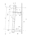
図8は、従来の旅客搭乗橋の概略平面図である。 FIG. 8 is a schematic plan view of a conventional passenger boarding bridge.
この旅客搭乗橋は、ターミナルビルの乗降口に接続されて鉛直回転軸CL1の回りに水平回転自在に支持されたロタンダ4と、基端がロタンダ4に俯仰自在に接続されて伸縮自在に構成されたトンネル部5と、トンネル部5の先端に設けられて回転軸CL2を中心に回転自在なキャブ6と、トンネル部5の先端寄りに設けられてトンネル部5を支持するドライブコラム8とを備えている。トンネル部5は、複数のトンネル5a、5bがテレスコピック式に嵌合されて伸縮自在に構成されている。
This passenger boarding bridge consists of a Rotanda 4 that is connected to the entrance of the terminal building and supported horizontally around the vertical rotation axis CL1 and a base end that is connected to the Rotanda 4 in an up-and-down manner and can be expanded and contracted. It is provided with a
ドライブコラム8には、トンネル部5を上下移動させる昇降機構10が設けられている。昇降機構10によってトンネル部5を上下移動させることにより、トンネル部5はロタンダ4を基端として上下方向に揺動運動することができる。また、ドライブコラム8の下部には、各々独立に正逆回転駆動できる2つの駆動輪9を有する走行部12が設けられている。走行部12は、2つの駆動輪9の回転駆動によって前進走行及び後退走行が自在に構成されるとともに、走行部12(2つの駆動輪9)の中心点を通る回転軸CL3の回りに正逆回転自在に構成されている。
The
また、旅客搭乗橋には、ロタンダ4の回転角度θRを検出する角度センサ(ロタンダ用角度センサ)と、トンネル部5に対するキャブ6の回転角度φCを検出する角度センサ(キャブ用角度センサ)と、トンネル部5に対する走行部12の回転角度φWを検出する角度センサ(走行部用角度センサ)とが設けられている。さらに、水平面に対するトンネル部5の傾斜角度β(図2参照)を測定する傾斜角度測定手段と、ロタンダ4の中心点(回転軸CL1上の位置)から走行部12の中心点までの水平距離(ロタンダ−走行部間水平距離)LWを測定する水平距離測定手段が設けられている。これらの傾斜角度測定手段および水平距離測定手段は、それぞれ、昇降機構10によるトンネル部5の昇降量を測定する距離計およびトンネル部5の長さを測定する距離計等で構成されている。Further, the passenger boarding bridge, an angle sensor for detecting an angle sensor for detecting the rotation angle theta R of rotunda 4 (rotunda for angle sensor), the rotation angle phi C cab 6 for the tunnel portion 5 (an angle sensor cab) And an angle sensor (angle sensor for the traveling portion) that detects the rotation angle φ W of the
また、旅客搭乗橋において、各部の位置を算出するために、図8に示すようなXYZ直交座標系を用いる。すなわち絶対座標として、ロタンダ4の回転軸CL1とエプロン平面との交点を原点(0,0,0)にして、図8に示すようにX軸、Y軸、Z軸(上下方向に延びる軸)をとる。 Further, in the passenger boarding bridge, an XYZ Cartesian coordinate system as shown in FIG. 8 is used to calculate the position of each part. That is, as absolute coordinates, the intersection of the rotation axis CL1 of the Rotanda 4 and the apron plane is set as the origin (0,0,0), and as shown in FIG. 8, the X-axis, Y-axis, and Z-axis (axis extending in the vertical direction) Take.
このような旅客搭乗橋を、例えば、図8に示す待機位置からキャブ6を航空機3に装着する装着位置までの移動を自動制御する場合、走行部12の制御は次のように行われる。ここで、走行部12の待機位置をP3とし、移動先の目標位置(例えば装着位置)をP31とする。走行部12を、その待機位置P3から目標位置P31への移動を自動制御する場合、制御装置(図示せず)は、まず、走行部12の走行方向が待機位置P3から目標位置P31に向かう方向となるように左右の駆動輪9をその場で逆回転させて駆動輪9の向きを修正する(図8ではこの修正後の駆動輪9の状態が示されている)。この後、待機位置P3から目標位置P31に向かって走行部12を直進走行させるようにしている。
When the movement of such a passenger boarding bridge is automatically controlled, for example, from the standby position shown in FIG. 8 to the mounting position where the
このように走行部12を直進走行させる場合に、左右の駆動輪9の回転数(回転速度)を等しくしたとしても、実際には、路面の傾斜等の状態、左右重量のアンバランス等によって、直進走行させることはできない。
When the traveling
そこで、走行中には、2つの各駆動輪9の回転速度を調整するようにしている。例えば、走行中において、所定周期で逐次、ロタンダ用角度センサで検出されるロタンダ4の回転角度θRと、水平距離測定手段で測定されるロタンダ−走行部間水平距離LWとに基づいて、走行部12の中心点(回転軸CL3上の所定位置)の現在位置(座標)を算出し、この算出された現在位置と予定現在位置との誤差(位置誤差)を算出する。さらに、走行部12の現在の走行方向を示す走行角度を算出し、この算出された現在の走行角度と走行目標方向を示す角度との誤差(方向角度誤差)を算出する。そしてこれらの誤差が小さくなるように2つの各駆動輪9の回転速度を調整するフィードバック制御を行うようにしている。Therefore, the rotation speeds of the two
ここで、予定現在位置とは、待機位置P3から目標位置P31に向かう直線状の経路からなる走行目標経路R1上において、予定された走行速度から算出される現在時点における位置である。また、走行目標方向とは、待機位置P3から目標位置P31に一直線に向かう方向であり、走行目標経路R1の延伸方向と同方向である。 Here, the planned current position is a position at the current time calculated from the planned traveling speed on the traveling target route R1 consisting of a linear route from the standby position P3 to the target position P31. The travel target direction is a direction that goes straight from the standby position P3 to the target position P31, and is the same direction as the extension direction of the travel target path R1.
走行中のある時点tにおけるロタンダ−走行部間水平距離LWをLWt、ロタンダ4の回転角度θRをθRtとすると、同時点tにおける走行部12の中心点の現在位置座標(Xt,Yt)は次式で算出される。
Xt = LWt・cosθRt
Yt = LWt・sinθRt
また、同時点tにおける走行部12の回転角度φWをφWtとし、同時点tにおける走行部12の走行方向を示す走行角度θWをθWtとすると、走行角度θWtは、
θWt=θRt+φWtとして算出される。Assuming that the horizontal distance LW between the rotunda and the traveling portion at a certain time point t during traveling is LW t and the rotation angle θ R of the rotunda 4 is θ Rt , the current position coordinates (X t ,) of the center point of the
X t = LW t · cosθ Rt
Y t = LW t · sin θ Rt
Further, assuming that the rotation angle φ W of the
It is calculated as θ Wt = θ Rt + φ Wt.
なお、走行部12の走行方向を示す走行角度θWは、走行方向が特定方向(例えばX軸の正方向)となす角度(エプロン平面上における絶対角度)であり、
θW=θR+φWの関係がある。 The traveling angle θ W indicating the traveling direction of the
There is a relationship of θ W = θ R + φ W.
また、走行目標角度θTは、走行目標方向(走行目標経路R1の延伸方向)が特定方向(例えばX軸の正方向)となす角度(エプロン平面上における絶対角度)である。図8では、走行部12の走行角度θWが、走行目標角度θTと等しくなっている場合が示されている。Further, the traveling target angle θ T is an angle (absolute angle on the apron plane) formed by the traveling target direction (extending direction of the traveling target path R1) and a specific direction (for example, the positive direction of the X axis). FIG. 8 shows a case where the traveling angle θ W of the
そして、上記のフィードバック制御では、所定周期で算出されるある時点tの実際の現在位置座標(Xt,Yt)と、走行目標経路R1を予定通り走行する場合の同時点tにおける予定現在位置座標(X0t,Y0t)とに基づいて、これらの誤差(位置誤差)が小さくなるように、すなわち実際の位置が予定の位置に近づくように2つの駆動輪9の回転速度を調整する。より具体的な例としては、上記の位置誤差を、走行目標角度θTで示される走行目標方向における第1の位置誤差と、走行目標方向と直交する方向における第2の位置誤差とに分けて、各々の位置誤差が小さくなるように、2つの駆動輪9の回転速度を調整する。Then, in the above feedback control, the actual current position coordinates (X t , Y t ) at a certain time point t calculated in a predetermined cycle and the planned current position at the simultaneous point t when traveling on the travel target route R1 as scheduled. Based on the coordinates (X 0t , Y 0t ), the rotation speeds of the two
さらに、上記のフィードバック制御では、実際の走行角度θWtと走行目標角度θTとの誤差(方向角度誤差)が小さくなるように2つの駆動輪9の回転速度を調整する。Further, in the above feedback control, the rotation speeds of the two
この場合、第1の位置誤差と第2の位置誤差と方向角度誤差との3つの誤差に対して、例えば重み付けして2つの駆動輪9の回転速度を調整するフィードバック制御を行うようにしている。
In this case, feedback control is performed to adjust the rotation speeds of the two
上記のフィードバック制御が理想的に行われて制御偏差がないと仮定すると、制御計算上では走行部12の中心点は走行目標経路R1上を移動することになる。すなわち、制御装置では、走行部12の中心点は走行目標経路R1上を移動していると認識している。しかし、実際の走行経路は、走行目標経路R1からずれたものになる。これは、ロタンダ4の回転角度を検出するロタンダ用角度センサの直線性(linearity)や分解能による測定誤差が主な要因となっている。
Assuming that the above feedback control is ideally performed and there is no control deviation, the center point of the traveling
図9(A)は、ロタンダ用角度センサによる測定角度と実際の角度(真の角度)との関係の一例を示す図である。この例では、測定角度が角度θR0のときを走行開始時として、測定角度が例えばθR1,θR2,θR3のときには、実際の角度との間に測定誤差ΔθR1,ΔθR2,ΔθR3が生じている。FIG. 9A is a diagram showing an example of the relationship between the measurement angle by the rotunda angle sensor and the actual angle (true angle). In this example, when the measurement angle is the angle θ R0 as the start of travel, and when the measurement angles are, for example, θ R1 , θ R2 , and θ R3 , the measurement errors are between the actual angles Δθ R1 , Δθ R2 , and Δθ R3. Is occurring.
図9(B)は、図9(A)のように測定角度と実際の角度との間に誤差ΔθR1,ΔθR2,ΔθR3で示されるような測定誤差があるときの走行部12の駆動輪9の走行経路の一例を示す図である。図9(B)では、ハッチングの入っていない長方形が制御計算上の左右の駆動輪9の位置であり、ハッチングの入った長方形が実際の駆動輪9の位置である。この例では、走行開始時(待機位置)のときには、測定角度と実際の角度はともにθR0であり、制御計算上の駆動輪9の位置と実際の駆動輪9の位置とは重なって同一であるが、実際には誤差がある場合もある。9 (B) shows the driving of the
前述のように、直線状の走行目標経路R1に対して、フィードバック制御が理想的に行われて、制御計算上では走行部12の中心点が走行目標経路R1上を移動している場合でも、ロタンダ用角度センサの測定誤差ΔθRによって実際の走行経路R2は走行目標経路R1からずれた経路になっている。As described above, even when feedback control is ideally performed for the linear travel target route R1 and the center point of the
走行中のある時点における制御計算上の走行位置(走行部12の中心点の位置)と実際の走行位置との位置ずれ量は、同時点におけるロタンダ−走行部間水平距離LWと測定誤差ΔθRとの積に略比例する。ここで、ロタンダ−走行部間水平距離LWはおよそ10〜45mと比較的大きいので、測定誤差ΔθRに起因する位置ずれ量は大きくなる。The amount of misalignment between the running position (the position of the center point of the running part 12) in the control calculation at a certain point during running and the actual running position is the horizontal distance LW between the Rotander and the running part at the same point and the measurement error Δθ R. It is roughly proportional to the product of. Here, since the horizontal distance LW between the rotunda and the traveling portion is relatively large, about 10 to 45 m, the amount of misalignment due to the measurement error Δθ R becomes large.
よって、図9(A)に示すように測定誤差ΔθRは変動しており、測定誤差ΔθRの絶対値が大きいときに走行部12が例えば装着位置等の目標位置に到達した場合には、目標とする装着位置からの位置ずれ量が大きくなり、航空機3に対してキャブ6の正常な装着が行えなくなる虞が生じるという問題がある。Therefore, as shown in FIG. 9A, the measurement error Δθ R fluctuates, and when the traveling
本発明は上記のような課題を解決するためになされたもので、走行部による移動開始位置から移動先の位置への直進走行を良好に行うことが可能になる旅客搭乗橋の走行制御方法を提供することを目的としている。 The present invention has been made to solve the above-mentioned problems, and provides a traveling control method for a passenger boarding bridge that enables a traveling unit to satisfactorily travel straight from a moving start position to a moving destination position. It is intended to be provided.
上記目的を達成するために、本発明のある態様に係る旅客搭乗橋の走行制御方法は、ターミナルビルに接続され、鉛直軸線まわりに正逆回転自在なロタンダと、基端が前記ロタンダに俯仰自在に接続されるとともに長手方向に伸縮自在に構成されたトンネル部と、前記トンネル部の先端に回転自在に設けられたキャブと、前記トンネル部または前記キャブに取り付けられ、前記トンネル部または前記キャブを昇降させる昇降機構と、前記昇降機構の下方に取り付けられて地面を走行し、中心点を通る軸線まわりに正逆回転することにより走行方向を変更可能に構成された走行部と、前記ロタンダの回転角度を検出するロタンダ用角度センサと、前記走行部の回転角度を検出する走行部用角度センサと、前記鉛直軸線から前記走行部の前記中心点までの水平距離を測定するための水平距離測定手段と、水平面に対する前記トンネル部の傾斜角度を測定するための傾斜角度測定手段と、を備えた旅客搭乗橋の走行制御方法であって、前記キャブを航空機の乗降部に装着する際、前記走行部が移動開始位置にあるときに、前記キャブから視た前記乗降部の位置を示す相対位置情報を算出するステップと、前記移動開始位置から前記キャブを前記乗降部に装着するために前記走行部を移動させる移動先の位置までの距離が、前記鉛直軸線から前記移動開始位置における前記走行部の中心点までの水平距離よりも短い所定の状態の場合に、前記移動開始位置における前記走行部の位置情報と前記乗降部の相対位置情報とに基づいて前記移動先の位置情報を算出するステップと、前記移動開始位置から前記移動先の位置へ一直線に向かう方向と特定方向とのなす角度である走行目標角度を算出するステップと、前記走行部を前記移動開始位置から前記移動先の位置へ向けて走行させ、この走行中において、所定周期で前記走行部の現在の走行方向と前記特定方向とのなす角度である走行角度を算出し、前記走行角度が前記走行目標角度を維持するようにのみ前記走行部を制御する走行ステップと、を有し、前記移動先の位置情報を算出するステップにおいて、前記移動開始位置の位置情報は、前記水平距離測定手段で測定される前記鉛直軸線から前記走行部の中心点までの水平距離と前記ロタンダ用角度センサで測定される前記ロタンダの回転角度と前記傾斜角度測定手段で測定される前記傾斜角度とに基づいて算出され、前記走行ステップにおいて、前記走行角度は、前記走行部用角度センサで測定される前記走行部の回転角度と前記ロタンダ用角度センサで測定される前記ロタンダの回転角度とに基づいて算出される。 In order to achieve the above object, the traveling control method of the passenger boarding bridge according to an aspect of the present invention is a rotanda that is connected to a terminal building and can rotate forward and reverse around the vertical axis, and the base end can be raised and lowered by the rotanda. A tunnel portion connected to the tunnel portion and configured to be stretchable in the longitudinal direction, a cab rotatably provided at the tip of the tunnel portion, and the tunnel portion or the cab attached to the tunnel portion or the cab. An elevating mechanism for elevating and lowering, a traveling unit mounted below the elevating mechanism, traveling on the ground, and rotating forward and reverse around an axis passing through a center point to change the traveling direction, and rotation of the rotanda. A Rotanda angle sensor that detects an angle, a traveling unit angle sensor that detects the rotation angle of the traveling unit, and a horizontal distance measuring means for measuring the horizontal distance from the vertical axis to the center point of the traveling unit. It is a traveling control method of a passenger boarding bridge provided with an inclination angle measuring means for measuring an inclination angle of the tunnel portion with respect to a horizontal plane, and when the cab is attached to an aircraft boarding / alighting portion, the traveling portion Is in the movement start position, a step of calculating relative position information indicating the position of the boarding / alighting part as seen from the cab, and the traveling part for mounting the cab on the boarding / alighting part from the movement start position. When the distance to the position of the moving destination to be moved is shorter than the horizontal distance from the vertical axis to the center point of the traveling portion at the moving start position, the position of the traveling portion at the moving start position. A step of calculating the position information of the movement destination based on the information and the relative position information of the boarding / alighting portion, and an angle formed by a direction from the movement start position to the position of the movement destination in a straight line and a specific direction. The step of calculating the target angle and the traveling unit are traveled from the moving start position to the moving destination position, and during this traveling, the current traveling direction of the traveling unit and the specific direction are set in a predetermined cycle. In a step of calculating a traveling angle which is an angle to be formed and controlling the traveling portion only so that the traveling angle maintains the traveling target angle, and calculating the position information of the moving destination. The position information of the movement start position includes the horizontal distance from the vertical axis measured by the horizontal distance measuring means to the center point of the traveling portion, the rotation angle of the rotor and the inclination measured by the angle sensor for the rotor. Calculated based on the tilt angle measured by the angle measuring means, and the running horizontal The traveling angle is calculated based on the rotation angle of the traveling portion measured by the traveling portion angle sensor and the rotation angle of the rotanda measured by the rotanda angle sensor.
この走行制御方法によれば、走行部が移動開始位置において、移動開始位置から移動先の位置までの距離(距離A)が、ロタンダの回転中心(鉛直軸線)から走行部の中心点までの水平距離(距離B)よりも短い所定の状態の場合に、移動先の位置情報を算出し、走行部の走行中において、所定周期で走行角度を算出し、走行角度が走行目標角度を維持するようにのみ走行部を制御するようにしている。ここで、ロタンダ用角度センサの測定誤差が大きく影響して算出される走行部の現在位置と走行目標経路(移動開始位置と移動先の位置とを一直線で結ぶ経路)上の走行部の予定現在位置との位置誤差を考慮しないで、上述のように、距離Aが距離Bよりも短い場合において走行角度のみを考慮して制御することにより、走行部の走行目標経路からの位置ずれ量を小さくして移動開始位置から移動先の位置への直進走行を良好に行うことが可能になる。なお、移動開始位置は、それ以前の何らかの手段または原因による移動後もしくは移動途中の位置でもよい。 According to this traveling control method, when the traveling unit is in the moving start position, the distance (distance A) from the moving start position to the moving destination position is horizontal from the rotation center (vertical axis) of the Rotanda to the center point of the traveling unit. In the case of a predetermined state shorter than the distance (distance B), the position information of the moving destination is calculated, the traveling angle is calculated at a predetermined cycle while the traveling unit is traveling, and the traveling angle maintains the traveling target angle. The traveling unit is controlled only by the plumb bob. Here, the current position of the traveling unit and the planned current position of the traveling unit on the traveling target path (the route connecting the moving start position and the moving destination position in a straight line) calculated by the measurement error of the Rotanda angle sensor. As described above, when the distance A is shorter than the distance B, the position deviation from the travel target path of the traveling portion is reduced by controlling only the traveling angle without considering the positional error from the position. Therefore, it becomes possible to satisfactorily travel straight from the movement start position to the movement destination position. The movement start position may be a position after or during the movement by some means or cause before that.
前記移動先の位置は、前記キャブが前記乗降部に装着されるときの前記走行部の位置であるようにしてもよい。 The position of the moving destination may be the position of the traveling portion when the cab is mounted on the getting on / off portion.
前記相対位置情報を算出するステップは、前記キャブに取り付けられたカメラで撮影される前記乗降部の画像に基づいて前記乗降部を検知し当該乗降部の前記相対位置情報を算出するようにしてもよい。 In the step of calculating the relative position information, the boarding / alighting part is detected based on the image of the boarding / alighting part taken by the camera attached to the cab, and the relative position information of the boarding / alighting part is calculated. Good.
前記走行部は、前記走行部の中心点を挟んで互いに平行に配置されて個々に独立して回転駆動可能な2つの駆動輪を有するよう構成されており、前記走行ステップは、前記2つの駆動輪の各々の回転速度を調整することにより前記走行部を制御するようにしてもよい。 The traveling unit is configured to have two drive wheels that are arranged parallel to each other with the center point of the traveling unit and capable of independently rotating and driving, and the traveling step is configured to have the two driving wheels. The traveling portion may be controlled by adjusting the rotation speed of each of the wheels.
前記移動先の位置情報を算出するステップにおける前記所定の状態は、前記移動開始位置から前記移動先の位置までの距離が、前記トンネル部が最も収縮している場合の前記鉛直軸線から前記走行部の中心点までの水平距離よりも短い所定の距離以下の状態であるとしてもよい。 In the predetermined state in the step of calculating the position information of the moving destination, the distance from the moving start position to the moving destination position is from the vertical axis when the tunnel portion is most contracted to the traveling portion. It may be in a state of a predetermined distance or less, which is shorter than the horizontal distance to the center point of.
本発明は、以上に説明した構成を有し、走行部による移動開始位置から移動先の位置への直進走行を良好に行うことが可能になる旅客搭乗橋の走行制御方法を提供することができるという効果を奏する。 INDUSTRIAL APPLICABILITY The present invention can provide a traveling control method for a passenger boarding bridge, which has the configuration described above and enables the traveling unit to satisfactorily travel straight from a moving start position to a moving destination position. It plays the effect.
以下、本発明の好ましい実施の形態を、図面を参照しながら説明する。なお、以下では全ての図面を通じて同一又は相当する要素には同一の参照符号を付して、その重複する説明を省略する。また、本発明は、以下の実施形態に限定されない。 Hereinafter, preferred embodiments of the present invention will be described with reference to the drawings. In the following, the same or corresponding elements will be designated by the same reference numerals throughout the drawings, and duplicate description thereof will be omitted. Further, the present invention is not limited to the following embodiments.
(実施形態)
図1は、本実施形態に係る旅客搭乗橋の一例を示す概略平面図である。図2は、図1に示す旅客搭乗橋を側方から視た概略図である。また、図3は、航空機に装着されるキャブ先端部分を正面(航空機側)から視た図である。図4は、操作盤等の一例を示す図である。(Embodiment)
FIG. 1 is a schematic plan view showing an example of a passenger boarding bridge according to the present embodiment. FIG. 2 is a schematic view of the passenger boarding bridge shown in FIG. 1 as viewed from the side. Further, FIG. 3 is a view of the tip of the cab mounted on the aircraft as viewed from the front (aircraft side). FIG. 4 is a diagram showing an example of an operation panel and the like.
旅客搭乗橋1は、本実施形態に係る旅客搭乗橋の走行制御方法を適用することができる。この旅客搭乗橋1は、空港のターミナルビル2の乗降口2aに接続された水平回転自在なロタンダ(基部円形室)4と、基端がロタンダ4に俯仰自在に接続されて長手方向に伸縮自在に構成されたトンネル部5と、トンネル部5の先端に正逆回転自在に設けられたキャブ(先端部円形室)6と、ドライブコラム8とを備えている。
The
ロタンダ4は、支柱7によって回転軸(鉛直軸線)CL1の回りに正逆回転自在に支持されている。
The rotunda 4 is supported by a
トンネル部5は、ターミナルビル2の乗降口2aと航空機3のドア3aとをつなぐ連絡通路を形成する伸縮自在な筒状体であり、複数のトンネル5a,5bがテレスコピック式(入れ子式)に嵌合されて長手方向に伸縮自在に構成され、トンネル部5はその全体が伸縮するようになっている。なお、ここでは、2つのトンネル5a,5bによって構成されたトンネル部5が例示されているが、トンネル部5は2つ以上の複数のトンネルによって構成されていればよい。また、トンネル部5の基端部は、ロタンダ4に、水平回転軸CL4(図2)の回りに揺動自在(上下に揺動自在)に接続されることにより、ロタンダ4に俯仰自在に接続されている。
The
また、トンネル部5の先端寄り部分(最も先端側のトンネル5b)には、支持脚としてドライブコラム8が設けられている。ドライブコラム8には、キャブ6及びトンネル部5を上下移動(昇降)させる昇降機構10が設けられている。この昇降機構10によってトンネル部5を上下移動させることにより、キャブ6及びトンネル部5は、ロタンダ4を基端として上下方向に揺動運動することができる。
Further, a
また、ドライブコラム8には、昇降機構10の下方に、一対の駆動輪9を有する走行部12が設けられている。走行部12は、2つの駆動輪9の回転駆動によって前進走行及び後退走行が可能に構成されている。また、走行部12は、舵角がトンネル部5の長手方向に対して、−90゜〜+90゜の範囲内で変更可能なように、走行部12(2つの駆動輪9)の中心点を通り上下方向に延びる回転軸(中心軸線)CL3の回りに正逆回転自在に構成され、走行方向を変更可能である。つまり、2つの駆動輪9は、走行部12の中心点を挟んで互いに平行に配置されて個々に独立して回転駆動可能である。また、2つの駆動輪9は、これらの中心点(走行部12の中心点)を通る走行方向(ロール軸)に対してローリングできるよう揺動可能に構成されている。走行部12(駆動輪9)が地面を走行することにより、トンネル部5を回転軸CL1まわりに回転させるとともにトンネル部5を伸縮させることができる。なお、ドライブコラム8は、トンネル5bではなくキャブ6に設けられてあってもよい。
Further, the
キャブ6は、トンネル部5の先端に設けられており、図示しない回転機構によってキャブ6の床面に垂直な回転軸CL2の回りに正逆回転自在に構成されている。このようにキャブ6はトンネル部5の先端に取り付けられているので、ドライブコラム8の昇降機構10によって、キャブ6もトンネル部5とともに、ロタンダ4を基端として上下方向に揺動運動することができる。
The
また、図1、図3に示すように、キャブ6の先端部分の床面よりやや上に航空機3のドア3aを撮影するためのドア撮影用カメラ(乗降部撮影用カメラ)21が設置されている。このカメラ21には、例えばIPカメラが用いられており、本例ではキャブ6に対して設置位置および撮影方向が固定されているが、キャブに対して撮影方向を制御したり変更したりできるものであってもよく、画角を調整できるものであってもよい。また、キャブ6の先端部の床62の先端に設けられたバンパー61の左右方向に並んで、キャブ6と航空機3との間の距離(例えば、図1に示す距離RA)を検出する距離センサ22,23(例えばレーザー距離計)が複数(この例では2つ)取り付けられている。なお、本例では距離センサ22,23の計測方向は固定されているが、計測方向を制御したり変更したりできるよう構成されていてもよい。
Further, as shown in FIGS. 1 and 3, a door photographing camera (camera for getting on and off part) 21 for photographing the
また、図3に示すように、キャブ6の先端部には、前後方向に伸縮可能な蛇腹部63が設けられている。図3には、蛇腹部63の前端部分で航空機3と当接する門型の当接部分が図示されている。
Further, as shown in FIG. 3, a
さらに、図4に示すように、旅客搭乗橋1には、ロタンダ4の回転角度θR(図1)を検出するロタンダ用角度センサ24と、トンネル部5に対するキャブ6の回転角度φC(図1)を検出するキャブ用角度センサ25と、トンネル部5に対する走行部12の回転角度φW(図1)を検出する走行部用角度センサ26と、傾斜角度測定手段27と、水平距離測定手段28とが、適宜な位置に設けられている。傾斜角度測定手段27および水平距離測定手段28は、それぞれ、昇降機構10によるトンネル部5の昇降量(上下移動量)を測定する距離計およびトンネル部5の長さを測定する距離計等で構成されているが、このような構成に限らず、傾斜角度を直接測定するセンサや、水平距離を直接測定するセンサであってもよい。Further, as shown in FIG. 4, the
傾斜角度測定手段27は、水平面に対するトンネル部5の傾斜角度β(図2参照)を測定する。この傾斜角度測定手段27では、トンネル部5が水平状態であるときの傾斜角度βを0とし、この水平状態のときよりもトンネル部5の先端及びキャブ6が低い位置になるときの傾斜角度βを負の値として算出し、水平状態のときよりもトンネル部5の先端及びキャブ6が高い位置になるときの傾斜角度βを正の値として算出するよう構成されている。よって、トンネル部5が図2で示された傾斜状態の場合には、傾斜角度βは負の値(β<0)になっている。
The inclination angle measuring means 27 measures the inclination angle β (see FIG. 2) of the
また、水平距離測定手段28は、ロタンダ4の中心点(回転軸CL1上の位置)から走行部12の中心点(回転軸CL3上にある一対の駆動輪9の中心点)までの水平距離であるロタンダ−走行部間水平距離LWを測定することができる。このロタンダ−走行部間水平距離LWは、回転軸CL1から走行部12の中心点までの距離(水平距離)である。
Further, the horizontal distance measuring means 28 measures the horizontal distance from the center point of the Rotanda 4 (position on the rotation axis CL1) to the center point of the traveling portion 12 (center point of the pair of
なお、図1では、トンネル部5が水平状態(図2の傾斜角度β=0の状態)で、キャブ6の先端部分が航空機3の方を向いた状態が示されている。一方、図2では、トンネル部5が傾斜角度βにて傾斜した状態で、キャブ6の先端部分がトンネル部5の伸長方向と同方向を向いた状態が示されている。
Note that FIG. 1 shows a state in which the
キャブ6の内部には、図4に示すような操作盤31が設けられている。操作盤31には、昇降機構10によるトンネル部5及びキャブ6の昇降や、キャブ6の回転等を操作するための各種操作スイッチ33の他、駆動輪9を操作するための操作レバー32及び表示装置34が設けられている。操作レバー32は、多方向の自由度をもったレバー状入力装置(ジョイスティック)によって構成されている。
An
また、制御装置50は、操作盤31と相互に電気回路で接続され、操作スイッチ33や操作レバー32の操作に基づく情報(操作情報)が入力されるとともに、カメラ21で撮影される画像データ、各センサ22〜26の出力信号及び測定手段27,28の測定値等が入力されて、旅客搭乗橋1の動作を制御するとともに、表示装置34に表示される情報等を出力する。
Further, the
なお、制御装置50には、CPU等の演算処理部と、ROM、RAM等の記憶部とを有している。記憶部には、旅客搭乗橋1を動作させるための制御プログラム及び当該動作に必要な情報が予め記憶されており、演算処理部が制御プログラムを実行することにより、旅客搭乗橋1の各部の動作(走行部12の2つの駆動輪9、昇降機構10及びキャブ6の回転機構等の動作)の制御等を行う制御部として機能するとともに、ドア位置算出部(乗降位置算出部)51等として機能する。なお、旅客搭乗橋1の動作中に記憶される情報も記憶部に記憶される。制御装置50は、例えば、キャブ6または最も先端側のトンネル5b等に設けられている。
The
次に、旅客搭乗橋1の動作の一例について説明する。この旅客搭乗橋1の動作は、制御装置50の制御によって実現される。図5は、旅客搭乗橋1のキャブ6を航空機3へ装着する時の動作の一例を示すフローチャートである。
Next, an example of the operation of the
旅客搭乗橋1を制御する際、制御装置50は、図1に示すようなXYZ直交座標系を用いる。すなわち絶対座標として、ロタンダ4の回転軸CL1とエプロン平面EP(図2)との交点を原点(0,0,0)にして、X軸、Y軸、Z軸(上下方向に延びる軸)をとり、旅客搭乗橋1の各部の位置座標をあらわす。
When controlling the
旅客搭乗橋1は、航空機3がエプロン(所定の駐機場所)に到着して停止する前には、図1の実線で示された位置である待機位置で待機している。この待機位置において、航空機3の乗降部(ドア3a)がカメラ21の撮影視野に入らない場合、もしくは2つの距離センサ22,23の検出範囲外となる場合は、航空機3の停止後に別途、旅客搭乗橋1を作動させ、航空機3の乗降部(ドア3a)がカメラ21の撮影視野に入り、かつ2つの距離センサ22,23の検出範囲内となる位置へキャブ6を回転したり走行部12を駆動したりする。そして、この位置を新たに移動開始位置とすればよいので、以降では簡単のため、この待機位置で航空機3の乗降部(ドア3a)がカメラ21の撮影視野に入り、かつ2つの距離センサ22,23の検出範囲内である場合(すなわち、待機位置が移動開始位置である場合)を説明する。
The
なお、カメラ21の撮影方向や画角が調整可能な場合は、航空機3の乗降部(ドア3a)が撮影視野に入るようこれらを調整してもよく、距離センサ22,23の計測方向が調整可能な場合は、航空機3を検出すべく距離センサの計測方向を調整してもよい。
If the shooting direction and angle of view of the
旅客搭乗橋1の待機位置は、旅客搭乗橋1を航空機3の乗降部(ドア3a)に装着する際に移動の起点となる移動開始位置である。旅客搭乗橋1が航空機3の乗降部に装着される際には、待機位置から移動を開始してキャブ6が乗降部に装着される。そして、キャブ6が乗降部から離脱したときには待機位置に戻って停止し、次の航空機の乗降部への装着動作が開始されるまで、待機位置で待機している。
The standby position of the
なお、キャブ6が航空機3から離脱して待機位置へ戻る際に、走行部12の目標とする待機位置における走行部12の中心位置P3の座標(走行部12の待機位置の位置座標)は、予め制御装置50に記憶されている。また、図2に示されるように、キャブ6の中心位置P1から先端位置P2までの距離LB(所定値)と、キャブ6の中心位置P1からドライブコラム8の取付位置までの距離LD(所定値)と、ロタンダ4の中心点からトンネル部5との接続部(水平回転軸CL4の位置)までの距離LR(所定値)と、上記接続部の高さHR(所定値)と、駆動輪9の半径HW(所定値)とは、予め制御装置50に記憶されている。
When the
例えば、キャブ6の中心位置(P1)は、キャブ6の中心点(回転軸CL2上の所定位置)の位置座標で表される。待機位置におけるキャブ6の中心位置P1の座標は、例えば、トンネル部5の傾斜角度βと、ロタンダ−走行部間水平距離LWと、ロタンダ4の回転角度θRと、ロタンダ4の中心点からトンネル部5との接続部までの距離LRと、キャブ6の中心位置P1からドライブコラム8の取付位置までの距離LDと、を用いて算出できる。また、キャブ6の先端位置P2の座標は、キャブ6の中心位置P1と、キャブ6の中心位置P1から先端位置P2までの距離LBと、キャブ6の回転角度φCと、ロタンダ4の回転角度θRと、トンネル部5の傾斜角度βとを用いて算出できる。また、走行部12の中心位置P3のX,Y座標は、ロタンダ−走行部間水平距離LWと、ロタンダ4の回転角度θRとを用いて算出できる。また、走行部12の中心位置P3のZ座標は、駆動輪9の半径HW(図2)の値からなる一定値である。For example, the center position (P1) of the
また、図1の二点鎖線で示された旅客搭乗橋1は、キャブ6が航空機3の乗降部に装着された状態となる装着位置にある状態を示している。このとき、キャブ6の先端位置(P5)が航空機3の乗降部に接した状態となっている。
Further, the
また、航空機3の正規の停止位置は、航空機3の機軸が機軸ライン(機体誘導ライン)AL上で、かつ、Y軸方向において定められた所定の位置である。航空機3は、正規の停止位置を目標にして停止されるが、実際の停止位置は正規の停止位置とはずれが生じる場合がある。なお、機軸ラインALは、エプロンに描かれている。図1では、航空機3の機軸が機軸ラインAL上にある状態が示されている。
Further, the regular stop position of the
この旅客搭乗橋1では、航空機3に装着されるまでの動作が制御装置50による制御によって自動で行われる。この自動制御は、以下のようにして行われる。なお、以下では、位置Pn(nは整数)のX座標をXn、Y座標をYn、Z座標をZnで表す。そして、X座標値、Y座標値、Z座標値は、それぞれ、ロタンダ4の回転軸CL1の位置である原点(0,0,0)からの距離(例えば単位〔mm〕)を示す。この例では、X座標値は図1において原点(0,0,0)より右側を正の値とし、左側を負の値とする。また、Y座標値は原点(0,0,0)に対しターミナルビル2と反対方向を正の方向とし、Z座標値は原点(0,0,0)より上方向を正の方向とする。
At the
図5に示すように、ステップS11において、操作者が操作盤31の機種選択ボタン(図示せず)を押すことにより航空機3の機種の選択が行われ、この選択された機種情報が制御装置50に入力される。
As shown in FIG. 5, in step S11, the operator presses the model selection button (not shown) on the
次に、操作者が操作盤31のスタートボタン(操作スイッチ33の一つ)を押すことにより、以下の自動制御が開始される。なお、本実施形態では安全性の向上のために、スタートボタンは操作者がボタンを押しているときにのみON状態となる方式のボタン、すなわちいわゆるデッドマンスイッチ方式のボタンによって形成されている。従って、操作者がボタンから手を離すと、自動制御は強制的に中止されるようになっている。
Next, when the operator presses the start button (one of the operation switches 33) on the
上記のスタートボタンが押されると、制御装置50は、ステップS12において、旅客搭乗橋1を目標位置へ移動させるための制御量を演算する。具体例としては、以下の(1)〜(3)で示される。また、この場合のフローチャートの一例を図6に示す。なお、図6に示される各ステップの順序は、図6に示される順序に限定されるものではない。ここで、目標位置は、図1の二点鎖線で示されている装着位置である。
When the start button is pressed, the
(1)走行部12の回転角度、走行目標距離及び走行目標角度の演算(図6のステップS51〜S58)
ここでは、キャブ6の中心位置を、待機位置にある現在位置P1(X1,Y1,Z1)からキャブ6が航空機3のドア3aに装着される目標位置P6(X6,Y6,Z6)へ移動させるための、走行部12(駆動輪9)の回転角度、走行目標距離及び走行目標角度を演算する。(1) Calculation of the rotation angle, the target travel distance, and the target travel angle of the traveling unit 12 (steps S51 to S58 in FIG. 6).
Here, the center position of the
制御装置50は、ステップS51では、待機位置にある現在の駆動輪9の中心位置(走行部12の中心位置)P3のXY座標(X3,Y3)を次式により算出する。
X3=LW×cosθR
Y3=LW×sinθR
ここで、ロタンダ−走行部間水平距離LWは、待機位置のときの水平距離測定手段28に基づく値、走行部12の回転角度θRは、待機位置のときのロタンダ用角度センサ24に基づく値である。なお、駆動輪9の中心位置のZ座標は、常に、駆動輪9の半径HWの値からなる所定値であり、不変とする。In step S51, the
X3 = LW × cosθ R
Y3 = LW × sinθ R
Here, the horizontal distance LW between the rotunda and the traveling unit is a value based on the horizontal distance measuring means 28 in the standby position, and the rotation angle θ R of the traveling
次に、制御装置50は、航空機3のドア3aの位置P4(X4,Y4,Z4)を算出するために、ステップS52〜S55を行う。なお、(X4,Y4,Z4)が乗降部(ドア3a)の位置情報である。
Next, the
まず、ステップS52では、現在のキャブ6の中心位置P1(X1,Y1,Z1)を次式により算出する。
X1=LC×cosθR
Y1=LC×sinθR
Z1=(LC−LR)×tanβ+HR
ここで、LCは、図2に示されるように、ロタンダ−キャブ間水平距離であり、ロタンダ4の中心点からキャブ6の中心点までの水平距離である。このロタンダ−キャブ間水平距離LCは、待機位置のときの傾斜角度測定手段27の測定値であるトンネル部5の傾斜角度βと、距離LEと、距離LD(所定値)、距離LR(所定値)とを用いて、次式により算出する。
LC=LR+LF×cosβ=LR+(LE+LD)×cosβ
なお、LFは、図2に示すように、トンネル部5の基端部(水平回転軸CL4の位置)からキャブ6の中心位置P1までの距離であり、LE+LDである。ここで、距離LEは、トンネル部5の基端部(図2の水平回転軸CL4の位置)からドライブコラム8の取付位置までの距離である。この距離LEは、水平距離測定手段28を構成するトンネル部5の長さを測定する距離計の測定値から算出することができる。First, in step S52, the current center position P1 (X1, Y1, Z1) of the
X1 = LC × cosθ R
Y1 = LC × sinθ R
Z1 = (LC-LR) x tanβ + HR
Here, LC is the horizontal distance between the rotunda and the cab, as shown in FIG. 2, and is the horizontal distance from the center point of the rotunda 4 to the center point of the
LC = LR + LF x cosβ = LR + (LE + LD) x cosβ
As shown in FIG. 2, LF is the distance from the base end portion (position of the horizontal rotation axis CL4) of the
次に、ステップS53では、現在のキャブ6の先端位置P2(X2,Y2,Z2)を次式により算出する。なお、回転角度φCは、待機位置のときのキャブ用角度センサ25に基づく値である。
X2=X1+LB×(cosφCcosβcosθR−sinφCsinθR)
Y2=Y1+LB×(cosφCcosβsinθR+sinφCcosθR)
Z2=Z1+LB×(cosφCsinβ)
次に、ステップS54、S55では、制御装置50は、ドア撮影用カメラ21の撮影画像に基づいて航空機3のドア3aを検出し、そのドア3aの位置P4(X4,Y4,Z4)を算出する。Next, in step S53, the current tip position P2 (X2, Y2, Z2) of the
X2 = X1 + LB × (cosφ C cosβ cosθ R − sinφ C sinθ R )
Y2 = Y1 + LB × (cosφ C cosβsinθ R + sinφ C cosθ R)
Z2 = Z1 + LB × (cosφ C sin β)
Next, in steps S54 and S55, the
これについて詳しく説明する。図7は、キャブ6が待機位置でのドア撮影用カメラ21の撮影画像A2の一例を示す概略図である。
This will be described in detail. FIG. 7 is a schematic view showing an example of a photographed image A2 of the
航空機3のドア3aの位置P4の定義はさまざま考えられるが、ここでは画像認識技術によって検出することを考え、ドア3aのペイント部分41の左下側のコーナー部の曲線部分とそのコーナー部から上に延びる直線部分との境界点である基準点p2の位置と定義する。
There are various definitions of the position P4 of the
一般的に、航空機3では、ドア3aが視認できるようにドア3aの輪郭部分にペイントが施されており、本例では、そのペイント部分41の形状に基づいてドア3a及びその基準点p2を検出するようにしている。
Generally, in the
ステップS54では、制御装置50は、上記のようにして、ドア3a及びその位置として、本例では左側の基準点p2の位置をyz座標(y2,z2)で求める。なお、制御装置50は、撮影画像A2において、所定の位置(例えば左上の角部)を原点(0,0)としてyz直交座標系を定めている。撮影画像A2上の任意の点のy座標値及びz座標値は、原点(0,0)から数えたピクセル値で表される。この撮影画像A2において、カメラ21の光軸の座標が(y0,z0)である。
In step S54, the
ステップS55では、制御装置50は、まず、所定の演算式(A)に基づいて、キャブ6から視た乗降部(ドア3a)の位置を示す相対位置情報(dX,dY,dZ)を算出する。この演算式(A)は、距離センサ22,23の測定値と、基準点p2の変位(dy,dz)と、ロタンダ4の回転角度θRと、キャブ6の回転角度φCと、トンネル部5の傾斜角度βとを変数として、相対位置情報(dX,dY,dZ)を算出する式であるが、その際、ステップS11において取得した機種情報に対応する機体特有のデータ(予め制御装置50の記憶部に記憶)を参照してもよい。ここで、基準点p2の変位dyは、基準点p2のy座標値y2とカメラ21の光軸のy座標値y0との差である(dy=y2−y0)。また、基準点p2の変位dzは、基準点p2のz座標値z2とカメラ21の光軸のz座標値z0との差である(dz=z2−z0)。In step S55, the
さらに、ステップS55では、制御装置50は、XYZ直交座標系における航空機3のドア3aの位置P4(X4,Y4,Z4)を、上記相対位置情報(dX,dY,dZ)を用いて次式により算出する。
X4=X2+dX
Y4=Y2+dY
Z4=Z2+dZ
次に、ステップS56では、制御装置50は、航空機3のドア3aの位置P4(X4,Y4,Z4)と、距離センサ22,23の測定値および装着位置オフセット距離等から計算される変位(dX5,dY5,dZ5)に基づいて、目標位置となるときのキャブ6の中心位置P6(X6,Y6,Z6)を、
X6=X4+dX5
Y6=Y4+dY5
Z6=Z4+dZ5
として算出する。なお、装着位置オフセット距離は、ステップS11において取得した機種情報に対応する機体特有のデータ(予め制御装置50の記憶部に記憶)を参照してもよい。Further, in step S55, the
X4 = X2 + dX
Y4 = Y2 + dY
Z4 = Z2 + dZ
Next, in step S56, the
X6 = X4 + dX5
Y6 = Y4 + dY5
Z6 = Z4 + dZ5
Calculate as. The mounting position offset distance may refer to machine-specific data (previously stored in the storage unit of the control device 50) corresponding to the model information acquired in step S11.
次に、ステップS57では、制御装置50は、所定の演算式(B)に基づいて、キャブ6の中心位置がP6(X6,Y6,Z6)となるときの、ロタンダ−走行部間水平距離LW1と、トンネル部5の傾斜角度β1と、ロタンダ4の回転角度θR1とを算出する。そして、目標位置となるときの駆動輪9の中心位置P7のXY座標(X7,Y7)を次式により算出する。
X7=LW1×cosθR1
Y7=LW1×sinθR1
なお、前述したように、駆動輪9の中心位置(P7)のZ座標(Z7)は所定値であり、不変である。Next, in step S57, the
X7 = LW1 ×
Y7 = LW1 ×
As described above, the Z coordinate (Z7) of the center position (P7) of the
次に、ステップS58では、制御装置50は、走行部12の回転角度φW1、走行目標距離及び走行目標角度θTを算出する。ここで、まず、制御装置50は、走行部12が現在位置(P3)から目標位置(P7)まで直進走行する場合の移動距離RDと、走行部12が現在位置(P3)から目標位置(P7)へ直進走行する場合の現在位置における走行部12のトンネル部5に対する回転角度φW1とを次式により算出する。ただし、旅客搭乗橋1の可動範囲はY座標が非負の範囲、つまり、0°≦θR≦180°とする。
RD={(X7−X3)2+(Y7−Y3)2}1/2
φW1=arccos{(X7−X3)/RD}−θR
以上のようにして、走行部12の移動距離RDと、回転角度φW1とを算出できる。なお、現在位置の走行部12の回転角度がφWの場合には、後のステップS13において、φW1とφWとの差分だけ走行部12の向きを修正するように2つの駆動輪9を逆回転すればよい。Next, in step S58, the
RD = {(X7-X3) 2 + (Y7-Y3) 2 } 1/2
As described above, the moving distance RD of the traveling
さらに、制御装置50は、移動距離RDが待機位置のときのロタンダ−走行部間水平距離LWよりも短い所定の状態の場合に、目標位置(P7)を移動先とし、移動距離RDを走行目標距離とする。上記の所定の状態は、例えば、移動距離RDが、ロタンダ−走行部間水平距離LWよりも短い所定の距離(LT)以下となる状態(RD≦LT)である。ここで、所定の距離(LT)は、予め制御装置50に記憶されている。そして、走行目標距離(RD)に対応する経路、すなわち、待機位置のときの駆動輪9の中心位置P3から目標位置となるときの駆動輪9の中心位置P7へ一直線に向かう経路が、後のステップS14で走行するときの走行目標経路R1となる。
Further, the
さらに、制御装置50は、走行部12の走行目標方向を示す走行目標角度θTを、
θT=θR+φW1
として算出する。すなわち、走行目標角度θTは、走行目標方向(走行目標経路R1の延伸方向)が特定方向(例えばX軸の正方向)となす角度であり、エプロン平面上における絶対角度である。Further, the
θ T = θ R +
Calculate as. That is, the traveling target angle θ T is an angle formed by the traveling target direction (extending direction of the traveling target path R1) with a specific direction (for example, the positive direction of the X-axis), and is an absolute angle on the apron plane.
なお、上記で移動距離RDが待機位置のロタンダ−走行部間水平距離LWよりも短い所定の状態ではない場合(例えば、RD>LT)には、一旦、上記所定の状態となるような目標位置の近くまで移動し、その地点を新しい移動開始位置として、再度、ステップS12(制御量の演算)からの処理を繰り返して、装着位置である目標位置(P7)に到達するようにすればよい。なお、図5では、上記所定の状態(例えば、RD≦LT)の場合の手順を示している。 If the moving distance RD is not in a predetermined state shorter than the horizontal distance LW between the rotunda and the traveling portion of the standby position (for example, RD> LT), the target position is such that the predetermined state is once obtained. It is sufficient to move to the vicinity of, set that point as a new movement start position, and repeat the process from step S12 (calculation of the control amount) to reach the target position (P7) which is the mounting position. Note that FIG. 5 shows a procedure in the case of the above-mentioned predetermined state (for example, RD ≦ LT).
(2)キャブ6の回転角度の算出(図6のステップS59)
次に、ステップS59では、制御装置50は、キャブ6が目標位置(P6)となるときのキャブ6の姿勢(向き)を定めるキャブ6の回転角度φC1を算出する。距離センサ22,23の測定値等から計算される航空機3のドア3aの表面の、X軸の正方向となす角度をαとすると、回転角度φC1は、
φC1=α+90−θR1
として算出される。
ここで、
θR1=arccos(X6/LC1)、但し、0°≦θR1≦180°
LC1={(X6)2+(Y6)2}1/2
である。(2) Calculation of rotation angle of cab 6 (step S59 in FIG. 6)
Next, in step S59, the control device 50 calculates the rotation angle φ C 1 of the
Is calculated as.
here,
LC1 = {(X6) 2 + (Y6) 2 } 1/2
Is.
なお、現在位置のキャブ6の回転角度がφCの場合には、後のステップS15において、φC1とφCとの差分だけキャブ6を回転させるようにすればよい。この場合、ステップS15において、目標位置におけるキャブ6の姿勢(向き)が航空機3のドア3aの角度(α)に応じて回転させられることになる。Incidentally, when the rotation angle of the
(3)トンネル部5の上下移動量の算出(図6のステップS60)
次に、ステップS60では、制御装置50は、現在位置から目標位置へ移動するときの昇降機構10によるトンネル部5の上下移動量、すなわち、キャブ6の高さをドア3aの高さに合わせるためのキャブ6の上下移動量を算出する。前述のステップS57で求めたロタンダ−走行部間水平距離LW1およびトンネル部5の傾斜角度β1を用いて、昇降機構10によるトンネル部5の水平状態からの上下移動量dHを、次式により算出する。
dH=(LW1−LR)×tanβ1/cosβ1+(1/cosβ1−1)×(HR−HW)
ここで、LRはロタンダ4の中心点からトンネル部5との接続部までの距離であり、HRはロタンダ4とトンネル部5との接続部(トンネル部5の基端部)の高さであり、HWは走行部12の駆動輪9の半径である(図2参照)。(3) Calculation of the amount of vertical movement of the tunnel portion 5 (step S60 in FIG. 6)
Next, in step S60, the
dH = (LW1-LR) x tanβ1 / cosβ1 + (1 / cosβ1-1) x (HR-HW)
Here, LR is the distance from the center point of the rotunda 4 to the connection portion with the
以上のようにして制御量を算出した後、制御装置50は、ステップS13〜S16を行う。
After calculating the control amount as described above, the
制御装置50は、ステップS15では、キャブ6の回転角度が「φC1」となるようにキャブ6を回転させる。ステップS16では、トンネル部5の水平状態からの上下移動量が、ステップS60で算出した「dH」となるように昇降機構10を動作させる。In step S15, the
また、ステップS13では、走行部12の走行方向を走行目標角度θTで示される走行目標方向とするために、走行部12の回転角度が「φW1」となるように2つの駆動輪9を逆回転させて駆動輪9の向きを修正した後、続くステップS14で、2つの駆動輪9による走行部12の直進走行を開始させる。Further, in step S13, in order to set the traveling direction of the traveling
このステップS14では、制御装置50は、走行中において常時、所定周期でもって、走行部12の走行方向を示す走行角度(θW)を算出し、この走行角度(θW)が走行目標角度θTを維持するように各駆動輪9の回転速度を制御する。この際、走行中のある時点tにおいて、ロタンダ用角度センサ24で検出されるロタンダ4の回転角度をθRtとし、走行部用角度センサ26で検出される走行部12の回転角度をφWtとすれば、同時点tにおける走行部12の走行角度θWtは、
θWt=θRt+φWt
として算出される。この走行角度θWtは、走行部12の走行方向が特定方向(例えばX軸の正方向)となす角度であり、エプロン平面上における絶対角度である。ここでの走行制御は、後述のステップS20において走行する場合も同様に実施される。 In step S14, the control device 50 constantly calculates a traveling angle (θ W ) indicating the traveling direction of the traveling
θ Wt = θ Rt + φ Wt
Is calculated as. The traveling angle θ Wt is an angle formed by the traveling direction of the traveling
次に、ステップS17では、制御装置50は、キャブ6が所定の一時停止位置(この例ではドア3aから0.1m手前の位置)になったか否かを判定し、一時停止位置になると2つの駆動輪9による走行を一時停止する(ステップS18)。この場合、制御装置50は、上記のステップS14で、2つの駆動輪9による走行を開始させた後、2つの距離センサ22,23の測定値に基づいて航空機3とキャブ6の先端との距離を測定し、この測定距離に応じて走行速度を低速にし、測定距離が0.1mになるとキャブ6が一時停止位置になったと判定し、駆動輪9による走行を停止させる。上記測定距離は、例えば、2つの距離センサ22,23の測定値のうちの短い方の値を採用する。
Next, in step S17, the
次に、ステップS19では、制御装置50は、キャブ6の上下位置等の微調整を行うための制御量を演算する。ここでは、例えば、ステップS60の場合と同様にして、ドア撮影用カメラ21による撮影画像に基づいて、トンネル部5の水平状態からの上下移動量「dH2」を算出する。
Next, in step S19, the
次に、ステップS20では、制御装置50は、キャブ6の上下位置を微調整するとともに、駆動輪9による走行を微速にて再開させて、2つの距離センサ22,23の測定値のうちのいずれかが0になると、走行を停止させる。続いて、制御装置50は、蛇腹部63を前方へ延ばすように動作させて航空機3に当接させることにより、キャブ6を航空機3に装着する。
Next, in step S20, the
なお、旅客搭乗橋1を待機位置へ戻す場合には、例えば、操作員が操作盤31のデッドマンスイッチ方式のリターンボタン(操作スイッチ33の一つ)を押すことにより、制御装置50に、所定の待機位置へ戻るための自動制御を開始させることができる。
When returning the
なお、上記では、ステップS12において、ステップS59に示されるように、キャブ6の回転角度を算出するようにしたが、制御装置50は、キャブ6の回転角度を算出することなく、ステップS15において、2つの距離センサ22,23の測定値が等しくなるようにキャブ6を回転させるようにしてもよい。
In the above, in step S12, as shown in step S59, the rotation angle of the
また、航空機3には、ドア3aの直下に補強用プレート3cが設けられている。そこで、ドア撮影用カメラ21の撮影画像に基づいて航空機3のドア3aを検出する際、ドア3aのコーナー部の形状と補強用プレート3cの形状とに基づいてドア3aを検出するようにしてもよい。
Further, the
また、上記では、待機位置や一時停止位置等において、キャブ6と航空機3間の距離を距離センサ22,23で検出するようにしたが、ドア撮影用カメラ21で撮影された画像上でのドア3aの2つの基準点(p2,p3)の各々のyz座標を用いて、キャブ6と航空機3間の距離(実距離)を算出するようにしてもよい。
Further, in the above, the distance between the
また、上記では、待機位置や一時停止位置等において、キャブ6と航空機3間の距離を距離センサ22,23で検出するようにしたが、2つ以上のドア撮影用カメラ21で撮影されたそれぞれの画像上でのドア3aの基準点(p2−A,p2−B,...)の各々のyz座標を用いて、三角測量などによりキャブ6と航空機3間の距離(実距離)を算出するようにしてもよい。
Further, in the above, the distance between the
また、上記では、旅客搭乗橋1が待機位置から装着位置へ移動する間に所定の一時停止位置で一時停止したが、一時停止することなく、待機位置から装着位置まで連続して移動するようにしてもよい。このように、一時停止位置を設けない場合には、装着位置に近づいて低速で走行中に制御量の演算(ステップS19)を行うようにしてもよい。
Further, in the above, while the
本実施形態の走行制御方法では、移動開始位置(例えば待機位置)において、走行部12の走行目標距離がロタンダ−走行部間水平距離LWよりも短い場合に、ステップS14、S20での走行部12の駆動輪9による走行中において、常時、制御装置50は、ロタンダ用角度センサ24の測定値と走行部用角度センサ26の測定値とを加算して走行角度θWtを算出し、この走行角度θWtが走行目標角度θTを維持するように、2つの各駆動輪9の回転速度(走行速度)を制御するフィードバック制御を行うようにしている。このとき、ロタンダ用角度センサ24の測定誤差が大きく影響して算出される走行部の現在位置と走行目標経路R1上の走行部の予定現在位置との位置誤差を考慮しないで、上述のように走行角度のみを考慮して制御することにより、走行部12の移動開始位置から目標位置(移動先の位置)への直進走行を良好に行うことが可能になる。In the travel control method of the present embodiment, when the travel target distance of the
一方、従来の走行制御方法によれば、走行部12が直線状の走行目標経路R1を直進走行する場合、走行中において、実際の走行角度θWtと走行目標角度θTとの誤差(方向角度誤差)が小さくなるように、かつ、ロタンダの回転角度とロタンダ−走行部間水平距離とに基づいて算出される走行部12の現在位置と、走行目標経路R1上の走行部12の予定現在位置との誤差(位置誤差)が小さくなるように、2つの各駆動輪9の回転速度を調整するようにしている。On the other hand, according to the conventional traveling control method, when the traveling
ここで、ロタンダ用角度センサ24で測定されるロタンダ4の回転角度は、測定誤差が生じる(図9(A)参照)。そして、走行部12の現在位置は、ロタンダ用角度センサ24の測定値(ロタンダ4の回転角度)とロタンダ−走行部間水平距離とに基づいて算出されるため、走行部12の走行目標経路R1からの位置ずれ量は、ロタンダ−走行部間水平距離とロタンダ4の回転角度の測定誤差との積に略比例する。よって、走行部12の走行目標経路R1からの位置ずれ量は、ロタンダ4の回転角度の測定誤差がロタンダ−走行部間水平距離によって増幅されたようになり、ロタンダ−走行部間水平距離が長いほど大きくなる。
Here, the rotation angle of the rotunda 4 measured by the
そこで、本実施形態では、ロタンダ−走行部間水平距離LWよりも短い距離を走行目標距離とし、走行中において、方向角度誤差のみが小さくなるように制御することにより、走行目標経路R1からの位置ずれ量を小さくして直進走行を良好に行うことが可能になる。従来のように位置誤差が小さくなるようにも制御すると、上記走行目標距離よりも長いロタンダ−走行部間水平距離LWに略比例する大きな位置ずれ量が生じることとなり、良好な直進走行を行えなくなる。 Therefore, in the present embodiment, a distance shorter than the horizontal distance LW between the rotunda and the traveling portion is set as the traveling target distance, and the position from the traveling target path R1 is controlled so that only the directional angle error becomes small during traveling. It is possible to reduce the amount of deviation and perform straight running satisfactorily. If the position error is controlled to be small as in the conventional case, a large amount of misalignment that is substantially proportional to the horizontal distance LW between the rotunda and the traveling portion, which is longer than the above traveling target distance, will occur, and good straight running cannot be performed. ..
なお、走行目標距離は、移動開始位置におけるロタンダ−走行部間水平距離LWよりも短い距離であればよいが、例えばLW/5以下であることがより好ましい。また、走行目標距離(RD)は、移動開始位置におけるロタンダ−走行部間水平距離LWよりも短い所定の距離(LT)以下とすることができる。この所定の距離(LT)は、例えば、トンネル部5が最も収縮している場合のロタンダ4の回転軸(鉛直軸線)CL1から走行部12の中心点までの水平距離よりも短い距離とすることができる。より具体的には、例えばLT=3mとし、走行距離が3m以下の範囲内での移動に本発明を適用すると、良好な直進走行が得られる。この場合、キャブ6を乗降部へ装着する装着時の係合条件に余裕がある一定範囲の機種を対象に乗降部への自動装着が容易に行える。また、例えばLT=1mとし、走行距離が1m以下の範囲内での移動に本発明を適用すると、より良好な直進走行が得られる。この場合、装着時の係合条件にあまり余裕がない機種も対象に乗降部への自動装着が容易に行える。さらに、例えばLT=0.3mとし、走行距離が0.3m以下の範囲内での移動に本発明を適用すると、極めて安定した直進走行が得られる。この場合、装着時の係合条件に殆ど余裕がない機種も含め、殆どの機種を対象に乗降部への自動装着が容易に行える。また、移動開始位置は、それ以前の何らかの手段または原因による移動後もしくは移動途中の位置でもよい。
The travel target distance may be shorter than the horizontal distance LW between the rotunda and the traveling portion at the movement start position, but is more preferably LW / 5, for example. Further, the travel target distance (RD) can be set to a predetermined distance (LT) or less, which is shorter than the horizontal distance LW between the rotunda and the traveling portion at the movement start position. This predetermined distance (LT) is, for example, a distance shorter than the horizontal distance from the rotation axis (vertical axis) CL1 of the rotunda 4 to the center point of the traveling
なお、本実施形態では、移動開始位置(例えば待機位置)において、ドア撮影用カメラ21でドア3aを撮影しその画像からドア3aを検出し、目標位置を算出するようにしたが、例えばキャブ6にレーザセンサを取り付け、このレーザセンサを用いてドア3aを検出し、目標位置を算出するようにしてもよい。
In the present embodiment, at the movement start position (for example, the standby position), the
上記説明から、当業者にとっては、本発明の多くの改良や他の実施形態が明らかである。従って、上記説明は、例示としてのみ解釈されるべきであり、本発明を実行する最良の態様を当業者に教示する目的で提供されたものである。本発明の精神を逸脱することなく、その構造及び/又は機能の詳細を実質的に変更できる。 From the above description, many improvements and other embodiments of the present invention will be apparent to those skilled in the art. Therefore, the above description should be construed as an example only and is provided for the purpose of teaching those skilled in the art the best aspects of carrying out the present invention. The details of its structure and / or function can be substantially changed without departing from the spirit of the present invention.
本発明は、走行部による移動開始位置から移動先の位置への直進走行を良好に行うことが可能になる旅客搭乗橋の走行制御方法等として有用である。 INDUSTRIAL APPLICABILITY The present invention is useful as a traveling control method for a passenger boarding bridge, which enables a traveling unit to satisfactorily travel straight from a moving start position to a moving destination position.
1 旅客搭乗橋
3 航空機
3a 乗降用ドア
4 ロタンダ
5 トンネル部
6 キャブ
9 駆動輪
10 昇降機構
12 走行部
21 ドア撮影用カメラ
22,23 距離センサ
50 制御装置
51 ドア位置算出部
24 ロタンダ用角度センサ
26 走行部用角度センサ
27 傾斜角度測定手段
28 水平距離測定手段1
Claims (5)
基端が前記ロタンダに俯仰自在に接続されるとともに長手方向に伸縮自在に構成されたトンネル部と、
前記トンネル部の先端に回転自在に設けられたキャブと、
前記トンネル部または前記キャブに取り付けられ、前記トンネル部または前記キャブを昇降させる昇降機構と、
前記昇降機構の下方に取り付けられて地面を走行し、中心点を通る軸線まわりに正逆回転することにより走行方向を変更可能に構成された走行部と、
前記ロタンダの回転角度を検出するロタンダ用角度センサと、
前記走行部の回転角度を検出する走行部用角度センサと、
前記鉛直軸線から前記走行部の前記中心点までの水平距離を測定するための水平距離測定手段と、
水平面に対する前記トンネル部の傾斜角度を測定するための傾斜角度測定手段と、
を備えた旅客搭乗橋の走行制御方法であって、
前記キャブを航空機の乗降部に装着する際、
前記走行部が移動開始位置にあるときに、前記キャブから視た前記乗降部の位置を示す相対位置情報を算出するステップと、
前記移動開始位置から前記キャブを前記乗降部に装着するために前記走行部を移動させる移動先の位置までの距離が、前記鉛直軸線から前記移動開始位置における前記走行部の中心点までの水平距離よりも短い所定の状態の場合に、前記移動開始位置における前記走行部の位置情報と前記乗降部の相対位置情報とに基づいて前記移動先の位置情報を算出するステップと、
前記移動開始位置から前記移動先の位置へ一直線に向かう方向と特定方向とのなす角度である走行目標角度を算出するステップと、
前記走行部を前記移動開始位置から前記移動先の位置へ向けて走行させ、この走行中において、所定周期で前記走行部の現在の走行方向と前記特定方向とのなす角度である走行角度を算出し、前記走行角度が前記走行目標角度を維持するように前記走行角度のみを考慮して前記走行部を制御する走行ステップと、
を有し、
前記移動先の位置情報を算出するステップにおいて、前記移動開始位置の位置情報は、前記水平距離測定手段で測定される前記鉛直軸線から前記走行部の中心点までの水平距離と前記ロタンダ用角度センサで測定される前記ロタンダの回転角度と前記傾斜角度測定手段で測定される前記傾斜角度とに基づいて算出され、
前記走行ステップにおいて、前記走行角度は、前記走行部用角度センサで測定される前記走行部の回転角度と前記ロタンダ用角度センサで測定される前記ロタンダの回転角度とに基づいて算出される、
旅客搭乗橋の走行制御方法。A rotunda that is connected to the terminal building and can rotate forward and backward around the vertical axis,
A tunnel portion whose base end is connected to the rotunda so that it can be raised and lowered and that can be expanded and contracted in the longitudinal direction.
A cab rotatably provided at the tip of the tunnel and
An elevating mechanism that is attached to the tunnel portion or the cab and raises and lowers the tunnel portion or the cab.
A traveling unit mounted below the elevating mechanism, traveling on the ground, and rotating forward and reverse around an axis passing through a center point to change the traveling direction.
An angle sensor for rotunda that detects the rotation angle of the rotunda,
An angle sensor for the traveling unit that detects the rotation angle of the traveling unit,
A horizontal distance measuring means for measuring the horizontal distance from the vertical axis to the center point of the traveling portion, and
An inclination angle measuring means for measuring the inclination angle of the tunnel portion with respect to the horizontal plane, and
It is a driving control method for passenger boarding bridges equipped with
When mounting the cab on the boarding / alighting part of an aircraft
A step of calculating relative position information indicating the position of the boarding / alighting part as seen from the cab when the traveling part is in the movement start position, and
The distance from the movement start position to the position of the movement destination where the traveling portion is moved in order to mount the cab on the boarding / alighting portion is the horizontal distance from the vertical axis to the center point of the traveling portion at the movement start position. A step of calculating the position information of the moving destination based on the position information of the traveling portion at the moving start position and the relative position information of the boarding / alighting portion in a predetermined state shorter than that.
A step of calculating a traveling target angle, which is an angle formed by a direction forming a straight line from the movement start position to the movement destination position and a specific direction, and
The traveling unit is traveled from the moving start position to the moving destination position, and during this traveling, a traveling angle which is an angle formed by the current traveling direction of the traveling unit and the specific direction is calculated at a predetermined cycle. Then, a traveling step of controlling the traveling unit in consideration of only the traveling angle so that the traveling angle maintains the traveling target angle.
Have,
In the step of calculating the position information of the movement destination, the position information of the movement start position is the horizontal distance from the vertical axis measured by the horizontal distance measuring means to the center point of the traveling portion and the angle sensor for the Rotanda. Calculated based on the rotation angle of the Rotanda measured in and the tilt angle measured by the tilt angle measuring means.
In the traveling step, the traveling angle is calculated based on the rotation angle of the traveling unit measured by the traveling unit angle sensor and the rotation angle of the rotanda measured by the Rotanda angle sensor.
Travel control method for passenger boarding bridges.
請求項1に記載の旅客搭乗橋の走行制御方法。The position of the moving destination is the position of the traveling portion when the cab is mounted on the getting on / off portion.
The traveling control method for a passenger boarding bridge according to claim 1.
前記キャブに取り付けられたカメラで撮影される前記乗降部の画像に基づいて前記乗降部を検知し当該乗降部の前記相対位置情報を算出する、
請求項1または2に記載の旅客搭乗橋の走行制御方法。The step of calculating the relative position information is
The boarding / alighting part is detected based on the image of the boarding / alighting part taken by the camera attached to the cab, and the relative position information of the boarding / alighting part is calculated.
The traveling control method for a passenger boarding bridge according to claim 1 or 2.
前記走行部の中心点を挟んで互いに平行に配置されて個々に独立して回転駆動可能な2つの駆動輪を有するよう構成されており、
前記走行ステップは、
前記2つの駆動輪の各々の回転速度を調整することにより前記走行部を制御する、
請求項1〜3のいずれかに記載の旅客搭乗橋の走行制御方法。The traveling unit
It is configured to have two drive wheels that are arranged parallel to each other with the center point of the traveling portion in between and can be independently rotationally driven.
The traveling step is
The traveling unit is controlled by adjusting the rotation speed of each of the two drive wheels.
The traveling control method for a passenger boarding bridge according to any one of claims 1 to 3.
前記移動開始位置から前記移動先の位置までの距離が、前記トンネル部が最も収縮している場合の前記鉛直軸線から前記走行部の中心点までの水平距離よりも短い所定の距離以下の状態である、
請求項1〜4のいずれかに記載の旅客搭乗橋の走行制御方法。The predetermined state in the step of calculating the position information of the movement destination is
When the distance from the movement start position to the movement destination position is equal to or less than a predetermined distance shorter than the horizontal distance from the vertical axis to the center point of the traveling portion when the tunnel portion is most contracted. is there,
The traveling control method for a passenger boarding bridge according to any one of claims 1 to 4.
Priority Applications (1)
| Application Number | Priority Date | Filing Date | Title |
|---|---|---|---|
| JP2021092384A JP7324800B2 (en) | 2019-03-25 | 2021-06-01 | Travel control method for passenger boarding bridge |
Applications Claiming Priority (3)
| Application Number | Priority Date | Filing Date | Title |
|---|---|---|---|
| JP2019056151 | 2019-03-25 | ||
| JP2019056151 | 2019-03-25 | ||
| PCT/JP2019/049860 WO2020194933A1 (en) | 2019-03-25 | 2019-12-19 | Method for controlling traveling of passenger boarding bridge |
Related Child Applications (1)
| Application Number | Title | Priority Date | Filing Date |
|---|---|---|---|
| JP2021092384A Division JP7324800B2 (en) | 2019-03-25 | 2021-06-01 | Travel control method for passenger boarding bridge |
Publications (2)
| Publication Number | Publication Date |
|---|---|
| JP6893590B2 true JP6893590B2 (en) | 2021-06-23 |
| JPWO2020194933A1 JPWO2020194933A1 (en) | 2021-09-13 |
Family
ID=72610839
Family Applications (2)
| Application Number | Title | Priority Date | Filing Date |
|---|---|---|---|
| JP2021502641A Active JP6893590B2 (en) | 2019-03-25 | 2019-12-19 | Passenger boarding bridge travel control method |
| JP2021092384A Active JP7324800B2 (en) | 2019-03-25 | 2021-06-01 | Travel control method for passenger boarding bridge |
Family Applications After (1)
| Application Number | Title | Priority Date | Filing Date |
|---|---|---|---|
| JP2021092384A Active JP7324800B2 (en) | 2019-03-25 | 2021-06-01 | Travel control method for passenger boarding bridge |
Country Status (5)
| Country | Link |
|---|---|
| US (1) | US20220135249A1 (en) |
| EP (1) | EP3950511A4 (en) |
| JP (2) | JP6893590B2 (en) |
| SG (1) | SG11202109727XA (en) |
| WO (1) | WO2020194933A1 (en) |
Families Citing this family (1)
| Publication number | Priority date | Publication date | Assignee | Title |
|---|---|---|---|---|
| EP4316994A1 (en) | 2021-03-29 | 2024-02-07 | ShinMaywa Industries, Ltd. | Passenger boarding bridge |
Family Cites Families (5)
| Publication number | Priority date | Publication date | Assignee | Title |
|---|---|---|---|---|
| JP4306937B2 (en) * | 2000-07-21 | 2009-08-05 | 新明和工業株式会社 | Boarding bridge |
| JP2004330871A (en) | 2003-05-07 | 2004-11-25 | Shin Meiwa Ind Co Ltd | Boarding bridge |
| JP4293874B2 (en) * | 2003-09-29 | 2009-07-08 | 新明和工業株式会社 | Boarding bridge and setting method of target position of boarding bridge |
| JP5813892B1 (en) | 2015-03-16 | 2015-11-17 | 株式会社Naaエレテック | Boarding bridge storage posture correction system |
| SG11201913402UA (en) * | 2017-07-13 | 2020-01-30 | Shinmaywa Ind Ltd | Passenger boarding bridge |
-
2019
- 2019-12-19 US US17/437,561 patent/US20220135249A1/en active Pending
- 2019-12-19 SG SG11202109727X patent/SG11202109727XA/en unknown
- 2019-12-19 JP JP2021502641A patent/JP6893590B2/en active Active
- 2019-12-19 WO PCT/JP2019/049860 patent/WO2020194933A1/en unknown
- 2019-12-19 EP EP19920657.4A patent/EP3950511A4/en active Pending
-
2021
- 2021-06-01 JP JP2021092384A patent/JP7324800B2/en active Active
Also Published As
| Publication number | Publication date |
|---|---|
| JPWO2020194933A1 (en) | 2021-09-13 |
| SG11202109727XA (en) | 2021-10-28 |
| EP3950511A4 (en) | 2022-12-07 |
| JP7324800B2 (en) | 2023-08-10 |
| US20220135249A1 (en) | 2022-05-05 |
| EP3950511A1 (en) | 2022-02-09 |
| JP2021151868A (en) | 2021-09-30 |
| WO2020194933A1 (en) | 2020-10-01 |
Similar Documents
| Publication | Publication Date | Title |
|---|---|---|
| JP6720414B2 (en) | Passenger boarding bridge | |
| US5155684A (en) | Guiding an unmanned vehicle by reference to overhead features | |
| KR101909766B1 (en) | Holonomic motion vehicle for travel on non-level surfaces | |
| US20180356521A1 (en) | Odometer for a mobile apparatus, and method | |
| JP2012018073A (en) | Inspection system | |
| JP4377347B2 (en) | Mobile robot | |
| EP0366350A2 (en) | Guiding an unmanned vehicle by reference to overhead features | |
| JP6893590B2 (en) | Passenger boarding bridge travel control method | |
| JP6960022B2 (en) | Passenger boarding bridge | |
| JP6744789B2 (en) | Passenger boarding bridge | |
| JP6728098B2 (en) | Boarding bridge | |
| JP2020066418A (en) | Boarding bridge and boarding bridge controller | |
| JP2006252349A (en) | Mobile robot | |
| KR101349374B1 (en) | Numerical understanding system with renewal map data according to point of gps | |
| JP6952507B2 (en) | Mobiles, methods of guiding and positioning mobiles, devices, and systems | |
| WO2022107589A1 (en) | Information acquisition system and information acquisition method | |
| JP2010076621A (en) | Boarding bridge | |
| JP2018084544A (en) | Position estimation device, map information creation device, movable body, position estimation method and program | |
| JP2020066391A (en) | Boarding bridge and boarding bridge controller | |
| JP7449448B2 (en) | passenger boarding bridge | |
| JP3118242B2 (en) | Traveling car | |
| JP2689250B2 (en) | Attitude control device for tunnel machine | |
| CN219532090U (en) | AGV dolly inertial navigation error correcting device | |
| JP7325978B2 (en) | Mobile body movement control method | |
| JPH07191750A (en) | Unmanned carrier |
Legal Events
| Date | Code | Title | Description |
|---|---|---|---|
| A529 | Written submission of copy of amendment under article 34 pct |
Free format text: JAPANESE INTERMEDIATE CODE: A5211 Effective date: 20210115 |
|
| A621 | Written request for application examination |
Free format text: JAPANESE INTERMEDIATE CODE: A621 Effective date: 20210115 |
|
| A871 | Explanation of circumstances concerning accelerated examination |
Free format text: JAPANESE INTERMEDIATE CODE: A871 Effective date: 20210115 |
|
| A975 | Report on accelerated examination |
Free format text: JAPANESE INTERMEDIATE CODE: A971005 Effective date: 20210428 |
|
| TRDD | Decision of grant or rejection written | ||
| A01 | Written decision to grant a patent or to grant a registration (utility model) |
Free format text: JAPANESE INTERMEDIATE CODE: A01 Effective date: 20210511 |
|
| A61 | First payment of annual fees (during grant procedure) |
Free format text: JAPANESE INTERMEDIATE CODE: A61 Effective date: 20210601 |
|
| R150 | Certificate of patent or registration of utility model |
Ref document number: 6893590 Country of ref document: JP Free format text: JAPANESE INTERMEDIATE CODE: R150 |