JP6891988B2 - Pachinko machine - Google Patents
Pachinko machine Download PDFInfo
- Publication number
- JP6891988B2 JP6891988B2 JP2020028984A JP2020028984A JP6891988B2 JP 6891988 B2 JP6891988 B2 JP 6891988B2 JP 2020028984 A JP2020028984 A JP 2020028984A JP 2020028984 A JP2020028984 A JP 2020028984A JP 6891988 B2 JP6891988 B2 JP 6891988B2
- Authority
- JP
- Japan
- Prior art keywords
- gear
- opening
- ball
- game area
- game
- Prior art date
- Legal status (The legal status is an assumption and is not a legal conclusion. Google has not performed a legal analysis and makes no representation as to the accuracy of the status listed.)
- Active
Links
Images


Description
本発明は、パチンコ機などの遊技機に関するものである。 The present invention relates to a gaming machine such as a pachinko machine.
パチンコ機等の遊技機において、複数の入球口と、それら複数の入球口に入球されず流下した遊技球を遊技領域から排出するアウト口とを備えた遊技機がある(特許文献1)。 In the gaming machine of the pachinko machine or the like, there is a gaming machine having a plurality of input spheres port, and a plurality of input spheres port to enter the sphere Sarezu flow down the game balls to be discharged from the gaming area out port (Patent Document 1 ).
しかしながら、上述した従来の遊技機では、遊技領域における遊技球の流下に改良の余地があるという問題点があった。 However, the above-mentioned conventional gaming machine has a problem that there is room for improvement in the flow of the gaming ball in the gaming area.
本発明は、上記例示した問題点を解決するためになされたものであり、遊技球の流下を改良することができる遊技機を提供することを目的とする。 The present invention has been made to solve the above-exemplified problems, and an object of the present invention is to provide a gaming machine capable of improving the flow of a gaming ball.
この目的を達成するために請求項1記載の遊技機は、複数の入球口と、それら複数の入球口の少なくとも一つへ向けて遊技球を案内可能に構成される案内部と、前記複数の入球口のうちの所定の入球口に入球されず流下した遊技球を遊技領域から排出するアウト口と、を備えた遊技機であって、前記複数の入球口のうちの第1の入球口は、前記遊技領域の下縁との間に遊技球の通過を不能とする位置まで前記遊技領域の下縁に近接して又は前記遊技領域の下縁に当接して配設され、前記アウト口は、前記第1の入球口に対し前記遊技領域の幅方向右側に配設される第1のアウト口と、前記第1の入球口に対し前記遊技領域の幅方向左側に配設される第2のアウト口と、を備え、前記案内部は、板状の流下面を有し、前記第1の入球口よりも上流側である位置に配設され、流下した遊技球を前記第1の入球口側へ向けて案内可能とされ、前記第1のアウト口が前記案内部の下流側に配設され、前記案内部は、複数の遊技球を同時に案内可能な長さで構成され、前記第1の入球口は、前記遊技領域の幅方向中央に対し前記遊技領域の幅方向左側の領域に配置され、前記案内部によって、前記幅方向右側を流下した遊技球が入球可能に構成され、前記遊技機は、分岐手段と、前記第1の入球口への導入経路を構成する導入手段と、を備え、前記分岐手段は、前記分岐手段に対し前記遊技領域の幅方向左側を流下する遊技球が前記案内部へ向けて流下可能であり、前記分岐手段に対し前記遊技領域の幅方向右側を流下する遊技球が前記複数の入球口のうちの第2の入球口へ向けて流下可能となるように構成され、前記導入経路への入口は、前記遊技領域の幅方向側のうちの前記案内部側へ向けて開放されるように構成される。 In order to achieve this object, the game machine according to claim 1 includes a plurality of entrances, a guide unit configured to be able to guide the game ball toward at least one of the plurality of entrances, and the above-mentioned. A game machine including an out port for discharging a game ball that has flowed down without entering a predetermined entry port among a plurality of entry ports from the game area, and is one of the plurality of entry ports. The first entrance is arranged close to the lower edge of the game area or in contact with the lower edge of the game area to a position where the game ball cannot pass through the lower edge of the game area. The out port is provided with a first out port arranged on the right side in the width direction of the game area with respect to the first ball entry port, and the width of the game area with respect to the first ball entry port. It is provided with a second out port arranged on the left side in the direction, and the guide portion has a plate-shaped flow bottom surface and is arranged at a position upstream of the first entry port. The flowing game ball can be guided toward the first entry port side, the first out port is arranged on the downstream side of the guide portion, and the guide portion simultaneously guides a plurality of game balls. The first ball entrance is arranged in a region on the left side in the width direction of the game area with respect to the center in the width direction of the game area, and the guide portion allows the right side in the width direction. A game ball that has flowed down is configured to be able to enter, and the game machine includes a branching means and an introduction means that constitutes an introduction path to the first entry port, and the branching means is the branching means. On the other hand, a game ball flowing down on the left side in the width direction of the game area can flow down toward the guide portion, and a game ball flowing down on the right side in the width direction of the game area with respect to the branching means is the plurality of entrances. It is configured so that it can flow down toward the second entrance of the ball, and the entrance to the introduction path is opened toward the guide portion side of the width direction side of the game area. Ru is configured.
請求項2記載の遊技機は、液晶表示装置と、その液晶表示装置の少なくとも右側を遊技球が流下可能とされる遊技領域と、その遊技領域に配設される複数の入球口と、それら複数の入球口の少なくとも一つへ向けて遊技球を案内可能に構成される案内部と、前記複数の入球口のうちの所定の入球口に入球されず流下した遊技球を遊技領域から排出するアウト口と、を備えた遊技機であって、前記複数の入球口のうちの第1の入球口は、前記遊技領域の下縁との間に遊技球の通過を不能とする位置まで前記遊技領域の下縁に近接して又は前記遊技領域の下縁に当接して配設され、前記アウト口は、前記第1の入球口に対し前記遊技領域の幅方向右側に配設される第1のアウト口と、前記第1の入球口に対し前記遊技領域の幅方向左側に配設される第2のアウト口と、を備え、前記案内部は、板状の流下面を有し、前記第1の入球口よりも上流側である位置に配設され、流下した遊技球を前記第1の入球口側へ向けて案内可能とされ、前記第1のアウト口が前記案内部の下流側に配設され、前記案内部は、複数の遊技球を同時に案内可能な長さで構成され、前記第1の入球口は、前記遊技領域の幅方向中央に対し前記遊技領域の幅方向左側の領域に配置され、前記案内部によって、前記液晶表示装置に対し前記幅方向右側を流下した遊技球が入球可能に構成され、前記遊技機は、分岐手段と、前記第1の入球口への導入経路を構成する導入手段と、を備え、前記分岐手段は、前記分岐手段に対し前記遊技領域の幅方向左側を流下する遊技球が前記案内部へ向けて流下可能であり、前記分岐手段に対し前記遊技領域の幅方向右側を流下する遊技球が前記複数の入球口のうちの第2の入球口へ向けて流下可能となるように構成され、前記導入経路への入口は、前記遊技領域の幅方向側のうちの前記案内部側へ向けて開放されるように構成される。 The game machine according to claim 2 includes a liquid crystal display device, a game area in which a game ball can flow down at least on the right side of the liquid crystal display device, a plurality of entrances arranged in the game area, and the like. A guide unit configured to be able to guide a game ball toward at least one of a plurality of entry ports, and a game ball that has flowed down without entering a predetermined entry port among the plurality of entry openings. A game machine including an out port for discharging from the area, and the first ball entry port of the plurality of ball entry ports cannot pass the game ball between the game machine and the lower edge of the game area. The out port is arranged close to the lower edge of the game area or in contact with the lower edge of the game area up to the position to be, and the out port is on the right side in the width direction of the game area with respect to the first ball entry port. The guide portion is provided with a first out port arranged in the above and a second out port arranged on the left side in the width direction of the game area with respect to the first entry port, and the guide portion has a plate shape. It has a flow lower surface of the above, is arranged at a position upstream of the first entry port, and is capable of guiding the flowing game ball toward the first entry port side. The out port is arranged on the downstream side of the guide portion, the guide portion is configured to have a length capable of simultaneously guiding a plurality of game balls, and the first entry port is in the width direction of the game area. It is arranged in the area on the left side in the width direction of the game area with respect to the center, and the guide portion is configured to allow a game ball flowing down the right side in the width direction to enter the liquid crystal display device , and the game machine is branched. The branching means includes a means and an introduction means that constitutes an introduction path to the first entrance, and the branching means has a guide portion in which a game ball that flows down the left side of the game area in the width direction with respect to the branching means. The game ball that flows down to the right side of the game area in the width direction with respect to the branching means can flow down toward the second entrance of the plurality of entrances. consists, entrance to the introduction path, Ru is configured to be opened toward the guide portion side of the width direction side of the game area.
請求項1記載の遊技機によれば、遊技球の流下を改良することができる。 According to the gaming machine according to claim 1, the flow of the gaming ball can be improved.
請求項2記載の遊技機によれば、液晶表示装置および遊技球を合わせて遊技者に視認させることができる。 According to the gaming machine according to claim 2, the liquid crystal display device and the gaming ball can be visually recognized by the player.
以下、本発明の実施形態について、添付図面を参照して説明する。まず、図1から図35を参照し、第1実施形態として、本発明をパチンコ遊技機(以下、単に「パチンコ機」という)10に適用した場合の一実施形態について説明する。図1は、第1実施形態におけるパチンコ機10の正面図であり、図2はパチンコ機10の遊技盤13の正面図であり、図3はパチンコ機10の背面図である。
Hereinafter, embodiments of the present invention will be described with reference to the accompanying drawings. First, with reference to FIGS. 1 to 35, as a first embodiment, an embodiment when the present invention is applied to a pachinko gaming machine (hereinafter, simply referred to as “pachinko machine”) 10 will be described. FIG. 1 is a front view of the
図1に示すように、パチンコ機10は、略矩形状に組み合わせた木枠により外殻が形成される外枠11と、その外枠11と略同一の外形形状に形成され外枠11に対して開閉可能に支持された内枠12とを備えている。外枠11には、内枠12を支持するために正面視(図1参照)左側の上下2カ所に金属製のヒンジ18が取り付けられ、そのヒンジ18が設けられた側を開閉の軸として内枠12が正面手前側へ開閉可能に支持されている。
As shown in FIG. 1, the
内枠12には、多数の釘や入賞口63,64等を有する遊技盤13(図2参照)が裏面側から着脱可能に装着される。この遊技盤13の前面を球(遊技球)が流下することにより弾球遊技が行われる。なお、内枠12には、球を遊技盤13の前面領域に発射する球発射ユニット112a(図4参照)やその球発射ユニット112aから発射された球を遊技盤13の前面領域まで誘導する発射レール(図示せず)等が取り付けられている。
A game board 13 (see FIG. 2) having a large number of nails, winning
内枠12の前面側には、その前面上側を覆う前面枠14と、その下側を覆う下皿ユニット15とが設けられている。前面枠14及び下皿ユニット15を支持するために正面視(図1参照)左側の上下2カ所に金属製のヒンジ19が取り付けられ、そのヒンジ19が設けられた側を開閉の軸として前面枠14及び下皿ユニット15が正面手前側へ開閉可能に支持されている。なお、内枠12の施錠と前面枠14の施錠とは、シリンダ錠20の鍵穴21に専用の鍵を差し込んで所定の操作を行うことでそれぞれ解除される。
On the front side of the
前面枠14は、装飾用の樹脂部品や電気部品等を組み付けたものであり、その略中央部には略楕円形状に開口形成された窓部14cが設けられている。前面枠14の裏面側には2枚の板ガラスを有するガラスユニット16が配設され、そのガラスユニット16を介して遊技盤13の前面がパチンコ機10の正面側に視認可能となっている。
The
前面枠14には、球を貯留する上皿17が前方へ張り出して上面を開放した略箱状に形成されており、この上皿17に賞球や貸出球などが排出される。上皿17の底面は正面視(図1参照)右側に下降傾斜して形成され、その傾斜により上皿17に投入された球が球発射ユニット112a(図4参照)へと案内される。また、上皿17の上面には、枠ボタン22が設けられている。この枠ボタン22は、例えば、第3図柄表示装置81(図2参照)で表示される演出のステージを変更したり、スーパーリーチの演出内容を変更したりする場合などに、遊技者により操作される。
On the
前面枠14には、その周囲(例えばコーナー部分)に各種ランプ等の発光手段が設けられている。これら発光手段は、大当たり時や所定のリーチ時等における遊技状態の変化に応じて、点灯又は点滅することにより発光態様が変更制御され、遊技中の演出効果を高める役割を果たす。窓部14cの周縁には、LED等の発光手段を内蔵した電飾部29〜33が設けられている。パチンコ機10においては、これら電飾部29〜33が大当たりランプ等の演出ランプとして機能し、大当たり時やリーチ演出時等には内蔵するLEDの点灯や点滅によって各電飾部29〜33が点灯または点滅して、大当たり中である旨、或いは大当たり一歩手前のリーチ中である旨が報知される。また、前面枠14の正面視(図1参照)左上部には、LED等の発光手段が内蔵され賞球の払い出し中とエラー発生時とを表示可能な表示ランプ34が設けられている。
The
また、右側の電飾部32下側には、前面枠14の裏面側を視認できるように裏面側より透明樹脂を取り付けて小窓35が形成され、遊技盤13前面の貼着スペースK1(図2参照)に貼付される証紙等がパチンコ機10の前面から視認可能とされている。また、パチンコ機10においては、より煌びやかさを醸し出すために、電飾部29〜33の周りの領域にクロムメッキを施したABS樹脂製のメッキ部材36が取り付けられている。
Further, on the lower side of the illuminated
窓部14cの下方には、貸球操作部40が配設されている。貸球操作部40には、度数表示部41と、球貸しボタン42と、返却ボタン43とが設けられている。パチンコ機10の側方に配置されるカードユニット(球貸しユニット)(図示せず)に紙幣やカード等を投入した状態で貸球操作部40が操作されると、その操作に応じて球の貸出が行われる。具体的には、度数表示部41はカード等の残額情報が表示される領域であり、内蔵されたLEDが点灯して残額情報として残額が数字で表示される。球貸しボタン42は、カード等(記録媒体)に記録された情報に基づいて貸出球を得るために操作されるものであり、カード等に残額が存在する限りにおいて貸出球が上皿17に供給される。返却ボタン43は、カードユニットに挿入されたカード等の返却を求める際に操作される。なお、カードユニットを介さずに球貸し装置等から上皿17に球が直接貸し出されるパチンコ機、いわゆる現金機では貸球操作部40が不要となるが、この場合には、貸球操作部40の設置部分に飾りシール等を付加して部品構成は共通のものとしても良い。カードユニットを用いたパチンコ機と現金機との共通化を図ることができる。
A ball
上皿17の下側に位置する下皿ユニット15には、その中央部に上皿17に貯留しきれなかった球を貯留するための下皿50が上面を開放した略箱状に形成されている。下皿50の右側には、球を遊技盤13の前面へ打ち込むために遊技者によって操作される操作ハンドル51が配設される。
In the
操作ハンドル51の内部には、球発射ユニット112aの駆動を許可するためのタッチセンサ51aと、押下操作している期間中には球の発射を停止する発射停止スイッチ51bと、操作ハンドル51の回動操作量(回動位置)を電気抵抗の変化により検出する可変抵抗器(図示せず)などが内蔵されている。操作ハンドル51が遊技者によって右回りに回動操作されると、タッチセンサ51aがオンされると共に可変抵抗器の抵抗値が回動操作量に対応して変化し、その可変抵抗器の抵抗値に対応した強さ(発射強度)で球が発射され、これにより遊技者の操作に対応した飛び量で遊技盤13の前面へ球が打ち込まれる。また、操作ハンドル51が遊技者により操作されていない状態においては、タッチセンサ51aおよび発射停止スイッチ51bがオフとなっている。
Inside the
下皿50の正面下方部には、下皿50に貯留された球を下方へ排出する際に操作するための球抜きレバー52が設けられている。この球抜きレバー52は、常時、右方向に付勢されており、その付勢に抗して左方向へスライドさせることにより、下皿50の底面に形成された底面口が開口して、その底面口から球が自然落下して排出される。この球抜きレバー52の操作は、通常、下皿50の下方に下皿50から排出された球を受け取る箱(一般に「千両箱」と称される)を置いた状態で行われる。下皿50の右方には、上述したように操作ハンドル51が配設され、下皿50の左方には灰皿53が取り付けられている。
A
図2に示すように、遊技盤13は、正面視略正方形状に切削加工したベース板60に、球案内用の多数の釘(図示せず)や風車の他、レール61,62、一般入賞口63、第1入賞口64、第2入賞口640、第一可変入賞装置65、第2可変入賞装置650、スルーゲート67、可変表示装置ユニット80等を組み付けて構成され、その周縁部が内枠12(図1参照)の裏面側に取り付けられる。ベース板60は光透過性の樹脂材料からなり、その正面側からベース板60の背面側に配設された各種構造体を遊技者に視認させることが可能に形成される。一般入賞口63、第1入賞口64、第2入賞口640、第1可変入賞装置65、第2可変入賞装置650、可変表示装置ユニット80は、ルータ加工によってベース板60に形成された貫通穴に配設され、遊技盤13の前面側からタッピングネジ等により固定されている。
As shown in FIG. 2, the
遊技盤13の前面中央部分は、前面枠14の窓部14c(図1参照)を通じて内枠12の前面側から視認することができる。以下に、主に図2を参照して、遊技盤13の構成について説明する。
The front central portion of the
遊技盤13の前面には、帯状の金属板を略円弧状に屈曲加工して形成した外レール62が植立され、その外レール62の内側位置には外レール62と同様に帯状の金属板で形成した円弧状の内レール61が植立される。この内レール61と外レール62とにより遊技盤13の前面外周が囲まれ、遊技盤13とガラスユニット16(図1参照)とにより前後が囲まれることにより、遊技盤13の前面には、球の挙動により遊技が行われる遊技領域が形成される。遊技領域は、遊技盤13の前面であって2本のレール61,62とレール間を繋ぐ樹脂製の外縁部材73とにより区画して形成される領域(入賞口等が配設され、発射された球が流下する領域)である。
An
2本のレール61,62は、球発射ユニット112a(図4参照)から発射された球を遊技盤13上部へ案内するために設けられたものである。内レール61の先端部分(図2の左上部)には戻り球防止部材68が取り付けられ、一旦、遊技盤13の上部へ案内された球が再度球案内通路内に戻ってしまうといった事態が防止される。外レール62の先端部(図2の右上部)には、球の最大飛翔部分に対応する位置に返しゴム69が取り付けられ、所定以上の勢いで発射された球は、返しゴム69に当たって、勢いが減衰されつつ中央部側へ跳ね返される。
The two
遊技領域の正面視左側下部(図2の左側下部)には、発光手段である複数のLED及び7セグメント表示器を備える第1図柄表示装置37A,37Bが配設されている。第1図柄表示装置37A,37Bは、主制御装置110(図4参照)で行われる各制御に応じた表示がなされるものであり、主にパチンコ機10の遊技状態の表示が行われる。本実施形態では、第1図柄表示装置37A,37Bは、球が、第1入賞口64へ入賞したか、第2入賞口640へ入賞したかに応じて使い分けられるように構成されている。具体的には、球が、第1入賞口64へ入賞した場合には、第1図柄表示装置37Aが作動し、一方で、球が、第2入賞口640へ入賞した場合には、第1図柄表示装置37Bが作動するように構成されている。
In the lower left side of the front view (lower left side of FIG. 2) of the game area, first
また、第1図柄表示装置37A,37Bは、LEDにより、パチンコ機10が確変中か時短中か通常中であるかを点灯状態により示したり、変動中であるか否かを点灯状態により示したり、停止図柄が確変大当たりに対応した図柄か普通大当たりに対応した図柄か外れ図柄であるかを点灯状態により示したり、保留球数を点灯状態により示すと共に、7セグメント表示装置により、大当たり中のラウンド数やエラー表示を行う。なお、複数のLEDは、それぞれのLEDの発光色(例えば、赤、緑、青)が異なるよう構成され、その発光色の組み合わせにより、少ないLEDでパチンコ機10の各種遊技状態を示唆することができる。
Further, the first
尚、本パチンコ機10では、第1入賞口64及び第2入賞口640へ入賞があったことを契機として抽選が行われる。パチンコ機10は、その抽選において、大当たりか否かの当否判定(大当たり抽選)を行うと共に、大当たりと判定した場合はその大当たり種別の判定も行う。ここで判定される大当たり種別としては、15R確変大当たり、4R確変大当たり、15R通常大当たりが用意されている。第1図柄表示装置37A,37Bには、変動終了後の停止図柄として抽選の結果が大当たりであるか否かが示されるだけでなく、大当たりである場合はその大当たり種別に応じた図柄が示される。
In the
ここで、「15R確変大当たり」とは、最大ラウンド数が15ラウンドの大当たりの後に高確率状態へ移行する確変大当たりのことであり、「4R確変大当たり」とは、最大ラウンド数が4ラウンドの大当たりの後に高確率状態へ移行する確変大当たりのことである。また、「15R通常大当たり」は、最大ラウンド数が15ラウンドの大当たりの後に、低確率状態へ移行すると共に、所定の変動回数の間(例えば、100変動回数)は時短状態となる大当たりのことである。 Here, the "15R probability variation jackpot" is a probability variation jackpot in which the maximum number of rounds shifts to a high probability state after the jackpot of 15 rounds, and the "4R probability variation jackpot" is a jackpot with a maximum number of rounds of 4 rounds. It is a probabilistic jackpot that shifts to a high probability state after. Further, "15R normal jackpot" is a jackpot in which the maximum number of rounds is 15 rounds, and then the probability shifts to a low probability state, and the time is shortened during a predetermined number of fluctuations (for example, 100 fluctuations). is there.
また、「高確率状態」とは、大当たり終了後に付加価値としてその後の大当たり確率がアップした状態、いわゆる確率変動中(確変中)の時をいい、換言すれば、特別遊技状態へ移行し易い遊技の状態のことである。本実施形態における高確率状態(確変中)は、後述する第2図柄の当たり確率がアップして第2入賞口640へ球が入賞し易い遊技の状態を含む。「低確率状態」とは、確変中でない時をいい、大当たり確率が通常の状態、即ち、確変の時より大当たり確率が低い状態をいう。また、「低確率状態」のうちの時短状態(時短中)とは、大当たり確率が通常の状態であると共に、大当たり確率がそのままで第2図柄の当たり確率のみがアップして第2入賞口640へ球が入賞し易い遊技の状態のことをいう。一方、パチンコ機10が通常中とは、確変中でも時短中でもない遊技の状態(大当たり確率も第2図柄の当たり確率もアップしていない状態)である。
In addition, the "high probability state" refers to a state in which the probability of a jackpot is increased as an added value after the end of the jackpot, that is, during a so-called probability fluctuation (probability change), in other words, a game in which it is easy to shift to a special gaming state. It is the state of. The high-probability state (during probabilistic change) in the present embodiment includes a game state in which the winning probability of the second symbol, which will be described later, is increased and the ball is likely to win the second winning
確変中や時短中は、第2図柄の当たり確率がアップするだけではなく、第2入賞口640に付随する電動役物640aが開放される時間も変更され、通常中と比して長い時間が設定される。電動役物640aが開放された状態(開放状態)にある場合は、その電動役物640aが閉鎖された状態(閉鎖状態)にある場合と比して、第2入賞口640へ球が入賞しやすい状態となる。よって、確変中や時短中は、第2入賞口640へ球が入賞し易い状態となり、大当たり抽選が行われる回数を増やすことができる。
During the probability change and the time reduction, not only the probability of hitting the second symbol increases, but also the time when the
なお、確変中や時短中において、第2入賞口640に付随する電動役物640aの開放時間を変更するのではなく、または、その開放時間を変更することに加えて、1回の当たりで電動役物640aが開放する回数を通常中よりも増やす変更を行うものとしてもよい。また、確変中や時短中において、第2図柄の当たり確率は変更せず、第2入賞口640に付随する電動役物640aが開放される時間および1回の当たりで電動役物640aが開放する回数の少なくとも一方を変更するものとしてもよい。また、確変中や時短中において、第2入賞口640に付随する電動役物640aが開放される時間や、1回の当たりで電動役物640aを開放する回数はせず、第2図柄の当たり確率だけを、通常中と比してアップするよう変更するものであってもよい。
In addition, during the probability change or the time reduction, the opening time of the
遊技領域には、球が入賞することにより5個から15個の球が賞球として払い出される複数の一般入賞口63が配設されている。また、遊技領域の中央部分には、可変表示装置ユニット80が配設されている。可変表示装置ユニット80には、第1入賞口64及び第2入賞口640への入賞(始動入賞)をトリガとして、第1図柄表示装置37A,37Bにおける変動表示と同期させながら、第3図柄の変動表示を行う液晶ディスプレイ(以下単に「表示装置」と略す)で構成された第3図柄表示装置81と、スルーゲート67の球の通過をトリガとして第2図柄を変動表示するLEDで構成される第2図柄表示装置(図示せず)とが設けられている。また、可変表示装置ユニット80には、第3図柄表示装置81の外周を囲むようにして、センターフレーム86が配設されている。
In the game area, a plurality of general winning
第3図柄表示装置81は9インチサイズの大型の液晶ディスプレイで構成されるものであり、表示制御装置114(図4参照)によって表示内容が制御されることにより、例えば上、中及び下の3つの図柄列が表示される。各図柄列は複数の図柄(第3図柄)によって構成され、これらの第3図柄が図柄列毎に横スクロールして第3図柄表示装置81の表示画面上にて第3図柄が可変表示されるようになっている。本実施形態の第3図柄表示装置81は、主制御装置110(図4参照)の制御に伴った遊技状態の表示が第1図柄表示装置37A,37Bで行われるのに対して、その第1図柄表示装置37A,37Bの表示に応じた装飾的な表示を行うものである。なお、表示装置に代えて、例えばリール等を用いて第3図柄表示装置81を構成するようにしても良い。
The third
第2図柄表示装置は、球がスルーゲート67を通過する毎に表示図柄(第2図柄(図示せず))としての「○」の図柄と「×」の図柄とを所定時間交互に点灯させる変動表示を行うものである。パチンコ機10では、球がスルーゲート67を通過したことが検出されると、当たり抽選が行われる。その当たり抽選の結果、当たりであれば、第2図柄表示装置において、第2図柄の変動表示後に「○」の図柄が停止表示される。また、当たり抽選の結果、外れであれば、第2図柄表示装置において、第3図柄の変動表示後に「×」の図柄が停止表示される。
The second symbol display device alternately lights the “○” symbol and the “×” symbol as the display symbol (second symbol (not shown)) each time the sphere passes through the through
パチンコ機10は、第2図柄表示装置における変動表示が所定図柄(本実施形態においては「○」の図柄)で停止した場合に、第2入賞口640に付随された電動役物640aが所定時間だけ作動状態となる(開放される)よう構成されている。
In the
第2図柄の変動表示にかかる時間は、遊技状態が通常中の場合よりも、確変中または時短中の方が短くなるように設定される。これにより、確変中および時短中は、第2図柄の変動表示が短い時間で行われるので、当たり抽選を通常中よりも多く行うことができる。よって、当たり抽選において当たりとなる機会が増えるので、第2入賞口640の電動役物640aが開放状態となる機会を遊技者に多く与えることができる。よって、確変中および時短中は、第2入賞口640へ球が入賞しやすい状態とすることができる。
The time required for the variation display of the second symbol is set to be shorter during the probability change or the time reduction than when the game state is normal. As a result, during the probability change and the time reduction, the variation display of the second symbol is performed in a short time, so that the winning lottery can be performed more than during the normal time. Therefore, since the chances of winning in the winning lottery increase, it is possible to give the player many opportunities to open the
なお、確変中または時短中において、当たり確率を高める、1回に当たりに対する電動役物640aの開放時間や開放回数を増やすなど、その他の方法によっても、確変中または時短中に第2入賞口640へ球が入賞しやすい状態としている場合は、第2図柄の変動表示にかかる時間を遊技状態にかかわらず一定としてもよい。一方、第2図柄の変動表示にかかる時間を、確変中または時短中において通常中よりも短く設定する場合は、当たり確率を遊技状態にかかわらず一定にしてもよいし、また、1回の当たりに対する電動役物640aの開放時間や開放回数を遊技状態にかかわらず一定にしてもよい。
In addition, during the probability change or the time reduction, the second winning
スルーゲート67は、可変表示装置ユニット80の下側の領域における右方において遊技盤に組み付けられ、遊技盤に発射された球のうち、遊技盤の右方を流下する球の一部が通過可能に構成されている。スルーゲート67を球が通過すると、第2図柄の当たり抽選が行われる。当たり抽選の後、第2図柄表示装置にて変動表示を行い、当たり抽選の結果が当たりであれば、変動表示の停止図柄として「○」の図柄を表示し、当たり抽選の結果が外れであれば、変動表示の停止図柄として「×」の図柄を表示する。
The through
球のスルーゲート67の通過回数は、合計で最大4回まで保留され、その保留球数が上述した第1図柄表示装置37A,37Bにより表示されると共に第2図柄保留ランプ(図示せず)においても点灯表示される。第2図柄保留ランプは、最大保留数分の4つ設けられ、第3図柄表示装置81の下方に左右対称に配設されている。
The number of times the ball has passed through the through
なお、第2図柄の変動表示は、本実施形態のように、第2図柄表示装置において複数のランプの点灯と非点灯を切り換えることにより行うものの他、第1図柄表示装置37A,37B及び第3図柄表示装置81の一部を使用して行うようにしても良い。同様に、第2図柄保留ランプの点灯を第3図柄表示装置81の一部で行うようにしても良い。また、スルーゲート67の球の通過に対する最大保留球数は4回に限定されるものでなく、3回以下、又は、5回以上の回数(例えば、8回)に設定しても良い。また、スルーゲート67の組み付け数は1つに限定されるものではなく、複数(例えば、2つ)であっても良い。また、スルーゲート67の組み付け位置は可変表示装置ユニット80の右方に限定されるものではなく、例えば、可変表示装置ユニット80の左方でも良い。また、第1図柄表示装置37A,37Bにより保留球数が示されるので、第2図柄保留ランプにより点灯表示を行わないものとしてもよい。
The variation display of the second symbol is performed by switching the lighting and non-lighting of a plurality of lamps in the second symbol display device as in the present embodiment, as well as the first
可変表示装置ユニット80の下方には、球が入賞し得る第1入賞口64が配設されている。この第1入賞口64へ球が入賞すると遊技盤13の裏面側に設けられる第1入賞口スイッチ(図示せず)がオンとなり、その第1入賞口スイッチのオンに起因して主制御装置110(図4参照)で大当たりの抽選がなされ、その抽選結果に応じた表示が第1図柄表示装置37Aで示される。
Below the variable
一方、第1入賞口64の正面視右方には、球が入賞し得る第2入賞口640が配設されている。この第2入賞口640へ球が入賞すると遊技盤13の裏面側に設けられる第2入賞口スイッチ(図示せず)がオンとなり、その第2入賞口スイッチのオンに起因して主制御装置110(図4参照)で大当たりの抽選がなされ、その抽選結果に応じた表示が第1図柄表示装置37Bで示される。
On the other hand, on the right side of the front view of the first winning
また、第1入賞口64および第2入賞口640は、それぞれ、球が入賞すると5個の球が賞球として払い出される入賞口の1つにもなっている。なお、本実施形態においては、第1入賞口64へ球が入賞した場合に払い出される賞球数と第2入賞口640へ球が入賞した場合に払い出される賞球数とを同じに構成したが、第1入賞口64へ球が入賞した場合に払い出される賞球数と第2入賞口640へ球が入賞した場合に払い出される賞球数とを異なる数、例えば、第1入賞口64へ球が入賞した場合に払い出される賞球数を3個とし、第2入賞口640へ球が入賞した場合に払い出される賞球数を5個として構成してもよい。
In addition, the first winning
第2入賞口640には電動役物640aが付随されている。この電動役物640aは開閉可能に構成されており、通常は電動役物640aが閉鎖状態(縮小状態)となって、球が第2入賞口640へ入賞しにくい状態となっている。一方、スルーゲート67への球の通過を契機として行われる第2図柄の変動表示の結果、「○」の図柄が第2図柄表示装置に表示された場合、電動役物640aが開放状態(拡大状態)となり、球が第2入賞口640へ入賞しやすい状態となる。
An
上述した通り、確変中および時短中は、通常中と比して第2図柄の当たり確率が高く、また、第2図柄の変動表示にかかる時間も短いので、第2図柄の変動表示において「○」の図柄が表示され易くなって、電動役物640aが開放状態(拡大状態)となる回数が増える。更に、確変中および時短中は、電動役物640aが開放される時間も、通常中より長くなる。よって、確変中および時短中は、通常時と比して、第2入賞口640へ球が入賞しやすい状態を作ることができる。
As described above, during the probability change and the time reduction, the probability of hitting the second symbol is higher than during the normal time, and the time required for the variation display of the second symbol is short. ”Is easy to display, and the number of times that the
ここで、第1入賞口64に球が入賞した場合と第2入賞口640へ球が入賞した場合とで、大当たりとなる確率は、低確率状態であっても高確率状態でも同一である。しかしながら、大当たりとなった場合に選定される大当たりの種別として15R確変大当たりとなる確率は、第2入賞口640へ球が入賞した場合のほうが第1入賞口64へ球が入賞した場合よりも高く設定されている。一方、第1入賞口64は、第2入賞口640にあるような電動役物は有しておらず、球が常時入賞可能な状態となっている。
Here, the probability of winning a jackpot is the same in both the low probability state and the high probability state when the ball wins in the first winning
よって、通常中においては、第2入賞口640に付随する電動役物が閉鎖状態にある場合が多く、第2入賞口640に入賞しづらいので、電動役物のない第1入賞口64へ向けて、可変表示装置ユニット80の左方を球が通過するように球を発射し(所謂「左打ち」)、第1入賞口64への入賞によって大当たり抽選の機会を多く得て、大当たりとなることを狙った方が、遊技者にとって有利となる。
Therefore, in normal times, the electric accessory attached to the second winning
一方、確変中や時短中は、スルーゲート67に球を通過させることで、第2入賞口640に付随する電動役物640aが開放状態となりやすく、第2入賞口640に入賞しやすい状態であるので、第2入賞口640へ向けて、可変表示装置80の右方を球が通過するように球を発射し(所謂「右打ち」)、スルーゲート67を通過させて電動役物を開放状態にすると共に、第2入賞口640への入賞によって15R確変大当たりとなることを狙った方が、遊技者にとって有利となる。
On the other hand, during the probability change or the time reduction, by passing the ball through the through
このように、本実施形態のパチンコ機10は、パチンコ機10の遊技状態(確変中であるか、時短中であるか、通常中であるか)に応じて、遊技者に対し、球の発射の仕方を「左打ち」と「右打ち」とに変えさせることができる。よって、遊技者に対して、球の打ち方に変化をもたらすことができるので、遊技を楽しませることができる。
As described above, the
第1入賞口64の下方右側には第1可変入賞装置65が配設されており、その略中央部分に横長矩形状の第1特定入賞口(大開放口)65aが設けられている。また、第1入賞口64の下方左側には第2可変入賞装置650が配設されており、その略中央部分に他の入賞口63,64,640と同程度の大きさの円形形状からなる第2特定入賞口650aが設けられている。パチンコ機10においては、第1入賞口64又は第2入賞口640への入賞に起因して行われた大当たり抽選が大当たりとなると、所定時間(変動時間)が経過した後に、大当たりの停止図柄となるよう第1図柄表示装置37A又は第1図柄表示装置37Bを点灯させると共に、その大当たりに対応した停止図柄を第3図柄表示装置81に表示させて、大当たりの発生が示される。その後、球が入賞し易い特別遊技状態(大当たり)に遊技状態が遷移する。この特別遊技状態として、通常時には閉鎖されている特定入賞口65a,650aが、所定時間(例えば、30秒経過するまで、或いは、球が10個入賞するまで)開放される。
A first variable winning
この特定入賞口65a,650aは、所定時間が経過すると閉鎖され、その閉鎖後、再度、その特定入賞口65a,650aが所定時間開放される。この特定入賞口65a,650aの開閉動作は、最高で例えば15回(15ラウンド)繰り返し可能にされている。この開閉動作が行われている状態が、遊技者にとって有利な特別遊技状態の一形態であり、遊技者には、遊技上の価値(遊技価値)の付与として通常時より多量の賞球の払い出しが行われる。
The
第1可変入賞装置65は、具体的には、第1特定入賞口65aを覆う横長矩形状の開閉板と、その開閉板の下辺を軸として前方側に開閉駆動するための大開放口ソレノイド(図示せず)とを備えている。第1特定入賞口65aは、通常時は、球が入賞できないか又は入賞し難い閉状態になっている。大当たりの際には大開放口ソレノイドを駆動して開閉板を前面下側に傾倒し、球が第1特定入賞口65aに入賞しやすい開状態を一時的に形成し、その開状態と通常時の閉状態との状態を交互に繰り返すように作動する。
Specifically, the first variable winning
第2可変入賞装置650は、具体的には、第2特定入賞口650aへ球を案内する案内路と、その案内路の第2特定入賞口650a側とは反対側となる開口部である開口651と、その開口651の開放および閉鎖を行うための駆動役物650bと、その駆動役物650bを開口651の下辺を軸に左右方向に開閉駆動するための小開放口ソレノイド(図示せず)とを備えている。第2特定入賞口650aは、通常時は、球が入賞できないか又は入賞し難い閉状態になっている。大当たりの際には小開放口ソレノイドを駆動して駆動役物650bを右方に傾倒し、球が第2特定入賞口650aに入賞しやすい開状態を一時的に形成し、その開状態と通常時の閉状態との状態を交互に繰り返すように作動する。
Specifically, the second variable winning
なお、上記した形態に特別遊技状態は限定されるものではない。特定入賞口65a,650aとは別に開閉される大開放口を遊技領域に設け、第1図柄表示装置37A,37Bにおいて大当たりに対応したLEDが点灯した場合に、特定入賞口65a,650aが所定時間開放され、その特定入賞口65a,650aの開放中に、球が特定入賞口65a,650a内へ入賞することを契機として特定入賞口65a,650aとは別に設けられた大開放口が所定時間、所定回数開放される遊技状態を特別遊技状態として形成するようにしても良い。また、特定入賞口65a,650aは1つに限るものではなく、1つ若しくは2以上の複数(例えば3つ)を配置しても良く、また配置位置も第1入賞口64の下方右側や、第1入賞口64の下方左側に限らず、例えば、可変表示装置ユニット80の左方でも良い。
The special gaming state is not limited to the above-described form. When a large opening that opens and closes separately from the
遊技盤13の下側における右隅部には、証紙や識別ラベル等を貼着するための貼着スペースK1が設けられ、貼着スペースK1に貼られた証紙等は、前面枠14の小窓35(図1参照)を通じて視認することができる。
A sticking space K1 for sticking a certificate stamp, an identification label, or the like is provided in the right corner on the lower side of the
遊技盤13には、第1アウト口71及び第2アウト口72が設けられている。遊技領域を流下する球であって、いずれの入賞口63,64,65a,640,650aにも入賞しなかった球は、第1アウト口71又は第2アウト口72を通って図示しない球排出路へと案内される。第1アウト口71は、第1入賞口64の下方に配設される一方、第2アウト口72は、第2特定入賞口650aの左側に配設される。即ち、第2アウト口72は、第2特定入賞口650aを挟んで第1アウト口71の反対側に配設される。
The
よって、遊技領域を流下する球であって、第2特定入賞口650aよりも正面視右側(図2右側)において遊技領域の下端(内レール61又は外縁部材73)に達した球は、内レール61又は外縁部材73の傾斜に沿って流下され、第1アウト口71を通って球排出路へ案内される一方、第2特定入賞口650aよりも正面視左側において遊技領域の下端(内レール61)に達した球は、内レール61の傾斜(湾曲)に沿って流下され、第2アウト口72を通って球排出路へ案内される。
Therefore, a ball that flows down the game area and reaches the lower end (
遊技盤13には、球の落下方向を適宜分散、調整等するために多数の釘が植設されているとともに、風車等の各種部材(役物)とが配設されている。
A large number of nails are planted on the
図3に示すように、パチンコ機10の背面側には、制御基板ユニット90,91と、裏パックユニット94とが主に備えられている。制御基板ユニット90は、主基板(主制御装置110)と音声ランプ制御基板(音声ランプ制御装置113)と表示制御基板(表示制御装置114)とが搭載されてユニット化されている。制御基板ユニット91は、払出制御基板(払出制御装置111)と発射制御基板(発射制御装置112)と電源基板(電源装置115)とカードユニット接続基板116とが搭載されてユニット化されている。
As shown in FIG. 3, the
裏パックユニット94は、保護カバー部を形成する裏パック92と払出ユニット93とがユニット化されている。また、各制御基板には、各制御を司る1チップマイコンとしてのMPU、各種機器との連絡をとるポート、各種抽選の際に用いられる乱数発生器、時間計数や同期を図る場合などに使用されるクロックパルス発生回路等が、必要に応じて搭載されている。
In the
なお、主制御装置110、音声ランプ制御装置113及び表示制御装置114、払出制御装置111及び発射制御装置112、電源装置115、カードユニット接続基板116は、それぞれ基板ボックス100〜104に収納されている。基板ボックス100〜104は、ボックスベースと該ボックスベースの開口部を覆うボックスカバーとを備えており、そのボックスベースとボックスカバーとが互いに連結されて、各制御装置や各基板が収納される。
The
また、基板ボックス100(主制御装置110)及び基板ボックス102(払出制御装置111及び発射制御装置112)は、ボックスベースとボックスカバーとを封印ユニット(図示せず)によって開封不能に連結(かしめ構造による連結)している。また、ボックスベースとボックスカバーとの連結部には、ボックスベースとボックスカバーとに亘って封印シール(図示せず)が貼着されている。この封印シールは、脆性な素材で構成されており、基板ボックス100,102を開封するために封印シールを剥がそうとしたり、基板ボックス100,102を無理に開封しようとすると、ボックスベース側とボックスカバー側とに切断される。よって、封印ユニット又は封印シールを確認することで、基板ボックス100,102が開封されたかどうかを知ることができる。
Further, in the board box 100 (main control device 110) and the board box 102 (
払出ユニット93は、裏パックユニット94の最上部に位置して上方に開口したタンク130と、タンク130の下方に連結され下流側に向けて緩やかに傾斜するタンクレール131と、タンクレール131の下流側に縦向きに連結されるケースレール132と、ケースレール132の最下流部に設けられ、払出モータ216(図4参照)の所定の電気的構成により球の払出を行う払出装置133とを備えている。タンク130には、遊技ホールの島設備から供給される球が逐次補給され、払出装置133により必要個数の球の払い出しが適宜行われる。タンクレール131には、当該タンクレール131に振動を付加するためのバイブレータ134が取り付けられている。
The
また、払出制御装置111には状態復帰スイッチ120が設けられ、発射制御装置112には可変抵抗器の操作つまみ121が設けられ、電源装置115にはRAM消去スイッチ122が設けられている。状態復帰スイッチ120は、例えば、払出モータ216(図4参照)部の球詰まり等、払出エラーの発生時に球詰まりを解消(正常状態への復帰)するために操作される。操作つまみ121は、発射ソレノイドの発射力を調整するために操作される。RAM消去スイッチ122は、パチンコ機10を初期状態に戻したい場合に電源投入時に操作される。
Further, the
次に、図4を参照して、本パチンコ機10の電気的構成について説明する。図4は、パチンコ機10の電気的構成を示すブロック図である。
Next, the electrical configuration of the
主制御装置110には、演算装置である1チップマイコンとしてのMPU201が搭載されている。MPU201には、該MPU201により実行される各種の制御プログラムや固定値データを記憶したROM202と、そのROM202内に記憶される制御プログラムの実行に際して各種のデータ等を一時的に記憶するためのメモリであるRAM203と、そのほか、割込回路やタイマ回路、データ送受信回路などの各種回路が内蔵されている。主制御装置110では、MPU201によって、大当たり抽選や第1図柄表示装置37A,37B及び第3図柄表示装置81における表示の設定、第2図柄表示装置における表示結果の抽選といったパチンコ機10の主要な処理を実行する。
The
なお、払出制御装置111や音声ランプ制御装置113などのサブ制御装置に対して動作を指示するために、主制御装置110から該サブ制御装置へ各種のコマンドがデータ送受信回路によって送信されるが、かかるコマンドは、主制御装置110からサブ制御装置へ一方向にのみ送信される。
In order to instruct the operation of the sub control device such as the
RAM203は、各種エリア、カウンタ、フラグのほか、MPU201の内部レジスタの内容やMPU201により実行される制御プログラムの戻り先番地などが記憶されるスタックエリアと、各種のフラグおよびカウンタ、I/O等の値が記憶される作業エリア(作業領域)とを有している。なお、RAM203は、パチンコ機10の電源の遮断後においても電源装置115からバックアップ電圧が供給されてデータを保持(バックアップ)できる構成となっており、RAM203に記憶されるデータは、すべてバックアップされる。
The
停電などの発生により電源が遮断されると、その電源遮断時(停電発生時を含む。以下同様)のスタックポインタや、各レジスタの値がRAM203に記憶される。一方、電源投入時(停電解消による電源投入を含む。以下同様)には、RAM203に記憶される情報に基づいて、パチンコ機10の状態が電源遮断前の状態に復帰される。RAM203への書き込みはメイン処理(図示せず)によって電源遮断時に実行され、RAM203に書き込まれた各値の復帰は電源投入時の立ち上げ処理(図示せず)において実行される。なお、MPU201のNMI端子(ノンマスカブル割込端子)には、停電等の発生による電源遮断時に、停電監視回路252からの停電信号SG1が入力されるように構成されており、その停電信号SG1がMPU201へ入力されると、停電時処理としてのNMI割込処理(図示せず)が即座に実行される。
When the power supply is cut off due to the occurrence of a power failure or the like, the stack pointer at the time of the power failure (including the time when the power failure occurs; the same applies hereinafter) and the value of each register are stored in the
主制御装置110のMPU201には、アドレスバス及びデータバスで構成されるバスライン204を介して入出力ポート205が接続されている。入出力ポート205には、払出制御装置111、音声ランプ制御装置113、第1図柄表示装置37A,37B、第2図柄表示装置、第2図柄保留ランプ、特定入賞口65aの開閉板の下辺を軸として前方側に開閉駆動するための大開放口ソレノイドや電動役物を駆動するためのソレノイドなどからなるソレノイド209が接続され、MPU201は、入出力ポート205を介してこれらに対し各種コマンドや制御信号を送信する。
An input /
また、入出力ポート205には、図示しないスイッチ群およびスライド位置検出センサSや回転位置検出センサRを含むセンサ群などからなる各種スイッチ208、電源装置115に設けられた後述のRAM消去スイッチ回路253が接続され、MPU201は各種スイッチ208から出力される信号や、RAM消去スイッチ回路253より出力されるRAM消去信号SG2に基づいて各種処理を実行する。
Further, the input /
払出制御装置111は、払出モータ216を駆動させて賞球や貸出球の払出制御を行うものである。演算装置であるMPU211は、そのMPU211により実行される制御プログラムや固定値データ等を記憶したROM212と、ワークメモリ等として使用されるRAM213とを有している。
The
払出制御装置111のRAM213は、主制御装置110のRAM203と同様に、MPU211の内部レジスタの内容やMPU211により実行される制御プログラムの戻り先番地などが記憶されるスタックエリアと、各種のフラグおよびカウンタ、I/O等の値が記憶される作業エリア(作業領域)とを有している。RAM213は、パチンコ機10の電源の遮断後においても電源装置115からバックアップ電圧が供給されてデータを保持(バックアップ)できる構成となっており、RAM213に記憶されるデータは、すべてバックアップされる。なお、主制御装置110のMPU201と同様、MPU211のNMI端子にも、停電等の発生による電源遮断時に停電監視回路252から停電信号SG1が入力されるように構成されており、その停電信号SG1がMPU211へ入力されると、停電時処理としてのNMI割込処理(図示せず)が即座に実行される。
The
払出制御装置111のMPU211には、アドレスバス及びデータバスで構成されるバスライン214を介して入出力ポート215が接続されている。入出力ポート215には、主制御装置110や払出モータ216、発射制御装置112などがそれぞれ接続されている。また、図示はしないが、払出制御装置111には、払い出された賞球を検出するための賞球検出スイッチが接続されている。なお、該賞球検出スイッチは、払出制御装置111に接続されるが、主制御装置110には接続されていない。
An input /
発射制御装置112は、主制御装置110により球の発射の指示がなされた場合に、操作ハンドル51の回動操作量に応じた球の打ち出し強さとなるよう球発射ユニット112aを制御するものである。球発射ユニット112aは、図示しない発射ソレノイドおよび電磁石を備えており、その発射ソレノイドおよび電磁石は、所定条件が整っている場合に駆動が許可される。具体的には、遊技者が操作ハンドル51に触れていることをタッチセンサ51aにより検出し、球の発射を停止させるための発射停止スイッチ51bがオフ(操作されていないこと)を条件に、操作ハンドル51の回動操作量(回動位置)に対応して発射ソレノイドが励磁され、操作ハンドル51の操作量に応じた強さで球が発射される。
The
音声ランプ制御装置113は、音声出力装置(図示しないスピーカなど)226における音声の出力、ランプ表示装置(電飾部29〜33、表示ランプ34など)227における点灯および消灯の出力、変動演出(変動表示)や予告演出といった表示制御装置114で行われる第3図柄表示装置81の表示態様の設定などを制御するものである。演算装置であるMPU221は、そのMPU221により実行される制御プログラムや固定値データ等を記憶したROM222と、ワークメモリ等として使用されるRAM223とを有している。
The audio
音声ランプ制御装置113のMPU221には、アドレスバス及びデータバスで構成されるバスライン224を介して入出力ポート225が接続されている。入出力ポート225には、主制御装置110、表示制御装置114、音声出力装置226、ランプ表示装置227、その他装置228、枠ボタン22などがそれぞれ接続されている。その他装置228には、駆動モータ340,430,522,640,740,830が含まれる。
An input /
音声ランプ制御装置113は、主制御装置110から受信した各種のコマンド(変動パターンコマンド、停止種別コマンド等)に基づいて、第3図柄表示装置81の表示態様を決定し、決定した表示態様をコマンド(表示用変動パターンコマンド、表示用停止種別コマンド等)によって表示制御装置114へ通知する。また、音声ランプ制御装置113は、枠ボタン22からの入力を監視し、遊技者によって枠ボタン22が操作された場合は、第3図柄表示装置81で表示されるステージを変更したり、スーパーリーチ時の演出内容を変更したりするように、表示制御装置114へ指示する。ステージが変更される場合は、変更後のステージに応じた背面画像を第3図柄表示装置81に表示させるべく、変更後のステージに関する情報を含めた背面画像変更コマンドを表示制御装置114へ送信する。ここで、背面画像とは、第3図柄表示装置81に表示させる主要な画像である第3図柄の背面側に表示される画像のことである。表示制御装置114は、この音声ランプ制御装置113から送信されるコマンドに従って、第3図柄表示装置81に各種の画像を表示する。
The voice
また、音声ランプ制御装置113は、表示制御装置114から第3図柄表示装置81の表示内容を表すコマンド(表示コマンド)を受信する。音声ランプ制御装置113では、表示制御装置114から受信した表示コマンドに基づき、第3図柄表示装置81の表示内容に合わせて、その表示内容に対応する音声を音声出力装置226から出力し、また、その表示内容に対応させてランプ表示装置227の点灯および消灯を制御する。
Further, the voice
表示制御装置114は、音声ランプ制御装置113及び第3図柄表示装置81が接続され、音声ランプ制御装置113より受信したコマンドに基づいて、第3図柄表示装置81における第3図柄の変動演出などの表示を制御するものである。また、表示制御装置114は、第3図柄表示装置81の表示内容を通知する表示コマンドを適宜音声ランプ制御装置113へ送信する。音声ランプ制御装置113は、この表示コマンドによって示される表示内容にあわせて音声出力装置226から音声を出力することで、第3図柄表示装置81の表示と音声出力装置226からの音声出力とをあわせることができる。
In the
電源装置115は、パチンコ機10の各部に電源を供給するための電源部251と、停電等による電源遮断を監視する停電監視回路252と、RAM消去スイッチ122(図3参照)が設けられたRAM消去スイッチ回路253とを有している。電源部251は、図示しない電源経路を通じて、各制御装置110〜114等に対して各々に必要な動作電圧を供給する装置である。その概要としては、電源部251は、外部より供給される交流24ボルトの電圧を取り込み、各種スイッチ208などの各種スイッチや、ソレノイド209などのソレノイド、モータ等を駆動するための12ボルトの電圧、ロジック用の5ボルトの電圧、RAMバックアップ用のバックアップ電圧などを生成し、これら12ボルトの電圧、5ボルトの電圧及びバックアップ電圧を各制御装置110〜114等に対して必要な電圧を供給する。
The
停電監視回路252は、停電等の発生による電源遮断時に、主制御装置110のMPU201及び払出制御装置111のMPU211の各NMI端子へ停電信号SG1を出力するための回路である。停電監視回路252は、電源部251から出力される最大電圧である直流安定24ボルトの電圧を監視し、この電圧が22ボルト未満になった場合に停電(電源断、電源遮断)の発生と判断して、停電信号SG1を主制御装置110及び払出制御装置111へ出力する。停電信号SG1の出力によって、主制御装置110及び払出制御装置111は、停電の発生を認識し、NMI割込処理を実行する。なお、電源部251は、直流安定24ボルトの電圧が22ボルト未満になった後においても、NMI割込処理の実行に充分な時間の間、制御系の駆動電圧である5ボルトの電圧の出力を正常値に維持するように構成されている。よって、主制御装置110及び払出制御装置111は、NMI割込処理(図示せず)を正常に実行し完了することができる。
The power
RAM消去スイッチ回路253は、RAM消去スイッチ122(図3参照)が押下された場合に、主制御装置110へ、バックアップデータをクリアさせるためのRAM消去信号SG2を出力するための回路である。主制御装置110は、パチンコ機10の電源投入時に、RAM消去信号SG2を入力した場合に、バックアップデータをクリアすると共に、払出制御装置111においてバックアップデータをクリアさせるための払出初期化コマンドを払出制御装置111に対して送信する。
The RAM erase
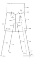
次いで、図5を参照して、遊技盤13における入賞口63,64,65a,640,650aやアウト口71,72などの各構成のレイアウト(配置)について説明する。図5は、遊技盤13の正面模式図である。なお、図5では、入賞口63,64,65a,640,650aなどの各構成が模式的に図示されると共に、遊技盤13の一部が部分的に拡大して図示される。
Next, with reference to FIG. 5, the layout (arrangement) of each configuration of the winning
図5に示すように、内レール61は、遊技領域の正面視において、右下側に配置される部分(第1アウト口71よりも右側の部分)が、直線状に延設されると共に第1アウト口71から離間される方向へ向けて上昇傾斜して形成される。
As shown in FIG. 5, in the front view of the game area, the portion of the
内レール61の右下側の先端部と外レール62の右上側の先端部との間には、それら両レール61,62と共に遊技領域の外縁を画定する樹脂製の外縁部材73が配設される。外縁部材73は、外レール62を延長した円弧状の壁面を内面側に設けて形成される円弧壁部73aと、その円弧壁部73aの下方に連設され鉛直方向(図5上下方向)に沿って直線状に延設される壁面を内面側に設けて形成される垂直壁部73bと、その垂直壁部73bの下方に連設され内レール61へ向けて下降傾斜しつつ直線状に延設される壁面を内面側に設けて形成される傾斜壁部73cとからなる。
A resin
このように、内レール61、外レール62及び外縁部材73により画定される遊技領域は、略円形状の一部(図5下方右側部分)が、略矩形状に形成され外方へ拡大された形状とされる。詳細には、第1アウト口71よりも右側に配設される内レール61の直線状の部分と、外縁部材73の傾斜壁部73c及び垂直壁部73bとにより画定される領域が略矩形状に形成される。
As described above, in the game area defined by the
これにより、遊技領域が内レール61及び外レール62を延長した略円形状に形成される場合と比較して、略矩形状の領域(図5下方右側部分)を備える分、遊技領域全体としての面積を拡大することができる。よって、その拡大した領域を、一般入賞口63、第1入賞口64、第2入賞口640、第1可変入賞装置65、第2可変入賞装置650、スルーゲート67などを配設するスペースとして、或いは、球を流下させる経路を形成するためのスペースとして活用して、各入賞口63,64,65a,640,650aや球の流下経路などの配置の自由度を高めることができる。その結果、第3図柄表示装置81の下縁の位置を下方(図5下側)へ下げることができるので、その分、第3図柄表示装置81の大型化を図ることができる。
As a result, as compared with the case where the game area is formed in a substantially circular shape by extending the
即ち、従来のパチンコ機では、第3図柄表示装置81の下方において、第1入賞口64、第2入賞口640及び可変入賞装置65が上下方向(図5上下方向)に沿って直列に配置されていた。そのため、第3図柄表示装置81の下方に必要なスペースが上下方向に嵩み、かかる第3図柄表示装置81の大型化が阻害されていた。
That is, in the conventional pachinko machine, the first winning
これに対し、本実施形態の遊技盤13によれば、遊技領域の拡大された部分(略矩形状の領域、図5下方右側部分)を入賞口などの配設スペースあるいは球の流下経路の形成スペースとして利用することができる。具体的には、本実施形態では、第2入賞口640および第1可変入賞装置65が第1入賞口64の直下ではなく、上述した遊技領域の拡大された部分に配置される。よって、その分、第1入賞口64の位置を下方へ下げることができるので、第3図柄表示装置81の大型化を図ることができる。
On the other hand, according to the
また、本実施形態の遊技機13によれば、第2特定入賞口650aも、第1入賞口64の直下ではなく、第1入賞口64に対して遊技領域の幅方向一側(可変入賞装置65と反対側、図5左側)にオフセットされ、かつ、内レール61(遊技領域の下縁)に当接する位置(即ち、第2特定入賞口650aと内レール61との間を球が通過不能となる位置)に配置される。よって、その分、第1入賞口64の位置を下方へ下げることができるので、第3図柄表示装置81の大型化を図ることができる。
Further, according to the
この場合、本実施形態の遊技盤13によれば、遊技領域から球排出路へ球を排出するための経路を2ヶ所(第1アウト口71及び第2アウト口72)に設けることで、第3図柄表示装置81の更なる大型化が可能とされている。
In this case, according to the
即ち、第3図柄表示装置81を大型化するためには、かかる第3図柄表示装置81の下縁の位置が下方に下がるため、その分、入賞口の位置も下方へ下げる必要がある。例えば、第1入賞口64の位置が下方へ下がると、案内板部材74(右打ち時の球(可変表示装置ユニット80の右方を通過した球)を第2特定入賞口650aへ案内する部材)の位置も、球を流下させるスペースを第1入賞口64との間に確保するべく、下方へ下げる必要が生じ、その結果、第2特定入賞口650aの位置も下方へ下げる必要が生じる。
That is, in order to increase the size of the third
しかしながら、第2特定入賞口650aの位置が下方へ下がり過ぎると、第2特定入賞口650aの下方(内レール61との間)に球を流下させるためのスペースを確保できなくなる。即ち、入賞口に入賞されずに流下した球を第1入賞口64の下方に配設されるアウト口から排出できなくなる。そのため、かかる第2特定入賞口650aの位置を下方へ下げるには限界があり、第3図柄表示装置81を十分に大型化することができない要因となる。
However, if the position of the second specific winning
これに対し、本実施形態の遊技盤13によれば、上述したように、第1アウト口71に加え、第2アウト口72が、第2特定入賞口650aを挟んで、第1アウト口71の反対側に配設されている(即ち、第2特定入賞口650aの右側および左側に第1アウト口71及び第2アウト口72がそれぞれ配設されている)ので、遊技領域を流下する球であって、第2特定入賞口650aよりも正面視右側(図5右側)において遊技領域の下端(内レール61又は外縁部材73)に達した球は、内レール61又は外縁部材73の傾斜に沿って流下させ、第1アウト口71により球排出路へ排出できる一方、第2特定入賞口650aよりも正面視左側において遊技領域の下端(内レール61)に達した球は、内レール61の傾斜(湾曲)に沿って流下させ、第2アウト口72から球排出路へ排出できる。
On the other hand, according to the
このように、遊技領域から球排出路へ球を排出するための経路を2ヶ所(第1アウト口71及び第2アウト口72)に設けることで、第2特定入賞口650aの下方(内レール61との間)に、球を流下させるためのスペースを確保することを不要とできる。よって、第2特定入賞口650aの位置を更に下方に下げる(内レール61に近接させる又は連設させる)ことができるので、その分、案内板部材75の位置を下方へ下げることができ、ひいては、第1入賞口64の位置を下方へ下げることができるので、その分、第3図柄表示装置81の更なる大型化を図ることができる。
In this way, by providing two routes (first out
なお、本実施形態では、第2入賞口640および第1特定入賞口65aが盤面右側にオフセットされて配設されると共に、第2特定入賞口650aが盤面左側にオフセットされかつ内レール61に近接(又は当接)されて配設されることで、回転動作ユニット300による演出をより効果的に行うことができる。
In the present embodiment, the second winning
即ち、遊技者が右打ちを行う場合には、球が流下する盤面右側のみが遊技者により注目され、特に、第2入賞口640への入賞がなされなかった球に対しては、それ以降の流下が遊技者に注目されることは少ない。この場合、本実施形態では、可変表示装置ユニット80の右方を通過した球のうち、第2入賞口640の上側を右から左へ通過した球は、案内板部材74の上側を通過し、第2特定入賞口650aへ向けて流下される。そのため、第2入賞口640への入賞がなされなかった場合でも、次いで、第2特定入賞口650aへの入賞の機会が発生し、その第2特定入賞口650aへの入賞の期待から、第2入賞口640の上側を右から左へ通過した球を遊技者に注目させる(視線を向けさせる)ことができる。これにより、遊技者の視線を、可変表示装置ユニット80下方における盤面中央にも向けさせることができる。後述するように、本実施形態では、第1入賞口64の背面側に回転動作ユニット300が配設され、その回転動作ユニット300が遊技盤13越しに(遊技盤13を透過して)視認可能とされるので、第2入賞口640への入賞がなされなかった球が、第2特定入賞口650aへ向けて流下する際に、回転動作ユニット300による演出も遊技者に視認させ、かかる回転動作ユニット300の演出効果を高めることができる。
That is, when the player strikes right, only the right side of the board on which the ball flows down is noticed by the player, and in particular, for the ball that has not won the second winning
上述したように、遊技盤13は、ベース板60が光透過性の樹脂材料から形成され、そのベース板60の背面側に配設される回転動作ユニット300を正面側から遊技者に視認させることが可能とされる。ここで、回転動作ユニット300は、第1入賞口64への入賞を契機として又は入賞による抽選の結果を契機として動作される装置であり、遊技盤13(ベース板60)の背面側において、第1入賞口64に対応する位置に配設される。
As described above, in the
よって、第1入賞口64へ向けて流下する球を目で追う遊技者に対し、特に、第1入賞口64に球が入賞した場合には、その第1入賞口64の背後において、回転動作ユニット300による演出を視認させることができるので、第1入賞口64への球の入賞に伴う演出を効果的に行うことができる。なお、回転動作ユニット300の詳細構成については後述する。
Therefore, for a player who visually follows a ball flowing down toward the first winning
この場合、第1入賞口64に対し、第2入賞口640及び第1可変入賞装置65が左右方向(遊技領域の幅方向、図5右方向)にオフセットされて配置されているので、その分、第1入賞口64及び回転動作ユニット300の位置を下方(図5下側)へ下げることができ、その結果、回転動作ユニット300を第1入賞口64に対応する位置であって遊技盤13(ベース板60)の背面側に配設する場合であっても、第3図柄表示装置81の大型化を図ることができる。
In this case, the second winning
即ち、従来のパチンコ機のように、第1入賞口64、第2入賞口640及び第1可変入賞装置65が上下方向に直列に配置される場合には、第1入賞口64に対応する位置において遊技盤13(ベース板60)の背面側に回転動作ユニット300を配設することは、かかる回転動作ユニット300と第2入賞口640及び第1可変入賞装置65とが干渉するため、第1入賞口64、第2入賞口640及び第1可変入賞装置65の配設に必要なスペースが上下方向に嵩み、第3図柄表示装置81の大型化を阻害することになる。
That is, when the first winning
これに対し、本実施形態の遊技盤13によれば、上述したように、第1入賞口64に対し、第2入賞口640、第1可変入賞装置65及び第2可変入賞装置650が左右方向(遊技領域の幅方向)にオフセットして配置されているので、これら第2入賞口640、第1可変入賞装置65及び第2可変入賞装置650と回転動作ユニット300との干渉を回避でき、その分、第1入賞口64の位置を下方へ下げることができ、第3図柄表示装置81の大型化を図ることができる。
On the other hand, according to the
特に、第1可変入賞装置65については、遊技領域の下方右側の略矩形状に拡大された領域を利用して右側にオフセットされることで、そのオフセット量を十分に確保できると共に、第2可変入賞装置650については、第1アウト口71に加えて第2アウト口72が設けられることで、球が流下するための下方のスペースの確保を考慮せずに、その位置を下方へ下げることができる。これにより、回転動作ユニット300を配設するためのスペースをより広く確保できるので、第3図柄表示装置81の大型化と回転動作ユニット300の大型化という背反する課題を解決することができる。その結果、第3図柄表示装置81による演出効果と回転動作ユニット300による演出効果との両者の演出効果を高めることができる。
In particular, with respect to the first variable winning
ここで、回転動作ユニット300は、第1入賞口64を中心として回転可能な略円形状に形成される。これにより、第1入賞口64を取り囲む周囲全体を演出のための領域とすることができる。即ち、回転動作ユニット300による演出をその第1入賞口64の背面側において遊技者に視認させることできる。よって、第1入賞口64への入賞を契機として演出が開始される場合には、球が入球した第1入賞口64を中心とする領域で演出が行われることにより、第1入賞口64への入賞に伴う演出の演出効果を高めることができる。
Here, the
また、回転動作ユニット300の状態(例えば、回転位置や点灯状態)が所定の状態となったことを契機として、第1入賞口64へ球を入賞させることを遊技者が開始する場合には、遊技者が視認している対象物(所定の状態となった回転動作ユニット300)の中心へ向けて遊技球を入球させることとでき、回転動作ユニット300による演出の演出効果を高めることができる。
Further, when the player starts to win a ball in the first winning
更に、このように、回転動作ユニット300が略円形状に形成されることで、かかる回転動作ユニット300の周囲のスペースを有効に活用でき、他の入賞口などのための配設スペースを効率的に確保できる。特に、第2可変入賞装置650の配設スペースを効率的に確保できる。即ち、第1可変入賞装置65については、遊技領域の下方右側の略矩形状に拡大された領域を利用して第1入賞口64に対して右側にオフセットできるため、その右側へのオフセット量を比較的確保しやすい一方、第2可変入賞装置650については、内レール61が円弧状に湾曲されているが故に、第1入賞口64に対する左側へのオフセット量を十分に確保することが困難となる。この場合、回転動作ユニット300が略円形状とされていることで、かかる回転動作ユニット300の下方左側において、第2可変入賞装置650を配設するためのスペースを内レール61との間に効率的に確保できる。
Further, by forming the
また、回転動作ユニット300は、第1入賞口64を中心とする略円形状に形成されるので、かかる回転動作ユニット300を遊技領域の幅方向(図5左右方向)略中央に配置することができる。即ち、第3図柄表示装置81の下縁と内レール61との間の距離(図5上下方向の距離)が最大となる仮想線上に、回転動作ユニット300の中心を配置することができる。よって、第3図柄表示装置81の大型化を図りつつ、遊技領域の限られたスペースを有効に活用できるので、回転動作ユニット300を配設するためのスペースをより広く確保して、かかる回転動作ユニット300の大型化も効率的に行うことができる。
Further, since the
本実施形態では、上述したように、第2入賞口640が、第1入賞口64の直下ではなく、第1入賞口64に対して遊技領域の幅方向他側(第1可変入賞装置65側、図5右側)にオフセットされて配置される。この場合、第2入賞口640は、その開口641が遊技領域の幅方向他側(第1可変入賞装置65側、図5右側)を臨む姿勢で配設される。これにより、第2入賞口640への入賞のために球を流下させるスペースを、かかる第2入賞口640の上方に設けることを不要として、その分、第3図柄表示装置81の下縁の位置を下方に下げることができる。その結果、第3図柄表示装置81の大型化を図ることができる。
In the present embodiment, as described above, the second winning
また、本実施形態では、上述したように、第2特定入賞口650aが、第1入賞口64の直下ではなく、第1入賞口64に対して遊技領域の幅方向一側(第1可変入賞装置65と反対側、図5左側)にオフセットされて配置される。この場合、第2特定入賞口650aは、その開口651が遊技領域の幅方向他側(第1可変入賞装置65側、図5右側)を臨む姿勢で配設される。これにより、第2特定入賞口650aへの入賞のために球を流下させるスペースを、かかる第2特定入賞口650aの上方に設けることを不要として、その分、第3図柄表示装置81の下縁の位置を下方に下げることができる。その結果、第3図柄表示装置81の大型化を図ることができる。
Further, in the present embodiment, as described above, the second specific winning
即ち、第2入賞口640の開口641及び第2特定入賞口650aの開口651が遊技領域の上方(図5上側)の臨む姿勢で配設される場合には、球を流下させるためのスペースを開口641,651の真上に確保する必要が生じ、その分、第3図柄表示装置81の下縁の位置を上方に上げる必要が生じ、第3図柄表示装置81の大型化が阻害される。これに対し、本実施形態のように、開口641,651が遊技領域の幅方向他側を臨む場合には、球を流下させるためのスペースを開口641,651の斜め上方(図5右上側)に確保すれば良く、その分、第3図柄表示装置81の下縁の位置を下方に下げることができる。その結果、第3図柄表示装置81の大型化を図ることができる。
That is, when the
このように、開口641,651が遊技領域の幅方向他側を臨む場合には、電動役物640a,650bを、第2入賞口640及び第2特定入賞口650aの真上ではなく、第2入賞口640及び第2特定入賞口650aの側方に配置することができる。即ち、電動役物640a,650bの配置スペースを第2入賞口640及び第2特定入賞口650aの真上に確保する必要がなく、その分、第3図柄表示装置81の下縁の位置を下方に下げることができる。その結果、第3図柄表示装置81の更なる大型化を図ることができる。
In this way, when the openings 641,651 face the other side in the width direction of the game area, the
更に、開口641,651が遊技領域の幅方向他側を臨むことで、その開口641,651の開放および閉鎖を行うための電動役物640a,650bを一対設けることを不要として、片側のみとすることができる。これにより、電動役物640a,650bを駆動するための駆動手段(例えば、ソレノイド)に必要とされる容量を小型化して、部品コストの削減を図ることができる。同時に、消費エネルギーの抑制を図ることができる。
Further, since the openings 641,651 face the other side in the width direction of the game area, it is not necessary to provide a pair of
また、開口641が遊技領域の幅方向他側を臨むことで、第2入賞口640への入賞の難易度が過度に低下することを防ぐことができる。即ち、本実施形態では、第3図柄表示装置81の下縁の位置を下方に下げるので、入賞口等の配設スペースが限定され、第2入賞口640と、スルーゲート67との配置位置の間隔が狭くなる。そのため、第1入賞口64、第2入賞口640及び第1可変入賞装置65が上下方向に直列に配置される従来のパチンコ機に比較して、第2入賞口640へ入球させる難易度が低下し、遊技性を損なう恐れがある。そこで、開口641を遊技領域の幅方向他側を臨むように形成することで、第2入賞口640の真上から球が入賞することを防止すると共に、電動役物640aが開状態にある場合にのみ第2入賞口640に入賞可能とさせることができる。これにより、第2入賞口640へ入賞させる難易度が低下することを防ぎ、遊技性を向上させることができる。
Further, since the
また、開口651が遊技領域の幅方向他側を臨むことで、第2特定入賞口650aの開口651から、第2特定入賞口650aまでの距離(図5左右方向寸法)を長くしても、第3図柄表示装置81と第2特定入賞口650aとの間の距離に影響を与えない。よって、第3図柄表示装置81の大型化を図りつつ、第2特定入賞口650aへの球の入賞を検出するセンサ装置652を開口651と第2特定入賞口650aとの間に配設することができる。これにより、第2特定入賞口650aへ球が入賞したことの検出速度を速めることができるので、入賞に伴う遊技者の高揚感を高めることができる。
Further, even if the distance (dimension in the left-right direction in FIG. 5) from the
これに加えて、第2特定入賞口650aへのオーバー入賞を防止することができる。即ち、開放されている第2特定入賞口650aに所定個数(例えば10個)の球が入賞したことを契機として、第2特定入賞口650aが閉鎖されるように構成する場合、10個目の球が入賞すると即座に駆動役物650bが閉鎖されることが望ましい。しかし、センサ装置652がベース板60の後方に配設される場合、開口651からセンサ装置652までの距離が離れる。
In addition to this, it is possible to prevent over-winning in the second specific winning
そのため、10個目の球が開口651を通過してからセンサ装置652に到達するまでの期間、即ち駆動役物650bが開状態である期間が長くなり、11球目以降の球が開口651から第2特定入賞口650aに入賞可能な状態が長期間にわたって形成され、遊技の公平性を欠く恐れがある。
Therefore, the period from when the tenth ball passes through the
これに対し、本実施形態の遊技盤13によれば、上述したように、第2特定入賞口650aへの球の入賞を検出するセンサ装置652が開口651と第2特定入賞口650aとの間に配設されているので、開口651を通過した球がセンサ装置652に検出されるまでの期間を短くできる。これにより、11球目以降の球が開口651から入賞可能な状態を生じにくくし、オーバー入賞を防止することができる。
On the other hand, according to the
ここで、本実施形態の遊技盤13において、第1特定入賞口65aと、第2特定入賞口650aとは、それぞれ遊技盤13の左右(他側と一側)方向にオフセットして配置されていることで、遊技者に左右の打ち分けをさせ、遊技性の向上に寄与する。
Here, in the
即ち、本実施形態の遊技盤13においては、第1特定入賞口65aへは可変表示装置ユニット80の右方を通過する方が入賞しやすい一方で、第2特定入賞口650aへは可変表示装置ユニット80の左方を通過した方が入賞しやすい配置となっている。どちらの特定入賞口が開放するかは、その時の大当たりの停止図柄によって決定され、遊技者は、開放される側の特定入賞口を狙うために、左右に打ち分けることになる。
That is, in the
どちらの特定入賞口が開放されるかは、大当たりの停止図柄ごとの回数(ラウンド)単位で設定可能であるので、第1特定入賞口65aもしくは第2特定入賞口650aのみが毎回開放する場合がある一方で、第1特定入賞口65aと第2特定入賞口650aとが回数(ラウンド)ごとに交互に開放する場合もある。
Which specific winning opening is opened can be set in units of the number of times (rounds) for each stop symbol of the jackpot, so only the first specific winning
そのため、遊技者はどちらの特定入賞口が開放するかを回数(ラウンド)単位で確認し、その開放される特定入賞口を狙うために左右に打ち分ける必要があるので、遊技者に遊技盤13の他側のみでなく、一側にも注目させる効果がある。即ち、遊技者が遊技盤13の一側もしくは他側のみに注目するという状況が生じることを防止し、第1入賞口64の後方に配置される回転動作ユニット300が視界に入る状況を作り出すことで、回転動作ユニット300に注目させることができると共に、その演出効果を向上させることができる。
Therefore, it is necessary for the player to confirm which specific winning opening is open in units of the number of times (rounds), and to aim at the opening specific winning opening, it is necessary to strike the left and right sides. It has the effect of drawing attention not only to the other side but also to one side. That is, to prevent a situation in which the player pays attention only to one side or the other side of the
また、左右の打ち分けをする判断を、大当たりの回数(ラウンド)ごとにさせることで、遊技者を退屈させることを防止できると共に、遊技者に左右の打ち分けを行わせることで、同じ姿勢で遊技することにより生じる疲労感を緩和することができる。 In addition, it is possible to prevent the player from getting bored by making a decision to make a left / right strike for each number of jackpots (rounds), and by having the player make a left / right strike, the player can keep the same posture. It is possible to alleviate the feeling of fatigue caused by playing a game.
次いで、図6から図13を参照して、動作ユニット200について説明する。まず、図6から図9を参照して、背面ケース210への各ユニット300〜800の収容構造について説明する。
Next, the
図6は、動作ユニット200の正面斜視図であり、図7から図9は、分解した動作ユニット200を正面視した動作ユニット200の分解正面斜視図である。なお、図8では、揺動動作ユニット800、円環動作ユニット700及び第1結合動作ユニット500が背面ケース210に装着された状態が図示され、図9では、図8に示す装着状態に加えて更に第2結合動作ユニット600及び複合動作ユニット400が背面ケース210に装着された状態が図示される。
FIG. 6 is a front perspective view of the
図6から図9に示すように、動作ユニット200は、底壁部211と、その底壁部211の外縁から立設される外壁部212とから一面側(図7紙面手前側)が開放された箱状に形成される背面ケース210を備える。背面ケース210は、その底壁部211の中央に矩形状の開口211aが開口形成されることで、正面視矩形の枠状に形成される。開口211aは、第3図柄表示装置81(図2参照)の外形に対応した(即ち、第3図柄表示装置81を配設可能な)大きさに形成される。
As shown in FIGS. 6 to 9, one side (front side of the paper in FIG. 7) of the
動作ユニット200は、背面ケース210の内部空間に、回転動作ユニット300、複合動作ユニット400、第1結合動作ユニット500、第2結合動作ユニット600、円環動作ユニット700及び揺動動作ユニット800がそれぞれ収容され、これを1ユニットとして構成される。
In the
具体的には、第1結合動作ユニット500は開口211aの上方となる位置において、円環動作ユニット700は開口211aの下方となる位置において、揺動動作ユニット800は開口211aの左右となる位置において、それぞれ背面ケース210の底壁部211に配設される(図8参照)。
Specifically, the first
この図8に示す状態に対し、第2結合動作ユニット600は円環動作ユニット700の前面側に、複合動作ユニット500は揺動動作ユニット800の前面側に、それぞれ重ね合わされた積層状態で配設され、背面ケース210に収容される(図9参照)。この図9に示す状態に対し、回転動作ユニット300が第2結合動作ユニット600の前面側に重ね合わされた積層状態で配設され、背面ケース210に収容される(図6参照)。
In contrast to the state shown in FIG. 8, the second
このように、本実施形態では、所定の動作ユニット(例えば、第2結合動作ユニット600)に対し、他の動作ユニット(例えば、回転動作ユニット300)が前面側に重ね合わされた積層状態で配設されるので、正面視において、所定の動作ユニットの少なくとも一部(例えば、第2結合動作ユニット600の表ケース体612、図42参照)を、他の動作ユニットによって遮蔽することができる。
As described above, in the present embodiment, the other operating units (for example, the rotary operating unit 300) are arranged in a laminated state in which the other operating units (for example, the rotating operating unit 300) are superposed on the front side with respect to the predetermined operating unit (for example, the second coupling operating unit 600). Therefore, in front view, at least a part of a predetermined operation unit (for example,
言い換えれば、遊技盤13が光透過性材料から形成され、その遊技盤13の背面側に配設される動作ユニットを遊技者が視認可能とされる場合に、所定の動作ユニットの必要な部分のみを遊技者に視認させ、他の部分を他の動作ユニットにより遊技者から遮蔽することができる。これにより、他の動作ユニットによって遮蔽される所定の演出部材については、その全体が遊技者から視認されることを前提として設計する必要がないので、その設計の自由度の向上を図ることができる。
In other words, when the
次いで、図10から図13を参照して、各ユニット300〜800の動作態様の概略について説明する。なお、図10から図13の説明においては、図6から図9を適宜参照する。
Next, the outline of the operation mode of each
図10から図13は、動作ユニット200の正面図である。なお、図10では円環動作ユニット700の円環形成部材790が結合位置に配置された状態が、図11では揺動動作ユニット800のアーム部材820が張出位置に配置された状態が、図12では第1結合動作ユニット500の第1係合部材539及び第2結合動作ユニット600の第2結合部材630が結合位置に配置された状態が、図13では複合動作ユニット400の動作部材491,492が張出位置に配置された状態が、それぞれ図示される。
10 to 13 are front views of the
円環動作ユニット700は、一対の円環形成部材790を備え、これら一対の円環形成部材790を、図8に示す退避位置と図10に示す結合位置との間で動作(変位)させる。図8に示す退避位置では、一対の円環形成部材790は、左右に振り分けられつつ、回転動作ユニット300の背面側に退避され、遊技者から視認不能とされる(図6参照)。一方、図10に示す結合位置では、一対の円環形成部材790は、背面ケース210の開口211a中央(即ち、第3図柄表示装置81の正面)に配置されると共に、互いに結合される(一対の円環形成部材790により円環形状が形成される)。
The
揺動動作ユニット800は、揺動(回転)可能に形成される一対のアーム部材820を備え、これら一対のアーム部材820を、図8に示す退避位置と図11に示す張出位置との間で動作(変位)させる。図8に示す退避位置では、一対のアーム部材820は、複合動作ユニット400の背面側に退避され、遊技者から視認不能とされる(図6参照)。一方、図11に示す張出位置では、一対のアーム部材820は、背面ケース210の開口211a内(即ち、第3図柄表示装置81の正面)にその先端を張り出させる。
The
第1結合動作ユニット500及び第2結合動作ユニット600は、第1係合部材539及び一対の第2結合部材630をそれぞれ備え、これら第1係合部材539及び一対の第2結合部材630を図9に示す退避位置と図12に示す結合位置との間で動作(変位)させる。図9に示す退避位置では、第1係合部材539は複合動作ユニット400の背面側に退避されると共に、第2結合部材630は複合動作ユニット400の背面側に退避され、それぞれ遊技者から視認不能とされる(図6参照)。一方、図12に示す結合位置では、第1係合部材539及び一対の第2結合部材630が背面ケース210の開口211a中央(即ち、第3図柄表示装置81の正面)に配置されると共に、互いに結合される。
The first
複合動作ユニット400は、揺動(回転)可能に形成される4本の部材(動作部材491,492)を備え、これら4本の部材(動作部材491,492)を、図9に示す退避位置と図13に示す張出位置との間で動作(変位)させる。図9に示す退避位置では、4本の部材(動作部材491,492)は、背面ケース210の開口211a(即ち、第3図柄表示装置81)の側方に退避され、2本一組がそれぞれ上下方向に沿って直線状に整列した姿勢に配置される。一方、図13に示す張出位置では、4本の部材(動作部材491,492)は、背面ケース210の開口211a内(即ち、第3図柄表示装置81の正面)にその先端を張り出させ、開口211aの中央からそれぞれ放射直線状に延びる姿勢に配置される。
The
回転動作ユニット300は、回転可能に形成される回転部材330を備え、その回転部材330を回転動作させる。なお、図10から図13に示すように、回転動作ユニット300の回転部材330は、定位置において回転動作され、また、複合動作ユニット400の動作部材491,492は、張出位置または退避位置のいずれの位置においても最前面に配置されるため、遊技盤13(図2参照)を介して、常に遊技者から視認可能とされる。
The
これら各動作ユニット300〜800は、それぞれ独立して動作可能に形成されると共に、上述したように、重ね合わされた(積層された)状態で配設されるので、各動作ユニット300〜800のうちの層を違えて配設されるものについては、同時に動作させることができる。即ち、図10から図13で例示したように、各動作ユニット300〜800をそれぞれ単体で動作させるだけでなく、これらの動作を組み合わせることができるので、その演出効果を高めることができる。
Each of these
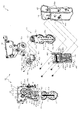
図14から図19を参照して、回転動作ユニット300について説明する。図14は、回転動作ユニット300の正面斜視図であり、図15は、回転動作ユニット300の背面図である。
The
回転動作ユニット300は、上述したように、遊技盤13(ベース板60)の背面側において、第1入賞口64(図2又は図5参照)に対応する位置(正面視において重なる位置)に配設される演出部材であり、正面中央に受入口361が開口され、第1入賞口64に入賞された球を、受入口361から受け入れ、案内通路380を介して、図示しない球排出路へ案内する。
As described above, the
回転動作ユニット300の正面側には、正面視円環状の回転部材330と、装飾用の樹脂製部材である装飾部材370とが配設され、回転部材330の略中心部分には、受入口361(固定部材360)が配置される。回転部材330は、光透過性の樹脂材料から回転可能に形成され、その背面側に配設されたLEDの点灯や点滅を前面側へ透過させると共に、自身が回転されることで、第1入賞口64(図2又は図5参照)の周囲において、所定の演出を行う。
A rotating
図16及び図17は、分解した回転動作ユニット300を正面視した回転動作ユニット300の分解正面斜視図である。なお、図16では、回転部材330のみを分解した状態が図示される。また、図17では、装飾部材370の図示が省略されると共に、第1歯車351と第3歯車353との一部が部分的に断面視される。
16 and 17 are an exploded front perspective view of the
図16及び図17に示すように、回転動作ユニット300は、その最背面側において骨格をなすケース体310と、そのケース体310に固着される電飾基部320と、その電飾基部320の正面側に配設される回転部材330と、その回転部材330に駆動モータ340の回転駆動力を伝達するための複数の歯車(第1歯車351、第2歯車352及び第3歯車353)と、それら複数の歯車のうちの第1歯車351をケース体310に固定するための固定部材360と、ケース体310の周囲に配設される装飾部材370と、を主に備えて構成される。
As shown in FIGS. 16 and 17, the
ケース体310は、電飾基部320に対応する正面視略円環状に形成される電飾基部取り付け部311と、その電飾基部取り付け部311よりも背面側に後退して形成される歯車取り付け部312と、それら電飾基部取り付け部311及びは歯車取り付け部312の外縁からそれぞれ外方へ延設される取り付け台座313とを主に備え、これらが樹脂材料から一体に形成される。
The
電飾基部取り付け部311には、正面側に電飾基部320が、外周側に装飾部材370が、それぞれ締結ねじにより締結固定される。歯車取り付け部312は、第1歯車351から第3歯車353の外形にそれぞれ対応して凹設される正面視略円形状の3つの凹部が互いに連なって形成され、これら各凹部に第1歯車351から第3歯車353がそれぞれ収納(配設)される。
An
電飾基部取り付け部311の内周側には、歯車取り付け部312のうちの第1歯車351が収納される部位の上方に、開口311aが開口形成される。ケース体310に開口311aが形成されることで、かかる開口311aを介して、ケース体310の背面側から締結ねじにより第1歯車351(締結座部351d)に回転部材330(被締結部333)を締結固定することができる。よって、回転部材330の正面側に締結ねじが露出することを回避して、その外観の向上を図ることができる。
An
歯車取り付け部312には、第1歯車351が収納される凹部に、通過口314と、被締結部315と、挿通部316と、ガイド凸部317とがそれぞれ形成される。通過口314は、固定部材360の受入口361に連通される通路であり、固定部材360の受入口361から流入した球を、ケース体310の背面側に形成される案内通路380へ案内する。
The
なお、案内通路380は、ケース体310の背面に断面コ字状の部材が装着されることで、その装着された部材とケース体310の背面との間に球が通過可能な通路として形成される(図15参照)。案内通路380は、ケース体310の背面において通過口314に連通されると共に、下方へ向けて延設される。
The
取り付け台座313には、挿通孔が穿設されており、その挿通孔に挿通された締結ねじを第2結合動作ユニット600の表ケース体612に締結することで、回転動作ユニット300が第2結合動作ユニット600を介して背面ケース210に締結固定される(図9及び図42参照)。
An insertion hole is formed in the mounting
被締結部315は、固定部材360を歯車取り付け部312に締結固定するための締結ねじが締結される部位(内周にめねじが刻設された凹部)であり、通過口314を挟んで左右非対称となる位置に一対が形成される(図18参照)。挿通部315は、歯車取り付け部312(ケース体310)を背面側の第2結合動作ユニット600の表ケース体612(図9及び図42参照)に締結固定するための締結ねじを挿通させるための貫通孔であり、通過口314の上方に形成される。
The fastened
ガイド凸部317は、第1歯車351の回転をガイド(案内)するためのレール状の部位であり、正面視円環状の凸部として歯車取り付け部312の正面から突設される。第1歯車351の背面には、ガイド部317に対応する正面視円環状のガイド凹部351eが凹設されており(図19参照)、そのガイド凹部351eにガイド突部317が嵌め入れられることで、歯車取り付け部312に対する第1歯車351の回転位置が規定される。
The guide
ここで、歯車取り付け部312は、ガイド凸部317に取り囲まれて形成される正面視円形状の領域において、通過口314が中心から下方にずれた位置(偏心した位置)に配設される一方、被締結部315が通過口314を挟んで左右に配設され、挿通部316が通過口314の上方に配設される。これにより、後述するように、限られたスペースにおいて締結固定のためのスペースを効率的に確保しつつ、ケース体310及び固定部材360の剛性を確保することができる。
Here, the
歯車取り付け部312には、第2歯車352が収納される凹部に、軸部318が突設される。軸部318は、第2歯車352を軸支するための軸体であり、第2歯車352の中心に穿設された軸孔352aに挿通される。なお、本実施形態では、第2歯車352の軸孔352aに挿通された軸部318の先端に、第2歯車352の抜け止めを設けることを省略可能に形成される。詳細については後述する。
In the
歯車取り付け部312の背面には、第3歯車353が収納される凹部に対応する位置に、駆動モータ340が配設される。駆動モータ340は、その駆動軸340aを歯車取り付け部312の正面(第3歯車353が収納される凹部内)に突出させた状態で配設され、その駆動軸340aに第3歯車353が固着される。
A
電飾基部320は、正面視円環状に形成されると共に正面側に複数のLED321aが実装される基板部321と、その基板部321の正面に配設されると共に基板部321の正面を複数の領域に区画する区画部322とを備えて構成される。
The
詳細には、区画部322は、基板部321の内縁および外縁に沿って延設される正面視環状の内縁リブ322a及び外縁リブ322bと、それら両リブ322a,322bの間に所定間隔を隔てつつ同心に形成される正面視環状の中間リブ322cと、これら各リブ322a〜322cの中心から径方向外方へ向けて放射直線状に延設される複数の放射リブ322dとが格子状に交差して配設される。なお、複数の放射リブ322dは、周方向等間隔(本実施形態では略30度間隔)に配設される。
Specifically, the
よって、本実施形態では、電飾基部320には、内周側に12個および外周側に12個の合計24個の領域が区画部322により区画され、それら区画された各領域には、それぞれ1乃至2個のLED321aが配設される。これにより、各LED321aをそれぞれ個別に点灯や点滅させる際には、その点灯や点滅に関連する領域と関連しない領域との間で明暗の差を大きくすることができ、その結果、演出効果を高めることができる。
Therefore, in the present embodiment, the
回転部材330は、中心に開口が形成される正面視円環状の回転本体331と、その回転本体331の外縁から軸方向に延設される円筒状の外壁部332とを備え、これらが光透過性の樹脂材料から一体に形成される。回転本体331の中心に形成される開口の内径は、固定部材360の外径に対応されており、組み立て状態では、回転本体331の開口内に固定部材360が収容される(図14参照)。
The rotating
回転本体331の背面には、被締結部333が複数箇所(本実施形態では3箇所)に形成される。被締結部333は、回転本体331(回転部材330)を第1歯車351に締結固定するための締結ねじが締結される部位(内周にめねじが刻設された凹部)であり、回転本体331の中心からそれぞれ同距離となる位置であって、周方向に不等間隔となる位置に配設される。
On the back surface of the rotating
回転本体331の正面には、正面視環状に形成されると共にそれぞれ同心に配置される複数の環状突部331a〜331eと、それら環状突部331a〜331eの中心から径方向外方へ向けて放射直線状に延設される複数の放射突部331fとが突設される。なお、複数の放射突部331fは、周方向等間隔(本実施形態では略30度間隔)に配設される。即ち、本実施形態では、放射突部331fの周方向間隔が、電飾基部320の放射リブ322dの周方向間隔に一致される。
On the front surface of the rotating
回転本体331は、全体に均等の肉厚(厚み寸法)に形成されており、環状突部331a〜331e又は放射突部331fが突設される部分では、その突設される分だけ肉厚(厚み寸法)が厚く(大きく)される。よって、これら各突部331a〜331fが突設される部分において、光を透過しにくくすることができる。
The rotating
この場合、回転動作ユニット300の組み立て状態では、径方向の最外方に位置する環状突部331eに対応する位置(正面視において重なる位置)に区画部材322の外縁リブ322bが、環状突部331dの次に径方向外方に位置する部位であって環状突部331d及び環状突部331cの間に対応する位置(正面視において重なる位置)に区画部材322の中間リブ322cが、それぞれ配置される。
In this case, in the assembled state of the
このように、回転部材330には、電飾基部320の区画部材322により区画された各領域に対応する領域が、各突部331a〜331fにより区画されているので、電飾基部320の各LED321aをそれぞれ個別に点灯や点滅させる際には、その点灯や点滅に関連する領域と関連しない領域との間で明暗の差を大きくすることができ、その結果、演出効果を高めることができる。
As described above, in the rotating
かかる領域の区画は、回転部材330においては、上述したように、環状突部331a〜331e及び放射突部331fを正面から突設させ、厚み寸法を大きくすることにより達成する。これにより、例えば、回転部材330の正面に領域を区画するための印刷を施したりや別部材を配設する必要がなく、回転部材330全体を単一色により形成できるので、製品コストの削減を図ることができるだけでなく、その演出効果を高めることができる。
As described above, in the rotating
回転部材330は、外壁部332の内径寸法が、電飾基部320の区画部材322(外縁リブ322b)の外径寸法と略同一または若干大きな寸法に設定され、組み立て状態では、外壁部332の内周側に電飾基部320の区画部材322が内嵌される構造とされる。これにより、LED321aの光が区画部材322の外周側から漏れることを抑制し、正面側への光の照射を効率良く行わせることができる。また、第1歯車351に回転部材330を締結固定する際には、外壁部332に区画部材322が内嵌される構造とすることで、かかる内嵌状態とすることで、両者を芯合わせさせた状態で相対回転させることができる。即ち、両者を相対回転させるのみで、第1歯車351の各締結座部351d(挿通孔)に対して回転部材330の各被締結部333を位置合わせすることができ、径方向の位置を調整する必要がないので、その分、作業性の向上を図ることができる。
The inner diameter of the
第1歯車351は、中心に開口を有しその開口内に固定部材360が挿通可能とされる正面視円環状の第1本体351aと、その第1本体351aの外周面に刻設される歯351bと、その歯351bよりも第1歯車351の正面側(回転部材330側)となる位置で第1本体351aの外周面からフランジ状に張り出す第1フランジ部351cと、その第3フランジ部351cよりも第1歯車351の正面側(回転部材330側)となる位置で第1本体351aの外周面から張り出す複数(本実施形態では3個)の締結座部351dと、第1本体351aの背面側に凹設され歯車取り付け部312のガイド凸部317が挿通されるガイド凹部351e(図19参照)と、を備え、固定部材360が歯車取り付け部312に締結固定されることで、その固定部材360と歯車取り付け部312との間で回転可能に保持される。
The
第1歯車351は、第1本体351aの外周面から第1フランジ部351cが張り出して形成されるので、かかる第1フランジ部351cにより第1歯車351の剛性を高めることができる。特に、本実施形態では、第1フランジ部351cが歯351bの軸方向端面に連設されるので、歯351bの剛性を高めることができる。その結果、第2歯車352との間の歯合状態を適正として、伝達効率の向上を図ることができると共に歯351b,352bの耐久性の向上を図ることができる。また、第1フランジ部351cは、後述するように、第2歯車352の抜け止めを兼用するので、その分、抜け止め用の部品を省略して、部品コストの削減が図ることができる。
Since the
締結座部351dは、回転本体331(回転部材330)の被締結部333に締結固定される部位であり、回転本体331の各被締結部333に対応する位置にそれぞれ配設される。即ち、各締結座部351dには、被締結部333に締結する締結ねじを挿通させるための挿通孔が穿設されており、その挿通孔は、第1歯車351の中心からそれぞれ同距離となる位置であって、周方向に不等間隔となる位置に配設される。よって、第1歯車351と回転部材330とは、1の位相位置のみで締結固定が可能となるので、第1歯車351に回転部材330を組み付ける際には、その周方向位置を作業者が間違えて組み付けることを回避できる。
The
第1歯車351と回転部材330とを1の位相位置のみで締結固定を可能とするためには、必ずしも第1歯車351の中心からそれぞれ同距離となる位置に各締結座部351の挿通孔が配設されている必要はない。各締結座部351の挿通孔は、周方向に等間隔となる位置であって、回転本体331の中心からの距離がそれぞれ異なる位置に配設されていても良い。
In order to enable fastening and fixing of the
但し、本実施形態のように、第1歯車351の中心からそれぞれ同距離となる位置に各締結座部351の挿通孔を配設することが好ましい。即ち、各締結座部351dの長さ寸法(張り出し長さ)をそれぞれ同一とできるので、第1歯車351を樹脂材料から射出成形する場合には、その成形性の向上を図ることができるからである。
However, as in the present embodiment, it is preferable to dispose the insertion holes of the
ここで、ケース体310の背面側から締結ねじを締結座部351dの挿通孔を介して回転部材330の被締結部333に締結固定するためには、ケース体310に開口311aを開口形成する必要がある。この場合、第1歯車351の中心からそれぞれ異なる距離に各締結部材351の挿通孔が配置される場合には、各挿通孔の移動軌跡が異なることとなり、その分、開口311aの開口幅を大きくする必要があるため、剛性の低下を招くところ、本実施形態によれば、各挿通孔の移動軌跡を同一とできるので、その分、開口311aの開口幅を最小に抑えることができる。
第2歯車352は、正面視円形状の第2本体352aと、その第2本体352aの外周面に刻設される歯352bと、第2本体352aの中心に穿設される軸孔352cとを供え、その軸孔352cに歯車取り付け部312の軸部318が挿通されることで、第1歯車351に歯合された状態で歯車取り付け部312に回転可能に保持される。
Here, in order to fasten and fix the fastening screw from the back side of the
The
第3歯車353は、正面視円形状の第3本体353aと、その第3本体353aの外周面に刻設される歯353bと、その歯353bよりも第3歯車353の正面側(回転部材330側)となる位置で第3本体353aの外周面からフランジ状に張り出す第3フランジ部353cと、とを備え、第3本体353aに駆動モータ370の駆動軸340aが固着されることで、第2歯車352に歯合された状態で駆動モータ340の駆動軸340aに保持される。
The
よって、駆動モータ340が回転駆動され、第3歯車353が回転されると、その回転が第2歯車352に伝達され、第2歯車352が回転されると共に、その第2歯車352の回転が第1歯車351に伝達され、第1歯車351が回転される。その結果、第1歯車351に締結座部351d及び被締結部333を介して締結固定される回転部材330に駆動モータ340の駆動力が伝達され、かかる回転部材330が回転される。
Therefore, when the
なお、第1歯車351の場合と同様に、第3歯車353は、第3本体353aの外周面から第3フランジ部353cが張り出して形成されるので、かかる第3フランジ部353cにより第3歯車353の剛性を高めることができる。特に、本実施形態では、第3フランジ部353cが歯353bの軸方向端面に連設されるので、歯353bの剛性を高めることができる。その結果、第2歯車352との間の歯合状態を適正として、伝達効率の向上を図ることができると共に歯353b,352bの耐久性の向上を図ることができる。また、第3フランジ部353cは、後述するように、第2歯車352の抜け止めを兼用するので、その分、抜け止め用の部品を省略して、部品コストの削減が図ることができる。
As in the case of the
固定部材360は、第1歯車351を歯車取り付け部312に固定するための円柱状の部材であり、受入口361と、挿通部362とを備える。受入口361は、遊技盤13への装着状態において、第1入賞口64に連通される通路であり、第1入賞口64から流入した球を、歯車取り付け部312の通過口314へ案内する。挿通部362は、固定部材360を歯車取り付け部312の被締結部315又は挿通部316に締結または挿通する締結ねじを挿通させるための貫通孔である。
The fixing
図18(a)は、ケース体310の正面図であり、図18(b)は、固定部材360の正面図である。なお、図18(a)では、第1歯車351、第2歯車352及び第3歯車353がケース体310に配設された状態が図示されると共に、第1歯車351及び第3歯車353の一部が部分的に断面視される。
FIG. 18A is a front view of the
図18(a)及び図18(b)に示すように、ケース体310の歯車取り付け部312に形成される通過口314は、上述したように、第1歯車351の中心から下方(図18(a)下側)に位置ずれして(偏心して)配置される。そのため、歯車取り付け部312は、通過口314の周囲に形成される円環状の領域において、通過口314の上方の幅寸法(図18(a)上下方向寸法)が下方の幅寸法に比較して広くされる。
As shown in FIGS. 18A and 18B, the
第1歯車351の内周側に挿通され、歯車取り付け部312に締結固定される固定部材360についても同様に、その固定部材360に形成される受入口361は、固定部材360の中心から下方(図18(b)下側)に位置ずれして(偏心して)配置される。そのため、固定部材360は、受入口361の周囲に形成される円環状の領域において、受入口361の上方の幅寸法(図18(b)上下方向寸法)が下方の幅寸法に比較して広くされる。
Similarly, for the fixing
このように、本実施形態では、通過口314及び受入口361を位置ずれ(偏心)させ、その周囲(円環状の領域)の一部に広い(幅寸法が大きくされた)部分を形成すると共に、その広くされた部分に挿通部316,362をそれぞれ配置(穿設)するので、限られたスペースを有効に活用して、大径の孔を穿設できると共に、かかる場合でも、ケース体310及び固定部材360の剛性を確保することができる。
As described above, in the present embodiment, the
即ち、挿通部316,362は、回転動作ユニット300を第2結合動作ユニット600の表ケース体612(図9又は図42参照)に締結固定するための締結ねじが挿通可能な孔として形成される部位であり、支持する重量が嵩むことから大径の締結ねじが挿通されるため、比較的大径の孔として形成される必要があるところ、上述のように、一部に広い(幅寸法が大きくされた)部分を形成することで、かかる部分を利用して、大径の孔を穿設するスペースを効率的に確保できる。一方で、このような大径の孔を穿設する場合でも、部分的に広くされた領域に孔が穿設されるため、その剛性を確保できる。
That is, the
図19は、第1歯車351、第2歯車352及び第3歯車353のケース体310による支持構造を模式的に図示する模式図であり、図18の矢印XIX方向視に対応する。なお、図19では、ケース体310が断面視されると共に、第1歯車351及び第2歯車352の一部が部分的に断面視される。
FIG. 19 is a schematic view schematically showing a support structure of the
図19に示すように、第1歯車351は、背面側に凹設されたガイド凹部351eに歯車取り付け部312のガイド凸部317が嵌め入れられることで、歯車取り付け部312に回転可能に支持される。また、第1歯車351は、歯車取り付け部312に締結固定される固定部材360によって、歯車取り付け部312から軸方向(図19上側)へ脱落することが規制される。一方、第3歯車353は、駆動モータ340の駆動軸340aに固着される。なお、固着の方法としては、例えば、圧入によるものや接着剤によるものが例示される。
As shown in FIG. 19, the
第2歯車352は、第2本体352aに穿設される軸孔352cに歯車取り付け部312の軸部318が挿通されることで、その歯352bが第1歯車351及び第3歯車353の歯351b,353bに歯合された状態で、歯車取り付け部312に回転可能に軸支される。
The
この場合、上述したように、第1歯車351及び第3歯車353には、それら第1本体351a及び第3本体353aの外周面から径方向外方へ張り出す第1フランジ部351c及び第3フランジ部353cがそれぞれ形成されており、これら第1フランジ部351c及び第3フランジ部353cは、第2歯車352の軸方向端面に重なる位置まで張り出されている。これにより、第2歯車352が、歯車取り付け部312の軸部318から軸方向(図19上側)へ抜け出ることを規制することができる。その結果、抜け止め用の部品を軸部318の先端に配設する必要がないので、その分、部品点数を削減して、部品コストを抑えることができる。また、組み立て時には、第2歯車352については、歯車取り付け部312の軸部318を軸孔352cに挿通させるだけで良く、抜け止めの部品を装着する工程を省略できるので、その分、製造コストを抑えることができる。
In this case, as described above, the
本実施形態では、第1歯車351の第1フランジ部351cと第3歯車353の第3フランジ部353cとが第2歯車352に対して異なる2箇所で当接するので、第2歯車352が軸方向へ抜け出ることを確実に規制できるだけでなく、かかる第2歯車352が軸部318に対して傾斜しながら回転することを抑制できる。その結果、第2歯車352の歯352bと第1歯車351及び第3歯車353の歯351b,353bとの歯合状態を適正として、伝達効率の向上と耐久性の向上とを図ることができる。特に、第2歯車352に当接する2箇所は位相を約180度異ならせる位置に設定されるので、上述した効果をより顕著に発揮できる。なお、2箇所の位相は、約160度から約180度の範囲内に設定されることが好ましい。
In the present embodiment, the
ここで、第1歯車351及び第3歯車353の第1フランジ部351c及び第3フランジ部353cは、歯351b及び歯353bの谷よりも山頂側に張り出されていれば足りる。歯351b及び歯353の谷よりも張り出されていれば、第2歯車352の歯352bの山頂側の端面に当接できるからである。また、第1フランジ部351c及び第3フランジ部353cの形成に要する材料を抑制して、軽量化および材料コストの削減を図ることができるからである。但し、第1フランジ部351c及び第3フランジ部353cは、歯351b及び歯353の山頂側よりも更に径方向外方へ張り出されていることが好ましい。第2歯車352の傾斜をより確実に抑制できるからである。
Here, it is sufficient that the
次いで、図20から図30を参照して、複合動作ユニット400について説明する。
Next, the combined
なお、複合動作ユニット400は、上述したように4本の部材(動作部材491,492)を備え(図7及び図13参照)、それら各部材(動作部材491,492)を動作(変位)させるための4つのユニットからなる。即ち、複合動作ユニット400は、背面ケース210の正面視において、開口211aの左側に上下方向に沿って列設される2つのユニットと、開口211aの右側に上下方向に沿って列設される2つのユニットからなる。この場合、各部材(動作部材491,492)を動作(変位)させるための構造(技術思想)は4つのユニットにおいてそれぞれ同一であるので、以下においては、これら4つのユニットのうちの1のユニット(開口211aの右側上方に配設されるユニット、図7及び図13参照)を複合動作ユニット400と称して説明する。
As described above, the
図20は、複合動作ユニット400の正面斜視図である。図20に示すように、複合動作ユニット400は、取り付けベース410の前面側に動作部材491,492が配設され、この動作部材491,492に開閉動作および回転動作を複合的に行わせる(図27参照)。即ち、動作部材491,492は、互いの長手方向を平行とする姿勢で対向配置されており、その対向間隔を拡大縮小させる動作(開閉動作)と、取り付けベース410に配設される基部側を中心として回転する動作(回転動作)とが実行可能に形成される。なお、取り付けベース410の前面には、装飾体として形成される装飾部材411が配設される。
FIG. 20 is a front perspective view of the combined
本実施形態では、動作部材491,492の2種類の動作態様(開閉動作および回転動作)を1の駆動モータ430により実行が可能となるように形成される。そのため、2種類の動作態様に対して駆動モータ430を個別に設ける必要がなく、その分、製品コストの削減を図ることができる。かかる構造の詳細構成について、図21から図23を参照して説明する。
In the present embodiment, two types of operation modes (opening / closing operation and rotation operation) of the operating
図21は、分解した複合動作ユニット400を正面視した複合動作ユニット400の分解正面斜視図である。また、図22は、複合動作ユニット400の一部を分解した状態における複合動作ユニット400の分解斜視図であり、図22左側に図示される構成が正面視されると共に図22右側に図示される構成が背面視される。なお、図21及び図22では、装飾部材411の図示が省略されると共に、図22では、取り付けベース410の図示が省略される。
FIG. 21 is an exploded front perspective view of the combined
図21及び図22に示すように、複合動作ユニット400は、背面ケース210(図7参照)に配設される取り付けベース410と、その取り付けベース410に取り付けられる保持ケース420と、その保持ケース420に回転可能に軸支される複数の歯車と、それら複数の歯車を回転駆動力するための駆動力を発生する駆動モータ430と、保持ケース420に基端が回転可能に軸支される裏アーム体471及び表アーム体472と、それら裏アーム体471及び表アーム体472の対向面間に狭装されるスライドラック部材481、第1ピニオン脚部材482及び第2ピニオン脚部材483と、それら第1ピニオン脚部材482及び第2ピニオン脚部材483の先端に連結される動作部材491、492とを主に備える。
As shown in FIGS. 21 and 22, the combined
保持ケース420は、取り付けベース410に取り付けられる裏ケース体421と、その裏ケース体421の正面側に対向配置される表ケース体422とを備え、それら裏ケース体421と表ケース体422との対向間に形成される内部空間に複数の歯車が回転可能に軸支されつつ収容される。
The holding
保持ケース420には、裏ケース体421の背面側に駆動モータ430が配設されると共に、裏ケース体421及び表ケース体422の対向間には、3本の回転軸(減速軸425、第1軸426及び第2軸427)がそれぞれ駆動モータ430の駆動軸と平行となる姿勢で架設され、これら減速軸425から第2軸427に複数の歯車が回転可能に軸支される。なお、駆動モータ430の駆動軸には、ピニオンギヤ431が固着される。
In the holding
複数の歯車は、減速軸425に軸支される減速歯車441と、第1軸426に軸支される開閉第1歯車451及び回転第1歯車461と、第2軸427に軸支される開閉第2歯車452及び回転第2歯車462とからなる(図24及び図25参照)。減速歯車441は、大径の歯車441aと、その大径の歯車441aに同軸に一体に形成される小径の歯車441bとを備え、ピニオンギヤ431の回転を減速させつつ開閉第1歯車451へ伝達する。ここで、図23を参照して、開閉第1歯車451、開閉第2歯車452、回転第1歯車461及び回転第2歯車462について説明する。
The plurality of gears are a
図23は、開閉第1歯車451、開閉第2歯車452、回転第1歯車461及び回転第2歯車462の正面斜視図である。開閉第1歯車451は、本体部451aと、その本体部451aに貫通形成され第1軸426が挿通される挿通孔451bと、その挿通孔451bを中心として本体部451aの外周に全周にわたって刻設される歯451cと、本体部451aの軸方向端面(正面)から突出され挿通孔451bを挟んで位置する一対の連結突部451dと、本体部451aに貫通形成され挿通孔451bの側方に位置する位置決め孔451eとを備える。
FIG. 23 is a front perspective view of the opening / closing
回転第1歯車461は、開閉第1歯車451の正面側に配設されその開閉第1歯車451と共に第1軸426(図21及び図22参照)に軸支される歯車であり、本体部461aと、その本体部461aに貫通形成され第1軸426が挿通される挿通孔461bと、その挿通孔461bを中心として本体部461aの外周の一部に刻設される歯461cと、本体部451aに貫通形成され挿通孔461bを挟んで位置する一対の連結孔461dと、本体部451aの外周から径方向外方へ張り出して形成され光センサにより検出される被検出部461eとを備える。
なお、回転第1歯車461の本体部461aは、歯461cの形成領域を除く(即ち、歯461cが非形成とされる)領域の外周面が挿通孔461bの軸を中心とする円筒面(以下「円筒面461a1」と称す)として形成される。円筒面461a1の外径(挿通孔461bの軸からの距離)は、歯461cの歯先円の外径よりも小さく、かつ、歯461cの歯底円の外径よりも大きくされる。これにより、後述するように、回転第1歯車461の本体部461aの剛性の向上と、回転第2歯車462の非形成面462a1形成部分の剛性の向上との両立を図ることができる。
The rotary
The
また、回転第1歯車461の一対の連結孔461dには、開閉第1歯車451の一対の連結突部451dがそれぞれ内嵌可能に形成され、この内嵌により、開閉第1歯車451に対し回転第1歯車461の回転位置(位相)を位置決めすることができると共に両者を連結して同位相で一体的に回転させることができる。
Further, a pair of connecting
開閉第2歯車452は、本体部452aと、その本体部452aに貫通形成され第2軸427が挿通される挿通孔452bと、その挿通孔452bを中心として本体部452aの外周の一部に刻設される歯452cと、本体部452aの軸方向端面(正面)から突出される連結突部452dと、本体部452aに貫通形成され位置決め孔452eとを備える。
The opening / closing
なお、開閉第2歯車452は、裏ケース体421との間に裏アーム体471を挟み込んだ状態で(即ち、裏アーム体471の正面側に)配設され、その裏アーム体471の軸支孔471aに沿って立設される円筒状の部分に挿通孔452bが回転可能に軸支される(図21及び図22参照)。また、開閉第2歯車452の連結突部452dは、スライドラック部材481の連結溝481cに連結され、この連結を介して、開閉第2歯車452の回転がスライドラック部材481に伝達される(図26参照)。
The opening / closing
回転第2歯車462は、本体部462aと、その本体部462aに貫通形成され第2軸427が挿通される挿通孔462bと、その挿通孔462bを中心として本体部462aの外周の一部に刻設される歯462cと、本体部462aの軸方向端面(正面)から突出されると共に内部に孔が貫通形成される一対の連結突部462dと、本体部452aに貫通形成される位置決め孔462eとを備える。
The rotary
なお、回転第2歯車462の本体部462aは、歯462cの両側に連設されると共に歯が非形成とされる領域の外周面(以下「非形成面462a1」と称す)が挿通孔462b側へ向けて凹む(即ち、曲率中心を径方向外方側に有する)湾曲面として形成される。詳細には、非形成面462a1の曲率は、回転第1歯車461の円筒面461a1と同一の曲率または若干小さな曲率(即ち、若干大きな半径)に設定される。
The
また、回転第2歯車462は、開閉第2歯車452の正面側(軸方向に重ねた姿勢)に配設されるが、この開閉第2歯車452とは独立された状態(即ち、異なる位相で相対回転可能な状態)で第2軸427に軸支される。また、回転第2歯車462は、連結突部462dの孔に挿通された締結ねじを表アーム体472の連結突部472e(図22参照)に締結することで、互いの連結突部462d,472eどうしが連結される。よって、かかる連結を介して、回転第2歯車462と表アーム体472(及び裏アーム体471)とを同位相で一体的に回転させることができる。
Further, the rotary
このように、回転第2歯車462には、その連結突部462dに表アーム体472の連結突部472e(図22参照)が締結固定されるので、連結突部462d,472eを介して両者を複数箇所(本実施形態では2箇所)で連結して、回転第2歯車462及び表アーム体472を一体の構造体として形成できる。その結果、表アーム体472の剛性を利用して回転第2歯車462の剛性を高めることができる。
In this way, since the connecting
ここで、後述するように、回転第2歯車462は、その非形成面462a1を回転第1歯車461の円筒面461a1に当接させる際にその回転第1歯車461から反力を受けるため(図28から図30参照)、その反力に抗するための剛性を確保する必要がある。この場合、例えば、回転第2歯車462を厚肉化すれば重量が増加し、高剛性の素材を採用すれば材料コストが嵩む。
Here, as will be described later, the rotary
これに対し、本実施形態の回転第2歯車462によれば、表アーム体472の剛性を利用して(即ち、表アーム体472と一体となることで)、その剛性を高めることができるため、回転第2歯車462の厚肉化や高剛性素材を採用する必要がない。これにより、回転第2歯車462の軽量化および低コスト化を図りつつ、回転第2歯車462の耐久性の向上を図ることができる。
On the other hand, according to the rotary
特に、回転第2歯車462は、その連結突部462dが非形成面462a1の背面側(即ち、組み立て状態において、非形成面462a1を挟んで回転第1歯車461の円筒面461a1と対向する位置、図28から図30参照)に配設されるので、後述するように、回転第2歯車462の非形成面462a1を回転第1歯車461の円筒面461a1に当接させる際にその回転第1歯車461の円筒面461a1から反力を受ける部分の剛性を表ケース体472等の剛性や金属製の締結ねじを利用して効果的に高めることができる。その結果、回転第2歯車462の軽量化および低コスト化とその耐久性の向上との両立をより一層図ることができる。
In particular, the rotary
また、回転第1歯車461及び回転第2歯車462の歯車比(ギヤ比)は、開閉第1歯車451及び開閉第2歯車452の歯車比(ギヤ比)と同一とされる。よって、後述するように、回転第1歯車461が単位回転角度だけ回転される際に回転第2歯車462が回転される回転角度は、その単位回転角度と同じだけ、開閉第1歯車451が回転される際に回転第2歯車462が回転される回転角度と一致される。
Further, the gear ratio (gear ratio) of the rotating
図21及び図22に戻って説明する。組み立て状態では、駆動モータ430のピニオンギヤ431には、減速歯車441の大径の歯車441aが歯合され、減速歯車441の小径の歯車441bには、開閉第1歯車451が歯合されると共に、開閉第2歯車451には、開閉第2歯車452が歯合され、また、回転第1歯車461には、回転第2歯車462が歯合される(図24及び図25参照)。よって、駆動モータ430が回転駆動されると、その回転が、ピニオンギヤ431及び減速歯車441を介して、開閉第1歯車451に伝達され、かかる開閉第1歯車451が回転される。
A description will be given by returning to FIGS. 21 and 22. In the assembled state, the
この場合、上述したように、開閉第1歯車451と回転第1歯車461とは、連結突部451dの連結孔461dへの内嵌により連結されているので、同位相で一体的に回転可能とされる。即ち、開閉第1歯車451が回転されると、その回転により、回転第1歯車461も回転され、開閉第1歯車451の回転は開閉第2歯車452へ、回転第1歯車461の回転は回転第2歯車462へ、それぞれ伝達される。
In this case, as described above, since the opening / closing
なお、本実施形態では、開閉第2歯車452と回転第2歯車462とは、互いに独立されており、異なる位相で相対回転可能とされる(図28から図30参照)。そのため、駆動モータ430の回転駆動力により、開閉第1歯車451と回転第1歯車461とを一体的に回転させつつも、開閉第2歯車452へは回転駆動力が伝達され、かつ、回転第2歯車462へは回転駆動力が遮断された状態を形成できる。即ち、動作部材491,492の回転動作が停止され、かつ、開閉動作が実行される状態を形成できる。なお、かかる構造および動作の詳細については後述する。
In the present embodiment, the opening / closing
裏ケース体421には、第1軸426及び第2軸427のそれぞれの側方に位置決め孔421a,421bが貫通形成される。また、これら位置決め孔421a,421bに対応して、取り付けベース410にも位置決め孔410a,410bが貫通形成される。即ち、取り付けベース410に裏ケース体421が締結固定されると、位置決め孔421aに対し位置決め孔410aが、位置決め孔421bに対し位置決め孔410bが、それぞれ連通する位置に配置される。
本実施形態では、これら位置決め孔421a,421bと各歯車451,452,462の位置決め孔451e,452e,462eとにそれぞれ円柱状の冶具を挿通させることで、裏ケース体421に対する各歯車451,452,461,462の取り付け位置(位相)、及び、回転第1歯車461及び開閉第1歯車451と回転第2歯車462及び開閉第2歯車452との間の位相(回転位置)を位置決めすることができる。かかる位置決めの方法については後述する。
In the present embodiment, by inserting a columnar jig into the
裏アーム体471は、表アーム体472と共に回転第2歯車462の回転を動作部材491,492へ伝達して、かかる動作部材491,492を回転動作させるための部材であり(図26参照)、第2軸427が挿通される軸支孔471aと、締結ねじ(図示せず)が挿通される複数(本実施形態では4個)の挿通孔471bと、第1ピニオン脚部材482及び第2ピニオン脚部材483をそれぞれ回転可能に軸支する複数(本実施形態では4本)の軸部471cと、断面コ字状の凹溝として裏アーム体471の長手方向に沿って直線状に延設されるガイド凹溝471dと、軸支孔471aの側方に貫通形成される位置決め孔471eとを備える。
The
なお、軸支孔471aには、裏ケース体421に配設されるカラー427aが内挿され、これにより、裏アーム体471が裏ケース体421に対し第2軸427を中心として回転可能とされる。また、軸支孔471aを内周面により形成する円筒状の部分は、第2開閉歯車452の挿通孔452bに内挿され、かかる円筒状の部分の外周面により第2開閉歯車452が回転可能に軸支される。
A
位置決め孔471eは、回転第2歯車462の位置決め孔462及び開閉第2歯車452の位置決め孔452eにそれぞれ対応する位置に貫通形成される。即ち、後述するように、裏アーム体471に表アーム体472が結合(締結固定)されると共に、表アーム体472に回転第2歯車462が結合(締結固定)されると、裏アーム体471の位置決め孔471eと回転第2歯車462の位置決め孔462eとの位相(第2軸427を中心とする回転位置)が一致される。一方、開閉第2歯車452は、その挿通孔452bが裏アーム体471の円筒状の部分に回転可能に軸支されているところ、かかる軸支部分を中心として開閉第2歯車452が裏アーム体471に対して相対回転され、所定の回転位置に配置されると、その開閉第2歯車452の位置決め孔452eは、裏アーム体471の位置決め孔471e及び回転第2歯車462の位置決め孔462eに対し、その位相(第2軸427を中心とする回転位置)が一致される。
The
表アーム体472は、第2軸427が挿通される軸支孔472aと、裏アーム体471へ向けて突出されると共に裏アーム体471の挿通孔471bに挿通された締結ねじが先端に締結可能に形成される複数(本実施形態では4本)の嵩上げ締結部472bと、軸部471cの先端を受け入れ可能な凹部である複数(本実施形態では4個)の受入凹部472cと、断面コ字状の凹溝として表アーム体472の長手方向に沿って直線状に延設されるガイド凹溝472dと、軸支孔472aを挟んで配置され回転第2歯車462の連結突部462dに連結(締結固定)される連結突部472eと、を備える。
The
なお、軸支孔472aには、表ケース体422に配設されるカラー422aが内挿され、これにより、表アーム体472が表ケース体422に対し第2軸427を中心として回転可能とされる。即ち、表アーム体472は、連結突部462d,472eを介して、回転第2歯車462に連結されているため、回転第2歯車462が回転第1歯車461から回転駆動力を受けて第2軸427を中心として回転されると、その回転第2歯車462と共に表アーム体472(及びその表アーム体472に連結される裏アーム体471)も第2軸427を中心として回転される。
A
裏アーム体471及び表アーム体472は、裏アーム体471の挿通孔471bに挿通した締結ねじが表アーム体472の嵩上げ締結部472に締結されることで、裏アーム体471の正面と表アーム体472の背面とを互いに対向させた姿勢で結合される。この場合、両者の対向面(正面および背面)の間には、嵩上げ締結部472bの突出高さの分に対応する隙間(空間)が形成される。よって、この隙間を利用して、スライドラック部材481、第1ピニオン脚部材482及び第2ピニオン脚部材483を変位可能に配設することができる。
In the
スライドラック部材481は、第1ピニオン脚部材482及び第2ピニオン脚部材483と共に開閉第2歯車452の回転を動作部材491,492へ伝達して、かかる動作部材491,492を開閉動作させるための部材であり(図26及び図27参照)、長尺状の本体部481aと、その本体部481aの左右両側にラックギヤとして形成されるラック部481bと、本体部481aの長手方向一端に形成される連結溝481cと、本体部481の正面および背面から断面略矩形に突設されると共に本体部481aの長手方向に沿って直線状に延設されるガイド凸部481dとを備える。
The
スライドラック部材481の連結溝481cは、上述したように、開閉第2ギヤ452の連結突部452dが挿通される溝であり、連結突部452dが摺動可能な溝幅を有すると共に本体部481の長手方向に直交する方向に沿って直線状に延設される。また、スライドラック部材481は、組み立て状態では、そのガイド凸部481dが、裏アーム体471及び表アーム体472のガイド凹溝471d,472dに内挿される。そのため、スライドラック部材481が裏アーム体471及び表アーム体472に対してスライド移動可能な方向は、ガイド凹溝471d,472dの延設方向(即ち、裏アーム体471及び表アーム体472の長手方向)に規制される(図26参照)。
As described above, the connecting
第1ピニオン脚部材482及び第2ピニオン脚部材483は、本体部482a,483aと、その本体部482a,483aの長手方向一端に貫通形成される軸支孔482b,483bと、その軸支孔482b,483bを中心としてピニオンギヤとして形成されるギヤ部482c,483cと、本体部482a,483aの長手方向他端に貫通形成される連結孔482d,483dとを備えて形成され、それぞれ一対がスライドラック部材481の左右両側においてそのギヤ部482c,483cをスライドラック部材481のラック部481bに歯合させた状態で配設される。
The first
軸支孔482b,483bは、組み立て状態において、裏アーム体471の軸部471cが挿通されて軸支される孔であり、これにより、第1ピニオン脚部材482及び第2ピニオン脚部材483は、軸支孔482b,483b(軸部471c)を中心として裏アーム体471及び表アーム体472に対して回転可能とされる。よって、スライドラック部材481を裏アーム体471及び表アーム体472に対してスライド移動させることで、ラック部481b及びギヤ部482c,483cの歯合を介して、第1ピニオン脚部材482及び第2ピニオン脚部材483を回転させることができる。
The shaft support holes 482b and 483b are holes through which the
動作部材491,492は、その背面側から円柱状に突出され第1ピニオン脚部材482及び第2ピニオン脚部材483の連結孔482d,483dに挿通可能に形成される複数(本実施形態では4本)の嵩上げ締結部491a,492aを備える。嵩上げ締結部491a,492aの突出先端は、締結ねじを締結可能に形成される。よって、連結孔482d,483dに嵩上げ締結部491a,492aの突出先端が挿通されると共に、その挿通方向と反対側から突出先端に締結ねじを締結することで、第1ピニオン脚部材482及び第2ピニオン脚部材483に動作部材491,492が連結される。
A plurality of operating
なお、嵩上げ締結部491a,492aには、その突出先端を除く外周面に、リブ状の部位が張り出して形成されており、そのリブ状の部位の端面が第1ピニオン脚部材482及び第2ピニオン脚部材483の正面に当接される。これにより、嵩上げ締結部491a,492aの突出高さの分だけ、第1ピニオン脚部材482及び第2ピニオン脚部材483から嵩上げされた位置に動作部材491,492を配置できる。よって、スライドラック部材481、第1ピニオン脚部材482及び第2ピニオン脚部材483と動作部材491,492との間に表アーム体472が配設される構造においても、かかる表アーム体472と干渉することなく、動作部材491,492の開閉動作を行うことができる。
The raised
なお、一対の第1ピニオン脚部材482の間には、コイルスプリングからなる付勢ばね484が弾性的に引張変形された状態で配設され、かかる付勢ばね484の弾性回復力を、一対の第1ピニオン脚部材482が互いに近接する方向へ作用させるように構成される。これにより、動作部材491,492を開閉動作において閉じた状態とする際には、付勢ばね484の付勢力を利用して、動作部材491,492どうしを密着させ、隙間が形成されることを抑制できる。
An urging
次いで、図24及び図25を参照して、開閉第1歯車451、開閉第2歯車452、回転第1歯車461及び回転第2歯車462の位置決め方法について説明する。なお、かかる位置決め方法の説明においては、図21から図23を適宜参照する。
Next, with reference to FIGS. 24 and 25, a method for positioning the opening / closing
図24及び図25は、開閉第1歯車451及び開閉第2歯車452と回転第1歯車461及び回転第2歯車462とを第1軸426及び第2軸427に組み付ける工程を時系列で説明する複合動作ユニット400の部分拡大正面図である。なお、図24(a)では、減速ギヤ425に減速歯車441が組み付けられた状態が、図24(b)では、図24(a)に図示される状態に対して更に第1軸426に開閉第1歯車451が組み付けられた状態が、図25(a)では、図24(b)に図示される状態に対して更に第2軸427に開閉第2歯車452及び回転第2歯車462が組み付けられた状態が、図25(b)では、図25(a)に図示される状態に対して更に第1軸426に回転第1歯車461が組み付けられた状態が、それぞれ図示される。
24 and 25 show a process of assembling the opening / closing
ここで、複合動作ユニット400は、上述したように、駆動モータ430の回転駆動力を減速歯車441を介して開閉第1歯車451及び開閉第2歯車452へ順に伝達することで、その開閉第2歯車452の回転によりスライドラック部材481を変位させ、動作部材491,492の開閉動作を行うと共に、駆動モータ430の回転駆動力を減速歯車441を介して回転第1歯車461及び回転第2歯車462へ順に伝達することで、その回転第2歯車462の回転により裏アーム体471及び表アーム体472を回転させ、動作部材491,492の回転動作を行う。
Here, as described above, the combined
そのため、動作部材491,492の開閉動作および回転動作を適正に行う(即ち、部材どうしの干渉や移動範囲のずれの発生を回避する)ためには、開閉第1歯車451に対する開閉第2歯車452の回転位置(位相、歯合位置)、及び、回転第1歯車461に対する回転第2歯車462の回転位置が、それぞれ所定の回転位置に位置決めされた上で、これら各歯車451〜462が保持ケース420にそれぞれ組み付けられている必要がある。
Therefore, in order to properly perform the opening / closing operation and the rotation operation of the operating
しかしながら、従来の遊技機では、このように、一方の歯車に対する他方の歯車の回転位置(位相、歯合位置)を位置決めした上で、これら両歯車を組み付けるには、作業者が両歯車の回転位置を目視により調整して組み付ける必要があったため、作業が煩雑であり、作業効率が悪いばかりか、組み付け不良の発生する恐れがあった。 However, in a conventional gaming machine, in order to assemble these two gears after positioning the rotation position (phase, meshing position) of the other gear with respect to one gear in this way, the operator rotates both gears. Since it was necessary to visually adjust the position and assemble, the work was complicated, and not only the work efficiency was poor, but also there was a risk of assembly failure.
これに対し、本実施形態では、開閉第1歯車451及び回転第1歯車461に対する開閉第2歯車452及び回転第2歯車462それぞれの相対的な回転位置(位相、歯合位置)と、これら各歯車451,452,461,462の裏ケース体421に対する取り付け位置(位相)を位置決めする位置決め構造を備え、この位置決め構造を利用することで、各歯車451〜462を保持ケース420に組み付ける際に、その作業性を向上させつつ、組み付け不良の発生を回避することが可能に構成される。
On the other hand, in the present embodiment, the relative rotation positions (phase, meshing position) of the opening / closing
具体的には、まず、図24(a)に示すように、減速軸425に減速歯車441を組み付け、ピニオンギヤ431に歯合させる。上述したように、取り付けベース410の位置決め孔410a,410b(図21参照)には裏ケース体421の位置決め孔421a,421bがそれぞれ連通されているので、取り付けベース410の背面側から、位置決め孔410a,410bにそれぞれ冶具(図示せず)を挿通し、かかる冶具を位置決め孔421a,421bから裏ケース体421の正面側に突出させる。なお、冶具は、位置決め孔410a等の内径と同等または若干小さな外径を有する断面円形の円柱状体として形成される。
Specifically, first, as shown in FIG. 24A, the
次いで、裏ケース体421の位置決め孔421aから突出される冶具を、開閉第1歯車451の位置決め孔451eに挿通させつつ、開閉第1歯車451を第1軸426に組み付ける(軸支させる)。これにより、図24(b)に示すように、開閉第1歯車451を減速歯車441に歯合させると共に、開閉第1歯車451の裏ケース体421に対する取り付け位置(位相)を位置決めすることができる。
Next, the opening / closing
この裏ケース体421に対して位置決めされた状態(開閉第1歯車451の位置決め孔451eに冶具が挿通された状態)を維持しつつ、次いで、開閉第2歯車452及び回転第2歯車462を第2軸427に組み付ける(軸支させる)。
While maintaining the state of being positioned with respect to the back case body 421 (the state in which the jig is inserted into the
なお、開閉第2歯車452及び回転第2歯車462は、裏アーム体471及び表アーム体472と一体化された状態で作業される。即ち、開閉第2歯車452は、その挿通孔452が裏アーム体471の円筒状の部分が軸支され、回転第2歯車462は、その連結突部462dが表アーム体472の連結突部472eに締結固定された状態で、開閉第2歯車452及び回転第2歯車462が裏アーム体471と表アーム体472との対向間に介設される。また、裏ケース421の位置決め孔421bに挿通される冶具は、回転第2歯車462の位置決め孔462eに挿通可能となる高さ位置まで裏ケース421の表面から突出される。
The opening / closing
この場合、開閉第2歯車452及び回転第2歯車462の第2軸427への組み付けは、裏ケース体421の位置決め孔421bから突出される冶具を、裏アーム体471の位置決め孔471e、開閉第2歯車452の位置決め孔452e及び回転第2歯車462の位置決め孔462eに順に挿通させつつ、これら開閉第2歯車452及び回転第2歯車462を第2軸427に組み付ける(軸支させる)。これにより、図25(a)に示すように、開閉第2歯車452を開閉第1歯車451に歯合させ、開閉第1歯車451に対する開閉第2歯車452の回転位置(位相、歯合位置)を位置決めすることができると共に、開閉第2歯車452及び回転第2歯車462の裏ケース体421に対する取り付け位置(位相)を位置決めすることができる。
In this case, when assembling the opening / closing
この裏ケース体421に対して位置決めされた状態(少なくとも裏アーム体471の位置決め孔471eに冶具が挿通された状態)を維持しつつ、最後に、第1軸426に軸支されている開閉第1歯車451の連結突部451dを、回転第1歯車461の連結孔461dに挿通させつつ、回転第1歯車461を第1軸426に組み付ける(軸支させる)。これにより、図25(b)に示すように、回転第1歯車461を回転第2歯車462に歯合させると共に、回転第2歯車462の裏ケース体421に対する取り付け位置(位相)を位置決めすることができる。
While maintaining the state of being positioned with respect to the back case body 421 (at least the state in which the gear is inserted into the
回転第1歯車461を第1軸426に取り付けた(軸支させた)後は、冶具を裏ケース体421の背面側から抜き取る。これにより、裏ケース体421(第1軸426及び第2軸427)への各歯車451〜462の組み付け(軸支)が完了される。
After the rotating
このように、本実施形態によれば、裏ケース体421の第1軸426及び第2軸427の側方に平行に冶具が立設され、この冶具を位置決め孔451e等に挿通させつつ各歯車451〜462を順に第1軸426及び第2軸427等に組み付ける(軸支させる)ことで、裏ケース体421を基準として、各歯車451〜462の回転位置(位相、歯合位置)を位置決めすることができる。即ち、第1軸426や第2軸427を各歯車451〜462へ挿通させるのと同時に冶具の挿通も行うことができるので、組み付け作業と位置決め作業とを同時に実行可能として、作業性の向上を図ることができる。
As described above, according to the present embodiment, the jigs are erected in parallel to the sides of the
特に、開閉第2歯車452及び回転第2歯車462については、開閉第2歯車452の位置決め孔452eが貫通孔として形成されるので、これら開閉第2歯車452及び回転第2歯車462の第2軸427への組み付け(軸支)を同時に行うことができる。特に、本実施形態では、裏アーム体471の位置決め孔471eが貫通孔として形成されるので、開閉第2歯車452及び回転第2歯車462を裏アーム体471及び表アーム体472と一体化した状態で第2軸427へ組み付ける(軸支させる)ことができる。よって、各アーム体471,472と各歯車452,462をそれぞれ位置決めしつつ組み付ける必要がなく、一度の組み付け作業で位置決め作業も完了でき、その作業性の向上を図ることができる。
In particular, with respect to the opening / closing
また、この場合には、開閉第2歯車452及び回転第2歯車462と裏アーム体471及び表アーム体472とに対し、それぞれに専用の冶具を準備する必要がなく、共通の冶具を使用することができるので、その分、製品コストの削減を図ることができる。更に、
開閉第2歯車452及び回転第2歯車462は互いに独立して相対回転可能である必要があるところ、冶具を裏ケース体421の背面側へ脱抜すれば開閉第2歯車452及び回転第2歯車462を独立して回転可能とすることができる。よって、開閉第2歯車452及び回転第2歯車462のそれぞれに個別に回転軸を設ける必要がなく、これら開閉第2歯車452及び回転第2歯車462を共通の回転軸(第2軸427)に軸支させることができるので、かかる点からも製品コストの削減を図ることができる。
Further, in this case, it is not necessary to prepare a dedicated jig for each of the opening / closing
The opening / closing
一方で、開閉第1歯車451及び回転第1歯車461は、互いに連結され同位相で一体的に回転可能である必要がある。この場合、開閉第1歯車451及び回転第1歯車461は、開閉第1歯車451の一対の連結突部451dを、回転第1歯車461の一対の連結孔461dに挿通(内嵌)させることで、それら両歯車451,461どうしを連結して、その回転位置(位相)の位置決めと、同位相での一体的な回転とを同時に可能とする。即ち、両歯車451,461の回転位置(位相)の位置決めと、一体的な回転のための両歯車451,461どうしの連結とを連結突部451d及び連通孔461dに兼用させることができ、回転位置を位置決めする(即ち、冶具を挿通する)ための貫通孔と、一体的な回転のための連結構造とのそれぞれを個別に設ける必要がない。これにより、両歯車451,461の形状を簡素化して、製造上の歩留まりの向上を図ることができる。また、回転第1歯車461(本体部461a)に貫通して形成される貫通孔の形成数を抑制できるので、その分、剛性を確保して、耐久性の向上を図ることができる。
On the other hand, the opening / closing
特に、回転第1歯車461には、一対の連通孔461dが貫通孔として形成されるが、これら一対の連通孔461dには、開閉第1歯車451の一対の連結突部451dが挿通(内嵌)されるので、その嵌め合い構造により、回転第1歯車461(本体部461a)の剛性の向上を図ることができる。
In particular, a pair of
ここで、本実施形態の位置決め構造によれば、上述の通り、裏ケース体421の正面から冶具を突出させ、この冶具を利用して回転位置の位置決めを行いつつ、各歯車451〜462を順に第1軸426及び第2軸427等に組み付ける(軸支させる)ところ、全ての歯車451〜462の組み付けが完了した後に、裏ケース体421の背面から冶具を脱抜することができる。即ち、各歯車451〜462をそれぞれ組み付ける際には、各歯車451〜462のうちの既に組み付けられている歯車451〜462の位置決め孔451e〜462eに冶具が挿通された状態を維持しつつ、各歯車451〜462のうちの残りの歯車451〜461の組み付け作業を行うことができる。これにより、既に組み付けられている歯車451〜461を作業者が作業中に不用意に回転させてしまうことを回避できるので、作業性の向上を図ることができると共に、位置決めされた回転位置の信頼性の向上を図ることができる。
Here, according to the positioning structure of the present embodiment, as described above, the jig is projected from the front surface of the
なお、本実施形態では、開閉第1歯車451と回転第1歯車461とが第1軸426に、開閉第2歯車452と回転第2歯車462とが第2軸427に、それぞれ同軸に配設されるので、開閉第1歯車451及び開閉第2歯車452との間におけるバックラッシュと、回転第1歯車461及び回転第2歯車462との間におけるバックラッシュとを同じ方向で発生させることができる。これにより、後述するように、動作部材491,492の開閉動作および回転動作を行う際には(図27から図30参照)、その演出タイミングにずれが生じることを抑制できる。
In the present embodiment, the opening / closing
次いで、図26を参照して、動作部材491,492の開閉動作について説明する。図26(a)から図26(c)は、裏アーム体471に対する開閉第2歯車452及びスライドラック部材481の相対的な変位状態を説明するための複合動作ユニット400の分解正面図であり、動作部材491,492及び表アーム体472が取り外された状態が図示される。なお、図26(a)は、図26(b)に対して、開閉第2歯車452が反時計回り(左回り)に、図26(c)は、図26(b)に対して、開閉第2歯車452が時計回り(右回り)に、それぞれ回転された状態に対応する。
Next, the opening / closing operation of the operating
図26(a)から図26(c)に示すように、開閉第2歯車452の挿通孔452bには、裏ケース体271の円筒状の部位(図21及び図22参照)が挿通されており、これにより、開閉第2歯車452は、裏ケース271に対して第2軸427を中心として相対的に回転可能とされる。
As shown in FIGS. 26 (a) to 26 (c), a cylindrical portion (see FIGS. 21 and 22) of the back case body 271 is inserted into the
一対の第1ピニオン脚部材482は、上述したように、互いの間に架設された付勢ばね484(図22参照)の付勢力により、互いが近接する方向へ付勢された状態で、裏アーム体471の軸部471cに軸支孔482bが回転可能に軸支される。即ち、付勢ばね484の付勢力を受けることで、一対の第1ピニオン脚部材482のうちの図26(b)右側に位置する第1ピニオン脚部材482は軸部471cを中心に反時計回り(左回り)に回転される一方、図26(b)左側に位置する第1ピニオン脚部材482は軸部471cを中心に時計回り(右回り)に回転される。よって、スライドラック部材481は、一対の第1ピニオン脚部材482の回転を介して作用する付勢ばね484の付勢力により、両アーム体471,472のガイド凹部471d,472d(図21及び図22参照)に沿って、下方(開閉第2歯車452から離間する方向、図26(b)下側)にスライド変位される。
As described above, the pair of first
よって、図26(b)に示すように、付勢ばね484の付勢力に抗して開閉第2歯車452が回転されていない状態では、開閉第2歯車452は、その連結突部452dがスライドラック部材481により下方(図26(b)下側)へ引き寄せられ、スライド変位の方向(図26(b)上下方向)における連結溝481c及び第2軸427の間の距離が距離L1とされる。また、一対の第1ピニオン脚部材482は、それらの連結孔482dの間の間隔が間隔W1とされる。
Therefore, as shown in FIG. 26B, when the opening / closing
図26(b)に示す状態から、例えば、開閉第2歯車452が裏アーム体471に対して第2軸427を中心に反時計回り(左回り)に回転されると、連結突部452dがスライドラック部材481の連結溝481c内を摺動することで、かかる連結突部452dの移動がスライドラック部材481を付勢ばね484の付勢力に抗しつつ上方(図26(a)上側)へスライド変位させる。
From the state shown in FIG. 26B, for example, when the opening / closing
即ち、図26(a)に示すように、開閉第2歯車452が所定の回転位置まで回転されると、スライド変位の方向(図26(a)上下方向)における連結溝481c及び第2軸427の間の距離が距離L2に短縮され(L2<L1)、その距離L1,L2の差の分だけ、スライドラック部材481が上方へスライド変位される。このスライドラック部材481の上方へのスライド変位に伴い、一対の第1ピニオン脚部材482は、互いが離間する方向へ回転され、それらの連結孔482dの間の間隔が拡大されて間隔W2とされる(W1<W2)。
That is, as shown in FIG. 26A, when the opening / closing
なお、一対の第2ピニオン脚部材483についても、一対の第1ピニオン脚部材482と同様であり、図26(b)に示す状態では、互いに近接する姿勢(それらの連結孔483dの間の間隔が最小となる状態)に配置され、図26(a)に示す状態では、スライドラック部材481の上方へのスライド変位に伴い、互いに離間する姿勢(それらの連結孔483dの間の間隔が最大となる状態)に配置される。
The pair of second
図26(a)に示す状態から、開閉第2歯車452が裏アーム体471に対して第2軸427を中心に時計回り(右回り)に回転されると、図26(b)に示す状態に復帰される。この図26(b)に示す状態から、開閉第2歯車452が裏アーム体471に対して第2軸427を中心に時計回り(右回り)に更に回転されると、連結突部452dがスライドラック部材481の連結溝481c内を摺動することで、かかる連結突部452dの移動がスライドラック部材481を付勢ばね484の付勢力に抗しつつ上方(図26(c)上側)へスライド変位させる。 これにより、図26(a)に示す場合と同様に、開閉第2歯車452が所定の回転位置まで回転されると、図26(c)に示すように、スライド変位の方向(図26(c)上下方向)における連結溝481c及び第2軸427の間の距離が距離L2に短縮され(L2<L1)、その距離L1,L2の差の分だけ、スライドラック部材481が上方へスライド変位される。このスライドラック部材481の上方へのスライド変位に伴い、一対の第1ピニオン脚部材482(及び第2ピニオン脚部材483)は、互いが離間する方向へ回転され、それらの連結孔482dの間の間隔が拡大されて間隔W2とされる(W1<W2)。
From the state shown in FIG. 26 (a), when the opening / closing
次いで、図27から図30を参照して、複合動作ユニット400による動作部材491,492の回転動作および開閉動作について説明する。
Next, the rotation operation and the opening / closing operation of the
図27(a)から図27(d)は、動作部材491,492の開閉動作および回転動作を時系列で図示した複合動作ユニット400の正面図である。なお、図27(a)では、動作部材491,492が上昇位置Uに配置され且つ開放された状態が、図27(b)では、動作部材491,492が上昇位置Uに配置され且つ閉鎖された状態が、図27(c)では、動作部材491,492が下降位置Dに配置され且つ閉鎖された状態が、図27(d)では、動作部材491,492が下降位置Dに配置され且つ開放された状態が、それぞれ図示される。
27 (a) to 27 (d) are front views of the combined
図28から図30は、開閉第1歯車451と開閉第2歯車452との歯合状態および回転第1歯車461と回転第2歯車462との歯合状態をそれぞれ模式的に図示する複合動作ユニット400の正面模式図である。なお、図28(a)は図27(a)の状態に、図28(b)及び図29(a)は図27(b)の状態に、図29(b)は図27(b)及び図27(c)の間の遷移状態に、図29(c)及び図30(a)は図27(c)の状態に、図30(b)は図27(d)の状態に、それぞれ対応する。また、図28(b)及び図29(a)と図29(c)及び図30(a)とには、それぞれ同一の状態が図示される。
28 to 30 are composite operation units schematically illustrating the meshing state of the opening / closing
ここで、図28から図30では、裏アーム体471及び表アーム体472が二点鎖線を用いて模式的に図示される。また、図28から図30では、開閉第1歯車451の一対の連結突部451dのうちの一方の連結突部451dと、回転第1歯車461の一対の連結孔461dのうちの一方の連結孔461dとにそれぞれハッチングを付して図示し、このハッチングを付した連結突部451d及び連結孔461dを後述する回転角度θ0〜θ4の基準として説明する。即ち、開閉第1歯車451及び回転第1歯車462は、ハッチングを付した連結突部451dがハッチングを付した連結孔461dに挿通(内嵌)され、これらが同じ回転位置に配置される。
Here, in FIGS. 28 to 30, the
また、図28から図30では、動作部材491,492が上昇位置Uに配置され且つ開放された状態(図27(a)に示す状態)における開閉第1歯車451及び回転第1歯車461の回転位置を回転角度θ0と、動作部材491,492が上昇位置Uに配置され且つ閉鎖された状態(図27(b)に示す状態)における開閉第1歯車451及び回転第1歯車461の回転位置を回転角度θ1と、動作部材491,492が上昇位置U及び下降位置Dの間に配置され且つ閉鎖された状態(図27(b)及び図27(c)の間の状態)における開閉第1歯車451及び回転第1歯車461の回転位置を回転角度θ2と、動作部材491,492が下降位置Dに配置され且つ閉鎖された状態(図27(c)に示す状態)における開閉第1歯車451及び回転第1歯車461の回転位置を回転角度θ3と、動作部材491,492が下降位置Dに配置され且つ開放された状態(図27(d)に示す状態)における開閉第1歯車451及び回転第1歯車461の回転位置を回転角度θ4と、それぞれ定義する。
Further, in FIGS. 28 to 30, the rotation of the opening / closing
図27(a)及び図28(a)に示すように、開閉第1歯車451及び回転第1歯車461の回転位置が回転角度θ0にある場合には、動作部材491,492が上昇位置Uに配置され且つ開放された状態とされる。即ち、開閉第2歯車452が裏アーム体471及び表アーム体472に対して第2軸427を中心に所定の回転位置まで時計回り(右回り)に回転され、連結溝481c及び第2軸427の間の距離が距離L2に短縮されることで、スライドラック部材481が上方(第2軸427に近接する方向)へスライド変位された状態(図26(c)に示す状態)とされる。
As shown in FIGS. 27 (a) and 28 (a), when the rotation positions of the opening / closing
この場合、回転第1歯車461及び回転第2歯車462は、回転第1歯車461の本体部461aにおける円筒面461a1に、回転第2歯車462の本体部462aにおける非形成面462a1が当接される。上述したように、回転第1歯車461(本体部461a)の円筒面461a1は、第1軸426を中心とする円筒面として形成されると共に、回転第2歯車462(本体部462a)の非形成面462a1は、第2軸427挿通孔462b側へ向けて凹む(即ち、曲率中心を第1軸426側に有する)湾曲面であって回転第1歯車461の円筒面461a1と同一の曲率または若干小さな曲率(即ち、若干大きな半径)の湾曲面として形成される。
In this case, in the rotary
よって、これら円筒面461a1と非形成面462a1との当接により、回転第2歯車462(即ち、その回転第2歯車462に固定される裏アーム体471及び表アーム体472)の第2軸427を中心とする回転が不能とされる。即ち、円筒面461a1及び非形成面462a1を、第2軸427を中心として回転第2歯車462が回転されることを規制(即ち、動作部材491,492を上昇位置Uに保持)するストッパ手段として機能させることができる。
Therefore, the
ここで、従来の遊技機において、回転可能に配設される動作部材と、その動作部材に回転駆動力を付与する駆動モータとを備え、駆動モータの回動駆動力により動作部材を所定の回転範囲で回転させるものがある。この場合、例えば、動作部材の回転範囲の終端が上昇位置とされ、その回転範囲の終端に配置された動作部材に重力が作用される場合には、動作部材が重力の作用により回転(下降)しないようにする必要がある。しかしながら、従来の遊技機では、駆動モータの駆動力を重力(動作部材の重量)に対抗させることで、動作部材の回転(下降)を規制する(即ち、動作部材を回転範囲の終端に保持する)構造であるため、動作部材の保持に必要な消費エネルギーが嵩んでいた。 Here, in a conventional gaming machine, an operating member that is rotatably arranged and a driving motor that applies a rotational driving force to the operating member are provided, and the operating member is rotated by a rotational driving force of the driving motor. Some rotate within a range. In this case, for example, when the end of the rotation range of the operating member is the ascending position and gravity is applied to the operating member arranged at the end of the rotating range, the operating member rotates (descends) due to the action of gravity. You need to avoid it. However, in a conventional gaming machine, the driving force of the driving motor is made to oppose gravity (weight of the operating member) to regulate the rotation (descending) of the operating member (that is, the operating member is held at the end of the rotation range). ) Due to the structure, the energy consumption required to hold the operating member is high.
これに対し、本実施形態によれば、動作部材491,492が回転範囲の終端(上昇位置U)に配置されると、回転第1歯車461(本体部461a)の円筒面461a1と回転第2歯車462(本体部462a)の非形成面462a1とが当接されることで、動作部材491,492の回転動作(回転第2歯車462の回転動)を規制できる。即ち、本実施形態では、上述の通り、動作部材491,492が回転範囲の終端(上昇位置U)に配置されると、動作部材491,492と駆動モータ430とが切り離されるため、駆動モータの回転駆動力を利用して動作部材491,492を上昇位置Uに保持不能となるところ、円筒面461a1及び非形成面462a1の当接を利用して、動作部材491,492を上昇位置Uに機械的に保持できる。その結果、動作部材491,492の保持に必要な消費エネルギーを抑制できる。
On the other hand, according to the present embodiment, when the operating
この場合、回転第1歯車461(本体部461a)の円筒面461a1と回転第2歯車462(本体部462a)の非形成面462a1とは、互いが当接された場合(即ち、動作部材491,492が上昇位置U(及び、後述する下降位置D)に配置された場合)に、回転第2歯車462の第2軸427を中心とする両方向(右回り及び左回り)への回転を規制可能な形状に形成されるので、回転第2歯車462の第2軸427を中心とする回転を一方向のみ(即ち、動作部材491,492が重力の作用により下降位置Dへ向けて下降される方向のみ)で規制可能な形状に形成される場合と比較して、移動範囲の終端(上昇位置U(及び、後述する下降位置D))に到達した際の動作部材491,492の振動を収束させ、移動範囲の終端に動作部材491,492を速やかに位置決めできる。更に、動作部材491,492をその移動範囲の終端に安定した状態で保持できるので、上昇位置U(及び、後述する下降位置D)において、停止状態にあるべき動作部材491,492が外力(例えば、遊技者が遊技機を叩く又は揺らすことで発生する外力)により振動や位置ずれすることを抑制できる。
In this case, when the cylindrical surface 461a1 of the rotating first gear 461 (
特に、本実施形態では、回転第2歯車462(本体部462a)の非形成面462a1は、回転第1歯車461(本体部461a)の円筒面461a1に当接された場合(即ち、動作部材491,492が上昇位置U(及び、後述する下降位置D)に配置された場合)に、回転第1歯車461の回転軸(第1軸426)を中心として円弧状に湾曲する形状であって、回転第1歯車461の円筒面461a1と同径または若干大きな径の円弧状に湾曲して形成される。
In particular, in the present embodiment, the non-formed surface 462a1 of the rotating second gear 462 (
これにより、回転第2歯車462の非形成面462a1を、回転第1歯車461の円筒面461a1に滑らかに当接させることができると共に、両者を面接触で当接させやすくできる。その結果、円筒面461a1及び非形成面462a1を滑らかに当接させ、動作部材491,492がその移動範囲の終端(上昇位置U(及び、後述する下降位置D))に到達して停止される際の衝撃を緩やにできると共に、円筒面461a1及び非形成面462a1の接触圧力を小さくして、回転第1歯車461及び回転第2歯車462の耐久性の向上を図ることができる。
As a result, the non-formed surface 462a1 of the rotating
ここで、回転第2歯車462は、上述したように、表アーム体472の剛性を利用して(即ち、表アーム体472と一体となることで)、その剛性が高められている。よって、回転第2歯車462の厚肉化や高剛性素材を採用する必要がなく、これにより、回転第2歯車462の軽量化および低コスト化を図りつつ、回転第2歯車462の耐久性の向上が図られている。
Here, as described above, the rotary
特に、回転第2歯車462は、上述したように、その連結突部462dが非形成面462a1の背面側(即ち、非形成面462a1を挟んで回転第1歯車461の円筒面461a1と対向する位置)に配設されるので、上昇位置U(及び、後述する下降位置D)において、回転第2歯車462の非形成面462a1を回転第1歯車461の円筒面461a1に当接させる際にその回転第1歯車461の円筒面461a1から反力を受ける部分の剛性を効果的に高めることができる。その結果、回転第2歯車462の軽量化および低コスト化とその耐久性の向上との両立をより一層図ることができる。
In particular, as described above, the rotary
更に、回転第2歯車462の連結突部462dは、その非形成面462a1を挟んで回転第1歯車461の回転軸(第1軸426)と対向する位置に配設される。即ち、連結突部462dと第1軸426とを結ぶ直線上に非形成面462a1が配設される。上昇位置U(及び、後述する下降位置D)において、回転第2歯車462の非形成面462a1を回転第1歯車461の円筒面461a1に当接させる際にその回転第1歯車461の円筒面461a1から受ける反力は、連結突部462dと第1軸426とを結ぶ直線に沿って作用されるため、回転第1歯車461の回転軸(第1軸426)と対向する位置に回転第2歯車462の連結突部462dが配設されることで、表アーム体472を利用して、回転第1歯車461(円筒面461a1)から反力を受ける部分の剛性を高める効果をより一層発揮できる。また、転結凸部462dには、金属製の締結ねじが挿通されるため、その点においても、剛性を高めることができる。
Further, the connecting
図27(a)及び図28(a)に示す状態から、開閉第1歯車451及び回転第1歯車461が同位相で一体的に回転角度θ0から回転角度θ1へ向けて回転されると、回転第1歯車461及び回転第2歯車462は、回転第1歯車461の円筒面461a1と回転第2歯車462の非形成面462a1との間で滑り(摺動)が発生するため、回転第1歯車461から回転第2歯車462へ回転駆動力が伝達されず、回転第2歯車462(及び裏アーム体471及び表アーム体472)は回転されない。これにより、動作部材491,492の回転動作を行わなず(即ち、回転動作を停止させた状態として)、動作部材491,492を上昇位置Uに保持することができる。
From the state shown in FIGS. 27 (a) and 28 (a), when the opening / closing
このように、本実施形態では、回転第1歯車461に円筒面461a1を形成し、その円筒面461a1に回転第2歯車462の非形成面462a1を向かい合わせることで、上述した遮断状態(回転第1歯車461から回転第2歯車462へ回転駆動力が伝達されない状態)を形成する構造なので、回転第1歯車462の剛性の向上を図ることができる。
As described above, in the present embodiment, the cylindrical surface 461a1 is formed on the rotary
即ち、回転第1歯車461の全周(円筒面461a1に相当する領域)にわたって歯461cを形成する場合であっても、その歯461cの歯先面に回転第2歯車462の非形成面462a1を向かい合わせて滑らせる(摺動させる)ことで、上述した遮断状態を形成することができる。しかしながら、この場合には、歯461cが形成(凹設)される分、回転第1歯車461の本体部461aの剛性の低下を招く。これに対し、本実施形態では、回転第2歯車462の非形成面462a1に向かい合う領域に円筒面451a1を形成する(歯451cを形成しない)ので、その分、回転第1歯車461の本体部461aの剛性の向上を図ることができる。
That is, even when the
また、回転第1歯車461の全周(円筒面461a1に相当する領域)にわたって歯461cを形成する場合には、回転第2歯車462の非形成面462a1は、回転第1歯車461の歯461cの歯先面よりも第2軸427側に後退されていることが必要となる。その結果、回転第2歯車462の非形成面462a1形成部分における後退量が大きくなるため、その分、その剛性の低下を招く。
Further, when the
これに対し、本実施形態によれば、回転第1歯車461には円筒面461a1が形成されると共に、その円筒面451a1は、上述したように、歯451cの歯先面と歯底面との間に位置されるため、回転第2歯車462の非形成面462a1の後退量を小さくできる。これにより、回転第2歯車462の非形成面462a1形成部分の突出量を確保して(後退量が大きくなることを抑制して)、回転第2歯車462において、非形成面462a1形成部分の剛性の向上を図ることができる。
On the other hand, according to the present embodiment, a cylindrical surface 461a1 is formed on the rotating
特に、回転第2歯車462の非形成面462a1は、上述したように、第2軸427側へ向けて凹む(即ち、曲率中心を第1軸426側に有する)湾曲面として形成され、歯462cから周方向へ離間するに従って前方(回転第1歯車461側)へ向けて張り出す形状(即ち、第2軸427からの距離が大きくなる形状)とされるので、回転第1歯車461の円筒面461a1に対する摺動(遮断状態の形成)を可能としつつ、回転第2歯車462の非形成面462a1形成部分における突出量を大きくして、その剛性を更に高めることができる。
In particular, the non-formed surface 462a1 of the rotating
開閉第1歯車451及び開閉第2歯車452は、それら開閉第1歯車451及び開閉第2歯車452の歯451c,452cどうしが歯合されているので、開閉第1歯車451及び回転第1歯車461が同位相で一体的に回転角度θ0から回転角度θ1へ向けて回転されると、開閉第1歯車451の回転が開閉第2歯車452に伝達され、開閉第2歯車452が裏アーム体471及び表アーム体472に対して第2軸427を中心として相対的に反時計回り(左回り)に回転される。
Since the opening / closing
その結果、連結溝481c及び第2軸427の間の距離が距離L1に拡大され、スライドラック部材481が下方(第2軸427から離間する方向)へスライド変位される(図26(b)参照)。これにより、図27(b)並びに図28(b)及び図29(a)に示すように、開放されていた動作部材491,492を閉鎖された状態とすることができる。即ち、動作部材491,492を上昇位置Uに保持しつつ、開閉動作を実行して、開放されている動作部材491,492を閉鎖させることができる。
As a result, the distance between the connecting
図27(b)並びに図28(b)及び図29(a)に示すように、開閉第1歯車451及び回転第1歯車461が回転角度θ1まで回転され、動作部材491,492が上昇位置Uに配置され且つ閉鎖された状態では、回転第2歯車462の非形成面462a1が回転第1歯車461の円筒面461a1の終端に達し、回転第1歯車461及び回転第2歯車462の歯461c,462cどうしが歯合直前の状態とされる。
As shown in FIGS. 27 (b), 28 (b) and 29 (a), the opening / closing
よって、図27(b)並びに図28(b)及び図29(a)に示す状態から、開閉第1歯車451及び回転第1歯車461が同位相で一体的に回転角度θ1から回転角度θ3へ向けて回転されると、回転第1歯車461及び回転第2歯車462は、それら回転第1歯車461及び回転第2歯車462の歯461c,462cどうしが歯合されることで、回転第1歯車461の回転が回転第2歯車462へ伝達され、回転第2歯車462が裏アーム体471及び表アーム体472と一体となって第2軸427を中心として時計回り(右回り)に回転される。これにより、図29(b)に示すように、動作部材491,492の上昇位置Uから下降位置Dへ向けての回転動作を行うことができる。
Therefore, from the states shown in FIGS. 27 (b), 28 (b), and 29 (a), the opening / closing
一方、上述したように、開閉第1歯車451及び開閉第2歯車452の歯車比(ギヤ比)は、回転第1歯車461及び回転第2歯車462の歯車比(ギヤ比)と同一とされるため、開閉第1歯車451及び回転第1歯車461が同位相で一体的に回転角度θ1から回転角度θ3へ向けて回転されると、開閉第2歯車452及び回転第2歯車462も同様に同位相で一体的に回転される。即ち、開閉第2歯車452は、裏アーム体471及び表アーム体472に対して相対的に回転されず、図29(b)に示すように、これら回転第2歯車462と裏アーム体471及び表アーム体472とが第2軸427を中心として同位相で一体的に回転される。即ち、動作部材491,492の開閉動作を停止する(動作部材491,492を閉鎖された状態に保持する)ことができる。
On the other hand, as described above, the gear ratio (gear ratio) of the opening / closing
これにより、開閉第1歯車451及び回転第1歯車461が回転角度θ2から更に回転されると、動作部材491,492を閉鎖された状態に保持しつつ、回転動作を実行して、開閉第1歯車451及び回転第1歯車461が回転角度θ3に達することで、図27(c)並びに図29(c)に示すように、上昇位置Uに配置されていた動作部材491,492を下降位置Dに配置することができる。
As a result, when the opening / closing
図27(c)並びに図29(c)及び図30(a)に示すように、開閉第1歯車451及び回転第1歯車461が回転角度θ3まで回転された状態では、動作部材491,492が下降位置Dに配置され且つ閉鎖された状態とされる。この場合、回転第1歯車461及び回転第2歯車462は、互いの歯461c,462cどうしの歯合が解除され、回転第1歯車461の本体部461aにおける円筒面461a1に、回転第2歯車462の本体部462aにおける非形成面462a1が当接される。
As shown in FIGS. 27 (c), 29 (c) and 30 (a), the operating
即ち、回転第1歯車461及び回転第2歯車462の互いの歯461c,462cどうしの歯合が解除される(歯合不能とされる)ことで、回転第1歯車461から回転第2歯車462への回転駆動力の伝達を遮断して(遮断状態を形成して)、回転第2歯車462の回転(即ち、動作部材491,492の回転動作)を停止させることができる。
That is, the
ここで、従来の遊技機では、動作部材の停止は、駆動モータの回転駆動力を動作部材に伝達する歯車の回転位置を検出するセンサ装置を設け、そのセンサ装置により歯車が所定の回転位置まで回転されたことが検出された場合に、或いは、駆動モータの駆動量(回転数やステップ数)を検出(計数)して、その駆動量が所定量に達した場合に、それぞれ動作部材が移動範囲の終端に到達したと判断して、駆動モータの駆動を停止していた。この場合、例えば、電気的ノイズの影響による回転位置や駆動量の検出不良などに起因して、動作部材が移動範囲の終端に達しているにも関わらず、駆動モータが停止されないことが発生し得る。そのため、従来の遊技機では、移動部材の移動範囲の終端にストッパを設け、駆動モータが適正に停止されない場合には、ストッパによって動作部材の移動を規制する構造であった。しかしながら、このように動作部材の移動をストッパにより規制する構造では、動作部材がストッパに衝突した際に、これら動作部材やストッパの破損を招く恐れがあるだけでなく、駆動モータに過大な負荷が作用して、駆動モータの破損を招く恐れもある。 Here, in the conventional gaming machine, when the operating member is stopped, a sensor device for detecting the rotational position of the gear that transmits the rotational driving force of the drive motor to the operating member is provided, and the sensor device causes the gear to reach a predetermined rotational position. When it is detected that it has been rotated, or when the drive amount (number of rotations or steps) of the drive motor is detected (counted) and the drive amount reaches a predetermined amount, the operating members move. It was judged that the end of the range had been reached, and the drive of the drive motor was stopped. In this case, for example, the drive motor may not be stopped even though the operating member has reached the end of the moving range due to poor detection of the rotational position or the drive amount due to the influence of electrical noise. obtain. Therefore, in the conventional gaming machine, a stopper is provided at the end of the moving range of the moving member, and when the drive motor is not stopped properly, the stopper regulates the movement of the moving member. However, in such a structure in which the movement of the operating member is restricted by the stopper, when the operating member collides with the stopper, not only may the operating member and the stopper be damaged, but also an excessive load is applied to the drive motor. It may act and damage the drive motor.
これに対し、本実施形態によれば、上述の通り、動作部材491,492がその移動範囲の終端(下降位置D)に達すると、回転第1歯車461及び回転第2歯車462の歯合を解除して(歯合不能として)、駆動モータ430(図21及び図22参照)から動作部材491,492(回転第2歯車462)への回転駆動力の伝達を遮断することができる。これにより、駆動モータ430の回転駆動力が発生され続けている場合であっても、動作部材491,492を停止させることができる。
On the other hand, according to the present embodiment, as described above, when the operating
その結果、動作部材491,492と他の部材との衝突による破損を回避できる。また、仮に、動作部材491,492が他の部材へ衝突されたとしても、動作部材491,492は駆動モータ430から切り離されており(即ち、回転第1歯車461及び回転第2歯車462の歯合が解除されており)、駆動モータ430は空転している状態なので、かかる駆動モータ430に過大な負荷が作用することを回避できる。なお、後述するように、動作部材491,492が下降位置Dから上昇位置Uへ向けて回転動作され、上昇位置Uに達する場合においても同様である。
As a result, damage due to collision between the operating
上述したように、円筒面461a1及び非形成面462a1は、互いに対応する形状の湾曲面として形成される。よって、これら円筒面461a1と非形成面462a1との当接により、回転第2歯車462(即ち、その回転第2歯車462に固定される裏アーム体471及び表アーム体472)の第2軸427を中心とする回転が不能とされる。即ち、円筒面461a1及び非形成面462a1を、第2軸427を中心とする回転第2歯車462の回転を規制可能(即ち、動作部材491,492を下降位置Dに保持可能)とするストッパ手段として機能させることができる。
As described above, the cylindrical surface 461a1 and the non-formed surface 462a1 are formed as curved surfaces having shapes corresponding to each other. Therefore, the
図27(c)並びに図29(c)及び図30(a)に示す状態から、開閉第1歯車451及び回転第1歯車461が同位相で一体的に回転角度θ3から回転角度θ4へ向けて回転されると、回転第1歯車461及び回転第2歯車462は、回転第1歯車461の円筒面461a1と回転第2歯車462の非形成面462a1との間で滑り(摺動)が発生するため、回転第1歯車461から回転第2歯車462へ回転駆動力が伝達されず、回転第2歯車462(及び裏アーム体471及び表アーム体472)は回転されない。これにより、動作部材491,492の回転動作を行わず、その回転動作を停止する(即ち、動作部材491,492を下降位置Dに保持する)ことができる。
From the states shown in FIGS. 27 (c), 29 (c), and 30 (a), the opening / closing
一方、開閉第1歯車451及び開閉第2歯車452は、それら開閉第1歯車451及び開閉第2歯車452の歯451c,452cどうしが歯合されているので、開閉第1歯車451及び回転第1歯車461が同位相で一体的に回転角度θ3から回転角度θ4へ向けて回転されると、開閉第1歯車451の回転が開閉第2歯車452に伝達され、開閉第2歯車452が裏アーム体471及び表アーム体472に対して第2軸427を中心として相対的に反時計回り(左回り)に回転される。
On the other hand, in the opening / closing
その結果、連結溝481c及び第2軸427の間の距離が距離L2に短縮され、スライドラック部材481が上方(第2軸427へ近接する方向)へスライド変位される(図26(c)参照)。これにより、図27(d)及び図30(b)に示すように、閉鎖されていた動作部材491,492を開放された状態とすることができる。即ち、動作部材491,492を下降位置Dに保持しつつ、開閉動作を実行して、閉鎖されている動作部材491,492を開放させることができる。
As a result, the distance between the connecting
図27(d)及び図30(b)に示すように、動作部材491,492が下降位置Dに配置され且つ開放された状態となった後は、次いで、駆動モータ430(図21及び図22参照)を上述の場合と逆方向に回転駆動して、開閉第1歯車451及び回転第1歯車461を同位相で一体的に回転角度θ4から回転角度θ0へ向けて回転させることで、上述した動作(開閉動作および回転動作)を逆順で実行できる。
As shown in FIGS. 27 (d) and 30 (b), after the operating
即ち、図27(d)及び図30(b)に示す回転角度θ4の状態から、開閉第1歯車451及び回転第1歯車461を同位相で一体的に回転角度θ3へ回転させる。これにより、図27(c)並びに図29(c)及び図30(a)に示すように、回転第1歯車461の円筒面461a1と回転第2歯車462の非形成面462a1との間の滑り(摺動)を利用して、動作部材491,492の回転動作を停止させつつ(即ち、動作部材491,492を下降位置Dに保持しつつ)、開閉第2歯車452の時計回り(右回り)への回転により、連結溝481c及び第2軸427の間の距離を距離L1に拡大して、開放されていた動作部材491,492を閉鎖された状態とすることができる。即ち、動作部材491,492を下降位置Dに保持しつつ、開閉動作を実行して、開放されている動作部材491,492を閉鎖させることができる。
That is, from the state of the rotation angle θ4 shown in FIGS. 27 (d) and 30 (b), the opening / closing
次いで、図27(c)並びに図29(c)及び図30(a)に示す回転角度θ3の状態から、回転角度θ2を経て、開閉第1歯車451及び回転第1歯車461を同位相で一体的に回転角度θ1へ回転させる。これにより、図27(b)及び図29(a)に示すように、回転第2歯車462を裏アーム体471及び表アーム体472と一体に反時計回り(左回り)に回転させ、動作部材491,492を下降位置Dから上昇位置Uへ回転動作させると共に、開閉第2歯車452は、裏アーム体471及び表アーム体472に対して相対的に回転させず、これら回転第2歯車462と裏アーム体471及び表アーム体472とを第2軸427を中心として同位相で一体的に回転させることができる。即ち、動作部材491,492を閉鎖された状態に保持しつつ、回転動作を実行して、下降位置Dに配置されていた動作部材491,492を上昇位置Uに配置することができる。
Next, from the state of the rotation angle θ3 shown in FIGS. 27 (c), 29 (c) and 30 (a), the opening / closing
このように、本実施形態では、動作部材491,492を下降位置Dから上昇位置Uへ向けて移動させる回転動作を開始する際には、先に、動作部材491,492の開閉動作のみを行った後に、動作部材491,492の回転動作を行う。即ち、駆動モータ430(図21及び図22参照)の回転駆動力が回転第2歯車462へ伝達されることを遮断する遮断状態を形成した後に、駆動モータ430の回転駆動力を回転第2歯車462へ伝達する伝達状態を形成するので、動作部材491,492の回転動作を開始するために駆動モータ430に必要とされる回転駆動力を抑制でき、その結果、駆動モータ430の小型化を図ることができる。
As described above, in the present embodiment, when starting the rotational operation for moving the operating
即ち、停止状態(即ち、上昇位置U又は下降位置D)にある動作部材491,492の回転動作を開始する際には、静止している物体を動かすことになるため、動作部材491,492に発生する慣性力を上回る力をかかる動作部材491,492に作用させる必要があり、駆動モータ430に必要とされる回転駆動力が大きくなる。特に、動作部材491,992の回転動作は、かかる動作部材491,492だけでなく、その動作部材491,492の開閉動作を行う機構部分(例えば、スライドラック部材481や各ピニオン脚部材482,483など)やその機構部分を保持する各アーム体471,472なども含めた全体を動かす必要があり、その回転動作を開始する際の慣性力が大きくなる。また、下降位置Dにある動作部材491,492を上昇位置Dへ向けて回転動作させる際には、慣性力に加え、動作部材491,492の重量(重力の作用)にも抗する必要がある。そのため、駆動モータ430の大型化を招く。
That is, when the rotating operation of the operating
一方で、動作部材491,492の回転動作が開始された後は、その動作部材491,492の運動状態を維持しようとする慣性の働きが作用することから、駆動モータ430に必要とされる回転駆動力は、動作部材491,492の回転動作を開始する際に必要とされる回転駆動力と比較して、小さくなる。換言すれば、動作部材491,492の移動が開始された後は、最大出力が不必要に大きな駆動モータ430が使用されている状態にあるといえる。
On the other hand, after the rotational operation of the operating
これに対し、本実施形態によれば、まず、回転第1歯車461の円筒面461a1と回転第2歯車462の非形成面462a1との間の滑り(摺動)を利用して、回転駆動力が回転第2歯車462には伝達されない状態(遮断状態、図30(b)から図30(a)に遷移する間の状態)において駆動モータ430を回転駆動させることができ、かかる駆動モータ430の駆動状態に勢い(回転第1歯車461側に慣性力)を持たせることができる。その後、回転第1歯車461が回転第2歯車462に歯合される(即ち、伝達状態が形成される)ことで(図29(c)から図29(b)へ遷移する状態を参照)、駆動モータ430の回転駆動に勢いを持たせた状態で、動作部材491,492の回転動作を開始することができる。これにより、駆動モータ430を小型化しても、動作部材491,492の移動を開始することができる。換言すれば、動作部材491,492の回転動作が開始された後に、最大出力が不必要に大きな駆動モータ430が使用されるという状態の発生を抑制できる。
On the other hand, according to the present embodiment, first, the rotational driving force is utilized by utilizing the sliding (sliding) between the cylindrical surface 461a1 of the rotary
特に、この遮断状態においては、動作部材491,492の開閉動作が行われるが、開閉動作では、駆動モータ430の駆動力により動かす(移動または変位させる)物体は、動作部材491,492のみであり、回転動作の場合のように、動作部材491,492に加えて、その機構部分や各アーム体471,472なども含めた全体を動かす必要がない。そのため、駆動モータ430の負荷は小さく、その駆動状態に十分に勢い(回転第1歯車461側に慣性力)を持たせることができる。
In particular, in this shutoff state, the operating
なお、回転第1歯車461の円筒面461a1と回転第2歯車462の非形成面462a1とは、歯461c,462cを挟んで両側に形成され、上昇位置U及び下降位置Dの2位置において、円筒面461a1に非形成面462aが当接される状態(遮断状態)を形成することができる。よって、下降位置Dにある動作部材491,492の上昇位置Uへの移動が開始される際だけでなく、上昇位置Uにある動作部材491,492の下降位置Dへの移動が開始される際にも、駆動モータ430の駆動状態に勢い(慣性力)を持たせることができる。
The cylindrical surface 461a1 of the rotary
図27(b)並びに図28(b)及び図29(a)に示す回転角度θ1の状態から、開閉第1歯車451及び回転第1歯車461を同位相で一体的に回転角度θ0へ回転させる。これにより、図27(a)及び図28(a)に示すように、回転第1歯車461の円筒面461a1と回転第2歯車462の非形成面462a1との間の滑り(摺動)を利用して、動作部材491,492の回転動作を停止させつつ(即ち、動作部材491,492を上昇位置Uに保持しつつ)、開閉第2歯車452の時計回り(右回り)への回転により、連結溝481c及び第2軸427の間の距離を距離L2に短縮して、閉鎖されていた動作部材491,492を開放された状態とすることができる。即ち、動作部材491,492を上昇位置Uに保持しつつ、開閉動作を実行して、閉鎖されている動作部材491,492を開放させることができる。
From the state of the rotation angle θ1 shown in FIGS. 27 (b), 28 (b) and 29 (a), the opening / closing
以上のように、本実施形態の複合動作ユニット400によれば、第2軸427を中心に回転(回転動作)される裏アーム体471及び表アーム体472(第1移動部材)と、それら裏アーム体471及び表アーム体472に配設され互いに近接離間する方向へ開閉(開閉動作)される動作部材491,492(第2移動部材)とを備え、動作部材491,492(第2移動部材)の開閉動作を行う間は裏アーム体471及び表アーム体472(第1移動部材)の回転動作を停止させる一方(図28及び図30参照)、動作部材491,492(第2移動部材)の開閉動作を停止させる間は裏アーム体471及び表アーム体472(第1移動部材)の回転動作を行う(図29参照)という複合動作を1の駆動モータ430により実行可能とされる。
As described above, according to the
ここで、従来の遊技機では、第1移動部材および第2移動部材の移動動作を1の駆動モータにより行う場合、駆動モータが駆動力を発生する状態と駆動力の発生を停止した状態との2つの駆動状態を形成することで、第1移動部材および第2移動部材の動作態様を切り替える構造であったため、第1移動部材および第2移動部材の両者が共に移動するか或いは両者が共に停止するという動作態様のみが形成可能とされ、第1移動部材または第2移動部材の一方を移動させつつ他方を停止させることはできなかった。そのため、第1移動部材または第2移動部材の一方を移動させつつ他方を停止させるためには、第1移動部材を移動させるための駆動モータと第2移動部材を移動させるための駆動モータとをそれぞれ個別に設ける、即ち、合計2個の駆動モータを設ける必要があった。 Here, in the conventional gaming machine, when the moving operation of the first moving member and the second moving member is performed by one drive motor, the drive motor generates a driving force and the driving force is stopped. Since the structure is such that the operation modes of the first moving member and the second moving member are switched by forming the two driving states, both the first moving member and the second moving member move together or both stop. It was possible to form only the operation mode of moving, and it was not possible to move one of the first moving member or the second moving member and stop the other. Therefore, in order to move one of the first moving member or the second moving member and stop the other, a drive motor for moving the first moving member and a drive motor for moving the second moving member are used. It was necessary to provide each individually, that is, to provide a total of two drive motors.
これに対し、本実施形態では、上述の通り、動作部材491,492(第2移動部材)又は裏アーム体471及び表アーム体472(第1移動部材)のうちの一方を動作させつつ他方を停止させる動作態様を1の駆動モータ430により達成できるので、動作部材491,492の移動および停止による演出効果を高めつつ、駆動モータ430の必要数を低減して、その分、製品コストの削減を図ることができる。
On the other hand, in the present embodiment, as described above, one of the moving
次いで、図31から図45を参照して、第1結合動作ユニット500及び第2結合動作ユニット600について説明する。
Next, the first
図31は、第1係合部材539及び一対の第2結合部材630が退避位置に配置された状態における第1結合動作ユニット500及び第2結合動作ユニット600の正面図であり、図32は、第1係合部材539及び一対の第2結合部材630が結合位置に配置された状態における第1結合動作ユニット500及び第2結合動作ユニット600の正面図である。なお、図31及び図32に図示される第1結合動作ユニット500及び第2結合動作ユニット600の配設位置(対向間隔)は、それら両ユニット500,600が背面ケース210に収容された状態における配設位置(対向間隔)に対応する。
FIG. 31 is a front view of the first
図31及び図32に示すように、第1結合動作ユニット500は、スライド機構を介して上下に昇降可能に形成される第1係合部材539を備えると共に、第2結合動作ユニット600は、リンク機構を介して左右に揺動可能に形成される一対の第2結合部材630を備え、第1結合動作ユニット500の下方に第2結合動作ユニット600が所定間隔を隔てて配設される。これら第1結合動作ユニット500及び第2結合動作ユニット600の対向間に位置する空間の背面側(図31及び図32紙面奥側)には、第3図柄表示装置81(図2参照)が配設される。
As shown in FIGS. 31 and 32, the first
第1結合動作ユニット500及び第2結合動作ユニット600は、第1係合部材539及び一対の第2結合部材630をそれぞれ昇降および揺動させることで、図31に示す退避位置または図32に示す結合位置に配置する。図31に示す退避位置では、第1係合部材539が上昇されると共に、一対の第2結合部材630がリンク機構の傾倒により左右に離間され、第3図柄表示装置81(図2参照)の前面側が開放された状態とされる(図6参照)。一方、図32に示す結合位置では、第1係合部材539が下降されると共に、一対の第2結合部材630がリンク機構の起立により互いに近接され、これら第1係合部材539及び一対の第2結合部材630が第3図柄表示装置81の前面側に配置されると共に互いに結合される(図12参照)。
The first
この場合、第1結合動作ユニット500及び第2結合動作ユニット600によれば、左右に隣り合わせに配置された一対の第2結合部材630へ向けて、第1係合部材539が下降され、その第1係合部材539の下面539eが一対の第2結合部材630のそれぞれの上面630aに当接されることで、互いを近接させる方向への力が一対の第2結合部材630に作用される。これにより、第1係合部材539の下面539eと一対の第2結合部材630の上面630aとを密着させることができるだけでなく、左右に隣り合う一対の第2結合部材630の対向面どうしも密着させることができる。その結果、これら各結合部材539,630を、互いの間に隙間が形成されることを抑制しつつ、結合させることができる。よって、複数の部材を結合させることによる演出効果の向上を図ることができる。
In this case, according to the first
まず、第1結合動作ユニット500について、図33から図41を参照して説明する。
First, the first
図33(a)は、第1結合動作ユニット500の正面図であり、図33(b)は、図33(a)の矢印XXXb方向視における第1結合動作ユニット500の底面図である。また、図34は、第1結合動作ユニット500の分解正面斜視図であり、図35は、第1結合動作ユニット500の分解背面斜視図である。なお、図35では、嵩上げ部材550及び装飾部560の図示が省略される。
33 (a) is a front view of the first
図33から図35に示すように、第1結合動作ユニット500は、基板部材510と、その基板部材510の正面側に配設されると共に駆動力を発生する駆動部520と、その駆動部520が発生する駆動力を受けて上下方向にスライド変位(昇降)されると共に基盤部材510の正面側に配設されるスライド機構部530と、そのスライド機構部530に駆動部520の駆動力を伝達する部材であって基板部材510の背面側に配設される第1リンク部材541と、その第1リンク部材541と対称となる姿勢で基板部材510の背面側に配設される第2リンク部材542と、基板部材510の前面側にスライド機構部530を挟んで左右に配設される一対の嵩上げ部材550と、それら一対の嵩上げ部材550の正面側に配設される装飾部560と、基板部材510の正面側に配設され第2リンク部材542に付勢力を付与する付勢ばね571と、を主に備える。
As shown in FIGS. 33 to 35, the first
なお、嵩上げ部材550は、背面側が開放された箱状に形成され、基板部材510の正面側に配設される駆動部520を嵩上げ部材550の内部空間に収容可能とされる。これにより、後述するように、駆動部520を基板部材510の前面側に配設した場合でも、基板部材510の前面側であってスライド機構部530の側方に形成されるデッドスペースを有効に活用でき、第1結合動作ユニット500の特に前後方向(図33(b)上下方向)の小型化を図ることができる。
The raising
基板部材510は、正面視横長の矩形板状に形成される部材であり、一対の案内溝511と、それら一対の案内溝511のうちの一方の案内溝511に沿って並設されるラック部512と、一対の案内溝511を挟んで左右に形成される連結溝513,514と、連結溝513の側方に形成される軸支孔515と、基板部材510の正面側および背面側にそれぞれ突設される支持軸516と、を主に備える。
The
案内溝511は、スライド機構部530の挿通軸531cを基板部材510の正面側から背面側へ挿通させその挿通軸531cと各リンク部材541,542とを基板部材510の背面側において連結可能とするための溝状の開口であり、基板部材510の幅方向略中央において一対が互いに平行を保ちつつ上下方向に沿って直線状に延設される。案内溝511は、その溝幅がスライド機構部530の挿通軸531cの外径寸法よりも大きな寸法に設定され、挿通軸531cを案内溝511の延設方向に沿ってのみ移動可能とする。即ち、スライド機構部530は、その挿通軸531cが案内溝511に案内されることで、案内溝511の延設方向に沿って上下方向に移動(昇降)可能とされる。
The
ラック部512は、案内溝511の延設方向に沿う平面に複数の歯512aが刻設されたラックギヤとして形成される部位であり、基板部材510の正面側に固着される。基板部材510にスライド機構部520が組み付けられた状態では、そのスライド機構部530のピニオンギヤ537(図38参照)がラック部512の歯512aに歯合される。よって、スライド機構部530が案内溝511の延設方向に沿って移動(昇降)されると、そのスライド機構部530の移動に伴って、ピニオンギヤ537が回転駆動される。
The
連結溝513は、駆動部520の連結軸526を基板部材510の正面側から背面側へ挿通させその連結軸526と第1リンク部材541とを基板部材510の背面側において連結させるための溝状の開口であり、案内溝511へ向けて凸となる円弧状に湾曲して延設される。詳細には、連結溝513は、軸支孔515の軸心を中心とする円環形状の一部を切り取った形状に形成される。連結溝513は、その溝幅が駆動部520の連結軸526の外径寸法よりも若干大きな寸法に設定され、連結軸526を連結溝513の延設方向に沿ってのみ移動可能とする。
The connecting
軸支孔515は、第1リンク部材541の基端側を軸支する支持軸527を挿通させるための開口であり、連結溝513を挟んで案内溝511の反対側に配設される。なお、支持軸527は、後述するように、駆動部520のケース体521に固着され、駆動部520が基板部材510の正面側に配設されることで、支持軸527の先端が軸支孔515を介して基板部材510の背面側に突出される。第1リンク部材541は、軸支孔515を介して突出された支持軸527に基端側が軸支され、かかる支持軸527を中心として回転される。
The
連結溝514は、第2リンク部材542の係止爪542bを基板部材510の背面側から正面側へ挿通させその係止爪542bに付勢ばね542の端部を基板部材510の正面側において形成させるための溝状の開口であり、案内溝511へ向けて凸となる円弧状に湾曲して延設される。即ち、連結溝514は、第2リンク部材542が支持軸516を中心として回転される際に係止爪542bの移動を許容する大きさの開口として形成される。
The connecting
支持軸516は、第2リンク部材542及び付勢ばね571を軸支するための軸体であり、上述したように、基板部材510の正面側および背面側にそれぞれ突設される。なお、支持軸516は、一対の案内溝511の中間を通過する仮想直線を対称線として、軸支孔515と線対称となる位置に配設される。第2リンク部材542は、基板部材510の背面側に突設された支持軸516に基端側(軸支孔542a)が軸支され、かかる支持軸516を中心として回転される。また、付勢ばね571は、基板部材510の正面側に突設された支持軸516に保持される。
The
なお、付勢ばね571は、ねじりコイルばねとして形成され、そのコイル部が支持軸516に保持(ガイド)されると共に、一対の腕部のうちの一方の腕部が第2リンク部材542の係止爪542bに係止され、他方の腕部が基板部材510の係止爪517に係止される。付勢ばね571は、一対の腕部が互いに近接する方向へ弾性変形された状態で配設されており、その弾性回復力により第2リンク部材542の係止爪542bを上方へ押し上げる方向(図34及び図35の上側)へ向けて付勢する。即ち、付勢ばね571の付勢力は、第2リンク部材542を図35に示す姿勢(先端側を案内溝511の上端側に位置させる姿勢)に保持する方向へ作用される。
The urging
駆動部520は、スライド機構部530を上下方向にスライド変位(昇降)させるための駆動力を発生するためのユニットであり、基板部材510の正面側であって、スライド機構部530の側方に配設される。ここで、駆動部520について、図36を参照して説明する。
The
図36は、駆動部520の背面図である。なお、図36では、基板部材510に駆動部520を組み付けた状態における基板部材510の連結溝513及び軸支孔515の位置が二点鎖線を用いて模式的に図示される。
FIG. 36 is a rear view of the
図36に示すように、駆動部520は、ケース体521と、そのケース体521の正面側に配設されると共に駆動軸をケース体521の背面側に突出させる駆動モータ522(図34及び図35参照)と、その駆動モータ522の駆動軸に固着されるピニオンギヤ523と、そのピニオンギヤ523に歯合されると共にケース体521の背面から突設される回転軸524aに回転可能に軸支されるクランク歯車524と、そのクランク歯車524に一端が回転軸525aを介して回転可能に軸支される連接棒525と、その連接棒525の他端から突設される連結軸526と、ケース体521の背面から突設される支持軸527と、を主に備える。なお、駆動モータ522の駆動軸、回転軸524a,525a、連結軸526及び支持軸527は、それぞれ平行に配設される。
As shown in FIG. 36, the
連接棒525の一端をクランク歯車524に回転可能に軸支する回転軸525aは、クランク歯車524の回転軸524aに対して偏心する位置に配置され、連接棒525の他端から突設される連結軸526は、上述したように、基板部材510の連結溝513に挿通されその連結溝513の延設方向に沿ってのみ移動可能とされる。そのため、クランク歯車524、回転軸525a及び連接棒525は、クランク歯車524の回転運動を、連接棒525を介して、連結軸526の往復運動に変換するクランク機構を構成する。
The
即ち、駆動モータ522の回転駆動によりピニオンギヤ523が回転され、その回転によりクランク歯車524が一方向(例えば、矢印A1方向)に回転されると、連結軸526が連結溝513の延設方向に沿って一方向(矢印B1方向)へ変位される一方、駆動モータ522が逆方向に回転駆動され、クランク歯車524が他方向(矢印A2方向)に回転されると、連結軸526の移動方向が逆転され、かかる連結軸526が連結溝513の延設方向に沿って他方向(矢印B2方向)へ変位される。
That is, when the
なお、駆動部520(ケース体521)が基板部材510の正面側に組み付けられた状態では、上述したように、連結軸526及び支持軸527は基板部材510の連結溝513及び支持孔515にそれぞれ挿通され、それら連結軸526の先端および支持軸527の先端をそれぞれ基板部材510の背面側に突出させる(図34及び図35参照)。
When the drive unit 520 (case body 521) is assembled to the front side of the
この場合、連結軸526は第1リンク部材541の長手方向中間部(連結孔541b)に、支持軸527は第1リンク部材541の基端部(軸支孔541a)に、それぞれ回転可能に連結されるので(図35参照)、駆動モータ522の回転駆動により、連結軸526を連結溝513に沿って変位(矢印B1方向または矢印B2方向)させることで、第1リンク部材541を、支持軸527を中心として回転させることができる。
In this case, the connecting
図33から図35に戻って説明する。第1リンク部材541は、駆動部520の連結軸526とスライド機構部530の挿通軸531cとを連結して、駆動モータ522の駆動力をスライド機構部530に伝達するための部材であり、長尺板状に形成される。第1リンク部材541には、基端部に軸支孔541aが、長手方向中間部に連結孔541bが、基端部の反対側となる先端部に摺動孔541cが、それぞれ形成される。
It will be described back from FIG. 33 to FIG. 35. The
軸支孔541a及び連結孔541bは、正面視円形状の貫通孔として形成され、駆動部520の軸支軸527及び連結軸526がそれぞれ回転可能に挿通される。一方、摺動孔541cは、第1リンク部材541の長手方向に長径方向を沿わせた正面視長穴形状の貫通孔として形成され、その長穴形状(長径方向)に沿って摺動可能にスライド機構部530の挿通軸531cが挿通される。
The
よって、第1リンク部材541が支持孔541aを中心として摺動孔541cを上昇させる方向(矢印B1方向、図36参照)へ回転されると、スライド機構部530の挿通軸531cが基板部材510の案内溝511に沿って上方へ変位され、スライド機構部530が上昇される一方、第1リンク部材541が支持孔541aを中心として摺動孔541cを下降させる方向(矢印B2方向、図36参照)へ回転されると、スライド機構部530の挿通軸531cが基板部材510の案内溝511に沿って下方へ変位され、スライド機構部530が下降される(図40及び図41参照)。
Therefore, when the
ここで、本実施形態では、基板部材510の前面側に連接棒525が、基板部材510の背面側に第1リンク部材541が、それぞれ配設され、これら連接棒525及び第1リンク部材541が基板部材510の連結溝513を介して互いに連結(接続)されるので、これら連接棒525及び第1リンク部材541により形成される駆動力の伝達経路(即ち、クランク歯車524の回転軸524aと連結軸526とを連結する部分(連接棒525)、及び、連結軸526と挿通軸531cとを連結する部分(第1リンク部材541の連結孔541bから摺動孔541cまでの部分)の長さ寸法)が長くなる。そのため、駆動モータ522の駆動力を伝達する際に連接棒525及び第1リンク部材541が変形して、駆動力をスライド機構部530(挿通軸531c)へ安定して伝達できないおそれがある。
Here, in the present embodiment, the connecting
これに対し、本実施形態によれば、第1リンク部材541に基端側(軸支孔541a)が、基板部材510の背面において、支持軸527に回転可能に軸支されるので、その支持軸527が固着される駆動部520のケース体521及びそのケース体521が締結固定される基板部材510の剛性を利用して、連接棒525及び第1リンク部材541の全体としての剛性を高めることができる。その結果、駆動モータ522の駆動力を伝達する際に連接棒525及び第1リンク部材541が変形することを抑制して、かかる駆動力をスライド機構部530(挿通軸531c)へ安定して伝達することができる。
On the other hand, according to the present embodiment, the base end side (
特に、本実施形態では、連接棒525及び第1リンク部材541のうちの第1リンク部材541(軸支孔541a)を基板部材510に回転可能に軸支するので、連接棒525を基板部材510に回転可能に軸支する場合と比較して、かかる基板部材510に軸支される箇所からスライド機構部530(挿通軸531c)までの駆動力の伝達経路を短くでき、その結果、駆動力のスライド機構部530(挿通軸531c)への伝達をより一層安定させることができる。
In particular, in the present embodiment, since the first link member 541 (
第2リンク部材542は、付勢ばね571とスライド機構部530の挿通軸531cとを連結して、付勢ばね571の付勢力をスライド機構部530に伝達するための部材であり、長尺板状に形成される。第2リンク部材542には、第1リンク部材541と同様に、基端部および先端部に軸支孔542a及び摺動孔542cが、それぞれ形成される。軸支孔542aには、基板部材510の支持軸516が回転可能に挿通され、摺動孔542cには、スライド機構部530の挿通軸531cが挿通される。また、第2リンク部材542の長手方向中間部には、係止爪542bが形成される。係止爪542bは、上述したように、連結溝514を介して、基板部材510の正面側に配置され、付勢ばね571の腕部を係止する。
The
よって、第2リンク部材542は、第1リンク部材541と共に、スライド機構部530を左右対称に保持するので、かかるスライド機構部530のスライド変位を安定して行わせることができる。また、スライド機構部530には、第2リンク部材542を介して、付勢ばね571の付勢力が上昇方向(第2リンク部材542の先端側(摺動孔542c)を上昇させる方向)に作用されるため、スライド機構部530を上昇させる際には、駆動部520の駆動力を補助することができる。これにより、駆動モータ522の大型化を抑制できる。
Therefore, since the
なお、第1リンク部材541及び第2リンク部材542の軸支孔541a,542aに挿通された支持軸527,516には、抜け止めとして、Eリングとして形成される止め輪Eが装着されると共に、第1リンク部材541及び第2リンク部材542の摺動孔541c,542cに挿通された挿通軸531cには、抜け止めとして、摺動孔541c,542cの溝幅よりも大径の座面(頭部またはワッシャ)を有する締結ねじが締結される(図35参照)。
The
ここで、第1リンク部材541については、第1リンク部材541の連結孔541bに挿通される連結軸526に対し、抜け止めとしての止め輪Eの装着または締結ねじの締結が省略される。即ち、3本の軸のうちの2本(支持軸527及び挿通軸531c)に抜け止めを施すことで、残りの1本(連結軸526)については、その抜け止めを省略でき、その分、抜け止めに要する部品点数を低減できる。特に、長尺となる第1リンク部材541の基端側および先端側の2本の軸に対して抜け止めを施し、それら基端側および先端側の中間となる位置の軸に対して抜け止めを省略する構造とすることで、抜け止めを省略した軸(連結軸526)が連結孔541bから抜けることを抑制しつつ、第1リンク部材451を安定して回転させることができる。
Here, with respect to the
スライド機構部530は、上述したように、基板部材510の案内溝511に沿って上下方向にスライド変位(昇降)する機構部分であり、その第1係合部材539を、所定位置まで下降させることで、第2結合動作ユニット600の第2結合部材630に結合させる(図32参照)。ここで、図37から図39を参照して、スライド機構部530について説明する。
As described above, the
図37(a)は、スライド機構部530の正面斜視図であり、図37(b)は、スライド機構部530の背面斜視図である。また、図38は、分解したスライド機構部530を正面視したスライド機構部530の正面斜視図であり、図39は、分解したスライド機構部530を背面視したスライド機構部530の背面斜視図である。
FIG. 37 (a) is a front perspective view of the
図37から図39に示すように、スライド機構部530は、A層ベース板531と、B層ベース板532及びB層装飾体533と、C層ベース板534及びC層装飾体535と、第1ピニオンギヤ537と、第2ピニオンギヤ538と、第1結合部材539と、を備え、駆動部520から第1リンク部材541を介して伝達される駆動力により第1結合部材539を上下にスライド変位(昇降)させる。
As shown in FIGS. 37 to 39, the
なお、本実施形態のスライド機構部530によれば、A層ベース板531と第1結合部材539との間に2組のダブルラック・ピニオン構造が介在され、第1リンク部材541からA層ベース板531が受けた駆動力が、2組のダブルラック・ピニオン構造を介して、第1結合部材539へ伝達されることで、かかる第1結合部材539のスライド変位(昇降)を増速させることができるように構成される。
According to the
A層ベース板531は、正面視縦長の矩形板状に形成される本体部531aと、その本体部531aの長手方向に沿って直線状に延設される溝状の開口である案内溝531bと、本体部531aの背面から突設されると共に案内溝531bを挟んで左右に並設される複数本(本実施形態では合計6本)の挿通軸531cと、本体部531aの正面側へ突設され第1ピニオンギヤ537を回転可能に軸支する支持軸531dと、を備える。
The
A層ベース板531は、複数本の挿通軸531cを基板部材510の案内溝511にそれぞれ挿通させると共に、それら挿通された挿通軸531cの先端に案内溝511の溝幅よりも大径のカラーCを抜け止めとして締結固定することで、基板部材510にスライド変位(昇降)可能に保持される(図35参照)。この場合、支持軸531dに軸支された第1ピニオンギヤ537が、基板部材510のラック部512に歯合される。
In the
なお、本実施形態では、複数本の挿通軸531cのうちの2本の挿通軸531cは、上述したように、第1リンク部材541及び第2リンク部材542の摺動孔541c,542cに挿通した上でその先端に締結ねじを抜け止めとして締結する。
In the present embodiment, two of the plurality of
また、本実施形態では、複数の挿通軸531cは、A層ベース板531の長手方向(図39上下方向)中央よりも上方側(図39上側)にそれぞれ位置する。よって、後述するように、スライド機構部530が自身の重量により基板部材510の正面側で前方へ向けて前傾姿勢となる場合に、その前傾姿勢をカラーCや第1リンク部材541及び第2リンク部材542によって効果的に規制することができ、その結果、スライド機構部530(A層ベース板531)を安定した状態でスライド変位(昇降)させることができる。
Further, in the present embodiment, the plurality of
B層ベース板532は、正面視縦長の矩形板状に形成される本体部532aと、その本体部532aに貫通形成される複数の挿通孔532bと、本体部532aの背面から突設される複数の挿通軸532cと、本体部532aの側面にその本体部532aの長手方向に沿って複数の歯がラックギヤとして刻設されるラック部532dと、を備える。
The B-
B層ベース板532は、複数本の挿通軸532cをA層ベース板531の案内溝531bにそれぞれ挿通させると共に、それら挿通された挿通軸532cの先端に締結ねじを抜け止めとして締結することで、A層ベース板531にスライド変位(昇降)可能に保持される。
The B-
この場合、B層ベース板532(本体部532a)の側面に配設されたラック部532dが、A層ベース板531(支持軸531d)に軸支された第1ピニオンギヤ537に歯合される。即ち、第1ピニオンギヤ537は、基板部材510のラック部512及びB層ベース板532のラック部532dとの両者に歯合され、これにより、1組目のダブルラック・ピニオン構造が形成される。よって、基板部材510に対してA層ベース板531がスライド変位(昇降)されると、1組目のダブルラック・ピニオン構造を介して、B層ベース板532がA層ベース板531に対してスライド変位(昇降)される。即ち、B層ベース板532は、A層ベース板531よりも増速された状態で、基板部材510に対してスライド変位(昇降)される。
In this case, the
B層装飾体533は、正面側から遊技者に視認される装飾部を形成する部材であり、B層ベース板532に固着され、そのB層ベース板532と一体となってスライド変位(昇降)される。詳細には、B層装飾体533は、その背面から突設される複数の挿通軸533aを備え、その挿通軸533aに、B層ベース板532の挿通孔532bに挿通された締結ねじが締結されることで、B層ベース板532の前面側に固着される。
The B-layer
なお、B層装飾体533の複数の挿通軸533aは、第1結合部材539の案内溝539b及びC層ベース板534の案内溝534bに挿通された上で、B層ベース板532に固着される。この場合、B層装飾体533の複数の挿通軸532aのうちの1の挿通軸532aは、第2ピニオンギヤ538を回転可能に軸支する。よって、B層装飾体533及びB層ベース板532がA層ベース板531に対してスライド変位(昇降)される際には、第2ピニオンギヤ538もA層ベース板531に対してスライド変位(昇降)される。
The plurality of
C層ベース板534は、正面視縦長の矩形板状に形成される本体部534aと、その本体部534aの長手方向に沿って直線状に延設される溝状の開口である案内溝534bと、本体部534aに貫通形成される複数の挿通孔534cと、本体部532aの前面側において案内溝534bに沿って複数の歯がラックギヤとして刻設されるラック部534dと、を備える。
The C-
C層装飾体535は、正面側から遊技者に視認される装飾部を形成する部材であり、C層ベース板534に固着され、そのC層ベース板534と一体となってスライド変位(昇降)される。詳細には、C層装飾体535は、その背面から突設される複数の挿通軸535aを備え、その挿通軸535aに、C層ベース板534の挿通孔534cに挿通された締結ねじが締結されることで、C層ベース板534の前面側に固着される。
The C-layer
第1結合部材539は、正面側から遊技者に視認される装飾部を形成する共に、第2結合動作ユニット600の一対の第2結合部材630に当接して結合状態を形成するための部材であり(図32参照)、正面視縦長の矩形板状に形成される本体部539aと、その本体部539aの長手方向に沿って直線状に延設される溝状の開口である案内溝539bと、本体部534aの下方に連設される装飾部539cと、本体部532aの背面側において案内溝539bに沿って複数の歯がラックギヤとして刻設されるラック部539dと、を備える。
The
なお、第1結合部材539(装飾部539c)の下面539eは、中央へ向けて下降傾斜する2つの平坦面が組み合わされて形成される。即ち、第1結合部材539(装飾部539c)は、その正面視形状が、中央が下降方向(図38下方向)へ向けて突出する逆V字形状に形成される(図40及び図41参照)。この第1結合部材539(装飾部539c)の下面539eは、上述したように、結合位置において、第2結合部材630の上面630aに当接される(図32参照)。
The
また、第1結合部材539の下面539eには、その中央に正面視横長矩形状の凹部539e1が凹設される。この凹部539e1には、結合位置において、第2結合部材630の上面630aから突設される凸部630a1が収納(凹凸嵌合)される。この凹凸嵌合により、結合位置において、第1結合部材539に対する一対の第2結合部材630の相対変位(前後方向および左右方向)を規制できる。
Further, a concave portion 539e1 having a horizontally long rectangular shape in front view is recessed in the center of the
C層ベース板534及び第1結合部材539は、それらC層ベース板534及び第1結合部材539の案内溝534b,539bに、B層装飾体533の複数の挿通軸533aがそれぞれ挿通されることで、B層装飾体533及びB層ベース板532の間でそれぞれスライド変位(昇降)可能に保持される。
In the C-
この場合、B層装飾体533の挿通軸533aに軸支された第2ピニオンギヤ538が、C層ベース板534(本体部534a)の正面側に配設されたラック部534dと、第1結合部材539(本体部539a)の背面側に配設されたラック部539dとの両者に歯合され、これにより、2組目のダブルラック・ピニオン構造が形成される。よって、A層ベース板531に対してB層ベース板532(及びB層装飾体533)がスライド変位(昇降)されると、2組目のダブルラック・ピニオン機構を介して、第1結合部材539がB層ベース板532(及びB層装飾体533)に対してスライド移動される。即ち、第1結合部材539は、B層ベース板532よりも増速された状態で、基板部材510に対してスライド変位(昇降)される。
In this case, the
図33から図35に戻って説明する。上述したように、第1結合部材500は、基板部材510の正面側にスライド機構部530を配設し、そのスライド機構部530(A層ベース板531)の背面から突出される複数(本実施形態では6本)の挿通軸531cを、基板部材510の案内溝511にそれぞれ挿通させ、それら挿通された複数の挿通軸531cのうちの一部(4本)の挿通軸531cにはカラーCを抜け止めとして装着する一方、残り(2本)の挿通軸531cは第1リンク部材541及び第2リンク部材542に連結する(図35参照)。
It will be described back from FIG. 33 to FIG. 35. As described above, the
ここで、従来の遊技機においても、移動部材(スライド機構部530に相当)に複数の挿通軸(挿通軸531cに相当)を設け、それら複数の挿通軸を、基板部材(基板部材510に相当)の案内溝(案内溝511に相当)に挿通させ、駆動手段(駆動部520に相当)の駆動力により、移動部材を案内溝に沿ってスライド変位させる構造のものが知られている。
Here, also in the conventional gaming machine, a plurality of insertion shafts (corresponding to the
この場合、移動部材のスライド変位を安定して行わせるためには、案内溝に挿通させる挿通軸の数を多くすることが好ましい。一方で、挿通軸の数を多くすると、その挿通軸を保持する(案内溝からの抜け止めを行う)ための部品(カラーCに相当)の数も増加し、コストが増加する。そのため、移動部材のスライド変位の安定化を可能としつつ、コストを削減する方法が要請されていた。 In this case, in order to stably perform the slide displacement of the moving member, it is preferable to increase the number of insertion shafts to be inserted into the guide groove. On the other hand, if the number of insertion shafts is increased, the number of parts (corresponding to collar C) for holding the insertion shafts (preventing them from coming off from the guide groove) also increases, and the cost increases. Therefore, there has been a demand for a method of reducing costs while making it possible to stabilize the slide displacement of the moving member.
これに対し、本実施形態によれば、駆動モータ522の駆動力をスライド機構部530(A層ベース板531)に伝達する第1リンク部材541を、スライド機構部530が配設される正面側とは反対側となる基板部材510の背面側に配設し、かかる第1リンク部材541を、基板部材510の案内溝511から突出される複数の挿通軸531cのうちの1の挿通軸531cに連結するので、これら複数の挿通軸531cの案内溝511からの抜け止めを行うための複数のカラーCのうちの1のカラーCを、第1リンク部材541に兼用させることができる。その結果、挿通軸531cの数は確保して、スライド機構部530(A層ベース板531)のスライド変位の安定化を可能としつつ、挿通軸531cを保持するための部品(カラーC)の部品点数を低減して、コストの削減を図ることができる。
On the other hand, according to the present embodiment, the
特に、本実施形態では、スライド機構部530が配設される正面側とは反対側となる基板部材510の背面側に、第2リンク部材542を第1リンク部材541に対して案内溝511を挟んで対称に配設すると共に、かかる第2リンク部材542を、基板部材510の案内溝511から突出される複数の挿通軸531cのうちの1の挿通軸531cに連結するので、第1リンク部材541及び第2リンク部材542からスライド機構部530が受ける支持反力を対称とすることによる効果(スライド機構部530のスライド変位の安定化)を図ることができるだけでなく、複数のカラーCのうちの1のカラーCを、第2リンク部材542によっても兼用させることができるので、挿通軸531cの数は確保して、スライド機構部530(A層ベース板531)のスライド変位の安定化を可能としつつ、挿通軸531cを保持するための部品(カラーC)の部品点数を低減して、コストの削減を図ることをより一層達成できる。
In particular, in the present embodiment, the
このように、本実施形態では、第1リンク部材541及び第2リンク部材542を基板部材510の背面側に配設することで、スライド変位の安定化とコストの削減とを図る。更に、本実施形態では、駆動部520にクランク機構(クランク歯車524、連接棒525及び連結軸526)を構成させると共に、基板部材510に連結溝513を開口形成するので、かかる連結溝513を介して、連結軸526を第1リンク部材541に連結させることで、駆動部520を基板部材510の正面側に配設することができる。これにより、基板部材510の正面側に第1結合動作ユニット500の構成要素を集中させることができるので、限られたスペースを有効に活用して、各構成要素の配置を効率的に行うことができ、その結果、第1結合動作ユニット500の小型化を図ることができる。
As described above, in the present embodiment, the
特に、第1結合動作ユニット500は、スライド機構部530の前面側に装飾部560が配設されるため、これらスライド機構部530と装飾部560とが前後方向(図33(b)上下方向)に重なり、その分、前後方向の寸法が嵩む。これに対し、本実施形態によれば、上述のように、駆動部520が基板部材510の前面側に配設可能となることで、かかる駆動部520を、基板部材510の前面側であってスライド機構部530の側方に形成されるデッドスペースに配設できる。即ち、スライド機構部530及び駆動部520の比較的寸法が嵩む2要素を左右方向に並設させることができる。これにより、限られたスペースのうちのデッドスペースを有効に活用して、第1結合動作ユニット500の特に前後方向(図33(b)上下方向)の小型化を図ることができる。
In particular, in the first
更に、この場合には、本実施形態によれば、第1リンク部材541が平板状に形成されると共に、かかる第1リンク部材541が、基板部材510の背面側において、支持軸527を中心として回転される構造であるので、その第1リンク部材541の移動のための空間を平面的とすることができる。即ち、第1リンク部材541の移動のための空間を基板部材510の背面側の平面的なスペースで確保することができ、前後方向(図33(b)上下方向)に大きな空間として確保する必要がない。よって、この点からも、第1結合動作ユニット500の特に前後方向の小型化を図ることができる。
Further, in this case, according to the present embodiment, the
なお、第2リンク部材542についても同様であり、連結溝514を利用することで、付勢ばね571を基板部材510の前面側に配設して、上述したデッドスペースを有効に活用すると共に、その第2リンク部材542の移動のための空間も平面的とすることができ、その結果、第1結合動作ユニット500の特に前後方向(図33(b)上下方向)の小型化を図ることができる。
The same applies to the
次いで、図40及び図41を参照して、第1結合動作ユニット500の動作について説明する。なお、この説明においては、図34から図39を適宜参照する。
Next, the operation of the first
図40(a)は、第1結合部材539が退避位置に配置された状態における第1結合動作ユニット500の正面図であり、図40(b)は、第1結合部材539が退避位置に配置された状態における第1結合動作ユニット500の背面図である。図41(a)は、第1結合部材539が結合位置に配置された状態における第1結合動作ユニット500の正面図であり、図41(b)は、第1結合部材539が結合位置に配置された状態における第1結合動作ユニット500の背面図である。なお、図40及び図41では、図面を簡素化して、理解を容易とするために、嵩上げ部材550及び装飾部560の図示が省略される。
FIG. 40A is a front view of the first
図40(a)及び図40(b)に示すように、第1結合部材539が退避位置にある状態では、駆動部520において、クランク歯車524の矢印A1方向への回転により連接棒525を介して連結軸526が矢印B1方向へ変位されており(図36参照)、第1リンク部材541及び第2リンク部材542は、軸支孔541a,542aを中心として摺動孔541c,542cを上昇させる方向(図40(b)上方)に回転された姿勢に配置される。よって、スライド機構部530のA層ベース板531(図38及び図39)が基板部材510の案内溝511の上端側(図40(b)上側)に配置され、第1結合部材539が上昇された(退避位置は配置された)状態が形成される。
As shown in FIGS. 40 (a) and 40 (b), in the state where the
なお、この場合、上述したように、第2リンク部材542には、付勢ばね571の付勢力が作用されている。かかる付勢ばね571の付勢力は、第2リンク部材542の姿勢を、図40(b)に示す姿勢(即ち、軸支孔542aを中心として摺動孔542cを上昇させる方向に回転された姿勢)に保持する方向に作用される。よって、第1結合部材539を図40(a)に示す退避位置に安定して保持させることができる。特に、退避位置において停止状態にあるべき第1結合部材539に外力(例えば、遊技者が遊技機を叩く又は揺らすことで発生する外力)が作用され、かかる第1結合部材539に上下方向への振動が発生される場合でも、付勢ばね571の付勢力を利用して、第1結合部材539の上下方向への振動を速やかに収束させることができる。
In this case, as described above, the urging force of the urging
図40(a)及び図40(b)に示す状態から、駆動部520において、クランク歯車524の矢印A2方向への回転により連接棒525を介して連結軸526が矢印B2方向へ変位されると(図36参照)、第1リンク部材541及び第2リンク部材542は、軸支孔541a,542aを中心として摺動孔541c,542cを下降させる方向(図40(b)下方)へ回転される。これにより、スライド機構部530のA層ベース板531が基板部材510の案内溝511に沿って下降され、上述したように、2組のダブルラック・ピニオン機構が作用されることで(図38及び図39参照)、第1結合部材539が下降される。
From the state shown in FIGS. 40 (a) and 40 (b), when the connecting
図41(a)及び図41(b)に示すように、第1リンク部材541及び第2リンク部材542が、その軸支孔541a,542aを中心として摺動孔541c,542cを下降させる方向へ更に回転され、スライド機構部530のA層ベース板531(挿通軸539c)が基板部材510の案内溝511の下端側(図41(b)下側)に配置されることで、第1結合部材539が下降された(結合位置は配置された)状態が形成される。
As shown in FIGS. 41 (a) and 41 (b), the
なお、図41(a)及び図41(b)に示す状態から、駆動部520において、クランク歯車524の矢印A1方向への回転により連接棒525を介して連結軸526が矢印B1方向へ変位されることで(図36参照)、第1リンク部材541及び第2リンク部材542が、軸支孔541a,542aを中心として摺動孔541c,542cを上昇させる方向(図41(b)上方)へ回転される。これにより、スライド機構部530のA層ベース板531が基板部材510の案内溝511に沿って上昇され、上述したように、2組のダブルラック・ピニオン機構が作用されることで(図38及び図39参照)、第1結合部材539が上昇される。その結果、図40(a)及び図40(b)に示すように、第1結合部材539が退避位置に配置(復帰)される。
From the state shown in FIGS. 41 (a) and 41 (b), in the
本実施形態によれば、スライド機構部530が2組のダブルラック・ピニオン機構を介して第1結合部材539を上下方向にスライド変位させる構造であるので、かかる第1結合部材539のスライド変位を高速化することができる。一方で、第1結合部材539を、図41(a)に示す結合位置から図40(a)の退避位置まで上昇させる際には、第1結合部材539のみでなく、スライド機構部530の他の構成部材のそれぞれも、重力の作用に逆らって上昇させる必要があるため、駆動モータ522(図34及び図35参照)の負荷が大きくなる。
According to the present embodiment, the
これに対し、本実施形態では、上述したように、付勢ばね571の付勢力が、第2リンク部材542の姿勢を、図40(b)に示す姿勢(即ち、軸支孔542aを中心として摺動孔542cを上昇させる方向に回転された姿勢)に保持する方向に作用させる。よって、第1結合部材539を、重力の作用に逆らって、図41(a)に示す結合位置から図40(a)の退避位置まで上昇させる際には、付勢ばね571の付勢力を補助力として利用することができるので、その分、駆動部520の駆動モータ522に必要とされる駆動力を小さくして、その容量の小型化を図ることができる。
On the other hand, in the present embodiment, as described above, the urging force of the urging
ここで、基板部材510は、その案内溝511の延設方向が鉛直方向(図40及び図41上下方向)に対して若干傾斜した姿勢で配設される。詳細には、案内溝511の下端側を基板部材510の正面側(前方側、図40(a)紙面手前側)へ張り出させた(案内溝511の上端側を基板部材510の背面側(後方側、図40(a)紙面奥側)へ後退させた)姿勢で配設される。これにより、基板部材510の正面側に配設されるスライド機構部530が自身の重量により前傾姿勢(基盤部材510の正面から離間する方向(前方側)へ倒れこむように傾斜される姿勢)となることを抑制できるので、その分、カラーCへの負荷を小さくして、その耐久性の向上を図ることができる。
Here, the
しかしながら、スライド機構部530はその各要素(例えば、A層ベース板531、B層ベース板532、C層ベース板534など)が重ね合わされて構成されるため、基板部材510の上述した鉛直方向に対する傾斜を大きくし過ぎると、スライド機構部530の各要素どうしが密着されやすくなり、そのスライド変位の際の摺動抵抗が大きくなる。そのため、上述した傾斜を十分い大きくすることはできず、よって、カラーCには比較的大きな負荷が作用される。
However, since the
この場合、本実施形態では、スライド機構部530とそのスライド機構部530の挿通軸531cに連結(接続)される第1リンク部材541及び第2リンク部材542との間に基板部材510が介在されるため、スライド機構部530の前傾姿勢を、カラーCだけではなく、第1リンク部材541及び第2リンク部材542によっても規制することができる。その結果、カラーCへの負荷を抑制して、その耐久性の向上を図ることができると共に、スライド機構部530を安定した状態でスライド変位(昇降)させることができる。
In this case, in the present embodiment, the
特に、複数の挿通軸531cは、上述したように、A層ベース板531の長手方向中央よりも上方側にそれぞれ位置する(図39参照)。よって、スライド機構部530が自身の重量により基板部材510の正面側で前方へ向けて前傾姿勢となる場合に、その前傾姿勢をカラーCや第1リンク部材541及び第2リンク部材542によって効果的に規制することができ、その結果、スライド機構部530(A層ベース板531)を安定した状態でスライド変位(昇降)させることができる。
In particular, as described above, the plurality of
次いで、第1結合動作ユニット500の下方に配設される第2結合動作ユニット600について(図31及び図32参照)、図42から図45を参照して説明する。
Next, the second
図42は、第2結合動作ユニット600の正面斜視図である。図43(a)は、第2結合動作ユニット600の正面図であり、図43(b)は、第2結合動作ユニット600の背面図である。なお、図43(a)では、表ケース体612の図示が省略される。また、図42及び図43では、一対の第2結合部材630が退避位置に退避された状態が図示される。
FIG. 42 is a front perspective view of the second
図42及び図43に示すように、第2結合動作ユニット600は、裏ケース体611及び表ケース体612と、それら裏ケース体611及び表ケース体612に基端側がそれぞれ回転可能に軸支されるリンク手段(内側リンク部材621及び外側リンク部材622)と、それら内側リンク部材621及び外側リンク部材622のそれぞれの先端側に回転可能に軸支される第2結合部材630と、内側リンク部材621及び外側リンク部材622を変位させるための駆動力を発生する駆動モータ640と、その駆動モータ640の駆動力を内側リンク部材621及び外側リンク部材622に伝達するための伝達手段(ピニオンギヤ651及び伝達歯車652)と、を主に備えて構成される。
As shown in FIGS. 42 and 43, the second
なお、本実施形態では、リンク手段、第2結合部材630、駆動モータ640及び伝達手段からなる組が、裏ケース体611及び表ケース体612の左右にそれぞれ1組ずつ合計一対が配設される。この場合、裏ケース体611及び表ケース体612の左側に配設される組と右側に配設される組とは、裏ケース体611及び表ケース体612の幅方向(図43(a)左右方向)中央を通る仮想線に対して略対称に形成される点や装飾部分の形状が異なる点を除き、実質的に同一の構成であるので、同じ符号を付して説明する。
In the present embodiment, a total pair of links, a
裏ケース体611及び表ケース体612は、それぞれ樹脂材料から板状に形成される部材であり、所定間隔を隔てつつ互いに向かい合わせに締結固定され、その対向面間(内部空間)にリンク手段(内側リンク部材621及び外側リンク部材622)と伝達手段(ピニオンギヤ651及び伝達歯車652)とを収容する。
The
裏ケース体611には、円弧状に湾曲して形成される一対の案内溝611aが開口形成される。案内溝611aは、後述する基端軸621aを中心とする円弧状に湾曲され(即ち、基端軸621aを中心とする円環形状の一部を切り取った形状に形成され)、内側リンク部材621の背面に回転可能に軸支されたカラー621dが内嵌される。案内溝611aの溝幅は、カラー621dの外径寸法よりも若干大きな寸法に形成される。よって、後述するように、内側リンク部材621が基端軸621aを中心として回転される際には、カラー621dが案内溝611aの延設方向に沿って案内されることで、内側リンク部材621(及び外側リンク部材622)の回転を安定させることができる。ひいては、結合位置における第2結合部材630の位置精度を高めることができる。
A pair of
内側リンク部材621及び外側リンク部材622は、その基端側が基端軸621a及び622aを介して裏ケース体611及び表ケース体612に回転可能に軸支される一方、その先端側が先端軸621b,622bを介して第2結合部材630に回転可能に軸支される。
The
この場合、内側リンク部材621及び外側リンク部材622は、基端軸621a及び基端軸622aの間の距離と先端軸621b及び先端軸622bの間の距離とが等しくされ、かつ、基端軸621a及び先端軸621bの間の距離と基端軸622a及び先端軸622bの間の距離とが等しくされることで、平行リンク機構として形成される。よって、内側リンク部材621及び外側リンク部材622が基端軸621a,622aを中心に回転されると、第2結合部材630が回転中心を持たずに平行に(即ち、図43(a)に図示する姿勢を維持したまま)移動される。
In this case, in the
第2結合部材630は、正面側から遊技者に視認される装飾部を形成すると共に結合位置において第1結合部材539に結合される部材であり(図32参照)、第1結合部材539の下面539eが当接される上面630aと、他方の第2結合部材630が隣り合う際に互いに当接される対向面630bとが形成される。
The
なお、上面630aは、図43に示す第2結合部材630の正面視において、対向面630b側へ向けて下降傾斜する平坦面として形成され、対向面630bは、鉛直方向に平行な平坦面として形成される。よって、一対の第2結合部材630は、結合位置において、互いの対向面630bどうしが当接されると、一対の第2結合部材630の上面630a側の正面視形状が、中央が凹むV字形状に形成される(図44(b)参照)。これら一対の第2結合部材630の上面630aのそれぞれには、上述したように、結合位置において、第1結合部材539(装飾部539c)の下面539eが当接される(図32参照)。
The
また、一対の第2結合部材630の上面630aには、対向面630b側にそれぞれ正面視横長矩形状の凸部630a1が突設される。この凸部630a1は、結合位置において、第1結合部材539の下面539eに凹設される凹部539e1に収納(凹凸嵌合)される。この凹凸嵌合により、上述したように、結合位置において、第1結合部材539に対する一対の第2結合部材630の相対変位(前後方向および左右方向)を規制できる。ここで、凸部630a1は、その厚み寸法が突設先端へ向かうほど小さくされる。そのため、第1結合部材539の下面539eに一対の第2結合部材630の上面630aが結合(当接)される際には、凹部539e1に凸部630a1を挿入(内嵌)させやすくすることができる。
Further, on the
内側リンク部材621の基端側には、歯車部621cが一体に形成される。歯車部621cは、基端軸621aを中心として径方向外方へ張り出す扇形状に形成される部位であり、その扇形状の外周面に複数の歯が刻設される。この歯車部621cには、後述する伝達歯車652が歯合される。
A
駆動モータ640は、裏ケース体611の背面側に配設され、裏ケース体611の正面側に突出された駆動モータ640の駆動軸には、ピニオンギヤ651が固着される。そのピニオンギヤ651には、伝達歯車652が歯合され、伝達歯車652には、上述したように、内側リンク部材621の歯車部621cが歯合される。
The
次いで、図44を参照して、第2結合動作ユニット600の動作について説明する。なお、この説明においては、図43(a)を適宜参照する。
Next, the operation of the second
図44(a)及び図44(b)は、第2結合動作ユニット600の正面図であり、表ケース体612の図示が省略される。なお、図44(a)では、一対の第2結合部材630が退避位置および結合位置の中間に配置された状態が、図44(b)では、一対の第2結合部材630が結合位置に配置された状態が、それぞれ図示される。
44 (a) and 44 (b) are front views of the second
図43(a)に示す退避位置では、左右のリンク機構(内側リンク部材621及び外側リンク部材622)が互いに離間する方向へそれぞれ傾倒され、一対の第2結合部材630が左右に離間される。この図43(a)に示す状態(退避位置)から左右の駆動モータ640がそれぞれ回転駆動され、ピニオンギヤ651が回転されると、その回転が伝達歯車652を介して内側リンク部材621の歯車部621cに伝達され、歯車部621cが基端軸621aを中心に回転される。その結果、左右の内側リンク部材621が基端軸621aを中心にそれぞれ回転され、図44(a)に示すように、左右のリンク機構(内側リンク部材621及び外側リンク部材622)が互いに近接する方向へ起立される。
At the retracted position shown in FIG. 43A, the left and right link mechanisms (
図44(a)に示す状態から左右の駆動モータ640が更に回転駆動されると、図44(b)に示すように、左右のリンク機構(内側リンク部材621及び外側リンク部材622)が互いに近接する方向へ更に起立され、一対の第2結合部材630が結合位置に配置される。即ち、一対の第2結合部材630が左右に隣り合い、互いの対向面630bどうしが当接される。一方、図44(b)に示す状態から、駆動モータ640が上述の場合とは逆方向に回転駆動されると、左右のリンク機構(内側リンク部材621及び外側リンク部材622)が互いに離間する方向へ傾倒され、図43(a)に示すように、一対の第2結合部材630が退避位置に退避される。
When the left and
図31及び図32に戻って、第1結合動作ユニット500及び第2結合動作ユニット600の結合動作について説明する。なお、この説明においては、図45を適宜参照する。図45は、第1結合部材539及び一対の第2結合部材630が結合位置に配置された状態における第1結合動作ユニット500及び第2結合動作ユニット600を正面視したモデル図である。
Returning to FIGS. 31 and 32, the coupling operation of the first
上述したように、第1結合動作ユニット500の第1結合部材539及び第2結合動作ユニット600のの第2結合部材630の結合は、図31に示す状態(退避位置)から、一対の第2結合部材630をリンク機構の起立により互いに近接させて左右に隣り合わせに配置すると共に、その左右に隣り合わせに配置された一対の第2結合部材630へ向けて、第1結合部材539を下降させ、図32に示すように、第1結合部材539の下面539eを一対の第2結合部材630のそれぞれの上面630aに当接させることで、行われる。
As described above, the coupling of the
ここで、第1結合動作ユニット500及び第2結合動作ユニット600は、図45に示すように、第1結合部材539の下面539e及び第2結合部材630の上面630aの水平面に対する傾斜角度が角度θとされる。そのため、第1結合部材539が鉛直方向(図45上下方向)に沿って下降(スライド変位)された際に、かかる第1結合部材539の下面539eから第2結合部材630の上面630aに作用される鉛直方向の力Fは、下面539e及び上面630aに垂直な方向の力成分Fv(=F×cosθ)と、下面539e及び上面630aに平行な方向の力成分Fp(=F×sinθ)とに分解することができる。なお、ここでは、力Fを、第2結合部材630の上面630aにおける幅方向中央に作用する集中荷重として近似する。
Here, as shown in FIG. 45, in the first
この場合、本実施形態では、下面539e及び上面630aの水平面に対する角度θは、内側リンク部材621及び外側リンク部材622の鉛直方向に対する角度αよりも小さな角度に設定される。更に、本実施形態では、上面630aの幅方向中央を始点として力成分Fvの作用方向が延長されると、その延長線が、外側リンク部材622の基端軸622aよりも内側(内側リンク部材621の基端軸621a側)を通過するように形成される。
In this case, in the present embodiment, the angle θ of the
これにより、図45に示すように、結合位置において、一対の第2結合部材630が左右に隣り合わせに配置されると共に、それら一対の第2結合部材630の隣り合う方向と略直交する方向(鉛直方向、図45上下方向)から第1結合部材539が第2結合部材630へ向けて下降され、第1結合部材539の下面539eが一対の第2結合部材630の上面630aのそれぞれに当接されると、一対の第2結合部材630を隣り合う方向において互いに近接させる方向への力を形成することができる。その結果、第1結合部材539の下面539e及び第2結合部材630の上面630aを結合させるだけでなく、一対の第2結合部材630の対向面630bどうしを結合させることができ、複数の部材(第1結合部材539及び一対の第2結合部材630)を結合させることによる演出効果を確保することができる。
As a result, as shown in FIG. 45, at the coupling position, the pair of
即ち、従来の遊技機においても、一対の部材を移動可能に設け、それら一対の部材をそれぞれ異なる退避位置に退避させると共に、その異なる退避位置からそれぞれ移動させて結合位置に配置させることで、一対の部材どうしを結合させるものがある(例えば、特開2012−115300号公報を参照)。この場合、結合位置において、一対の部材の間に隙間が形成されるなど、その結合が適切に行われない場合には、一対の部材どうしを結合させることによる演出効果が損なわれる。しかしながら、上述した従来の遊技機では、一対の部材が対称形状とされるので、かかる一対の部材どうしを向かい合わせで結合させることは比較的容易であるが、3つの部材どうしを適正に(即ち、隙間の発生を抑制しつつ)結合させることが困難であった。 That is, even in a conventional gaming machine, a pair of members are provided so as to be movable, the pair of members are retracted to different retracted positions, and the pair is moved from the different retracted positions and arranged at the coupling position. (See, for example, Japanese Patent Application Laid-Open No. 2012-115300). In this case, if the coupling is not properly performed, such as when a gap is formed between the pair of members at the coupling position, the effect of connecting the pair of members is impaired. However, in the conventional gaming machine described above, since the pair of members have a symmetrical shape, it is relatively easy to connect the pair of members facing each other, but the three members are properly connected (that is, that is). , It was difficult to combine (while suppressing the occurrence of gaps).
これに対し、本実施形態によれば、上述したように、結合位置において、第1結合部材539の下面539eが一対の第2結合部材630の上面630aのそれぞれに当接されると、一対の第2結合部材630を隣り合う方向において互いに近接させる方向への力を形成することができるので、第1結合部材539の下面539e及び第2結合部材630の上面630aとの間に隙間が発生することを抑制できるだけでなく、一対の第2結合部材630の対向面630bどうしの間に隙間が発生することを抑制しつつ、これら各部材どうしを互いに結合させることができる。即ち、3つの部材どうしを適正に結合させることができ、その結合による演出効果を確保することができる。
On the other hand, according to the present embodiment, as described above, when the
この場合、本実施形態では、図32及び図45に示すように、一対の第2結合部材630は、その上面630a側(図32及び図45上側)における正面視形状(図32及び図45に図示する形状)が、中央が下方(図32及び図45下方)へ向けて凹む凹形状とされる一方、第1結合部材539は、下面539e側(図32及び図45下側)における正面視形状(図32及び図45に図示する形状)が、一対の第2結合部材630の形状に対応して、中央が下方(図32及び図45下方)へ向けて突出する突出形状とされる。
In this case, in the present embodiment, as shown in FIGS. 32 and 45, the pair of
そのため、上述のように、基準位置において、第1結合部材539が一対の第2結合部材630へ向けて下降され、第1結合部材539の下面539eが一対の第2結合部材630の上面630aのそれぞれに当接されると、凹形状および突出形状に起因して、一対の第2結合部材630の間に第1結合部材539が入り込み、かかる第1結合部材539が一対の第2結合部材630を互いに離間する方向へ押し拡げる態様(即ち、互いの対向面630bの間に隙間が形成される態様)を遊技者に想起させる。
Therefore, as described above, at the reference position, the
これに対し、本実施形態によれば、結合位置において、第1結合部材539の下面539eが一対の第2結合部材630の上面630aのそれぞれに当接されることで、一対の第2結合部材630を互いに近接させる方向への力を形成して、これら一対の第2結合部材630を、互いの対向面630bの間に隙間が発生することを抑制しつつ、結合させることができる。その結果、遊技者の予想と異なる態様で動作させることができ、その演出効果を高めることができる。
On the other hand, according to the present embodiment, at the coupling position, the
次いで、図46から図57を参照して、円環動作ユニット700について説明する。
Next, the
図46は、円環形成部材790が退避位置に配置された状態における円環動作ユニット700の正面斜視図であり、図47は、円環形成部材790が結合位置に配置された状態における円環動作ユニット700の正面斜視図である。
FIG. 46 is a front perspective view of the
図46及び図47に示すように、円環動作ユニット700は、リンク部材770を介して昇降および回転される一対の円環形成部材790を備え、上述したように、開口211a(第3図柄表示装置81(図2参照))の下方であって、回転動作ユニット300の背面側となる位置において、背面ケース210に配設される(図6から図9参照)。円環動作ユニット700は、一対の円環形成部材790を回転させつつ昇降させて、図46に示す退避位置または図47に示す結合位置に配置する。
As shown in FIGS. 46 and 47, the
図46に示す退避位置では、一対の円環形成部材790が左右に離間されつつ下方に下降され、第3図柄表示装置81(図2参照)の前面側が開放された状態とされる(図6参照)。一方、図47に示す結合位置では、一対の円環形成部材790が互いに近接する方向に回転されつつ上方に上昇され、かかる一対の円環形成部材790が結合されることで第3図柄表示装置81の前面側に円環形状を形成する(図10参照)。
At the retracted position shown in FIG. 46, the pair of ring-forming
この場合、円環動作ユニット700によれば、一対の円環形成部材790が上方に上昇され結合位置に配置されると、かかる円環形成部材790を結合位置(上昇された位置)に機械的に保持できるように形成され、その結果、一対の円環形成部材790を結合位置に保持するために必要な駆動モータ740の消費エネルギーを抑制できる。
In this case, according to the
図48は、分解した円環動作ユニット700を正面視した円環動作ユニット700の分解正面斜視図であり、図49は、分解した円環動作ユニット700を背面視した円環動作ユニット700の分解背面斜視図である。
FIG. 48 is an exploded front perspective view of the
図48及び図49に示すように、円環動作ユニット700は、中間ケース体710と、その中間ケース体710の背面側に配設される背面ケース体720と、その背面ケース720と反対側となる中間ケース体710の正面側に配設される正面ケース体730と、中間ケース710に配設されると共に回転駆動力を発生する駆動モータ740と、その駆動モータ740の回転駆動力を伝達するための歯車群(第1歯車751〜第6歯車756)と、その歯車群を介して伝達される回転運動を直線運動に変換するラック・ピニオン機構(ピニオンギヤ761及び一対のラック762)と、そのラック・ピニオン機構における一対のラック762に基端がそれぞれ回転可能に軸支される一対のリンク部材770と、それら一対のリンク部材770の先端が軸支される昇降ベース体780と、その昇降ベース体780に基端が回転可能に軸支される一対の円環形成部材790とを主に備えて形成される。
As shown in FIGS. 48 and 49, the
中間ケース体710は、背面側に配設される背面ケース体720との間で歯車群およびラック・ピニオン機構を回転可能およびスライド変位可能に保持すると共に、正面側に配設される正面ケース体730との間でリンク部材770の基端をスライド変位可能に保持する部材であり、正面視横長矩形の平板形状に形成される本体部711と、その本体部711の開口形成される挿通溝712と、本体部711の上縁から上方へ張り出す張出部713とを主に備える。
The
挿通溝712は、中間ケース体710(本体部711)の正面側に配設される一対のリンク部材770の挿通軸772をそれぞれ挿通させ、それら挿通させた一対のリンク部材770の挿通軸772を本体部711の背面側において一対のラック762の挿通孔762cにそれぞれ挿通させるための溝状の開口であり、本体部711の長手方向に沿って直線状に延設される。なお、挿通溝712は、その溝幅がリンク部材770の挿通軸772の外径寸法よりも若干大きな寸法に設定される。
The
張出部713は、リンク部材770の背面に当接してそのリンク部材770の前後方向(例えば、図56紙面垂直方向)への揺れを抑制するための部位であり、本体部711の長手方向中央において上方へ張り出され、張り出し先端から本体部711の上縁へ向けて末広がりとなる(幅が広くなる)正面視略三角形状に形成されると共に、その正面713aが本体部711の正面711aと面一(段差を有さず滑らかに連接され且つ互いに平行)となるように形成される。
The overhanging
よって、後述するように、リンク部材770が起立状態へ向けて回転(変位)される際には、張出部713の正面713aがリンク部材770の背面に当接することで(図47及び図56参照)、また、リンク部材770が起立状態とされた際には、張出部713の正面713aとケース体730の柱部732との間でリンク部材770を挟み込むことができる(図47参照)。これにより、リンク部材770の姿勢が特に不安定となりやすい起立状態およびその近傍において、リンク部材770に当接できるので、かかるリンク部材770の前後方向への揺れを効果的に抑制できる。
Therefore, as will be described later, when the
なお、張出部713の縁部は、正面視において円弧状に湾曲して形成される。よって、リンク部材770の起立されるに従って(即ち、その姿勢が不安定となりやすくなるに従って)、リンク部材770の背面に当接可能な張出部713の正面713aの面積を拡大することができ、リンク部材770の前後方向への揺れを効果的に抑制できる一方で、張出部713が正面から視認される面積をより小さくして、外観が損なわれることを抑制することができる。
The edge of the overhanging
また、張出部713は、その張り出し方向先端(図48及び図49上側)に形成される頭部713bが正面(前方)へ突出されており、この頭部713bが後述する正面ケース体730の柱部732の頂部に連結される。よって、後述するように、一対のリンク部材770が直立に起立されると、それら一対のリンク部材770の対向間に張出部713の頭部713bが介設される。
Further, in the overhanging
背面ケース体720は、中間ケース体710との間で歯車群およびラック・ピニオン機構を回転可能およびスライド可能に保持する部材であり、正面視横長矩形の平板形状に形成される本体部721と、その本体部721に開口形成される挿通溝722と、その挿通溝722に平行に並設される先端ガイド溝723及び後端ガイド溝724と、歯車群(第2歯車752〜第6歯車756)及びピニオンギヤ761をそれぞれ回転可能に軸支する複数の軸725とを主に備える。
The
挿通溝722は、ラック762の背面から突出されるリンク部材770の挿通軸772(即ち、中間ケース体710の挿通溝712を介してラック762の挿通孔762cに挿通された挿通軸772)をそれぞれ受け入れるための溝状の開口であり、本体部721の長手方向に沿って直線状に延設される。即ち、挿通溝722は、組み立て状態において、中間ケース体710の挿通溝712と正面視において重なる位置に形成される。なお、挿通溝722は、その溝幅がリンク部材770の挿通軸772の外径寸法よりも若干大きな寸法に設定される。
The
先端ガイド溝723及び後端ガイド溝724は、ラック762の先端ガイド片762a及び後端ガイド軸762bをそれぞれ挿通させ、その移動方向を規制するための溝状の開口であり、挿通溝722との間に所定間隔を隔てつつその挿通溝722と平行に並設される。なお、先端ガイド溝723は、その溝幅が後端ガイド溝724の溝幅よりも小さな寸法に設定され、かかる先端ガイド溝723にはラック762の後端ガイド軸762bが挿通不能に形成される。これにより、背面ケース体720へラック762を組み付ける際の組み付け不良を抑制でき、ひいては、組み付け作業の作業性の向上を図ることができる。
The
正面ケース体730は、中間ケース体710との間で一対のリンク部材770をスライド変位可能に保持する部材であり、正面視横長矩形の平板形状に形成される本体部731と、その本体部731の正面に配設されると共に鉛直方向に沿って延設される柱状の柱部732とを主に備える。
The
本体部731は、その背面731aが、中間ケース体710における本体部711の正面711a及び張出部713の正面713aと平行な平坦面として形成され、後述するように、リンク部材770が傾倒状態と起立状態との間で回転(変位)される際には、かかるリンク部材770の正面および背面に対し、本体部731の背面731aと本体部711の正面711a及び張出部713の正面713aとを当接させる。これにより、リンク部材770の前後方向(例えば、図54の紙面垂直方向)への揺れを効果的に抑制しつつ、かかるリンク部材770を傾倒状態および起立状態の間で回転(変位)させることができる。
The
柱部732は、案内棒733を内部に保持すると共に中間ケース体710の張出部713との間でリンク部材770を挟み込むための部位であり、正面(図48紙面左手前側)が開放された箱状に形成される。案内棒733は、昇降ベース体780の昇降を案内するための部材であり、金属材料から断面円形の棒状体として形成され、その軸心を鉛直方向に沿わせた姿勢で柱部732の内部に保持される。なお、このように、柱部732を正面が開放された箱状に形成し、その柱部732の内部に案内棒733を収納することで、デッドスペースを利用して案内棒733を配置することが可能となり、円環動作ユニット700全体としての小型化を図ることができる。
The
案内棒733は、後述するように、昇降ベース体780の被案内部784に挿通されることで、かかる被案内部784を介して、昇降ベース体780の移動方向を鉛直方向(案内棒733の軸心方向)に案内する。この場合、案内棒733は、ラック762の歯面よりも前方(正面側)であって、昇降ベース体780(本体部781)よりも後方(背面側)に配置されるため、後述するように、ラック762に対して昇降ベース体780を正面側にオフセット配置することによる効果の発揮と、昇降ベース体780のスムーズな昇降動作の確保との両立を図ることができる。
As will be described later, the
駆動モータ740は、中間ケース体710の正面側に配設され、その駆動軸を中間ケース体710(本体部711)の背面側に突出させる。この駆動モータ740の駆動軸には、第1歯車751が固着され、その第1歯車751には、背面ケース体720の複数の軸725にそれぞれ軸支された第2歯車752〜第6歯車756がそれぞれ順に歯合されると共に、第6歯車756には、背面ケース体720の軸725に軸支されたピニオンギヤ761が歯合される。
The
ラック・ピニオン機構は、上述したように、ピニオンギヤ761と、一対のラック762とからなり、ピニオンギヤ761が背面ケース体720の軸725に回転可能に軸支されると共に、そのピニオンギヤ761を挟んで一対のラック762が互いの歯面を向かい合わせた姿勢で対向配置される。
As described above, the rack and pinion mechanism is composed of a
なお、ラック762には、その長手方向一端および他端に先端ガイド片762a及び後端ガイド軸762bがそれぞれ突設されると共に、後端ガイド軸762bの側方に挿通孔762cが貫通形成される。先端ガイド片762aは、直方体形状の突起として、後端ガイド軸762bは、断面円形の軸体として、それぞれ形成される。これら先端ガイド片762a及び後端ガイド軸762bが、上述したように、背面ケース体720の先端ガイド溝723及び後端ガイド溝724に挿通されることで、ラック762のスライド変位(直線運動)の方向が両ガイド溝723,724の延設方向に規制される。
The
一対のリンク部材770は、ラック・ピニオン機構を介して伝達される駆動モータ740の駆動力を昇降ベース体780及び円環形成部材790に伝達するリンク機構を構成するための部材であり、長手方向一側(基端)がラック762に連結されると共に長手方向他側(先端)が昇降ベース体780及び円環形成部材790に連結される。ここで、リンク部材770の詳細構成について、図50を参照して説明する。
The pair of
図50(a)は、リンク部材770の正面斜視図であり、図50(b)は、リンク部材770の背面斜視図であり、図50(c)は、図50(a)の部分Lcにおけるリンク部材770の部分拡大正面斜視図であり、図50(d)は、図50(a)の矢印Ld方向視におけるリンク部材770の側面図である。
50 (a) is a front perspective view of the
リンク部材770は、長尺板状の本体部771と、その本体部771の長手方向一側(基端)において本体部771の背面から突設される挿通軸772と、その挿通軸772とは反対側となる本体部771の長手方向他側(先端)において本体部771の正面から突設される突設壁部773と、その突設壁部773の突設先端に配設される歯車部774とを備える。
The
挿通軸772は、上述したように、中間ケース体710の挿通軸712を介して、ラック762の挿通孔762cに挿通される断面円形の軸体である。突設壁部773は、歯車部774の配設位置を本体部771の正面(前方)側へオフセットさせるための部位であり、本体部771の正面から突設高さhで突設される。歯車部774は、中央に貫通形成される軸支孔774aと、その軸支孔774を中心として外周に刻設される複数の歯774bとを備え、軸支孔774aに昇降ベース体780の軸782が挿通(軸支)されると共に、歯774bを介して、円環形成部材790の歯車部792(歯792b)に歯合される。
As described above, the
本実施形態では、歯車部774(歯774b)は、その歯すじの方向が軸方向に平行な平歯車として形成されると共に、歯車部774の歯774bが突設壁部774の壁面全体に延長して刻設される。よって、リンク部材770(本体部771)のたわみやねじれにより、その歯車部774が、歯合対象である円環形成部材790の歯車部792に対して相対変位された場合でも(図48及び図49参照)、突設壁部774の壁面に延長して刻設されている歯774bを、円環形成部材790の歯車部792(歯792b)に歯合させることができ、その分、これら歯車部774と歯車部792との歯合が外れることを抑制できる。また、上述したたわみやねじれによる相対変位が発生し、歯車部774,792が軸方向に相対変位される場合であっても、突設壁部774の壁面に延長して刻設されている歯774bの分、歯車部774(歯774b)と歯車部792(歯792b)との間の歯合面積を確保できるので、これら各歯774b,772bの偏磨耗を抑制して、その耐久性の向上を図ることができる。
In the present embodiment, the gear portion 774 (
ここで、例えば、歯車部774の外周面(径方向外方)に本体部771が連結される形状であれば、歯車部774の軸方向端面に座面の面積を確保しやすい。しかしながら、本実施形態では、歯車部774の背面(軸方向端面)に突設壁部773を連結する構造であるため、その突設壁部773の分、歯車部774の軸方向端面に確保可能な座面の面積が減少される。
Here, for example, if the
この場合、突設壁部773は、歯車部774の歯774bが延長して刻設される壁面とは反対側の壁面(軸支孔774aの軸心側の壁面)が、軸支孔774の軸心を中心とする円弧状に湾曲した凹曲面として形成されるので、突設壁部773が歯車部774の背面(軸方向端面)に連結される場合であっても、歯車部774の軸方向端面に座面の面積を確保でき、その分、歯車部774の軸方向端面に配設されるカラーC(図49参照)を大径化することができる。更に、リンク部材770(本体部771、突設壁部773及び歯車部774)を樹脂材料から一体に成形する場合には、突設壁部773において、歯774bが形成される壁面と反対側の壁面を凹曲面として形成することで、突設壁部773だけでなく、本体部771及び歯車部774を含めた全体としての肉厚を均一化でき、その成形性の向上を図ることができる。
In this case, in the protruding
特に、本実施形態では、突設壁部773には、その全面(すなわち、本体部771の正面との連接部分まで)にわたって歯774bが刻設されるので、歯774bが形成される領域を十分に確保して、円環形成部材790の歯車部792(図48及び図49参照)との歯合が外れることをより確実に抑制できる。また、上述したように、リンク部材770(本体部771、突設壁部773及び歯車部774)を樹脂材料から一体に成形する場合には、突設壁部773の途中までしか歯774bが延長されない場合と被各して、突設壁部773における肉厚をその全体にわたって均一化して、その成形性の一層の向上を図ることができる。
In particular, in the present embodiment, the protruding
なお、リンク部材770は、上述したように、本体部771の正面から突設壁部773が突設高さhで突設され、その突設壁部773の突設先端に歯車部774が配設れるので、その突設壁部773の突設高さhの分だけ、本体部771から歯車部774を離間させることができる。即ち、組み立て状態において、昇降ベース体780の配設位置を、突設壁部773の突設高さhの分だけ、ラック762から正面(前方)へ離間(オフセット)させることができる(図55及び図57参照)。かかるオフセットによる作用については後述する。
As described above, in the
図48及び図49に戻って説明する。昇降ベース体780は、リンク部材770を介して伝達される駆動モータ740の駆動力により退避位置および結合位置の間を上下に昇降される部材であり、本体部780と、その本体部780の背面から突設されリンク部材770の歯車部774(軸支孔774a)を軸支する一対の軸782と、それら一対の軸782の下方に並設され円環形成部材790の歯車部792(軸支孔792a)を軸支する一対の軸783と、それら一対の軸783の下方において本体部781の背面に配設されると共に正面ケース体730の柱部732(案内棒733)によって鉛直方向に案内される被案内部784と、本体部781の背面に配設されるカバー体785とを主に備える。
It will be described back to FIG. 48 and FIG. 49. The elevating
被案内部784には、案内棒733が挿通可能な挿通孔が複数形成され、その挿通孔に案内棒733が挿通されることで、昇降ベース体780の移動方向が案内棒733の軸心方向に沿う方向のみに規制される。
A plurality of insertion holes through which the
カバー体785は、リンク部材770の歯車部774及び円環形成部材790の歯車部792の軸方向端面に対面して配設される部材であり(図51参照)、正面視略台形状の頭部785aと、その頭部の下縁から下方に帯状に延設されると共に頭部785aよりも細幅とされる延設部785bとを備え、これらが金属製の薄板から一体に形成される。後述するように、歯車部774,792に相対変位が発生する場合には、その歯車部774,792の軸方向端面にカバー体785(頭部785a及び延設部785b)が当接されることで、その相対変位を抑制して、歯車部774どうしの歯合状態および歯車774どうしの歯合状態を適正に保つことができる。
The
なお、リンク部材770の歯車部774及び円環形成部材790の歯車部792は、それら各歯車部774,792の軸支孔774a,792aに軸782,783をそれぞれ挿通させると共に、それら挿通された軸782,783の先端に軸支孔774a,792aよりも大径のカラーCを介設しつつ締結ねじを締結固定することで、軸782,783に回転可能に軸支された状態で保持される。
The
一対の円環形成部材790は、リンク部材770を介して伝達される駆動モータ740の駆動力により回転駆動されると共に結合位置において円環形状を形成するための部材であり、円環形状を略2分割した形状に形成される本体部791と、その本体部791の周方向一側(基端)に配設される歯車部792とを主に備える。歯車部792は、昇降ベース体780に軸支されると共にリンク部材770の歯車部774に歯合される部位であり、中央に貫通形成される軸支孔792aと、その軸支孔792aを中心として外周に刻設される複数の歯792bとを備える。
The pair of ring-forming
なお、歯車部792が配設される側とは反対側の本体部791の周方向他側(先端)には、磁石(図示せず)が埋設されており、結合位置において円環形状を形成する際には(図47参照)、円環形成部材790の先端どうしを磁石の磁力を利用して密着させることができる。その結果、一対の円環形成部材790による円環形状の形成を確実に行うことができる。
A magnet (not shown) is embedded in the other side (tip) of the
次いで、図51を参照して、リンク部材770と昇降ベース体780及び円環形成部材790との連結状態について説明する。図51は、円環動作ユニット700の部分拡大背面図である。なお、図51は、昇降ベース体780が退避位置および結合位置の間に配置された状態が図示され、後述する図54の状態に対応する。
Next, with reference to FIG. 51, the connection state of the
図51に示すように、昇降ベース体780には、一対の軸782(図49参照)に一対のリンク部材770の先端(歯車部774)がそれぞれ軸支されると共に、一対の軸783(図49参照)に一対の円環形成部材790の基端(歯車部792)がそれぞれ軸支され、リンク部材770の歯車部774と円環形成部材790の歯車部792とが歯合される。
As shown in FIG. 51, in the elevating
よって、後述するように、駆動モータ740の回転駆動力がラック・ピニオン機構を介して一対のリンク部材770に伝達され、かかる一対のリンク部材770が歯車部774(軸782、図49参照)を中心として昇降ベース体780に対して回転され、その回転が歯車部774,792どうしの歯合を介して円環形成部材790に伝達されることで、円環形成部材790が歯車部792(軸783、図49参照)を中心として歯車部昇降ベース体780に対して回転される。同時に、一対のリンク部材770が各ケース体710,720,730に対しては起立または傾倒されることで、昇降ベース体780が各ケース体710,720,730に対して昇降される(図52から図57参照)。
Therefore, as will be described later, the rotational driving force of the
ここで、昇降ベース体780は、長尺板状に形成されるリンク部材770の先端に連結され、そのリンク部材770を介して各ケース体710,720,730に対する昇降が行われるため、昇降動作時には、リンク部材770(本体部771)のたわみやねじれによって、昇降ベース体780の前後方向(図51紙面垂直方向)への振動や揺れが発生しやすい。また、円環形成部材790についても、自身が長尺板状に形成されると共に、昇降ベース体780に連結される基端と反対側の先端が自由端とされるため、昇降動作時において、昇降ベース体780に対する振動や揺れを発生させやすい。特に、本実施形態では、円環形成部材790の先端に磁石が埋設されるため、その先端の重量が嵩み、その分、円環形成部材790が振動や揺れを更に発生させやすい。
Here, the elevating
このような昇降ベース体780の前後方向への振動や揺れは、リンク部材770と昇降ベース体780との間の相対変位を引き起こす。即ち、リンク部材770に一体に形成される歯車部774と円環形成部材790の歯車部792との間の相対変位を引き起こす。同様に、円環形成部材790の昇降ベース体780に対する振動や揺れは、その円環形成部材790に一体に形成される歯車部792とリンク部材770の歯車部774との間の相対変位を引き起こす。そのため、歯車部774,792の歯合状態が不安定となり、駆動力の伝達不良により円環形成部材790の回転動作および昇降ベース体780の昇降動作が適正に行われなくなるばかりか、歯車部774,792の磨耗が促進され、耐久性の低下を招く。
Such vibration or shaking of the elevating
これに対し、本実施形態では、昇降ベース体780の背面にカバー体785を配設し、そのカバー体785をリンク部材770の歯車部774及び円環形成部材790の歯車部792の軸方向端面に対面させて配設する。これにより、リンク部材770(本体部771)のたわみやねじれにより昇降ベース体780や円環形成部材790に振動や揺れが発生し、歯車部774,790どうしの間に相対変位が発生しようとしても、それら歯車部774,790の軸方向端面にカバー体785(頭部785a及び延設部785b)を当接させることで、歯車部774,792の間の相対変位を抑制して、その歯合状態を適正に保つことができる。その結果、駆動力の伝達不良を抑制して、円環形成部材790の回転動作および昇降ベース体780の昇降動作を適正に行うことができると共に、歯車部774,792の磨耗を抑制して、耐久性の向上を図ることができる。
On the other hand, in the present embodiment, the
特に、本実施形態では、図51に示すように、カバー体785の頭部785aがリンク部材770の歯車部774の上方に配置されると共に、カバー体785の延設部785bがリンク部材770の歯車部774どうしの間、及び、円環形成部材790の歯車部792どうしの間に配置される。よって、歯車部774,792の軸方向端面のうちの、軸782及び軸783(図49参照)を挟んで、リンク部材770の本体部771及び円環形成部材790の本体部791と反対側となる軸方向端面に、カバー体785の頭部785a及び延設部785bを当接させ、それら歯車部774,792の相対変位を効果的に規制できる。
In particular, in the present embodiment, as shown in FIG. 51, the
例えば、リンク部材770が起立状態にある或いは起立状態に近い状態(例えば、図51に示す状態)にある場合には、リンク部材770の本体部771に対して軸782(図49参照)を挟んで反対側には、カバー部材785の頭部785aが配置されるので、リンク部材770の本体部771のたわみやねじれに伴う歯車部774の変位を、カバー体785の頭部785aにより効果的に規制できる。同様に、例えば、リンク部材770が傾倒状態(例えば、図52に示す状態)にある或いは傾倒状態に近い状態にある場合には、リンク部材770の本体部771に対して軸782(図49参照)を挟んで反対側には、カバー部材785の延設部785bが配置されるので、リンク部材770の本体部771のたわみやねじれに伴う歯車部774の変位を、カバー体785の延設部785bにより効果的に規制できる。
For example, when the
一方、円環形成部材790については、その回転位置(即ち、リンク部材770が起立状態にあるか傾倒状態にあるか)に関わらず、その歯車部792の左右(図51左方および右方)に円環形成部材790の本体部791が配置されるので、かかる円環形成部材790の本体部792に対して軸783(図49参照)を挟んで反対側に、カバー部材785の延設部785bを配置して、円環形成部材790の本体部791のたわみやねじれに伴う歯車部792の変位を、カバー体785の延設部785bにより効果的に規制できる。
On the other hand, the ring-forming
なお、本実施形態では、一対のリンク部材770の各歯車部774は、その下方に位置する円環形成部材790の歯車部792と歯合されるだけでなく、左右に隣接する歯車部774どうしも歯合される。同様に、一対の円環形成部材790の各歯車部792は、その上方に位置するリンク部材770の各歯車部774と歯合されるだけでなく、左右に隣接する歯車部792どうしも歯合される。
In the present embodiment, each
これにより、一対の円環形成部材790の回転動作の同期精度の向上を図ることができる。即ち、駆動モータ740の回転駆動力は、ラック・ピニオン機構を介して、一対のリンク部材770に伝達され、更に、これら一対のリンク部材770から一対の円環形成部材790に伝達される(図48及び図49参照)。この場合、ラック・ピニオン機構の一対のラック762はピニオンギヤ761に対して互いに独立している。よって、一対のラック部材770及び一対の円環形成部材790もそれぞれお互いに独立している場合には、ピニオンギヤ761に対するラック762の位相ずれ量(例えば、バックラッシ量や寸法公差)が一対のラック762で異なり、また、ラック762に対するリンク部材770の位相ずれ量(例えば、挿通孔762cに対する挿通軸772のがたつき量)が一対のリンク部材770で異なり、更に、リンク部材770に対する円環形成部材790の位相ずれ量(例えば、軸支孔774a,792aに対する軸782,783のがたつき量、或いは、歯774bに対する歯792bのがたつき量)が一対の円環形成部材790で異なり、これらの位相ずれが積み重なることで、一対の円環形成部材790の回転動作に位相ずれが発生し、同期精度が低下される。
As a result, it is possible to improve the synchronization accuracy of the rotational operation of the pair of ring-forming
これに対し、本実施形態では、一対のリンク部材770の歯車部774どうしを歯合せ、かつ、一対の円環形成部材790の歯車部792どうしを歯合させるので、上述した位相ずれが駆動力の伝達経路中で発生する場合であっても、かかる位相ずれを円環形成部材790の回転動作に現出させず(即ち、駆動力の伝達経路の最下流において位相ずれを吸収でき)、その結果、円環形成部材790の回転動作における同期精度の向上を図ることができる。
On the other hand, in the present embodiment, the
次いで、図52から図57を参照して、円環動作ユニット700の動作について説明する。なお、この説明においては、図46から図51を適宜参照する。
Next, the operation of the
図52は、一対の円環形成部材790が退避位置に配置された円環動作ユニット700を模式的に図示する円環動作ユニット700の背面模式図であり、図53は、図52のLIII−LIII線における円環動作ユニット700の断面模式図である。図54は、一対の円環形成部材790が退避位置および結合位置の中間となる位置に配置された円環動作ユニット700を模式的に図示する円環動作ユニット700の背面模式図であり、図55は、図54のLV−LV線における円環動作ユニット700の断面模式図である。図56は、一対の円環形成部材790が結合位置に配置された円環動作ユニット700を模式的に図示する円環動作ユニット700の背面模式図であり、図57は、図56のLVII−LVII線における円環動作ユニット700の断面模式図である。
FIG. 52 is a schematic rear view of the
なお、図52から図57では、図面を簡素化して理解を容易とするために、中間ケース体510、背面ケース体520及び正面ケース体530からなる外殻構造、駆動モータ740及び歯車群(第1歯車751〜第6歯車756)からなる駆動構造、或いは、カバー体785などの図示が省略される。但し、図52、図54及び図56では、中間ケース体710の本体部711及び張出部713(正面711a,713a)における上縁の位置、及び、正面ケース体730の本体部731(背面731a)における上縁の位置を、それぞれ二点鎖線を用いて模式的に図示する。
In addition, in FIGS. 52 to 57, in order to simplify the drawing and facilitate understanding, an outer shell structure including an
図52及び図53に示すように、一対の円環形成部材790が退避位置に配置された状態では、一対のラック762が互いに離間する方向へ展開されており、その先端側(先端ガイド片762a側)の歯面がピニオンギヤ761に歯合される。よって、一対のラック762の後端側(挿通孔762c)に基端側(挿通軸772)が軸支される一対のリンク部材770は、傾倒された状態とされ、かかる一対のリンク部材770の先端側(歯車部774)が軸支される昇降ベース体780は最下方に配置される。また、一対の円環形成部材790は、互いに離間する方向へ展開され(左右に振り分けられ)ている。
As shown in FIGS. 52 and 53, in a state where the pair of ring-forming
この状態(一対の円環形成部材790が退避位置に配置された状態)から駆動モータ540が駆動され、その回転駆動力が歯車群を介してピニオンギヤ761に伝達されると(図48及び図49参照)、ピニオンギヤ761が図52右回り(時計回り)に回転され、そのピニオンギヤ761の回転に伴い、一対のラック762がその展開長さを短縮する方向(後端側の挿通孔762cを互いに近接させる方向)へ直線運動される。その結果、一対のリンク部材770は、その基端側(挿通軸772)が中央へ向けて(即ち、互いに近接する方向へ向けて)変位されることで、次第に起立される。
When the drive motor 540 is driven from this state (a state in which the pair of ring-forming
その結果、図54及び図55に示すように、昇降ベース体780に対する一対のリンク部材770の相対的な回転が形成され、その回転が歯車部774,792を介して、一対の円環形成部材790に伝達されることで、かかる一対の円環形成部材790が昇降ベース体780に対して相対的に回転され、その一対の円環部材790の先端どうしが近接される。同時に、一対のリンク部材770の起立動作により、ラック・ピニオン機構(ピニオンギヤ761及びラック762)に対する昇降ベース体790の相対的な変位が形成され、かかる昇降ベース790が上昇される。
As a result, as shown in FIGS. 54 and 55, a relative rotation of the pair of
このように、円環動作ユニット700では、ラック・ピニオン機構に基端を軸支させた一対のリンク部材770の先端に昇降ベース体780を軸支して、一対のリンク部材770の起立または傾倒により昇降ベース体780を昇降可能としつつ、更に、昇降ベース体780に基端が軸支された円環形成部材790の歯車部792を、リンク部材770の歯車部774に歯合させることで、昇降ベース体780に対するリンク部材770の相対的な回転により円環形成部材790を回転可能とする。
As described above, in the
即ち、駆動モータ740の駆動力を昇降ベース体790へ伝達する手段(昇降させる手段)と、駆動モータ740の駆動力を円環形成部材790へ伝達する手段(回転させる手段)とを、それぞれ個別に設ける必要がなく、リンク部材770に兼用させることができるので、その分、部品点数を削減して、製品コストの低減を図ることができる。また、円環形成部材790の回転運動と上下方向への直線運動とを平行して行うことができ、即ち、円環が定位置で形成されるのではなく、上下方向に位置を変化させつつ円環が順に形成されるので、その演出効果を高めることができる。
That is, the means for transmitting the driving force of the
一方で、本実施形態では、上述の通り、リンク部材770の歯車部774と円環形成部材790の歯車部792とを歯合させ、これら歯車774,792の歯合を介して、リンク部材770の回転を円環形成部材790に伝達するが、この場合、例えば、図54及び図55に示すように、一対のリンク部材770の起立が進行されると、重心位置が高くなることから、リンク部材770(本体部771)のたわみやねじれにより、昇降ベース体780(及び、一対の円環形成部材790)の前後方向(図54紙面垂直方向、図55左右方向)への振動や揺れが発生しやすくなる(前後方向への変位量が大きくなる)。
On the other hand, in the present embodiment, as described above, the
これらリンク部材770(本体部771)又は円環形成部材790(本体部791)のたわみやねじれ或いは前後方向への振動や揺れは、それらリンク部材770及び円環形成部材790に一体に形成された歯車部774,792に影響を与え、歯車部774,792を相対的に変位させることで、それら歯車部774792の歯合が外れるおそれがある。仮に、それら歯車部774,792の歯合が外れることを回避できたとしても、歯合状態(歯合面積)が不安定となり、歯面の一部に面圧が集中することで、歯774b,792bの偏磨耗を招き、耐久性が低下するおそれがあった。
The bending or twisting of the link member 770 (main body 771) or the ring-forming member 790 (main body 791) or the vibration or sway in the front-rear direction was integrally formed with the
これに対し、本実施形態では、リンク部材770には、本体部771と歯車部774とを連結する突設壁部773の壁面に歯774bが延長して刻設されているので(図50参照)、上述した歯車部774,792の相対変位が発生した場合でも、は774bの延長の分、歯車部774,792どうしの歯合を維持しやすくできる。その結果、歯合が外れることを抑制できるだけでなく、歯合状態を安定化させ、歯774b,792bの偏磨耗を抑制することができ、その耐久性の向上を図ることができる。
On the other hand, in the present embodiment, the
特に、本実施形態では、図54及び図55に示すように、一対の円環形成部材790が退避位置および結合位置の中間となる位置に配置され(具体的には、ピニオンギヤ761に対するラック762の相対可動範囲の中間位置にラックが配置され)、一対のリンク部材770の起立角度が所定の角度に達すると、歯車部774の歯774bであって、突設壁部773に刻設される歯774bに連なる歯774bが(図50参照)、円環形成部材790の歯車部792における歯792bとの歯合を開始する。
In particular, in the present embodiment, as shown in FIGS. 54 and 55, the pair of ring-forming
よって、図54及び図55に示す状態から後述する図56及び図57に示す状態までの範囲(即ち、リンク部材770の起立角度が大きくなるために、昇降ベース体790の前後方向への振動や揺れが発生しやすくなり、歯車774,792の歯合が最も外れやすくなる範囲)において、突設壁部773の壁面に延長して刻設した歯774bを有効に活用できる。その結果、歯車774,792の歯合が外れることの抑制あるいは歯774b,792bの耐久性の向上を効果的に達成できる。
Therefore, the range from the state shown in FIGS. 54 and 55 to the state shown in FIGS. 56 and 57 described later (that is, the elevating
図54及び図55に示す状態から、駆動モータ740の駆動により、ピニオンギヤ761が図52右回り(時計回り)に更に回転され、一対のラック762がその展開長さを更に短縮する方向(後端側の挿通孔762cを互いに近接させる方向)へ直線運動されると、一対のリンク部材770が略垂直に起立される。即ち、昇降ベース体780の軸782(図49参照)とリンク部材770の挿通軸782とを結ぶ方向が略垂直とされる。その結果、図56及び図57に示すように、一対の円環形成部材790が結合位置に配置され、それら一対の円環形成部材790の先端どうしが当接されることで、円環形状が形成される。
From the state shown in FIGS. 54 and 55, the
この場合、一対の円環形成部材790が結合位置に配置された状態(即ち、一対のリンク部材770が直立状態(鉛直方向に沿う姿勢)まで起立された場合)には、これら一対のリンク部材770の対向面間に、前面ケース体730の柱部732と中間ケース体710の張出部713の連結部分(本実施形態では、張出部713の頭部713b、図48及び図49参照)が介設され、その連結部分(張出部713の頭部713b)の左右の側面が一対のリンク部材770の対向面に当接されるので(図56参照)、円環形状を形成した一対の円環形成部材790及びその一対の円環形成部材790を支える昇降ベース体780の姿勢を結合位置において安定化することができる。
In this case, when the pair of ring-forming
即ち、結合位置では、一対のリンク部材770が直立に起立された状態となり、重心が高くなることで、かかる一対のリンク部材770が挿通軸772を中心として左右(図56左右方向)に回転しやすくなると共に、その一対のリンク部材770の左右の回転を受けてラック762もその直線運動の方向(図56左右方向)へ移動されやすくなる。そのため、それらリンク部材770及びラック762の姿勢の維持が困難となり、その結果、リンク部材770の先端に配設される昇降ベース体780及び一対の円環形成部材790の姿勢も不安定となる。
That is, at the coupling position, the pair of
これに対し、本実施形態によれば、一対のリンク部材770の対抗面の間に正面ケース体730(柱部732)と中間ケース体710(張出部713)との連結部分(張出部713の頭部713b)が介設されるので、かかる連結部分(頭部713b)によって、一対のリンク部材770の挿通軸772を中心とする左右方向への回転およびラック762の直線運動の方向への移動を規制することができる。これにより、一対のリンク部材770を起立状態に維持して、昇降ベース体780及び一対の円環形成部材790の姿勢を結合位置において安定化できる。
On the other hand, according to the present embodiment, a connecting portion (overhanging portion) between the front case body 730 (pillar portion 732) and the intermediate case body 710 (overhanging portion 713) is provided between the opposing surfaces of the pair of
また、リンク部材770は、一対が左右(図52、図54及び図56の左右方向)に略対称に向かい合わせに配置されるので、比較的下方に傾倒された状態(例えば、図52から図55までの間)においては、一対のリンク部材770が挿通軸772を中心として左右(図52及び図54の左右方向)に回転しようとする動作を、向かい合わせに配設された一対のリンク部材770どうしで互いに打ち消し合うことができ、その姿勢の維持が可能となる。
Further, since the pair of the
一方で、リンク部材770は、平板形状に形成されることもあり、前後方向(例えば、図54の紙面垂直方向)の変位に対しては、その姿勢の維持が困難である。この場合、本実施形態では、リンク部材770の基端側(挿通軸772側)を、中間ケース体710及び正面ケース体730との対向面で挟み込む。即ち、リンク部材770が傾倒状態と起立状態との間で回転(変位)される際には、かかるリンク部材770の基端側における正面および背面に対し、正面ケース体730(本体部731)の背面731aと中間ケース体710(本体部711)の正面711aとを当接させることができる。これにより、リンク部材770の前後方向(図54の紙面垂直方向)への揺れを効果的に抑制しつつ、かかるリンク部材770を傾倒状態および起立状態の間で安定して回転(変位)させることができる。その結果、昇降ベース体780及び一対の円環形成部材790の姿勢を安定させつつ昇降させることができる。
On the other hand, the
特に、本実施形態では、中間ケース体710(本体部711)の幅方向中央部分には張出部713が上方へ向けて張り出し形成され(図48及び図49参照)、かかる張出部713は、図56に示すように、幅方向中央部分に近づくに従って(即ち、リンク部材770が起立されるに従って)、その正面713aの上縁の位置が高くされる(即ち、リンク部材770の背面に当接可能な面積が大きくされる)。
In particular, in the present embodiment, an overhanging
このように、中間ケース体710(本体部711)の正面711aの上縁の位置を全体に高くするのではなく、中央部分のみを部分的に高くすることで、上縁の位置が高くされた中間ケース体710の壁面により外観が損なわれる(或いは、第3図柄表示装置81の配設領域が縮小される)ことを抑制しつつ、リンク部材770が起立状態に近づくほど、張出部713の正面713aとリンク部材770の背面との間の当接可能な面積を広くして、リンク部材770の姿勢を維持する(前後方向への揺れを抑制する)効果を高めることができる。その結果、外観が損なわれることを抑制しつつ、リンク部材770を起立状態近傍において安定して回転(変位)させることができる。即ち、結合位置において昇降ベース体780及び一対の円環形成部材790の姿勢を停止状態に安定して保持できると共に、結合位置の近傍において、昇降ベース体780及び一対の円環形成部材790の姿勢を安定させつつ昇降させることができる。
In this way, instead of raising the position of the upper edge of the
なお、本実施形態では、図52に示すように、中間ケース体710の張出部713が、その正面713aを、退避位置に退避された(即ち、最下方まで傾倒された)一対のリンク部材770の背面に当接可能な形状に設定される(図46参照)。これにより、結合位置において昇降ベース体780及び一対の円環形成部材790の姿勢を停止状態に安定して保持することと、結合位置の近傍において、昇降ベース体780及び一対の円環形成部材790の姿勢を安定させつつ昇降させることとを目的として、その上縁の高さ位置を高くした部分(張出部713)を利用して、退避位置(最下方)に配置された昇降ベース780及び一対の円環形成部材790の姿勢を停止状態に安定して維持する効果も同時に得ることができる。
In the present embodiment, as shown in FIG. 52, the overhanging
なお、図56及び図57に示す状態から、駆動モータ740が上述の場合とは逆方向に回転駆動されると、ピニオンギヤ761が図56左回り(反時計回り)に回転され、そのピニオンギヤ761の回転に伴い、一対のラック762が展開される(即ち、後端側の挿通孔762cを互いに離間させる方向へ直線運動される)。その結果、一対のリンク部材770が徐々に傾倒され、図52及び図53に示すように、一対の円環形成部材790が退避位置に退避される。
From the state shown in FIGS. 56 and 57, when the
ここで、円環動作部材700では、ラック・ピニオン機構(ピニオンギヤ761及び一対のラック762)に、一対のリンク部材770を介して、昇降ベース体780及び一対の円環形成部材790の重量が作用される。即ち、昇降ベース体780及び一対の円環形成部材790の重量が、一対のリンク部材770を介して、一対のラック762を展開させる方向へ作用される。そのため、昇降ベース体780及び一対の円環形成部材790が結合位置から下降されるおそれがある。この場合、昇降ベース体780及び一対の円環形成部材790の重量に対し、駆動モータ740の駆動力を対抗させることで、昇降ベース体780の下降を規制する(即ち、昇降ベース体780を結合位置に保持する)構造では、駆動モータ740に必要とされる消費エネルギーが嵩んでしまう。
Here, in the
これに対し、本実施形態では、上述したように、リンク部材770の本体部771と歯車部774との間には突設壁部773が介設され、その突設壁部773の突設高さhの分だけ、本体部711から歯車部774が前方(正面)側へオフセットされている(図50(d)参照)。よって、例えば図55及び図57に示すように、昇降ベース体780は、ラック762の歯面に平行な方向であってラック762の移動方向に直交する方向(即ち、図54及び図56の紙面手前側、図55及び図57の左側)に、リンク部材770の厚み寸法(即ち、本体部771及び歯車部774の厚み寸法と突設壁部773の突設高さhとの合計寸法)の分だけ、ラック762からオフセット(離間)される。
On the other hand, in the present embodiment, as described above, the projecting
これにより、ラック762には、リンク部材770を介して、昇降ベース体780及び一対の円環形成部材790の重量が、上述したオフセット方向へ向けても作用される。即ち、リンク部材770からラック762に作用される力成分として、昇降ベース体780がオフセットされる方向への力成分を発生させることができ、その分、ラック762をその移動方向へ移動させる力成分を小さくすることができる。その結果、駆動モータ740に必要とされる消費エネルギーを抑制できる。
As a result, the weights of the elevating
特に、本実施形態では、図56に示すように、結合位置においては、リンク部材770が鉛直方向に沿う姿勢で起立され、昇降ベース体780の軸782(図49参照)とリンク部材770の挿通軸772とを結ぶ方向がラック762の歯面に略直交される。よって、昇降ベース体780及び一対の円環形成部材790の重量が、リンク部材770を介して、ラック762に作用される場合に、そのリンク部材770からラック762に作用する力成分として、ラック762を展開させる方向(即ち、起立状態にあるリンク部材770を傾倒させる方向)への力成分が発生することを抑制できる。これにより、駆動モータ740の駆動力を解除しても、昇降ベース体780及び一対の円環形成部材790を結合位置に保持することができ、その結果、駆動モータ740に必要とされる消費エネルギーを抑制できる。
In particular, in the present embodiment, as shown in FIG. 56, at the coupling position, the
なお、詳細には、本実施形態では、図56に示すように、昇降ベース体780の一対の軸782間の水平方向(図56左右方向)における距離T1が、一対のリンク部材770の挿通軸772間の水平方向における距離T2よりも小さくされる(T1<T2)。これにより、一対のリンク部材770がそれぞれ鉛直方向に対し若干傾斜した姿勢(即ち、一対のリンク部材770がハの字状となる姿勢)で起立される。このように、一対のリンク部材770をハの字状となる姿勢としておくことで、かかる図56に示す状態(結合位置)から退避位置への動作を開始するために、駆動モータ740を上述の場合とは逆方向に回転駆動する際には、その回転駆動による一対のラック762の展開(即ち、一対のリンク部材770の傾倒)を容易かつ確実に開始させることができる。
More specifically, in the present embodiment, as shown in FIG. 56, the distance T1 between the pair of
特に、本実施形態では、円環形成部材790の本体部791の先端には磁石が埋設され、本体部791の先端どうしが磁着されているため、駆動モータ740の駆動力を解除しても、昇降ベース体780及び一対の円環形成部材790を結合位置に保持しやすくできる。一方で、結合位置から退避位置への動作を開始する際には、その磁石の磁着力を解除させる必要がある。この場合、一対のリンク部材770をハの字状となる姿勢としておく(即ち、T1<T2を設定する)ことが、結合位置での結合状態の保持と、結合位置から退避位置への動作開始時の結合状態の解除との両者の確実化を両立するという点で特に有効となる。
In particular, in the present embodiment, a magnet is embedded in the tip of the
ここで、円環形成部材790の本体部791の先端に埋設される磁石を省略しても良い。なお、この場合には、昇降ベース体780の一対の軸782間の水平方向(図56左右方向)における距離T1と、一対のリンク部材770の挿通軸772間の水平方向における距離T2とを略同一とするか(T1=T2)、或いは、前者を後者よりも大きくすることが好ましい(T2<T1)。これにより、駆動モータ740の駆動力を解除した場合であっても、昇降ベース体780及び一対の円環形成部材790を結合位置に保持しやすくできる。
Here, the magnet embedded in the tip of the
なお、本実施形態では、案内棒733が、ラック762の歯面よりも正面側(図57左側)であって、昇降ベース体780(本体部781)よりも背面側(図57右側)に配置される。また、案内棒733が挿通される昇降ベース体780の被案内部784は、昇降ベース体780(本体部781)の最下方に配置される。即ち、ラック762に対する昇降ベース体780の前方へのオフセットの方向において、リンク部材770の挿通軸772がラック762の挿通孔762cに挿通される部分と、昇降ベース体780及び一対の円環形成部材790からなる構造体の重心位置との間となる位置に、案内棒733が配置され、この案内棒733及び被案内部784を介して、昇降ベース体780の昇降が案内される。かかる配置により、上述したラック762に対して昇降ベース体780を正面側にオフセット配置することによる効果の発揮と、昇降ベース体780のスムーズな昇降動作の確保との両立を図ることができる。
In the present embodiment, the
次いで、図58から図64を参照して、揺動動作ユニット800について説明する。
Next, the
なお、揺動動作ユニット800は、上述したように2本のアーム部材820を備え(図7及び図11参照)、それら両アーム部材820を動作(変位)させるための2つのユニットからなる。即ち、揺動動作ユニット800は、背面ケース210の正面視において、背面ケース210内の上方であって、開口211aを挟んで左右に配設される2つのユニットからなる。この場合、アーム部材820を動作(変位)させるための構造(技術思想)は2つのユニットにおいてそれぞれ同一であるので、以下においては、これら2つのユニットのうちの1のユニット(開口211aの左側に配設されるユニット、図7及び図11参照)を揺動動作ユニット800と称して説明する。
The swinging
図58は、アーム部材820が退避位置に退避された状態における揺動動作ユニット800の正面斜視図であり、図59は、アーム部材820が張出位置に張り出された状態における揺動動作ユニット800の正面斜視図である。
FIG. 58 is a front perspective view of the swinging
図58及び図59に示すように、揺動動作ユニット800は、基端が回転可能に軸支されるアーム部材820と、そのアーム部材820に回転駆動力を付与する駆動モータ830とを備え、図58に示す退避位置と、図59に示す張出位置との間でアーム部材820を揺動動作(回転)させる。退避位置では、アーム部材820は、垂直下方へ向けて垂下された姿勢となり、複合動作ユニット400の背面側に退避されることで、遊技者から視認不能とされる一方(図6参照)、張出位置では、アーム部材820は、その先端を上方へ持ち上げて斜め下方へ向けて傾斜する姿勢となり、その先端を第3図柄表示装置81(図5参照)の正面に張り出させる。
As shown in FIGS. 58 and 59, the
この場合、本実施形態では、図59に示す張出位置にアーム部材820が配置されると、後述するように、アーム部材820を機械的に張出位置に保持可能とされる。そのため、アーム部材820が重力の作用(自身の重さ)により退避位置へ向けて回転しないように、駆動モータ830の駆動力を対抗させる必要がなく、その分、アーム部材820を張出位置に保持するために必要とされる駆動モータ830の消費エネルギーを抑制することができる。この詳細構成について、図60から図64を参照して説明する。
In this case, in the present embodiment, when the
図60は、分解された揺動動作ユニット800を正面視した揺動動作ユニット800の分解正面斜視図である。また、図61(a)は、アーム部材820が退避位置に配置された状態における揺動動作ユニット800の背面図であり、図61(b)は、図61(a)の部分LXIbにおける揺動動作ユニット800の部分拡大背面図である。なお、図61(a)及び図61(b)では、取り付けベース810が取り外された状態の揺動動作ユニット800が図示される。
FIG. 60 is an exploded front perspective view of the rocking
図60及び図61に示すように、揺動動作ユニット800は、背面ケース210(図7参照)に配設される取り付けベース810と、その取り付けベース810に基端が回転可能に軸支されるアーム部材820と、そのアーム部材820を回転駆動するための駆動力を発生する駆動モータ830と、その駆動モータ830が配設されると共に取り付けベース810の正面に配設される表ケース体840と、を主に備えて構成される。
As shown in FIGS. 60 and 61, the
取り付けベース810は、表ケース体840との間にアーム部材820の基端および駆動モータ830を収容するための部材であり、正面視縦長の矩形状に形成される。取り付けベース810は、その正面から突設されると共にアーム部材820を回転可能に軸支するための軸811を備える。
The mounting
アーム部材820は、長尺形状に形成される本体部821と、その本体部821の基端側に溝状の開口として形成される溝部822と、その溝部822とは反対側となる本体部821の先端側の正面に覆設されると共に装飾体として形成される装飾部823と、その装飾部823及び溝部821の間となる位置において本体部821に貫通形成される軸支孔824と、を主に備えて構成される。
The
溝部822は、直線状に延設される第1溝822aと、その第1溝822aの一端に連接され円弧状に湾曲して延設される第2溝822bとからなり、これら両溝822a,822bから正面視L字状の溝として形成される。言い換えると、溝部822は、第1溝822aの対向する内壁面のうちの一方の内壁面に凹設された凹部が第2溝822bとされる。
The
なお、第2溝822bの円弧形状は、突設ピン833が第1溝822aの終点(第1溝822aと第2溝822bとの接続位置)に配置された状態(図63(b)参照)において、駆動モータ830の駆動軸831を中心とする円弧形状に一致される。また、第1溝822a及び第2溝822bの溝幅は、互いに同一の寸法に設定される
アーム部材820は、その軸支孔824に取り付けベース810の軸811を挿通させることで、その基端が取り付けベース810に対して回転可能に軸支される。この場合、アーム部材820には、その本体部821の正面であって、軸支孔824の近傍となる領域に、表ケース体840の当接面部841が当接される(図61(b)参照)。これにより、アーム部材820は、その基端が取り付けベース810及び表ケース体840の対向間に回転可能な状態で保持される。
The arc shape of the
駆動モータ830は、その駆動軸831に基端が固着されると共に駆動軸831から径方向外方へ延設される板状の駆動アーム832と、その駆動アーム832の先端に突設される突設ピン833とを主に備え、その突設ピン833をアーム部材820の溝部822に挿通させた状態で、表ケース体840の背面に締結ねじにより締結固定される。
The
突設ピン833は、上述した通り、アーム部材820の溝部822に挿通される部位であり、アーム部材820の溝部822(第1溝822a及び第2溝822b)の溝幅と同等または若干小さな外径の円柱状体として形成される。よって、駆動モータ830の駆動軸831が回転駆動される際には、突設ピン833がアーム部材820の溝部822内をその溝部822の延設方向に沿って移動され、その結果、アーム部材820が軸811を中心として回転される。
As described above, the projecting
次いで、図62から図64を参照して、揺動動作ユニット800の揺動動作について説明する。なお、この説明においては、図61を適宜参照する。
Next, the swing operation of the
図62から図64は、揺動動作ユニット800のアーム部材820を退避位置から張出位置へ動作させる過程を時系列で説明する図であり、図62(a)、図63(a)及び図64(a)は、揺動動作ユニット800の背面図であり、図62(b)、図63(b)及び図64(b)は、それぞれ図62(a)の部分LXIIb、図63(a)の部分LXIIIb及び図64(a)の部分LXIVbにおける揺動動作ユニット800の部分拡大背面図である。
62 to 64 are views for explaining the process of operating the
なお、図62は、駆動モータ830が回転駆動され、アーム部材820が退避位置から張出位置へ向けて所定量だけ揺動動作された状態が、図63は、アーム部材820が張出位置に到達した直後の状態が、図64は、アーム部材820が張出位置に到達し、かつ、駆動モータが更に回転駆動された状態が、それぞれ図示される。
Note that FIG. 62 shows a state in which the
図61(a)及び図61(b)に示すように、アーム部材820が退避位置に配置される状態では、アーム部材820は下方へ向けて垂下された姿勢とされ、突設ピン833は、溝部822の第1溝822aにおける始点(第2溝822bに接続される側と反対側の端部、図61(b)右側)に位置される。
As shown in FIGS. 61 (a) and 61 (b), in the state where the
なお、この退避位置では、アーム部材820の本体部821の側面から突設される突部821aの突設先端面が、取り付けベース810の側壁における規制面812に所定間隔を隔てて対面される。よって、外力(例えば、遊技者が遊技機を叩く又は揺らすことで発生する外力)を受けて、アーム部材820が軸811を中心として回転される場合には、突部821aを規制面812に当接させて、アーム部材820の回転を規制することができ、かかる回転を速やかに収束させることができる。
In this retracted position, the protruding tip surface of the protruding
図61(a)及び図61(b)に示す状態(アーム部材820が退避位置に配置された状態)から駆動モータ830の駆動軸831が回転駆動され、駆動アーム832が図61(b)左回り(反時計回り)に回転されると、突設ピン833が溝部822の第1溝822aにおける終点(第2溝822bに接続される側、図61(b)左側)へ向けて移動される。
The
これにより、図62(a)及び図62(b)に示すように、アーム部材820が軸支孔824を中心として図61(b)右回り(時計回り)に回転される。駆動モータ830の駆動軸831が更に回転駆動され、駆動アーム832が図62(b)左回り(反時計回り)に更に回転された結果、突設ピン833が溝部822の第1溝822aにおける終点に達すると、図63(a)及び図63(b)に示すように、アーム部材820が張出位置に配置される。
As a result, as shown in FIGS. 62 (a) and 62 (b), the
ここで、従来の遊技機においても、第1軸(軸811に相当)と、その第1軸を中心に回転される移動部材(アーム部材820に相当)と、その移動部材に駆動力を付与する駆動モータ(駆動モータ830に相当)とを備え、駆動手段の駆動力により移動部材を、第1軸を回転中心として回転させるものがある(例えば、特開2011−120640号公報を参照)。この場合、移動部材が上昇位置(張出位置に相当)に配置される場合、その移動部材が重力の作用により移動(下降)しないようにする必要がある。この場合、上述した従来の遊技機では、駆動モータの駆動力を重力(移動部材の重量)に対抗させることで、移動部材の移動(下降)を規制する(即ち、移動部材を上昇位置に保持する)構造であるため、移動部材の保持に必要な消費エネルギーが嵩んでいた。 Here, also in the conventional gaming machine, a driving force is applied to the first axis (corresponding to the shaft 811), the moving member rotated around the first axis (corresponding to the arm member 820), and the moving member. A drive motor (corresponding to a drive motor 830) is provided, and the moving member is rotated around the first axis by the driving force of the drive means (see, for example, Japanese Patent Application Laid-Open No. 2011-12640). In this case, when the moving member is arranged in the ascending position (corresponding to the overhanging position), it is necessary to prevent the moving member from moving (descending) due to the action of gravity. In this case, in the conventional gaming machine described above, the movement (lowering) of the moving member is regulated (that is, the moving member is held in the ascending position) by making the driving force of the driving motor oppose gravity (weight of the moving member). Because of the structure, the energy consumption required to hold the moving member is high.
これに対し、本実施形態の揺動動作ユニット400によれば、アーム部材820を張出位置に機械的に保持することで、駆動モータ830の駆動力を解除可能として、アーム部材820を張出位置に保持するために要する消費エネルギーを抑制できる。
On the other hand, according to the swinging
即ち、本実施形態よれば、図63(a)及び図63(b)に示す状態(突設ピン833が溝部822の第1溝822aにおける終点に達し、アーム部材820が張出位置に配置された直後の状態)において、駆動モータ830が更に回転駆動される。これにより、駆動アーム832が図62(b)左回り(反時計回り)に更に回転されることで、図64(a)及び図64(b)に示すように、突設ピン833が溝部822の第2溝822b内に移動された(受け入れられた)状態を形成する。
That is, according to the present embodiment, the state shown in FIGS. 63 (a) and 63 (b) (the projecting
このように、本実施形態では、第1溝822aの終点に第2溝822bが連接されており(第1溝822aの互いに対向する内壁面のうちの一方の内壁面に凹部が凹設されており)、アーム部材820が張出位置に配置された状態では、突設ピン833が第2溝822b内に移動された(第1溝822aの互いに対向する内壁面のうちの一方の内壁面に凹設された凹部に突設ピン833が受け入れられた)状態が形成されるので、アーム部材820を張出位置に機械的に保持する(アーム部材820が軸支孔824(軸811)を中心に回転されることを規制する)ことができる。即ち、駆動モータ830の駆動力を解除されたとしても、アーム部材820を張出位置に機械的に保持でき、その分、アーム部材820を張出位置に保持するために要する駆動モータ830の消費エネルギーを抑制できる。
As described above, in the present embodiment, the
更に、本実施形態では、図64(a)及び図64(b)に示す状態において、駆動軸831と突設ピン833とを結ぶ方向に対し、突設ピン833と軸支孔824(軸811)とを結ぶ方向が略直交し、かつ、駆動軸831と突設ピン833とを結ぶ方向に対し、突設ピン833が位置する部分の第2溝822bの互いに対向する内壁面が略直交するように形成される。
Further, in the present embodiment, in the states shown in FIGS. 64 (a) and 64 (b), the
よって、アーム部材820が軸支孔824(軸811)を中心として回転されると、第2溝822bの内壁面は、駆動軸831と突設ピン833とを結ぶ方向と一致する方向へ向けて、突設ピン833を押圧するため、アーム部材820が回転され、第2溝822bの内壁面によって突設ピン833が押圧されたとしても、駆動モータ830の駆動軸831を回転させることができない。即ち、アーム部材820を回転させることができない。
Therefore, when the
従って、駆動モータ830の駆動力が解除されている状態において、例えば、遊技者が遊技機を叩いたり揺らしたりすることで、アーム部材820が揺らされた場合でも、かかるアーム部材820が軸支孔824(軸811)を中心に回転されることを規制でき、その結果、張出位置に確実に保持しておくことができる。
Therefore, in a state where the driving force of the
この場合、上述したように、第2溝822bの円弧形状は、図63(b)に示すように、突設ピン833が第1溝822aの終点(第1溝822aと第2溝822bとの接続位置)に配置された状態において、駆動モータ830の駆動軸831を中心とする円弧形状に一致される。よって、第1溝822bの終点に配置された突設ピン833を第2溝822b内へ移動させる(受け入れさせる)際には(即ち、図63に示す状態から図64に示す状態に遷移する際には)、突設ピン833の移動軌跡と第2溝822bの内壁面の形状とが一致されているので、張出位置に配置されたアーム部材820の姿勢が変動することを回避することができる。
In this case, as described above, in the arc shape of the
即ち、図63に示すように、アーム部材820が張出位置に配置された後には、かかるアーム部材820の張出位置における姿勢が変動することを抑制しつつ(停止状態に維持しつつ)、突設ピン833を第2溝822b内に移動させ(受け入れさせ)、アーム部材820を張出位置に機械的に保持することができる。
That is, as shown in FIG. 63, after the
ここで、溝部822は、第1溝部822aの終点から第2溝822bが軸支孔824と反対側(軸支孔824から離間する側)へ向けて延設される形状(第1溝822aの互いに対向する内壁面のうちの軸支穴824と反対側の内壁面に凹部が凹設される形状)であっても、本実施形態の場合と同様に、アーム部材820の機械的な保持が可能である。しかしながら、この場合には、アーム部材820が張出位置に配置された後、突設ピン833を第2溝822b内へ移動させる(受け入れさせる)際に、駆動モータ830の回転方向を切り替える必要が生じ、制御が煩雑となると共に、動作の信頼性が低下する。
Here, the
これに対し、本実施形態では、溝部822は、第1溝部822aの終点から第2溝822bが軸支孔824側(軸支孔824に近接する側)へ向けて延設される形状(第1溝822aの互いに対向する内壁面のうちの軸支穴824側の内壁面に凹部が凹設される形状)であるので、駆動モータ830の回転方向を切り替えることなく、アーム部材820を退避位置から張出位置へ配置し、かつ、凹設ピン833を第2溝822b内へ移動させて(受け入れさせて)、アーム部材820を張出位置において機械的に保持する動作を行うことができる。その結果、制御を簡素化できると共に、動作の信頼性を向上させることができる。
On the other hand, in the present embodiment, the
以上、上記実施形態に基づき本発明を説明したが、本発明は上記形態に何ら限定されるものではなく、本発明の趣旨を逸脱しない範囲内で種々の変形改良が可能であることは容易に推察できるものである。 Although the present invention has been described above based on the above-described embodiment, the present invention is not limited to the above-described embodiment, and it is easy to make various modifications and improvements within a range that does not deviate from the gist of the present invention. It can be inferred.
上記実施形態では、複合動作ユニット400において、開閉第1歯車451及び回転第2歯車462の位置決め孔451e,462eが貫通孔として本体部451a,462aに貫通形成される場合を説明したが、必ずしもこれに限られるものではなく、これら開閉第1歯車451及び回転第2歯車462の位置決め孔451e,462eを有底の凹部としても良い。有底の凹部とした場合でも、上記実施形態の場合と同様の方法により、その凹部に冶具を挿入することで、その取り付け位置などの位置決めすることができる一方、貫通孔として形成する場合と比較して、開閉第1歯車451及び回転第2歯車462の剛性を確保できるので、その耐久性の向上を図ることができる。
In the above embodiment, in the combined
上記実施形態では、複合動作ユニット400において、第1ピニオン脚部材482及び第2ピニオン脚部材483の長さを異ならせることで、動作部材491,492の開閉動作を非平行な開閉として、演出効果を高める場合を説明したが、必ずしもこれに限られるものではなく、第1ピニオン脚部材482及び第2ピニオン脚部材483の長さを同一として、動作部材491,492の開閉動作を非平行な開閉とすることは当然可能である。
In the above embodiment, in the
上記実施形態では、複合動作ユニット400において、第1ピニオン脚部材482のギヤ部482c及びラック部481bの間のギヤ比と、第2ピニオン脚部材483のギヤ部483c及びラック部481bの間のギヤ比とが同一である場合を説明したが、必ずしもこれに限られるものではなく、第1ピニオン脚部材482のギヤ部482c及びラック部481bの間のギヤ比と、第2ピニオン脚部材483のギヤ部483c及びラック部481bの間のギヤ比とを異なるギヤ比としても良い。これにより、動作部材491,492の開閉動作を非平行な開閉として、演出効果を高めることができる。
In the above embodiment, in the
上記実施形態では、複合動作ユニット400において、第1ピニオン脚部材482及び第2ピニオン脚部材483の両者がラック部481bと歯合される場合を説明したが、必ずしもこれに限られるものではなく、第1ピニオン脚部材482又は第2ピニオン脚部材483のいずれか一方のみをラック部481bと歯合させ、他方についてはラック部481bに歯合させず裏アーム体471及び表アーム体472に回転可能に軸支するのみとしても良い。これにより、動作部材491,492の開閉動作を非平行な開閉として、演出効果を高めることができる。
In the above embodiment, in the
上記実施形態では、複合動作ユニット400において、動作部材491,492の開閉動作および回転動作として、回転第1歯車461及び開閉第1歯車451を回転角度θ0から回転角度θ4まで連続して回転させる動作を一単位として説明したが、必ずしもこれに限られるものではなく、回転角度θ0〜θ4の範囲内で動作の単位を区切ることは当然可能である。
In the above embodiment, in the
上記実施形態では、第1結合動作ユニット500において、A層ベース板531の背面に挿通軸531cが3本を一列として二列並設される場合を説明したが、必ずしもこれに限られるものではなく、各列の挿通軸531cの本数は、2本以下であっても良く、或いは、4本以上であっても良い。
In the above embodiment, in the first
上記実施形態では、第1結合動作ユニット500において、A層ベース板531の背面に上下に並ぶ3本の挿通軸531cのうちの中央の挿通軸531cに第1リンク部材541及び第2リンク部材542を連結する場合を説明したが、必ずしもこれに限られるものではなく、上下に並ぶ3本の挿通軸531cのうちの上側の挿通軸531c又は下側の挿通軸531cに第1リンク部材541及び第2リンク部材542を連結しても良い。
In the above embodiment, in the first
上記実施形態では、第1結合動作ユニット500において、第1リンク部材541の軸支孔541a及び摺動孔541cに挿通される支持軸527及び挿通軸531cに対しては抜け止めとして止め輪Eを装着または締結ねじを締結する一方、連結孔541bに挿通される連結軸526に対しは、抜け止めとしての止め輪Eの装着または締結ねじの締結が省略される場合を説明したが、必ずしもこれに限られるものではなく、これら3ヶ所のうちの少なくとも1ヶ所において抜け止めとしての止め輪Eの装着または締結ねじの締結が施されていれば良い。
In the above embodiment, in the first
本発明を上記各実施形態とは異なるタイプのパチンコ機等に実施してもよい。例えば、一度大当たりすると、それを含めて複数回(例えば2回、3回)大当たり状態が発生するまで、大当たり期待値が高められるようなパチンコ機(通称、2回権利物、3回権利物と称される)として実施してもよい。また、大当たり図柄が表示された後に、所定の領域に球を入賞させることを必要条件として遊技者に所定の遊技価値を付与する特別遊技を発生させるパチンコ機として実施してもよい。また、Vゾーン等の特別領域を有する入賞装置を有し、その特別領域に球を入賞させることを必要条件として特別遊技状態となるパチンコ機に実施してもよい。更に、パチンコ機以外にも、アレパチ、雀球、スロットマシン、いわゆるパチンコ機とスロットマシンとが融合した遊技機などの各種遊技機として実施するようにしても良い。 The present invention may be implemented in a pachinko machine or the like of a type different from each of the above embodiments. For example, once a jackpot is hit, a pachinko machine (commonly known as a two-time right item, a three-time right item) that raises the expected value of the jackpot until multiple times (for example, two or three times) a big hit state occurs It may be carried out as). Further, after the jackpot symbol is displayed, it may be implemented as a pachinko machine that generates a special game that gives a player a predetermined game value on the condition that a ball is won in a predetermined area. Further, it may be carried out on a pachinko machine that has a winning device having a special area such as a V zone and is in a special gaming state on the condition that a ball is won in the special area. Further, in addition to the pachinko machine, it may be implemented as various game machines such as a pachinko machine, a sparrow ball, a slot machine, a so-called pachinko machine and a slot machine.
なお、スロットマシンは、例えばコインを投入して図柄有効ラインを決定させた状態で操作レバーを操作することにより図柄が変動され、ストップボタンを操作することにより図柄が停止されて確定される周知のものである。従って、スロットマシンの基本概念としては、「複数の識別情報からなる識別情報列を変動表示した後に識別情報を確定表示する表示装置を備え、始動用操作手段(例えば操作レバー)の操作に起因して識別情報の変動表示が開始され、停止用操作手段(例えばストップボタン)の操作に起因して、或いは、所定時間経過することにより、識別情報の変動表示が停止して確定表示され、その停止時の識別情報の組合せが特定のものであることを必要条件として、遊技者に所定の遊技価値を付与する特別遊技を発生させるスロットマシン」となり、この場合、遊技媒体はコイン、メダル等が代表例として挙げられる。 In the slot machine, for example, the symbol is changed by operating the operation lever in a state where a coin is inserted to determine the symbol effective line, and the symbol is stopped and confirmed by operating the stop button. It is a thing. Therefore, the basic concept of the slot machine is "provided with a display device for displaying the identification information in a variable manner after displaying the identification information string composed of a plurality of identification information in a variable manner, and the operation of the starting operation means (for example, the operation lever) is caused. The variable display of the identification information is started, and the variable display of the identification information is stopped and confirmed and displayed due to the operation of the stop operation means (for example, the stop button) or after a predetermined time has elapsed, and the stop is stopped. It becomes a "slot machine that generates a special game that gives a player a predetermined game value on the condition that the combination of time identification information is specific". In this case, the game medium is represented by coins, medals, etc. Take as an example.
また、パチンコ機とスロットマシンとが融合した遊技機の具体例としては、複数の図柄からなる図柄列を変動表示した後に図柄を確定表示する表示装置を備えており、球打出用のハンドルを備えていないものが挙げられる。この場合、所定の操作(ボタン操作)に基づく所定量の球の投入の後、例えば操作レバーの操作に起因して図柄の変動が開始され、例えばストップボタンの操作に起因して、或いは、所定時間経過することにより、図柄の変動が停止され、その停止時の確定図柄がいわゆる大当たり図柄であることを必要条件として遊技者に所定の遊技価値を付与する特別遊技が発生させられ、遊技者には、下部の受皿に多量の球が払い出されるものである。かかる遊技機をスロットマシンに代えて使用すれば、遊技ホールでは球のみを遊技価値として取り扱うことができるため、パチンコ機とスロットマシンとが混在している現在の遊技ホールにおいてみられる、遊技価値たるメダルと球との別個の取扱による設備上の負担や遊技機設置個所の制約といった問題を解消し得る。 Further, as a specific example of a gaming machine in which a pachinko machine and a slot machine are fused, a display device for variably displaying a symbol sequence consisting of a plurality of symbols and then confirming the symbol is provided, and a handle for launching a ball is provided. Some are not. In this case, after a predetermined amount of balls are thrown in based on a predetermined operation (button operation), the symbol variation is started due to, for example, the operation of the operation lever, and for example, due to the operation of the stop button or a predetermined amount. As time elapses, the fluctuation of the symbol is stopped, and a special game is generated that gives the player a predetermined game value on the condition that the confirmed symbol at the time of the stop is a so-called jackpot symbol, and the player is given a predetermined game value. Is for paying out a large amount of balls to the lower saucer. If such a game machine is used instead of a slot machine, only the ball can be treated as a game value in the game hall, which is a game value seen in the current game hall where pachinko machines and slot machines are mixed. Problems such as the burden on equipment due to the separate handling of medals and balls and restrictions on the locations where game machines are installed can be solved.
以下に、本発明の遊技機に加えて上述した実施形態に含まれる各種発明の概念を示す。 The concepts of various inventions included in the above-described embodiments in addition to the gaming machine of the present invention are shown below.
第1位置と第2位置との間で移動可能に形成される移動部材と、その移動部材を移動させるための駆動力を発生する駆動手段と、その駆動手段が発生する駆動力を前記移動部材へ伝達する伝達手段と、を備えた遊技機において、前記伝達手段は、前記駆動手段の駆動力を前記移動部材へ伝達する伝達状態と、前記駆動手段から前記移動部材への駆動力の伝達を遮断する遮断状態とを形成可能とされ、少なくとも前記第1位置にある前記移動部材の前記第2位置への移動が開始される際には、前記遮断状態が形成された後に前記伝達状態が形成されることを特徴とする遊技機A1。 The moving member formed so as to be movable between the first position and the second position, the driving means for generating the driving force for moving the moving member, and the driving force generated by the driving means are the moving members. In a gaming machine provided with a transmission means for transmitting to, the transmission means transmits a transmission state for transmitting the driving force of the driving means to the moving member and transmission of the driving force from the driving means to the moving member. It is possible to form a blocking state to shut off, and when at least the moving member in the first position starts moving to the second position, the transmission state is formed after the blocking state is formed. A game machine A1 characterized by being played.
遊技機A1によれば、第1位置にある移動部材の第2位置への移動が開始される際には、伝達手段により遮断状態が形成された後に伝達状態が形成されるので、移動部材の移動を開始するために駆動手段に必要とされる駆動力を抑制でき、その結果、駆動手段の小型化を図ることができる。 According to the gaming machine A1, when the moving member in the first position starts moving to the second position, the transmitting state is formed after the blocking state is formed by the transmitting means, so that the moving member The driving force required for the driving means to start the movement can be suppressed, and as a result, the driving means can be miniaturized.
即ち、第1位置にある移動部材の第2位置への移動が開始される際には、静止している物体を動かすことになるため、移動開始時に移動部材に発生する慣性力を上回る力をかかる移動部材に作用させる必要があり、駆動手段に必要とされる駆動力が大きくなる。その結果、駆動手段の大型化を招いていた(例えば、特開2011−120640号公報を参照)。一方で、移動部材の移動が開始された後は、その移動部材の運動状態を維持しようとする慣性の働きが作用することから、駆動手段に必要とされる駆動力は、移動部材の移動を開始する際に必要とされる駆動力と比較して、小さくなる。換言すれば、移動部材の移動が開始された後は、最大出力が不必要に大きな駆動手段が使用されている状態にあるといえる。 That is, when the moving member in the first position starts moving to the second position, the stationary object is moved, so that a force exceeding the inertial force generated in the moving member at the start of the movement is applied. It is necessary to act on such a moving member, and the driving force required for the driving means becomes large. As a result, the size of the driving means has been increased (see, for example, Japanese Patent Application Laid-Open No. 2011-12640). On the other hand, after the movement of the moving member is started, the action of inertia that tries to maintain the moving state of the moving member acts, so that the driving force required for the driving means causes the moving member to move. It is smaller than the driving force required to get started. In other words, after the movement of the moving member is started, it can be said that a driving means having an unnecessarily large maximum output is being used.
これに対し、遊技機A1では、第1位置にある移動部材の第2位置への移動が開始される際には、伝達手段により遮断状態が形成された後に伝達状態が形成されるので、駆動手段が発生可能な駆動力が小さくても、移動部材の移動を開始させることができる。即ち、伝達手段により先に遮断状態が形成されることで、無負荷状態で駆動手段に駆動力を発生させることができ、その駆動手段の駆動状態に勢い(慣性力)を持たせることができる。その後、伝達手段により伝達状態が形成される(遮断状態から伝達状態に切り替えられる)ことで、駆動手段は、駆動状態に勢いがついた状態(慣性力が大きな状態)で、移動手段へ駆動力を伝達させることができる。これにより、駆動手段を小型化しても、移動部材の移動を開始させることができる。換言すれば、移動部材の移動が開始された後に、最大出力が不必要に大きな駆動手段が使用されている状態を抑制できる。 On the other hand, in the gaming machine A1, when the moving member in the first position starts moving to the second position, the transmission state is formed after the blocking state is formed by the transmission means, so that the pachinko machine A1 is driven. Even if the driving force that can be generated by the means is small, the movement of the moving member can be started. That is, by forming the cutoff state first by the transmission means, it is possible to generate a driving force in the driving means in a no-load state, and it is possible to give momentum (inertial force) to the driving state of the driving means. .. After that, the transmission state is formed by the transmission means (switching from the cutoff state to the transmission state), so that the driving means has a driving force to the moving means in a state where the driving state has momentum (a state where the inertial force is large). Can be transmitted. As a result, the moving member can be started to move even if the driving means is miniaturized. In other words, it is possible to suppress the state in which a driving means having an unnecessarily large maximum output is used after the movement of the moving member is started.
遊技機A1において、前記伝達手段は、前記駆動手段から駆動力が伝達される歯が少なくとも一部または全周に形成される駆動手段側部材と、その駆動手段側部材に歯合可能に形成され前記駆動手段側部材から伝達される駆動力を前記移動部材へ伝達する歯が少なくとも一部または全周に形成される移動部材側部材と、を備え、駆動手段側部材または移動部材側部材の少なくとも一方は、前記歯が非形成とされ前記駆動手段側部材または移動部材側部材の他方と歯合不能とされる非形成部を備えることを特徴とする遊技機A2。 In the gaming machine A1, the transmission means is formed so as to be able to mesh with a drive means side member in which teeth for which driving force is transmitted from the drive means are formed at least partially or all around, and a drive means side member thereof. A moving member side member having teeth formed at least partially or all around the teeth for transmitting the driving force transmitted from the driving means side member to the moving member, and at least the driving means side member or the moving member side member. One is a gaming machine A2 characterized in that the teeth are non-formed and include a non-formed portion that cannot be meshed with the other of the driving means side member or the moving member side member.
遊技機A2によれば、伝達手段は、駆動手段側部材および移動部材側部材が歯合可能に形成されるので、駆動手段の駆動力により駆動手段側部材が回転されると、その駆動手段側部材に歯合される移動部材側部材が回転され、この移動部材側部材の回転を介して、移動部材へ駆動力が伝達される(伝達状態が形成される)。この場合、駆動手段側部材または移動部材側部材の一方には、歯が非形成とされる非形成部が形成されるので、駆動手段の駆動力により駆動手段側部材が回転され、駆動手段側部材および移動部材側部材の歯合位置に非形成部が配置されると、駆動手段側部材と移動部材側部材とが歯合不能とされ、駆動手段から移動部材への駆動力の伝達が遮断される(遮断状態が形成される)。 According to the gaming machine A2, in the transmission means, the drive means side member and the moving member side member are formed so as to be meshable with each other. Therefore, when the drive means side member is rotated by the drive force of the drive means, the drive means side member thereof. The moving member side member meshed with the member is rotated, and the driving force is transmitted to the moving member (a transmission state is formed) through the rotation of the moving member side member. In this case, since a non-formed portion in which teeth are not formed is formed on one of the drive means side member and the moving member side member, the drive means side member is rotated by the drive force of the drive means, and the drive means side member is rotated. When the non-forming portion is arranged at the meshing position of the member and the moving member side member, the driving means side member and the moving member side member cannot be meshed with each other, and the transmission of the driving force from the driving means to the moving member is blocked. (A cutoff state is formed).
よって、第1位置にある移動部材の第2位置への移動が開始される際には、先に非形成部を利用して遮断状態を形成することで、駆動手段側部材を空転させることができるので、駆動手段を無負荷状態で駆動させることができ、駆動手段の駆動状態に勢い(駆動手段側部材に慣性力)を持たせることができる。その後、空転する駆動手段側部材を移動部材側部材に歯合させる(即ち、伝達状態を形成する)ことで、駆動手段は、駆動状態に勢いがついた状態で、移動手段の駆動を開始することができる。これにより、駆動手段を小型化しても、移動部材の移動を開始することができる。 Therefore, when the moving member in the first position starts to move to the second position, the driving means side member can be idled by first forming a blocking state by using the non-forming portion. Therefore, the driving means can be driven in a no-load state, and the driving state of the driving means can have momentum (inertial force in the driving means side member). After that, by engaging the idling drive means side member with the moving member side member (that is, forming a transmission state), the drive means starts driving the moving means in a state where the driving state has momentum. be able to. As a result, the moving member can be started to move even if the driving means is miniaturized.
このように、遊技機A2によれば、遊技機A1の奏する効果に加え、伝達手段は、駆動手段側部材および移動部材側部材からなり、それら駆動手段側部材または移動部材側部材の少なくとも一方に歯が非形成とされる非形成部を設ける構成なので、駆動手段側部材と移動部材側部材との間の相対的な回転位置(非形成部の回転位置)に応じて、遮断状態と伝達状態とを切り替えることができる。即ち、かかる状態の切り替えを達成するための構成に、アクチュエータ装置を必要とせず、歯車のみから構成できるため、構造を簡素化して、製品コストの削減を図ることができる。 As described above, according to the gaming machine A2, in addition to the effect of the gaming machine A1, the transmission means is composed of a driving means side member and a moving member side member, and is attached to at least one of the driving means side member or the moving member side member. Since the non-formed portion where the teeth are non-formed is provided, the blocking state and the transmission state are provided according to the relative rotation position (rotation position of the non-forming portion) between the drive means side member and the moving member side member. And can be switched. That is, since the configuration for achieving such switching of states does not require an actuator device and can be configured only with gears, the structure can be simplified and the product cost can be reduced.
ここで、駆動手段側部材および移動部材側部材に形成される歯は、相手の歯との歯合を介して、動力の伝達に用いられる機械要素である。この場合、歯の歯すじの形状には限定されない。例えば、次に例示される歯車の歯を、駆動手段側部材および移動部材側部材の歯に適用することができる。歯車としては、例えば、平歯車、はすば歯車、やまば歯車、かさ歯車、まがりばかさ歯車、ねじ歯車、冠歯車、マイタ歯車、内歯車、ハイポイドギヤ、ウォームギヤなどが例示される。以下に示す各種発明の概念においても同様である。 Here, the teeth formed on the drive means side member and the moving member side member are mechanical elements used for power transmission through the teeth of the other party. In this case, the shape of the tooth streak is not limited. For example, the teeth of the gear illustrated below can be applied to the teeth of the drive means side member and the moving member side member. Examples of gears include spur gears, helical gears, bevel gears, bevel gears, bevel gears, screw gears, crown gears, miter gears, internal gears, hypoid gears, and worm gears. The same applies to the concepts of various inventions shown below.
遊技機A2において、前記駆動手段側部材および移動部材側部材のそれぞれが前記非形成部を備え、それら駆動手段側部材の非形成部および移動部材側部材の非形成部が互いに向かい合うことで、前記遮断状態が形成されることを特徴とする遊技機A3。 In the gaming machine A2, each of the drive means side member and the moving member side member includes the non-formed portion, and the non-formed portion of the drive means side member and the non-formed portion of the moving member side member face each other. A gaming machine A3 characterized in that a cut-off state is formed.
遊技機A3によれば、遊技機A2の奏する効果に加え、駆動手段側部材および移動部材側部材のそれぞれが非形成部を備え、それら駆動手段側部材の非形成部および移動部材側部材の非形成部が互いに向かい合うことで、遮断状態が形成されるので、駆動手段側部材および移動部材側部材の非形成部における外径を確保して、それら駆動手段側部材および移動部材側部材の剛性の向上を図ることができる。 According to the gaming machine A3, in addition to the effect of the gaming machine A2, each of the driving means side member and the moving member side member is provided with a non-forming portion, and the non-forming portion of the driving means side member and the non-forming portion of the moving member side member are not formed. Since the forming portions face each other to form a blocking state, the outer diameters of the non-forming portions of the driving means side member and the moving member side member are secured, and the rigidity of the driving means side member and the moving member side member is increased. It can be improved.
即ち、駆動手段側部材または移動部材側部材の一方のみが非形成部を備える(即ち、駆動手段側部材または移動部材側部材の他方には周方向の全周にわたって歯が形成される)場合には、非形成部は、駆動手段側部材または移動部材側部材の他方の歯との歯合を避けることができる位置まで後退されていることが必要となる。具体的には、非形成部は、駆動手段側部材または移動部材側部材の一方の歯における谷底よりも回転軸側へ後退されていることが必要となる。その結果、非形成部における後退量が大きくなるため、駆動手段側部材または移動部材側部材の一方の非形成部における外径が小さくなり、その分、駆動手段側部材または移動部材側部材の一方の剛性の低下を招く。 That is, when only one of the drive means side member or the moving member side member has a non-formed portion (that is, teeth are formed on the other side of the drive means side member or the moving member side member over the entire circumference in the circumferential direction). It is necessary that the non-forming portion is retracted to a position where the tooth engagement with the other tooth of the driving means side member or the moving member side member can be avoided. Specifically, the non-forming portion needs to be retracted toward the rotation axis side from the valley bottom in one tooth of the drive means side member or the moving member side member. As a result, the amount of retreat in the non-formed portion is large, so that the outer diameter of one of the drive means side member or the moving member side member is small, and one of the drive means side member or the moving member side member is correspondingly small. It causes a decrease in the rigidity of.
これに対し、遊技機A3によれば、駆動手段側部材および移動部材側部材のそれぞれが非形成部を備えるので、これら両非形成部は、向かい合う非形成部に対して干渉しない位置まで後退していれば足りる。具体的には、駆動手段側部材および移動部材側部材の歯における谷底と山頂との間に両非形成部を位置させることができ、谷底よりも回転軸側へ後退させる必要がない。その結果、非形成部における後退量を小さくできる分、駆動手段側部材および移動部材側部材のそれぞれの非形成部における外径を確保して、それら駆動手段側部材および移動部材側部材の剛性の向上を図ることができる。 On the other hand, according to the gaming machine A3, since each of the driving means side member and the moving member side member has a non-forming portion, both of the non-forming portions recede to a position where they do not interfere with the facing non-forming portion. It's enough if you have it. Specifically, both non-forming portions can be positioned between the valley bottom and the peak of the teeth of the drive means side member and the moving member side member, and it is not necessary to retract the portion toward the rotation shaft side from the valley bottom. As a result, the amount of retreat in the non-formed portion can be reduced, so that the outer diameters of the non-formed portions of the drive means side member and the moving member side member are secured, and the rigidity of the drive means side member and the moving member side member is increased. It can be improved.
遊技機A3において、前記駆動手段側部材または移動部材側部材の一方における非形成部は、前記駆動手段側部材または移動部材側部材の一方の回転軸を中心とする円弧状に湾曲して形成され、前記駆動手段側部材または移動部材側部材の他方における非形成部は、前記駆動手段側部材または移動部材側部材の他方の歯から周方向へ離間するに従って前記駆動手段側部材または移動部材側部材の一方における非形成部へ向けて張り出す形状とされることを特徴とする遊技機A4。 In the gaming machine A3, the non-formed portion in one of the driving means side member or the moving member side member is formed so as to be curved in an arc shape centered on the rotation axis of one of the driving means side member or the moving member side member. The non-forming portion on the other side of the drive means side member or the moving member side member is separated from the other tooth of the drive means side member or the moving member side member in the circumferential direction, and the drive means side member or the moving member side member. A gaming machine A4 characterized in that it has a shape that projects toward a non-forming portion on one side.
遊技機A4によれば、遊技機A3の奏する効果に加え、駆動手段側部材および移動部材側部材のそれぞれが備える非形成部は、駆動手段側部材または移動部材側部材の一方における非形成部が駆動手段側部材または移動部材側部材の一方の回転軸を中心とする円弧状に湾曲して形成され、駆動手段側部材または移動部材側部材の他方における非形成部は、駆動手段側部材または移動部材側部材の他方の歯から周方向へ離間するに従って駆動手段側部材または移動部材側部材の一方に形成される非形成部へ向けて張り出す形状(即ち、駆動手段側部材または移動部材側部材の他方の回転軸からの距離が大きくなる形状)とされるので、これら両非形成部どうしの干渉を回避して、遮断状態の形成を可能としつつ、駆動手段側部材または移動部材側部材の他方の非形成部における外径を大きくして、駆動手段側部材または移動部材側部材の他方の剛性を更に高めることができる。 According to the gaming machine A4, in addition to the effect of the gaming machine A3, the non-forming portion included in each of the driving means side member and the moving member side member is a non-forming portion in one of the driving means side member and the moving member side member. The non-formed portion of the drive means side member or the moving member side member is formed by being curved in an arc shape centered on one rotation axis of the drive means side member or the moving member side member, and the non-forming portion of the other of the driving means side member or the moving member side member is the driving means side member or the moving A shape that projects toward a non-formed portion formed on one of the drive means side member or the moving member side member as the member side member is separated from the other tooth in the circumferential direction (that is, the drive means side member or the moving member side member). Since the shape is such that the distance from the other rotation axis is large), the drive means side member or the moving member side member can be formed while avoiding interference between these two non-forming portions and forming a cutoff state. The outer diameter of the other non-formed portion can be increased to further increase the rigidity of the other of the drive means side member or the moving member side member.
遊技機A3又はA4において、前記駆動手段側部材および移動部材側部材は、第1の位相位置および前記第1の位相位置とは異なる位相位置である第2の位相位置のそれぞれにおいて、前記駆動手段側部材の非形成部および移動部材側部材の非形成部が互いに向かい合うことで、前記遮断状態が形成されることを特徴とする遊技機A5。 In the game machine A3 or A4, the driving means side member and the moving member side member are the driving means at each of the first phase position and the second phase position which is a phase position different from the first phase position. The gaming machine A5 is characterized in that the blocked state is formed by the non-formed portion of the side member and the non-formed portion of the moving member side member facing each other.
遊技機A5によれば、遊技機A3又はA4の奏する効果に加え、駆動手段側部材および移動部材側部材は、第1の位相位置および第2の位相位置の2ヶ所において、遮断状態を形成することができるので、第1の位相位置および第2の位相位置を移動部材の第1位置および第2位置に対応させることで、第1位置にある移動部材の第2位置への移動が開始される際だけでなく、第2位置にある移動部材の第1位置への移動が開始される際にも、遮断状態が形成された後に伝達状態が形成されることで、駆動手段の駆動状態に勢い(慣性力)を持たせることができる。即ち、駆動手段が発生可能な駆動力が小さくても、移動部材が第1位置にある場合および第2位置にある場合の双方において、移動部材の移動を開始させることができる。 According to the game machine A5, in addition to the effect of the game machine A3 or A4, the drive means side member and the moving member side member form a cutoff state at two positions, the first phase position and the second phase position. Therefore, by making the first phase position and the second phase position correspond to the first position and the second position of the moving member, the movement of the moving member in the first position to the second position is started. Not only when the moving member is moved to the first position, but also when the moving member at the second position is started to move to the first position, the transmission state is formed after the cutoff state is formed, so that the driving state of the driving means is changed. It can have momentum (inertial force). That is, even if the driving force that can be generated by the driving means is small, the moving member can be started to move in both the case where the moving member is in the first position and the case where the moving member is in the second position.
移動可能に形成される移動部材と、その移動部材を移動させるための駆動力を発生する駆動手段と、その駆動手段が発生する駆動力を前記移動部材へ伝達する伝達手段と、を備えた遊技機において、前記移動部材は、第1移動部材と第2移動部材とを備え、前記伝達手段は、前記駆動手段の駆動力を前記第2移動部材へ伝達する伝達状態と、前記駆動手段から前記第1移動部材への駆動力の伝達を遮断する遮断状態とを同時に形成可能とされることを特徴とする遊技機B1。 A game including a moving member formed movably, a driving means for generating a driving force for moving the moving member, and a transmitting means for transmitting the driving force generated by the driving force to the moving member. In the machine, the moving member includes a first moving member and a second moving member, and the transmitting means has a transmission state in which the driving force of the driving means is transmitted to the second moving member, and the driving means from the driving means. The gaming machine B1 characterized in that it is possible to simultaneously form a blocking state that blocks the transmission of a driving force to the first moving member.
遊技機B1によれば、駆動手段の駆動力が発生されると、その駆動力が伝達手段により第1移動部材および第2移動部材へ伝達され、これら第1移動部材および第2移動部材が移動される。この場合、伝達手段は、駆動手段の駆動力を第2移動部材へ伝達する伝達状態と、駆動手段から第1移動部材への駆動力の伝達を遮断する遮断状態とを同時に形成可能とされるので、第2移動部材を移動させつつ第1移動部材を停止させる動作態様を1の駆動手段により達成できる。 According to the gaming machine B1, when the driving force of the driving means is generated, the driving force is transmitted to the first moving member and the second moving member by the transmitting means, and the first moving member and the second moving member move. Will be done. In this case, the transmission means can simultaneously form a transmission state in which the driving force of the driving means is transmitted to the second moving member and a blocking state in which the transmission of the driving force from the driving means to the first moving member is blocked. Therefore, the operation mode of stopping the first moving member while moving the second moving member can be achieved by the driving means of 1.
即ち、第1移動部材および第2移動部材の移動を1の駆動手段により行う場合、従来品では、駆動手段が駆動力を発生する状態と駆動力の発生を停止した状態との2つの駆動状態を形成することで、第1移動部材および第2移動部材の動作態様を切り替える構造であるため、第1移動部材および第2移動部材の両者が共に移動するか或いは両者が共に停止する動作態様のみが形成可能とされ、第1移動部材または第2移動部材の一方を移動させつつ他方を停止させることはできなかった。即ち、一方を移動させつつ他方を停止させるためには、一方を駆動する(移動させる)ための駆動手段と他方を駆動する(移動させる)ための駆動手段とをそれぞれ個別に設ける必要があった(例えば、特開2011−139766号公報を参照)。 That is, when the first moving member and the second moving member are moved by one driving means, in the conventional product, there are two driving states, a state in which the driving means generates a driving force and a state in which the driving force is stopped. Since the structure is such that the operation modes of the first moving member and the second moving member are switched by forming the above, only the operation mode in which both the first moving member and the second moving member move together or both stop together. Was formed, and it was not possible to move one of the first moving member or the second moving member while stopping the other. That is, in order to move one and stop the other, it was necessary to separately provide a driving means for driving (moving) one and a driving means for driving (moving) the other. (See, for example, Japanese Patent Application Laid-Open No. 2011-139766).
これに対し、遊技機B1によれば、上述の通り、第1移動部材または第2移動部材の一方を移動させつつ他方を停止させる動作態様を1の駆動手段により達成できるので、第1移動部材および第2移動部材の移動および停止による演出効果を発揮可能としつつ、駆動手段の数を低減して、製品コストの削減を図ることができる。 On the other hand, according to the gaming machine B1, as described above, the operation mode of moving one of the first moving member or the second moving member and stopping the other can be achieved by the driving means of 1, so that the first moving member can be achieved. It is possible to reduce the number of driving means and reduce the product cost while making it possible to exert the effect of moving and stopping the second moving member.
遊技機B1において、前記伝達手段は、前記駆動手段が発生する駆動力を前記第1移動部材へ伝達する第1伝達部材と、前記駆動手段が発生する駆動力を前記第2移動部材へ伝達する第2伝達部材とを備え、前記第1伝達部材は、前記駆動手段から駆動力が伝達される歯が少なくとも一部または全周に形成される第1駆動手段側部材と、その第1駆動手段側部材に歯合可能に形成され前記第1駆動手段側部材から伝達される駆動力を前記第1移動部材へ伝達する歯が少なくとも一部または全周に形成される第1移動部材側部材と、を備え、第1駆動手段側部材または第1移動部材側部材の少なくとも一方は、前記歯が非形成とされ前記第1駆動手段側部材または第1移動部材側部材の他方と歯合不能とされる非形成部を備えることを特徴とする遊技機B2。 In the gaming machine B1, the transmission means transmits the driving force generated by the driving means to the first moving member and the driving force generated by the driving means to the second moving member. The first transmission member includes a second transmission member, and the first transmission member includes a first drive means side member in which teeth for which driving force is transmitted from the drive means are formed at least partially or all around, and a first drive means thereof. With the first moving member side member, which is formed to be meshable with the side member and has teeth formed at least partially or all around to transmit the driving force transmitted from the first driving means side member to the first moving member. , And at least one of the first driving means side member or the first moving member side member has teeth not formed and cannot be meshed with the other of the first driving means side member or the first moving member side member. A gaming machine B2 comprising a non-forming portion to be formed.
遊技機B2によれば、駆動手段の駆動力が発生されると、その駆動力が、第1伝達部材により第1移動部材へ伝達されると共に第2伝達部材により第2移動部材へ伝達され、第1移動部材および第2移動部材がそれぞれ移動される。 According to the gaming machine B2, when the driving force of the driving means is generated, the driving force is transmitted to the first moving member by the first transmitting member and is transmitted to the second moving member by the second transmitting member. The first moving member and the second moving member are moved, respectively.
この場合、第1伝達部材は、第1駆動手段側部材および第1移動部材側部材が歯合可能に形成されるので、駆動手段の駆動力により第1駆動手段側部材が回転されると、その第1駆動手段側部材に歯合される第1移動部材側部材が回転され、この第1移動部材側部材の回転を介して、第1移動部材へ駆動力が伝達され、第1移動部材が移動される。また、第1駆動手段側部材または第1移動部材側部材の一方は、歯が非形成とされる非形成部を備えるので、駆動手段の駆動力により第1駆動手段側部材が回転され、第1駆動手段側部材および第1移動部材側部材の歯合位置に非形成部が配置されると、第1駆動手段側部材と第1移動部材側部材とが歯合不能とされ、駆動手段から第1移動部材への駆動力の伝達が遮断される(遮断状態が形成される)。即ち、この第1伝達部材による遮断状態の形成は、第2伝達部材による第2移動部材への駆動力の伝達とは独立して行うことができる。これにより、第2移動部材を移動させつつ第1移動部材を停止させる動作態様を1の駆動手段により達成できる。 In this case, in the first transmission member, the first drive means side member and the first moving member side member are formed so as to be meshable with each other. Therefore, when the first drive means side member is rotated by the drive force of the drive means, The first moving member side member meshed with the first driving means side member is rotated, and the driving force is transmitted to the first moving member through the rotation of the first moving member side member, and the first moving member Is moved. Further, since one of the first driving means side member and the first moving member side member includes a non-forming portion in which teeth are not formed, the first driving means side member is rotated by the driving force of the driving means, and the first driving means side member is rotated. When the non-forming portion is arranged at the meshing position of the 1 drive means side member and the 1st moving member side member, the 1st drive means side member and the 1st moving member side member are made incompatible with each other, and the drive means The transmission of the driving force to the first moving member is cut off (a cutoff state is formed). That is, the formation of the cutoff state by the first transmission member can be performed independently of the transmission of the driving force to the second moving member by the second transmission member. Thereby, the operation mode of stopping the first moving member while moving the second moving member can be achieved by one driving means.
このように、遊技機B2によれば、遊技機B1の奏する効果に加え、第1伝達部材は、第1駆動手段側部材および第1移動部材側部材からなり、それら第1駆動手段側部材または第1移動部材側部材の少なくとも一方に歯を非形成として非形成部を設ける構成なので、第1駆動手段側部材と第1移動部材側部材との間の相対的な回転位置(非形成部の回転位置)に応じて、遮断状態と伝達状態とを切り替えることができる。即ち、かかる状態の切り替えを達成するための構成に、アクチュエータ装置を必要とせず、歯車のみから構成できるため、構造を簡素化して、製品コストの削減を図ることができる。 As described above, according to the gaming machine B2, in addition to the effect of the gaming machine B1, the first transmission member is composed of the first driving means side member and the first moving member side member, and the first driving means side member or the first driving means side member or the first moving member side member. Since the non-formed portion is provided on at least one of the first moving member side members with the teeth non-formed, the relative rotation position between the first driving means side member and the first moving member side member (of the non-formed portion). The cutoff state and the transmission state can be switched according to the rotation position). That is, since the configuration for achieving such switching of states does not require an actuator device and can be configured only with gears, the structure can be simplified and the product cost can be reduced.
遊技機B2において、前記第2伝達部材は、前記駆動手段の駆動力を前記第1移動部材へ伝達する伝達状態が前記第1伝達部材により形成されている際に、前記駆動手段から前記第2移動部材への駆動力の伝達を遮断する遮断状態を形成可能とされることを特徴とする遊技機B3。 In the gaming machine B2, when the transmission state of transmitting the driving force of the driving means to the first moving member is formed by the first transmitting member, the second transmitting member receives the driving force of the driving means from the driving means. The gaming machine B3, characterized in that it is possible to form a cutoff state in which the transmission of a driving force to a moving member is cut off.
遊技機B3によれば、第2伝達部材は、駆動手段の駆動力を第1移動部材へ伝達する伝達状態が前記第1伝達部材により形成されている際に、駆動手段から第2移動部材への駆動力の伝達を遮断する遮断状態を形成可能とされるので、第1移動部材を移動させつつ第2移動部材を停止させる動作態様を1の駆動手段により達成できる。即ち、遊技機B2の奏する効果(即ち、第2移動部材を移動させつつ第1移動部材を停止させる動作態様を1の駆動手段により達成できるという効果)に加え、第1移動部材を移動させつつ第2移動部材を停止させる動作態様を1の駆動手段により達成できる。これにより、駆動手段の数を低減して、製品コストの削減を図りつつ、第1移動部材および第2移動部材の移動および停止の動作態様のバリエーションを増加して、その演出効果を高めることができる。 According to the gaming machine B3, the second transmission member is transferred from the driving means to the second moving member when the transmission state for transmitting the driving force of the driving means to the first moving member is formed by the first transmitting member. Since it is possible to form a blocking state that blocks the transmission of the driving force of the above, the operation mode of stopping the second moving member while moving the first moving member can be achieved by one driving means. That is, in addition to the effect of the gaming machine B2 (that is, the effect that the operation mode of stopping the first moving member while moving the second moving member can be achieved by the driving means 1), while moving the first moving member. The operation mode of stopping the second moving member can be achieved by one driving means. As a result, the number of driving means can be reduced, the product cost can be reduced, and the variation of the moving and stopping operation modes of the first moving member and the second moving member can be increased to enhance the effect of the effect. it can.
遊技機B3において、前記第2伝達部材は、溝状の溝部およびその溝部に沿って移動可能に形成されるピン部を備えると共に、それら溝部およびピン部が前記駆動手段から前記第2移動部材までの駆動力の伝達経路中に配設され、前記ピン部が前記溝部に沿って移動されることで、前記駆動手段の駆動力を前記第2移動部材へ伝達する伝達状態を形成可能とされ、前記ピン部が前記溝部に対して停止されることで、前記駆動手段から前記第2移動部材への駆動力の伝達を遮断する遮断状態を形成可能とされることを特徴とする遊技機B4。 In the gaming machine B3, the second transmission member includes a groove-shaped groove portion and a pin portion movably formed along the groove portion, and the groove portion and the pin portion are from the driving means to the second moving member. The pin portion is arranged in the transmission path of the driving force of the above, and the pin portion is moved along the groove portion, so that a transmission state in which the driving force of the driving means is transmitted to the second moving member can be formed. The gaming machine B4 is characterized in that by stopping the pin portion with respect to the groove portion, it is possible to form a blocking state in which transmission of a driving force from the driving means to the second moving member is blocked.
遊技機B4によれば、遊技機B3の奏する効果に加え、ピン部が溝部に沿って移動されることで、駆動手段の駆動力を第2移動部材へ伝達する伝達状態を形成可能とされる一方、ピン部が溝部に対して停止されることで、駆動手段から第2移動部材への駆動力の伝達を遮断する遮断状態を形成可能とされるので、駆動手段の駆動力を第1移動部材へ伝達する伝達状態が第1伝達部材により形成されている(即ち、第1移動部材が移動されている)際には、駆動手段から第2移動部材への駆動力の伝達を遮断して、第2移動部材を停止させる一方、駆動手段から第1移動部材への駆動力が第1伝達部材により遮断されている(即ち、第1移動部材が停止されている)際には、駆動手段の駆動力を第2移動部材へ伝達して、第2移動部材を移動させることができる。 According to the gaming machine B4, in addition to the effect of the gaming machine B3, the pin portion is moved along the groove portion, so that it is possible to form a transmission state in which the driving force of the driving means is transmitted to the second moving member. On the other hand, when the pin portion is stopped with respect to the groove portion, it is possible to form a cutoff state in which the transmission of the driving force from the driving means to the second moving member is blocked, so that the driving force of the driving means is moved to the first position. When the transmission state to be transmitted to the member is formed by the first transmission member (that is, the first moving member is being moved), the transmission of the driving force from the driving means to the second moving member is blocked. , While stopping the second moving member, when the driving force from the driving means to the first moving member is blocked by the first transmitting member (that is, the first moving member is stopped), the driving means The driving force of the second moving member can be transmitted to the second moving member to move the second moving member.
遊技機B4において、前記第2伝達部材は、前記駆動手段から駆動力が伝達される歯が少なくとも一部または全周に形成される第2駆動手段側部材と、その第2駆動手段側部材に歯合可能に形成され前記第2駆動手段側部材から伝達される駆動力を前記第2移動部材へ伝達する歯が少なくとも一部または全周に形成されると共に前記溝部またはピン部の一方が配設される第2移動部材側部材と、を備え、前記第2駆動手段側部材が前記第1伝達部材の第1駆動手段側部材と同軸に配設されると共に、前記第2移動部材側部材が前記第1伝達部材の第1移動部材側部材と同軸に配設されることを特徴とする遊技機B5。 In the gaming machine B4, the second transmission member is a second drive means side member in which teeth for which driving force is transmitted from the drive means are formed at least partially or all around, and a second drive means side member thereof. Teeth that are meshably formed and transmit the driving force transmitted from the second driving means side member to the second moving member are formed at least partially or all around, and one of the groove portion or the pin portion is arranged. The second moving member side member is provided, and the second driving means side member is arranged coaxially with the first driving means side member of the first transmission member, and the second moving member side member is provided. B5 is a gaming machine B5, characterized in that the first moving member is coaxially arranged with the first moving member side member of the first transmitting member.
遊技機B5によれば、遊技機B4の奏する効果に加え、第2伝達部材の第2駆動手段側部材および第2移動部材側部材が第1伝達部材の第1駆動手段側部材および第1移動部材側部材とそれぞれ同軸に配設されるので、第2伝達部材の第2駆動手段側部材および第2移動部材側部材の間におけるバックラッシュと、第1伝達部材の第1駆動手段側部材および第1移動部材側部材の間におけるバックラッシュとを同じ方向で発生させることができ、これにより、第1移動部材と第2移動部材との演出タイミングにずれが生じることを抑制できる。 According to the game machine B5, in addition to the effect of the game machine B4, the second drive means side member and the second moving member side member of the second transmission member are the first drive means side member and the first movement of the first transmission member. Since they are arranged coaxially with the member side members, backlash between the second drive means side member and the second moving member side member of the second transmission member, and the first drive means side member of the first transmission member and Backlash between the first moving member side members can be generated in the same direction, and thereby it is possible to suppress the occurrence of a deviation in the effect timing between the first moving member and the second moving member.
なお、遊技機B5において、前記第1伝達部材の第1駆動手段側部材に前記第2伝達部材の第2駆動手段側部材が固着される構成としても良い。これによれば、第1伝達部材の第1駆動手段側部材に第2伝達部材の第2駆動手段側部材が固着されるので、第1駆動手段側部材および第2駆動手段側部材の両者へ駆動手段の駆動力をそれぞれ伝達するための部材を必要とせず、第1駆動手段側部材または第2駆動手段側部材のいずれか一方へ伝達する部材があれば足りる。よって、部品点数を削減して、或いは、部品を小型化して、製品コストの削減を図ることができる。 In the gaming machine B5, the second drive means side member of the second transmission member may be fixed to the first drive means side member of the first transmission member. According to this, since the second drive means side member of the second transmission member is fixed to the first drive means side member of the first transmission member, it is attached to both the first drive means side member and the second drive means side member. A member for transmitting the driving force of the driving means is not required, and a member for transmitting the driving force to either the first driving means side member or the second driving means side member is sufficient. Therefore, the number of parts can be reduced, or the parts can be downsized to reduce the product cost.
ここで、第1駆動手段側部材に第2駆動手段側部材に固着されるとは、これら第1駆動手段側部材および第2駆動手段側部材の回転が同期すれば足りる趣旨である。よって、第1駆動手段側部材および第2駆動手段側部材は、別体に形成され、それらが固着される構成でも良く、一体に形成されていても良い。別体に形成される場合、両者の固着方法としては、例えば、接着材による接着、超音波による溶着、ねじによる締結、一方に設けた突部を他方に設けた凹部や穴に内嵌させる方法、これらを組み合わせた方法などが例示される。 Here, the fact that the first drive means side member is fixed to the second drive means side member means that it is sufficient if the rotations of the first drive means side member and the second drive means side member are synchronized. Therefore, the first drive means side member and the second drive means side member may be formed separately and fixed to each other, or may be integrally formed. When they are formed separately, as a method of fixing the two, for example, bonding with an adhesive, welding with ultrasonic waves, fastening with screws, and a method of fitting a protrusion provided on one side into a recess or a hole provided on the other side. , A method combining these is exemplified.
移動可能に形成される移動部材と、その移動部材を移動させるための駆動力を発生する駆動手段と、その駆動手段が発生する駆動力を前記移動部材へ伝達する伝達手段と、を備えた遊技機において、前記伝達手段は、前記駆動手段から駆動力が伝達される歯が少なくとも一部または全周に形成される駆動手段側部材と、その駆動手段側部材に歯合可能に形成され前記駆動手段側部材から伝達される駆動力を前記移動部材へ伝達する歯が少なくとも一部または全周に形成される移動部材側部材と、を備え、前記駆動手段側部材および移動部材側部材は、前記歯が非形成とされ互いに歯合不能とされる非形成部をそれぞれ備え、前記駆動手段側部材および移動部材側部材の歯合位置に互いの非形成部が配置されると、前記移動部材側部材の非形成部が前記駆動手段側部材の非形成部に当接可能に形成されることを特徴とする遊技機C1。 A game including a moving member formed movably, a driving means for generating a driving force for moving the moving member, and a transmitting means for transmitting the driving force generated by the driving force to the moving member. In the machine, the transmission means is formed so that the teeth to which the driving force is transmitted from the driving means are formed at least a part or the entire circumference of the driving means side member and the driving means side member thereof so as to be meshable with the driving means. The driving means side member and the moving member side member include a moving member side member in which teeth for transmitting the driving force transmitted from the means side member to the moving member are formed at least partially or all around, and the driving means side member and the moving member side member are described. When the non-formed portions whose teeth are non-formed and cannot be meshed with each other are provided, and the non-formed portions are arranged at the toothing positions of the drive means side member and the moving member side member, the moving member side. The gaming machine C1 is characterized in that the non-formed portion of the member is formed so as to be in contact with the non-formed portion of the drive means side member.
遊技機C1によれば、駆動手段の駆動力により駆動手段側部材が回転されると、その駆動手段側部材に歯合される移動部材側部材が回転され、この移動部材側部材の回転に伴い、移動部材が移動される。駆動手段の駆動力により駆動手段側部材が更に回転され、駆動手段側部材および移動部材側部材の歯合位置に互いの非形成部が配置されると、駆動手段側部材と移動部材側部材とが歯合不能とされる。これにより、駆動手段から移動部材への駆動力の伝達が遮断され(遮断状態が形成され)、移動部材が停止される。即ち、移動部材がその移動範囲の終端に配置される。この場合、移動部材側部材の非形成部が駆動手段側部材の非形成部に当接可能に形成されるので、かかる移動部材側部材の非形成部を駆動手段側部材の非形成部に当接させる方向への移動部材側部材の回転を規制できる。即ち、移動部材の移動を規制できる。 According to the gaming machine C1, when the driving means side member is rotated by the driving force of the driving means, the moving member side member meshed with the driving means side member is rotated, and the moving member side member is rotated along with the rotation of the moving member side member. , The moving member is moved. When the driving means side member is further rotated by the driving force of the driving means and the non-forming portions are arranged at the toothing positions of the driving means side member and the moving member side member, the driving means side member and the moving member side member become Is said to be incompatible. As a result, the transmission of the driving force from the driving means to the moving member is cut off (a cutoff state is formed), and the moving member is stopped. That is, the moving member is arranged at the end of the moving range. In this case, since the non-formed portion of the moving member side member is formed so as to be in contact with the non-formed portion of the drive means side member, the non-formed portion of the moving member side member hits the non-formed portion of the drive means side member. It is possible to regulate the rotation of the moving member side member in the contacting direction. That is, the movement of the moving member can be regulated.
この場合、移動部材の停止は、従来、次のように行われていた。即ち、駆動手段側部材または移動部材側部材の回転位置を検出するセンサ装置を設け、そのセンサ装置により駆動手段側部材または移動部材側部材の所定の回転位置までの回転が検出された場合に、移動部材が移動範囲の終端に到達したと判断して、駆動手段の駆動を停止する。或いは、駆動手段の駆動量(例えば、駆動手段をステップモータで構成する場合のステップ数)を検出(計数)して、その駆動量が所定量に達した場合に、移動部材が移動範囲の終端に到達したと判断して、駆動手段の駆動を停止する(例えば、特開2011−120640号公報を参照)。この場合、例えば、電気的ノイズの影響による回転位置や駆動量の検出不良などに起因して、移動部材が移動範囲の終端に達しているにも関わらず、駆動手段が停止されないことが発生し得る。そのため、従来の遊技機では、移動部材の移動範囲の終端にストッパを設け、駆動手段が適正に停止されない場合には、ストッパによって移動部材の移動を規制する構造であった。しかしながら、このように移動部材の移動をストッパにより規制する構造では、移動部材がストッパに衝突した際に、これら移動部材やストッパの破損を招く恐れがあるだけでなく、駆動手段に過大な負荷が作用して、駆動手段の破損を招く恐れもある。 In this case, the moving member has conventionally been stopped as follows. That is, when a sensor device for detecting the rotation position of the drive means side member or the moving member side member is provided and the sensor device detects the rotation of the drive means side member or the moving member side member to a predetermined rotation position, It is determined that the moving member has reached the end of the moving range, and the driving of the driving means is stopped. Alternatively, when the drive amount of the drive means (for example, the number of steps when the drive means is composed of a step motor) is detected (counted) and the drive amount reaches a predetermined amount, the moving member ends the movement range. Is determined to have reached, and the driving of the driving means is stopped (see, for example, Japanese Patent Application Laid-Open No. 2011-12640). In this case, for example, the driving means may not be stopped even though the moving member has reached the end of the moving range due to poor detection of the rotational position or the driving amount due to the influence of electrical noise. obtain. Therefore, in the conventional gaming machine, a stopper is provided at the end of the moving range of the moving member, and when the driving means is not stopped properly, the stopper regulates the movement of the moving member. However, in such a structure in which the movement of the moving member is regulated by the stopper, when the moving member collides with the stopper, not only the moving member and the stopper may be damaged, but also an excessive load is applied to the driving means. It may act and cause damage to the driving means.
これに対し、遊技機C1によれば、上述の通り、移動部材がその移動範囲の終端に達すると、駆動手段側部材と移動部材側部材とが歯合不能とされることで、駆動手段から移動部材への駆動力の伝達が遮断されるので、駆動手段の駆動力が発生され続けている場合であっても、移動部材を停止させることができる。よって、移動部材と他の部材との衝突による破損を回避できる。また、仮に、移動部材が他の部材へ衝突されたとしても、移動部材は駆動手段から切り離されており、駆動手段は空転している状態なので、かかる駆動手段に過大な負荷が作用することを回避できる。 On the other hand, according to the gaming machine C1, as described above, when the moving member reaches the end of the moving range, the driving means side member and the moving member side member cannot be meshed with each other. Since the transmission of the driving force to the moving member is cut off, the moving member can be stopped even when the driving force of the driving means continues to be generated. Therefore, damage due to collision between the moving member and other members can be avoided. Further, even if the moving member collides with another member, the moving member is separated from the driving means and the driving means is idling, so that an excessive load acts on the driving means. It can be avoided.
また、パチンコ機等の遊技機において、移動可能に形成される移動部材と、その移動部材に駆動力を付与する駆動手段とを備え、駆動手段の駆動力により移動部材を所定の移動範囲で移動させる遊技機がある(例えば、特開2011−120640号公報を参照)。
この場合、例えば、移動部材の移動範囲の終端が上昇位置とされ、その移動範囲の終端に配置された移動部材に重力が作用される場合には、移動部材が重力の作用により移動(下降)しないようにする必要がある。しかしながら、上述した従来の遊技機では、駆動手段の駆動力を重力(移動部材の重量)に対抗させることで、移動部材の移動(下降)を規制する(即ち、移動部材を移動範囲の終端に保持する)構造であるため、移動部材の保持に必要な消費エネルギーが嵩んでいた。
Further, in a gaming machine such as a pachinko machine, a moving member formed so as to be movable and a driving means for applying a driving force to the moving member are provided, and the moving member is moved within a predetermined moving range by the driving force of the driving means. There is a gaming machine to be used (see, for example, Japanese Patent Application Laid-Open No. 2011-12640).
In this case, for example, when the end of the moving range of the moving member is the ascending position and gravity is applied to the moving member arranged at the end of the moving range, the moving member moves (descends) due to the action of gravity. You need to avoid it. However, in the above-mentioned conventional gaming machine, the movement (descending) of the moving member is regulated by making the driving force of the driving means oppose gravity (weight of the moving member) (that is, the moving member is set at the end of the moving range. Since it has a structure (holding), the energy consumption required for holding the moving member is high.
これに対し、遊技機C1によれば、上述の通り、移動部材が移動範囲の終端に配置されると、移動部材側部材の非形成部が駆動手段側部材の非形成部に当接されることで、移動部材側部材の回転(移動部材の移動)を規制できる。即ち、遊技機C1では、移動部材が移動範囲の終端に配置されると、移動部材と駆動手段とが切り離されるため、駆動手段の駆動力を利用して移動部材を終端に保持不能となるところ、非形成部の当接を利用して、移動部材を移動範囲の終端に機械的に保持できる。その結果、移動部材の保持に必要な消費エネルギーを抑制できる。 On the other hand, according to the gaming machine C1, as described above, when the moving member is arranged at the end of the moving range, the non-forming portion of the moving member side member is brought into contact with the non-forming portion of the driving means side member. Therefore, the rotation of the moving member side member (movement of the moving member) can be regulated. That is, in the gaming machine C1, when the moving member is arranged at the end of the moving range, the moving member and the driving means are separated from each other, so that the moving member cannot be held at the end by using the driving force of the driving means. , The moving member can be mechanically held at the end of the moving range by utilizing the contact of the non-forming portion. As a result, the energy consumption required for holding the moving member can be suppressed.
遊技機C1において、前記駆動手段側部材の非形成部および前記移動部材側部材の非形成部は、前記駆動手段側部材および移動部材側部材の歯合位置に配置され、互いが当接された場合に、前記移動部材側部材の両方向への回転を規制可能な形状に形成されることを特徴とする遊技機C2。 In the gaming machine C1, the non-forming portion of the driving means side member and the non-forming portion of the moving member side member are arranged at the toothing positions of the driving means side member and the moving member side member, and are brought into contact with each other. In this case, the gaming machine C2 is formed in a shape capable of restricting the rotation of the moving member side member in both directions.
遊技機C2によれば、遊技機C1の奏する効果に加え、駆動手段側部材の非形成部および移動部材側部材の非形成部は、駆動手段側部材および移動部材側部材の歯合位置に配置され、互いが当接された場合(即ち、移動手段がその移動範囲の終端に配置された場合)に、移動部材側部材の両方向への回転を規制可能な形状に形成されるので、移動部材側部材の回転を一方向のみ(例えば、移動部材が重力の作用により移動される方向のみ)で規制可能な形状に形成される場合と比較して、移動範囲の終端に到達した際の移動部材の振動を収束させ、移動範囲の終端に移動部材を速やかに位置決めできると共に、移動部材をその移動範囲の終端に安定した状態で保持できるので、停止状態にあるべき移動部材が外力(例えば、遊技者が遊技盤を叩く又は揺らすことで発生する外力)により振動や位置ずれすることを抑制できる。 According to the gaming machine C2, in addition to the effect of the gaming machine C1, the non-forming portion of the driving means side member and the non-forming portion of the moving member side member are arranged at the toothing positions of the driving means side member and the moving member side member. When they are in contact with each other (that is, when the moving means is arranged at the end of the moving range), the moving member is formed in a shape that can regulate the rotation of the moving member side member in both directions. The moving member when the end of the moving range is reached, as compared with the case where the rotation of the side member is formed in a shape that can be regulated in only one direction (for example, only the direction in which the moving member is moved by the action of gravity). Since the vibration of the moving member can be converged, the moving member can be quickly positioned at the end of the moving range, and the moving member can be held in a stable state at the end of the moving range, the moving member that should be in the stopped state is an external force (for example, a game). It is possible to suppress vibration and misalignment due to (external force generated by a person hitting or shaking the game board).
遊技機C2において、前記駆動手段側部材の非形成部は、その駆動手段側部材の回転軸を中心とする円弧状に湾曲して形成され、前記移動部材側部材の非形成部は、前記駆動手段側部材および移動部材側部材の歯合位置に配置された場合に、前記駆動手段側部材の回転軸を中心とする円弧状であって前記駆動手段側部材の非形成部の円弧と同径または若干大きな径の円弧状に湾曲して形成されることを特徴とする遊技機C3。 In the gaming machine C2, the non-forming portion of the driving means side member is formed by being curved in an arc shape centered on the rotation axis of the driving means side member, and the non-forming portion of the moving member side member is the driving. When arranged at the toothing position of the means side member and the moving member side member, it has an arc shape centered on the rotation axis of the drive means side member and has the same diameter as the arc of the non-formed portion of the drive means side member. Alternatively, the gaming machine C3 is characterized in that it is formed by being curved in an arc shape having a slightly large diameter.
遊技機C3によれば、遊技機C2の奏する効果に加え、駆動手段側部材の非形成部は、その駆動手段側部材の回転軸を中心とする円弧状に湾曲して形成され、移動部材側部材の非形成部は、駆動手段側部材および移動部材側部材の歯合位置に配置された場合に、駆動手段側部材の回転軸を中心とする円弧状であって駆動手段側部材の非形成部の円弧と同径または若干大きな径の円弧状に湾曲して形成されるので、駆動手段側部材の非形成部に移動部材側部材の非形成部を滑らかに当接させることができると共に、両者を面接触で当接させやすくできる。これにより、非形成部どうしを滑らかに当接させ、移動部材がその移動範囲の終端に到達して停止される際の衝撃を緩やにできると共に、非形成部どうしの接触圧力を小さくして、駆動手段側部材および移動部材側部材の耐久性の向上を図ることができる。 According to the gaming machine C3, in addition to the effect of the gaming machine C2, the non-forming portion of the driving means side member is formed by being curved in an arc shape centered on the rotation axis of the driving means side member, and is formed on the moving member side. When the non-formed portion of the member is arranged at the tooth position of the drive means side member and the moving member side member, the non-formed portion has an arc shape centered on the rotation axis of the drive means side member and the drive means side member is not formed. Since it is formed by being curved in an arc shape having the same diameter as or slightly larger than the arc of the portion, the non-formed portion of the moving member side member can be smoothly brought into contact with the non-formed portion of the drive means side member. The two can be easily brought into contact with each other by surface contact. As a result, the non-formed portions can be brought into contact with each other smoothly, the impact when the moving member reaches the end of the moving range and is stopped can be relaxed, and the contact pressure between the non-formed portions can be reduced. , The durability of the drive means side member and the moving member side member can be improved.
また、駆動手段側部材の非形成部と移動部材側部材の非形成部とが同心の円弧状に湾曲されるので、駆動手段側部材の回転位置(位相)によらず、移動部材側部材の非形成部を駆動手段側部材の非形成部に当接可能として、移動部材側部材の両方向への回転を規制可能とできる。即ち、移動部材がその移動範囲の終端に到達した後に駆動側歯車が更に回転されたとしても、移動部材側部材の回転を両方向において規制でき、その結果、移動部材をその移動範囲の終端に保持することができる。 Further, since the non-formed portion of the drive means side member and the non-formed portion of the moving member side member are curved in a concentric arc shape, the moving member side member can be operated regardless of the rotation position (phase) of the driving means side member. The non-formed portion can be brought into contact with the non-formed portion of the drive means side member, and the rotation of the moving member side member in both directions can be regulated. That is, even if the drive side gear is further rotated after the moving member reaches the end of the moving range, the rotation of the moving member side member can be regulated in both directions, and as a result, the moving member is held at the end of the moving range. can do.
遊技機C1からC3のいずれかにおいて、前記移動部材側部材は、複数の被締結部を備え、前記移動部材は、前記複数の被締結部を介して前記異動部材側歯車に締結固定されることを特徴とする遊技機C4。 In any of the gaming machines C1 to C3, the moving member side member includes a plurality of fastened portions, and the moving member is fastened and fixed to the moving member side gear via the plurality of fastened portions. A gaming machine C4 characterized by.
遊技機C4によれば、移動部材が複数の被締結部を介して移動部材側部材に締結固定されるので、これら複数箇所で連結された移動部材側部材および移動部材により一の構造体を形成できる。即ち、移動部材の剛性を利用して移動部材側部材の剛性を高めることができる。即ち、移動部材側部材は、その非形成部を駆動手段側部材の非形成部に当接させる際に駆動手段側部材から反力を受けるため、その反力に抗するための剛性を確保する必要がある一方、例えば、厚肉化すれば重量が増加し、高剛性の素材を採用すれば材料コストが嵩むところ、遊技機C4によれば、移動部材の剛性を利用して(即ち、移動部材と一体となることで)、移動部材側部材の剛性を高めるため、移動部材側部材の厚肉化や高剛性素材の採用をする必要がない。これにより、移動部材側部材の軽量化および低コスト化を図りつつ、移動部材側部材の耐久性の向上を図ることができる。 According to the gaming machine C4, since the moving member is fastened and fixed to the moving member side member via the plurality of fastened portions, one structure is formed by the moving member side member and the moving member connected at the plurality of points. it can. That is, the rigidity of the moving member side member can be increased by utilizing the rigidity of the moving member. That is, since the moving member side member receives a reaction force from the drive means side member when the non-formed portion is brought into contact with the non-formed portion of the drive means side member, the rigidity for resisting the reaction force is ensured. On the other hand, for example, if the wall thickness is increased, the weight increases, and if a highly rigid material is adopted, the material cost increases. However, according to the game machine C4, the rigidity of the moving member is used (that is, the movement is performed). In order to increase the rigidity of the moving member side member (by being integrated with the member), it is not necessary to thicken the moving member side member or use a highly rigid material. As a result, it is possible to improve the durability of the moving member side member while reducing the weight and cost of the moving member side member.
遊技機C4において、前記移動部材側部材は、前記被締結部が前記移動部材側部材の非形成部を挟んで前記駆動手段側部材と対向する位置に配設されることを特徴とする遊技機C5。 The gaming machine C4 is characterized in that the moving member side member is arranged at a position where the fastened portion faces the driving means side member with a non-formed portion of the moving member side member interposed therebetween. C5.
遊技機C5によれば、遊技機C4において、移動部材側部材は、被締結部が、移動部材側部材の非形成部を挟んで駆動手段側部材と対向する位置に配設されるので、移動部材側部材の非形成部を駆動手段側部材の非形成部に当接させる際に駆動手段側部材から反力を受ける部分の剛性を効果的に高めることができる。その結果、移動部材側部材の軽量化および低コスト化と移動部材側部材の耐久性の向上との両立をより一層図ることができる。 According to the gaming machine C5, in the gaming machine C4, the moving member side member is arranged at a position where the fastened portion faces the driving means side member with the non-formed portion of the moving member side member interposed therebetween. It is possible to effectively increase the rigidity of the portion that receives the reaction force from the drive means side member when the non-formed portion of the member side member is brought into contact with the non-formed portion of the drive means side member. As a result, it is possible to further achieve both weight reduction and cost reduction of the moving member side member and improvement of durability of the moving member side member.
なお、移動部材歯車の被締結部は、移動部材側部材の非形成部を挟んで駆動手段側部材の回転軸と対向する位置に配設されることがより好ましい。移動部材側部材の非形成部を駆動手段側部材の非形成部に当接させる際に移動部材側部材が受ける反力は、駆動手段側部材の回転軸と移動部材側部材の非形成部とを結ぶ線に沿って作用されるため、駆動手段側部材の回転軸と対向する位置に被締結部が配設されることで、駆動手段側部材から反力を受ける部分の剛性を高める効果をより一層発揮できるからである。 It is more preferable that the fastened portion of the moving member gear is arranged at a position facing the rotation axis of the driving means side member with the non-formed portion of the moving member side member interposed therebetween. The reaction force received by the moving member side member when the non-formed portion of the moving member side member is brought into contact with the non-formed portion of the driving means side member is the rotation axis of the driving means side member and the non-forming portion of the moving member side member. Since the action is performed along the line connecting the drive means side members, the fastened portion is arranged at a position facing the rotation axis of the drive means side member, which has the effect of increasing the rigidity of the portion that receives the reaction force from the drive means side member. This is because it can be demonstrated even more.
第1位置および第2位置の間で第1軸を中心に回転可能に形成される移動部材と、その移動部材を回転させるための駆動力を発生する駆動手段とを備えた遊技機において、前記駆動手段から伝達される駆動力により第2軸を中心に回転される回転部材と、その回転部材に配設されると共に前記第2軸に対して偏心して位置するピン部材とを備え、前記移動部材は、前記ピン部材を内壁面に沿って案内する溝状の案内溝部を備え、前記案内溝部は、その案内溝部の内壁面に凹設されると共に前記ピン部材を受入可能に形成される凹部を備え、少なくとも前記第1位置では、前記ピン部材が前記凹部に受け入れられることで、前記移動部材が前記第1位置に機械的に保持されることを特徴とする遊技機D1。 In a gaming machine provided with a moving member rotatably formed about a first axis between a first position and a second position, and a driving means for generating a driving force for rotating the moving member, the above-mentioned game machine. The movement includes a rotating member that is rotated around a second axis by a driving force transmitted from the driving means, and a pin member that is arranged on the rotating member and is located eccentrically with respect to the second axis. The member includes a groove-shaped guide groove portion that guides the pin member along the inner wall surface, and the guide groove portion is recessed in the inner wall surface of the guide groove portion and is formed so as to be able to accept the pin member. D1 is characterized in that, at least in the first position, the pin member is received in the recess so that the moving member is mechanically held in the first position.
遊技機D1によれば、駆動手段の駆動力が発生されると、その駆動手段から伝達される駆動力により回転部材が第2軸を中心に回転され、その回転部材に配設されたピン部材が移動部材の案内溝部に沿って案内される。ピン部材は回転部材の第2軸から偏心して位置するので、ピン部材が案内溝部の内壁面に沿って案内されることに伴って、移動部材が第1位置と第2位置との間で第1軸を中心に回転される。 According to the gaming machine D1, when the driving force of the driving means is generated, the rotating member is rotated around the second axis by the driving force transmitted from the driving means, and the pin member arranged on the rotating member is rotated. Is guided along the guide groove portion of the moving member. Since the pin member is positioned eccentrically from the second axis of the rotating member, the moving member moves between the first position and the second position as the pin member is guided along the inner wall surface of the guide groove portion. It is rotated around one axis.
ここで、パチンコ機等の遊技機において、第1軸と、その第1軸を中心に回転される移動部材と、その移動部材に駆動力を付与する駆動手段とを備え、駆動手段の駆動力により移動部材を第1位置と第2位置との間で第1軸を回転中心として回転させる遊技機がある(例えば、特開2011−120640号公報を参照)。この場合、例えば、第1位置が上昇位置とされる場合、第1位置に配置された移動部材が重力の作用により移動(下降)しないようにする必要がある。しかしながら、上述した従来の遊技機では、駆動手段の駆動力を重力(移動部材の重量)に対抗させることで、移動部材の移動(下降)を規制する(即ち、移動部材を第1位置に保持する)構造であるため、移動部材の保持に必要な消費エネルギーが嵩んでいた。 Here, in a gaming machine such as a pachinko machine, a first axis, a moving member rotated around the first axis, and a driving means for applying a driving force to the moving member are provided, and the driving force of the driving means is provided. There is a gaming machine that rotates a moving member between a first position and a second position with a first axis as a rotation center (see, for example, Japanese Patent Application Laid-Open No. 2011-12640). In this case, for example, when the first position is an ascending position, it is necessary to prevent the moving member arranged at the first position from moving (descending) due to the action of gravity. However, in the above-mentioned conventional gaming machine, the moving (lowering) of the moving member is regulated (that is, the moving member is held in the first position) by making the driving force of the driving means oppose the gravity (weight of the moving member). Because of the structure, the energy consumption required to hold the moving member is high.
これに対し、遊技機D1によれば、少なくとも第1位置では、案内溝部の内壁面に凹設された凹部にピン部材が受け入れられることで、移動部材が第1位置に機械的に保持される。即ち、駆動手段の駆動力を解除としても、移動部材を第1位置に機械的に保持できるので、その分、駆動手段の消費エネルギーを抑制できる。 On the other hand, according to the gaming machine D1, at least in the first position, the moving member is mechanically held in the first position by accepting the pin member in the recess recessed in the inner wall surface of the guide groove portion. .. That is, even if the driving force of the driving means is released, the moving member can be mechanically held at the first position, so that the energy consumption of the driving means can be suppressed accordingly.
更に、案内溝部の内壁面に凹設した凹部にピン部材を受け入れさせて、移動部材を第1位置に機械的に保持する構造なので、案内溝部の内壁面のみにより移動部材を第1位置に機械的に保持する構造と比較して、案内溝部および回転部材の配置の自由度を高めることができる。 Further, since the structure is such that the pin member is received in the recess recessed in the inner wall surface of the guide groove portion and the moving member is mechanically held in the first position, the moving member is mechanically held in the first position only by the inner wall surface of the guide groove portion. It is possible to increase the degree of freedom in arranging the guide groove portion and the rotating member as compared with the structure of holding the guide groove.
なお、凹部は、有底である必要はなく、貫通していても良い。即ち、案内溝部に連通すると共に互いに対向する内壁面を有していれば足りる。以下に示す各種発明の概念においても同様である。 The recess does not have to be bottomed and may penetrate. That is, it suffices to have inner wall surfaces that communicate with the guide groove and face each other. The same applies to the concepts of various inventions shown below.
遊技機D1において、少なくとも前記第1位置では、前記凹部の内壁面が、前記第1軸とピン部材とを結ぶ方向に対して略平行となり、かつ、前記第2軸とピン部材とを結ぶ方向に対して略直交することを特徴とする遊技機D2。 In the gaming machine D1, at least at the first position, the inner wall surface of the recess is substantially parallel to the direction connecting the first axis and the pin member, and the direction connecting the second axis and the pin member. A gaming machine D2 characterized in that it is substantially orthogonal to the game machine D2.
遊技機D2によれば、遊技機D1の奏する効果に加え、少なくとも第1位置では、凹部の内壁面が、第1軸とピン部材とを結ぶ方向に対して略平行となる向きに配置され、かつ、第2軸とピン部材とを結ぶ方向に対して略直交する向きに配置されるので、駆動手段の駆動力を解除した状態であっても、移動部材の第1軸を中心とする回転は、第2軸とピン部材とを結ぶ方向と平行となる方向へピン部材を凹部の内壁面が押圧することとなるため、かかる移動部材の回転に伴うピン部材の押圧によっては、回転部材の第2軸を中心とする回転を形成することができない。これにより、移動部材の第1位置における保持をより強固に行うことができる。よって、例えば、遊技者が遊技機を叩いたり揺らしたりすることで、移動部材が揺らされた場合でも、移動部材を第1位置に確実に保持することができ、重力方向下方へ向けて移動(下降)してしまうことを抑制できる。 According to the game machine D2, in addition to the effect of the game machine D1, at least in the first position, the inner wall surface of the recess is arranged so as to be substantially parallel to the direction connecting the first axis and the pin member. Moreover, since it is arranged in a direction substantially orthogonal to the direction connecting the second axis and the pin member, rotation around the first axis of the moving member even when the driving force of the driving means is released. Is that the inner wall surface of the recess presses the pin member in a direction parallel to the direction connecting the second axis and the pin member. Therefore, depending on the pressing of the pin member due to the rotation of the moving member, the rotating member may be pressed. It is not possible to form a rotation about the second axis. As a result, the moving member can be held more firmly at the first position. Therefore, for example, when the player hits or shakes the gaming machine, even if the moving member is shaken, the moving member can be reliably held in the first position and moves downward in the direction of gravity ( It is possible to prevent it from falling).
遊技機D1又はD2において、前記凹部の内壁面は、前記移動部材が第1位置に配置された状態において前記回転部材の第2軸を中心とする円弧状に湾曲して形成されることを特徴とする遊技機D3。 In the gaming machine D1 or D2, the inner wall surface of the recess is formed by being curved in an arc shape centered on the second axis of the rotating member in a state where the moving member is arranged at the first position. The gaming machine D3.
遊技機D3によれば、遊技機D1又はD2の奏する効果に加え、凹部の内壁面は、移動部材が第1位置に配置された状態において回転部材の第2軸を中心とする円弧状に湾曲して形成されるので、移動部材が第1位置に配置された後、かかる移動部材の姿勢が変動することを抑制しつつ、ピン部材を凹部に受け入れさせることができる。 According to the gaming machine D3, in addition to the effect of the gaming machine D1 or D2, the inner wall surface of the recess is curved in an arc shape centered on the second axis of the rotating member in the state where the moving member is arranged at the first position. After the moving member is arranged at the first position, the pin member can be received in the recess while suppressing the posture of the moving member from fluctuating.
遊技機D1からD3のいずれかにおいて、前記凹部は、前記案内溝部の対向する内壁面であって、前記移動部材が前記第2位置から第1位置へ移動される際に前記ピン部材が摺動する側の内壁面に凹設されることを特徴とする遊技機D4。 In any of the gaming machines D1 to D3, the recess is an inner wall surface facing the guide groove portion, and the pin member slides when the moving member is moved from the second position to the first position. A gaming machine D4 characterized in that it is recessed in the inner wall surface on the side of the pachinko machine.
遊技機D4によれば、遊技機D1からD3のいずれかの奏する効果に加え、凹部は、案内溝部の対向する内壁面であって、移動部材が第2位置から第1位置へ移動される際にピン部材が摺動する側の内壁面に凹設されるので、駆動手段の駆動方向(回転部材の回転方向)を切り替えることなく、移動部材を第2位置から第1位置へ移動させ、かつ、凹部にピン部材を受け入れさせて、移動部材を第1位置に保持させることができる。 According to the gaming machine D4, in addition to the effect of any of the gaming machines D1 to D3, the recess is the facing inner wall surface of the guide groove portion, and when the moving member is moved from the second position to the first position. Since the pin member is recessed in the inner wall surface on the sliding side, the moving member can be moved from the second position to the first position without switching the driving direction of the driving means (rotational direction of the rotating member). , The pin member can be accepted in the recess to hold the moving member in the first position.
遊技機D1からD4のいずれかにおいて、前記凹部は、前記案内溝部の対向する内壁面であって、前記第1軸に近い側の内壁面に凹設されることを特徴とする遊技機D5。 A gaming machine D5, wherein in any of the gaming machines D1 to D4, the recess is an inner wall surface facing the guide groove portion and is recessed in the inner wall surface on the side closer to the first axis.
遊技機D5によれば、遊技機D1からD4のいずれかの奏する効果に加え、凹部は、案内溝部の対向する内壁面であって、第1軸に近い側の内壁面に凹設されるので、案内溝部と第1軸との間のデッドスペースとなる領域に凹部を配設でき、その分、小型化を図ることができる。更に、このように凹部が第1軸側に配設されることで、移動部材が第1位置に配置された状態における第1軸とピン部材との間の距離をより短くできるので、移動部材の第1軸を中心とする回転に伴い凹部の内壁面がピン部材を押圧する力を小さくできる。これにより、移動部材の第1位置における保持をより強固に行うことができる。 According to the gaming machine D5, in addition to the effect of any of the gaming machines D1 to D4, the recess is the facing inner wall surface of the guide groove portion and is recessed in the inner wall surface on the side closer to the first axis. A recess can be provided in a region that becomes a dead space between the guide groove portion and the first shaft, and the size can be reduced accordingly. Further, by disposing the recess on the first shaft side in this way, the distance between the first shaft and the pin member when the moving member is arranged at the first position can be shortened, so that the moving member can be shortened. The force with which the inner wall surface of the recess presses the pin member can be reduced with the rotation about the first axis of the above. As a result, the moving member can be held more firmly at the first position.
スライド移動可能に形成される移動部材と、その移動部材をスライド移動させるための駆動力を発生する駆動手段と、その駆動手段が発生する駆動力を前記移動部材へ伝達する伝達手段と、を備えた遊技機において、前記移動部材のスライド移動の方向に沿って延設される開口として形成されるスライド孔を有するベース部材を備え、前記移動部材は、前記ベース部材のスライド孔に挿通される複数の突出部を備え、前記伝達手段は、前記移動部材が配設される前記ベース部材の一面側と反対側となる前記ベース部材の他面側に配設され前記駆動手段の駆動力を前記移動部材へ伝達するリンク部材を備え、そのリンク部材が、前記ベース部材のスライド孔を介して前記ベース部材の他面側に突出される前記移動部材の複数の突出部のうちの少なくとも1の突出部に接続されることを特徴とする遊技機E1。 A moving member formed so as to be slidable, a driving means for generating a driving force for sliding the moving member, and a transmitting means for transmitting the driving force generated by the driving force to the moving member are provided. The gaming machine includes a base member having a slide hole formed as an opening extending along the slide movement direction of the moving member, and the moving member is inserted into the slide hole of the base member. The transmission means is provided on the other surface side of the base member, which is opposite to one surface side of the base member on which the moving member is arranged, and moves the driving force of the driving means. A link member that transmits to the member is provided, and the link member projects to the other surface side of the base member through a slide hole of the base member. A gaming machine E1 characterized by being connected to.
遊技機E1によれば、駆動手段の駆動力が発生されると、その駆動手段から伝達される駆動力により伝達手段のリンク部材が変位され、そのリンク部材の変位が移動部材の突出部に伝達される。これにより、移動部材の突出部がスライド孔に沿って移動されることで、移動部材がスライド移動される。 According to the gaming machine E1, when the driving force of the driving means is generated, the link member of the transmitting means is displaced by the driving force transmitted from the driving means, and the displacement of the link member is transmitted to the protruding portion of the moving member. Will be done. As a result, the protruding portion of the moving member is moved along the slide hole, so that the moving member is slid.
ここで、パチンコ等の遊技機において、スライド移動可能に形成される移動部材と、その移動部材をスライド移動させるための駆動力を発生する駆動手段と、その駆動手段が発生する駆動力を前記移動部材へ伝達する伝達手段とを備え、その駆動手段の駆動力を伝達手段により移動部材に伝達して、移動部材をスライド移動させる遊技機がある(例えば、特開2004−229885号公報を参照)。この場合、移動部材のスライド移動を安定して行わせるためには、スライド孔に挿通させる突出部の数を多くすることが好ましい。一方で、突出部の数を多くすると、その突出部を保持する(スライド孔からの抜け止めを行う)ための部品の数も増加し、コストが増加する。そのため、移動部材のスライド移動を安定化させつつ、コストを削減する方法が要請されていた。 Here, in a gaming machine such as a pachinko machine, a moving member formed so as to be slidable, a driving means for generating a driving force for sliding the moving member, and a driving force generated by the driving means are moved. There is a gaming machine provided with a transmission means for transmitting to a member, the driving force of the driving means is transmitted to the moving member by the transmitting means, and the moving member is slidably moved (see, for example, Japanese Patent Application Laid-Open No. 2004-229858). .. In this case, in order to stably slide the moving member, it is preferable to increase the number of protruding portions to be inserted into the slide holes. On the other hand, if the number of protruding portions is increased, the number of parts for holding the protruding portions (preventing them from coming off from the slide hole) also increases, and the cost increases. Therefore, there has been a demand for a method of reducing costs while stabilizing the sliding movement of the moving member.
これに対し、遊技機E1によれば、伝達手段が、駆動手段の駆動力を移動部材へ伝達するリンク部材を備え、そのリンク部材が、移動部材が配設されるベース部材の一面側と反対側となるベース部材の他面側に配設され、ベース部材のスライド孔を介してベース部材の他面側に突出される移動部材の複数の突出部のうちの少なくとも1の突出部に接続されるので、突出部を保持するための部品のうちの少なくとも1の部品をリンク部材に兼用させることができる。その結果、突出部の数は確保して、移動部材の安定したスライド移動を可能としつつ、突出部を保持するための部品の部品点数を低減して、コストの削減を図ることができる。 On the other hand, according to the gaming machine E1, the transmission means includes a link member that transmits the driving force of the driving means to the moving member, and the link member is opposite to the one side of the base member on which the moving member is arranged. It is arranged on the other side of the base member on the side, and is connected to at least one of the plurality of protrusions of the moving member that protrudes to the other side of the base member through the slide hole of the base member. Therefore, at least one of the parts for holding the protruding portion can be used as the link member. As a result, it is possible to secure the number of protrusions, enable stable slide movement of the moving member, reduce the number of parts for holding the protrusions, and reduce the cost.
遊技機E1において、前記伝達手段は、前記リンク部材に接続され前記駆動手段から伝達される駆動力を前記リンク部材に伝達する接続部材を備え、前記ベース部材は、開口として形成される接続孔を備え、前記駆動手段と前記伝達手段の接続部材とが前記ベース部材の一面側に配設されると共に前記ベース部材の接続孔を介して前記接続部材が前記リンク部材に接続されることを特徴とする遊技機E2。 In the gaming machine E1, the transmission means includes a connecting member that is connected to the link member and transmits the driving force transmitted from the driving means to the link member, and the base member has a connecting hole formed as an opening. The driving means and the connecting member of the transmitting means are arranged on one surface side of the base member, and the connecting member is connected to the link member through a connecting hole of the base member. Pachinko machine E2.
遊技機E2によれば、遊技機E1の奏する効果に加え、リンク部材に接続され駆動手段から伝達される駆動力をリンク部材に伝達する接続部材を伝達手段が備えると共に、開口として形成される接続孔をベース部材が備え、ベース部材の接続孔を介して接続部材がリンク部材に接続されるので、駆動手段と伝達手段の接続部材とを移動部材と共にベース部材の一面側に配設することができる。これにより、ベース部材の一面側に構成部材を集中させる(即ち、ベース部材の他面側への構成部材の配設を抑制する)ことができ、その結果、スペースを効率的に使用して、全体としての小型化を図ることができる。 According to the gaming machine E2, in addition to the effect of the gaming machine E1, the transmission means includes a connecting member connected to the link member and transmitting the driving force transmitted from the driving means to the link member, and a connection formed as an opening. Since the base member has holes and the connecting member is connected to the link member through the connecting hole of the base member, the connecting member of the driving means and the transmitting means can be arranged on one surface side of the base member together with the moving member. it can. As a result, the constituent members can be concentrated on one surface side of the base member (that is, the arrangement of the constituent members on the other surface side of the base member can be suppressed), and as a result, the space can be efficiently used. It is possible to reduce the size as a whole.
遊技機E2において、前記伝達手段のリンク部材は、前記ベース部材の他面側において前記ベース部材に回転可能に軸支されることを特徴とする遊技機E3。 In the gaming machine E2, the link member of the transmission means is rotatably pivotally supported by the base member on the other surface side of the base member.
遊技機E3によれば、遊技機E2の奏する効果に加え、駆動手段の駆動力を移動部材へ安定して伝達することができる。即ち、伝達手段は、ベース部材の一面側に接続部材が、ベース部材の他面側にリンク部材が、それぞれ配設され、これら接続部材およびリンク部材がベース部材の接続孔を介して接続されるので、これら接続部材およびリンク部材により形成される駆動力の伝達経路が長くなる。そのため、駆動手段の駆動力を伝達する際に接続部材およびリンク部材が変形して、移動部材へ安定して伝達できないおそれがある。これに対し、リンク部材が、ベース部材の他面側においてそのベース部材に回転可能に軸支されるので、ベース部材の剛性を利用して、接続部材およびリンク部材の全体としての剛性を高めることができ、その結果、駆動手段の駆動力を接続部材およびリンク部材を介して移動部材へ安定して伝達することができる。 According to the gaming machine E3, in addition to the effect of the gaming machine E2, the driving force of the driving means can be stably transmitted to the moving member. That is, in the transmission means, a connecting member is arranged on one surface side of the base member, and a link member is arranged on the other surface side of the base member, and these connecting members and the link members are connected via the connecting holes of the base member. Therefore, the transmission path of the driving force formed by these connecting members and the link members becomes long. Therefore, when the driving force of the driving means is transmitted, the connecting member and the link member may be deformed and may not be stably transmitted to the moving member. On the other hand, since the link member is rotatably supported by the base member on the other surface side of the base member, the rigidity of the base member is used to increase the rigidity of the connecting member and the link member as a whole. As a result, the driving force of the driving means can be stably transmitted to the moving member via the connecting member and the link member.
特に、遊技機E3では、接続部材およびリンク部材のうちのリンク部材をベース部材に回転可能に軸支するので、接続部材をベース部材に回転可能に軸支する場合と比較して、かかるベース部材への軸支箇所から移動部材の突出部までの距離を短くでき、その結果、駆動手段の駆動力の移動部材への伝達の安定化をより少ない軸支箇所で達成することができる。 In particular, in the gaming machine E3, since the link member among the connecting member and the link member is rotatably supported by the base member, the base member is rotatably supported as compared with the case where the connecting member is rotatably supported by the base member. The distance from the shaft support portion to the protruding portion of the moving member can be shortened, and as a result, stabilization of transmission of the driving force of the driving means to the moving member can be achieved with fewer shaft support points.
遊技機E1からE3のいずれかにおいて、前記ベース部材は、板状に形成されると共に前記スライド孔の延設方向を垂直方向する姿勢に配置され、そのベース部材のスライド孔に沿って前記移動部材が垂直方向にスライド移動されることを特徴とする遊技機E4。 In any of the gaming machines E1 to E3, the base member is formed in a plate shape and is arranged in a posture perpendicular to the extending direction of the slide hole, and the moving member is arranged along the slide hole of the base member. The gaming machine E4, which is characterized in that the slingshot is moved in the vertical direction.
遊技機E4によれば、遊技機E1からE3のいずれかの奏する効果に加え、ベース部材が、板状に形成されると共にスライド孔の延設方向を垂直方向する姿勢に配置され、そのベース部材のスライド孔に沿って移動部材が垂直方向にスライド移動されるので、リンク部材をベース部材の他面側に配設する構成を有効として、移動部材を安定してスライド移動させることができる。即ち、ベース部材がスライド孔の延設方向を垂直方向とする姿勢に配置される場合には、移動部材は重力の作用によりベース部材の一面側から離間する方向へ向けて前傾姿勢となるところ、移動部材に接続されるリンク部材と移動部材との間にはベース部材が介在されるため、移動部材の前傾姿勢を、突出部を保持するための部品だけでなく、リンク部材によっても規制することができ、その結果、移動部材を安定した状態でスライド移動させることができる。 According to the gaming machine E4, in addition to the effect of any of the gaming machines E1 to E3, the base member is formed in a plate shape and is arranged in a posture in which the extending direction of the slide hole is perpendicular to the base member. Since the moving member is slid and moved in the vertical direction along the slide hole of the above, the moving member can be stably slid and moved by making the configuration in which the link member is arranged on the other surface side of the base member effective. That is, when the base member is arranged in a posture in which the extending direction of the slide hole is the vertical direction, the moving member is in a forward leaning posture in a direction away from one surface side of the base member due to the action of gravity. Since the base member is interposed between the link member connected to the moving member and the moving member, the forward leaning posture of the moving member is regulated not only by the component for holding the protruding portion but also by the link member. As a result, the moving member can be slid and moved in a stable state.
遊技機E4において、前記リンク部材は、前記移動部材の少なくとも中央よりも上方側に位置する突出部に接続されることを特徴とする遊技機E5。 In the gaming machine E4, the link member is connected to a protrusion located above at least the center of the moving member.
遊技機E5によれば、リンク部材は、移動部材の少なくとも中央よりも上方側に位置する突出部に接続されるので、重力の作用によりベース部材の一面側から離間する方向へ向けて前傾姿勢となる移動部材に対し、移動部材の前傾姿勢をリンク部材により効果的に規制することができ、その結果、移動部材を更に安定した状態でスライド移動させることができる。 According to the gaming machine E5, since the link member is connected to the protruding portion located at least above the center of the moving member, the link member is tilted forward in a direction away from one surface side of the base member by the action of gravity. The forward tilting posture of the moving member can be effectively regulated by the link member with respect to the moving member, and as a result, the moving member can be slid and moved in a more stable state.
移動可能に形成される移動部材と、その移動部材を移動させるための駆動力を発生する駆動手段と、その駆動手段が発生する駆動力を前記移動部材へ伝達する伝達手段と、を備えた遊技機において、前記伝達手段は、前記駆動手段から駆動力が伝達されるピニオンと、そのピニオンに歯合される歯面が水平面に略平行に配設され前記ピニオンの回転に伴い水平方向へ変位されるラックと、そのラックに一端が接続されると共に前記移動部材に他端が接続され前記ラックの水平方向への移動に伴い起立または傾倒されるリンク部材と、を備え、前記リンク部材の起立により前記移動部材が上昇位置に配置されると共に前記リンク部材の傾倒により前記移動部材が下降位置に配置され、前記移動部材の上昇位置では、前記リンク部材の一端および他端を結ぶ方向が前記ラックの歯面および前記ラックの移動方向のそれぞれに直交する平面内に位置されることを特徴とする遊技機F1。 A game including a moving member formed so as to be movable, a driving means for generating a driving force for moving the moving member, and a transmitting means for transmitting the driving force generated by the driving force to the moving member. In the machine, in the transmission means, a pinion to which a driving force is transmitted from the driving means and a tooth surface to be meshed with the pinion are arranged substantially parallel to a horizontal plane and displaced in the horizontal direction as the pinion rotates. The rack is provided with a link member having one end connected to the rack and the other end connected to the moving member so as to stand up or tilt as the rack moves in the horizontal direction. The moving member is arranged in the ascending position and the moving member is arranged in the descending position due to the tilting of the link member. At the ascending position of the moving member, the direction connecting one end and the other end of the link member is the direction of the rack. The gaming machine F1 is located in a plane orthogonal to each of the tooth surface and the moving direction of the rack.
遊技機F1によれば、駆動手段の駆動力によりピニオンが回転され、そのピニオンの回転によりラックが水平方向一側へ変位されると、そのラックの水平方向一側への変位に伴いリンク部材が傾倒され、リンク部材が傾倒されるに従って移動部材が下方位置へ向けて下方へ移動(下降)される一方、ピニオンの回転によりラックが水平方向他側へ変位されると、そのラックの水平方向他側への変位に伴いリンク部材が起立され、リンク部材が起立されるに従って移動部材が上昇位置へ向けて上方へ移動(上昇)される。 According to the game machine F1, the pinion is rotated by the driving force of the driving means, and when the rack is displaced to one side in the horizontal direction by the rotation of the pinion, the link member is displaced due to the displacement of the rack to one side in the horizontal direction. As the link member is tilted and the link member is tilted, the moving member is moved downward (lowered) toward the lower position, while when the rack is displaced to the other side in the horizontal direction due to the rotation of the pinion, the horizontal direction of the rack etc. The link member is erected with the displacement to the side, and as the link member is erected, the moving member is moved (raised) upward toward the ascending position.
ここで、パチンコ機等の遊技機において、移動可能に形成される移動部材と、その移動部材に付与する駆動力を発生する駆動手段と、その駆動手段の駆動力を移動部材へ伝達する伝達手段とを備え、伝達手段が駆動力の伝達経路の一部にラック・ピニオンを含んで形成される遊技機がある(例えば、特開2012−065923号公報を参照)。この場合、移動部材が上昇位置に配置された場合には、移動部材が重力の作用により移動(下降)しないようにする必要がある。しかしながら、上述した従来の遊技機では、駆動手段の駆動力を重力(移動部材の重量)に対抗させることで、移動部材の移動(下降)を規制する(即ち、移動部材を上昇位置に保持する)構造であるため、移動部材の保持に必要な消費エネルギーが嵩んでいた。 Here, in a gaming machine such as a pachinko machine, a moving member formed movably, a driving means for generating a driving force applied to the moving member, and a transmitting means for transmitting the driving force of the driving means to the moving member. There is a gaming machine in which a transmission means is formed by including a rack and pinion as a part of a transmission path of a driving force (see, for example, Japanese Patent Application Laid-Open No. 2012-065923). In this case, when the moving member is arranged in the ascending position, it is necessary to prevent the moving member from moving (descending) due to the action of gravity. However, in the conventional gaming machine described above, the moving (lowering) of the moving member is regulated (that is, the moving member is held in the ascending position) by making the driving force of the driving means oppose the gravity (weight of the moving member). ) Due to the structure, the energy consumption required to hold the moving member is high.
これに対し、遊技機F1によれば、移動部材の上昇位置では、リンク部材の一端および他端を結ぶ方向がラックの歯面およびラックの移動方向のそれぞれに直交する平面内に位置されるので、リンク部材からラックに作用する力成分として、ラックを水平方向へ移動させる方向への力成分が発生することを抑制できる。これにより、駆動手段の駆動力を解除しても、移動部材を上昇位置に保持することができ、その結果、移動部材の保持に必要な消費エネルギーを抑制できる。 On the other hand, according to the gaming machine F1, at the ascending position of the moving member, the directions connecting one end and the other end of the link member are located in a plane orthogonal to the tooth surface of the rack and the moving direction of the rack. As a force component acting on the rack from the link member, it is possible to suppress the generation of a force component in the direction of moving the rack in the horizontal direction. As a result, even if the driving force of the driving means is released, the moving member can be held in the ascending position, and as a result, the energy consumption required for holding the moving member can be suppressed.
遊技機F1において、前記伝達手段のピニオン及びラックがそれぞれ回転可能および移動可能に配設されるベース部材を備え、前記伝達手段は、少なくとも前記ラックおよびリンク部材をそれぞれ一対備えると共に前記リンク部材が前記ラックの移動方向に沿って向かい合わせに配設され、前記ベース部材は、前記移動部材が上昇位置に配置された場合に前記一対のリンク部材の対向面間に介設されると共に前記一対のリンク部材の対向面に当接可能に形成される介設部を備えることを特徴とする遊技機F2。 In the gaming machine F1, the pachinko machine F1 includes a base member in which the pinion and the rack of the transmission means are rotatably and movably arranged, respectively, and the transmission means includes at least a pair of the rack and the link member, and the link member includes the link member. The base members are arranged to face each other along the moving direction of the rack, and the base members are interposed between the facing surfaces of the pair of link members when the moving members are arranged in the raised position, and the pair of links. The gaming machine F2 is provided with an interposition portion formed so as to be in contact with the facing surfaces of the members.
遊技機F2によれば、遊技機F1の奏する効果に加え、移動部材が上昇位置に配置された場合に、一対のリンク部材の対向面間に介設されると共に一対のリンク部材の対向面に当接可能に形成される介設部をベース部材が備えるので、移動部材の姿勢を上昇位置において安定化できる。即ち、上昇位置では、一対のリンク部材が起立されるためその姿勢の維持が困難となり、移動部材の姿勢が不安定となりやすいところ、一対のリンク部材の対抗面の間に介設部が介設されることで、かかる介設部によって、一対のリンク部材の対向方向(即ち、ラックの移動方向)への変位を規制することができる。これにより、一対のリンク部材を起立状態に維持して、移動部材の姿勢を上昇位置において安定化できる。 According to the gaming machine F2, in addition to the effect of the gaming machine F1, when the moving member is arranged in the raised position, it is interposed between the facing surfaces of the pair of link members and on the facing surfaces of the pair of link members. Since the base member includes an interposition portion formed so as to be abuttable, the posture of the moving member can be stabilized in the ascending position. That is, in the ascending position, since the pair of link members are erected, it is difficult to maintain the posture, and the posture of the moving member tends to be unstable. By doing so, it is possible to regulate the displacement of the pair of link members in the opposite direction (that is, the moving direction of the rack) by the interposing portion. As a result, the pair of link members can be maintained in an upright state, and the posture of the moving member can be stabilized in the ascending position.
遊技機F1又はF2において、前記伝達手段のピニオン及びラックがそれぞれ回転可能および移動可能に配設されるベース部材を備え、前記伝達手段は、少なくとも前記ラックおよびリンク部材をそれぞれ一対備えると共に前記リンク部材が前記ラックの移動方向に沿って向かい合わせに配設され、前記ベース部材は、前記ラックの移動方向に沿って延設されると共に互いに所定間隔を隔てて対向配置される一対の対向壁部を備え、それら一対の対向壁部の対向面間に前記一対のリンク部材の一端側がそれぞれ介設されることを特徴とする遊技機F3。 In the gaming machine F1 or F2, the transmission means includes a base member in which the pinion and the rack of the transmission means are rotatably and movably arranged, respectively, and the transmission means includes at least a pair of the rack and the link member and the link member. Are arranged facing each other along the moving direction of the rack, and the base member is a pair of facing wall portions extending along the moving direction of the rack and facing each other at predetermined intervals. The gaming machine F3 is provided, wherein one end side of the pair of link members is interposed between the facing surfaces of the pair of facing wall portions.
遊技機F3によれば、遊技機F1又はF2の奏する効果に加え、ラックの移動方向に沿って延設されると共に互いに所定間隔を隔てて対向配置される一対の対向壁部をベース部材が備えるので、移動部材を安定した姿勢で移動させることができる。即ち、リンク部材は、一対がラックの移動方向に沿って向かい合わせに配設されるので、ラックの移動方向に対しては向かい合わせに配設された一対のリンク部材どうしで互いの変位を打ち消し合うことができ、その姿勢の維持が可能である。一方で、リンク部材は、ラックの移動方向に直交する方向に対しては、移動部材がオフセットされていることから、外乱の入力に伴い重心位置の変動が発生し易く、その姿勢の維持が困難であるところ、一対の対向壁部の対向面間に一対のリンク部材の一端側がそれぞれ介設されることで、これら一対の対向壁部によって、一対のリンク部材のラックの移動方向に直交する方向への変位を規制することができる。これにより、一対のリンク部材の姿勢を維持して、移動部材を安定した姿勢で移動させることができる。 According to the gaming machine F3, in addition to the effect of the gaming machine F1 or F2, the base member includes a pair of facing wall portions extending along the moving direction of the rack and arranged to face each other at predetermined intervals. Therefore, the moving member can be moved in a stable posture. That is, since a pair of link members are arranged facing each other along the moving direction of the rack, the pair of link members arranged facing each other with respect to the moving direction of the rack cancel each other's displacements. It can fit and maintain its posture. On the other hand, since the moving member of the link member is offset in the direction orthogonal to the moving direction of the rack, the position of the center of gravity of the link member tends to fluctuate due to the input of disturbance, and it is difficult to maintain the posture. However, since one end side of the pair of link members is interposed between the facing surfaces of the pair of facing wall portions, the direction orthogonal to the moving direction of the rack of the pair of link members by these pair of facing wall portions. The displacement to can be regulated. As a result, the posture of the pair of link members can be maintained, and the moving members can be moved in a stable posture.
遊技機F3において、前記ベース部材の一対の対向壁部の少なくとも一方は、前記移動部材が上昇位置へ近づくに従って、その立設高さが高くされることを特徴とする遊技機F4。 In the gaming machine F3, at least one of the pair of facing wall portions of the base member is increased in height as the moving member approaches the ascending position.
遊技機F4によれば、移動部材が上昇位置へ近づくに従って(即ち、リンク部材が起立されるに従って)、対向壁部の立設高さが高くされる(即ち、対向壁部に対しリンク部材の一端側に対面にする面積が大きくなる)ので、外観の向上を図りつつ、移動部材の移動の安定化を図ることができる。即ち、対向壁部の立設高さを全体にわたって高くするのではなく、部分的に高くすることで、対向壁部により外観が損なわれることを抑制でき、かつ、リンク部材が起立される(即ち、移動部材を安定した姿勢で移動させることが困難になる状態になる)ほど、対向壁部によってリンク部材の姿勢を維持する効果を高めることができる。その結果、外観が損なわれることを抑制しつつ、移動部材を安定した姿勢で移動させることができる。 According to the gaming machine F4, as the moving member approaches the ascending position (that is, as the link member stands up), the standing height of the facing wall portion increases (that is, one end of the link member with respect to the facing wall portion). Since the area facing the side is increased), it is possible to stabilize the movement of the moving member while improving the appearance. That is, by partially raising the standing height of the facing wall portion instead of raising it as a whole, it is possible to suppress the appearance from being spoiled by the facing wall portion, and the link member is erected (that is,). (It becomes difficult to move the moving member in a stable posture), the effect of maintaining the posture of the link member can be enhanced by the facing wall portion. As a result, the moving member can be moved in a stable posture while suppressing the appearance from being spoiled.
なお、この場合、ベース部材の一対の対向壁部の少なくとも一方であって、前記立設高さが高くされた部分は、移動部材が下降位置に配置された状態(即ち、リンク部材が倒伏された状態)において、リンク部材の他端側(移動部材に接続される側)に対面可能な立設高さに設定されることが好ましい。この構成によれば、移動部材の移動中の姿勢を安定化するために立設高さを高くした部分を利用して、下降位置に配置された移動部材の姿勢を維持する効果も同時に得ることができる。 In this case, at least one of the pair of facing wall portions of the base member, the portion where the standing height is raised is in a state where the moving member is arranged in the descending position (that is, the link member is laid down). It is preferable that the height is set so that the link member can face the other end side (the side connected to the moving member). According to this configuration, the effect of maintaining the posture of the moving member arranged in the descending position can be obtained at the same time by utilizing the portion where the standing height is increased in order to stabilize the posture of the moving member during movement. Can be done.
遊技機F1からF4のいずれかにおいて、前記ラックの歯面に直交する方向へ延設される延設部材を備えると共に、前記移動部材は、前記延設部材に摺動可能に連結され前記延設部材の延設方向に沿って案内される案内部を備え、前記移動部材が前記ラックの歯面に平行な方向であって前記ラックの移動方向に直交する方向へオフセットされ、前記延設部材は、前記移動部材がオフセットされる方向において前記リンク部材と移動部材の重心位置との間に配設されることを特徴とする遊技機F5。 In any of the game machines F1 to F4, an extension member extending in a direction orthogonal to the tooth surface of the rack is provided, and the moving member is slidably connected to the extension member and is extended. The extension member is provided with a guide portion that is guided along the extension direction of the member, and the moving member is offset in a direction parallel to the tooth surface of the rack and orthogonal to the movement direction of the rack. The gaming machine F5 is provided between the link member and the position of the center of gravity of the moving member in a direction in which the moving member is offset.
遊技機F5によれば、遊技機F1からF4のいずれかにおいて、ラックの歯面に直交する方向に延設されると共にその延設方向に沿って移動部材の案内部を案内する延設部材を備え、その延設部材は、移動部材がオフセットされる方向において、リンク部材と移動部材の重心位置との間に配設されるので、移動部材をオフセットさせる効果(即ち、移動部材の保持に必要な消費エネルギーの抑制)を発揮させつつ、移動部材のスムーズな移動を確保することができる。 According to the gaming machine F5, in any of the gaming machines F1 to F4, an extending member extending in a direction orthogonal to the tooth surface of the rack and guiding a guide portion of the moving member along the extending direction is provided. Since the extension member is arranged between the link member and the position of the center of gravity of the moving member in the direction in which the moving member is offset, the effect of offsetting the moving member (that is, necessary for holding the moving member) is provided. It is possible to ensure the smooth movement of the moving member while demonstrating (suppression of energy consumption).
なお、リンク部材を一対設けると共にそれら一対のリンク部材の対向間に介設部を設ける場合には、かかる介設部の内部に延設部材を配設することが好ましい。一対のリンク部材が向かい合う中央部分に延設部材が配置され、移動部材の移動の案内効果を高めつつ、デッドスペースとなる介設部の内部を有効活用して、全体としての小型化を図ることができるからである。 When a pair of link members are provided and an interposing portion is provided between the pair of link members facing each other, it is preferable to dispose the extending member inside the interposing portion. An extension member is placed in the central part where the pair of link members face each other, and while enhancing the effect of guiding the movement of the moving member, the inside of the intermediate part that becomes a dead space is effectively utilized to reduce the size as a whole. Because it can be done.
移動可能に形成される移動部材と、その移動部材を移動させるための駆動力を発生する駆動手段と、その駆動手段が発生する駆動力を前記移動部材へ伝達する伝達手段と、を備えた遊技機において、前記伝達部材は、少なくとも一部に歯を有すると共に前記移動部材が連結される第1伝達部材と、その第1伝達部材の歯に歯合可能な歯を少なくとも一部に有する第2伝達部材と、その第2伝達部材に連結され前記駆動手段の駆動力を前記第2伝達部材へ伝達する連結部材と、を備え、前記連結部材には、前記第2伝達部材の歯に連続する歯が形成されることを特徴とする遊技機G1。 A game including a moving member formed movably, a driving means for generating a driving force for moving the moving member, and a transmitting means for transmitting the driving force generated by the driving force to the moving member. In the machine, the transmission member has a first transmission member having at least a part of teeth and to which the moving member is connected, and a second having at least a part of teeth that can be meshed with the teeth of the first transmission member. A transmission member and a connecting member connected to the second transmission member and transmitting the driving force of the driving means to the second transmission member are provided, and the connecting member is continuous with the teeth of the second transmission member. A gaming machine G1 characterized in that teeth are formed.
遊技機G1によれば、駆動手段の駆動力が連結部材を介して第2伝達部材に伝達されると、第2伝達部材が回転され、その第2伝達部材の回転が互いの歯の歯合を介して第1伝達部材に伝達され、第1伝達部材が回転される。その結果、第1伝達部材に連結される移動部材が第1伝達部材の回転に伴って移動される。 According to the gaming machine G1, when the driving force of the driving means is transmitted to the second transmission member via the connecting member, the second transmission member is rotated, and the rotation of the second transmission member causes the teeth of each other to rotate. It is transmitted to the first transmission member via the above, and the first transmission member is rotated. As a result, the moving member connected to the first transmission member is moved with the rotation of the first transmission member.
ここで、パチンコ機等の遊技機において、移動可能に形成される移動部材と、その移動部材を移動させるための駆動力を発生する駆動手段と、その駆動手段が発生する駆動力を移動部材へ伝達する伝達手段とを備え、移動部材が連結された第1伝達部材と、その第1伝達部材に歯合されその歯合を介して駆動手段の駆動力を第1伝達部材へ伝達する第2伝達部材とにより伝達手段の一部が形成される遊技機がある(例えば、特開2011−110376号公報を参照)。この場合、駆動手段の駆動力により第2伝達部材が回転され、その第2伝達部材に歯合される第1伝達部材が回転されることで、その第1伝達部材に連結された移動部材が第1伝達部材の回転に伴い移動される。しかしながら、上述した従来の遊技機では、移動部材が第1伝達部材に連結されているため、駆動手段の駆動力により第1伝達部材および第2伝達部材を回転させて、移動部材を移動させている際に、移動部材に揺れが発生すると、その移動部材の揺れに伴い第1伝達部材が変位され、第2伝達部材との歯合が外れるおそれがあった。第1伝達部材および第2伝達部材の歯合が外れることを回避できたとしても、移動部材の揺れに伴い第1伝達部材が変位される分、第2伝達部材の歯との歯合面積が減少して、歯面の一部に面圧が集中することで、歯の偏磨耗を招き、耐久性が低下するおそれがあった。 Here, in a gaming machine such as a pachinko machine, a moving member formed movably, a driving means for generating a driving force for moving the moving member, and a driving force generated by the driving means are transferred to the moving member. A first transmission member having a transmission means for transmission and to which a moving member is connected, and a second transmission member that is toothed with the first transmission member and transmits the driving force of the drive means to the first transmission member through the tooth engagement. There is a gaming machine in which a part of the transmission means is formed by the transmission member (see, for example, Japanese Patent Application Laid-Open No. 2011-10376). In this case, the second transmission member is rotated by the driving force of the driving means, and the first transmission member meshed with the second transmission member is rotated so that the moving member connected to the first transmission member is rotated. It is moved with the rotation of the first transmission member. However, in the conventional gaming machine described above, since the moving member is connected to the first transmission member, the first transmission member and the second transmission member are rotated by the driving force of the driving means to move the moving member. If the moving member shakes during this period, the first transmission member may be displaced due to the shaking of the moving member, and the teeth with the second transmission member may be disengaged. Even if it is possible to prevent the teeth of the first transmission member and the second transmission member from coming off, the tooth engagement area of the second transmission member with the teeth is increased by the amount that the first transmission member is displaced due to the shaking of the moving member. As the surface pressure is concentrated on a part of the tooth surface due to the decrease, uneven wear of the tooth may be caused and the durability may be lowered.
これに対し、遊技機G1によれば、連結部材には、第2伝達部材の歯に連続する歯が形成されるので、移動部材の揺れに伴い第1伝達部材が変位された場合でも、その第1伝達部材の歯を、連結部材に形成される歯に歯合させることができる。これにより、第1伝達部材と第2伝達部材との歯合が外れることを抑制できる。また、移動部材の揺れに伴い第1伝達部材が変位される場合に、第1伝達部材の歯と第2伝達部材および連結部材の歯との歯合面積を確保できるので、これら各歯の偏磨耗を抑制して、耐久性の向上を図ることができる。 On the other hand, according to the gaming machine G1, the connecting member has teeth that are continuous with the teeth of the second transmission member, so that even if the first transmission member is displaced due to the shaking of the moving member, the teeth are formed. The teeth of the first transmission member can be meshed with the teeth formed on the connecting member. As a result, it is possible to prevent the teeth of the first transmission member and the second transmission member from being disengaged. Further, when the first transmission member is displaced due to the shaking of the moving member, the tooth engagement area between the teeth of the first transmission member and the teeth of the second transmission member and the connecting member can be secured, so that the teeth of each of these teeth are biased. It is possible to suppress wear and improve durability.
なお、第1伝達部材の歯および第2伝達部材の歯は、それぞれ全周にわたって形成されている必要はなく、周方向の一部に形成されていれば足りる。以下においても同様である。また、他の歯車においても同様である。 The teeth of the first transmission member and the teeth of the second transmission member do not have to be formed over the entire circumference, and it is sufficient that the teeth are formed in a part in the circumferential direction. The same applies to the following. The same applies to other gears.
遊技機G1において、前記連結部材は、前記第2伝達部材の軸方向端面からその第2伝達部材の軸方向に沿って立設されると共に前記歯が形成される歯形成部と、その歯形成部の立設先端に接続される本体部とを備え、前記歯形成部は、前記歯が形成される側と反対側の面が前記第2伝達部材の軸を中心とする円弧状に湾曲した凹曲面として形成されることを特徴とする遊技機G2。 In the gaming machine G1, the connecting member is erected from the axial end face of the second transmission member along the axial direction of the second transmission member, and the tooth forming portion on which the tooth is formed and the tooth forming thereof. The tooth-forming portion is provided with a main body portion connected to the erecting tip of the portion, and the surface of the tooth-forming portion on the side opposite to the side on which the tooth is formed is curved in an arc shape centered on the axis of the second transmission member. A gaming machine G2 characterized in that it is formed as a concave curved surface.
遊技機G2によれば、遊技機G1の奏する効果に加え、連結部材の歯形成部は、第2伝達部材の軸方向端面からその第2伝達部材の軸方向に沿って立設され、第2伝達部材の歯に連続する歯が形成される側と反対側の面が第2伝達部材の軸を中心とする円弧状に湾曲した凹曲面として形成されるので、かかる連結部材の歯形成部を第2伝達部材の軸方向端面に連結する場合であっても、第2伝達部材の軸方向端面の面積を確保でき、その分、第2伝達部材の軸方向端面に装着される固定部材を大径化できる。また、第2伝達部材および連結部材が樹脂材料から一体に成形される場合には、上述のように歯が形成される面と反対側の面を凹曲面として形成されることで、歯形成部における肉厚を均一化して、その成形性の向上を図ることができる。 According to the gaming machine G2, in addition to the effect of the gaming machine G1, the tooth forming portion of the connecting member is erected from the axial end surface of the second transmitting member along the axial direction of the second transmitting member, and the second Since the surface opposite to the side on which the continuous teeth are formed on the teeth of the transmission member is formed as a concave curved surface curved in an arc shape centered on the axis of the second transmission member, the tooth forming portion of the connecting member can be formed. Even when connecting to the axial end surface of the second transmission member, the area of the axial end surface of the second transmission member can be secured, and the fixing member mounted on the axial end surface of the second transmission member is increased accordingly. The diameter can be increased. Further, when the second transmission member and the connecting member are integrally molded from the resin material, the tooth-forming portion is formed by forming the surface opposite to the surface on which the teeth are formed as a concave curved surface as described above. It is possible to make the wall thickness in the above uniform and improve its moldability.
遊技機G2において、前記連結部材の歯形成部には、前記第2伝達部材の軸方向端面から前記本体部までの範囲にわたって前記歯が形成されることを特徴とする遊技機G3。 In the gaming machine G2, the gaming machine G3 is characterized in that the teeth are formed in the tooth forming portion of the connecting member over a range from the axial end surface of the second transmission member to the main body portion.
遊技機G3によれば、遊技機G2の奏する効果に加え、連結部材の歯形成部には、第2伝達部材の軸方向端面から本体部までの範囲にわたって歯が形成されるので、歯が形成される領域を十分に確保して、第1伝達部材と第2伝達部材との歯合が外れることをより確実に抑制できる。また、第2伝達部材および連結部材が樹脂材料から一体に成形される場合には、上述のように歯形成部の全体にわたって歯が形成されることで、かかる歯形成部における肉厚をその全体にわたって均一化して、その成形性の向上を図ることができる。 According to the gaming machine G3, in addition to the effect of the gaming machine G2, teeth are formed in the tooth forming portion of the connecting member over a range from the axial end surface of the second transmission member to the main body portion, so that teeth are formed. It is possible to more reliably suppress the disengagement of the teeth of the first transmission member and the second transmission member by sufficiently securing the area to be formed. Further, when the second transmission member and the connecting member are integrally molded from the resin material, the teeth are formed over the entire tooth forming portion as described above, so that the wall thickness in the tooth forming portion is the entire thickness. It can be made uniform over the entire range to improve its moldability.
遊技機G1からG3のいずれかにおいて、前記第1伝達部材および第2伝達部材が配設されると共に移動可能に形成される第2移動部材と、その第2移動部材を直線方向に案内する案内部材と、を備え、前記伝達手段は、前記駆動手段から駆動力が伝達されるピニオンと、そのピニオンに歯合され前記ピニオンの回転に伴い変位されるラックと、を備えると共に、前記連結部材は、前記ラックに一端が接続されると共に前記第2伝達部材に他端が接続されることを特徴とする遊技機G4。 In any of the gaming machines G1 to G3, a second moving member in which the first transmitting member and the second transmitting member are arranged and movably formed, and a guide for guiding the second moving member in a linear direction. The transmitting means includes a pinion to which a driving force is transmitted from the driving means, and a rack that is meshed with the pinion and displaced with the rotation of the pinion, and the connecting member comprises. The gaming machine G4, characterized in that one end is connected to the rack and the other end is connected to the second transmission member.
遊技機G4によれば、遊技機G1からG3のいずれかの奏する効果に加え、第1伝達部材および第2伝達部材が配設される第2移動部材を備え、その第2移動部材が案内部材により直線方向に案内され、伝達手段が、駆動手段から駆動力が伝達されるピニオンと、そのピニオンに歯合されると共にピニオンの回転に伴い変位されるラックとを備え、連結部材は、ラックに一端が接続されると共に第2伝達部材に他端が接続されるので、駆動手段の駆動力によりラック・ピニオンを動作させることで、連結部材を変位させ、かかる連結部材の変位に伴い、第2伝達部材の回転と第2移動部材の直線移動とを同時に行うことができる。即ち、第2伝達部材に歯合される第1伝達部材には移動部材が連結されているので、移動部材を回転させつつ、その移動部材を第2移動部材と共に直線移動させることができ、その結果、演出効果を高めることができる。また、駆動手段の駆動力の移動部材への伝達と第2移動部材への伝達とを1の部材(連結部材)に兼用させることができるので、部品点数を低減して、製品コストの削減を図ることができる。 According to the game machine G4, in addition to the effect of any of the game machines G1 to G3, a second moving member on which the first transmission member and the second transmission member are arranged is provided, and the second moving member is a guide member. The transmission means is provided with a pinion to which the driving force is transmitted from the driving means and a rack that is meshed with the pinion and displaced as the pinion rotates, and the connecting member is attached to the rack. Since one end is connected and the other end is connected to the second transmission member, the rack and pinion is operated by the driving force of the driving means to displace the connecting member, and the second is caused by the displacement of the connecting member. The rotation of the transmission member and the linear movement of the second moving member can be performed at the same time. That is, since the moving member is connected to the first transmitting member that is meshed with the second transmitting member, the moving member can be linearly moved together with the second moving member while rotating the moving member. As a result, the effect of production can be enhanced. Further, since the transmission of the driving force of the driving means to the moving member and the transmission to the second moving member can be shared by one member (connecting member), the number of parts can be reduced and the product cost can be reduced. Can be planned.
遊技機G4において、前記ラックは、前記ピニオンに歯合される歯面が水平面に略平行に配設され前記ピニオンの回転に伴い水平方向へ変位され、前記第2移動部材は、前記ラックの水平方向への変位に伴い上下方向に前記案内部材によって案内され、前記連結部材は、前記第2移動部材が上昇位置に配置された際に、前記歯形成部に形成される歯が前記第1伝達部材の歯に対応する位置に配設されることを特徴とする遊技機G5。 In the game machine G4, in the rack, the tooth surface to be meshed with the pinion is arranged substantially parallel to the horizontal plane and is displaced in the horizontal direction as the pinion rotates, and the second moving member is horizontal to the rack. The guide member guides the connecting member in the vertical direction along with the displacement in the direction, and when the second moving member is arranged in the ascending position, the tooth formed in the tooth forming portion is transmitted to the first transmission member. The gaming machine G5, characterized in that it is arranged at a position corresponding to the teeth of the member.
遊技機G5によれば、ラックは、ピニオンに歯合される歯面が水平面に略平行に配設されピニオンの回転に伴い水平方向へ変位され、第2移動部材は、ラックの水平方向への変位に伴い上下方向に案内部材によって案内されるので、駆動手段の駆動力によりピニオンが回転され、そのピニオンの回転によりラックが水平方向一側へ変位されると、そのラックの水平方向一側への変位に伴い連結部材が傾倒され、連結部材が傾倒されるに従って第2移動部材が下方位置へ向けて下方へ移動(下降)される一方、ピニオンの回転によりラックが水平方向他側へ変位されると、そのラックの水平方向他側への変位に伴い連結部材が起立され、連結部材が起立されるに従って第2移動部材が上昇位置へ向けて上方へ移動(上昇)される。 According to the game machine G5, in the rack, the tooth surface to be meshed with the pinion is arranged substantially parallel to the horizontal plane and is displaced in the horizontal direction as the pinion rotates, and the second moving member is moved in the horizontal direction of the rack. Since the pinion is guided in the vertical direction by the guide member according to the displacement, the pinion is rotated by the driving force of the driving means, and when the rack is displaced to the horizontal one side by the rotation of the pinion, the rack is moved to the horizontal one side. The connecting member is tilted along with the displacement of, and as the connecting member is tilted, the second moving member is moved downward (lowered) toward the lower position, while the rack is displaced horizontally to the other side due to the rotation of the pinion. Then, the connecting member is erected with the displacement of the rack to the other side in the horizontal direction, and as the connecting member is erected, the second moving member is moved (raised) upward toward the ascending position.
この場合、第2移動部材が上昇位置に配置された状態では、連結部材が起立されるためその姿勢の維持が困難となり、第2移動部材の姿勢が不安定となる。これに伴い、第2移動部材に配設される移動部材の姿勢が更に不安定となる。そのため、第2移動部材の揺れが移動部材の揺れを更に顕著とさせ、かかる移動部材の揺れに伴う第1伝達部材の変位が大きくなる。即ち、第2移動部材が上昇位置に配置された状態では、第1伝達部材と第2伝達部材との歯合が外れやすい。 In this case, when the second moving member is arranged in the raised position, the connecting member is erected, which makes it difficult to maintain the posture, and the posture of the second moving member becomes unstable. Along with this, the posture of the moving member arranged on the second moving member becomes more unstable. Therefore, the shaking of the second moving member makes the shaking of the moving member more remarkable, and the displacement of the first transmission member due to the shaking of the moving member becomes large. That is, in the state where the second moving member is arranged in the raised position, the teeth of the first transmitting member and the second transmitting member are likely to come off.
これに対し、遊技機G5によれば、遊技機G4の奏する効果に加え、連結部材は、第2移動部材が上昇位置に配置された際に、歯形成部に形成される歯が第1伝達部材の歯に対応する位置に配設されるので、移動部材の揺れに伴う第1伝達部材の変位が大きくなり、第1伝達部材と第2伝達部材との歯合が最も外れやすくなる状態において、歯形成部に形成される歯を有効に活用できる。これにより、第1伝達部材と第2伝達部材との歯合が外れることを効果的に抑制できる。 On the other hand, according to the gaming machine G5, in addition to the effect of the gaming machine G4, when the second moving member is arranged in the ascending position, the teeth formed in the tooth forming portion are first transmitted to the connecting member. Since it is arranged at a position corresponding to the teeth of the member, the displacement of the first transmission member due to the shaking of the moving member becomes large, and the teeth of the first transmission member and the second transmission member are most likely to come off. , The teeth formed in the tooth forming portion can be effectively utilized. As a result, it is possible to effectively prevent the teeth of the first transmission member and the second transmission member from being disengaged.
なお、遊技機G4又はG5において、前記伝達手段が、前記ラック、そのラックに一端が接続される連結部材、その連結部材の他端が接続される第2伝達部材、その第2伝達部材に歯合される第1伝達部材、及び、その第1伝達部材に連結される移動部材からなる組を一対備えると共に、一方の組の第1伝達部材および第2伝達部材が他方の組の第1伝達部材および第2伝達部材にそれぞれ歯合された状態で、一方の組と他方の組とが前記ラックの移動方向に沿って向かい合わせに配設されるように構成しても良い。これによれば、一方の組における移動部材と他方の組における移動部材との同期精度の向上を図ることができる。また、第1伝達部材どうしのみ又は第2伝達部材どうしのみが歯合される形態であっても移動部材の同期精度の向上を図ることができるところ、第1伝達部材と第2伝達部材とがそれぞれ歯合されることで、歯合箇所(歯合面積)を多くして、その分、歯面の面圧を分散させることができるので、耐久性の向上を図ることができる。 In the gaming machine G4 or G5, the transmission means is attached to the rack, a connecting member to which one end is connected to the rack, a second transmission member to which the other end of the connecting member is connected, and teeth to the second transmission member. A pair of a first transmission member to be combined and a moving member connected to the first transmission member is provided, and one set of the first transmission member and the second transmission member is the first transmission of the other set. One set and the other set may be arranged so as to face each other along the moving direction of the rack in a state of being toothed with the member and the second transmission member, respectively. According to this, it is possible to improve the synchronization accuracy between the moving member in one set and the moving member in the other set. Further, even in a form in which only the first transmission members or only the second transmission members are meshed with each other, the synchronization accuracy of the moving members can be improved, and the first transmission member and the second transmission member are By engaging each tooth, the tooth alignment portion (dental area) can be increased and the surface pressure of the tooth surface can be dispersed accordingly, so that the durability can be improved.
移動可能に形成される複数の移動部材と、それら複数の移動部材をそれぞれ移動させるための駆動力を発生する駆動手段と、その駆動手段の駆動力を前記複数の移動部材へそれぞれ伝達する伝達手段と、を備え、前記複数の移動部材がそれぞれ異なる退避位置に退避されると共に、それぞれ異なる前記退避位置から移動されて基準位置に配置されることで前記複数の移動部材が結合される遊技機において、前記複数の移動部材は、互いに近接する方向へ移動され前記基準位置において隣り合わせに配置される第1移動部材および第2移動部材と、それら第1移動部材および第2移動部材の隣り合う方向と略直交する方向から前記第1移動部材および第2移動部材のそれぞれに当接される第3移動部材と、を備え、前記第3移動部材が前記基準位置において前記第1移動部材および第2移動部材のそれぞれに当接されることで、前記第1移動部材および第2移動部材を互いに近接させる方向への力が形成され、前記第1移動部材、第2移動部材および第3移動部材が結合されることを特徴とすることを特徴とする遊技機H1。 A plurality of movable members formed to be movable, a driving means for generating a driving force for moving each of the plurality of moving members, and a transmitting means for transmitting the driving force of the driving means to the plurality of moving members, respectively. In a gaming machine in which the plurality of moving members are retracted to different retracted positions, and the plurality of moving members are combined by being moved from the different retracted positions and arranged at reference positions. The plurality of moving members are moved in a direction close to each other and arranged next to each other at the reference position, and the first moving member and the second moving member are adjacent to each other. A third moving member that comes into contact with each of the first moving member and the second moving member from substantially orthogonal directions is provided, and the third moving member is the first moving member and the second moving member at the reference position. By abutting on each of the members, a force is formed in the direction in which the first moving member and the second moving member are brought close to each other, and the first moving member, the second moving member, and the third moving member are combined. A gaming machine H1 characterized in that it is played.
遊技機H1によれば、駆動手段の駆動力が伝達手段によって第1移動部材、第2移動部材および第3移動部材に伝達されることで、それら第1移動部材、第2移動部材および第3移動部材がそれぞれ異なる退避位置に退避されると共に、それぞれ異なる退避位置から移動されて基準位置に配置される。 According to the gaming machine H1, the driving force of the driving means is transmitted to the first moving member, the second moving member, and the third moving member by the transmitting means, so that the first moving member, the second moving member, and the third moving member are transmitted. The moving members are retracted to different retracted positions, and are moved from different retracted positions and placed at reference positions.
ここで、パチンコ機等の遊技機において、移動可能に形成される複数の移動部材と、それら複数の移動部材をそれぞれ移動させるための駆動力を発生する駆動手段と、その駆動手段の駆動力を前記複数の移動部材へそれぞれ伝達する伝達手段とを備え、複数の移動部材がそれぞれ異なる退避位置に退避されると共に、それぞれ異なる退避位置から移動されて基準位置に配置されることで複数の移動部材が結合される遊技機がある(例えば、特開2012−115300号公報を参照)。この場合、基準位置における複数の移動部材の結合が適切に行われていないと、これら複数の移動部材を結合させることによる演出効果が損なわれる。しかしながら、上述した従来の遊技機のように、対称形状の一対の移動部材どうしを向かい合わせで結合させることは比較的容易であるが、3つの移動部材を結合させることが困難であった。 Here, in a gaming machine such as a pachinko machine, a plurality of movable members formed to be movable, a driving means for generating a driving force for moving each of the plurality of moving members, and a driving force of the driving means are used. A plurality of moving members are provided with transmission means for transmitting to each of the plurality of moving members, and the plurality of moving members are retracted to different retracted positions and moved from different retracted positions and arranged at reference positions. (See, for example, Japanese Patent Application Laid-Open No. 2012-115300). In this case, if the plurality of moving members are not properly connected at the reference position, the effect of connecting the plurality of moving members is impaired. However, it is relatively easy to connect a pair of symmetrically shaped moving members facing each other as in the conventional gaming machine described above, but it is difficult to connect the three moving members.
これに対し、遊技機H1によれば、基準位置において、第1移動部材および第2移動部材が隣り合わせに配置されると共に、それら第1移動部材および第2移動部材の隣り合う方向と略直交する方向から第1移動部材および第2移動部材へ向けて移動された第3移動部材が第1移動部材および第2移動部材のそれぞれに当接されると、第1移動部材および第2移動部材を互いに近接させる方向への力が形成されるので、第1移動部材、第2移動部材および第3移動部材を適切に結合させることができる。その結果、複数の移動部材を結合させることによる演出効果を確保することができる。 On the other hand, according to the gaming machine H1, the first moving member and the second moving member are arranged next to each other at the reference position, and are substantially orthogonal to the adjacent directions of the first moving member and the second moving member. When the third moving member moved from the direction toward the first moving member and the second moving member comes into contact with each of the first moving member and the second moving member, the first moving member and the second moving member are moved. Since the forces are formed in the directions in which they are close to each other, the first moving member, the second moving member, and the third moving member can be appropriately combined. As a result, it is possible to secure the effect of combining the plurality of moving members.
遊技機H1において、前記第1移動部材および第2移動部材が第1当接部分および第2当接部分をそれぞれ備えると共に、それら第1当接部分および第2当接部分のそれぞれに当接される第3当接部分を前記第3移動部材が備え、前記第3移動部材の第3当接部分が前記第1移動部材および第2移動部材の第1当接部分および第2当接部分にそれぞれ当接されることで、前記第1移動部材および第2移動部材を互いに近接させる方向への力が形成され、前記第1移動部材および第2移動部材は、前記第3移動部材に対面する側の外観形状が、前記第1当接部分および第2当接部分により形成されると共に前記第1移動部材および第2移動部材どうしの当接面へ向けて凹む凹形状とされる一方、前記第3移動部材は、前記第1移動部材および第2移動部材に対面する側の外観形状が、前記第3当接部分により形成されると共に前記第1移動部材および第2移動部材の凹形状に対応して中央が突出する突出形状とされることを特徴とする遊技機H2。 In the gaming machine H1, the first moving member and the second moving member are provided with a first contact portion and a second contact portion, respectively, and are in contact with each of the first contact portion and the second contact portion. The third moving member is provided with a third contact portion, and the third contact portion of the third moving member is attached to the first contact portion and the second contact portion of the first moving member and the second moving member. When they are brought into contact with each other, a force is formed in the direction in which the first moving member and the second moving member are brought close to each other, and the first moving member and the second moving member face the third moving member. The external shape of the side is formed by the first contact portion and the second contact portion, and is a concave shape that is recessed toward the contact surface between the first moving member and the second moving member. In the third moving member, the appearance shape of the first moving member and the side facing the second moving member is formed by the third contact portion, and the first moving member and the second moving member have a concave shape. The gaming machine H2 is characterized in that it has a protruding shape in which the center protrudes correspondingly.
遊技機H2によれば、基準位置において第1移動部材および第2移動部材が隣り合わせに配置され、それら第1移動部材および第2移動部材の第1当接部分および第2当接部分に対して第3移動部材の第3当接部分が当接されると、第1移動部材および第2移動部材を互いに近接させる方向への力が形成され、これにより、第1移動部材、第2移動部材および第3移動部材が結合される。 According to the gaming machine H2, the first moving member and the second moving member are arranged next to each other at the reference position, with respect to the first contact portion and the second contact portion of the first moving member and the second moving member. When the third contact portion of the third moving member is brought into contact with each other, a force is formed in the direction in which the first moving member and the second moving member are brought close to each other, whereby the first moving member and the second moving member are brought into contact with each other. And the third moving member is coupled.
この場合、第1移動部材および第2移動部材は、第3移動部材に対面する側の外観形状(第1当接部分および第2当接部分の組み合わせ)が、中央が凹む凹形状とされる一方、第3移動部材は、第1移動部材および第2移動部材に対面する側の外観形状(第3当接部分)が、第1移動部材および第2移動部材の凹形状に対応して中央が突出される突出形状とされるので、これら第1移動部材、第2移動部材および第3移動部材を、退避位置から基準位置へ移動させ、基準位置において結合させることによる演出効果の向上を図ることができる。 In this case, the first moving member and the second moving member have a concave shape in which the center is recessed in the appearance shape (combination of the first contact portion and the second contact portion) on the side facing the third moving member. On the other hand, in the third moving member, the appearance shape (third contact portion) of the first moving member and the side facing the second moving member is centered corresponding to the concave shape of the first moving member and the second moving member. Since the projecting shape is such that the first moving member, the second moving member, and the third moving member are moved from the retracted position to the reference position and joined at the reference position, the effect of the effect is improved. be able to.
即ち、第1移動部材および第2移動部材と第3移動部材との互いの対面する側の外観形状が、上述のように、隣り合わせに配置される第1移動部材および第2移動部材が凹形状とされ、その凹形状へ向けて移動される第3移動部材が突出形状とされる形態では、退避位置から基準位置へ配置される際に、隣り合わせに配置される第1移動部材および第2移動部材の間へ第3移動部材が入り込み、第1移動部材および第2移動部材を互いに離間する方向へ押し拡げる態様を遊技者に想起させるところ、遊技機H2によれば、基準位置において第3移動部材(第3当接部分)が第1移動部材および第2移動部材(第1当接部分および第2当接部分)に当接されることで、第1移動部材および第2移動部材を互いに近接させる方向への力を形成して、これら第1移動部材、第2移動部材および第3移動部材を結合させることができる。これにより、遊技機H1の奏する効果に加え、遊技者の予想と異なる態様で動作させることができ、その演出効果を高めることができる。 That is, the appearance shapes of the first moving member and the second moving member and the third moving member on the opposite sides are concave as described above. In the form in which the third moving member that is moved toward the concave shape has a protruding shape, the first moving member and the second moving member that are arranged next to each other when the third moving member is arranged from the retracted position to the reference position. The player is reminded of a mode in which the third moving member enters between the members and pushes and spreads the first moving member and the second moving member in a direction away from each other. According to the gaming machine H2, the third moving member moves at the reference position. When the member (third contact portion) is brought into contact with the first moving member and the second moving member (first contact portion and second contact portion), the first moving member and the second moving member are brought into contact with each other. The first moving member, the second moving member, and the third moving member can be combined by forming a force in the approaching direction. As a result, in addition to the effect played by the gaming machine H1, the operating machine can be operated in a mode different from the player's expectation, and the effect of the effect can be enhanced.
なお、遊技機H2においては、第1移動部材および第2移動部材がベース部材に第1リンク機構および第2リンク機構によりそれぞれ支持されると共に、基準位置において第1移動部材および第2移動部材が隣り合わせに配置された状態では、第1リンク機構および第2リンク機構がベース部材側に対して第1移動部材および第2移動部材側の間隔が狭くされるハの字状に配置されることが好ましい。第1リンク機構と第2リンク機構とがなす角度に対し、第1当接部分および第2当接部分と第3当接部分とがなす角度を設定することで、基準位置において、第1移動部材および第2移動部材を互いに近接させる方向への力を形成できるからである。 In the gaming machine H2, the first moving member and the second moving member are supported by the base member by the first link mechanism and the second link mechanism, respectively, and the first moving member and the second moving member are supported at the reference position. In the state where they are arranged side by side, the first link mechanism and the second link mechanism may be arranged in a V shape in which the distance between the first moving member and the second moving member side is narrowed with respect to the base member side. preferable. By setting the angle formed by the first contact portion, the second contact portion, and the third contact portion with respect to the angle formed by the first link mechanism and the second link mechanism, the first movement is performed at the reference position. This is because a force can be formed in the direction in which the member and the second moving member are brought close to each other.
遊技機H1において、前記第1移動部材および第2移動部材は、前記第3移動部材に対面する側の外観形状が、それら第1移動部材および第2移動部材どうしの当接面へ向けて凹む凹形状とされる一方、前記第3移動部材は、前記第1移動部材および第2移動部材に対面する側の外観形状が、前記第1移動部材および第2移動部材の凹形状に対応して中央が突出する突出形状とされることを特徴とする遊技機H3。 In the gaming machine H1, the appearance shape of the first moving member and the second moving member on the side facing the third moving member is recessed toward the contact surface between the first moving member and the second moving member. While the third moving member has a concave shape, the appearance shape of the third moving member on the side facing the first moving member and the second moving member corresponds to the concave shape of the first moving member and the second moving member. The gaming machine H3 characterized in that it has a protruding shape with a protruding center.
遊技機H3によれば、遊技機H1の奏する効果に加え、第1移動部材および第2移動部材は、第3移動部材に対面する側の外観形状が、中央が凹む凹形状とされる一方、第3移動部材は、第1移動部材および第2移動部材に対面する側の外観形状が、第1移動部材および第2移動部材の凹形状に対応して中央が突出される突出形状とされるので、これら第1移動部材、第2移動部材および第3移動部材を、退避位置から基準位置へ移動させ、基準位置において結合させることによる演出効果の向上を図ることができる。 According to the gaming machine H3, in addition to the effect of the gaming machine H1, the appearance shape of the first moving member and the second moving member on the side facing the third moving member is a concave shape with a concave center. The appearance shape of the third moving member on the side facing the first moving member and the second moving member is a protruding shape whose center protrudes corresponding to the concave shape of the first moving member and the second moving member. Therefore, it is possible to improve the effect of the effect by moving the first moving member, the second moving member, and the third moving member from the retracted position to the reference position and connecting them at the reference position.
即ち、第1移動部材および第2移動部材と第3移動部材との互いの対面する側の外観形状が、上述のように、隣り合わせに配置される第1移動部材および第2移動部材が凹形状とされ、その凹形状へ向けて移動される第3移動部材が突出形状とされる形態では、退避位置から基準位置へ配置される際に、隣り合わせに配置される第1移動部材および第2移動部材の間へ第3移動部材が入り込み、第1移動部材および第2移動部材を互いに離間する方向へ押し拡げる態様を遊技者に想起させるところ、遊技機H3によれば、基準位置において第3移動部材が当接されることで、第1移動部材および第2移動部材を互いに近接させる方向への力を形成して、これら第1移動部材、第2移動部材および第3移動部材を結合させることができる。これにより、遊技者の予想と異なる態様で動作させることができ、その演出効果を高めることができる。 That is, as described above, the appearance shapes of the first moving member, the second moving member, and the third moving member on the opposite sides are concave, and the first moving member and the second moving member arranged next to each other have a concave shape. In the form in which the third moving member that is moved toward the concave shape has a protruding shape, the first moving member and the second moving member that are arranged next to each other when the third moving member is arranged from the retracted position to the reference position. The player is reminded of a mode in which the third moving member enters between the members and pushes and spreads the first moving member and the second moving member in a direction away from each other. According to the gaming machine H3, the third moving member moves at the reference position. When the members are brought into contact with each other, a force is formed in the direction in which the first moving member and the second moving member are brought close to each other, and the first moving member, the second moving member, and the third moving member are connected to each other. Can be done. As a result, the player can operate in a mode different from the player's expectation, and the effect of the effect can be enhanced.
遊技機H3において、前記第1移動部材および第2移動部材が第1当接面および第2当接面を備えると共に、それら第1当接面および第2当接面のそれぞれに当接される第3当接面を前記第3移動部材が備え、前記第3当接面と前記第1当接面および第2当接面とのうちの少なくとも一方は、前記第3移動部材が前記基準位置へ向けて移動される際の進行方向側ほど末広がりとなる傾斜面として形成され、第3当接面が第1当接面および第2当接面の両側から当接されることで、前記第1移動部材および第2移動部材が互いに近接させる方向へ変位されることを特徴とする遊技機H4。 In the gaming machine H3, the first moving member and the second moving member are provided with a first contact surface and a second contact surface, and are brought into contact with each of the first contact surface and the second contact surface. The third moving member includes a third contact surface, and at least one of the third contact surface, the first contact surface, and the second contact surface has the third moving member at the reference position. It is formed as an inclined surface that expands toward the traveling direction side when it is moved toward, and the third contact surface is brought into contact from both sides of the first contact surface and the second contact surface. The gaming machine H4, characterized in that the 1-moving member and the 2nd moving member are displaced in a direction in which they are close to each other.
遊技機H4によれば、遊技機H3の奏する効果に加え、第3当接面と第1当接面および第2当接面とのうちの少なくとも一方は、第3移動部材が基準位置へ向けて移動される際の進行方向側ほど末広がりとなる傾斜面として形成され、第3当接面が第1当接面および第2当接面の両側から当接されることで、第1移動部材および第2移動部材が互いに近接させる方向へ変位されるので、かかる第1移動部材および第2移動部材の互いに近接する方向への変位を確実に行わせることができる。そのため、第1移動部材および第2移動部材を移動可能とする構造を簡素化できると共に、その構造の設計の自由度を高めることができる。 According to the gaming machine H4, in addition to the effect of the gaming machine H3, at least one of the third contact surface, the first contact surface, and the second contact surface has the third moving member directed to the reference position. It is formed as an inclined surface that expands toward the traveling direction side when it is moved, and the third contact surface is brought into contact from both sides of the first contact surface and the second contact surface, so that the first moving member Since the second moving member and the second moving member are displaced in a direction close to each other, the first moving member and the second moving member can be reliably displaced in a direction close to each other. Therefore, the structure that enables the first moving member and the second moving member to be movable can be simplified, and the degree of freedom in designing the structure can be increased.
遊技機H4において、前記第1当接面および第2当接面は、前記第1移動部材および第2移動部材の外観形状を形成する部分の背面側にそれぞれ配設されると共に、第3当接面は、前記第3移動部材の外観形状を形成する部分の背面側に配設されることを特徴とする遊技機H5。 In the gaming machine H4, the first contact surface and the second contact surface are arranged on the back side of the portion forming the appearance shape of the first moving member and the second moving member, respectively, and the third one. The gaming machine H5 is characterized in that the contact surface is arranged on the back surface side of a portion forming the appearance shape of the third moving member.
遊技機H5によれば、遊技機H4の奏する効果に加え、第1移動部材および第2移動部材の外観形状を形成する部分の背面側に第1当接面および第2当接面がそれぞれ配設されると共に、第3移動部材の外観形状を形成する部分の背面側に第3当接面が配設されるので、これら第1当接面、第2当接面および第3当接面が遊技者に視認されることを抑制できる。よって、第1移動部材および第2移動部材と第3移動部材とにおける外観形状として凹形状と突出形状とを設定することで、遊技者の予想と異なる態様で動作させる効果を高めることができる。 According to the gaming machine H5, in addition to the effects of the gaming machine H4, the first contact surface and the second contact surface are arranged on the back side of the first moving member and the portion forming the appearance shape of the second moving member, respectively. Since the third contact surface is arranged on the back side of the portion forming the appearance shape of the third moving member, the first contact surface, the second contact surface, and the third contact surface are provided. Can be suppressed from being visually recognized by the player. Therefore, by setting the concave shape and the protruding shape as the appearance shapes of the first moving member, the second moving member, and the third moving member, it is possible to enhance the effect of operating in a mode different from the player's expectation.
移動可能に形成される移動部材と、その移動部材を移動させるための駆動力を発生する駆動手段と、その駆動手段が発生する駆動力を前記移動部材へ伝達する伝達手段と、を備え、前記伝達手段が、第1伝達部材と、その第1伝達部材に対して所定の位相で歯合される第2伝達部材とを備えた遊技機において、前記第1伝達部材に対する前記第2伝達部材の歯合位置を前記所定の位相に位置決めする位置決め手段を備えることを特徴とする遊技機I1。 A moving member formed so as to be movable, a driving means for generating a driving force for moving the moving member, and a transmitting means for transmitting the driving force generated by the driving force to the moving member are provided. In a gaming machine in which the transmission means includes a first transmission member and a second transmission member that is meshed with the first transmission member in a predetermined phase, the second transmission member with respect to the first transmission member The gaming machine I1 comprising a positioning means for positioning the meshing position in the predetermined phase.
ここで、パチンコ機等の遊技機において、移動可能に形成される移動部材と、その移動部材を移動させるための駆動力を発生する駆動手段と、その駆動手段が発生する駆動力を移動部材へ伝達する伝達手段とを備え、伝達手段が、第1伝達部材と、その第1伝達部材に対して所定の位相で歯合される第2伝達部材とを備えた遊技機がある(例えば、特開2009−125092号公報を参照)。この遊技機によれば、駆動手段の駆動力により第1伝達部材または第2伝達部材の一方が回転されると、その一方の回転により第1伝達部材または第2伝達部材の他方が回転され、その他方の回転により移動部材が移動される。しかしながら、上述した従来の遊技機では、第1伝達部材に対して第2伝達部材が所定の位相で歯合されていない場合には、移動部材の移動範囲にずれが生じる。そのため、第1伝達部材および第2伝達部材を組み付ける(歯合させる)際には、第1伝達部材に対する第2伝達部材の歯合位置を所定の位相に位置決めした上で組み付ける必要があり、その位置決め作業が煩雑であった。 Here, in a gaming machine such as a pachinko machine, a moving member formed movably, a driving means for generating a driving force for moving the moving member, and a driving force generated by the driving means are transferred to the moving member. There is a gaming machine provided with a transmission means for transmitting, and the transmission means includes a first transmission member and a second transmission member that is meshed with the first transmission member in a predetermined phase (for example, special feature). (See Kai 2009-12502). According to this gaming machine, when one of the first transmission member or the second transmission member is rotated by the driving force of the driving means, the rotation of one of them rotates the other of the first transmission member or the second transmission member. The moving member is moved by the rotation of the other side. However, in the above-mentioned conventional gaming machine, when the second transmission member is not meshed with the first transmission member in a predetermined phase, the moving range of the moving member is deviated. Therefore, when assembling (toothing) the first transmission member and the second transmission member, it is necessary to position the toothing position of the second transmission member with respect to the first transmission member in a predetermined phase before assembling. The positioning work was complicated.
これに対し、遊技機I1によれば、第1伝達部材に対する第2伝達部材の歯合位置を所定の位相に位置決めする位置決め手段を備えるので、第1伝達部材および第2伝達部材を組み付ける(歯合させる)際には、かかる位置決め手段を利用して、第1伝達部材および第2伝達部材を組み付けることができる。即ち、第1伝達部材に対する第2伝達部材の歯合位置を所定の位相に位置決めする際に、その位置決め作業の作業性の向上を図ることができる。 On the other hand, according to the gaming machine I1, since the positioning means for positioning the tooth engagement position of the second transmission member with respect to the first transmission member in a predetermined phase is provided, the first transmission member and the second transmission member are assembled (teeth). At the time of (matching), the first transmission member and the second transmission member can be assembled by using the positioning means. That is, when the toothing position of the second transmission member with respect to the first transmission member is positioned at a predetermined phase, the workability of the positioning work can be improved.
なお、上述した通り、第1伝達部材の歯および第2伝達部材の歯は、それぞれ全周にわたって形成されている必要はなく、周方向の一部に形成されていれば足りる。 As described above, the teeth of the first transmission member and the teeth of the second transmission member do not have to be formed over the entire circumference, and it is sufficient that the teeth are formed in a part in the circumferential direction.
遊技機I1において、第1伝達部材および第2伝達部材が回転可能に軸支されるベース部材を備え、前記位置決め手段は、前記ベース部材に形成される第1ベース位置決め部および第2ベース位置決め部とそれら第1ベース位置決め部および第2ベース位置決め部に対応する位置において前記第1伝達部材および第2伝達部材にそれぞれ形成される第1伝達部材位置決め部および第2伝達部材位置決め部とにより構成されることを特徴とする遊技機I2。 In the gaming machine I1, the first transmission member and the second transmission member are rotatably supported by a base member, and the positioning means is a first base positioning portion and a second base positioning portion formed on the base member. And the first transmission member positioning portion and the second transmission member positioning portion formed on the first transmission member and the second transmission member, respectively, at positions corresponding to the first base positioning portion and the second base positioning portion. A game machine I2 characterized by the fact that.
遊技機I2によれば、遊技機I1の奏する効果に加え、ベース部材に第1ベース位置決め部および第2ベース位置決め部が形成されると共に、それら第1ベース位置決め部および第2ベース位置決め部に対応する位置において第1伝達部材および第2伝達部材に第1伝達部材位置決め部および第2伝達部材位置決め部がそれぞれ形成されるので、第1ベース位置決め部に第1伝達部材位置決め部を一致させると共に、第2ベース位置決め部に第2伝達部材位置決め部を一致させつつ、第1伝達部材および第2伝達部材をベース部材に組み付けることで、第1伝達部材に対して第2伝達部材を所定の位相に位置決めすることができる。その結果、位置決め作業の作業性の向上を図ることができる。 According to the gaming machine I2, in addition to the effect of the gaming machine I1, the first base positioning portion and the second base positioning portion are formed on the base member, and the first base positioning portion and the second base positioning portion are supported. Since the first transmission member positioning portion and the second transmission member positioning portion are formed on the first transmission member and the second transmission member, respectively, the first transmission member positioning portion is matched with the first base positioning portion, and the first transmission member positioning portion is aligned with the first transmission member positioning portion. By assembling the first transmission member and the second transmission member to the base member while matching the second transmission member positioning portion with the second base positioning portion, the second transmission member is brought into a predetermined phase with respect to the first transmission member. Can be positioned. As a result, the workability of the positioning work can be improved.
特に、第1ベース位置決め部または第1伝達部材位置決め部の少なくとも一方、及び、第2ベース位置決め部または第2伝達部材位置決め部の少なくとも一方が貫通孔として形成される場合には、かかる一方の貫通孔に冶具を挿通させると共にその挿通させた冶具の先端を他方に当接(又は挿通)させることで、第1伝達部材に対して第2伝達部材を所定の位相に位置決めする位置決め作業をより簡易に且つ正確に行うことができる。 In particular, when at least one of the first base positioning portion or the first transmission member positioning portion and at least one of the second base positioning portion or the second transmission member positioning portion is formed as a through hole, such one penetration By inserting the jig into the hole and abutting (or inserting) the tip of the inserted jig against the other, the positioning work for positioning the second transmission member in a predetermined phase with respect to the first transmission member is simplified. It can be done accurately and accurately.
遊技機I2において、前記ベース部材は、そのベース部材の正面へ向けて突設され前記第1伝達部材および第2伝達部材に挿通される第1軸および第2軸を備え、前記第1ベース位置決め部および第2ベース位置決め部が貫通孔として形成されることを特徴とする遊技機I3。 In the gaming machine I2, the base member includes a first axis and a second axis that project toward the front of the base member and are inserted into the first transmission member and the second transmission member, and the first base positioning is provided. The gaming machine I3, wherein the portion and the second base positioning portion are formed as through holes.
遊技機I3によれば、遊技機I2の奏する効果に加え、ベース部材の正面から突出され第1伝達部材および第2伝達部材に挿通される第1軸および第2軸をベース部材が備える場合に、第1ベース位置決め部および第2ベース位置決め部が貫通孔として形成されるので、第1伝達部材に対して第2伝達部材を所定の位相に位置決めしつつ、これら第1伝達部材および第2伝達部材をベース部材に組み付ける際に、それら位置決め作業と組み付け作業とを同時に行うことを可能として、その作業性の向上を図ることができる。 According to the gaming machine I3, in addition to the effect of the gaming machine I2, when the base member includes a first axis and a second axis protruding from the front of the base member and being inserted into the first transmission member and the second transmission member. Since the first base positioning portion and the second base positioning portion are formed as through holes, the first transmission member and the second transmission are positioned while positioning the second transmission member in a predetermined phase with respect to the first transmission member. When assembling the member to the base member, it is possible to perform the positioning work and the assembling work at the same time, and the workability can be improved.
即ち、遊技機I3によれば、第1ベース位置決め部および第2ベース位置決め部が貫通孔として形成されるので、ベース部材の背面から第1ベース位置決め部および第2ベース位置決め部へ冶具を挿通させることで、かかる冶具を、第1軸および第2軸と共に、ベース部材の正面から突出させることができる。これにより、ベース部材の正面から第1伝達部材および第2伝達部材を第1軸および第2軸にそれぞれ組み付ける(挿通させる)作業と同時に、冶具の先端を第1伝達部材および第2伝達部材の第1伝達部材位置決め部および第2伝達部材位置決め部に当接(又は挿通)させる位置決め作業を行うことができる。その結果、位置決め作業と組み付け作業とを同時に行うことができ、その分、作業性の向上を図ることができる。 That is, according to the gaming machine I3, since the first base positioning portion and the second base positioning portion are formed as through holes, the jig is inserted into the first base positioning portion and the second base positioning portion from the back surface of the base member. As a result, the jig can be projected from the front surface of the base member together with the first shaft and the second shaft. As a result, at the same time as the work of assembling (inserting) the first transmission member and the second transmission member into the first shaft and the second shaft from the front of the base member, the tip of the jig is brought into the first transmission member and the second transmission member. It is possible to perform the positioning work of contacting (or inserting) the first transmission member positioning portion and the second transmission member positioning portion. As a result, the positioning work and the assembling work can be performed at the same time, and the workability can be improved accordingly.
遊技機I2又はI3において、前記第1伝達部材は、軸方向に同軸に重なる一対の部材からなり、それら一対の部材の互いに対応する位置に前記第1伝達部材位置決め部が貫通孔としてそれぞれ形成されることを特徴とする遊技機I4。 In the gaming machine I2 or I3, the first transmission member is composed of a pair of members coaxially overlapping in the axial direction, and the first transmission member positioning portion is formed as a through hole at a position corresponding to each other of the pair of members. A game machine I4 characterized by the fact that.
遊技機I4によれば、遊技機I2又はI3の奏する効果に加え、第1伝達部材は、軸方向に同軸に重なる一対の部材からなり、それら一対の部材の互いに対応する位置に第1伝達部材位置決め部が貫通孔としてそれぞれ形成されるので、これら一対の歯車の位置決め作業を同時に行うことができ、その分、位置決め作業の作業性の向上を図ることができる。また、これら一対の歯車の位置決め作業を共通の冶具を用いて行うことができるので、その分、製品コストの削減を図ることができる。更に、一対の歯車どうしを結合する必要がないので、これら一対の歯車を相対回転可能に共通の軸に軸支させることができる。なお、第2伝達部材においても同様に構成しても良い。 According to the gaming machine I4, in addition to the effect of the gaming machine I2 or I3, the first transmission member is composed of a pair of members coaxially overlapping in the axial direction, and the first transmission member is located at a position corresponding to each other of the pair of members. Since the positioning portions are formed as through holes, the positioning work of these pair of gears can be performed at the same time, and the workability of the positioning work can be improved accordingly. Further, since the positioning work of these pair of gears can be performed by using a common jig, the product cost can be reduced accordingly. Further, since it is not necessary to connect the pair of gears to each other, the pair of gears can be pivotally supported on a common shaft so as to be relatively rotatable. The second transmission member may be configured in the same manner.
遊技機I2からI4のいずれかにおいて、前記第2伝達部材は、軸方向に同軸に重なる一対の部材からなり、それら一対の部材は、一方の部材から突出される突出部と、その突出部を受け入れるために他方の部材に凹設される凹部とを備えると共に、それら一対の部材のうちの前記ベース部材側に配置される部材に前記第2伝達部材位置決め部が形成されることを特徴とする遊技機I5。 In any of the gaming machines I2 to I4, the second transmission member is composed of a pair of members coaxially overlapping in the axial direction, and the pair of members has a protruding portion protruding from one member and a protruding portion thereof. It is characterized in that it is provided with a recess recessed in the other member for receiving, and the second transmission member positioning portion is formed in a member of the pair of members arranged on the base member side. Game machine I5.
遊技機I5によれば、遊技機I2からI4のいずれかにおいて、第2伝達部材は、軸方向に同軸に重なる一対の部材からなり、それら一対の部材のうちのベース部材側に配置される部材に第2伝達部材位置決め部が形成されるので、かかる第2伝達部材位置決め部を利用することで、一対の部材のうちのベース部材側に配置される部材を所定の位相に位置決めすることができる。この場合、一対の部材どうしは、一方の部材の突出部を他方の部材の凹部に受け入れさせることにより、これら一対の部材を、所定の位相に位置決めできると共に、相対回転不能(即ち、同期して回転可能)に共通の軸に軸支させることができる。特に、一対の部材どうしは、突出部が凹部に受け入れられて嵌合されるので、その分、全体としての剛性を高めることができる。 According to the gaming machine I5, in any of the gaming machines I2 to I4, the second transmission member is composed of a pair of members coaxially overlapping in the axial direction, and is a member arranged on the base member side of the pair of members. Since the second transmission member positioning portion is formed in the above, the member arranged on the base member side of the pair of members can be positioned in a predetermined phase by using the second transmission member positioning portion. .. In this case, the pair of members can position the pair of members in a predetermined phase by accepting the protruding portion of one member into the recess of the other member, and can not rotate relative to each other (that is, synchronously). It can be pivotally supported on a common shaft (rotatable). In particular, since the protrusions of the pair of members are received by the recesses and fitted to each other, the rigidity as a whole can be increased accordingly.
なお、凹部は、有底である必要はなく、貫通孔として形成されていても良い。即ち、凹部は、一対の部材を同軸に重ねる際に、連結突部を受け入れて周方向(回転方向)の位置決めが可能に形成されていれば足りる。 The recess does not have to be bottomed and may be formed as a through hole. That is, it is sufficient that the recess is formed so as to accept the connecting protrusion and be positioned in the circumferential direction (rotational direction) when the pair of members are coaxially overlapped.
液晶表示装置と、その液晶表示装置よりも下方に配設される複数の入賞口と、それら複数の入賞口に入賞されず流下した遊技球を遊技領域から排出するアウト口と、を備えた遊技機において、前記複数の入賞口のうちの第1の入賞口は、前記遊技領域の下縁との間に遊技球の通過を不能とする位置まで前記遊技領域の下縁に近接して又は前記遊技領域の下縁に当接して配設され、前記アウト口は、前記第1の入賞口に対し前記遊技領域の幅方向一側に配設される第1のアウト口と、前記第1の入賞口に対し前記遊技領域の幅方向他側に配設される第2のアウト口と、を備えることを特徴とする遊技機J1。 A game including a liquid crystal display device, a plurality of winning openings arranged below the liquid crystal display device, and an out opening for discharging a game ball that has flowed down without being won in the plurality of winning openings from the game area. In the machine, the first winning opening of the plurality of winning openings is close to the lower edge of the gaming area or close to the position where the game ball cannot pass between the winning opening and the lower edge of the gaming area. The out port is arranged so as to be in contact with the lower edge of the game area, and the out port is a first out port arranged on one side of the game area in the width direction with respect to the first winning opening, and the first out port. The gaming machine J1 is provided with a second out opening arranged on the other side in the width direction of the gaming area with respect to the winning opening.
ここで、パチンコ機等の遊技機において、液晶表示装置と、その液晶表示装置よりも下方に配設される複数の入賞口と、それら複数の入賞口に入賞されず流下した遊技球を遊技領域から排出するアウト口とを備えた遊技機がある(例えば、特開2012−143268号公報を参照)。近年では、演出効果を高めるために、液晶表示装置の大型化が要請される。しかしながら、上述した従来の遊技機では、液晶表示装置を大型化するために、かかる液晶表示装置の下側縁部の位置を下方へ下げると、その分、入賞口の位置も下方へ下げる必要があるところ、入賞口の位置が下方へ下がり過ぎると、入賞口の下方(遊技領域の下縁、例えば、内レールとの間)に遊技球が流下するためのスペースを確保できなくなる。即ち、入賞口に入賞されずに流下した遊技球をアウト口から排出できなくなる。そのため、入賞口の位置を下方へ下げるには限界があり、その結果、液晶表示装置を十分に大型化することができなかった。 Here, in a gaming machine such as a pachinko machine, a liquid crystal display device, a plurality of winning openings arranged below the liquid crystal display device, and a game ball that has flowed down without being won in the plurality of winning openings are used in the gaming area. There is a gaming machine provided with an out port for discharging from (see, for example, Japanese Patent Application Laid-Open No. 2012-143268). In recent years, in order to enhance the effect of production, it is required to increase the size of the liquid crystal display device. However, in the above-mentioned conventional gaming machine, in order to increase the size of the liquid crystal display device, if the position of the lower edge portion of the liquid crystal display device is lowered downward, the position of the winning opening must be lowered accordingly. At some point, if the position of the winning opening is lowered too much, it becomes impossible to secure a space for the game ball to flow down below the winning opening (between the lower edge of the game area, for example, the inner rail). That is, the game ball that has flowed down without being won in the winning opening cannot be discharged from the out opening. Therefore, there is a limit to lowering the position of the winning opening, and as a result, the liquid crystal display device cannot be sufficiently enlarged.
これに対し、遊技機J1によれば、アウト口は、複数の入賞口のうちの第1の入賞口に対し遊技領域の幅方向一側に配設される第1のアウト口と、第1の入賞口に対し遊技領域の幅方向他側に配設される第2のアウト口とを備えるので、第1の入賞口に入賞されずにその第1の入賞口よりも幅方向一側に流下した遊技球については第1のアウト口により遊技領域から排出できる一方、第1の入賞口に入賞されずにその第1の入賞口よりも幅方向他側に流下した遊技球については第2のアウト口により遊技領域から排出できる。これにより、第1の入賞口の下方(遊技領域の下縁、例えば、内レールとの間)に遊技球が流下するためのスペースを確保する必要がない。よって、かかる第1の入賞口の位置を、より下方へ(即ち、遊技領域の下縁との間に遊技球の通過を不能とする位置まで)下げることができるので、その分、液晶表示装置を大型化することができる。 On the other hand, according to the gaming machine J1, the out openings are the first out opening arranged on one side in the width direction of the game area with respect to the first winning opening among the plurality of winning openings, and the first one. Since it is provided with a second out opening arranged on the other side in the width direction of the game area with respect to the winning opening, the first winning opening is not won and is on one side in the width direction from the first winning opening. A game ball that has flowed down can be discharged from the game area through the first out opening, while a game ball that has flowed down to the other side in the width direction from the first winning opening without being won in the first winning opening is second. It can be discharged from the game area by the out port of. As a result, it is not necessary to secure a space for the game ball to flow down below the first winning opening (between the lower edge of the game area, for example, the inner rail). Therefore, the position of the first winning opening can be lowered further downward (that is, to a position where the game ball cannot pass between the game area and the lower edge of the game area), and the liquid crystal display device can be lowered accordingly. Can be increased in size.
遊技機J1において、前記複数の入賞口のうちの第2の入賞口への遊技球の入賞に伴う演出が行われる演出部材を備え、前面側に前記遊技領域が形成される遊技盤が光透過性材料からなり、前記演出部材が前記遊技盤の背面側において前記第2の入賞口に対応する位置に配設されると共に、前記第2の入賞口および演出部材が前記第1の入賞口に対し前記遊技領域の幅方向一側または幅方向他側に配設されることを特徴とする遊技機J2。 The gaming machine J1 is provided with an effect member for performing an effect associated with the winning of a game ball to the second winning opening of the plurality of winning openings, and a gaming board in which the gaming area is formed on the front side transmits light. The effect member is made of a sex material, and the effect member is arranged at a position corresponding to the second winning opening on the back side of the game board, and the second winning port and the effect member are placed on the first winning port. On the other hand, the gaming machine J2 is arranged on one side in the width direction or the other side in the width direction of the gaming area.
遊技機J2によれば、遊技機J1の奏する効果に加え、複数の入賞口のうちの第2の入賞口への遊技球の入賞に伴う演出が行われる演出部材を備え、その演出部材は、光透過性材料からなる遊技盤の背面側において第2の入賞口に対応する位置に配設されるので、第2の入賞口へ遊技球が入賞される場面を視認する遊技者に対しその場面の背後において演出部材による演出も同時に視認させることができ、第2の入賞口への遊技球の入賞に伴う演出を効果的に行うことができる。 According to the gaming machine J2, in addition to the effect played by the gaming machine J1, the directing member is provided with a directing member for producing a performance accompanying the winning of the game ball to the second winning opening of the plurality of winning openings. Since it is arranged at a position corresponding to the second winning opening on the back side of the game board made of a light-transmitting material, the scene is seen by the player who visually recognizes the scene where the game ball is won in the second winning opening. At the same time, the effect of the effect member can be visually recognized behind the player, and the effect associated with the winning of the game ball to the second winning opening can be effectively performed.
この場合、第2の入賞口および演出部材は、第1の入賞口に対し遊技領域の幅方向一側または幅方向他側に配設されるので、かかる第2の入賞口および演出部材の位置を下方へ下げることができ、その分、液晶表示装置の下側縁部の位置を下方へ下げることができる。その結果、演出部材を配設した場合であっても、液晶表示装置を大型化することができる。 In this case, since the second winning opening and the effect member are arranged on one side in the width direction or the other side in the width direction of the game area with respect to the first winning opening, the positions of the second winning port and the effect member Can be lowered downward, and the position of the lower edge portion of the liquid crystal display device can be lowered accordingly. As a result, the size of the liquid crystal display device can be increased even when the effect member is arranged.
即ち、第2の入賞口に対応する位置において遊技盤の背面側に演出部材を配設することは、かかる演出部材が液晶表示装置と干渉するため、液晶表示装置の大型化を阻害することになる。これに対し、上述したように、第1の入賞口に対し遊技領域の幅方向一側および幅方向他側に第1のアウト口および第2のアウト口が配設されることで、かかる第1の入賞口の位置を下方へ下げることができるだけでなく、かかる第1の入賞口の遊技領域の幅方向一側または幅方他側における配設位置の自由度を確保できるので、その分、第2の入賞口および演出部材の配設スペースを確保できることとなり、その結果、遊技機J2によれば、第2の入賞口に対応する位置において遊技盤の背面側に演出部材を配設するレイアウトが可能となった。 That is, disposing the effect member on the back side of the game board at the position corresponding to the second winning opening hinders the increase in size of the liquid crystal display device because the effect member interferes with the liquid crystal display device. Become. On the other hand, as described above, the first out opening and the second out opening are arranged on one side in the width direction and the other side in the width direction of the gaming area with respect to the first winning opening. Not only can the position of the winning opening of 1 be lowered downward, but also the degree of freedom of the arrangement position on one side in the width direction or the other side in the width direction of the game area of the first winning opening can be secured. It is possible to secure a space for arranging the second winning opening and the effect member, and as a result, according to the gaming machine J2, the layout is such that the effect member is arranged on the back side of the game board at the position corresponding to the second winning opening. Is now possible.
遊技機J2において、前記第2の入賞口が前記遊技領域の幅方向略中央に配設されることを特徴とする遊技機J3。 In the game machine J2, the game machine J3 is characterized in that the second winning opening is arranged substantially at the center in the width direction of the game area.
遊技機J3によれば、遊技機J2の奏する効果に加え、第2の入賞口が遊技領域の幅方向略中央に配設されるので、液晶表示装置の大型化を図りつつ、遊技領域の限られたスペースを有効に活用して、演出部材を配設するためのスペースをより広く確保できる。即ち、かかるレイアウトにより、液晶表示装置および演出部材の双方の大型化を効率的に行うことができる。また、第2の入賞口が遊技領域の幅方向略中央に配設されることで、かかる第2の入賞口までの遊技球の流下経路を長くすることができる。これにより、第2の入賞口へ遊技球を入賞させるための遊技性を高めることができると共に、その第2の入賞口への入賞に伴う演出部材による演出への期待感を高めることができる。 According to the gaming machine J3, in addition to the effect of the gaming machine J2, the second winning opening is arranged substantially in the center in the width direction of the gaming area, so that the size of the liquid crystal display device can be increased and the gaming area can be limited. It is possible to effectively utilize the reserved space and secure a wider space for arranging the effect members. That is, with such a layout, it is possible to efficiently increase the size of both the liquid crystal display device and the effect member. Further, by disposing the second winning opening at substantially the center in the width direction of the game area, it is possible to lengthen the flow path of the game ball to the second winning opening. As a result, the playability for winning the game ball to the second winning opening can be enhanced, and the expectation for the production by the directing member accompanying the winning of the second winning opening can be increased.
遊技機J2又はJ3において、前記遊技盤の背面側に配設される第2の演出部材を備え、その第2の演出部材は、正面視において、少なくとも一部が前記演出部材に重なる位置に配設されることを特徴とする遊技機J4。 The gaming machine J2 or J3 includes a second effect member arranged on the back side of the game board, and the second effect member is arranged at a position where at least a part of the second effect member overlaps the effect member in front view. A gaming machine J4 characterized by being installed.
遊技機J4によれば、遊技機J2又はJ3の奏する効果に加え、遊技盤の背面側に配設される第2の演出部材を備え、その第2の演出部材は、正面視において、少なくとも一部が演出部材に重なる位置に配設されるので、遊技盤が光透過性材料から形成される場合に、第2の演出部材の必要な部分のみを遊技者に視認させ、他の部分を演出部材により遊技者から遮蔽することができる。これにより、第2の演出部材は、全体が遊技者から視認されることを前提として設計する必要がないので、その設計の自由度の向上を図ることができる。 According to the gaming machine J4, in addition to the effect of the gaming machine J2 or J3, a second directing member arranged on the back side of the gaming board is provided, and the second directing member is at least one in the front view. Since the portion is arranged at a position where it overlaps with the effect member, when the game board is formed of a light-transmitting material, only the necessary part of the second effect member is made visible to the player, and the other part is produced. It can be shielded from the player by the member. As a result, it is not necessary to design the second effect member on the assumption that the entire member is visually recognized by the player, so that the degree of freedom in designing the second effect member can be improved.
遊技機J2からJ4のいずれかにおいて、前記演出部材は、前記第2の入賞口を中心として回転可能な円形に形成されることを特徴とする遊技機J5。 A gaming machine J5, wherein in any of the gaming machines J2 to J4, the effect member is formed in a circular shape that can be rotated around the second winning opening.
遊技機J5によれば、遊技機J2からJ4のいずれかの奏する効果に加え、演出部材は、第2の入賞口を中心として回転可能な円形に形成されるので、第2の入賞口を取り囲む領域の全体において演出を行うことができ、その第2の入賞口への入賞に伴う演出の演出効果を高めることができる。 According to the gaming machine J5, in addition to the effect of any of the gaming machines J2 to J4, the effect member is formed in a circular shape that can be rotated around the second winning opening, and thus surrounds the second winning opening. It is possible to perform the production in the entire area, and it is possible to enhance the effect of the production accompanying the winning of the second winning opening.
この場合、第2の入賞口は、その上方および下方の双方に遊技球を流下させるためのスペースが確保できる位置に配設される必要があり、かつ、第2の入賞口に対し遊技領域の幅方向一側または幅方向他側であって遊技領域の下方となる位置に第1の入賞口が配設されるため、演出部材が第2の入賞口を中心とする円形に形成されることで、第2の入賞口の周囲に確保できるスペースを最大限有効に活用でき、その結果、演出部材の面積を大きくして、その演出効果を高めることができる。 In this case, the second winning opening must be arranged at a position where a space for allowing the game ball to flow down can be secured both above and below the winning opening, and the second winning opening is located in the game area with respect to the second winning opening. Since the first winning opening is arranged on one side in the width direction or the other side in the width direction and below the game area, the effect member is formed in a circle centered on the second winning opening. Therefore, the space that can be secured around the second winning opening can be used as effectively as possible, and as a result, the area of the effect member can be increased and the effect of the effect can be enhanced.
遊技機A1からA5,B1からB5,C1からC5,D1からD5,E1からE5,F1からF5,G1からG5,H1からH5,I1からI5,J1からJ5のいずれかにおいて、前記遊技機はスロットマシンであることを特徴とする遊技機K1。中でも、スロットマシンの基本構成としては、「複数の識別情報からなる識別情報列を動的表示した後に識別情報を確定表示する可変表示手段を備え、始動用操作手段(例えば操作レバー)の操作に起因して識別情報の動的表示が開始され、停止用操作手段(ストップボタン)の操作に起因して、或いは、所定時間経過することにより、識別情報の動的表示が停止され、その停止時の確定識別情報が特定識別情報であることを必要条件として、遊技者に有利な特別遊技状態を発生させる特別遊技状態発生手段とを備えた遊技機」となる。この場合、遊技媒体はコイン、メダル等が代表例として挙げられる。 In any of the gaming machines A1 to A5, B1 to B5, C1 to C5, D1 to D5, E1 to E5, F1 to F5, G1 to G5, H1 to H5, I1 to I5, J1 to J5, the gaming machine is A game machine K1 characterized by being a slot machine. Among them, as a basic configuration of a slot machine, "a variable display means for dynamically displaying an identification information string composed of a plurality of identification information and then confirming the identification information is provided for operating a starting operation means (for example, an operation lever). Due to this, the dynamic display of the identification information is started, and the dynamic display of the identification information is stopped due to the operation of the stop operation means (stop button) or after a predetermined time has elapsed, and at the time of the stop. A gaming machine provided with a special gaming state generating means for generating a special gaming state advantageous to the player, provided that the definite identification information of the above is the specific identification information. In this case, coins, medals, and the like are typical examples of the game medium.
遊技機A1からA5,B1からB5,C1からC5,D1からD5,E1からE5,F1からF5,G1からG5,H1からH5,I1からI5,J1からJ5のいずれかにおいて、前記遊技機はパチンコ遊技機であることを特徴とする遊技機K2。中でも、パチンコ遊技機の基本構成としては操作ハンドルを備え、その操作ハンドルの操作に応じて球を所定の遊技領域へ発射し、球が遊技領域内の所定の位置に配設された作動口に入賞(又は作動口を通過)することを必要条件として、表示手段において動的表示されている識別情報が所定時間後に確定停止されるものが挙げられる。また、特別遊技状態の発生時には、遊技領域内の所定の位置に配設された可変入賞装置(特定入賞口)が所定の態様で開放されて球を入賞可能とし、その入賞個数に応じた有価価値(景品球のみならず、磁気カードへ書き込まれるデータ等も含む)が付与されるものが挙げられる。 In any of the gaming machines A1 to A5, B1 to B5, C1 to C5, D1 to D5, E1 to E5, F1 to F5, G1 to G5, H1 to H5, I1 to I5, J1 to J5, the gaming machine is A gaming machine K2 characterized by being a pachinko gaming machine. Among them, the basic configuration of the pachinko gaming machine is provided with an operation handle, and the ball is launched into a predetermined game area according to the operation of the operation handle, and the ball is placed in a predetermined position in the game area. As a prerequisite for winning a prize (or passing through the operating port), the identification information dynamically displayed by the display means is fixedly stopped after a predetermined time. In addition, when a special gaming state occurs, a variable winning device (specific winning opening) arranged at a predetermined position in the gaming area is opened in a predetermined manner to enable a ball to be won, and is valuable according to the number of winnings. Some are given value (including not only prize balls but also data written on a magnetic card).
遊技機A1からA5,B1からB5,C1からC5,D1からD5,E1からE5,F1からF5,G1からG5,H1からH5,I1からI5,J1からJ5のいずれかにおいて、前記遊技機はパチンコ遊技機とスロットマシンとを融合させたものであることを特徴とする遊技機K3。中でも、融合させた遊技機の基本構成としては、「複数の識別情報からなる識別情報列を動的表示した後に識別情報を確定表示する可変表示手段を備え、始動用操作手段(例えば操作レバー)の操作に起因して識別情報の変動が開始され、停止用操作手段(例えばストップボタン)の操作に起因して、或いは、所定時間経過することにより、識別情報の動的表示が停止され、その停止時の確定識別情報が特定識別情報であることを必要条件として、遊技者に有利な特別遊技状態を発生させる特別遊技状態発生手段とを備え、遊技媒体として球を使用すると共に、前記識別情報の動的表示の開始に際しては所定数の球を必要とし、特別遊技状態の発生に際しては多くの球が払い出されるように構成されている遊技機」となる。
<その他>
パチンコ機等の遊技機において、移動可能に形成される移動部材と、その移動部材を移動させるための駆動力を発生する駆動手段と、その駆動手段が発生する駆動力を移動部材へ伝達する伝達手段とを備え、伝達手段が、第1伝達部材と、その第1伝達部材に対して所定の位相で歯合される第2伝達部材とを備えた遊技機がある(例えば、特許文献1:特開2009−125092号公報)。
この遊技機によれば、駆動手段の駆動力により第1伝達部材または第2伝達部材の一方が回転されると、その一方の回転により第1伝達部材または第2伝達部材の他方が回転され、その他方の回転により移動部材が移動される。
しかしながら、上述した従来の遊技機では、第1伝達部材に対して第2伝達部材が所定の位相で歯合されていない場合には、移動部材の移動範囲にずれが生じる。そのため、第1伝達部材および第2伝達部材を組み付ける(歯合させる)際には、第1伝達部材に対する第2伝達部材の歯合位置を所定の位相に位置決めした上で組み付ける必要があり、その位置決め作業が煩雑であるという問題点があった。
本技術的思想は、上記例示した問題点を解決するためになされたものであり、第1伝達部材に対する第2伝達部材の歯合位置を所定の位相に位置決めした上で組み付ける必要がある場合に、位置決め作業の作業性の向上を図ることができる遊技機を提供することを目的とする。
<手段>
この目的を達成するために技術的思想1の遊技機は、移動可能に形成される移動部材と、その移動部材を移動させるための駆動力を発生する駆動手段と、その駆動手段が発生する駆動力を前記移動部材へ伝達する伝達手段と、を備え、前記伝達手段が、第1伝達部材と、その第1伝達部材に対して所定の位相で歯合される第2伝達部材とを備えるものであり、前記第1伝達部材に対する前記第2伝達部材の歯合位置を前記所定の位相に位置決めする位置決め手段を備える。
技術的思想2の遊技機は、技術的思想1記載の遊技機において、第1伝達部材および第2伝達部材が回転可能に軸支されるベース部材を備え、前記位置決め手段は、前記ベース部材に形成される第1ベース位置決め部および第2ベース位置決め部とそれら第1ベース位置決め部および第2ベース位置決め部に対応する位置において前記第1伝達部材および第2伝達部材にそれぞれ形成される第1伝達部材位置決め部および第2伝達部材位置決め部とにより構成される。
技術的思想3の遊技機は、技術的思想2記載の遊技機において、前記ベース部材は、そのベース部材の正面へ向けて突設され前記第1伝達部材および第2伝達部材に挿通される第1軸および第2軸を備え、前記第1ベース位置決め部および第2ベース位置決め部が貫通孔として形成される。
<効果>
技術的思想1記載の遊技機によれば、第1伝達部材に対する第2伝達部材の歯合位置を所定の位相に位置決めする位置決め手段を備えるので、第1伝達部材および第2伝達部材を組み付ける(歯合させる)際には、かかる位置決め手段を利用して、第1伝達部材および第2伝達部材を組み付けることができる。即ち、第1伝達部材に対する第2伝達部材の歯合位置を所定の位相に位置決めする際に、その位置決め作業の作業性の向上を図ることができる。
なお、上述した通り、第1伝達部材の歯および第2伝達部材の歯は、それぞれ全周にわたって形成されている必要はなく、周方向の一部に形成されていれば足りる。
技術的思想2記載の遊技機によれば、技術的思想1記載の遊技機の奏する効果に加え、ベース部材に第1ベース位置決め部および第2ベース位置決め部が形成されると共に、それら第1ベース位置決め部および第2ベース位置決め部に対応する位置において第1伝達部材および第2伝達部材に第1伝達部材位置決め部および第2伝達部材位置決め部がそれぞれ形成されるので、第1ベース位置決め部に第1伝達部材位置決め部を一致させると共に、第2ベース位置決め部に第2伝達部材位置決め部を一致させつつ、第1伝達部材および第2伝達部材をベース部材に組み付けることで、第1伝達部材に対して第2伝達部材を所定の位相に位置決めすることができる。その結果、位置決め作業の作業性の向上を図ることができる。
特に、第1ベース位置決め部または第1伝達部材位置決め部の少なくとも一方、及び、第2ベース位置決め部または第2伝達部材位置決め部の少なくとも一方が貫通孔として形成される場合には、かかる一方の貫通孔に冶具を挿通させると共にその挿通させた冶具の先端を他方に当接(又は挿通)させることで、第1伝達部材に対して第2伝達部材を所定の位相に位置決めする位置決め作業をより簡易に且つ正確に行うことができる。
技術的思想3記載の遊技機によれば、技術的思想2記載の遊技機の奏する効果に加え、ベース部材の正面から突出され第1伝達部材および第2伝達部材に挿通される第1軸および第2軸をベース部材が備える場合に、第1ベース位置決め部および第2ベース位置決め部が貫通孔として形成されるので、第1伝達部材に対して第2伝達部材を所定の位相に位置決めしつつ、これら第1伝達部材および第2伝達部材をベース部材に組み付ける際に、それら位置決め作業と組み付け作業とを同時に行うことを可能として、その作業性の向上を図ることができる。
即ち、技術的思想3によれば、第1ベース位置決め部および第2ベース位置決め部が貫通孔として形成されるので、ベース部材の背面から第1ベース位置決め部および第2ベース位置決め部へ冶具を挿通させることで、かかる冶具を、第1軸および第2軸と共に、ベース部材の正面から突出させることができる。これにより、ベース部材の正面から第1伝達部材および第2伝達部材を第1軸および第2軸にそれぞれ組み付ける(挿通させる)作業と同時に、冶具の先端を第1伝達部材および第2伝達部材の第1伝達部材位置決め部および第2伝達部材位置決め部に当接(又は挿通)させる位置決め作業を行うことができる。その結果、位置決め作業と組み付け作業とを同時に行うことができ、その分、作業性の向上を図ることができる。
In any of the gaming machines A1 to A5, B1 to B5, C1 to C5, D1 to D5, E1 to E5, F1 to F5, G1 to G5, H1 to H5, I1 to I5, J1 to J5, the gaming machine is The gaming machine K3 is characterized by being a fusion of a pachinko gaming machine and a slot machine. Among them, as a basic configuration of the fused gaming machine, "a variable display means for dynamically displaying an identification information string composed of a plurality of identification information and then confirming and displaying the identification information is provided, and a starting operation means (for example, an operation lever). The variation of the identification information is started due to the operation of, and the dynamic display of the identification information is stopped due to the operation of the stop operation means (for example, the stop button) or after a predetermined time elapses. A special gaming state generating means for generating a special gaming state advantageous to the player is provided on the condition that the definite identification information at the time of stopping is the specific identification information, the ball is used as the game medium, and the identification information is described. A game machine that requires a predetermined number of balls to start the dynamic display of the game, and is configured to pay out a large number of balls when a special game state occurs. "
<Others>
In a gaming machine such as a pachinko machine, a moving member formed movably, a driving means for generating a driving force for moving the moving member, and a transmission for transmitting the driving force generated by the driving means to the moving member. There is a gaming machine provided with means, and the transmission means includes a first transmission member and a second transmission member that is meshed with the first transmission member in a predetermined phase (for example, Patent Document 1: Japanese Unexamined Patent Publication No. 2009-125022).
According to this gaming machine, when one of the first transmission member or the second transmission member is rotated by the driving force of the driving means, the rotation of one of them rotates the other of the first transmission member or the second transmission member. The moving member is moved by the rotation of the other side.
However, in the above-mentioned conventional gaming machine, when the second transmission member is not meshed with the first transmission member in a predetermined phase, the moving range of the moving member is deviated. Therefore, when assembling (toothing) the first transmission member and the second transmission member, it is necessary to position the toothing position of the second transmission member with respect to the first transmission member in a predetermined phase before assembling. There is a problem that the positioning work is complicated.
The present technical idea was made to solve the above-exemplified problems, and when it is necessary to position the teeth of the second transmission member with respect to the first transmission member in a predetermined phase before assembling. , An object of the present invention is to provide a gaming machine capable of improving the workability of positioning work.
<Means>
In order to achieve this object, the gaming machine of the technical idea 1 is a moving member formed so as to be movable, a driving means for generating a driving force for moving the moving member, and a driving force generated by the driving means. A transmission means for transmitting a force to the moving member, and the transmission means includes a first transmission member and a second transmission member that is meshed with the first transmission member in a predetermined phase. A positioning means for positioning the toothing position of the second transmission member with respect to the first transmission member in the predetermined phase is provided.
The gaming machine of the technical idea 2 includes a base member in which the first transmission member and the second transmission member are rotatably supported in the gaming machine described in the technical idea 1, and the positioning means is attached to the base member. The first transmission formed in the first transmission member and the second transmission member at positions corresponding to the first base positioning portion and the second base positioning portion formed and the first base positioning portion and the second base positioning portion, respectively. It is composed of a member positioning unit and a second transmission member positioning unit.
The gaming machine according to the
<Effect>
According to the gaming machine described in Technical Thought 1, since a positioning means for positioning the toothing position of the second transmission member with respect to the first transmission member in a predetermined phase is provided, the first transmission member and the second transmission member are assembled ( At the time of (toothing), the first transmission member and the second transmission member can be assembled by using such a positioning means. That is, when the toothing position of the second transmission member with respect to the first transmission member is positioned at a predetermined phase, the workability of the positioning work can be improved.
As described above, the teeth of the first transmission member and the teeth of the second transmission member do not have to be formed over the entire circumference, and it is sufficient that the teeth are formed in a part in the circumferential direction.
According to the gaming machine described in Technical Thought 2, in addition to the effects of the gaming machine described in Technical Thought 1, a first base positioning portion and a second base positioning portion are formed in the base member, and the first bases thereof are formed. Since the first transmission member positioning portion and the second transmission member positioning portion are formed on the first transmission member and the second transmission member at positions corresponding to the positioning portion and the second base positioning portion, the first base positioning portion has a first position. By assembling the first transmission member and the second transmission member to the base member while matching the 1 transmission member positioning portion and the second transmission member positioning portion with the second base positioning portion, the first transmission member The second transmission member can be positioned in a predetermined phase. As a result, the workability of the positioning work can be improved.
In particular, when at least one of the first base positioning portion or the first transmission member positioning portion and at least one of the second base positioning portion or the second transmission member positioning portion is formed as a through hole, such one penetration By inserting the jig into the hole and abutting (or inserting) the tip of the inserted jig against the other, the positioning work for positioning the second transmission member in a predetermined phase with respect to the first transmission member is simplified. It can be done accurately and accurately.
According to the gaming machine described in
That is, according to the
10 パチンコ機(遊技機)
13 遊技盤
64 第1入賞口(第2の入賞口)
71 第1アウト口(アウト口)
72 第2アウト口(アウト口)
81 第3図柄表示装置(液晶表示装置)
300 回転動作ユニット(演出部材)
410 取り付けベース(ベース部材の一部)
410a 位置決め孔(第1ベース位置決め部)
410b 位置決め孔(第2ベース位置決め部)
421 裏ケース体(ベース部材の一部)
421a 位置決め孔(第1ベース位置決め部)
421b 位置決め孔(第2ベース位置決め部)
426 第1軸
427 第2軸
430 駆動モータ(駆動手段)
451 開閉第1歯車(伝達手段の一部、第1伝達部材、第2伝達部材)
451d 連結突部(位置決め手段、突出部)
451e 位置決め孔(位置決め手段、第1伝達部材位置決め部)
452 開閉第2歯車(伝達手段の一部、第1伝達部材、第2伝達部材)
452d 連結突部(ピン部)
452e 位置決め孔(位置決め手段、第2伝達部材位置決め部)
461 回転第1歯車(伝達手段の一部、駆動手段側部材、第1伝達部材、第2伝達部材)
461a1 円筒面(非形成部の一部)
461d 連結孔(位置決め手段、凹部)
462 回転第2歯車(伝達手段の一部、移動部材側部材、第1伝達部材、第2伝達部材)
462a1 非形成面(非形成部の一部)
462d 連結突部(被締結部)
462e 位置決め孔(位置決め手段、第2伝達部材位置決め部)
471 裏アーム体(第1移動部材または第2移動部材の一部)
472 表アーム体(第1移動部材または第2移動部材の一部)
481c 連結溝(連結溝部)
491,492 動作部材(移動部材、第1移動部材、第2移動部材)
510 基板部材(ベース部材)
511 案内溝(スライド孔)
522 駆動モータ(駆動手段)
524 クランク歯車(伝達手段の一部)
525 連接棒(伝達手段の一部)
526 連結軸(伝達手段の一部、接続部材)
530 スライド機構部(移動部材)
531c 挿通軸(突出部)
539 第1結合部材(移動部材の一部、第3移動部材)
539e 下面(第3当接部分、第3当接面)
541 第1リンク部材(伝達手段の一部、リンク部材)
600 第2結合動作ユニット(第2の演出部材)
621 内側リンク部材(伝達手段の一部)
622 外側リンク部材(伝達手段の一部)
630 第2結合部材(移動部材の一部、第1移動部材および第2移動部材)
630a 上面(第1当接部分、第2当接部分、第1当接面、第2当接面)
630b 対向面(当接面)
640 駆動モータ(駆動手段)
650a 第2特定入賞口(第1の入賞口)
700 円環動作ユニット(第2の演出部材)
710 中間ケース体(ベース部材の一部)
711a 正面(対向壁部)
713a 正面(対向壁部)
720 背面ケース体(ベース部材の一部)
730 正面ケース体(ベース部材の一部)
731a 背面(対向壁部)
732 柱部(介設部)
733 案内棒(延設部材、案内部材の一部)
740 駆動モータ(駆動手段)
761 ピニオンギヤ(伝達手段の一部、ピニオン)
762 ラック(伝達手段の一部)
770 リンク部材(伝達手段の一部、連結部材)
771 本体部
773 突設壁部(連結部材の一部、歯形成部)
774 歯車部(第2伝達部材)
774b 歯
780 昇降ベース体(移動部材、第2移動部材の一部)
784 被案内部(案内部、案内部材の一部)
790 円環形成部材(移動部材)
792 歯車部(第1伝達部材)
811 軸(第1軸)
820 アーム部材(移動部材)
822a 第1溝(案内溝部)
822b 第2溝(凹部)
830 駆動モータ(駆動手段)
831 駆動軸(第2軸)
832 駆動アーム(回転部材)
833 突設ピン(ピン部材)
10 Pachinko machine (game machine)
13
71 1st out port (out port)
72 Second out port (out port)
81 Third symbol display device (liquid crystal display device)
300 rotary operation unit (directing member)
410 Mounting base (part of base member)
410a positioning hole (first base positioning part)
410b Positioning hole (second base positioning part)
421 Back case body (part of base member)
421a Positioning hole (1st base positioning part)
421b Positioning hole (second base positioning part)
426
451 Opening and closing first gear (part of transmission means, first transmission member, second transmission member)
451d connecting protrusion (positioning means, protrusion)
451e Positioning hole (positioning means, first transmission member positioning unit)
452 Opening and closing second gear (part of transmission means, first transmission member, second transmission member)
452d connecting protrusion (pin part)
452e Positioning hole (positioning means, second transmission member positioning unit)
461 Rotating first gear (part of transmission means, drive means side member, first transmission member, second transmission member)
461a1 Cylindrical surface (part of non-formed part)
461d Connecting hole (positioning means, recess)
462 Rotating second gear (part of transmission means, moving member side member, first transmission member, second transmission member)
462a1 Non-formed surface (part of non-formed part)
462d Connecting protrusion (fastened part)
462e Positioning hole (positioning means, second transmission member positioning unit)
471 Back arm body (part of first moving member or second moving member)
472 Front arm body (first moving member or part of second moving member)
481c connecting groove (connecting groove)
491,492 Moving members (moving member, first moving member, second moving member)
510 Substrate member (base member)
511 Guide groove (slide hole)
522 drive motor (drive means)
524 Crank gear (part of transmission means)
525 connecting rod (part of transmission means)
526 Connecting shaft (part of transmission means, connecting member)
530 Slide mechanism (moving member)
531c Insertion shaft (protruding part)
539 1st connecting member (part of moving member, 3rd moving member)
539e Lower surface (third contact part, third contact surface)
541 First link member (part of transmission means, link member)
600 Second coupling operation unit (second effect member)
621 Inner link member (part of transmission means)
622 Outer link member (part of transmission means)
630 Second coupling member (part of moving member, first moving member and second moving member)
630a Top surface (first contact portion, second contact portion, first contact surface, second contact surface)
630b Opposing surface (contact surface)
640 drive motor (drive means)
650a 2nd specified winning opening (1st winning opening)
700 ring operation unit (second production member)
710 Intermediate case body (part of base member)
711a Front (opposite wall)
713a Front (opposite wall)
720 Rear case body (part of base member)
730 Front case body (part of base member)
731a Back (opposite wall)
732 Pillar part (intermediate part)
733 Guide rod (extended member, part of guide member)
740 drive motor (drive means)
761 Pinion gear (part of transmission means, pinion)
762 rack (part of transmission means)
770 Link member (part of transmission means, connecting member)
771
774 Gear part (second transmission member)
784 Guided part (guide part, part of guide member)
790 Ring forming member (moving member)
792 Gear part (1st transmission member)
811 axis (1st axis)
820 Arm member (moving member)
822a 1st groove (guide groove)
822b 2nd groove (recess)
830 drive motor (drive means)
831 Drive shaft (second shaft)
832 Drive arm (rotating member)
833 Protruding pin (pin member)
Claims (2)
前記複数の入球口のうちの第1の入球口は、前記遊技領域の下縁との間に遊技球の通過を不能とする位置まで前記遊技領域の下縁に近接して又は前記遊技領域の下縁に当接して配設され、
前記アウト口は、前記第1の入球口に対し前記遊技領域の幅方向右側に配設される第1のアウト口と、前記第1の入球口に対し前記遊技領域の幅方向左側に配設される第2のアウト口と、を備え、
前記案内部は、板状の流下面を有し、前記第1の入球口よりも上流側である位置に配設され、流下した遊技球を前記第1の入球口側へ向けて案内可能とされ、
前記第1のアウト口が前記案内部の下流側に配設され、
前記案内部は、複数の遊技球を同時に案内可能な長さで構成され、
前記第1の入球口は、前記遊技領域の幅方向中央に対し前記遊技領域の幅方向左側の領域に配置され、前記案内部によって、前記幅方向右側を流下した遊技球が入球可能に構成され、
前記遊技機は、
分岐手段と、
前記第1の入球口への導入経路を構成する導入手段と、を備え、
前記分岐手段は、前記分岐手段に対し前記遊技領域の幅方向左側を流下する遊技球が前記案内部へ向けて流下可能であり、前記分岐手段に対し前記遊技領域の幅方向右側を流下する遊技球が前記複数の入球口のうちの第2の入球口へ向けて流下可能となるように構成され、
前記導入経路への入口は、前記遊技領域の幅方向側のうちの前記案内部側へ向けて開放されるように構成されることを特徴とする遊技機。 A plurality of entrances, a guide unit configured to be able to guide a game ball toward at least one of the plurality of entrances, and a predetermined entrance among the plurality of entrances. In a gaming machine equipped with an out port for discharging a gaming ball that has flowed down from the gaming area.
The first entrance of the plurality of entrances is close to the lower edge of the game area or close to the lower edge of the game area to a position where the game ball cannot pass through the lower edge of the game area. Arranged in contact with the lower edge of the area,
The out openings are arranged on the right side in the width direction of the game area with respect to the first entry port, and on the left side in the width direction of the game area with respect to the first entry port. With a second out port to be disposed,
The guide portion has a plate-shaped flow bottom surface, is arranged at a position upstream of the first entry port, and guides the flowing game ball toward the first entry port side. Possible,
The first out port is arranged on the downstream side of the guide portion, and the first out port is arranged on the downstream side of the guide portion.
The guide unit has a length that allows a plurality of game balls to be guided at the same time.
The first entry port is arranged in a region on the left side in the width direction of the game area with respect to the center in the width direction of the game area, and the guide portion enables a game ball flowing down on the right side in the width direction to enter. is composed,
The gaming machine
Branching means and
The introduction means for forming the introduction route to the first entrance is provided.
In the branching means, a game ball that flows down the left side in the width direction of the game area with respect to the branching means can flow down toward the guide portion, and a game that flows down the right side in the width direction of the game area with respect to the branching means. The ball is configured to be able to flow down toward the second entrance of the plurality of entrances.
The entrance to the introduction path, the gaming machine characterized by Rukoto is configured to be opened toward the guide portion side of the width direction side of the game area.
前記複数の入球口のうちの第1の入球口は、前記遊技領域の下縁との間に遊技球の通過を不能とする位置まで前記遊技領域の下縁に近接して又は前記遊技領域の下縁に当接して配設され、
前記アウト口は、前記第1の入球口に対し前記遊技領域の幅方向右側に配設される第1のアウト口と、前記第1の入球口に対し前記遊技領域の幅方向左側に配設される第2のアウト口と、を備え、
前記案内部は、板状の流下面を有し、前記第1の入球口よりも上流側である位置に配設され、流下した遊技球を前記第1の入球口側へ向けて案内可能とされ、
前記第1のアウト口が前記案内部の下流側に配設され、
前記案内部は、複数の遊技球を同時に案内可能な長さで構成され、
前記第1の入球口は、前記遊技領域の幅方向中央に対し前記遊技領域の幅方向左側の領域に配置され、前記案内部によって、前記液晶表示装置に対し前記幅方向右側を流下した遊技球が入球可能に構成され、
前記遊技機は、
分岐手段と、
前記第1の入球口への導入経路を構成する導入手段と、を備え、
前記分岐手段は、前記分岐手段に対し前記遊技領域の幅方向左側を流下する遊技球が前記案内部へ向けて流下可能であり、前記分岐手段に対し前記遊技領域の幅方向右側を流下する遊技球が前記複数の入球口のうちの第2の入球口へ向けて流下可能となるように構成され、
前記導入経路への入口は、前記遊技領域の幅方向側のうちの前記案内部側へ向けて開放されるように構成されることを特徴とする遊技機。 A liquid crystal display device, a game area in which a game ball can flow down at least on the right side of the liquid crystal display device, a plurality of ball entrances arranged in the game area, and at least one of the plurality of ball entrances. A guide unit that can guide the game ball toward the ball, and an out port that discharges the game ball that has flowed down without entering a predetermined entry port among the plurality of entry ports from the game area. In the equipped game machine
The first entrance of the plurality of entrances is close to the lower edge of the game area or close to the lower edge of the game area to a position where the game ball cannot pass through the lower edge of the game area. Arranged in contact with the lower edge of the area,
The out openings are arranged on the right side in the width direction of the game area with respect to the first entry port, and on the left side in the width direction of the game area with respect to the first entry port. With a second out port to be disposed,
The guide portion has a plate-shaped flow bottom surface, is arranged at a position upstream of the first entry port, and guides the flowing game ball toward the first entry port side. Possible,
The first out port is arranged on the downstream side of the guide portion, and the first out port is arranged on the downstream side of the guide portion.
The guide unit has a length that allows a plurality of game balls to be guided at the same time.
The first ball entry port is arranged in a region on the left side in the width direction of the game area with respect to the center in the width direction of the game area, and the game flows down the right side in the width direction with respect to the liquid crystal display device by the guide unit. The ball is configured to be able to enter ,
The gaming machine
Branching means and
The introduction means for forming the introduction route to the first entrance is provided.
In the branching means, a game ball that flows down the left side in the width direction of the game area with respect to the branching means can flow down toward the guide portion, and a game that flows down the right side in the width direction of the game area with respect to the branching means. The ball is configured to be able to flow down toward the second entrance of the plurality of entrances.
The entrance to the introduction path, the gaming machine characterized by Rukoto is configured to be opened toward the guide portion side of the width direction side of the game area.
Priority Applications (1)
| Application Number | Priority Date | Filing Date | Title |
|---|---|---|---|
| JP2020028984A JP6891988B2 (en) | 2020-01-15 | 2020-02-25 | Pachinko machine |
Applications Claiming Priority (2)
| Application Number | Priority Date | Filing Date | Title |
|---|---|---|---|
| JP2020004729A JP2020054914A (en) | 2020-01-15 | 2020-01-15 | Game machine |
| JP2020028984A JP6891988B2 (en) | 2020-01-15 | 2020-02-25 | Pachinko machine |
Related Parent Applications (1)
| Application Number | Title | Priority Date | Filing Date |
|---|---|---|---|
| JP2020004729A Division JP2020054914A (en) | 2020-01-15 | 2020-01-15 | Game machine |
Related Child Applications (2)
| Application Number | Title | Priority Date | Filing Date |
|---|---|---|---|
| JP2020159745A Division JP7180653B2 (en) | 2020-09-24 | 2020-09-24 | game machine |
| JP2020159757A Division JP7180655B2 (en) | 2020-09-24 | 2020-09-24 | game machine |
Publications (3)
| Publication Number | Publication Date |
|---|---|
| JP2020078589A JP2020078589A (en) | 2020-05-28 |
| JP2020078589A5 JP2020078589A5 (en) | 2021-04-22 |
| JP6891988B2 true JP6891988B2 (en) | 2021-06-18 |
Family
ID=70801162
Family Applications (1)
| Application Number | Title | Priority Date | Filing Date |
|---|---|---|---|
| JP2020028984A Active JP6891988B2 (en) | 2020-01-15 | 2020-02-25 | Pachinko machine |
Country Status (1)
| Country | Link |
|---|---|
| JP (1) | JP6891988B2 (en) |
Family Cites Families (5)
| Publication number | Priority date | Publication date | Assignee | Title |
|---|---|---|---|---|
| JP5971219B2 (en) * | 2013-05-31 | 2016-08-17 | 株式会社三洋物産 | Game machine |
| JP6424909B2 (en) * | 2017-02-08 | 2018-11-21 | 株式会社三洋物産 | Gaming machine |
| JP6635178B2 (en) * | 2018-11-22 | 2020-01-22 | 株式会社三洋物産 | Gaming machine |
| JP6638799B2 (en) * | 2018-11-22 | 2020-01-29 | 株式会社三洋物産 | Gaming machine |
| JP6638798B2 (en) * | 2018-11-22 | 2020-01-29 | 株式会社三洋物産 | Gaming machine |
-
2020
- 2020-02-25 JP JP2020028984A patent/JP6891988B2/en active Active
Also Published As
| Publication number | Publication date |
|---|---|
| JP2020078589A (en) | 2020-05-28 |
Similar Documents
| Publication | Publication Date | Title |
|---|---|---|
| JP2020175260A (en) | Game machine | |
| JP6008133B2 (en) | Game machine | |
| JP6217144B2 (en) | Game machine | |
| JP7078088B2 (en) | Pachinko machine | |
| JP6107432B2 (en) | Game machine | |
| JP6424909B2 (en) | Gaming machine | |
| JP7078086B2 (en) | Pachinko machine | |
| JP6264749B2 (en) | Game machine | |
| JP2020199393A (en) | Game machine | |
| JP6343875B2 (en) | Game machine | |
| JP7078087B2 (en) | Pachinko machine | |
| JP2022051862A (en) | Game machine | |
| JP6354883B2 (en) | Game machine | |
| JP6891988B2 (en) | Pachinko machine | |
| JP6638798B2 (en) | Gaming machine | |
| JP6638799B2 (en) | Gaming machine | |
| JP2021120071A (en) | Game machine | |
| JP2020199390A (en) | Game machine | |
| JP2020199391A (en) | Game machine | |
| JP2020199394A (en) | Game machine | |
| JP2020199389A (en) | Game machine | |
| JP2021120072A (en) | Game machine | |
| JP2019022848A (en) | Game machine | |
| JP6699649B2 (en) | Amusement machine | |
| JP6569774B2 (en) | Game machine |
Legal Events
| Date | Code | Title | Description |
|---|---|---|---|
| A521 | Written amendment |
Free format text: JAPANESE INTERMEDIATE CODE: A523 Effective date: 20200226 |
|
| A621 | Written request for application examination |
Free format text: JAPANESE INTERMEDIATE CODE: A621 Effective date: 20200326 |
|
| A521 | Written amendment |
Free format text: JAPANESE INTERMEDIATE CODE: A523 Effective date: 20210217 |
|
| TRDD | Decision of grant or rejection written | ||
| A01 | Written decision to grant a patent or to grant a registration (utility model) |
Free format text: JAPANESE INTERMEDIATE CODE: A01 Effective date: 20210427 |
|
| A61 | First payment of annual fees (during grant procedure) |
Free format text: JAPANESE INTERMEDIATE CODE: A61 Effective date: 20210510 |
|
| R150 | Certificate of patent or registration of utility model |
Ref document number: 6891988 Country of ref document: JP Free format text: JAPANESE INTERMEDIATE CODE: R150 |