JP6890927B2 - Image forming device - Google Patents
Image forming device Download PDFInfo
- Publication number
- JP6890927B2 JP6890927B2 JP2016057626A JP2016057626A JP6890927B2 JP 6890927 B2 JP6890927 B2 JP 6890927B2 JP 2016057626 A JP2016057626 A JP 2016057626A JP 2016057626 A JP2016057626 A JP 2016057626A JP 6890927 B2 JP6890927 B2 JP 6890927B2
- Authority
- JP
- Japan
- Prior art keywords
- peripheral speed
- speed ratio
- image
- developer
- carrier
- Prior art date
- Legal status (The legal status is an assumption and is not a legal conclusion. Google has not performed a legal analysis and makes no representation as to the accuracy of the status listed.)
- Active
Links
Images


Classifications
-
- G—PHYSICS
- G03—PHOTOGRAPHY; CINEMATOGRAPHY; ANALOGOUS TECHNIQUES USING WAVES OTHER THAN OPTICAL WAVES; ELECTROGRAPHY; HOLOGRAPHY
- G03G—ELECTROGRAPHY; ELECTROPHOTOGRAPHY; MAGNETOGRAPHY
- G03G15/00—Apparatus for electrographic processes using a charge pattern
- G03G15/06—Apparatus for electrographic processes using a charge pattern for developing
- G03G15/065—Arrangements for controlling the potential of the developing electrode
-
- G—PHYSICS
- G03—PHOTOGRAPHY; CINEMATOGRAPHY; ANALOGOUS TECHNIQUES USING WAVES OTHER THAN OPTICAL WAVES; ELECTROGRAPHY; HOLOGRAPHY
- G03G—ELECTROGRAPHY; ELECTROPHOTOGRAPHY; MAGNETOGRAPHY
- G03G15/00—Apparatus for electrographic processes using a charge pattern
- G03G15/02—Apparatus for electrographic processes using a charge pattern for laying down a uniform charge, e.g. for sensitising; Corona discharge devices
- G03G15/0266—Arrangements for controlling the amount of charge
-
- G—PHYSICS
- G03—PHOTOGRAPHY; CINEMATOGRAPHY; ANALOGOUS TECHNIQUES USING WAVES OTHER THAN OPTICAL WAVES; ELECTROGRAPHY; HOLOGRAPHY
- G03G—ELECTROGRAPHY; ELECTROPHOTOGRAPHY; MAGNETOGRAPHY
- G03G15/00—Apparatus for electrographic processes using a charge pattern
- G03G15/06—Apparatus for electrographic processes using a charge pattern for developing
- G03G15/08—Apparatus for electrographic processes using a charge pattern for developing using a solid developer, e.g. powder developer
- G03G15/0806—Apparatus for electrographic processes using a charge pattern for developing using a solid developer, e.g. powder developer on a donor element, e.g. belt, roller
- G03G15/0815—Apparatus for electrographic processes using a charge pattern for developing using a solid developer, e.g. powder developer on a donor element, e.g. belt, roller characterised by the developer handling means after the developing zone and before the supply, e.g. developer recovering roller
-
- G—PHYSICS
- G03—PHOTOGRAPHY; CINEMATOGRAPHY; ANALOGOUS TECHNIQUES USING WAVES OTHER THAN OPTICAL WAVES; ELECTROGRAPHY; HOLOGRAPHY
- G03G—ELECTROGRAPHY; ELECTROPHOTOGRAPHY; MAGNETOGRAPHY
- G03G15/00—Apparatus for electrographic processes using a charge pattern
- G03G15/06—Apparatus for electrographic processes using a charge pattern for developing
- G03G15/08—Apparatus for electrographic processes using a charge pattern for developing using a solid developer, e.g. powder developer
- G03G15/0822—Arrangements for preparing, mixing, supplying or dispensing developer
- G03G15/0848—Arrangements for testing or measuring developer properties or quality, e.g. charge, size, flowability
- G03G15/0856—Detection or control means for the developer level
-
- G—PHYSICS
- G03—PHOTOGRAPHY; CINEMATOGRAPHY; ANALOGOUS TECHNIQUES USING WAVES OTHER THAN OPTICAL WAVES; ELECTROGRAPHY; HOLOGRAPHY
- G03G—ELECTROGRAPHY; ELECTROPHOTOGRAPHY; MAGNETOGRAPHY
- G03G15/00—Apparatus for electrographic processes using a charge pattern
- G03G15/06—Apparatus for electrographic processes using a charge pattern for developing
- G03G15/08—Apparatus for electrographic processes using a charge pattern for developing using a solid developer, e.g. powder developer
- G03G15/0896—Arrangements or disposition of the complete developer unit or parts thereof not provided for by groups G03G15/08 - G03G15/0894
- G03G15/0898—Arrangements or disposition of the complete developer unit or parts thereof not provided for by groups G03G15/08 - G03G15/0894 for preventing toner scattering during operation, e.g. seals
-
- G—PHYSICS
- G03—PHOTOGRAPHY; CINEMATOGRAPHY; ANALOGOUS TECHNIQUES USING WAVES OTHER THAN OPTICAL WAVES; ELECTROGRAPHY; HOLOGRAPHY
- G03G—ELECTROGRAPHY; ELECTROPHOTOGRAPHY; MAGNETOGRAPHY
- G03G15/00—Apparatus for electrographic processes using a charge pattern
- G03G15/50—Machine control of apparatus for electrographic processes using a charge pattern, e.g. regulating differents parts of the machine, multimode copiers, microprocessor control
- G03G15/5008—Driving control for rotary photosensitive medium, e.g. speed control, stop position control
-
- G—PHYSICS
- G03—PHOTOGRAPHY; CINEMATOGRAPHY; ANALOGOUS TECHNIQUES USING WAVES OTHER THAN OPTICAL WAVES; ELECTROGRAPHY; HOLOGRAPHY
- G03G—ELECTROGRAPHY; ELECTROPHOTOGRAPHY; MAGNETOGRAPHY
- G03G15/00—Apparatus for electrographic processes using a charge pattern
- G03G15/50—Machine control of apparatus for electrographic processes using a charge pattern, e.g. regulating differents parts of the machine, multimode copiers, microprocessor control
- G03G15/5033—Machine control of apparatus for electrographic processes using a charge pattern, e.g. regulating differents parts of the machine, multimode copiers, microprocessor control by measuring the photoconductor characteristics, e.g. temperature, or the characteristics of an image on the photoconductor
- G03G15/5037—Machine control of apparatus for electrographic processes using a charge pattern, e.g. regulating differents parts of the machine, multimode copiers, microprocessor control by measuring the photoconductor characteristics, e.g. temperature, or the characteristics of an image on the photoconductor the characteristics being an electrical parameter, e.g. voltage
Description
本発明は、電子写真方式を用いた画像形成装置に関する。 The present invention relates to an image forming apparatus using an electrophotographic method.
従来から、レーザビームプリンタ等の画像形成装置として、中間転写体の回転方向に像担持体としての感光ドラムを複数並べた複数の画像形成ステーションから構成されるインラインカラー方式の画像形成装置が知られている。この画像形成装置は、複数の画像形成ステーションにおいて、それぞれ感光ドラム上に作成した静電潜像を、現像手段によりトナー像に現像し、中間転写体に1次転写する。この工程を、複数の画像形成ステーションで同様に1次転写を繰り返すことで、中間転写体上にフルカラートナー像を形成する。続けて、そのフルカラートナー像を記録材に2次転写し、さらに定着手段によりフルカラートナー像が記録材に定着される。一連の画像形成動作で作成される画像は、使用者の意図した画像や濃度が出力される必要がある。また、複数の画像形成ステーションにて作成されるフルカラー画像においては、色味の再現性とともに安定性が必要となる。 Conventionally, as an image forming apparatus such as a laser beam printer, an in-line color type image forming apparatus composed of a plurality of image forming stations in which a plurality of photosensitive drums as image carriers are arranged in the rotation direction of the intermediate transfer body has been known. ing. In this image forming apparatus, the electrostatic latent image created on the photosensitive drum is developed into a toner image by a developing means at a plurality of image forming stations, and is first transferred to an intermediate transfer body. By repeating this step in the same manner at a plurality of image forming stations, a full-color toner image is formed on the intermediate transfer body. Subsequently, the full-color toner image is secondarily transferred to the recording material, and the full-color toner image is further fixed to the recording material by the fixing means. The image created by the series of image forming operations needs to output the image and density intended by the user. Further, in a full-color image created by a plurality of image forming stations, stability as well as color reproducibility is required.
そこで、特許文献1では、色味の選択範囲の増大を、目的に現像バイアスや現像剤担持体としての現像ローラ等の回転速度を変えることによって、実現する手法が提案されている。また、特許文献2では、色味の選択範囲の増大や濃度の向上に伴う、トナー飛散や画像かすれなどの課題を克服する手法が提案されている。この手法は、感光ドラムの周速度を低下させて現像ローラとの周速比を上昇させることで、色味の選択範囲を増大した画像や高濃度画像を、画像問題を生じさせることなく出力可能にする。さらに、ベタ黒等の高濃度印刷の場合、現像ローラ上のトナーが全て感光ドラムへ現像するような現像コントラストを形成することで、感光ドラムの電位変動などの影響を最小限に抑えつつ、色味の選択範囲の増大と高濃度の実現とともに安定化を提供している。 Therefore, Patent Document 1 proposes a method for increasing the selection range of color tones by changing the development bias and the rotation speed of a developing roller or the like as a developing agent carrier for the purpose. Further, Patent Document 2 proposes a method for overcoming problems such as toner scattering and image blurring due to an increase in a selection range of colors and an improvement in density. By reducing the peripheral speed of the photosensitive drum and increasing the peripheral speed ratio with the developing roller, this method can output an image with an increased color selection range or a high-density image without causing image problems. To. Furthermore, in the case of high-density printing such as solid black, by forming a development contrast in which all the toner on the developing roller develops on the photosensitive drum, the influence of potential fluctuation of the photosensitive drum is minimized and the color is colored. It provides stabilization as well as increased taste selection and high concentration.
前述したように、特許文献1や特許文献2のような色味の選択範囲の増大や、高濃度の印刷を得るために、現像ローラから感光ドラムへのトナー供給量を増大させることで実現させている。しかしながら、通常の印刷動作に加え、特許文献1、2のような色味の選択範囲の増大や、高濃度出力を連続的に実施した場合、現像ローラのトナーが感光ドラムへ現像されることで消費が促進され、現像ローラ自体へのトナーの供給量が不足する場合がある。現像ローラへのトナーの供給量が不足した場合、濃度ムラや色味の変化といった画像となり、意図した画像が得られない場合があることが分かった。 As described above, this is achieved by increasing the selection range of colors as in Patent Document 1 and Patent Document 2, and increasing the amount of toner supplied from the developing roller to the photosensitive drum in order to obtain high-density printing. ing. However, in addition to the normal printing operation, when the selection range of colors as in Patent Documents 1 and 2 is increased and high-density output is continuously performed, the toner of the developing roller is developed on the photosensitive drum. Consumption may be promoted and the amount of toner supplied to the developing roller itself may be insufficient. It has been found that when the amount of toner supplied to the developing roller is insufficient, the image may have uneven density or change in color, and the intended image may not be obtained.
本発明は、出力画像に濃度ムラや色ムラ等の影響が発生することを低減する技術を提供することを目的とする。 An object of the present invention is to provide a technique for reducing the occurrence of influences such as density unevenness and color unevenness on an output image.
上記目的を達成するため、本発明の画像形成装置は、
像担持体と、
前記像担持体に形成された静電像を現像剤で現像する現像剤担持体と、
前記像担持体と前記現像剤担持体のそれぞれの周速を個々かつ可変に回転駆動する駆動手段と、
前記像担持体において、暗部電位から明部電位を形成することにより、前記像担持体に静電像を形成する潜像形成手段と、
前記現像剤担持体に現像バイアスを印加する印加手段と、
前記像担持体に対する前記現像剤担持体の周速比を第1の周速比にして、前記静電像を前記現像剤で現像する通常モードと、
前記像担持体と前記現像剤担持体との周速比を前記通常モードにおける前記第1の周速比よりも大きい第2の周速比とすることで、記録媒体に形成される画像の色域を前記通常モードよりも拡大する高濃度モードと、を実行可能な制御部と、
を備え、
前記駆動手段は、前記像担持体と前記現像剤担持体を、前記第1の周速比と、
前記第2の周速比と、
で駆動可能であり、
前記現像剤担持体に担持された現像剤の単位面積当たりの電荷量をQ/Sとし、
前記周速比をΔvとしたとき、
前記通常モードにおける前記第1の周速比は、前記現像剤担持体から前記像担持体に移動する現像剤の帯電電荷量を表す|Q/S×Δv|が前記像担持体で受け取れる現像剤の単位面積当たりの電荷量よりも小さくなるように設定され、
前記高濃度モードにおける前記第2の周速比は、|Q/S×Δv|が前記像担持体で受け取れる現像剤の単位面積当たりの電荷量よりも大きくなるように設定されることを特徴とする。
上記目的を達成するため、本発明の画像形成装置は、
像担持体と、
前記像担持体に形成された静電像を現像剤で現像する現像動作を行う現像剤担持体と、
前記像担持体と前記現像剤担持体のそれぞれの周速を個々かつ可変に回転駆動する駆動手段と、
前記像担持体において、暗部電位から明部電位を形成することにより、前記像担持体に静電像を形成する潜像形成手段と、
前記現像剤担持体に現像バイアスを印加する印加手段と、
前記像担持体に対する前記現像剤担持体の周速比を第1の周速比にして、前記静電像を前記現像剤で現像する通常モードと、前記像担持体と前記現像剤担持体との周速比を前記通常モードにおける前記第1の周速比よりも大きい第3の周速比とすることで、前記第1の周速比で画像を形成する記録材よりも長い記録材に画像を形成することが可能な長尺紙モードと、を実行可能な制御部と、
を備え、
前記駆動手段は、前記像担持体と前記現像剤担持体を、前記第1の周速比と前記第3の周速比と、で駆動可能であり、前記現像剤担持体に担持された現像剤の単位面積当たりの電荷量をQ/Sとし、前記周速比をΔv
としたとき、
前記通常モードにおける前記第1の周速比は、前記現像剤担持体から前記像担持体に移動する現像剤の帯電電荷量を表す|Q/S×Δv|が前記像担持体で受け取れる現像剤の単位面積当たりの電荷量よりも小さくなるように設定され、
前記長尺紙モードにおける前記第3の周速比は、|Q/S×Δv|が前記像担持体で受け取れる現像剤の単位面積当たりの電荷量よりも大きくなるように設定されることを特徴とする。
In order to achieve the above object, the image forming apparatus of the present invention
Image carrier and
And the current image carrying member you developing an electrostatic image formed on said image bearing member with a developer,
A driving means for individually and variably rotating the peripheral speeds of the image carrier and the developer carrier.
A latent image forming means for forming an electrostatic image on the image carrier by forming a bright potential from the dark potential in the image carrier.
An application means for applying a development bias to the developer carrier, and
A normal mode in which the peripheral speed ratio of the developer carrier to the image carrier is set to the first peripheral speed ratio and the electrostatic image is developed with the developer.
By setting the peripheral speed ratio between the image carrier and the developer carrier to a second peripheral speed ratio that is larger than the first peripheral speed ratio in the normal mode, the color of the image formed on the recording medium. A control unit that can execute a high-concentration mode that expands the range from the normal mode, and
Equipped with a,
Before SL drive means, said developer carrying member and said image bearing member, said first circumferential speed ratio,
With the second peripheral speed ratio
Can be driven by
The amount of electric charge per unit area of the developer supported on the developer carrier was defined as Q / S.
When the peripheral speed ratio is Δv,
The first peripheral speed ratio in the normal mode represents the amount of charge charged of the developer moving from the developer carrier to the image carrier | Q / S × Δv | is a developer that can be received by the image carrier. Is set to be less than the amount of charge per unit area of
The second peripheral speed ratio in the high concentration mode is characterized in that | Q / S × Δv | is set to be larger than the amount of charge per unit area of the developer that can be received by the image carrier. To do.
In order to achieve the above object, the image forming apparatus of the present invention
Image carrier and
A developer carrier that performs a developing operation for developing an electrostatic image formed on the image carrier with a developer, and a developer carrier.
A driving means for individually and variably rotating the peripheral speeds of the image carrier and the developer carrier.
A latent image forming means for forming an electrostatic image on the image carrier by forming a bright potential from the dark potential in the image carrier.
An application means for applying a development bias to the developer carrier, and
A normal mode in which the peripheral speed ratio of the developer-bearing body to the image-bearing body is set to the first peripheral speed ratio to develop the electrostatic image with the developer, and the image-bearing body and the developer-supporting body. By setting the peripheral speed ratio of the third peripheral speed ratio to a third peripheral speed ratio that is larger than the first peripheral speed ratio in the normal mode, the recording material is longer than the recording material that forms an image at the first peripheral speed ratio. A long paper mode that can form an image, a control unit that can execute, and
With
The driving means can drive the image carrier and the developer carrier with the first peripheral speed ratio and the third peripheral speed ratio, and the development supported on the developer carrier can be driven. The amount of charge per unit area of the agent is Q / S, and the peripheral speed ratio is Δv.
When
The first peripheral speed ratio in the normal mode represents the charge charge amount of the developer moving from the developer carrier to the image carrier | Q / S × Δv | is a developer that can be received by the image carrier. Is set to be less than the amount of charge per unit area of
The third peripheral speed ratio in the long paper mode is characterized in that | Q / S × Δv | is set to be larger than the amount of charge per unit area of the developer that can be received by the image carrier. And.
本発明によれば、出力画像に濃度ムラや色ムラ等の影響が発生することを低減することができる。 According to the present invention, it is possible to reduce the occurrence of influences such as density unevenness and color unevenness on the output image.
以下に図面を参照して、この発明を実施するための形態を、実施例に基づいて例示的に詳しく説明する。ただし、この実施の形態に記載されている構成部品の寸法、材質、形状それらの相対配置などは、発明が適用される装置の構成や各種条件により適宜変更されるべきものである。すなわち、この発明の範囲を以下の実施の形態に限定する趣旨のものではない。 Hereinafter, embodiments for carrying out the present invention will be described in detail exemplarily based on examples with reference to the drawings. However, the dimensions, materials, shapes, and relative arrangements of the components described in this embodiment should be appropriately changed depending on the configuration of the apparatus to which the invention is applied and various conditions. That is, it is not intended to limit the scope of the present invention to the following embodiments.
(実施例1)
本実施例の画像形成装置は、通常の画像濃度を得る画像形成モードAと、像担持体としての感光ドラムと現像剤担持体としての現像ローラとの周速比を変化させ、高濃度や色味の選択範囲の増大を得るための画像形成モードBとの二つの画像形成モードを持つ。それぞれの画像形成モードは、特にベタ黒画像を形成する条件下において、感光ドラムと現像ローラとの回転速度比(周速比)が異なる。画像形成モードAでは、感光ドラムに形成された静電潜像と現像ローラに印加される現像バイアスとによって形成される現像コントラストに対し、現像ローラ上の全てのトナーが感光ドラムへと現像される。画像形成モードBは、感光ドラムと現像ローラとの周速比を増加させ感光ドラムに対する現像ローラからのトナー供給量を増加させる。そして、現像コントラストによって生じる電気的勾配を、現像ローラ上の電荷を付与されたトナーの電荷によって低減・打ち消すことで、現像ローラ上のトナーの一部を感光ドラムに移動させずに現像ローラ上に残留させる。
(Example 1)
The image forming apparatus of this embodiment changes the peripheral speed ratio between the image forming mode A for obtaining a normal image density and the photosensitive drum as an image carrier and the developing roller as a developer carrier to obtain high density and color. It has two image forming modes, an image forming mode B for obtaining an increase in the selection range of taste. Each image formation mode has a different rotation speed ratio (peripheral speed ratio) between the photosensitive drum and the developing roller, especially under the condition of forming a solid black image. In the image formation mode A, all the toner on the developing roller is developed on the photosensitive drum against the development contrast formed by the electrostatic latent image formed on the photosensitive drum and the development bias applied to the developing roller. .. The image formation mode B increases the peripheral speed ratio between the photosensitive drum and the developing roller and increases the amount of toner supplied from the developing roller to the photosensitive drum. Then, the electrical gradient generated by the development contrast is reduced and canceled by the electric charge of the charged toner on the developing roller, so that a part of the toner on the developing roller is not moved to the photosensitive drum but is placed on the developing roller. To remain.
[画像形成装置]
図2を参照して、本発明の実施例に係る画像形成装置について、電子写真方式を例にとって説明する。図2は、本実施例に係る画像形成装置200の概略断面図である。本実施例の画像形成装置200は、インライン方式、中間転写方式を採用したフルカラーレーザープリンタである。画像形成装置200は、画像情報に従って、記録材(例えば、記録用紙、プラスチックシート、布など)にフルカラー画像を形成することができる。画像情報は、画像形成装置200に接続された画像読み取り装置、或いは画像形成装置200に通信可能に接続されたパーンナルコンピュータ等のホスト機器(図示しない)から、エンジンコントローラ214に備えられたCPU215に入力される。
[Image forming device]
The image forming apparatus according to the embodiment of the present invention will be described with reference to FIG. 2 by taking an electrophotographic method as an example. FIG. 2 is a schematic cross-sectional view of the
画像形成装置200は、複数の画像形成部として、それぞれイエロー(Y)、マゼンタ(M)、シアン(C)、ブラック(K)の各色の画像を形成するための第1、第2、第3、第4の画像形成ステーションSY、SM、SC、SKを有する。ここで、画像形成ステーションは、プロセスカートリッジ208と、中間転写ベルト205を介して対向側に配置されている1次転写ローラ212から構成される。本実施例では、第1〜第4の画像形成部SY、SM、SC、SKは、鉛直方向と交差する方向に一列に配置されている。尚、本実施例では、第1〜第4の画像形成部の構成及び動作は、形成する画像の色が異なることを除いて実質的に同じである。従って、以下、特に区別を要しない場合は、いずれかの色用に設けられた要素であることを表すために符号に与えた添え字Y、M、C、Kは省略して、総括的に説明する。なお、使用頻度の高いブラック用のプロセスカートリッジを、他のプロセスカートリッジよりも大型とする構成としてもよい。
The
プロセスカートリッジ208は、画像形成装置本体(以下、装置本体)に設けられた装
着ガイド、位置決め部材などの装着手段を介して、装置本体に着脱可能となっている。ここで、装置本体とは、画像形成装置200の構成から少なくともプロセスカートリッジ208を除いた装置構成部分のことである。なお、後述する現像ユニット204が単独で装置本体に着脱可能な構成としても良く、その場合は、画像形成装置200の構成から現像装置204を除いた装置構成部分を装置本体とする場合がある。
The
画像形成装置200は、複数の像担持体として、鉛直方向と交差する方向に並設された4個のドラム型の電子写真感光体、即ち、感光ドラム201を有する。感光ドラム201は、図示矢印A方向(時計方向)に、駆動手段(駆動源)としての図3に示すモータ駆動部404により回転駆動される。帯電ローラ202は、感光ドラム201の表面を均―に帯電する帯電手段である。スキャナユニット(露光装置)203は、画像情報に基づきレーザを照射して感光ドラム201上に静電像(静電潜像)を形成する露光手段であり、各感光ドラム201に対応した数のレーザ217を備える。現像ユニット(現像装置)204は、静電像をトナー像として現像する現像手段である。クリーニングブレード206は、転写後の感光ドラム201の表面に残ったトナー(転写残トナー)を除去するクリーニング手段であり、前露光LED216は、感光ドラム201上の電位を除電する。中間転写ベルト205は、4個の感光ドラム201に対向して配置され、感光ドラム201上のトナー像を記録材207に転写するための中間転写体として機能する。プロセスカートリッジ208は、感光ドラム201と、感光ドラム201の帯電プロセス手段としての帯電ローラ202、現像ユニット204及びクリーニングブレード206から一体的に構成され、画像形成装置100に着脱可能となっている。本実施例では、各色用のプロセスカートリッジ208は、全て同一形状を有しており、各色用のプロセスカートリッジ208内には、イエロー(Y)、マゼンタ(M)、シアン(C)、ブランク(K)の各色のトナーが収容されている。また、本実施例で用いるトナーは、負帯電特性(正規の帯電極性がマイナス)を有するトナーである。
The
中間転写体としての無端状のベルトで形成された中間転写ベルト205は、全ての像担持体としての感光ドラム201に当接し、図示矢印B方向(反時計方向)に回転する。中間転写ベルト205は、複数の支持部材として、駆動ローラ209、2次転写対向ローラ210、従動ローラ211に掛け渡されている。中間転写ベルト205の内周面側には、各感光ドラム201に対向するように、1次転写手段としての、4個の1次転写ローラ212が並設されている。そして、1次転写ローラ212に、図示しない1次転写バイアス電源から、トナーの正規の帯電極性(前述の通り本実施例では負極性)とは逆極性のバイアスが印加される。これによって、感光ドラム201上のトナー像が中間転写ベルト205上に転写される。また、中間転写ベルト205の外周面側において2次転写対向ローラ210に対向する位置には、2次転写手段としての2次転写ローラ213が配置されている。そして、2次転写ローラ213に、図示しない2次転写バイアス電源から、トナーの正規の帯電極性とは逆極性のバイアスが印加される。これによって、中間転写ベルト205上のトナー像が記録材207に転写される。
The
トナー像が転写された記録材207は、定着手段としての定着装置218に搬送される。定着装置218において記録材207に熱および圧力を加えられることで、記録材207にトナー像が定着される。その後、トナー像が定着された記録材207は、装置本体上面に設けられた排紙トレーに排出される。
The
[プロセスカートリッジ]
図3を参照して、本実施例の画像形成装置200に装着されるプロセスカートリッジ208について説明する。図3は、像担持体としての感光ドラム201の長手方向(回転軸線方向)に垂直な断面を模式的に示す断面(主断面)図である。尚、本実施例では、収容している現像剤の種類(色)を除いて、各色用のプロセスカートリッジ208の構成およ
び動作は実質的に同一である。
[Process cartridge]
The
プロセスカートリッジ208は、像担持体としての感光ドラム201等を備えた感光体ユニット301と、現像ローラ302等を備えた現像ユニット204とを有する。感光体ユニット301は、感光体ユニット301内の各種要素を支持する枠体としてのクリーニング枠体303を有する。クリーニング枠体303には、図示しない軸受を介して感光ドラム201が回転可能に取り付けられている。感光ドラム201は、駆動手段(駆動源)としてのモータ駆動部404の駆動力が感光体ユニット301に伝達されることで、画像形成動作に応じて図示矢印A方向(時計方向)に回転駆動される。画像形成プロセスの中心となる感光ドラム201は、アルミニウム製シリンダの外周面に機能性膜である下引き層、キャリア発生層、キャリア移送層を順にコーティングした有機感光体を用いている。また、感光体ユニット301には、感光ドラム201の周面上に接触するように、クリーニング部材206、帯電ローラ202が配置されている。クリーニング部材206によって感光ドラム201表面から除去された転写残トナーは、クリーニング枠体303内に落下、収容される。
The
帯電手段である帯電ローラ202は、導電性ゴムのローラ部を像担持体としての感光ドラム201に加圧接触することで従動回転する。ここで帯電ローラ202の芯金には、帯電工程として、感光ドラム201に対して帯電ローラバイアス印加手段としての帯電電圧印加部(高圧電源)401から帯電バイアスとして所定の直流電圧が印加される。これにより感光ドラム201の表面には、一様な暗部電位(Vd)が形成される。前述のスキャナユニット203は、画像データに対応したレーザ光Lを発光し、感光ドラム201を露光する。露光された感光ドラム201は、キャリア発生層からのキャリアにより表面の電荷が消失し、電位が低下する。この結果、露光部位は所定の明部電位(Vl)、未露光部位は所定の暗部電位(Vd)となる静電潜像が、感光ドラム201上に形成される。この静電潜像において、明部電位が形成された領域は、トナーを付着させる領域であり、暗部電位が形成された領域は、トナーを付着させない領域である。
The charging
現像ユニット204は、現像室18aと現像剤収容室18bとを有する容器枠体306を備え、現像剤収容室18bは現像室18aの下方に配置され、現像剤収容室18bの上方に設けられた連通口を介して現像室18aと連通している。現像剤収容室18bの内部には、現像剤としてのトナー305が収容されている。また、現像剤収容室18bには、このトナー305を現像室18aに搬送するための撹拌部材(現像剤搬送部材)307が設けられており、図中矢印Gの方向へ回転することによってトナー305を現像室18aへと搬送している。攪拌部材307は、駆動手段としてのモータ駆動部406から回転駆動力を得て回転する。なお、本実施例では、上述のように、トナー10として正規帯電極性が負極性のものを用いており、以下の説明は、負帯電性トナーを用いた場合を前提としている。ただし、本発明で用いることができるトナーは負帯電性トナーに限定されるものではなく、装置構成によっては正規帯電極性が正極性のトナーを用いてもよい。
The developing
現像室18aには、像担持体としての感光ドラム201と接触し、駆動手段としてのモータ駆動部403の駆動力を受けることによって図示矢印D方向に回転する現像剤担持体としての現像ローラ302が設けられている。本実施例では、現像ローラ302と感光ドラム201とは、現像ローラ302が担持するトナー305が感光ドラム201へ供給される部位である対向部(接触部C1)において互いの表面が同方向に移動するようにそれぞれ回転する。また、現像ローラ302には、現像バイアス印加手段としての現像電圧印加部(高圧電源)402から、感光ドラム201上の静電潜像をトナー像(現像剤像)として現像、可視化するのに十分な所定のDCバイアス(現像バイアス)が印加される。現像ローラ302と感光ドラム201とが当接する接触部C1にて、その電位差から、明部電位部にのみトナーを転移させることで静電潜像を顕像化する。
In the developing
現像室18aにはさらに、トナー供給ローラ(以下、供給ローラ)304と、トナー量規制部材である現像ブレード(以下、規制部材)303が配置されている。現像剤供給部材としての供給ローラ304は、現像剤収容室18bから搬送されたトナー305を現像ローラ302に供給するためのローラである。規制部材303は、供給ローラ304によって供給された現像ローラ302上のトナーのコート量規制及び電荷付与を行う。供給ローラ304には、供給バイアス印加手段としての不図示の高圧電源からバイアス(供給バイアス)が印加される。
Further, a toner supply roller (hereinafter, supply roller) 304 and a development blade (hereinafter, regulation member) 303, which is a toner amount regulating member, are arranged in the developing
ここで、現像電圧印加部(高圧電源)402、帯電電圧印加部(高圧電源)401、供給ローラバイアス電源によって印加されるバイアスは、印刷モード情報取得部70で得られた情報に基づいて制御部であるCPU215によって制御される。印刷モード情報取得部70は、画像形成装置200の不図示の操作パネルやプリンタドライバから入力される情報などで取得されている。
Here, the bias applied by the developing voltage application unit (high voltage power supply) 402, the charging voltage application unit (high voltage power supply) 401, and the supply roller bias power supply is controlled based on the information obtained by the print mode
供給ローラ304は、導電性芯金の外周に発泡体層を形成した弾性スポンジローラであり、現像ローラ302との対向部において、現像ローラ302の周面上に所定の接触部C2を形成して配設されている。そして、駆動手段としてのモータ駆動部405の駆動力を受けることによって、供給ローラ304は、図示矢印Eの方向に回転する。なお、本実施例では、感光ドラム201、現像ローラ302、供給ローラ304、攪拌部材307を駆動するモータ駆動部404、403、405、406は、それぞれ、モータとモータの回転駆動力を伝達するギア列などから構成される。これらモータ駆動部404、403、405、406が、本発明における、像担持体、現像剤担持体、供給部材、搬送部材を個々に可変に回転駆動可能な駆動手段に対応し、CPU215によって制御される。さらに、図3に示している駆動構成は、イエロー(Y)、マゼンタ(M)、シアン(C)のプロセスカートリッジのものである。すなわち、感光ドラムを回転駆動する駆動手段と、現像ローラを回転駆動する駆動手段と、供給ローラを回転駆動する駆動手段と、攪拌部材を回転駆動する駆動手段と、がそれぞれ駆動源(駆動モータ)を別にする構成となっている。ブラック(K)のプロセスカートリッジ208Kは、感光ドラムを回転駆動する駆動手段と、現像ローラを回転駆動する駆動手段と、供給ローラを回転駆動する駆動手段と、攪拌部材を回転駆動する駆動手段と、が共通の一つの駆動モータで構成されている。
The
図4は、現像剤担持体としての現像ローラ302から像担持体としての感光ドラム201へのトナー305供給量[kg/m2]と画像形成濃度との関係を示す特性図であり、横軸を紙上(記録材上)のトナー量、縦軸を定着後の濃度としている。上述した構成において、画像形成を行うものの、各種バイアスの電位バラツキ等により現像されるトナー量に変動をきたす場合がある。トナー量が変動した場合に形成される画像には、濃度ムラや色味ムラ等の画像不良が生じる場合があった。図4はその一例を示している。なお、図4に示す特性図は、反射濃度計としてマクベス社製の反射濃度計(Macbeth RD−918)を使用して得たものである。画像濃度の判定基準としては、例えば、高画質用画像形成装置の出力画像として、ベタ画像の平均濃度において、1.3以上が求められる場合がある。
FIG. 4 is a characteristic diagram showing the relationship between the amount of toner 305 supplied [kg / m 2 ] from the developing roller 302 as the developer carrier to the
図4において、トナー量が0から1.2程度の場合、定着後の濃度の変化が急峻となりトナー量のばらつきで濃度ムラが生じる可能性を示唆している。濃度ムラを回避する手法としては、比較的安定して形成される現像ローラ上のトナーコートの全てを用いて、感光ドラム上の静電像を現像することが有効である。そのためには、ベタ黒画像のような高印字画像パターンを現像する場合の現像設定として、現像ローラ上のトナーの電荷量に対し、明部電位と現像ローラに印加する現像バイアスとの電位差の絶対値(現像コントラスト)を大きく形成する設定が採用される。そのような十分な現像コントラストを有する潜像
を形成することで、電位変動などの要因で現像性がばらつく場合においても、安定したトナー像現像画像を得ることを可能としている。なお、本実施例において現像コントラストの形成にかかわる構成、すなわち帯電ローラ202、帯電電圧印加部401、スキャナユニット203、現像ローラ302、現像電圧印加部402等が本発明の潜像形成手段に対応する。
In FIG. 4, when the toner amount is about 0 to 1.2, the change in the density after fixing becomes steep, suggesting that the density unevenness may occur due to the variation in the toner amount. As a method for avoiding density unevenness, it is effective to develop an electrostatic image on a photosensitive drum by using all of the toner coats on the developing roller, which are formed relatively stably. For that purpose, as a development setting when developing a high-print image pattern such as a solid black image, the absolute potential difference between the bright area potential and the development bias applied to the development roller with respect to the amount of charge of the toner on the development roller is absolute. A setting that forms a large value (development contrast) is adopted. By forming a latent image having such sufficient development contrast, it is possible to obtain a stable toner image development image even when the developability varies due to factors such as potential fluctuation. In this embodiment, the configurations related to the formation of the development contrast, that is, the charging
多岐にわたる市場の要望の一つに、より色彩豊かな画像を得ることを目的として、画像濃度の高濃度化や色味の増大が要望されている。その目的を果たすために、一般的な画像濃度を得るためのモードに加え、高濃度や色味の増大を実現するためのモードとして、感光ドラムと現像ローラの周速比を変化させ、感光ドラムへのトナー量供給量を増加させる動作モードが提案されている。周速比を大きくさせる方法としては、現像ローラの回転速度を加速する方法、もしくは、感光ドラムの回転速度を減速させる方法等があげられる。例えば、現像ローラの回転速度と感光ドラムの回転速度の両方を低下させ、かつ、その下げ幅に差をつけることで、周速比を変えるようにしてもよい。また、高濃度化や色味の増大を実現する印刷画像は、トナーの消費量が比較的多いことが知られている。そのような高濃度、広色域実現のための印刷条件を、オフィスなどで使われる一般的な画像品質を実現する印刷条件とともに、選択可能な複数のモードの一つとして設定したうえで、使用者が任意に選択できる形態を取ることが多い。 One of the demands of a wide variety of markets is that the image density is increased and the color tone is increased for the purpose of obtaining a more colorful image. In order to achieve that purpose, in addition to the mode for obtaining general image density, as a mode for realizing high density and increase in color, the peripheral speed ratio between the photosensitive drum and the developing roller is changed, and the photosensitive drum is used. An operation mode for increasing the amount of toner supplied to the printer has been proposed. Examples of the method of increasing the peripheral speed ratio include a method of accelerating the rotation speed of the developing roller, a method of decelerating the rotation speed of the photosensitive drum, and the like. For example, the peripheral speed ratio may be changed by reducing both the rotation speed of the developing roller and the rotation speed of the photosensitive drum and making a difference in the reduction width. Further, it is known that a printed image that realizes a high density and an increase in color tone consumes a relatively large amount of toner. Use after setting the printing conditions for achieving such high density and wide color gamut as one of multiple selectable modes together with the printing conditions for achieving general image quality used in offices and the like. In many cases, the person can choose any form.
ここで、高濃度画像を得るために感光ドラムと現像ローラとの周速比を大きくして動作させる場合、連続的に高濃度画像を出力すると、トナーの供給が追い付かなくなり濃度ムラや色味ムラが生じる場合があることが分かった。その原因は次のように考えられる。すなわち、トナーを多量に使用する高濃度モードで画像を出力し続ける際、現像ローラ近傍へのトナー供給自体は行われているが、供給されたトナーは電荷付与機会が少ない為、トナーの帯電電荷は弱い。そのため、現像ローラへのトナー付着を含めた供給が不安定になり易い。供給が不安定になることにより、現像ローラ上のトナーコート量もしくはトナーの帯電電荷量が不安定になる。その結果、画像に濃度ムラや色味ムラが生じる。 Here, when operating with a large peripheral speed ratio between the photosensitive drum and the developing roller in order to obtain a high-density image, if the high-density image is continuously output, the toner supply cannot keep up and the density and color unevenness become uneven. It was found that may occur. The cause is considered as follows. That is, when the image is continuously output in the high density mode in which a large amount of toner is used, the toner is supplied to the vicinity of the developing roller itself, but the supplied toner has few chances of applying electric charge, so that the charged charge of the toner is charged. Is weak. Therefore, the supply including the adhesion of toner to the developing roller tends to be unstable. When the supply becomes unstable, the amount of toner coated on the developing roller or the amount of charged charge of the toner becomes unstable. As a result, uneven density and uneven color are generated in the image.
そこで、本実施例では、画像形成の動作モードとして、オフィス用途などの通常モード(画像形成モードA)と、高濃度や色味の増大を図る高濃度モード(画像形成モードB)とを有する装置構成において以下のような動作を行う。第1動作モードとしての通常モードでは、ベタ黒濃度印刷条件下において現像ローラから供給されるトナーの単位面積当たりの帯電電荷量に対し、現像後の残トナー量がほぼなくなるような現像コントラストを持つ設定条件とする。第2動作モードとしての高濃度モードは、同一の条件下において、感光ドラムと現像ローラとの周速比を大きくすることでトナーの供給量を増加させるのは従来と同様であるが、増加のさせ方が従来とは異なる。本実施例では、現像コントラストに対し現像ローラから供給されるトナーの帯電電荷量がより多くなり、現像後すなわち感光ドラムとの対向部を通過した後に現像ローラにトナーが残る、あるいは残トナー量がより多くなるように、上記周速比を大きくする。これにより、高濃度および色味の増大とともに、濃度ムラや色味ムラの抑制を実現する。 Therefore, in this embodiment, as an operation mode for image formation, a device having a normal mode (image formation mode A) for office use and the like and a high density mode (image formation mode B) for increasing high density and color tint. The following operations are performed in the configuration. In the normal mode as the first operation mode, the development contrast is such that the amount of residual toner after development is almost eliminated with respect to the amount of charged charge per unit area of the toner supplied from the developing roller under the solid black density printing condition. It is a setting condition. In the high-concentration mode as the second operation mode, the amount of toner supplied is increased by increasing the peripheral speed ratio between the photosensitive drum and the developing roller under the same conditions, but the increase is increased. The way to make it is different from the conventional one. In this embodiment, the amount of charged charge of the toner supplied from the developing roller becomes larger than the developing contrast, and the toner remains on the developing roller after development, that is, after passing through the portion facing the photosensitive drum, or the amount of residual toner remains. Increase the peripheral speed ratio so that the number increases. As a result, it is possible to suppress uneven density and uneven color as well as increase high density and color.
初めに、感光ドラム上に形成された静電潜像とトナーの帯電電荷量について確認を行う。本実施例では、帯電後の暗部電位を−500V、レーザ露光後の明部電位を−100Vとする。本実施例において、明部電位の値は、ベタ黒画像のような用紙全体をトナーで現像するような画像パターンを形成する場合の感光ドラム上を表面電位計で測定した値のことを言う。現像ローラに印加する現像電位(現像バイアス)を−300Vとし、そのときの現像コントラストΔVを200Vとした。現像ローラに形成されるトナーにおいて、本実施例では単位面積当たりのトナーの載り量(以下M/Sという)を3.0×10−3kg/m2、単位面積当たりのトナーの帯電電荷量(以下Q/Sという)を−0.15×10−3C/m2とする。 First, the electrostatic latent image formed on the photosensitive drum and the amount of charged charge of the toner are confirmed. In this embodiment, the dark potential after charging is −500 V, and the bright potential after laser exposure is −100 V. In this embodiment, the value of the bright part potential refers to a value measured by a surface electrometer on a photosensitive drum when an image pattern such as a solid black image in which the entire paper is developed with toner is formed. The development potential (development bias) applied to the development roller was set to −300 V, and the development contrast ΔV at that time was set to 200 V. In the toner formed on the developing roller, in this embodiment, the amount of toner loaded per unit area (hereinafter referred to as M / S) is 3.0 × 10 -3 kg / m 2 , and the amount of charged charge of the toner per unit area. Let (hereinafter referred to as Q / S) be −0.15 × 10 -3 C / m 2 .
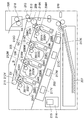
現像コントラストに対するトナーの供給量を確認する。確認の方法は、感光ドラムの周速を0.2m/sとし、現像ローラの周速を変化させることで、感光ドラムの周速に対する現像ローラの周速の比率である周速比を変えて行った。このときの周速比は、100%を等速度として、例えば、140%の場合、現像ローラの方が感光ドラムよりも速く回ることを意味する。なお、現像ローラの周速を0.2m/sで一定に固定し、感光ドラムの周速を遅くすることで、周速比を大きくするように構成してもよい。また、色味と濃度は関係性が深いことから、本実施例の説明においては、濃度を用いて説明を行う。また、本検討で用いたトナーは黒色トナーにて行った。その結果を図1に示す。 Check the amount of toner supplied with respect to the development contrast. The confirmation method is to set the peripheral speed of the photosensitive drum to 0.2 m / s and change the peripheral speed of the developing roller to change the peripheral speed ratio, which is the ratio of the peripheral speed of the developing roller to the peripheral speed of the photosensitive drum. went. The peripheral speed ratio at this time means that the developing roller rotates faster than the photosensitive drum in the case of, for example, 140%, where 100% is the constant speed. The peripheral speed of the developing roller may be fixed at 0.2 m / s, and the peripheral speed of the photosensitive drum may be slowed down to increase the peripheral speed ratio. In addition, since the color and the density are closely related, the density will be used in the description of this embodiment. The toner used in this study was black toner. The result is shown in FIG.
図1aは、横軸に周速比、縦軸に像担持体としての感光ドラム上に現像されたM/Sを示してある。図1bは、同じく横軸に周速比、縦軸に感光ドラム上に現像されたトナーのQ/Sを示してある。図1に示すように、周速比210%付近でM/SとQ/Sの延びが周速比に対し鈍化していることが分かる。また、現像コントラストΔVを150Vとした場合の周速比とM/SまたはQ/Sとの関係を、破線で示した。この鈍化は、帯電されたトナーが感光ドラムに供給されると、現像コントラストで形成される電気的勾配が、トナーの持つ電荷によって緩やかに、もしくは勾配が解消され、感光ドラムの明部電位部に対するトナーの供給が飽和状態となっていることを示している。 In FIG. 1a, the horizontal axis shows the peripheral speed ratio, and the vertical axis shows the M / S developed on the photosensitive drum as an image carrier. In FIG. 1b, the horizontal axis shows the peripheral speed ratio, and the vertical axis shows the Q / S of the toner developed on the photosensitive drum. As shown in FIG. 1, it can be seen that the extension of M / S and Q / S slows down with respect to the peripheral speed ratio at around 210% of the peripheral speed ratio. Further, the relationship between the peripheral speed ratio and M / S or Q / S when the development contrast ΔV is 150 V is shown by a broken line. This blunting occurs when the charged toner is supplied to the photosensitive drum, the electrical gradient formed by the development contrast is gradually reduced or eliminated by the charge of the toner, and the gradient is eliminated with respect to the bright potential portion of the photosensitive drum. This indicates that the toner supply is saturated.
現像ニップ部での現像コントラストは、感光ドラムに形成された静電潜像を構成する明部電位及び暗部電位と、現像ローラに印加された現像バイアスとで形成される。この現像コントラストによって、現像ローラ上のトナーは感光ドラムへ移動し静電像を現像する。現像コントラストによって現像に供されるトナーの量(現像可能量)は、供給されたトナーの帯電電荷量の総量に対し、トナーが狭持される現像ニップ部における感光ドラムと現像ローラ間の静電容量(C)と現像コントラスト(ΔV)の積で決められる。つまり、C×ΔVが、現像ローラと感光ドラムが対向する対向部である現像ニップ部で現像ローラから感光ドラムへ移動可能(現像に供されることが可能)な単位面積当たりのトナーの帯電電荷量の総量を表している。また、感光ドラムに供給されるトナーの帯電電荷の総量は、現像ローラ上の単位面積当たりの帯電電荷量(Q/S)と感光ドラムに対する周速比(Δv)に応じて決まり、Q/S×Δvの積で表される。 The development contrast at the development nip is formed by the bright and dark potentials forming the electrostatic latent image formed on the photosensitive drum and the development bias applied to the development roller. Due to this development contrast, the toner on the developing roller moves to the photosensitive drum to develop the electrostatic image. The amount of toner (developable amount) provided for development by the development contrast is the electrostatic voltage between the photosensitive drum and the developing roller in the developing nip where the toner is held narrower than the total amount of charged charge of the supplied toner. It is determined by the product of the capacitance (C) and the development contrast (ΔV). That is, C × ΔV is the charge charge of the toner per unit area that can be moved from the developing roller to the photosensitive drum (can be used for development) at the developing nip portion where the developing roller and the photosensitive drum face each other. It represents the total amount of quantity. The total amount of charged charge of the toner supplied to the photosensitive drum is determined according to the amount of charged charge per unit area on the developing roller (Q / S) and the peripheral speed ratio (Δv) to the photosensitive drum, and is Q / S. It is represented by the product of × Δv.
以上のことから、現像コントラストに対し現像に供することが可能なトナー量は、|Q/S×Δv|=|C×ΔV|の関係式で表される。つまり、周速比Δvを変化させ、|Q/S×Δv|≦|C×ΔV|となった場合、現像ローラから供給されるトナーの総電荷量が、感光ドラムが受け取れる電荷量よりも少ないことになる。この場合が、現像ローラ上の全てのトナーが感光ドラムへ移動する(現像に供される)条件となる。逆に、|Q/S×Δv|>|C×ΔV|の場合、現像ローラから供給されるトナーの総電荷量が、感光ドラムが受け取れる電荷量よりも多いことになる。この場合が、現像ローラ上のトナーは感光ドラムへ移動した後、一部のトナーは現像に用いられるが、残りのトナーは現像に用いられずに現像ローラ上に残る条件となる。 From the above, the amount of toner that can be used for development with respect to the development contrast is represented by the relational expression | Q / S × Δv | = | C × ΔV |. That is, when the peripheral speed ratio Δv is changed and | Q / S × Δv | ≦ | C × ΔV |, the total charge amount of the toner supplied from the developing roller is smaller than the charge amount received by the photosensitive drum. It will be. This case is a condition for all the toner on the developing roller to move to the photosensitive drum (used for development). On the contrary, in the case of | Q / S × Δv |> | C × ΔV |, the total charge amount of the toner supplied from the developing roller is larger than the charge amount received by the photosensitive drum. In this case, after the toner on the developing roller is moved to the photosensitive drum, some toner is used for development, but the remaining toner is not used for development and remains on the developing roller.
図1に示すように、ΔV=200Vの場合、Δv=210[%]の条件下で感光ドラム上のM/Sは鈍化し、Q/S×Δvが−0.32×10−3程度となる。したがって、|Q/S×Δv|=|C×ΔV|の関係から、感光ドラムと現像ローラ間の容量の積である静電容量Cは、1.6×10−6となる。 As shown in FIG. 1, when ΔV = 200V, the M / S on the photosensitive drum is blunted under the condition of Δv = 210 [%], and Q / S × Δv is about −0.32 × 10 -3. Become. Therefore, from the relationship of | Q / S × Δv | = | C × ΔV |, the capacitance C, which is the product of the capacitances between the photosensitive drum and the developing roller, is 1.6 × 10⁻⁶ .
感光ドラム上に現像されたトナー像は最終的に記録材上へ転移・定着される。そのときのトナーの現像量と濃度の関係を示したのが図4である。図1と図4から、周速比を120%とすると、一般的にオフィス文書で必要とされる濃度1.45(Macbeth RD−918)を得られることが確認された。さらに周速比を上昇させると、周速比200
%で濃度1.72まで達し、それ以降も変化はあるものの、その変化量は大きくはないことが分かった。そこで、本実施例では、第1の周速比として、オフィス用途などを目的とした通常モード(モードA)における周速比を濃度1.45が出力される120%とした。例えば、感光ドラムの周速が200mm/secの場合、現像ローラの周速は240mm/secとなる。また、第2の周速比として、本実施例の高濃度モード(モードB)では、濃度を1.7以上出しつつ現像残トナーが生じる条件として、周速比を240%とした。例えば、感光ドラムの周速が200mm/secの場合、現像ローラの周速は580mm/secとなる。なお、本実施例では、接触部C1において感光ドラム201と現像ローラ302とが同じ方向に回転するため、周速比が正の値になる。したがって、接触部C1において感光ドラム201と現像ローラ302とが逆の方向(対向方向)に回転するような装置構成の場合は、周速比は負の値になる。本実施例では、感光ドラムと現像ローラとが接触している接触部を基準に周速比を求めている。しかし、これに限定されず、感光ドラムと現像ローラとが接触しない装置構成の場合は、感光ドラムと現像ローラとの最近接距離に対応する位置を対向部とし、この対向部を基準に回転方向を特定して周速比を出してもよい。上記条件により、ベタ黒画像などの高印字パターンの現像後においても現像ローラ上にトナーが残る状態となることが確認された。また、濃度は1.75が出力され、十分高い濃度であることを確認し、現像後の現像ローラ上に残るトナーのM/Sは、大凡0.4×10−3kg/m2であった。一方、比較例として、高濃度モードでの周速比を従来の現像残が残らない周速比であるΔv=200%とし、濃度は1.72程度を得つつベタ黒画像などの高印字パターンを形成した場合に現像後の現像ローラ上には残トナーが無い状態であることを確認した。
The toner image developed on the photosensitive drum is finally transferred and fixed on the recording material. FIG. 4 shows the relationship between the developed amount and the density of the toner at that time. From FIGS. 1 and 4, it was confirmed that when the peripheral speed ratio is 120%, the concentration 1.45 (Macbeth RD-918) generally required for office documents can be obtained. When the peripheral speed ratio is further increased, the peripheral speed ratio is 200.
It was found that the concentration reached 1.72 in%, and although there was a change after that, the amount of change was not large. Therefore, in this embodiment, as the first peripheral speed ratio, the peripheral speed ratio in the normal mode (mode A) for office use or the like is set to 120% at which a concentration of 1.45 is output. For example, when the peripheral speed of the photosensitive drum is 200 mm / sec, the peripheral speed of the developing roller is 240 mm / sec. As a second peripheral speed ratio, in the high density mode (mode B) of this embodiment, the peripheral speed ratio was set to 240% as a condition for generating undeveloped toner while producing a density of 1.7 or more. For example, when the peripheral speed of the photosensitive drum is 200 mm / sec, the peripheral speed of the developing roller is 580 mm / sec. In this embodiment, since the
それぞれのモードにおいて、A4サイズの用紙を用いて全面ベタ黒画像を連続的に50枚印刷し、そのときのベタ濃度の変化やムラの有無を確認した。また、ベタ濃度の測定はA4紙の四隅を濃度測定器にて測定を行い、頁内での濃度ムラが0.1以内であれば、視認性は低い為「○」とし、それ以外を「×」とした。その結果を表1に示す。
[表1]

[Table 1]
表1については、関係式とともに現像残の有無も示した。表1に示すように、実施例では、連続50枚において、それぞれの濃度を維持しつつ、頁内の濃度ムラレベルも良好な結果であった。それに対し、従来例である比較例においては、20枚目から画像後端部に濃度ムラを確認した。濃度ムラのレベルは完全に画像が消失する白抜けのレベルではなく、全体的な濃度が1.7に対し、後端部が1.4から1.6程度のモヤ画像のような状態であった。 Table 1 shows the presence or absence of development residue as well as the relational expression. As shown in Table 1, in the examples, the density unevenness level in the page was also a good result while maintaining the respective concentrations in 50 consecutive sheets. On the other hand, in the comparative example which is a conventional example, density unevenness was confirmed at the rear end of the image from the 20th image. The level of density unevenness is not the level of white spots where the image disappears completely, but the overall density is 1.7, while the rear end is in a state like a muddy image of about 1.4 to 1.6. It was.
本実施例によれば、ベタ画像の形成において、従来のように現像残トナーが生じないような動作条件ではなく、現像残トナーが形成されるような動作条件を採用することで、連続して画像形成を行う場合における濃度安定性を得ることが可能となる。これは、トナーの供給量を増やして、現像ローラへ付着する過程で電荷を付与されたトナーを一部を現像残りトナーとしての残すことで、現像残りトナーの電荷に引き寄せられたトナーの現像ローラへの付着が進み、濃度ムラが生じにくくなったと考察される。なお、本実施例におけ
る現像残りトナーを形成する現像設定では、前述した印加バイアスの変動による濃度ムラが懸念される。しかしながら、図4に示すように、高濃度域ではM/S変動が生じた場合においても、濃度変動としては少ないことから、印加バイアスの変動による濃度変化は影響が少ない。
According to this embodiment, in forming a solid image, by adopting an operating condition in which undeveloped toner is formed instead of an operating condition in which undeveloped toner is not generated as in the conventional case, continuous development is performed. It is possible to obtain density stability when image formation is performed. This is because the supply amount of toner is increased and a part of the toner charged in the process of adhering to the developing roller is left as the developing residual toner, so that the developing roller of the toner attracted to the charge of the developing residual toner is attracted. It is considered that the adhesion to the toner has progressed and the density unevenness has become less likely to occur. In the development setting for forming the residual development toner in this embodiment, there is a concern about density unevenness due to the above-mentioned fluctuation of the applied bias. However, as shown in FIG. 4, even when the M / S fluctuation occurs in the high concentration region, the concentration fluctuation is small, so that the concentration change due to the fluctuation of the applied bias has little influence.
以上、本実施例では、高濃度モードや色味の増大を目的としたモードを採用する際、制御部であるCPU215は、|Q/S×Δv|=|C×ΔV|の関係性に基づいて、周速比Δvを調整し、現像ローラ上に現像残りトナーを形成する。これにより、高濃度画像においても濃度ムラを生じさせることなく、安定的に印刷することが可能となる。なお、本実施例で説明した各種動作設定は、あくまで一例である。重要なのは、感光ドラムの明部電位と現像バイアスとで形成される現像コントラストを、現像の際に帯電電荷を持ったトナーで無くしきれるかどうか(現像残トナーを形成できるかどうか)であり、それが満たされる限り、他の設定条件でもよい。
As described above, in this embodiment, when the high density mode or the mode for increasing the color tone is adopted, the
[色域の拡大についての説明]
図5は、本実施例における、通常モードでカラー画像を形成する場合の色域と、高濃度モードでカラー画像を形成する場合の色域と、を比較して示した色度図である。色域の評価として、L*a*b*表色系(CIE)を用いた。また、色度の測定は、X−Rite製SPECTORDENSITOMETER 500を用いて測定した。図5は、本発明の高濃度モードにおける制御を、カラー画像形成における基本色であるイエロー(Y)、マゼンタ(Mg)、シアン(Cy)の各プロセスカートリッジにおいて同じように実施したときの、色域の変化を示している。通常モードから高濃度モードに切り替えることで、例えば、イエロー(Y)とマゼンタ(Mg)とで形成されるレッド(R)の色域や、イエロー(Y)とシアン(Cy)とで形成されるグリーン(G)の色域が拡大していることがわかる。
[Explanation of color gamut expansion]
FIG. 5 is a chromaticity diagram showing a comparison between the color gamut when a color image is formed in the normal mode and the color gamut when a color image is formed in the high density mode in this embodiment. As an evaluation of the color gamut, L * a * b * color system (CIE) was used. The chromaticity was measured using a SPECTORDENSITOMETER 500 manufactured by X-Rite. FIG. 5 shows the colors when the control in the high density mode of the present invention is similarly performed on the yellow (Y), magenta (Mg), and cyan (Cy) process cartridges, which are the basic colors in color image formation. It shows the change of the gamut. By switching from the normal mode to the high density mode, for example, the color gamut of red (R) formed by yellow (Y) and magenta (Mg) and the color gamut of yellow (Y) and cyan (Cy) are formed. It can be seen that the color gamut of green (G) is expanding.
なお、高濃度モードとしては、特定の色味の色域だけ拡大するような場合にも本発明は適用可能である。例えば、マゼンタ(Mg)とシアン(Cy)とで形成されるブルー(B)の色域だけを拡大する場合、4つのプロセスカートリッジのうちマゼンタとシアンのプロセスカートリッジにだけ本発明の高濃度モードを実施するようにしてよい。これにより、トナー供給量の不足を発生させずに、より確実に特定の色味の色域拡大を実現することができる。また、色味の調整において、単位面積当たりのトナーの載り量を増やす割合を、プロセスカートリッジ間で異なるように制御するような場合にも、本発明は適用可能である。すなわち、プロセスカートリッジ間における単位面積当たりのトナーの載り量の比率を所定の比率にすべく高濃度モードを実施する際に、本発明の制御を実施することで、トナー供給量を不足させることなく、上記所定比率をより確実に実現することができる。これにより、さらに細かい色味の調整を確実に実施することが可能となる。 As the high density mode, the present invention can be applied even when the color gamut of a specific tint is expanded. For example, when expanding only the blue (B) color gamut formed by magenta (Mg) and cyan (Cy), the high-concentration mode of the present invention is applied only to the magenta and cyan process cartridges out of the four process cartridges. It may be done. As a result, it is possible to more reliably expand the color gamut of a specific color without causing a shortage of toner supply amount. The present invention can also be applied to a case where the ratio of increasing the amount of toner loaded per unit area is controlled to be different between process cartridges in adjusting the color tone. That is, by performing the control of the present invention when the high concentration mode is carried out in order to set the ratio of the amount of toner loaded per unit area between the process cartridges to a predetermined ratio, the amount of toner supplied is not insufficient. , The above-mentioned predetermined ratio can be realized more reliably. This makes it possible to reliably perform finer color adjustment.
(実施例2)
上記実施例1では、高濃度モードを実施する際に、ベタ黒などの高印字パターン印刷時においても現像ローラにトナーが残るような動作条件とし、現像ローラへのトナーの供給性を維持しつつ濃度や色味の安定化を実現した。本発明の実施例2では、環境条件や仕様に伴うトナーの変化に応じてトナーの帯電電荷量が変化した場合において、その変化に対応した周速比制御を行い、条件等の変化にかかわらず同様の効果を得られるようにした。具体的には、実施例2に係る画像形成装置は、温度・湿度を検知する検知手段としてのセンサ219を備える(図2参照)。そして、CPU315は、センサ219の検知温度が所定の閾値温度以下、かつ検知湿度が所定の閾値湿度以下の場合には、低温・低湿環境として、後述する低温・低湿環境において必要な制御を行う。一方、CPU315は、センサ219の検知温度が所定の閾値温度以上、かつ検知湿度が所定の閾値湿度以上の場合には、高温・高湿環境として、後述する低温・低湿環境において必要な制御を行う。なお、
ここでは実施例2において実施例1と異なる点についてのみ説明する。実施例2においてここで説明しない事項は実施例1と同様である。
(Example 2)
In the first embodiment, when the high density mode is performed, the operating conditions are such that the toner remains on the developing roller even when printing a high printing pattern such as solid black, while maintaining the supply of toner to the developing roller. Achieved stabilization of density and color. In Example 2 of the present invention, when the amount of charged charge of the toner changes according to the change of the toner due to the environmental conditions and specifications, the peripheral speed ratio control corresponding to the change is performed, regardless of the change of the conditions and the like. The same effect can be obtained. Specifically, the image forming apparatus according to the second embodiment includes a
Here, only the points different from the first embodiment in the second embodiment will be described. Items not described here in the second embodiment are the same as those in the first embodiment.
初めに上記実施例1の構成において、トナーの帯電電荷が得にくい高温・高湿環境及び、トナーの帯電電荷を得やすい低温・低湿環境にて、濃度ムラと現像残の有無を確認した。その結果が、表2である。
[表2]
[Table 2]
本実施例では、常温・常湿環境を、温度25℃、湿度60%RHの環境とし、低温・低湿環境を、温度15℃、湿度10%RHの環境とし、高温・高湿環境を、温度30℃、湿度80%RHの環境とした。低温・低湿環境であることを判断するための閾値を、温度20℃(第1閾値温度)、湿度30%RH(第1閾値湿度)とし、検出値が温度20℃以下かつ湿度30%RH以下のときに、CPU315は、装置環境が低温・低湿環境と判断するようにした。また、高温・高湿環境であることを判断するための閾値を、温度28℃(第2閾値温度)、湿度70%RH(第2閾値湿度)とし、検出値が温度28℃以上かつ湿度70%RH以上のときに、CPU315は、装置環境が高温・高湿環境と判断するようにした。なお、トナー帯電電荷へ影響を与える温湿度の境界としては、トナーの材質や装置構成等に応じて適宜変更されるものである。表2に示すように、高温・高湿環境下では、濃度は常温・常湿環境下に対し若干濃いものの1.7程度であるが、現像残トナー量が無くなってしまい、濃度ムラが生じてしまった。また、低温・低室環境下では、濃度ムラは発生しないものの、濃度が常温・常湿環境下に対し若干低下し1.65程度となっていた。
In this embodiment, the room temperature / normal humidity environment is set to an environment of temperature 25 ° C. and
同様に、現像ローラ上のM/SやQ/Sについても確認する。その結果が表3である。[表3]
表3から、常温・常湿環境下に比べ、M/Sは変化していないものの、Q/Sが変化している。つまり、トナー単位重量当たりの帯電電荷量(以下Q/Mといい、Q/M=(Q/S)/(M/S)で表される)が変化している。具体的には、高温・高湿環境下ではQ/Mが低下し、低温・低室環境下ではQ/Mが上昇している。上記変化によって、実施例1で説明したように、関係式|Q/S×Δv|=|C×ΔV|のQ/Sが変化することで、現像可能なトナー量および現像後の現像ローラ上の残り量が変化した結果である。そこで、環境が変化しトナーのQ/Mが変化した場合においても、濃度および現像後の現像ローラ上の残トナー量を一定に保つために、現像コントラストを適正化させる。 From Table 3, the M / S has not changed, but the Q / S has changed as compared with the normal temperature / humidity environment. That is, the amount of charged charge per unit weight of toner (hereinafter referred to as Q / M, represented by Q / M = (Q / S) / (M / S)) is changing. Specifically, the Q / M decreases in a high temperature / high humidity environment, and increases in a low temperature / low room environment. As described in Example 1, the Q / S of the relational expression | Q / S × Δv | = | C × ΔV | changes due to the above change, so that the amount of toner that can be developed and the developing roller after development are changed. This is the result of the change in the remaining amount of. Therefore, even when the environment changes and the Q / M of the toner changes, the development contrast is optimized in order to keep the density and the amount of residual toner on the developing roller constant after development.
実施例1で述べたように、常温・常湿環境下での現像コントラストは、第1の現像コントラストとしてΔV=200Vである。一方、Q/Sの変化および関係式|Q/S×Δv|=|C×ΔV|からΔVを算出すると、第3の現像コントラストとしての高温・高湿環
境下でのΔVは、常温・常湿環境下に比べて小さくなり、180Vとなった。同様に、第2の現像コントラストとしての低温・低室環境下でのΔVは、260Vとなった。上記条件の現像コントラストΔVを本実施例では、レーザ光量を微調して行った。すなわち、現像バイアスを−300V、暗部電位を−500Vに固定(すなわち帯電バイアスを固定)し、レーザ光量の増減で変化する明部電位を常温・常湿環境下における−100Vから変化させることで、現像コントラストΔVを所望の値に調整した。その結果を、表4に示す。なお、現像コントラストΔVの変更は、レーザ光量の調整に代えて、現像バイアスや帯電バイアスの調整によって行ってもよいし、あるいはレーザ光量の調整とともにそれらも調整することで変更するようにしてもよい。
[表4]
[Table 4]
表4より、レーザ光量を微調して現像コントラストを変化させることで、現像残トナーを常温・常湿環境下と同様に形成することが可能となった。その効果として、濃度変化の抑制が可能となったとともに、濃度ムラの発生も抑制できることを確認した。 From Table 4, by finely adjusting the amount of laser light to change the development contrast, it became possible to form the development residual toner in the same manner as in a normal temperature / humidity environment. As an effect, it was confirmed that it was possible to suppress the change in concentration and also to suppress the occurrence of uneven concentration.
本実施例では、環境変動に伴うトナーの帯電電荷量(Q/M)が変化した場合、現像コントラストをレーザ光量にて適宜調整することで、濃度や濃度ムラに対し同様の効果が得られることを説明したが、この手法に限定されるものではない。上述したように、現像コントラストを調整する手段としては、例えば、帯電バイアスや現像バイアスを調整することで同様の効果が得られる。また、トナーの帯電電荷量(Q/M)の変化は、環境変化のみによらず、例えば、使用度によっても変化し、使用度の変化に応じて、同様の対応を行うことで、同様の効果を得ることもできる。 In this embodiment, when the amount of charge (Q / M) of the toner changes due to environmental changes, the same effect can be obtained for density and density unevenness by appropriately adjusting the development contrast with the amount of laser light. However, the method is not limited to this method. As described above, as a means for adjusting the development contrast, for example, the same effect can be obtained by adjusting the charging bias and the development bias. Further, the change in the charged charge amount (Q / M) of the toner changes not only by the environmental change but also by, for example, the degree of use, and the same measures are taken according to the change in the degree of use. You can also get the effect.
(実施例3)
図7は、本発明の実施例3に係る画像形成装置の概略断面図である。実施例3に係る画像形成装置200は、実施例1に係る画像形成装置の構成に加え、記録材207の副走査方向の幅を検知する記録材種検知センサ220と、記録材207の主走査方向の幅を検知する記録材種検知センサ221と、を備えている。ここでは実施例3において実施例1、2と異なる点についてのみ説明する。実施例3においてここで説明しない事項は実施例1、2と同様である。
(Example 3)
FIG. 7 is a schematic cross-sectional view of the image forming apparatus according to the third embodiment of the present invention. In the
図8は、実施例3に係る画像形成装置の感光ドラム201、現像ローラ302の駆動、及び高圧制御におけるブロック図である。図8より、エンジンコントローラ214のCPU215から各電圧印加部401、402、各モータ駆動部403、404に信号を送っている。まず、CPU215は、帯電電圧印加部401に信号を送り帯電ローラ202に直流電圧が印加され、感光ドラム201との間で放電させることで感光ドラム201表面上に一様の暗部電位(Vd)を形成する。スキャナユニット203内のレーザ217によって画像データに対応して発光されるレーザ217のスポットパターンは、感光ドラム201を露光し、露光された部位は電位が低下し明部電位(Vl)となる。次に、CPU215は、現像電圧印加部402に信号を送り現像ローラ302に直流電圧が印加され、感光ドラム201の明部電位(Vl)にトナー305を転移させる。そのとき、感光ドラム201、現像ローラ302には、CPU215から感光ドラムモータ駆動部404、現像
ローラモータ駆動部403に信号を送り、各ローラを所望回転数で駆動を行っている。記録材207の種類は、記録材207の主走査、副走査方向の記録材幅を検知するセンサ(220、221)の検出値により、CPU215にて検知される。
FIG. 8 is a block diagram of the
図9は、実施例3における、感光ドラム201の周速に対する現像ローラ302の周速の比率である周速比と、ベタ黒画像を印字した場合の現像ローラ302から感光ドラム201へのトナー供給量[kg/m2]との関係を示す特性図である。図9より、周速比をアップすると現像ローラ302から感光ドラム201に供給されるトナー量は増加する。
FIG. 9 shows the peripheral speed ratio, which is the ratio of the peripheral speed of the developing roller 302 to the peripheral speed of the
図10は、現像ローラ302から感光ドラム201へのトナー供給量[kg/m2]と画像形成濃度との関係を示す特性図である。図10より、現像ローラ302から感光ドラム201に供給されるトナー量を増加させると、画像形成時の濃度がアップする。
FIG. 10 is a characteristic diagram showing the relationship between the toner supply amount [kg / m 2 ] from the developing roller 302 to the
図11は、現像コントラスト可変時の現像ローラ302から感光ドラム201へのトナー供給量[kg/m2]と、感光ドラム201に現像されたトナー帯電電荷量[C/m2]との関係を示す特性図である。図11より、現像コントラスト200V時には、ポイントAが、現像効率が100%となる設定、すなわち、現像ローラから感光ドラムへ供給されたトナーが全て感光ドラム上の静電像の現像に供される設定である。ポイントA以上になると現像効率が100%未満となる、すなわち、現像ローラから感光ドラムへ供給されたトナーの一部は静電像の現像に供されない。現像コントラスト250V、300Vの時は、それぞれポイントB、ポイントCが、現像効率が100%となる設定であり、それぞれポイントB、ポイントC以上で現像効率100%未満となる。
FIG. 11 shows the relationship between the toner supply amount [kg / m 2 ] from the developing roller 302 to the
即ち、例えば、現像コントラスト200V時には、ポイントAよりも更に現像ローラ302から感光ドラム201へのトナー供給量[kg/m2]を増やしたとしても、全てのトナーを使い切る前に感光ドラム201上の潜像電荷が埋まってしまう。したがって、供給されたトナーの一部は感光ドラム201上に移動せず(現像に用いられず)、供給量に対する現像使用量との関係において現像効率が下がる(現像効率100%未満)ことになる。なお、現像コントラスト250V、300Vにおいても、同様にポイントB、ポイントCより感光ドラム201へのトナー供給量を増やしても同様に現像効率が下がることになる。
That is, for example, at a development contrast of 200 V, even if the amount of toner supplied from the developing roller 302 to the photosensitive drum 201 [kg / m 2 ] is increased more than at point A, the toner is placed on the
現像コントラストは、感光ドラム201上の明部電位(Vl)と、現像ローラ302に印加された所定のDCバイアス(現像バイアス)とで形成され、現像ローラ302から感光ドラム201へトナーが移動していくと、小さくなっていく。現像ローラ302が担持する全てのトナーが感光ドラム201へ移動して現像に供され、そのトナーの電荷量[C/m2]によって現像コントラストが0Vとなると現像効率100%となる。ここで現像コントラストは、目標となる濃度に応じた現像ローラ302から感光ドラム201へのトナー305供給量kg/m2と、感光ドラム201に現像されたトナー電荷量[C/m2]等によって所望値が設定される。実施例3に係る画像形成装置が定常動作である通常モード(通常画像形成モード)で画像形成を行う際の各種動作設定を以下に示す。
The development contrast is formed by the bright potential (Vl) on the
[表5]
表5に示す通常モードでの動作設定は、次のように算出される。例えば、目標とする濃度設定を1.35とする。そうすると、図10より、濃度1.35とするためには、現像
ローラ302から感光ドラム201へのトナー供給量が0.003kg/m2必要となる。そして、図9より、上記トナー供給量を実現するためには、感光ドラム201の周速に対する現像ローラ302の周速の比率である周速比が145%となるように、現像ローラモータ駆動部403で現像ローラ302を駆動することが必要となる。また、上記トナー供給率において現像効率100%設定とするためには、図11より、現像コントラストは200Vの設定となる。
The operation settings in the normal mode shown in Table 5 are calculated as follows. For example, the target concentration setting is 1.35. Then, from FIG. 10, in order to obtain the concentration of 1.35, the amount of toner supplied from the developing roller 302 to the
上記設定によれば、ベタ黒等の高印字パターンにおいて、現像ローラ302に担持されるトナー305の電荷量に対し充分な静電潜像を形成し、現像ローラ302にコートされた全てのトナー305が感光ドラム201へ移動する現像効率100%を実現できる。そのため、現像ローラ302上のトナーコートは、現像後の残トナーがほとんど無くなるため、長尺紙等の画像形成が連続的に続く紙サイズ等を使用した場合に、紙後端に追従性不良(濃度ムラ/色ムラ等)が発生する懸念がある。そのため、実施例3では、オフィス等で使われる定常的な画像品質を実現する通常の画像形成モードと共に、ユーザの使用条件に応じて選択できる複数の画像形成モードを設定出来る構成とする。本実施例3では、ユーザが選択出来る複数の画像形成モードとして、複数の長尺紙、すなわち、記録材搬送方向における長さが相対的に長いサイズの複数の記録材に対して連続的に画像形成を行う場合の動作モードである長尺紙モードを設けている。
According to the above settings, in a high printing pattern such as solid black, an electrostatic latent image sufficient for the amount of charge of the
図6は、実施例3における画像形成動作時のフローチャート図である。図6より、ユーザが画像形成モードを選択(画像形成装置に画像形成動作の実行を指示)し(102)、ユーザがモード選択を行わなければ(103:No)、CPU215は、通常画像形成モードを選択し(104)、画像形成動作を開始する(105)。ユーザが長尺紙画像形成モードを選択した場合(103:Yes)、CPU215は、長尺紙画像形成モードで画像形成を開始する(106、107)。以下に、実施例3においてユーザが長尺紙画像形成モードを選択したときの画像形成の動作設定を示す。
FIG. 6 is a flowchart of the image forming operation in the third embodiment. From FIG. 6, unless the user selects the image forming mode (instructs the image forming apparatus to execute the image forming operation) (102) and the user does not select the mode (103: No), the
[表6]
表6に示す長尺紙モードでの動作設定は次のように算出される。上述した、複数の長尺紙に連続的に画像形成を行う場合に発生する紙後端の追従性不良は、現像効率を100%に設定して、現像ローラ302にコートされたトナー305を全て感光ドラム201に移動させてしまうことで発生する。連続画像形成の後半において現像ローラ302から感光ドラム201へのトナー305の供給が追従出来なくなるである。そのため、上記に示す長尺紙モードでは、感光ドラム201対現像ローラ302の周速比をアップさせて現像ローラ302上のトナーコート量を増やし、現像ローラ302から感光ドラム201へのトナー305の供給を追従させることが必要となる。
The operation settings in the long paper mode shown in Table 6 are calculated as follows. As for the above-mentioned poor followability of the rear edge of the paper that occurs when continuously forming an image on a plurality of long papers, the development efficiency is set to 100% and all the
ここで、現像ローラ302から感光ドラム1へのトナー供給追従性を向上させるためには、現像効率を100%未満の設定とする必要がある。現像効率を100%未満とすることで、現像後の現像ローラ302上にトナー305が残り、残ったトナー305の電荷量によって、供給ローラ304から現像ローラ302に供給されるトナー305のより多くを現像ローラ302に引きつける効果が働く。これにより、現像ローラ302のトナーコート量を連続画像形成中の長期にわたって維持することができ、現像ローラ302から感光ドラム1へのトナー供給追従性が向上する。
Here, in order to improve the toner supply followability from the developing roller 302 to the photosensitive drum 1, it is necessary to set the developing efficiency to less than 100%. By setting the development efficiency to less than 100%, the
そこで、現像効率を100%未満とし現像ローラ302上に現像残トナーを残し、現像ローラ302からのトナー305追従を満足させるため、感光ドラム201の周速に対する現像ローラ302の周速の比率(周速比)を上げる。周速アップ量は次のように求める。例えば、現像効率100%未満の設定として現像効率を75%とした場合、図11より、現像効率75%とするための現像ローラ302から感光ドラム201へのトナー供給量は0.004kg/m2となる。そして、該トナー供給量を実現するための、感光ドラム201に対する現像ローラ302の周速比設定は、図9より、193%となる。したがって、該周速比となるように、制御部であるCPU215が、現像ローラモータ駆動部403で現像ローラ302を駆動すればよいことがわかる。
Therefore, in order to set the development efficiency to less than 100%, leave the residual development toner on the developing roller 302, and satisfy the follow-up of the
上記長尺紙モードに設定することで、副走査方向の幅(長さ)が1200mmの長尺紙を使用した場合に、通常モードで発生していた紙後端の追従性不良(濃度ムラ/色ムラ等)を抑制することができる。なお、通常モードは、主としてA5、A4などの定形サイズの記録材における画像形成を想定した動作モードである。 By setting the long paper mode, when long paper with a width (length) of 1200 mm in the sub-scanning direction is used, the followability of the rear edge of the paper (density unevenness / density unevenness / Color unevenness, etc.) can be suppressed. The normal mode is an operation mode mainly assuming image formation in a recording material of a fixed size such as A5 or A4.
以上のように、実施例3では、定常的な画像品質を実現する画像形成モードと供に、ユーザの使用条件に応じて選択出来る複数の画像形成モードの1つとして、長尺紙モードを設けている。そして、上述した実施例3の動作設定を採用することで、複数の長尺紙に連続的に画像形成を行った場合において、通常の画像形成モードでは発生することがあった紙後端の追従性不良(濃度ムラ/色ムラ等)の発生を抑制することができる。実施例3では、長尺紙モードの選択をユーザが選択する構成としたが、同様の効果が得られれば当該構成に限定されるものではなく、例えば、画像形成装置200が自ら紙種を検知し、CPU215が自動で長尺紙モードに選択できるようにしてもよい。
As described above, in the third embodiment, a long paper mode is provided as one of a plurality of image forming modes that can be selected according to the user's usage conditions, in addition to the image forming mode that realizes steady image quality. ing. Then, by adopting the operation setting of the third embodiment described above, when image formation is continuously performed on a plurality of long papers, the tracking of the rear edge of the paper, which may occur in the normal image formation mode, is followed. It is possible to suppress the occurrence of poor quality (uneven density / uneven color, etc.). In the third embodiment, the user selects the long paper mode, but the present invention is not limited to this configuration as long as the same effect is obtained. For example, the
実施例3では、現像ローラモータ駆動部及び感光ドラムモータ駆動部をそれぞれ共通化、すなわち一つのモータで4つの現像ローラを回転させ、別の一つのモータで4つの感光ドラムを回転させる構成としたが、駆動構成はこれに限定されるものではない。上述した長尺紙モードにおける動作設定を実現することができる構成であれば、例えば、各現像ローラ、各感光ドラムがそれぞれ独自のモータによって回転駆動される構成等でもよい。 In the third embodiment, the developing roller motor drive unit and the photosensitive drum motor driving unit are shared, that is, one motor rotates four developing rollers and another motor rotates four photosensitive drums. However, the drive configuration is not limited to this. As long as the operation setting in the long paper mode described above can be realized, for example, each developing roller and each photosensitive drum may be rotationally driven by a unique motor.
また、感光ドラム201と現像ローラ302の周速設定を、現像ローラ302の回転数を変えて設定していたが、現像ローラ302の回転数は固定し、感光ドラム201の回転数を変えることで周速比を可変にしてもよい。あるいは、現像ローラ302の回転数と感光ドラム201の回転数の両方を変えて、周速比を可変制御してもよい。その場合、現像ローラ302の回転数と感光ドラム201の回転数の両方を低下させ、かつ、その下げ幅に差をつけることで、周速比を変えるようにしてもよい。
Further, the peripheral speed setting of the
また、長尺紙モードでの動作設定値として、実施例3では、現像コントラストを200V、周速比を193%、現像効率を75%としたが、適切な設定値は装置構成や動作条件等に応じて当然に異なることがある。実施例3と同様の効果が得られるものであれば、各設定値は適宜変更され得る。 Further, as the operation setting values in the long paper mode, in Example 3, the development contrast was set to 200V, the peripheral speed ratio was set to 193%, and the development efficiency was set to 75%. Of course, it may differ depending on the situation. Each set value can be changed as appropriate as long as the same effect as in Example 3 can be obtained.
(実施例4)
上記実施例3では、色味の選択範囲の増大や高濃度を得るための複数の画像形成モードのうち、濃度は通常モードと同様の値を維持しつつ長尺紙に対応するための長尺紙モードについて述べた。それに対して、本発明の実施例4では、ユーザが選択可能なさらに別の動作モードとして、色味の選択範囲の増大や高濃度を得るための高濃度モードを備え、該モードにおける各種動作設定を追従性不良(濃度ムラ/色ムラ等)を発生させない設定とした。ここでは実施例4において実施例3と異なる点についてのみ説明する。実施例4に
おいてここで説明しない事項は実施例3と同様である。
(Example 4)
In the third embodiment, among the plurality of image forming modes for increasing the selection range of the color and obtaining the high density, the density is long to correspond to the long paper while maintaining the same value as the normal mode. The paper mode was mentioned. On the other hand, in the fourth embodiment of the present invention, as yet another operation mode that can be selected by the user, a high density mode for increasing the color selection range and obtaining a high density is provided, and various operation settings in the mode are provided. Was set so as not to cause poor followability (uneven density / uneven color, etc.). Here, only the points different from the third embodiment in the fourth embodiment will be described. Items not described here in the fourth embodiment are the same as those in the third embodiment.
図12は、本発明の実施例4における画像形成動作時のフローチャート図である。図12より、ユーザが、画像形成モードを選択(画像形成装置に画像形成動作の実行を指示)し(802)、モード選択を行わなければ(803:No、804:No)、CPU215は通常画像形成モードで画像形成動作を開始する(805、806)。ユーザが長尺紙画像形成モードを選択せず、かつ高濃度画像形成モードを選択した場合(803:No、804:Yes)、CPU215は、定形サイズ紙のための通常の高濃度画像形成モードで画像形成を開始する(807、808)。ユーザが長尺紙画像形成モードを選択し、かつ高濃度画像形成モードを選択した場合(803:Yes、812:Yes)、CPU215は、長尺紙のための高濃度画像形成モードで画像形成を開始(813、814)する。ユーザが長尺紙画像形成モードを選択し、かつ高濃度画像形成モードを選択しなかった場合(803:Yes、812:No)、CPU215は、実施例3で説明した長尺紙画像形成モードで画像形成を開始(809、810)する。以下に、実施例4においてユーザが高濃度画像形成モードを選択したときの画像形成の動作設定を示す。
FIG. 12 is a flowchart of the image forming operation according to the fourth embodiment of the present invention. From FIG. 12, unless the user selects the image forming mode (instructs the image forming apparatus to execute the image forming operation) (802) and does not select the mode (803: No, 804: No), the
[表7]
表7に示す高濃度モードでの動作設定は、次のように算出される。例えば、通常の高濃度モードでは、その目標濃度を、市場での要望を考慮して、1.75と設定する。そうすると、図10より、目標濃度1.75を満足するためには、現像ローラ302から感光ドラム201へのトナー供給量は0.007kg/m2必要となる。そして、図11より、感光ドラム201に現像ローラ302からトナーを0.007kg/m2転移させるためには、現像コントラスト300Vが必要となる。ここで、追従性不良(濃度ムラ/色ムラ等)を発生することなく、高濃度画像を印字するためには、現像効率を100%未満とする必要がある。そこで、現像ローラ302から感光ドラム201へのトナー305供給量を0.0075kg/m2と設定する。ここで、現像ローラ302から感光ドラム201へのトナー305供給量を0.0075kg/m2とするためには、図9より、感光ドラム201に対する現像ローラ302の周速比を360%とする必要がある。したがって、周速比が360%となるように、現像ローラ302を現像ローラモータ駆動部403にて駆動する。これにより、現像効率は93%となる。一方、長尺紙の高濃度モードでは、通常の高濃度モードと同じ目標濃度1.75、現像コントラスト300Vにおいて、トナー供給追従性を向上させるべく現像効率を100%未満とするために周速比を上げる。具体的には、周速比を483%まで上げ、現像効率を75%まで下げる。
The operation settings in the high density mode shown in Table 7 are calculated as follows. For example, in the normal high concentration mode, the target concentration is set to 1.75 in consideration of the demand in the market. Then, from FIG. 10, in order to satisfy the target density of 1.75, the amount of toner supplied from the developing roller 302 to the
上記高濃度モードに設定することで、長尺紙への画像形成において、トナー追従性不良(濃度ムラ/色ムラ等)を発生させることなく、濃度を1.35から1.75にアップすることができ、良好な高濃度画像を得ることができる。すなわち、実施例1で説明した高濃度モードによる色域拡大、色味の選択範囲の増大を、長尺紙においても画像不良を発生させることなく実現することができる。 By setting the high density mode, the density can be increased from 1.35 to 1.75 without causing poor toner followability (uneven density / uneven color, etc.) in image formation on long paper. It is possible to obtain a good high-density image. That is, it is possible to expand the color gamut and increase the color selection range by the high density mode described in the first embodiment without causing image defects even on long paper.
なお、通常の高濃度モードでの動作設定値として、実施例4では、濃度1.75、現像コントラスト300V、周速比360%、現像効率93%としたが、適切な設定値は装置構成や動作条件等に応じて当然に異なることがある。同様に、長尺紙の高濃度モードでの
動作設定値として、実施例4では、濃度1.75、現像コントラスト300V、周速比483%、現像効率93%としたが、適切な設定値は装置構成や動作条件等に応じて当然に異なることがある。実施例4と同様の効果が得られるものであれば、各設定値は適宜変更され得る。
In Example 4, the operation setting values in the normal high density mode were 1.75 density, 300 V development contrast, 360% peripheral speed ratio, and 93% development efficiency. Naturally, it may differ depending on the operating conditions and the like. Similarly, as the operation setting values of the long paper in the high density mode, in Example 4, the density was 1.75, the development contrast was 300 V, the peripheral speed ratio was 483%, and the development efficiency was 93%. Naturally, it may differ depending on the device configuration, operating conditions, and the like. Each set value can be changed as appropriate as long as the same effect as that of the fourth embodiment can be obtained.
200…画像形成装置、201…感光ドラム(像担持体)、202…帯電ローラ、214…CPU(制御手段)、305…トナー(現像剤)、302…現像ローラ(現像剤担持体)、401…帯電電圧印加部、402…現像電圧印加部、403…現像ローラモータ駆動部(駆動手段)、404…感光ドラムモータ駆動部(駆動手段) 200 ... Image forming apparatus, 201 ... Photosensitive drum (image carrier), 202 ... Charging roller, 214 ... CPU (control means), 305 ... Toner (developer), 302 ... Developing roller (developer carrier), 401 ... Charging voltage application unit, 402 ... Development voltage application unit, 403 ... Development roller motor drive unit (drive means), 404 ... Photosensitive drum motor drive unit (drive means)
Claims (17)
前記像担持体に形成された静電像を現像剤で現像する現像剤担持体と、
前記像担持体と前記現像剤担持体のそれぞれの周速を個々かつ可変に回転駆動する駆動手段と、
前記像担持体において、暗部電位から明部電位を形成することにより、前記像担持体に静電像を形成する潜像形成手段と、
前記現像剤担持体に現像バイアスを印加する印加手段と、
前記像担持体に対する前記現像剤担持体の周速比を第1の周速比にして、前記静電像を前記現像剤で現像する通常モードと、
前記像担持体と前記現像剤担持体との周速比を前記通常モードにおける前記第1の周速比よりも大きい第2の周速比とすることで、記録媒体に形成される画像の色域を前記通常モードよりも拡大する高濃度モードと、を実行可能な制御部と、
を備え、
前記駆動手段は、前記像担持体と前記現像剤担持体を、前記第1の周速比と、前記第2の周速比と、
で駆動可能であり、
前記現像剤担持体に担持された現像剤の単位面積当たりの電荷量をQ/Sとし、
前記周速比をΔvとしたとき、
前記通常モードにおける前記第1の周速比は、前記現像剤担持体から前記像担持体に移動する現像剤の帯電電荷量を表す|Q/S×Δv|が前記像担持体で受け取れる現像剤の単位面積当たりの電荷量よりも小さくなるように設定され、
前記高濃度モードにおける前記第2の周速比は、|Q/S×Δv|が前記像担持体で受け取れる現像剤の単位面積当たりの電荷量よりも大きくなるように設定されることを特徴とする画像形成装置。 Image carrier and
A developer carrier for developing an electrostatic image formed on the image carrier with a developer, and a developer carrier.
A driving means for individually and variably rotating the peripheral speeds of the image carrier and the developer carrier.
A latent image forming means for forming an electrostatic image on the image carrier by forming a bright potential from the dark potential in the image carrier.
An application means for applying a development bias to the developer carrier, and
A normal mode in which the peripheral speed ratio of the developer carrier to the image carrier is set to the first peripheral speed ratio and the electrostatic image is developed with the developer.
By setting the peripheral speed ratio between the image carrier and the developer carrier to a second peripheral speed ratio that is larger than the first peripheral speed ratio in the normal mode, the color of the image formed on the recording medium. A control unit that can execute a high-concentration mode that expands the range from the normal mode, and
With
The driving means uses the image carrier and the developer carrier as the first peripheral speed ratio and the second peripheral speed ratio.
Can be driven by
The amount of electric charge per unit area of the developer supported on the developer carrier was defined as Q / S.
When the peripheral speed ratio is Δv,
The first peripheral speed ratio in the normal mode represents the amount of charge charged of the developer moving from the developer carrier to the image carrier | Q / S × Δv | is a developer that can be received by the image carrier. Is set to be less than the amount of charge per unit area of
The second peripheral speed ratio in the high concentration mode is characterized in that | Q / S × Δv | is set to be larger than the amount of charge per unit area of the developer that can be received by the image carrier. Image forming device.
前記第1の周速比の場合では、前記像担持体の周速を前記第2の周速比の場合と同じようにし、
前記第2の周速比の場合では、前記第1の周速比の場合よりも前記現像剤担持体の周速を速くすることを特徴とする請求項1または2に記載の画像形成装置。 The driving means is
In the case of the first peripheral speed ratio, the peripheral speed of the image carrier is set to be the same as in the case of the second peripheral speed ratio.
The image forming apparatus according to claim 1 or 2, wherein in the case of the second peripheral speed ratio, the peripheral speed of the developer carrier is made faster than in the case of the first peripheral speed ratio.
前記第1の周速比の場合では、前記現像剤担持体の周速を前記第2の周速比の場合と同じようにし、
前記第2の周速比の場合では、前記第1の周速比の場合よりも前記像担持体の周速を遅くすることを特徴とする請求項1または2に記載の画像形成装置。 The driving means is
In the case of the first peripheral speed ratio, the peripheral speed of the developer carrier is set to be the same as in the case of the second peripheral speed ratio.
The image forming apparatus according to claim 1 or 2 , wherein in the case of the second peripheral speed ratio, the peripheral speed of the image carrier is slower than in the case of the first peripheral speed ratio.
前記第2の周速比の場合では、前記第1の周速比の場合よりも前記現像剤担持体の周速を遅くし、
前記第2の周速比の場合では、前記第1の周速比の場合よりも前記像担持体の周速を遅くし、
前記現像剤担持体の周速の下げ幅と前記像担持体の周速の下げ幅とを異ならせることで、前記第2の周速比を前記第1の周速比よりも大きくすることを特徴とする請求項1または2に記載の画像形成装置。 The driving means is
In the case of the second peripheral speed ratio, the peripheral speed of the developer carrier is made slower than in the case of the first peripheral speed ratio.
In the case of the second peripheral speed ratio, the peripheral speed of the image carrier is made slower than in the case of the first peripheral speed ratio.
By making the peripheral speed reduction width of the developer carrier different from the peripheral speed reduction width of the image carrier, the second peripheral speed ratio can be made larger than the first peripheral speed ratio. The image forming apparatus according to claim 1 or 2.
前記像担持体に形成された静電像を現像剤で現像する現像剤担持体と、
前記像担持体と前記現像剤担持体のそれぞれの周速を個々かつ可変に回転駆動する駆動手段と、
前記像担持体において、暗部電位から明部電位を形成することにより、前記像担持体に静電像を形成する潜像形成手段と、
前記現像剤担持体に現像バイアスを印加する印加手段と、
前記像担持体に対する前記現像剤担持体の周速比を第1の周速比にして、前記静電像を前記現像剤で現像する通常モードと、前記像担持体と前記現像剤担持体との周速比を前記通常モードにおける前記第1の周速比よりも大きい第3の周速比とすることで、前記第1の周速比で画像を形成する記録材よりも長い記録材に画像を形成することが可能な長尺紙モードと、を実行可能な制御部と、
を備え、
前記駆動手段は、前記像担持体と前記現像剤担持体を、前記第1の周速比と前記第3の周速比と、で駆動可能であり、前記現像剤担持体に担持された現像剤の単位面積当たりの電荷量をQ/Sとし、前記周速比をΔvとしたとき、
前記通常モードにおける前記第1の周速比は、前記現像剤担持体から前記像担持体に移動する現像剤の帯電電荷量を表す|Q/S×Δv|が前記像担持体で受け取れる現像剤の単位面積当たりの電荷量よりも小さくなるように設定され、
前記長尺紙モードにおける前記第3の周速比は、|Q/S×Δv|が前記像担持体で受
け取れる現像剤の単位面積当たりの電荷量よりも大きくなるように設定されることを特徴とする画像形成装置。 Image carrier and
A developer carrier for developing an electrostatic image formed on the image carrier with a developer, and a developer carrier.
A driving means for individually and variably rotating the peripheral speeds of the image carrier and the developer carrier.
A latent image forming means for forming an electrostatic image on the image carrier by forming a bright potential from the dark potential in the image carrier.
An application means for applying a development bias to the developer carrier, and
A normal mode in which the peripheral speed ratio of the developer-bearing body to the image-bearing body is set to the first peripheral speed ratio to develop the electrostatic image with the developer, and the image-bearing body and the developer-supporting body. By setting the peripheral speed ratio of the third peripheral speed ratio to a third peripheral speed ratio that is larger than the first peripheral speed ratio in the normal mode, the recording material is longer than the recording material that forms an image at the first peripheral speed ratio. A long paper mode that can form an image, a control unit that can execute, and
With
The driving means can drive the image carrier and the developer carrier with the first peripheral speed ratio and the third peripheral speed ratio, and the development supported on the developer carrier can be driven. When the amount of charge per unit area of the agent is Q / S and the peripheral speed ratio is Δv,
The first peripheral speed ratio in the normal mode represents the amount of charge charged of the developer moving from the developer carrier to the image carrier | Q / S × Δv | is a developer that can be received by the image carrier. Is set to be less than the amount of charge per unit area of
The third peripheral speed ratio in the long paper mode is characterized in that | Q / S × Δv | is set to be larger than the amount of electric charge per unit area of the developer that can be received by the image carrier. Image forming apparatus.
前記第1の周速比の場合では、前記像担持体の周速を前記第3の周速比の場合と同じようにし、
前記第3の周速比の場合では、前記第1の周速比の場合よりも前記現像剤担持体の周速を速くすることを特徴とする請求項8または9に記載の画像形成装置。 The driving means is
In the case of the first peripheral speed ratio, the peripheral speed of the image carrier is set to be the same as in the case of the third peripheral speed ratio.
The image forming apparatus according to claim 8 or 9, wherein in the case of the third peripheral speed ratio, the peripheral speed of the developer carrier is made faster than in the case of the first peripheral speed ratio.
前記第1の周速比の場合では、前記現像剤担持体の周速を前記第3の周速比の場合と同じようにし、
前記第3の周速比の場合では、前記第1の周速比の場合よりも前記像担持体の周速を遅くすることを特徴とする請求項8または9に記載の画像形成装置。 The driving means is
In the case of the first peripheral speed ratio, the peripheral speed of the developer carrier is set to be the same as in the case of the third peripheral speed ratio.
The image forming apparatus according to claim 8 or 9 , wherein in the case of the third peripheral speed ratio, the peripheral speed of the image carrier is slower than in the case of the first peripheral speed ratio.
前記第3の周速比の場合では、前記第1の周速比の場合よりも前記現像剤担持体の周速を遅くし、
前記第3の周速比の場合では、前記第1の周速比の場合よりも前記像担持体の周速を遅くし、
前記現像剤担持体の周速の下げ幅と前記像担持体の周速の下げ幅とを異ならせることで、前記第3の周速比を前記第1の周速比よりも大きくすることを特徴とする請求項8または9に記載の画像形成装置。 The driving means is
In the case of the third peripheral speed ratio, the peripheral speed of the developer carrier is made slower than in the case of the first peripheral speed ratio.
In the case of the third peripheral speed ratio, the peripheral speed of the image carrier is made slower than in the case of the first peripheral speed ratio.
By making the peripheral speed reduction width of the developer carrier different from the peripheral speed reduction width of the image carrier, the third peripheral speed ratio can be made larger than the first peripheral speed ratio. The image forming apparatus according to claim 8 or 9.
前記検知手段が検知した温度が所定の温度以下、かつ前記検知手段が検知した湿度が所定の湿度以下の場合、第1の現像コントラストよりも大きい第2の現像コントラストが形成されるように、前記潜像形成手段は前記明部電位を変化させる、または前記印加手段は印加する前記現像バイアスの大きさを変化させることを特徴とする請求項1〜12のいずれか1項に記載の画像形成装置。 Further equipped with a detection means for detecting temperature and humidity,
When the temperature detected by the detecting means is equal to or lower than the predetermined temperature and the humidity detected by the detecting means is equal to or lower than the predetermined humidity, the second development contrast larger than the first development contrast is formed. The image forming apparatus according to any one of claims 1 to 12, wherein the latent image forming means changes the bright potential, or the applying means changes the magnitude of the development bias to be applied. ..
前記供給部材が配置された現像室と、
前記現像室に連通し、現像剤が収容される収容室と、
前記収容室に配置され、現像剤を前記現像室に向けて搬送する搬送部材と、
をさらに備え、
前記現像室と前記収容室とが連通する連通口は、前記収容室において前記搬送部材よりも上方に位置することを特徴とする請求項1〜16のいずれか1項に記載の画像形成装置。 A supply member that supplies the developer to the developer carrier and
The developing room in which the supply member is arranged and
A storage room that communicates with the developing room and stores the developing agent,
A transport member arranged in the storage chamber and transporting the developer toward the developing chamber, and
With more
The image forming apparatus according to any one of claims 1 to 16, wherein the communication port through which the developing chamber and the accommodating chamber communicate is located above the conveying member in the accommodating chamber.
Priority Applications (5)
| Application Number | Priority Date | Filing Date | Title |
|---|---|---|---|
| JP2016057626A JP6890927B2 (en) | 2016-03-22 | 2016-03-22 | Image forming device |
| US15/461,935 US10599063B2 (en) | 2016-03-22 | 2017-03-17 | Image forming apparatus having first and second peripheral velocity ratios |
| EP17161986.9A EP3223077B1 (en) | 2016-03-22 | 2017-03-21 | Image forming apparatus |
| US16/799,924 US11086249B2 (en) | 2016-03-22 | 2020-02-25 | Image forming apparatus having first and second peripheral velocity ratios |
| US17/374,036 US11714365B2 (en) | 2016-03-22 | 2021-07-13 | Image forming apparatus controlling development contrast according to temperature, humidity and peripheral velocity ratio |
Applications Claiming Priority (1)
| Application Number | Priority Date | Filing Date | Title |
|---|---|---|---|
| JP2016057626A JP6890927B2 (en) | 2016-03-22 | 2016-03-22 | Image forming device |
Publications (3)
| Publication Number | Publication Date |
|---|---|
| JP2017173460A JP2017173460A (en) | 2017-09-28 |
| JP2017173460A5 JP2017173460A5 (en) | 2019-08-29 |
| JP6890927B2 true JP6890927B2 (en) | 2021-06-18 |
Family
ID=58398074
Family Applications (1)
| Application Number | Title | Priority Date | Filing Date |
|---|---|---|---|
| JP2016057626A Active JP6890927B2 (en) | 2016-03-22 | 2016-03-22 | Image forming device |
Country Status (3)
| Country | Link |
|---|---|
| US (3) | US10599063B2 (en) |
| EP (1) | EP3223077B1 (en) |
| JP (1) | JP6890927B2 (en) |
Families Citing this family (6)
| Publication number | Priority date | Publication date | Assignee | Title |
|---|---|---|---|---|
| JP7034617B2 (en) | 2017-07-13 | 2022-03-14 | キヤノン株式会社 | Image forming device |
| US10948842B2 (en) * | 2018-05-08 | 2021-03-16 | Canon Kabushiki Kaisha | Image forming apparatus |
| US10754273B2 (en) | 2018-09-14 | 2020-08-25 | Canon Kabushiki Kaisha | Image forming apparatus that sets peripheral velocity ratios |
| JP7224919B2 (en) * | 2019-01-08 | 2023-02-20 | キヤノン株式会社 | image forming device |
| JP7208023B2 (en) * | 2019-01-08 | 2023-01-18 | キヤノン株式会社 | image forming device |
| JP2023007809A (en) * | 2021-07-02 | 2023-01-19 | キヤノン株式会社 | Image forming apparatus |
Family Cites Families (29)
| Publication number | Priority date | Publication date | Assignee | Title |
|---|---|---|---|---|
| JPS54106240U (en) | 1978-01-11 | 1979-07-26 | ||
| JPS54106240A (en) * | 1978-02-08 | 1979-08-21 | Olympus Optical Co Ltd | Zerography for copying plural sheets |
| JPH03261978A (en) * | 1990-03-13 | 1991-11-21 | Toshiba Corp | Method and device for development |
| JPH0527580A (en) * | 1991-07-18 | 1993-02-05 | Seikosha Co Ltd | Electrophotographic device |
| JPH08194368A (en) * | 1995-01-19 | 1996-07-30 | Konica Corp | Image forming device |
| JPH08221222A (en) | 1995-02-16 | 1996-08-30 | Hitachi Ltd | Information processor |
| JPH08227222A (en) * | 1995-02-20 | 1996-09-03 | Canon Inc | Multicolor image forming device |
| JPH08265570A (en) * | 1995-03-27 | 1996-10-11 | Konica Corp | Image forming device |
| JPH08297384A (en) * | 1995-04-27 | 1996-11-12 | Konica Corp | Image forming device |
| JPH0943931A (en) * | 1995-08-02 | 1997-02-14 | Hitachi Ltd | Image forming device |
| ATE261847T1 (en) * | 1999-12-03 | 2004-04-15 | Sig Pack Systems Ag | METHOD AND DEVICE FOR PRODUCING 3-SEALED BAG WITH A WELDED CLOSURE PROFILE |
| JP2001282001A (en) | 2000-03-30 | 2001-10-12 | Nec Corp | Wet electrophotographic developing device and image forming device |
| JP2003270876A (en) * | 2002-03-18 | 2003-09-25 | T & M Kk | Image forming apparatus |
| JP2003302825A (en) | 2002-04-09 | 2003-10-24 | Canon Inc | Developing device, process cartridge and image forming apparatus |
| JP4047137B2 (en) | 2002-11-08 | 2008-02-13 | キヤノン株式会社 | Developing device and process cartridge |
| JP2004170660A (en) | 2002-11-20 | 2004-06-17 | Ricoh Co Ltd | Image forming apparatus |
| JP4508678B2 (en) * | 2004-02-19 | 2010-07-21 | キヤノン株式会社 | Image forming apparatus |
| DE602005009368D1 (en) * | 2004-07-15 | 2008-10-09 | Samsung Electronics Co Ltd | Device for recording and reproducing video signals |
| JP4560397B2 (en) * | 2004-12-14 | 2010-10-13 | キヤノン株式会社 | Image forming apparatus |
| JP5043502B2 (en) | 2007-05-14 | 2012-10-10 | キヤノン株式会社 | Image forming apparatus |
| KR101427239B1 (en) * | 2007-06-14 | 2014-08-07 | 삼성전자주식회사 | Image forming apparatus and method for controlling velocity ratio thereof |
| US20090225342A1 (en) | 2008-03-10 | 2009-09-10 | Kabushiki Kaisha Toshiba | Image forming apparatus |
| JP2011007908A (en) * | 2009-06-24 | 2011-01-13 | Oki Data Corp | Image forming apparatus |
| JP5661059B2 (en) * | 2012-03-15 | 2015-01-28 | 京セラドキュメントソリューションズ株式会社 | Image forming apparatus capable of printing long sheets |
| JP2013210489A (en) | 2012-03-30 | 2013-10-10 | Ricoh Co Ltd | Image forming apparatus and process cartridge |
| JP6381241B2 (en) * | 2014-03-14 | 2018-08-29 | キヤノン株式会社 | Image forming apparatus |
| JP6604720B2 (en) * | 2014-12-09 | 2019-11-13 | キヤノン株式会社 | Image forming apparatus |
| JP6593014B2 (en) * | 2015-07-31 | 2019-10-23 | ブラザー工業株式会社 | Image forming apparatus, control method, and program |
| JP6797532B2 (en) * | 2016-02-19 | 2020-12-09 | キヤノン株式会社 | Image forming device |
-
2016
- 2016-03-22 JP JP2016057626A patent/JP6890927B2/en active Active
-
2017
- 2017-03-17 US US15/461,935 patent/US10599063B2/en active Active
- 2017-03-21 EP EP17161986.9A patent/EP3223077B1/en active Active
-
2020
- 2020-02-25 US US16/799,924 patent/US11086249B2/en active Active
-
2021
- 2021-07-13 US US17/374,036 patent/US11714365B2/en active Active
Also Published As
| Publication number | Publication date |
|---|---|
| US20200192237A1 (en) | 2020-06-18 |
| US11086249B2 (en) | 2021-08-10 |
| JP2017173460A (en) | 2017-09-28 |
| US10599063B2 (en) | 2020-03-24 |
| US11714365B2 (en) | 2023-08-01 |
| EP3223077B1 (en) | 2020-05-06 |
| EP3223077A1 (en) | 2017-09-27 |
| US20170277068A1 (en) | 2017-09-28 |
| US20210341853A1 (en) | 2021-11-04 |
Similar Documents
| Publication | Publication Date | Title |
|---|---|---|
| JP6890927B2 (en) | Image forming device | |
| JP2013037185A (en) | Image forming apparatus and image forming system | |
| CN103309197B (en) | Image forming apparatus | |
| US11294315B2 (en) | Image forming apparatus operable in modes having different color gamuts | |
| KR20050121756A (en) | Image forming apparatus, cartridge, and storing device mounted to the cartridge | |
| US11635704B2 (en) | Image forming apparatus that sets peripheral velocity ratios | |
| CN109814346B (en) | Image forming apparatus and image forming method | |
| JP6666041B2 (en) | Image forming device | |
| JP2017173458A (en) | Image forming apparatus | |
| CN110161816B (en) | Image forming apparatus | |
| JP2021081688A (en) | Image forming apparatus | |
| JP2004354622A (en) | Image formation apparatus | |
| JP2006208919A (en) | Image forming apparatus | |
| JP7424067B2 (en) | image forming device | |
| JP2020046656A (en) | Image formation device | |
| JP6808465B2 (en) | Image forming device | |
| JP6087254B2 (en) | Image forming apparatus and image forming method | |
| JP2010002667A (en) | Image forming apparatus | |
| JP2006018151A (en) | Image forming apparatus | |
| JP2017146470A (en) | Image forming apparatus | |
| JP2015045828A (en) | Image forming apparatus | |
| JP2011237731A (en) | Image-forming apparatus |
Legal Events
| Date | Code | Title | Description |
|---|---|---|---|
| A521 | Request for written amendment filed |
Free format text: JAPANESE INTERMEDIATE CODE: A523 Effective date: 20170627 |
|
| RD02 | Notification of acceptance of power of attorney |
Free format text: JAPANESE INTERMEDIATE CODE: A7422 Effective date: 20181116 |
|
| A621 | Written request for application examination |
Free format text: JAPANESE INTERMEDIATE CODE: A621 Effective date: 20190318 |
|
| A521 | Request for written amendment filed |
Free format text: JAPANESE INTERMEDIATE CODE: A523 Effective date: 20190722 |
|
| A977 | Report on retrieval |
Free format text: JAPANESE INTERMEDIATE CODE: A971007 Effective date: 20200116 |
|
| A131 | Notification of reasons for refusal |
Free format text: JAPANESE INTERMEDIATE CODE: A131 Effective date: 20200128 |
|
| A521 | Request for written amendment filed |
Free format text: JAPANESE INTERMEDIATE CODE: A523 Effective date: 20200330 |
|
| A131 | Notification of reasons for refusal |
Free format text: JAPANESE INTERMEDIATE CODE: A131 Effective date: 20200908 |
|
| A521 | Request for written amendment filed |
Free format text: JAPANESE INTERMEDIATE CODE: A523 Effective date: 20201105 |
|
| TRDD | Decision of grant or rejection written | ||
| A01 | Written decision to grant a patent or to grant a registration (utility model) |
Free format text: JAPANESE INTERMEDIATE CODE: A01 Effective date: 20210427 |
|
| A61 | First payment of annual fees (during grant procedure) |
Free format text: JAPANESE INTERMEDIATE CODE: A61 Effective date: 20210526 |
|
| R151 | Written notification of patent or utility model registration |
Ref document number: 6890927 Country of ref document: JP Free format text: JAPANESE INTERMEDIATE CODE: R151 |