JP6889859B2 - Powder amount detection device and image forming device - Google Patents
Powder amount detection device and image forming device Download PDFInfo
- Publication number
- JP6889859B2 JP6889859B2 JP2017110794A JP2017110794A JP6889859B2 JP 6889859 B2 JP6889859 B2 JP 6889859B2 JP 2017110794 A JP2017110794 A JP 2017110794A JP 2017110794 A JP2017110794 A JP 2017110794A JP 6889859 B2 JP6889859 B2 JP 6889859B2
- Authority
- JP
- Japan
- Prior art keywords
- powder
- toner
- image forming
- electrode
- outer electrode
- Prior art date
- Legal status (The legal status is an assumption and is not a legal conclusion. Google has not performed a legal analysis and makes no representation as to the accuracy of the status listed.)
- Active
Links
Images


Classifications
-
- G—PHYSICS
- G03—PHOTOGRAPHY; CINEMATOGRAPHY; ANALOGOUS TECHNIQUES USING WAVES OTHER THAN OPTICAL WAVES; ELECTROGRAPHY; HOLOGRAPHY
- G03G—ELECTROGRAPHY; ELECTROPHOTOGRAPHY; MAGNETOGRAPHY
- G03G15/00—Apparatus for electrographic processes using a charge pattern
- G03G15/14—Apparatus for electrographic processes using a charge pattern for transferring a pattern to a second base
- G03G15/16—Apparatus for electrographic processes using a charge pattern for transferring a pattern to a second base of a toner pattern, e.g. a powder pattern, e.g. magnetic transfer
- G03G15/1605—Apparatus for electrographic processes using a charge pattern for transferring a pattern to a second base of a toner pattern, e.g. a powder pattern, e.g. magnetic transfer using at least one intermediate support
- G03G15/162—Apparatus for electrographic processes using a charge pattern for transferring a pattern to a second base of a toner pattern, e.g. a powder pattern, e.g. magnetic transfer using at least one intermediate support details of the the intermediate support, e.g. chemical composition
-
- G—PHYSICS
- G03—PHOTOGRAPHY; CINEMATOGRAPHY; ANALOGOUS TECHNIQUES USING WAVES OTHER THAN OPTICAL WAVES; ELECTROGRAPHY; HOLOGRAPHY
- G03G—ELECTROGRAPHY; ELECTROPHOTOGRAPHY; MAGNETOGRAPHY
- G03G15/00—Apparatus for electrographic processes using a charge pattern
- G03G15/06—Apparatus for electrographic processes using a charge pattern for developing
- G03G15/08—Apparatus for electrographic processes using a charge pattern for developing using a solid developer, e.g. powder developer
- G03G15/0822—Arrangements for preparing, mixing, supplying or dispensing developer
- G03G15/0848—Arrangements for testing or measuring developer properties or quality, e.g. charge, size, flowability
- G03G15/0849—Detection or control means for the developer concentration
- G03G15/0851—Detection or control means for the developer concentration the concentration being measured by electrical means
-
- B—PERFORMING OPERATIONS; TRANSPORTING
- B65—CONVEYING; PACKING; STORING; HANDLING THIN OR FILAMENTARY MATERIAL
- B65H—HANDLING THIN OR FILAMENTARY MATERIAL, e.g. SHEETS, WEBS, CABLES
- B65H5/00—Feeding articles separated from piles; Feeding articles to machines
- B65H5/02—Feeding articles separated from piles; Feeding articles to machines by belts or chains, e.g. between belts or chains
- B65H5/021—Feeding articles separated from piles; Feeding articles to machines by belts or chains, e.g. between belts or chains by belts
- B65H5/025—Feeding articles separated from piles; Feeding articles to machines by belts or chains, e.g. between belts or chains by belts between belts and rotary means, e.g. rollers, drums, cylinders or balls, forming a transport nip
-
- G—PHYSICS
- G03—PHOTOGRAPHY; CINEMATOGRAPHY; ANALOGOUS TECHNIQUES USING WAVES OTHER THAN OPTICAL WAVES; ELECTROGRAPHY; HOLOGRAPHY
- G03G—ELECTROGRAPHY; ELECTROPHOTOGRAPHY; MAGNETOGRAPHY
- G03G15/00—Apparatus for electrographic processes using a charge pattern
- G03G15/14—Apparatus for electrographic processes using a charge pattern for transferring a pattern to a second base
- G03G15/16—Apparatus for electrographic processes using a charge pattern for transferring a pattern to a second base of a toner pattern, e.g. a powder pattern, e.g. magnetic transfer
- G03G15/1605—Apparatus for electrographic processes using a charge pattern for transferring a pattern to a second base of a toner pattern, e.g. a powder pattern, e.g. magnetic transfer using at least one intermediate support
- G03G15/161—Apparatus for electrographic processes using a charge pattern for transferring a pattern to a second base of a toner pattern, e.g. a powder pattern, e.g. magnetic transfer using at least one intermediate support with means for handling the intermediate support, e.g. heating, cleaning, coating with a transfer agent
-
- G—PHYSICS
- G03—PHOTOGRAPHY; CINEMATOGRAPHY; ANALOGOUS TECHNIQUES USING WAVES OTHER THAN OPTICAL WAVES; ELECTROGRAPHY; HOLOGRAPHY
- G03G—ELECTROGRAPHY; ELECTROPHOTOGRAPHY; MAGNETOGRAPHY
- G03G15/00—Apparatus for electrographic processes using a charge pattern
- G03G15/55—Self-diagnostics; Malfunction or lifetime display
- G03G15/553—Monitoring or warning means for exhaustion or lifetime end of consumables, e.g. indication of insufficient copy sheet quantity for a job
- G03G15/556—Monitoring or warning means for exhaustion or lifetime end of consumables, e.g. indication of insufficient copy sheet quantity for a job for toner consumption, e.g. pixel counting, toner coverage detection or toner density measurement
-
- G—PHYSICS
- G03—PHOTOGRAPHY; CINEMATOGRAPHY; ANALOGOUS TECHNIQUES USING WAVES OTHER THAN OPTICAL WAVES; ELECTROGRAPHY; HOLOGRAPHY
- G03G—ELECTROGRAPHY; ELECTROPHOTOGRAPHY; MAGNETOGRAPHY
- G03G2215/00—Apparatus for electrophotographic processes
- G03G2215/16—Transferring device, details
- G03G2215/1647—Cleaning of transfer member
- G03G2215/1661—Cleaning of transfer member of transfer belt
Landscapes
- Physics & Mathematics (AREA)
- General Physics & Mathematics (AREA)
- Engineering & Computer Science (AREA)
- Mechanical Engineering (AREA)
- Dry Development In Electrophotography (AREA)
- Control Or Security For Electrophotography (AREA)
Description
本発明は粉体容器内の粉体量を検知する粉体量検知装置及び画像形成装置に関する。 The present invention relates to a powder amount detecting device and an image forming device for detecting the amount of powder in a powder container.
一般に電子写真方式の画像形成装置は、画像形成に用いるトナーを補給するために交換可能なトナーボトルを備える。当該トナーボトルの交換に伴うユーザーのダウンタイムを低減するために、従来からトナーボトル内のトナー量を検知してボトル交換時期を予め把握できるようにする種々の装置が提案されている。例えば特許文献1(特開2004−286792号公報)の装置は、トナーボトルの下部に一対のトナー量検知電極を配設し、電極相互間の静電容量の変化からトナーボトルのトナー量を検知する。 Generally, electrophotographic image forming apparatus includes a replaceable toner bottle for replenishing toner used for image forming. In order to reduce the downtime of the user due to the replacement of the toner bottle, various devices have been conventionally proposed which can detect the amount of toner in the toner bottle and grasp the bottle replacement time in advance. For example, in the apparatus of Patent Document 1 (Japanese Unexamined Patent Publication No. 2004-286792), a pair of toner amount detection electrodes are arranged at the bottom of the toner bottle, and the toner amount of the toner bottle is detected from the change in capacitance between the electrodes. To do.
しかし、特許文献1の装置に限らず、電極間の静電容量の変化でトナー量を検知する従来の装置は、トナー切れ間際での正確なトナー量検知が困難であった。このためボトル交換時期を正確に把握することが困難であり、不測のトナー切れによりダウンタイムが長引く可能性があった。 However, not only the device of Patent Document 1, but also the conventional device that detects the toner amount by the change of the capacitance between the electrodes, it is difficult to accurately detect the toner amount just before the toner runs out. For this reason, it is difficult to accurately grasp the bottle replacement time, and there is a possibility that downtime will be prolonged due to unexpected toner shortage.
本発明は、粉体容器内の粉体量を最後の粉体切れになるまで正確に検知することで容器交換時期を正確に把握し、不測の粉体切れによるダウンタイム発生を防止することを目的とする。 The present invention accurately detects the amount of powder in a powder container until the final powder runs out, thereby accurately grasping the container replacement time and preventing the occurrence of downtime due to unexpected powder running out. The purpose.
前記課題を解決するため、本発明の粉体量検知装置は、画像形成装置に交換可能に装着される粉体容器の粉体量を検知する粉体量検知装置であって、前記粉体容器の外側に配設される外側電極と、前記外側電極と対向するように前記粉体容器の粉体供給口の内側に配設される内側電極と、前記外側電極と前記内側電極との間に電界をかけることにより電極相互間に生じる静電容量を検知する検知手段とを有することを特徴とする。 In order to solve the above problems, the powder amount detecting device of the present invention is a powder amount detecting device that detects the powder amount of a powder container that is replaceably mounted on the image forming device, and is the powder container. Between the outer electrode arranged on the outside of the outer electrode, the inner electrode arranged inside the powder supply port of the powder container so as to face the outer electrode, and the outer electrode and the inner electrode. It is characterized by having a detecting means for detecting the electrostatic capacitance generated between the electrodes by applying an electric field.
本発明によれば、粉体供給口の内側の内側電極と粉体容器の外側の外側電極とによって、粉体容器内の粉体量を最後の粉体切れになるまで正確に検知することができ、これにより容器交換時期を正確に把握して不測の粉体切れによるダウンタイム発生を防止することができる。 According to the present invention, the amount of powder in the powder container can be accurately detected until the final powder breakage by the inner electrode inside the powder supply port and the outer electrode outside the powder container. This makes it possible to accurately grasp the container replacement time and prevent the occurrence of downtime due to unexpected powder running out.
以下、本発明の実施の一実施形態に係る粉体量検知装置と当該粉体量検知装置を有する画像形成装置を図面を参照して説明する。
(画像形成装置)
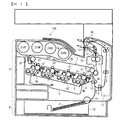
まず、本発明の実施形態に係る画像形成装置の全体構成について説明する。図1に示す画像形成装置100はカラーレーザープリンタであり、画像形成部Aと、給紙部Bと、一対の排紙ローラ対13と、排紙トレイ14と、定着装置20と、カール矯正装置21等を有している。画像形成部Aは、後述する4つの作像部4Y,4M,4C,4Kと、露光装置9と、転写装置3等を含んでいる。以下詳細に説明する。
Hereinafter, a powder amount detecting device according to an embodiment of the present invention and an image forming device having the powder amount detecting device will be described with reference to the drawings.
(Image forming device)
First, the overall configuration of the image forming apparatus according to the embodiment of the present invention will be described. The
画像形成装置100の画像形成装置本体の中央には、4つの作像部4Y,4M,4C,4Kが設けられている。各作像部4Y,4M,4C,4Kは、カラー画像の色分解成分に対応するイエロー(Y)、マゼンタ(M)、シアン(C)、ブラック(K)の異なる色の現像剤を収容している以外は同様の構成となっている。
Four
具体的に、各作像部4Y,4M,4C,4Kは、潜像担持体としてのドラム状の感光体5と、感光体5の表面を帯電させる帯電装置6と、感光体5の表面に粉体としてのトナーを供給する現像装置7と、感光体5の表面をクリーニングするクリーニング装置8と、を含む。
Specifically, each
なお、図1においては、ブラックの作像部4Kが備える感光体5、帯電装置6、現像装置7、クリーニング装置8のみに符号を付しており、その他の作像部4Y,4M,4Cは、ブラックの作像部4Kと同様な構成なので、その符号を省略している。
In FIG. 1, only the
各作像部4Y,4M,4C,4Kの下方には、感光体5の表面を露光する露光装置9が配設されている。露光装置9は、レーザー光源、ポリゴンミラー、f−θレンズ、複数の反射ミラー等を有し、画像データに基づいて各感光体5の表面へレーザー光を照射し各感光体5の表面に静電潜像を形成するようになっている。
Below each
また、各作像部4Y,4M,4C,4Kの上方には、転写装置3が配設されている。転写装置3は、中間転写体としての中間転写ベルト30と、一次転写手段としての4つの一次転写ローラ31と、二次転写手段としての二次転写ローラ36と、二次転写バックアップローラ32と、クリーニングバックアップローラ33と、テンションローラ34と、ベルトクリーニング装置35と、を備える。
Further, a transfer device 3 is arranged above each
中間転写ベルト30は、無端状のベルトであり、二次転写バックアップローラ32、クリーニングバックアップローラ33およびテンションローラ34によって張架されている。ここでは、二次転写バックアップローラ32を回転駆動することによって、中間転写ベルト30は図の矢印で示す方向に周回走行(回転)するようになっている。
The
4つの一次転写ローラ31は、それぞれ、各感光体5との間で中間転写ベルト30を挟み込んで一次転写ニップを形成している。また、各一次転写ローラ31には、電源が接続されており、所定の直流電圧(DC)又は所定の交流電圧(AC)が各一次転写ローラ31に印加されるようになっている。
Each of the four
二次転写ローラ36は、二次転写バックアップローラ32との間で中間転写ベルト30を挟み込んで二次転写ニップを形成している。また、上記一次転写ローラ31と同様に、二次転写ローラ36にも電源が接続されており、所定の直流電圧(DC)又は交流電圧(AC)が二次転写ローラ36に印加されるようになっている。
The
ベルトクリーニング装置35は、中間転写ベルト30に当接するように配設されたクリーニングブラシとクリーニングブレードを有する。このベルトクリーニング装置35で回収された廃トナーは、廃トナー移送ホースを介して廃トナー収容器に収容される。
The
画像形成装置本体の上部には、ボトル収容部200が設けられており、ボトル収容部200には、補給用のトナーを収容する粉体容器としての4つのトナーボトル210Y,210M,210C,210Kが交換可能に装着されている。各トナーボトル210Y,210M,210C,210Kと上記各現像装置7との間に設けた補給路を介して、各トナーボトル210Y,210M,210C,210Kから各現像装置7に粉体としてのトナーが補給される。各トナーボトル210Y,210M,210C,210Kの出口部分には、図2〜図5で後述する粉体量検知装置としてのトナー量検知装置が配設されている。
A
一方、画像形成装置本体の下部には、給紙部Bを備えている。給紙部Bは、シート状体(記録媒体)としての記録媒体Pを収容した給紙トレイ10や、給紙トレイ10から記録媒体Pを搬出する給紙ローラ11等を有している。
On the other hand, a paper feeding unit B is provided at the lower part of the image forming apparatus main body. The paper feed unit B includes a
なお、記録媒体Pには、普通紙以外に、厚紙、はがき、封筒、薄紙、塗工紙(コート紙やアート紙等)、トレーシングペーパ、OHPシート等が含まれる。また、手差し給紙機構を備えていてもよい。本実施形態において「厚紙」とは、坪量が160g/m2以上の紙を言うものとする。 In addition to plain paper, the recording medium P includes thick paper, postcards, envelopes, thin paper, coated paper (coated paper, art paper, etc.), tracing paper, OHP sheets, and the like. Further, a manual paper feed mechanism may be provided. In the present embodiment, "thick paper" means paper having a basis weight of 160 g / m2 or more.
画像形成装置本体内には、記録媒体Pを給紙トレイ10から二次転写ニップを通過させて装置外へ排出するための搬送路Rが配設されている。当該搬送路Rにおいて、二次転写ローラ36の位置よりも記録媒体搬送方向上流側には、搬送タイミングを計って記録媒体Pを二次転写ニップへ搬送するタイミングローラとしての一対のレジストローラ12が配設されている。
A transport path R for passing the recording medium P from the paper feed tray 10 through the secondary transfer nip and discharging it to the outside of the apparatus is provided in the image forming apparatus main body. In the transport path R, a pair of
また、二次転写ローラ36の位置よりも記録媒体搬送方向下流側には、未定着トナー画像を担持させた記録媒体Pを加圧・加熱してトナー画像を記録媒体Pに定着させる定着装置20が配設されている。さらに、定着装置20よりも搬送路Rの記録媒体搬送方向下流側には、記録媒体Pを装置外へ排出するための一対の排紙ローラ対13が設けられている。また、画像形成装置本体の上面部には、装置外に排出された記録媒体Pをストックするための排紙トレイ14が設けられている。
Further, a
(画像形成装置の基本的動作)
次に、本発明の実施形態に係る画像形成装置100の基本的動作について説明する。まず、作像動作が開始されると、各作像部4Y,4M,4C,4Kにおける各感光体5が図の時計回りに回転駆動され、各感光体5の表面が帯電装置6によって所定の極性に一様に帯電される。帯電された各感光体5の表面には、露光装置9からレーザー光がそれぞれ照射されて、各感光体5の表面に静電潜像が形成される。
(Basic operation of image forming apparatus)
Next, the basic operation of the
このとき、各感光体5に露光する画像情報は所望のフルカラー画像をイエロー、マゼンタ、シアンおよびブラックの色情報に分解した単色の画像情報である。このように各感光体5上に形成された静電潜像に、各現像装置7によってトナーが供給されることにより、静電潜像は画像として顕像化(可視像化)される。
At this time, the image information to be exposed to each
また、作像動作が開始されると、二次転写バックアップローラ32が図の反時計回りに回転駆動し、中間転写ベルト30を図の矢印で示す方向に周回走行させる。また、各一次転写ローラ31に、トナーの帯電極性と逆極性の定電圧又は定電流制御された電圧が印加されることによって、各一次転写ローラ31と各感光体5との間の一次転写ニップにおいて転写電界が形成される。
When the image-drawing operation is started, the secondary
その後、各感光体5の回転に伴い、感光体5上の各色の画像が一次転写ニップに達したときに、上記一次転写ニップにおいて形成された転写電界によって、各感光体5上の画像が中間転写ベルト30上に順次重ね合わせて転写される。
After that, as the rotation of each
このようにして、中間転写ベルト30の表面にフルカラーの画像が担持される。また、中間転写ベルト30に転写しきれなかった各感光体5上のトナーは、クリーニング装置8によって除去される。そして、各感光体5の表面が除電装置によって除電され、表面電位が初期化される。
In this way, a full-color image is supported on the surface of the
プリンタの下部では、給紙ローラ11が回転駆動を開始し、給紙トレイ10から記録媒体Pが搬送路Rに送り出される。搬送路Rに送り出された記録媒体Pは、レジストローラ12によって搬送が一旦停止される。
At the lower part of the printer, the paper feed roller 11 starts rotational driving, and the recording medium P is sent out from the
その後、所定のタイミングでレジストローラ12の回転駆動を開始し、中間転写ベルト30上の画像が二次転写ニップに達するタイミングに合わせて、記録媒体Pを二次転写ニップへ搬送する。このとき、二次転写ローラ36には、中間転写ベルト30上の画像のトナー帯電極性と逆極性の転写電圧が印加されており、これにより、二次転写ニップに転写電界が形成されている。
After that, the rotational drive of the resist
そして、この転写電界によって、中間転写ベルト30上の画像が記録媒体P上に一括して転写される。また、このとき記録媒体Pに転写しきれなかった中間転写ベルト30上の残留トナーは、ベルトクリーニング装置35によって除去され、廃トナー収容器へと搬送される。
Then, the images on the
その後、記録媒体Pは定着装置20へと搬送され、定着装置20によって記録媒体P上の画像が当該記録媒体Pに定着される。定着装置20から搬送された記録媒体Pは、カール矯正装置21を通過して機外の排紙トレイ14上に排紙される。
After that, the recording medium P is conveyed to the fixing
以上の説明は、記録媒体P上にフルカラー画像を形成するときの画像形成動作であるが、4つの作像部4Y,4M,4C,4Kのいずれか1つを使用して単色画像を形成し、また2つ又は3つの作像部を使用して、2色又は3色の画像を形成することも可能である。
The above description is an image forming operation when forming a full-color image on the recording medium P, but a monochromatic image is formed by using any one of the four
(トナー量検知装置)
次に、前述したトナーボトル210内のトナー量を検知するトナー量検知装置について説明する。トナーボトル210は詳しくは図2に示すように円筒状に成形され、その内部にトナーTが収容されている。円筒状のトナーボトル210はその一端側に底部210aを有し、他端側に粉体供給口としての円形のトナー供給口210bを有する。
(Toner amount detection device)
Next, the toner amount detecting device for detecting the toner amount in the
このトナー供給口210bの軸線はトナーボトル210の軸線と同一であり、トナーボトル210は全体として回転対称形状である。またトナーボトル210の内周面には螺旋状のリブ又は溝部が形成され、ボトルの回転でトナーTをトナー供給口210b側に移動可能に構成している。
The axis of the
図2のトナーボトル210はその軸線を水平にして画像形成装置100のボトル収容部200に対してトナー供給口210bを先にして図2(a)で右向きで挿入されている。ボトル収容部200にはトナーボトル210をその軸線回りの一方向に間欠回転するための駆動装置が配設されている。この間欠回転と前記螺旋状のリブ又は溝部の作用によって、トナーボトル210内のトナーTが右方向、すなわちトナー供給口210b側に移動されるようになっている。
The
ボトル収容部200の奥側には、水平にセットされたトナーボトル210と同軸状に筒状のトナー搬送部212が水平に固定配置されている。このトナー搬送部212は、筒状ガイド部212aと、当該筒状ガイド部212aに回転可能に収容されて筒状ガイド部212aの先端部分まで延びた搬送スクリュ212bとを有する。筒状ガイド部212aの先端部分の上部壁は、軸線方向に所定長さで切り欠かれてトナー補給口212cとされている。
On the back side of the
トナー搬送部212の筒状ガイド部212aの外周面には内側電極216が配設されている。当該内側電極216は、シート状の導電性金属を円筒状に成形して筒状ガイド部212aの外周面に接着することで構成することができる。また当該内側電極216の半径方向外側に位置するようにして、トナーボトル210の外周に外側電極215が配設されている。
An
当該外側電極215もシート状の導電性金属を円筒状に成形して構成することができる。内側電極216と外側電極215は、トナーボトル210又はトナー供給口210bの軸線に対して平行とされ、したがって電極相互も同軸状で平行に配置されている。
The
図2に示すように、これら内側電極216と外側電極215に対して電極間電圧測定手段220が接続されている。この電極間電圧測定手段220は、内側電極216と外側電極215との間に電界をかけることにより、電極相互間に生じる静電容量を検知する検知手段として機能する。
As shown in FIG. 2, the inter-electrode voltage measuring means 220 is connected to the
また電極間電圧測定手段220は残量判断手段230に接続されている。この残量判断手段230は、内側電極216と外側電極215との間の静電容量の大きさから、内側電極216と外側電極215との間に存在するトナー量を検知する。静電容量の大きさとトナー量の関係は、実験等により予め求めておくことができる。
Further, the inter-electrode voltage measuring means 220 is connected to the remaining
外側電極215は、図2ではトナーボトル210の外周面の全周360°に亘って環状に連続して配設されているが、必ずしも環状に連続して配設する必要はない。外側電極215は、最低限、図3のように水平にセットされたトナーボトル210の底部付近に配設されていればよい。外側電極215が底部付近に配設されていれば、図3(b)のようにトナーTの残りが少なくなった状態でも、内側電極216との間の静電容量Cの大きさからトナー量を検知することができる。
In FIG. 2, the
一方、トナー補給口212cの部分には内側電極がないので、当該トナー補給口212cに対応する部分のみ部分的に切り欠いた外側電極形状にしてもよい。このような外側電極形状は図3で上向きに開口した断面C字形状となる。外側電極形状が周方向上方に長く延びているほど、トナー量の正確な減少推移を継続的に検知することができる。
On the other hand, since the
前述した外側電極215は、図4Aのように本体側に配設したり、或いは図4Bのようにトナーボトル側に配設したりすることができる。図4Aと図4Bとも、外側電極215は周方向に連続した円筒状である。
The above-mentioned
外側電極215を図4Aのように本体側に固定的に配設すると、トナーボトル210が外側電極でコストアップするのを回避することができる。また、トナーボトル210の交換に関わらず、外側電極215と内側電極216の間隔を常に一定に維持することができ、電極間隔の変動によるトナー量の検知誤差をなくすことができる。
When the
一方、図4Bのように外側電極215をトナーボトル側に配設すると、1)外側電極215をボトル周面に密着させることでトナー量の検知精度を高めることができる、2)ボトル収容部200のスペースをコンパクト化することができる、3)トナーボトル210の装着時におけるトナーボトル210回転位置の制限が無くなる、といった利点が得られる。
On the other hand, if the
また、画像形成装置内でのトナー飛散などで外側電極215表面が汚れてしまった場合でも、トナーボトル210の交換と共に外側電極215を交換することができる。外側電極215と電極間電圧測定手段220との接続は、トナーボトル210装着時に外側電極215が接触する例えば接触点220aで確保することができる。
Further, even when the surface of the
外側電極215の具体的な取り付け方は、トナーボトル210の外周面に貼り付けられる品番等の表示ラベルに外側電極215を一体的に設置する方法などが考えられる。外側電極215を表示ラベルに一体化することで外側電極215の取り付けの手間を省略することができる。
As a specific method of attaching the
(トナー量検知装置の作用)
トナーボトル210が図2(a)においてボトル収容部200に右向きに挿入・セットされると、ボトル収容部200の奥側に配置されたトナー搬送部212の筒状ガイド部212aが、トナーボトル210のトナー供給口210bに挿入される。この状態でトナーボトル210が間欠的に回転されると、トナー搬送部212のトナー補給口212cにトナーTが補給される。
(Action of toner amount detection device)
When the
すなわち、トナーボトル210内のトナーTは、トナーボトル210が回転することで周方向に巻き上げられながら、前述した螺旋状のリブ又は溝部の作用で図2(a)で右方向に徐々に移動される。そしてトナー供給口210bの付近で周方向に巻き上げられたトナーTが、トナー搬送部212の上部のトナー補給口212cから内側に落下する。トナーTが落下した位置には搬送スクリュ212bの先端部分が位置しており、当該トナーTは搬送スクリュ212bによって画像形成装置100の現像装置7へと搬送される。
That is, the toner T in the
トナーTがボトル外に搬送されるにつれて、ボトル内のトナーTの表面が低下し、それに対応して残量判断手段230がトナー量の低下を検知する。内側電極216は本体側のトナー搬送部212の先端表面に位置し、トナーボトル210をボトル収容部200に装着した際にトナーボトル210のトナー供給口210b内に挿入される。これにより、内側電極216と外側電極215との間にトナーTを挟み込む電極配置になる。この電極配置を取ることでトナー切れの直前まで正確にトナー量の検知を行うことができる。
As the toner T is conveyed out of the bottle, the surface of the toner T in the bottle is lowered, and the remaining amount determining means 230 detects the decrease in the amount of toner correspondingly. The
すなわち、図3(a)のようにトナー量が多い場合は電極間の静電容量Cが大きいため残量判断手段230でトナー量が多いと判断される。これに対して図3(b)のようにトナー量が少ない場合は電極間の静電容量Cも少ないため、残量判断手段230でトナー量が少ないと判断される。この際、外側電極215と内側電極216を共にトナーボトル210と同じ中心軸をとる同軸円筒状にすることで、トナー補給のためにトナーボトル210が回転することによる電極間のトナー量変動を無くすことができる。
That is, when the amount of toner is large as shown in FIG. 3A, the capacitance C between the electrodes is large, so that the remaining amount determining means 230 determines that the amount of toner is large. On the other hand, when the amount of toner is small as shown in FIG. 3B, the capacitance C between the electrodes is also small, so that the remaining amount determining means 230 determines that the amount of toner is small. At this time, by forming both the
トナーボトル210のトナー供給口210b付近には、トナー量がゼロになる直前までトナーTが常に滞留している。つまりトナー量が少なくなってきてトナーボトル210の底部210a側でトナーTがまったくなくなっても、図3(b)のようにトナー供給口210b付近の外側電極215と内側電極216との間には、トナー量がゼロになる直前まで必ずトナーTが存在している。
Toner T is always retained in the vicinity of the
したがって、トナー切れの直前まで正確にトナー量の検知を行うことができ、トナー量の誤検知によりトナーボトル210の交換時期が早過ぎたり遅過ぎたりするのを防止することができる。
Therefore, the toner amount can be accurately detected until just before the toner runs out, and it is possible to prevent the
図5は、軸線方向で長い円筒状の外側電極215をボトル収容部200の内壁に配設したものである。この外側電極215によってトナーボトル210の外周面の殆どすべてが覆われている。外側電極215以外は図2の構成と同じである。
FIG. 5 shows an axially long cylindrical
図5では外側電極215によってトナーボトル210の外周面の殆どすべてが覆われているため、トナーボトル210のトナー量が多い使用開始時からトナー切れに至るまで、トナー量の正確な減少推移を継続的に検知することができる。したがってボトル交換時期をより正確に把握することができる。この外側電極215は、図4Bと同じように、トナーボトル210の外周面に貼り付けられる品番等の表示ラベルに一体的に設置することも可能である。
In FIG. 5, since almost the outer peripheral surface of the
以上、本発明をその実施形態に基づいて具体的に説明したが、本発明は前記実施形態に限定されるものではなく、特許請求の範囲に記載の技術的思想の範囲内で種々変更可能であることは言うまでもない。例えば前記実施形態ではトナーボトル210の形状や外側電極215、内側電極216の形状を円筒状としたが、外側電極215と内側電極216を請求項1のように配設できれば必ずしもこれらを円筒状に限定する必要はなく、任意の形状を採用可能である。
Although the present invention has been specifically described above based on the embodiment, the present invention is not limited to the embodiment and can be variously modified within the scope of the technical idea described in the claims. Needless to say, there is. For example, in the above embodiment, the shape of the
3:転写装置 4Y,4M,4C,4K:作像部
5:感光体 6:帯電装置
7:現像装置 8:クリーニング装置
9:露光装置 10:給紙トレイ
11:給紙ローラ 12:レジストローラ
13:排紙ローラ対 14:排紙トレイ
20:定着装置 21:カール矯正装置
30:中間転写ベルト 31:一次転写ローラ
32:二次転写バックアップローラ 33:クリーニングバックアップローラ
34:テンションローラ 35:ベルトクリーニング装置
36:二次転写ローラ 100:画像形成装置
200:ボトル収容部 210Y,210M,210C,210K:トナーボトル
210a:ボトル底部 210b:トナー供給口
212:トナー搬送部 212a:筒状ガイド部
212b:搬送スクリュ 212c:トナー補給口
215:外側電極 216:内側電極
220:電極間電圧測定手段 220a:接触点
230:残量判断手段 A:画像形成部
B:給紙部 C:静電容量
P:記録媒体 R:搬送路
T:トナー
3:
Claims (8)
前記粉体容器の外側に配設される外側電極と、
前記外側電極と対向するように前記粉体容器の粉体供給口の内側に配設される内側電極と、
前記外側電極と前記内側電極との間に電界をかけることにより電極相互間に生じる静電容量を検知する検知手段とを有する粉体量検知装置において、
前記内側電極が前記画像形成装置側に固定的に配設され、前記画像形成装置に前記粉体容器を装着することにより前記内側電極が前記粉体供給口に挿入されることを特徴とする粉体量検知装置。 A powder amount detection device that detects the amount of powder in a powder container that is replaceably mounted on an image forming device.
An outer electrode arranged on the outside of the powder container and
An inner electrode arranged inside the powder supply port of the powder container so as to face the outer electrode,
In powder amount detecting device that having a detecting means for detecting an electrostatic capacitance generated between the electrodes by applying an electric field between the inner electrode and the outer electrode,
The powder is characterized in that the inner electrode is fixedly arranged on the image forming apparatus side, and the inner electrode is inserted into the powder supply port by mounting the powder container on the image forming apparatus. Body mass detection device.
Priority Applications (2)
| Application Number | Priority Date | Filing Date | Title |
|---|---|---|---|
| JP2017110794A JP6889859B2 (en) | 2017-06-05 | 2017-06-05 | Powder amount detection device and image forming device |
| US15/996,593 US10429770B2 (en) | 2017-06-05 | 2018-06-04 | Powder-amount detection device and image forming apparatus incorporating same |
Applications Claiming Priority (1)
| Application Number | Priority Date | Filing Date | Title |
|---|---|---|---|
| JP2017110794A JP6889859B2 (en) | 2017-06-05 | 2017-06-05 | Powder amount detection device and image forming device |
Publications (2)
| Publication Number | Publication Date |
|---|---|
| JP2018205532A JP2018205532A (en) | 2018-12-27 |
| JP6889859B2 true JP6889859B2 (en) | 2021-06-18 |
Family
ID=64458804
Family Applications (1)
| Application Number | Title | Priority Date | Filing Date |
|---|---|---|---|
| JP2017110794A Active JP6889859B2 (en) | 2017-06-05 | 2017-06-05 | Powder amount detection device and image forming device |
Country Status (2)
| Country | Link |
|---|---|
| US (1) | US10429770B2 (en) |
| JP (1) | JP6889859B2 (en) |
Families Citing this family (3)
| Publication number | Priority date | Publication date | Assignee | Title |
|---|---|---|---|---|
| JP6922412B2 (en) * | 2017-05-24 | 2021-08-18 | 株式会社リコー | Powder amount detection device and image forming device |
| JP7253146B2 (en) * | 2019-07-31 | 2023-04-06 | 株式会社リコー | Powder amount detection device, powder replenishment device and image forming device |
| JP7360613B2 (en) * | 2019-08-22 | 2023-10-13 | 株式会社リコー | Toner storage device and image forming device |
Family Cites Families (13)
| Publication number | Priority date | Publication date | Assignee | Title |
|---|---|---|---|---|
| JPH08211755A (en) | 1994-11-15 | 1996-08-20 | Ricoh Co Ltd | Image forming device |
| JPH08320622A (en) | 1995-03-22 | 1996-12-03 | Ricoh Co Ltd | Intermediate transfer medium and image forming apparatus |
| US5774775A (en) | 1995-03-31 | 1998-06-30 | Ricoh Company, Ltd. | Electrophotograhic image forming method using an intermediate image transfer element |
| JP2004286793A (en) | 2003-03-19 | 2004-10-14 | Konica Minolta Holdings Inc | Image forming apparatus |
| JP2004286792A (en) | 2003-03-19 | 2004-10-14 | Konica Minolta Holdings Inc | Image forming apparatus |
| JP4684631B2 (en) * | 2004-11-22 | 2011-05-18 | キヤノン株式会社 | Image forming apparatus |
| CN2821622Y (en) * | 2005-07-13 | 2006-09-27 | 珠海天威飞马打印耗材有限公司 | Carbon powder cartridge of laser printer |
| JP2009116120A (en) | 2007-11-07 | 2009-05-28 | Ricoh Co Ltd | Toner supply device and image forming apparatus |
| JP5777388B2 (en) * | 2011-04-19 | 2015-09-09 | キヤノン株式会社 | Image forming apparatus |
| JP6090668B2 (en) * | 2013-06-03 | 2017-03-08 | 株式会社リコー | Powder replenishing apparatus and image forming apparatus |
| JP6444142B2 (en) * | 2014-11-11 | 2018-12-26 | キヤノン株式会社 | Image forming apparatus |
| JP2016206616A (en) * | 2015-04-28 | 2016-12-08 | 京セラドキュメントソリューションズ株式会社 | Image formation device |
| US10053317B2 (en) | 2016-08-08 | 2018-08-21 | Ricoh Company, Ltd. | Contact-and-separation system, image forming apparatus, and contact-and-separation method |
-
2017
- 2017-06-05 JP JP2017110794A patent/JP6889859B2/en active Active
-
2018
- 2018-06-04 US US15/996,593 patent/US10429770B2/en not_active Expired - Fee Related
Also Published As
| Publication number | Publication date |
|---|---|
| US20180348673A1 (en) | 2018-12-06 |
| US10429770B2 (en) | 2019-10-01 |
| JP2018205532A (en) | 2018-12-27 |
Similar Documents
| Publication | Publication Date | Title |
|---|---|---|
| JP6922412B2 (en) | Powder amount detection device and image forming device | |
| JP5335543B2 (en) | Image forming apparatus | |
| JP2011186038A (en) | Image forming apparatus and toner supply method | |
| US11086265B2 (en) | Image forming apparatus | |
| US10331059B2 (en) | Developing device and image forming apparatus having a toner concentration detector and a retaining member that retains the developer in the toner concentration detecting region | |
| JP6889859B2 (en) | Powder amount detection device and image forming device | |
| JP6015011B2 (en) | Image forming apparatus | |
| US11143980B2 (en) | Image forming apparatus | |
| JP5656109B2 (en) | Toner supply device and image forming apparatus | |
| JP2012128323A (en) | Image forming apparatus | |
| US11150574B2 (en) | Image forming apparatus | |
| JP6008186B2 (en) | Developer supply device and image forming apparatus | |
| JP2012194493A (en) | Image forming apparatus | |
| JP6819647B2 (en) | Image forming device | |
| JP7468065B2 (en) | Powder conveying device and image forming device | |
| US12481238B2 (en) | Image forming apparatus | |
| JP2007240607A (en) | Image forming apparatus and process cartridge | |
| JP2016014788A (en) | Powder container and image forming apparatus | |
| US20250102976A1 (en) | Fixing device and image forming apparatus | |
| JP5535004B2 (en) | Image forming apparatus | |
| JP2013044774A (en) | Image forming apparatus | |
| US11042112B2 (en) | Image formation apparatus | |
| JP2023100337A (en) | Toner charging state determination method, image forming apparatus | |
| JP2008026521A (en) | Image forming apparatus | |
| JP2022182147A (en) | image forming device |
Legal Events
| Date | Code | Title | Description |
|---|---|---|---|
| A621 | Written request for application examination |
Free format text: JAPANESE INTERMEDIATE CODE: A621 Effective date: 20200226 |
|
| A977 | Report on retrieval |
Free format text: JAPANESE INTERMEDIATE CODE: A971007 Effective date: 20201214 |
|
| A131 | Notification of reasons for refusal |
Free format text: JAPANESE INTERMEDIATE CODE: A131 Effective date: 20201225 |
|
| A521 | Request for written amendment filed |
Free format text: JAPANESE INTERMEDIATE CODE: A523 Effective date: 20210218 |
|
| TRDD | Decision of grant or rejection written | ||
| A01 | Written decision to grant a patent or to grant a registration (utility model) |
Free format text: JAPANESE INTERMEDIATE CODE: A01 Effective date: 20210423 |
|
| A61 | First payment of annual fees (during grant procedure) |
Free format text: JAPANESE INTERMEDIATE CODE: A61 Effective date: 20210506 |
|
| R151 | Written notification of patent or utility model registration |
Ref document number: 6889859 Country of ref document: JP Free format text: JAPANESE INTERMEDIATE CODE: R151 |