JP6889840B2 - connector - Google Patents
connector Download PDFInfo
- Publication number
- JP6889840B2 JP6889840B2 JP2017215640A JP2017215640A JP6889840B2 JP 6889840 B2 JP6889840 B2 JP 6889840B2 JP 2017215640 A JP2017215640 A JP 2017215640A JP 2017215640 A JP2017215640 A JP 2017215640A JP 6889840 B2 JP6889840 B2 JP 6889840B2
- Authority
- JP
- Japan
- Prior art keywords
- housing
- mating
- electric wire
- inner housing
- outer housing
- Prior art date
- Legal status (The legal status is an assumption and is not a legal conclusion. Google has not performed a legal analysis and makes no representation as to the accuracy of the status listed.)
- Active
Links
Images

Classifications
-
- H—ELECTRICITY
- H01—ELECTRIC ELEMENTS
- H01R—ELECTRICALLY-CONDUCTIVE CONNECTIONS; STRUCTURAL ASSOCIATIONS OF A PLURALITY OF MUTUALLY-INSULATED ELECTRICAL CONNECTING ELEMENTS; COUPLING DEVICES; CURRENT COLLECTORS
- H01R13/00—Details of coupling devices of the kinds covered by groups H01R12/70 or H01R24/00 - H01R33/00
- H01R13/46—Bases; Cases
- H01R13/533—Bases, cases made for use in extreme conditions, e.g. high temperature, radiation, vibration, corrosive environment, pressure
-
- H—ELECTRICITY
- H01—ELECTRIC ELEMENTS
- H01R—ELECTRICALLY-CONDUCTIVE CONNECTIONS; STRUCTURAL ASSOCIATIONS OF A PLURALITY OF MUTUALLY-INSULATED ELECTRICAL CONNECTING ELEMENTS; COUPLING DEVICES; CURRENT COLLECTORS
- H01R13/00—Details of coupling devices of the kinds covered by groups H01R12/70 or H01R24/00 - H01R33/00
- H01R13/46—Bases; Cases
- H01R13/516—Means for holding or embracing insulating body, e.g. casing, hoods
-
- H—ELECTRICITY
- H01—ELECTRIC ELEMENTS
- H01R—ELECTRICALLY-CONDUCTIVE CONNECTIONS; STRUCTURAL ASSOCIATIONS OF A PLURALITY OF MUTUALLY-INSULATED ELECTRICAL CONNECTING ELEMENTS; COUPLING DEVICES; CURRENT COLLECTORS
- H01R13/00—Details of coupling devices of the kinds covered by groups H01R12/70 or H01R24/00 - H01R33/00
- H01R13/46—Bases; Cases
- H01R13/502—Bases; Cases composed of different pieces
- H01R13/506—Bases; Cases composed of different pieces assembled by snap action of the parts
Landscapes
- Connector Housings Or Holding Contact Members (AREA)
- Details Of Connecting Devices For Male And Female Coupling (AREA)
Description
本明細書に開示された技術は、コネクタに関する。 The techniques disclosed herein relate to connectors.
従来、雄ハウジングと雌ハウジングとを備えて車両等に使用されるコネクタとして、例えば特許文献1のものが知られている。このコネクタの第1ハウジングは、キャビティが設けられたインナハウジングと、筒型嵌合部が設けられたアウタハウジングとを備えて構成され、相手側端子の設けられた第2ハウジングに嵌合されるようになっている。
Conventionally, as a connector having a male housing and a female housing and used for a vehicle or the like, for example, the one of
アウタハウジングは、インナハウジングに対して筒型嵌合部を後方から被せるようにして組み付けられる。アウタハウジングの後端面には保持孔が設けられ、この保持孔から雌端子金具がインナハウジングのキャビティに挿入される。雌端子金具の後端には電線が接続され、電線の外周にはゴム栓が外嵌されている。ゴム栓の本体部はキャビティの後端側の内周に液密状に密着され、当該ゴム栓の後端に設けられた防振部は保持孔内に嵌入される。 The outer housing is assembled so that the inner housing is covered with the tubular fitting portion from the rear. A holding hole is provided on the rear end surface of the outer housing, and the female terminal fitting is inserted into the cavity of the inner housing through the holding hole. An electric wire is connected to the rear end of the female terminal fitting, and a rubber stopper is fitted on the outer circumference of the electric wire. The main body of the rubber stopper is in close contact with the inner circumference on the rear end side of the cavity in a liquidtight manner, and the vibration isolator provided at the rear end of the rubber stopper is fitted into the holding hole.
インナハウジングの後端部の外周面とアウタハウジングの筒型嵌合部の後面壁の内周面との間には、アウタハウジングのインナハウジングに対する僅かな相対変位を許容するクリアランスが確保されている。そして、アウタハウジングから後方へ導出されている電線が軸線と交差する方向に振動した場合には、その振動エネルギーの一部がアウタハウジングを変位させるための運動エネルギーとして吸収される。これにより、電線から雌端子金具に伝達される振動が減衰され、雌端子金具と相手側端子金具との接点における微摺動摩耗を生じることが防止されるようになっている。 A clearance is secured between the outer peripheral surface of the rear end of the inner housing and the inner peripheral surface of the rear wall of the tubular fitting portion of the outer housing to allow a slight relative displacement of the outer housing with respect to the inner housing. .. Then, when the electric wire led out from the outer housing to the rear vibrates in the direction intersecting the axis, a part of the vibration energy is absorbed as kinetic energy for displacing the outer housing. As a result, the vibration transmitted from the electric wire to the female terminal fitting is attenuated, and it is possible to prevent slight sliding wear at the contact point between the female terminal fitting and the mating terminal fitting.
しかしこの構成では、クリアランスにおいて変位しても電線の振動エネルギーを吸収しきれない場合には、アウタハウジングはインナハウジングに当接し、インナハウジングに運動エネルギーを伝達することになる。この結果、インナハウジングが振動し、その内部に収容された雌端子金具と相手側端子金具との接点において微摺動摩耗が生じてしまう。 However, in this configuration, if the vibration energy of the electric wire cannot be completely absorbed even if the electric wire is displaced in the clearance, the outer housing abuts on the inner housing and the kinetic energy is transmitted to the inner housing. As a result, the inner housing vibrates, and slight sliding wear occurs at the contact point between the female terminal fitting housed therein and the mating terminal fitting.
本明細書に開示された技術に係るコネクタは、電線が外部に引き出されて相手側ハウジングに嵌合するインナハウジングと、前記相手側ハウジングに当接可能とされた相手側当接部を有する振動伝達部材と、を備えるコネクタであって、前記振動伝達部材は前記電線が固定される電線固定部を有し、前記電線固定部からの振動を前記相手側当接部から前記相手側ハウジングに伝達可能とされ、前記インナハウジングは前記振動伝達部材に対して相対移動が許容されている。 The connector according to the technique disclosed in the present specification has an inner housing in which an electric wire is pulled out to the outside and fits into the mating housing, and a vibration having a mating contact portion capable of contacting the mating housing. A connector including a transmission member, wherein the vibration transmission member has an electric wire fixing portion to which the electric wire is fixed, and the vibration from the electric wire fixing portion is transmitted from the mating end contact portion to the mating housing. It is possible, and the inner housing is allowed to move relative to the vibration transmitting member.
この構成によれば、電線が振動した場合、その振動は電線固定部から振動伝達部材を介して相手側ハウジングに伝達されるから、電線からインナハウジングに伝わる振動を減少させることができる。電線からインナハウジングに振動が伝わったとしても、インナハウジングは振動伝達部材に対して相対移動が許容されているから、電線から伝わる振動を減衰させることができる。これにより、例えばインナハウジングと相手側ハウジングにそれぞれ端子を収容し互いに接触させた場合、インナハウジングの相対移動によって減衰させた振動を各端子同士の接圧によって抑え込めるから、各端子同士の摺動による摩耗を抑制することができる。 According to this configuration, when the electric wire vibrates, the vibration is transmitted from the electric wire fixing portion to the mating housing via the vibration transmission member, so that the vibration transmitted from the electric wire to the inner housing can be reduced. Even if the vibration is transmitted from the electric wire to the inner housing, the inner housing is allowed to move relative to the vibration transmitting member, so that the vibration transmitted from the electric wire can be attenuated. As a result, for example, when terminals are housed in the inner housing and the mating housing and brought into contact with each other, the vibration attenuated by the relative movement of the inner housing can be suppressed by the contact pressure between the terminals, so that the terminals can slide with each other. It is possible to suppress the wear caused by.
本明細書に開示された技術に係る実施態様として、次の構成が好ましい。
(1)前記インナハウジングは前記振動伝達部材のロック突起が係止可能なロック片を備え、前記ロック突起と前記ロック片との間には前記インナハウジングの前記振動伝達部材に対する相対移動を許容するクリアランスが設けられている。
As an embodiment according to the technique disclosed in the present specification, the following configuration is preferable.
(1) The inner housing includes a lock piece to which the lock protrusion of the vibration transmission member can be locked, and allows the inner housing to move relative to the vibration transmission member between the lock protrusion and the lock piece. There is a clearance.
この構成によれば、相手側ハウジングに嵌合しない状態においてインナハウジングのロック片を振動伝達部材のロック突起に係止させておくことで、これらを一体的に取り扱うことが可能になる。また、ロック突起とロック片との間にクリアランスを設けているから、インナハウジングの相対移動を確保しつつインナハウジングと振動伝達部材を一体的に取り扱うことができる。 According to this configuration, by locking the lock piece of the inner housing to the lock protrusion of the vibration transmission member in a state where it is not fitted to the mating housing, it is possible to handle them integrally. Further, since the clearance is provided between the lock protrusion and the lock piece, the inner housing and the vibration transmission member can be handled integrally while ensuring the relative movement of the inner housing.
(2)前記振動伝達部材は、前記相手側当接部を有し前記インナハウジングを覆うアウタハウジングと、前記電線固定部を有し前記アウタハウジングおよび前記電線を覆うカバー部材と、を備える。 (2) The vibration transmission member includes an outer housing having the mating portion and covering the inner housing, and a cover member having the electric wire fixing portion and covering the outer housing and the electric wire.
この構成によれば、カバー部材によって、インナハウジング、アウタハウジングおよび電線を覆い、外部から保護することができる。 According to this configuration, the cover member can cover the inner housing, the outer housing, and the electric wire to protect them from the outside.
(3)前記アウタハウジングは、前記相手側ハウジングに対して第一クリアランスを隔てて対向するとともに、前記インナハウジングに対して前記第一クリアランスよりも大きい第二クリアランスを隔てて対向する。 (3) The outer housing faces the mating housing with a first clearance and faces the inner housing with a second clearance larger than the first clearance.
この構成によれば、アウタハウジングが相手側ハウジングに当接しても(すなわち第一クリアランスの寸法分だけ移動しても)、その移動距離は第二クリアランスの寸法より小さいから、アウタハウジングがインナハウジングに当接することはなく、電線からの振動をアウタハウジングからインナハウジングに直接伝えることがない。 According to this configuration, even if the outer housing abuts on the mating housing (that is, even if it moves by the dimension of the first clearance), the moving distance is smaller than the dimension of the second clearance, so that the outer housing is the inner housing. The vibration from the electric wire is not directly transmitted from the outer housing to the inner housing.
本明細書に開示された技術に係るコネクタによれば、電線の振動による端子の微摺動摩擦を防ぐことができる。 According to the connector according to the technique disclosed in the present specification, it is possible to prevent fine sliding friction of the terminal due to vibration of the electric wire.
<実施形態>
本明細書に開示された技術に係る一実施形態を、図1から図11によって説明する。
<Embodiment>
An embodiment according to the technique disclosed herein will be described with reference to FIGS. 1 to 11.
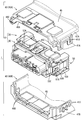
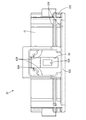
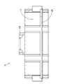
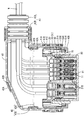
本実施形態の雌コネクタ1(コネクタの一例)は、相手側コネクタのハウジング(以下「相手側ハウジング90」という)に嵌合されることで相手側コネクタに電気的に接続され、振動が多く発生する振動環境下(例えば車両のタイヤ周辺等)において使用される。雌コネクタ1は、図1及び図2に示すように全体としてやや扁平な略直方体形状をなす雌ハウジング10と、雌ハウジング10を覆うカバー部材40とを備えている。なお以下においては、雌ハウジング10における相手側ハウジング90との嵌合側を前方、図1における上方を上方として説明する。
The female connector 1 (an example of a connector) of the present embodiment is electrically connected to the mating connector by being fitted into the housing of the mating connector (hereinafter referred to as “the
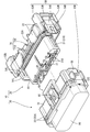
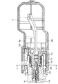
雌ハウジング10は、図3に示すように、インナハウジング20と、インナハウジング20の外周側に配されるアウタハウジング30と、により構成されている。インナハウジング20とアウタハウジング30は、図2に示すように、インナハウジング20およびアウタハウジング30に設けられた第一ロック部50によって互いに組み付いた状態とされている。
As shown in FIG. 3, the
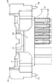
インナハウジング20は、図4および図5に示すように、後壁部23と、後壁部23の中央部に配されて横長の扁平形状をなす端子収容部21と、端子収容部21の外周側に配されてアウタハウジング30の外周側に嵌合する後方フード部22と、を備えている。
As shown in FIGS. 4 and 5, the
端子収容部21は、後壁部23から前方に延びる形状をなしている。端子収容部21のうち、後半部分は略直方体形状のベース部21Aとされ、前半部分は前後に長い複数の収容突部21Bとされている。端子収容部21には、図8に示すように、前方に開口する複数のキャビティ21Dが、各収容突部21Bの前端から後壁部23の後端に亘って前後方向に貫通して設けられている。各キャビティ21Dには、雌端子11が後方開口から挿入されている。雌端子11の後端に接続された電線Wは、キャビティ21Dの後方開口からインナハウジング20の外部に引き出されている。
The terminal
雌端子11は、図8に示すように、前側に角筒部を備え、角筒部内には片持ち形状のばね片11Aが角筒部の天井内壁11Bに対向して配されている。これにより、相手側ハウジング90の相手側端子91が角筒部内に挿入された際に、相手側端子91に対して所定の接圧をもって接続されるようになっている。
As shown in FIG. 8, the
後方フード部22は、図5に示すように、後壁部23の周縁から前方に延びる形態とされており、端子収容部21の上側に設けられた第二ロック部受け入れ溝22Aと、端子収容部21の左右両側に設けられたロック突起受け入れ溝22Bとを備えている。第二ロック部受け入れ溝22Aは、後方フード部22の上側中央部とこれに連なる後壁部23とが前後方向に切り欠かれた形態とされている。一方、ロック突起受け入れ溝22Bは、後方フード部22の左右両側が前後方向に切り欠かれた形態とされている。すなわち、後方フード部22は、後壁部23の上縁の中央部分を除く部分、左右側縁の上下両端部分、および下縁全体からベース部21Aを包囲するように前方に延びている。後方フード部22とベース部21Aの間には嵌合空間S1が形成され、後述するように、アウタハウジング30および相手側ハウジング90を受け入れ可能となっている。
As shown in FIG. 5, the
ベース部21Aの後端には、図3に示すように、弾性材からなるシールリング70が嵌められている。シールリング70はベース部21Aに対応して四角が丸みを帯びた角環形状をなし、ベース部21Aの全周に液密に接触している。シールリング70の外周面には3条のリップ71A,71Bがそれぞれ周方向に連続して設けられている。
As shown in FIG. 3, a
複数の収容突部21Bには、図3に示すように、横長の扁平な角筒形状のフロントキャップ80が一括して被せられている。フロントキャップ80の前面側に設けられた閉鎖面には、複数の相手側端子挿通孔が前後に貫通して形成されている。フロントキャップ80は、図8に示すように、後端近傍の内周面をベース部21Aの外周面に接触させ、後端をシールリング70の前端に対向させて配置されている。
As shown in FIG. 3, the plurality of accommodating
端子収容部21の右側には、図3および図5に示すように、第一ロック部50を構成する右側ロック片51Rおよび上下一対の右側支持部52Rが設けられるとともに、端子収容部21の左側には、第一ロック部50を構成する左側ロック片51Lおよび上下一対の左側支持部52Lが設けられている。右側ロック片51Rおよび右側支持部52Rと左側ロック片51Lおよび左側支持部52Lとは、端子収容部21を中心として左右対称の位置に設けられ、その構成は端子収容部21に関して左右対称の形状となっている。したがって、以下においては右側ロック片51Rおよび右側支持部52Rのみを代表して説明し、左側ロック片51Lおよび左側支持部52Lの説明は省略し、右側ロック片51Rおよび右側支持部52Rの符号のうちアルファベットのRをLに代えて図示のみするものとする。また、以下においては右側ロック片51Rと左側ロック片51Lをまとめて第一ロック片51R,51Lということがある。
As shown in FIGS. 3 and 5, a
上下一対の右側支持部52Rは、図4および図5に示すように、後方フード部22から側方に張り出した形状とされ、ロック突起受け入れ溝22Bを構成する上下一対の側壁に連なって形成されている。右側ロック片51Rは、上下一対の右側支持部52Rの間に配された平坦な帯形状の小片であり、端子収容部21の側壁に対して平行に延びている。右側ロック片51Rは、その上縁の中央よりも後方寄りにおいて上側の右側支持部52Rに支持されるとともに、その下縁の中央よりも後方寄りの位置において下側の右側支持部52Rに支持された片持ち形状をなし、その前端および後端が左右に移動可能とされている。右側ロック片51Rの後端はやや右方に突出しており、作業者が右側ロック片51Rを解除するための右側解除操作部53Rとなっている。右側ロック片51Rの前側には、左右に貫通する右側保持孔54Rが設けられている。
As shown in FIGS. 4 and 5, the pair of upper and lower
アウタハウジング30は、図3に示すように、インナハウジング20の端子収容部21の外周側に配置される略角筒形状の前方フード部31と、前方フード部31の外側面の一部が外側方に突出した形状の台座部55と、第一ロック部50を構成する右側ロック突起55Rおよび左側ロック突起55Lと、連結受け部32と、第二ロック部60と、を備えている。
As shown in FIG. 3, the
右側ロック突起55Rは、台座部55から右方に突出した形状とされ、アウタハウジング30がインナハウジング20の外周に取り付けられた場合にインナハウジング20の右側保持孔54Rに嵌まり込むことで右側ロック片51Rに係止可能な位置に設けられている。左側ロック突起55Lはアウタハウジング30の台座部55から左方に突出した形状とされ、前方フード部31を中心として右側ロック突起55Rと左右対称の位置に設けられている。
The
アウタハウジング30がインナハウジング20の外周に取り付けられた状態においては、図2および図10に示すように、第一ロック部50は右側ロック突起55Rが右側ロック片51Rの右側保持孔54Rに嵌まり込むことでロックされている。
When the
連結受け部32は、後述するカバー部材40をアウタハウジング30に連結するために設けられている。連結受け部32は、図3、図6、および図7に示すように、前後一対の上面突条部32Aと、下面突条部32Bと、突き当て受部32Cと、により構成されている。
The
上面突条部32Aは,前方フード部31の上面前端から上方に突出し、左右に延びている。下面突条部32Bは、前方フード部31の下面前端近傍から下方に突出し、左右に延びている。突き当て受部32Cは、図3に示すように、前方フード部31の外側面、台座部55の上端、および前後一対の上面側条部32Aの右端部によって囲まれた、前面透視で略直角三角形状をなす凹部である。
The upper
第二ロック部60は、前方フード部31の上面側に設けられ、図6に示すように、収容凹部62Aと、一対の収容壁部62Bと、触手規制部62Cと、上面側ロック片63により構成されている。
The
収容凹部62Aは、前方フード部31を上下に貫通し前方に開口している。一対の収容壁部62Bは、収容凹部62Aの両側および後端を囲うように上面視で門形状に設けられて収容凹部62Aの内壁を構成している。触手規制部62Cは、収容壁部62Bの前端開口を塞ぐように架け渡された形状に形成され、図3に示すように、前面視で門形状をなしている。
The
上面側ロック片63は、収容凹部62Aの後端を基端とし、前端側に向かって延びる片持ち状をなしている。上面側ロック片63の略中央部には、貫通孔63Aが上下に貫通して設けられている。
The upper surface
カバー部材40は、図1および図2に示すように、上側カバー40Aと、下側カバー40Bと、電線管43Aとによって構成され、これらが互いに組み付けられることにより、やや扁平な角筒の後端を一側方に延出させた形状の中空体をなしている。なお以下においては、上側カバー40Aと下側カバー40Bとが互いに組み付けられることで形成される前側および後側の開口のうち後側の開口およびその近傍を後側開口部43Bという。
As shown in FIGS. 1 and 2, the
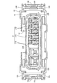
カバー部材40は、図10に示すように、ずれ止め部42と、カバーロック部41と、図1に示すように、アウタハウジング30に連結されるための連結部46と、電線固定部43と、を備えている。
As shown in FIG. 10, the
ずれ止め部42は、図10に示すように、上側カバー40Aの側壁部47Aの外面側および内面側から下方に延出して設けられたずれ止め片42Aと、下側カバー40Bの側壁部47Bの外面側および内面側から外側方および内側方に突出し、上下に延びるずれ止め突条部42Bと、により構成されている。上側カバー40Aと下側カバー40Bは、ずれ止め片42Aとずれ止め突条部42Bが互いに当接することで、水平方向のずれが規制されている。
As shown in FIG. 10 , the
カバーロック部41は、図2に示すように、上側カバー40Aの側壁部47Aの外面側から下方に延出して設けられた複数のカバーロック片41Aと、下側カバー40Bの側壁部47Bの外面側から外側方に突出する複数のカバーロック突起41Cと、により構成されている。各カバーロック片41Aの下端近傍には、左右に貫通するカバーロック孔41Bが形成されている。上側カバー40Aと下側カバー40Bは、カバーロック突起41Cがカバーロック孔41Bに嵌まり込むことで、互いに組み付けられた状態となっている。
As shown in FIG. 2, the
連結部46は、図2に示すように、上側カバー40Aに設けられた上側前枠部46Aおよび突き当て部46Cと、下側カバー40Bに設けられた前後一対の下側前枠部46Bと、により構成されている。上側前枠部46Aは、上側カバー40Aの天井壁部45の前端から下方に突出し、左右に延びている。突き当て部46Cは、上側前枠部46Aの左右両端から下方に突出し、前面視で直角三角形状をなしている。一対の下側前枠部46Bは互いに前後に離間して下側カバー40Bの底壁部48の前端から上方に突出し、左右に延びている。
As shown in FIG. 2, the connecting
カバー部材40が雌ハウジング10に取り付けられた状態においては、図1に示すように、連結部46(すなわち、上側前枠部46A、突き当て部46C、および下側前枠部46B)が、アウタハウジング30の連結受け部32(すなわち、上面突条部32A、突き当て受部32C、下面突条部32B)に嵌められている。これにより、カバー部材40とアウタハウジング30は互いに連結されている。
In the state where the
なお、カバー部材40とアウタハウジング30との間には、各部材の寸法公差を考慮したクリアランスがあってもよいが、カバー部材40とインナハウジング20との間のクリアランスは、インナハウジング20がカバー部材40に対して相対移動してもカバー部材40に接触しない程度に十分設けられることが望ましい。
Although there may be a clearance between the
電線固定部43は、図10に示すように、後側開口部43Bと、後側開口部43Bに嵌め込まれた電線管43Aと、により構成されている。後側開口部43Bの内周面と電線管43Aの外周面は、互いに対応する波形形状となっている。これにより、電線管43Aは、後側開口部43Bに対する相対移動および後側開口部43Bからの脱落が防止された状態で、後側開口部43Bに緊密に嵌めつけられている。雌ハウジング10の背面から引き出された電線Wは、上側カバー40Aと下側カバー40Bにより形成された内部空間を通って、電線管43Aの先端から外方に引き出されている。また、図11に示すように、電線管43Aから電線WにかけてはテープTが巻締され、これにより電線Wは電線管43Aに対して固定されている。
As shown in FIG. 10, the electric
かかるインナハウジング20、アウタハウジング30、およびカバー部材40を互いに組み付けて本実施形態の雌コネクタ1とするには、後端に電線Wを接続した雌端子11を、インナハウジング20のキャビティ21Dに後方から挿入する。そして、インナハウジング20の端子収容部21に対してアウタハウジング30を前方から取り付け、第一ロック部50をロック状態とする。また、インナハウジング20の背面から引き出された電線Wに対して、電線管43Aを挿通させる。そして、雌ハウジング1に対して上下から上側カバー40Aおよび下側カバー40Bを被せ付け、電線管43Aを後側開口部43Bに嵌め込みつつ、カバーロック部41をロック状態とする。そして、電線管43Aから電線WにかけてテープTを巻締する。これにより、アウタハウジング30がカバー部材40に連結されるとともに電線Wがカバー部材40に固定され、インナハウジング20がアウタハウジング30に対して変位可能に係止した雌コネクタ1となる。
In order to assemble the
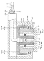
この雌コネクタ1を相手側ハウジング90に嵌合させる場合は、相手側ハウジング90をインナハウジング20の嵌合空間S1内において、端子収容部21とアウタハウジング30との間に挿入し、奥方へ進入させる。すると、相手側ハウジング90は、その外周面をアウタハウジング30(前方フード部31)の内周面31Aに対向または摺接させ、内周面をシールリング70の3条のリップ71A,71Bに摺接させつつ、その後端が後壁部23に所定の間隙を隔てて対向する位置まで進入する。これとともに、相手側端子91が雌端子11の角筒部の内部に挿入され、角筒部の天井内壁11Bとばね片11Aとの間に所定の接圧で挟持された状態で雌端子11に対して導電可能に接続される。
When fitting the
これにより、雌コネクタ1が相手側ハウジング90に嵌合した状態においては、インナハウジング20は、端子収容部21においてシールリング70を介して全周に亘って相手側ハウジング90の内周に密着するとともに、雌端子11と相手側端子91との接圧によって一体に保持されている。
As a result, when the
この状態において、第一ロック部50においてインナハウジング20の第一ロック片51R,51Lとアウタハウジング30の第一ロック突起55R,55Lとの間にはクリアランスCL2が設定されている。これにより、インナハウジング20はアウタハウジング30に対して相対移動が許容された状態となっている。
In this state, a clearance CL2 is set between the
一方、アウタハウジング30(前方フード部31)の内周面31A(相手側当接部の一例)は相手側ハウジング90の外周側に対して、寸法公差によるクリアランスCL1を隔てて対向し、相手側ハウジング90の外周側に当接可能となっている。
On the other hand, the inner
カバー部材40は、上述のようにアウタハウジング30に連結されるとともに、インナハウジング20から十分な間隙を隔ててこれを覆い、電線Wに固定されている。
The
この状態で電線Wが振動等により移動した場合、電線Wに固定されたカバー部材40は、電線Wに伴って移動してアウタハウジング30に当接し、アウタハウジング30はカバー部材40に押されて移動して相手側ハウジング90に当接し、それ以上の移動が規制された状態となる。この状態においても、インナハウジング20は上述のとおりアウタハウジング30に対して相対移動が可能な状態となっているから、電線Wからの振動はインナハウジング20に直接伝わることなくカバー部材40およびアウタハウジング30を介して相手側ハウジング90に逃がされる。すなわち、カバー部材40およびアウタハウジング30は、電線Wの振動を相手側ハウジング90に伝達するための振動伝達部材を構成している。
When the electric wire W moves due to vibration or the like in this state, the
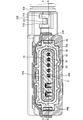
詳しくは、上述の通りアウタハウジング30と相手側ハウジング90とのクリアランスを第一クリアランスCL1、インナハウジング20とアウタハウジング30とのクリアランスを第二クリアランスCL2としたとき、本実施形態においては、第一クリアランスCL1と第二クリアランスCL2は、常にCL1<CL2(=式1)となるように寸法設定されている。
Specifically, when the clearance between the
より詳しくは、例えば図11に示すように、雌端子11および相手側端子91よりも左側におけるアウタハウジング30の内周面31Aと相手側ハウジング90とのクリアランスを左側第一クリアランスCL1_L、インナハウジング20とアウタハウジング30とのクリアランスを左側第二クリアランスCL2_Lとし、雌端子11および相手側端子91よりも右側におけるアウタハウジング30の内周面31Aと相手側ハウジング90とのクリアランスを右側第一クリアランスCL1_R、インナハウジング20とアウタハウジング30とのクリアランスを右側第二クリアランスCL2_Rとする。そして、アウタハウジング30が右方に移動し、相手側ハウジング90に接触した(つまり左側第一クリアランスCL1_Lの値がゼロとなった)とする。
More specifically, for example, as shown in FIG. 11, the clearance between the inner
このとき、インナハウジング20と相手側ハウジング90とは一体に固定されているため、右側第一クリアランスCL1_Rが最大となり、右側第二クリアランスCL2_Rは最小となる。しかし、上記の式よりCL1_RとCL2_Rとの間には常にCL1_R<CL2_R(=式1’)が成り立つようになっているから、右側第二クリアランスCL2_Rがゼロとなることはない。すなわち、アウタハウジング30が相手側ハウジング90にゼロ当たりした場合にも、雌端子11および相手側端子91を中心とした反対側において、インナハウジング20がアウタハウジング30に対して相対移動可能な状態が保たれる。
At this time, since the
これにより、カバー部材40が電線Wの振動を受けて雌端子11の軸方向に直交する方向に移動してアウタハウジング30に当接し衝撃を与えた場合にも、カバー部材40の内部空間においてインナハウジング20をアウタハウジング30に対して相対的にフロートさせつつ、アウタハウジング30を介して当接による衝撃を相手側ハウジング90に逃がすようになっている。
As a result, even when the
なお図示は省くが、これと同様に、雌端子11の軸方向においても、インナハウジング20およびアウタハウジング30は、各部位において第一クリアランスCL1<第二クリアランスCL2となるように寸法設定されている。
Although not shown, the
以上の構成により、本実施形態に係るコネクタ(雌コネクタ1)は、電線Wが外部に引き出されて相手側ハウジング90に嵌合するインナハウジング20と、前記相手側ハウジング90に当接可能とされた相手側当接部(内周面31A)を有する振動伝達部材30、40を備えるコネクタであって、前記振動伝達部材30、40は前記電線Wが固定される電線固定部43を有し、前記電線固定部43からの振動を前記相手側当接部31Aから前記相手側ハウジング90に伝達可能とされ、前記インナハウジング20は前記振動伝達部材30、40に対して相対移動が許容されている。
With the above configuration, the connector (female connector 1) according to the present embodiment is capable of contacting the
この構成によれば、電線Wが振動した場合、その振動は電線固定部43から振動伝達部材30、40を介して相手側ハウジング90に吸収されるから、電線Wからインナハウジング20に伝わる振動を減少させることができる。電線Wからインナハウジング20に振動が伝わったとしても、インナハウジング20は振動伝達部材30、40に対して相対移動が許容されているから、電線Wから伝わる振動を減衰させることができる。これにより、例えばインナハウジング20と相手側ハウジング90にそれぞれ端子11、91を収容し互いに接触させた場合、インナハウジング20の相対移動によって減衰させた振動を各端子11、91同士の接圧によって抑え込めるから、端子11,91同士の摺動による摩耗を抑制することができる。
According to this configuration, when the electric wire W vibrates, the vibration is absorbed from the electric
また、前記インナハウジング20は前記振動伝達部材30、40のロック突起55R,55Lが係止可能なロック片51R,51Lを備え、前記ロック突起55R,55Lと前記ロック片51R,51Lとの間には前記インナハウジング20の前記振動伝達部材30、40に対する相対移動を許容するクリアランスCL1が設けられている。
Further, the
この構成によれば、相手側ハウジング90に嵌合しない状態においてインナハウジング20のロック片51R,51Lを振動伝達部材30、40のロック突起55R,55Lに係止させておくことで、これらを一体的に取り扱うことが可能になる。また、ロック突起55R,55Lとロック片51R,51Lとの間にクリアランスCL1を設けているから、インナハウジング20の相対移動を確保しつつインナハウジング20と振動伝達部材30、40を一体的に取り扱うことができる。
According to this configuration, the
また、前記振動伝達部材30、40は、前記相手側当接部31Aを有し前記インナハウジング20を覆うアウタハウジング30と、前記電線固定部43を有し前記アウタハウジング30および前記電線Wを覆うカバー部材40と、を備える。
Further, the
この構成によれば、カバー部材40によってインナハウジング20、アウタハウジング30および電線Wを覆い、外部から保護することができる。
According to this configuration, the
また、前記アウタハウジング30は前記相手側ハウジング90に対して第一クリアランスCL1を隔てて対向するとともに、前記インナハウジング20に対して前記第一クリアランスCL1よりも大きい第二クリアランスCL2を隔てて対向する。
Further, the
この構成によれば、アウタハウジング30が相手側ハウジング90に当接しても(すなわち第一クリアランスCL1の寸法分だけ移動しても)、その移動距離は第二クリアランスCL2の寸法より小さいから、アウタハウジング30がインナハウジング20に当接することはなく、電線Wからの振動をインナハウジング20に直接伝えることがない。
According to this configuration, even if the
<他の実施形態>
本明細書に開示された技術は上記記述及び図面によって説明した実施形態に限定されるものではなく、例えば次のような形態で実施することが可能である。
<Other Embodiments>
The techniques disclosed herein are not limited to the embodiments described above and in the drawings, and can be implemented, for example, in the following embodiments.
(1)上記実施形態においては、振動伝達部材30、40をアウタハウジング30とカバー部材40とによって構成し、アウタハウジング30がカバー部材40に対して相対移動可能としているが、カバー部材がアウタハウジングに対して緊密に嵌合し、アウタハウジングがカバー部材に対してフロート動作しない構成としてもよい。これにより、電線からの振動をより確実に相手側ハウジングに逃がすことができる。または、カバー部材とアウタハウジングとを一体化させた振動伝達部材としてもよい。これにより、部品数を減らすことができる。
(2)上記実施形態においては、電線固定部43を電線管43Aと後側開口部43Bとによって構成するものとしたが、電線固定部43の構成はこれに限らない。例えば、後側開口部43Bを電線Wに対応した内径および形状とし、後側開口部43Bに直接電線Wを緊密に挿通させる形状としてもよい。
(1) In the above embodiment, the
(2) In the above embodiment, the electric
(3)上記実施形態においてはカバー部材40が振動伝達部材を構成する構成としたが、振動伝達部材はカバー部材40とは別途に設けられてもよく、この場合カバー部材40はなくてもよい。
(3) In the above embodiment, the
(4)上記実施形態においてはインナハウジング20およびアウタハウジング30を第一ロック部50によって一体的に取り扱う構成としたが、第一ロック部を設けず、インナハウジングとアウタハウジングを別部材として扱ってもよい。これにより、雌ハウジングに相手側ハウジングが嵌合した状態においてインナハウジングをアウタハウジングに対して非接触の状態とすることができるから、インナハウジングに電線からの振動が伝わることをより効果的に防ぐことができる。
(4) In the above embodiment, the
(5)上記実施形態においては、アウタハウジング30は相手側ハウジング90に対して第一クリアランスCL1を隔てて対向するとともに、前記インナハウジング20に対して前記第一クリアランスCL1よりも大きい第二クリアランスCL2を隔てて対向するものとしたが、アウタハウジングが相手側ハウジングに対して密着する構成(すなわち第一クリアランスがゼロ)であってもよい。これにより、電線からの振動をより確実に相手側ハウジングに逃がすことができる。
(5) In the above embodiment, the
1:雌コネクタ(コネクタ)
20:インナハウジング
30:アウタハウジング(振動伝達部材)
31A:内周面(相手側当接部)
40:カバー部材(振動伝達部材)
43:電線固定部
90:相手側ハウジング
CL1:第一クリアランス
CL2:第二クリアランス
1: Female connector (connector)
20: Inner housing 30: Outer housing (vibration transmission member)
31A: Inner peripheral surface (contact part on the other side)
40: Cover member (vibration transmission member)
43: Wire fixing part 90: Mating side housing CL1: First clearance CL2: Second clearance
Claims (3)
前記相手側ハウジングに当接可能とされた相手側当接部を有する振動伝達部材と、を備えるコネクタであって、
前記振動伝達部材は、前記相手側当接部を有し前記インナハウジングを覆うアウタハウジングと、電線固定部を有し前記アウタハウジングおよび前記電線を覆うカバー部材と、を備え、
前記アウタハウジングの前端部に連結受け部が設けられ、前記カバー部材の前端部に連結部が設けられ、前記連結部が前記連結受け部に嵌められることで前記カバー部材が前記アウタハウジングに連結されており、
前記振動伝達部材は、前記電線固定部からの振動を前記連結部から前記連結受け部に伝達可能とされ、前記相手側当接部から前記相手側ハウジングに伝達可能とされ、
前記インナハウジングは前記アウタハウジングに対して相対移動が許容されているコネクタ。 The inner housing where the electric wire is pulled out and fits into the mating housing,
A connector comprising a vibration transmitting member having a mating side contact portion that can be brought into contact with the mating side housing.
The vibration transmission member includes an outer housing having a mating portion and covering the inner housing, and a cover member having an electric wire fixing portion and covering the outer housing and the electric wire.
A connecting receiving portion is provided at the front end portion of the outer housing, a connecting portion is provided at the front end portion of the cover member, and the cover member is connected to the outer housing by fitting the connecting portion into the connecting receiving portion. And
The vibration transmitting member is capable of transmitting vibration from the electric wire fixing portion from the connecting portion to the connecting receiving portion, and is capable of transmitting the vibration from the mating end contact portion to the mating housing.
The inner housing is a connector that allows relative movement with respect to the outer housing.
前記ロック突起と前記ロック片との間には前記インナハウジングの前記振動伝達部材に対する相対移動を許容するクリアランスが設けられている請求項1に記載のコネクタ。 The inner housing includes a lock piece to which the lock protrusion of the vibration transmission member can be locked.
The connector according to claim 1, wherein a clearance is provided between the lock protrusion and the lock piece to allow relative movement of the inner housing with respect to the vibration transmitting member.
Priority Applications (4)
| Application Number | Priority Date | Filing Date | Title |
|---|---|---|---|
| JP2017215640A JP6889840B2 (en) | 2017-11-08 | 2017-11-08 | connector |
| US16/762,910 US11189963B2 (en) | 2017-11-08 | 2018-11-06 | Connector |
| PCT/JP2018/041105 WO2019093298A1 (en) | 2017-11-08 | 2018-11-06 | Connector |
| CN201880068595.0A CN111316507B (en) | 2017-11-08 | 2018-11-06 | Connector with a locking member |
Applications Claiming Priority (1)
| Application Number | Priority Date | Filing Date | Title |
|---|---|---|---|
| JP2017215640A JP6889840B2 (en) | 2017-11-08 | 2017-11-08 | connector |
Publications (2)
| Publication Number | Publication Date |
|---|---|
| JP2019087450A JP2019087450A (en) | 2019-06-06 |
| JP6889840B2 true JP6889840B2 (en) | 2021-06-18 |
Family
ID=66438446
Family Applications (1)
| Application Number | Title | Priority Date | Filing Date |
|---|---|---|---|
| JP2017215640A Active JP6889840B2 (en) | 2017-11-08 | 2017-11-08 | connector |
Country Status (4)
| Country | Link |
|---|---|
| US (1) | US11189963B2 (en) |
| JP (1) | JP6889840B2 (en) |
| CN (1) | CN111316507B (en) |
| WO (1) | WO2019093298A1 (en) |
Families Citing this family (5)
| Publication number | Priority date | Publication date | Assignee | Title |
|---|---|---|---|---|
| JP7521488B2 (en) * | 2021-05-28 | 2024-07-24 | 住友電装株式会社 | connector |
| EP4106114A1 (en) * | 2021-06-14 | 2022-12-21 | Vitesco Technologies GmbH | High temperature sensor housing with thermocouple connectors, and method for manufacturing the same |
| US12100911B2 (en) | 2021-11-03 | 2024-09-24 | Deere & Company | Vibration resistant connector cap |
| US12003058B2 (en) * | 2021-11-03 | 2024-06-04 | Deere & Company | Vibration resistant connector cap |
| JP7630772B2 (en) * | 2021-11-24 | 2025-02-18 | 株式会社オートネットワーク技術研究所 | connector |
Family Cites Families (20)
| Publication number | Priority date | Publication date | Assignee | Title |
|---|---|---|---|---|
| JPH04233176A (en) * | 1990-12-28 | 1992-08-21 | Amp Japan Ltd | Plug connector |
| JP2002008769A (en) | 2000-06-27 | 2002-01-11 | Yazaki Corp | connector |
| EP1170828B1 (en) | 2000-07-06 | 2012-01-11 | Yazaki Corporation | Protective cover |
| JP2002025684A (en) * | 2000-07-06 | 2002-01-25 | Yazaki Corp | Protective cover |
| DE20013282U1 (en) * | 2000-08-02 | 2001-12-13 | Robert Bosch Gmbh, 70469 Stuttgart | Wiring harness connector with a fixing device for the wiring harness |
| JP3883436B2 (en) | 2002-01-17 | 2007-02-21 | 利彦 深澤 | earrings |
| JP2006086091A (en) * | 2004-09-17 | 2006-03-30 | Sumitomo Wiring Syst Ltd | Connector |
| JP4554376B2 (en) * | 2005-01-14 | 2010-09-29 | 矢崎総業株式会社 | connector |
| JP4525397B2 (en) * | 2005-03-15 | 2010-08-18 | トヨタ自動車株式会社 | connector |
| JP4558619B2 (en) * | 2005-09-30 | 2010-10-06 | 矢崎総業株式会社 | connector |
| JP4973430B2 (en) | 2007-10-05 | 2012-07-11 | 住友電装株式会社 | connector |
| JP5353676B2 (en) * | 2009-12-16 | 2013-11-27 | 住友電装株式会社 | connector |
| US8926363B2 (en) * | 2012-03-02 | 2015-01-06 | Tyco Electronics Corporation | Electrical connector assembly |
| JP5946377B2 (en) * | 2012-09-07 | 2016-07-06 | 矢崎総業株式会社 | connector |
| JP2014086350A (en) * | 2012-10-25 | 2014-05-12 | Sumitomo Wiring Syst Ltd | Shield connector |
| JP5741560B2 (en) * | 2012-11-28 | 2015-07-01 | 住友電装株式会社 | Connector for equipment |
| DE102014015715A1 (en) * | 2014-04-02 | 2015-10-08 | Kostal Kontakt Systeme Gmbh | Multipole electrical connector part |
| JP2017073301A (en) * | 2015-10-08 | 2017-04-13 | 住友電装株式会社 | connector |
| JP6548035B2 (en) * | 2016-01-29 | 2019-07-24 | 住友電装株式会社 | connector |
| KR102405699B1 (en) * | 2017-03-02 | 2022-06-07 | 현대자동차주식회사 | Connector device |
-
2017
- 2017-11-08 JP JP2017215640A patent/JP6889840B2/en active Active
-
2018
- 2018-11-06 CN CN201880068595.0A patent/CN111316507B/en active Active
- 2018-11-06 US US16/762,910 patent/US11189963B2/en active Active
- 2018-11-06 WO PCT/JP2018/041105 patent/WO2019093298A1/en not_active Ceased
Also Published As
| Publication number | Publication date |
|---|---|
| JP2019087450A (en) | 2019-06-06 |
| CN111316507B (en) | 2021-07-30 |
| WO2019093298A1 (en) | 2019-05-16 |
| US20210175661A1 (en) | 2021-06-10 |
| CN111316507A (en) | 2020-06-19 |
| US11189963B2 (en) | 2021-11-30 |
Similar Documents
| Publication | Publication Date | Title |
|---|---|---|
| JP6889840B2 (en) | connector | |
| JP6548036B2 (en) | connector | |
| CN108258535B (en) | Connector with a locking member | |
| CN107658617A (en) | Connector | |
| JP6580548B2 (en) | connector | |
| CN105308801A (en) | Connector | |
| CN107710519A (en) | Connector and connector joint structure | |
| CN107026353A (en) | Connector | |
| JP2017010754A (en) | Connector cover | |
| JP2020113478A (en) | connector | |
| CN108352644B (en) | Connector | |
| CN115700947A (en) | Connector | |
| US20180226745A1 (en) | Wire cover member | |
| JP2018018584A (en) | connector | |
| CN103682790B (en) | Connector | |
| JP2012119075A (en) | connector | |
| US20170264047A1 (en) | Connector for camera | |
| JP6955677B2 (en) | connector | |
| CN109792123B (en) | Connector | |
| JP2012169056A (en) | Filter member for connector, connector assembly, assembling method of connector assembly | |
| JP6846188B2 (en) | connector | |
| JP7182092B2 (en) | connector structure | |
| JP5189425B2 (en) | Connector seal structure and packing | |
| CN108321596B (en) | Connector | |
| JP6611307B2 (en) | connector |
Legal Events
| Date | Code | Title | Description |
|---|---|---|---|
| A621 | Written request for application examination |
Free format text: JAPANESE INTERMEDIATE CODE: A621 Effective date: 20200228 |
|
| A131 | Notification of reasons for refusal |
Free format text: JAPANESE INTERMEDIATE CODE: A131 Effective date: 20210126 |
|
| A521 | Request for written amendment filed |
Free format text: JAPANESE INTERMEDIATE CODE: A523 Effective date: 20210317 |
|
| TRDD | Decision of grant or rejection written | ||
| A01 | Written decision to grant a patent or to grant a registration (utility model) |
Free format text: JAPANESE INTERMEDIATE CODE: A01 Effective date: 20210422 |
|
| A61 | First payment of annual fees (during grant procedure) |
Free format text: JAPANESE INTERMEDIATE CODE: A61 Effective date: 20210505 |
|
| R150 | Certificate of patent or registration of utility model |
Ref document number: 6889840 Country of ref document: JP Free format text: JAPANESE INTERMEDIATE CODE: R150 |
|
| R250 | Receipt of annual fees |
Free format text: JAPANESE INTERMEDIATE CODE: R250 |
|
| R250 | Receipt of annual fees |
Free format text: JAPANESE INTERMEDIATE CODE: R250 |
|
| R250 | Receipt of annual fees |
Free format text: JAPANESE INTERMEDIATE CODE: R250 |