JP6889772B2 - Spray chambers and how to use them - Google Patents
Spray chambers and how to use them Download PDFInfo
- Publication number
- JP6889772B2 JP6889772B2 JP2019512942A JP2019512942A JP6889772B2 JP 6889772 B2 JP6889772 B2 JP 6889772B2 JP 2019512942 A JP2019512942 A JP 2019512942A JP 2019512942 A JP2019512942 A JP 2019512942A JP 6889772 B2 JP6889772 B2 JP 6889772B2
- Authority
- JP
- Japan
- Prior art keywords
- cells
- outer chamber
- chamber
- spray chamber
- spray
- Prior art date
- Legal status (The legal status is an assumption and is not a legal conclusion. Google has not performed a legal analysis and makes no representation as to the accuracy of the status listed.)
- Active
Links
Images


Classifications
-
- H—ELECTRICITY
- H01—ELECTRIC ELEMENTS
- H01J—ELECTRIC DISCHARGE TUBES OR DISCHARGE LAMPS
- H01J49/00—Particle spectrometers or separator tubes
- H01J49/02—Details
- H01J49/10—Ion sources; Ion guns
- H01J49/107—Arrangements for using several ion sources
-
- H—ELECTRICITY
- H01—ELECTRIC ELEMENTS
- H01J—ELECTRIC DISCHARGE TUBES OR DISCHARGE LAMPS
- H01J49/00—Particle spectrometers or separator tubes
- H01J49/02—Details
- H01J49/04—Arrangements for introducing or extracting samples to be analysed, e.g. vacuum locks; Arrangements for external adjustment of electron- or ion-optical components
- H01J49/0431—Arrangements for introducing or extracting samples to be analysed, e.g. vacuum locks; Arrangements for external adjustment of electron- or ion-optical components for liquid samples
- H01J49/0445—Arrangements for introducing or extracting samples to be analysed, e.g. vacuum locks; Arrangements for external adjustment of electron- or ion-optical components for liquid samples with means for introducing as a spray, a jet or an aerosol
- H01J49/045—Arrangements for introducing or extracting samples to be analysed, e.g. vacuum locks; Arrangements for external adjustment of electron- or ion-optical components for liquid samples with means for introducing as a spray, a jet or an aerosol with means for using a nebulising gas, i.e. pneumatically assisted
-
- G—PHYSICS
- G01—MEASURING; TESTING
- G01N—INVESTIGATING OR ANALYSING MATERIALS BY DETERMINING THEIR CHEMICAL OR PHYSICAL PROPERTIES
- G01N30/00—Investigating or analysing materials by separation into components using adsorption, absorption or similar phenomena or using ion-exchange, e.g. chromatography or field flow fractionation
- G01N30/02—Column chromatography
- G01N30/62—Detectors specially adapted therefor
- G01N30/72—Mass spectrometers
- G01N30/7233—Mass spectrometers interfaced to liquid or supercritical fluid chromatograph
- G01N30/7273—Desolvation chambers
-
- H—ELECTRICITY
- H01—ELECTRIC ELEMENTS
- H01J—ELECTRIC DISCHARGE TUBES OR DISCHARGE LAMPS
- H01J49/00—Particle spectrometers or separator tubes
- H01J49/02—Details
- H01J49/04—Arrangements for introducing or extracting samples to be analysed, e.g. vacuum locks; Arrangements for external adjustment of electron- or ion-optical components
- H01J49/0468—Arrangements for introducing or extracting samples to be analysed, e.g. vacuum locks; Arrangements for external adjustment of electron- or ion-optical components with means for heating or cooling the sample
- H01J49/049—Arrangements for introducing or extracting samples to be analysed, e.g. vacuum locks; Arrangements for external adjustment of electron- or ion-optical components with means for heating or cooling the sample with means for applying heat to desorb the sample; Evaporation
-
- H—ELECTRICITY
- H01—ELECTRIC ELEMENTS
- H01J—ELECTRIC DISCHARGE TUBES OR DISCHARGE LAMPS
- H01J49/00—Particle spectrometers or separator tubes
- H01J49/02—Details
- H01J49/10—Ion sources; Ion guns
- H01J49/16—Ion sources; Ion guns using surface ionisation, e.g. field-, thermionic- or photo-emission
- H01J49/165—Electrospray ionisation
- H01J49/167—Capillaries and nozzles specially adapted therefor
-
- H—ELECTRICITY
- H01—ELECTRIC ELEMENTS
- H01J—ELECTRIC DISCHARGE TUBES OR DISCHARGE LAMPS
- H01J49/00—Particle spectrometers or separator tubes
- H01J49/02—Details
- H01J49/10—Ion sources; Ion guns
- H01J49/105—Ion sources; Ion guns using high-frequency excitation, e.g. microwave excitation, Inductively Coupled Plasma [ICP]
Description
優先出願
本出願は、2016年5月18日に提出された米国仮出願第62/337,997号に関し、それに対する優先権及びその利益を主張しており、その開示全体は、全ての目的のために参照により本明細書にこれにより組み込まれている。
Priority Application This application claims priority and interests in US Provisional Application No. 62 / 337,997 filed May 18, 2016, the entire disclosure of which is for all purposes. For reference herein incorporated herein by reference.
本明細書に開示される特定の例は、噴霧チャンバ、及び単一分子または単一細胞の分析におけるその利用に関する。より詳細には、本明細書に記載される特定の例は、噴霧チャンバ、及びプラズマまたは他のイオン化源もしくはイオン化装置の中に試料を投入するためのその利用を対象としている。 Specific examples disclosed herein relate to spray chambers and their use in single molecule or single cell analysis. More specifically, the particular examples described herein are intended for spray chambers and their use for placing samples into plasma or other ionization sources or devices.
試料をイオン化する及び/または霧化するのにプラズマが使用されてよい。液体試料は典型的には、1つまたは複数の試料投入装置を介してエアロゾルの形態でプラズマに提供される。 Plasma may be used to ionize and / or atomize the sample. The liquid sample is typically provided to the plasma in the form of an aerosol via one or more sample loading devices.
イオン化装置またはイオン化源と共に利用するのに適した多くの異なる形態の噴霧チャンバの一部を例示するために、噴霧チャンバの特定の態様、例、実施形態及び構成が、より詳細に以下に記載される。 Specific embodiments, examples, embodiments and configurations of the spray chamber are described in more detail below to illustrate some of the many different forms of spray chamber suitable for use with an ionizer or ion source. To.
第1の態様において、液体試料をネブライザーから受け取るために入口端部においてネブライザーに結合し、エアロゾル化された試料の噴霧を出口端部においてイオン化装置に提供するように構成された噴霧チャンバが提供される。一部の構成では、噴霧チャンバは、入口端部、出口端部及び外側チャンバ内に接線方向のガス流を提供するために気体を受け取るように各々構成された二重のメイクアップガス入口ポートを備える外側チャンバと、外側チャンバ内にあり、二重のメイクアップガス入口から外側チャンバ内に投入されるメイクアップガスを受容するように構成された複数の内部のマイクロチャネルを備える内側の管とを備え、内側の管は、内側の管上での液滴の沈着を抑えるために、内側の管の外側面と、外側チャンバの内側面との間に層流を提供するようにサイズが決められ、そのように配置されている。 In a first aspect, a nebulizer is provided that is configured to couple to the nebulizer at the inlet end to receive the liquid sample from the nebulizer and to provide a spray of the aerosolized sample to the ionizer at the outlet end. To. In some configurations, the spray chamber has double make-up gas inlet ports, each configured to receive gas to provide tangential gas flow into the inlet, outlet and outer chambers. An outer chamber with an inner tube that is inside the outer chamber and has multiple internal microchannels that are configured to receive make-up gas that is injected into the outer chamber through a double make-up gas inlet. The inner tube is sized to provide laminar flow between the outer surface of the inner tube and the inner surface of the outer chamber to reduce the deposition of droplets on the inner tube. , Is arranged that way.
特定の例では、複数のマイクロチャネルの少なくとも1つのマイクロチャネルは、受け取った液体試料の逆流を阻止するように位置決めされる。一部の実施形態では、外側チャンバは、層流を促進するために入口端部に丸められた縁部を備える。他の例では、二重のメイクアップガス入口は、同一の半径方向の面内に位置決めされる。一部の例では、外側チャンバは、排水ポートをさらに備える。他の例では、内側の管は、円錐形状を有する。一部の例では、外側チャンバの内径は、入口端部においてよりも出口端部においてより小さい。追加の例では、二重のメイクアップガス入口は、外側チャンバの入口端部に隣接して位置決めされる。他の例では、二重のメイクアップガス入口は、外側チャンバの出口端部に隣接して位置決めされる。一部の例では、内側の管の内径は、外側チャンバの入口端部から、外側チャンバの出口端部に向かって長手方向に大きくなる。一部の実施形態では、内側の管の内径は、外側チャンバの入口端部から、外側チャンバの出口端部に向かって長手方向に小さくなる。 In a particular example, at least one of the plurality of microchannels is positioned to prevent backflow of the received liquid sample. In some embodiments, the outer chamber comprises a rounded edge at the inlet end to facilitate laminar flow. In another example, the double make-up gas inlets are positioned in the same radial plane. In some examples, the outer chamber further comprises a drain port. In another example, the inner tube has a conical shape. In some examples, the inner diameter of the outer chamber is smaller at the outlet end than at the inlet end. In an additional example, the double make-up gas inlet is positioned adjacent to the inlet end of the outer chamber. In another example, the double make-up gas inlet is positioned adjacent to the outlet end of the outer chamber. In some examples, the inner diameter of the inner tube increases longitudinally from the inlet end of the outer chamber towards the outlet end of the outer chamber. In some embodiments, the inner diameter of the inner tube decreases longitudinally from the inlet end of the outer chamber towards the outlet end of the outer chamber.
特定の構成において、外側チャンバは、入口端部に隣接して二重のメイクアップガス入口を備え、内側の管の内径は、外側チャンバの入口端部から、外側チャンバの出口端部に向かって長手方向に大きくなり、外側チャンバの内径は、入口端部においてよりも出口端部において小さくなる。 In certain configurations, the outer chamber has a double make-up gas inlet adjacent to the inlet end, and the inner diameter of the inner tube is from the inlet end of the outer chamber towards the outlet end of the outer chamber. It increases in the longitudinal direction and the inner diameter of the outer chamber is smaller at the outlet end than at the inlet end.
他の構成では、外側チャンバは、入口端部に隣接して二重のメイクアップガス入口を備え、内側の管の内径は長手方向においてほぼ一定であり、外側チャンバの内径は、入口端部においてよりも出口端部において小さくなる。 In other configurations, the outer chamber has a double make-up gas inlet adjacent to the inlet end, the inner diameter of the inner tube is approximately constant in the longitudinal direction, and the inner diameter of the outer chamber is at the inlet end. It becomes smaller at the exit end than.
一部の構成では、外側チャンバは、出口端部に隣接して二重のメイクアップガス入口を備え、内側の管の内径は、外側チャンバの入口端部においてよりも外側チャンバの出口端部においてより小さくなり、外側チャンバの内径は、入口端部から出口端部までほぼ一定である。 In some configurations, the outer chamber has a double make-up gas inlet adjacent to the outlet end, and the inner diameter of the inner tube is at the outlet end of the outer chamber rather than at the inlet end of the outer chamber. It becomes smaller and the inner diameter of the outer chamber is almost constant from the inlet end to the outlet end.
一部の例では、外側チャンバは、入口端部において内部の丸められた縁部を備える。
別の態様において、噴霧チャンバは、入口端部において液体試料送達装置に流体結合し、出口端部において単一の粒子または単一の細胞を選択し、噴霧チャンバに流体結合されたイオン化装置に噴霧するように構成される場合がある。一部の実施形態では、噴霧チャンバは、外側チャンバ内に接線方向のガス流を提供するために、メイクアップガスを提供するように構成されたメイクアップガス源に流体結合するように各々構成された二重のガス入口ポートを備える外側チャンバを備える。一部の例では、噴霧チャンバは、外側チャンバ内にあり、そこに結合された内側の管をさらに備える。一部の例では、内側の管は、液体試料の液滴が内側の管の表面に沈着するのを阻止するためにメイクアップガスを受容するように各々構成された複数のマイクロチャネルを備える。一部の構成では、内側の管は、外側チャンバの内側面上での液滴の形成を阻止するために、外側チャンバ内に層流を提供するように位置決めされる。
In some examples, the outer chamber comprises an inner rounded edge at the inlet end.
In another embodiment, the spray chamber fluidly binds to the liquid sample delivery device at the inlet end, selects a single particle or single cell at the outlet end and sprays onto the ionizer fluidized to the spray chamber. May be configured to. In some embodiments, the spray chambers are each configured to fluidly bond to a make-up gas source configured to provide make-up gas in order to provide a tangential gas flow within the outer chamber. It has an outer chamber with a double gas inlet port. In some examples, the spray chamber is inside the outer chamber and further comprises an inner tube coupled therein. In some examples, the inner tube comprises multiple microchannels, each configured to receive make-up gas to prevent droplets of liquid sample from depositing on the surface of the inner tube. In some configurations, the inner tube is positioned to provide laminar flow within the outer chamber to prevent the formation of droplets on the inner surface of the outer chamber.
特定の例では、複数のマイクロチャネルの少なくとも1つのマイクロチャネルは、外側チャンバ内での液体試料の逆流を阻止するように位置決めされる。他の例では、外側チャンバは、層流を促進するために入口端部に丸められた縁部を備える。一部の例では、二重のガス入口は、同一の半径方向の面内に位置決めされる。一部の実施形態では、外側チャンバは、排水ポートをさらに備える。特定の例では、内側の管は円錐形状を有する。一部の構成では、外側チャンバの内径は、入口端部においてよりも出口端部においてより小さい。他の構成では、二重のガス入口は、外側チャンバの入口端部に隣接して位置決めされる。特定の例では、二重のガス入口は、外側チャンバの出口端部に隣接して位置決めされる。一部の実施形態において、内側の管の内径は、外側チャンバの入口端部から、外側チャンバの出口端部に向かって長手方向に大きくなる。他の実施形態において、内側の管の内径は、外側チャンバの入口端部から、外側チャンバの出口端部に向かって長手方向に小さくなる。 In a particular example, at least one of the plurality of microchannels is positioned to prevent backflow of the liquid sample in the outer chamber. In another example, the outer chamber comprises a rounded edge at the inlet end to facilitate laminar flow. In some examples, the double gas inlets are positioned in the same radial plane. In some embodiments, the outer chamber further comprises a drain port. In certain examples, the inner tube has a conical shape. In some configurations, the inner diameter of the outer chamber is smaller at the outlet end than at the inlet end. In other configurations, the double gas inlet is positioned adjacent to the inlet end of the outer chamber. In a particular example, the double gas inlet is positioned adjacent to the outlet end of the outer chamber. In some embodiments, the inner diameter of the inner tube increases longitudinally from the inlet end of the outer chamber towards the outlet end of the outer chamber. In another embodiment, the inner diameter of the inner tube decreases longitudinally from the inlet end of the outer chamber towards the outlet end of the outer chamber.
特定の例では、外側チャンバは、入口端部に隣接して二重のガス入口を備え、内側の管の内径は、外側チャンバの入口端部から外側チャンバの出口端部に向かって長手方向に大きくなり、外側チャンバの内径は、入口端部においてより出口端部においてより小さい。 In a particular example, the outer chamber has a double gas inlet adjacent to the inlet end, and the inner diameter of the inner tube is longitudinal from the inlet end of the outer chamber to the outlet end of the outer chamber. It becomes larger and the inner diameter of the outer chamber is smaller at the outlet end than at the inlet end.
他の構成では、外側チャンバは、入口端部に隣接して二重のガス入口を備え、内側の管の内径は長手方向においてほぼ一定であり、外側チャンバの内径は、入口端部においてよりも出口端部においてより小さい。 In other configurations, the outer chamber has a double gas inlet adjacent to the inlet end, the inner diameter of the inner tube is approximately constant in the longitudinal direction, and the inner diameter of the outer chamber is greater than at the inlet end. Smaller at the exit end.
一部の構成では、外側チャンバは、出口端部に隣接して二重のガス入口を備え、内側の管の内径は、外側チャンバの入口端部においてよりも外側チャンバの出口端部においてより小さくなり、外側チャンバの内径は、入口端部から出口端部までほぼ一定である。 In some configurations, the outer chamber has a double gas inlet adjacent to the outlet end, and the inner diameter of the inner tube is smaller at the outlet end of the outer chamber than at the inlet end of the outer chamber. Therefore, the inner diameter of the outer chamber is almost constant from the inlet end to the outlet end.
特定の例では、外側チャンバは、入口端部において内部の丸められた縁部を備える。
追加の態様において、噴霧チャンバは、外側チャンバ内に接線方向のガス流を提供するために、メイクアップガスを提供するように構成されたメイクアップガス源に流体結合するように各々構成された二重のガス入口ポートを備える外側チャンバを備える。例えば、噴霧チャンバは、入口端部において液体試料送達装置に流体結合し、出口端部において、エアロゾル化した検体を噴霧チャンバに流体結合されたイオン化装置に噴霧するように構成することができる。一部の例では、二重のガス入口ポートは、外側チャンバ内に接線方向のガス流を提供するのを助けるために異なる長手方向の面内に位置決めされる。
In certain examples, the outer chamber comprises an inner rounded edge at the inlet end.
In an additional aspect, the spray chambers are each configured to fluidly bond to a make-up gas source configured to provide make-up gas in order to provide a tangential gas flow within the outer chamber. It has an outer chamber with a heavy gas inlet port. For example, the spray chamber can be configured to fluidly bond to a liquid sample delivery device at the inlet end and spray the aerosolized sample to an ionizer fluidly coupled to the spray chamber at the outlet end. In some examples, the dual gas inlet ports are positioned in different longitudinal planes to help provide tangential gas flow into the outer chamber.
特定の構成では、外側チャンバは、層流を促進するために、入口端部において丸められた縁部を備える。他の構成では、外側チャンバは、排水ポートをさらに備える。一部の例では、二重のガス入口は、外側チャンバの入口端部に隣接して位置決めされる、または二重のガス入口は、外側チャンバの出口端部に隣接して位置決めされる。一部の実施形態において、外側チャンバの外径は、長手方向にほぼ一定である。他の例では、噴霧チャンバは、外側チャンバ内に位置決めされた内側の管を備え、内側の管は、液体試料の液滴が内側の管の表面に沈着するのを阻止するためにメイクアップガスを受容するように各々構成された複数のマイクロチャネルを備え、内側の管は、外側チャンバの内側面上での液滴の形成を阻止するために外側チャンバ内の層流を提供するように位置決めされる。 In certain configurations, the outer chamber comprises a rounded edge at the inlet end to facilitate laminar flow. In other configurations, the outer chamber further comprises a drain port. In some examples, the double gas inlet is positioned adjacent to the inlet end of the outer chamber, or the double gas inlet is positioned adjacent to the outlet end of the outer chamber. In some embodiments, the outer diameter of the outer chamber is substantially constant in the longitudinal direction. In another example, the spray chamber comprises an inner tube positioned within the outer chamber, which is a make-up gas to prevent droplets of liquid sample from depositing on the surface of the inner tube. With multiple microchannels, each configured to receive, the inner tube is positioned to provide laminar flow within the outer chamber to prevent the formation of droplets on the inner surface of the outer chamber. Will be done.
別の態様において、細胞集団における単一の細胞内で無機種または有機種を分析する方法は、本明細書に記載されるような噴霧チャンバ内に細胞集団を投入することと、投入された細胞集団から単一の細胞を選択することと、選択された単一の細胞をイオン化装置内に噴霧して、選択された単一の細胞内の無機種または有機種を分析することと、噴霧され、選択された単一細胞内の少なくとも1つの無機種または有機種を検出することとを含む。 In another embodiment, methods of analyzing an inorganic or organic species within a single cell in a cell population include placing the cell population into a spray chamber as described herein and the charged cells. Selecting a single cell from the population and spraying the selected single cell into an ionizer to analyze the inorganic or organic species within the selected single cell and spraying Includes detecting at least one inorganic or organic species within a selected single cell.
特定の例において、方法は、内胚葉、外胚葉または中胚葉由来の哺乳類細胞であるように細胞集団を選択することを含む。いくつかの実施形態において、方法は、選択された単一細胞内の少なくとも1つの金属種を検出することを含む。特定の例において、方法は、選択された細胞内の少なくとも1つのタンパク質を検出することを含む。他の例では、方法は、選択された単一細胞内の少なくとも1つの脂質を検出することを含む。特定の実施形態において、方法は、選択された単一細胞内の少なくとも1つの炭水化物を検出することを含む。他の実施形態において、方法は、選択された単一細胞内の少なくとも1つの核酸を検出することを含む。一部の例では、方法は、選択された単一細胞によって取り込まれた外部物質のレベルを検出することを含む。特定の例では、方法は、イオン化装置を誘導結合プラズマであるように構成することを含む。他の例では、方法は、質量分析計を利用して、イオン化装置内に噴霧される選択された単一細胞から無機種または有機種を検出することを含む。一部の例では、方法は、発光分光分析計を利用して、イオン化装置内に噴霧される選択された単一細胞から無機種または有機種を検出することを含む。他の例では、方法は、原子吸光分析計を利用して、イオン化装置に噴霧される選択された単一細胞から無機種または有機種を検出することを含む。特定の実施形態では、方法は、イオン化装置を、トーチと、誘導コイル、トーチと、放射状のフィンを備える誘導コイル、またはトーチと、少なくとも1つの平板電極として構成することを含む。 In certain examples, the method comprises selecting a cell population to be mammalian cells from endoderm, ectoderm or mesoderm. In some embodiments, the method comprises detecting at least one metal species within a selected single cell. In certain examples, the method comprises detecting at least one protein in selected cells. In another example, the method comprises detecting at least one lipid within a selected single cell. In certain embodiments, the method comprises detecting at least one carbohydrate within a selected single cell. In other embodiments, the method comprises detecting at least one nucleic acid within a selected single cell. In some examples, the method involves detecting the level of external material taken up by a single cell of choice. In certain examples, the method comprises configuring the ionizer to be an inductively coupled plasma. In another example, the method comprises utilizing a mass spectrometer to detect inorganic or organic species from selected single cells sprayed into an ionizer. In some examples, the method comprises utilizing an emission spectrometer to detect inorganic or organic species from selected single cells sprayed into an ionizer. In another example, the method comprises utilizing an atomic absorption spectrometer to detect inorganic or organic species from selected single cells that are sprayed onto an ionizer. In certain embodiments, the method comprises configuring the ionizer as a torch and an induction coil, a torch, an induction coil with radial fins, or a torch and at least one plate electrode.
追加の態様において、細胞集団における単一細胞内の無機種または有機種を検出する方法は、本明細書に記載されるような噴霧チャンバを提供することと、細胞集団から単一細胞を選択するため、及びイオン化装置を利用して、選択された単一細胞内の少なくとも1つの無機種または有機種を検出するために、提供された噴霧チャンバを利用するための説明を提供することとを含む。 In an additional embodiment, the method of detecting an inorganic or organic species within a single cell in a cell population provides a spray chamber as described herein and selects a single cell from the cell population. And to provide an explanation for utilizing the provided spray chamber to detect at least one inorganic or organic species within a selected single cell using an ionizer. ..
特定の例では、方法は、選択された単一細胞内の少なくとも1つの無機種または有機種を検出するために、誘導結合質量分析計と共に噴霧チャンバを利用するための説明を提供することを含む。一部の例では、方法は、選択された単一細胞内の少なくとも1つの無機種または有機種を検出するために、誘導結合発光分光分析計と共に噴霧チャンバを利用するための説明を提供することを含む。他の例では、方法は、選択された単一細胞内の少なくとも1つの無機種または有機種を検出するために、誘導結合原子吸光分析計と共に噴霧チャンバを利用するための説明を提供することを含む。追加の例では、方法は、単一の哺乳類の細胞を選択するために哺乳類の細胞集団を利用するための説明を提供することを含む。 In certain examples, the method comprises providing an explanation for utilizing a spray chamber with an inductively coupled mass spectrometer to detect at least one inorganic or organic species within a selected single cell. .. In some examples, the method provides an explanation for utilizing a spray chamber with an inductively coupled luminescence spectrometer to detect at least one inorganic or organic species within a selected single cell. including. In another example, the method provides an explanation for utilizing a spray chamber with an inductively coupled atomic absorption spectrometer to detect at least one inorganic or organic species within a selected single cell. Including. In an additional example, the method comprises providing an explanation for utilizing a mammalian cell population to select a single mammalian cell.
別の態様では、本明細書に記載されるような噴霧チャンバと、噴霧チャンバに流体結合された誘導装置と、誘導装置に流体結合された質量分析器とを備える質量分析計が開示されている。 In another aspect, a mass spectrometer is disclosed that includes a spray chamber as described herein, a guide that is fluid-coupled to the spray chamber, and a mass spectrometer that is fluid-coupled to the guide. ..
特定の例では、質量分析計は、噴霧チャンバに流体結合されたネブライザーを備える。他の例では、質量分析計は、噴霧チャンバに流体結合された注入器を備える。一部の例では、質量分析計は、質量分析器に流体結合された検出器を備える。一部の構成では、検出器は、電子増倍管、ファラデーカップ、マルチチャネルプレートまたはシンチレーションプレートを備える。いくつかの実施形態において、誘導装置は、トーチの中でプラズマを維持するために収容した部分に無線周波エネルギーを提供するために、トーチの一部を収容するように構成された開口を備える。他の実施形態において、誘導装置は、誘導コイルを備える。特定の例では、誘導装置は、少なくとも1つのプレートを備える。いくつかの実施形態において、誘導装置は、少なくとも1つの放射状のフィンを備える誘導コイルを備える。他の構成では、質量分析計は、単一細胞が噴霧チャンバから誘導装置内に噴霧される際の単一のイオンバースト事象を測定するように構成されたプロセッサを備える。 In a particular example, the mass spectrometer is equipped with a fluid-coupled nebulizer in the spray chamber. In another example, the mass spectrometer comprises a fluid-coupled injector in the spray chamber. In some examples, the mass spectrometer includes a detector fluid-coupled to the mass spectrometer. In some configurations, the detector comprises a photomultiplier tube, a Faraday cup, a multi-channel plate or a scintillation plate. In some embodiments, the induction device comprises an opening configured to accommodate a portion of the torch to provide radio frequency energy to the portion of the torch contained to maintain the plasma. In another embodiment, the induction device comprises an induction coil. In a particular example, the induction device comprises at least one plate. In some embodiments, the induction device comprises an induction coil with at least one radial fin. In other configurations, the mass spectrometer comprises a processor configured to measure a single ion burst event as a single cell is sprayed from the spray chamber into the induction device.
追加の態様では、発光分光分析計は、本明細書に記載されるような噴霧チャンバと、噴霧チャンバに流体結合された誘導装置と、噴霧チャンバからイオン化装置内に投入された検体種の光学放射を検出するように構成された検出器とを備える。 In an additional aspect, the emission spectrometer is an optical emission of a spray chamber as described herein, a guide fluid coupled to the spray chamber, and a specimen species charged into the ionizer from the spray chamber. It includes a detector configured to detect.
一部の構成では、発光分光分析計は、噴霧チャンバに流体結合されたネブライザーを備える。特定の例では、発光分光分析計は、噴霧チャンバに流体結合された注入器を備える。一部の例では、検出器は、トーチ内に投入された検体種からの軸方向の光学放射を検出するように構成される。いくつかの実施形態において、検出器は、光電子増倍管を備える。一部の例では、誘導装置は、トーチの中でプラズマを維持するために、収容した部分に無線周波エネルギーを提供するために、トーチの一部を収容するように構成された開口を備える。他の実施形態において、誘導装置は、誘導コイルを備える。一部の例では、誘導装置は、少なくとも1つのプレートを備える。特定の例では、誘導装置は、少なくとも1つの放射状のフィンを備える誘導コイルを備える。他の例では、発光分光分析計は、単一細胞が噴霧チャンバから誘導装置の中に噴霧される際の単一のイオンバースト事象を測定するように構成されたプロセッサを備える。 In some configurations, the emission spectrometer is equipped with a fluid-coupled nebulizer in the spray chamber. In a particular example, the emission spectrometer is equipped with a fluid-coupled injector in the spray chamber. In some examples, the detector is configured to detect axial optical radiation from the specimen species placed in the torch. In some embodiments, the detector comprises a photomultiplier tube. In some examples, the induction device comprises an opening configured to contain a portion of the torch in order to provide radio frequency energy to the contained portion in order to maintain the plasma in the torch. In another embodiment, the induction device comprises an induction coil. In some examples, the induction device comprises at least one plate. In a particular example, the induction device comprises an induction coil with at least one radial fin. In another example, the emission spectrometer comprises a processor configured to measure a single ion burst event as a single cell is sprayed from the spray chamber into the induction device.
別の態様において、原子吸光分析計は、本明細書に記載されるような噴霧チャンバと、噴霧チャンバに流体結合された誘導装置と、誘導装置に光を提供するように構成された光源と、噴霧チャンバから誘導装置内に投入された検体種によって誘導装置に提供された光の吸収を検出するように構成された検出器とを備える。 In another embodiment, the atomic absorption spectrometer comprises a spray chamber as described herein, a guide fluid coupled to the spray chamber, and a light source configured to provide light to the guide. It comprises a detector configured to detect the absorption of light provided to the induction device by the sample species injected into the induction device from the spray chamber.
特定の例において、原子吸光分析計は、噴霧チャンバに流体結合されたネブライザーを備える。他の例では、原子吸光分析計は、噴霧チャンバに流体結合された注入器を備える。特定の実施形態では、光源は、トーチに対して軸方向に光を提供するように構成される。他の例では、検出器は、光電子増倍管を備える。一部の例では、誘導装置は、トーチの中でプラズマを維持するために収容した部分に無線周波エネルギーを提供するために、トーチの一部を収容するように構成された開口を備える。特定の実施形態において、誘導装置は、誘導コイルを備える。一部の例では、誘導装置は、少なくとも1つのプレートを備える。特定の実施形態では、誘導装置は、少なくとも1つの放射状のフィンを備える誘導コイルを備える。他の例では、原子吸光分析計は、単一細胞が噴霧チャンバから誘導装置の中に噴霧される際の単一のイオンバースト事象を測定するように構成されたプロセッサを備える。 In a particular example, the atomic absorption spectrometer comprises a fluid-bonded nebulizer in the spray chamber. In another example, the atomic absorption spectrometer includes a fluid-coupled injector in the spray chamber. In certain embodiments, the light source is configured to provide axial light to the torch. In another example, the detector comprises a photomultiplier tube. In some examples, the induction device comprises an opening configured to accommodate a portion of the torch to provide radio frequency energy to the portion of the torch contained to maintain the plasma. In certain embodiments, the induction device comprises an induction coil. In some examples, the induction device comprises at least one plate. In certain embodiments, the induction device comprises an induction coil with at least one radial fin. In another example, the atomic absorption spectrometer comprises a processor configured to measure a single ion burst event as a single cell is sprayed from the spray chamber into the induction device.
本開示の利点が与えられた仮定すると、追加の態様、実施形態、特徴及び例は、当業者によって認識されると思われ、特定の態様及び例をより詳細に以下に記載する。 Given the advantages of the present disclosure, additional embodiments, embodiments, features and examples will be recognized by those skilled in the art and specific embodiments and examples will be described in more detail below.
特定の例が、添付の図面を参照して以下に記載される。 Specific examples are described below with reference to the accompanying drawings.
本開示の利益が与えられるとすると、図面に示される一例の噴霧チャンバ及び他の装置は縮尺通りではない場合があることは当業者によって理解されるであろう。本明細書に開示される態様及び例のより適切な理解を促進するために、噴霧チャンバの特定の機構または寸法は、他の機構に対して拡大される、縮小されるまたは歪められる場合がある。試料が噴霧チャンバからトーチ内に投入される特定の角度は、図面に示されるものによって限定されることは意図されていない。代わりに、図面を参照して説明される流体流れは、本明細書に開示の例示のため、及びよりその最適な理解を促進するために示されているに過ぎない。 It will be appreciated by those skilled in the art that, given the benefits of the present disclosure, the example spray chamber and other equipment shown in the drawings may not be on scale. To facilitate a better understanding of the aspects and examples disclosed herein, certain mechanisms or dimensions of the spray chamber may be expanded, reduced or distorted relative to other mechanisms. .. The particular angle at which the sample is ejected from the spray chamber into the torch is not intended to be limited by what is shown in the drawings. Instead, the fluid flow described with reference to the drawings is shown herein only for illustration purposes and to facilitate a better understanding thereof.
詳細な説明
以下に記載される特定の例は、例えばイオン化装置またはイオン化源の中に試料を投入するために使用することができる装置、方法及びシステムを対象としている。一部の構成において、層流と組み合わせた接線方向の流れを提供するように構成された噴霧チャンバを利用して、1つまたは複数の粒子あるいは単一の分子をイオン化源に提供することができる。いくつかの実施形態において、噴霧チャンバは、限定するものではないが、例えば1ナノメータから100ミククロンまでなどの広範な粒子サイズの選択、内部の液滴の沈着の抑制及び/または単一の粒子もしくは単一の分子をイオン化源に提供する能力を含めた望ましい属性を提供することができる。
Detailed Description The specific examples described below are intended for devices, methods and systems that can be used, for example, to place a sample into an ionizer or ion source. In some configurations, a spray chamber configured to provide tangential flow in combination with laminar flow can be utilized to provide one or more particles or a single molecule to the ionization source. .. In some embodiments, the spray chamber is a selection of a wide range of particle sizes, such as, but not limited to, from 1 nanometer to 100 microns, suppression of internal droplet deposition and / or single particles or It is possible to provide the desired attributes, including the ability to provide a single molecule to the ion source.
一部の例では、噴霧チャンバは、液体試料を受容し、下流のイオン化源の中に投入するためにそれをエアロゾル化するように設計された試料投入装置または試料投入システムの全体として1つの構成要素である。簡素化されたブロック図が、図1に示されている。装置110からの試料を噴霧チャンバ120に提供することができるように、液体試料送達装置、例えばネブライザーまたは注入器110が噴霧チャンバ120に流体結合される。装置110はまた、噴霧チャンバの入口において噴霧チャンバ120に物理的に結合されてよい。エアロゾル化された試料をイオン化源130内に噴霧することができるように、噴霧チャンバ120はイオン化源130に流体結合される。試料が装置110内に提供される正確な速度は、例えばおよそ1マイクロリットル/分からおよそ1mL/分まで変動する可能性があり、試料は典型的には、装置110に流体結合されたポンプを介して装置110内に提供される。一部の例では、100ナノリットル/分からおよそ30マイクロリットル/分までの低い流量が使用される場合がある、またはおよそ2マイクロリットル/分からおよそ50マイクロリットル/分までの流量が使用される場合もある。流量は所望通りに変えることができるが、液体試料は典型的には、一定の速度で装置110に提供される。液体をエアロゾル化された液滴に分解するために、1つまたは複数の気体が噴霧チャンバ120内に投入される。いかなる特定の理論によっても拘泥されることは望まないが、イオン化源130は典型的には、脱溶媒の大きな液滴においては非効率的である。さらに、大きな液滴をイオン化源130の中に投入することは、急速な温度の効果が生じる可能性があり、例えば高温区域と、低温区域を生む可能性があり、イオン化源を消滅させる場合すらある。より小さいサイズの液滴をイオン化源130に投入するように噴霧チャンバ120を構成することができる。一部の構成では、より大きな液滴は、噴霧チャンバの排水管に集められ、噴霧チャンバから出て行く。噴霧チャンバ120の中を通過する気体の接線方向の流れは、そのサイズに応じて粒子を選び出すのに有効である。より小さい液滴は、それらが噴霧チャンバ120を出て行くガス流の中で運ばれるため、噴霧チャンバ120内を通り、イオン化源130へと流れることができる。いくつかの実施形態において、本明細書に記載される噴霧チャンバ内での種々のガス流の利用は、例えば平均で1ナノメートルの直径から100ミクロンの直径まで及ぶより広い範囲の粒子サイズを提供することができる。例えば本明細書に記載される噴霧チャンバは、単一粒子の誘導結合質量分析法において使用することができる、またはそれが単一の分子もしくは単一の粒子もしくは単一の生体細胞を分析するのに望ましい場合、他の分析技術において使用することもできる。
In some examples, the spray chamber is an overall configuration of a sample loading device or sample loading system designed to receive a liquid sample and aerosolize it for feeding into a downstream ion source. It is an element. A simplified block diagram is shown in FIG. A liquid sample delivery device, such as a nebulizer or
特定の実施形態において、本明細書に記載される噴霧チャンバは、イオン化源への試料の送達を向上させるための1つまたは複数の機能を備えてよい。例えば一部の例では、噴霧チャンバは、噴霧チャンバの1つまたは複数の部分における液滴の沈着を抑えるために、少なくとも特定の領域において層流を提供するように構成されてよい。他の構成では、噴霧チャンバは、液滴が内側の管上に沈着するのを抑える、または阻止するために噴霧チャンバの内側の管の周りに位置決めされたマイクロチャネルを備える場合もある。他の例では、噴霧チャンバは、噴霧チャンバ内に増強された接線方向の流れを提供するために二重のメイクアップガス入口を有するように構成されてよい。試料の送達を向上させるために、これらの構造上の構成要素の組み合わせが噴霧チャンバ内に存在する場合もあり、例えば噴霧チャンバは、二重のメイクアップガス入口、内側の管の周りに位置決めされ、層流を提供するように構成されたマイクロチャネルの各々を備える場合もある。噴霧チャンバの種々の例示の構成を以下でより詳細に説明する。 In certain embodiments, the spray chambers described herein may have one or more functions to improve the delivery of the sample to an ion source. For example, in some examples, the spray chamber may be configured to provide laminar flow at least in a particular area in order to reduce the deposition of droplets in one or more parts of the spray chamber. In other configurations, the spray chamber may include microchannels positioned around the inner tube of the spray chamber to prevent or prevent droplets from depositing on the inner tube. In another example, the spray chamber may be configured to have a double make-up gas inlet to provide enhanced tangential flow within the spray chamber. A combination of these structural components may be present within the spray chamber to improve sample delivery, for example the spray chamber is positioned around a double make-up gas inlet, inner tube. , Each of the microchannels configured to provide laminar flow may be provided. Various exemplary configurations of the spray chamber will be described in more detail below.
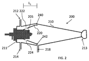
特定の構成において、及び図2を参照して、噴霧チャンバ200の1つの構成が示されている。噴霧チャンバ200は全体として、外側チャンバまたは外側の管210と、内側の管220とを備える。外側チャンバ210は、二重のメイクアップガス入口212、214と、排水管218とを備える。メイクアップガス入口212、214は典型的には、共通のガス源に流体結合されるが、所望される場合、異なる気体を利用する場合もある。必須ではないが、メイクアップガス入口212、214は、入口端部211に隣接して位置決めされるように示されるが、以下に指摘されるように、それらは中心に、または出口端部213に向かって代わりに位置決めされる場合もある。内側の管220は、ネブライザーの先端205に隣接して位置決めされ、液滴が逆流する、及び/または内側の管220上に沈着するのを抑える、または阻止するために、メイクアップガス流を提供するように構成された2つ以上のマイクロチャネル222、224を備える。内側の管220の構成及び位置決めは、外側チャンバ210の内側面をいかなる液滴の沈着からも保護するように作用する領域240、242に層流を提供する。入口212、214を通る噴霧チャンバ200内への気体の投入を介して実現される接線方向のガス流は、特定のサイズの範囲の粒子を選択するように作用する。内側の管220におけるマイクロチャネル222、224はまた、内側の管220の表面を液滴の沈着から保護するために、メイクアップガス入口212、214からのガス流を可能にするようにも設計されている。特定の例において、マイクロチャネル222、224は、同様の方法で構成することができる、例えば同一サイズ及び/または直径を有する場合があるのに対して、他の構成では、マイクロチャネル222、224は、異なるようにサイズが決められる、または異なるように配置される場合もある。一部の例では、少なくとも2つ、3つ、4つ、5つまたはそれ以上の別個のマイクロチャネルが内側の管220内に存在する場合もある。マイクロチャネルの正確なサイズ、形態及び形状は変動する場合もあり、各マイクロチャネルは、同一のサイズ、形態及び形状を有する必要はない。一部の例では、所望される保護作用を提供するために、異なる直径のマイクロチャネルが内側の管長手方向軸L1に沿って異なる半径方向の面に存在する場合もある。
In a particular configuration and with reference to FIG. 2, one configuration of the
特定の実施形態において、噴霧チャンバの正確な寸法は、変動する場合もある。特定の構成では、ネブライザーの先端205から噴霧チャンバ200の端部までの長手方向の長さは、およそ10cmからおよそ15cmまで、例えばおよそ12cmまたは13cmであってよい。外側の管210の直径は、およそ1cmからおよそ5cmまで変動する可能性があり、例えばおよそ3cmまたは4cmであってよい。内側の管220の最大直径は、およそ0.5cmからおよそ4cmまで変動する場合があり、内側の管220の外側面と、外側の管210の内側面との間の距離は、所望される層流速度を提供するように選択することができ、例えばその距離は、およそ0.1cmからおよそ0.75cmであってよい。
In certain embodiments, the exact dimensions of the spray chamber may vary. In certain configurations, the longitudinal length from the
特定の例において、内側の管220は、外側チャンバ210の長手方向軸に沿って概ね拡大する内径を有するように示されているが、本明細書に指摘されるようにこのような寸法の変化は必須ではない。内側の管220の任意の一部は、層流を増強させるために「平坦」である、または長手方向軸L1と概ね平行であってよく、あるいは代替の構成では、内側の管220の任意の一部は、層流を増強させるために、少なくとも一部の長さに関して外側の管210の外側面に対して概ね平行であってよい。外側チャンバの内径は、入口端部211から、出口端部213に向かって特定の地点まで拡大し、その後、出口端部213に向かって縮小することで、外側チャンバ210の内径は、入口端部211においてよりも出口端部213においてより小さくなる。しかしながら以下でより詳細に指摘されるように、外側チャンバ210の内径は、入口端部から、出口端部に向かって一定のままである場合、あるいは入口端部から出口端部に向かって拡大する場合もある。
In certain examples, the
特定の構成において、及び図3を参照して、噴霧チャンバの別の実例が示されている。噴霧チャンバ300は、外側チャンバ310と、内側の管320とを備える。内側の管320の内径は、外側チャンバ310の入口端部312から外側チャンバ310の出口端部314に向かって特定の方向に沿ってほぼ一定である。内側の管の外径は、入口端部312から出口端部314に向かって概ね拡大し、例えば内側の管320の全体の外側形状は円錐形である。内側の管320は、試料がネブライザー305から噴霧チャンバ300内に投入される際の内側の管上での液滴の形成及び/または試料の逆流を阻止するのを助けるために、任意選択で1つまたは複数の内部マイクロチャネル(図示せず)を備える場合がある。外側チャンバ310はまた、同一のまたは異なるガス源に流体結合することができる二重のメイクアップガス入口332、334を備える。気体をメイクアップガス入口332、334を経由して噴霧チャンバ300内に投入させて、接線方向の流れを形成し、ネブライザー305から投入された粒子をエアロゾル化し、その中から特定のサイズの粒子を選択することができる。入口332、334からの気体はまた、内側の管320にある任意のマイクロチャネルを通過することで、内側の管の表面上での液滴の形成の可能性を低下させることもできる。内側の管320を外側チャンバ310に対して好適なやり方で位置決めすることによって層流が提供される場合もある。例えばその最も幅の広い地点における外側チャンバ310は、外側チャンバ310を液滴の形成から保護することができる層流を提供するために、内側の管320の外側面からおよそ0.1−0.75cmであってよい。図示されないが、極めて大きな液滴、100ミクロンを超えるサイズを有するものがチャンバ310から外に排出されることを可能にするために、排水ポートが外側チャンバ310内に存在する場合もある。
Another example of a spray chamber is shown in a particular configuration and with reference to FIG. The
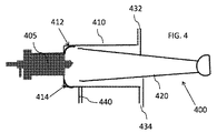
別の実施形態において、及び図4を参照して、噴霧チャンバの別の構成が示されている。噴霧チャンバ400は、外側チャンバ410と、内側の管420とを備える。外側チャンバ410は、外側チャンバ410の入口に隣接する丸められた縁部412、414を備える。いかなる特定の理論によっても拘泥されることは望まないが、丸められた縁部は、外側チャンバ420内での層流の誘導を助け、外側チャンバ420の表面に液滴が蓄積するのを阻止することができる。内側の管420は、入口から出口へと先細になっている。外側の管410は、噴霧チャンバ400内に接線方向の流れを提供するためにメイクアップガス入口432、434を備える。噴霧チャンバ400内に層流を提供するのを助けるために、メイクアップ流れ出口ポート440が存在している。外側チャンバ410は一般に、入口端部から出口端部まで一定の直径を備える。図示されないが、内側の管420は、内側の管420の表面上での液滴の形成の可能性を低下させるために、1つまたは複数の内部マイクロチャネルを備える。
In another embodiment, and with reference to FIG. 4, another configuration of the spray chamber is shown. The
噴霧チャンバの別の構成が、図5A〜図5Eに示されている。図5Aを参照すると、噴霧チャンバは、外側チャンバ502を備える。第1のメイクアップガス入口512は、第2のメイクアップガス入口とは異なる長手方向の面内に位置決めされて示されている(図5Bを参照)。このような構成は、接線方向のガス流の生成を助けることができる。入口512、514は、外側チャンバ502の長手方向軸に概ね直交するように示されているが、それらは、所望される場合、その代わりに角度が付けられる場合もある。図5A〜図5Dに示される構成は、例えば単一粒子−ICP−MS(SP−ICP−MS)、単一細胞−ICP−MS(SC−ICP−MS)及びキャピラリー電気泳動−ICP−MS(CE−ICP−MS)を含め、単一の粒子または単一の細胞を選択するのに、例えば50マイクロリットル未満、または30マイクロリットル未満の少量の流体が使用される低容量の用途において望ましい場合がある。図5A〜図5Dに示される噴霧チャンバの全体の容積は、例えばおよそ6〜12cm3、例えばおよそ7〜11cm3またはおよそ8〜10cm3であってよい。比較の目的のために、図2〜図4に示される噴霧チャンバの容積は、例えば30cm3からおよそ50cm3までであってよい。メイクアップガス入口512、514ならびに噴霧チャンバ500の全体の形状及び寸法は、プラズマまでのエアロゾルの輸送効率を最大限にするのに役立っている。寸法は、軸方向のネブライザーの流れ(または異なる液体試料送達装置からの流れ)が壁を外れることで、エアロゾルの大半がプラズマに直接運ばれるようなやり方で選択される。メイクアップガスの投入のための二重のガス入口の設計は、乱流及び小さい渦に起因してメインのネブライザーの流れから拡散するエアロゾルも含み、かつそれらを壁から離して維持することを助けることができる、例えば液滴の形成/壁の凝結を抑えることができる渦流領域の形成を実現する、または促進することができる。以下に追加される例においてより詳細に指摘されるように、本明細書に記載される噴霧チャンバによって液滴輸送のためのシミュレーションの結果は、90%を超える輸送効率を達成することができることを示している。本明細書で指摘されるように、外側チャンバ502は、層流を促進するために入口端部において丸められた縁部を備えてよい。他の構成では、外側チャンバ502は、排水ポートをさらに備える場合もある(図5Eにおける排水ポート550を参照)。一部の例では、二重のメイクアップガス入口512、514は、外側チャンバ502の入口端部に隣接して位置決めされる。他の例では、二重のメイクアップガス入口512、514は、外側チャンバ502の出口端部に隣接して位置決めされる。図5A〜図5Dに示されるように外側チャンバ502の外径は、長手方向にほぼ一定である。一部の例では、内側の管(図示せず)は、外側チャンバ502の中に位置決めされてよく、この場合、内側の管は、液体試料の液滴が内側の管の表面に沈着するのを阻止するためにメイクアップガスを受容するように各々構成された複数のマイクロチャネルを備える。内側の管は、外側チャンバの内側面上での液滴の形成を阻止するために外側チャンバ502内に層流を提供するように位置決めすることができる。
Another configuration of the spray chamber is shown in FIGS. 5A-5E. With reference to FIG. 5A, the spray chamber comprises an
特定の実施形態において、本明細書に記載される噴霧チャンバは、1つまたは複数の追加の噴霧チャンバと並行して使用することもできる。図6Aを参照すると、第2の噴霧チャンバ620に流体結合された第1の噴霧チャンバ610を示すブロック図が示されている。噴霧チャンバ610、620の各々は、本明細書に記載される噴霧チャンバの1つであってよい、または噴霧チャンバ610、620の一方は、本明細書に記載される噴霧チャンバの1つであってよく、他方の噴霧チャンバは、従来式の複光路噴霧チャンバもしくは従来式のサイクロン式噴霧チャンバである場合もある。いかなる特定の実例によっても拘泥されることは望まないが、二重通路の噴霧チャンバにおいて、より小さいエアロゾル液滴は、中心管へと誘導され、より大きなエアロゾル液滴は、重力によって取り除かれ、排水管を通ってチャンバを出て行く。より小さい液滴を下流のイオン化源へと提供することができる。サイクロン式の噴霧チャンバでは、接線方向のガス流によって生成された渦を利用して、液滴に対して遠心力を与えることができる。より小さい液滴は、そこを出て行くガス流の中に提供されるのに対して、より大きな液滴は、チャンバの内壁に接触し、排水管を通って取り除かれる。一部の例では、噴霧チャンバ610は、二重通路の噴霧チャンバであってよく、噴霧チャンバ620は、本明細書に記載される噴霧チャンバの1つであってよい。他の例では、噴霧チャンバ610は、本明細書に記載される噴霧チャンバの1つであってよく、噴霧チャンバ620は、二重通路の噴霧チャンバである場合もある。追加の構成では、噴霧チャンバ610は、サイクロン式噴霧チャンバであってよく、噴霧チャンバ620は、本明細書に記載される噴霧チャンバの1つであってよい。他の例では、噴霧チャンバ610は、本明細書に記載される噴霧チャンバの1つであってよく、噴霧チャンバ620は、サイクロン式噴霧チャンバである場合もある。一部の構成では、噴霧チャンバ610、620の各々は、本明細書に記載される噴霧チャンバの1つであり得るが、内側の管に存在するマイクロチャネルの寸法は異なる場合がある。他の構成では、噴霧チャンバ610、620の一方は、図2に示される噴霧チャンバであってよく、噴霧チャンバの他方は、図3〜図5Dに示される噴霧チャンバの1つである場合もある。特定の構成では、噴霧チャンバ610、620の一方は、図3に示される噴霧チャンバであってよく、噴霧チャンバの他方は、図2、図4または図5A〜図5Dに示される噴霧チャンバである場合もある。一部の例では、噴霧チャンバ610、620の一方は、図4に示される噴霧チャンバであってよく、噴霧チャンバの他方は、図2、図3または図5A〜図5Dに示される噴霧チャンバである場合もある。図示されないが、所望される場合、3つ以上の噴霧チャンバを互いに流体結合させることもできる。
In certain embodiments, the spray chambers described herein can also be used in parallel with one or more additional spray chambers. Referring to FIG. 6A, a block diagram showing a
特定の例において、本明細書に記載される噴霧チャンバと共に使用するのに適した例示の液体試料送達装置は、限定されるものではないが、ネブライザー、注入器、キャピラリチューブなどを含める。いくつかの実施形態において、ネブライザーは、液体試料を噴霧チャンバの中に投入するために物理的に噴霧チャンバに結合する。ネブライザーは、クロスフローネブライザー、同軸ネブライザー及びマイクロフローネブライザーを含めた多くの形態を取ることができる。注入器が使用される場合、注入器は、小さい開口部を備えた針、キャピラリチューブまたは他の管の形態を取る場合がある。本開示の利点が与えられたと仮定すると、当業者によって、本明細書に記載される噴霧チャンバと共に使用するのに適した追加の液体試料送達装置が選択されるであろう。例えば、超音波パルス液体送達装置、液滴生成器または微小液滴生成器もまた、本明細書に記載される噴霧チャンバと共に使用することができる。加えて、ネブライザー(または他の液体送達装置)を、例えば液体クロマトグラフィー装置、キャピラリー電気泳動装置、細胞選別機、細胞処理装置などの1つまたは複数の上流の装置または器具につなぐこともできる。 In certain examples, exemplary liquid sample delivery devices suitable for use with the spray chambers described herein include, but are not limited to, nebulizers, injectors, capillary tubes, and the like. In some embodiments, the nebulizer physically couples to the spray chamber to charge the liquid sample into the spray chamber. The nebulizer can take many forms, including a cross-flow nebulizer, a coaxial nebulizer and a micro-flow nebulizer. When an injector is used, the injector may take the form of a needle, capillary tube or other tube with a small opening. Given the advantages of the present disclosure, one of ordinary skill in the art would select an additional liquid sample delivery device suitable for use with the spray chambers described herein. For example, an ultrasonic pulsed liquid delivery device, a droplet generator or a microdroplet generator can also be used with the spray chambers described herein. In addition, the nebulizer (or other liquid delivery device) can be connected to one or more upstream devices or instruments such as, for example, a liquid chromatography device, a capillary electrophoresis device, a cell sorter, a cell processing device.
特定の例では、本明細書に記載される噴霧チャンバは、1つまたは複数のイオン化源及び/または検出器と組み合わせて使用することができる。簡素化されたブロック図が図6Bに示されている。システム650は、イオン化源670に流体結合された噴霧チャンバ660を備える。イオン化源670は、イオン化源670によってイオン化される/霧化される種の検出のために検出器680に流体結合される、光学的に結合されるなどの場合がある。イオン化源670の厳密な性質は、変動する場合があり、例示のタイプのイオン化源670には、限定されるものではないが、誘導結合プラズマ、容量結合プラズマ、マイクロ波誘導プラズマ、低流プラズマ、アーク、スパーク、フレーム、及び例えば無機材料または有機材料を含む試料などの試料をイオン化する及び/または霧化することができる他の高温源あるいは高エネルギー源が含まれる。一部の例では、イオン化源670は、限定されるものではないが、電子イオン化、化学イオン化、脱離化学イオン化、負イオン化学イオン化、電場脱離、電場イオン化、高速原子衝撃、二次イオン質量分析法、電気スプレーイオン化、プローブ電気スプレーイオン化、ソニックスプレーイオン化、大気圧化学イオン化、大気圧光イオン化、大気圧レーザイオン化、マトリックス支援レーザー脱離イオン化、エアロゾルレーザ脱離イオン化、表面増強レーザー脱離イオン化、グロー放電、共鳴イオン化、熱イオン化、サーモスプレーイオン化、放射性イオン化、イオン付着イオン化、液体金属イオン化装置、レーザアブレーション電気スプレーイオン化、または任意の2つ以上のこれらの例示のイオン化技術の組み合わせを含めた1つまたは複数の技術を実施することができる供給源として構成されてよい。検出器680は、検出されるべき試料種に応じて多くの形態を採る場合があり、例示の検出器は、光学検出器、粒子検出器、電子検出器及びイオン検出器を含める。
In certain examples, the spray chambers described herein can be used in combination with one or more ion sources and / or detectors. A simplified block diagram is shown in FIG. 6B. The
特定の例では、イオン化源は、1つまたは複数のトーチと、1つまたは複数の誘導装置とを備えてよい。イオン化源の特定の構成要素が図7〜図9に示されている。例示の誘導装置及びトーチは、例えば米国特許第9,433,073号及び第9,360,403号において記載されており、これらの特許の全開示は、全ての目的のために参照により本明細書にこれにより組み込まれている。図7を参照すると、を誘導コイル720と組み合わせてトーチ710を備える装置が示されている。誘導コイル720は典型的には、誘導結合プラズマ750を維持するために、無線周波生成器(図示せず)に電気的に結合されて無線周波エネルギーをトーチ710内に提供する。試料中の種をイオン化する及び/または霧化するために、本明細書に記載される噴霧チャンバを使用してプラズマ750内に試料を噴霧することができる。望まれる場合、噴霧チャンバは、図2〜図4に示されるものと同じように構成することができる、または本明細書に記載されるタンデム型または二重の噴霧チャンバを備える場合もある。典型的な構成では、噴霧チャンバに液体試料を提供するために、ネブライザーが噴霧チャンバに流体結合される。噴霧チャンバは、試料をエアロゾル化し、それをプラズマ750に提供する。光学技術または質量分析技術または他の好適な技術を利用して試料中の金属種(または有機種)をイオン化または霧化し、検出することができる。
In certain examples, the ion source may include one or more torches and one or more induction devices. Specific components of the ion source are shown in FIGS. 7-9. Illustrative guidance devices and torches are described, for example, in US Pat. Nos. 9,433,073 and 9,360,403, and the full disclosure of these patents is herein by reference for all purposes. This is incorporated into the book. With reference to FIG. 7, a device comprising a
代替の一構成において、誘導コイル720は、1つまたは複数の平板電極で置き換えられる場合もある。例えば、及び図8を参照すると、第1の平板電極820及び第2の平板電極821は、トーチ810を収容することができる開口を備えるように示されている。例えばトーチ810は、平板電極820、821を備える誘導装置の一部の領域内に配置させることができる。トーチ810及び平板820、821からの誘導エネルギーを利用して、例えば誘導結合プラズマなどのプラズマまたは他のイオン化源/霧化源850を維持することができる。無線周波生成器830が、平板820、821の各々に電気的に結合されるように示されている。望まれる場合、単一の平板電極のみが代わりに使用される場合もある。試料中の種をイオン化する及び/または霧化するために、本明細書に記載される噴霧チャンバを使用してプラズマ850内に試料を噴霧することができる。望まれる場合、図8の構成要素と共に使用される噴霧チャンバは、図2〜図4に示されるものと同じように構成することができる、または本明細書に記載されるタンデム型または二重の噴霧チャンバを備える場合もある。典型的な構成では、噴霧チャンバに液体試料を提供するために、ネブライザーが噴霧チャンバに流体結合される。噴霧チャンバは、試料をエアロゾル化し、それをプラズマ850に提供する。光学技術または質量分析技術または他の好適な技術を利用して試料中の金属種(または有機種)をイオン化または霧化し、検出することができる。
In one alternative configuration, the
他の構成では、1つまたは複数の放射状のフィンを備える誘導装置が、本明細書に記載される噴霧チャンバと組み合わせて代わりに使用される場合もある。図9を参照すると、装置またはシステムは、少なくとも1つの放射状のフィンを備える誘導コイル920と、トーチ910とを備えてよい。トーチ910及び放射状にフィンの付いた誘導コイル920からの誘導エネルギーを利用して、例えば誘導結合プラズマなどのプラズマまたは他のイオン化源/霧化源(図示せず)を維持することができる。トーチ910内に無線周波エネルギーを提供するために、無線周波生成器(図示せず)を誘導装置920に電気的に結合させることができる。図9の構成要素と共に使用される噴霧チャンバは、図2〜図4に示されるものと同じように構成することができる、または本明細書に記載されるタンデム型または二重の噴霧チャンバを備える場合もある。典型的な構成では、噴霧チャンバに液体試料を提供するために、ネブライザーが噴霧チャンバに流体結合される。噴霧チャンバは、試料をエアロゾル化し、それをプラズマ950に提供する。光学技術または質量分析技術または他の好適な技術を利用して試料中の金属種(または有機種)をイオン化または霧化し、検出することができる。
In other configurations, a guidance device with one or more radial fins may be used instead in combination with the spray chambers described herein. With reference to FIG. 9, the device or system may include an
他の例では、1つまたは複数の容量性装置、例えば容量性コイルまたは容量性プレートが、本明細書に記載される噴霧チャンバと組み合わせて使用される場合もある。さらに、プラズマまたはフレームなどの霧化/イオン化源を維持するためにトーチ内にエネルギーを提供することができる2つ以上の誘導装置、容量性装置または他の装置が、本明細書に記載される噴霧チャンバと組み合わせて使用される場合もある。 In other examples, one or more capacitive devices, such as capacitive coils or capacitive plates, may be used in combination with the spray chambers described herein. In addition, two or more induction devices, capacitive devices or other devices that can provide energy within the torch to maintain an atomization / ionization source such as plasma or frame are described herein. It may also be used in combination with a spray chamber.
特定の構成では、本明細書に記載される噴霧チャンバは、質量分析法(MS)を実施するように構成されたシステムの中で使用される場合もある。例えば、及び図10を参照すると、MSデバイスまたはシステム1000は、噴霧チャンバ1010と、例えばプラズマなどの霧化源/イオン化源を維持するために使用することができるトーチ及び誘導装置などのイオン化装置1020と、質量分析計1030と、検出器または検出装置1040と、プロセッサまたは処理装置1050と、ディスプレイ1060とを含む。噴霧チャンバ1010、イオン化装置1020、イオン化装置1020、質量分析計1030及び検出装置1040は、1つまたは複数の真空ポンプを用いて低下した圧力で作動されてよい。しかしながら特定の例では、質量分析計1030及び検出装置1040のみが低下した圧力で作動される場合もある。図示されないが、噴霧チャンバ1010は典型的には、噴霧チャンバ1010内に液体試料を投入するために、ネブライザー、注入器または他の装置に流体結合される。イオン化装置1020は、図7から図9に例示されるような1つまたは複数の構成要素を備える、あるいはイオン化源を提供する、または維持することができる他の装置及び構成要素を備える場合もある。質量分析計1030は、概ね試料の性質、所望される分解能などに応じて多くの形態を採る場合があり、例示の質量分析計は、1つまたは複数のロッド組立体、例えば四重極または他のロッド組立体を備えてよい。一部の例では、質量分析計1030は、飛行時間装置であってよい、または飛行時間装置を含む場合もある。一部の例では、質量分析計1030は、その固有の無線周波生成器を備えてよい。検出装置1040は、電子増倍管、ファラデーカップ、コーティングされた写真乾板、シンチレーション検出器、マルチチャネルプレートなど、及び本開示の利点が与えられたと仮定すると、当業者によって選択される他の好適な装置などの既存の質量分析計と共に使用され得る任意の好適な検出装置であってよい。処理装置1050は典型的には、マイクロプロセッサ及び/またはコンピュータ、ならびにMSデバイス1000に投入された試料の分析のために好適なソフトウェアを含む。MSデバイス1000内に投入された種の化学的同一性の決定のために1つまたは複数のデータベースが処理装置1050によってアクセスされてよい。限定されるものではないが、例えばPerkinElmer Health Sciences社より商業的に入手可能なAS−90プラス及びAS−93プラス自動試料採取器などの当分野に既知の他の好適な追加の装置がMSデバイス1000と共に使用される場合もある。また、本開示の利点が与えられた仮定すると、既存のMSデバイスを本明細書に記載される噴霧チャンバに後付けすること、及び本明細書に記載される噴霧チャンバを利用して新たなMSデバイスを設計することも当業者の能力の範囲内である。
In certain configurations, the spray chambers described herein may also be used in systems configured to perform mass spectrometry (MS). For example, and with reference to FIG. 10, the MS device or
特定の構成において、本明細書に記載される噴霧チャンバは、原子吸光分析計(OES)において使用することができる。図11を参照すると、OES装置またはシステム1100は、噴霧チャンバ1110と、イオン化装置1120と、検出装置1130とを含む。噴霧チャンバ1110は、ネブライザーに流体結合され、イオン化装置1120に投入するために液体試料をエアロゾル化してよい。イオン化装置1120は、図7〜図9に例示されるような1つまたは複数の構成要素、またはイオン化源を提供する、もしくは維持することができる他の装置及び構成要素を備えてよい。検出器または検出装置1130は、多くの形態を取る場合があり、光学放射1125などの光学放射を検出し得る任意の好適な装置であってよい。例えば検出装置1130は、レンズ、ミラー、プリズム、窓、バンドパスフィルタなどの好適な光学装置を含んでよい。検出装置1130はまた、マルチチャネルOES装置を提供するために、例えばエシェル格子などの格子を含む場合もある。エシェル格子などの格子は、多数の放射波長の同時検出を可能にし得る。格子は、モノクロメータ、またはモニターするための1つまたは複数の特定の波長の選択のための他の好適な装置の中に位置決めされてよい。特定の例では、検出装置1130は、電荷結合素子(CCD)を含んでよい。他の例では、OES装置1100は、多数の放射波長の同時検出を行うために、フーリエ変換を実施するように構成されてよい。検出装置1130は、限定されるものではないが、紫外線、可視線、近赤外線または遠赤外線などを含めた広い波長範囲にわたって放射波長をモニターするように構成されてよい。OES装置1100は、マイクロプロセッサ及び/またはコンピュータなどの好適な電子機器、及び所望される信号を提供するため、及び/またはデータ取得のために好適な回路をさらに含んでよい。好適な追加の装置及び回路は、当分野で知られており、またPerkinElmer Health Sciences社より商業的に入手可能なOptima2100DVシリーズ、Optima5000DVシリーズOES装置またはOptima8000もしくは8300シリーズOES装置などの商業的に入手可能なOES装置において見い出すことができる。任意選択の増幅器1140、例えば光電子増倍管は、信号1135を増大させる、例えば検出された光子からの信号を増幅するように作用可能であってよく、ディスプレイ1150に信号を提供し、このディスプレイは表示器、コンピュータなどであってよい。信号1135が表示または検出のために十分に大きな例では、増幅器1140は省略される場合もある。特定の例では、増幅器1140は、検出装置1130から信号を受信するように構成された光電子増倍管(PMT)である。しかしながら本開示の利点が与えられた仮定すると、当業者によって信号を増幅するための他の好適な装置が選択されるであろう。所望される場合、PMTを検出器1130に統合することができる。本開示の利点が与えられた仮定すると、既存のOES装置を本明細書に記載される噴霧チャンバに後付けすること、及び本明細書に記載される噴霧チャンバを用いて新たなOES装置を設計することも当業者の能力の範囲内である。OES装置は、例えばPerkinElmer Health Sciences社より商業的に入手可能なAS90及びAS93自動試料採取器、または他の供給元から入手可能な同様の装置などの自動試料採取器をさらに含む場合もある。
In certain configurations, the spray chambers described herein can be used in atomic absorption spectrometers (OESs). With reference to FIG. 11, the OES device or
特定の例では、本明細書に記載される噴霧チャンバは、原子吸光分析計(AAS)において使用することができる。図12を参照すると、単一のビームAAS1200は、電源1210と、ランプ1220と、噴霧チャンバ1225と、イオン化装置1230と、検出器または検出装置1240と、任意選択の増幅器1250と、ディスプレイ1260とを備える。電源1210は、ランプ1220に電力を供給するように構成されてよく、このランプは、原子及びイオンによる吸収のために1つまたは複数の光の波長1222を提供する。好適なランプには、限定されるものではないが、水銀ランプ、陰極線ランプ、レーザなどが含まれる。ランプは、好適なチョッパーまたはパルス電源供給部を利用してパルス式にさせられる、またはレーザが実装される例では、レーザが、例えば5回、10回または20回/秒などの選択された周波数でパルス式にされる場合もある。ランプ1220の正確な構成は変動する場合がある。例えばランプ1220は、イオン化装置1230のトーチに沿って軸方向に光を提供してよい、またはイオン化装置1230のトーチに沿って半径方向に光を提供する場合もある。図12に示される例は、ランプ1220からの光の軸方向の供給のために構成されている。信号の軸方向の観測を利用する信号対雑音の利点が存在し得る。イオン化装置1230は、図7〜図9に例示されるような1つまたは複数の構成要素、またはイオン化源を提供する、もしくは維持することができる他の装置及び構成要素を備えてよい。試料がイオン化装置1230内で霧化される及び/またはイオン化される際、ランプ1220からの入射光1222は、原子を励起し得る。すなわちランプ1220によって供給される光1222の任意の割合は、イオン化装置1230において原子及びイオンによって吸収されてよい。残りの割合の光1235が、検出装置1240に伝達されてよい。検出装置1240は、例えばプリズム、レンズ、格子、及び、例えばOES装置を参照して上記で考察したものなど他の好適な装置を利用して1つまたは複数の好適な波長を提供してよい。ディスプレイ1260に提供される信号を増大させるために、信号は任意選択の増幅器1250に提供されてよい。イオン化装置1230内での試料による吸収の量を考慮に入れるために、100%の透過率の基準値を提供するために、水などの素材が試料投入の前に投入される場合がある。試料がイオン化装置1230に投入される際に伝達される光の量が測定されてよく、透過率を獲得するために、試料と共に伝達される光の量を基準値で割ることができる。透過率の負のlog10は、吸収に匹敵する。AAS装置1200は、マイクロプロセッサ及び/またはコンピュータなどの好適な電子機器と、所望される信号を提供するため、及び/またはデータ取得のために好適な回路とをさらに含む。好適な追加の装置及び回路は、例えばAAnalystシリーズ分光計またはPinAAcle分光計などの商業的に入手可能なAAS装置に見い出される場合がある。また、本開示の利点が与えられた仮定すると、既存のAAS装置を本明細書に記載される噴霧チャンバに後付けすること、及び本明細書に記載される噴霧チャンバを利用して新たなAAS装置を設計することも当業者の能力の範囲内である。AAS装置は、例えばPerkinElmer Health Sciences社より商業的に入手可能なAS−90A、AS−90プラス及びAS−93プラス自動試料採取装置など当分野で既知の自動試料送達装置をさらに含む場合もある。イオン化装置1230が、誘導結合プラズマを維持するように構成される場合、誘導装置に電気的に結合された無線周波生成器が存在する場合もある。特定の実施形態において、単一ビームAAS装置の代わりに、二重ビームAAS装置が代わりに使用される場合もある。
In certain examples, the spray chambers described herein can be used in atomic absorption spectrometers (AAS). Referring to FIG. 12, a single beam AAS1200 includes a
特定の構成では、噴霧チャンバの内側の管は、ガス流が内側の管の外側面から内側の管の内側面まで流れる、またはその逆に流れる、またはその両方に流れることを許可する1つまたは複数のマイクロチャネルを備えてよい。1つの構成の断面図が図13に示されている。内側の管1300は、入口端部1302と、出口端部1304とを備える。マイクロチャネル1312、1314は、入口端部1302により近づけて位置決めされるように示されているが、この構成は必須ではない。マイクロチャネル1312、1314は、ほぼ同一の半径方向の面内に位置決めされるが、それらは、望まれる場合互いからずらされる場合もある。例えばマイクロチャネル1312、1314の一方が、内側の管1300の長手方向において出口端部1304により近づけて位置決めされる場合もある。加えて、マイクロチャネル1312、1314の形状、配向及び/または直径は、同一である必要はない。異なるようにサイズが決められたマイクロチャネルの1つの実例が図14に示されている。内側の管1400は、内側の管1400の長手方向軸にほぼ直交して位置決めされた第1のマイクロチャネル1412と、内側の管1400の長手方向軸に対して特定の角度で位置決めされた第2のマイクロチャネル1414とを備える。加えて、マイクロチャネル1414の直径は、マイクロチャネル1412の直径より大きい。一部の例では、複数の個々のマイクロチャネルが、内側の管の長手方向に沿って位置決めされる場合もある。図15を参照すると、複数のマイクロチャネル1512〜1522を備える内側の管1500が示されている。
In certain configurations, the inner tube of the spray chamber allows the gas flow to flow from the outer surface of the inner tube to the inner surface of the inner tube, vice versa, or both. It may have a plurality of microchannels. A cross-sectional view of one configuration is shown in FIG. The
特定の実施形態において、本明細書に記載される噴霧チャンバは、単一粒子、単一分子または単一細胞を測定するために、誘導結合プラズマ質量分析計と組み合わせて使用される場合もある。例えば、細胞集団における金属レベルを測定するのではなく、単一細胞における1つまたは複数の金属のレベルを測定することが望まれる場合がある。本明細書に記載される噴霧チャンバは、細胞集団から単一の細胞を選択し、単一の選択した細胞をプラズマ内に噴霧するのに使用することができる。一部の例では、この単一の細胞の選択は、固有の金属の研究、溶解した(イオン化した)金属及びナノ粒子金属の取り込み、キレート金属もしくは複合金属、またはイオン形態もしくは複合形態で細胞内に存在する他の金属の取り込みを可能にする。単一分子または単一細胞をプラズマに対して完全な状態で送達することができ、プラズマが、例えば質量分析計、発光分光分析計または原子吸光分析計を利用して、分析のために細胞内の任意の金属をイオン化することができる。細胞のイオン化は、イオンのバーストを生じさせることができ、結果として生じる信号の強度は、粒子のサイズ、及び粒子濃度に関連するパルスの数に概ね比例している。単一粒子の検出が達成され、多数の異なる粒子が集計され得ることを保証するために、迅速で継続的な測定を実施することができる。例示の単一粒子の誘導結合プラズマ方法は、Hineman A.,Stephan C.J.Anal.At.Spectrom.2014、29、152によって説明される。 In certain embodiments, the spray chambers described herein may also be used in combination with an inductively coupled plasma mass spectrometer to measure single particles, single molecules or single cells. For example, it may be desirable to measure the level of one or more metals in a single cell rather than measuring the level of metal in a cell population. The spray chambers described herein can be used to select a single cell from a cell population and spray the single selected cell into the plasma. In some examples, this single cell selection is the study of unique metals, the uptake of lysed (ionized) and nanoparticle metals, chelated or composite metals, or intracellular in ionic or composite forms. Allows the uptake of other metals present in. A single molecule or single cell can be delivered to the plasma in perfect condition, where the plasma is intracellular for analysis, for example using a mass spectrometer, an emission spectrometer or an atomic absorption spectrometer. Any metal can be ionized. Cellular ionization can result in bursts of ions, and the resulting signal intensity is approximately proportional to the number of pulses associated with particle size and particle concentration. Rapid and continuous measurements can be performed to ensure that single particle detection is achieved and a large number of different particles can be aggregated. An exemplary single particle inductively coupled plasma method is described in Hineman A. et al. , Stephan C.I. J. Anal. At. Spectron. Explained by 2014, 29, 152.
特定の例では、使用される細胞の厳密な性質は、動物細胞、植物細胞、藻類細胞、カビ細胞、細菌細胞、ウイルスまたは他の細胞から変わる場合がある。一部の例では、細胞は、例えばヒトの細胞などの哺乳類の細胞、または哺乳類細胞由来の細胞であってよい。一部の例では、哺乳類の細胞は、内胚葉、外胚葉または中胚葉始原細胞由来のものなどの細胞であってよい。例えば哺乳類の細胞は、内胚葉由来の細胞の1つまたは複数であってよく、限定されるものではないが、だ液腺粘液細胞、だ液腺番号1、舌にあるフォン・エブネル腺細胞、乳房腺細胞、涙腺細胞、耳にある耳道腺細胞、エクリン腺暗細胞、エクリン腺明細胞、アポクリン汗腺細胞、まぶたにあるMoll腺細胞、皮脂腺細胞、鼻にあるボーマン腺細胞、十二指腸にあるブルンナー腺細胞、精嚢細胞、前立腺細胞、尿道球腺細胞、バルトリン腺細胞、リトレ腺細胞、子宮内膜細胞、呼吸器官及び消化管の切り離されたゴブレット細胞、胃の内壁の粘液細胞、胃腺酸素原細胞、胃腺分泌細胞、膵腺房細胞、小腸のパネート細胞、肺のタイプII肺細胞、肺のクラブ細胞、脳下垂体前葉細胞(成長ホルモン産生細胞、プロラクチン産生細胞、甲状腺刺激ホルモン、生殖腺刺激ホルモン産生細胞、副腎皮質刺激ホルモン産生細胞)、脳下垂体中葉細胞、分泌性メラニン細胞−刺激ホルモン、大形細胞神経細胞(非分泌性オキシトシン細胞、分泌性バソプレッシン細胞)、(胃より下の)消化管及び気道細胞(分泌性セロトニン細胞、分泌性エンドルフィン細胞、分泌性ソマトスタチン細胞、分泌性ガストリン細胞、分泌性セクレチン細胞、非分泌性コレシストキニン細胞、分泌性インシュリン細胞、分泌性グルカゴン細胞、非分泌性ボンベシン細胞)、甲状腺細胞(甲状腺上皮細胞、傍濾胞細胞)、副甲状腺細胞(上皮小体主細胞、好酸素性細胞)、副じん細胞(クロム親和細胞、分泌性ステロイドホルモン(ミネラルコルチコイド及びグルココルチコイド))、こう丸分泌性テストステロンのライディヒ細胞、卵胞分泌性エストロゲンの内莢膜細胞、破裂した卵巣卵分泌性プロゲステロンの黄体細胞(顆粒膜黄体細胞、卵胞膜黄体細胞)、傍糸球体細胞(レニン分泌)、腎臓の密集斑細胞、腎臓の周極細胞、腎臓の糸球体間質細胞、アルファ細胞(分泌性グルカゴン)、ベータ細胞(分泌性インシュリン及びアミリン)、デルタ細胞(分泌性ソマトスタチン)、PP細胞(ガンマ細胞)(分泌性の膵臓のポリペプチド)またはイプシロン細胞(分泌性グレリン)などのすい島(ランゲルハンス島)が含まれる。他の例では、細胞は、外胚葉由来の細胞の1つまたは複数であってよく、限定されるものではないが、角化した上皮細胞(表皮角化細胞(分化表皮細胞)、表皮基底細胞(幹細胞)、指の爪及び足の爪のケラチン生成細胞、爪床基底細胞(幹細胞)、毛髄質毛幹細胞、毛皮質毛幹細胞、毛小皮毛幹細胞、毛小皮毛根鞘細胞、ハックスリー層の毛根鞘細胞、ヘンレ層の毛根鞘細胞、外側毛根鞘細胞、毛髪マトリクス細胞(幹細胞))、湿性重層化障壁上皮細胞(角膜、舌、口腔、食道、肛門管、遠位尿道及び膣の重層扁平上皮の表面上皮細胞、角膜、舌、口腔、食道、肛門管、遠位尿道及び膣の上皮の基底細胞(幹細胞)、泌尿器の上皮細胞(膀胱の内壁及び尿管))、神経細胞または支持神経組織細胞、感覚変換細胞(コルチ器官の聴覚内有毛細胞、コルチ器官の聴覚外有毛細胞、嗅上皮の基底細胞(嗅覚ニューロンのための幹細胞)、低温感受性一次感覚ニューロン、感熱性の一次感覚ニューロン、表皮のメルケル細胞(触覚センサ)、嗅覚受容体ニューロン、痛みを感じる一次感覚ニューロン(種々のタイプ)、目の中のレチンの光受容体細胞:光受容体棒細胞、目の光受容体の青を感じる円錐細胞、目の光受容体の緑を感じる円錐細胞、目の光受容体の赤を感じる円錐細胞、自己受容一次感覚ニューロン(種々のタイプ)、接触を感じる一次感覚ニューロン(種々のタイプ)、タイプI頚動脈小体細胞(血液pHセンサ)、タイプII頚動脈小体細胞(血液pHセンサ)、耳の前庭器官のタイプI有毛細胞(加速及び重力)、耳の前庭器官のタイプII有毛細胞(加速及び重力)、タイプI味覚芽細胞)、自律神経ニューロン細胞( コリン作動性神経細胞(種々のタイプ)、アドレナリン作動性神経細胞(種々のタイプ)、ペプチド作動性神経細胞(種々のタイプ))、感覚器官及び末梢神経支持細胞(コルチ器官の内柱細胞、コルチ器官の外柱細胞、コルチ器官の内部の支持細胞(phalangeal cell)、コルチ器官の外部の支持細胞、コルチ器官の境界細胞、コルチ器官のヘンゼン細胞、前庭器官支持細胞、味覚芽細胞支持細胞、嗅上皮支持細胞、シェヴァン細胞、衛星グリア細胞(末梢神経細胞体を保護する)、腸のグリア細胞)、ニューロン細胞(介在ニューロン、かご細胞、星細胞、ゴルジ細胞、顆粒細胞、ルガロ細胞、単極性刷子細胞、マルティノッティ細胞、シャンデリア細胞、中型有棘神経細胞、カハールレチウス細胞、ダブルブーケ細胞、ニューログリアフォーム細胞脊髄介在ニューロンレンショー細胞、主細胞紡錘形神経細胞、錐体細胞場所細胞格子細胞、スピード細胞、頭方位細胞、ベッツ細胞、星細胞境界細胞、神経膠星状細胞(種々のタイプ)、乏突起神経膠芽細胞、上衣細胞タニサイト、水晶体細胞、前水晶体上皮細胞及び水晶体繊維細胞を含む結晶質)などの中枢神経系ニューロン及びグリア細胞が含まれる。追加の例では、細胞は、中胚葉由来の細胞の1つまたは複数であってよく、限定されるものではないが、含脂肪細胞、白色脂肪細胞、褐色脂肪細胞、肝臓脂肪細胞、障壁機能細胞(肺、(胃より下の)消化管、外分泌腺及び尿生殖路)、腎臓細胞、腎臓壁細胞、腎糸球体有足細胞、腎臓近位細管刷子縁細胞、ヘンレ係蹄の薄いセグメント細胞、腎臓の遠位細管細胞、腎臓の集合管細胞主細胞、介在細胞、タイプI肺細胞(肺細胞の内壁の空気層)、膵臓の導管細胞(房心細胞)、無紋導管細胞(汗腺、だ液腺、乳腺などの)、主細胞介在細胞、導管細胞(精嚢、前立腺などの)、腸の刷子縁細胞(微柔毛を有する)、外分泌腺線条体の導管細胞、胆嚢上皮細胞、小管導出性非線毛性細胞、精巣上体の主細胞、精巣上体基底細胞、内皮細胞、エナメル芽細胞上皮細胞(歯のエナメル質分泌)、耳の前庭系の半月面上皮細胞(プロテカグリオン分泌)、コルチ器官歯間上皮細胞(毛髪細胞を覆う分泌性天蓋膜)、疎性結合組織線維母細胞、角膜線維芽細胞(角膜実質細胞)、腱線維芽細胞、骨髄細網組識線維芽細胞、他の非上皮線維芽細胞、周細胞、椎間板の髄核細胞、セメント芽細胞/セメント細胞(歯根の骨様のイワン細胞分泌)、歯牙母細胞/歯牙細胞(歯の象牙質分泌)、ヒアリン軟骨細胞、線維軟骨細胞、弾性軟骨細胞、骨芽細胞/骨細胞、骨幹細胞(骨芽細胞の幹細胞)、目のガラス体の硝子体細胞、耳の外リンパ腔の星細胞、肝星細胞(伊東細胞)、膵臓星状細胞、骨格筋細胞、赤色骨格筋細胞、白色骨格筋細胞、介在骨格筋細胞、筋紡錘の核袋細胞、筋紡錘の核鎖細胞、衛星細胞(幹細胞)、心筋細胞、通常の心筋細胞、結節点の心筋細胞、プルキンエ繊維細胞、平滑筋細胞(種々のタイプ)、虹彩の筋上皮細胞、外分泌腺の筋上皮細胞、赤血球(赤血球)、巨大核細胞(血小板前駆細胞)、単球(白血球)、結合組織マクロファージ(種々のタイプ)、表皮ランゲルハンス細胞、破骨細胞(骨内)、樹状細胞(リンパ系組織内)、小グリア細胞(中枢神経系内)、好中性顆粒球、エオシン好性顆粒球、好塩基性顆粒球、ハイブリドーマ細胞、肥満細胞、ヘルパーT細胞、サプレッサーT細胞、細胞傷害性T細胞、ナチュラルキラーT細胞、B細胞、ナチュラルキラー細胞、網状赤血球、血液及び免疫系に関する幹細胞及び関係する原種(種々のタイプ)、生殖細胞、卵原細胞/卵母細胞、精子細胞、精母細胞、精原細胞(精母細胞に関する幹細胞)、精子、ナース細胞、卵胞細胞、セルトリ細胞(睾丸内の)、胸腺上皮細胞、間質性細胞または間質性腎細胞が含まれる。
In certain examples, the exact properties of the cells used may vary from animal cells, plant cells, algal cells, mold cells, bacterial cells, viruses or other cells. In some examples, the cell may be a mammalian cell, such as a human cell, or a cell derived from a mammalian cell. In some examples, mammalian cells may be cells such as those derived from endoderm, ectoderm or mesoderm primordial cells. For example, mammalian cells may be one or more endoblast-derived cells, including, but not limited to, secretory mucus cells,
特定の例では、本明細書に記載される噴霧チャンバは、単一細胞内の無機種及び/または有機種を選択し、分析するために使用することができる。例えば、細胞集団を噴霧チャンバ内に投入することができ、噴霧チャンバを使用して、投入された細胞集団から単一の細胞を選択することができる。選択された細胞は、イオン化装置の中に噴霧されて、噴霧され選択された単一細胞における無機種または有機種をイオン化/霧化することができる。噴霧され選択された単一細胞における少なくとも1つの無機種または有機種を検出することができる。本明細書で指摘されるように、選択された細胞は動物細胞、植物細胞、藻類細胞、カビ細胞、細菌細胞、ウイルスまたは他の細胞を含めた多くの異なるタイプであってよい。一部の例では、細胞集団から選択された細胞は、内胚葉、外胚葉または中胚葉由来の哺乳類の細胞である。他の例では、選択された単一細胞における少なくとも1つの金属種が検出される。一部の例では、選択された単一細胞における少なくとも1つのアミノ酸、ペプチドまたはタンパク質が検出される。他の例では、選択された単一細胞における少なくとも1つの脂質、脂肪酸、脂肪などが検出される。一部の例では、選択された単一細胞における少なくとも1つの単糖類、二糖類、多糖類または炭水化物が検出される。他の例では、選択された単一細胞における少なくともヌクレオチド、核酸、例えばデオキシリボ核酸、リボ核酸などが検出される。他の例では、選択された単一細胞によって取り込まれた外部物質のレベル、例えば抗癌剤、ステロイドまたは他の薬剤もしくは生体物質のレベルが検出される。一部の例では、選択された単一細胞に結びついた、またはそれに関連付けられた、例えばモノクロナール抗体などの生体物質の有無が検出される。 In certain examples, the spray chambers described herein can be used to select and analyze inorganic and / or organic species within a single cell. For example, a cell population can be populated into a spray chamber, and the spray chamber can be used to select a single cell from the populated cell population. The selected cells can be sprayed into an ionizer to ionize / atomize the inorganic or organic species in the sprayed and selected single cells. At least one inorganic or organic species in the sprayed and selected single cells can be detected. As pointed out herein, the selected cells can be of many different types, including animal cells, plant cells, algal cells, mold cells, bacterial cells, viruses or other cells. In some examples, the cells selected from the cell population are mammalian cells from endoderm, ectoderm or mesoderm. In another example, at least one metal species in the selected single cell is detected. In some examples, at least one amino acid, peptide or protein in selected single cells is detected. In another example, at least one lipid, fatty acid, fat, etc. in the selected single cell is detected. In some examples, at least one monosaccharide, disaccharide, polysaccharide or carbohydrate is detected in the selected single cell. In another example, at least nucleotides, nucleic acids, such as deoxyribonucleic acid, ribonucleic acid, etc., are detected in selected single cells. In other examples, levels of external substances taken up by selected single cells, such as levels of anti-cancer agents, steroids or other agents or biomaterials, are detected. In some examples, the presence or absence of biological material associated with or associated with selected single cells, such as monoclonal antibodies, is detected.
他の例において、方法は、1つまたは複数の本明細書に記載される噴霧チャンバを提供することと、細胞集団から単一細胞を選択するため、及びイオン化装置を利用して選択された単一細胞内の少なくとも1つの無機種または有機種を検出するために、提供された噴霧チャンバを利用するための説明を提供することとを含む。例えば方法は、選択された単一細胞内の少なくとも1つの無機種または有機種を検出するために、誘導結合プラズマ質量分析計と共に噴霧チャンバを利用するための説明を提供することを含む。一部の例では、方法は、選択された単一細胞内の少なくとも1つの無機種または有機種を検出するために、誘導結合発光分光分析計と共に噴霧チャンバを利用するための説明を提供することを含む。他の例では、方法は選択された単一細胞内の少なくとも1つの無機種または有機種を検出するために、誘導結合原子吸光分析計によって噴霧チャンバを利用するための説明を提供することを含む。一部の例では、方法は、単一の哺乳類の細胞を選択するために、哺乳類の細胞集団を利用するための説明を提供することを含む。 In another example, the method is simply to provide one or more of the spray chambers described herein, to select a single cell from the cell population, and to utilize an ionizer. To provide an explanation for utilizing the provided spray chamber to detect at least one inorganic or organic species within a cell. For example, the method comprises providing an explanation for utilizing an inductively coupled plasma mass spectrometer and a spray chamber to detect at least one inorganic or organic species within a selected single cell. In some examples, the method provides an explanation for utilizing a spray chamber with an inductively coupled luminescence spectrometer to detect at least one inorganic or organic species within a selected single cell. including. In another example, the method comprises providing an explanation for utilizing a spray chamber by an inductively coupled atomic absorption spectrometer to detect at least one inorganic or organic species within a selected single cell. .. In some examples, the method comprises providing an explanation for utilizing a mammalian cell population to select a single mammalian cell.
本明細書に記載される噴霧チャンバの構成要素及び態様の一部を例示するために特定の特有の例が、以下に記載される。 Specific specific examples are described below to illustrate some of the components and embodiments of the spray chamber described herein.
実施例1
図2に示されるものと同様の噴霧チャンバが図16に示されている。種々の構成要素の寸法は、図16に設けられた矢印を用いて示されている。寸法1610はおよそ1.5cmであり、寸法1620はおよそ3cmであり、寸法1630はおよそ13cmであり、寸法1640はおよそ1.5cmであり、寸法1650はおよそ2.2cmであり、寸法1660はおよそ1cmである。噴霧チャンバ1600は、二重のメイクアップガス入口1602、1604と、複数のマイクロチャネルを備えた内側の管とを有する。二重のメイクアップガス入口は、噴霧チャンバ1600内に接線方向のガス流を提供するためにメイクアップガス源(図示せず)と流体結合される。噴霧チャンバ1600内にしかるべく内側の管を位置決めすることによって層流が形成される。層流は、外側の管または外側チャンバを液滴の沈着から保護するように作用する。内側の管のマイクロチャネルを通るガス流は、内側の管上での液滴の形成を阻止するように作用する。合わさったガス流を使用して、試料から単一の粒子または単一の細胞を選択することができる。
Example 1
A spray chamber similar to that shown in FIG. 2 is shown in FIG. The dimensions of the various components are shown using the arrows provided in FIG.
実施例2
図3に示されるものと同様の噴霧チャンバが図17に示されている。種々の構成要素の寸法は、図17に設けられた矢印を用いて示されている。寸法1710はおよそ1.5cmであり、寸法1720はおよそ3cmであり、寸法1730はおよそ2.5cmであり、寸法1740はおよそ11cmであり、寸法1750はおよそ1.5cmであり、寸法1760はおよそ1.5cmである。噴霧チャンバ1700は、二重のメイクアップガス入口1702、1704と、複数のマイクロチャネルを備えた内側の管とを有する。二重のメイクアップガス入口は、噴霧チャンバ1700内に接線方向のガス流を提供するためにメイクアップガス源(図示せず)と流体結合される。噴霧チャンバ1700内にしかるべく内側の管を位置決めすることによって層流が形成される。層流は、外側の管または外側チャンバを液滴の沈着から保護するように作用する。内側の管のマイクロチャネルを通るガス流は、内側の管上での液滴の形成を阻止するように作用する。合わさったガス流を使用して、試料から単一の粒子または単一の細胞を選択することができる。
Example 2
A spray chamber similar to that shown in FIG. 3 is shown in FIG. The dimensions of the various components are shown using the arrows provided in FIG.
実施例3
図4に示されるものと同様の噴霧チャンバが図18に示されている。種々の構成要素の寸法は、図18に設けられた矢印を用いて示されている。寸法1810はおよそ3cmであり、寸法1820はおよそ2.5cmであり、寸法1830はおよそ13.5cmであり、寸法1840はおよそ1cmであり、寸法1850はおよそ3.2cmである。噴霧チャンバ1800は、二重のメイクアップガス入口1802、1804と、複数のマイクロチャネルを備えた内側の管とを有する。二重のメイクアップガス入口は、噴霧チャンバ1800内に接線方向のガス流を提供するためにメイクアップガス源(図示せず)と流体結合される。噴霧チャンバ1800内にしかるべく内側の管を位置決めすることによって層流が形成される。層流は、外側の管または外側チャンバを液滴の沈着から保護するように作用する。内側の管のマイクロチャネルを通るガス流は、内側の管上での液滴の形成を阻止するように作用する。合わさったガス流を使用して、試料から単一の粒子または単一の細胞を選択することができる。
Example 3
A spray chamber similar to that shown in FIG. 4 is shown in FIG. The dimensions of the various components are shown using the arrows provided in FIG.
実施例4
本明細書に記載される噴霧チャンバに流体結合されたネブライザーを介して細胞懸濁液を投入することによって細胞懸濁液を霧状にすることができる。噴霧チャンバは、個々の細胞を選択し、それらを誘導結合プラズマに提供することができる。各々の細胞がプラズマに進入する際、それはイオン化され、固有の金属種から結果として生じるイオンバーストが質量分析計によって検出される。各々の細胞は、個々の粒子として同じように扱われる。細胞の濃度は、同時発生を最少限にする、すなわち細胞が同時にプラズマに提供される状況を最少限にするために100,000細胞/mL前後であることが望ましい場合がある。
Example 4
The cell suspension can be atomized by pouring the cell suspension into the spray chamber described herein via a fluid-bound nebulizer. The spray chamber can select individual cells and provide them for inductively coupled plasma. As each cell enters the plasma, it is ionized and the resulting ion burst from the unique metal species is detected by the mass spectrometer. Each cell is treated the same as an individual particle. It may be desirable for the cell concentration to be around 100,000 cells / mL in order to minimize co-occurrence, i.e., to minimize the situation in which cells are simultaneously provided to the plasma.
本明細書に記載される噴霧チャンバを利用して単一細胞ICP−MSを用いてシスプラチンの検出の有効性を判定するために、卵巣癌細胞株(CP70)が、シスプラチンに暴露され、経時的にモニターされた。分析は、2mmの石英注入器と、1600Wの高周波電力によって作動する石英トーチとを備えたPerkinElmerNexION350DICP−MSにおいて実施された。図2に示される噴霧チャンバを使用することができ(但し図3、図4及び図5A〜図5Dの噴霧チャンバが代わりに使用される場合もある)、高い効率の同軸のガラス製のネブライザー(Minehard)が噴霧チャンバ及びNexION350D機器と共に使用された。 Ovarian cancer cell lines (CP70) are exposed to cisplatin over time to determine the effectiveness of cisplatin detection using single cell ICP-MS utilizing the spray chambers described herein. Was monitored by. The analysis was performed on a PerkinElmerNexION350DICP-MS equipped with a 2 mm quartz injector and a quartz torch operated by high frequency power of 1600 W. The spray chamber shown in FIG. 2 can be used (although the spray chambers of FIGS. 3, 4 and 5A-5D may be used instead) and a highly efficient coaxial glass nebulizer ( Minehard) was used with the spray chamber and NexION 350D equipment.
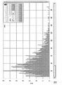
図19は、シスプラチンに暴露された細胞の生のICP−MS信号を示しており、この場合195Ptアイソトープがモニターされた。Ptのバックグラウンドレベルは実在せず、195Ptに対する共通の干渉は存在しないことから、各々のスパイクは、個々の細胞において検出されたPtを表している。1分の分析時間及び50マイクロ秒の浸透時間を利用して120万のデータポイントの全てが図19において収集された。ピークサイズの変動は、我々がこの技術において求めている情報、すなわち種々の細胞が異なる量の固有のPtを有する際の取り込み機構の洞察を反映しており、これは行われている分子機構及びPtを取り込み、保管するその能力に完全に依存している。 FIG. 19 shows the raw ICP-MS signal of cells exposed to cisplatin, in which case the 195Pt isotope was monitored. Each spike represents a Pt detected in an individual cell, as background levels of Pt are non-existent and there is no common interference with 195 Pt. All of the 1.2 million data points were collected in FIG. 19 using an analysis time of 1 minute and a penetration time of 50 microseconds. The variation in peak size reflects the information we seek in this technique, an insight into the uptake mechanism when different cells have different amounts of unique Pt, which is the molecular mechanism in which it is carried out and It depends entirely on its ability to capture and store Pt.
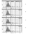
図20は、4時間にわたってシスプラチンに暴露した後のCP70におけるPt含有量の分布を示している。図21は、8時間の過程にわたるCP70卵巣癌細胞によるPtの取り込みを追跡する技術の能力を示している。図21は、細胞内のPt含有量が経時的に増加することを示しており、増加したシスプラチンの取り込みを告げており、これはこの分布において右へのシフトによって表されている。 FIG. 20 shows the distribution of Pt content in CP70 after exposure to cisplatin for 4 hours. FIG. 21 demonstrates the ability of the technique to track Pt uptake by CP70 ovarian cancer cells over an 8-hour process. FIG. 21 shows that the intracellular Pt content increases over time, signaling increased cisplatin uptake, which is represented by a shift to the right in this distribution.
平均Pt含有量と、暴露時間は、2つの連続しない日に繰り返され、単一細胞種を検出するために、本明細書に記載される噴霧チャンバを用いることの高い精度と、再現性を示している(図22)。 The average Pt content and exposure time were repeated on two non-consecutive days, demonstrating the high accuracy and reproducibility of using the spray chambers described herein to detect a single cell type. (Fig. 22).
実施例5
ナノ粒子(NP)は、種々の消費者製品の品質の改善から、癌の研究を向上させることまで広範な種々の用途において使用されている。全ての化学作用と同様に、環境へのNPの放出に関連する潜在的なリスクが存在する。感染に対する従来の対処法として、銀が主張する治癒力は現在では、臭気と闘うソックスから、微生物を回避する子供用の動物のぬいぐるみまで及ぶ多数の消費者の殺菌製品においてNP添加剤として市場に出回っている。同時に、調査研究は最終的に細胞に対するナノシルバーの毒性を示している。
Example 5
Nanoparticles (NPs) are used in a wide variety of applications, from improving the quality of various consumer products to improving cancer research. As with all chemistries, there are potential risks associated with the release of NP into the environment. As a traditional remedy for infections, silver claims healing power is now on the market as an NP additive in many consumer bactericidal products, ranging from odor-fighting socks to stuffed animals for children to avoid microbes. It is on the market. At the same time, research studies have finally shown the toxicity of nanosilver to cells.
卵巣細胞株の3つの異なる株が、2つの異なる金NP濃度に暴露された。細胞は余剰のNPを取り除くために洗浄され、その後、細胞内の含有量を判定するために21時間後に分析された。図23におけるデータは、異なる細胞株が、異なるNP取り込み率を有することを示しており、これは、ある程度までは、調査されたNP濃度に依存する可能性がある。500,000個/mLが、各バーのグループ分けの左側に示されており、1,000,000個/mLが各バーのグループ分けの右側に示されている。 Three different strains of ovarian cell lines were exposed to two different gold NP concentrations. Cells were washed to remove excess NP and then analyzed after 21 hours to determine intracellular content. The data in FIG. 23 show that different cell lines have different NP uptake rates, which may, to some extent, depend on the NP concentration investigated. 500,000 pieces / mL is shown on the left side of each bar grouping and 1,000,000 pieces / mL is shown on the right side of each bar grouping.
実施例6
本明細書に記載される噴霧チャンバはまた、いかなる事前の暴露もなしに、その自然のままの環境における細胞それ自体の固有の金属含有量を判定するのにも使用することができる。対象の金属は、細胞が懸濁した培養液の中に存在する可能性があり、バックグラウンドレベルに関与している。バックグラウンドが高い場合、それは細胞からの金属信号を不明瞭にする可能性がある。図24及び図25は、CP70卵巣癌細胞株からの個別の細胞における銅(図24)と、亜鉛(図25)の測定値を示している。
Example 6
The spray chambers described herein can also be used to determine the inherent metal content of the cells themselves in their pristine environment without any prior exposure. The metal of interest may be present in the culture medium in which the cells are suspended and is involved in the background level. If the background is high, it can obscure the metal signal from the cell. 24 and 25 show measurements of copper (FIG. 24) and zinc (FIG. 25) in individual cells from the CP70 ovarian cancer cell line.
実施例7
単一細胞ICP−MSを利用して、淡水藻によるナノ粒子及びイオン化した/溶解した金の取り込みが測定された。個々の細胞内への金属の取り込みは、金属が溶解されようと、またはナノ粒子(NP)として存在しようと、環境の研究及びヒトの健康の研究の両方にとって興味深いことである。現在は、細胞の金属含有量は、細胞をその培地から取り除き(遠心分離または濾過のいずれかによって)、新鮮な培地溶液によって洗浄し、その後ICP−MS4によって分析のためにそれらを酸蒸解することによって調べられる。この方法論は、細胞毎ではなく所与の数の細胞内の全体の金属または粒子の含有量を提供する。したがって、個々の細胞の金属濃度は、全ての細胞が、同一の量のイオン化した金属またはナノ粒子金属を蓄積するという仮定に依拠している。この仮定は、例えば透過型電子顕微鏡(TEM)、走査型電子顕微鏡(SEM)及び蛍光性追跡などの技術によって実証されるように、常に正しいわけではない。これらの顕微鏡検査技術は、細胞内へのNPの取り込みの可視化を可能にするが、これは時間を消費し、人為結果を起こしやすい。TEM及びSEMは定性であり、標識付けは、標識とNPの複合体が持続しない偽陽性を提示する可能性がある。
Example 7
Single-cell ICP-MS was used to measure the uptake of nanoparticles and ionized / dissolved gold by freshwater algae. The uptake of metals into individual cells, whether they are lysed or present as nanoparticles (NPs), is of interest to both environmental and human health studies. Currently, the metal content of cells is that the cells are removed from their medium (either by centrifugation or filtration), washed with a fresh medium solution, and then acid-evaporated for analysis by ICP-MS4. Investigate by. This methodology provides the total content of metal or particles within a given number of cells, not per cell. Therefore, the metal concentration of individual cells relies on the assumption that all cells accumulate the same amount of ionized or nanoparticle metal. This assumption is not always correct, as demonstrated by techniques such as transmission electron microscopy (TEM), scanning electron microscopy (SEM) and fluorescence tracking. These microscopic techniques allow visualization of the uptake of NP into cells, which is time consuming and prone to anthropogenic results. TEM and SEM are qualitative, and labeling can present false positives where the labeling-NP complex does not persist.
藻細胞の培養物は、200,000細胞/mLの濃度に調整され、1、2または3ppbのイオン化した金、200,000個/mL、400,000個/mLまたは600,000個/mLの金NPを含めた様々な濃度でイオン化した金または金NP(60nmNP、NIST8013)のいずれかに暴露された。各暴露の研究は、三つ組で、20℃で、74時間まで、12時間の明るい時間と、12時間の暗い時間との明るさと暗さのサイクルによって行われた。暴露中、1mLのアリコートが分析のために周期的に取り出された。分析に先だって、細胞は、暴露培地から分離され、培地によって3回洗浄された。各洗浄サイクルは、細胞を300gの力で15分間遠心分離し、1mLの新たな培地(NPまたはイオン化したAuを全く含まない)の中に再懸濁させることで構成された。3回の洗浄の後、細胞の回収は、43.8±8.6%であった。 The algae cell culture is adjusted to a concentration of 200,000 cells / mL, with 1, 2 or 3 ppb of ionized gold, 200,000 cells / mL, 400,000 cells / mL or 600,000 cells / mL. It was exposed to either gold or gold NP (60 nm NP, NIST8013) ionized at various concentrations, including gold NP. Studies of each exposure were performed in triplets at 20 ° C. up to 74 hours with a cycle of light and darkness of 12 hours of light and 12 hours of dark. During exposure, 1 mL aliquots were periodically removed for analysis. Prior to analysis, cells were separated from exposed medium and washed 3 times with medium. Each wash cycle consisted of centrifuging the cells with a force of 300 g for 15 minutes and resuspending them in 1 mL of fresh medium (without any NP or ionized Au). After 3 washes, cell recovery was 43.8 ± 8.6%.
全ての分析は、データ収集及び処理のためのSyngistix(商標)単一細胞用途のソフトウェアモジュールを利用してPerkinElmer NexION(登録商標)ICP−MS上で実施された。使用された道具的条件づけは、0.03−0.04mL/分の試料取り込み率、2.0mmの内径の石英注入器、1600ワットのRF電力、0.36L/分のネブライザーガス流量及び0.7リットル/分のメイクアップガス流であった。図2に示されるような噴霧チャンバ(但し図3、図4及び図5A〜図5Dの噴霧チャンバが代わりに使用される場合もある)を、Meinhard HENネブライザーと共に使用することができる。細胞は典型的には、プラズマへと渡されるエアロゾル液滴より大きいため、従来の噴霧チャンバは、プラズマへのその輸送を制限する。 All analyzes were performed on PerkinElmer NexION® ICP-MS utilizing a software module for Syngitix® single cell use for data collection and processing. The instrumental conditioning used was 0.03-0.04 mL / min sample uptake rate, 2.0 mm inner diameter quartz injector, 1600 watt RF power, 0.36 L / min nebulizer gas flow rate and 0. It was a make-up gas flow of .7 liters / minute. A spray chamber as shown in FIG. 2 (although the spray chambers of FIGS. 3, 4 and 5A-5D may be used instead) can be used with the Meinhard HEN nebulizer. Conventional spray chambers limit their transport to the plasma, as cells are typically larger than aerosol droplets that are passed to the plasma.
イオン化した/溶解した標準と、NP標準の両方で較正が行われた。イオン化の較正は、1、2及び3ppbの金と共に行われたのに対して、NPの較正は、10、30及び60nmの金NP(NIST8011、8012及び8013それぞれ)を使用し、50,000個/mLに調整された。細胞懸濁液を基質適合させるために、全ての標準は藻の培地の中で調整された。輸送効率は、60nmの金のNPを利用して判定された。 Calibration was performed with both ionized / dissolved standards and NP standards. Ionization calibration was performed with 1, 2 and 3 ppb gold, while NP calibration was performed with 50,000 gold NPs at 10, 30 and 60 nm (NIST 8011, 8012 and 8013 respectively). Adjusted to / mL. All standards were adjusted in algae medium to substrate match the cell suspension. Transport efficiency was determined using a 60 nm gold NP.
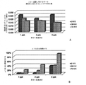
金NPの取り込みに関して細胞を分析する前に、細胞それ自体に対するAuの作用を判定する必要がある。これは、細胞を異なる濃度のイオン化した/溶解した金に、及び異なる濃度の金NPに暴露することによって達成された。その後、血球計算器を利用して細胞濃度が74時間モニターされた。図26A及び図26Bに示されるようにイオン化した金への暴露(図26A)と、NP(図26B)の金への暴露の両方に関して、暴露された細胞と、対照細胞との間で細胞濃度における有意な差は生じなかった。結果として、金は、細胞濃度に影響を及ぼすことはない。 Before analyzing cells for gold NP uptake, it is necessary to determine the effect of Au on the cells themselves. This was achieved by exposing cells to different concentrations of ionized / lysed gold and to different concentrations of gold NP. The cell concentration was then monitored for 74 hours using a hemocytometer. Cell concentrations between exposed cells and control cells for both ionized gold exposure (FIG. 26A) and NP (FIG. 26B) gold exposure as shown in FIGS. 26A and 26B. There was no significant difference in. As a result, gold does not affect cell concentration.
この研究において使用される細胞株は、クリプト藻であり、これは20〜30ミクロンのサイズの範囲を有する。ネブライザーを介しての細胞の吸引は、それらを高圧に曝す可能性があり、この高圧はネブライザー、試料の流量及びネブライザーのガス流に左右される。細胞が、噴霧中に損傷されないことを保証するために、光学顕微鏡検査を利用して噴霧プロセスの前後に細胞を集計することによって様々な試料の取り込み及びネブライザーのガス流が評価された。図27は、100%の細胞が、ネブライザーのガス流が0.5mL/分までの状態で100マイクロリットル/分の試料の流量において無傷であることを示している。したがって、選択された道具的条件づけの下で、全ての細胞が完全に無傷の状態で噴霧チャンバに進入するはずである。 The cell line used in this study is Cryptophyceae, which has a size range of 20-30 microns. Aspiration of cells through the nebulizer can expose them to high pressure, which depends on the nebulizer, sample flow rate and nebulizer gas flow. Various sample uptakes and nebulizer gas flow were evaluated by aggregating the cells before and after the spraying process using light microscopy to ensure that the cells were not damaged during spraying. FIG. 27 shows that 100% of the cells are intact at a sample flow rate of 100 microliters / min with the nebulizer gas flow up to 0.5 mL / min. Therefore, under selected instrumental conditioning, all cells should enter the spray chamber in a completely intact condition.
洗浄後の細胞から測定された信号は、細胞それ自体の中にある金属に起因しており、最初の暴露から残った残余の金属からではないことを確証することが重要である。よって、NPが、洗浄サイクル後は細胞培地の中に存続しないことを確信することが重要である。このことをチェックするために、細胞は新鮮な培地によって3回洗浄された。培地の中のNP含有量をモニターするために、各細胞の洗浄サイクルの浮遊物がSC−ICP−MSによって分析された。NP含有量は、3回の洗浄サイクルにわたって減少することが見い出され、3回目の洗浄の後は、粒子は全く検出されなかった。 It is important to ensure that the signal measured from the washed cells is due to the metal within the cells themselves, not from the residual metal remaining from the initial exposure. Therefore, it is important to be confident that the NP will not survive in the cell culture medium after the wash cycle. To check this, cells were washed 3 times with fresh medium. In order to monitor the NP content in the medium, the suspension of the wash cycle of each cell was analyzed by SC-ICP-MS. The NP content was found to decrease over 3 wash cycles and no particles were detected after the 3rd wash.
SC−ICP−MSの主な利点の1つは、NPを含む細胞の正確な数ではなく、単一のまたは多数のNPを含むそのような細胞の割合を判定することが可能であることである。図28A〜図28Dにおいて、細胞内の単一のNP(1NP/1C≡1粒子/1細胞と標識される)に起因する1700ag前後のメインのピークが存在している。細胞から収集された信号は、2つ以上の粒子を含む細胞の増加と同調する、74時間にわたる金の金属を含む細胞の増加を示している。2時間の暴露時間(図28A)、28時間の暴露時間(図28B)、53時間の暴露時間(図28C)及び74時間の暴露時間(図28D)である。1NP/1C=細胞当たり1NP、2NP/1C=細胞当たり2NP、3NP/1C=細胞当たり3NPである。単一の60nmのAuNPは≒1800ag(これより先で考察したように)であるため、このとき1つの細胞から測定されたおよそ1700agの金の質量は、この細胞内の単一の60nmの金NPに相当する。この質量のわずかな減少は、細胞内にあるNPから生じると考えられており、これは、将来の研究において顕微鏡検査法によって探求されるであろう。暴露時間は2時間(図28A)から74時間(図28D)まで増大する際、細胞当たりの多数の細胞の存在を、A〜Cにおいて2NP/1C及び3NP/1Cとそれぞれ印が付けられた3400ag(2NP)及び5200ag(3NP)に現れるピークとして見ることができる。細胞当たりのNPの数を判定する能力によって、様々な数のNPを含む細胞の割合を経時的に、かつ藻培地におけるNP濃度に応じて追跡することができる。暴露時間が増加するにつれて、我々が予測したように1NPを有する細胞の数が増加する。また培地におけるNPの濃度が200,000から600,000個/mLまで増大するにつれて、より高い割合の細胞が単一のNPを含ようになる。600,000個/mLの暴露において2NP及び3NPを含む細胞の数にも同様の傾向が見られる。しかしながら200,000個/mLの場合、2つ以上のナノ粒子を取り込む細胞の数は、取り込み率に対する暴露時間の作用に関して何らかの結論を引き出すにはあまりに小さい。 One of the main advantages of SC-ICP-MS is that it is possible to determine the proportion of such cells containing a single or multiple NPs rather than the exact number of cells containing NPs. is there. In FIGS. 28A-28D, there is a main peak around 1700ag due to a single intracellular NP (labeled 1NP / 1C≡1 particle / cell). The signals collected from the cells show an increase in cells containing gold metal over 74 hours, synchronized with an increase in cells containing two or more particles. 2 hours exposure time (FIG. 28A), 28 hours exposure time (FIG. 28B), 53 hours exposure time (FIG. 28C) and 74 hours exposure time (FIG. 28D). 1NP / 1C = 1NP per cell, 2NP / 1C = 2NP per cell, 3NP / 1C = 3NP per cell. Since a single 60 nm AuNP is approximately 1800 ag (as discussed earlier), the mass of approximately 1700 ag of gold measured from one cell at this time is a single 60 nm gold within this cell. Corresponds to NP. This slight reduction in mass is believed to result from the NP inside the cell, which will be explored by microscopic examination in future studies. When the exposure time increased from 2 hours (FIG. 28A) to 74 hours (FIG. 28D), the presence of a large number of cells per cell was marked 3400ag in A-C as 2NP / 1C and 3NP / 1C, respectively. It can be seen as a peak appearing at (2NP) and 5200ag (3NP). The ability to determine the number of NPs per cell allows the proportion of cells containing varying numbers of NPs to be tracked over time and according to the concentration of NPs in the algae medium. As the exposure time increases, the number of cells with 1 NP increases, as we predicted. Also, as the concentration of NPs in the medium increases from 200,000 to 600,000 cells / mL, a higher percentage of cells will contain a single NP. A similar trend is seen in the number of cells containing 2NP and 3NP at 600,000 cells / mL exposure. However, at 200,000 cells / mL, the number of cells that uptake two or more nanoparticles is too small to draw any conclusions regarding the effect of exposure time on uptake rates.
イオン化した金の細胞の取り込み率を判定するために、藻細胞が、1、2及び3マイクログラム/Lの溶解した金の濃度に74時間までにわたって暴露され、2、28及び74時間で試料アリコートが取り出された。図29Aに示されるように、経時的な細胞当たりの金の平均的な量の明白な低下が生じており、これは最初の金濃度に依存している。図29Aの各々のバーのグループ分けにおいて左から右に、順序は2時間、28時間及び74時間である。しかしながら図29Bに実証されるように、金を含む細胞の割合は、経時的に、かつ最初のAu暴露濃度と共に増大する。図29Bの各々のバーのグループ分けにおいて左から右に、順序は2時間、28時間及び74時間である。これらのデータは、細胞内に取り込まれる金の量を制限する細胞の機構が存在しており、これは細胞培地における金の濃度に依存していることを示唆している。 To determine the uptake rate of ionized gold cells, algae cells were exposed to concentrations of 1, 2 and 3 micrograms / L of lysed gold for up to 74 hours and sample aliquots at 2, 28 and 74 hours. Was taken out. As shown in FIG. 29A, there is a clear decrease in the average amount of gold per cell over time, which depends on the initial gold concentration. From left to right in the grouping of each bar in FIG. 29A, the order is 2 hours, 28 hours and 74 hours. However, as demonstrated in FIG. 29B, the proportion of gold-containing cells increases over time and with initial Au exposure concentration. From left to right in the grouping of each bar in FIG. 29B, the order is 2 hours, 28 hours and 74 hours. These data suggest that there is a cellular mechanism that limits the amount of gold taken up into the cell, which depends on the concentration of gold in the cell culture.
実施例8
シスプラチン、カルボプラチン及びオキサリプラチンは、西欧諸国で最も広く使用される白金を用いた癌の化学療法薬剤である。シスプラチンの有効性は、DNAに結合するその能力に起因しており、結果としてDNA−白金(Pt) 付加物が生じ、これがDNAを歪める。細胞は、このときDNAの損傷を修復する必要があり、そうでなければDNAの複製は阻止され、結果として細胞死が生じる。
Example 8
Cisplatin, carboplatin and oxaliplatin are the most widely used platinum-based chemotherapeutic agents in Western Europe. The effectiveness of cisplatin is due to its ability to bind to DNA, resulting in a DNA-platinum (Pt) adduct, which distorts the DNA. The cell then needs to repair the DNA damage, otherwise DNA replication is blocked, resulting in cell death.
多くの癌は、最初は、白金を用いた処置に対して敏感に反応するが、腫瘍が頻繁にぶり返す患者は、さらなるシスプラチン療法に対する耐性を見せる。シスプラチン薬剤耐性は、3つの主要な分子機構に起因するものであり、すなわち増大したDNA修復、増大したサイトソル不活性化、及び改変した細胞の蓄積である。細胞のシスプラチン取り込み量の減少、及び細胞のシスプラチン排出の増大が、改変した細胞の蓄積に伴う機構を構成している。 Many cancers initially respond sensitively to platinum-based treatment, but patients with frequent tumor relapses develop resistance to additional cisplatin therapy. Cisplatin drug resistance is due to three major molecular mechanisms: increased DNA repair, increased cytosol inactivation, and altered cell accumulation. Decreased cellular cisplatin uptake and increased cellular cisplatin excretion constitute the mechanism associated with the accumulation of modified cells.
2つの卵巣癌細胞株におけるシスプラチン取り込みが、単一粒子ICP−MS(SP−ICP−MS)を利用して評価された。卵巣癌細胞株A2780及びA2780/CP70が全ての実験で使用された。細胞は、5%のCO2の下に、37℃で、10%の牛血清(FBS、Gibco(商標))、インシュリン(Sigma−Aldrich(商標))、L−グルタミン酸(Gibco(商標)及びペン/連鎖球菌(Gibco(商標))が補充されたRPMI1641培地(Gibco(商標))において成長させられた。血清飢餓実験のために、細胞は、平板培養され、皿に付着するようにされた。培地は取り除かれ、おおよそ18時間の間、血清を含まない培地と交換され、その後、培地は、シスプラチン処理を開始するために通常の培地と交換された。シスプラチンは、1mg/mLで無菌食塩水中で再懸濁され、処置に先だって30分間勢いよく揺さぶられた。試料が、処理後の1時間、2時間、4時間及び8時間のところで収集される時間的経過にわたって、細胞は30μmのシスプラチンによって処理された。分析のために、細胞はリン酸塩緩衝食塩水(PBS)によって2回洗浄され、非酵素細胞分離溶液Cellstripper(Corning(商標))を用いて収集された。細胞は、500xgで10分間遠心分離機にかけられた。浮遊物が廃棄され、細胞は、1mLのPBS中に再懸濁され、70μmナイロンメッシュを介して濾過され、血球計算器の集計によって数が定量された。細胞は、100,000細胞/mLの最終濃度までPBS中で希釈され、注入まで氷の上で保持された。
Cisplatin uptake in two ovarian cancer cell lines was evaluated using single particle ICP-MS (SP-ICP-MS). Ovarian cancer cell lines A2780 and A2780 / CP70 were used in all experiments. Cells are under 5% CO2 at 37 ° C., 10% fetal bovine serum (FBS, Gibco ™), insulin (Sigma-Aldrich ™), L-glutamic acid (Gibco ™) and pen / The cells were grown in RPMI1641 medium (Gibco ™) supplemented with Streptococcus (Gibco ™). For serum starvation experiments, the cells were plate-cultured and allowed to adhere to the dish. Was removed and replaced with serum-free medium for approximately 18 hours, after which the medium was replaced with normal medium to initiate the cisplatin treatment. Sisplatin at 1 mg / mL in sterile saline. The cells were resuspended and shaken vigorously for 30 minutes prior to treatment. Cells were treated with 30 μm cisplatin over the time course in which the samples were collected 1 hour, 2 hours, 4 hours and 8 hours after treatment. For analysis, cells were washed twice with phosphate buffered saline (PBS) and collected using a non-enzymatic cell isolation solution Celltripper (Corning ™). Cells were collected at 500
分析は、データ収集及び処理のためのSyngistix(商標)単一細胞用途のソフトウェアモジュールを利用して、PerkinElmerのNexION(登録商標)ICP−MSによって実施された。道具的条件づけは、以下の通り、試料取り込み率0.04mL/分、2.0mmの内径の石英注入器、1600ワットRF電力、0.36L/分のネブライザーガスの流量、0.7L/分のメイクアップガスの流量、及び60秒の試料分析時間であった。Meinhard HENネブライザー及び図2の噴霧チャンバも使用された(但し、図3、図4及び図5A〜図5Dの噴霧チャンバが代わりに使用される場合もある)。単一細胞試料投入キット(部品番号N8150031)が、NexIONへの試料の投入に使用された。このキットは、高い効率のネブライザー(部品番号N8142046)と、細胞をプラズマに輸送するように設計された噴霧チャンバとで構成されている。細胞(1〜100ミクロン)は、従来の噴霧チャンバを典型的に通過する液滴(2ミクロン未満)より大きい。 The analysis was performed by PerkinElmer's NexION® ICP-MS utilizing a Syngitix® single cell application software module for data collection and processing. The instrumental conditioning is as follows: sample uptake rate 0.04 mL / min, 2.0 mm inner diameter quartz injector, 1600 watt RF power, 0.36 L / min nebulizer gas flow rate, 0.7 L / min. The flow rate of make-up gas and the sample analysis time of 60 seconds. A Meinhard HEN nebulizer and the spray chamber of FIG. 2 were also used (although the spray chambers of FIGS. 3, 4 and 5A-5D may be used instead). A single cell sample loading kit (part number N8150031) was used to feed the sample into Nexion. The kit consists of a highly efficient nebulizer (part number N81402446) and a spray chamber designed to transport cells to the plasma. Cells (1-100 microns) are larger than droplets (less than 2 microns) that typically pass through a conventional spray chamber.
細胞試料を基質適合させるために、イオン化された白金標準がPBS内で調整された。1、2及び3ppbの白金基準を用いて標準曲線が生成された。輸送効率が、PBS中の60ミクロンの金ナノ粒子を用いて判定された。 Ionized platinum standards were adjusted in PBS to substrate match cell samples. Standard curves were generated using platinum criteria of 1, 2 and 3 ppb. Transport efficiency was determined using 60 micron gold nanoparticles in PBS.
この研究のために選ばれた細胞は、卵巣細胞株A2780及びA2780/CP70であり、これらは、耐性に関する分子機構がシスプラチン取り込みによって改変されるため、単一細胞方法を発展させるための優れたモデルである。A2780はシスプラチンに感度が高い細胞株であり、A2780/CP70株はシスプラチンに耐性がある。このような耐性は、A2780親細胞株を増大する量のシスプラチンに暴露することによって発達させられた。A2780/CP70細胞は、DNA修復上方制御することに加えてシスプラチン取り込みを低下させることによって耐性を発達させた。我々は、シスプラチン取り込みの分布が経時的に細胞集団においてどのように変化したかを分析するために時間的経過実験を行うことによってシスプラチン取り込みを調査した。両方の細胞株が、1、2、4及び8時間にわたって30μMのシスプラチンによって処理された。試料分析中、2つのリアルタイムのグラフが形成され、1つは、強度反応と試料の数を示し、2番目は、このデータを取り込み、それを反応の頻度と、細胞当たりの質量を示すヒストグラムに変換し、これらの両方のグラフは、図30A及び図30Bに示されており、図30A(数と測定値)はリアルタイム信号を表しており(数と測定値)、図30B(頻度とピークエリア(数))は、リアルタイムのヒストグラムを表している(頻度とピークエリア(数))。データが収集された後、図30C(周波数と質量(ag))に示されるように、質量分布のピークを統合することができる。 The cells selected for this study were the ovarian cell lines A2780 and A2780 / CP70, which are excellent models for developing single-cell methods because the molecular mechanism for resistance is altered by cisplatin uptake. Is. A2780 is a cell line highly sensitive to cisplatin, and A2780 / CP70 strain is resistant to cisplatin. Such resistance was developed by exposing the A2780 parental cell line to an increasing amount of cisplatin. A2780 / CP70 cells developed resistance by reducing cisplatin uptake in addition to upregulating DNA repair. We investigated cisplatin uptake by performing temporal follow-up experiments to analyze how the distribution of cisplatin uptake changed in the cell population over time. Both cell lines were treated with 30 μM cisplatin for 1, 2, 4 and 8 hours. During sample analysis, two real-time graphs were formed, one showing the intensity response and the number of samples, and the second taking this data into a histogram showing the frequency of the reaction and the mass per cell. Transformed, both of these graphs are shown in FIGS. 30A and 30B, where FIG. 30A (numbers and measurements) represents a real-time signal (numbers and measurements) and FIG. 30B (frequency and peak area). (Number)) represents a real-time histogram (frequency and peak area (number)). After the data is collected, the peaks of the mass distribution can be integrated as shown in FIG. 30C (Frequency and Mass (ag)).
シスプラチンの時間的経過の結果が、図31Aから図31D及び図32A〜図32Dに示される。図31Aは、1時間の露光におけるA2780細胞を表しており、図31Bは、2時間の露光におけるA2780細胞を表しており、図31Cは、4時間の露光におけるA2780細胞を表しており、図31Dは、4時間の露光におけるA2780細胞を表している。図32Aは、1時間の露光におけるA2780/CP70細胞を表しており、図32Bは、2時間の露光におけるA2780/CP70細胞を表しており、図32Cは、4時間の露光におけるA2780/CP70細胞を表しており、図32Dは、4時間の露光におけるA2780/CP70細胞を表している。各グラフに関するy軸は、頻度を表しており、x軸は質量(ag)を表している。 The results of the temporal course of cisplatin are shown in FIGS. 31A-31D and 32A-32D. FIG. 31A represents A2780 cells at 1 hour exposure, FIG. 31B represents A2780 cells at 2 hours exposure, FIG. 31C represents A2780 cells at 4 hours exposure, and FIG. 31D. Represents A2780 cells at 4 hours exposure. FIG. 32A represents A2780 / CP70 cells at 1 hour exposure, FIG. 32B represents A2780 / CP70 cells at 2 hours exposure, and FIG. 32C represents A2780 / CP70 cells at 4 hours exposure. Represented, FIG. 32D represents A2780 / CP70 cells at 4 hour exposure. The y-axis for each graph represents frequency and the x-axis represents mass (ag).
1時間のシスプラチンの処置において、両方の細胞株は、白金の取り込みをほとんど示さない。時間が進むと、両方の株からの細胞は、増大する量のシスプラチンを取り込み、不均一な分布を示す。シスプラチン処理の8時間後、A2780及びA2780/CP70細胞株は、細胞集団の残りのものと比べて、より少ないシスプラチンを含む細胞のサブ集団を有する。加えて、A2780は、A2780/CP70よりも多くのシスプラチンを含む増大した母集団を有するため、8時間における細胞株の間には有意な差が生じている。 At 1 hour of treatment with cisplatin, both cell lines show little platinum uptake. Over time, cells from both strains take up increasing amounts of cisplatin and show a heterogeneous distribution. Eight hours after cisplatin treatment, the A2780 and A2780 / CP70 cell lines have a subpopulation of cells containing less cisplatin than the rest of the cell population. In addition, A2780 has an increased population containing more cisplatin than A2780 / CP70, resulting in significant differences between cell lines at 8 hours.
時間的経過データは、各々のヒストグラムを対数正規曲線に適合させることによって要約された。図33に示されるように、経時的なA2780細胞と、A2780/CP70細胞のシスプラチン取り込みの違いを示すために、各時間点に関する平均強度が判定され、グラフにされた。シスプラチンに感度が高いA2780細胞は、経時的にシスプラチンに耐性のあるA2780/CP70と比較して増大したシスプラチンの取り込みを有することが観察された。 The time course data was summarized by fitting each histogram to a lognormal curve. As shown in FIG. 33, the average intensity for each time point was determined and graphed to show the difference in cisplatin uptake between A2780 cells and A2780 / CP70 cells over time. It was observed that A2780 cells, which are sensitive to cisplatin, have increased cisplatin uptake compared to A2780 / CP70, which is resistant to cisplatin over time.
シスプラチン取り込みの不均一な分布が、細胞周期における違いによるものかどうかを判定するために、細胞は、血清飢餓状態に置かれた。細胞が組織培養物の中で成長させられる際、培養物は典型的には、異なる速度で成長する非同期細胞の混合物であり、結果として、細胞周期の異なる段階において様々な細胞が生じることになる。細胞周期の4つの部分は、G1、S、G2及びMと呼ばれる。G1段階は、最初の(及び典型的には最も長い)成長段階であり、その後にS段階が続き、そこでは細胞分裂のための準備においてDNAが合成され、複製される。G2成長段階が次であり、その後にM(または有糸分裂)段階が続き、そこで細胞が2つの細胞に分裂する。よってシスプラチンレベルにおける差は、細胞周期の段階が異なるためであり得ることがもっともらしく思われる。血清の細胞を飢餓状態にすることによって、成長因子が培地から取り除かれ、細胞は、G1段階に留まることになる。 Cells were placed in serum starvation to determine if the heterogeneous distribution of cisplatin uptake was due to differences in the cell cycle. When cells are grown in a tissue culture, the culture is typically a mixture of asynchronous cells that grow at different rates, resulting in different cells at different stages of the cell cycle. .. The four parts of the cell cycle are called G1, S, G2 and M. The G1 stage is the first (and typically the longest) growth stage, followed by the S stage, where DNA is synthesized and replicated in preparation for cell division. The G2 growth stage is next, followed by the M (or mitotic) stage, where the cell divides into two cells. Therefore, it seems plausible that the difference in cisplatin levels may be due to different stages of the cell cycle. By starving the serum cells, the growth factors are removed from the medium and the cells remain in the G1 stage.
シスプラチンの取り込み時間の実験が繰り返され、血清飢餓状態に置かれた細胞と、対照細胞との取り込みの差を比較した。図34A及び図34Bは、血清飢餓実験の結果を示しており、そこでは平均強度が、各時間点に関して判定され、グラフにされた。これらの結果は、血清飢餓は、A2780細胞株またはA2780/CP70細胞株のいずれにおいてもシスプラチンの取り込みに対して全く影響を持たないことを示しており、これらは共に、対照細胞と同様のシスプラチン取り込み率を示している。よってこのような結果は、細胞におけるシスプラチンの取り込みの不均一な分布は、細胞周期によるものであることを示唆しており、もっと正確に言えば何らかの他の知られていない機構によるものであるということを示唆している。 Experiments on cisplatin uptake time were repeated to compare the difference in uptake between serum-starved cells and control cells. 34A and 34B show the results of the serum starvation experiment, where the average intensity was determined and graphed for each time point. These results indicate that serum starvation has no effect on cisplatin uptake in either the A2780 cell line or the A2780 / CP70 cell line, both of which are similar to control cells in cisplatin uptake. Shows the rate. Thus, these results suggest that the heterogeneous distribution of cisplatin uptake in cells is due to the cell cycle, or more precisely to some other unknown mechanism. It suggests that.
実施例9
流れシミュレーションが、コンピュータによる流体力学シミュレーションを利用して、図5A〜図5Dに示される噴霧チャンバを用いて行われた。図35は、シミュレーションの結果を示している。図35は、前方方向(ネブライザーの先端から離れる方向)におけるガス流の軸方向の速度を示している。液滴は、接線方向の流れの中に限定され、外側チャンバの内側面からは離れたままである。
Example 9
Flow simulations were performed using the spray chambers shown in FIGS. 5A-5D, utilizing computerized hydrodynamic simulations. FIG. 35 shows the result of the simulation. FIG. 35 shows the axial velocity of the gas flow in the forward direction (the direction away from the tip of the nebulizer). The droplets are confined to the tangential flow and remain away from the inner surface of the outer chamber.
本明細書に開示される実施例の要素を紹介する際、冠詞「1つの(a)」、「1つの(an)」、「その(the)」及び「前記(said)」は、その要素のうちの1つまたは複数が存在することを意味することが意図されている。用語「備える(comprising)」、「含む(「including)」及び「有する(having)」は、オープンエンドであり、列挙された要素以外の追加の要素も存在し得ることが意図されている。本開示の利益が与えられた仮定すると、実施例の種々の構成要素は、相互に入れ替えることが可能である、または他の事例における種々の構成要素で代用することもできることは当業者によって理解されるであろう。 In introducing the elements of the examples disclosed herein, the articles "one (a)", "one (an)", "the" and "said" are the elements. It is intended to mean that one or more of them are present. The terms "comprising", "inclusion" and "having" are open-ended and it is intended that additional elements other than those listed may also exist. It will be appreciated by those skilled in the art that, given the benefits of the present disclosure, the various components of the examples can be interchanged with each other or can be replaced by various components in other cases. Will be.
特定の態様、実施例及び実施形態を上記に記載してきたが、本開示の利益が与えられた仮定すると、開示される例示の態様、実施例及び実施形態の追加、代用、修正及び改変が可能であることは当業者によって理解されるであろう。 Although specific embodiments, examples and embodiments have been described above, it is possible to add, substitute, modify and modify the disclosed exemplary embodiments, examples and embodiments given the benefits of the present disclosure. Will be understood by those skilled in the art.
Claims (14)
前記外側チャンバ内の内側の管をさらに備え、前記内側の管は、複数のマイクロチャネルを備え、前記複数のマイクロチャネルの各々は、前記内側の管での液滴の沈着を抑えるために前記外側チャンバのメイクアップガス入口からメイクアップガスを受容するようにサイズが決められ配置されている、噴霧チャンバ。 An outer chamber, the outer chamber, the each configured to receive a gas to provide a gas flow in the outer chamber, an inlet end, an outlet end, and a drainage pipe, the two With a make-up gas inlet, the inlet end is configured to bind to the nebulizer to receive a liquid sample from the nebulizer, and the outlet end is configured to spray an aerosolized sample.
Further comprising an inner tube within the outer chamber, the inner tube is provided with a plurality of micro-channels, each of the previous SL plurality of microchannels, wherein in order to suppress the deposition of droplets in the inner tube A spray chamber that is sized and arranged to receive make-up gas from the make-up gas inlet of the outer chamber.
Applications Claiming Priority (3)
| Application Number | Priority Date | Filing Date | Title |
|---|---|---|---|
| US201662337997P | 2016-05-18 | 2016-05-18 | |
| US62/337,997 | 2016-05-18 | ||
| PCT/US2017/033063 WO2017201143A1 (en) | 2016-05-18 | 2017-05-17 | Spray chambers and methods of using them |
Publications (3)
| Publication Number | Publication Date |
|---|---|
| JP2019521366A JP2019521366A (en) | 2019-07-25 |
| JP2019521366A5 JP2019521366A5 (en) | 2020-06-25 |
| JP6889772B2 true JP6889772B2 (en) | 2021-06-18 |
Family
ID=60326194
Family Applications (1)
| Application Number | Title | Priority Date | Filing Date |
|---|---|---|---|
| JP2019512942A Active JP6889772B2 (en) | 2016-05-18 | 2017-05-17 | Spray chambers and how to use them |
Country Status (8)
| Country | Link |
|---|---|
| US (4) | US10147592B2 (en) |
| EP (1) | EP3459323A4 (en) |
| JP (1) | JP6889772B2 (en) |
| KR (1) | KR102042436B1 (en) |
| CN (1) | CN109964541B (en) |
| AU (1) | AU2017268310B8 (en) |
| CA (1) | CA3024740A1 (en) |
| WO (1) | WO2017201143A1 (en) |
Families Citing this family (10)
| Publication number | Priority date | Publication date | Assignee | Title |
|---|---|---|---|---|
| US10804091B2 (en) * | 2016-05-18 | 2020-10-13 | Perkinelmer Health Sciences Canada, Inc. | Single particle analysis using optical detection |
| US11648574B2 (en) * | 2017-05-12 | 2023-05-16 | Sumco Corporation | Spray chamber, sample atomization and introduction device, analysis device, and method of analyzing component in sample |
| US11630039B1 (en) * | 2018-08-07 | 2023-04-18 | Elemental Scientific, Inc. | Spray chamber having dual input ports for impingement gas and sensitivity enhancement gas addition |
| US11075066B2 (en) * | 2018-10-26 | 2021-07-27 | Agilent Technologies, Inc. | Automated detection of nanoparticles using single-particle inductively coupled plasma mass spectrometry (SP-ICP-MS) |
| WO2020150126A1 (en) * | 2019-01-14 | 2020-07-23 | Agilent Technologies, Inc. | Versatile tube-free jet for gc detector |
| EP3921086A4 (en) * | 2019-02-04 | 2022-11-02 | Glass Expansion Pty. Limited | Analytic nebuliser |
| EP3949694A4 (en) * | 2019-04-01 | 2022-12-28 | Perkinelmer Health Sciences Canada, Inc | Devices and methods to improve background equivalent concentrations of elemental species |
| KR102137911B1 (en) * | 2019-09-16 | 2020-07-27 | 강원대학교산학협력단 | Method for producing transgenic spermatogonial stem cells |
| KR102571890B1 (en) * | 2021-11-29 | 2023-08-30 | 한국생산기술연구원 | Metal nanoparticles collection device for Surface Enhanced Raman Scattering |
| AU2023202154A1 (en) | 2022-04-08 | 2023-10-26 | Glass Expansion Pty. Limited | A flow control device |
Family Cites Families (23)
| Publication number | Priority date | Publication date | Assignee | Title |
|---|---|---|---|---|
| US4990740A (en) * | 1989-03-06 | 1991-02-05 | The Dow Chemical Company | Intra-microspray ICP torch |
| US5012065A (en) * | 1989-11-20 | 1991-04-30 | New Mexico State University Technology Transfer Corporation | Inductively coupled plasma torch with laminar flow cooling |
| US4958529A (en) * | 1989-11-22 | 1990-09-25 | Vestec Corporation | Interface for coupling liquid chromatography to solid or gas phase detectors |
| JP2633974B2 (en) * | 1990-04-18 | 1997-07-23 | 株式会社日立製作所 | Equipment for sample ionization and mass spectrometry |
| EP0560537A1 (en) * | 1992-03-10 | 1993-09-15 | Mds Health Group Limited | Apparatus and method for liquid sample introduction |
| JP2852838B2 (en) | 1992-09-10 | 1999-02-03 | セイコーインスツルメンツ株式会社 | Inductively coupled plasma mass spectrometer |
| US5868322A (en) * | 1996-01-31 | 1999-02-09 | Hewlett-Packard Company | Apparatus for forming liquid droplets having a mechanically fixed inner microtube |
| US5969352A (en) * | 1997-01-03 | 1999-10-19 | Mds Inc. | Spray chamber with dryer |
| JP3831415B2 (en) * | 1997-01-03 | 2006-10-11 | エムディーエス インコーポレーテッド | Spray chamber with dryer |
| JPH11326165A (en) * | 1998-05-18 | 1999-11-26 | Yokogawa Analytical Systems Inc | Atomization introduction device of sample liquid |
| JP3836693B2 (en) * | 2001-07-30 | 2006-10-25 | 独立行政法人科学技術振興機構 | Cross flow micro nebulizer for ICP mass spectrometry |
| JP3809099B2 (en) * | 2001-12-12 | 2006-08-16 | 株式会社堀場製作所 | Dry particle size analyzer |
| JP2006038729A (en) * | 2004-07-29 | 2006-02-09 | National Institute Of Advanced Industrial & Technology | Inductively coupled plasma torch |
| US20070023677A1 (en) * | 2005-06-29 | 2007-02-01 | Perkins Patrick D | Multimode ionization source and method for screening molecules |
| JP2008157895A (en) * | 2006-12-26 | 2008-07-10 | Horiba Ltd | Sample introducing device |
| US7595487B2 (en) * | 2007-08-24 | 2009-09-29 | Georgia Tech Research Corporation | Confining/focusing vortex flow transmission structure, mass spectrometry systems, and methods of transmitting particles, droplets, and ions |
| WO2009120642A1 (en) | 2008-03-26 | 2009-10-01 | Massachusetts Institute Of Technology | Methods for fabricating electrokinetic concentration devices |
| KR101089328B1 (en) * | 2009-12-29 | 2011-12-02 | 한국기초과학지원연구원 | Apparatus for electrospray ionization and method for electrospray ionization using the same |
| WO2011127417A2 (en) * | 2010-04-09 | 2011-10-13 | Elemental Scientific, Inc. | Torch assembly |
| WO2013061155A1 (en) * | 2011-10-26 | 2013-05-02 | Dvs Sciences Inc. | Sample transferring apparatus for mass cytometry |
| CN103762150B (en) * | 2014-01-27 | 2016-03-30 | 中国科学技术大学 | The solvent flashing auxiliary electrical of ultrasonic atomizatio sample introduction is from low-voltage optical from mass spectrometric apparatus |
| CA2937852C (en) | 2014-01-28 | 2023-03-28 | Perkinelmer Health Sciences, Inc. | Induction devices and methods of using them |
| DE102014113482B4 (en) * | 2014-09-18 | 2019-01-03 | Bruker Daltonik Gmbh | Ionization chamber with tempered gas supply |
-
2017
- 2017-05-17 JP JP2019512942A patent/JP6889772B2/en active Active
- 2017-05-17 CA CA3024740A patent/CA3024740A1/en active Pending
- 2017-05-17 US US15/597,608 patent/US10147592B2/en active Active
- 2017-05-17 EP EP17800075.8A patent/EP3459323A4/en active Pending
- 2017-05-17 KR KR1020187036673A patent/KR102042436B1/en active IP Right Grant
- 2017-05-17 CN CN201780044419.9A patent/CN109964541B/en active Active
- 2017-05-17 AU AU2017268310A patent/AU2017268310B8/en active Active
- 2017-05-17 WO PCT/US2017/033063 patent/WO2017201143A1/en unknown
-
2018
- 2018-09-28 US US16/146,752 patent/US10395912B2/en active Active
-
2019
- 2019-08-26 US US16/551,056 patent/US10796895B2/en active Active
-
2020
- 2020-09-18 US US17/025,430 patent/US11315778B2/en active Active
Also Published As
| Publication number | Publication date |
|---|---|
| JP2019521366A (en) | 2019-07-25 |
| KR20190040135A (en) | 2019-04-17 |
| US20190189416A1 (en) | 2019-06-20 |
| EP3459323A1 (en) | 2019-03-27 |
| US20170338092A1 (en) | 2017-11-23 |
| US11315778B2 (en) | 2022-04-26 |
| EP3459323A4 (en) | 2020-01-01 |
| CN109964541A (en) | 2019-07-02 |
| AU2017268310A8 (en) | 2022-12-08 |
| AU2017268310B2 (en) | 2022-12-01 |
| US10796895B2 (en) | 2020-10-06 |
| US20200161117A1 (en) | 2020-05-21 |
| AU2017268310B8 (en) | 2022-12-08 |
| US10147592B2 (en) | 2018-12-04 |
| KR102042436B1 (en) | 2019-11-08 |
| CA3024740A1 (en) | 2017-11-23 |
| CN109964541B (en) | 2021-01-01 |
| WO2017201143A1 (en) | 2017-11-23 |
| AU2017268310A1 (en) | 2019-01-03 |
| US10395912B2 (en) | 2019-08-27 |
| US20210090872A1 (en) | 2021-03-25 |
Similar Documents
| Publication | Publication Date | Title |
|---|---|---|
| JP6889772B2 (en) | Spray chambers and how to use them | |
| Pozebon et al. | Recent applications of laser ablation inductively coupled plasma mass spectrometry (LA-ICP-MS) for biological sample analysis: a follow-up review | |
| Radley et al. | A common substrate for prefrontal and hippocampal inhibition of the neuroendocrine stress response | |
| EP2216396B1 (en) | Method of capturing cell fluid and analyzing components thereof while observing cell and system for capturing and analyzing cell fluid | |
| JP2014112107A (en) | Method and device for desorption ionization by fluid injection | |
| US11609235B2 (en) | Rapid native single cell mass spectrometry | |
| CN105717250B (en) | Method for fast screening topoisomerase I inhibitor from natural product | |
| CN107314965B (en) | Sample pretreatment method based on flow type combined ICP-MS single cell protein detection | |
| Zhu et al. | Single-cell metabolite analysis by electrospray ionization mass spectrometry | |
| Liu et al. | Single-event tandem ICP-mass spectrometry for the quantification of chemotherapeutic drug-derived Pt and endogenous elements in individual human cells | |
| Krystek et al. | Analytical assessment about the simultaneous quantification of releasable pharmaceutical relevant inorganic nanoparticles in tap water and domestic waste water | |
| Hormigo et al. | Direct and indirect nigrofugal projections to the nucleus reticularis pontis caudalis mediate in the motor execution of the acoustic startle reflex | |
| Ng et al. | Gold nanoparticles induce serum amyloid A 1–Toll-like receptor 2 mediated NF-kB signaling in lung cells in vitro | |
| Du et al. | High-throughput metabolomic method based on liquid chromatography: high resolution mass spectrometry with chemometrics for metabolic biomarkers and pathway analysis to reveal the protective effects of baicalin on thyroid cancer | |
| Xu et al. | Mass spectrometry-based techniques for single-cell analysis | |
| Perry et al. | ICP-MS method for the determination of platinum in suspensions of cells exposed to cisplatin | |
| Folkard et al. | New insights into the cellular response to radiation using microbeams | |
| Guo et al. | Investigation of calcium variations in single cells and the impact of Yoda1 on osteocytes by ICP-OES | |
| New et al. | Detection and assessment of co‐association in inhalable drug particles using aerosol time‐of‐flight mass spectrometry | |
| Abduljabbar | Bio-imaging and serum analysis of zinc and other trace elements in a study of age-related diseases using inductively-coupled plasma mass spectrometry | |
| Tanuma et al. | Imaging of cisplatin in single cancer cell and visualizing its mechanism of action by FIB-TOF-SIMS | |
| de Carvalho | Multimodal surface microscopy applied to healthcare technologies | |
| Brodsky et al. | La cellule et ses éléments | |
| TW201633365A (en) | Focusing ionization device and mass spectrometer | |
| Kardjaputri | Dose response relationship between the chemical composition of 2.4 micrometer particles and human lung cells (A549) cytokine expression |
Legal Events
| Date | Code | Title | Description |
|---|---|---|---|
| A521 | Request for written amendment filed |
Free format text: JAPANESE INTERMEDIATE CODE: A523 Effective date: 20190206 |
|
| A521 | Request for written amendment filed |
Free format text: JAPANESE INTERMEDIATE CODE: A523 Effective date: 20200518 |
|
| A621 | Written request for application examination |
Free format text: JAPANESE INTERMEDIATE CODE: A621 Effective date: 20200518 |
|
| A871 | Explanation of circumstances concerning accelerated examination |
Free format text: JAPANESE INTERMEDIATE CODE: A871 Effective date: 20200601 |
|
| A975 | Report on accelerated examination |
Free format text: JAPANESE INTERMEDIATE CODE: A971005 Effective date: 20200707 |
|
| A131 | Notification of reasons for refusal |
Free format text: JAPANESE INTERMEDIATE CODE: A131 Effective date: 20200714 |
|
| A601 | Written request for extension of time |
Free format text: JAPANESE INTERMEDIATE CODE: A601 Effective date: 20201013 |
|
| A601 | Written request for extension of time |
Free format text: JAPANESE INTERMEDIATE CODE: A601 Effective date: 20201211 |
|
| A521 | Request for written amendment filed |
Free format text: JAPANESE INTERMEDIATE CODE: A523 Effective date: 20210113 |
|
| TRDD | Decision of grant or rejection written | ||
| A01 | Written decision to grant a patent or to grant a registration (utility model) |
Free format text: JAPANESE INTERMEDIATE CODE: A01 Effective date: 20210323 |
|
| A601 | Written request for extension of time |
Free format text: JAPANESE INTERMEDIATE CODE: A601 Effective date: 20210420 |
|
| A61 | First payment of annual fees (during grant procedure) |
Free format text: JAPANESE INTERMEDIATE CODE: A61 Effective date: 20210521 |
|
| R150 | Certificate of patent or registration of utility model |
Ref document number: 6889772 Country of ref document: JP Free format text: JAPANESE INTERMEDIATE CODE: R150 |
|
| S111 | Request for change of ownership or part of ownership |
Free format text: JAPANESE INTERMEDIATE CODE: R313113 |
|
| R350 | Written notification of registration of transfer |
Free format text: JAPANESE INTERMEDIATE CODE: R350 |