JP6888918B2 - Solid oxide fuel cell test equipment - Google Patents
Solid oxide fuel cell test equipment Download PDFInfo
- Publication number
- JP6888918B2 JP6888918B2 JP2016072187A JP2016072187A JP6888918B2 JP 6888918 B2 JP6888918 B2 JP 6888918B2 JP 2016072187 A JP2016072187 A JP 2016072187A JP 2016072187 A JP2016072187 A JP 2016072187A JP 6888918 B2 JP6888918 B2 JP 6888918B2
- Authority
- JP
- Japan
- Prior art keywords
- anode
- cathode
- fuel
- battery unit
- diversion plate
- Prior art date
- Legal status (The legal status is an assumption and is not a legal conclusion. Google has not performed a legal analysis and makes no representation as to the accuracy of the status listed.)
- Active
Links
- 239000000446 fuel Substances 0.000 title claims description 84
- 238000012360 testing method Methods 0.000 title claims description 25
- 239000007787 solid Substances 0.000 title claims description 23
- XLYOFNOQVPJJNP-UHFFFAOYSA-N water Substances O XLYOFNOQVPJJNP-UHFFFAOYSA-N 0.000 claims description 36
- 239000007789 gas Substances 0.000 claims description 34
- 239000000945 filler Substances 0.000 claims description 10
- 238000010438 heat treatment Methods 0.000 claims description 6
- 239000002184 metal Substances 0.000 claims description 2
- 239000002737 fuel gas Substances 0.000 claims 1
- UFHFLCQGNIYNRP-UHFFFAOYSA-N Hydrogen Chemical compound [H][H] UFHFLCQGNIYNRP-UHFFFAOYSA-N 0.000 description 16
- 239000001257 hydrogen Substances 0.000 description 15
- 229910052739 hydrogen Inorganic materials 0.000 description 15
- 238000007689 inspection Methods 0.000 description 9
- 230000000694 effects Effects 0.000 description 7
- 230000002411 adverse Effects 0.000 description 6
- 238000004519 manufacturing process Methods 0.000 description 5
- 238000005868 electrolysis reaction Methods 0.000 description 4
- 238000006243 chemical reaction Methods 0.000 description 3
- 238000001514 detection method Methods 0.000 description 3
- 238000005259 measurement Methods 0.000 description 3
- 230000002093 peripheral effect Effects 0.000 description 3
- 238000009792 diffusion process Methods 0.000 description 2
- 230000005611 electricity Effects 0.000 description 2
- 238000010248 power generation Methods 0.000 description 2
- 230000004308 accommodation Effects 0.000 description 1
- PNEYBMLMFCGWSK-UHFFFAOYSA-N aluminium oxide Inorganic materials [O-2].[O-2].[O-2].[Al+3].[Al+3] PNEYBMLMFCGWSK-UHFFFAOYSA-N 0.000 description 1
- 239000006227 byproduct Substances 0.000 description 1
- 239000000919 ceramic Substances 0.000 description 1
- 238000007796 conventional method Methods 0.000 description 1
- 230000006866 deterioration Effects 0.000 description 1
- 239000003792 electrolyte Substances 0.000 description 1
- 230000008020 evaporation Effects 0.000 description 1
- 238000001704 evaporation Methods 0.000 description 1
- 230000007774 longterm Effects 0.000 description 1
- 239000000463 material Substances 0.000 description 1
- 229910021645 metal ion Inorganic materials 0.000 description 1
- 239000007769 metal material Substances 0.000 description 1
- 231100000572 poisoning Toxicity 0.000 description 1
- 230000000607 poisoning effect Effects 0.000 description 1
- 230000010287 polarization Effects 0.000 description 1
- 230000003252 repetitive effect Effects 0.000 description 1
- 239000008400 supply water Substances 0.000 description 1
- 230000001960 triggered effect Effects 0.000 description 1
Images


Classifications
-
- Y—GENERAL TAGGING OF NEW TECHNOLOGICAL DEVELOPMENTS; GENERAL TAGGING OF CROSS-SECTIONAL TECHNOLOGIES SPANNING OVER SEVERAL SECTIONS OF THE IPC; TECHNICAL SUBJECTS COVERED BY FORMER USPC CROSS-REFERENCE ART COLLECTIONS [XRACs] AND DIGESTS
- Y02—TECHNOLOGIES OR APPLICATIONS FOR MITIGATION OR ADAPTATION AGAINST CLIMATE CHANGE
- Y02E—REDUCTION OF GREENHOUSE GAS [GHG] EMISSIONS, RELATED TO ENERGY GENERATION, TRANSMISSION OR DISTRIBUTION
- Y02E60/00—Enabling technologies; Technologies with a potential or indirect contribution to GHG emissions mitigation
- Y02E60/30—Hydrogen technology
- Y02E60/36—Hydrogen production from non-carbon containing sources, e.g. by water electrolysis
-
- Y—GENERAL TAGGING OF NEW TECHNOLOGICAL DEVELOPMENTS; GENERAL TAGGING OF CROSS-SECTIONAL TECHNOLOGIES SPANNING OVER SEVERAL SECTIONS OF THE IPC; TECHNICAL SUBJECTS COVERED BY FORMER USPC CROSS-REFERENCE ART COLLECTIONS [XRACs] AND DIGESTS
- Y02—TECHNOLOGIES OR APPLICATIONS FOR MITIGATION OR ADAPTATION AGAINST CLIMATE CHANGE
- Y02E—REDUCTION OF GREENHOUSE GAS [GHG] EMISSIONS, RELATED TO ENERGY GENERATION, TRANSMISSION OR DISTRIBUTION
- Y02E60/00—Enabling technologies; Technologies with a potential or indirect contribution to GHG emissions mitigation
- Y02E60/30—Hydrogen technology
- Y02E60/50—Fuel cells
Landscapes
- Fuel Cell (AREA)
- Electrolytic Production Of Non-Metals, Compounds, Apparatuses Therefor (AREA)
Description
本発明は、固体酸化物型電解質燃料電池にパルス電圧の悪影響を軽減する検査装置の検査結果の信頼性を向上させる固体酸化物型電解質燃料電池試験装置、特に高温電解水素発生試験に関する。 The present invention relates to a solid oxide fuel cell fuel cell test apparatus, particularly a high temperature electrolytic hydrogen generation test, which improves the reliability of inspection results of an inspection apparatus that reduces the adverse effect of pulse voltage on a solid oxide fuel cell.
従来技術の台湾特許第I456230号公報には、関連する電池ユニットと、ガス供給機構と、燃料供給機構などの構造体を収容する担体機構を用いて、開放平面型固体酸化物燃料電池検出装置が開示され、また日本特開2008−130568公報には、関連する固体酸化物型電池の製作方法が開示されている。 According to Taiwan Patent No. I456230 of the prior art, an open flat solid oxide fuel cell detection device is provided by using a related battery unit, a gas supply mechanism, and a carrier mechanism for accommodating a structure such as a fuel supply mechanism. It is disclosed, and Japanese Patent Application Laid-Open No. 2008-130568 discloses a related method for producing a solid oxide fuel cell.
従来の技術には、OCV測定や分極曲線測定や検出装置耐久性測定を含む開放平面型固体酸化物燃料電池の検査装置がある。 Conventional techniques include inspection devices for open planar solid oxide fuel cells, including OCV measurement, polarization curve measurement, and detection device durability measurement.
しかし、長期試験または繰り返し動作のためこのような酸化物フレークを生成することができ、酸化物フレークを減少させる金属材料の高温での反応を改善するための主要材料として、アルミナセラミックを採用した燃料電池の抵抗を増加させずに、それから燃料電池の劣化を緩和する。
しかしながらテスト結果及び燃料電池の寿命に影響を与えるだけでなく、燃料電池の被毒をもたらすため、元の構造形状を変化したり金属イオン揮発を妨害したりすることである。また高温電解水素生成試験中、パルス電圧は、全体的な試験結果の試験装置及び不安定性に悪影響を生ずる。
However, fuels that employ alumina ceramics as the main material for improving the high temperature reaction of metallic materials that can produce such oxide flakes for long-term testing or repetitive operation and reduce oxide flakes. It does not increase the resistance of the battery and then mitigates the deterioration of the fuel cell.
However, it not only affects the test results and the life of the fuel cell, but also causes poisoning of the fuel cell, which changes the original structural shape and interferes with the volatilization of metal ions. Also, during the high temperature electrolytic hydrogen production test, the pulse voltage adversely affects the test equipment and instability of the overall test results.
さらに従来技術の燃料供給機構は、水に変換するガス蒸発器と直列に設けられており、燃料電池への燃料と共に導入しておりがある。しかし、従来のガス蒸発器が均等に水を拡散ため機構を提供させずに、また外部供給された水が入力継続おいて、周壁加熱だけが不均一な加熱につながることが多い、そして水電解水素発生の蒸発が不完全になり、電解水素生成の試験結果にも予想外にも引き起こされた。 Further, the fuel supply mechanism of the prior art is provided in series with a gas evaporator that converts water, and may be introduced together with fuel for a fuel cell. However, conventional gas evaporators do not provide a mechanism for evenly diffusing water, and externally supplied water is kept input, and only peripheral wall heating often leads to non-uniform heating, and water electrolysis. The evaporation of hydrogen generation was incomplete, which was unexpectedly triggered in the test results of electrolytic hydrogen production.
従来技術の欠点を解決するため、本発明者らは、これらの従来技術における欠点を改善することを目指しており、本発明は、以下において明らかする。 In order to solve the shortcomings of the prior art, the present inventors aim to improve these shortcomings in the prior art, and the present invention will be clarified below.
本発明は、固体酸化物型電解質燃料電池にパルス電圧の悪影響を軽減する検査装置の検査結果の信頼性を向上させる固体酸化物型電解質燃料電池試験装置、特に高温電解水素発生試験に関する。 The present invention relates to a solid oxide fuel cell fuel cell test apparatus, particularly a high temperature electrolytic hydrogen generation test, which improves the reliability of inspection results of an inspection apparatus that reduces the adverse effect of pulse voltage on a solid oxide fuel cell.
本発明は、固体酸化物型電解質燃料電池の検査装置を提供する、固体酸化物燃料電池試験装置における燃料供給機構に搭載し、外部の水供給源に直列に接続する管状蒸発器を有し、管状蒸発器内部の多層多孔性充填材は、高温水電解水素試験中に燃料電池にパルス電圧による悪影響を緩和するために、流入する水の均一な加熱、拡散を促進することができ、安定して水蒸気を供給して燃料と伴に燃料電池に導入することによって、より高い信頼性での水電気分解試験を行い、固体酸化物燃料電池の水素発生を行うことが達成される。 The present invention has a tubular evaporator mounted on a fuel supply mechanism in a solid oxide fuel cell test apparatus, which provides an inspection apparatus for a solid oxide fuel cell, and is connected in series with an external water supply source. The multi-layer porous filler inside the tubular evaporator can promote uniform heating and diffusion of the inflowing water to mitigate the adverse effects of pulse voltage on the fuel cell during the high temperature water electrolysis hydrogen test, and is stable. By supplying steam and introducing it into the fuel cell together with the fuel, it is possible to perform a water electrolysis test with higher reliability and generate hydrogen in the solid oxide fuel cell.
本発明の主要な目的は、固体酸化物型電解質燃料電池の検査装置を提供することである、固体酸化物燃料電池試験装置における燃料供給機構に搭載し、外部の水供給源に直列に接続する管状蒸発器を有し、管状蒸発器内部で多層多孔性充填材は、高温水電解水素試験中に燃料電池にパルス電圧による悪影響の緩和のために、流入する水の均一な加熱、拡散を促進することができ、安定して水蒸気を供給して燃料と伴に燃料電池に導入し、より信頼性の高い水電気分解を伴う試験を可能とし、固体酸化物燃料電池の水素発生を得ることを達成される。 A main object of the present invention is to provide an inspection device for a solid oxide fuel cell, which is mounted on a fuel supply mechanism in a solid oxide fuel cell test device and connected in series to an external water supply source. It has a tubular evaporator, and a multi-layer porous filler inside the tubular evaporator promotes uniform heating and diffusion of the inflowing water to alleviate the adverse effects of pulse voltage on the fuel cell during the high temperature water electrolytic hydrogen test. It is possible to stably supply water vapor and introduce it into the fuel cell together with the fuel, enabling more reliable tests involving water electrolysis, and obtaining hydrogen generation in solid oxide fuel cells. Achieved.
本発明のさらなる目的は、電気のピーク需要期間、ならびに日常生活や商業需要の必要性を満足させる固体酸化物型電解質燃料電池試験装置を提供することで、燃料電池が必要とされる電力を提供し続け、かつ、電気のオフピーク期間に、燃料電池が自給の所望の目標を達成するように、過剰なエネルギーを予備燃料として燃料電池用水素燃料に変換して、自身の必要性のために水素燃料を生成する。 A further object of the present invention is to provide the power required by a fuel cell by providing a solid oxide type electrolyte fuel cell test apparatus that satisfies the peak demand period of electricity and the needs of daily life and commercial demand. Continue to, and during off-peak periods of electricity, convert excess energy into hydrogen fuel for fuel cells as reserve fuel so that the fuel cells achieve their desired self-sufficiency goals and hydrogen for their own needs. Produces fuel.
上記の目的及び効果を達成するために、本発明によって採用された技術的手段は、担体機構とガス供給機構と燃料供給機構と管状蒸発器などを含む。 The technical means adopted by the present invention to achieve the above objects and effects include a carrier mechanism, a gas supply mechanism, a fuel supply mechanism, a tubular evaporator and the like.
担体機構は2つの対向するアノード分流板及びカソード分流板を有し、カソード分流板がアノード分流板に相対する側でカソード集電網とカソード電圧線とカソード電流線とを備え、またカソード電圧線及びカソード電流線がカソード分流板に通過してカソード集電網に接続し、アノード分流板はカソード分流板に相対する側でアノード集電網とアノード電圧線とアノード電流線とを備え、またアノード電圧線及びアノード電流線がアノード分流板に通過してアノード集電網を接続している。 The carrier mechanism has two opposing anode diversion plates and a cathode diversion plate, the cathode diversion plate having a cathode current collector network, a cathode voltage line and a cathode current line on the side facing the anode diversion plate, and also having a cathode voltage line and a cathode current line. The cathode current line passes through the cathode diversion plate and connects to the cathode current collector network, and the anode diversion plate has an anode current collector, an anode voltage line, and an anode current line on the side facing the cathode diversion plate, and also includes an anode voltage line and an anode current line. The anode current line passes through the anode diversion plate and connects the anode current collector network.
カソードとアノードとの間に電池ユニットが設けられ、電池ユニットのカソードは、カソード電圧線とカソード電流線とに接触し、及び電池ユニットのアノードは、アノード電圧線とアノード電流線とに接触する。 A battery unit is provided between the cathode and the anode, the cathode of the battery unit contacts the cathode voltage line and the cathode current line, and the anode of the battery unit contacts the anode voltage line and the anode current line.
ガス供給機構は、担体機構の一側に設けられて、カソード分流板に接続されたカソードガス導管と、カソードガス導管他端に接続された空気3方マニホールドと、空気3方マニホールドの他端に接続された電池ユニットのカソード熱電対とを具える。 The gas supply mechanism is provided on one side of the carrier mechanism, and is provided at the cathode gas conduit connected to the cathode diversion plate, the air three-way manifold connected to the other end of the cathode gas conduit, and the other end of the air three-way manifold. It is equipped with a cathode thermocouple of the connected battery unit.
燃料供給機構は、担体機構の他方の側に設けられて、アノード分流板に接続されたアノードガス導管と、アノードガス導管他端に接続された燃料3方マニホールドと、燃料3方マニホールドの他端に接続された電池ユニットのアノード熱電対を具える。 The fuel supply mechanism is provided on the other side of the carrier mechanism, and has an anode gas conduit connected to the anode diversion plate, a fuel three-way manifold connected to the other end of the anode gas conduit, and the other end of the fuel three-way manifold. Equipped with an anode thermocouple of the battery unit connected to.
電池ユニットは、カソード電流線とアノード電流線とを介して外部の直流電源に接続され、管状蒸発器の一端に燃料供給機構の燃料マニホールドの一端を接続され、かつ管状蒸発器の他端に水管を介して外部の水供給源に接続され、そして担体機構は高温炉内に配置されて、高温炉で生じる熱で外部から管状蒸発器に導入された水を加熱して水を蒸気に変換して、燃料とともに燃料3方マニホールドを介して、アノードガス導管に供給される。 The battery unit is connected to an external DC power supply via a cathode current line and an anode current line, one end of the fuel manifold of the fuel supply mechanism is connected to one end of the tubular evaporator, and a water pipe is connected to the other end of the tubular evaporator. Connected to an external water source via, and the carrier mechanism is located in the high temperature furnace, the heat generated in the high temperature furnace heats the water introduced into the tubular evaporator from the outside and converts the water into steam. Then, it is supplied to the anode gas conduit together with the fuel via the fuel three-way manifold.
さらに、本発明の固体酸化物型電解質燃料電池の検査装置において、管状蒸発器の内部に多層充填材が設けられ、前記水管は多層充填材に接続される。 Further, in the inspection device for the solid oxide fuel cell of the present invention, a multilayer filler is provided inside the tubular evaporator, and the water pipe is connected to the multilayer filler.
さらに、前記多層充填材は金属網である。 Further, the multilayer filler is a metal net.
さらに、本発明の固体酸化物型電解質燃料電池の検査装置において、担体機構は外部に開放された担体機構である。 Further, in the inspection device for the solid oxide fuel cell of the present invention, the carrier mechanism is a carrier mechanism open to the outside.
添付の図面と併せて他の目的の本発明の利点および新規な特徴は、以下の詳細な説明からより明らかになる。 The advantages and novel features of the invention for other purposes in conjunction with the accompanying drawings will become more apparent from the detailed description below.
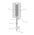
図1−3に示すように、本発明の固体酸化物型電解質燃料電池試験装置は、担体機構1と、ガス供給機構2と、燃料供給機構3と、管状蒸発器4とを備える。
As shown in FIG. 1-3, the solid oxide fuel cell test apparatus of the present invention includes a
担体機構1は、2つの対向するアノード分流板12及びカソード分流板11を有し、カソード分流板11は、アノード分流板12に相対する側にカソード集電網111とカソード電圧線112とカソード電流線113とを備え、カソード電圧線112及びカソード電流線113はカソード分流板11を通過してカソード集電網111に接続し、
また、アノード分流板12は、カソード分流板11に相対する側にアノード集電網121とアノード電圧線122とアノード電流線123とを備え、アノード電圧線122及びアノード電流線123はアノード分流板12を通過してアノード集電網121に接続する。
The
Further, the
電池ユニットBは、カソード集電網111とアノード集電網121との間に設けられ、電池ユニットBのカソードは、カソード電圧線112とカソード電流線113とに接触し、及び電池ユニットBのアノードは、アノード電圧線122とアノード電流線123とに接触する。
The battery unit B is provided between the cathode
ガス供給機構2は、担体機構1の一側に設けられ、カソード分流板11に接続されたカソードガス導管21、カソードガス導管21他端に接続された空気3方マニホールド22、及び空気3方マニホールド22の他端に接続された電池ユニットBのカソード熱電対23を具え、カソードガス導管21の外周面にカソード支持枠24を設ける。
The
燃料供給機構3は、担体機構1の他方の側に設けられて、アノード分流板12に接続されたアノードガス導管31、アノードガス導管31他端に接続された燃料3方マニホールド32、及び燃料3方マニホールド32の他端に接続された電池ユニットBのアノード熱電対33を具え、アノードガス導管31の外周面にアノード支持枠34を設ける。
The
管状蒸発器4の一端に燃料供給機構3の燃料マニホールド32の一端が接続され、かつ管状蒸発器4の他端は水管42を介して外部水源に接続され、担体機構1が高温炉A内に配置されると、高温炉で発生した熱が外部から管状蒸発器4に導入された水を加熱して水を蒸気に変換し、燃料とともに燃料3方マニホールドを介してアノードガス導管に供給される。
One end of the
上記本発明の固体酸化物型電解質燃料電池の試験装置の構成は、燃料電池発電の検出に適用可能である。実際の応用に際しては、設定温度保たれた高温炉Aの収容空間A1内に担体機構1を配置し、高温炉Aの外側に管状蒸発器4を配置し、カソード電圧線112とアノード電圧線122との間に電圧計5を接続し、およびカソード電流線113とアノード電流線123との間に検流計6を接続している。
The configuration of the test apparatus for the solid oxide fuel cell of the present invention can be applied to the detection of fuel cell power generation. In actual application, the
空気が空気入口221とガス3方マニホールド22を介してカソードガス管21に導入され、また、管状蒸発器4内の水は加熱のため高温炉Aで発生した熱を利用して、また管状蒸発器4内の多層充填材41によって水が均一に分散させられて、安定した蒸気を生成するように均一に加熱され、燃料入口431から導入される燃料と共に水蒸気が燃料3方マニホールド32を介してアノードガス導管31に導入され、水蒸気を含んだ燃料と空気とが反応のため、それぞれカソード分流板11とアノード分流板12を介して電池ユニットBで均一に分散される。
Air is introduced into the
カソード熱電対23及びアノード熱電対33は、電池ユニットBの温度を監視して炉Aの温度を適温に調整し、最後にカソード集電網111とアノード集電網121を介して、電池ユニットBのカソード及びアノードとそれぞれ接触し、そして電流が電池ユニットBから出力し、また残留空気と燃料または反応副生成物がカソード分流板11とアノード分流板12を介して直接排出される。
The
図4に示すように、実用的な応用に際しては、外部直流電源7がカソード電流線113とアノード電流線123との間に接続されており、他の構造体部分が図3と同じように示されている。
直流電源7にそれぞれ接続されたカソード電流線113とアノード電流線123を介して直流電源を供給して、電池ユニットBのカソードとアノードで逆発電反応に起こし、アノードで水素ガスを生成する。電池ユニットBは過剰なエネルギーを水素に変換し、燃料電池に使用するために想定されているような、電力オフピーク期間に自ら水素製造を生成することができる。
同時に、蒸発器4によって生成された水蒸気が電池ユニットBへのパルス電圧の影響を効果的に低減することができ、そして高い信頼性で高温電解水素生成が達成される。
As shown in FIG. 4, in a practical application, the external
A DC power supply is supplied via the cathode
At the same time, the water vapor generated by the
まとめると、本発明の固体酸化物型電解質燃料電池試験装置は、高温電解水素生成試験における水蒸気の安定供給を行って電池ユニットへの電圧パルスの悪影響を軽減し、信頼性及び有効性を改善する。 In summary, the solid oxide fuel cell test apparatus of the present invention provides a stable supply of water vapor in the high temperature electrolytic hydrogen generation test to reduce the adverse effect of the voltage pulse on the battery unit and improve reliability and effectiveness. ..
本発明の特徴および利点は、本発明の構造及び機能の詳細と共に前述の説明に記載されている事項により、制約されるものではないということが理解されるべきであり、これら開示はあくまで例示であって、詳細に関しては変更がなされ得るものであること、特に、形状、サイズ、および本発明の原理内の部品の配置等は、特許請求の範囲に表現される用語の広い一般的な意味によって解されるべきである。 It should be understood that the features and advantages of the present invention are not constrained by the matters described in the above description along with the details of the structure and function of the present invention, and these disclosures are merely exemplary. Therefore, the details can be changed, in particular, the shape, size, arrangement of parts within the principles of the present invention, etc., by the broad general meaning of the terms expressed in the claims. Should be understood.
1 担体機構
11 カソード分流板
111 ソード集電網
112 カソード電圧線
113 カソード電流線
12 アノード分流板
121 アノード集電網
122 アノード電圧線
123 アノード電流線
2 ガス供給機構
21 カソードガス導管
22 空気3方マニホールド
221 空気入口
23 カソード熱電対
24 カソード支持枠
3 燃料供給機構
31 アノードガス導管
32 燃料3方マニホールド
33 アノード熱電対
34 アノード支持枠
4 管状蒸発器
41 多層充填材
42 水管
421 制御弁
422 水入口
43 3方マニホールド
431 燃料入口
5 電圧計
6 検流計
7 直流電源
A 高温炉
A1 収容空間
B 電池ユニット
1 Carrier mechanism
11
121 Anode
421
Claims (2)
前記担体機構は、高温炉内に配置され、2つのそれぞれ対向するアノード分流板及びカソード分流板を備え、
前記カソード分流板は、前記アノード分流板に相対する側にカソード集電網とカソード電圧線とカソード電流線を備えると共に該カソード電圧線とカソード電流線は前記カソード分流板に通過して前記カソード集電網に接続され、
前記アノード分流板は、前記カソード分流板に相対する側にアノード集電網とアノード電圧線とアノード電流線を備えると共に該アノード電圧線とアノード電流線は前記アノード分流板を通過して前記アノード集電網に接続され、
前記カソード集電網とアノード集電網との間に電池ユニットが配置され、該電池ユニットのカソードが前記カソード電圧線と前記カソード電流線に接触し、かつ前記電池ユニットのアノードが前記アノード電圧線と前記アノード電流線を接触し、
前記ガス供給機構は、前記担体機構の一側に設けられて、前記カソード分流板に接続されたカソードガス導管と前記カソードガス導管の他端に接続された空気3方マニホールドと前記空気3方マニホールドの他端に接続された前記電池ユニットのカソード熱電対を具え、
前記燃料供給機構は、前記担体機構に対して前記ガス供給機構の反対側に設けられて、前記アノード分流板に接続されたアノードガス導管と前記アノードガス導管他端に接続された燃料3方マニホールド及び前記燃料3方マニホールドの他端に接続された前記電池ユニットのアノード熱電対を具え、
前記電池ユニットは、前記カソード電流線と前記アノード電流線を介して外部の直流電源に接続され、
前記管状蒸発器は、その一端に前記燃料供給機構の前記燃料3方マニホールドの一端に接続すると共に、その他端に外部の水供給源に接続される水管を設け、
前記管状蒸発器の内部には該水管から水を供給される金属網からなる多層充填材を設けて水を均一に分散させ、
上記管状蒸発器の他端側から供給されるアノードガスを該多層充填材 を通して高温炉で発生した熱により多層充填材を加熱して水を蒸発させてアノードガスに加えて水蒸気を含んだ燃料ガスとして、
前記燃料3方マニホールドを介して前記燃料供給機構に供給することを特徴とする固体酸化物型電解質燃料電池試験装置。 A solid oxide fuel cell test apparatus composed of a carrier mechanism, a gas supply mechanism, a fuel supply mechanism, and a tubular evaporator.
The carrier mechanism is arranged in a high temperature furnace and includes two opposing anode diversion plates and cathode diversion plates.
The cathode diversion plate includes a cathode current collector network, a cathode voltage line, and a cathode current line on the side facing the anode diversion plate, and the cathode voltage line and the cathode current line pass through the cathode diversion plate to the cathode current collector network. Connected to
The anode diversion plate includes an anode current collector, an anode voltage line, and an anode current line on the side facing the cathode diversion plate, and the anode voltage line and the anode current line pass through the anode diversion plate and the anode current collector network. Connected to
A battery unit is arranged between the cathode current collecting network and the anode current collecting network, the cathode of the battery unit is in contact with the cathode voltage line and the cathode current line, and the anode of the battery unit is the anode voltage line and the said. Contact the anode current line,
The gas supply mechanism is provided on one side of the carrier mechanism, and is a cathode gas conduit connected to the cathode diversion plate, an air three-way manifold connected to the other end of the cathode gas conduit, and the air three-way manifold. With a cathode thermocouple of the battery unit connected to the other end of the
The fuel supply mechanism is provided on the opposite side of the gas supply mechanism with respect to the carrier mechanism, and is a fuel three-way manifold connected to the anode gas conduit connected to the anode diversion plate and the other end of the anode gas conduit. And the anode thermocouple of the battery unit connected to the other end of the fuel three-way manifold.
The battery unit is connected to an external DC power supply via the cathode current line and the anode current line.
The tubular evaporator is provided with a water pipe connected to one end of the fuel three-way manifold of the fuel supply mechanism at one end thereof and connected to an external water supply source at the other end.
Inside the tubular evaporator, a multi-layer filler made of a metal net to which water is supplied from the water pipe is provided to uniformly disperse the water.
The tubular evaporator of the fuel gas containing steam added by the heat generated in the high temperature furnace by heating the multilayer filler to evaporate water in the anode gas through the multilayer filler anode gas supplied from the other end As ,
A solid oxide fuel cell test apparatus for supplying fuel to the fuel supply mechanism via the fuel three-way manifold.
The solid oxide fuel cell test apparatus according to claim 1, wherein the carrier mechanism supports the battery unit to be tested in a detachable manner.
Priority Applications (1)
| Application Number | Priority Date | Filing Date | Title |
|---|---|---|---|
| JP2016072187A JP6888918B2 (en) | 2016-03-31 | 2016-03-31 | Solid oxide fuel cell test equipment |
Applications Claiming Priority (1)
| Application Number | Priority Date | Filing Date | Title |
|---|---|---|---|
| JP2016072187A JP6888918B2 (en) | 2016-03-31 | 2016-03-31 | Solid oxide fuel cell test equipment |
Publications (2)
| Publication Number | Publication Date |
|---|---|
| JP2017183203A JP2017183203A (en) | 2017-10-05 |
| JP6888918B2 true JP6888918B2 (en) | 2021-06-18 |
Family
ID=60006568
Family Applications (1)
| Application Number | Title | Priority Date | Filing Date |
|---|---|---|---|
| JP2016072187A Active JP6888918B2 (en) | 2016-03-31 | 2016-03-31 | Solid oxide fuel cell test equipment |
Country Status (1)
| Country | Link |
|---|---|
| JP (1) | JP6888918B2 (en) |
Families Citing this family (2)
| Publication number | Priority date | Publication date | Assignee | Title |
|---|---|---|---|---|
| CN115508715B (en) * | 2022-08-24 | 2023-06-23 | 华北电力大学 | Flat plate type solid oxide cell partition testing device and testing method thereof |
| CN117233502B (en) * | 2023-09-15 | 2024-05-14 | 华北电力大学 | Device and method for testing zoned connector of solid oxide battery |
Family Cites Families (6)
| Publication number | Priority date | Publication date | Assignee | Title |
|---|---|---|---|---|
| JP3377683B2 (en) * | 1996-06-25 | 2003-02-17 | 三菱重工業株式会社 | Evaluation device for solid oxide fuel cell |
| JP3469071B2 (en) * | 1997-11-26 | 2003-11-25 | 関西電力株式会社 | Steam electrolysis method |
| JP2004149402A (en) * | 2002-10-10 | 2004-05-27 | Matsushita Electric Ind Co Ltd | Hydrogen generator and fuel cell system having the same |
| JP2011072894A (en) * | 2009-09-30 | 2011-04-14 | Chino Corp | Evaporator |
| TWI456230B (en) * | 2010-10-21 | 2014-10-11 | Atomic Energy Council | An open flat detecting device for solid-oxide fuel cell |
| JP5789490B2 (en) * | 2011-11-15 | 2015-10-07 | 株式会社チノー | Holder for electrochemical cell evaluation |
-
2016
- 2016-03-31 JP JP2016072187A patent/JP6888918B2/en active Active
Also Published As
| Publication number | Publication date |
|---|---|
| JP2017183203A (en) | 2017-10-05 |
Similar Documents
| Publication | Publication Date | Title |
|---|---|---|
| Ni et al. | Energy and exergy analysis of hydrogen production by a proton exchange membrane (PEM) electrolyzer plant | |
| Ito et al. | Influence of pore structural properties of current collectors on the performance of proton exchange membrane electrolyzer | |
| Ressel et al. | Performance of a vanadium redox flow battery with tubular cell design | |
| TWI559610B (en) | Solid oxide electrochemical cell testing device | |
| JP6888918B2 (en) | Solid oxide fuel cell test equipment | |
| Fu et al. | Durability Testing of a High‐Temperature Steam Electrolyzer Stack at 700° C | |
| Petitjean et al. | Performance and durability of high temperature steam electrolysis: from the single cell to short-stack scale | |
| CN110611114A (en) | Fuel cell membrane electrode rapid test equipment | |
| CN210489745U (en) | Fuel cell membrane electrode rapid test equipment | |
| Shiraki et al. | Efficiency calculations for SOFC/SOEC reversible system and evaluations of performances of button-size anode-supported cell | |
| Huang et al. | Evaluation of the waste heat and residual fuel from the solid oxide fuel cell and system power optimization | |
| Clement et al. | Measurement of localized current distribution in a vanadium redox flow battery | |
| CN106058289B (en) | A kind of temperature control microbiological fuel cell | |
| TWI708955B (en) | Solid oxide electrolysis cell test and hydrogen generating device | |
| Jasiński et al. | In situ infrared thermography of full-scale solid oxide fuel cell | |
| US20170335475A1 (en) | Solid oxide electrolysis cell with test apparatus | |
| US20120040263A1 (en) | Fuel Cell Device | |
| Chun et al. | Investigation of fin based oxygen supply modules on the performance of air-breathing polymer electrolyte membrane fuel cells | |
| Mu et al. | The development and performance analysis of all-China-made PEM fuel cell unit and 1 kW level fuel cell stack | |
| Willamson et al. | Evaluation of fin structure effects on a heated air-breathing polymer electrolyte membrane (PEM) fuel cell | |
| Liu et al. | The impacts of microporous layer degradation on liquid water distributions in polymer electrolyte membrane fuel cells using synchrotron imaging | |
| JP2011171003A (en) | Holder for evaluation of electrochemical cell | |
| Schiller et al. | Solid oxide steam electrolysis with integration of solar heat | |
| Wu et al. | Simultaneous characterizations of segmented electrochemical characteristics and temperature distribution in the hythane-fueled direct internal reforming solid oxide fuel cell | |
| JP3226768U (en) | Small test equipment for evaluating fuel cell materials |
Legal Events
| Date | Code | Title | Description |
|---|---|---|---|
| A621 | Written request for application examination |
Free format text: JAPANESE INTERMEDIATE CODE: A621 Effective date: 20180816 |
|
| A977 | Report on retrieval |
Free format text: JAPANESE INTERMEDIATE CODE: A971007 Effective date: 20190724 |
|
| A131 | Notification of reasons for refusal |
Free format text: JAPANESE INTERMEDIATE CODE: A131 Effective date: 20190729 |
|
| A521 | Request for written amendment filed |
Free format text: JAPANESE INTERMEDIATE CODE: A523 Effective date: 20191017 |
|
| A131 | Notification of reasons for refusal |
Free format text: JAPANESE INTERMEDIATE CODE: A131 Effective date: 20200323 |
|
| A521 | Request for written amendment filed |
Free format text: JAPANESE INTERMEDIATE CODE: A523 Effective date: 20200525 |
|
| A131 | Notification of reasons for refusal |
Free format text: JAPANESE INTERMEDIATE CODE: A131 Effective date: 20201102 |
|
| A521 | Request for written amendment filed |
Free format text: JAPANESE INTERMEDIATE CODE: A523 Effective date: 20201126 |
|
| A521 | Request for written amendment filed |
Free format text: JAPANESE INTERMEDIATE CODE: A523 Effective date: 20201207 |
|
| TRDD | Decision of grant or rejection written | ||
| A01 | Written decision to grant a patent or to grant a registration (utility model) |
Free format text: JAPANESE INTERMEDIATE CODE: A01 Effective date: 20210510 |
|
| A61 | First payment of annual fees (during grant procedure) |
Free format text: JAPANESE INTERMEDIATE CODE: A61 Effective date: 20210520 |
|
| R150 | Certificate of patent or registration of utility model |
Ref document number: 6888918 Country of ref document: JP Free format text: JAPANESE INTERMEDIATE CODE: R150 |
|
| R250 | Receipt of annual fees |
Free format text: JAPANESE INTERMEDIATE CODE: R250 |