JP6888677B2 - Threaded joints for oil country tubular goods - Google Patents
Threaded joints for oil country tubular goods Download PDFInfo
- Publication number
- JP6888677B2 JP6888677B2 JP2019530840A JP2019530840A JP6888677B2 JP 6888677 B2 JP6888677 B2 JP 6888677B2 JP 2019530840 A JP2019530840 A JP 2019530840A JP 2019530840 A JP2019530840 A JP 2019530840A JP 6888677 B2 JP6888677 B2 JP 6888677B2
- Authority
- JP
- Japan
- Prior art keywords
- screw
- joint
- pin
- box
- pipe
- Prior art date
- Legal status (The legal status is an assumption and is not a legal conclusion. Google has not performed a legal analysis and makes no representation as to the accuracy of the status listed.)
- Active
Links
- 239000003129 oil well Substances 0.000 claims description 24
- 230000002093 peripheral effect Effects 0.000 claims description 17
- 229910000831 Steel Inorganic materials 0.000 claims description 15
- 239000010959 steel Substances 0.000 claims description 15
- 239000002184 metal Substances 0.000 claims description 14
- 238000007789 sealing Methods 0.000 claims description 13
- 239000012530 fluid Substances 0.000 claims description 6
- 239000003921 oil Substances 0.000 description 16
- 238000013461 design Methods 0.000 description 11
- 238000004519 manufacturing process Methods 0.000 description 7
- 238000012360 testing method Methods 0.000 description 7
- 238000010276 construction Methods 0.000 description 6
- 238000012545 processing Methods 0.000 description 6
- 238000005520 cutting process Methods 0.000 description 4
- 238000010008 shearing Methods 0.000 description 4
- 238000011156 evaluation Methods 0.000 description 3
- 238000003754 machining Methods 0.000 description 3
- 230000003014 reinforcing effect Effects 0.000 description 3
- 230000000052 comparative effect Effects 0.000 description 2
- 238000011161 development Methods 0.000 description 2
- 230000018109 developmental process Effects 0.000 description 2
- 239000007789 gas Substances 0.000 description 2
- 238000000034 method Methods 0.000 description 2
- 238000005096 rolling process Methods 0.000 description 2
- 230000002411 adverse Effects 0.000 description 1
- 230000004323 axial length Effects 0.000 description 1
- 238000009412 basement excavation Methods 0.000 description 1
- 238000005452 bending Methods 0.000 description 1
- 230000006835 compression Effects 0.000 description 1
- 238000007906 compression Methods 0.000 description 1
- 238000007796 conventional method Methods 0.000 description 1
- 230000008878 coupling Effects 0.000 description 1
- 238000010168 coupling process Methods 0.000 description 1
- 238000005859 coupling reaction Methods 0.000 description 1
- 239000010779 crude oil Substances 0.000 description 1
- 238000010586 diagram Methods 0.000 description 1
- 238000005553 drilling Methods 0.000 description 1
- 230000000694 effects Effects 0.000 description 1
- 239000002343 natural gas well Substances 0.000 description 1
- 238000005457 optimization Methods 0.000 description 1
- 239000003208 petroleum Substances 0.000 description 1
- 239000002436 steel type Substances 0.000 description 1
Images

Classifications
-
- F—MECHANICAL ENGINEERING; LIGHTING; HEATING; WEAPONS; BLASTING
- F16—ENGINEERING ELEMENTS AND UNITS; GENERAL MEASURES FOR PRODUCING AND MAINTAINING EFFECTIVE FUNCTIONING OF MACHINES OR INSTALLATIONS; THERMAL INSULATION IN GENERAL
- F16L—PIPES; JOINTS OR FITTINGS FOR PIPES; SUPPORTS FOR PIPES, CABLES OR PROTECTIVE TUBING; MEANS FOR THERMAL INSULATION IN GENERAL
- F16L15/00—Screw-threaded joints; Forms of screw-threads for such joints
- F16L15/001—Screw-threaded joints; Forms of screw-threads for such joints with conical threads
-
- E—FIXED CONSTRUCTIONS
- E21—EARTH DRILLING; MINING
- E21B—EARTH DRILLING, e.g. DEEP DRILLING; OBTAINING OIL, GAS, WATER, SOLUBLE OR MELTABLE MATERIALS OR A SLURRY OF MINERALS FROM WELLS
- E21B17/00—Drilling rods or pipes; Flexible drill strings; Kellies; Drill collars; Sucker rods; Cables; Casings; Tubings
- E21B17/02—Couplings; joints
- E21B17/04—Couplings; joints between rod or the like and bit or between rod and rod or the like
- E21B17/042—Threaded
-
- F—MECHANICAL ENGINEERING; LIGHTING; HEATING; WEAPONS; BLASTING
- F16—ENGINEERING ELEMENTS AND UNITS; GENERAL MEASURES FOR PRODUCING AND MAINTAINING EFFECTIVE FUNCTIONING OF MACHINES OR INSTALLATIONS; THERMAL INSULATION IN GENERAL
- F16L—PIPES; JOINTS OR FITTINGS FOR PIPES; SUPPORTS FOR PIPES, CABLES OR PROTECTIVE TUBING; MEANS FOR THERMAL INSULATION IN GENERAL
- F16L15/00—Screw-threaded joints; Forms of screw-threads for such joints
- F16L15/04—Screw-threaded joints; Forms of screw-threads for such joints with additional sealings
-
- F—MECHANICAL ENGINEERING; LIGHTING; HEATING; WEAPONS; BLASTING
- F16—ENGINEERING ELEMENTS AND UNITS; GENERAL MEASURES FOR PRODUCING AND MAINTAINING EFFECTIVE FUNCTIONING OF MACHINES OR INSTALLATIONS; THERMAL INSULATION IN GENERAL
- F16L—PIPES; JOINTS OR FITTINGS FOR PIPES; SUPPORTS FOR PIPES, CABLES OR PROTECTIVE TUBING; MEANS FOR THERMAL INSULATION IN GENERAL
- F16L15/00—Screw-threaded joints; Forms of screw-threads for such joints
- F16L15/06—Screw-threaded joints; Forms of screw-threads for such joints characterised by the shape of the screw-thread
Description
本発明は、油井やガス井の探査や生産に使用されるチュービングおよびケーシングを包含する油井管を接続する油井管用ねじ継手であり、特に加工時間および施工時間を低減させた油井管用ねじ継手に関する。 The present invention relates to a threaded joint for an oil well pipe that connects an oil well pipe including a tubing and a casing used for exploration and production of an oil well or a gas well, and particularly relates to a threaded joint for an oil well pipe in which processing time and construction time are reduced.
管用ねじ継手は、油井管など産油産業設備に使用される鋼管の接続に広く使用されている。オイルやガスの探索や生産に使用される鋼管の接続には、従来、API(米国石油協会)規格に規定された標準的な管用ねじ継手が典型的には使用されてきた。 Threaded pipe joints are widely used to connect steel pipes used in oil production equipment such as oil country tubular goods. Traditionally, standard threaded pipe fittings specified in API (American Petroleum Institute) standards have been typically used to connect steel pipes used in the search and production of oils and gases.
近年、原油や天然ガスの井戸は深井戸化が進み、垂直井から水平井や傾斜井等が増えていることから、掘削および生産環境はより苛酷になっている。また、海洋や極地などの劣悪な環境での井戸の開発が増加していることなどから、耐圧縮性能、耐曲げ性能および外圧シール性能など、管用ねじ継手への要求性能は多様化している。このような要求性能のために、プレミアムジョイントと呼ばれる高性能の特殊な管用ねじ継手を使用することが増加している。 In recent years, crude oil and natural gas wells have become deeper, and the number of vertical wells, horizontal wells, and inclined wells has increased, and the drilling and production environment has become more severe. In addition, due to the increasing development of wells in adverse environments such as the ocean and polar regions, the required performance for pipe threaded joints, such as compression resistance, bending resistance, and external pressure sealing performance, is diversifying. Due to such required performance, the use of high-performance special threaded joints for pipes called premium joints is increasing.
また、井戸開発時の掘削量を低減するためには、井戸をスリムにする必要がある。そのため、プレミアムジョイントの中でも、カップリング部材を介さずに管(パイプともいう)同士を直接接続するインテグラル形式の管用ねじ継手への要求も高まっている。 In addition, in order to reduce the amount of excavation during well development, it is necessary to make the well slim. Therefore, among premium joints, there is an increasing demand for integral type threaded pipe joints that directly connect pipes (also called pipes) without using a coupling member.
プレミアムジョイントは、通常、各パイプの管端側に、テーパねじと、メタルタッチシール部を備える。これらは、パイプの一端側に設けられた雄ねじ部であるピンと、パイプの一端側に設けられた上記雄ねじ部に螺合または嵌合する雌ねじ部であるボックスとを構成する各要素である。これらの要素は、継手(管用ねじ継手の意、以下同じ)の締付け時に、雄のテーパねじと雌のテーパねじ、雄のメタルタッチシール部と雌のメタルタッチシール部が、それぞれ対面し合うように設計される。なお、テーパねじは、継手をタイトに固定するために必要である。メタルタッチシール部は、このメタルタッチシール部の領域でボックスとピンとの金属接触によりシール性を確保する。 Premium joints are usually provided with a taper screw and a metal touch seal on the pipe end side of each pipe. These are each element that constitutes a pin that is a male threaded portion provided on one end side of the pipe and a box that is a female threaded portion that is screwed or fitted to the male threaded portion provided on one end side of the pipe. These elements are such that when tightening a joint (meaning a threaded joint for pipes, the same applies hereinafter), the male taper screw and the female taper screw, and the male metal touch seal part and the female metal touch seal part face each other. Designed to. The taper screw is necessary to fix the joint tightly. The metal touch seal portion secures the sealing property by metal contact between the box and the pin in the area of the metal touch seal portion.
インテグラル形式の管用ねじ継手(以下、インテグラル継手ともいう)では、上記メタルタッチシール部は、軸方向(管軸方向の意、以下同じ)の一つまたは二つ以上の箇所に設けられる。少なくとも1箇所のメタルタッチシール部は、ピンのテーパねじのピン先端側ねじ端に連接したねじ無し部(以下、ノーズという)の外周面、およびボックスのテーパねじのボックス後端側ねじ端に連接したねじ無し部(以下、ノーズ穴という)の内周面に設けられる。 In an integral type threaded joint for pipes (hereinafter, also referred to as an integral joint), the metal touch seal portion is provided at one or more positions in the axial direction (meaning in the pipe axial direction, hereinafter the same). At least one metal touch seal portion is connected to the outer peripheral surface of the unthreaded portion (hereinafter referred to as the nose) connected to the pin tip side screw end of the pin taper screw and to the box rear end side screw end of the box taper screw. It is provided on the inner peripheral surface of the screwless portion (hereinafter referred to as the nose hole).
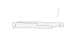
インテグラル継手の従来技術として、特許文献1に記載されたパイプ用ねじ付き継手1(管ねじ継手)を図2に示す。特許文献1に記載の発明の課題は、適当な剛性を維持し、改良されたシールを設けたパイプ用ねじ付き継手を生産すること、高荷重に対する、特に圧縮荷重に対する継手の構造的抵抗(特性)を改善すること、および上記特性がシール機能に影響しないようにすることである。そして、特許文献1に記載の発明では、上記ボックス3の先端側非ねじ面のメタルタッチシール部からボックス最先端まで突き出た補強セクションを設け、この補強セクションの長さ、あるいはさらに壁厚(肉厚)を規定し、かつ、上記ボックスの補強セクション全長が相対するピン2の後端側のパイプ(素管部)と接触を生じないようにしてある。
FIG. 2 shows a threaded joint 1 (pipe threaded joint) for a pipe described in Patent Document 1 as a conventional technique for an integral joint. The subject of the invention described in Patent Document 1 is to produce a threaded joint for pipes which maintains appropriate rigidity and is provided with an improved seal, and structural resistance (characteristics) of the joint to a high load, particularly to a compressive load. ), And to prevent the above properties from affecting the sealing function. Then, in the invention described in Patent Document 1, a reinforcing section protruding from the metal touch seal portion of the non-threaded surface on the tip side of the box 3 to the tip of the box is provided, and the length of the reinforcing section or the wall thickness (wall thickness) is further increased. The thickness) is specified, and the total length of the reinforcing section of the box is set so as not to cause contact with the pipe (bare pipe portion) on the rear end side of the
しかしながら、上記の特許文献1に記載の技術では、継手のねじ長さの適正化について言及されていない。生産性と継手の剪断破壊強度を両立するようなねじ長さの適正化については改善の余地があった。 However, the technique described in Patent Document 1 does not mention the optimization of the thread length of the joint. There was room for improvement in optimizing the thread length so as to achieve both productivity and shear fracture strength of the joint.
通常、油井管は、継手部(上記雄ねじ部と上記雌ねじ部を総称していう)を有する管を継手部で複数直列に接続して井戸に装入する。この状態では、地上に近い管ほど継手部に相対的に大きな引張負荷が作用する。そのため、油井管用ねじ継手には、疲労破壊や引張破断などの剪断破壊を回避できる強度を有することが重要な継手性能の一つとして要求される。継手部の強度を確保する方法として、継手部のねじ長さをある程度長く設けることが求められる。一般的に、継手部が剪断破壊を回避できる強度を備えるためには、ねじ部の剪断破壊強度が継手部の引張破断強度を超える必要があり、ねじ部剪断応力が継手部の引張応力の1/√3倍以下となるように設計する必要がある。なお、継手部のねじ長さとは、継手部における雄ねじ部と雌ねじ部が嵌め合い状態にある部位の全長を指す。 Usually, in an oil well pipe, a pipe having a joint portion (the male screw portion and the female screw portion are collectively referred to) are connected in series at the joint portion and charged into a well. In this state, a pipe closer to the ground exerts a relatively large tensile load on the joint portion. Therefore, the threaded joint for oil country tubular goods is required to have strength that can avoid shear fracture such as fatigue fracture and tensile fracture as one of the important joint performances. As a method of ensuring the strength of the joint portion, it is required to provide the screw length of the joint portion to a certain length. Generally, in order for the joint portion to have a strength that can avoid shear fracture, the shear fracture strength of the thread portion must exceed the tensile fracture strength of the joint portion, and the shear stress of the thread portion is 1 of the tensile stress of the joint portion. It is necessary to design so that it is / √3 times or less. The thread length of the joint portion refers to the total length of the portion of the joint portion in which the male screw portion and the female screw portion are in a fitted state.
しかし、剪断破壊強度を確保するために継手部のねじ長さを極端に長くすることは、鋼管(素管)にねじ切削加工あるいは転造加工を施す際に、ねじ長さに比例して加工時間が増加する問題がある。また、ねじを締め付ける際に、ねじを締めつける施工時間が増加する問題もある。よって、生産性の低下や、製造コストの上昇を招く。 However, making the thread length of the joint part extremely long in order to secure the shear fracture strength is processed in proportion to the thread length when thread cutting or rolling is performed on the steel pipe (bare pipe). There is a problem that time increases. Further, when tightening the screw, there is a problem that the construction time for tightening the screw increases. Therefore, the productivity is lowered and the manufacturing cost is raised.
本発明は係る問題に鑑み、継手部のねじ長さの適正化を図るとともに、加工時間および施工時間を低減させた油井管用ねじ継手を提供することを目的とする。 In view of the above problems, it is an object of the present invention to provide a threaded joint for an oil well pipe in which the thread length of the joint portion is optimized and the processing time and the construction time are reduced.
本発明者らは、上記の課題を解決するために鋭意検討した。 The present inventors have diligently studied to solve the above-mentioned problems.
上述のように、油井管は、管同士を継手部で複数直列に接続して井戸に装入するため、地上に近い管ほど継手部には大きな引張負荷が作用する。継手部では、ピン破断、ボックス破断などを生じる場合がある。そのため、継手部が剪断破壊を回避できる強度を有することは、重要な継手性能の一つとして要求される。この要求に対し、通常は上記強度を確保するために継手部のねじ長さを長く設計することで対応する。そのため、一般的には安全を見て(考慮して)ねじ長さを過剰に長くした設計となっている。そこで、本発明者らは、継手部のねじ部(雄雌のテーパねじ部分を指す)が剪断破壊されないだけの必要最低限のねじ長さを有するような設計に着眼し、生産性と継手の剪断破壊強度との両立を可能とする油井管用ねじ継手について鋭意検討を行った。 As described above, in the oil well pipe, since a plurality of pipes are connected in series at the joint portion and charged into the well, a larger tensile load acts on the joint portion as the pipe is closer to the ground. In the joint portion, pin breakage, box breakage, etc. may occur. Therefore, it is required as one of the important joint performances that the joint portion has the strength to avoid shear fracture. This requirement is usually met by designing a long screw length of the joint portion in order to secure the above strength. Therefore, in general, the screw length is designed to be excessively long in consideration of safety. Therefore, the present inventors focused on a design in which the threaded portion of the joint portion (pointing to the male and female tapered threaded portions) has the minimum necessary thread length so as not to be fractured by shearing, and the productivity and the joint We conducted a diligent study on threaded joints for oil well pipes that can achieve both shear fracture strength.
その結果、継手に引張応力を作用させたときに雄雌のテーパねじに作用する剪断応力と継手の危険断面に作用する引張応力の比が所定値以下となるように必要最低限のねじ長さLmin(mm)を規定することにより、ねじ部での剪断破壊を防止できることを知見した。As a result, the minimum required screw length is such that the ratio of the shear stress acting on the male and female tapered threads and the tensile stress acting on the dangerous cross section of the joint is less than a predetermined value when a tensile stress is applied to the joint. It was found that by specifying L min (mm), shear failure at the threaded portion can be prevented.
本発明は上述の知見に基づいてなされたものであり、以下を要旨とするものである。
[1] 鋼管の一端に雄のテーパねじである雄ねじ部が設けられたピンと、
鋼管の一端に前記雄ねじ部と嵌合する雌のテーパねじである雌ねじ部が設けられたボックスとを有し、
前記ピンと前記ボックスとが金属接触して流体をシールする構造を、前記ピンの管端側の外周面側シール部および前記ボックスの管端側の内周面側シール部の少なくとも1箇所に備えるインテグラル式の油井管用ねじ継手であり、
前記雄のテーパねじおよび前記雌のテーパねじのねじ列におけるねじ長さL(mm)の最小値Lmin(mm)が(1)式により定義され、
前記ねじ列におけるねじ長さL(mm)が(2)式を満足する、
油井管用ねじ継手。
Lmin=((t×(D−t))/(αt×Dt/√3))×継手効率 ・・・・(1)
Lmin×1.0≦L≦Lmin×2.5 ・・・・(2)
ここで、t:ボックスおよびピンの未加工部である素管部の管厚(mm)、
D:ボックスおよびピンの未加工部である素管部の管径(mm)、
αt:ねじ長さLに対するねじ有効長さの比であり、
ねじ有効長さはボックスまたはピンのうち短い側を選択、
Dt:ボックスまたはピンのうちねじ有効長さが短い側のテーパね
じにおけるねじ谷の平均ねじ径 (mm)、
継手効率:継手部の引張強度/素管部の引張強度、
とする。The present invention has been made based on the above findings, and the gist of the present invention is as follows.
[1] A pin provided with a male threaded portion, which is a male tapered thread, at one end of a steel pipe.
One end of the steel pipe has a box provided with a female threaded portion which is a female tapered thread that fits with the male threaded portion.
Integra that provides a structure in which the pin and the box make metal contact to seal the fluid at at least one of the outer peripheral surface side sealing portion on the pipe end side of the pin and the inner peripheral surface side sealing portion on the pipe end side of the box. It is a screw joint for oil well pipes of the type
The minimum value L min (mm) of the screw length L (mm) in the thread row of the male taper screw and the female taper screw is defined by Eq. (1).
The screw length L (mm) in the screw row satisfies the equation (2).
Threaded joints for oil country tubular goods.
L min = ((t × (Dt)) / (α t × D t / √3)) × joint efficiency ・ ・ ・ ・ (1)
L min x 1.0 ≤ L ≤ L min x 2.5 ... (2)
Here, t: the pipe thickness (mm) of the raw pipe portion which is the unprocessed portion of the box and the pin,
D: Tube diameter (mm) of the raw tube part, which is the unprocessed part of the box and pin,
α t : The ratio of the effective screw length to the screw length L.
Select the shorter side of the box or pin for the effective screw length,
D t : The taper on the side of the box or pin where the effective screw length is short.
Average thread diameter of thread valley (mm),
Joint efficiency: Tensile strength of joint / Tensile strength of raw pipe,
And.
なお、本発明において、必要最低限のねじ長さ(Lmin(mm))とは、ねじ部が剪断破壊を回避できる強度を備えるために、設計上必要とされる継手部のねじ長さの最小値(下限値)を指す。
また、継手部のねじ長さ(L(mm))とは、継手部を螺合締結した際に、継手部のうち雄ねじ部と雌ねじ部とが噛み合っている部分(ねじ嵌合部)の長さ(すなわち、雄のテーパねじおよび雌のテーパねじのねじ列におけるねじ長さ)を指す。
また、ねじ有効長さとは、上記ねじ嵌合部において、雄ねじ部および雌ねじ部のねじ山の底面をそれぞれについて合算した部分の軸方向長さの総和であり、雄ねじ部および雌ねじ部についてそれぞれ算出される。
また、ねじ有効長さ比(αt)とは、ねじ長さLに対するねじ有効長さの比であり、ねじ有効長さはボックスまたはピンのうち短い側が選択される。In the present invention, the minimum required screw length (L min (mm)) is the screw length of the joint portion required by design in order for the threaded portion to have strength to avoid shear fracture. Refers to the minimum value (lower limit value).
Further, the screw length (L (mm)) of the joint portion is the length of the portion (screw fitting portion) of the joint portion in which the male screw portion and the female screw portion are engaged when the joint portion is screwed and fastened. (Ie, the thread length in the thread row of the male and female tapered threads).
The effective screw length is the sum of the axial lengths of the male-threaded portion and the female-threaded thread bottoms of the male-threaded portion and the female-threaded portion in the screw fitting portion, and is calculated for the male-threaded portion and the female-threaded portion, respectively. To.
The effective screw length ratio (α t ) is the ratio of the effective screw length to the screw length L, and the shorter side of the box or pin is selected as the effective screw length.
本発明によれば、継手部のねじ長さの適正化を図るとともに、加工時間および施工時間を低減させた油井管用ねじ継手を得ることができる。 According to the present invention, it is possible to obtain a threaded joint for an oil well pipe in which the thread length of the joint portion is optimized and the processing time and the construction time are reduced.
以下、図1を参照して、本発明の油井管用ねじ継手1について説明する。なお、本発明は以下の実施形態に限定されない。図1は、本発明の一実施形態を説明する油井管用ねじ継手1の管軸方向の断面図であり、ピン2とボックス3とが締結(嵌合)された部分とその周辺を示す断面図である。なお、図1は、後述する(1)式および(2)式の説明図でもある。
本発明の油井管用ねじ継手1は、鋼管の一端に雄のテーパねじである雄ねじ部4が設けられたピン2と、鋼管の一端に雄ねじ部4と嵌合する雌のテーパねじである雌ねじ部5が設けられたボックス3とを有する。また、ピン2とボックス3が金属接触して流体をシールする構造を、ピン2の管端側の外周面側シール部9およびボックス3の管端側の内周面側シール部10の少なくとも1箇所に備える、インテグラル式の油井管用ねじ継手1である。雄雌のテーパねじのねじ列におけるねじ長さL(mm)の最小値Lmin(mm)は、後述する(1)式により定義され、かつ、ねじ列におけるねじ長さL(mm)は、後述する(2)式を満足する。Hereinafter, the threaded joint 1 for an oil well pipe of the present invention will be described with reference to FIG. The present invention is not limited to the following embodiments. FIG. 1 is a cross-sectional view of a threaded joint 1 for an oil well pipe for explaining an embodiment of the present invention in the pipe axial direction, and is a cross-sectional view showing a portion where a
The threaded joint 1 for an oil well pipe of the present invention has a
まず、本発明の油井管用ねじ継手1の構成について説明する。 First, the configuration of the threaded joint 1 for oil country tubular goods 1 of the present invention will be described.
図1に示すように、本発明の油井管用ねじ継手1は、ピン2とボックス3により鋼管を接続する。油井管用ねじ継手1は、ピン2とボックス3がねじ結合により結合されたねじ継手(プレミアムジョイント)である。また、油井管用ねじ継手1は、ピン2とボックス3により鋼管同士を直接接続するインテグラル式ねじ継手である。
As shown in FIG. 1, the oil country tubular goods threaded joint 1 of the present invention connects a steel pipe with a
ピン2には、鋼管の一端に雄のテーパねじである雄ねじ部4が設けられている。ボックス3には、鋼管の一端に雄ねじ部4と嵌合または螺合する雌のテーパねじである雌ねじ部5が設けられている。なお、本発明では、図1に示すように、雄ねじ部4および後述する雄側のノーズ15の周辺を含めた領域をピン2と称する。雌ねじ部5および後述する雌側のノーズ穴16の周辺を含めた領域をボックス3と称する。
The
油井管用ねじ継手1は、ピン2とボックス3とが金属接触して流体をシールする構造を有する。図1に示す油井管用ねじ継手1の場合には、雄ねじ部4の管端側(図1中、ねじ継手軸αに平行なX軸の正方向側)の外周面側シール部9と、雌ねじ部5の管端側(図1中、X軸の負方向側)の内周面側シール部10の2箇所に、シール構造を有する。
The oil country tubular goods threaded joint 1 has a structure in which the
例えば、外周面側シール部9は、継手の締付け時に、ノーズ15(ピン2の先端側のねじ端に連接したねじ無し部)とノーズ穴16(ボックス3の奥端側のねじ端に連接したねじ無し部)のメタルタッチシール部同士が接触して、管内側の流体がテーパねじの領域に進入することを防止するシール面を形成する。 For example, the outer peripheral surface side seal portion 9 is connected to the nose 15 (the unthreaded portion connected to the screw end on the tip side of the pin 2) and the nose hole 16 (the screw end on the back end side of the box 3) when the joint is tightened. The metal touch seal portions of the screwless portion) come into contact with each other to form a sealing surface that prevents the fluid inside the pipe from entering the tapered screw region.
内周面側シール部10は、ピン2の奥端側のねじ端に連接したねじ無し部の外周面(便宜上、ピン奥端側非ねじ面という)、および、ボックス3の先端側のねじ端に連接したねじ無し部の内周面(便宜上、ボックス先端側非ねじ面という)に設けられる。内周面側シール部10は、ねじ継手の締付け時に、ピン奥端側非ねじ面とボックス先端側非ねじ面のシール部同士が接触して、管外側の流体がテーパねじの領域に進入することを防止するシール面を形成する。
The inner peripheral surface side sealing portion 10 includes an outer peripheral surface of a screwless portion (referred to as a non-threaded surface on the back end side of the pin) connected to a screw end on the back end side of the
その他、油井管用ねじ継手1は、ピン2の先端にショルダ部11を有してもよい。この場合には、図1に示すように、ピン2側のショルダ部11に当接するショルダ部12もボックス3に設けられる。
In addition, the oil country tubular goods threaded joint 1 may have a shoulder portion 11 at the tip of the
なお、素管部とは、ボックス3における雌ねじ部5以外の管本体の領域(ボックスの未加工部7)、および、ピン2における雄ねじ部4以外の管本体の領域(ピンの未加工部6)をそれぞれ指す。ピン2およびボックス3の未加工部6、7は、いずれも円筒形状である。
The raw pipe portion is a region of the pipe body other than the
次に、図1を参照して、本発明の油井管用ねじ継手1のねじ列17における、ねじ長さL(mm)とねじ長さの最小値Lmin(mm)の関係について説明する。 Next, with reference to FIG. 1, the relationship between the screw length L (mm) and the minimum value L min (mm) of the screw length in the
本発明の油井管用ねじ継手1は、継手部のねじ部(雄雌のテーパねじ部分を指す)が剪断破壊されない継手強度を有し、さらにその引張強度を満たす必要最低限のねじ長さを有するように設計することが重要である。そのため、本発明では、強度および寸法の制約の観点より、ねじ長さの許容範囲を次のように決定する。 The threaded joint 1 for an oil well pipe of the present invention has a joint strength in which the threaded portion of the joint portion (pointing to a male and female tapered threaded portion) is not fractured by shearing, and further has a minimum required thread length that satisfies the tensile strength. It is important to design so that. Therefore, in the present invention, the allowable range of the screw length is determined as follows from the viewpoint of strength and dimensional restrictions.
雄雌のテーパねじのねじ列17におけるねじ長さL(mm)の下限値、すなわち最小値Lmin(mm)は、以下の(1)式により定義される。さらに、ねじ列17におけるねじ長さL(mm)は、以下の(2)式を満足する必要がある。
Lmin=((t×(D−t))/(αt×Dt/√3))×継手効率 ・・・・(1)
Lmin×1.0≦L≦Lmin×2.5 ・・・・(2)
ここで、t:ボックスおよびピンの未加工部である素管部の管厚(mm)、
D:ボックスおよびピンの未加工部である素管部の管径(mm)、
αt:ねじ長さLに対するねじ有効長さの比であり、
ねじ有効長さはボックスまたはピンのうち短い側を選択
Dt:ボックスまたはピンのうちねじ有効長さが短い側のテーパね
じにおけるねじ谷の平均ねじ径(mm)、
継手効率:継手部の引張強度/素管部の引張強度、
とする。The lower limit of the screw length L (mm) in the
L min = ((t × (Dt)) / (α t × D t / √3)) × joint efficiency ・ ・ ・ ・ (1)
L min x 1.0 ≤ L ≤ L min x 2.5 ... (2)
Here, t: the pipe thickness (mm) of the raw pipe portion which is the unprocessed portion of the box and the pin,
D: Tube diameter (mm) of the raw tube part, which is the unprocessed part of the box and pin,
α t : The ratio of the effective screw length to the screw length L.
Select the shorter side of the box or pin for the effective screw length
D t : The taper on the side of the box or pin where the effective screw length is short.
Average thread diameter (mm) of the thread valley at the same time,
Joint efficiency: Tensile strength of joint / Tensile strength of raw pipe,
And.
αtはねじ形状のデザインにより決定される。ピンとボックスでねじ底の幅が違うデザインとした場合には、ねじ底の幅が狭い方の形状において有効長さが短くなる。ねじ山の頂部の幅と底部の幅を比較して底部の幅の方が大きいデザイン、例えば台形ねじ、においては、αtは大きくなる傾向にある。逆に、ねじ山の頂部の幅と底部の幅を比較して底部の幅の方が小さいデザイン、例えばウェッジねじ、においては、αtは小さくなる傾向にある。α t is determined by the screw shape design. If the pin and the box are designed with different screw bottom widths, the effective length will be shorter in the shape with the narrower screw bottom width. In a design in which the width of the bottom is larger than the width of the top of the thread and the width of the bottom, for example, a trapezoidal thread, α t tends to be large. On the contrary, in a design in which the width of the bottom is smaller than the width of the top of the thread and the width of the bottom, for example, a wedge screw, α t tends to be smaller.
ねじ長さL(mm)が、上記(2)式の(Lmin×1.0≦L)を満足しない場合、継手引張強度以下の管軸方向引張負荷により、ねじ部が剪断破壊される可能性がある。好ましくは、Lmin×1.25≦Lとする。一方、ねじ長さL(mm)が、上記(2)式の(L≦Lmin×2.5)を満足しない場合、十分に短いねじ長さの設計とは言えず、本発明の効果である加工性および生産性に優れたねじ継手であるとは言えなくなる。好ましくは、L≦Lmin×2.0とする。When the thread length L (mm) does not satisfy (L min × 1.0 ≦ L) of the above equation (2), the threaded portion may be fractured by shearing due to a tensile load in the pipe axial direction equal to or less than the joint tensile strength. There is sex. Preferably, L min × 1.25 ≦ L. On the other hand, when the screw length L (mm) does not satisfy (L ≦ L min × 2.5) of the above equation (2), it cannot be said that the design has a sufficiently short screw length, and the effect of the present invention is effective. It cannot be said that it is a threaded joint having a certain workability and productivity. Preferably, L ≦ L min × 2.0.
なお、例えば図1に示す油井管用ねじ継手1の場合、ねじ列17とは、ピン2とボックス3のそれぞれに設けられた上記テーパねじの領域を指す。
また、ねじ長さL(mm)とは、後述する通り、ピン2の危険断面14の位置からボックス3の危険断面13の位置までの長さを指す。
また、ねじ長さLの最小値Lmin(mm)とは、上記(1)で定義されるねじ長さLの必要最低限の長さを指す。
また、素管部の管厚t(mm)とは、図1に示すように、ピン未加工部6およびボックス未加工部7(素管部)の管厚を指す。素管部の管径D(mm)とは、ピン未加工部6およびボックス未加工部7(素管部)の管径を指す。Dt(mm)とは、ボックスまたはピンのうちねじ有効長さが短い側のテーパねじにおけるねじ谷の平均ねじ径を指す。For example, in the case of the oil country tubular goods screw joint 1 shown in FIG. 1, the
Further, the screw length L (mm) refers to the length from the position of the
Further, the minimum value L min (mm) of the screw length L refers to the minimum necessary length of the screw length L defined in (1) above.
Further, the pipe thickness t (mm) of the raw pipe portion refers to the pipe thickness of the pin unprocessed portion 6 and the box unprocessed portion 7 (raw pipe portion) as shown in FIG. The pipe diameter D (mm) of the raw pipe portion refers to the pipe diameter of the pin raw portion 6 and the box raw portion 7 (raw pipe portion). D t (mm) refers to the average thread diameter of the thread valley of the taper thread on the side of the box or pin where the effective thread length is short.
ここで、必要最低限のねじ長さ(すなわち、ねじ長さの最小値Lmin)を求めるための(1)式について説明する。Here, the equation (1) for obtaining the minimum required screw length (that is, the minimum value L min of the screw length) will be described.
継手強度(ねじ継手1の引張強度)は、ピン2およびボックス3の各危険断面13、14(図1を参照)のうち、断面積が小さい部位により決定される。ここで、危険断面とは、継手部の引張負荷状態において最も破断が発生し易い管軸直交断面を指す。
The joint strength (tensile strength of the screw joint 1) is determined by a portion of the
例えば、図1に示す油井管用ねじ継手1の場合、ボックス3の危険断面13として、雌ねじ部5側のねじ列17の領域のうち、第一ねじ山のロードフランク面に位置する断面を採用する。また、ピン2の危険断面14として、雄ねじ部4側のねじ列17の領域のうち、第二ねじ山のロードフランク面に位置する断面を採用する。なお、ロードフランク面とは、管軸方向の引張力に対し負荷のかかる側のフランク面を指す。したがって、図1に示す継手部の場合には、ピン2の危険断面14の断面積のほうがボックス3の危険断面13の断面積より小さいため、継手強度はピン2の危険断面14に基づき決定する。
For example, in the case of the threaded joint 1 for oil country tubular goods shown in FIG. 1, a cross section located on the load flank surface of the first thread is adopted as the
通常、素管強度(ピン2、ボックス3の各素管部の引張強度)を100%とした場合、インテグラル継手においては危険断面の断面積が素管断面積より必ず小さくなるため、インテグラル継手の継手強度は素管強度に対して100%未満となる。
Normally, when the strength of the raw pipe (tensile strength of each raw pipe portion of the
継手部の最大引張強度(最大引張応力)は、危険断面から算出される継手効率の観点から以下の(3)式を用いて算出できる。
継手部の最大引張応力(MPa)=素管の引張応力(MPa)×継手効率 ・・・(3)
そして、素管の引張応力を基準とした場合、許容されるねじ部の剪断応力は、以下の(4)式を満たす必要がある。
ねじ部の剪断応力比≦((1/√3)/継手効率) ・・・(4)
上記剪断応力比は((1/√3)/継手効率)で表される値以下とすることで剪断破壊を防止することができる。安全を確保する観点より上記式(4)に対して安全率0.8を適用し(すなわち、上記式(4)の右辺に安全率0.8を乗じ)、上記剪断応力比を(0.46/継手効率)以下とすることが望ましい。なお、本発明では式(2)によりねじ長さの上限をLmin×2.5としていることから、上記剪断応力比の下限は安全率0.4を適用した場合と等しくなり、(0.23/継手効率)と算出される。The maximum tensile strength (maximum tensile stress) of the joint portion can be calculated by using the following equation (3) from the viewpoint of the joint efficiency calculated from the dangerous cross section.
Maximum tensile stress (MPa) of joint = tensile stress of raw pipe (MPa) x joint efficiency (3)
Then, when the tensile stress of the raw pipe is used as a reference, the allowable shear stress of the threaded portion must satisfy the following equation (4).
Shear stress ratio of threaded part ≤ ((1 / √3) / joint efficiency) ・ ・ ・ (4)
Shear fracture can be prevented by setting the shear stress ratio to a value expressed by ((1 / √3) / joint efficiency) or less. From the viewpoint of ensuring safety, a safety factor of 0.8 is applied to the above formula (4) (that is, the right side of the above formula (4) is multiplied by a safety factor of 0.8), and the above shear stress ratio is set to (0. 46 / joint efficiency) or less is desirable. In the present invention, since the upper limit of the screw length is set to L min × 2.5 according to the equation (2), the lower limit of the shear stress ratio is equal to the case where the safety factor of 0.4 is applied, and (0. 23 / joint efficiency) is calculated.
以上により得られたねじ部の剪断応力と継手部の最大引張応力との関係は、以下の(5)式のように表せる。
(ねじ部の剪断応力/継手部の引張応力)≦1/√3 ・・・(5)
また、(5)式の左辺は、上記式(3)を用いて以下のように変換できる。
左辺=(ねじ部の剪断応力)/(素管部の引張応力/継手効率)
=(引張力/ねじ部有効断面積)/(引張力/素管断面積)×(継手効率)
=(素管断面積/ねじ部有効断面積)×(継手効率)
=(素管断面積/(円周率×ねじ有効長さ×平均ねじ径))×(継手効率)
=((π・t・(D−t))/(π・αt×L×Dt))×継手効率
ゆえに、(5)式は、
((π・t・(D−t))/(π・αt×L×Dt))×継手効率 ≦ (1/√3) ・・・(6)
となる。そして、(6)式の等号を満たす条件がLの最小長さLminであり、Lminについて式を解くことにより上記(1)式が得られる。The relationship between the shear stress of the threaded portion and the maximum tensile stress of the joint portion obtained as described above can be expressed by the following equation (5).
(Shear stress of threaded part / Tensile stress of joint part) ≤1 / √3 ・ ・ ・ (5)
Further, the left side of the equation (5) can be converted as follows using the above equation (3).
Left side = (shear stress of threaded part) / (tensile stress of raw pipe part / joint efficiency)
= (Tensile force / effective cross-sectional area of threaded part) / (tensile force / cross-sectional area of raw pipe) x (joint efficiency)
= (Cross-sectional area of raw pipe / effective cross-sectional area of threaded part) x (joint efficiency)
= (Cross-sectional area of raw pipe / (Pi x Effective length of screw x Average screw diameter)) x (Joint efficiency)
= ((Π ・ t ・ (Dt)) / (π ・ α t × L × D t )) × Joint efficiency Therefore, equation (5) is
((Π ・ t ・ (Dt)) / (π ・ α t × L × D t )) × Joint efficiency ≦ (1 / √3) ・ ・ ・ (6)
Will be. Then, the condition that satisfies the equal sign of the equation (6) is the minimum length L min of L, and the above equation (1) can be obtained by solving the equation for L min.
なお、インテグラル継手には、上述したように、ピンとボックスのそれぞれにおいて雌雄のテーパねじの領域を管軸方向に二分したものがある。本発明はこのような設計のインテグラル継手にも適用できる。 As described above, some integral joints have a pin and a box in which the male and female taper screw regions are divided into two in the pipe axis direction. The present invention can also be applied to an integral joint having such a design.
以上説明したように、本発明によれば、ねじ部が剪断破壊されないだけの必要最低限のねじ長さ(Lmin)を確保した油井管用ねじ継手の設計が可能となる。これにより、鋼管(素管)にねじ切削加工あるいは転造加工を施す加工時間が低減(短縮)され、さらに雄雌テーパねじの締め付けに要する施工時間も低減(短縮)される。その結果、生産性が向上し、製造コストが低減できる優れた設計となり、生産性と継手の剪断破壊強度とを両立することが可能となる。As described above, according to the present invention, it is possible to design a threaded joint for an oil well pipe in which the minimum required thread length (L min) is secured so that the threaded portion is not sheared and fractured. As a result, the processing time for thread cutting or rolling the steel pipe (bare pipe) is reduced (shortened), and the construction time required for tightening the male and female taper screws is also reduced (shortened). As a result, it becomes an excellent design that can improve the productivity and reduce the manufacturing cost, and it is possible to achieve both the productivity and the shear fracture strength of the joint.
そして、通常要求されるねじ特性を備えつつ、適切な許容幅をもったねじ長さ(L(mm))を算出できる。このため、従来の一般的なねじ長さより上記ねじ長さ(L(mm))が短くなる分ねじ部が占有する肉厚方向の領域を小さくできるため、ノーズ15の肉厚を確保することが可能となりシールのデザインの自由度を増すことが可能となる。
Then, it is possible to calculate the screw length (L (mm)) having an appropriate allowable width while having the screw characteristics normally required. For this reason, the area in the wall thickness direction occupied by the screw portion where the screw length (L (mm)) is shorter than the conventional general screw length can be reduced, so that the wall thickness of the
以下、実施例に基づいて本発明を説明する。なお、本発明は以下の実施例に限定されない。 Hereinafter, the present invention will be described based on examples. The present invention is not limited to the following examples.
API 5CTの鋼種Q125の外径9−5/8インチ×肉厚0.545インチ(外径244.48mm×肉厚13.84mm)の鋼管端部を加工してなるピンと、これに対応するボックスとからなる油井管用ねじ継手として、3〜5%管端を縮径加工してから外径側を切削して製作されるピンと、5〜8%管端を拡管加工してから内径側を切削して製作されるボックスを製作した。サンプル数は6対とした。ねじ継手の概略図は、図1に示すセミフラッシュねじ継手である。 A pin made by processing the end of a steel pipe with an outer diameter of 9-5 / 8 inch x wall thickness of 0.545 inch (outer diameter 244.48 mm x wall thickness 13.84 mm) of steel type Q125 of API 5CT, and a box corresponding to this. As a threaded joint for oil country tubular goods, a pin manufactured by reducing the diameter of the 3-5% pipe end and then cutting the outer diameter side, and a 5-8% pipe end being expanded and then cutting the inner diameter side. I made a box to be made. The number of samples was 6 pairs. The schematic view of the threaded joint is the semi-flushed threaded joint shown in FIG.
得られた油井管用ねじ継手(供試継手No.1〜6)を用いて、(1)剪断破壊されるか否かについて、(2)加工性および施工性について、それぞれ評価した。
(1)剪断破壊に関する評価
継手部のねじ部が剪断破壊されるか否かの評価は、危険断面から算出される継手効率に基づく引張負荷を作用させた場合に、ねじ部が剪断破壊されるか否かを判断することにより行った。ここでは、ねじ山接触面としてロードフランクの角度を−5度、スタビングフランク角度を15度とした。
(2)加工性および施工性に関する評価
各供試継手において、ピンおよびボックスの作製に要した加工時間(sec)と、ピンおよびボックスの締結時間(sec)をそれぞれ計測した。加工時間は、ピンとボックスの各所要時間の合計とした。加工性および施工性の評価は、表1に示した供試継手No.6の油井管用ねじ継手における加工時間および締結時間を基準とし、この基準値に対する比率を求めて評価した。求めた比率が1.0未満の場合は加工性、施工性が優れると評価し、求めた比率が1.0以上の場合は加工性、施工性が劣ると評価した。なお、供試継手No.6は、本発明で規定されるねじ長さL(mm)を用いるのではなく、従来の一般的なねじ長さに設計されたものである。Using the obtained threaded joints for oil country tubular goods (test joints Nos. 1 to 6), (1) whether or not they were sheared and (2) workability and workability were evaluated.
(1) Evaluation of shear failure In the evaluation of whether or not the threaded part of the joint is sheared, the threaded part is sheared when a tensile load is applied based on the joint efficiency calculated from the dangerous cross section. It was done by judging whether or not. Here, the angle of the road flank was set to −5 degrees and the angle of the stubing flank was set to 15 degrees as the thread contact surface.
(2) Evaluation of Workability and Workability The machining time (sec) required for manufacturing the pin and box and the fastening time (sec) for the pin and box were measured for each test joint. The processing time was the sum of the time required for each pin and box. The workability and workability of the test joint No. shown in Table 1 were evaluated. Based on the machining time and fastening time of the threaded joint for oil country tubular goods No. 6, the ratio to the reference value was obtained and evaluated. When the obtained ratio was less than 1.0, it was evaluated as having excellent workability and workability, and when the obtained ratio was 1.0 or more, it was evaluated as being inferior in workability and workability. In addition, the test joint No. No. 6 is designed to have a conventional general screw length instead of using the screw length L (mm) specified in the present invention.
以上により得られた結果を表1に示す。 The results obtained as described above are shown in Table 1.

表1に示すように、本発明例(供試継手No.1〜3)では、いずれもねじ列におけるねじ長さL(mm)が上記(2)式を満足するため、加工性および施工性に優れることがわかった。また、剪断破壊することもなかった。
一方、ねじ長さLが上記(2)式の上限値を超える比較例(供試継手No.4)では、加工時間および締結時間が長くなり、生産性が低下することが分かった。ねじ長さLが上記(2)式の下限値の最小値を下回る比較例(供試継手No.5)では、剪断破壊となり強度不足であることも分かった。As shown in Table 1, in each of the examples of the present invention (test joints Nos. 1 to 3), the screw length L (mm) in the thread row satisfies the above equation (2), so that workability and workability are achieved. It turned out to be excellent. Moreover, it did not break by shearing.
On the other hand, in the comparative example (test joint No. 4) in which the screw length L exceeds the upper limit value of the above formula (2), it was found that the machining time and the fastening time are long and the productivity is lowered. It was also found that in the comparative example (test joint No. 5) in which the screw length L was less than the minimum value of the lower limit value of the above equation (2), shear fracture occurred and the strength was insufficient.
すなわち、本発明によれば、剪断破壊しない範囲で適正なねじ長さLを有する油井管用ねじ継手を設計することにより、ねじ剪断破壊の問題はなく、かつ、加工性および施工時間を低減させた(すなわち、生産性に優れた)油井管用ねじ継手を得ることができる。 That is, according to the present invention, by designing a threaded joint for an oil well pipe having an appropriate thread length L within a range that does not cause shear failure, there is no problem of thread shear failure, and workability and construction time are reduced. It is possible to obtain a threaded joint for an oil well pipe (that is, excellent in productivity).
1 油井管用ねじ継手
2 ピン
3 ボックス
4 雄ねじ部
5 雌ねじ部
6 ピン未加工部
7 ボックス未加工部
9 外周面側シール部
10 内周面側シール部
11、12 ショルダ部
13、14 危険断面
15 ノーズ
16 ノーズ穴
17 ねじ列
α ねじ継手軸1 Threaded joint for
Claims (1)
鋼管の一端に前記雄ねじ部と嵌合する雌のテーパねじである雌ねじ部が設けられたボックスとを有し、
前記ピンと前記ボックスとが金属接触して流体をシールする構造を、前記ピンの管端側の外周面側シール部および前記ボックスの管端側の内周面側シール部の少なくとも1箇所に備えるインテグラル式の油井管用ねじ継手であり、
前記雄のテーパねじおよび前記雌のテーパねじのねじ列における、前記ピンの危険断面の位置から前記ボックスの危険断面の位置までの長さであるねじ長さL(mm)の最小値Lmin(mm)が(1)式により定義され、
前記ねじ列における、ねじ部が剪断破壊されない前記ねじ長さL(mm)が(2)式を満足する、
油井管用ねじ継手。
Lmin=((t×(D−t))/(αt×Dt/√3))×継手効率 ・・・・(1)
Lmin×1.25≦L≦Lmin×2.5 ・・・・(2)
ここで、t:ボックスおよびピンの未加工部である素管部の管厚(mm)、
D:ボックスおよびピンの未加工部である素管部の管径(mm)、
αt:ねじ長さLに対するねじ有効長さの比であり、
ねじ有効長さはボックスまたはピンのうち短い側を選択、
Dt:ボックスまたはピンのうちねじ有効長さが短い側のテーパねじにおけるねじ谷の平均ねじ径(mm)、
継手効率:継手部の引張強度/素管部の引張強度、
とする。 A pin with a male threaded part, which is a male tapered thread, at one end of the steel pipe,
One end of the steel pipe has a box provided with a female threaded portion which is a female tapered thread that fits with the male threaded portion.
Integra that provides a structure in which the pin and the box make metal contact to seal the fluid at at least one of the outer peripheral surface side sealing portion on the pipe end side of the pin and the inner peripheral surface side sealing portion on the pipe end side of the box. It is a screw joint for oil well pipes of the type
The minimum value L min (mm) of the screw length L (mm), which is the length from the position of the dangerous cross section of the pin to the position of the dangerous cross section of the box in the thread row of the male tapered screw and the female tapered screw. mm) is defined by equation (1),
The screw length L (mm) in the screw row in which the screw portion is not sheared and broken satisfies the equation (2).
Threaded joints for oil country tubular goods.
L min = ((t × (Dt)) / (α t × D t / √3)) × joint efficiency ・ ・ ・ ・ (1)
L min x 1.25 ≤ L ≤ L min x 2.5 ... (2)
Here, t: the pipe thickness (mm) of the raw pipe portion which is the unprocessed portion of the box and the pin,
D: Tube diameter (mm) of the raw tube part, which is the unprocessed part of the box and pin,
α t : The ratio of the effective screw length to the screw length L.
Select the shorter side of the box or pin for the effective screw length,
D t : Average thread diameter (mm) of the thread valley of the taper thread on the side of the box or pin where the effective thread length is short,
Joint efficiency: Tensile strength of joint / Tensile strength of raw pipe,
And.
Applications Claiming Priority (3)
| Application Number | Priority Date | Filing Date | Title |
|---|---|---|---|
| JP2018038495 | 2018-03-05 | ||
| JP2018038495 | 2018-03-05 | ||
| PCT/JP2019/005177 WO2019171899A1 (en) | 2018-03-05 | 2019-02-14 | Screw joint for oil well pipe |
Publications (2)
| Publication Number | Publication Date |
|---|---|
| JPWO2019171899A1 JPWO2019171899A1 (en) | 2020-04-16 |
| JP6888677B2 true JP6888677B2 (en) | 2021-06-16 |
Family
ID=67847228
Family Applications (1)
| Application Number | Title | Priority Date | Filing Date |
|---|---|---|---|
| JP2019530840A Active JP6888677B2 (en) | 2018-03-05 | 2019-02-14 | Threaded joints for oil country tubular goods |
Country Status (14)
| Country | Link |
|---|---|
| US (1) | US11549620B2 (en) |
| EP (1) | EP3763981B1 (en) |
| JP (1) | JP6888677B2 (en) |
| CN (1) | CN111868429B (en) |
| AR (1) | AR114654A1 (en) |
| AU (1) | AU2019230247C1 (en) |
| BR (1) | BR112020017885B1 (en) |
| CA (1) | CA3088237C (en) |
| ES (1) | ES2937962T3 (en) |
| MX (1) | MX2020009213A (en) |
| RU (1) | RU2742962C1 (en) |
| SA (1) | SA520420087B1 (en) |
| UA (1) | UA125003C2 (en) |
| WO (1) | WO2019171899A1 (en) |
Families Citing this family (1)
| Publication number | Priority date | Publication date | Assignee | Title |
|---|---|---|---|---|
| US20210301600A1 (en) * | 2020-03-26 | 2021-09-30 | NejiLaw inc. | Oil well pipe connection structure and oil well pipe |
Family Cites Families (20)
| Publication number | Priority date | Publication date | Assignee | Title |
|---|---|---|---|---|
| JPS5232475B2 (en) | 1973-08-13 | 1977-08-22 | ||
| SU1615315A1 (en) * | 1987-12-08 | 1990-12-23 | Нижнеднепровский Трубопрокатный Завод Им.Карла Либкнехта | Joint of thin-wall casing pipe |
| CA1322773C (en) * | 1989-07-28 | 1993-10-05 | Erich F. Klementich | Threaded tubular connection |
| US5492375A (en) * | 1994-07-21 | 1996-02-20 | Grant Tfw, Inc. | Drill pipe with improved connectors |
| US5687999A (en) | 1995-10-03 | 1997-11-18 | Vallourec Oil & Gas | Threaded joint for tubes |
| JPH10318453A (en) | 1997-05-15 | 1998-12-04 | Nippon Steel Corp | Steel pipe joint structure |
| JP3668094B2 (en) | 2000-04-10 | 2005-07-06 | 新日本製鐵株式会社 | Pipe fitting |
| US7431347B2 (en) * | 2003-09-24 | 2008-10-07 | Siderca S.A.I.C. | Hollow sucker rod connection with second torque shoulder |
| ITRM20050069A1 (en) | 2005-02-17 | 2006-08-18 | Tenaris Connections Ag | THREADED JOINT FOR TUBES PROVIDED WITH SEALING. |
| US8246086B2 (en) * | 2008-09-10 | 2012-08-21 | Beverly Watts Ramos | Low cost, high performance pipe connection |
| US9885214B2 (en) * | 2009-07-14 | 2018-02-06 | Ptech Drilling Tubulars, Llc | Threaded tool joint connection |
| JP5849749B2 (en) | 2011-02-28 | 2016-02-03 | Jfeスチール株式会社 | Threaded joints for pipes |
| CN103046876A (en) | 2012-12-25 | 2013-04-17 | 江苏和信石油机械有限公司 | Prospection drill rod with ultralarge caliber in 11-1/4 inches |
| FR3008763B1 (en) | 2013-07-18 | 2015-07-31 | Vallourec Mannesmann Oil & Gas | ASSEMBLY FOR THE PRODUCTION OF A THREADED JOINT FOR DRILLING AND OPERATING HYDROCARBON WELLS AND RESULTING THREAD |
| JP6390321B2 (en) | 2013-10-29 | 2018-09-19 | 新日鐵住金株式会社 | Threaded joints for steel pipes |
| JP5971264B2 (en) | 2014-01-10 | 2016-08-17 | Jfeスチール株式会社 | Threaded joint for extra-thick oil well pipe |
| CN204703787U (en) * | 2015-01-07 | 2015-10-14 | 中国石油天然气股份有限公司 | Non-standard 346.08mm buttress thread casing joint |
| UA122422C2 (en) | 2015-10-21 | 2020-11-10 | Ніппон Стіл & Сумітомо Метал Корпорейшн | Threaded fitting for steel pipes |
| CN106837196A (en) | 2017-02-22 | 2017-06-13 | 西南石油大学 | A kind of ultrahigh anti-torsion tool joint thread suitable for extended reach well |
| RU186585U1 (en) * | 2018-08-03 | 2019-01-24 | Общество с ограниченной ответственностью "Пермская компания нефтяного машиностроения" | Double threaded connection |
-
2019
- 2019-02-14 AU AU2019230247A patent/AU2019230247C1/en active Active
- 2019-02-14 UA UAA202005668A patent/UA125003C2/en unknown
- 2019-02-14 MX MX2020009213A patent/MX2020009213A/en unknown
- 2019-02-14 WO PCT/JP2019/005177 patent/WO2019171899A1/en unknown
- 2019-02-14 ES ES19764512T patent/ES2937962T3/en active Active
- 2019-02-14 JP JP2019530840A patent/JP6888677B2/en active Active
- 2019-02-14 BR BR112020017885-3A patent/BR112020017885B1/en active IP Right Grant
- 2019-02-14 RU RU2020129041A patent/RU2742962C1/en active
- 2019-02-14 US US16/977,835 patent/US11549620B2/en active Active
- 2019-02-14 EP EP19764512.0A patent/EP3763981B1/en active Active
- 2019-02-14 CN CN201980017424.XA patent/CN111868429B/en active Active
- 2019-02-14 CA CA3088237A patent/CA3088237C/en active Active
- 2019-03-01 AR ARP190100515A patent/AR114654A1/en active IP Right Grant
-
2020
- 2020-09-03 SA SA520420087A patent/SA520420087B1/en unknown
Also Published As
| Publication number | Publication date |
|---|---|
| UA125003C2 (en) | 2021-12-22 |
| RU2742962C1 (en) | 2021-02-12 |
| BR112020017885A2 (en) | 2020-12-22 |
| AU2019230247B2 (en) | 2021-11-11 |
| AU2019230247A1 (en) | 2020-07-30 |
| EP3763981B1 (en) | 2023-01-25 |
| US11549620B2 (en) | 2023-01-10 |
| CN111868429A (en) | 2020-10-30 |
| EP3763981A1 (en) | 2021-01-13 |
| CA3088237C (en) | 2022-11-01 |
| US20210025523A1 (en) | 2021-01-28 |
| SA520420087B1 (en) | 2022-10-30 |
| CN111868429B (en) | 2022-04-15 |
| JPWO2019171899A1 (en) | 2020-04-16 |
| CA3088237A1 (en) | 2019-09-12 |
| ES2937962T3 (en) | 2023-04-03 |
| MX2020009213A (en) | 2021-01-15 |
| WO2019171899A1 (en) | 2019-09-12 |
| AU2019230247C1 (en) | 2022-10-27 |
| EP3763981A4 (en) | 2021-03-31 |
| AR114654A1 (en) | 2020-09-30 |
| BR112020017885B1 (en) | 2023-10-03 |
Similar Documents
| Publication | Publication Date | Title |
|---|---|---|
| EP3486540B1 (en) | Threaded joint for oil well steel pipe | |
| AU2016241774B2 (en) | Threaded pipe joint | |
| JP6683738B2 (en) | Threaded joint for steel pipe | |
| JP6888677B2 (en) | Threaded joints for oil country tubular goods | |
| US11353144B2 (en) | Threaded joint | |
| JP5704191B2 (en) | Threaded joint for oil well pipes with excellent seizure resistance | |
| JP7184169B2 (en) | threaded joints for pipes | |
| WO2020183860A1 (en) | Threaded joint |
Legal Events
| Date | Code | Title | Description |
|---|---|---|---|
| A621 | Written request for application examination |
Free format text: JAPANESE INTERMEDIATE CODE: A621 Effective date: 20190607 |
|
| A131 | Notification of reasons for refusal |
Free format text: JAPANESE INTERMEDIATE CODE: A131 Effective date: 20200519 |
|
| A131 | Notification of reasons for refusal |
Free format text: JAPANESE INTERMEDIATE CODE: A131 Effective date: 20200908 |
|
| A521 | Request for written amendment filed |
Free format text: JAPANESE INTERMEDIATE CODE: A523 Effective date: 20201030 |
|
| A02 | Decision of refusal |
Free format text: JAPANESE INTERMEDIATE CODE: A02 Effective date: 20201208 |
|
| A521 | Request for written amendment filed |
Free format text: JAPANESE INTERMEDIATE CODE: A523 Effective date: 20210224 |
|
| C60 | Trial request (containing other claim documents, opposition documents) |
Free format text: JAPANESE INTERMEDIATE CODE: C60 Effective date: 20210224 |
|
| A911 | Transfer to examiner for re-examination before appeal (zenchi) |
Free format text: JAPANESE INTERMEDIATE CODE: A911 Effective date: 20210309 |
|
| C21 | Notice of transfer of a case for reconsideration by examiners before appeal proceedings |
Free format text: JAPANESE INTERMEDIATE CODE: C21 Effective date: 20210316 |
|
| TRDD | Decision of grant or rejection written | ||
| A01 | Written decision to grant a patent or to grant a registration (utility model) |
Free format text: JAPANESE INTERMEDIATE CODE: A01 Effective date: 20210420 |
|
| A61 | First payment of annual fees (during grant procedure) |
Free format text: JAPANESE INTERMEDIATE CODE: A61 Effective date: 20210503 |
|
| R150 | Certificate of patent or registration of utility model |
Ref document number: 6888677 Country of ref document: JP Free format text: JAPANESE INTERMEDIATE CODE: R150 |
|
| R250 | Receipt of annual fees |
Free format text: JAPANESE INTERMEDIATE CODE: R250 |