JP6887573B2 - Devices, systems, methods and computer programs for measuring skin parameters - Google Patents
Devices, systems, methods and computer programs for measuring skin parameters Download PDFInfo
- Publication number
- JP6887573B2 JP6887573B2 JP2020544894A JP2020544894A JP6887573B2 JP 6887573 B2 JP6887573 B2 JP 6887573B2 JP 2020544894 A JP2020544894 A JP 2020544894A JP 2020544894 A JP2020544894 A JP 2020544894A JP 6887573 B2 JP6887573 B2 JP 6887573B2
- Authority
- JP
- Japan
- Prior art keywords
- skin
- movable portion
- housing structure
- unit
- sensing unit
- Prior art date
- Legal status (The legal status is an assumption and is not a legal conclusion. Google has not performed a legal analysis and makes no representation as to the accuracy of the status listed.)
- Active
Links
- 238000000034 method Methods 0.000 title claims description 16
- 238000004590 computer program Methods 0.000 title claims description 6
- 238000005259 measurement Methods 0.000 claims description 75
- 238000003384 imaging method Methods 0.000 claims description 22
- 238000005286 illumination Methods 0.000 claims description 11
- 230000004913 activation Effects 0.000 claims description 2
- 238000013461 design Methods 0.000 description 18
- 238000003825 pressing Methods 0.000 description 18
- 230000000694 effects Effects 0.000 description 16
- 238000002847 impedance measurement Methods 0.000 description 14
- 230000003287 optical effect Effects 0.000 description 13
- 210000001061 forehead Anatomy 0.000 description 10
- 238000012360 testing method Methods 0.000 description 9
- 230000006870 function Effects 0.000 description 8
- 230000008602 contraction Effects 0.000 description 7
- 239000000523 sample Substances 0.000 description 7
- 238000001514 detection method Methods 0.000 description 5
- 239000011148 porous material Substances 0.000 description 5
- 230000008901 benefit Effects 0.000 description 4
- 230000000052 comparative effect Effects 0.000 description 4
- 230000001419 dependent effect Effects 0.000 description 4
- 230000033001 locomotion Effects 0.000 description 4
- 230000007246 mechanism Effects 0.000 description 4
- 229920003023 plastic Polymers 0.000 description 4
- 230000000007 visual effect Effects 0.000 description 4
- 208000002197 Ehlers-Danlos syndrome Diseases 0.000 description 3
- 230000007423 decrease Effects 0.000 description 3
- 238000010586 diagram Methods 0.000 description 3
- 230000019612 pigmentation Effects 0.000 description 3
- 238000012545 processing Methods 0.000 description 3
- XLYOFNOQVPJJNP-UHFFFAOYSA-N water Substances O XLYOFNOQVPJJNP-UHFFFAOYSA-N 0.000 description 3
- 230000006978 adaptation Effects 0.000 description 2
- 210000000988 bone and bone Anatomy 0.000 description 2
- 238000004891 communication Methods 0.000 description 2
- 230000006872 improvement Effects 0.000 description 2
- 210000003205 muscle Anatomy 0.000 description 2
- 150000003839 salts Chemical class 0.000 description 2
- 210000002374 sebum Anatomy 0.000 description 2
- 239000000758 substrate Substances 0.000 description 2
- 210000001519 tissue Anatomy 0.000 description 2
- 229920000079 Memory foam Polymers 0.000 description 1
- 230000005540 biological transmission Effects 0.000 description 1
- 230000017531 blood circulation Effects 0.000 description 1
- 239000006227 byproduct Substances 0.000 description 1
- 230000006835 compression Effects 0.000 description 1
- 238000007906 compression Methods 0.000 description 1
- 230000002500 effect on skin Effects 0.000 description 1
- 230000007613 environmental effect Effects 0.000 description 1
- 230000008713 feedback mechanism Effects 0.000 description 1
- 229920001821 foam rubber Polymers 0.000 description 1
- 238000009432 framing Methods 0.000 description 1
- 239000011521 glass Substances 0.000 description 1
- 210000003128 head Anatomy 0.000 description 1
- 239000011796 hollow space material Substances 0.000 description 1
- 230000036571 hydration Effects 0.000 description 1
- 238000006703 hydration reaction Methods 0.000 description 1
- 239000011810 insulating material Substances 0.000 description 1
- 230000010354 integration Effects 0.000 description 1
- 238000002653 magnetic therapy Methods 0.000 description 1
- 239000012528 membrane Substances 0.000 description 1
- 239000008210 memory foam Substances 0.000 description 1
- 238000012986 modification Methods 0.000 description 1
- 230000004048 modification Effects 0.000 description 1
- 230000002085 persistent effect Effects 0.000 description 1
- 239000000047 product Substances 0.000 description 1
- 230000009467 reduction Effects 0.000 description 1
- 230000004044 response Effects 0.000 description 1
- 239000005060 rubber Substances 0.000 description 1
- 239000012781 shape memory material Substances 0.000 description 1
- 230000008054 signal transmission Effects 0.000 description 1
- 230000037394 skin elasticity Effects 0.000 description 1
- 230000036548 skin texture Effects 0.000 description 1
- 238000001228 spectrum Methods 0.000 description 1
- 230000000087 stabilizing effect Effects 0.000 description 1
- 230000003068 static effect Effects 0.000 description 1
- 239000000725 suspension Substances 0.000 description 1
- 230000001225 therapeutic effect Effects 0.000 description 1
Images


Classifications
-
- A—HUMAN NECESSITIES
- A61—MEDICAL OR VETERINARY SCIENCE; HYGIENE
- A61B—DIAGNOSIS; SURGERY; IDENTIFICATION
- A61B5/00—Measuring for diagnostic purposes; Identification of persons
- A61B5/05—Detecting, measuring or recording for diagnosis by means of electric currents or magnetic fields; Measuring using microwaves or radio waves
- A61B5/053—Measuring electrical impedance or conductance of a portion of the body
- A61B5/0531—Measuring skin impedance
-
- A—HUMAN NECESSITIES
- A61—MEDICAL OR VETERINARY SCIENCE; HYGIENE
- A61B—DIAGNOSIS; SURGERY; IDENTIFICATION
- A61B5/00—Measuring for diagnostic purposes; Identification of persons
- A61B5/0048—Detecting, measuring or recording by applying mechanical forces or stimuli
- A61B5/0053—Detecting, measuring or recording by applying mechanical forces or stimuli by applying pressure, e.g. compression, indentation, palpation, grasping, gauging
-
- A—HUMAN NECESSITIES
- A61—MEDICAL OR VETERINARY SCIENCE; HYGIENE
- A61B—DIAGNOSIS; SURGERY; IDENTIFICATION
- A61B5/00—Measuring for diagnostic purposes; Identification of persons
- A61B5/0059—Measuring for diagnostic purposes; Identification of persons using light, e.g. diagnosis by transillumination, diascopy, fluorescence
- A61B5/0077—Devices for viewing the surface of the body, e.g. camera, magnifying lens
-
- A—HUMAN NECESSITIES
- A61—MEDICAL OR VETERINARY SCIENCE; HYGIENE
- A61B—DIAGNOSIS; SURGERY; IDENTIFICATION
- A61B5/00—Measuring for diagnostic purposes; Identification of persons
- A61B5/05—Detecting, measuring or recording for diagnosis by means of electric currents or magnetic fields; Measuring using microwaves or radio waves
- A61B5/053—Measuring electrical impedance or conductance of a portion of the body
- A61B5/0537—Measuring body composition by impedance, e.g. tissue hydration or fat content
-
- A—HUMAN NECESSITIES
- A61—MEDICAL OR VETERINARY SCIENCE; HYGIENE
- A61B—DIAGNOSIS; SURGERY; IDENTIFICATION
- A61B5/00—Measuring for diagnostic purposes; Identification of persons
- A61B5/44—Detecting, measuring or recording for evaluating the integumentary system, e.g. skin, hair or nails
- A61B5/441—Skin evaluation, e.g. for skin disorder diagnosis
- A61B5/442—Evaluating skin mechanical properties, e.g. elasticity, hardness, texture, wrinkle assessment
-
- A—HUMAN NECESSITIES
- A61—MEDICAL OR VETERINARY SCIENCE; HYGIENE
- A61B—DIAGNOSIS; SURGERY; IDENTIFICATION
- A61B5/00—Measuring for diagnostic purposes; Identification of persons
- A61B5/68—Arrangements of detecting, measuring or recording means, e.g. sensors, in relation to patient
- A61B5/6801—Arrangements of detecting, measuring or recording means, e.g. sensors, in relation to patient specially adapted to be attached to or worn on the body surface
- A61B5/6843—Monitoring or controlling sensor contact pressure
-
- A—HUMAN NECESSITIES
- A61—MEDICAL OR VETERINARY SCIENCE; HYGIENE
- A61B—DIAGNOSIS; SURGERY; IDENTIFICATION
- A61B2562/00—Details of sensors; Constructional details of sensor housings or probes; Accessories for sensors
- A61B2562/02—Details of sensors specially adapted for in-vivo measurements
- A61B2562/0233—Special features of optical sensors or probes classified in A61B5/00
Landscapes
- Health & Medical Sciences (AREA)
- Life Sciences & Earth Sciences (AREA)
- Surgery (AREA)
- Animal Behavior & Ethology (AREA)
- Pathology (AREA)
- Engineering & Computer Science (AREA)
- Biomedical Technology (AREA)
- Heart & Thoracic Surgery (AREA)
- Medical Informatics (AREA)
- Molecular Biology (AREA)
- Physics & Mathematics (AREA)
- Biophysics (AREA)
- General Health & Medical Sciences (AREA)
- Public Health (AREA)
- Veterinary Medicine (AREA)
- Dermatology (AREA)
- Nuclear Medicine, Radiotherapy & Molecular Imaging (AREA)
- Radiology & Medical Imaging (AREA)
- Measuring And Recording Apparatus For Diagnosis (AREA)
- Investigating Or Analysing Materials By Optical Means (AREA)
- Measurement Of The Respiration, Hearing Ability, Form, And Blood Characteristics Of Living Organisms (AREA)
Description
本発明は、本発明は、皮膚パラメータを測定するための装置、システム及び方法に関する。 The present invention relates to devices, systems and methods for measuring skin parameters.
皮膚パラメータの測定は、皮膚の状態、即ち、油っぽさ、水分レベル、テクスチャ、毛穴の分布と外観、人間の皮膚の色と色素沈着に関連する情報を提供する。このような情報に基づいて、皮膚ケアシステム(即ち、シェーバやクレンジングシステム)の設定を個人のニーズに適合させることにより、皮膚ケアシステムのパーソナライズを実現することができる。また、スマートフォンやタブレット端末などの通信機器を用いて、コーチングソフトウェアアプリケーション(「コーチングアプリ」)を利用して、皮膚ケア対策、皮膚に関連する日常生活、生活習慣、環境条件の改善などについて、パーソナライズされたコーチングや指導を行うことも可能である。 Measurements of skin parameters provide information related to skin condition, namely oiliness, moisture levels, texture, pore distribution and appearance, human skin color and pigmentation. Based on such information, personalization of the skin care system can be realized by adapting the settings of the skin care system (that is, the shaver or cleansing system) to the individual needs. In addition, using communication devices such as smartphones and tablet terminals, using coaching software applications (“coaching apps”), personalize skin care measures, daily life related to skin, lifestyle, improvement of environmental conditions, etc. It is also possible to provide coaching and guidance.
皮膚パラメータ測定装置は、皮膚の油っぽさや、皮膚のテクスチャや毛穴などの他の皮膚パラメータを測定するものである。消費者、プロ、セミプロの領域における装置の中には、カメラを使用して画像を取得し、画像処理アルゴリズムを利用して人の皮膚パラメータを測定するものがある。 The skin parameter measuring device measures the oiliness of the skin and other skin parameters such as the texture and pores of the skin. Some devices in the consumer, professional, and semi-professional realms use cameras to capture images and use image processing algorithms to measure human skin parameters.
しかしながら、当技術分野で知られている皮膚パラメータ測定装置は、画像取得条件のばらつきに起因する測定結果のばらつきに悩まされる。特に、同じユーザの皮膚上の同じスポットの画像を繰り返し撮影する場合、測定の間に遅延がなくても、結果として得られる画像は、画像化された皮膚スポットの外観に大きなばらつきが生じることがある。このようなばらつきの主な原因の一つは、皮膚のドーミング(doming)、即ち、装置の剛性の高い筐体フレームが弾性を有する皮膚表面に押し付けられたときに生じる皮膚のドーム状の変形である。 However, skin parameter measuring devices known in the art suffer from variations in measurement results due to variations in image acquisition conditions. In particular, when images of the same spot on the skin of the same user are repeatedly taken, the resulting image may have large variations in the appearance of the imaged skin spot, even if there is no delay between measurements. is there. One of the main causes of such variability is the doming of the skin, that is, the dome-shaped deformation of the skin that occurs when the rigid housing frame of the device is pressed against the elastic skin surface. is there.
皮膚ドーミングの効果は、弾性のような天然の皮膚特性(例えば人の)、皮膚の下にある支持組織(例えば筋肉、骨)の特性、皮膚パラメータの測定のために皮膚表面に押し付けられる剛性筐体フレームの設計及び/又は寸法、及び剛性の筐体フレームが押し付けられる圧力レベル及び力を含む多くの要因によって、その程度及び特性にさえ影響され得る。 The effect of skin doming is the properties of natural skin properties such as elasticity (eg human), the properties of supporting tissues (eg muscles, bones) underneath the skin, and a rigid case that is pressed against the skin surface to measure skin parameters. Many factors, including the design and / or dimensions of the body frame, and the pressure level and force on which the rigid housing frame is pressed, can even affect its degree and properties.
人が本来持っている皮膚の性質は、製品設計上の対策では制御されることができない。しかしながら、同一ユーザの同一部位の皮膚では、時間的にはかなり安定している。特定の皮膚部位に関する皮膚パラメータ測定結果から部分的に抽出可能ではあるが、自然な皮膚特性は、その特定の皮膚部位に関する皮膚パラメータ測定結果の変動の主要な要因ではない。 The natural properties of human skin cannot be controlled by product design measures. However, the skin of the same site of the same user is fairly stable in time. Although partially extractable from skin parameter measurements for a particular skin site, natural skin properties are not a major factor in variations in skin parameter measurements for that particular skin site.
更に、皮膚パラメータ測定装置の剛性の筐体フレームの寸法は、特に特定の製品要件によって強く制限される。それにもかかわらず、筐体フレームは、皮膚ドーミングの輪郭及び範囲のばらつきをある程度低減するように設計され得る。 Moreover, the dimensions of the rigid housing frame of the skin parameter measuring device are strongly limited, especially by specific product requirements. Nevertheless, the housing frame can be designed to reduce some variability in the contour and range of skin doming.
しかしながら、上述した要因のうち最後の要因、即ち圧力レベル及び力は、皮膚のドーミング、従って皮膚パラメータ測定結果のばらつきに最も大きな影響を及ぼす。皮膚パラメータ測定装置を皮膚に押し付ける力は、皮膚のドーミングのばらつきに強く影響を与える可能性がある。例えば、ボランティア試験では、「額又は頬に優しく接触させる」ように求められたときに試験者の群によって加えられる力の範囲は、ゼロから15Nまでの範囲であり得ることが示されている。 However, the last of the above factors, pressure levels and forces, has the greatest effect on skin doming, and thus variability in skin parameter measurements. The force that presses the skin parameter measuring device against the skin can strongly affect the variation in skin doming. For example, volunteer studies have shown that the range of force applied by a group of testers when asked to "gentle contact with the forehead or cheeks" can range from zero to 15N.
特開平09-253066には、磁気治療による治療効果をディジタル的に測定するための圧力安定プローブとそれを用いた血行測定装置が開示されている。この圧力安定プローブは、円筒状のプローブケースと、前記ケースに組み込まれ、前記ケース内に軸方向に摺動可能に構成されたプローブ電極と、前記プローブ電極に加わる加圧力を分配するために前記プローブケースの先端部に取り付けられた圧力分配体と、を含む。 Japanese Patent Application Laid-Open No. 09-253066 discloses a pressure stabilizing probe for digitally measuring the therapeutic effect of magnetic therapy and a blood circulation measuring device using the same. The pressure-stabilizing probe includes a cylindrical probe case, a probe electrode incorporated in the case and slidable in the axial direction in the case, and a pressure applied to the probe electrode in order to distribute the pressure applied to the probe electrode. Includes a pressure distributor attached to the tip of the probe case.
国際特許出願公開WO2018/029286A1は、装置であって、画像記録装置に該装置を取り付けるための手段と、予め定められた圧力を皮膚に印加するように構成された機械的手段とを有する装置を開示しているが、この機械的手段は、予め定められた圧力の下で皮膚が変形するように構成されている。機械的手段は、装置が画像記録装置に取り付けられたときに、変形した皮膚の画像が画像記録装置によって記録されるように適合されている。更に、皮膚の弾力性を決定するためのシステム及び方法が提示される。 WO 2018/029286A1 is a device that includes means for attaching the device to an image recording device and mechanical means configured to apply a predetermined pressure to the skin. As disclosed, this mechanical means is configured to deform the skin under predetermined pressure. Mechanical means are adapted so that when the device is attached to the image recorder, an image of the deformed skin is recorded by the image recorder. In addition, systems and methods for determining skin elasticity are presented.
本発明の目的は、特に皮膚パラメータ測定中の皮膚ドーミング効果を最小化することにより、皮膚パラメータ測定結果のばらつきを低減することを可能にする皮膚パラメータ測定のための装置、システム及び方法を提供することである。 An object of the present invention is to provide an apparatus, system and method for skin parameter measurement, which makes it possible to reduce variations in skin parameter measurement results, particularly by minimizing the skin doming effect during skin parameter measurement. That is.
本発明の第1の態様においては、皮膚パラメータ測定のための装置であって、内部空洞と、前記内部空洞の皮膚接触端における第1の開口と、を定義する筐体構造と、弾性接続構成を介して前記筐体構造に接続された可動部であって、前記可動部は、前記筐体内に少なくとも部分的に前記可動部がとどまるよう前記筐体構造に対して移動可能であり、前記可動部に外力がかけられていないときには前記第1の開口から突出するように構成され、前端部分において第2の開口を更に有する、可動部と、第1の皮膚パラメータの測定を実行するための光感知ユニットであって、前記光感知ユニットは、前記筐体構造の前記内部空洞内に備えられ、前記可動部の前記第2の開口を通して光を発することにより皮膚表面を照明するための照明ユニットと、前記照明された皮膚表面により反射された光を受光するための撮像ユニットと、を有する、光感知ユニットと、第2の皮膚パラメータを測定するための電気感知ユニットであって、前記第2の開口を定義する前記可動部の前端部分に配置された、電気感知ユニットと、を有する装置が提示される。 In the first aspect of the present invention, an apparatus for measuring skin parameters, which defines a housing structure defining an internal cavity and a first opening at a skin contact end of the internal cavity, and an elastic connection configuration. A movable portion connected to the housing structure via the above, and the movable portion is movable with respect to the housing structure so that the movable portion remains at least partially in the housing, and the movable portion is movable. A moving portion that is configured to project from the first opening when no external force is applied to the portion and further has a second opening at the front end portion, and a light for performing a measurement of the first skin parameter. A sensing unit, the light sensing unit, which is provided in the internal cavity of the housing structure and is a lighting unit for illuminating the skin surface by emitting light through the second opening of the movable portion. A light sensing unit comprising an imaging unit for receiving light reflected by the illuminated skin surface, and an electrical sensing unit for measuring a second skin parameter. A device having an electrical sensing unit, located at the front end portion of the movable portion that defines an opening, is presented.
本発明の更なる態様においては、ここで開示される皮膚パラメータを測定するための装置と、前記装置により提供される測定結果を解析するための解析ユニットと、を有する皮膚ケアシステムが提示される。該皮膚ケアシステムは、解析ユニットの解析結果に基づいてシステムの設定を適応させるための適応ユニットを更に含んでも良い。 In a further aspect of the invention, a skin care system comprising an apparatus for measuring skin parameters disclosed herein and an analysis unit for analyzing the measurement results provided by the apparatus is presented. .. The skin care system may further include an adaptation unit for adapting the system settings based on the analysis results of the analysis unit.
本発明の更なる態様においては、ここで開示される装置を用いた皮膚パラメータ測定のための方法であって、前記装置が皮膚表面に接触しているときに、前記光感知ユニットを用いて、第1の皮膚パラメータの測定を実行するステップと、前記照明ユニットを用いて、前記可動部の第2の開口を通して光を発することにより、前記皮膚表面を照明するステップと、前記撮像ユニットを用いて、前記照明された皮膚表面により反射された光を受光するステップと、前記電気感知ユニットを用いて、前記装置が皮膚表面に接触しているときに、第2の皮膚パラメータの測定を実行するステップと、を有する方法が提示される。 In a further aspect of the invention, a method for measuring skin parameters using the device disclosed herein, the light sensing unit is used when the device is in contact with the skin surface. The step of performing the measurement of the first skin parameter, the step of illuminating the skin surface by emitting light through the second opening of the movable part using the lighting unit, and the step of using the imaging unit. A step of receiving light reflected by the illuminated skin surface and a step of using the electrosensing unit to perform a second skin parameter measurement when the device is in contact with the skin surface. And, a method of having is presented.
本発明の更なる態様においては、コンピュータ上で実行されるときに、ここで開示される方法のステップを前記コンピュータに実行させるためのコード手段を有する、コンピュータプログラム、及び、装置により実行されるときに、ここで開示される方法が実行されるようにする、コンピュータプログラム製品を記憶した持続性コンピュータ読み取り可能記録媒体が提供される。 In a further aspect of the invention, when executed on a computer, when executed by a computer program and device having code means for causing the computer to perform the steps of the methods disclosed herein. Provided is a persistent computer-readable recording medium storing a computer program product that allows the methods disclosed herein to be performed.
本発明の好適な実施例は、従属請求項に定義されている。請求されるシステム、方法、及びコンピュータプログラムは、請求される装置と同様の及び/又は同一の好適な、従属請求項に定義されるような実施例を持つことは、理解されるべきである。 Suitable examples of the present invention are defined in the dependent claims. It should be understood that the claimed system, method, and computer program has similar and / or the same preferred, dependent claims as the claimed device.
皮膚パラメータ測定装置の筐体構造は、長手方向を規定する。皮膚接触端は、皮膚パラメータ測定を実行する際に他の端よりも皮膚表面に近い、長手方向に沿った両端のうちの1つである。筐体構造は、円筒状の中空空間(即ち内部空洞)を定義する円筒形状を有していても良い。 The housing structure of the skin parameter measuring device defines the longitudinal direction. The skin contact edge is one of both ends along the longitudinal direction that is closer to the skin surface than the other edge when performing skin parameter measurements. The housing structure may have a cylindrical shape that defines a cylindrical hollow space (ie, an internal cavity).
弾性接続構成により、可動部は筐体構造に対して移動可能である。特に、接続構成の弾性により、可動部材は、可動部材を移動させるための外力が加えられていないとき(例えば装置が皮膚表面と接触する前)、即ち可動部材が非押圧状態にあるときには、第1の開口を介して、その皮膚接触端で筐体構造を突出させるように常に付勢されている。ここで「外力」とは、装置自体に由来するものではなく、外部から印加される任意の力学的な力(例えば、皮膚に対する押圧力など)を意味する。 Due to the elastic connection configuration, the movable part is movable with respect to the housing structure. In particular, due to the elasticity of the connection configuration, the movable member is the first when no external force is applied to move the movable member (for example, before the device comes into contact with the skin surface), that is, when the movable member is in a non-pressed state. Through the opening of 1, the housing structure is always urged to project at its skin contact end. Here, the "external force" does not originate from the device itself, but means an arbitrary mechanical force applied from the outside (for example, a pressing force on the skin).
弾性接続構成は、1つ以上のばね、好適には収縮ばねで構成されても良い。更に好適には、該ばねは、本発明の皮膚パラメータ測定装置に内蔵される前にプリテンションされる。弾性接続構成の他の例としては、弾性膜、ゴム、メモリフォーム(memory foam)などの形状記憶材料が挙げられるが、これらに限定されるものではない。 The elastic connection configuration may consist of one or more springs, preferably contraction springs. More preferably, the spring is pretensioned before being incorporated into the skin parameter measuring device of the present invention. Other examples of elastic connection configurations include, but are not limited to, shape memory materials such as elastic membranes, rubber, and memory foam.
第2の開口は、非押圧状態で第1の開口から突出し、装置を皮膚に接触させたときに皮膚表面に最初に接触する可動部の前端部に配置されている。皮膚パラメータ測定中に装置を皮膚表面に接触させると、可動部材の前端部分が最初に皮膚表面に接触する。装置が皮膚表面に向かって更に押されると、皮膚表面は、可動部分を筐体構造の内部空洞に向かって内側に移動させる圧力をかける。このことは、可動部を取り囲む筐体構造の皮膚接触端部が皮膚表面と接触するまで、皮膚に向かって装置を押し続けている状態で持続する。 The second opening projects from the first opening in a non-pressed state and is located at the anterior end of the movable portion that first contacts the skin surface when the device is brought into contact with the skin. When the device is brought into contact with the skin surface during skin parameter measurement, the front end portion of the movable member first comes into contact with the skin surface. When the device is further pushed towards the skin surface, the skin surface exerts pressure to move the moving parts inward towards the internal cavity of the housing structure. This continues with the device being pushed towards the skin until the skin contact edges of the housing structure surrounding the moving part come into contact with the skin surface.
このようにして、可動部は、剛性の筐体構造(「剛性フレーム」)に固定されていないが、後者に対しては移動可能な「浮動フレーム」を構成する。 In this way, the movable portion is not fixed to the rigid housing structure (“rigid frame”), but constitutes a movable “floating frame” with respect to the latter.
光感知ユニットは、人間の皮膚の油っぽさ、水分、テクスチャ、毛穴、色、及び色素沈着などの1つ以上の皮膚パラメータを測定するように構成されている。照明ユニットは、照明ユニットによって放射された光(可視光又は可視光学スペクトル外の光、特に赤外線又は紫外線など)が、可動部の第2の開口を介して、装置、特に可動部に近接して又は接触している皮膚表面に到達するような方法で、筐体構造の内部空洞内に配置されている。撮像ユニットは、好適にはカメラ、例えばCCDカメラ、又は光電子撮像センサを有する。 The light sensing unit is configured to measure one or more skin parameters such as oiliness, moisture, texture, pores, color, and pigmentation of human skin. In the lighting unit, the light emitted by the lighting unit (visible light or light outside the visible optical spectrum, especially infrared or ultraviolet light, etc.) is brought close to the device, especially the moving part, through the second opening of the moving part. Alternatively, it is placed in the internal cavity of the housing structure in such a way that it reaches the surface of the skin in contact. The imaging unit preferably includes a camera, for example, a CCD camera, or an optical electron imaging sensor.
可動部を筐体構造に対して相対的に移動可能な浮動フレームとして用いると、装置がユーザの皮膚に対して押圧する力は、押圧力のレベルによって制限されるのではなく、可動部と筐体構造との間の所定の相対的な位置における弾性接続構成の弾性力(例えば、ばね圧縮力)によって制限される。弾性力は、主に弾性接続構成自体の特性によって決定されるので、少なくとも力の変動を最小レベルに低減するように合理的に制御可能である。例えば、弾性接続構成に1つ以上のばねを利用する場合、長さ及び/又は剛性(即ちばね定数)は、ばね圧縮力の変動を最小にするように選択することができる。 When the movable part is used as a floating frame that can move relative to the housing structure, the force that the device presses against the user's skin is not limited by the level of pressing force, but the movable part and the housing. It is limited by the elastic force (eg, spring compressive force) of the elastic connection configuration at a given relative position to the body structure. Since the elastic force is mainly determined by the characteristics of the elastic connection configuration itself, it can be reasonably controlled to at least reduce the fluctuation of the force to the minimum level. For example, when one or more springs are used in the elastic connection configuration, the length and / or stiffness (ie, spring constant) can be selected to minimize fluctuations in the spring compressive force.
それ故、同じ皮膚スポットを測定するときに、皮膚パラメータ測定装置の同じ又は異なるユーザによって適用される押圧力の変動によって引き起こされる上述の負の効果は、より制御可能な弾性力によって補償される。特に、本発明は、皮膚のドーミングのばらつき、特に皮膚のドームの高さのばらつきを減少させる結果となる。 Therefore, when measuring the same skin spot, the above-mentioned negative effects caused by the fluctuation of the pressing force applied by the same or different users of the skin parameter measuring device are compensated by a more controllable elastic force. In particular, the present invention results in reducing variations in skin doming, especially variations in skin dome height.
減少したドーミングの変動に加えて、結果として生じるドーミング自体も、そのような浮動フレームを有しない装置の場合と比較すると、減少する。このことは、異なるユーザが測定のために装置を皮膚に押し付ける態様のばらつきによる、及び同じユーザが異なる測定の機会に異なる強さで押し付ける態様のばらつきによる、視覚的な皮膚の特性のばらつきの低減を改善する。低減されたドーミングの輪郭又は高さはまた、比較的小さな被写界深度(例えば2.5mm未満)を提供する撮像ユニットであっても、皮膚パラメータ測定の画像がピントの合った状態で得られることを確実にする。従って、本発明による画像取得に基づく測定結果は、ばらつきが少なく、従って、皮膚解析についてより信頼性が高い。 In addition to the reduced doming variability, the resulting doming itself is also reduced compared to the case of a device without such a floating frame. This reduces variations in visual skin characteristics due to variations in the manner in which different users press the device against the skin for measurement, and due to variations in the manner in which the same user presses the device against the skin at different strengths on different measurement opportunities. To improve. The reduced doming contour or height also provides an image of skin parameter measurements in focus, even with imaging units that provide a relatively small depth of field (eg, less than 2.5 mm). Make sure that. Therefore, the measurement results based on the image acquisition according to the present invention have less variation and are therefore more reliable for skin analysis.
この装置は更に、第2の皮膚パラメータ、好適には皮膚インピーダンスを測定するための電気感知ユニットを構成する。従って、電気感知ユニットは、好適にはインピーダンス感知ユニット(例えば生体インピーダンス感知ユニット)である。皮膚インピーダンス測定は、水分含有量(水和度、皮脂含有量、塩分含有量)などの皮膚パラメータを示す情報を提供する。従って、本発明は、光学的な皮膚パラメータ測定と電気的な皮膚パラメータ測定(例えば皮膚インピーダンス)の両方を行うことができる単一の装置を可能にする。結果として得られる皮膚パラメータ測定装置は、よりコンパクトでコスト効率が良く、装置の人間工学的特性を最適化することができる。 The device further constitutes an electrical sensing unit for measuring a second skin parameter, preferably skin impedance. Therefore, the electrical sensing unit is preferably an impedance sensing unit (for example, a bioimpedance sensing unit). Skin impedance measurements provide information indicating skin parameters such as water content (moisture content, sebum content, salt content). Accordingly, the present invention enables a single device capable of performing both optical skin parameter measurements and electrical skin parameter measurements (eg, skin impedance). The resulting skin parameter measuring device is more compact and cost effective and can optimize the ergonomic properties of the device.
電気感知ユニットは、第2の開口を定義する可動部の前端部に配置されている。このように、電気感知ユニットは、可動部に埋め込まれていても良く、装置内又は装置上の追加のスペースを占有しない。 The electrical sensing unit is located at the front end of the movable portion that defines the second opening. As such, the electrical sensing unit may be embedded in the moving part and does not occupy additional space in or on the device.
特に、皮膚インピーダンス測定のための接触圧力もまた、可動部を浮動フレームとして使用することにより、皮膚インピーダンス測定結果の圧力に関連した変動が著しく低減されるように、より良く制御される。この効果は、電気感知ユニットが、第2の開口を規定する可動部の前端部に配置されている場合に特に向上する。このようにして、前端部分の環状の内周が第2の開口を形成する。 In particular, the contact pressure for skin impedance measurements is also better controlled by using the moving part as a floating frame so that pressure-related fluctuations in the skin impedance measurements are significantly reduced. This effect is particularly enhanced when the electrical sensing unit is located at the front end of a movable portion that defines a second opening. In this way, the annular inner circumference of the front end portion forms the second opening.
好適な実施例では、可動部材の前端部分は、環状に構成されており、好適には、円形、長方形、又は三角形の環状に形成されている。このようにして、可動部(それ故皮膚パラメータ測定装置)とユーザの皮膚表面との間の接触圧力は、より均一な圧力力分布を有し、このことは皮膚インピーダンス測定に適した範囲内の接触圧力を達成するのに有利である。本発明の範囲内の「環状形状」は、円形の環状形状に限定されるものではなく、長方形、三角形、六角形又は八面体の環状形状、又は不規則に形成された円周を有する環状形状などの他の環状形状も含む。 In a preferred embodiment, the front end portion of the movable member is formed in an annular shape, preferably in a circular, rectangular, or triangular annulus. In this way, the contact pressure between the moving part (hence the skin parameter measuring device) and the user's skin surface has a more uniform pressure force distribution, which is within the range suitable for skin impedance measurement. It is advantageous to achieve contact pressure. The "annular shape" within the scope of the present invention is not limited to the circular annular shape, but is a rectangular, triangular, hexagonal or octahedral annular shape, or an annular shape having an irregularly formed circumference. Also includes other annular shapes such as.
好適には、環状形状及び/又は第2の開口の直径は、10乃至50mmの範囲内、より好適には15乃至20mmの範囲内である。このようにして、可動部の環状形状及び/又は第2の開口は、装置が皮膚上に配置されたときに、装置の正しい配置が操作者/ユーザに適切にフィードバックされることを保証するのに十分な幅を有している。 Preferably, the annular shape and / or the diameter of the second opening is in the range of 10 to 50 mm, more preferably in the range of 15 to 20 mm. In this way, the annular shape and / or second opening of the moving part ensures that the correct placement of the device is properly fed back to the operator / user when the device is placed on the skin. Has a sufficient width.
更に好適には、環状形状の少なくとも外周部、又は代替的に、環状形状の外周部及び内周部の両方が、円形、長方形、又は三角形である。例えば、環状形状の外周は三角形であっても良く、環状形状の内周は円形又は長方形であっても良い。 More preferably, at least the outer circumference and the inner circumference of the annular shape are circular, rectangular, or triangular. For example, the outer circumference of the annular shape may be triangular, and the inner circumference of the annular shape may be circular or rectangular.
更なる好適な実施例では、電気感知ユニットは、互いに分離された及び/又は可動部の前端部分内に分散した複数の電気接点を有する。このようにして、電気的皮膚パラメータ測定、例えば皮膚インピーダンス測定に適した電極が提供される。環状形状に沿った電気接点の分布は、皮膚のより多くの部分を電極によって接触させることができるので、より信頼性の高い皮膚インピーダンス結果を可能にする。代替としては、電気接点は、接点の配列を形成するように配置されても良い。 In a more preferred embodiment, the electrical sensing unit has a plurality of electrical contacts separated from each other and / or dispersed within the front end portion of the moving part. In this way, electrodes suitable for electrical skin parameter measurement, eg skin impedance measurement, are provided. The distribution of electrical contacts along the annular shape allows for more reliable skin impedance results, as more parts of the skin can be contacted by the electrodes. Alternatively, the electrical contacts may be arranged to form an array of contacts.
更なる好適な実施例では、電気感知ユニットは、2つの電気接点を有し、各電気接点は、可動部の前端部分の2つの半環状部分のうちの1つの中に提供される。これにより、皮膚インピーダンス測定のための2つの電極が可能となり、ここで電極の各々は、半円環状、好適には半円弧状の形態をとる。なお、「半環状」という用語は、各電極が環状形状のちょうど半分を覆う場合(即ち、円弧の角度が180度である場合)に限定されるものではない。半環状部分(例えば、円形、長方形又は三角形)の各々は、180度未満の円形の角度に対応していても良く、ここで電極は、好適には例えば、絶縁材料によって分離されている。 In a more preferred embodiment, the electrical sensing unit has two electrical contacts, each electrical contact being provided within one of the two semi-annular portions of the front end portion of the movable portion. This allows two electrodes for skin impedance measurement, where each electrode takes the form of a semicircular ring, preferably a semicircular arc. The term "semi-annular" is not limited to the case where each electrode covers exactly half of the annular shape (that is, the angle of the arc is 180 degrees). Each of the semi-annular portions (eg, circular, rectangular or triangular) may correspond to a circular angle of less than 180 degrees, where the electrodes are preferably separated by, for example, an insulating material.
更なる好適な実施例では、照明ユニットは、筐体構造の内部空洞内に固定的に配置された照明回路基板上に配置され、及び/又は照明ユニットは、複数のLEDを含むLED配列を有する。照明回路基板、好適には印刷回路基板(PCB)は、筐体構造に対して固定されており、照明ユニットを皮膚パラメータ測定装置に容易に、よりコンパクトに、かつコスト効率よく一体化することを可能にする。LEDの利用は、照明の制御を容易にしながら、本発明をよりエネルギー効率の高いものにする。偏光子が、可動部の第2の開口に面した印刷基板の態様など、印刷基板上に固定的に配置されていても良い。 In a further preferred embodiment, the lighting unit is arranged on a lighting circuit board fixedly arranged in an internal cavity of the housing structure, and / or the lighting unit has an LED array including a plurality of LEDs. .. The lighting circuit board, preferably the printed circuit board (PCB), is fixed to the housing structure so that the lighting unit can be easily, more compactly and cost-effectively integrated into the skin parameter measuring device. to enable. The use of LEDs makes the invention more energy efficient while facilitating control of lighting. The polarizer may be fixedly arranged on the printed circuit board, such as the mode of the printed circuit board facing the second opening of the movable portion.
更なる好適な実施例では、照明回路基板は、撮像ユニットへの光の透過のための回路基板開口を有する環状形状を有し、及び/又は複数のLEDが周方向に配置されている。このようにして、回路基板は、皮膚パラメータの光学的測定を容易にするように構成される。LEDは、皮膚パラメータ測定の間、皮膚表面のより均一な照明を可能にする。 In a more preferred embodiment, the illumination circuit board has an annular shape with a circuit board opening for transmission of light to the imaging unit and / or a plurality of LEDs are arranged in the circumferential direction. In this way, the circuit board is configured to facilitate the optical measurement of skin parameters. LEDs allow for more uniform illumination of the skin surface during skin parameter measurements.
更なる好適な実施例では、弾性接続構成は、少なくとも1つのばね、好適には2つのばねを有し、ここで少なくとも1つのばねは、更に好適には収縮ばねを有する。このようにして、可動部の筐体構造への一体化は、コンパクトな装置を可能にしながら、より信頼性が高く、コスト効率の高いものとなる。 In a further preferred embodiment, the elastic connection configuration has at least one spring, preferably two springs, wherein at least one spring more preferably has a contraction spring. In this way, the integration of the movable portion into the housing structure is more reliable and cost effective while enabling a compact device.
更なる好適な実施例では、該2つのばねの各々は、好適には0.55Nのプリテンションを持つプリテンションばねを有し、好適には収縮ばねのプリテンションは、可動部が第1の開口を介して皮膚接触端部で筐体構造を貫通するように、筐体構造の外側に向かって押圧されることを容易にする。例えば、ばねの自然長は18.7mmであっても良く、ばねは、弾性接続構成として皮膚パラメータ測定装置に組み込まれているときに7.4mm収縮し、それによって0.55Nのプリテンションを生じさせる。 In a further preferred embodiment, each of the two springs preferably has a pretension spring with a pretension of 0.55 N, preferably the pretension of the contraction spring has a movable portion first. It facilitates pressing towards the outside of the housing structure so that it penetrates the housing structure at the skin contact end through the opening. For example, the natural length of the spring may be 18.7 mm, which causes the spring to contract 7.4 mm when incorporated into a skin parameter measuring device as an elastic connection configuration, thereby producing a pretension of 0.55 N. Let me.
特に、皮膚パラメータ測定時に皮膚パラメータ測定装置と皮膚表面との接触を可能にするためには、0.3N乃至1.5Nのばねプリテンション値が好ましい。0.3N以上のばねプリテンション値を使用すると、「直線ガイド機構」(即ち筐体構造が皮膚表面に向かって押されている間、可動部が皮膚表面に接触し、それによって可動部によってガイドされる)が、0.3Nより低いばねプリテンション値で発生する可能性のある「スティックスリップ」(即ち機構内の内部摩擦、例えば可動部の直線ガイド)を防止するための追加の手段なしに実現される。1.5N以下のばねプリテンション値を用いると、ばね収縮力に打ち勝つために必要な押圧力を制限することにより、皮膚上での皮膚パラメータ測定装置の押圧が容易化される。 In particular, a spring pretension value of 0.3N to 1.5N is preferable in order to enable contact between the skin parameter measuring device and the skin surface during skin parameter measurement. With a spring pretension value of 0.3N or higher, a "straight guide mechanism" (ie, while the housing structure is pushed towards the skin surface, the moving parts come into contact with the skin surface, thereby guiding by the moving parts. However, without additional means to prevent "stick slip" (ie, internal friction within the mechanism, eg, linear guides of moving parts) that can occur at spring pretension values below 0.3N. It will be realized. When a spring pretension value of 1.5 N or less is used, the pressing force of the skin parameter measuring device on the skin is facilitated by limiting the pressing force required to overcome the spring contraction force.
好適には、ばね剛性の値は、「使用位置」(例えば図5B参照)を可能にするために、ばね収縮力に打ち勝つために必要な押圧力が、プリテンションのレベル以下のままであるように選択される。また、「使用位置」を維持するために必要な力が1.5N以下、より好適には0.8N以下であるように、選択されることが好ましい。ばね剛性の値の好適な範囲は0乃至0.5N/mmである。ばね剛性値が0であることは、電磁アクチュエータを用いて達成されても良い。 Preferably, the spring stiffness value is such that the pressing force required to overcome the spring contraction force remains below the pretension level to allow for a "use position" (see, eg, FIG. 5B). Is selected. Further, it is preferable that the force required to maintain the "use position" is selected so as to be 1.5 N or less, more preferably 0.8 N or less. A suitable range of spring stiffness values is 0 to 0.5 N / mm. The spring stiffness value of 0 may be achieved using an electromagnetic actuator.
更に好適には、可動部(「浮動フレーム」)は、可動部を取り囲む筐体構造(「剛性フレーム」)が皮膚表面に接触するまで、皮膚パラメータ測定装置が皮膚表面に押し付けられたときに、3.5mmの距離だけ内側に移動するように構成されている。この適用状態では、可動部の前端部分の端部界面もまた、筐体構造の基底面に対して同時に皮膚表面に接触しており、ここで端部界面は、皮膚表面(例えば人の額又は頬)の凸状湾曲により、基底面に対して約1mm内側に位置している。基底面と比較した端部界面の内向きの位置の値は、皮膚の特性、装置が配置される場所などの状況に応じて変化する可能性がある。 More preferably, the movable part (“floating frame”) is when the skin parameter measuring device is pressed against the skin surface until the housing structure (“rigid frame”) surrounding the movable part comes into contact with the skin surface. It is configured to move inward by a distance of 3.5 mm. In this application state, the end interface of the front end portion of the movable part is also in contact with the skin surface at the same time with respect to the basal plane of the housing structure, where the end interface is the skin surface (eg, human forehead or or Due to the convex curvature of the cheek), it is located about 1 mm inward with respect to the basal plane. The value of the inward position of the end interface compared to the basal plane may vary depending on the skin characteristics, the location where the device is placed, and other conditions.
更なる好適な実施例では、可動部は、少なくとも1つの、好適には2つのばねのうちの1つを担持するための2つの支持要素を有する。このようにして、ばねは、ばね力がその方向でより良く制御可能となるように、支持要素によって定義された方向にガイドされる。支持要素は、装置の配線(例えば照明ユニット及び/又は撮像ユニットのための配線)を保持するように構成されていても良い。 In a further preferred embodiment, the moving part has two supporting elements for carrying at least one, preferably one of two springs. In this way, the spring is guided in the direction defined by the support element so that the spring force can be better controlled in that direction. The support element may be configured to hold the wiring of the device (eg, wiring for the lighting unit and / or imaging unit).
更なる好適な実施例では、少なくとも1つの支持要素は、筐体構造の内部空洞内に固定的に設けられた対応するガイド孔を貫通するように配置されたガイド脚を有する。例示的には、ガイド孔は、装置の一体部分であるか、又は別個のユニット、好適には回路基板であるガイド板に形成されても良い。ガイド板は好適には、ばねが確実に担持され、より制御可能なばね力を生じさせるように、筐体構造の内壁に固定される。ガイド脚は、ばねが確実に担持されるように、ばねの内部空間を通過するように設けられている。 In a further preferred embodiment, at least one support element has guide legs arranged to penetrate the corresponding guide holes fixedly provided in the internal cavity of the housing structure. Illustratively, the guide holes may be formed as an integral part of the device or in a separate unit, preferably a guide plate which is a circuit board. The guide plate is preferably fixed to the inner wall of the housing structure so that the spring is reliably supported and a more controllable spring force is generated. The guide legs are provided so as to pass through the internal space of the spring so that the spring is reliably supported.
回路基板は、可動部をガイドする機能と照明ユニットに回路を提供する機能の両方が組み込まれているように、照明回路基板と同じであっても良い。代替としては、ガイド基板は、別個の基板であっても良く、好適にはプラスチック製である。 The circuit board may be the same as the lighting circuit board, as it incorporates both the function of guiding the moving parts and the function of providing circuits to the lighting unit. Alternatively, the guide substrate may be a separate substrate, preferably made of plastic.
更なる好適な実施例では、照明ユニット及び/又は撮像ユニットは、可動部内に固定的に配置されている。このようにして、照明ユニット及び/又は撮像ユニットは、可動部に対して静止している。光感知ユニットの光学特性(例えばカメラなどの撮像ユニットの焦点距離)に関する要件は、可動部自体、特に(環状の)前端部分のサイズ/直径及び/又は照明/撮像ユニットの可動部に対する位置によって決定され、外側剛性フレームとして機能する筐体構造に対する可動部の位置に関係なく、可動部内に配置されていることが好ましい。 In a more preferred embodiment, the lighting unit and / or the imaging unit is fixedly arranged within the movable portion. In this way, the lighting unit and / or the imaging unit is stationary with respect to the moving portion. Requirements for the optical properties of the light sensing unit (eg, the focal length of an imaging unit such as a camera) are determined by the size / diameter and / or position of the illumination / imaging unit with respect to the moving part itself, especially the (annular) front end. It is preferable that the movable portion is arranged in the movable portion regardless of the position of the movable portion with respect to the housing structure that functions as the outer rigid frame.
更なる好適な実施例では、筐体構造の皮膚接触端部は、第1の開口を定義する環状の基底面を有し、環状の基底面は、好適には2mm以上の環幅を有する。これにより、皮膚接触のための安定した基部が確保される。好適には、基底面は、安定性が更に向上するように、平坦な表面である。 In a more preferred embodiment, the skin contact end of the housing structure has an annular basal plane that defines a first opening, and the annular basal plane preferably has a ring width of 2 mm or more. This ensures a stable base for skin contact. Preferably, the basal plane is a flat surface for further improvement in stability.
更なる好適な実施例では、皮膚パラメータ測定装置は、予め定義された相対位置が検出されたときに測定を起動するために、筐体構造に対する可動部及び/又は電気接点の相対位置を検出するための起動ユニットを更に構成する。代替としては、起動ユニットは、インピーダンス値を検出するように構成されていても良く、ユーザによる操作開始後の所定の時間内に、より低い閾値以上のインピーダンス値が検出されたときに、測定が正しく行われたことを示す信号送信を起動するように構成されていても良い。 In a more preferred embodiment, the skin parameter measuring device detects the relative positions of the moving parts and / or electrical contacts with respect to the housing structure in order to initiate the measurement when a predefined relative position is detected. Further configure the activation unit for. Alternatively, the boot unit may be configured to detect an impedance value, which is measured when an impedance value greater than or equal to a lower threshold is detected within a predetermined time after the start of the operation by the user. It may be configured to trigger a signal transmission indicating that it has been done correctly.
更なる好適な実施例では、カメラの光路は60mm以下である。 In a more preferred embodiment, the optical path of the camera is 60 mm or less.
本発明のこれらの態様及び他の態様は、以下に記載された実施例を参照して説明され明らかになるであろう。 These and other aspects of the invention will be explained and clarified with reference to the examples described below.
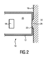
図1は、先行技術による皮膚パラメータ測定装置10の模式的な表現である。皮膚パラメータ測定装置10は、中空であり、皮膚パラメータの光学的測定を実行するように構成された光感知ユニット18を保持するための内部空洞20を定義する、筐体構造12を有する。光感知ユニット18は、皮膚の油っぽさ、皮膚のテクスチャ、及び毛穴を測定するように適合されたカメラプラットフォームを含んでいても良い。筐体構造12は、皮膚パラメータ測定装置10が身体部分14(例えば人)の皮膚表面16上で皮膚パラメータ測定を実行する位置に保持されたときに、筐体構造12の端部となる皮膚接触端24を有する。皮膚接触端24には、光皮膚パラメータ測定の間に光感知ユニット18から送信された及び/又は光感知ユニット18によって受信された光信号を透過させるための開口22が形成されている。従って、開口22は、測定窓として機能する。
FIG. 1 is a schematic representation of the skin
しかしながら、先行技術から知られている装置は、測定間の遅延がなくても、同一人物の皮膚表面上の同じスポットが繰り返し測定されると、測定結果のばらつきに悩まされる。このようなばらつきの主な原因の1つは、皮膚のドーミング26、即ち、皮膚パラメータ測定装置10の筐体構造12が皮膚パラメータ測定中に弾性皮膚に押し付けられたときに生じる皮膚表面のドーム状の変形である。筐体構造12は剛性のあるフレームを形成しており、このフレームが皮膚表面に押し付けられると、弾性皮膚が凸状になる。この皮膚ドーミング現象の効果を図2に例示する。
However, devices known from the prior art suffer from variations in measurement results when the same spot on the skin surface of the same person is repeatedly measured, even if there is no delay between measurements. One of the main causes of such variation is the dome shape of the skin surface that occurs when the
この皮膚ドーミング現象は、2つの態様で皮膚パラメータ測定結果の変動を増大させる。第1に、光感知ユニット(例えば照明光源とカメラ)によって捕捉される皮膚の視覚的特性を変化させる。皮膚パラメータ測定装置10の測定窓22を通して、照明源(例えば特別なLED)は、カメラが照明された皮膚表面を「見る」ように、照明されていなければ照らされていない(それ故に暗くなっている)皮膚表面を照明する。所望の角度で皮膚表面を照明するために使用される特別に配置されたLEDが、皮膚の曲率の違いのために光線の入射点で異なる反射を受ける可能性があるので、皮膚ドーミングは、カメラによって捕捉された視覚特性の変化をもたらす。第2に、皮膚ドームの高さがカメラの被写界深度(DOF)を超えると、皮膚がカメラによって合焦しなくなることがある。カメラの画像処理アルゴリズムを使用して捕捉された画像を処理する際に、多かれ少なかれぼやけた画像は、誤った測定結果をもたらす。
This skin doming phenomenon increases the variation in skin parameter measurement results in two aspects. First, it alters the visual properties of the skin captured by light sensing units (eg, illumination sources and cameras). Through the
皮膚ドーミングの効果は、弾性のような自然な皮膚の特性(例えば人の)、皮膚の下の支持組織(例えば筋肉、骨)の特性、皮膚パラメータ測定のために皮膚表面に押し付けられる剛体筐体フレームの設計及び/又は寸法、剛体筐体フレームが押し付けられる圧力レベル及び力を含む多くの要因によって、その範囲及び特性にさえ影響を受けることがある。 The effects of skin doming are natural skin properties such as elasticity (eg human), properties of supporting tissues under the skin (eg muscles, bones), rigid housing pressed against the skin surface for skin parameter measurements. Many factors, including the design and / or dimensions of the frame, the pressure level and force on which the rigid housing frame is pressed, can even affect its range and properties.
最初の2つの因子は、皮膚パラメータが測定されるべき所与の装置及び所与の人に対して一定であるが、圧力レベル及び力は、皮膚のドーミング、従って皮膚パラメータ測定結果の変動に最も大きな影響を及ぼす。皮膚パラメータ測定装置を皮膚に押し付ける力は、皮膚のドーミングのばらつきに大きく影響する。例えば、あるボランティア試験では、「額又は頬に優しく接触させる」ように求められたときに試験者のグループによって加えられる力の範囲は、ゼロから15Nまでの範囲であることが示されている。 The first two factors are constant for a given device and a given person for which skin parameters are to be measured, but pressure levels and forces are most dependent on skin doming, and thus fluctuations in skin parameter measurement results. It has a big impact. The force that presses the skin parameter measuring device against the skin greatly affects the variation in skin doming. For example, one volunteer study has shown that the range of force applied by a group of testers when asked to "gentle contact with the forehead or cheeks" ranges from zero to 15N.
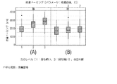
図3A及び3Bは、印加された力がどのようにしてより高いドーミングをもたらすかを見出すことを目的とした試験の結果を示す図である。試験で適用された力のレベルは、0.8Nから15Nまでの範囲であり、最も軽い力の場合はレベル1、中間の力の場合はレベル2、最も強い力の場合はレベル3の、3つのレベルにグループ化されている。図3Aは頬の皮膚、図3Bは額の皮膚の試験である。この試験では、直径15mmの固定窓枠(即ち、皮膚パラメータ測定のために皮膚表面に接触させた窓枠又は開口)に対して、印加された範囲の力に対して、皮膚のドーミングの高さが1mmから3mmの範囲であり、皮膚のドーミングのばらつきが2mm生じることが示されている。
3A and 3B are diagrams showing the results of tests aimed at finding out how the applied force results in higher doming. The force levels applied in the test range from 0.8N to 15N,
先行技術から知られている皮膚パラメータ測定装置は、皮膚表面上での光の乱れのない反射を必要とする特定の皮膚パラメータ(例えば、皮膚の油っぽさ)の解析を妨げる特定の欠点を有する。焦点外画像を防止するために当技術で提案されている解決策には、オートフォーカスカメラが含まれる。しかし、望ましくないコスト上昇の他に、このような解決策は、皮膚のドーミング効果が強く変化すると、出射光の反射も強く変化し、測定されるパラメータ(例えば、皮膚の油っぽさの値)の変化を増大させるという問題を解決することができない。 Skin parameter measuring devices known from the prior art have certain drawbacks that interfere with the analysis of certain skin parameters (eg, skin oiliness) that require undisturbed reflection of light on the skin surface. Have. Solutions proposed in the art to prevent out-of-focus images include autofocus cameras. However, in addition to the undesired cost increase, such a solution also strongly changes the reflection of emitted light as the skin doming effect changes strongly, and the parameters measured (eg, the value of skin oiliness). ) Cannot be solved.
当技術分野で知られている別の解決策は、皮膚ドーミングを平坦にするために、カメラの焦点面にガラス板又はメッシュを利用することを提案している。しかし、この手段は、皮膚表面の光反射に強く影響を与えるため、皮膚の油っぽさなどの特定の皮膚パラメータを測定するのには適していない。 Another solution known in the art proposes the use of a glass plate or mesh for the focal plane of the camera to flatten the skin doming. However, this method strongly affects the light reflection on the skin surface and is not suitable for measuring specific skin parameters such as oiliness of the skin.
皮膚表面の反射特性を変化させることなく、皮膚ドーミング効果の改善された制御を可能にする、皮膚パラメータを測定するための方法が望まれている。 There is a need for a method for measuring skin parameters that allows for improved control of the skin doming effect without altering the reflective properties of the skin surface.
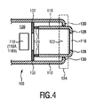
本分野から知られている皮膚パラメータ測定装置に関連する上述の問題を解決する本発明の一実施例による皮膚パラメータ測定装置100の模式的な表現を、図4に示す。皮膚パラメータ測定装置100は、光感知ユニット118を保持するための内部空洞120を定義する筐体構造112を有する。光感知ユニット118は、照明ユニット118a及び撮像ユニット118bを有する。光感知ユニット118は、皮膚の油っぽさ、テクスチャ、毛穴、色素沈着などの皮膚パラメータの光学的測定を実行するように構成されている。装置100が皮膚表面に接触しているとき、照明ユニット118aは、筐体構造112の皮膚接触端124の第1の開口122を介して光を放出することにより、皮膚表面を照明する。発せられた光は、照明された皮膚表面で反射され、撮像ユニット118bによって受光される。
FIG. 4 shows a schematic representation of the skin
皮膚パラメータ測定装置100は更に、弾性的な接続構成を介して筐体構造112に接続される可動部113を有する。可動部分113は、中空の内部空間と、皮膚接触端124に設けられた第2の開口116とを有する。弾性接続構成は、図4において、例示的には2つのばね126として示されている。ばね126の一方の側は、第2の開口116に対向する可動部分113の端部に固定され、ばね126の他方の側は、筐体構造112の内壁に突出する板状要素132に固定されている。
The skin
皮膚パラメータ測定装置100に外力が加えられていないとき(即ち皮膚表面に押し付けるため)、皮膚パラメータ測定装置100は、可動部分113が皮膚接触端124で筐体構造112を突出している非押圧状態にある。図4に見られるように、ばね126の弾性により、第2の開口116を定義する可動部113の前端部分は、筐体構造112の内部空洞120の外側にある。前端部分は、好適には、環状、例えば円形、長方形又は三角形の環状に形成された端部界面128を有する。第1の開口122を定義する筐体構造112の皮膚接触端部124の基底面130は、好適には環状形状で形成される。
When no external force is applied to the skin parameter measuring device 100 (that is, to press it against the skin surface), the skin
ばね126の弾性により、可動部分113は、皮膚表面に接触させて皮膚表面に更に押し付けると、筐体構造112の内部空洞120内に更に内向きに移動することができる。このようにして、可動部113は、「剛体フレーム」として機能する筐体構造112を取り囲む「浮動フレーム」として機能する。これは、図5A乃至Cで更に詳細に示される。
Due to the elasticity of the
図5A乃至Cは、本発明の別の実施例による皮膚パラメータ測定装置200の模式的な表現である。図5A乃至Cの皮膚パラメータ測定装置は、図4のものと類似している(同一の参照符号は、両方の図のセットにおいて同一の特徴を表す)。図5A乃至Cの実施例では、光感知ユニット118の照明ユニット118Aは、例示的には、カメラを構成する撮像ユニット118Bを取り囲むように配置された複数のLEDを有する。複数のLEDは、照明回路基板152、好適には印刷回路基板(PCB)上に配置される。更に好適には、可動部113に面する印刷基板の態様に偏光板ユニット135が設けられている。好適には、ばね126は、可動部113が外向きの収縮力を経験するように、プリテンションされた収縮ばねである。
5A to 5C are schematic representations of the skin
ばねの力によって可動部113が筐体構造112の外側に向かって更に移動するのを防止するために、可動部113は、筐体構造112に関して可動部113を内側に移動させるための外力が加えられていないときに、筐体構造112の皮膚接触端124の端部に押し付けられる当接要素134を有する。
In order to prevent the
筐体構造112内には、主回路基板188(例えばバッテリなどの電源に接続された主基板)、バッテリ184を受けるためのバッテリケース、及び/又は無線接続ポート186が配置されても良い。筐体構造112の皮膚接触端と反対側の端部には、装置の電源(例えばバッテリ184)を充電するための充電器ソケット182が設けられていても良い。記憶ユニット190のような他の機能ユニットが、筐体構造112に追加的に組み込まれても良い。
A main circuit board 188 (for example, a main board connected to a power source such as a battery), a battery case for receiving the
可動部113(浮動フレーム)が身体部分14の皮膚表面16にちょうど接触するように、ユーザが装置200を皮膚に乗せると、可動部113の端部界面に作用するわずかな力により、可動部113は筐体構造112に対して最小限に内向きに移動する。この適用状態は、図5Aに模式的に示されている。最小の力は、皮膚パラメータ測定装置200を保持しているユーザによって感じることができるので、ユーザには、押し続けるための手掛かりが有利に提供される。
When the user places the
装置200が皮膚表面16に対して更に押されると、可動部113は、筐体構造112(外部剛性フレーム)が皮膚とちょうど接触するまでの距離(例えば1乃至3mm)、筐体構造112に対して内向きに移動し続け、これにより、ユーザに更なる押圧を停止するためのフィードバックが与えられる。この適用状態は、図5Bに模式的に示されており、この状態は皮膚パラメータ測定が実行され得る状態(即ち「使用位置」)でもある。フィードバック機構は、ユーザが装置を皮膚表面に対して例外的に強く押す確率を低下させる。
When the
図5Cでは、皮膚パラメータ測定装置200は、ばね126が内部空洞120内でその最も内側の位置に到達するように最大限に圧縮されるように、可動部113が筐体構造112に対して内向きに押されている状態にある。皮膚パラメータ測定装置200のこの適用状態は、額や頬などの身体部分の皮膚表面に期待される最大のドーミング高さが、図5Bの状態に到達した後に可動部分113が内側に移動することを許容される最大距離よりも小さいので、通常、実際の使用においては到達しない。
In FIG. 5C, the skin
本発明は、ユーザの皮膚表面に作用する押圧力の制御に関して有利である。装置がユーザの皮膚に押し付けられる力は、装置に外部から加えられる押圧力がどのように作用するかによって特徴付けられるのではなく、可動部分113と筐体構造112との間の所定の相対位置(例えば図5Bに示すような)におけるばね126の圧縮力によって特徴付けられる。適用のためのばねのパラメータ(ばねの長さ及び剛性/ばね定数など)を適切に選択することにより、ばねの圧縮力は、変動がないか、又は最小となるように制御することができる。
The present invention is advantageous with respect to controlling the pressing force acting on the user's skin surface. The force with which the device is pressed against the user's skin is not characterized by how externally applied pressing force acts on the device, but rather at a predetermined relative position between the moving
それ故、このような浮動フレーム機構を持たない装置(例えば図1)を使用する場合と比較して、皮膚のドーミング高さが低減される。また、被写界深度が2.5mm以下のカメラを撮像部として使用した場合でも、ドーミング輪郭の低下により、異なるユーザに対しても合焦した皮膚画像を取得しやすくなる。更に、皮膚のドーミング効果の低減は、皮膚パラメータ測定のために異なるユーザが異なる皮膚への装置の押し方をした場合や、同じユーザが異なる測定機会に異なる押し方をした場合にも発生する、視覚的な皮膚特性のばらつきを低減することができる。このように本発明は、より少ないばらつきしか伴わない皮膚パラメータ測定結果を達成し、皮膚解析におけるより高い信頼性に導く。 Therefore, the doming height of the skin is reduced as compared to the case of using a device without such a floating frame mechanism (eg, FIG. 1). Further, even when a camera having a depth of field of 2.5 mm or less is used as an imaging unit, it becomes easy to acquire a focused skin image even for different users due to a decrease in the doming contour. In addition, the reduction in skin doming effect also occurs when different users press the device onto different skin to measure skin parameters, or when the same user presses differently on different measurement opportunities. Variations in visual skin characteristics can be reduced. Thus, the present invention achieves skin parameter measurement results with less variability, leading to higher reliability in skin analysis.
本発明の更なる利点は、皮膚パラメータ測定装置の動き(例えば、図5A及び図5Bに示された状態の間の筐体構造112の動き)が、本質的に皮膚表面に垂直な直線運動であることである。このことは、圧力の強さだけでなく、皮膚表面に対するその方向もより良好に制御可能であり、皮膚ドーミングの変動がより少ないことにつながることを意味する。
A further advantage of the present invention is that the movement of the skin parameter measuring device (eg, the movement of the
本発明の更なる利点は、測定を実行する前に、第1のフレーム(即ち浮動フレームとしての可動部)と第2のフレーム(即ち剛性フレームとしての筐体構造)とが皮膚表面と接触するという事実に関連している。これにより、ユーザの皮膚表面に対して装置が誤って角度をつけて配置される確率が減少するので、剛性のある測定窓枠を有する装置(例えば図1)と比較して、ユーザへのフィードバックが改善される。 A further advantage of the present invention is that the first frame (ie, the moving part as a floating frame) and the second frame (ie, the housing structure as a rigid frame) come into contact with the skin surface before performing the measurement. It is related to the fact. This reduces the probability that the device will be incorrectly angled with respect to the user's skin surface, thus reducing feedback to the user as compared to a device with a rigid measuring window frame (eg, FIG. 1). Is improved.
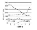
図6Aは、種々のばねのプリテンション及び装置設計を用いた皮膚ドーミング効果に関する試験の結果を表す図である。曲線A、B、C、Dは、それぞれ、1から6まで列挙された複数の装置(横軸)について、異なる構成のばねプリテンション(それぞれ0.8N又は1.5N)及び適用された皮膚表面(それぞれ頬又は額)の下での皮膚ドーミング高さの測定値(縦軸)を表している。装置設計パラメータ「浮動リム厚さ」、「浮動リム形状」及び「固定リム厚さ」は、図6Bに示されている。「浮動リム厚さ」及び「浮動リム形状」は、可動部の前端部断面の界面の幅とその幾何学的形状、即ち、環状形状が丸い(円形)か又は平坦(矩形)のいずれであるかを指す。「固定リム厚さ」とは、筐体構造の皮膚接触端部の基底面の幅を指す。図6Cは、例示的な設計を示しており、円形可動部109(浮動リム)の浮動リム厚さはh1で示され、筐体構造108(固定リム)の固定リム厚さはh2で示されている。 FIG. 6A is a diagram showing the results of tests on skin doming effect using various spring pretension and device designs. Curves A, B, C and D show different configurations of spring pretension (0.8N or 1.5N, respectively) and applied skin surface for multiple devices (horizontal axis) listed from 1 to 6, respectively. It represents the measured value (vertical axis) of the skin doming height under (cheek or forehead, respectively). The device design parameters "floating rim thickness", "floating rim shape" and "fixed rim thickness" are shown in FIG. 6B. "Floating rim thickness" and "floating rim shape" are the width of the interface of the front end cross section of the movable part and its geometric shape, that is, the annular shape is either round (circular) or flat (rectangular). Point to. "Fixed rim thickness" refers to the width of the basal plane of the skin contact end of the housing structure. FIG. 6C shows an exemplary design, where the floating rim thickness of the circular movable portion 109 (floating rim) is shown by h 1 and the fixed rim thickness of the housing structure 108 (fixed rim) is h 2 . It is shown.
該試験は、0.8Nのプリテンションの方が皮膚ドーム高さ、皮膚ドーム変動ともに良好な結果が得られることを示している。また、0.8Nのプリテンションのバネを用いて、皮膚パラメータ測定装置を皮膚表面に0.8N乃至15Nの力で押し付けた場合の皮膚ドーム高さは1.5mm乃至2.3mmの範囲内となり、皮膚ドーム変動は0.8Nとなった。先行技術の装置(図3A乃至3B)により提供される値(2mm)に比べて、この皮膚のドーミングのばらつきは著しく低減されている。 The test shows that 0.8 N pretension gives better results in both skin dome height and skin dome variation. In addition, the height of the skin dome is within the range of 1.5 mm to 2.3 mm when the skin parameter measuring device is pressed against the skin surface with a force of 0.8 N to 15 N using a 0.8 N pretension spring. , The skin dome fluctuation was 0.8N. This skin doming variability is significantly reduced compared to the values (2 mm) provided by the prior art devices (FIGS. 3A-3B).
図7A乃至Bは、可動部の測定窓枠(即ち測定窓を定義する第2の開口の枠)に関して、2つの設計を用いた比較測定の結果を表す図である。図7Aでは、円形の測定窓枠についての測定結果が示されており、ここでは、測定窓枠の直径が15mmであり、装置が額の皮膚表面に対して低圧で押し付けられている。また、図7Aの測定結果は、押圧力を制限するためにサスペンションを使用しない、即ち剛性のある測定窓枠を使用して、押圧力を制限することなく得られている。図7Bでは、長方形の測定窓枠を用いた場合の測定結果を示しており、測定窓枠の寸法は9.5mm×12.4mmであり、装置を額の皮膚表面に対して低い圧力(特に押圧力は1Nと2Nとの間)で押圧した場合の測定結果を示している。比較測定の結果、長方形の測定窓枠と比較して、円形の測定窓枠の方が、全方向の皮膚ドーミングをより均一化し、皮膚ドーミングに対する向き、即ち装置が皮膚表面に保持又は配置される向きの影響を、最小限に抑えられることがわかった。 7A to 7B are diagrams showing the results of comparative measurement using the two designs with respect to the measurement window frame of the movable portion (that is, the frame of the second opening that defines the measurement window). FIG. 7A shows the measurement results for a circular measuring window frame, where the diameter of the measuring window frame is 15 mm and the device is pressed against the skin surface of the forehead at low pressure. Further, the measurement result of FIG. 7A is obtained without using a suspension to limit the pressing force, that is, by using a rigid measurement window frame without limiting the pressing force. FIG. 7B shows the measurement results when a rectangular measurement window frame is used. The dimensions of the measurement window frame are 9.5 mm × 12.4 mm, and the device is subjected to low pressure (particularly) on the skin surface of the forehead. The pressing force is between 1N and 2N), and the measurement result is shown. As a result of the comparative measurement, the circular measurement window frame makes the skin doming in all directions more uniform as compared with the rectangular measurement window frame, and the orientation with respect to the skin doming, that is, the device is held or placed on the skin surface. It was found that the effect of orientation could be minimized.
遮られていない画像を得るためには、撮像ユニットとして使用されるカメラの矩形の視野(FOV)と同じ寸法又はそれよりも大きい寸法の(円形の)測定窓枠が好ましい。特に、カメラのFOVは、カメラの画角と焦点面までの距離によって定義される。従って、測定窓枠のサイズは、カメラのこれら2つのパラメータに基づいて選択されても良い。窓枠は、更に好適には、12mm×9mm以上の寸法を有する。 In order to obtain an unobstructed image, a (circular) measurement window frame having the same or larger dimensions as the rectangular field of view (FOV) of the camera used as the imaging unit is preferred. In particular, the FOV of a camera is defined by the angle of view of the camera and the distance to the focal plane. Therefore, the size of the measurement window frame may be selected based on these two parameters of the camera. The window frame more preferably has dimensions of 12 mm × 9 mm or more.
図8は、光感知ユニット118が可動部115内に固定的に配置されている点で、図5A乃至Cに示された実施例とは異なる、本発明の更なる実施例による皮膚パラメータ測定装置300の模式的な表現である。図8に例示的に示されているように、光感知ユニット118の照明ユニット118a及び撮像ユニット118b(例えばカメラ)は、皮膚端部界面及び第2の開口116を定義する前端部分とは反対側の端部である可動部分115の後端部分内に固定的に含まれている。有利にも、カメラの焦点距離は、外部の剛性フレーム(即ち筐体構造112)に対するばね式浮動フレーム(即ち可動部分115)の相対位置に関係なく、皮膚接触リングを形成する環状の皮膚端部界面に関して定義される。この状況で制御された皮膚ドーミングを保証するために、ばねは好適には、低い又はゼロの剛性(例えば0乃至0.5N/mm)及び/又は定義されたプリテンション(例えば0.8N)を持つ。
FIG. 8 is a skin parameter measuring device according to a further embodiment of the present invention, which is different from the embodiments shown in FIGS. 5A to 5C in that the
好適には、可動部115の後端部断面は、光感知ユニットを可動部115に確実に組み込むことができるように、後端部断面よりも大きな断面を有する。しかし、これは本発明を限定するものではなく、可動部には、変化する又は一定の直径を有する他の形態(例えば、円筒形など)が使用されても良い。
Preferably, the rear end cross section of the
以下では、上述した実施例(即ち図4、図5A乃至C、図8)によって含まれる特徴に加えて、第2の皮膚パラメータ、好適には皮膚インピーダンスを測定するための電気感知ユニットを更に含み、ここで、電気感知ユニットは、更に好適には、第2の開口を定義する可動部分の前端部分に配置される、皮膚パラメータ測定装置の更なる実施例が記載される。しかしながら、図1乃至8を参照して説明した特徴は、以下の更なる実施例に独立して適用可能であり、またその逆も同様である。 In the following, in addition to the features included by the embodiments described above (ie, FIGS. 4, 5A-5A, 8), a second skin parameter, preferably an electrical sensing unit for measuring skin impedance, is further included. Here, further embodiments of a skin parameter measuring device are described in which the electrical sensing unit is more preferably located at the front end portion of the movable portion that defines the second opening. However, the features described with reference to FIGS. 1-8 are independently applicable to the following further embodiments and vice versa.
生体インピーダンスは、互いに一定の距離を有する2つ以上の電気接点、又は電気接点のアレイを、皮膚表面に配置することによって測定することができる。電気信号、好適には高調波信号(例えば1つ以上の高調波を有する電気信号)が電極を介して送られ、そこで入力信号と受信信号との間の振幅及び位相の差が測定される。このことは、複数の皮膚特性、例えば、水分含有量(水和度)、皮脂含有量及び/又は塩分含有量(例えば割合)の指標となり得る皮膚インピーダンスを測定するために特に利用することができる。 Bioimpedance can be measured by placing two or more electrical contacts, or an array of electrical contacts, at a constant distance from each other on the surface of the skin. An electrical signal, preferably a harmonic signal (eg, an electrical signal having one or more harmonics), is sent through the electrodes where the amplitude and phase differences between the input and received signals are measured. This can be particularly utilized to measure skin impedance, which can be an indicator of multiple skin properties, such as water content (hydration), sebum content and / or salt content (eg percentage). ..
ある程度までは、電気接点(即ち電極)間の距離と信号周波数によって、インピーダンスが測定され得る皮膚の深さが決定される。またそれらは、測定された皮膚インピーダンスに対する、水分などの特定の皮膚パラメータの効果を決定する。 To some extent, the distance between electrical contacts (ie, electrodes) and the signal frequency determine the depth of skin at which impedance can be measured. They also determine the effect of certain skin parameters, such as water, on the measured skin impedance.
皮膚表面と電極との間の安定した接触は、皮膚インピーダンス測定において信頼できる結果を得るために有利である。皮膚は複数の柔軟なテクスチャを持ち得るので、接触圧力の変動は、皮膚表面と皮膚パラメータ測定装置との間の接触界面の形状及び大きさの変動につながる。このことは、測定結果のばらつきにつながる。接触圧のばらつきの原因としては、皮膚パラメータ測定装置を皮膚表面に押し付ける際の操作者の力だけでなく、皮膚に押し付ける際の皮膚表面に対する皮膚パラメータ測定装置の保持角度などが挙げられる。皮膚表面に対して垂直な角度から逸脱した角度は、圧力分布に違いを生じさせ、その結果、測定された皮膚インピーダンスの変動を引き起こす可能性がある。最後に、これらの影響は、接触面積(即ち電気接点によって接触される皮膚表面の面積)が小さい電気接点の場合には、接触面積が大きい電気接点の場合よりも大きくなる。 Stable contact between the skin surface and the electrodes is advantageous for obtaining reliable results in skin impedance measurements. Since the skin can have multiple soft textures, fluctuations in contact pressure lead to fluctuations in the shape and size of the contact interface between the skin surface and the skin parameter measuring device. This leads to variations in measurement results. The cause of the variation in the contact pressure includes not only the force of the operator when pressing the skin parameter measuring device against the skin surface, but also the holding angle of the skin parameter measuring device with respect to the skin surface when pressing against the skin. Angles that deviate from an angle perpendicular to the skin surface can make a difference in the pressure distribution, resulting in fluctuations in the measured skin impedance. Finally, these effects are greater for electrical contacts with a small contact area (ie, the area of the skin surface contacted by the electrical contacts) than for electrical contacts with a large contact area.
図9は、本発明の一実施例による皮膚パラメータ測定装置400を示す。皮膚パラメータ測定装置400は、図4に示された実施例と本質的に同じ特徴を有し、更に好適には、可動部117に形成された2つの電気接点136を有する電気感知ユニットを有する。例示的には、電気接点136は、可動部分117の皮膚端界面から内向きに延びるように可動部分117の前端部分に設けられる。代替的に又は追加的に、電気接点136は、可動部分117の全長に亘って、又は全長の一部分に亘って、可動部分117に沿って内向きに延在しても良い。
FIG. 9 shows a skin
従って、本発明は、光学的測定装置と電気的測定装置の組み合わせを提供するので、皮膚パラメータ測定装置の適用可能性は、当技術分野で知られている装置と比較してより大きくなる。 Therefore, since the present invention provides a combination of an optical measuring device and an electrical measuring device, the applicability of the skin parameter measuring device is greater than that of a device known in the art.
図9では、2つの電気接点が例示的に示されている。しかしながら、電気接点の数は2個より多くても良い。上述したように、可動部117の前端部分は、好適には円形、長方形、又は三角形の環状に形成されていても良い。更に好適には、電気感知ユニット136は、可動部117の前端部分の環状形状内に互いに固定的に離間して分布する、複数の電気接点を有する。
In FIG. 9, two electrical contacts are shown exemplary. However, the number of electrical contacts may be greater than two. As described above, the front end portion of the
このようにして、ユーザによる皮膚パラメータ測定装置の取り扱い中の角度変動が最小化される。好適には、環状形状の「直径」(即ち環状形状の対向する2つの側面間の最大距離、平均距離又は最小距離、特に環状形状の外周又は内周での距離)は、装置が皮膚上に配置されたときに、正しい配置の適切なフィードバックをユーザに確実に与えるために、十分に大きい。例えば、該直径は、10mm乃至50mm、より好適には15mm乃至20mmの範囲であっても良い。 In this way, the angle variation during the handling of the skin parameter measuring device by the user is minimized. Preferably, the "diameter" of the annular shape (ie, the maximum, average or minimum distance between two opposing sides of the annular shape, especially the distance on the outer or inner circumference of the annular shape) is such that the device is placed on the skin. Large enough to ensure that the user is given the proper feedback on the correct placement when placed. For example, the diameter may be in the range of 10 mm to 50 mm, more preferably 15 mm to 20 mm.
図10A乃至Cは、可動部分の環状の環状に配された複数の例示的な電気接点を示す。図10Aでは、2つの電気接点138、140が、可動部分の前端部分の基底面146内に設けられており、電気接点138、140は、それぞれ複数の歯部を構成している。図10Bでは、電気接点142は、基底面146上に円形に配置されており、各電気接点142は、台形の形状を有している。図10Cでは、円形の電気接点144は、基底面146上に円形に分布している。
10A-C show a plurality of exemplary electrical contacts arranged in an annular ring of moving parts. In FIG. 10A, two
図10D乃至Eは、第2の開口116を定義する可動部分の基底面146のそれぞれの例示的な形態を示す。図10Dでは、基底面146は、その両外周に矩形の環状の形状を有し、図10Eでは、基底面146は、その外周に三角形の環状の形状を有し、内周に円形の環状の形状を有する。
10D-E show exemplary forms of the
それに加えて、弾性接続構成(図9では2つのばね126として例示的に示されている)により、浮動フレーム(即ち可動部117)が剛性フレーム(即ち筐体構造112)内で前後に移動可能であることが可能になる。好適には、筐体構造の皮膚接触端部は、皮膚表面と接触するための環状の基底面を有し、環状の基底面は、2mm以上の環幅を有する。これにより、測定ツールが皮膚表面に押し付けられたときに、浮動フレームが基底面と完全に水平になった時に、皮膚接触のための安定したベースが確保される。
In addition, the elastic connection configuration (shown exemplary as two
図11は、本発明の更なる実施例による皮膚パラメータ測定装置500を示す。ここでは、可動部150は、その前端部断面において環状の環状形状を有している。2つの電気接点148a、bは、可動部分150の一部を形成するように、環状形状内に配置されている。特に、電気接点148a、bは、それぞれ、可動部分150の2つの部分によって分離された弧状形状を持つ。筐体構造112は、可動部分150を取り囲むように設けられている。照明回路基板152、好適には印刷回路基板(PCB)が、筐体構造112の内部空洞内に固定的に配置されており、ここで、複数のLED154(照明ユニット)が、照明回路基板152の中央孔170の周りに周方向に配置されている。カメラ156(撮像ユニット)は、筐体構造112の内部空洞内において、照明回路基板152に対して内側に配置されている。LED154から発せられた光は、装置500を皮膚表面に近接又は接触させると、可動部150の第2開口116を介して皮膚表面に到達する。次いで、皮膚表面から反射された光が、照明回路基板152の中央孔170を介してカメラ156に向かう。
FIG. 11 shows a skin
図12A乃至Bでは、図11の装置500が側面図で示されている。図12Aでは、装置500は非押圧状態にあり、図12Bでは、装置500は皮膚表面(図示せず)に接触させられ、可動部分150は皮膚のドーミング(図示せず)により内側に移動する。 可動部分150(浮動フレーム)は好適には、プラスチック製の第1の部分と、電気接点148a、bを形成する第2の部分とから構成される。第1の部分は、ばね160を担持する2つのガイド脚162を有し、そこに形成された2つのガイド孔を介して照明回路基板152を通るように延びている。これにより、使用中の装置500のバランスのとれた直線運動が保証される。ばね160の自然な長さは例示的には18.7mmであるが、デフォルトの非押圧状態では7.4mm収縮しており、0.55Nのプリテンションを与えている。
In FIGS. 12A to 12B, the
通常、ユーザが皮膚解析器を頭に押し付けると、可動部150(浮動フレーム)の皮膚端界面164が皮膚表面に接触する(図12A)。この位置から、皮膚表面に押し付けられた浮動フレームは、筐体構造(外側の静的フレーム又は剛性フレーム)の基底面166がユーザの皮膚表面に接触するまで、更に2.5mm(図12Aにおいてd1として示される)の距離だけ内側に移動することができる。額や頬のような身体部分の皮膚表面の凸曲率を考えると、この最終位置における筐体構造112の基底面166からの可動部150の皮膚端界面164の距離(図12Bにおいてd2として示される)は、1mmである。この時点で、圧縮によるばね力の計算値は0.81Nである。+0.5mmと−0.5mmとの間の圧縮されたばねの長さにおける小さな予想される変動(符号+及び−は、それぞればねの長さの増加及び減少を示す)については、ばね力の変動は、+0.02Nと−0.02Nとの間の範囲内(符号+及び−は、それぞれ長さが減少及び増加したときのばね力の方向を示す)となる。従って、ばね力の変動は有利には低いレベルにある。
Normally, when the user presses the skin analyzer against the head, the
本実施例で使用されるカメラ156は、+/−1.5の被写界深度を持つ。更に、カメラ156は、浮動フレームの皮膚端界面164の理想的な最終位置から0.5mm内側にある焦点面を持つ。このことは、ばね162のために浮動フレームによって皮膚表面に及ぼされる圧力のために生じる皮膚ドーミングの平均レベルを考慮するためである。焦点面のこの内向きバイアスは、自然な曲率(額及び頬の)及び圧力の影響の両方に起因して、皮膚が一方向にのみドームを形成するという事実に起因している。
The
更なる実施例では、浮動フレームは、ガイド脚以外の手段を用いて支持されても良く、ばねは、位置決めのための他の手段を用いてガイドされても良い。ガイド脚が利用される場合、任意の数の脚又は全ての脚が、装置の皮膚接触端から内部空洞へ、更には皮膚接触端と反対側の装置の端部まで、配線を担持するための追加の機能的な通路(例えばトンネル)を提供しても良い。更に、任意の数の脚又は全ての脚が、バランスのとれたばね付勢された浮動システムを生成するために、追加のガイドレール又は他の機構を備えたばねを支持するために使用されても良い。また、身体の異なる部分が測定される場合、及び/又は画像のフレーミングの全体的な寸法が異なる場合、異なるユーザ及び/又は異なる用途に適合するように力が調整されても良い。 In a further embodiment, the floating frame may be supported by means other than the guide legs and the springs may be guided by other means for positioning. When guide legs are used, any number of legs or all legs are for carrying the wiring from the skin contact end of the device to the internal cavity and further to the end of the device opposite the skin contact end. Additional functional passages (eg, tunnels) may be provided. In addition, any number of legs or all legs may be used to support springs with additional guide rails or other mechanisms to produce a balanced spring-urged floating system. .. Also, if different parts of the body are measured and / or if the overall dimensions of the framing of the image are different, the force may be adjusted to suit different users and / or different applications.
外部剛性フレームと皮膚表面との間の接触を可能にするために、浮動フレームが十分に内側に(例えば所定の距離だけ)移動されたときにのみ画像が撮影され、斯くして、皮膚がカメラの焦点領域内にあることを確実にするために、好適には、外部剛性フレームに対する浮動フレームの相対位置を検出するための第1の検出ユニットが追加されている。当該検出は、好適には、カメラによる撮像のためのトリガとして使用することができる。 The image is taken only when the floating frame has been moved sufficiently inward (eg, by a given distance) to allow contact between the external rigid frame and the skin surface, thus the skin is camerad. To ensure that it is within the focal region of, a first detection unit is preferably added to detect the relative position of the floating frame with respect to the external rigid frame. The detection can preferably be used as a trigger for imaging by a camera.
本発明は、電気接点と皮膚との間の適切な接触が検出されたときに、皮膚インピーダンス測定が正しく行われたことを信号で知らせるように構成されても良い。例えばこのことは、下限閾値に対して装置のインピーダンス測定値をチェックするための第2の検出ユニットによって達成されても良い。皮膚は通常、特定のインピーダンス範囲を持つ。適用される電気信号の周波数が32kHzの場合、比インピーダンス範囲は、平均的な人の場合、4乃至45KΩである。ユーザインタフェース(UI)を有するスタンドアロン型装置の場合、「測定」ボタンを押した後に予め設定された時間が経過した場合、装置はUIを介して、予め設定された時間内に下限閾値を超える値が検出された場合には正しい測定が取得されたことを示し、その時間内に下限閾値を超える値が検出されなかった場合にはその逆を示しても良い。「接続された装置」の場合、ユーザは、例えばスマートフォンアプリを介して測定を開始しても良い。測定開始から測定された予め設定された時間持続時間の後に、下限閾値を超える値が取得されなかった場合、ユーザは、測定が不正確であり、やり直すべきであるというメッセージを(例えば、アプリを介して)受け取っても良い。 The present invention may be configured to signal that the skin impedance measurement has been performed correctly when an appropriate contact between the electrical contact and the skin is detected. For example, this may be achieved by a second detection unit for checking the impedance measurements of the device against the lower threshold. The skin usually has a specific impedance range. When the frequency of the applied electrical signal is 32 kHz, the specific impedance range is 4 to 45 KΩ for the average person. In the case of a stand-alone device with a user interface (UI), if a preset time elapses after pressing the "Measure" button, the device will exceed the lower limit threshold within a preset time via the UI. If is detected, it may indicate that the correct measurement has been obtained, and if a value exceeding the lower limit threshold is not detected within that time, the opposite may be indicated. In the case of a "connected device", the user may start the measurement, for example, via a smartphone app. If no value above the lower threshold is obtained after a preset time duration measured from the start of the measurement, the user will be informed that the measurement is inaccurate and should be redone (eg, the app). You may receive it (via).
インピーダンス測定中に正しい圧力レベルを確保するために、固定された外枠に対する電極の相対位置を検出するための第3の検出ユニットを追加しても良い。インピーダンス測定は、固定外枠の長手方向に沿った所定の相対位置が検出された場合にのみ実行される。この検出は、ばねが十分に圧縮された瞬間にインピーダンス測定値を取得するためのトリガとして利用することができる。 A third detection unit may be added to detect the relative position of the electrodes with respect to the fixed outer frame to ensure the correct pressure level during the impedance measurement. Impedance measurement is performed only when a predetermined relative position along the longitudinal direction of the fixed outer frame is detected. This detection can be used as a trigger to obtain an impedance measurement at the moment the spring is fully compressed.
図13は、本発明の更なる実施例による皮膚パラメータ測定装置600の模式的な表現である。この実施例では、皮膚パラメータ測定装置600の筐体構造112は、取り外し可能な部分172を構成する。好適には、装置600を電源オン及び/又はオフにするためのボタン173が、筐体構造112の側面に配置されている。
FIG. 13 is a schematic representation of the skin
図14A乃至Bは、それぞれ本発明の可動部の模式的な表現を示す。図14A乃至Bに示す可動部分174、176は、それぞれが弧状形状を有し、可動部分174、176のプラスチック部分によって分離された2つの電気接点148a、bを有する。電気接点148a、bは、可動部分174、176のプラスチック部分によって支持されている。更に、2つの実施例の可動部分174、176には、それぞれ、例えば、照明回路基板及び/又は装置の主電源回路基板(主PCB)と接続するためのプラグ178又は配線180が設けられている。可動部分174、176は、皮膚パラメータ測定装置を形成するために、筐体構造に(例えばクリップのような着脱可能な機械的接続のための手段を介して)取り付けられても良い。
14A to 14B show schematic representations of the moving parts of the present invention, respectively. The
十分な直径を有する環状電極を、十分な、好適には平坦な基底面を有する剛性フレーム内にバネで懸架させた状態で組み合わせることは、皮膚表面に安定して配置されたときに、上述したようにユーザにフィードバックを提供する装置を実現するのに有利である。更に、安定して配置された位置では、インピーダンス測定における圧力に起因する変動が許容できるほど低いレベルに低減され、その結果、十分に低い測定変動が得られる。 The combination of annular electrodes of sufficient diameter, spring-suspended within a rigid frame with a sufficient, preferably flat basal plane, is described above when stably placed on the skin surface. It is advantageous to realize a device that provides feedback to the user. In addition, at stable locations, pressure-induced fluctuations in impedance measurements are reduced to acceptablely low levels, resulting in sufficiently low measurement fluctuations.
ばね懸架された環状電極と光感知機能の組み合わせは、電気的皮膚パラメータ測定(例えば、皮膚インピーダンス測定)のための接触圧力と光的皮膚パラメータ測定(例えば皮膚撮像)のための皮膚ドーミングの両方がよりよく制御される統合的な方法を実現する。この組み合わせ方法の更なる利点は、最適な人間工学的特性を有する、よりコンパクトでコスト効率の良い設計である。 The combination of spring-suspended annular electrodes and light sensing function provides both contact pressure for electrical skin parameter measurements (eg, skin impedance measurements) and skin doming for optical skin parameter measurements (eg skin imaging). Achieve a better controlled and integrated method. A further advantage of this combination method is a more compact and cost effective design with optimal ergonomic properties.
図15は、皮膚パラメータ測定装置701と、皮膚パラメータ測定装置701によって提供される皮膚パラメータ測定結果を解析するための解析ユニット702と、解析ユニット702の解析結果に基づいてシステムの設定を適応させるための適応ユニット703と、を有する好適な皮膚ケアシステム700を示す。皮膚パラメータ測定装置701は、上述した本発明のどのような実施例であっても良い。
FIG. 15 shows the skin
本発明は図面及び以上の記述において説明され記載されたが、斯かる説明及び記載は説明するもの又は例示的なものであって、限定するものではないとみなされるべきである。本発明は開示された実施例に限定されるものではない。図面、説明及び添付される請求項を読むことにより、請求される本発明を実施化する当業者によって、開示された実施例に対する他の変形が理解され実行され得る。 Although the present invention has been described and described in the drawings and the above description, such description and description should be deemed to be explanatory or exemplary and not limiting. The present invention is not limited to the disclosed examples. By reading the drawings, description and the accompanying claims, other modifications to the disclosed embodiments may be understood and implemented by those skilled in the art who practice the claimed invention.
請求項において、「有する(comprising)」なる語は他の要素又はステップを除外するものではなく、「1つの(a又はan)」なる不定冠詞は複数を除外するものではない。単一のプロセッサ又はその他のユニットが、請求項に列記された幾つかのアイテムの機能を実行しても良い。特定の手段が相互に異なる従属請求項に列挙されているという単なる事実は、これら手段の組み合わせが有利に利用されることができないことを示すものではない。 In the claims, the word "comprising" does not exclude other elements or steps, and the indefinite article "one (a or an)" does not exclude more than one. A single processor or other unit may perform the functions of some of the items listed in the claims. The mere fact that certain means are listed in different dependent claims does not indicate that the combination of these means cannot be used to their advantage.
コンピュータプログラムは、他のハードウェアと共に又は他のハードウェアの一部として供給される光記憶媒体又は固体媒体のような適切な媒体上で保存/配布されても良いが、インターネット又はその他の有線若しくは無線通信システムを介してのような、他の形態で配布されても良い。 Computer programs may be stored / distributed on suitable media such as optical storage media or solid-state media supplied with or as part of other hardware, but on the Internet or other wired or other wired or It may be distributed in other forms, such as via a wireless communication system.
請求項におけるいずれの参照記号も、請求の範囲を限定するものとして解釈されるべきではない。 None of the reference symbols in the claims should be construed as limiting the scope of the claims.
Claims (14)
内部空洞と、前記内部空洞の皮膚接触端における第1の開口と、を定義する筐体構造と、
弾性接続構成を介して前記筐体構造に接続された可動部であって、前記可動部は、前記筐体内に少なくとも部分的に前記可動部がとどまるよう前記筐体構造に対して移動可能であり、前記可動部に外力がかけられていないときには前記第1の開口から突出するように構成され、前端部分において第2の開口を更に有する、可動部と、
第1の皮膚パラメータの測定を実行するための光感知ユニットであって、前記光感知ユニットは、前記筐体構造の前記内部空洞内に備えられ、前記可動部の前記第2の開口を通して光を発することにより皮膚表面を照明するための照明ユニットと、前記照明された皮膚表面により反射された光を受光するための撮像ユニットと、を有する、光感知ユニットと、
第2の皮膚パラメータを測定するための電気感知ユニットであって、前記第2の開口を定義する前記可動部の前端部分に配置された、電気感知ユニットと、
を有する装置。 A device for measuring at least one skin parameter,
A housing structure that defines an internal cavity and a first opening at the skin contact end of the internal cavity.
A movable portion connected to the housing structure via an elastic connection configuration, and the movable portion is movable with respect to the housing structure so that the movable portion stays in the housing at least partially. A movable portion, which is configured to protrude from the first opening when no external force is applied to the movable portion and further has a second opening at the front end portion.
A light sensing unit for performing the measurement of the first skin parameter, the light sensing unit is provided in the internal cavity of the housing structure and allows light to pass through the second opening of the movable portion. A light sensing unit having a lighting unit for illuminating the skin surface by emitting light and an imaging unit for receiving the light reflected by the illuminated skin surface.
An electrical sensing unit for measuring a second skin parameter, the electrical sensing unit located at the front end portion of the movable portion defining the second opening.
A device having.
前記装置により提供される測定結果を解析するための解析ユニットと、
を有する皮膚ケアシステム。 The device according to claim 1 for measuring skin parameters, and
An analysis unit for analyzing the measurement results provided by the device, and
Skin care system with.
前記装置が皮膚表面に接触しているときに、前記光感知ユニットを用いて、第1の皮膚パラメータの測定を実行するステップと、
前記照明ユニットを用いて、前記可動部の第2の開口を通して光を発することにより、前記皮膚表面を照明するステップと、
前記撮像ユニットを用いて、前記照明された皮膚表面により反射された光を受光するステップと、
前記電気感知ユニットを用いて、前記装置が皮膚表面に接触しているときに、第2の皮膚パラメータの測定を実行するステップと、
を有する方法。 A method for measuring skin parameters using the apparatus according to claim 1.
A step of performing a first skin parameter measurement using the light sensing unit when the device is in contact with the skin surface.
A step of illuminating the skin surface by emitting light through the second opening of the movable portion using the illumination unit.
The step of receiving the light reflected by the illuminated skin surface using the imaging unit, and
A step of using the electrical sensing unit to perform a second skin parameter measurement when the device is in contact with the skin surface.
Method to have.
Applications Claiming Priority (3)
| Application Number | Priority Date | Filing Date | Title |
|---|---|---|---|
| EP18160454.7A EP3536223A1 (en) | 2018-03-07 | 2018-03-07 | Device, system and method for measurement of a skin parameter |
| EP18160454.7 | 2018-03-07 | ||
| PCT/EP2019/054885 WO2019170497A1 (en) | 2018-03-07 | 2019-02-27 | Device, system and method for measurement of a skin parameter |
Publications (2)
| Publication Number | Publication Date |
|---|---|
| JP2021509070A JP2021509070A (en) | 2021-03-18 |
| JP6887573B2 true JP6887573B2 (en) | 2021-06-16 |
Family
ID=61691207
Family Applications (1)
| Application Number | Title | Priority Date | Filing Date |
|---|---|---|---|
| JP2020544894A Active JP6887573B2 (en) | 2018-03-07 | 2019-02-27 | Devices, systems, methods and computer programs for measuring skin parameters |
Country Status (9)
| Country | Link |
|---|---|
| US (1) | US20200390362A1 (en) |
| EP (2) | EP3536223A1 (en) |
| JP (1) | JP6887573B2 (en) |
| CN (2) | CN110236486A (en) |
| BR (1) | BR112020018028A2 (en) |
| ES (1) | ES2905476T3 (en) |
| MX (1) | MX2020009195A (en) |
| PL (1) | PL3761850T3 (en) |
| WO (1) | WO2019170497A1 (en) |
Families Citing this family (11)
| Publication number | Priority date | Publication date | Assignee | Title |
|---|---|---|---|---|
| KR101856909B1 (en) * | 2017-10-26 | 2018-05-10 | 박창식 | Apparatus for Measuring Skin Condition with Multiple Lights |
| EP3569139A1 (en) * | 2018-05-17 | 2019-11-20 | Polar Electro Oy | Floating cardiac activity sensor for a sports equipment handle |
| EP3801243B1 (en) * | 2018-05-24 | 2022-04-20 | Scibase Ab | Impedance measurement device |
| USD935030S1 (en) * | 2019-04-15 | 2021-11-02 | Koninklijke Philips N.V. | Skin measurement device |
| CN112539868B (en) * | 2019-09-23 | 2022-03-11 | 北京远见医疗技术发展有限责任公司 | Method and equipment for detecting internal pressure and surface tangent tension of spherical capsule through surface |
| USD942020S1 (en) * | 2019-10-15 | 2022-01-25 | Koninklijke Philips N.V. | Skin measurement device |
| CN111110234B (en) * | 2019-12-11 | 2021-12-14 | 广州医科大学 | Skin jaundice detector and detection method |
| CN112773335B (en) * | 2021-02-07 | 2021-12-28 | 苏州大学 | Sensor, imaging system and imaging method applied to optical coherent elastography |
| CN113143206B (en) * | 2021-02-23 | 2023-08-01 | 添可智能科技有限公司 | Nursing equipment, elasticity detection equipment and detection method |
| CN115414004A (en) * | 2022-08-19 | 2022-12-02 | 厦门松霖科技股份有限公司 | Skin measuring instrument with moisture detection function, skin measuring system and skin measuring method |
| WO2024137956A2 (en) * | 2022-12-21 | 2024-06-27 | KATO Medical, Inc. | Systems and methods for a spinal anatomy registration framework |
Family Cites Families (11)
| Publication number | Priority date | Publication date | Assignee | Title |
|---|---|---|---|---|
| US6122544A (en) * | 1998-05-01 | 2000-09-19 | Organ; Leslie William | Electrical impedance method and apparatus for detecting and diagnosing diseases |
| JP3303831B2 (en) * | 1999-03-31 | 2002-07-22 | ミノルタ株式会社 | Percutaneous bilirubin concentration measurement device and measurement data inspection plate used for this measurement device |
| US6591122B2 (en) * | 2001-03-16 | 2003-07-08 | Nellcor Puritan Bennett Incorporated | Device and method for monitoring body fluid and electrolyte disorders |
| JP3954533B2 (en) * | 2003-06-17 | 2007-08-08 | 株式会社モリテックス | Skin observation device |
| WO2007026339A2 (en) * | 2005-09-02 | 2007-03-08 | The Procter & Gamble Company | Method and device for indicating moisture content of skin |
| KR101213157B1 (en) * | 2006-06-09 | 2012-12-17 | 삼성전자주식회사 | Sensor for measuring skin impedence |
| IT1399338B1 (en) * | 2010-03-29 | 2013-04-16 | Fond Istituto Italiano Di Tecnologia | METHOD AND DEVICE FOR MEASURING THE DEGREE OF HUMAN SKIN HUMIDITY. |
| EP2884882A1 (en) * | 2012-08-20 | 2015-06-24 | Symae Technologies Holding B.V. | Improved skin and scalp diagnosis device and method |
| JP6049518B2 (en) * | 2013-03-27 | 2016-12-21 | オリンパス株式会社 | Image processing apparatus, endoscope apparatus, program, and operation method of image processing apparatus |
| WO2015085240A1 (en) * | 2013-12-05 | 2015-06-11 | Veriskin Llc | Skin perfusion monitoring device |
| EP3496593B1 (en) * | 2016-08-09 | 2024-05-15 | Koninklijke Philips N.V. | Device and method for measuring skin elasticity |
-
2018
- 2018-03-07 EP EP18160454.7A patent/EP3536223A1/en not_active Withdrawn
-
2019
- 2019-02-27 MX MX2020009195A patent/MX2020009195A/en unknown
- 2019-02-27 ES ES19708468T patent/ES2905476T3/en active Active
- 2019-02-27 WO PCT/EP2019/054885 patent/WO2019170497A1/en unknown
- 2019-02-27 EP EP19708468.4A patent/EP3761850B1/en active Active
- 2019-02-27 PL PL19708468T patent/PL3761850T3/en unknown
- 2019-02-27 JP JP2020544894A patent/JP6887573B2/en active Active
- 2019-02-27 US US16/977,620 patent/US20200390362A1/en active Pending
- 2019-02-27 BR BR112020018028-9A patent/BR112020018028A2/en not_active Application Discontinuation
- 2019-03-06 CN CN201910169092.9A patent/CN110236486A/en active Pending
- 2019-03-06 CN CN201920282992.XU patent/CN211409018U/en active Active
Also Published As
| Publication number | Publication date |
|---|---|
| ES2905476T3 (en) | 2022-04-08 |
| RU2020133062A3 (en) | 2022-04-07 |
| CN211409018U (en) | 2020-09-04 |
| EP3761850B1 (en) | 2021-11-24 |
| EP3761850A1 (en) | 2021-01-13 |
| WO2019170497A1 (en) | 2019-09-12 |
| US20200390362A1 (en) | 2020-12-17 |
| EP3536223A1 (en) | 2019-09-11 |
| JP2021509070A (en) | 2021-03-18 |
| MX2020009195A (en) | 2020-10-08 |
| CN110236486A (en) | 2019-09-17 |
| PL3761850T3 (en) | 2022-04-25 |
| BR112020018028A2 (en) | 2020-12-22 |
| RU2020133062A (en) | 2022-04-07 |
Similar Documents
| Publication | Publication Date | Title |
|---|---|---|
| JP6887573B2 (en) | Devices, systems, methods and computer programs for measuring skin parameters | |
| CN109984735B (en) | Biological signal measuring device and method of operating the same | |
| JP6363158B2 (en) | Stethoscope | |
| KR102464916B1 (en) | Ring type wearable device | |
| JP5162602B2 (en) | Puncture device with needle puncture pain reduction mechanism and needle puncture pain reduction device | |
| KR20200121797A (en) | Eyewear that detects biometrics | |
| RU2760377C2 (en) | Apparatus and method for measuring the elasticity of skin | |
| CN111148977A (en) | Moving platform compression-induced imaging for sub-surface and surface object characterization | |
| JP6627374B2 (en) | Electronics | |
| CN113439913B (en) | Wearable equipment | |
| RU2788117C2 (en) | Device, system, and method for measurement of skin parameters | |
| JP5274829B2 (en) | Non-invasive living body measurement device | |
| CN113143206B (en) | Nursing equipment, elasticity detection equipment and detection method | |
| FI114198B (en) | Method and system for imaging the organ | |
| WO2021117707A1 (en) | Electrocardiographic waveform measurement device, information management system, electrocardiographic waveform measurement device control method, and program | |
| JP2010167092A (en) | Ophthalmic fatigue measuring device | |
| JP2006296808A (en) | Blood pressure measuring apparatus | |
| CN110543829A (en) | Object recognition system | |
| CN113144418B (en) | Electrode assembly and nursing equipment | |
| CN113144420B (en) | Nursing equipment and detection method | |
| CN113144421B (en) | Nursing equipment and control method | |
| JP2011200308A (en) | Beautification apparatus | |
| KR20180027299A (en) | Health band terminal | |
| JP6862739B2 (en) | Biographer and multifunctional clock | |
| CN116897067A (en) | Nursing equipment and rotating assembly |
Legal Events
| Date | Code | Title | Description |
|---|---|---|---|
| A621 | Written request for application examination |
Free format text: JAPANESE INTERMEDIATE CODE: A621 Effective date: 20200826 |
|
| A871 | Explanation of circumstances concerning accelerated examination |
Free format text: JAPANESE INTERMEDIATE CODE: A871 Effective date: 20200826 |
|
| A975 | Report on accelerated examination |
Free format text: JAPANESE INTERMEDIATE CODE: A971005 Effective date: 20201218 |
|
| A131 | Notification of reasons for refusal |
Free format text: JAPANESE INTERMEDIATE CODE: A131 Effective date: 20210105 |
|
| A521 | Request for written amendment filed |
Free format text: JAPANESE INTERMEDIATE CODE: A523 Effective date: 20210305 |
|
| TRDD | Decision of grant or rejection written | ||
| A01 | Written decision to grant a patent or to grant a registration (utility model) |
Free format text: JAPANESE INTERMEDIATE CODE: A01 Effective date: 20210511 |
|
| A61 | First payment of annual fees (during grant procedure) |
Free format text: JAPANESE INTERMEDIATE CODE: A61 Effective date: 20210518 |
|
| R150 | Certificate of patent or registration of utility model |
Ref document number: 6887573 Country of ref document: JP Free format text: JAPANESE INTERMEDIATE CODE: R150 |
|
| R250 | Receipt of annual fees |
Free format text: JAPANESE INTERMEDIATE CODE: R250 |