JP6887222B2 - Polarizing plate set - Google Patents
Polarizing plate set Download PDFInfo
- Publication number
- JP6887222B2 JP6887222B2 JP2016122961A JP2016122961A JP6887222B2 JP 6887222 B2 JP6887222 B2 JP 6887222B2 JP 2016122961 A JP2016122961 A JP 2016122961A JP 2016122961 A JP2016122961 A JP 2016122961A JP 6887222 B2 JP6887222 B2 JP 6887222B2
- Authority
- JP
- Japan
- Prior art keywords
- polarizing plate
- adhesive layer
- sensitive adhesive
- pressure
- polarizer
- Prior art date
- Legal status (The legal status is an assumption and is not a legal conclusion. Google has not performed a legal analysis and makes no representation as to the accuracy of the status listed.)
- Active
Links
Images


Classifications
-
- G—PHYSICS
- G02—OPTICS
- G02B—OPTICAL ELEMENTS, SYSTEMS OR APPARATUS
- G02B5/00—Optical elements other than lenses
- G02B5/30—Polarising elements
-
- G—PHYSICS
- G02—OPTICS
- G02F—OPTICAL DEVICES OR ARRANGEMENTS FOR THE CONTROL OF LIGHT BY MODIFICATION OF THE OPTICAL PROPERTIES OF THE MEDIA OF THE ELEMENTS INVOLVED THEREIN; NON-LINEAR OPTICS; FREQUENCY-CHANGING OF LIGHT; OPTICAL LOGIC ELEMENTS; OPTICAL ANALOGUE/DIGITAL CONVERTERS
- G02F1/00—Devices or arrangements for the control of the intensity, colour, phase, polarisation or direction of light arriving from an independent light source, e.g. switching, gating or modulating; Non-linear optics
- G02F1/01—Devices or arrangements for the control of the intensity, colour, phase, polarisation or direction of light arriving from an independent light source, e.g. switching, gating or modulating; Non-linear optics for the control of the intensity, phase, polarisation or colour
- G02F1/13—Devices or arrangements for the control of the intensity, colour, phase, polarisation or direction of light arriving from an independent light source, e.g. switching, gating or modulating; Non-linear optics for the control of the intensity, phase, polarisation or colour based on liquid crystals, e.g. single liquid crystal display cells
- G02F1/133—Constructional arrangements; Operation of liquid crystal cells; Circuit arrangements
- G02F1/1333—Constructional arrangements; Manufacturing methods
- G02F1/1335—Structural association of cells with optical devices, e.g. polarisers or reflectors
Description
本発明は、様々な光学用途に使用できる偏光板セットに関する。 The present invention relates to a polarizing plate set that can be used for various optical applications.
液晶表示装置の画像形成方式に起因して、液晶セルの両側に偏光子が配置されている。
例えば、特許文献1には、液晶セルの前面側と背面側に偏光子が配置された液晶パネルが開示されている。また、特許文献2には、液晶セルの前面側と背面側に配置する光学積層体が開示されている。
上記特許文献1に開示された液晶パネルおよび特許文献2に開示された光学積層体によると、前面側に配置された偏光膜と背面側に配置された偏光膜の厚さの関係を規定することにより、液晶パネルの反りを低減することが試みられている。
Polarizers are arranged on both sides of the liquid crystal cell due to the image forming method of the liquid crystal display device.
For example, Patent Document 1 discloses a liquid crystal panel in which polarizers are arranged on the front side and the back side of the liquid crystal cell. Further, Patent Document 2 discloses an optical laminate arranged on the front side and the back side of the liquid crystal cell.
According to the liquid crystal panel disclosed in Patent Document 1 and the optical laminate disclosed in Patent Document 2, the relationship between the thickness of the polarizing film arranged on the front side and the polarizing film arranged on the back side is defined. Attempts have been made to reduce the warpage of the liquid crystal panel.
従来は、高温環境下の反りにのみ着目し、これを制御しさえすれば液晶パネルの反りが問題となることはなかったが、液晶セルの厚みが薄くなるにつれ(例えば液晶セルを構成するガラス基板の厚みが0.5mm以下)、湿熱環境(例えば、60℃、湿度90%)下で生じる僅かな寸法変化量により生じる偏光板の応力により、液晶セルの反りが顕著に確認されることが判明した。
特許文献1および2に開示されている発明は、用いる保護フィルム、偏光板の構造等の条件によっては、湿熱環境下における液晶パネルの反りにより、液晶パネルがタッチパネルから剥がれたり、バックライトユニットが脱落したりするなどの問題が存在している。
In the past, only the warp in a high temperature environment was focused on, and if this was controlled, the warp of the liquid crystal panel did not become a problem, but as the thickness of the liquid crystal cell becomes thinner (for example, the glass constituting the liquid crystal cell). The warp of the liquid crystal cell can be remarkably confirmed by the stress of the polarizing plate caused by the slight amount of dimensional change generated in a moist heat environment (for example, 60 ° C., 90% humidity) in a substrate thickness of 0.5 mm or less). found.
In the inventions disclosed in Patent Documents 1 and 2, depending on the conditions such as the protective film used and the structure of the polarizing plate, the liquid crystal panel may be peeled off from the touch panel or the backlight unit may fall off due to the warp of the liquid crystal panel in a moist heat environment. There are problems such as doing.
そこで、本発明は、高温環境下における液晶パネルの反りはもとより、湿熱環境下における液晶パネルの反りを抑制できる偏光板セットを提供することを目的とする。 Therefore, an object of the present invention is to provide a polarizing plate set capable of suppressing not only the warp of the liquid crystal panel in a high temperature environment but also the warp of the liquid crystal panel in a moist heat environment.
本発明は、以下を含む。
[1]液晶セルの一方の面側に配置される背面側偏光板と、他方の面側に配置される前面側偏光板とを含む、偏光板セットであって、
前記背面側偏光板は、反射型偏光板と、第1粘着剤層と、第1偏光子と、第1保護フィルムと、第2粘着剤層とを有し、
前記前面側偏光板は、第3粘着剤層と、第2偏光子と、第2保護フィルムとを有し、
前記前面側偏光板における第2偏光子の厚さdF(μm)から、前記背面側偏光板における第1偏光子の厚さdR(μm)を差し引いた差dF−dRをΔd(μm)とした場合、0μm<Δd<5μmであり、
前記前面側偏光板における第2偏光子の吸収軸と、前記背面側偏光板における第1偏光子の吸収軸とのなす角度が90°±1°である、
偏光板セット。
[2]前記背面側偏光板における第1偏光子の吸収軸と前記背面側偏光板の長辺とのなす角度が0°±0.5°である、[1]に記載の偏光板セット。
[3]前記反射型偏光板は、少なくとも2層の薄膜を有し、前記少なくとも2層の薄膜は、屈折率異方性が異なる、[1]または[2]に記載の偏光板セット。
[4]液晶セルと、その両面に配置された一対の偏光板を有し、
前記一対の偏光板は、[1]から[3]のいずれか1に記載の偏光板セットであり、
第2保護フィルムと、第2偏光子と、第3粘着剤層と、液晶セルと、第2粘着剤層と、第1保護フィルムと、第1偏光子と、第1粘着剤層と、反射型偏光板がこの順で積層されている、液晶パネル。
The present invention includes:
[1] A polarizing plate set including a back-side polarizing plate arranged on one surface side of a liquid crystal cell and a front-side polarizing plate arranged on the other surface side.
The back side polarizing plate has a reflective polarizing plate, a first pressure-sensitive adhesive layer, a first polarizing element, a first protective film, and a second pressure-sensitive adhesive layer.
The front-side polarizing plate has a third pressure-sensitive adhesive layer, a second polarizing element, and a second protective film.
The difference dF-dR obtained by subtracting the thickness dR (μm) of the first polarizer in the back side polarizing plate from the thickness dF (μm) of the second polarizer in the front side polarizing plate was defined as Δd (μm). In the case, 0 μm <Δd <5 μm,
The angle formed by the absorption axis of the second polarizer in the front-side polarizing plate and the absorption axis of the first polarizer in the back-side polarizing plate is 90 ° ± 1 °.
Polarizing plate set.
[2] The polarizing plate set according to [1], wherein the angle formed by the absorption axis of the first polarizing element in the back-side polarizing plate and the long side of the back-side polarizing plate is 0 ° ± 0.5 °.
[3] The polarizing plate set according to [1] or [2], wherein the reflective polarizing plate has at least two thin films, and the thin films having at least two layers have different refractive index anisotropy.
[4] It has a liquid crystal cell and a pair of polarizing plates arranged on both sides thereof.
The pair of polarizing plates is the polarizing plate set according to any one of [1] to [3].
A second protective film, a second polarizing element, a third pressure-sensitive adhesive layer, a liquid crystal cell, a second pressure-sensitive adhesive layer, a first protective film, a first-polarizer, a first pressure-sensitive adhesive layer, and reflection. A liquid crystal panel in which type polarizing plates are laminated in this order.
本発明によれば、湿熱環境及び高温環境にさらした際に、液晶パネルの反りを小さくすることができる偏光板のセットを得ることができる。 According to the present invention, it is possible to obtain a set of polarizing plates capable of reducing the warp of a liquid crystal panel when exposed to a moist heat environment and a high temperature environment.
以下、本発明に係る偏光板セットについて適宜図を用いて説明するが、本発明はこれらの態様に限定されるものではない。 Hereinafter, the polarizing plate set according to the present invention will be described with reference to appropriate figures, but the present invention is not limited to these aspects.
液晶セルの一方の面側に配置される背面側偏光板と、他方の面側に配置される前面側偏光板とを含む、偏光板セットであって、
前記背面側偏光板は、反射型偏光板と、第1粘着剤層と、第1偏光子と、第1保護フィルムと、第2粘着剤層とを有し、
前記前面側偏光板は、第3粘着剤層と、第2偏光子と、第2保護フィルムとを有し、
前記前面側偏光板における第2偏光子の厚さdF(μm)から、前記背面側偏光板における第1偏光子の厚さdR(μm)を差し引いた差dF−dRをΔd(μm)とした場合、0μm<Δd<5μmであり、
前記前面側偏光板における第2偏光子の吸収軸と、前記背面側偏光板における第1偏光子の吸収軸とのなす角度が90°±1°である、
偏光板セットである。
例えば、本発明の偏光板のセットを備えた液晶パネルによれば、液晶パネルがタッチパネルから剥がれたり、バックライトユニットが脱落したりすることを抑制でき、また表示ムラの小さな表示装置を得ることができる。
A polarizing plate set including a back-side polarizing plate arranged on one surface side of a liquid crystal cell and a front-side polarizing plate arranged on the other surface side.
The back side polarizing plate has a reflective polarizing plate, a first pressure-sensitive adhesive layer, a first polarizing element, a first protective film, and a second pressure-sensitive adhesive layer.
The front-side polarizing plate has a third pressure-sensitive adhesive layer, a second polarizing element, and a second protective film.
The difference dF-dR obtained by subtracting the thickness dR (μm) of the first polarizer in the back side polarizing plate from the thickness dF (μm) of the second polarizer in the front side polarizing plate was defined as Δd (μm). In the case, 0 μm <Δd <5 μm,
The angle formed by the absorption axis of the second polarizer in the front-side polarizing plate and the absorption axis of the first polarizer in the back-side polarizing plate is 90 ° ± 1 °.
It is a polarizing plate set.
For example, according to the liquid crystal panel provided with the set of polarizing plates of the present invention, it is possible to prevent the liquid crystal panel from peeling off from the touch panel or the backlight unit from falling off, and it is possible to obtain a display device having small display unevenness. it can.
本発明の偏光板セットは、図1に示すように、液晶セル30の一方の面側に配置される背面側偏光板10と、他方の面側に配置される前面側偏光板20とを含む。背面側偏光板10は、反射型偏光板11と、第1粘着剤層12と、第1偏光子13と、第1保護フィルム14と、第2粘着剤層15とを有する。一態様において、背面側偏光板10は、所望により、更なる層を有し得る。
As shown in FIG. 1, the polarizing plate set of the present invention includes a back-side polarizing
別の態様においては、背面側偏光板10は、反射型偏光板11と、第1粘着剤層12と、第1偏光子13と、第1保護フィルム14と、第2粘着剤層15とがこの順で積層された偏光板である。また、背面側偏光板10は第1粘着剤層12と第1偏光子13との間に保護フィルムをさらに有していてもよい(図示せず)。すなわち、背面側偏光板10は第1偏光子13の両面に保護フィルムを有していてもよい。
In another embodiment, the back-side polarizing
前面側偏光板20は、第3粘着剤層21と、第2偏光子22と、第2保護フィルム23とを有する。前面側偏光板20は、所望により、更なる層を有し得る。
別の態様において、前面側偏光板20は、第3粘着剤層21と、第2偏光子22と、第2保護フィルム23とがこの順で積層された偏光板である。また、前面側偏光板20は第3粘着剤層21と第2偏光子22との間に保護フィルムをさらに有していてもよい(図示せず)。すなわち前面側偏光板20は第2偏光子22の両面に保護フィルムを有していてもよい。
The front-side polarizing
In another embodiment, the front-side polarizing
本発明における背面側偏光板は、例えば、液晶セルの視認側の面とは反対側の面に貼合される。一態様において、背面側偏光板は、液晶パネルに設けられた光源、例えばバックライトなどと隣接するよう、液晶セルに貼合されてもよい。さらに、背面偏光板の縁に幅の狭い両面テープを貼り付けて、バックライトユニットを貼り付けてもよい。
一方、本発明における前面側偏光板は、例えば、液晶セルの視認側の面に貼合される。
The back-side polarizing plate in the present invention is attached to, for example, a surface of the liquid crystal cell opposite to the surface on the visual side. In one aspect, the backside polarizing plate may be attached to the liquid crystal cell so as to be adjacent to a light source provided on the liquid crystal panel, such as a backlight. Further, a narrow double-sided tape may be attached to the edge of the back polarizing plate, and the backlight unit may be attached.
On the other hand, the front-side polarizing plate in the present invention is attached to, for example, the surface on the visual side of the liquid crystal cell.
図1には示されていないが、例えば、図1に示される偏光板セット、すなわち、背面側偏光板10および前面側偏光板20には、上述した層以外の層を設けてもよい。また、偏光子13、22と保護フィルム14、23は、通常、接着剤層を介して、貼り合わされている。
Although not shown in FIG. 1, for example, the polarizing plate set shown in FIG. 1, that is, the back
本発明の偏光板セットは、図1に示すように、前面側偏光板20における第2偏光子の厚さをdFとし、背面側偏光板10における第1偏光子の厚さをdRとし、前面側偏光板20における第2偏光子の厚さdF(μm)から、背面側偏光板10における第1偏光子の厚さdR(μm)を差し引いた差dF−dRをΔd(μm)とした場合、
0μm<Δd<5μmの関係を有し、より好ましくは、1μm<Δd<5μmの関係を有する。
In the polarizing plate set of the present invention, as shown in FIG. 1, the thickness of the second polarizing element on the front
It has a relationship of 0 μm <Δd <5 μm, and more preferably 1 μm <Δd <5 μm.
厚さdFから厚さdRを差し引いた差であるΔd(μm)がこのような範囲であることにより、前面側偏光板とガラス(液晶セル)と背面側偏光板の積層体(液晶パネル)が高温(例えば、85℃、湿度5%)に長時間曝された場合においても、積層体の反り量が小さい。さらに、前面側偏光板とガラスと背面側偏光板の積層体が、湿熱環境(例えば、60℃、湿度90%)の条件下に置かれたとしても、積層体の反りは抑制される。
このように、本発明の偏光板セットを備える積層体は、湿熱環境および高温環境に配置した際に反り量が小さいため、耐湿熱性および耐熱性を備え、高温環境および湿熱環境下でのタッチパネルからの剥がれやバックライトユニットの脱落がなくなると考えられる。また、高温環境および湿熱環境試験後の反りに起因して発生する表示ムラの低減につながる。
また、Δd(μm)がこのような関係を有することにより、様々な大きさ、厚さを有する液晶パネルに、本発明の偏光板セットを適用できる。
なお、本明細書において、高温環境は、一例として、85℃の温度について説明される。本発明において、高温環境は、例えば、70℃〜95℃の温度、0%〜20%の湿度に、少なくとも30〜60分間、偏光板等が曝される環境を意味し得る。
また、湿熱環境は、一例として、60℃の温度、湿度90%の条件について説明される。本発明において、湿熱環境は、例えば、50℃〜80℃の温度、60%〜95%の湿度に、少なくとも30分間〜60分間、偏光板等が曝される環境を意味し得る。
When Δd (μm), which is the difference obtained by subtracting the thickness dR from the thickness dF, is in such a range, the laminated body (liquid crystal panel) of the front side polarizing plate, the glass (liquid crystal cell), and the back side polarizing plate can be formed. Even when exposed to a high temperature (for example, 85 ° C., humidity 5%) for a long time, the amount of warpage of the laminated body is small. Further, even if the laminated body of the front-side polarizing plate, the glass, and the back-side polarizing plate is placed under the condition of a moist heat environment (for example, 60 ° C., humidity 90%), the warp of the laminated body is suppressed.
As described above, since the laminate provided with the polarizing plate set of the present invention has a small amount of warpage when placed in a moist heat environment and a high temperature environment, it has moist heat resistance and heat resistance, and can be used from a touch panel in a high temperature environment and a high temperature environment. It is considered that the peeling of the light and the falling off of the backlight unit will not occur. In addition, it leads to reduction of display unevenness caused by warpage after the high temperature environment and moist heat environment test.
Further, since Δd (μm) has such a relationship, the polarizing plate set of the present invention can be applied to a liquid crystal panel having various sizes and thicknesses.
In the present specification, the high temperature environment is described as an example for a temperature of 85 ° C. In the present invention, the high temperature environment can mean an environment in which a polarizing plate or the like is exposed to, for example, a temperature of 70 ° C. to 95 ° C. and a humidity of 0% to 20% for at least 30 to 60 minutes.
Further, the moist heat environment will be described as an example under the conditions of a temperature of 60 ° C. and a humidity of 90%. In the present invention, the moist heat environment can mean an environment in which a polarizing plate or the like is exposed to, for example, a temperature of 50 ° C. to 80 ° C. and a humidity of 60% to 95% for at least 30 minutes to 60 minutes.
一態様において、背面側偏光板の第1偏光子の厚さdRは、15μm以下であり、より好ましくは、0.1μm以上13μm以下である。
背面側偏光板は、反射型偏光板を有するため、第1偏光子の厚みは薄いほど背面側偏光板の薄型化を達成できる。
In one embodiment, the thickness dR of the first polarizing element of the back-side polarizing plate is 15 μm or less, more preferably 0.1 μm or more and 13 μm or less.
Since the back-side polarizing plate has a reflective polarizing plate, the thinner the thickness of the first polarizer, the thinner the back-side polarizing plate can be achieved.
本発明における偏光板セットの各厚さの測定は、当該技術分野において公知の測定方法を用いて行える。 The measurement of each thickness of the polarizing plate set in the present invention can be performed by using a measuring method known in the art.
本発明において、前面側偏光板における第2偏光子の吸収軸と、背面側偏光板における第1偏光子の吸収軸とのなす角度は90°±1°であり、より好ましくは90°±0.5°の範囲である。 In the present invention, the angle formed by the absorption axis of the second polarizer in the front polarizing plate and the absorption axis of the first polarizer in the back polarizing plate is 90 ° ± 1 °, more preferably 90 ° ± 0. It is in the range of .5 °.
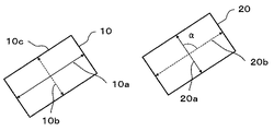
例えば、図2は、本発明の一態様における、偏光子の吸収軸の関係を例示する図である。図2において、背面側偏光板10における第1偏光子の吸収軸は10aで表され、第1偏光子の透過軸は10bで表される。また、背面側偏光板の長辺は、10cで示される。一方、図2において、前面側偏光板20の第2偏光子の吸収軸は20aで表され、第2偏光子の透過軸は20bで表される。
本発明においては、第1偏光子の吸収軸10aと、第2偏光子の吸収軸20aとのなす角度は、上述のように、90°±1°である。この角度は、例えば、図2における角度αとして表すことができる。
For example, FIG. 2 is a diagram illustrating the relationship between the absorption axes of the polarizer in one aspect of the present invention. In FIG. 2, the absorption axis of the first polarizing element in the back-side
In the present invention, the angle formed by the
一態様においては、背面側偏光板における第1偏光子の吸収軸と、前記背面側偏光板(第1偏光子)の長辺とのなす角度は0°±1°であり、別の態様では、上記なす角度は0°±0.5°である。 In one embodiment, the angle formed by the absorption axis of the first polarizing element in the back side polarizing plate and the long side of the back side polarizing plate (first polarizing element) is 0 ° ± 1 °, and in another aspect. The angle formed above is 0 ° ± 0.5 °.
なお、本発明において、前面側偏光板における第2偏光子の吸収軸を、前面側偏光板の吸収軸と記載することがあり、また、背面側偏光板における第1偏光子の吸収軸を、背面側偏光板の吸収軸とすることがある。 In the present invention, the absorption axis of the second polarizer in the front polarizing plate may be described as the absorption axis of the front polarizing plate, and the absorption axis of the first polarizing element in the back polarizing plate may be referred to as the absorption axis of the first polarizing element in the back polarizing plate. It may be the absorption axis of the back side polarizing plate.
本発明の偏光板セットにおいて、前面側偏光板における第2偏光子の厚さdF(μm)から、背面側偏光板における第1偏光子の厚さdR(μm)を差し引いた差dF−dRをΔd(μm)とした場合、
0μm<Δd<5μmであることにより、例えば、前面側偏光板とガラス板と背面側偏光板を有する液晶パネルを、高温条件下、湿熱環境下に曝したとしても、これらの反りを抑制できる。
In the polarizing plate set of the present invention, the difference dF-dR obtained by subtracting the thickness dR (μm) of the first polarizing element of the back side polarizing plate from the thickness dF (μm) of the second polarizer in the front side polarizing plate is obtained. When Δd (μm)
When 0 μm <Δd <5 μm, for example, even if a liquid crystal panel having a front-side polarizing plate, a glass plate, and a back-side polarizing plate is exposed to a moist heat environment under high temperature conditions, these warpages can be suppressed.
なお、本発明における偏光板を高温条件下に曝し、偏光板に僅かな反りが生じ得る場合、例えば、反射型偏光板、第1粘着剤層、第1偏光子、第1保護フィルムおよび第2粘着剤層は一体となって反り得る。同様に、第3粘着剤層、第2偏光子および第2保護フィルムは一体となって反り得る。
したがって、本発明における背面側偏光板と、前面側偏光板は、通常、これらの層間の少なくとも1つの層間において層間剥離は生じ得ない。
なお、背面側偏光板または前面側偏光板のいずれか一方に反りが生じ得る場合があり、背面側偏光板または前面側偏光板が共に反り得る場合がある。
When the polarizing plate in the present invention is exposed to high temperature conditions and the polarizing plate may be slightly warped, for example, a reflective polarizing plate, a first pressure-sensitive adhesive layer, a first polarizing element, a first protective film and a second protective film are used. The pressure-sensitive adhesive layer can warp together. Similarly, the third pressure-sensitive adhesive layer, the second polarizer and the second protective film can warp together.
Therefore, the back-side polarizing plate and the front-side polarizing plate in the present invention cannot usually undergo delamination between at least one of these layers.
In addition, either the back side polarizing plate or the front side polarizing plate may be warped, and both the back side polarizing plate and the front side polarizing plate may be warped.
このような反りについて、本発明においては、反り量等を測定することにより評価できる。例えば、この反り量は、湿熱条件における反り量を測定することにより評価してもよく、高温条件における反り量を測定することにより評価してもよい。
例えば、湿熱条件における反り量を測定する場合、前面側偏光板の第3粘着剤と背面側偏光板の第2粘着層をガラスパネルの表裏に貼合せ、60℃、湿度90%の環境下に250時間静置した後、ガラスパネルを背面側偏光板が下になるように設置し、測定台の水平面からの浮き上がりの相対高さを測定したものである。
In the present invention, such warpage can be evaluated by measuring the amount of warpage and the like. For example, this amount of warpage may be evaluated by measuring the amount of warpage under moist heat conditions, or may be evaluated by measuring the amount of warpage under high temperature conditions.
For example, when measuring the amount of warpage under moist heat conditions, the third adhesive of the front polarizing plate and the second adhesive layer of the back polarizing plate are attached to the front and back of the glass panel, and the temperature is 60 ° C. and the humidity is 90%. After allowing to stand for 250 hours, the glass panel was installed so that the backside polarizing plate was on the bottom, and the relative height of the floating of the measuring table from the horizontal plane was measured.
例えば、高温状態における反り量を測定する場合、前面側偏光板の第3粘着剤と背面側偏光板の第2粘着層をガラスパネルの表裏に貼合せ、85℃、湿度5%の環境下に250時間静置した後、背面側偏光板が下になるようにガラスパネルを設置し、測定台の水平面からの浮き上がりの相対高さを測定したものである。 For example, when measuring the amount of warpage in a high temperature state, the third adhesive of the front polarizing plate and the second adhesive layer of the back polarizing plate are attached to the front and back of the glass panel, and the temperature is 85 ° C. and the humidity is 5%. After allowing to stand for 250 hours, a glass panel was installed so that the back side polarizing plate was on the bottom, and the relative height of the floating of the measuring table from the horizontal plane was measured.
[反射型偏光板]
反射型偏光板は、輝度向上フィルムとも称され、光源(バックライト)からの出射光を透過偏光と反射偏光または散乱偏光に分離するような機能を有する偏光変換素子が用いられる。上述のように、反射型偏光板と偏光子を所定の関係で配置することにより、反射偏光または散乱偏光である再帰光を利用して、偏光子から出射される直線偏光の出射効率を向上させることができる。例えば反射型偏光板は、第1粘着剤層に接して積層される。
[Reflective polarizing plate]
The reflective polarizing plate is also called a brightness improving film, and a polarization conversion element having a function of separating the emitted light from a light source (backlight) into transmitted polarized light and reflected polarized light or scattered polarized light is used. As described above, by arranging the reflective polarizing plate and the polarizer in a predetermined relationship, the emission efficiency of the linearly polarized light emitted from the polarizer is improved by utilizing the retrolight which is the reflected polarized light or the scattered polarized light. be able to. For example, the reflective polarizing plate is laminated in contact with the first pressure-sensitive adhesive layer.
反射型偏光板は、例えば、異方性反射偏光子であることができる。異方性反射偏光子の一例は、一方の振動方向の直線偏光を透過し、他方の振動方向の直線偏光を反射する異方性多重薄膜であり、その具体例は3M社製のDBEFである(特開平4−268505号公報等)。このような反射型偏光板は、屈折率異方性が異なる少なくとも2層の薄膜で構成された多層積層体を延伸してなる反射型偏光板である。よって、このような反射型偏光板は、少なくとも2層の薄膜を有し、延伸された少なくとも2層の薄膜は、屈折率異方性が異なるものである。 The reflective polarizing plate can be, for example, an anisotropic reflective polarizer. An example of an anisotropic reflective polarizer is an anisotropic multilayer thin film that transmits linearly polarized light in one vibration direction and reflects linearly polarized light in the other vibration direction, and a specific example thereof is DBEF manufactured by 3M. (Japanese Patent Laid-Open No. 4-268505, etc.). Such a reflective polarizing plate is a reflective polarizing plate formed by stretching a multilayer laminate composed of at least two thin films having different refractive index anisotropy. Therefore, such a reflective polarizing plate has at least two thin films, and the stretched at least two thin films have different refractive index anisotropy.
異方性反射偏光子の他の一例は、コレステリック液晶層とλ/4板との複合体であり、その具体例は日東電工株式会社製のPCFである(特開平11−231130号公報等)。異方性反射偏光子のさらに他の一例は、反射グリッド偏光子であり、その具体例は、金属に微細加工を施して可視光領域でも反射偏光を出射するような金属格子反射偏光子(米国特許第6288840号明細書等)、金属微粒子を高分子マトリックス中に添加して延伸したフィルム(特開平8−184701号公報)である。 Another example of the anisotropic reflection polarizer is a complex of a cholesteric liquid crystal layer and a λ / 4 plate, and a specific example thereof is a PCF manufactured by Nitto Denko KK (Japanese Patent Laid-Open No. 11-231130, etc.). .. Yet another example of the anisotropic reflection polarizer is a reflection grid polarizer, a specific example of which is a metal lattice reflection polarizer (USA) in which a metal is finely processed to emit reflected polarized light even in the visible light region. Patent No. 6288840, etc.), a film obtained by adding fine metal particles into a polymer matrix and stretching it (Japanese Patent Laid-Open No. 8-184701).
反射型偏光板における第1粘着剤層とは反対側の面に、ハードコート層、防眩層、光拡散層、1/4波長の位相差値を持つ位相差層のような光学層を設けてもよい。光学層の形成により、バックライトテープとの密着性や表示画像の均一性を向上させ得る。反射型偏光板の厚みは、5〜100μm程度であることができるが、液晶パネルとしての反りを低減する観点から、好ましくは10〜40μm、より好ましくは10〜30μmである。 An optical layer such as a hard coat layer, an antiglare layer, a light diffusion layer, and a retardation layer having a retardation value of 1/4 wavelength is provided on the surface of the reflective polarizing plate on the side opposite to the first pressure-sensitive adhesive layer. You may. By forming the optical layer, the adhesion to the backlight tape and the uniformity of the displayed image can be improved. The thickness of the reflective polarizing plate can be about 5 to 100 μm, but is preferably 10 to 40 μm, more preferably 10 to 30 μm from the viewpoint of reducing warpage of the liquid crystal panel.
本発明の偏光板セットにおいて、反射型偏光板における第1粘着剤層側の表面には表面活性化処理が施され得る。この表面活性化処理は、反射型偏光板と第1粘着剤層との貼合に先立って行われる。これにより、湿熱環境下において第1粘着剤層と反射型偏光板との間での剥がれが生じにくい、湿熱耐久性に優れた偏光板が得られる。 In the polarizing plate set of the present invention, the surface of the reflective polarizing plate on the side of the first pressure-sensitive adhesive layer can be subjected to a surface activation treatment. This surface activation treatment is performed prior to the bonding of the reflective polarizing plate and the first pressure-sensitive adhesive layer. As a result, a polarizing plate having excellent moist heat durability can be obtained, in which peeling between the first pressure-sensitive adhesive layer and the reflective polarizing plate is unlikely to occur in a moist heat environment.
表面活性化処理は、表面の親水化処理であることができ、乾式処理でもよいし湿式処理でもよい。乾式処理としては、例えば、コロナ処理、プラズマ処理、グロー放電処理のような放電処理;火炎処理;オゾン処理;UVオゾン処理;紫外線処理、電子線処理のような電離活性線処理等が挙げられる。湿式処理としては、例えば、水やアセトンのような溶媒を用いた超音波処理、アルカリ処理、アンカーコート処理等を例示できる。これらの処理は、単独で行ってもよいし、2つ以上を組み合わせて行ってもよい。 The surface activation treatment can be a surface hydrophilic treatment, and may be a dry treatment or a wet treatment. Examples of the dry treatment include discharge treatment such as corona treatment, plasma treatment, and glow discharge treatment; flame treatment; ozone treatment; UV ozone treatment; ultraviolet treatment, ionization active ray treatment such as electron beam treatment, and the like. Examples of the wet treatment include ultrasonic treatment using a solvent such as water and acetone, alkali treatment, and anchor coating treatment. These processes may be performed alone or in combination of two or more.
中でも、湿熱環境下における反射型偏光板の剥がれ抑制効果および偏光板の生産性の観点から、表面活性化処理は、コロナ処理および/またはプラズマ処理であることが好ましい。これらの表面活性化処理によれば、反射型偏光板の厚みが薄く、例えば30μm以下の場合であっても、湿熱環境下における第1粘着剤層と反射型偏光板との間での剥がれを効果的に抑制することができる。なお、第1粘着剤層における輝度反射型偏光板側の表面にも表面活性化処理を併せて施してもよい。 Above all, from the viewpoint of the effect of suppressing peeling of the reflective polarizing plate in a moist heat environment and the productivity of the polarizing plate, the surface activation treatment is preferably corona treatment and / or plasma treatment. According to these surface activation treatments, even when the thickness of the reflective polarizing plate is thin, for example, 30 μm or less, peeling between the first pressure-sensitive adhesive layer and the reflective polarizing plate in a moist heat environment can be prevented. It can be effectively suppressed. The surface of the first pressure-sensitive adhesive layer on the luminance-reflecting polarizing plate side may also be subjected to a surface activation treatment.
[第1粘着剤層]
第1粘着剤層は、第1偏光子と反射型偏光板との間に介在する層である。第1粘着剤層は、典型的には、第1偏光子と第1粘着剤層とが接するように偏光子に直接積層される。第1粘着剤層は、アクリル系、ゴム系、ウレタン系、エステル系、シリコーン系、ポリビニルエーテル系のような樹脂を主成分とする粘着剤組成物で構成することができる。中でも、透明性、耐候性、耐熱性等に優れるアクリル系樹脂をベースポリマーとする粘着剤組成物が好適である。粘着剤組成物は、活性エネルギー線硬化型、熱硬化型であってもよい。
[First adhesive layer]
The first pressure-sensitive adhesive layer is a layer interposed between the first polarizing element and the reflective polarizing plate. The first pressure-sensitive adhesive layer is typically laminated directly on the polarizer so that the first polarizer and the first pressure-sensitive adhesive layer are in contact with each other. The first pressure-sensitive adhesive layer can be composed of a pressure-sensitive adhesive composition containing a resin as a main component, such as acrylic-based, rubber-based, urethane-based, ester-based, silicone-based, and polyvinyl ether-based. Among them, a pressure-sensitive adhesive composition using an acrylic resin having excellent transparency, weather resistance, heat resistance and the like as a base polymer is preferable. The pressure-sensitive adhesive composition may be an active energy ray-curable type or a thermosetting type.
上記アクリル系ベースポリマーとしては、例えば、(メタ)アクリル酸ブチル、(メタ)アクリル酸エチル、(メタ)アクリル酸イソオクチル、(メタ)アクリル酸2−エチルヘキシルのような(メタ)アクリル酸エステル系ベースポリマーや、これらの(メタ)アクリル酸エステルを2種類以上用いた共重合系ベースポリマーが好適に用いられる。ベースポリマーには、極性モノマーを共重合させることが好ましい。極性モノマーとしては、例えば、(メタ)アクリル酸、(メタ)アクリル酸2−ヒドロキシプロピル、(メタ)アクリル酸ヒドロキシエチル、(メタ)アクリルアミド、N,N−ジメチルアミノエチル(メタ)アクリレート、グリシジル(メタ)アクリレートのような、カルボキシル基、水酸基、アミド基、アミノ基、エポキシ基等を有するモノマーを挙げることができる。 Examples of the acrylic base polymer include (meth) acrylic acid ester-based polymers such as butyl (meth) acrylate, ethyl (meth) acrylate, isooctyl (meth) acrylate, and 2-ethylhexyl (meth) acrylate. Polymers and copolymer-based base polymers using two or more of these (meth) acrylic acid esters are preferably used. It is preferable that the base polymer is copolymerized with a polar monomer. Examples of the polar monomer include (meth) acrylic acid, 2-hydroxypropyl (meth) acrylate, hydroxyethyl (meth) acrylate, (meth) acrylamide, N, N-dimethylaminoethyl (meth) acrylate, and glycidyl (). Examples thereof include monomers having a carboxyl group, a hydroxyl group, an amide group, an amino group, an epoxy group and the like, such as meta) acrylate.
粘着剤組成物は通常、架橋剤をさらに含有する。架橋剤としては、2価以上の金属イオンであって、カルボキシル基との間でカルボン酸金属塩を形成するもの;ポリアミン化合物であって、カルボキシル基との間でアミド結合を形成するもの;ポリエポキシ化合物やポリオールであって、カルボキシル基との間でエステル結合を形成するもの;ポリイソシアネート化合物であって、カルボキシル基との間でアミド結合を形成するものが例示される。中でも、ポリイソシアネート化合物が好ましい。 The pressure-sensitive adhesive composition usually further contains a cross-linking agent. The cross-linking agent is a divalent or higher metal ion that forms a carboxylic acid metal salt with a carboxyl group; a polyamine compound that forms an amide bond with a carboxyl group; poly. Epoxy compounds and polyols that form an ester bond with a carboxyl group; polyisocyanate compounds that form an amide bond with a carboxyl group are exemplified. Of these, polyisocyanate compounds are preferable.
活性エネルギー線硬化型粘着剤組成物とは、紫外線や電子線のような活性エネルギー線の照射を受けて硬化する性質を有しており、活性エネルギー線照射前においても粘着性を有してフィルム等の被着体に密着させることができ、活性エネルギー線の照射によって硬化して密着力の調整ができる性質を有する粘着剤組成物である。活性エネルギー線硬化型粘着剤組成物は、紫外線硬化型であることが好ましい。活性エネルギー線硬化型粘着剤組成物は、ベースポリマー、架橋剤に加えて、活性エネルギー線重合性化合物をさらに含有する。さらに必要に応じて、光重合開始剤や光増感剤等を含有させることもある。 The active energy ray-curable pressure-sensitive adhesive composition has a property of being cured by being irradiated with active energy rays such as ultraviolet rays and electron beams, and has adhesiveness even before irradiation with active energy rays. It is a pressure-sensitive adhesive composition having the property of being able to adhere to an adherend such as, etc., and being cured by irradiation with active energy rays to adjust the adhesion force. The active energy ray-curable pressure-sensitive adhesive composition is preferably an ultraviolet-curable type. The active energy ray-curable pressure-sensitive adhesive composition further contains an active energy ray-polymerizable compound in addition to the base polymer and the cross-linking agent. Further, if necessary, a photopolymerization initiator, a photosensitizer, or the like may be contained.
粘着剤組成物は、光散乱性を付与するための微粒子;ビーズ;ベースポリマー以外の樹脂;粘着性付与剤;充填剤;酸化防止剤;紫外線吸収剤;顔料;着色剤等の添加剤を含むことができる。 The pressure-sensitive adhesive composition contains fine particles for imparting light scattering properties; beads; resins other than the base polymer; pressure-sensitive adhesives; fillers; antioxidants; ultraviolet absorbers; pigments; additives such as colorants. be able to.
第1粘着剤層は、上記粘着剤組成物の有機溶剤希釈液を基材上に塗布し、乾燥させることにより形成することができる。基材は、偏光子、反射型偏光板、セパレータ等であることができる。活性エネルギー線硬化型粘着剤組成物を用いた場合は、形成された粘着剤層に、活性エネルギー線を照射することにより所望の硬化物とすることができる。 The first pressure-sensitive adhesive layer can be formed by applying an organic solvent diluted solution of the above-mentioned pressure-sensitive adhesive composition on a substrate and drying it. The base material can be a polarizer, a reflective polarizing plate, a separator, or the like. When the active energy ray-curable pressure-sensitive adhesive composition is used, the formed pressure-sensitive adhesive layer can be irradiated with active energy rays to obtain a desired cured product.
第1粘着剤層は、23〜80℃の温度範囲において0.15〜1.2MPaの貯蔵弾性率を示すものであることが好ましい。これにより、高温および湿熱環境下において偏光子の収縮に伴って発生しやすい寸法変化を抑制して、偏光板の耐久性を高めることができる。また、偏光板を搭載した液晶パネル(例えば中小型モバイル端末用の液晶パネル)が高温および湿熱環境下に置かれた場合にも、偏光板の動きが抑制されるので、液晶パネルの信頼性を高めることができる。 The first pressure-sensitive adhesive layer preferably exhibits a storage elastic modulus of 0.15 to 1.2 MPa in a temperature range of 23 to 80 ° C. As a result, the durability of the polarizing plate can be improved by suppressing the dimensional change that tends to occur with the shrinkage of the polarizing element in a high temperature and moist heat environment. In addition, even when a liquid crystal panel equipped with a polarizing plate (for example, a liquid crystal panel for small and medium-sized mobile terminals) is placed in a high temperature and moist heat environment, the movement of the polarizing plate is suppressed, so that the reliability of the liquid crystal panel can be improved. Can be enhanced.
「23〜80℃の温度範囲において0.15〜1.2MPaの貯蔵弾性率を示す」とは、この範囲のいずれの温度においても、貯蔵弾性率が上記範囲内の値であることを意味する。貯蔵弾性率は通常、温度上昇に伴って漸減するので、23℃および80℃における貯蔵弾性率がいずれも上記範囲に入っていれば、この範囲の温度において、上記範囲内の貯蔵弾性率を示すとみることができる。第1粘着剤層の貯蔵弾性率は、市販の粘弾性測定装置、例えば、後掲の実施例に示すようなREOMETRIC社製の粘弾性測定装置「DYNAMIC ANALYZER RDA II」を用いて測定することができる。 "Exhibiting a storage elastic modulus of 0.15 to 1.2 MPa in a temperature range of 23 to 80 ° C." means that the storage elastic modulus is a value within the above range at any temperature in this range. .. Since the storage elastic modulus usually gradually decreases as the temperature rises, if the storage elastic modulus at 23 ° C. and 80 ° C. is both within the above range, the storage elastic modulus within the above range is indicated at the temperature in this range. Can be seen as. The storage elastic modulus of the first pressure-sensitive adhesive layer can be measured using a commercially available viscoelasticity measuring device, for example, a viscoelasticity measuring device “DYNAMIC ANALYZER RDA II” manufactured by REOMETRIC as shown in the examples below. it can.
貯蔵弾性率を上記範囲に調整するための方法としては、ベースポリマーおよび架橋剤を含む粘着剤組成物に、オリゴマー、具体的には、ウレタンアクリレート系のオリゴマーをさらに添加して活性エネルギー線硬化型粘着剤組成物(好ましくは紫外線硬化型粘着剤組成物)とすることが挙げられる。より好ましくは、活性エネルギー線を照射して粘着剤層を適度に硬化させる。 As a method for adjusting the storage elastic modulus within the above range, an oligomer, specifically, a urethane acrylate-based oligomer is further added to a pressure-sensitive adhesive composition containing a base polymer and a cross-linking agent to form an active energy ray-curable type. A pressure-sensitive adhesive composition (preferably an ultraviolet curable pressure-sensitive adhesive composition) may be used. More preferably, the pressure-sensitive adhesive layer is appropriately cured by irradiating it with active energy rays.
第1粘着剤層の厚みは、30μm以下であり得る。好ましくは25μm以下、特に好ましくは20μm以下、とりわけ好ましくは15μm以下である。第1粘着剤層の厚みがこのような範囲にあることにより、良好な加工性を保ちつつ、偏光板の寸法変化を抑制できる。なお、第1粘着剤層の厚さは、上記層間厚みが所定の範囲となるように、適宜調整できる。 The thickness of the first pressure-sensitive adhesive layer can be 30 μm or less. It is preferably 25 μm or less, particularly preferably 20 μm or less, and particularly preferably 15 μm or less. When the thickness of the first pressure-sensitive adhesive layer is in such a range, it is possible to suppress a dimensional change of the polarizing plate while maintaining good processability. The thickness of the first pressure-sensitive adhesive layer can be appropriately adjusted so that the interlayer thickness is within a predetermined range.
[偏光子]
偏光子は、その吸収軸に平行な振動面をもつ直線偏光を吸収し、吸収軸に直交する(透過軸と平行な)振動面をもつ直線偏光を透過する性質を有する吸収型の偏光子である。本発明の偏光板セットに用いられる第1偏光子および第2偏光子は、その厚さが所定の関係を有する限り、同一の偏光子であってもよく、それぞれ異なる偏光子であってもよい。例えば、ポリビニルアルコール系樹脂フィルムに二色性色素を吸着配向させた偏光フィルムを好適に用いることができる。偏光子は、例えば、ポリビニルアルコール系樹脂フィルムを一軸延伸する工程;ポリビニルアルコール系樹脂フィルムを二色性色素で染色することにより二色性色素を吸着させる工程;二色性色素が吸着されたポリビニルアルコール系樹脂フィルムをホウ酸水溶液で処理する工程;および、ホウ酸水溶液による処理後に水洗する工程を含む方法によって製造できる。
[Polarizer]
A polarizer is an absorption-type polarized light having the property of absorbing linearly polarized light having a vibration plane parallel to its absorption axis and transmitting linearly polarized light having a vibration plane orthogonal to the absorption axis (parallel to the transmission axis). is there. The first and second polarizers used in the polarizing plate set of the present invention may be the same or different polarizers as long as their thicknesses have a predetermined relationship. .. For example, a polarizing film in which a dichroic dye is adsorbed and oriented on a polyvinyl alcohol-based resin film can be preferably used. The polarizer is, for example, a step of uniaxially stretching a polyvinyl alcohol-based resin film; a step of adsorbing a dichroic dye by dyeing the polyvinyl alcohol-based resin film with a dichroic dye; It can be produced by a method including a step of treating the alcohol-based resin film with an aqueous boric acid solution; and a step of washing with water after the treatment with the aqueous boric acid solution.
ポリビニルアルコール系樹脂としては、ポリ酢酸ビニル系樹脂をケン化したものを用いることができる。ポリ酢酸ビニル系樹脂としては、酢酸ビニルの単独重合体であるポリ酢酸ビニルの他、酢酸ビニルと共重合可能な他の単量体との共重合体等が挙げられる。酢酸ビニルに共重合可能な他の単量体の例は、不飽和カルボン酸類、オレフィン類、ビニルエーテル類、不飽和スルホン酸類およびアンモニウム基を有するアクリルアミド類等を含む。 As the polyvinyl alcohol-based resin, a saponified polyvinyl acetate-based resin can be used. Examples of the polyvinyl acetate-based resin include polyvinyl acetate, which is a homopolymer of vinyl acetate, and a copolymer of vinyl acetate and another monomer copolymerizable with the vinyl acetate. Examples of other monomers copolymerizable with vinyl acetate include unsaturated carboxylic acids, olefins, vinyl ethers, unsaturated sulfonic acids and acrylamides having an ammonium group.
ポリビニルアルコール系樹脂のケン化度は通常、85〜100mol%程度であり、98mol%以上が好ましい。ポリビニルアルコール系樹脂は変性されていてもよく、例えば、アルデヒド類で変性されたポリビニルホルマールまたはポリビニルアセタール等を用いることもできる。ポリビニルアルコール系樹脂の平均重合度は通常、1000〜10000程度であり、1500〜5000程度が好ましい。ポリビニルアルコール系樹脂の平均重合度は、JIS K 6726に準拠して求めることができる。 The saponification degree of the polyvinyl alcohol-based resin is usually about 85 to 100 mol%, preferably 98 mol% or more. The polyvinyl alcohol-based resin may be modified, and for example, polyvinyl formal or polyvinyl acetal modified with aldehydes can be used. The average degree of polymerization of the polyvinyl alcohol-based resin is usually about 1000 to 10000, preferably about 1500 to 5000. The average degree of polymerization of the polyvinyl alcohol-based resin can be determined in accordance with JIS K 6726.
このようなポリビニルアルコール系樹脂を製膜したものが、偏光子(偏光フィルム)の原反フィルムとして用いられる。ポリビニルアルコール系樹脂を製膜する方法は、特に限定されるものではなく、公知の方法が採用される。ポリビニルアルコール系原反フィルムの厚みは特に制限されないが、偏光子の厚みを、例えば15μm以下とするためには、5〜35μm程度の原反フィルムを用いることが好ましい。 A film formed of such a polyvinyl alcohol-based resin is used as a raw film for a polarizing element (polarizing film). The method for forming a film of the polyvinyl alcohol-based resin is not particularly limited, and a known method is adopted. The thickness of the polyvinyl alcohol-based raw film is not particularly limited, but in order to reduce the thickness of the polarizer to, for example, 15 μm or less, it is preferable to use a raw film having a thickness of about 5 to 35 μm.
ポリビニルアルコール系樹脂フィルムの一軸延伸は、二色性色素の染色前、染色と同時、または染色の後に行うことができる。一軸延伸を染色の後で行う場合、この一軸延伸は、ホウ酸処理の前またはホウ酸処理中に行ってもよい。また、これらの複数の段階で一軸延伸を行ってもよい。 The uniaxial stretching of the polyvinyl alcohol-based resin film can be performed before dyeing the dichroic dye, at the same time as dyeing, or after dyeing. If the uniaxial stretching is performed after staining, the uniaxial stretching may be performed before the boric acid treatment or during the boric acid treatment. Moreover, uniaxial stretching may be performed in these a plurality of steps.
一軸延伸にあたっては、周速の異なるロール間で一軸に延伸してもよいし、熱ロールを用いて一軸に延伸してもよい。また一軸延伸は、大気中で延伸を行う乾式延伸であってもよいし、溶剤を用いてポリビニルアルコール系樹脂フィルムを膨潤させた状態で延伸を行う湿式延伸であってもよい。延伸倍率は通常、3〜8倍程度である。 In uniaxial stretching, rolls having different peripheral speeds may be uniaxially stretched, or thermal rolls may be used to uniaxially stretch the rolls. The uniaxial stretching may be a dry stretching in which the film is stretched in the atmosphere, or a wet stretching in which the polyvinyl alcohol-based resin film is swollen with a solvent. The draw ratio is usually about 3 to 8 times.
ポリビニルアルコール系樹脂フィルムを二色性色素で染色する方法としては、例えば、該フィルムを二色性色素が含有された水溶液に浸漬する方法が採用される。二色性色素として、ヨウ素や二色性有機染料が用いられる。なお、ポリビニルアルコール系樹脂フィルムは、染色処理の前に水への浸漬処理を施しておくことが好ましい。 As a method of dyeing a polyvinyl alcohol-based resin film with a dichroic dye, for example, a method of immersing the film in an aqueous solution containing a dichroic dye is adopted. As the dichroic dye, iodine or a dichroic organic dye is used. The polyvinyl alcohol-based resin film is preferably immersed in water before the dyeing treatment.
ヨウ素による染色処理としては通常、ヨウ素およびヨウ化カリウムを含有する水溶液に、ポリビニルアルコール系樹脂フィルムを浸漬する方法が採用される。この水溶液におけるヨウ素の含有量は、水100重量部あたり0.01〜1重量部程度であることができる。ヨウ化カリウムの含有量は、水100重量部あたり0.5〜20重量部程度であることができる。また、この水溶液の温度は、20〜40℃程度であることができる。一方、二色性有機染料による染色処理としては通常、二色性有機染料を含有する水溶液に、ポリビニルアルコール系樹脂フィルムを浸漬する方法が採用される。二色性有機染料を含有する水溶液は、硫酸ナトリウム等の無機塩を染色助剤として含有していてもよい。この水溶液における二色性有機染料の含有量は、水100重量部あたり1×10⁻⁴〜10重量部程度であることができる。この水溶液の温度は、20〜80℃程度であることができる。 As the dyeing treatment with iodine, a method of immersing a polyvinyl alcohol-based resin film in an aqueous solution containing iodine and potassium iodide is usually adopted. The iodine content in this aqueous solution can be about 0.01 to 1 part by weight per 100 parts by weight of water. The content of potassium iodide can be about 0.5 to 20 parts by weight per 100 parts by weight of water. The temperature of this aqueous solution can be about 20 to 40 ° C. On the other hand, as a dyeing treatment with a dichroic organic dye, a method of immersing a polyvinyl alcohol-based resin film in an aqueous solution containing a dichroic organic dye is usually adopted. The aqueous solution containing the dichroic organic dye may contain an inorganic salt such as sodium sulfate as a dyeing aid. The content of the dichroic organic dye in this aqueous solution can be about 1 × 10 -4 to 10 parts by weight per 100 parts by weight of water. The temperature of this aqueous solution can be about 20 to 80 ° C.
二色性色素による染色後のホウ酸処理としては通常、染色されたポリビニルアルコール系樹脂フィルムをホウ酸含有水溶液に浸漬する方法が採用される。二色性色素としてヨウ素を用いる場合、このホウ酸含有水溶液は、ヨウ化カリウムを含有することが好ましい。ホウ酸含有水溶液におけるホウ酸の量は、水100重量部あたり2〜15重量部程度であることができる。この水溶液におけるヨウ化カリウムの量は、水100重量部あたり0.1〜15重量部程度であることができる。この水溶液の温度は、50℃以上であることができ、例えば50〜85℃である。 As the boric acid treatment after dyeing with a dichroic dye, a method of immersing the dyed polyvinyl alcohol-based resin film in a boric acid-containing aqueous solution is usually adopted. When iodine is used as the dichroic pigment, the boric acid-containing aqueous solution preferably contains potassium iodide. The amount of boric acid in the boric acid-containing aqueous solution can be about 2 to 15 parts by weight per 100 parts by weight of water. The amount of potassium iodide in this aqueous solution can be about 0.1 to 15 parts by weight per 100 parts by weight of water. The temperature of this aqueous solution can be 50 ° C. or higher, for example 50-85 ° C.
ホウ酸処理後のポリビニルアルコール系樹脂フィルムは通常、水洗処理される。水洗処理は、例えば、ホウ酸処理されたポリビニルアルコール系樹脂フィルムを水に浸漬することにより行うことができる。水洗処理は、ヨウ化カリウムを含有する水により行ってもよい水洗処理における水の温度は通常、5〜40℃程度である。 The polyvinyl alcohol-based resin film after the boric acid treatment is usually washed with water. The water washing treatment can be performed, for example, by immersing the boric acid-treated polyvinyl alcohol-based resin film in water. The water washing treatment may be carried out with water containing potassium iodide. The temperature of the water in the water washing treatment is usually about 5 to 40 ° C.
水洗後に乾燥処理を施して、偏光子が得られる。乾燥処理は、熱風乾燥機や遠赤外線ヒーターを用いて行うことができる。偏光子の厚みは15μm以下であることが好ましく、13μm以下であることがより好ましい。偏光子の厚みは通常、4μm以上である。一態様においては、背面側偏光板における第1偏光子の厚さdRは、15μm以下である。一態様においては、前面側偏光板における第2偏光子の厚さdFは、15μm以下であり、より好ましくは、0.1μm以上13μm以下である。
なお、偏光子の厚さは、本発明の範囲を逸脱しない範囲となるように、適宜調整できる。
After washing with water, it is dried to obtain a polarizer. The drying process can be performed using a hot air dryer or a far-infrared heater. The thickness of the polarizer is preferably 15 μm or less, more preferably 13 μm or less. The thickness of the polarizer is usually 4 μm or more. In one aspect, the thickness dR of the first polarizer in the back side polarizing plate is 15 μm or less. In one aspect, the thickness dF of the second polarizing element in the front polarizing plate is 15 μm or less, more preferably 0.1 μm or more and 13 μm or less.
The thickness of the polarizer can be appropriately adjusted so as not to deviate from the scope of the present invention.
[保護フィルム]
第1保護フィルムは、第1偏光子における第1粘着剤層とは反対側の面に積層されるフィルムである。第2保護フィルムは、第2偏光子における第3粘着剤層とは反対側の面に積層されるフィルムである。第1保護フィルムおよび第2保護フィルムは同一のフィルムであってもよく、異なるフィルムであってもよい。
保護フィルムは、透光性を有する(好ましくは光学的に透明な)熱可塑性樹脂、例えば、鎖状ポリオレフィン系樹脂(ポリプロピレン系樹脂等)、環状ポリオレフィン系樹脂(ノルボルネン系樹脂等)のようなポリオレフィン系樹脂;トリアセチルセルロース、ジアセチルセルロースのようなセルロース系樹脂;ポリエチレンテレフタレート、ポリブチレンテレフタレートのようなポリエステル系樹脂;ポリカーボネート系樹脂;(メタ)アクリル系樹脂のようなアクリル系樹脂;ポリスチレン系樹脂;ポリ塩化ビニル系樹脂;アクリロニトリル・ブタジエン・スチレン系樹脂;アクリロニトリル・スチレン系樹脂;ポリ酢酸ビニル系樹脂;ポリ塩化ビニリデン系樹脂;ポリアミド系樹脂;ポリアセタール系樹脂;変性ポリフェニレンエーテル系樹脂;ポリスルホン系樹脂;ポリエーテルスルホン系樹脂;ポリアリレート系樹脂;ポリアミドイミド系樹脂;ポリイミド系樹脂等からなるフィルムであることができる。中でも、ポリオレフィン系樹脂またはアクリル系樹脂を用いることが好ましく、特に好ましくは環状ポリオレフィン系樹脂を用いることが好ましい。
[Protective film]
The first protective film is a film laminated on the surface of the first polarizing element opposite to the first pressure-sensitive adhesive layer. The second protective film is a film laminated on the surface of the second polarizing element opposite to the third pressure-sensitive adhesive layer. The first protective film and the second protective film may be the same film or different films.
The protective film is a translucent (preferably optically transparent) thermoplastic resin, for example, a polyolefin such as a chain polyolefin resin (polypropylene resin or the like) or a cyclic polyolefin resin (norbornen resin or the like). Resins; Cellulosic resins such as triacetyl cellulose and diacetyl cellulose; Polyester resins such as polyethylene terephthalate and polybutylene terephthalate; Polycarbonate resins; Acrylic resins such as (meth) acrylic resins; Polystyrene resins; Polyvinyl chloride resin; Acrylonitrile / butadiene / styrene resin; Acrylonitrile / styrene resin; Polyvinyl acetate resin; Polyvinylidene chloride resin; Polyamide resin; Polyacetal resin; Modified polyphenylene ether resin; Polysulfone resin; A film made of a polyether sulfone-based resin; a polyarylate-based resin; a polyamide-based resin; a polyimide-based resin, or the like can be used. Of these, it is preferable to use a polyolefin-based resin or an acrylic-based resin, and particularly preferably a cyclic polyolefin-based resin.
鎖状ポリオレフィン系樹脂としては、ポリエチレン樹脂、ポリプロピレン樹脂のような鎖状オレフィンの単独重合体のほか、2種以上の鎖状オレフィンからなる共重合体を挙げることができる。 Examples of the chain polyolefin resin include homopolymers of chain olefins such as polyethylene resin and polypropylene resin, and copolymers composed of two or more kinds of chain olefins.
環状ポリオレフィン系樹脂は、環状オレフィンを重合単位として重合される樹脂の総称である。環状ポリオレフィン系樹脂の具体例を挙げれば、環状オレフィンの開環(共)重合体、環状オレフィンの付加重合体、環状オレフィンとエチレン、プロピレンのような鎖状オレフィンとの共重合体(代表的にはランダム共重合体)、およびこれらを不飽和カルボン酸やその誘導体で変性したグラフト重合体、並びにそれらの水素化物等である。中でも、環状オレフィンとしてノルボルネンや多環ノルボルネン系モノマー等のノルボルネン系モノマーを用いたノルボルネン系樹脂が好ましく用いられる。好ましい態様において、本発明に係る保護フィルムは、環状ポリオレフィン系樹脂を含む。 Cyclic polyolefin resin is a general term for resins that are polymerized using cyclic olefin as a polymerization unit. Specific examples of the cyclic polyolefin resin include an open (co) polymer of a cyclic olefin, an addition polymer of a cyclic olefin, and a copolymer of a cyclic olefin and a chain olefin such as ethylene and propylene (typically). Is a random copolymer), a graft polymer obtained by modifying these with an unsaturated carboxylic acid or a derivative thereof, and a hydride thereof. Of these, a norbornene-based resin using a norbornene-based monomer such as norbornene or a polycyclic norbornene-based monomer is preferably used as the cyclic olefin. In a preferred embodiment, the protective film according to the present invention contains a cyclic polyolefin resin.
セルロース系樹脂とは、綿花リンタや木材パルプ(広葉樹パルプ、針葉樹パルプ)等の原料セルロースから得られるセルロースの水酸基における水素原子の一部または全部がアセチル基、プロピオニル基および/またはブチリル基で置換された、セルロース有機酸エステルまたはセルロース混合有機酸エステルをいう。例えば、セルロースの酢酸エステル、プロピオン酸エステル、酪酸エステル、およびそれらの混合エステル等からなるものが挙げられる。 The cellulosic resin is obtained by substituting a part or all of hydrogen atoms in the hydroxyl groups of cellulose obtained from raw material cellulose such as cotton linter and wood pulp (perforated tree pulp, coniferous tree pulp) with acetyl group, propionyl group and / or butyryl group. Also, it refers to a cellulose organic acid ester or a cellulose mixed organic acid ester. For example, those composed of acetic acid ester of cellulose, propionic acid ester, butyric acid ester, mixed ester thereof and the like can be mentioned.
アクリル系樹脂フィルムの好ましい具体例としては、メタクリル酸メチル系樹脂を含むフィルムを挙げることができる。メタクリル酸メチル系樹脂とは、メタクリル酸メチル単位を50重量%以上含む重合体である。メタクリル酸メチル単位の含有量は、好ましくは70重量%以上であり、100重量%であってもよい。メタクリル酸メチル単位が100重量%の重合体は、メタクリル酸メチルを単独で重合させて得られるメタクリル酸メチル単独重合体である。 A preferable specific example of the acrylic resin film is a film containing a methyl methacrylate resin. The methyl methacrylate-based resin is a polymer containing 50% by weight or more of methyl methacrylate units. The content of the methyl methacrylate unit is preferably 70% by weight or more, and may be 100% by weight. The polymer having 100% by weight of methyl methacrylate is a methyl methacrylate homopolymer obtained by polymerizing methyl methacrylate alone.
このメタクリル酸メチル系樹脂は、通常、メタクリル酸メチルを主成分とする単官能単量体および必要に応じて使用される多官能単量体を、ラジカル重合開始剤および必要に応じて使用される連鎖移動剤の共存下に重合することにより得ることができる。 In this methyl methacrylate-based resin, a monofunctional monomer containing methyl methacrylate as a main component and a polyfunctional monomer used as needed are usually used as a radical polymerization initiator and, if necessary. It can be obtained by polymerizing in the presence of a chain transfer agent.
メタクリル酸メチルと共重合し得る単官能単量体としては、たとえば、メタクリル酸エチル、メタクリル酸ブチル、メタクリル酸シクロヘキシル、メタクリル酸フェニル、メタクリル酸ベンジル、メタクリル酸2−エチルヘキシル、およびメタクリル酸2−ヒドロキシエチル等のメタクリル酸メチル以外のメタクリル酸エステル類;アクリル酸メチル、アクリル酸エチル、アクリル酸ブチル、アクリル酸シクロヘキシル、アクリル酸フェニル、アクリル酸ベンジル、アクリル酸2−エチルヘキシル、およびアクリル酸2−ヒドロキシエチル等のアクリル酸エステル類;2−(ヒドロキシメチル)アクリル酸メチル、3−(ヒドロキシエチル)アクリル酸メチル、2−(ヒドロキシメチル)アクリル酸エチル、および2−(ヒドロキシメチル)アクリル酸ブチル等のヒドロキシアクリル酸エステル類;メタクリル酸およびアクリル酸等の不飽和酸類;クロロスチレンおよびブロモスチレン等のハロゲン化スチレン類;ビニルトルエンおよびα−メチルスチレン等の置換スチレン類;アクリロニトリルおよびメタクリロニトリル等の不飽和ニトリル類;無水マレイン酸および無水シトラコン酸等の不飽和酸無水物類;ならびにフェニルマレイミドおよびシクロヘキシルマレイミド等の不飽和イミド類等を挙げることができる。このような単量体は、それぞれ単独で用いられてもよいし、2種以上を組み合わせて用いられてもよい。 Monofunctional monomers capable of copolymerizing with methyl methacrylate include, for example, ethyl methacrylate, butyl methacrylate, cyclohexyl methacrylate, phenyl methacrylate, benzyl methacrylate, 2-ethylhexyl methacrylate, and 2-hydroxy methacrylate. Methacrylic acid esters other than methyl methacrylate such as ethyl; methyl acrylate, ethyl acrylate, butyl acrylate, cyclohexyl acrylate, phenyl acrylate, benzyl acrylate, 2-ethylhexyl acrylate, and 2-hydroxyethyl acrylate. Acrylic acid esters such as; methyl 2- (hydroxymethyl) acrylate, methyl 3- (hydroxyethyl) acrylate, ethyl 2- (hydroxymethyl) acrylate, and hydroxy such as butyl 2- (hydroxymethyl) acrylate. Acrylic acid esters; unsaturated acids such as methacrylic acid and acrylic acid; halogenated styrenes such as chlorostyrene and bromostyrene; substituted styrenes such as vinyltoluene and α-methylstyrene; unsaturateds such as acrylonitrile and methacrylic nitrile Examples thereof include nitriles; unsaturated acid anhydrides such as maleic anhydride and citraconic anhydride; and unsaturated imides such as phenylmaleimide and cyclohexylmaleimide. Such monomers may be used alone or in combination of two or more.
メタクリル酸メチルと共重合し得る多官能単量体としては、たとえば、エチレングリコールジ(メタ)アクリレート、ジエチレングリコールジ(メタ)アクリレート、トリエチレングリコールジ(メタ)アクリレート、テトラエチレングリコールジ(メタ)アクリレート、ノナエチレングリコールジ(メタ)アクリレート、およびテトラデカエチレングリコール(メタ)アクリレート等のエチレングリコールまたはそのオリゴマーの両末端水酸基をアクリル酸またはメタクリル酸でエステル化したもの;プロピレングリコールまたはそのオリゴマーの両末端水酸基をアクリル酸またはメタクリル酸でエステル化したもの;ネオペンチルグリコールジ(メタ)アクリレート、ヘキサンジオールジ(メタ)アクリレート、およびブタンジオールジ(メタ)アクリレート等の2価アルコールの水酸基をアクリル酸またはメタクリル酸でエステル化したもの;ビスフェノールA、ビスフェノールAのアルキレンオキシド付加物、またはこれらのハロゲン置換体の両末端水酸基をアクリル酸またはメタクリル酸でエステル化したもの;トリメチロールプロパンおよびペンタエリスリトール等の多価アルコールをアクリル酸またはメタクリル酸でエステル化したもの、ならびにこれら末端水酸基にグリシジルアクリレートまたはグリシジルメタクリレートのエポキシ基を開環付加させたもの;コハク酸、アジピン酸、テレフタル酸、フタル酸、これらのハロゲン置換体等の二塩基酸、およびこれらのアルキレンオキシド付加物等にグリシジルアクリレートまたはグリシジルメタクリレートのエポキシ基を開環付加させたもの;アリール(メタ)アクリレート;およびジビニルベンゼン等のジアリール化合物等が挙げられる。中でも、エチレングリコールジメタクリレート、テトラエチレングリコールジメタクリレートおよびネオペンチルグリコールジメタクリレートが好ましく用いられる。 Examples of the polyfunctional monomer copolymerizable with methyl methacrylate include ethylene glycol di (meth) acrylate, diethylene glycol di (meth) acrylate, triethylene glycol di (meth) acrylate, and tetraethylene glycol di (meth) acrylate. , Nonaethylene glycol di (meth) acrylate, and tetradecaethylene glycol (meth) acrylate and other ethylene glycols or oligomers thereof esterified with acrylic acid or methacrylic acid; both ends of propylene glycol or oligomers thereof. The hydroxyl group is esterified with acrylic acid or methacrylic acid; the hydroxyl group of a dihydric alcohol such as neopentyl glycol di (meth) acrylate, hexanediol di (meth) acrylate, and butanediol di (meth) acrylate is acrylic acid or methacrylic. Acid esterified; Bisphenol A, alkylene oxide adduct of Bisphenol A, or esterified hydroxyl groups at both ends of these halogen substituents with acrylic acid or methacrylic acid; Multivalent such as trimethylpropane and pentaerythritol Alcohol esterified with acrylic acid or methacrylic acid, and those having an epoxy group of glycidyl acrylate or glycidyl methacrylate added to these terminal hydroxyl groups by ring opening; succinic acid, adipic acid, terephthalic acid, phthalic acid, halogen substitutions thereof. Examples thereof include dibasic acids such as those obtained by ring-opening addition of an epoxy group of glycidyl acrylate or glycidyl methacrylate to dibasic acids such as these alkylene oxide adducts; aryl (meth) acrylates; and diaryl compounds such as divinylbenzene. Of these, ethylene glycol dimethacrylate, tetraethylene glycol dimethacrylate and neopentyl glycol dimethacrylate are preferably used.
メタクリル酸メチル系樹脂は、該樹脂が有する官能基間の反応を行なうことによって変性された変性メタクリル酸メチル系樹脂であってもよい。その反応としては、たとえば、アクリル酸メチルのメチルエステル基と2−(ヒドロキシメチル)アクリル酸メチルの水酸基との高分子鎖内脱メタノール縮合反応、および、アクリル酸のカルボキシル基と2−(ヒドロキシメチル)アクリル酸メチルの水酸基との高分子鎖内脱水縮合反応等が挙げられる。 The methyl methacrylate-based resin may be a modified methyl methacrylate-based resin modified by carrying out a reaction between the functional groups of the resin. The reactions include, for example, a demethanol condensation reaction in a polymer chain between a methyl ester group of methyl acrylate and a hydroxyl group of methyl 2- (hydroxymethyl) acrylate, and a carboxyl group of acrylic acid and 2- (hydroxymethyl). ) Intrapolymer chain dehydration condensation reaction with the hydroxyl group of methyl acrylate and the like can be mentioned.
保護フィルムの位相差値を、液晶パネルに好適な値に制御することも有用である。例えば、インプレーンスイッチング(IPS)モードの液晶パネルには、実質的に位相差値がゼロのフィルムを用いることが好ましい。実質的に位相差値がゼロとは、波長590nmにおける面内位相差値が10nm以下であり、波長590nmにおける厚み方向位相差値の絶対値が10nm以下であり、波長480〜750nmにおける厚み方向位相差値の絶対値が15nm以下であることをいう。 It is also useful to control the phase difference value of the protective film to a value suitable for the liquid crystal panel. For example, it is preferable to use a film having a substantially zero phase difference value for the liquid crystal panel in the in-plane switching (IPS) mode. When the phase difference value is substantially zero, the in-plane retardation value at a wavelength of 590 nm is 10 nm or less, the absolute value of the thickness direction retardation value at a wavelength of 590 nm is 10 nm or less, and the thickness direction position at a wavelength of 480 to 750 nm. It means that the absolute value of the phase difference value is 15 nm or less.
液晶パネルのモードによっては、保護フィルムに延伸および/または収縮加工を行い、好適な位相差値を付与してもよい。 Depending on the mode of the liquid crystal panel, the protective film may be stretched and / or shrunk to give a suitable retardation value.
保護フィルムの厚みは1〜30μm程度であることができるが、強度や取扱性等の観点から5〜25μmが好ましく、5〜20μmがより好ましい。この範囲内の厚みであれば、偏光子を機械的に保護し、湿熱環境下に曝されても偏光子が収縮せず、安定した光学特性を保つことができる。なお、保護フィルムの厚さは、上記層間厚みが所定の範囲となるように、適宜調整できる。 The thickness of the protective film can be about 1 to 30 μm, but is preferably 5 to 25 μm, more preferably 5 to 20 μm from the viewpoint of strength, handleability, and the like. If the thickness is within this range, the polarizer can be mechanically protected, the polarizer does not shrink even when exposed to a moist heat environment, and stable optical characteristics can be maintained. The thickness of the protective film can be appropriately adjusted so that the interlayer thickness is within a predetermined range.
保護フィルムは、接着剤層を介して偏光子に貼合することができる。接着剤層を形成する接着剤としては、水系接着剤または活性エネルギー線硬化性接着剤を用いることができる。 The protective film can be attached to the polarizer via an adhesive layer. As the adhesive forming the adhesive layer, a water-based adhesive or an active energy ray-curable adhesive can be used.
水系接着剤としては、ポリビニルアルコール系樹脂水溶液からなる接着剤、水系二液型ウレタン系エマルジョン接着剤等が挙げられる。中でもポリビニルアルコール系樹脂水溶液からなる水系接着剤が好適に用いられる。ポリビニルアルコール系樹脂としては、酢酸ビニルの単独重合体であるポリ酢酸ビニルをケン化処理して得られるビニルアルコールホモポリマーのほか、酢酸ビニルとこれに共重合可能な他の単量体との共重合体をケン化処理して得られるポリビニルアルコール系共重合体、またはそれらの水酸基を部分的に変性した変性ポリビニルアルコール系重合体等を用いることができる。水系接着剤は、アルデヒド化合物、エポキシ化合物、メラミン系化合物、メチロール化合物、イソシアネート化合物、アミン化合物、多価金属塩等の架橋剤を含むことができる。 Examples of the water-based adhesive include an adhesive composed of a polyvinyl alcohol-based resin aqueous solution, a water-based two-component urethane-based emulsion adhesive, and the like. Of these, a water-based adhesive composed of an aqueous solution of a polyvinyl alcohol-based resin is preferably used. Examples of the polyvinyl alcohol-based resin include vinyl alcohol homopolymers obtained by saponifying polyvinyl acetate, which is a homopolymer of vinyl acetate, and co-polymers of vinyl acetate and other monomers copolymerizable therewith. A polyvinyl alcohol-based copolymer obtained by saponifying the polymer, or a modified polyvinyl alcohol-based polymer in which the hydroxyl groups thereof are partially modified can be used. The water-based adhesive may contain a cross-linking agent such as an aldehyde compound, an epoxy compound, a melamine compound, a methylol compound, an isocyanate compound, an amine compound, and a polyvalent metal salt.
水系接着剤を使用する場合は、偏光子と保護フィルムとを貼合した後、水系接着剤中に含まれる水を除去するために乾燥させる工程を実施することが好ましい。乾燥工程後、例えば20〜45℃程度の温度で養生する養生工程を設けてもよい。 When a water-based adhesive is used, it is preferable to carry out a step of adhering the polarizer and the protective film and then drying the water-based adhesive in order to remove water contained in the water-based adhesive. After the drying step, a curing step of curing at a temperature of, for example, about 20 to 45 ° C. may be provided.
上記活性エネルギー線硬化性接着剤は、紫外線などの活性エネルギー線を照射することで硬化する接着剤をいい、例えば、重合性化合物および光重合開始剤を含むもの、光反応性樹脂を含むもの、バインダー樹脂および光反応性架橋剤を含むもの等を挙げることができる。重合性化合物としては、光硬化性エポキシ系モノマー、光硬化性アクリル系モノマー、光硬化性ウレタン系モノマーのような光重合性モノマーや、光重合性モノマーに由来するオリゴマーを挙げることができる。光重合開始剤としては、紫外線のような活性エネルギー線の照射により中性ラジカル、アニオンラジカル、カチオンラジカルのような活性種を発生する物質を含むものを挙げることができる。重合性化合物および光重合開始剤を含む活性エネルギー線硬化性接着剤として、光硬化性エポキシ系モノマーおよび光カチオン重合開始剤を含むものを好ましく用いることができる。 The active energy ray-curable adhesive refers to an adhesive that cures by irradiating with active energy rays such as ultraviolet rays, and includes, for example, a polymerizable compound and a photopolymerization initiator, and a photoreactive resin. Examples thereof include those containing a binder resin and a photoreactive cross-linking agent. Examples of the polymerizable compound include a photopolymerizable monomer such as a photocurable epoxy monomer, a photocurable acrylic monomer, and a photocurable urethane monomer, and an oligomer derived from the photopolymerizable monomer. Examples of the photopolymerization initiator include substances that generate active species such as neutral radicals, anion radicals, and cationic radicals when irradiated with active energy rays such as ultraviolet rays. As the active energy ray-curable adhesive containing a polymerizable compound and a photopolymerization initiator, those containing a photocurable epoxy monomer and a photocationic polymerization initiator can be preferably used.
活性エネルギー線硬化性接着剤を用いる場合は、偏光子と保護フィルムとを貼合した後、必要に応じて乾燥工程を行い、次いで活性エネルギー線を照射することによって活性エネルギー線硬化性接着剤を硬化させる硬化工程を行う。活性エネルギー線の光源は特に限定されないが、波長400nm以下に発光分布を有する紫外線が好ましく、具体的には、低圧水銀灯、中圧水銀灯、高圧水銀灯、超高圧水銀灯、ケミカルランプ、ブラックライトランプ、マイクロウェーブ励起水銀灯、メタルハライドランプ等を用いることができる。 When an active energy ray-curable adhesive is used, the active energy ray-curable adhesive is obtained by adhering the polarizer and the protective film, performing a drying step as necessary, and then irradiating the active energy ray. Perform a curing step to cure. The light source of the active energy ray is not particularly limited, but ultraviolet rays having an emission distribution having a wavelength of 400 nm or less are preferable, and specifically, a low pressure mercury lamp, a medium pressure mercury lamp, a high pressure mercury lamp, an ultrahigh pressure mercury lamp, a chemical lamp, a black light lamp, and a micro lamp. A wave-excited mercury lamp, a metal halide lamp, or the like can be used.
偏光子と保護フィルムとを貼合するにあたっては、これらの少なくともいずれか一方の貼合面にケン化処理、コロナ処理、プラズマ処理等を施すことができる。 When the polarizer and the protective film are bonded, saponification treatment, corona treatment, plasma treatment, or the like can be applied to at least one of these bonding surfaces.
[第2および第3粘着剤層]
第2粘着剤層および第3粘着剤層を形成する粘着剤としては、従来公知のものを適宜選択すればよく、偏光板がさらされる高温環境、湿熱環境または高温と低温が繰り返されるような環境下において、剥れなどが生じない程度の接着性を有するものであればよい。具体的には、アクリル系粘着剤、シリコーン系粘着剤、ゴム系粘着剤などを挙げることができ、透明性、耐候性、耐熱性、加工性の点で、アクリル系粘着剤が特に好ましい。
また、第1粘着剤層および第2粘着剤層および/または第3粘着剤層は同種の粘着剤を用いてもよく、異なる種類の粘着剤を用いてもよい。
好ましい態様において、第2粘着剤層および第3粘着剤層はアクリル系粘着剤から形成される。
[Second and third adhesive layers]
As the pressure-sensitive adhesive forming the second pressure-sensitive adhesive layer and the third pressure-sensitive adhesive layer, conventionally known pressure-sensitive adhesives may be appropriately selected, and an environment in which the polarizing plate is exposed, a moist heat environment, or an environment in which high temperature and low temperature are repeated. Underneath, it suffices as long as it has adhesiveness to the extent that peeling does not occur. Specific examples thereof include an acrylic pressure-sensitive adhesive, a silicone-based pressure-sensitive adhesive, and a rubber-based pressure-sensitive adhesive, and the acrylic-based pressure-sensitive adhesive is particularly preferable in terms of transparency, weather resistance, heat resistance, and processability.
Further, the first pressure-sensitive adhesive layer, the second pressure-sensitive adhesive layer and / or the third pressure-sensitive adhesive layer may use the same type of pressure-sensitive adhesive, or may use different types of pressure-sensitive adhesive.
In a preferred embodiment, the second pressure-sensitive adhesive layer and the third pressure-sensitive adhesive layer are formed from an acrylic pressure-sensitive adhesive.
粘着剤には、必要に応じ、粘着付与剤、可塑剤、ガラス繊維、ガラスビーズ、金属粉、その他の無機粉末等からなる充填剤、顔料、着色剤、充填剤、酸化防止剤、紫外線吸収剤、帯電防止剤、シランカップリング剤など、各種の添加剤を適宜に配合してもよい。 Adhesives include fillers, pigments, colorants, fillers, antioxidants, UV absorbers consisting of tackifiers, plasticizers, glass fibers, glass beads, metal powders, other inorganic powders, etc., as required. , Antistatic agent, silane coupling agent, and various other additives may be appropriately blended.
粘着剤層は、通常、粘着剤の溶液を離型シート上に粘着剤を塗布し、乾燥することにより形成される。離型シート上への塗布は、例えば、リバースコーティング、グラビアコーティング等のロールコーティング法、スピンコーティング法、スクリーンコーティング法、ファウンテンコーティング法、ディッピング法、スプレー法などを採用できる。粘着剤層を設けた離型シートは、これを転写する方法等により利用される。粘着剤層の厚さは、通常3〜30μm程度であり、好ましくは10〜30μmであり、より好ましくは、10〜25μmである。好ましい態様において、第2粘着剤層、第3粘着剤層がこのような厚みを有することにより、偏光板が破壊することを抑制でき、液晶表示装置に組み込んだときに、液晶パネルの端部に光漏れが生じることを抑制できる。なお、第2粘着剤層、第3粘着剤層の厚さを、上記層間厚みが所定の範囲となるように、適宜調整できる。 The pressure-sensitive adhesive layer is usually formed by applying a pressure-sensitive adhesive solution on a release sheet and drying the pressure-sensitive adhesive solution. For coating on the release sheet, for example, a roll coating method such as reverse coating or gravure coating, a spin coating method, a screen coating method, a fountain coating method, a dipping method, a spray method or the like can be adopted. The release sheet provided with the pressure-sensitive adhesive layer is used by a method of transferring the release sheet or the like. The thickness of the pressure-sensitive adhesive layer is usually about 3 to 30 μm, preferably 10 to 30 μm, and more preferably 10 to 25 μm. In a preferred embodiment, the second pressure-sensitive adhesive layer and the third pressure-sensitive adhesive layer have such a thickness, so that the polarizing plate can be prevented from being broken, and when incorporated into a liquid crystal display device, the edge portion of the liquid crystal panel is covered. It is possible to suppress the occurrence of light leakage. The thickness of the second pressure-sensitive adhesive layer and the third pressure-sensitive adhesive layer can be appropriately adjusted so that the interlayer thickness is within a predetermined range.
第2粘着剤層、第3粘着剤層の80℃における貯蔵弾性率は、好ましくは0.025MPa以上であり、より好ましくは0.07MPa以上である。粘着剤層の貯蔵弾性率が0.025MPa未満であると、第2粘着剤層、第3粘着剤層の凝集破壊が生じ得、凝集破壊が著しいと、偏光板の外観に悪影響が及ぼされるだけでなく、液晶表示装置に組み込んだときに、液晶パネルの端部に光漏れが生じ、表示に悪影響がある。好ましくは、第2粘着剤層、第3粘着剤層の80℃における貯蔵弾性率は、1.1MPa以下であり、好ましくは0.9MPa以下である。80℃における粘着剤層の貯蔵弾性率が1.1MPaを超えると、第2粘着剤層、第3粘着剤層とガラス或いはパネルとに対して耐熱耐久性が悪くなり、層間に気泡が発生し易くなる。 The storage elastic modulus of the second pressure-sensitive adhesive layer and the third pressure-sensitive adhesive layer at 80 ° C. is preferably 0.025 MPa or more, more preferably 0.07 MPa or more. If the storage elastic modulus of the pressure-sensitive adhesive layer is less than 0.025 MPa, cohesive failure of the second pressure-sensitive adhesive layer and the third pressure-sensitive adhesive layer may occur. However, when incorporated into a liquid crystal display device, light leakage occurs at the edge of the liquid crystal panel, which adversely affects the display. Preferably, the storage elastic modulus of the second pressure-sensitive adhesive layer and the third pressure-sensitive adhesive layer at 80 ° C. is 1.1 MPa or less, preferably 0.9 MPa or less. When the storage elastic modulus of the pressure-sensitive adhesive layer at 80 ° C. exceeds 1.1 MPa, the heat resistance and durability of the second pressure-sensitive adhesive layer and the third pressure-sensitive adhesive layer and the glass or panel deteriorates, and bubbles are generated between the layers. It will be easier.
第2粘着剤層、第3粘着剤層を他の部材に貼合するまで、その表面を保護するためにセパレータを設けてもよい。例えば、ポリエチレンテレフタレートのような透明樹脂からなるフィルムに、シリコーン系等の離型剤による処理を施したものが用いられる。 A separator may be provided to protect the surface of the second pressure-sensitive adhesive layer and the third pressure-sensitive adhesive layer until they are bonded to another member. For example, a film made of a transparent resin such as polyethylene terephthalate, which has been treated with a mold release agent such as silicone, is used.
[背面側偏光板の製造方法]
本発明の背面側偏光板は、例えば、反射型偏光板における第1粘着剤層側の表面に、表面活性化処理を施す工程、および、表面活性化処理を施した上記表面上に、第1粘着剤層を積層する工程を経て作製される。
[Manufacturing method of backside polarizing plate]
The back-side polarizing plate of the present invention is, for example, a step of subjecting the surface of the first pressure-sensitive adhesive layer side of the reflective polarizing plate to a surface activation treatment, and a first surface on the surface of the surface activation treatment. It is produced through the process of laminating the pressure-sensitive adhesive layer.
また、本発明の背面側偏光板は、例えば、偏光子の片面に第1保護フィルムを、接着剤層を介して貼合すること、第1保護フィルムにおける第1偏光子とは反対側の面に、第2粘着剤層を積層すること、第1偏光子における第1保護フィルムとは反対側の面に第1粘着剤層を貼合すること、第1粘着剤層における第1偏光子とは反対側の面に反射型偏光板を積層することを含む。これらの工程を経ることにより、本発明の背面側偏光板が得られる。なお、第2粘着剤層の外面にはセパレータを仮着してもよく、第1粘着剤層における反射型偏光板との貼合面に、表面活性化処理を施してもよい。 Further, in the back-side polarizing plate of the present invention, for example, a first protective film is attached to one side of the polarizing element via an adhesive layer, and the surface of the first protective film opposite to the first polarizing element. The second pressure-sensitive adhesive layer is laminated on the surface, the first pressure-sensitive adhesive layer is bonded to the surface of the first polarizer on the side opposite to the first protective film, and the first polarizer in the first pressure-sensitive adhesive layer is bonded. Includes laminating a reflective polarizing plate on the opposite surface. By going through these steps, the backside polarizing plate of the present invention can be obtained. A separator may be temporarily attached to the outer surface of the second pressure-sensitive adhesive layer, or a surface activation treatment may be applied to the surface of the first pressure-sensitive adhesive layer to be bonded to the reflective polarizing plate.
第1粘着剤層への反射型偏光板の貼合方法は、枚葉貼合法であってもよいし、特開2004−262071号公報に記載されるようなシート・ロール複合貼合法であってもよい。また、長尺で生産でき、かつ必要数量が大きい場合には、ロール・ツー・ロールによる貼合手法も有用である。 The method of bonding the reflective polarizing plate to the first pressure-sensitive adhesive layer may be a single-wafer bonding method, or a sheet-roll composite bonding method as described in Japanese Patent Application Laid-Open No. 2004-262701. May be good. In addition, when it is possible to produce a long product and the required quantity is large, a roll-to-roll bonding method is also useful.
このように、本発明の背面側偏光板の製造方法は、当該技術分野において公知の方法により作製できる。 As described above, the method for producing the back side polarizing plate of the present invention can be produced by a method known in the art.
[前面側偏光板の製造方法]
本発明の背面側偏光板の製造方法は、当該技術分野において公知の方法により作製できる。例えば、上述した背面側偏光板の製造方法と同様の工程を経て、前面側偏光板を得ることができる。
[Manufacturing method of front side polarizing plate]
The method for producing a back-side polarizing plate of the present invention can be produced by a method known in the art. For example, the front side polarizing plate can be obtained through the same steps as the above-described method for manufacturing the back side polarizing plate.
[液晶パネル]
本発明に係る偏光板セットは、液晶パネルに好ましく適用できる。液晶パネルは、液晶セルと、その表面に貼合される本発明に係る偏光板とを含む。液晶セルへの背面側偏光板の貼合は、第2粘着剤層を介して行い得る。本発明に係る背面側偏光板は通常、液晶セルのバックライト側に配置される偏光板として用いられる。
一方、前面側偏光板は、第3粘着剤層を介して液晶セルへ貼合され得る。本発明に係る前面側偏光板は通常、液晶セルの視認側に配置される偏光板として用いられる。
[LCD panel]
The polarizing plate set according to the present invention can be preferably applied to a liquid crystal panel. The liquid crystal panel includes a liquid crystal cell and a polarizing plate according to the present invention attached to the surface thereof. The back side polarizing plate can be attached to the liquid crystal cell via the second pressure-sensitive adhesive layer. The back-side polarizing plate according to the present invention is usually used as a polarizing plate arranged on the backlight side of the liquid crystal cell.
On the other hand, the front side polarizing plate can be attached to the liquid crystal cell via the third pressure-sensitive adhesive layer. The front-side polarizing plate according to the present invention is usually used as a polarizing plate arranged on the visual side of the liquid crystal cell.
一態様においては、液晶セルと、その両面に配置された一対の偏光板を有し、
前記一対の偏光板は、上記偏光板セットであり、
第2保護フィルムと、第2偏光子と、第3粘着剤層と、液晶セルと、第2粘着剤層と、第1保護フィルムと、第1偏光子と、第1粘着剤層と、反射型偏光板がこの順で積層されている液晶パネルが提供される。
In one aspect, it has a liquid crystal cell and a pair of polarizing plates arranged on both sides thereof.
The pair of polarizing plates is the above-mentioned polarizing plate set.
A second protective film, a second polarizing element, a third pressure-sensitive adhesive layer, a liquid crystal cell, a second pressure-sensitive adhesive layer, a first protective film, a first-polarizer, a first pressure-sensitive adhesive layer, and reflection. A liquid crystal panel in which type polarizing plates are laminated in this order is provided.
液晶セルの駆動方式は、従来公知のいかなる方式であってもよいが、好ましくはIPSモードである。本発明に係る偏光板を用いた液晶パネルは、湿熱耐久性に優れている。 The driving method of the liquid crystal cell may be any conventionally known method, but the IPS mode is preferable. The liquid crystal panel using the polarizing plate according to the present invention has excellent wet and heat durability.
本発明は、第2粘着剤層、第3粘着剤層を介して各偏光板を有機エレクトロルミネッセンスディスプレイに貼合することにより、有機エレクトロルミネッセンス表示装置を得ることができる。 According to the present invention, an organic electroluminescence display device can be obtained by laminating each polarizing plate to an organic electroluminescence display via a second pressure-sensitive adhesive layer and a third pressure-sensitive adhesive layer.
以下、実施例を示して本発明をさらに具体的に説明するが、本発明はこれらの例によって限定されるものではない。例中、含有量または使用量を表す%および部は、特記ない限り重量基準である。 Hereinafter, the present invention will be described in more detail with reference to Examples, but the present invention is not limited to these examples. In the examples,% and parts representing the content or the amount used are based on weight unless otherwise specified.
なお、フィルムの厚さは下記に従って測定した。 The thickness of the film was measured according to the following.
(1)フィルム厚さの測定
株式会社ニコン製のデジタルマイクロメーター「MH−15M」を用いて測定した。
(1) Measurement of film thickness The film was measured using a digital micrometer "MH-15M" manufactured by Nikon Corporation.
[偏光子の作製]
(製造例P1)
厚さ60μmのポリビニルアルコールフィルム(平均重合度約2400、ケン化度99.9モル%以上)を乾式延伸により約5倍に縦一軸延伸し、さらに緊張状態を保ったまま、60℃の純水に1分間浸漬した後、ヨウ素/ヨウ化カリウム/水の重量比が0.05/5/100である28℃の水溶液に60秒間浸漬した。その後、ヨウ化カリウム/ホウ酸/水の重量比が8.5/8.5/100である72℃の水溶液に300秒間浸漬した。引き続き26℃の純水で20秒間洗浄した後、65℃で乾燥処理を行って、ポリビニルアルコールフィルムにヨウ素が吸着配向している、厚さ23μmの偏光子を得た。以下において、この偏光子を偏光子(23μm)と記載する場合がある。
[Preparation of polarizer]
(Manufacturing Example P1)
A 60 μm-thick polyvinyl alcohol film (average degree of polymerization of about 2400, saponification degree of 99.9 mol% or more) was stretched about 5 times vertically and uniaxially by dry stretching, and pure water at 60 ° C. was further maintained in a tense state. Was immersed in an aqueous solution at 28 ° C. having a weight ratio of iodine / potassium iodide / water of 0.05 / 5/100 for 60 seconds. Then, it was immersed in an aqueous solution at 72 ° C. having a weight ratio of potassium iodide / boric acid / water of 8.5 / 8.5 / 100 for 300 seconds. Subsequently, the mixture was washed with pure water at 26 ° C. for 20 seconds and then dried at 65 ° C. to obtain a polarizer having a thickness of 23 μm in which iodine was adsorbed and oriented on the polyvinyl alcohol film. In the following, this polarizer may be referred to as a polarizer (23 μm).
(製造例P2)
厚さ30μmのポリビニルアルコールフィルム(平均重合度約2400、ケン化度99.9モル%以上)を乾式延伸により約5倍に縦一軸延伸し、さらに緊張状態を保ったまま、60℃の純水に1分間浸漬した後、ヨウ素/ヨウ化カリウム/水の重量比が0.05/5/100である28℃の水溶液に60秒間浸漬した。その後、ヨウ化カリウム/ホウ酸/水の重量比が8.5/8.5/100である72℃の水溶液に300秒間浸漬した。引き続き26℃の純水で20秒間洗浄した後、65℃で乾燥処理を行って、ポリビニルアルコールフィルムにヨウ素が吸着配向している、厚さ12μmの偏光子を得た。以下において、この偏光子を偏光子(12μm)と記載する場合がある。
(Manufacturing example P2)
A 30 μm-thick polyvinyl alcohol film (average degree of polymerization of about 2400, saponification degree of 99.9 mol% or more) was stretched about 5 times in the longitudinal uniaxial manner by dry stretching, and pure water at 60 ° C. was further maintained in a tense state. Was immersed in an aqueous solution at 28 ° C. having a weight ratio of iodine / potassium iodide / water of 0.05 / 5/100 for 60 seconds. Then, it was immersed in an aqueous solution at 72 ° C. having a weight ratio of potassium iodide / boric acid / water of 8.5 / 8.5 / 100 for 300 seconds. Subsequently, the mixture was washed with pure water at 26 ° C. for 20 seconds and then dried at 65 ° C. to obtain a polarizer having a thickness of 12 μm in which iodine was adsorbed and oriented on the polyvinyl alcohol film. In the following, this polarizer may be referred to as a polarizer (12 μm).
(製造例P3)
製造例P2の延伸倍率を調整した以外は、同様の方法で作製し、ポリビニルアルコールフィルムにヨウ素が吸着配向している厚さ11μmの偏光子を得た。以下において、この偏光子を偏光子(11μm)と記載する場合がある。
(Manufacturing Example P3)
It was produced by the same method except that the draw ratio of Production Example P2 was adjusted, and a polarizer having a thickness of 11 μm in which iodine was adsorbed and oriented on the polyvinyl alcohol film was obtained. In the following, this polarizer may be referred to as a polarizer (11 μm).
(製造例P4)
厚さ20μmのポリビニルアルコールフィルム(平均重合度約2,400、ケン化度99.9モル%以上)を、乾式延伸により約5倍に一軸延伸し、さらに緊張状態を保ったまま、60℃の純水に1分間浸漬した後、ヨウ素/ヨウ化カリウム/水の重量比が0.05/5/100の水溶液に28℃で60秒間浸漬した。その後、ヨウ化カリウム/ホウ酸/水の重量比が8.5/8.5/100の水溶液に72℃で300秒間浸漬した。引き続き26℃の純水で20秒間洗浄した後、65℃で乾燥し、ポリビニルアルコールフィルムにヨウ素が吸着配向している、厚さ7μmの偏光子を得た。以下において、この偏光子を偏光子(7μm)と記載する場合がある。
(Manufacturing Example P4)
A 20 μm-thick polyvinyl alcohol film (average degree of polymerization of about 2,400, saponification degree of 99.9 mol% or more) was uniaxially stretched about 5 times by dry stretching, and further uniaxially stretched at 60 ° C. while maintaining a tense state. After immersing in pure water for 1 minute, it was immersed in an aqueous solution having a weight ratio of iodine / potassium iodide / water of 0.05 / 5/100 at 28 ° C. for 60 seconds. Then, it was immersed in an aqueous solution having a weight ratio of potassium iodide / boric acid / water of 8.5 / 8.5 / 100 at 72 ° C. for 300 seconds. Subsequently, the mixture was washed with pure water at 26 ° C. for 20 seconds and then dried at 65 ° C. to obtain a polarizer having a thickness of 7 μm in which iodine was adsorbed and oriented on a polyvinyl alcohol film. In the following, this polarizer may be referred to as a polarizer (7 μm).
(製造例P5)
製造例P4の延伸倍率を調整した以外は、同様の方法で作製し、ポリビニルアルコールフィルムにヨウ素が吸着配向している厚さ8μmの偏光子を得た。以下において、この偏光子を偏光子(8μm)と記載する場合がある。
(Manufacturing Example P5)
It was produced by the same method except that the draw ratio of Production Example P4 was adjusted, and a polarizer having a thickness of 8 μm in which iodine was adsorbed and oriented on the polyvinyl alcohol film was obtained. In the following, this polarizer may be referred to as a polarizer (8 μm).
[第1粘着剤層の調製例]
アクリル酸ブチルとアクリル酸との共重合体にウレタンアクリレートオリゴマー及びイソシアネート系架橋剤を添加した有機溶剤溶液を、離型処理が施された厚さ38μmのポリエチレンテレフタレートフィルム(剥離フィルム)の離型処理面に、ダイコーターにより乾燥後の厚みが5μmとなるように塗工し、乾燥させて得た粘着剤シートを得た。
[Example of Preparation of First Adhesive Layer]
A mold release treatment of a 38 μm-thick polyethylene terephthalate film (release film) in which an organic solvent solution obtained by adding a urethane acrylate oligomer and an isocyanate-based cross-linking agent to a copolymer of butyl acrylate and acrylic acid is subjected to a mold release treatment. The surface was coated with a die coater so that the thickness after drying was 5 μm, and an adhesive sheet obtained by drying was obtained.
[第2粘着剤層および第3粘着剤層の調製例]
離型処理が施された厚みが38μmのポリエチレンテレフタレートフィルム(剥離フィルム)の離型処理面に厚さ20μmのアクリル系粘着剤層が設けられている市販の粘着剤シート。ウレタンアクリレートオリゴマーは配合されていない。
[Preparation Example of Second Adhesive Layer and Third Adhesive Layer]
A commercially available pressure-sensitive adhesive sheet in which an acrylic pressure-sensitive adhesive layer having a thickness of 20 μm is provided on the mold-release-treated surface of a polyethylene terephthalate film (release film) having a thickness of 38 μm. Urethane acrylate oligomer is not blended.
[反射型偏光板]
反射型偏光板−1として、3M社製の「Advanced Polarizer Film,Version 3」(厚さ26μm)を使用した。
[Reflective polarizing plate]
As the reflective polarizing plate-1, "Advanced Polarizer Film, Version 3" (thickness 26 μm) manufactured by 3M Co., Ltd. was used.
[保護フィルム]
以下の保護フィルムを使用した。
HC−TAC:厚さ32μmであり、表面がハードコート処理されたトリアセチルセルロースフィルム(株式会社トッパンTOMOEGAWAオプティカルフィルム製、25KCHC−TC)、
TAC:厚さ25μmのトリアセチルセルロースフィルム(TAC)〔コニカミノルタ株式会社製の商品名「KC2UA」〕
COP−1:延伸されていない厚さ23μmのノルボルネン系樹脂フィルム〔日本ゼオン株式会社製の商品名「ZEONOR」〕
COP−2:延伸されていない厚さ13μmのノルボルネン系樹脂フィルム〔日本ゼオン株式会社製の商品名「ZEONOR」〕
[Protective film]
The following protective film was used.
HC-TAC: A triacetyl cellulose film having a thickness of 32 μm and having a hard-coated surface (Toppan TOMOEGAWA Optical Film Co., Ltd., 25 KCHC-TC),
TAC: Triacetyl cellulose film (TAC) with a thickness of 25 μm [Product name “KC2UA” manufactured by Konica Minolta Co., Ltd.]
COP-1: A 23 μm-thick norbornene-based resin film that has not been stretched [trade name “ZEONOR” manufactured by Zeon Corporation]
COP-2: Unstretched 13 μm thick norbornene resin film [Product name “ZEONOR” manufactured by Zeon Corporation]
「水系接着剤の調製」
水100重量部に対し、カルボキシル基変性ポリビニルアルコール〔株式会社クラレ製の「KL−318」〕を3重量部溶解して、ポリビニルアルコール水溶液を調製した。得られた水溶液に水溶性ポリアミドエポキシ樹脂〔田岡化学工業株式会社製の「スミレーズレジン650(30)」、固形分濃度30重量%〕を、水100重量部に対し、1.5重量部の割合で混合して、水系接着剤を得た。
"Preparation of water-based adhesive"
An aqueous polyvinyl alcohol solution was prepared by dissolving 3 parts by weight of carboxyl group-modified polyvinyl alcohol [“KL-318” manufactured by Kuraray Co., Ltd.] in 100 parts by weight of water. To the obtained aqueous solution, add a water-soluble polyamide epoxy resin [“Sumirace Resin 650 (30)” manufactured by Taoka Chemical Industry Co., Ltd.,
[前面側偏光板の作製例]
(前面側偏光板Aの作製例)
偏光子(12μm)の片側に、水系接着剤を塗布し、第2保護フィルムとしてHC−TACを貼り合せ、その反対側には前記の接着剤を用いて、COP−1を積層させ、80℃で5分間乾燥することにより、保護フィルムと偏光子とを貼合した。貼合後、40℃で168時間養生した。さらに、COP−1における偏光子とは反対側の表面に、第3粘着剤層を貼合した。この積層体を前面側偏光板Aとした。なお、積層体は長辺の長さが155.25mm、短辺の長さが95.90mmの矩形形状である。
[Example of Fabrication of Front Polarizing Plate]
(Example of Fabrication of Front Polarizing Plate A)
A water-based adhesive is applied to one side of the polarizer (12 μm), HC-TAC is attached as a second protective film, and COP-1 is laminated on the other side using the above-mentioned adhesive at 80 ° C. The protective film and the polarizer were adhered to each other by drying for 5 minutes. After bonding, it was cured at 40 ° C. for 168 hours. Further, a third pressure-sensitive adhesive layer was bonded to the surface of COP-1 opposite to the polarizer. This laminated body was designated as the front side polarizing plate A. The laminated body has a rectangular shape with a long side length of 155.25 mm and a short side length of 95.90 mm.
(前面側偏光板Bの作製例)
前面側偏光板Aの偏光子を偏光子(11μm)に変更した以外は、前面側偏光板Aと同様に作製した。この積層体を前面側偏光板Bとした。
(Example of Fabrication of Front Polarizing Plate B)
It was produced in the same manner as the front side polarizing plate A except that the polarizer of the front side polarizing plate A was changed to a polarizer (11 μm). This laminated body was designated as the front side polarizing plate B.
(前面側偏光板Cの作製例)
前面側偏光板Aの偏光子を偏光子(23μm)に変更した以外は、前面側偏光板Aと同様に作製した。この積層体を前面側偏光板Cとした。
(Example of Fabrication of Front Polarizing Plate C)
It was produced in the same manner as the front side polarizing plate A except that the polarizer of the front side polarizing plate A was changed to a polarizer (23 μm). This laminated body was designated as the front side polarizing plate C.
[背面側偏光板の作製例]
(背面側偏光板Aの作製例)
偏光子(11μm)の片側に、水系接着剤を塗布し、保護フィルムとしてTACを貼り合せ、その反対側には前記の接着剤を用いて、第1保護フィルムとしてCOP−2を積層させ、80℃で5分間乾燥することにより、保護フィルムと偏光子とを貼合した。貼合後、40℃で168時間養生した。さらに、COP−2における偏光子とは反対側の表面に、第2粘着剤層を貼合した。さらに、TACにおける偏光子とは反対側の表面に第1粘着剤を介して、反射型偏光板を貼り合せた。この積層体を背面側偏光板Aとした。なお、積層体は長辺の長さが155.25mm、短辺の長さが95.90mmの矩形形状である。
[Example of manufacturing a backside polarizing plate]
(Example of Fabrication of Polarizing Plate A on the Back Side)
A water-based adhesive is applied to one side of the polarizer (11 μm), TAC is attached as a protective film, and COP-2 is laminated as a first protective film on the other side using the above-mentioned adhesive. The protective film and the polarizer were bonded by drying at ° C. for 5 minutes. After bonding, it was cured at 40 ° C. for 168 hours. Further, a second pressure-sensitive adhesive layer was bonded to the surface of COP-2 opposite to the polarizer. Further, a reflective polarizing plate was attached to the surface of the TAC opposite to the polarizer via the first pressure-sensitive adhesive. This laminated body was designated as the back side polarizing plate A. The laminated body has a rectangular shape with a long side length of 155.25 mm and a short side length of 95.90 mm.
(背面側偏光板Bの作製例)
偏光子(8μm)の片側に、水系接着剤を塗布し、第1保護フィルムとしてCOP−2を積層させ、80℃で5分間乾燥することにより、保護フィルムと偏光子とを貼合した。さらに、COP−2における偏光子とは反対側の表面に、第2粘着剤層を貼合した。さらに、偏光子における第1保護フィルムとは反対側の表面に第1粘着剤を介して、反射型偏光板を貼り合せた。この積層体を背面側偏光板Bとした。なお、積層体は長辺の長さが155.25mm、短辺の長さが95.90mmの矩形形状である。
(Example of Fabrication of Backside Polarizing Plate B)
A water-based adhesive was applied to one side of the polarizer (8 μm), COP-2 was laminated as the first protective film, and the film was dried at 80 ° C. for 5 minutes to bond the protective film and the polarizer. Further, a second pressure-sensitive adhesive layer was bonded to the surface of COP-2 opposite to the polarizer. Further, a reflective polarizing plate was attached to the surface of the polarizer on the opposite side of the first protective film via the first adhesive. This laminated body was designated as the back side polarizing plate B. The laminated body has a rectangular shape with a long side length of 155.25 mm and a short side length of 95.90 mm.
(背面側偏光板Cの作製例)
背面側偏光板Bの偏光子を偏光子(7μm)に変更した以外は、背面側偏光板Bと同様に作製した。この積層体を前面側偏光板Cとした。
(Example of Fabrication of Backside Polarizing Plate C)
It was produced in the same manner as the back side polarizing plate B except that the polarizer of the back side polarizing plate B was changed to a polarizer (7 μm). This laminated body was designated as the front side polarizing plate C.
(背面側偏光板Dの作製例)
背面側偏光板Aの偏光子を偏光子(12μm)に変更した以外は、背面側偏光板Aと同様に作製した。この積層体を前面側偏光板Dとした。
(Example of Fabrication of Backside Polarizing Plate D)
It was produced in the same manner as the back side polarizing plate A except that the polarizer of the back side polarizing plate A was changed to a polarizer (12 μm). This laminated body was designated as the front side polarizing plate D.
このようにして得られた、実施例および比較例における偏光板の構成を表1に示す。また、得られた各偏光板の物性評価を、以下の記載に従い行った。結果を表1に示す。 Table 1 shows the configurations of the polarizing plates obtained in this manner in Examples and Comparative Examples. In addition, the physical properties of each of the obtained polarizing plates were evaluated according to the following description. The results are shown in Table 1.
[反り量の測定]
(積層体の作製)
上記で作製した偏光板について、反り量を次の方法で測定した。まず、作製した背面側偏光板において、第2粘着剤層における第1保護フィルムとは反対側の面を、厚み0.4mmのガラス(コーニング社製、品番:EAGLE XG(登録商標))に貼合せた。
次いで、前面側偏光板の第3粘着剤層における第2偏光子とは反対側の面を、上記ガラスにおける第2粘着剤層側とは反対側の面に貼合せた。
前面側偏光板における第2偏光子の吸収軸と、前記背面側偏光板における第1偏光子の吸収軸とのなす角度が90°となるように貼合せ、かつ、背面側偏光板における第1偏光子の吸収軸と背面側偏光板の長辺とのなす角度が0°となるように、積層体を作製した。
[Measurement of warpage amount]
(Preparation of laminate)
The amount of warpage of the polarizing plate produced above was measured by the following method. First, in the produced back-side polarizing plate, the surface of the second pressure-sensitive adhesive layer opposite to the first protective film is attached to a glass having a thickness of 0.4 mm (manufactured by Corning Inc., product number: EAGLE XG (registered trademark)). Matched.
Next, the surface of the front side polarizing plate on the third pressure-sensitive adhesive layer opposite to the second polarizer was attached to the surface of the glass opposite to the second pressure-sensitive adhesive layer side.
The first polarizing plate on the back side polarizing plate is attached so that the absorption axis of the second polarizing element on the front side polarizing plate and the absorption axis of the first polarizer on the back side polarizing plate are formed at an angle of 90 °. A laminate was prepared so that the angle between the absorption axis of the polarizer and the long side of the backside polarizing plate was 0 °.
(湿熱環境での反り)
背面側偏光板/ガラス/前面側偏光板の構成を有する積層体を、60℃、湿度90%の環境下に、250時間静置した。試験槽から積層体を取り出し、前面側偏光板が上側となるよう、二次元測定器(株式会社ニコン製、NEXIV(登録商標) MR−12072)の測定台上に置いた。
次いで、測定台の表面に焦点を合わせ、そこを基準とし、ガラスサンプル面上の25点にそれぞれ焦点を合わせ、基準とした焦点からの高さを測定した。25点の測定点における高さの最大値と最小値との差を反り量とした。具体的には、図3に示す点40を測定点とした。図3で示される25個の点は、偏光板の端部から7mm内側の領域における点であり、短辺方向は約20mm間隔で、長辺方向は約35mm間隔で設けられた。また、図3において、符号50は偏光板を示し、60はガラス板を示す。
判定は以下のようにした。結果を表1に示す。
なお、実施例においては、いずれのサンプルにおいても積層体全体の浮き、剥がれ、各層間の浮き、剥がれは認められなかった。
<判定>
湿熱環境下に静置したガラスサンプルの反り量が0.6mm未満の場合を「○」とした。
湿熱環境下に静置したガラスサンプルの反り量が0.6mm以上の場合を「×」とした。
(Warp in a moist heat environment)
The laminate having the composition of the back side polarizing plate / glass / front side polarizing plate was allowed to stand for 250 hours in an environment of 60 ° C. and 90% humidity. The laminate was taken out from the test tank and placed on a measuring table of a two-dimensional measuring instrument (NEXIV (registered trademark) MR-12072 manufactured by Nikon Corporation) so that the front polarizing plate was on the upper side.
Next, the surface of the measuring table was focused, and the height from the reference focal point was measured by focusing on 25 points on the glass sample surface with reference to the surface. The difference between the maximum value and the minimum value of the height at 25 measurement points was defined as the amount of warpage. Specifically, the
The judgment was as follows. The results are shown in Table 1.
In the examples, no floating or peeling of the entire laminate, or floating or peeling between the layers was observed in any of the samples.
<Judgment>
The case where the amount of warpage of the glass sample left to stand in a moist heat environment was less than 0.6 mm was evaluated as “◯”.
The case where the amount of warpage of the glass sample left to stand in a moist heat environment was 0.6 mm or more was defined as “x”.
(高温環境での反り)
背面側偏光板/ガラス/前面側偏光板の構成を有する積層体において、前面側偏光板が上側となるよう、上記積層体を、85℃、湿度5%の環境下に、250時間静置した。試験槽から積層体を取り出し、前面側偏光板が上側となるよう、反りが生じた積層体を、二次元測定器(株式会社ニコン製、NEXIV(登録商標) MR−12072)の測定台上に置いた。上述した方法と同様にして、反り量を測定した。
<判定>
高温環境下に静置したガラスサンプルの反り量が0.6mm以下の場合を「○」とした。
高温環境下に静置したガラスサンプルの反り量が0.6mm超の場合を「×」とした。
(Warp in high temperature environment)
In the laminate having the configuration of the back side polarizing plate / glass / front side polarizing plate, the laminate was allowed to stand for 250 hours in an environment of 85 ° C. and 5% humidity so that the front side polarizing plate was on the upper side. .. Take out the laminate from the test tank, and place the warped laminate on the measuring table of a two-dimensional measuring instrument (NEXIV® MR-12072, manufactured by Nikon Corporation) so that the front polarizing plate is on the upper side. placed. The amount of warpage was measured in the same manner as described above.
<Judgment>
The case where the amount of warpage of the glass sample left to stand in a high temperature environment was 0.6 mm or less was evaluated as “◯”.
The case where the amount of warpage of the glass sample left to stand in a high temperature environment exceeds 0.6 mm was defined as “x”.

このような結果より、本発明の偏光板セットは、偏光板が高温条件下、湿熱環境下に曝された場合であっても、液晶パネルの反りが抑制される。さらに、第2粘着剤層および第3粘着剤層の凝集破壊を抑制できる。また、本発明の偏光板は、高温条件下、湿熱環境下に曝された場合であっても、偏光板の視認性は極めて良好であり、偏光板の光抜けも生じない。
このように、本発明の偏光板セットは、湿熱環境および高温環境に配置した際に反り量が小さいため、タッチパネルからの剥がれやバックライトユニットの脱落を低減または回避できる。また、高温環境および湿熱環境に曝されることで生じ得る反りに起因して発生する表示ムラの低減につながる。
From these results, in the polarizing plate set of the present invention, the warp of the liquid crystal panel is suppressed even when the polarizing plate is exposed to a moist heat environment under high temperature conditions. Further, the cohesive failure of the second pressure-sensitive adhesive layer and the third pressure-sensitive adhesive layer can be suppressed. Further, the polarizing plate of the present invention has extremely good visibility even when exposed to a moist heat environment under high temperature conditions, and light leakage of the polarizing plate does not occur.
As described above, since the polarizing plate set of the present invention has a small amount of warpage when placed in a moist heat environment and a high temperature environment, it is possible to reduce or avoid peeling from the touch panel and falling off of the backlight unit. In addition, it leads to reduction of display unevenness caused by warpage that may occur when exposed to a high temperature environment and a moist heat environment.
本発明によれば、例えば偏光子および反射型偏光板の収縮に起因する反りが抑制された偏光板セットが提供される。さらに、本発明によれば、液晶セルのガラス基板に貼合された粘着剤層の凝集破壊も抑制された偏光板セットが提供される。 According to the present invention, there is provided a polarizing plate set in which warpage caused by shrinkage of, for example, a polarizer and a reflective polarizing plate is suppressed. Further, according to the present invention, there is provided a polarizing plate set in which the cohesive failure of the pressure-sensitive adhesive layer bonded to the glass substrate of the liquid crystal cell is also suppressed.
10 背面側偏光板
11 反射型偏光板
12 第1粘着剤層
13 第1偏光子
14 第1保護フィルム
15 第2粘着剤層
20 前面側偏光板
21 第3粘着剤層
22 第2偏光子
23 第2保護フィルム
30 液晶セル
40 測定点
50 偏光板
60 ガラス板
10 Back
Claims (8)
前記背面側偏光板は、反射型偏光板と、第1粘着剤層と、第1偏光子と、第1保護フィルムと、第2粘着剤層とがこの順で積層されており、前記第2粘着剤層を介して前記液晶セルに貼合され、
前記前面側偏光板は、第3粘着剤層と、第2偏光子と、第2保護フィルムとがこの順で積層されており、前記第3粘着剤層を介して前記液晶セルに貼合され、
前記第1偏光子および前記第2偏光子はポリビニルアルコール系樹脂フィルムに二色性色素を吸着配向させ、かつ、延伸倍率3〜8倍で一軸延伸された偏光フィルムであり、
前記前面側偏光板における第2偏光子の厚さdF(μm)から、前記背面側偏光板における第1偏光子の厚さdR(μm)を差し引いた差dF−dRをΔd(μm)とした場合、dFは15μm以下であり、dRは15μm以下であり、かつ、Δdは、1μm以上4μm以下であり、
前記前面側偏光板における第2偏光子の吸収軸と、前記背面側偏光板における第1偏光子の吸収軸とのなす角度が90°±1°であり、
前記前面側偏光板は、前記第3粘着剤層と前記第2偏光子との間に、保護フィルムを更に有し、
前記第1保護フィルム、前記第2保護フィルム、及び前記第3粘着剤層と前記第2偏光子との間に有する前記保護フィルムは、ポリオレフィン系樹脂またはセルロース系樹脂からなるフィルムであり、
前記第1保護フィルム、及び前記第3粘着剤層と前記第2偏光子との間に有する前記保護フィルムは、厚みが5μm〜30μmであり、
前記第2保護フィルムは、厚みが5μm〜32μmであり、
前記反射型偏光板は、厚みが10〜30μmであり、
前記第1粘着剤層の厚みは15μm以下であり、
前記第2粘着剤層の厚さは10〜25μmであり、
前記第3粘着剤層の厚さは10〜25μmであり、
前記前面側偏光板は矩形形状であり、
前記背面側偏光板は矩形形状であり、
前記背面側偏光板における、前記第1偏光子の吸収軸と、前記背面側偏光板の長辺との為す角度は0°±1°であり、
前記背面側偏光板および前記前面側偏光板を用いて、下記に従って、積層体を作製して湿熱環境での反り量および高温環境での反り量を測定したときに、前記湿熱環境での反り量および前記高温環境での反り量がいずれも0.6mm未満である、
偏光板セット。
積層体の作製: 前記背面側偏光板および前記前面側偏光板は、それぞれ、長辺の長さが155.25mmおよび短辺の長さが95.90mmの矩形形状とする。前記背面側偏光板において、前記第1偏光子の吸収軸と前記背面側偏光板の長辺とのなす角度を0°として、前記第2粘着剤層における前記第1保護フィルムとは反対側の面を、厚み0.4mmのガラスに貼合せ、次いで、前記前面側偏光板の前記第3粘着剤層における前記第2偏光子とは反対側の面を、前記ガラスにおける前記第2粘着剤層側とは反対側の面に、前記第2偏光子の吸収軸と前記第1偏光子の吸収軸とのなす角度が90°になるように、貼合せて積層体を作製する。
湿熱環境での反り量の測定: 前記の通り作製された積層体を、60℃および湿度90%の環境下に、250時間静置する。これにより得られる積層体を、前記前面側偏光板が上側となるようにして、二次元測定器の測定台上に置く。前記測定台の表面に焦点を合わせて該表面を基準とし、前記積層体上の25点にそれぞれ焦点を合わせ、前記基準とした焦点からの高さを測定し、前記25点の測定点における高さの最大値と最小値との差を、湿熱環境での反り量とする。
高温環境での反り量の測定: 前記の通り作製された積層体を、前記前面側偏光板が上側となるようにして、85℃および湿度5%の環境下にて250時間静置する。これにより得られる積層体を、前記前面側偏光板が上側となるようにして、二次元測定器の測定台上に置く。前記測定台の表面に焦点を合わせて該表面を基準とし、前記積層体上の25点にそれぞれ焦点を合わせ、前記基準とした焦点からの高さを測定し、前記25点の測定点における高さの最大値と最小値との差を、高温環境での反り量とする。
但し、前記湿熱環境での反り量の測定および前記高温環境での反り量の測定において、前記25点は、前記前面側偏光板の端部から7mm内側の領域における点であり、短辺方向は約20mm間隔、長辺方向は約35mm間隔で設けるものとする。 A polarizing plate set including a back-side polarizing plate arranged on one surface side of a liquid crystal cell and a front-side polarizing plate arranged on the other surface side.
In the back side polarizing plate, a reflective polarizing plate, a first pressure-sensitive adhesive layer, a first polarizer, a first protective film, and a second pressure-sensitive adhesive layer are laminated in this order, and the second It is affixed to the liquid crystal cell via an adhesive layer and
In the front side polarizing plate, a third pressure-sensitive adhesive layer, a second polarizing element, and a second protective film are laminated in this order, and are bonded to the liquid crystal cell via the third pressure-sensitive adhesive layer. ,
The first polarizing element and the second polarizing element are polarizing films in which a dichroic dye is adsorbed and oriented on a polyvinyl alcohol-based resin film and uniaxially stretched at a stretching magnification of 3 to 8 times.
The difference dF-dR obtained by subtracting the thickness dR (μm) of the first polarizer in the back side polarizing plate from the thickness dF (μm) of the second polarizer in the front side polarizing plate was defined as Δd (μm). In this case, dF is 15 μm or less, dR is 15 μm or less, and Δd is 1 μm or more and 4 μm or less.
The angle formed by the absorption axis of the second polarizer in the front-side polarizing plate and the absorption axis of the first polarizer in the back-side polarizing plate is 90 ° ± 1 °.
The front-side polarizing plate further has a protective film between the third pressure-sensitive adhesive layer and the second polarizing element.
The first protective film, the second protective film, and the protective film held between the third pressure-sensitive adhesive layer and the second polarizing element are films made of a polyolefin resin or a cellulosic resin.
The protective film provided between the first protective film and the third pressure-sensitive adhesive layer and the second polarizing element has a thickness of 5 μm to 30 μm.
The second protective film has a thickness of 5 μm to 32 μm and has a thickness of 5 μm to 32 μm.
The reflective polarizing plate has a thickness of 10 to 30 μm and has a thickness of 10 to 30 μm.
The thickness of the first pressure-sensitive adhesive layer is 15 μm or less, and the thickness is 15 μm or less.
The thickness of the second pressure-sensitive adhesive layer is 10 to 25 μm.
The thickness of the third pressure-sensitive adhesive layer is 10 to 25 μm.
The front side polarizing plate has a rectangular shape and has a rectangular shape.
The back side polarizing plate has a rectangular shape and has a rectangular shape.
In the rear-side polarizing plate, the absorption axis of the first polarizer, the angle formed between the long sides of the back side polarizing plate Ri 0 ° ± 1 ° der,
When a laminate was prepared using the back side polarizing plate and the front side polarizing plate according to the following and the amount of warpage in a moist heat environment and the amount of warpage in a high temperature environment were measured, the amount of warpage in the moist heat environment. and warpage are both Ru der less than 0.6mm in the high temperature environment,
Polarizing plate set.
Preparation of Laminate: The back side polarizing plate and the front side polarizing plate have a rectangular shape having a long side length of 155.25 mm and a short side length of 95.90 mm, respectively. In the back-side polarizing plate, the angle formed by the absorption axis of the first polarizing element and the long side of the back-side polarizing plate is set to 0 °, and the side of the second pressure-sensitive adhesive layer opposite to the first protective film. The surface is attached to a glass having a thickness of 0.4 mm, and then the surface of the front-side polarizing plate on the third pressure-sensitive adhesive layer opposite to the second polarizing element is attached to the second pressure-sensitive adhesive layer on the glass. A laminate is produced by laminating the surface on the side opposite to the side so that the angle formed by the absorption axis of the second polarizer and the absorption axis of the first polarizer is 90 °.
Measurement of the amount of warpage in a moist heat environment: The laminate prepared as described above is allowed to stand in an environment of 60 ° C. and 90% humidity for 250 hours. The laminated body thus obtained is placed on the measuring table of the two-dimensional measuring instrument so that the front-side polarizing plate is on the upper side. Focus on the surface of the measuring table, use the surface as a reference, focus on 25 points on the laminate, measure the height from the reference focus, and measure the height at the 25 measurement points. The difference between the maximum value and the minimum value of the height is taken as the amount of warpage in a moist heat environment.
Measurement of Warpage Amount in High Temperature Environment: The laminate prepared as described above is allowed to stand for 250 hours in an environment of 85 ° C. and 5% humidity with the front side polarizing plate facing up. The laminated body thus obtained is placed on the measuring table of the two-dimensional measuring instrument so that the front-side polarizing plate is on the upper side. Focus on the surface of the measuring table, use the surface as a reference, focus on 25 points on the laminate, measure the height from the reference focus, and measure the height at the 25 measurement points. The difference between the maximum value and the minimum value of the height is taken as the amount of warpage in a high temperature environment.
However, in the measurement of the amount of warpage in the moist heat environment and the measurement of the amount of warpage in the high temperature environment, the 25 points are points in a region 7 mm inside from the end portion of the front side polarizing plate, and the short side direction is It shall be provided at intervals of about 20 mm and at intervals of about 35 mm in the long side direction.
前記第2保護フィルムが水系接着剤から形成される接着剤層を介して前記第2偏光子に貼合されている請求項1から請求項4のいずれかに記載の偏光板セット。 The first protective film is attached to the first polarizer via an adhesive layer formed from an aqueous adhesive.
The polarizing plate set according to any one of claims 1 to 4, wherein the second protective film is attached to the second polarizer via an adhesive layer formed of an aqueous adhesive.
前記一対の偏光板は、請求項1から請求項6のいずれか1項に記載の偏光板セットであり、
前記第2保護フィルムと、第2偏光子と、第3粘着剤層と、液晶セルと、第2粘着剤層と、第1保護フィルムと、第1偏光子と、第1粘着剤層と、反射型偏光板がこの順で積層されている、液晶パネル。 It has a liquid crystal cell and a pair of polarizing plates arranged on both sides thereof.
The pair of polarizing plates is the polarizing plate set according to any one of claims 1 to 6.
The second protective film, the second polarizing element, the third pressure-sensitive adhesive layer, the liquid crystal cell, the second pressure-sensitive adhesive layer, the first protective film, the first-polarizer, the first pressure-sensitive adhesive layer, and the like. A liquid crystal panel in which reflective polarizing plates are laminated in this order.
Priority Applications (5)
| Application Number | Priority Date | Filing Date | Title |
|---|---|---|---|
| JP2016122961A JP6887222B2 (en) | 2016-06-21 | 2016-06-21 | Polarizing plate set |
| KR1020197000590A KR102412245B1 (en) | 2016-06-21 | 2017-05-29 | Polarizer set |
| PCT/JP2017/019837 WO2017221638A1 (en) | 2016-06-21 | 2017-05-29 | Polarizing plate set |
| CN201780038092.4A CN109313306B (en) | 2016-06-21 | 2017-05-29 | Polarizing plate assembly |
| TW106120344A TWI726116B (en) | 2016-06-21 | 2017-06-19 | Polarizing plate set and liquid crystal panel |
Applications Claiming Priority (1)
| Application Number | Priority Date | Filing Date | Title |
|---|---|---|---|
| JP2016122961A JP6887222B2 (en) | 2016-06-21 | 2016-06-21 | Polarizing plate set |
Publications (3)
| Publication Number | Publication Date |
|---|---|
| JP2017227731A JP2017227731A (en) | 2017-12-28 |
| JP2017227731A5 JP2017227731A5 (en) | 2019-07-04 |
| JP6887222B2 true JP6887222B2 (en) | 2021-06-16 |
Family
ID=60783972
Family Applications (1)
| Application Number | Title | Priority Date | Filing Date |
|---|---|---|---|
| JP2016122961A Active JP6887222B2 (en) | 2016-06-21 | 2016-06-21 | Polarizing plate set |
Country Status (5)
| Country | Link |
|---|---|
| JP (1) | JP6887222B2 (en) |
| KR (1) | KR102412245B1 (en) |
| CN (1) | CN109313306B (en) |
| TW (1) | TWI726116B (en) |
| WO (1) | WO2017221638A1 (en) |
Families Citing this family (2)
| Publication number | Priority date | Publication date | Assignee | Title |
|---|---|---|---|---|
| JP2021085995A (en) * | 2019-11-27 | 2021-06-03 | 日本カーバイド工業株式会社 | Adhesive composition for polarizing plate, polarizing plate with adhesive layer, optical member, and display device |
| JP2021174002A (en) | 2020-04-20 | 2021-11-01 | 日東電工株式会社 | Polarizing film, laminated polarizing film, image display panel, and image display device |
Family Cites Families (18)
| Publication number | Priority date | Publication date | Assignee | Title |
|---|---|---|---|---|
| JP2002207211A (en) * | 2001-01-11 | 2002-07-26 | Nitto Denko Corp | Liquid crystal panel and liquid crystal display device |
| EP1804094B1 (en) * | 2004-10-08 | 2014-09-03 | Daicel Corporation | Protective film for polarizing film and polarizing multilayer body |
| JP2007058183A (en) * | 2005-07-27 | 2007-03-08 | Fujifilm Corp | Polarizing plate and image display device using the same |
| US20070081115A1 (en) * | 2005-07-27 | 2007-04-12 | Fujifilm Corporation | Polarizing plate and image display device using the same |
| JP2009163216A (en) * | 2007-12-11 | 2009-07-23 | Sumitomo Chemical Co Ltd | Set of polarizing plate, and liquid crystal panel and liquid crystal display using the same |
| JP5066554B2 (en) * | 2009-07-17 | 2012-11-07 | 株式会社ジャパンディスプレイイースト | Liquid crystal display |
| JP2011170234A (en) * | 2010-02-22 | 2011-09-01 | Sumitomo Chemical Co Ltd | Liquid crystal display device |
| JP2011248178A (en) * | 2010-05-28 | 2011-12-08 | Sumitomo Chemical Co Ltd | Liquid crystal display device |
| JP5473840B2 (en) * | 2010-09-08 | 2014-04-16 | 日東電工株式会社 | Liquid crystal panel and liquid crystal display device |
| JP6083924B2 (en) | 2011-08-05 | 2017-02-22 | 日東電工株式会社 | Optical laminate, optical laminate set and liquid crystal panel using them |
| WO2013187134A1 (en) * | 2012-06-11 | 2013-12-19 | 富士フイルム株式会社 | Liquid crystal display device |
| JP6403936B2 (en) * | 2012-08-08 | 2018-10-10 | 住友化学株式会社 | Polarizing plate and liquid crystal display panel using the same |
| JP6310645B2 (en) * | 2013-05-20 | 2018-04-11 | 日東電工株式会社 | Optical member, polarizing plate set and liquid crystal display device |
| JP6294043B2 (en) * | 2013-10-10 | 2018-03-14 | 住友化学株式会社 | Set of polarizing plates |
| JP2016066047A (en) * | 2014-03-25 | 2016-04-28 | 住友化学株式会社 | Polarizing plate and liquid crystal panel |
| JP6185153B2 (en) * | 2014-04-07 | 2017-08-23 | 富士フイルム株式会社 | Liquid crystal display |
| CN106662772B (en) * | 2014-07-08 | 2020-04-21 | 富士胶片株式会社 | Liquid crystal panel, liquid crystal display device, reflective polarizing plate and method for manufacturing same |
| TWI686629B (en) * | 2014-09-30 | 2020-03-01 | 日商住友化學股份有限公司 | Polarizing plate and method for producing the same |
-
2016
- 2016-06-21 JP JP2016122961A patent/JP6887222B2/en active Active
-
2017
- 2017-05-29 WO PCT/JP2017/019837 patent/WO2017221638A1/en active Application Filing
- 2017-05-29 KR KR1020197000590A patent/KR102412245B1/en active IP Right Grant
- 2017-05-29 CN CN201780038092.4A patent/CN109313306B/en active Active
- 2017-06-19 TW TW106120344A patent/TWI726116B/en active
Also Published As
| Publication number | Publication date |
|---|---|
| JP2017227731A (en) | 2017-12-28 |
| KR20190020732A (en) | 2019-03-04 |
| TWI726116B (en) | 2021-05-01 |
| KR102412245B1 (en) | 2022-06-23 |
| WO2017221638A1 (en) | 2017-12-28 |
| CN109313306B (en) | 2021-08-31 |
| CN109313306A (en) | 2019-02-05 |
| TW201804182A (en) | 2018-02-01 |
Similar Documents
| Publication | Publication Date | Title |
|---|---|---|
| KR20190074227A (en) | Laminate | |
| JP2017161915A (en) | Polarizing plate with protective film and laminate including the same | |
| JP6324366B2 (en) | Polarizer | |
| WO2017212960A1 (en) | Polarizing plate set | |
| KR20160076435A (en) | Polarizing plate and fabrication method for the same, and polarizing plate set, liquid crystal panel, liquid crystal display device | |
| JP2020101815A (en) | Polarizing plate set | |
| JP2016071378A (en) | Manufacturing method of polarizing plate, set of polarizing plate, liquid crystal panel, and liquid crystal display device | |
| KR102571905B1 (en) | Set of polarizing plates and liquid crystal panel | |
| JP6887222B2 (en) | Polarizing plate set | |
| JP6775551B2 (en) | Polarizing plate set and liquid crystal panel | |
| JP7226473B2 (en) | A set of polarizers and a liquid crystal panel | |
| KR102605997B1 (en) | Polarizing plate set and liquid crystal panel | |
| JP6455545B2 (en) | Set of polarizing plates | |
| KR101643503B1 (en) | Polarizing plate and liquid crystal display device | |
| WO2018034081A1 (en) | Polarizing plate set |
Legal Events
| Date | Code | Title | Description |
|---|---|---|---|
| A621 | Written request for application examination |
Free format text: JAPANESE INTERMEDIATE CODE: A621 Effective date: 20190130 |
|
| A521 | Request for written amendment filed |
Free format text: JAPANESE INTERMEDIATE CODE: A523 Effective date: 20190530 |
|
| A871 | Explanation of circumstances concerning accelerated examination |
Free format text: JAPANESE INTERMEDIATE CODE: A871 Effective date: 20190530 |
|
| A975 | Report on accelerated examination |
Free format text: JAPANESE INTERMEDIATE CODE: A971005 Effective date: 20190805 |
|
| A131 | Notification of reasons for refusal |
Free format text: JAPANESE INTERMEDIATE CODE: A131 Effective date: 20190820 |
|
| A521 | Request for written amendment filed |
Free format text: JAPANESE INTERMEDIATE CODE: A523 Effective date: 20191018 |
|
| A131 | Notification of reasons for refusal |
Free format text: JAPANESE INTERMEDIATE CODE: A131 Effective date: 20191217 |
|
| A521 | Request for written amendment filed |
Free format text: JAPANESE INTERMEDIATE CODE: A523 Effective date: 20200212 |
|
| A02 | Decision of refusal |
Free format text: JAPANESE INTERMEDIATE CODE: A02 Effective date: 20200407 |
|
| A521 | Request for written amendment filed |
Free format text: JAPANESE INTERMEDIATE CODE: A523 Effective date: 20200703 |
|
| C60 | Trial request (containing other claim documents, opposition documents) |
Free format text: JAPANESE INTERMEDIATE CODE: C60 Effective date: 20200703 |
|
| A911 | Transfer to examiner for re-examination before appeal (zenchi) |
Free format text: JAPANESE INTERMEDIATE CODE: A911 Effective date: 20200713 |
|
| C21 | Notice of transfer of a case for reconsideration by examiners before appeal proceedings |
Free format text: JAPANESE INTERMEDIATE CODE: C21 Effective date: 20200714 |
|
| A912 | Re-examination (zenchi) completed and case transferred to appeal board |
Free format text: JAPANESE INTERMEDIATE CODE: A912 Effective date: 20200731 |
|
| C211 | Notice of termination of reconsideration by examiners before appeal proceedings |
Free format text: JAPANESE INTERMEDIATE CODE: C211 Effective date: 20200804 |
|
| C22 | Notice of designation (change) of administrative judge |
Free format text: JAPANESE INTERMEDIATE CODE: C22 Effective date: 20201110 |
|
| C13 | Notice of reasons for refusal |
Free format text: JAPANESE INTERMEDIATE CODE: C13 Effective date: 20210126 |
|
| A521 | Request for written amendment filed |
Free format text: JAPANESE INTERMEDIATE CODE: A523 Effective date: 20210310 |
|
| C302 | Record of communication |
Free format text: JAPANESE INTERMEDIATE CODE: C302 Effective date: 20210318 |
|
| C23 | Notice of termination of proceedings |
Free format text: JAPANESE INTERMEDIATE CODE: C23 Effective date: 20210406 |
|
| C03 | Trial/appeal decision taken |
Free format text: JAPANESE INTERMEDIATE CODE: C03 Effective date: 20210511 |
|
| C30A | Notification sent |
Free format text: JAPANESE INTERMEDIATE CODE: C3012 Effective date: 20210511 |
|
| A61 | First payment of annual fees (during grant procedure) |
Free format text: JAPANESE INTERMEDIATE CODE: A61 Effective date: 20210518 |
|
| R150 | Certificate of patent or registration of utility model |
Ref document number: 6887222 Country of ref document: JP Free format text: JAPANESE INTERMEDIATE CODE: R150 |
|
| S531 | Written request for registration of change of domicile |
Free format text: JAPANESE INTERMEDIATE CODE: R313531 |
|
| R350 | Written notification of registration of transfer |
Free format text: JAPANESE INTERMEDIATE CODE: R350 |