JP6886919B2 - Terminal and wireless communication method - Google Patents
Terminal and wireless communication method Download PDFInfo
- Publication number
- JP6886919B2 JP6886919B2 JP2017538084A JP2017538084A JP6886919B2 JP 6886919 B2 JP6886919 B2 JP 6886919B2 JP 2017538084 A JP2017538084 A JP 2017538084A JP 2017538084 A JP2017538084 A JP 2017538084A JP 6886919 B2 JP6886919 B2 JP 6886919B2
- Authority
- JP
- Japan
- Prior art keywords
- signal
- tti
- transmission
- shortened tti
- symbol
- Prior art date
- Legal status (The legal status is an assumption and is not a legal conclusion. Google has not performed a legal analysis and makes no representation as to the accuracy of the status listed.)
- Active
Links
Images


Classifications
-
- H—ELECTRICITY
- H04—ELECTRIC COMMUNICATION TECHNIQUE
- H04L—TRANSMISSION OF DIGITAL INFORMATION, e.g. TELEGRAPHIC COMMUNICATION
- H04L5/00—Arrangements affording multiple use of the transmission path
- H04L5/003—Arrangements for allocating sub-channels of the transmission path
- H04L5/0048—Allocation of pilot signals, i.e. of signals known to the receiver
- H04L5/0051—Allocation of pilot signals, i.e. of signals known to the receiver of dedicated pilots, i.e. pilots destined for a single user or terminal
-
- H—ELECTRICITY
- H04—ELECTRIC COMMUNICATION TECHNIQUE
- H04W—WIRELESS COMMUNICATION NETWORKS
- H04W72/00—Local resource management
- H04W72/20—Control channels or signalling for resource management
- H04W72/21—Control channels or signalling for resource management in the uplink direction of a wireless link, i.e. towards the network
-
- H—ELECTRICITY
- H04—ELECTRIC COMMUNICATION TECHNIQUE
- H04B—TRANSMISSION
- H04B1/00—Details of transmission systems, not covered by a single one of groups H04B3/00 - H04B13/00; Details of transmission systems not characterised by the medium used for transmission
- H04B1/69—Spread spectrum techniques
- H04B1/713—Spread spectrum techniques using frequency hopping
-
- H—ELECTRICITY
- H04—ELECTRIC COMMUNICATION TECHNIQUE
- H04J—MULTIPLEX COMMUNICATION
- H04J11/00—Orthogonal multiplex systems, e.g. using WALSH codes
-
- H—ELECTRICITY
- H04—ELECTRIC COMMUNICATION TECHNIQUE
- H04L—TRANSMISSION OF DIGITAL INFORMATION, e.g. TELEGRAPHIC COMMUNICATION
- H04L1/00—Arrangements for detecting or preventing errors in the information received
- H04L1/12—Arrangements for detecting or preventing errors in the information received by using return channel
- H04L1/16—Arrangements for detecting or preventing errors in the information received by using return channel in which the return channel carries supervisory signals, e.g. repetition request signals
- H04L1/18—Automatic repetition systems, e.g. Van Duuren systems
- H04L1/1812—Hybrid protocols; Hybrid automatic repeat request [HARQ]
-
- H—ELECTRICITY
- H04—ELECTRIC COMMUNICATION TECHNIQUE
- H04L—TRANSMISSION OF DIGITAL INFORMATION, e.g. TELEGRAPHIC COMMUNICATION
- H04L5/00—Arrangements affording multiple use of the transmission path
- H04L5/0001—Arrangements for dividing the transmission path
- H04L5/0003—Two-dimensional division
- H04L5/0005—Time-frequency
- H04L5/0007—Time-frequency the frequencies being orthogonal, e.g. OFDM(A), DMT
- H04L5/0012—Hopping in multicarrier systems
-
- H—ELECTRICITY
- H04—ELECTRIC COMMUNICATION TECHNIQUE
- H04L—TRANSMISSION OF DIGITAL INFORMATION, e.g. TELEGRAPHIC COMMUNICATION
- H04L5/00—Arrangements affording multiple use of the transmission path
- H04L5/003—Arrangements for allocating sub-channels of the transmission path
- H04L5/0053—Allocation of signaling, i.e. of overhead other than pilot signals
- H04L5/0055—Physical resource allocation for ACK/NACK
-
- H—ELECTRICITY
- H04—ELECTRIC COMMUNICATION TECHNIQUE
- H04W—WIRELESS COMMUNICATION NETWORKS
- H04W72/00—Local resource management
- H04W72/04—Wireless resource allocation
-
- H—ELECTRICITY
- H04—ELECTRIC COMMUNICATION TECHNIQUE
- H04W—WIRELESS COMMUNICATION NETWORKS
- H04W72/00—Local resource management
- H04W72/04—Wireless resource allocation
- H04W72/044—Wireless resource allocation based on the type of the allocated resource
- H04W72/0446—Resources in time domain, e.g. slots or frames
-
- H—ELECTRICITY
- H04—ELECTRIC COMMUNICATION TECHNIQUE
- H04W—WIRELESS COMMUNICATION NETWORKS
- H04W72/00—Local resource management
- H04W72/12—Wireless traffic scheduling
- H04W72/1263—Mapping of traffic onto schedule, e.g. scheduled allocation or multiplexing of flows
- H04W72/1268—Mapping of traffic onto schedule, e.g. scheduled allocation or multiplexing of flows of uplink data flows
-
- H—ELECTRICITY
- H04—ELECTRIC COMMUNICATION TECHNIQUE
- H04W—WIRELESS COMMUNICATION NETWORKS
- H04W72/00—Local resource management
- H04W72/02—Selection of wireless resources by user or terminal
Description
本発明は、次世代移動通信システムにおけるユーザ端末、無線基地局及び無線通信方法に関する。 The present invention relates to a user terminal, a wireless base station, and a wireless communication method in a next-generation mobile communication system.
UMTS(Universal Mobile Telecommunication System)ネットワークにおいて、さらなる高速データレート、低遅延などを目的としてロングタームエボリューション(LTE:Long Term Evolution)が仕様化された(非特許文献1)。LTE(LTE Rel.8ともいう)からのさらなる広帯域化および高速化を目的として、LTEアドバンスト(LTE Rel.10、11又は12ともいう)が仕様化され、後継システム(LTE Rel.13等ともいう)も検討されている。 In the UMTS (Universal Mobile Telecommunication System) network, Long Term Evolution (LTE) has been specified for the purpose of higher data rate, lower latency, etc. (Non-Patent Document 1). LTE Advanced (also referred to as LTE Rel.10, 11 or 12) has been specified for the purpose of further widening and speeding up from LTE (also referred to as LTE Rel.8), and is also referred to as a successor system (LTE Rel.13 or the like). ) Is also being considered.
LTE Rel.10/11では、広帯域化を図るために、複数のコンポーネントキャリア(CC:Component Carrier)を統合するキャリアアグリゲーション(CA:Carrier Aggregation)が導入されている。各CCは、LTE Rel.8のシステム帯域を一単位として構成される。また、CAでは、同一の無線基地局(eNB:eNodeB)の複数のCCがユーザ端末(UE:User Equipment)に設定される。 LTE Rel. On October 11, a carrier aggregation (CA: Carrier Aggregation) that integrates a plurality of component carriers (CC: Component Carriers) has been introduced in order to widen the bandwidth. Each CC is an LTE Rel. The system band of 8 is configured as one unit. Further, in CA, a plurality of CCs of the same radio base station (eNB: eNodeB) are set in the user terminal (UE: User Equipment).
一方、LTE Rel.12では、異なる無線基地局の複数のセルグループ(CG:Cell Group)がユーザ端末に設定されるデュアルコネクティビティ(DC:Dual Connectivity)も導入されている。各セルグループは、少なくとも一つのセル(CC)で構成される。DCでは、異なる無線基地局の複数のCCが統合されるため、DCは、Inter-eNB CAなどとも呼ばれる。 On the other hand, LTE Rel. In 12, a dual connectivity (DC) in which a plurality of cell groups (CG: Cell Group) of different radio base stations are set in a user terminal is also introduced. Each cell group is composed of at least one cell (CC). In DC, since multiple CCs of different radio base stations are integrated, DC is also called Inter-eNB CA or the like.
以上のようなLTE Rel.8−12では、無線基地局とユーザ端末間のDL送信及びUL送信に適用される送信時間間隔(TTI:Transmission Time Interval)は1msに設定されて制御される。送信時間間隔は伝送時間間隔とも呼ばれ、LTEシステム(Rel.8−12)におけるTTIはサブフレーム長とも呼ばれる。 LTE Rel. As described above. In 8-12, the transmission time interval (TTI: Transmission Time Interval) applied to DL transmission and UL transmission between the radio base station and the user terminal is set to 1 ms and controlled. The transmission time interval is also called the transmission time interval, and the TTI in the LTE system (Rel. 8-12) is also called the subframe length.
Rel.13以降のLTEや5Gなどの将来の無線通信システムでは、数十GHzなどの高周波数帯での通信や、IoT(Internet of Things)、MTC(Machine Type Communication)、M2M(Machine To Machine)など相対的にデータ量が小さい通信を行うことも想定される。このような将来の無線通信システムにおいて、LTE Rel.8−12における通信方法(例えば、1msの送信時間間隔(TTI))を適用する場合、十分な通信サービスを提供できないおそれがある。また、低遅延通信が要求されるD2D(Device To Device)やV2V(Vehicular To Vehicular)通信に対する需要も高まっている。 Rel. In future wireless communication systems such as LTE and 5G after 13, communication in high frequency bands such as several tens of GHz, IoT (Internet of Things), MTC (Machine Type Communication), M2M (Machine To Machine), etc. are relative. It is also assumed that communication with a small amount of data will be performed. In such a future wireless communication system, LTE Rel. When the communication method in 8-12 (for example, transmission time interval (TTI) of 1 ms) is applied, there is a possibility that sufficient communication service cannot be provided. In addition, there is an increasing demand for D2D (Device To Device) and V2V (Vehicular To Vehicular) communication, which require low-delay communication.
そこで、将来の無線通信システムでは、TTIを1msより短縮した短縮TTIを利用して通信を行うことが考えられる。また、この場合、ユーザ端末が異なるTTIを利用する複数のセルに接続して通信を行うこと(例えば、CA又はDC)も考えられる。一方で、短縮TTIを利用する場合、送信信号及び/又は送信チャネルをどのように配置する(割当てる)かが問題となる。例えば、短縮TTIを利用してUL送信を行うユーザ端末は、UL信号及び/又はULチャネルをどのように配置(割当て)してUL送信を制御するかが問題となる。 Therefore, in future wireless communication systems, it is conceivable to perform communication using a shortened TTI in which the TTI is shortened from 1 ms. Further, in this case, it is also conceivable that the user terminal connects to a plurality of cells using different TTIs to perform communication (for example, CA or DC). On the other hand, when the shortened TTI is used, how to arrange (allocate) the transmission signal and / or the transmission channel becomes a problem. For example, a user terminal that performs UL transmission using the shortened TTI has a problem of how to arrange (allocate) the UL signal and / or the UL channel to control the UL transmission.
本発明はかかる点に鑑みてなされたものであり、短縮TTIを利用する場合であってもUL送信を適切に行うことができるユーザ端末、無線基地局及び無線通信方法を提供することを目的の一とする。 The present invention has been made in view of the above points, and an object of the present invention is to provide a user terminal, a wireless base station, and a wireless communication method capable of appropriately performing UL transmission even when the shortened TTI is used. Let's say one.
本発明の端末の一態様は、1サブフレームに含まれる複数の時間区間の少なくとも一つを利用してDL(Down Link)信号を受信する受信部と、1サブフレームを単位とする所定期間後に、1サブフレームに含まれる複数の時間区間の少なくとも1つにおいて上り制御チャネルを利用して、前記DL信号に対する送達確認情報を送信する送信部と、を有し、前記送達確認情報を送信する時間区間は、偶数個のシンボルで構成されることを特徴とする。 Predetermined one aspect of the terminus of the present invention, to a receiver for receiving at least one using a DL (Down Link) signal between the interval when a plurality of which are included in one subframe, the one subframe as a unit After the period, it has a transmission unit that transmits delivery confirmation information for the DL signal by using the uplink control channel in at least one of a plurality of time intervals included in one subframe, and transmits the delivery confirmation information. time interval that is characterized by being composed of a number of symbol even.
本発明によれば、短縮TTIを利用する場合であってもUL送信を適切に行うことができる。 According to the present invention, UL transmission can be appropriately performed even when the shortened TTI is used.
図1は、既存システム(LTE Rel.8−12)における送信時間間隔(TTI)の一例の説明図である。図1に示すように、LTE Rel.8−12におけるTTI(以下、「通常TTI」という)は、1msの時間長を有する。通常TTIは、サブフレームとも呼ばれ、2つの時間スロットで構成される。TTIは、チャネル符号化された1データ・パケット(トランスポートブロック)の送信時間単位であり、スケジューリング、リンクアダプテーション(Link Adaptation)などの処理単位となる。 FIG. 1 is an explanatory diagram of an example of a transmission time interval (TTI) in an existing system (LTE Rel. 8-12). As shown in FIG. 1, LTE Rel. The TTI in 8-12 (hereinafter referred to as "normal TTI") has a time length of 1 ms. Usually, the TTI, also called a subframe, consists of two time slots. The TTI is a transmission time unit of one channel-encoded data packet (transport block), and is a processing unit such as scheduling and link adaptation.
図1に示すように、下りリンク(DL)において通常サイクリックプリフィクス(CP)の場合、通常TTIは、14OFDM(Orthogonal Frequency Division Multiplexing)シンボル(スロットあたり7OFDMシンボル)を含んで構成される。各OFDMシンボルは、66.7μsの時間長(シンボル長)を有し、4.76μsの通常CPが付加される。シンボル長とサブキャリア間隔は互いに逆数の関係にあるため、シンボル長66.7μsの場合、サブキャリア間隔は、15kHzである。 As shown in FIG. 1, in the case of a normal cyclic prefix (CP) on the downlink (DL), the normal TTI is configured to include 14 OFDM (Orthogonal Frequency Division Multiplexing) symbols (7 OFDM symbols per slot). Each OFDM symbol has a time length (symbol length) of 66.7 μs, and 4.76 μs of normal CP is added. Since the symbol length and the subcarrier spacing are inversely related to each other, the subcarrier spacing is 15 kHz when the symbol length is 66.7 μs.
また、上りリンク(UL)において通常サイクリックプリフィクス(CP)の場合、通常TTIは、14SC−FDMA(Single Carrier Frequency Division Multiple Access)シンボル(スロットあたり7SC−FDMAシンボル)を含んで構成される。各SC−FDMAシンボルは、66.7μsの時間長(シンボル長)を有し、4.76μsの通常CPが付加される。シンボル長とサブキャリア間隔は互いに逆数の関係にあるため、シンボル長66.7μsの場合、サブキャリア間隔は、15kHzである。 Further, in the case of a normal cyclic prefix (CP) in the uplink (UL), the normal TTI is configured to include a 14SC-FDMA (Single Carrier Frequency Division Multiple Access) symbol (7SC-FDMA symbol per slot). Each SC-FDMA symbol has a time length (symbol length) of 66.7 μs, and 4.76 μs of normal CP is added. Since the symbol length and the subcarrier spacing are inversely related to each other, the subcarrier spacing is 15 kHz when the symbol length is 66.7 μs.
なお、拡張CPの場合、通常TTIは、12OFDMシンボル(又は12SC−FDMAシンボル)を含んで構成されてもよい。この場合、各OFDMシンボル(又は各SC−FDMAシンボル)は、66.7μsの時間長を有し、16.67μsの拡張CPが付加される。 In the case of the extended CP, the normal TTI may be configured to include a 12OFDM symbol (or a 12SC-FDMA symbol). In this case, each OFDM symbol (or each SC-FDMA symbol) has a time length of 66.7 μs, and an extended CP of 16.67 μs is added.
一方、Rel.13以降のLTEや5Gなどの将来の無線通信システムでは、数十GHzなどの高周波数帯に適した無線インターフェースや、IoT(Internet of Things)、MTC(Machine Type Communication)、M2M(Machine To Machine)、D2D(Device To Device)、V2V(Vehicular To Vehicular)サービス向けに、遅延を最小化する無線インターフェースが望まれている。 On the other hand, Rel. In future wireless communication systems such as LTE and 5G after 13, wireless interfaces suitable for high frequency bands such as several tens of GHz, IoT (Internet of Things), MTC (Machine Type Communication), M2M (Machine To Machine) , D2D (Device To Device), V2V (Vehicular To Vehicular) services, a wireless interface that minimizes delay is desired.
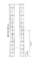
そのため、将来の通信システムでは、TTIを1msより短縮した短縮TTIを利用して通信を行うことが考えられる(図2参照)。図2では、通常TTI(1ms)を利用するセル(CC#1)と、短縮TTIを利用するセル(CC#2)を示している。また、短縮TTIを利用する場合、サブキャリア間隔を通常TTIのサブキャリアから変更(例えば、サブキャリア間隔を拡大)することが考えられる。 Therefore, in future communication systems, it is conceivable to perform communication using a shortened TTI in which the TTI is shortened from 1 ms (see FIG. 2). FIG. 2 shows a cell (CC # 1) that normally uses TTI (1 ms) and a cell (CC # 2) that uses shortened TTI. Further, when the shortened TTI is used, it is conceivable to change the subcarrier interval from the normal TTI subcarrier (for example, increase the subcarrier interval).
通常TTIよりも短い時間長のTTI(以下、「短縮TTI」という)を用いる場合、ユーザ端末や無線基地局における処理(例えば、符号化、復号など)に対する時間的マージンが増加するため、処理遅延を低減できる。また、短縮TTIを用いる場合、単位時間(例えば、1ms)当たりに収容可能なユーザ端末数を増加させることができる。以下に、短縮TTIの構成等について説明する。 When a TTI having a shorter time length than the normal TTI (hereinafter referred to as "shortened TTI") is used, a processing delay occurs because the time margin for processing (for example, coding, decoding, etc.) in the user terminal or wireless base station increases. Can be reduced. Further, when the shortened TTI is used, the number of user terminals that can be accommodated per unit time (for example, 1 ms) can be increased. The configuration of the shortened TTI and the like will be described below.
(短縮TTIの構成例)
短縮TTIの構成例について図3を参照して説明する。図3A及び図3Bに示すように、短縮TTIは、1msより小さい時間長(TTI長)を有する。短縮TTIは、例えば、0.5ms、0.25ms、0.2ms、0.1msなど、倍数が1msとなるTTI長であってもよい。(Structure example of shortened TTI)
A configuration example of the shortened TTI will be described with reference to FIG. As shown in FIGS. 3A and 3B, the shortened TTI has a time length (TTI length) less than 1 ms. The shortened TTI may have a TTI length in which the multiple is 1 ms, for example, 0.5 ms, 0.25 ms, 0.2 ms, 0.1 ms.
なお、図3A及び図3Bでは、通常CPの場合を一例として説明するが、これに限られない。短縮TTIは、通常TTIよりも短い時間長であればよく、短縮TTI内のシンボル数、シンボル長、CP長などの構成はどのようなものであってもよい。また、以下では、DLにOFDMシンボル、ULにSC−FDMAシンボルが用いられる例を説明するが、これらに限られるものではない。 In addition, in FIG. 3A and FIG. 3B, the case of normal CP will be described as an example, but the present invention is not limited to this. The shortened TTI may have a time length shorter than that of the normal TTI, and the shortened TTI may have any configuration such as the number of symbols, the symbol length, and the CP length. Further, an example in which the OFDM symbol is used for DL and the SC-FDMA symbol is used for UL will be described below, but the present invention is not limited thereto.
図3Aは、短縮TTIの第1の構成例を示す図である。図3Aに示すように、第1の構成例では、短縮TTIは、通常TTIと同一数の14OFDMシンボル(又はSC−FDMAシンボル)で構成され、各OFDMシンボル(各SC−FDMAシンボル)は、通常TTIのシンボル長(=66.7μs)よりも短いシンボル長を有する。 FIG. 3A is a diagram showing a first configuration example of the shortened TTI. As shown in FIG. 3A, in the first configuration example, the shortened TTI is composed of the same number of 14 OFDM symbols (or SC-FDMA symbols) as the normal TTI, and each OFDM symbol (each SC-FDMA symbol) is usually. It has a symbol length shorter than the symbol length of TTI (= 66.7 μs).
図3Aに示すように、通常TTIのシンボル数を維持してシンボル長を短くする場合、通常TTIの物理レイヤ信号構成を流用することができる。また、通常TTIのシンボル数を維持してシンボル長を短くする場合、サブキャリア間隔が大きくなるため、短縮TTIに含める情報量(ビット量)を通常TTIよりも削減できる。 As shown in FIG. 3A, when the number of symbols of the normal TTI is maintained and the symbol length is shortened, the physical layer signal configuration of the normal TTI can be diverted. Further, when the number of symbols of the normal TTI is maintained and the symbol length is shortened, the subcarrier interval becomes large, so that the amount of information (bit amount) included in the shortened TTI can be reduced as compared with the normal TTI.
図3Bは、短縮TTIの第2の構成例を示す図である。図3Bに示すように、第2の構成例では、短縮TTIは、通常TTIよりも少ない数のOFDMシンボル(又はSC−FDMAシンボル)で構成され、各OFDMシンボル(各SC−FDMAシンボル)は、通常TTIと同一のシンボル長(=66.7μs)を有する。この場合、短縮TTIは、通常TTIにおけるシンボル単位で構成することができる。例えば、1サブフレームに含まれる14シンボルのうちの一部のシンボルを利用して短縮TTIを構成することができる。図3Bでは、短縮TTIは、通常TTIの半分の7OFDMシンボル(SC−FDMAシンボル)で構成される。 FIG. 3B is a diagram showing a second configuration example of the shortened TTI. As shown in FIG. 3B, in the second configuration example, the shortened TTI is usually composed of a smaller number of OFDM symbols (or SC-FDMA symbols) than the TTI, and each OFDM symbol (each SC-FDMA symbol) is composed of. It usually has the same symbol length (= 66.7 μs) as TTI. In this case, the shortened TTI can usually be configured in symbol units in the TTI. For example, a shortened TTI can be constructed by using some of the 14 symbols included in one subframe. In FIG. 3B, the shortened TTI usually consists of 7 OFDM symbols (SC-FDMA symbols), which are half of the TTI.
図3Bに示すように、シンボル長を維持してシンボル数を削減する場合、短縮TTIに含める情報量(ビット量)を通常TTIよりも削減できる。このため、ユーザ端末は、通常TTIよりも短い時間で、短縮TTIに含まれる情報の受信処理(例えば、復調、復号など)を行うことができ、処理遅延を短縮できる。また、図3Bに示す短縮TTIの信号と通常TTIの信号とを同一CCで多重(例えば、OFDM多重)でき、通常TTIとの互換性を維持できる。 As shown in FIG. 3B, when the number of symbols is reduced while maintaining the symbol length, the amount of information (bit amount) included in the shortened TTI can be reduced as compared with the normal TTI. Therefore, the user terminal can perform reception processing (for example, demodulation, decoding, etc.) of the information included in the shortened TTI in a shorter time than the normal TTI, and the processing delay can be shortened. Further, the shortened TTI signal shown in FIG. 3B and the normal TTI signal can be multiplexed (for example, OFDM multiplexing) with the same CC, and compatibility with the normal TTI can be maintained.
(短縮TTIの設定例)
短縮TTIの設定例について説明する。短縮TTIを適用する場合、既存システム(LTE Rel.8−12)との互換性を有するように、通常TTI及び短縮TTIの双方をユーザ端末に設定する構成とすることも可能である。図4は、通常TTI及び短縮TTIの設定例を示す図である。なお、図4は、例示にすぎず、これらに限られるものではない。(Example of shortened TTI setting)
An example of setting the shortened TTI will be described. When applying the shortened TTI, it is also possible to set both the normal TTI and the shortened TTI on the user terminal so as to have compatibility with the existing system (LTE Rel. 8-12). FIG. 4 is a diagram showing a setting example of normal TTI and shortened TTI. Note that FIG. 4 is merely an example, and the present invention is not limited to these.
図4Aは、短縮TTIの第1の設定例を示す図である。図4Aに示すように、通常TTIと短縮TTIとは、同一のコンポーネントキャリア(CC)(周波数領域)内で時間的に混在してもよい。具体的には、短縮TTIは、同一のCCの特定のサブフレーム(或いは、特定の無線フレーム)に設定されてもよい。例えば、図4Aでは、同一のCC内の連続する5サブフレームにおいて短縮TTIが設定され、その他のサブフレームにおいて通常TTIが設定される。例えば、特定のサブフレームとして、MBSFNサブフレームの設定できるサブフレームや、MIBや同期チャネル等特定の信号を含む(あるいは含まない)サブフレームであってもよい。なお、短縮TTIが設定されるサブフレームの数や位置は、図4Aに示すものに限られない。 FIG. 4A is a diagram showing a first setting example of the shortened TTI. As shown in FIG. 4A, the normal TTI and the shortened TTI may be temporally mixed in the same component carrier (CC) (frequency domain). Specifically, the shortened TTI may be set to a specific subframe (or a specific radio frame) of the same CC. For example, in FIG. 4A, a shortened TTI is set in five consecutive subframes within the same CC, and a normal TTI is set in the other subframes. For example, the specific subframe may be a subframe in which an MBSFN subframe can be set, or a subframe containing (or not including) a specific signal such as a MIB or a synchronization channel. The number and positions of the subframes in which the shortened TTI is set are not limited to those shown in FIG. 4A.
図4Bは、短縮TTIの第2の設定例を示す図である。図4Bに示すように、通常TTIのCCと短縮TTIのCCとを統合して、キャリアアグリゲーション(CA)又はデュアルコネクティビティ(DC)が行われてもよい。具体的には、短縮TTIは、特定のCCに(より具体的には、特定のCCのDL及び/又はULに)、設定されてもよい。例えば、図4Bでは、特定のCCのDLにおいて短縮TTIが設定され、他のCCのDL及びULにおいて通常TTIが設定される。なお、短縮TTIが設定されるCCの数や位置は、図4Bに示すものに限られない。 FIG. 4B is a diagram showing a second setting example of the shortened TTI. As shown in FIG. 4B, carrier aggregation (CA) or dual connectivity (DC) may be performed by integrating the CC of normal TTI and the CC of shortened TTI. Specifically, the shortened TTI may be set to a particular CC (more specifically, to the DL and / or UL of a particular CC). For example, in FIG. 4B, the shortened TTI is set in the DL of a specific CC, and the normal TTI is set in the DL and UL of other CCs. The number and positions of CCs for which the shortened TTI is set are not limited to those shown in FIG. 4B.
また、CAの場合、短縮TTIは、同一の無線基地局の特定のCC(プライマリ(P)セル又は/及びセカンダリ(S)セル)に設定されてもよい。一方、DCの場合、短縮TTIは、第1の無線基地局によって形成されるマスターセルグループ(MCG)内の特定のCC(Pセル又は/及びSセル)に設定されてもよいし、第2の無線基地局によって形成されるセカンダリセルグループ(SCG)内の特定のCC(プライマリセカンダリ(PS)セル又は/及びSセル)に設定されてもよい。 Further, in the case of CA, the shortened TTI may be set to a specific CC (primary (P) cell and / and secondary (S) cell) of the same radio base station. On the other hand, in the case of direct current, the shortened TTI may be set to a specific CC (P cell or / and S cell) in the master cell group (MCG) formed by the first radio base station, or the second. It may be set to a specific CC (primary secondary (PS) cell and / and S cell) in the secondary cell group (SCG) formed by the radio base station of.
図4Cは、短縮TTIの第3の設定例を示す図である。図4Cに示すように、短縮TTIは、DL又はULのいずれかに設定されてもよい。例えば、図4Cでは、TDDシステムにおいて、ULに通常TTIが設定され、DLに短縮TTIが設定される場合を示している。 FIG. 4C is a diagram showing a third setting example of the shortened TTI. As shown in FIG. 4C, the shortened TTI may be set to either DL or UL. For example, FIG. 4C shows a case where the UL is set to the normal TTI and the DL is set to the shortened TTI in the TDD system.
また、DL又はULの特定のチャネルや信号が短縮TTIに割り当てられ(設定され)てもよい。例えば、上り制御チャネル(PUCCH:Physical Uplink Control Channel)は、通常TTIに割り当てられ、上り共有チャネル(PUSCH:Physical Uplink Shared Channel)は、短縮TTIに割り当てられてもよい。 Also, a specific DL or UL channel or signal may be assigned (set) to the shortened TTI. For example, the uplink control channel (PUCCH: Physical Uplink Control Channel) may be normally assigned to the TTI, and the uplink shared channel (PUSCH: Physical Uplink Shared Channel) may be assigned to the shortened TTI.
また、LTE Rel.8−12のマルチアクセス方式であるOFDM(あるいはSC−FDMA)とは異なるマルチアクセス方式が短縮TTIに割り当てられ(設定され)てもよい。 In addition, LTE Rel. A multi-access method different from OFDM (or SC-FDMA), which is a multi-access method of 8-12, may be assigned (set) to the shortened TTI.
以上のように、将来の無線通信では、通常TTIより送信時間間隔が短縮された短縮TTIをUL送信及び/又はDL送信に適用して通信を行うことが想定される。また、将来の無線通信では、上述したように既存システムとの互換性を維持して運用されることが考えられる。この場合、既存システムにおける通常TTI(1サブフレーム)に含まれる14シンボルのうちの一部のシンボルを用いて短縮TTIを構成することが考えられる(図3B参照)。 As described above, in future wireless communication, it is assumed that the shortened TTI, which has a shorter transmission time interval than the normal TTI, is applied to UL transmission and / or DL transmission for communication. Further, in future wireless communication, it is conceivable that the system will be operated while maintaining compatibility with the existing system as described above. In this case, it is conceivable to configure the shortened TTI by using some of the 14 symbols included in the normal TTI (1 subframe) in the existing system (see FIG. 3B).
しかし、かかる場合、短縮TTIをどのように設定し、当該短縮TTIにおいて送信信号及び/又は送信チャネルをどのように配置する(割当てる)かが問題となる。例えば、ユーザ端末が短縮TTIを利用してUL送信を行う場合、短縮TTIの設定やUL信号及び/又はULチャネルの割当てをどのように行うかが問題となる。 However, in such a case, how to set the shortened TTI and how to arrange (assign) the transmission signal and / or the transmission channel in the shortened TTI becomes a problem. For example, when the user terminal uses the shortened TTI to perform UL transmission, the problem is how to set the shortened TTI and allocate the UL signal and / or the UL channel.
そこで、本発明者等は、既存システムの無線フレーム構成との互換性を考慮して、短縮TTIを既存システムのシンボル単位で設定すると共に当該短縮TTIにおける信号及び/又はチャネルの割当てを制御することを着想した。本実施の形態の一態様は、既存システムの1サブフレームを考慮して、既存システムの1サブフレーム内に複数の短縮TTIを設定し、各短縮TTIにおいてUL信号及び/又はULチャネルの割当てを制御する。 Therefore, the present inventors, in consideration of compatibility with the wireless frame configuration of the existing system, set the shortened TTI for each symbol of the existing system and control the allocation of signals and / or channels in the shortened TTI. Was conceived. In one aspect of this embodiment, a plurality of shortened TTIs are set in one subframe of the existing system in consideration of one subframe of the existing system, and the UL signal and / or the UL channel is assigned in each shortened TTI. Control.
また、本実施の形態では、既存システムの1サブフレーム内に複数の短縮TTIを設定し、ユーザ端末がUL信号及び/又はULチャネルを既存システムにおける偶数個のシンボルに割当てるように制御する。例えば、短縮TTIを既存システムにおける偶数個のシンボルで構成する。この場合、上り測定用参照信号等の割当てを考慮して複数の短縮TTIの設定や上り制御チャネルの割当て等を制御することができる。ユーザ端末が既存システムにおける偶数個のシンボルを用いてUL信号及び/又はULチャネルの割当てを制御する場合、周波数ホッピングにより異なる周波数領域に割当てられるUL信号及び/又はULチャネルのシンボル数を等しくすることができる。 Further, in the present embodiment, a plurality of shortened TTIs are set in one subframe of the existing system, and the user terminal is controlled to allocate the UL signal and / or the UL channel to an even number of symbols in the existing system. For example, the shortened TTI consists of an even number of symbols in the existing system. In this case, it is possible to control the setting of a plurality of shortened TTIs, the allocation of the uplink control channel, and the like in consideration of the allocation of the uplink measurement reference signal and the like. When the user terminal controls the allocation of UL signals and / or UL channels using an even number of symbols in an existing system, the number of symbols of UL signals and / or UL channels allocated to different frequency domains by frequency hopping should be equalized. Can be done.
このように、既存システムの無線フレーム構成を考慮して短縮TTIを設定すると共にUL信号及び/又はULチャネルを割当てるシンボル数(又は、1TTIのシンボル数)を制御することにより、短縮TTIを適用する場合であっても既存システムとの互換性を維持して通信を適切に行うことができる。 In this way, the shortened TTI is applied by setting the shortened TTI in consideration of the radio frame configuration of the existing system and controlling the number of symbols (or the number of symbols of 1 TTI) to which the UL signal and / or the UL channel is allocated. Even in this case, compatibility with the existing system can be maintained and communication can be performed appropriately.
以下に本実施の形態について詳細に説明する。以下の説明では、通常TTI(1ms)より短い時間長の伝送単位を短縮TTIと呼ぶが、「短縮TTI」という名称はこれに限られない。また、以下の説明ではLTEシステムを例に挙げるが本実施の形態はこれに限られず、短縮TTIを利用するシステムであれば適用することができる。 The present embodiment will be described in detail below. In the following description, a transmission unit having a time length shorter than that of TTI (1 ms) is usually referred to as a shortened TTI, but the name "shortened TTI" is not limited to this. Further, in the following description, the LTE system will be taken as an example, but the present embodiment is not limited to this, and any system using the shortened TTI can be applied.
(第1の態様)
第1の態様では、短縮TTIにおけるUL信号及び/又はULチャネルの割当て(マッピング)方法について説明する。なお、以下の説明では、上り制御チャネル(例えば、PUCCH)と上り測定用参照信号(例えば、SRS)を例に挙げてUL送信の割当ての一例を示すがこれに限られない。例えば、上り制御チャネルが割当てられる領域に隣接するシンボル及び/又はサブキャリアに復調用の参照信号を割当てることができる。また、上り制御チャネルが割当てられない領域にユーザデータ(例えば、PUSCH)を割当てることができる。(First aspect)
In the first aspect, the UL signal and / or UL channel allocation (mapping) method in the shortened TTI will be described. In the following description, an example of UL transmission allocation is shown by taking an uplink control channel (for example, PUCCH) and an uplink measurement reference signal (for example, SRS) as an example, but the present invention is not limited to this. For example, a reference signal for demodulation can be assigned to a symbol and / or a subcarrier adjacent to the area to which the uplink control channel is assigned. Further, user data (for example, PUSCH) can be allocated to an area to which the uplink control channel is not allocated.
<1TTIを1スロットで構成>
図5は、短縮TTIを既存システムのサブフレームにおける1スロットで構成する場合(1TTI=1スロット)のUL信号とULチャネルの割当て方法の一例を示している。この場合、既存システムの1サブフレームにおいて、1番目のスロットに対応する短縮TTIと、2番目のスロットに対応する短縮TTIの2つの短縮TTIが設定される。<1 TTI consists of 1 slot>
FIG. 5 shows an example of a method of allocating UL signals and UL channels when the shortened TTI is configured by one slot in a subframe of an existing system (1 TTI = 1 slot). In this case, two shortened TTIs, a shortened TTI corresponding to the first slot and a shortened TTI corresponding to the second slot, are set in one subframe of the existing system.
ユーザ端末は、各短縮TTIにUL信号及び/又はULチャネルの割当てを行う。例えば、ユーザ端末は、各短縮TTIにおいて上り制御チャネル(例えば、PUCCH)に周波数ホッピングを適用して割当てを制御する。これにより、短縮TTIを利用する場合であっても周波数ダイバーシチ効果を得ることができる。 The user terminal assigns a UL signal and / or a UL channel to each shortened TTI. For example, the user terminal applies frequency hopping to the uplink control channel (eg, PUCCH) in each shortened TTI to control allocation. As a result, the frequency diversity effect can be obtained even when the shortened TTI is used.
図5に示す場合、1番目のスロットに対応する短縮TTIにおいて上り制御チャネルが割当て可能な領域は7シンボルとなる。この場合、ユーザ端末は、周波数ホッピングにより異なる周波数領域に割当てられる上り制御チャネルのシンボル数が異なるように割当てを制御することができる。 In the case shown in FIG. 5, the area to which the uplink control channel can be allocated in the shortened TTI corresponding to the first slot is 7 symbols. In this case, the user terminal can control the allocation so that the number of symbols of the uplink control channel allocated to different frequency domains by frequency hopping is different.
2番目のスロットに対応する短縮TTIも7シンボルで構成される。一方で、既存システムでは、サブフレーム(2番目のスロット)の最終シンボルに上り測定用の参照信号(例えば、SRS:Sounding Reference Signal(Symbol))が設定される。かかる場合、ユーザ端末は、上り制御チャネルと上り測定用参照信号の衝突を避けるため、最終シンボルに上り制御チャネルを割当てないように制御することが好ましい。 The shortened TTI corresponding to the second slot is also composed of 7 symbols. On the other hand, in the existing system, a reference signal for uplink measurement (for example, SRS: Sounding Reference Signal (Symbol)) is set as the final symbol of the subframe (second slot). In such a case, it is preferable that the user terminal controls so that the uplink control channel is not assigned to the final symbol in order to avoid collision between the uplink control channel and the uplink measurement reference signal.
そのため、ユーザ端末は、2番目のスロットに対応する短縮TTIでは、上り測定用参照信号が割当てられるシンボルを除いた6シンボル(シンボル#0−#5)に上り制御チャネルを割当てるように制御する。この場合、ユーザ端末は、周波数ホッピングにより異なる周波数領域に割当てられる上り制御チャネルのシンボル数が同一(ここでは、3シンボル)となるように割当てを制御することができる。 Therefore, in the shortened TTI corresponding to the second slot, the user terminal controls to allocate the uplink control channel to 6 symbols (symbols # 0- # 5) excluding the symbol to which the uplink measurement reference signal is assigned. In this case, the user terminal can control the allocation so that the number of symbols of the uplink control channels allocated to different frequency domains by frequency hopping is the same (here, 3 symbols).
このように、短縮TTIが既存システムの1サブフレームにおける1スロットで構成される場合、ユーザ端末は、1番目のスロットに対応する短縮TTIと2番目のスロットに対応する短縮TTIに対して、異なるマッピング方法を用いてUL信号及び/又はULチャネルの割当てを制御することができる。これにより、既存システムで規定されている上り測定用の参照信号の割当てを考慮すると共に、無線リソースの利用効率を向上することができる。 In this way, when the shortened TTI is composed of one slot in one subframe of the existing system, the user terminal is different from the shortened TTI corresponding to the first slot and the shortened TTI corresponding to the second slot. The mapping method can be used to control the allocation of UL signals and / or UL channels. As a result, it is possible to consider the allocation of the reference signal for uplink measurement specified in the existing system and improve the utilization efficiency of the radio resource.
また、ユーザ端末は、短縮TTIに割当てる上り制御チャネルと既存システム(通常TTI)に割当てる上り制御チャネルを多重するように割当てを制御することができる。この場合、短縮TTIに割当てる上り制御チャネルのリソースが既存システムの上り制御チャネルのリソースと衝突しない(直交する)ように多重(例えば、周波数分割多重及び/又は符号分割多重)を制御する。 Further, the user terminal can control the allocation so as to multiplex the uplink control channel assigned to the shortened TTI and the uplink control channel assigned to the existing system (usually TTI). In this case, multiplexing (for example, frequency division multiplexing and / or code division multiplexing) is controlled so that the uplink control channel resources allocated to the shortened TTI do not collide (orthogonally) with the uplink control channel resources of the existing system.
また、ユーザ端末は、2番目のスロットに対応するTTI内に上り測定用参照信号を割当てることができるが、SRSが送信されない場合には、1番目のスロットに対応する短縮TTIと同様に最終シンボルに上り制御チャネルを割当ててもよい。 Further, the user terminal can assign the reference signal for uplink measurement in the TTI corresponding to the second slot, but when the SRS is not transmitted, the final symbol is the same as the shortened TTI corresponding to the first slot. An uplink control channel may be assigned to.
また、ユーザ端末は、1番目のスロットの7番目のシンボル(#6)に上り制御チャネルを割当てないように制御してもよい。これにより、TTIが既存システムの1スロット(7個のシンボル)で構成される場合であっても、周波数ホッピングにより異なる周波数領域に割当てられる上り制御チャネルのシンボル数を同一とすることができる。 Further, the user terminal may control so that the uplink control channel is not assigned to the seventh symbol (# 6) of the first slot. As a result, even when the TTI is composed of one slot (7 symbols) of the existing system, the number of symbols of the uplink control channel assigned to different frequency domains by frequency hopping can be the same.
<1TTIを偶数シンボルで構成>
また、本実施の形態では、既存システムのシンボルを偶数個用いて短縮TTIを構成することができる。この場合、ユーザ端末は、既存システムにおける偶数個のシンボルで構成される短縮TTIを利用してUL信号及び/又はULチャネルの割当てを制御する。短縮TTIを構成するシンボル数を偶数個とすることにより、周波数ホッピングにより周波数方向に分散されるULチャネル(例えば、上り制御チャネル)のシンボル数を等しくすることができる。短縮TTIを構成する偶数個のシンボルとしては、6個、4個又は2個とすることができる。なお、シンボル数が異なる短縮TTIを組み合わせて利用することも可能である。<1 TTI composed of even symbols>
Further, in the present embodiment, the shortened TTI can be configured by using an even number of symbols of the existing system. In this case, the user terminal controls the allocation of the UL signal and / or the UL channel by utilizing the shortened TTI composed of an even number of symbols in the existing system. By setting the number of symbols constituting the shortened TTI to an even number, the number of symbols of the UL channel (for example, the uplink control channel) distributed in the frequency direction by frequency hopping can be made equal. The even number of symbols constituting the abbreviated TTI may be 6, 4, or 2. It is also possible to use a combination of shortened TTIs having different numbers of symbols.
・短縮TTIのシンボル数が6個の場合
図6は、短縮TTIを既存システムの6個のシンボルで構成する場合(1TTI=6シンボル)のUL信号とULチャネルの割当て方法の一例を示している。この場合、既存システムの1サブフレームにおいて、2個の短縮TTIを設定することができる。-When the number of symbols of the shortened TTI is six FIG. 6 shows an example of the UL signal and UL channel allocation method when the shortened TTI is composed of six symbols of the existing system (1 TTI = 6 symbols). .. In this case, two shortened TTIs can be set in one subframe of the existing system.
図6では、1番目のスロットの2番目のシンボル(#1)から7番目のシンボル(#6)までの6個のシンボルに対応する短縮TTIと、2番目のスロットの1番目のシンボル(#0)から6番目のシンボル(#5)までの6個のシンボルに対応する短縮TTIが設定される場合を示している。 In FIG. 6, the shortened TTI corresponding to the six symbols from the second symbol (# 1) to the seventh symbol (# 6) in the first slot and the first symbol (#) in the second slot. It shows the case where the shortened TTI corresponding to 6 symbols from 0) to the 6th symbol (# 5) is set.
ユーザ端末は、各短縮TTIにUL信号及び/又はULチャネルの割当てを行う。例えば、ユーザ端末は、各短縮TTIにおいて上り制御チャネル(例えば、PUCCH)に周波数ホッピングを適用して割当てを制御する。 The user terminal assigns a UL signal and / or a UL channel to each shortened TTI. For example, the user terminal applies frequency hopping to the uplink control channel (eg, PUCCH) in each shortened TTI to control allocation.
図6に示す場合、各短縮TTIにおいて上り制御チャネルが割当て可能な領域は6個のシンボル(偶数)となる。このため、ユーザ端末は、周波数ホッピングにより異なる周波数領域に割当てられる上り制御チャネルのシンボル数が等しくなる(ここでは、3個)ように割当てを制御することができる。このように、異なる周波数領域に対して上り制御チャネルが対照配置となるように周波数ホッピングを適用することにより割当ての制御を簡略化すると共に、短縮TTIを利用する場合であっても周波数ダイバーシチ効果を得ることができる。 In the case shown in FIG. 6, the area to which the uplink control channel can be assigned in each shortened TTI is 6 symbols (even numbers). Therefore, the user terminal can control the allocation so that the number of symbols of the uplink control channels allocated to different frequency domains by frequency hopping is equal (here, three). In this way, frequency hopping is applied so that the uplink control channels are arranged in a control manner for different frequency domains, thereby simplifying the control of allocation and achieving the frequency diversity effect even when the shortened TTI is used. Obtainable.
また、短縮TTIは、既存システムの1サブフレームにおいて、先頭シンボル(1番目のスロットのシンボル#0)及び/又は最終シンボル(2番目のスロットのシンボル#6)を含まないように構成することができる。短縮TTIに最終シンボルを含めない場合、ユーザ端末は、既存システムの1サブフレームで上り測定用参照信号が割当てられるシンボル(最終シンボル)を短縮TTIのシンボルとして利用せずにUL信号及び/又はULチャネルの割当てを制御することができる。
Further, the shortened TTI may be configured so as not to include the first symbol (
これにより、上り測定用参照信号と、短縮TTIに割当てられる上り制御チャネルの衝突を回避することができる。また、ユーザ端末は、上り測定用参照信号の割当ての有無に関わらず、所定のPUCCHフォーマット(非短縮PUCCHフォーマット)を利用して上り制御チャネルの割当てを行うことができる。 As a result, it is possible to avoid a collision between the uplink measurement reference signal and the uplink control channel assigned to the shortened TTI. Further, the user terminal can allocate the uplink control channel by using a predetermined PUCCH format (non-shortened PUCCH format) regardless of whether or not the uplink measurement reference signal is allocated.
また、短縮TTIに先頭シンボルを含めない場合、ユーザ端末は、先頭シンボル(1番目のスロットのシンボル#0)を短縮TTIのシンボルとして利用せずにUL信号及び/又はULチャネルの割当てを制御することができる。先頭シンボルを空ける(利用しない)構成とすることにより、ユーザ端末におけるタイミングアドバンス(Timing advance)制御の条件が緩和され、タイミングアドバンス制御を適用しやすくなる。
Further, when the leading symbol is not included in the shortened TTI, the user terminal controls the allocation of the UL signal and / or the UL channel without using the leading symbol (
タイミングアドバンス制御は、無線基地局において複数のユーザ端末から送信されるUL信号の受信タイミングが一致するように、各ユーザ端末から送信されるUL送信のタイミングを制御する動作を指す。つまり、無線基地局から距離が遠いユーザ端末は、他のユーザ端末より早めにUL送信を開始するように制御する。この場合、図6に示すように先頭シンボルを空けることにより、ユーザ端末は、先頭シンボルからUL送信を行う場合と比較して、UL送信のタイミング制御(早めのUL送信開始)を容易に行うことができる。 The timing advance control refers to an operation of controlling the timing of UL transmission transmitted from each user terminal so that the reception timings of UL signals transmitted from a plurality of user terminals match in the radio base station. That is, the user terminal far from the radio base station is controlled to start the UL transmission earlier than the other user terminals. In this case, by leaving the first symbol as shown in FIG. 6, the user terminal can easily perform UL transmission timing control (early start of UL transmission) as compared with the case where UL transmission is performed from the first symbol. Can be done.
また、ユーザ端末は、短縮TTIに割当てる上り制御チャネルと既存システム(通常TTI)に割当てる上り制御チャネルを多重するように割当てを制御することができる。この場合、短縮TTIに割当てる上り制御チャネルのリソースが既存システムの上り制御チャネルのリソースと衝突しないように多重(例えば、周波数分割多重及び/又は符号分割多重)を制御する。 Further, the user terminal can control the allocation so as to multiplex the uplink control channel assigned to the shortened TTI and the uplink control channel assigned to the existing system (usually TTI). In this case, multiplexing (for example, frequency division multiplexing and / or code division multiplexing) is controlled so that the uplink control channel resources allocated to the shortened TTI do not collide with the uplink control channel resources of the existing system.
また、ユーザ端末は、短縮TTIが設定されない先頭シンボルに対して、ULデータ(例えば、PUSCH)やUL制御情報(例えば、PUCCH)以外の他の信号(例えば、参照信号、PRACH等)を割当てる構成としてもよい。 Further, the user terminal is configured to allocate other signals (for example, reference signal, PRACH, etc.) other than UL data (for example, PUSCH) and UL control information (for example, PUCCH) to the first symbol for which the shortened TTI is not set. May be.
・短縮TTIのシンボル数が4個の場合
図7は、短縮TTIを既存システムの4個のシンボルで構成する場合(1TTI=4シンボル)のUL信号とULチャネルの割当て方法の一例を示している。この場合、既存システムの1サブフレームにおいて、3個の短縮TTIを設定することができる。つまり、図6の場合と比較して低遅延化の効果を大きくすることができる。-When the number of symbols of the shortened TTI is four FIG. 7 shows an example of the UL signal and UL channel allocation method when the shortened TTI is composed of four symbols of the existing system (1 TTI = 4 symbols). .. In this case, three shortened TTIs can be set in one subframe of the existing system. That is, the effect of reducing the delay can be increased as compared with the case of FIG.
図7では、1番目のスロットの2番目のシンボル(#1)から5番目のシンボル(#4)までの4個のシンボルに対応する短縮TTIと、1番目のスロットの6番目のシンボル(#5)から2番目のスロットの2番目のシンボル(#1)までの4個のシンボルに対応する短縮TTIと、2番目のスロットの3番目のシンボル(#2)から2番目のスロットの6番目のシンボル(#5)までの4個のシンボルに対応する短縮TTIが設定される場合を示している。 In FIG. 7, the shortened TTI corresponding to the four symbols from the second symbol (# 1) to the fifth symbol (# 4) in the first slot and the sixth symbol (#) in the first slot. The shortened TTI corresponding to the four symbols from 5) to the second symbol (# 1) in the second slot, and the sixth in the second slot from the third symbol (# 2) in the second slot. It shows the case where the shortened TTI corresponding to the four symbols up to the symbol (# 5) of is set.
ユーザ端末は、各短縮TTIにおいて上り制御チャネル(例えば、PUCCH)に周波数ホッピングを適用して割当てを制御することができる。図7に示す場合、各短縮TTIにおいて上り制御チャネルが割当て可能な領域は4個のシンボル(偶数)となる。このため、ユーザ端末は、周波数ホッピングにより異なる周波数領域に割当てられる上り制御チャネルのシンボル数が等しくなる(ここでは、2個)ように割当てを制御することができる。このように、異なる周波数領域に対して上り制御チャネルが対照配置となるように周波数ホッピングを適用することにより割当ての制御を簡略化すると共に、短縮TTIを利用する場合であっても周波数ダイバーシチ効果を得ることができる。 The user terminal can control the allocation by applying frequency hopping to the uplink control channel (for example, PUCCH) in each shortened TTI. In the case shown in FIG. 7, the area to which the uplink control channel can be assigned in each shortened TTI is four symbols (even numbers). Therefore, the user terminal can control the allocation so that the number of symbols of the uplink control channels allocated to different frequency domains by frequency hopping is equal (here, two). In this way, frequency hopping is applied so that the uplink control channels are arranged in a control manner for different frequency domains, thereby simplifying the control of allocation and achieving the frequency diversity effect even when the shortened TTI is used. Obtainable.
また、短縮TTIは、既存システムの1サブフレームにおいて、先頭シンボル(1番目のスロットのシンボル#0)及び/又は最終シンボル(2番目のスロットのシンボル#6)を含まないように構成することができる。
Further, the shortened TTI may be configured so as not to include the first symbol (
短縮TTIに最終シンボルを含めない場合、ユーザ端末は、既存システムの1サブフレームで上り測定用参照信号が割当てられるシンボル(最終シンボル)を短縮TTIのシンボルとして利用せずにUL信号及び/又はULチャネルの割当てを制御することができる。 If the abbreviated TTI does not include the final symbol, the user terminal does not use the symbol (final symbol) to which the uplink measurement reference signal is assigned in one subframe of the existing system as the abbreviated TTI symbol, and the UL signal and / or UL. You can control the allocation of channels.
また、短縮TTIに先頭シンボルを含めない場合、ユーザ端末は、先頭シンボル(1番目のスロットのシンボル#0)を短縮TTIのシンボルとして利用せずにUL信号及び/又はULチャネルの割当てを制御することができる。先頭シンボルを空ける(利用しない)構成とすることにより、ユーザ端末におけるタイミングアドバンス(Timing advance)制御の条件が緩和され、タイミングアドバンス制御を適用しやすくなる。
Further, when the leading symbol is not included in the shortened TTI, the user terminal controls the allocation of the UL signal and / or the UL channel without using the leading symbol (
また、ユーザ端末は、上り制御チャネルを復調するために利用する参照信号(DM−RS)を、上り制御チャネルが割当てらえる領域(リソースエレメント)と時間方向及び/又は周波数方向において隣接する領域(例えば、隣のリソースエレメント)に割当てることができる。 Further, the user terminal allocates the reference signal (DM-RS) used for demodulating the uplink control channel to the region (resource element) to which the uplink control channel is assigned, and the region adjacent to the region (resource element) in the time direction and / or the frequency direction ( For example, it can be assigned to the adjacent resource element).
例えば、図7に示す場合、ユーザ端末は、上り制御チャネルが割当てられるシンボル(例えば、1番目のスロットのシンボル#1)に隣接するシンボル(例えば、1番目のスロットのシンボル#2)に復調用の参照信号を割当てることができる。同様に、ユーザ端末は、1番目のスロットのシンボル#3に上り制御チャネルを割当て、隣接するシンボル(例えば、1番目のスロットのシンボル#4)に復調用の参照信号を割当てることができる。
For example, in the case shown in FIG. 7, the user terminal demodulates to a symbol (for example,
あるいは、ユーザ端末は、同じシンボル(例えば、1番目のスロットのシンボル#1)の異なるサブキャリアに上り制御チャネルと復調用の参照信号を割当てる(周波数分割多重する)ことも可能である。この場合、連続する2つのシンボル(例えば、1番目のスロットのシンボル#1と#2)に対して、上り制御チャネルと復調用参照信号を割当てることができる。
Alternatively, the user terminal can assign an uplink control channel and a reference signal for demodulation (frequency division multiplexing) to different subcarriers of the same symbol (for example,
・短縮TTIのシンボル数が2個の場合
図8は、短縮TTIを既存システムの2個のシンボルで構成する場合(1TTI=2シンボル)のUL信号とULチャネルの割当て方法の一例を示している。この場合、既存システムの1サブフレームにおいて、6個の短縮TTIを設定することができる。つまり、図6、図7の場合と比較して低遅延化の効果を大きくすることができる。-When the number of symbols of the shortened TTI is two FIG. 8 shows an example of the UL signal and UL channel allocation method when the shortened TTI is composed of two symbols of the existing system (1 TTI = 2 symbols). .. In this case, six shortened TTIs can be set in one subframe of the existing system. That is, the effect of reducing the delay can be increased as compared with the cases of FIGS. 6 and 7.
図8では、1番目のスロットの2番目のシンボル(#1)から2番目のスロットの6番目のシンボル(#5)までの領域に、それぞれ2個のシンボルで構成される複数の短縮TTIが設定される場合を示している。 In FIG. 8, in the area from the second symbol (# 1) in the first slot to the sixth symbol (# 5) in the second slot, a plurality of shortened TTIs each consisting of two symbols are formed. Indicates the case where it is set.
ユーザ端末は、各短縮TTIにおいて上り制御チャネル(例えば、PUCCH)に周波数ホッピングを適用して割当てを制御することができる。図8に示す場合、各短縮TTIにおいて上り制御チャネルが割当て可能な領域は2個のシンボル(偶数)となる。このため、ユーザ端末は、周波数ホッピングにより異なる周波数領域に割当てられる上り制御チャネルのシンボル数が等しくなる(ここでは、1個)ように割当てを制御することができる。このように、異なる周波数領域に対して上り制御チャネルが対照配置となるように周波数ホッピングを適用することにより割当ての制御を簡略化すると共に、短縮TTIを利用する場合であっても周波数ダイバーシチ効果を得ることができる。 The user terminal can control the allocation by applying frequency hopping to the uplink control channel (for example, PUCCH) in each shortened TTI. In the case shown in FIG. 8, the area to which the uplink control channel can be assigned in each shortened TTI is two symbols (even numbers). Therefore, the user terminal can control the allocation so that the number of symbols of the uplink control channels allocated to different frequency domains by frequency hopping is equal (here, one). In this way, frequency hopping is applied so that the uplink control channels are arranged in a control manner for different frequency domains, thereby simplifying the control of allocation and achieving the frequency diversity effect even when the shortened TTI is used. Obtainable.
また、短縮TTIは、既存システムの1サブフレームにおいて、先頭シンボル(1番目のスロットのシンボル#0)及び/又は最終シンボル(2番目のスロットのシンボル#6)を含まないように構成することができる。
Further, the shortened TTI may be configured so as not to include the first symbol (
また、ユーザ端末は、上り制御チャネルを復調するために利用する参照信号(DM−RS)を、上り制御チャネルが割当てられる領域(シンボル)に割当てることができる。例えば、図8に示す場合、ユーザ端末は、同じシンボル(例えば、1番目のスロットのシンボル#1)の異なるサブキャリアに上り制御チャネルと復調用の参照信号を割当てる(周波数分割多重する)ことができる。
Further, the user terminal can allocate the reference signal (DM-RS) used for demodulating the uplink control channel to the area (symbol) to which the uplink control channel is allocated. For example, in the case shown in FIG. 8, the user terminal may assign an uplink control channel and a reference signal for demodulation (frequency division multiplexing) to different subcarriers of the same symbol (for example,
(第2の態様)
第2の態様では、短縮TTIを利用した場合に、DL送信に対するHARQ−ACK(ACK/NACK)フィードバック制御について説明する。以下の説明では、UL送信用の短縮TTIを既存システムにおける4個のシンボルで構成する場合(図7参照)を示すが、本実施の形態はこれに限られない。他の構成(例えば、短縮TTIが2個、6、7個で構成される場合)についても同様に適用することができる。また、以下の説明ではFDDにおいて短縮TTIを利用する場合のHARQ−ACK制御を示すが、本実施の形態はFDDだけでなくTDDに対しても適用することができる。(Second aspect)
In the second aspect, HARQ-ACK (ACK / NACK) feedback control for DL transmission will be described when the shortened TTI is used. In the following description, a case where the shortened TTI for UL transmission is composed of four symbols in the existing system (see FIG. 7) is shown, but the present embodiment is not limited to this. The same can be applied to other configurations (for example, when the shortened TTI is composed of 2, 6, and 7). Further, although the following description shows HARQ-ACK control when shortened TTI is used in FDD, the present embodiment can be applied not only to FDD but also to TDD.
図9は、DL送信に対するHARQ−ACK(DL HARQ)制御の一例を示している。ユーザ端末は、DL信号を受信してから所定期間後のUL送信用の短縮TTIを利用して、DL送信に対するACK/NACKをフィードバックする。 FIG. 9 shows an example of HARQ-ACK (DL HARQ) control for DL transmission. The user terminal feeds back ACK / NACK for DL transmission by using the shortened TTI for UL transmission after a predetermined period after receiving the DL signal.
例えば、ユーザ端末は、DLを受信したTTI(例えば、短縮TTI)が含まれる既存システムのサブフレーム(n)から所定後のサブフレームに含まれる短縮TTIを利用してACK/NACKフィードバックを制御することができる。このように、ユーザ端末は、既存システムのサブフレーム単位でACK/NACKフィードバックタイミングを制御することができる。図9では、サブフレーム(n)に含まれる短縮TTIで受信したDL信号のACK/NACKを所定期間(例えば、2ms)後のサブフレーム(n+2)に含まれる短縮TTIで送信する場合を示している。 For example, the user terminal controls ACK / NACK feedback from the subframe (n) of the existing system including the TTI that received the DL (for example, the shortened TTI) by using the shortened TTI included in the subframe after the predetermined period. be able to. In this way, the user terminal can control the ACK / NACK feedback timing in units of subframes of the existing system. FIG. 9 shows a case where the ACK / NACK of the DL signal received in the shortened TTI included in the subframe (n) is transmitted in the shortened TTI included in the subframe (n + 2) after a predetermined period (for example, 2 ms). There is.
なお、ユーザ端末がACK/NACKをフィードバックするタイミングは2msに限られず、1ms後のサブフレーム(n+1)に含まれる短縮TTIで送信してもよい(図10参照)。あるいは、ユーザ端末は、既存システムのサブフレーム単位でなく、短縮TTIを単位としてACK/NACKフィードバックタイミングを制御することができる。図9に示す場合、ユーザ端末は、DL信号を受信した短縮TTIから6TTI後のUL送信用のTTIでACK/NACKをフィードバックする。なお、ACK/NACKフィードバックタイミングは、既存サブフレームに含まれる短縮TTI及び/又は短縮TTIを構成するシンボル数に基づいて(関連付けて)決定してもよい。 The timing at which the user terminal feeds back ACK / NACK is not limited to 2 ms, and may be transmitted by a shortened TTI included in the subframe (n + 1) after 1 ms (see FIG. 10). Alternatively, the user terminal can control the ACK / NACK feedback timing in units of shortened TTI instead of in units of subframes of the existing system. In the case shown in FIG. 9, the user terminal feeds back ACK / NACK with the TTI for UL transmission after 6 TTIs from the shortened TTI that received the DL signal. The ACK / NACK feedback timing may be determined based on (associate) with the number of symbols constituting the shortened TTI and / or the shortened TTI included in the existing subframe.
また、既存システムの1サブフレームに含まれるTTIの数がDLとULで同じ場合、ユーザ端末は、1サブフレームに含まれる各DL送信用の短縮TTIでそれぞれ送信されるDL信号のACK/NACKを、所定期間後のサブフレームに含まれるUL送信用の短縮TTIを利用してフィードバックする。図9に示す場合、ユーザ端末は、各サブフレームに含まれるDL送信用の短縮TTI#1で送信されるDL信号に対するACK/NACKを、所定期間後のサブフレームに含まれるUL送信用の短縮TTI#1でフィードバックする。
Further, when the number of TTIs included in one subframe of the existing system is the same for DL and UL, the user terminal ACK / NACK the DL signal transmitted by the shortened TTI for each DL transmission included in one subframe. Is fed back using the shortened TTI for UL transmission included in the subframe after a predetermined period. In the case shown in FIG. 9, the user terminal sets the ACK / NACK for the DL signal transmitted by the shortened
なお、DL送信用の短縮TTIとUL送信用の短縮TTIは、同じシンボル数で構成してもよいし、異なるシンボル数で構成してもよい。また、DL(例えば、DLデータ)送信用の短縮TTIと、UL(例えば、ULデータ)送信用の短縮TTIを時間多重して設定する場合、既存システムの1サブフレーム内にDL送信用の短縮TTIとUL送信用の短縮TTIを設定することも可能である。 The shortened TTI for DL transmission and the shortened TTI for UL transmission may be configured with the same number of symbols or may be configured with different numbers of symbols. Further, when the shortened TTI for DL (for example, DL data) transmission and the shortened TTI for UL (for example, UL data) transmission are set by time multiplexing, the shortened TTI for DL transmission is set within one subframe of the existing system. It is also possible to set a shortened TTI for TTI and UL transmission.
また、無線基地局は、ユーザ端末から送信されたACK/NACKに基づいて、短縮TTIを用いてDL信号の再送を制御することができる。例えば、無線基地局は、ユーザ端末からフィードバックされたACK/NACKを受信してから所定期間(例えば、2サブフレーム、又は6短縮TTI)後のDL送信用のTTIで再送を行うことができる(図11参照)。 Further, the radio base station can control the retransmission of the DL signal by using the shortened TTI based on the ACK / NACK transmitted from the user terminal. For example, the radio base station can retransmit the DL transmission TTI after a predetermined period (for example, 2 subframes or 6 shortened TTIs) after receiving the ACK / NACK fed back from the user terminal (for example, 2 subframes or 6 shortened TTIs). (See FIG. 11).
無線基地局及び/又はユーザ端末は信号の送受信に対して所定のHARQ RTT(Round Trip Time)に基づいて再送制御を行っているが、図11に示す場合、RTTを既存システムの8msから4msに短縮することができる。なお、RTTとは、通信相手に信号やデータを送信してから応答が返ってくるまでにかかる時間を指す。 The radio base station and / or the user terminal perform retransmission control for signal transmission / reception based on a predetermined HARQ RTT (Round Trip Time). In the case shown in FIG. 11, the RTT is changed from 8 ms to 4 ms in the existing system. Can be shortened. The RTT refers to the time required from the transmission of a signal or data to the communication partner until the response is returned.
このように短縮TTIを利用することにより、再送制御に要する時間を短縮することができる。また、短縮TTIを利用する場合、無線基地局とユーザ端末は、既存システムと異なるHARQプロセス数(HPN:HARQ Process Number)を設定してHARQ−ACKを制御することができる。ここで、HARQプロセス数(HARQプロセス番号)は、1つのトランスポートブロック(TB:Transport Block)に対するHARQ処理(HARQプロセス)に対する番号を示す。 By using the shortened TTI in this way, the time required for retransmission control can be shortened. Further, when the shortened TTI is used, the radio base station and the user terminal can control HARQ-ACK by setting a HARQ process number (HPN: HARQ Process Number) different from that of the existing system. Here, the number of HARQ processes (HARQ process number) indicates a number for HARQ processing (HARQ process) for one transport block (TB: Transport Block).
既存システムでは、FDDを適用する際に最大8個のHARQプロセス番号が指定され、それぞれのHARQ処理を並列に動作させることができる。一方で、図11に示すようにFDDで短縮TTIを利用する場合、HARQプロセス数を12(例えば、1サブフレームに含まれる短縮TTI数×RTT)に設定することができる。 In the existing system, a maximum of eight HARQ process numbers are specified when applying FDD, and each HARQ process can be operated in parallel. On the other hand, when the shortened TTI is used in FDD as shown in FIG. 11, the number of HARQ processes can be set to 12 (for example, the number of shortened TTIs included in one subframe × RTT).
短縮TTIを利用する場合のHARQプロセス数は、既存システムの1サブフレームに含まれる短縮TTI及び/又は短縮TTIを利用した場合のRTTに基づいて決定することができる。これにより、短縮TTIを利用する場合であっても、適切なHARQプロセス数を設定して通信を行うことが可能となる。なお、TDDを利用する場合には、さらにUL/DL構成に基づいてHARQプロセス数を設定することができる。 The number of HARQ processes when using the shortened TTI can be determined based on the shortened TTI and / or the RTT when using the shortened TTI included in one subframe of the existing system. As a result, even when the shortened TTI is used, it is possible to set an appropriate number of HARQ processes and perform communication. When using TDD, the number of HARQ processes can be further set based on the UL / DL configuration.
(無線通信システム)
以下、本発明の一実施形態に係る無線通信システムの構成について説明する。この無線通信システムでは、上記各態様に係る無線通信方法が適用される。なお、上記各態様に係る無線通信方法は、それぞれ単独で適用されてもよいし、組み合わせて適用されてもよい。(Wireless communication system)
Hereinafter, the configuration of the wireless communication system according to the embodiment of the present invention will be described. In this wireless communication system, the wireless communication method according to each of the above aspects is applied. The wireless communication methods according to each of the above aspects may be applied individually or in combination.
図12は、本発明の一実施形態に係る無線通信システムの概略構成の一例を示す図である。無線通信システム1では、LTEシステムのシステム帯域幅(例えば、20MHz)を1単位とする複数の基本周波数ブロック(コンポーネントキャリア)を一体としたキャリアアグリゲーション(CA)及び/又はデュアルコネクティビティ(DC)を適用することができる。なお、無線通信システム1は、SUPER 3G、LTE−A(LTE−Advanced)、IMT−Advanced、4G、5G、FRA(Future Radio Access)などと呼ばれても良い。
FIG. 12 is a diagram showing an example of a schematic configuration of a wireless communication system according to an embodiment of the present invention. In the
図12に示す無線通信システム1は、マクロセルC1を形成する無線基地局11と、マクロセルC1内に配置され、マクロセルC1よりも狭いスモールセルC2を形成する無線基地局12a〜12cとを備えている。また、マクロセルC1及び各スモールセルC2には、ユーザ端末20が配置されている。
The
ユーザ端末20は、無線基地局11及び無線基地局12の双方に接続することができる。ユーザ端末20は、異なる周波数を用いるマクロセルC1とスモールセルC2を、CA又はDCにより同時に使用することが想定される。また、ユーザ端末20は、複数のセル(CC)(例えば、6個以上のCC)を用いてCA又はDCを適用することができる。また、ユーザ端末20と無線基地局11/無線基地局12間のUL送信及び/又はDL送信に短縮TTIを適用することができる。また、ユーザ端末は、少なくともTTI長が異なる2CCを利用して無線基地局と通信することができる。
The
ユーザ端末20と無線基地局11との間は、相対的に低い周波数帯域(例えば、2GHz)で帯域幅が狭いキャリア(既存キャリア、Legacy carrierなどと呼ばれる)を用いて通信を行うことができる。一方、ユーザ端末20と無線基地局12との間は、相対的に高い周波数帯域(例えば、3.5GHz、5GHzなど)で帯域幅が広いキャリアが用いられてもよいし、無線基地局11との間と同じキャリアが用いられてもよい。なお、各無線基地局が利用する周波数帯域の構成はこれに限られない。
Communication can be performed between the
無線基地局11と無線基地局12との間(又は、2つの無線基地局12間)は、有線接続(例えば、CPRI(Common Public Radio Interface)に準拠した光ファイバ、X2インターフェースなど)又は無線接続する構成とすることができる。
A wired connection (for example, an optical fiber compliant with CPRI (Common Public Radio Interface), an X2 interface, etc.) or a wireless connection is provided between the
無線基地局11及び各無線基地局12は、それぞれ上位局装置30に接続され、上位局装置30を介してコアネットワーク40に接続される。なお、上位局装置30には、例えば、アクセスゲートウェイ装置、無線ネットワークコントローラ(RNC)、モビリティマネジメントエンティティ(MME)などが含まれるが、これに限定されるものではない。また、各無線基地局12は、無線基地局11を介して上位局装置30に接続されてもよい。
The
なお、無線基地局11は、相対的に広いカバレッジを有する無線基地局であり、マクロ基地局、集約ノード、eNB(eNodeB)、送受信ポイント、などと呼ばれてもよい。また、無線基地局12は、局所的なカバレッジを有する無線基地局であり、スモール基地局、マイクロ基地局、ピコ基地局、フェムト基地局、HeNB(Home eNodeB)、RRH(Remote Radio Head)、送受信ポイントなどと呼ばれてもよい。以下、無線基地局11及び12を区別しない場合は、無線基地局10と総称する。
The
各ユーザ端末20は、LTE、LTE−Aなどの各種通信方式に対応した端末であり、移動通信端末だけでなく固定通信端末を含んでもよい。
Each
無線通信システム1においては、無線アクセス方式として、下りリンクにOFDMA(直交周波数分割多元接続)が適用され、上りリンクにSC−FDMA(シングルキャリア−周波数分割多元接続)が適用される。OFDMAは、周波数帯域を複数の狭い周波数帯域(サブキャリア)に分割し、各サブキャリアにデータをマッピングして通信を行うマルチキャリア伝送方式である。SC−FDMAは、システム帯域幅を端末毎に1つ又は連続したリソースブロックからなる帯域に分割し、複数の端末が互いに異なる帯域を用いることで、端末間の干渉を低減するシングルキャリア伝送方式である。なお、上り及び下りの無線アクセス方式は、これらの組み合わせに限られず、上りリンクでOFDMAが用いられてもよい。
In the
無線通信システム1では、下りリンクのチャネルとして、各ユーザ端末20で共有される下り共有チャネル(PDSCH:Physical Downlink Shared Channel)、報知チャネル(PBCH:Physical Broadcast Channel)、下りL1/L2制御チャネルなどが用いられる。PDSCHにより、ユーザデータや上位レイヤ制御情報、SIB(System Information Block)などが伝送される。また、PBCHにより、MIB(Master Information Block)が伝送される。
In the
下りL1/L2制御チャネルは、下り制御チャネル(PDCCH(Physical Downlink Control Channel)、EPDCCH(Enhanced Physical Downlink Control Channel))、PCFICH(Physical Control Format Indicator Channel)、PHICH(Physical Hybrid-ARQ Indicator Channel)などを含む。PDCCHにより、PDSCH及びPUSCHのスケジューリング情報を含む下り制御情報(DCI:Downlink Control Information)などが伝送される。PCFICHにより、PDCCHに用いるOFDMシンボル数が伝送される。PHICHにより、PUSCHに対するHARQの送達確認情報(ACK/NACK)が伝送される。EPDCCHは、PDSCH(下り共有データチャネル)と周波数分割多重され、PDCCHと同様にDCIなどの伝送に用いられる。 The downlink L1 / L2 control channels include downlink control channels (PDCCH (Physical Downlink Control Channel), EPDCCH (Enhanced Physical Downlink Control Channel)), PCFICH (Physical Control Format Indicator Channel), PHICH (Physical Hybrid-ARQ Indicator Channel), etc. Including. Downlink control information (DCI) including scheduling information of PDSCH and PUSCH is transmitted by PDCCH. The number of OFDM symbols used for PDCCH is transmitted by PCFICH. The PHICH transmits HARQ delivery confirmation information (ACK / NACK) to the PUSCH. The EPDCCH is frequency-division-multiplexed with the PDSCH (downlink shared data channel), and is used for transmission of DCI and the like like the PDCCH.
無線通信システム1では、上りリンクのチャネルとして、各ユーザ端末20で共有される上り共有チャネル(PUSCH:Physical Uplink Shared Channel)、上り制御チャネル(PUCCH:Physical Uplink Control Channel)、ランダムアクセスチャネル(PRACH:Physical Random Access Channel)などが用いられる。PUSCHにより、ユーザデータ、上位レイヤ制御情報が伝送される。送達確認情報(ACK/NACK)や無線品質情報(CQI)などの少なくも一つを含む上り制御情報(UCI:Uplink Control Information)は、PUSCH又はPUCCHにより、伝送される。PRACHにより、セルとの接続確立のためのランダムアクセスプリアンブルが伝送される。
In the
<無線基地局>
図13は、本発明の一実施形態に係る無線基地局の全体構成の一例を示す図である。無線基地局10は、複数の送受信アンテナ101と、アンプ部102と、送受信部103と、ベースバンド信号処理部104と、呼処理部105と、伝送路インターフェース106とを備えている。なお、送受信部103は、送信部及び受信部で構成される。<Wireless base station>
FIG. 13 is a diagram showing an example of the overall configuration of the radio base station according to the embodiment of the present invention. The
下りリンクにより無線基地局10からユーザ端末20に送信されるユーザデータは、上位局装置30から伝送路インターフェース106を介してベースバンド信号処理部104に入力される。
The user data transmitted from the
ベースバンド信号処理部104では、ユーザデータに関して、PDCP(Packet Data Convergence Protocol)レイヤの処理、ユーザデータの分割・結合、RLC(Radio Link Control)再送制御などのRLCレイヤの送信処理、MAC(Medium Access Control)再送制御(例えば、HARQ(Hybrid Automatic Repeat reQuest)の送信処理)、スケジューリング、伝送フォーマット選択、チャネル符号化、逆高速フーリエ変換(IFFT:Inverse Fast Fourier Transform)処理、プリコーディング処理などの送信処理が行われて送受信部103に転送される。また、下り制御信号に関しても、チャネル符号化や逆高速フーリエ変換などの送信処理が行われて、送受信部103に転送される。
The baseband
送受信部103は、ベースバンド信号処理部104からアンテナ毎にプリコーディングして出力されたベースバンド信号を無線周波数帯に変換して送信する。送受信部103で周波数変換された無線周波数信号は、アンプ部102により増幅され、送受信アンテナ101から送信される。
The transmission /
送受信部(送信部)103は、既存システムにおける偶数個のシンボルで構成される短縮TTIを用いてユーザ端末にDL信号を送信することができる。また、送受信部(受信部)103は、DL信号に対する上り制御信号(例えば、ACK/NACK等)を短縮TTIに割当てられる上り制御チャネルで受信することができる。なお、送受信部103は、本発明に係る技術分野での共通認識に基づいて説明されるトランスミッター/レシーバー、送受信回路又は送受信装置から構成することができる。なお、送受信部103は、一体の送受信部として構成されてもよいし、送信部及び受信部から構成されてもよい。
The transmission / reception unit (transmission unit) 103 can transmit the DL signal to the user terminal by using the shortened TTI composed of an even number of symbols in the existing system. Further, the transmission / reception unit (reception unit) 103 can receive an uplink control signal (for example, ACK / NACK, etc.) with respect to the DL signal on the uplink control channel assigned to the shortened TTI. The transmitter /
一方、上り信号については、送受信アンテナ101で受信された無線周波数信号がアンプ部102で増幅される。送受信部103はアンプ部102で増幅された上り信号を受信する。送受信部103は、受信信号をベースバンド信号に周波数変換して、ベースバンド信号処理部104に出力する。
On the other hand, as for the uplink signal, the radio frequency signal received by the transmission /
ベースバンド信号処理部104では、入力された上り信号に含まれるユーザデータに対して、高速フーリエ変換(FFT:Fast Fourier Transform)処理、逆離散フーリエ変換(IDFT:Inverse Discrete Fourier Transform)処理、誤り訂正復号、MAC再送制御の受信処理、RLCレイヤ及びPDCPレイヤの受信処理がなされ、伝送路インターフェース106を介して上位局装置30に転送される。呼処理部105は、通信チャネルの設定や解放などの呼処理や、無線基地局10の状態管理や、無線リソースの管理を行う。
The baseband
伝送路インターフェース106は、所定のインターフェースを介して、上位局装置30と信号を送受信する。また、伝送路インターフェース106は、基地局間インターフェース(例えば、CPRI(Common Public Radio Interface)に準拠した光ファイバ、X2インターフェース)を介して隣接無線基地局10と信号を送受信(バックホールシグナリング)してもよい。
The
図14は、本実施形態に係る無線基地局の機能構成の一例を示す図である。なお、図14では、本実施形態における特徴部分の機能ブロックを主に示しており、無線基地局10は、無線通信に必要な他の機能ブロックも有しているものとする。図14に示すように、ベースバンド信号処理部104は、制御部(スケジューラ)301と、送信信号生成部(生成部)302と、マッピング部303と、受信信号処理部304と、測定部305と、を備えている。
FIG. 14 is a diagram showing an example of the functional configuration of the radio base station according to the present embodiment. Note that FIG. 14 mainly shows the functional blocks of the feature portion in the present embodiment, and it is assumed that the
制御部(スケジューラ)301は、短縮TTIにおけるPDSCHで送信される下りデータ信号、PDCCH及び/又はEPDCCHで伝送される下り制御信号のスケジューリング(例えば、リソース割り当て)を制御する。また、システム情報、同期信号、ページング情報、CRS(Cell-specific Reference Signal)、CSI−RS(Channel State Information Reference Signal)等のスケジューリングの制御も行う。また、短縮TTIにおける上り参照信号、PUSCHで送信される上りデータ信号、PUCCH及び/又はPUSCHで送信される上り制御信号等のスケジューリングを制御する。なお、制御部301は、本発明に係る技術分野での共通認識に基づいて説明されるコントローラ、制御回路又は制御装置とすることができる。
The control unit (scheduler) 301 controls scheduling (for example, resource allocation) of downlink data signals transmitted by PDSCH in shortened TTI, downlink control signals transmitted by PDCCH and / or EPDCCH. It also controls scheduling of system information, synchronization signals, paging information, CRS (Cell-specific Reference Signal), CSI-RS (Channel State Information Reference Signal), and the like. It also controls the scheduling of uplink reference signals in shortened TTIs, uplink data signals transmitted by PUSCH, uplink control signals transmitted by PUCCH and / or PUSCH, and the like. The
送信信号生成部302は、制御部301からの指示に基づいて、DL信号(下りデータ信号、下り制御信号を含む)を生成して、マッピング部303に出力する。具体的には、送信信号生成部302は、ユーザデータを含む下りデータ信号(PDSCH)を生成して、マッピング部303に出力する。また、送信信号生成部302は、DCI(ULグラント)を含む下り制御信号(PDCCH/EPDCCH)を生成して、マッピング部303に出力する。また、送信信号生成部302は、CRS、CSI−RSなどの下り参照信号を生成して、マッピング部303に出力する。なお、送信信号生成部302は、本発明に係る技術分野での共通認識に基づいて説明される信号生成器、信号生成回路又は信号生成装置とすることができる。
The transmission
マッピング部303は、制御部301からの指示に基づいて、送信信号生成部302で生成されたDL信号を、所定の無線リソースにマッピングして、送受信部103に出力する。マッピング部303は、本発明に係る技術分野での共通認識に基づいて説明されるマッパー、マッピング回路又はマッピング装置とすることができる。
Based on the instruction from the
受信信号処理部304は、ユーザ端末20から送信されるUL信号(HARQ−ACK、PUSCH等)に対して、受信処理(例えば、デマッピング、復調、復号など)を行う。処理結果は、制御部301に出力される。受信信号処理部304は、本発明に係る技術分野での共通認識に基づいて説明される信号処理器、信号処理回路又は信号処理装置、並びに、測定器、測定回路又は測定装置から構成することができる。
The reception
測定部305は、受信した信号に関する測定を実施する。例えば、測定部305は、受信した信号の受信電力(例えば、RSRP(Reference Signal Received Power))、受信品質(例えば、RSRQ(Reference Signal Received Quality))やチャネル状態などについて測定することができる。測定結果は、制御部301に出力されてもよい。測定部305は、本発明に係る技術分野での共通認識に基づいて説明される測定器、測定回路又は測定装置から構成することができる。
The measuring
<ユーザ端末>
図15は、本発明の一実施形態に係るに係るユーザ端末の全体構成の一例を示す図である。ユーザ端末20は、MIMO伝送のための複数の送受信アンテナ201と、アンプ部202と、送受信部203と、ベースバンド信号処理部204と、アプリケーション部205と、を備えている。なお、送受信部203は、送信部及び受信部から構成されてもよい。<User terminal>
FIG. 15 is a diagram showing an example of the overall configuration of the user terminal according to the embodiment of the present invention. The
複数の送受信アンテナ201で受信された無線周波数信号は、それぞれアンプ部202で増幅される。各送受信部203はアンプ部202で増幅された下り信号を受信する。送受信部203は、受信信号をベースバンド信号に周波数変換して、ベースバンド信号処理部204に出力する。
The radio frequency signals received by the plurality of transmission /
送受信部(送信部)203は、既存システムの1サブフレームに含まれる複数の短縮TTIの少なくとも一つを利用してUL送信を行うことができる。また、送受信部(受信部)203は、既存システムの1サブフレームに含まれる複数のTTIの少なくとも一つを利用してDL信号を受信することができる。なお、送受信部203は、本発明に係る技術分野での共通認識に基づいて説明されるトランスミッター/レシーバー、送受信回路又は送受信装置とすることができる。
The transmission / reception unit (transmission unit) 203 can perform UL transmission by using at least one of a plurality of shortened TTIs included in one subframe of the existing system. Further, the transmission / reception unit (reception unit) 203 can receive the DL signal by using at least one of a plurality of TTIs included in one subframe of the existing system. The transmitter /
ベースバンド信号処理部204は、入力されたベースバンド信号に対して、FFT処理や、誤り訂正復号、再送制御の受信処理などを行う。下りリンクのユーザデータは、アプリケーション部205に転送される。アプリケーション部205は、物理レイヤやMACレイヤより上位のレイヤに関する処理などを行う。また、下りリンクのデータのうち、報知情報もアプリケーション部205に転送される。
The baseband
一方、上りリンクのユーザデータについては、アプリケーション部205からベースバンド信号処理部204に入力される。ベースバンド信号処理部204では、再送制御の送信処理(例えば、HARQの送信処理)や、チャネル符号化、プリコーディング、離散フーリエ変換(DFT:Discrete Fourier Transform)処理、IFFT処理などが行われて各送受信部203に転送される。送受信部203は、ベースバンド信号処理部204から出力されたベースバンド信号を無線周波数帯に変換して送信する。送受信部203で周波数変換された無線周波数信号は、アンプ部202により増幅され、送受信アンテナ201から送信される。
On the other hand, the uplink user data is input from the
図16は、本実施形態に係るユーザ端末の機能構成の一例を示す図である。なお、図16においては、本実施形態における特徴部分の機能ブロックを主に示しており、ユーザ端末20は、無線通信に必要な他の機能ブロックも有しているものとする。図16に示すように、ユーザ端末20が有するベースバンド信号処理部204は、制御部401と、送信信号生成部402と、マッピング部403と、受信信号処理部404と、判定部405と、を備えている。
FIG. 16 is a diagram showing an example of the functional configuration of the user terminal according to the present embodiment. Note that FIG. 16 mainly shows the functional blocks of the feature portion in the present embodiment, and it is assumed that the
制御部401は、無線基地局10から送信された下り制御信号(PDCCH/EPDCCHで送信された信号)及び下りデータ信号(PDSCHで送信された信号)を、受信信号処理部404から取得する。制御部401は、下り制御信号や、下りデータ信号に対する再送制御の要否を判定した結果などに基づいて、上り制御信号(例えば、送達確認信号(HARQ−ACK)など)や上りデータ信号の生成を制御する。具体的には、制御部401は、送信信号生成部402、マッピング部403及び受信信号処理部404の制御を行うことができる。
The
制御部401は、既存システムにおける偶数個のシンボルで構成される短縮TTIにおいて上り制御チャネルの割当てを制御する。この場合、制御部401は、上り制御チャネルに周波数ホッピングを適用し、当該周波数ホッピングにより異なる周波数領域に割当てられる上り制御チャネルのシンボル数が同一となるように割当てを制御することができる(図6−図8参照)。
The
また、制御部401は、短縮TTIが6シンボル、4シンボル又は2シンボルで構成される場合、既存システムの1サブフレームにおける先頭シンボル及び/又は最終シンボルに上り制御チャネルを割当てないように制御することができる(図6−図8参照)。この場合、制御部401は、既存システムの1サブフレームにおける最終シンボルに上り測定用の参照信号(例えば、SRS)を割当てることができる。
Further, when the shortened TTI is composed of 6 symbols, 4 symbols or 2 symbols, the
また、制御部401は、各短縮TTIにおいて上り制御チャネル用又は上りデータチャネル用の復調用参照信号の割当てを制御する。例えば、制御部401は、上り制御チャネルを復調するために利用する参照信号(DM−RS)を、上り制御チャネルが割当てられる領域(リソースエレメント)と時間方向及び/又は周波数方向において隣接する領域に割当てることができる。
Further, the
また、制御部401は、DL送信用の短縮TTIで受信したDL信号に対する送達確認信号を、サブフレームを単位とする所定期間後のUL送信用の短縮TTIでフィードバックするように制御することができる(図9−図10参照)。なお、既存システムの1サブフレームに含まれるDL送信用のTTI数とUL送信用のTTI数は同じに設定することができる。また、制御部401は、既存システムと異なるHARQプロセス数を用いて送達確認信号のフィードバックを制御することができる。制御部401は、本発明に係る技術分野での共通認識に基づいて説明されるコントローラ、制御回路又は制御装置とすることができる。
Further, the
送信信号生成部402は、制御部401からの指示に基づいて、UL信号を生成して、マッピング部403に出力する。例えば、送信信号生成部402は、制御部401からの指示に基づいて、送達確認信号(HARQ−ACK)やチャネル状態情報(CSI)等の上り制御信号を生成する。
The transmission
また、送信信号生成部402は、制御部401からの指示に基づいて上りデータ信号を生成する。例えば、送信信号生成部402は、無線基地局10から通知される下り制御信号にULグラントが含まれている場合に、制御部401から上りデータ信号の生成を指示される。送信信号生成部402は、本発明に係る技術分野での共通認識に基づいて説明される信号生成器、信号生成回路又は信号生成装置とすることができる。
Further, the transmission
マッピング部403は、制御部401からの指示に基づいて、送信信号生成部402で生成された上り信号(上り制御信号及び/又は上りデータ)を無線リソースにマッピングして、送受信部203へ出力する。例えば、短縮TTIにおいて、上り制御チャネルに周波数ホッピングを適用してマッピングを制御することができる。マッピング部403は、本発明に係る技術分野での共通認識に基づいて説明されるマッパー、マッピング回路又はマッピング装置とすることができる。
Based on the instruction from the
受信信号処理部404は、DL信号(例えば、無線基地局から送信された下り制御信号、PDSCHで送信された下りデータ信号等)に対して、受信処理(例えば、デマッピング、復調、復号など)を行う。受信信号処理部404は、無線基地局10から受信した情報を、制御部401に出力する。受信信号処理部404は、例えば、報知情報、システム情報、RRCシグナリング、DCIなどを、制御部401に出力する。
The reception
受信信号処理部404は、本発明に係る技術分野での共通認識に基づいて説明される信号処理器、信号処理回路又は信号処理装置、並びに、測定器、測定回路又は測定装置から構成することができる。また、受信信号処理部404は、本発明に係る受信部を構成することができる。
The received
判定部405は、受信信号処理部404の復号結果に基づいて、再送制御判定(ACK/NACK)を行うと共に、判定結果を制御部401に出力する。複数CC(例えば、6個以上のCC)から下り信号(PDSCH)が送信される場合には、各CCについてそれぞれ再送制御判定(ACK/NACK)を行い制御部401に出力する。判定部405は、本発明に係る技術分野での共通認識に基づいて説明される判定回路又は判定装置から構成することができる。
The
なお、上記実施形態の説明に用いたブロック図は、機能単位のブロックを示している。これらの機能ブロック(構成部)は、ハードウェア及びソフトウェアの任意の組み合わせによって実現される。また、各機能ブロックの実現手段は特に限定されない。すなわち、各機能ブロックは、物理的に結合した1つの装置により実現されてもよいし、物理的に分離した2つ以上の装置を有線又は無線で接続し、これら複数の装置により実現されてもよい。 The block diagram used in the description of the above embodiment shows a block of functional units. These functional blocks (components) are realized by any combination of hardware and software. Further, the means for realizing each functional block is not particularly limited. That is, each functional block may be realized by one physically connected device, or may be realized by connecting two or more physically separated devices by wire or wirelessly and these plurality of devices. Good.
例えば、無線基地局10やユーザ端末20の各機能の一部又は全ては、ASIC(Application Specific Integrated Circuit)、PLD(Programmable Logic Device)、FPGA(Field Programmable Gate Array)などのハードウェアを用いて実現されても良い。また、無線基地局10やユーザ端末20は、プロセッサ(CPU:Central Processing Unit)と、ネットワーク接続用の通信インターフェースと、メモリと、プログラムを保持したコンピュータ読み取り可能な記憶媒体と、を含むコンピュータ装置によって実現されてもよい。つまり、本発明の一実施形態に係る無線基地局、ユーザ端末などは、本発明に係る無線通信方法の処理を行うコンピュータとして機能してもよい。
For example, some or all of the functions of the
ここで、プロセッサやメモリなどは情報を通信するためのバスで接続される。また、コンピュータ読み取り可能な記録媒体は、例えば、フレキシブルディスク、光磁気ディスク、ROM(Read Only Memory)、EPROM(Erasable Programmable ROM)、CD−ROM(Compact Disc−ROM)、RAM(Random Access Memory)、ハードディスクなどの記憶媒体である。また、プログラムは、電気通信回線を介してネットワークから送信されても良い。また、無線基地局10やユーザ端末20は、入力キーなどの入力装置や、ディスプレイなどの出力装置を含んでいてもよい。
Here, the processor, memory, and the like are connected by a bus for communicating information. Computer-readable recording media include, for example, flexible disks, optomagnetic disks, ROMs (Read Only Memory), EPROMs (Erasable Programmable ROMs), CD-ROMs (Compact Disc-ROMs), RAMs (Random Access Memory), and the like. It is a storage medium such as a hard disk. The program may also be transmitted from the network via a telecommunication line. Further, the
無線基地局10及びユーザ端末20の機能構成は、上述のハードウェアによって実現されてもよいし、プロセッサによって実行されるソフトウェアモジュールによって実現されてもよいし、両者の組み合わせによって実現されてもよい。プロセッサは、オペレーティングシステムを動作させてユーザ端末の全体を制御する。また、プロセッサは、記憶媒体からプログラム、ソフトウェアモジュールやデータをメモリに読み出し、これらに従って各種の処理を実行する。
The functional configuration of the
ここで、当該プログラムは、上記の各実施形態で説明した各動作を、コンピュータに実行させるプログラムであれば良い。例えば、ユーザ端末20の制御部401は、メモリに格納され、プロセッサで動作する制御プログラムによって実現されてもよく、他の機能ブロックについても同様に実現されてもよい。
Here, the program may be any program that causes a computer to execute each operation described in each of the above embodiments. For example, the
また、ソフトウェア、命令などは、伝送媒体を介して送受信されてもよい。例えば、ソフトウェアが、同軸ケーブル、光ファイバケーブル、ツイストペア及びデジタル加入者回線(DSL)などの有線技術及び/又は赤外線、無線及びマイクロ波などの無線技術を使用してウェブサイト、サーバ、又は他のリモートソースから送信される場合、これらの有線技術及び/又は無線技術は、伝送媒体の定義内に含まれる。 Further, software, instructions, and the like may be transmitted and received via a transmission medium. For example, the software uses wired technology such as coaxial cable, fiber optic cable, twisted pair and digital subscriber line (DSL) and / or wireless technology such as infrared, wireless and microwave to websites, servers, or other When transmitted from a remote source, these wired and / or wireless technologies are included within the definition of transmission medium.
なお、本明細書で説明した用語及び/又は本明細書の理解に必要な用語については、同一の又は類似する意味を有する用語と置き換えてもよい。例えば、チャネル及び/又はシンボルは信号(シグナリング)であってもよい。また、信号はメッセージであってもよい。また、コンポーネントキャリア(CC)は、キャリア周波数、セルなどと呼ばれてもよい。 The terms described herein and / or the terms necessary for understanding the present specification may be replaced with terms having the same or similar meanings. For example, the channel and / or symbol may be a signal (signaling). Also, the signal may be a message. Further, the component carrier (CC) may be referred to as a carrier frequency, a cell, or the like.
また、本明細書で説明した情報、パラメータなどは、絶対値で表されてもよいし、所定の値からの相対値で表されてもよいし、対応する別の情報で表されてもよい。例えば、無線リソースはインデックスで指示されるものであってもよい。 Further, the information, parameters, etc. described in the present specification may be represented by an absolute value, a relative value from a predetermined value, or another corresponding information. .. For example, the radio resource may be indexed.
本明細書で説明した情報、信号などは、様々な異なる技術のいずれかを使用して表されてもよい。例えば、上記の説明全体に渡って言及され得るデータ、命令、コマンド、情報、信号、ビット、シンボル、チップなどは、電圧、電流、電磁波、磁界若しくは磁性粒子、光場若しくは光子、又はこれらの任意の組み合わせによって表されてもよい。 The information, signals, etc. described herein may be represented using any of a variety of different techniques. For example, data, instructions, commands, information, signals, bits, symbols, chips, etc. that may be referred to throughout the above description are voltages, currents, electromagnetic waves, magnetic fields or magnetic particles, light fields or photons, or any of these. It may be represented by a combination of.
本明細書で説明した各態様/実施形態は単独で用いてもよいし、組み合わせて用いてもよいし、実行に伴って切り替えて用いてもよい。また、所定の情報の通知(例えば、「Xであること」の通知)は、明示的に行うものに限られず、暗黙的に(例えば、当該所定の情報の通知を行わないことによって)行われてもよい。 Each aspect / embodiment described in the present specification may be used alone, in combination, or switched with execution. Further, the notification of the predetermined information (for example, the notification of "being X") is not limited to the explicit one, but is implicitly (for example, by not notifying the predetermined information). You may.
情報の通知は、本明細書で説明した態様/実施形態に限られず、他の方法で行われてもよい。例えば、情報の通知は、物理レイヤシグナリング(例えば、DCI(Downlink Control Information)、UCI(Uplink Control Information))、上位レイヤシグナリング(例えば、RRC(Radio Resource Control)シグナリング、MAC(Medium Access Control)シグナリング、報知情報(MIB(Master Information Block)、SIB(System Information Block)))、その他の信号又はこれらの組み合わせによって実施されてもよい。また、RRCシグナリングは、RRCメッセージと呼ばれてもよく、例えば、RRC接続セットアップ(RRCConnectionSetup)メッセージ、RRC接続再構成(RRCConnectionReconfiguration)メッセージなどであってもよい。 The notification of information is not limited to the embodiments / embodiments described herein, and may be performed by other methods. For example, information notification includes physical layer signaling (for example, DCI (Downlink Control Information), UCI (Uplink Control Information)), upper layer signaling (for example, RRC (Radio Resource Control) signaling, MAC (Medium Access Control) signaling, etc. It may be carried out by notification information (MIB (Master Information Block), SIB (System Information Block)), other signals, or a combination thereof. Further, the RRC signaling may be referred to as an RRC message, and may be, for example, an RRCConnectionSetup message, an RRCConnectionReconfiguration message, or the like.
本明細書で説明した各態様/実施形態は、LTE(Long Term Evolution)、LTE−A(LTE-Advanced)、SUPER 3G、IMT−Advanced、4G、5G、FRA(Future Radio Access)、CDMA2000、UMB(Ultra Mobile Broadband)、IEEE 802.11(Wi−Fi)、IEEE 802.16(WiMAX)、IEEE 802.20、UWB(Ultra-WideBand)、Bluetooth(登録商標)、その他の適切なシステムを利用するシステム及び/又はこれらに基づいて拡張された次世代システムに適用されてもよい。 Each aspect / embodiment described herein includes LTE (Long Term Evolution), LTE-A (LTE-Advanced), SUPER 3G, IMT-Advanced, 4G, 5G, FRA (Future Radio Access), CDMA2000, UMB. (Ultra Mobile Broadband), LTE 802.11 (Wi-Fi), LTE 802.16 (WiMAX), LTE 802.20, UWB (Ultra-WideBand), Bluetooth® and other suitable systems. It may be applied to systems and / or next-generation systems extended based on them.
本明細書で説明した各態様/実施形態の処理手順、シーケンス、フローチャートなどは、矛盾の無い限り、順序を入れ替えてもよい。例えば、本明細書で説明した方法については、例示的な順序で様々なステップの要素を提示しており、提示した特定の順序に限定されない。 The order of the processing procedures, sequences, flowcharts, etc. of each aspect / embodiment described in the present specification may be changed as long as there is no contradiction. For example, the methods described herein present elements of various steps in an exemplary order, and are not limited to the particular order presented.
以上、本発明について詳細に説明したが、当業者にとっては、本発明が本明細書中に説明した実施形態に限定されるものではないということは明らかである。本発明は、特許請求の範囲の記載により定まる本発明の趣旨及び範囲を逸脱することなく修正及び変更態様として実施することができる。したがって、本明細書の記載は、例示説明を目的とするものであり、本発明に対して何ら制限的な意味を有するものではない。 Although the present invention has been described in detail above, it is clear to those skilled in the art that the present invention is not limited to the embodiments described herein. The present invention can be implemented as modifications and modifications without departing from the spirit and scope of the invention as defined by the claims. Therefore, the description of the present specification is for the purpose of exemplification and does not have any limiting meaning to the present invention.
本出願は、2015年9月2日出願の特願2015−173258に基づく。この内容は、全てここに含めておく。
This application is based on Japanese Patent Application No. 2015-173258 filed on September 2, 2015. All of this content is included here.
Claims (2)
1サブフレームを単位とする所定期間後に、1サブフレームに含まれる複数の時間区間のうち第2の時間区間において上り制御チャネルを利用して、前記DL信号に対する送達確認情報を送信する送信部と、
前記第2の時間区間が偶数個のシンボルで構成される場合に、前記上り制御チャネルに周波数ホッピングを適用する制御部と、を有し、
前記周波数ホッピングは、前記第2の時間区間の前半部と後半部との間で実行されることを特徴とする端末。 A receiver that receives a DL (Down Link) signal using the first time section of a plurality of time sections included in one subframe, and a receiver.
After a predetermined period in units of one subframe, a transmission unit that transmits delivery confirmation information for the DL signal by using the uplink control channel in the second time section of the plurality of time sections included in the one subframe. ,
It has a control unit that applies frequency hopping to the uplink control channel when the second time interval is composed of an even number of symbols.
The terminal, wherein the frequency hopping is performed between the first half and the second half of the second time interval .
1サブフレームを単位とする所定期間後に、1サブフレームに含まれる複数の時間区間のうち第2の時間区間において上り制御チャネルを利用して、前記DL信号に対する送達確認情報を送信する工程と、
前記第2の時間区間が偶数個のシンボルで構成される場合に、前記上り制御チャネルに周波数ホッピングを適用する工程と、を有し、
前記周波数ホッピングは、前記第2の時間区間の前半部と後半部との間で実行されることを特徴とする、端末における無線通信方法。
A process of receiving a DL (Down Link) signal using the first time interval among a plurality of time intervals included in one subframe, and a process of receiving a DL (Down Link) signal.
A step of transmitting delivery confirmation information for the DL signal by using the uplink control channel in the second time section of the plurality of time sections included in the one subframe after a predetermined period in units of one subframe .
A step of applying frequency hopping to the uplink control channel when the second time interval is composed of an even number of symbols.
The wireless communication method in a terminal , wherein the frequency hopping is performed between the first half and the second half of the second time interval.
Applications Claiming Priority (3)
| Application Number | Priority Date | Filing Date | Title |
|---|---|---|---|
| JP2015173258 | 2015-09-02 | ||
| JP2015173258 | 2015-09-02 | ||
| PCT/JP2016/075565 WO2017038894A1 (en) | 2015-09-02 | 2016-08-31 | User terminal, radio base station and radio communication method |
Publications (2)
| Publication Number | Publication Date |
|---|---|
| JPWO2017038894A1 JPWO2017038894A1 (en) | 2018-07-19 |
| JP6886919B2 true JP6886919B2 (en) | 2021-06-16 |
Family
ID=58187662
Family Applications (1)
| Application Number | Title | Priority Date | Filing Date |
|---|---|---|---|
| JP2017538084A Active JP6886919B2 (en) | 2015-09-02 | 2016-08-31 | Terminal and wireless communication method |
Country Status (5)
| Country | Link |
|---|---|
| US (1) | US10945241B2 (en) |
| EP (1) | EP3346787B1 (en) |
| JP (1) | JP6886919B2 (en) |
| CN (1) | CN107925551B (en) |
| WO (1) | WO2017038894A1 (en) |
Families Citing this family (20)
| Publication number | Priority date | Publication date | Assignee | Title |
|---|---|---|---|---|
| EP3324675B1 (en) * | 2015-08-21 | 2021-03-31 | Huawei Technologies Co., Ltd. | Uplink data transmission method and apparatus |
| CN106571895B (en) * | 2015-10-13 | 2020-11-20 | 中兴通讯股份有限公司 | Timing method and device for hybrid automatic repeat request |
| CN114845406A (en) * | 2015-11-03 | 2022-08-02 | 瑞典爱立信有限公司 | Method and apparatus for scheduling in uplink |
| EP4270889A1 (en) * | 2015-12-18 | 2023-11-01 | Fraunhofer-Gesellschaft zur Förderung der angewandten Forschung e.V. | Data signal transmission in a wireless communication system with reduced end-to-end latency |
| WO2017130993A1 (en) * | 2016-01-27 | 2017-08-03 | 株式会社Nttドコモ | User terminal, wireless base station, and wireless communication method |
| WO2017132842A1 (en) * | 2016-02-02 | 2017-08-10 | Nec Corporation | Method and apparatus for communications with carrier aggregation |
| US10608806B2 (en) * | 2016-03-04 | 2020-03-31 | Telefonaktiebolaget Lm Ericsson (Publ) | Short TTI within special subframes of TTD communication systems |
| CN109076541B (en) | 2016-05-13 | 2023-01-24 | 瑞典爱立信有限公司 | Subframe selection for introducing short TTI in TDD |
| US11071136B2 (en) | 2016-08-25 | 2021-07-20 | Huawei Technologies Co., Ltd. | System and method for multiplexing traffic |
| US11051208B2 (en) | 2016-08-25 | 2021-06-29 | Huawei Technologies Co., Ltd. | Co-existence of low latency and latency tolerant downlink communication |
| US11252717B2 (en) * | 2016-09-02 | 2022-02-15 | Huawei Technologies Co., Ltd. | Co-existence of latency tolerant and low latency communications |
| US10582397B2 (en) * | 2016-11-09 | 2020-03-03 | Qualcomm Incorporated | Beam refinement reference signal transmissions during control symbol |
| US10484144B2 (en) * | 2016-11-11 | 2019-11-19 | Qualcomm Incorporated | Hybrid automatic repeat request management for low latency communications |
| CN108242985B (en) * | 2016-12-23 | 2022-04-12 | 维沃移动通信有限公司 | Reference signal configuration method, network side equipment and user equipment |
| WO2018141643A1 (en) * | 2017-02-03 | 2018-08-09 | Telefonaktiebolaget Lm Ericsson (Publ) | Retransmission handling at tti length switch |
| EP3602886A4 (en) * | 2017-03-23 | 2020-11-25 | Motorola Mobility LLC | An indication for harq-ack feedback |
| CN109246582A (en) * | 2017-07-10 | 2019-01-18 | 索尼公司 | Electronic device and wireless communications method |
| WO2019041146A1 (en) * | 2017-08-29 | 2019-03-07 | 南通朗恒通信技术有限公司 | User equipment used for wireless communications, and method and apparatus in base station |
| EP3793298A4 (en) * | 2018-05-10 | 2021-12-22 | Ntt Docomo, Inc. | User terminal and wireless communication method |
| US11252704B2 (en) * | 2018-06-08 | 2022-02-15 | Qualcomm Incorporated | Spatially multiplexing physical uplink control channel (PUCCH) and sounding reference signal (SRS) |
Family Cites Families (13)
| Publication number | Priority date | Publication date | Assignee | Title |
|---|---|---|---|---|
| CN1723647B (en) * | 2002-10-26 | 2010-08-25 | 韩国电子通信研究院 | Frequency hopping of DMA method using symbols of COMB pattern |
| US20050073985A1 (en) * | 2003-10-04 | 2005-04-07 | Samsung Electronics Co., Ltd. | System and method for controlling a TTI in a W-CDMA communication system supporting enhanced uplink dedicated transport channel |
| KR100735346B1 (en) * | 2004-05-04 | 2007-07-04 | 삼성전자주식회사 | A method and apparatus for TTI change considering HARQ process for Enhanced uplink dedicated channel |
| US8233431B2 (en) * | 2004-08-13 | 2012-07-31 | Nokia Corporation | WCDMA uplink HARQ operation during the reconfiguration of the TTI length |
| JP2010526510A (en) | 2007-05-09 | 2010-07-29 | サムスン エレクトロニクス カンパニー リミテッド | Frame transmission / reception method in mobile communication system |
| WO2009022605A1 (en) * | 2007-08-14 | 2009-02-19 | Ntt Docomo, Inc. | Base station apparatus and transmission control method |
| JP5069147B2 (en) * | 2008-02-29 | 2012-11-07 | 株式会社エヌ・ティ・ティ・ドコモ | Mobile communication system, base station apparatus, user apparatus and method |
| WO2010088970A1 (en) * | 2009-02-09 | 2010-08-12 | Nokia Siemens Networks Oy | Apparatus for controlling spectrum exploitation utilising overlapping channel bandwidths |
| WO2010136399A1 (en) * | 2009-05-27 | 2010-12-02 | Nokia Siemens Networks Oy | Multiple uplink control channel transmission with reduced cubic metric |
| US8780784B2 (en) * | 2009-05-29 | 2014-07-15 | Lg Electronics Inc. | Method and apparatus for transmitting control information from relay node on backhaul uplink |
| CN102685707A (en) * | 2011-03-09 | 2012-09-19 | 华为技术有限公司 | Method and device for solving collision of non-periodic SRS (Sound Reference Signal) and uplink control signaling |
| US20140226607A1 (en) | 2011-09-21 | 2014-08-14 | Nokia Solutions And Networks Oy | Apparatus and Method for Communication |
| EP3346789B1 (en) * | 2013-06-17 | 2019-11-20 | Alcatel Lucent | Base station and method of operating a base station |
-
2016
- 2016-08-31 EP EP16841924.0A patent/EP3346787B1/en active Active
- 2016-08-31 WO PCT/JP2016/075565 patent/WO2017038894A1/en active Application Filing
- 2016-08-31 JP JP2017538084A patent/JP6886919B2/en active Active
- 2016-08-31 CN CN201680050710.2A patent/CN107925551B/en active Active
- 2016-08-31 US US15/756,830 patent/US10945241B2/en active Active
Also Published As
| Publication number | Publication date |
|---|---|
| JPWO2017038894A1 (en) | 2018-07-19 |
| US20180255543A1 (en) | 2018-09-06 |
| EP3346787B1 (en) | 2021-03-24 |
| US10945241B2 (en) | 2021-03-09 |
| WO2017038894A1 (en) | 2017-03-09 |
| CN107925551B (en) | 2021-04-06 |
| CN107925551A (en) | 2018-04-17 |
| EP3346787A4 (en) | 2019-04-10 |
| EP3346787A1 (en) | 2018-07-11 |
Similar Documents
| Publication | Publication Date | Title |
|---|---|---|
| JP6886919B2 (en) | Terminal and wireless communication method | |
| JP7053770B2 (en) | Terminals, base stations, wireless communication methods and systems | |
| JP6878278B2 (en) | Terminals, wireless communication methods, base stations and systems | |
| JP6954841B2 (en) | User terminal and wireless base station | |
| JP6844855B2 (en) | Terminals, wireless communication methods and base stations | |
| JP6291088B2 (en) | User terminal, radio base station, and radio communication method | |
| JP6797807B2 (en) | Terminal and wireless communication method | |
| WO2017038892A1 (en) | User terminal, radio base station and radio communication method | |
| JP2021002865A (en) | Terminal, wireless communication method, and base station | |
| WO2017110956A1 (en) | User terminal, wireless base station, and wireless communication method | |
| WO2017130991A1 (en) | User terminal, wireless base station, and wireless communication method | |
| WO2017131065A1 (en) | User terminal, wireless base station, and wireless communication method | |
| JP7054405B2 (en) | Terminals, wireless communication methods, base stations and systems | |
| CN107432014B (en) | User terminal, radio base station, and radio communication method | |
| JP6797808B2 (en) | Terminal and wireless communication method | |
| JP6817945B2 (en) | User terminal, wireless base station and wireless communication method | |
| JP6844854B2 (en) | Terminals, base stations and wireless communication methods | |
| WO2017142031A1 (en) | User terminal, wireless base station, and wireless communication method | |
| JP6907119B2 (en) | Terminals, wireless communication methods, base stations and systems | |
| JP7010696B2 (en) | Terminal and wireless communication method |
Legal Events
| Date | Code | Title | Description |
|---|---|---|---|
| A521 | Request for written amendment filed |
Free format text: JAPANESE INTERMEDIATE CODE: A523 Effective date: 20190828 |
|
| A621 | Written request for application examination |
Free format text: JAPANESE INTERMEDIATE CODE: A621 Effective date: 20190828 |
|
| A131 | Notification of reasons for refusal |
Free format text: JAPANESE INTERMEDIATE CODE: A131 Effective date: 20201104 |
|
| A521 | Request for written amendment filed |
Free format text: JAPANESE INTERMEDIATE CODE: A523 Effective date: 20201221 |
|
| TRDD | Decision of grant or rejection written | ||
| A01 | Written decision to grant a patent or to grant a registration (utility model) |
Free format text: JAPANESE INTERMEDIATE CODE: A01 Effective date: 20210511 |
|
| A61 | First payment of annual fees (during grant procedure) |
Free format text: JAPANESE INTERMEDIATE CODE: A61 Effective date: 20210517 |
|
| R150 | Certificate of patent or registration of utility model |
Ref document number: 6886919 Country of ref document: JP Free format text: JAPANESE INTERMEDIATE CODE: R150 |