JP6886436B2 - Pachinko machine - Google Patents
Pachinko machine Download PDFInfo
- Publication number
- JP6886436B2 JP6886436B2 JP2018141644A JP2018141644A JP6886436B2 JP 6886436 B2 JP6886436 B2 JP 6886436B2 JP 2018141644 A JP2018141644 A JP 2018141644A JP 2018141644 A JP2018141644 A JP 2018141644A JP 6886436 B2 JP6886436 B2 JP 6886436B2
- Authority
- JP
- Japan
- Prior art keywords
- mode
- display
- game
- effect
- gaming machine
- Prior art date
- Legal status (The legal status is an assumption and is not a legal conclusion. Google has not performed a legal analysis and makes no representation as to the accuracy of the status listed.)
- Active
Links
- 230000000694 effects Effects 0.000 claims description 3194
- 230000008859 change Effects 0.000 claims description 1380
- 238000004519 manufacturing process Methods 0.000 claims description 230
- 238000000034 method Methods 0.000 description 987
- 230000008569 process Effects 0.000 description 910
- 238000012790 confirmation Methods 0.000 description 693
- 238000003860 storage Methods 0.000 description 358
- 238000012545 processing Methods 0.000 description 323
- 239000011521 glass Substances 0.000 description 108
- 238000001514 detection method Methods 0.000 description 97
- 239000000872 buffer Substances 0.000 description 86
- 238000010586 diagram Methods 0.000 description 82
- 230000006854 communication Effects 0.000 description 75
- 230000001186 cumulative effect Effects 0.000 description 73
- 238000004891 communication Methods 0.000 description 67
- 230000001276 controlling effect Effects 0.000 description 53
- 230000009471 action Effects 0.000 description 41
- 238000004364 calculation method Methods 0.000 description 39
- 230000001976 improved effect Effects 0.000 description 39
- 230000005540 biological transmission Effects 0.000 description 38
- 230000004048 modification Effects 0.000 description 38
- 238000012986 modification Methods 0.000 description 38
- OMFRMAHOUUJSGP-IRHGGOMRSA-N bifenthrin Chemical compound C1=CC=C(C=2C=CC=CC=2)C(C)=C1COC(=O)[C@@H]1[C@H](\C=C(/Cl)C(F)(F)F)C1(C)C OMFRMAHOUUJSGP-IRHGGOMRSA-N 0.000 description 37
- 230000007423 decrease Effects 0.000 description 37
- 230000007704 transition Effects 0.000 description 36
- 230000002159 abnormal effect Effects 0.000 description 34
- 230000001105 regulatory effect Effects 0.000 description 34
- 230000004044 response Effects 0.000 description 33
- 238000011161 development Methods 0.000 description 29
- 238000007792 addition Methods 0.000 description 27
- 235000013399 edible fruits Nutrition 0.000 description 27
- 208000001613 Gambling Diseases 0.000 description 26
- 230000006870 function Effects 0.000 description 26
- 230000015654 memory Effects 0.000 description 26
- 238000011084 recovery Methods 0.000 description 23
- 230000005856 abnormality Effects 0.000 description 21
- 239000000758 substrate Substances 0.000 description 21
- 239000012536 storage buffer Substances 0.000 description 17
- 230000008450 motivation Effects 0.000 description 16
- 230000033001 locomotion Effects 0.000 description 15
- 238000004886 process control Methods 0.000 description 14
- 230000008901 benefit Effects 0.000 description 13
- 230000004397 blinking Effects 0.000 description 12
- 238000004458 analytical method Methods 0.000 description 11
- 238000002360 preparation method Methods 0.000 description 10
- 239000004973 liquid crystal related substance Substances 0.000 description 9
- 230000014759 maintenance of location Effects 0.000 description 9
- 238000005259 measurement Methods 0.000 description 9
- 241000282819 Giraffa Species 0.000 description 8
- 241000406668 Loxodonta cyclotis Species 0.000 description 8
- 241000282320 Panthera leo Species 0.000 description 8
- 230000004913 activation Effects 0.000 description 8
- 230000007246 mechanism Effects 0.000 description 8
- 238000013459 approach Methods 0.000 description 7
- 238000012423 maintenance Methods 0.000 description 7
- 230000009467 reduction Effects 0.000 description 7
- 230000002776 aggregation Effects 0.000 description 5
- 238000004220 aggregation Methods 0.000 description 5
- 230000001174 ascending effect Effects 0.000 description 5
- 239000003086 colorant Substances 0.000 description 5
- 230000003111 delayed effect Effects 0.000 description 5
- 238000013461 design Methods 0.000 description 5
- 230000002349 favourable effect Effects 0.000 description 5
- 210000003128 head Anatomy 0.000 description 5
- 230000005389 magnetism Effects 0.000 description 5
- 238000007781 pre-processing Methods 0.000 description 5
- 241000032989 Ipomoea lacunosa Species 0.000 description 4
- 230000001421 changed effect Effects 0.000 description 4
- 238000009434 installation Methods 0.000 description 4
- 239000000463 material Substances 0.000 description 4
- 238000007789 sealing Methods 0.000 description 4
- 238000004904 shortening Methods 0.000 description 4
- 229920003002 synthetic resin Polymers 0.000 description 4
- 239000000057 synthetic resin Substances 0.000 description 4
- 230000001960 triggered effect Effects 0.000 description 4
- 238000005034 decoration Methods 0.000 description 3
- 238000003745 diagnosis Methods 0.000 description 3
- 238000005401 electroluminescence Methods 0.000 description 3
- 230000017525 heat dissipation Effects 0.000 description 3
- 238000011534 incubation Methods 0.000 description 3
- 230000000977 initiatory effect Effects 0.000 description 3
- 230000000717 retained effect Effects 0.000 description 3
- 230000002311 subsequent effect Effects 0.000 description 3
- 244000241235 Citrullus lanatus Species 0.000 description 2
- 235000012828 Citrullus lanatus var citroides Nutrition 0.000 description 2
- 244000241257 Cucumis melo Species 0.000 description 2
- 235000015510 Cucumis melo subsp melo Nutrition 0.000 description 2
- 235000016623 Fragaria vesca Nutrition 0.000 description 2
- 240000009088 Fragaria x ananassa Species 0.000 description 2
- 235000011363 Fragaria x ananassa Nutrition 0.000 description 2
- 240000008790 Musa x paradisiaca Species 0.000 description 2
- 235000018290 Musa x paradisiaca Nutrition 0.000 description 2
- FJJCIZWZNKZHII-UHFFFAOYSA-N [4,6-bis(cyanoamino)-1,3,5-triazin-2-yl]cyanamide Chemical compound N#CNC1=NC(NC#N)=NC(NC#N)=N1 FJJCIZWZNKZHII-UHFFFAOYSA-N 0.000 description 2
- 230000033228 biological regulation Effects 0.000 description 2
- 238000004590 computer program Methods 0.000 description 2
- 230000002844 continuous effect Effects 0.000 description 2
- 238000009795 derivation Methods 0.000 description 2
- 230000029087 digestion Effects 0.000 description 2
- 230000014509 gene expression Effects 0.000 description 2
- 230000010365 information processing Effects 0.000 description 2
- 238000003780 insertion Methods 0.000 description 2
- 230000037431 insertion Effects 0.000 description 2
- 230000001151 other effect Effects 0.000 description 2
- 230000002093 peripheral effect Effects 0.000 description 2
- 238000003825 pressing Methods 0.000 description 2
- 230000001360 synchronised effect Effects 0.000 description 2
- 238000012360 testing method Methods 0.000 description 2
- 241000251468 Actinopterygii Species 0.000 description 1
- 229930091051 Arenine Natural products 0.000 description 1
- PEDCQBHIVMGVHV-UHFFFAOYSA-N Glycerine Chemical compound OCC(O)CO PEDCQBHIVMGVHV-UHFFFAOYSA-N 0.000 description 1
- 241000722921 Tulipa gesneriana Species 0.000 description 1
- 241000385223 Villosa iris Species 0.000 description 1
- 238000010924 continuous production Methods 0.000 description 1
- 230000000593 degrading effect Effects 0.000 description 1
- 230000006866 deterioration Effects 0.000 description 1
- 230000002542 deteriorative effect Effects 0.000 description 1
- 238000007599 discharging Methods 0.000 description 1
- 238000009826 distribution Methods 0.000 description 1
- 238000005516 engineering process Methods 0.000 description 1
- 239000000284 extract Substances 0.000 description 1
- 210000000887 face Anatomy 0.000 description 1
- 244000144992 flock Species 0.000 description 1
- 230000007274 generation of a signal involved in cell-cell signaling Effects 0.000 description 1
- 238000005286 illumination Methods 0.000 description 1
- 238000003384 imaging method Methods 0.000 description 1
- 239000011159 matrix material Substances 0.000 description 1
- 239000002184 metal Substances 0.000 description 1
- 229910052751 metal Inorganic materials 0.000 description 1
- 238000012544 monitoring process Methods 0.000 description 1
- 230000000877 morphologic effect Effects 0.000 description 1
- 238000012805 post-processing Methods 0.000 description 1
- 230000002265 prevention Effects 0.000 description 1
- 238000003672 processing method Methods 0.000 description 1
- 230000000630 rising effect Effects 0.000 description 1
- 230000002226 simultaneous effect Effects 0.000 description 1
- 125000006850 spacer group Chemical group 0.000 description 1
- 230000008093 supporting effect Effects 0.000 description 1
- 230000009182 swimming Effects 0.000 description 1
- 238000010977 unit operation Methods 0.000 description 1
Images


Landscapes
- Pinball Game Machines (AREA)
- Display Devices Of Pinball Game Machines (AREA)
Description
本発明は、パチンコ遊技機等の遊技機に関する。 The present invention relates to a gaming machine such as a pachinko gaming machine.
設定操作にもとづいて複数段階の設定値のうちのいずれかの設定値に設定可能に構成され、設定されている設定値にもとづいて有利状態の制御を実行可能に構成されたパチンコ遊技機として、例えば、特許文献1に記載されたものがある。特許文献1には、設定値にもとづく演出の表示制御を行い、キリン、ゾウ、ライオンの各キャラクタ画像を表示させる処理を所定のタイミングで実行することが記載されている。また、所定のタイミングとは、例えば特別図柄の変動時などが考えられるが、さらに定期的(全変動時、所定変動回数ごとなど)でもよいし、不定期(乱数抽選で当選した場合など)であってもよいことが記載されている。As a pachinko gaming machine that is configured to be able to set any of the set values of multiple stages based on the setting operation, and is configured to be able to control the advantageous state based on the set values. For example, there is one described in
しかしながら、特許文献1に記載の遊技機にあっては、設定されている設定値にもとづいて有利状態の制御を実行可能に構成した遊技機において、必ずしも演出効果を高めることはできない。However, in the gaming machine described in
この発明は、上記の実状に鑑みてなされたものであり、設定されている設定値にもとづいて有利状態の制御を実行可能に構成した遊技機において、演出効果を高めることができるようにすることを目的とする。 The present invention has been made in view of the above-mentioned actual conditions, and makes it possible to enhance the effect of the effect in a gaming machine configured to be able to control an advantageous state based on a set value. With the goal.
(A)上記目的を達成するため、本願発明に係る遊技機は、
可変表示を行い、遊技者にとって有利な有利状態に制御可能な遊技機であって、
設定操作にもとづいて複数段階の設定値のうちのいずれかの設定値に設定可能な設定手段と、
設定されている設定値にもとづいて前記有利状態に関する制御を実行可能な有利状態制御手段と、
いずれの設定値に設定されたかを特定可能な設定値情報を出力可能な情報出力手段と、
前記情報出力手段から出力された設定値情報にもとづいて、少なくとも、可変表示中に実行可能な所定示唆演出と、前記有利状態において実行可能な特定示唆演出と、所定条件の成立にもとづいて複数回の可変表示にわたって実行可能な特定演出と、を含む複数種類の示唆演出を、設定されている設定値に応じて異なる実行割合により実行可能な演出実行手段と、を備え、
前記所定示唆演出が実行される場合と前記特定示唆演出が実行される場合とで、設定値の示唆についての信頼度が異なり、
前記演出実行手段は、特別所定示唆態様を含む複数種類の所定示唆態様により前記所定示唆演出を実行可能であるとともに、特別特定示唆態様を含む複数種類の特定示唆態様により前記特定示唆演出を実行可能であり、
前記特別所定示唆態様により前記所定示唆演出が実行される場合、前記特別所定示唆態様とは異なる所定示唆態様により前記所定示唆演出が実行される場合よりも、有利度が高い設定値を示唆する信頼度が高く、
前記特別特定示唆態様により前記特定示唆演出が実行される場合、前記特別特定示唆態様とは異なる特定示唆態様により前記特定示唆演出が実行される場合よりも、有利度が高い設定値を示唆する信頼度が高く、
前記演出実行手段は、前記情報出力手段から出力された設定値情報が正常でない場合、前記特別所定示唆態様による前記所定示唆演出と、前記特別特定示唆態様による前記特定示唆演出と、を実行せず、前記特別所定示唆態様とは異なる所定示唆態様による前記所定示唆演出と、前記特別特定示唆態様とは異なる特定示唆態様による前記特定示唆演出と、を実行可能であり、
さらに、
可変表示に対応した対応表示を表示可能な表示制御手段と、
対応表示の態様が変化することを示唆する変化示唆演出を実行可能な変化示唆演出実行手段と、を備え、
前記変化示唆演出実行手段は、変化示唆演出として、成功態様の変化示唆演出と、失敗態様の変化示唆演出を実行可能であり、
当該可変表示の所定期間に成功態様の変化示唆演出が実行された回数が所定回数のときは、所定回数より少ないときよりも、当該可変表示の所定期間よりも後の期間である特定期間において変化示唆演出が実行される割合が高い
ことを特徴とする。
このような構成によれば、設定されている設定値にもとづいて有利状態の制御を実行可能に構成した遊技機において、複数回の可変表示にわたって特定演出を実行可能なので、演出効果を高めることができる。
(1)他の遊技機は、
遊技者にとって有利な有利状態(例えば大当り遊技状態)に制御可能な遊技機(例えばパチンコ遊技機1)であって、
前記有利状態に制御されることを示唆する示唆演出(例えばリーチ演出)を実行可能な示唆演出実行手段(例えば演出制御用CPU120)と、
前記示唆演出に対応したタイトルを報知可能なタイトル報知手段(例えば演出制御用CPU120)と、を備え、
前記タイトル報知手段は、前記示唆演出の開始から所定期間経過したときに当該示唆演出に対応したタイトルを報知可能であり(例えば図9(D)、(F))、
さらに、
可変表示(特別図柄の変動表示、飾り図柄の変動表示)に対応した対応表示(アクティブ表示30TM003)を表示可能な表示制御手段(演出制御用CPU120)と、
対応表示の態様が変化することを示唆する変化示唆演出を実行可能な変化示唆演出実行手段(演出制御用CPU120)と、を備え、
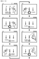
前記変化示唆演出実行手段は、変化示唆演出として、成功態様の変化示唆演出(図23−18(1)、(2)に示すように、キャラクタが投げたボールがアクティブ表示30TM003に命中して表示態様を変化させる演出)と、失敗態様の変化示唆演出(図23−19(10)、(20)に示すように、キャラクタが投げたボールがアクティブ表示30TM003に弾かれて表示態様を変化させない演出)を実行可能であり、
成功態様の変化示唆演出の実行回数に応じて、所定期間内(例えば、変動開始からリーチ状態が成立するまでの期間内、変動開始から飾り図柄(仮停止後に再変動(擬似連)が行われることになる飾り図柄の組み合わせ又は擬似連図柄)が仮停止するまでの期間内、変動開始から左中右の何れかの飾り図柄が最初に停止するまでの期間内)に次の変化示唆演出が実行される割合が異なる(例えば、図23−16に示すように、2回目の変化示唆演出が実行された段階において、2回とも成功態様だった場合には100%の割合で3回目の変化示唆演出が実行され、1回が成功態様であり1回が失敗態様だった場合には3回目の変化示唆演出が実行されない場合がある)。
このような構成によれば、演出効果を高めることができる。また、変化示唆演出の実行回数に対する注目度合いを高めて、興趣を向上させることができる。
(A) In order to achieve the above object, the gaming machine according to the present invention is
A gaming machine that has a variable display and can be controlled to an advantageous state that is advantageous to the player.
A setting means that can be set to any of the setting values of multiple stages based on the setting operation,
An advantageous state control means capable of executing control regarding the advantageous state based on a set value, and an advantageous state control means.
An information output means that can output setting value information that can specify which setting value is set, and
Based on the set value information output from the information output means, at least a predetermined suggestion effect that can be executed during the variable display, a specific suggestion effect that can be executed in the advantageous state, and a plurality of times based on the establishment of the predetermined condition. It is provided with a specific effect that can be executed over the variable display of the above, and an effect execution means that can execute a plurality of types of suggestive effects including a different execution ratio according to a set setting value.
The reliability of the suggestion of the set value differs depending on whether the predetermined suggestion effect is executed or the specific suggestion effect is executed.
The presentation execution means may be more capable of executing predetermined suggested directing a plurality of types of predetermined suggested state like including special predetermined suggested embodiment, the specific suggestions more plural kinds of specific suggestions state like including special specific suggestion embodiments The production can be performed,
If the predetermined suggested presentation by a special predetermined suggest embodiment is executed, the than the predetermined suggested presentation is performed by the different predetermined suggested embodiment is specially prescribed suggested embodiments, trust suggests a high advantageous set value High degree,
If said specific suggestion effect by special specified suggest embodiment is executed, the special specified than when the specific suggested presentation by different specific suggested embodiment is executed with the suggestion embodiment, trust suggests a high advantageous set value High degree,
When the set value information output from the information output means is not normal, the effect executing means does not execute the predetermined suggestion effect according to the special predetermined suggestion mode and the specific suggestion effect according to the special specific suggestion mode. , The predetermined suggestion effect according to a predetermined suggestion mode different from the special predetermined suggestion mode, and the specific suggestion effect according to a specific suggestion mode different from the special specific suggestion mode can be executed.
further,
Display control means that can display the corresponding display corresponding to the variable display,
It is provided with a change suggestion effect execution means capable of executing a change suggestion effect suggesting that the mode of the corresponding display changes.
The change suggestion effect execution means can execute the change suggestion effect of the success mode and the change suggestion effect of the failure mode as the change suggestion effect.
When the number of times the success mode change suggestion effect is executed in the predetermined period of the variable display is a predetermined number of times, the change is made in a specific period which is a period after the predetermined period of the variable display than when it is less than the predetermined number of times. It is characterized by a high rate of execution of suggestive effects.
According to such a configuration, in a gaming machine configured so that control of an advantageous state can be executed based on a set value, a specific effect can be executed over a plurality of variable displays, so that the effect can be enhanced. it can.
(1) Other gaming machines
A gaming machine (for example, pachinko gaming machine 1) that can be controlled to an advantageous state (for example, a jackpot gaming state) that is advantageous to the player.
A suggestion effect execution means (for example, effect control CPU 120) capable of executing a suggestion effect (for example, reach effect) suggesting that the control is performed in the advantageous state, and
A title notification means (for example, a production control CPU 120) capable of notifying a title corresponding to the suggestion effect is provided.
The title notification means can notify the title corresponding to the suggestion effect when a predetermined period has elapsed from the start of the suggestion effect (for example, FIGS. 9D and 9F).
further,
A display control means (
It is provided with a change suggestion effect execution means (effect control CPU 120) capable of executing a change suggestion effect suggesting that the mode of the corresponding display changes.
As the change suggestion effect, the change suggestion effect execution means displays the ball thrown by the character hitting the active display 30TM003 as shown in the change suggestion effect of the success mode (FIGS. 23-18 (1) and (2)). The effect of changing the mode) and the effect of suggesting the change of the failure mode (as shown in FIGS. 23-19 (10) and (20), the ball thrown by the character is repelled by the active display 30TM003 and does not change the display mode. ) Is feasible,
Depending on the number of executions of the change suggestion effect of the success mode, a decorative symbol (re-variation (pseudo-ream) is performed after the temporary stop) within a predetermined period (for example, from the start of the fluctuation to the establishment of the reach state). During the period until the combination of decorative symbols or the pseudo-continuous symbol) temporarily stops, and within the period from the start of fluctuation to the first stop of any of the decorative symbols on the left, middle, and right), the next change suggestion effect is displayed. The execution rate is different (for example, as shown in FIG. 23-16, when the second change suggestion effect is executed, if both are successful modes, the third change is performed at a rate of 100%. If the suggestion effect is executed and one is a success mode and one is a failure mode, the third change suggestion effect may not be executed).
According to such a configuration, the effect of production can be enhanced. In addition, it is possible to increase the degree of attention to the number of executions of the change suggestion effect and improve the interest.
(2)上記(1)の遊技機において、
前記示唆演出実行手段は、複数種類の前記示唆演出を実行可能であって、
複数種類の前記示唆演出において、前記所定期間内の演出の少なくとも一部は共通の態様で実行可能であるようにしてもよい(例えば図9(C))。
このような構成によれば、いずれの示唆演出が実行されるかに注目させることができ、興趣が向上する。
(2) In the gaming machine of (1) above
The suggestion effect execution means can execute a plurality of types of the suggestion effect, and
In the plurality of types of the suggestion effects, at least a part of the effects within the predetermined period may be feasible in a common manner (for example, FIG. 9C).
With such a configuration, it is possible to pay attention to which suggestive effect is executed, and the interest is improved.
(3)上記(1)または(2)の遊技機において、
前記示唆演出実行中の複数の実行タイミングにおいて、前記有利状態に制御されることを示唆する特定演出(例えば発展演出や予告演出)を実行可能であり、
前記所定期間中には前記特定演出の実行タイミングが設けられないようにしてもよい。
このような構成によれば、タイトルの報知後でも遊技者の期待感を維持することができる。
(3) In the gaming machine of (1) or (2) above
At a plurality of execution timings during the execution of the suggestion effect, it is possible to execute a specific effect (for example, a development effect or a notice effect) that suggests that the effect is controlled to the advantageous state.
The execution timing of the specific effect may not be provided during the predetermined period.
According to such a configuration, the player's expectation can be maintained even after the title is notified.
(4)上記(1)から(3)のいずれかの遊技機において、
前記示唆演出実行手段は、前記示唆演出として少なくとも第1示唆演出(例えばスーパーリーチAやスーパーリーチBのリーチ演出)と第2示唆演出(例えばスーパーリーチDやスーパーリーチEのリーチ演出)とを実行可能であり、
前記タイトル報知手段は、前記第2示唆演出では、当該第2示唆演出の開始時から当該第2示唆演出に対応したタイトルを報知するようにしてもよい。
このような構成によれば、示唆演出に応じたタイトルの報知を実行できるので演出効果が向上する。
(4) In any of the gaming machines (1) to (3) above,
The suggestion effect execution means executes at least a first suggestion effect (for example, a reach effect of super reach A or super reach B) and a second suggestion effect (for example, a reach effect of super reach D or super reach E) as the suggestion effect. It is possible
In the second suggestion effect, the title notification means may notify the title corresponding to the second suggestion effect from the start of the second suggestion effect.
According to such a configuration, the notification of the title according to the suggestion effect can be executed, so that the effect of the effect is improved.
(5)上記(4)の遊技機において、
前記第2示唆演出が実行された場合よりも前記第1示唆演出が実行された場合の方が前記有利状態に制御される割合が高いようにしてもよい。
このような構成によれば、演出効果が向上する。
(5) In the gaming machine of (4) above
The ratio of being controlled to the advantageous state may be higher when the first suggestion effect is executed than when the second suggestion effect is executed.
According to such a configuration, the effect of production is improved.
(6)上記(1)から(5)のいずれかの遊技機において、
前記示唆演出実行手段は、前記所定期間において報知されるタイトルに関連する演出態様で前記示唆演出を実行可能であるようにしてもよい。
このような構成によれば、演出効果が向上する。
(6) In any of the gaming machines (1) to (5) above,
The suggestion effect execution means may enable the suggestion effect to be executed in an effect mode related to the title notified in the predetermined period.
According to such a configuration, the effect of production is improved.
(7)上記(1)から(6)のいずれかの遊技機において、
遊技者の動作を検出可能な検出手段(例えばスティックコントローラ31Aやプッシュボタン31B)と、
前記検出手段に対応した特定表示(例えば小ボタン画像31AK043、大ボタン画像31AK047、スティック画像31AK051)を行う特定表示実行手段(例えば演出制御用CPU120)と、をさらに備え、
前記特定表示実行手段は、
前記特定表示として、第1特定表示(例えば小ボタン画像31AK043)と、前記第1特定表示よりも遊技者にとって有利度が高い第2特定表示(例えば、大ボタン画像31AK047、スティック画像31AK051)を表示可能であり、
前記検出手段による検出の非有効期間において、前記第1特定表示を表示した後に当該第1特定表示を前記第2特定表示に変化させ(例えば図17(E)、図18(I))、
前記検出手段による検出の有効期間において、変化後の前記第2特定表示を用いた動作演出が実行されるようにしてもよい(例えば図18(J)、(K))。
このような構成によれば、演出効果が向上する。
(7) In any of the gaming machines (1) to (6) above,
Detection means (for example,
A specific display execution means (for example, an effect control CPU 120) for performing a specific display (for example, small button image 31AK043, large button image 31AK047, stick image 31AK051) corresponding to the detection means is further provided.
The specific display execution means is
As the specific display, a first specific display (for example, small button image 31AK043) and a second specific display (for example, large button image 31AK047, stick image 31AK051) that are more advantageous to the player than the first specific display are displayed. It is possible and
During the non-valid period of detection by the detection means, after displaying the first specific display, the first specific display is changed to the second specific display (for example, FIGS. 17 (E) and 18 (I)).
During the valid period of detection by the detection means, the operation effect using the second specific display after the change may be executed (for example, FIGS. 18 (J) and 18 (K)).
According to such a configuration, the effect of production is improved.
(8)上記(1)から(7)のいずれかの遊技機において、
前記有利状態への制御の期待度を示唆する示唆表示として、表示サイズが第1サイズである第1示唆表示(図19(a)に示すシャッター演出時に表示する第1サイズのシャッター画像31AK061による表示等)と、表示サイズが第2サイズである第2示唆表示(図19(d)に示すリーチタイトル演出時に表示する第2サイズのリーチタイトル画像31AK062等)とを表示可能な表示手段(例えば画像表示装置5、演出制御用CPU120)をさらに備え、
前記表示手段は、
態様の異なる複数種類の要素(図19(a)、(d)に示す要素E1(バナナ)、要
素E2(メロン)、要素E3(リンゴ)、要素E4(スイカ)、要素E5(イチゴ)等)を含んで構成された特定画像(図19(a)、(d)に示すフルーツ柄等)を表示可能であり、
前記特定画像を含むパターンにて前記第1示唆表示および前記第2示唆表示のいずれを表示するときにも、複数種類の要素が前記第1示唆表示および前記第2示唆表示のいずれにも含まれるように表示する(図19(a)、(d)に示すシャッター画像31AK061、リーチタイトル画像31AK062のいずれにも要素E1〜E5が含まれるように表示する等)ようにしてもよい。
このような構成によれば、示唆表示の表示サイズに関わらず特定画像を好適に表示することができる。これにより、特定画像が表示されたことを正確に伝えることができる。
(8) In any of the gaming machines (1) to (7) above,
As a suggestion display suggesting the degree of expectation of control to the advantageous state, a first suggestion display having a display size of the first size (display by the first size shutter image 31AK061 displayed at the time of the shutter effect shown in FIG. 19A). Etc.) and a second suggestion display having a display size of the second size (second size reach title image 31AK062 or the like displayed at the time of the reach title production shown in FIG. 19D) can be displayed (for example, an image). A
The display means
Multiple types of elements having different aspects (element E1 (banana), element E2 (melon), element E3 (apple), element E4 (watermelon), element E5 (strawberry), etc. shown in FIGS. 19 (a) and 19 (d)) It is possible to display a specific image (such as the fruit pattern shown in FIGS. 19A and 19D) composed of the above.
When either the first suggestion display or the second suggestion display is displayed in the pattern including the specific image, a plurality of types of elements are included in both the first suggestion display and the second suggestion display. (Display so that elements E1 to E5 are included in any of the shutter image 31AK061 and the reach title image 31AK062 shown in FIGS. 19A and 19D).
According to such a configuration, a specific image can be preferably displayed regardless of the display size of the suggestion display. This makes it possible to accurately convey that a specific image has been displayed.
また、後述する発明を実施するための形態には、以下の(9)〜(14)に係る発明が含まれる。従来より、遊技機において、特開2016−144583号公報(図36)に示されているような、可変表示に対応した情報としてアクティブ表示が表示され、擬似連変動が実行される毎にアクティブ表示の表示態様を変化させる遊技機があった。上記した従来の遊技機では、可変表示に対応した情報に関する興趣を向上させる余地があり、この点に鑑み、可変表示に対応した情報に関する興趣を向上させる遊技機の提供が求められている。 In addition, the embodiments for carrying out the invention described later include the following inventions (9) to (14). Conventionally, in a gaming machine, an active display is displayed as information corresponding to a variable display as shown in Japanese Patent Application Laid-Open No. 2016-144583 (FIG. 36), and the active display is displayed every time a pseudo-continuous variation is executed. There was a gaming machine that changed the display mode of. In the above-mentioned conventional gaming machines, there is room for improving the interest in information corresponding to variable display, and in view of this point, it is required to provide a gaming machine for improving the interest in information corresponding to variable display.
(9) 上記目的を達成するため、別態様による遊技機は、
可変表示(特別図柄の変動表示、飾り図柄の変動表示)を実行可能な遊技機(パチンコ遊技機1)であって、
可変表示に対応した対応表示(アクティブ表示30TM003)を表示可能な表示制御手段(演出制御用CPU120)と、
対応表示の態様が変化することを示唆する変化示唆演出を実行可能な変化示唆演出実行手段(演出制御用CPU120)と、を備え、
前記変化示唆演出実行手段は、変化示唆演出として、成功態様の変化示唆演出(図23−18(1)、(2)に示すように、キャラクタが投げたボールがアクティブ表示30TM003に命中して表示態様を変化させる演出)と、失敗態様の変化示唆演出(図23−19(10)、(20)に示すように、キャラクタが投げたボールがアクティブ表示30TM003に弾かれて表示態様を変化させない演出)を実行可能であり、
成功態様の変化示唆演出の実行回数に応じて、所定期間内(例えば、変動開始からリーチ状態が成立するまでの期間内、変動開始から飾り図柄(仮停止後に再変動(擬似連)が行われることになる飾り図柄の組み合わせ又は擬似連図柄)が仮停止するまでの期間内、変動開始から左中右の何れかの飾り図柄が最初に停止するまでの期間内)に次の変化示唆演出が実行される割合が異なる(例えば、図23−16に示すように、2回目の変化示唆演出が実行された段階において、2回とも成功態様だった場合には100%の割合で3回目の変化示唆演出が実行され、1回が成功態様であり1回が失敗態様だった場合には3回目の変化示唆演出が実行されない場合がある)
ことを特徴とする。
このような構成によれば、変化示唆演出の実行回数に対する注目度合いを高めて、興趣を向上させることができる。
(9) In order to achieve the above objectives, the gaming machine according to another aspect is
It is a gaming machine (pachinko gaming machine 1) that can execute variable display (variable display of special symbols, variable display of decorative symbols).
A display control means (
It is provided with a change suggestion effect execution means (effect control CPU 120) capable of executing a change suggestion effect suggesting that the mode of the corresponding display changes.
As the change suggestion effect, the change suggestion effect execution means displays the ball thrown by the character hitting the active display 30TM003 as shown in the change suggestion effect of the success mode (FIGS. 23-18 (1) and (2)). The effect of changing the mode) and the effect of suggesting the change of the failure mode (as shown in FIGS. 23-19 (10) and (20), the ball thrown by the character is repelled by the active display 30TM003 and does not change the display mode. ) Is feasible,
Depending on the number of executions of the change suggestion effect of the success mode, a decorative symbol (re-variation (pseudo-ream) is performed after the temporary stop) within a predetermined period (for example, within the period from the start of the fluctuation to the establishment of the reach state). The next change suggestion effect will be displayed during the period until the combination of decorative symbols or the pseudo-continuous symbol) temporarily stops, and within the period from the start of fluctuation to the first stop of any of the decorative symbols on the left, middle, and right. The execution rate is different (for example, as shown in FIG. 23-16, when the second change suggestion effect is executed, if both are successful modes, the third change is performed at a rate of 100%. If the suggestion effect is executed and one is a success mode and one is a failure mode, the third change suggestion effect may not be executed.)
It is characterized by that.
According to such a configuration, it is possible to increase the degree of attention to the number of executions of the change suggestion effect and improve the interest.
(10)の遊技機は、
(9)の遊技機であって、
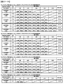
対応表示(アクティブ表示30TM003)の態様に応じて、遊技者にとって有利な有利状態(大当り遊技状態)に制御される割合が異なり(図23−3(A)に示すように、アクティブ表示の最終表示態様によって大当り期待度が異なり)、
成功態様の変化示唆演出が連続した回数に応じて、対応表示が何れの態様となるかの割合が異なる(図23−16(A)に示すように、成功態様の変化示唆演出が連続する回数が多いほど大当り期待度が高く、同じ表示色のアクティブ表示であっても成功態様の変化示唆演出が連続する回数が多い方が大当り期待度が高い)
ことを特徴とする。
このような構成によれば、成功態様の変化示唆演出が連続した回数に関心を持たせることができ、興趣を向上させることができる。
The gaming machine of (10) is
The gaming machine of (9)
Depending on the mode of the corresponding display (active display 30TM003), the ratio controlled to the advantageous state (big hit game state) advantageous to the player differs (as shown in FIG. 23-3 (A), the final display of the active display). Expectations for big hits differ depending on the mode),
Depending on the number of times the change suggestion effect of the success mode is continuous, the ratio of which mode the corresponding display is is different (as shown in FIG. 23-16 (A), the number of times the change suggestion effect of the success mode is continuous. The higher the number of hits, the higher the expectation of big hits. Even if the active display has the same display color, the higher the number of consecutive changes suggestion effects of the success mode, the higher the expectation of big hits.)
It is characterized by that.
According to such a configuration, it is possible to pay attention to the number of times in which the change suggestion effect of the success mode is continuous, and it is possible to improve the interest.
(11)の遊技機は、
(9)又は(10)の遊技機であって、
飾り図柄の可変表示を実行可能であり、
変化示唆演出が実行されているときには、飾り図柄の可変表示態様が変化しない(図23−18に示すように、変化示唆演出が実行されているときは飾り図柄の変動表示に関して仮停止が行われず変動方向も変化しない)
ことを特徴とする。
このような構成によれば、飾り図柄の可変表示態様が変化しないことにより、変化示唆演出に一層注目させることができる。
The gaming machine of (11) is
The gaming machine of (9) or (10)
Variable display of decorative patterns is possible,
When the change suggestion effect is executed, the variable display mode of the decorative symbol does not change (as shown in FIGS. 23-18, when the change suggestion effect is executed, the temporary stop is not performed for the variable display of the decorative symbol. The direction of fluctuation does not change either)
It is characterized by that.
According to such a configuration, the change suggestion effect can be further focused on because the variable display mode of the decorative pattern does not change.
(12)の遊技機は、
(9)〜(11)から選択される何れかの遊技機であって、
前記変化示唆演出実行手段(演出制御用CPU120)は、複数種類の変化示唆演出(例えば、キャラクタAが登場する変化示唆演出及びキャラクタBが登場する変化示唆演出)を実行可能であり、
1の種類の変化示唆演出を実行した後に、異なる種類の変化示唆演出を実行可能である(例えば、図23−18(1)に示すように、キャラクタAが登場する変化示唆演出を実行した後に、図23−18(4)に示すように、キャラクタBが登場する変化示唆演出を実行する)
ことを特徴とする。
このような構成によれば、変化示唆演出の多様化を図ることができる。
The gaming machine of (12) is
Any gaming machine selected from (9) to (11).
The change suggestion effect execution means (
After executing one type of change suggestion effect, it is possible to execute a different type of change suggestion effect (for example, after executing the change suggestion effect in which the character A appears, as shown in FIG. 23-18 (1)). , As shown in FIG. 23-18 (4), the change suggestion effect in which the character B appears is executed.)
It is characterized by that.
With such a configuration, it is possible to diversify the change suggestion effect.
(13)の遊技機は、
(9)〜(12)から選択される何れかの遊技機であって、
前記変化示唆演出実行手段(演出制御用CPU120)は、複数種類の変化示唆演出(例えば、キャラクタAが登場する変化示唆演出、キャラクタBが登場する変化示唆演出、キャラクタCが登場する変化示唆演出、キャラクタDが登場する変化示唆演出)を実行可能であり、
変化示唆演出の種類に応じて、成功態様の変化示唆演出が実行される割合が異なり、特定態様の対応表示に変化する割合が異なる(例えば、図23−17に示すように、キャラクタAよりもキャラクタDの方が、成功態様の変化示唆演出が実行される割合が高く、アクティブ表示の表示態様が変化する割合が高い)
ことを特徴とする。
このような構成によれば、何れの種類の変化示唆演出が実行されるかに興味を持たせることができる。
The gaming machine of (13) is
Any gaming machine selected from (9) to (12).
The change suggestion effect execution means (
Depending on the type of change suggestion effect, the rate at which the change suggestion effect of the success mode is executed is different, and the rate of change to the corresponding display of the specific mode is different (for example, as shown in FIG. 23-17, the rate is higher than that of the character A. Character D has a higher rate of executing the change suggestion effect of the success mode, and a higher rate of changing the display mode of the active display).
It is characterized by that.
With such a configuration, it is possible to be interested in which kind of change suggestion effect is executed.
(14)の遊技機は、
(9)〜(13)から選択される何れかの遊技機であって、
前記変化示唆演出実行手段(演出制御用CPU120)は、複数種類の変化示唆演出(キャラクタAが登場する変化示唆演出、キャラクタBが登場する変化示唆演出、キャラクタCが登場する変化示唆演出、キャラクタDが登場する変化示唆演出)を実行可能であり、
変化示唆演出の種類に応じて、次の変化示唆演出が実行される割合が異なる(図23−17に示すように、キャラクタDよりもキャラクタAの方が、次の変化示唆演出が実行される割合が高い)
ことを特徴とする遊技機。
このような構成によれば、何れの種類の変化示唆演出が実行されるかに興味を持たせることができる。
The gaming machine of (14) is
Any gaming machine selected from (9) to (13).
The change suggestion effect execution means (
The rate at which the next change suggestion effect is executed differs depending on the type of change suggestion effect (as shown in FIG. 23-17, character A executes the next change suggestion effect more than character D). High percentage)
A gaming machine characterized by that.
With such a configuration, it is possible to be interested in which kind of change suggestion effect is executed.
特開2014−117517号公報(図18)に示すように、可変表示に対応した情報として、保留アイコンを多様な表示態様で表示することができる遊技機が提案されている。特開2014−117517号公報(図18)に記載されたような遊技機では、可変表示に対応した情報に関する興趣を向上させる余地がある。手段K1〜K7に係る発明は、上記の実状に鑑みてなされたものであり、可変表示に対応した情報に関する興趣を向上させる遊技機を提供することにある。 As shown in Japanese Patent Application Laid-Open No. 2014-117517 (FIG. 18), a gaming machine capable of displaying a hold icon in various display modes has been proposed as information corresponding to variable display. In a gaming machine as described in Japanese Patent Application Laid-Open No. 2014-117517 (FIG. 18), there is room for improving the interest in information corresponding to variable display. The inventions according to the means K1 to K7 have been made in view of the above-mentioned actual conditions, and an object of the present invention is to provide a gaming machine that improves interest in information corresponding to variable display.
手段K1の遊技機は、
可変表示(特別図柄の変動表示、飾り図柄の変動表示)を実行可能な遊技機(パチンコ遊技機1)であって、
可変表示に対応した情報(第1保留表示30TM001、第2保留表示30TM002、アクティブ表示30TM003、副保留表示30TM004、副アクティブ表示30TM005)の表示制御を実行する表示制御手段(演出制御用CPU120)を備え、
前記表示制御手段は、第1情報表示領域(第1保留表示領域30TM101、アクティブ表示領域30TM103)において、可変表示に対応した第1情報(第1保留表示30TM001、アクティブ表示30TM003)の表示制御を実行可能であると共に、前記第1情報表示領域とは異なる第2情報表示領域(副保留表示領域30TM104、副アクティブ表示領域30TM105)において、第1情報に対応した可変表示と共通の可変表示に対応した第2情報(副保留表示30TM004、副アクティブ表示30TM005)の表示制御を実行可能であり、
第1情報の態様が変化する割合と、第2情報の態様が変化する割合とが異なる(図23−3に示すように、アクティブ表示30TM003よりも副アクティブ表示30TM005の方が最終表示態様として通常態様とは異なる態様が選択される割合が低く、第1保留表示30TM001よりも副保留表示30TM004の方が表示態様が変化しにくい)
ことを特徴とする。
このような構成によれば、共通の可変表示に対応した情報として、第1情報及び第2情報という複数種類の情報を表示可能であることにより、可変表示に対応した情報に関する興趣を向上させることができるとともに、第1情報及び第2情報の態様に関心を持たせることができる。
The gaming machine of means K1
It is a gaming machine (pachinko gaming machine 1) that can execute variable display (variable display of special symbols, variable display of decorative symbols).
A display control means (
The display control means executes display control of the first information (first hold display 30TM001, active display 30TM003) corresponding to variable display in the first information display area (first hold display area 30TM101, active display area 30TM103). In addition to being possible, in the second information display area (sub-hold display area 30TM104, sub-active display area 30TM105) different from the first information display area, the variable display corresponding to the first information and the common variable display are supported. The display control of the second information (secondary hold display 30TM004, sub-active display 30TM005) can be executed.
The rate at which the mode of the first information changes is different from the rate at which the mode of the second information changes (as shown in FIG. 23-3, the sub-active display 30TM005 is usually the final display mode rather than the active display 30TM003. The rate at which a mode different from the mode is selected is low, and the display mode of the sub-hold display 30TM004 is less likely to change than that of the first hold display 30TM001).
It is characterized by that.
According to such a configuration, it is possible to display a plurality of types of information, that is, the first information and the second information as the information corresponding to the common variable display, thereby improving the interest in the information corresponding to the variable display. At the same time, it is possible to be interested in the aspects of the first information and the second information.
手段K2の遊技機は、
手段K1の遊技機であって、
変化後の第1情報の態様と、変化後の第2情報の態様とが異なる(図23−8(6)に示すように、青色態様の第1保留表示30TM001bは青色の丸形表示であり、青色態様の副保留表示30TM004bは青色の星形表示である)
ことを特徴とする。
このような構成によれば、第1情報と第2情報とで変化後の態様が異なるため、それぞれの情報を明確に区別して把握させることができる。
The gaming machine of means K2 is
Means K1 gaming machine
The mode of the first information after the change and the mode of the second information after the change are different (as shown in FIG. 23-8 (6), the first hold display 30TM001b in the blue mode is a blue round display. , Sub-hold display 30TM004b in blue mode is a blue star display)
It is characterized by that.
According to such a configuration, since the first information and the second information have different modes after the change, the respective information can be clearly distinguished and grasped.
手段K3の遊技機は、
手段K1又は手段K2の遊技機であって、
前記表示制御手段(演出制御用CPU120)は、第1情報(第1保留表示30TM001、アクティブ表示30TM003)と第2情報(副保留表示30TM004、副アクティブ表示)とを同時に表示させることが可能であり(図23−8(2)に示すように、第1保留表示30TM001及びアクティブ表示30TM003、並びに、副保留表示30TM004及び副アクティブ表示30TM005を同時に表示可能であり)、
変化後の第1情報の態様と、変化後の第2情報の態様とに応じて、遊技者にとって有利な有利状態に制御される割合が異なる(例えば、図23−3に示すように、アクティブ表示30TM003の最終表示態様が通常態様であり且つ副アクティブ表示30TM005の最終表示態様が通常態様である場合よりも、アクティブ表示30TM003の最終表示態様が金色態様であり且つ副アクティブ表示30TM005の最終表示態様が赤色態様である場合の方が大当り期待度は高くなる)
ことを特徴とする。
このような構成によれば、第1情報の態様と第2情報の態様との組合せに注目させることができ、興趣を向上させることができる。
The gaming machine of means K3 is
A gaming machine of means K1 or means K2.
The display control means (effect control CPU 120) can simultaneously display the first information (first hold display 30TM001, active display 30TM003) and the second information (sub-hold display 30TM004, sub-active display). (As shown in FIG. 23-8 (2), the first hold display 30TM001 and the active display 30TM003, and the sub-hold display 30TM004 and the sub-active display 30TM005 can be displayed at the same time).
Depending on the mode of the first information after the change and the mode of the second information after the change, the ratio controlled to the advantageous state favorable to the player differs (for example, as shown in FIG. 23-3, active). The final display mode of the active display 30TM003 is a golden mode and the final display mode of the sub-active display 30TM005 is higher than the case where the final display mode of the display 30TM003 is the normal mode and the final display mode of the sub-active display 30TM005 is the normal mode. The jackpot expectation is higher when is in the red mode)
It is characterized by that.
According to such a configuration, it is possible to pay attention to the combination of the mode of the first information and the mode of the second information, and it is possible to improve the interest.
手段K4の遊技機は、
手段K1〜手段K3から選択される何れかの遊技機であって、
前記表示制御手段(演出制御用CPU120)は、
第1情報としての第1保留表示(第1保留表示30TM001)を前記第1情報表示領域(第1保留表示領域30TM101)に表示するとともに、実行中の可変表示に対応した第1対応表示(アクティブ表示30TM003)を前記第1情報表示領域(アクティブ表示領域30TM103)に表示し、
第1保留表示に対応した可変表示を開始するときに、当該可変表示に対応した第1対応表示を、当該第1保留表示と共通の態様により表示させることが可能であり(図23−9(9)、(10)に示すように、赤色態様の第1保留表示30TM001c(赤色の丸形表示)がアクティブ表示領域30TM103にシフトすると、同じ表示色である赤色態様のアクティブ表示30TM003c(赤色の丸形表示)が表示され)、
第2情報としての第2保留表示(副保留表示30TM004)を前記第2情報表示領域(副保留表示領域30TM104、副アクティブ表示領域30TM105)に表示するとともに、実行中の可変表示に対応した第2対応表示(副アクティブ表示30TM005)を前記第2情報表示領域(副保留表示領域30TM104、副アクティブ表示領域30TM105)に表示し、
第2保留表示に対応した可変表示を開始するときに、当該可変表示に対応した第2対応表示を、当該第2保留表示と共通の態様により表示させることが可能である(図23−9(9)、(10)に示すように、赤色態様の副保留表示30TM004c(赤色の星形表示)が副アクティブ表示領域30TM105にシフトすると、同じ表示色である赤色態様の副アクティブ表示30TM005c(赤色の星形表示)が表示される)
ことを特徴とする。
このような構成によれば、実行中の可変表示に対応した情報として、第1対応情報及び第2対応情報という複数種類の情報を表示可能であることにより、可変表示に対応した情報に関する興趣を向上させることができるとともに、第1対応情報及び第2対応情報の態様に関心を持たせることができる。
The gaming machine of means K4 is
Any gaming machine selected from means K1 to means K3.
The display control means (
The first hold display (first hold display 30TM001) as the first information is displayed in the first information display area (first hold display area 30TM101), and the first corresponding display (active) corresponding to the variable display during execution is displayed. Display 30TM003) is displayed in the first information display area (active display area 30TM103).
When starting the variable display corresponding to the first hold display, it is possible to display the first corresponding display corresponding to the variable display in the same manner as the first hold display (FIG. 23-9 (FIG. 23-9). As shown in 9) and (10), when the first hold display 30TM001c (red circle display) in the red mode shifts to the active display area 30TM103, the active display 30TM003c (red circle) in the red mode having the same display color Shape display) is displayed),
The second hold display (sub-hold display 30TM004) as the second information is displayed in the second information display area (secondary hold display area 30TM104, sub-active display area 30TM105), and the second is corresponding to the variable display during execution. The corresponding display (sub-active display 30TM005) is displayed in the second information display area (sub-hold display area 30TM104, sub-active display area 30TM105).
When starting the variable display corresponding to the second hold display, it is possible to display the second corresponding display corresponding to the variable display in the same manner as the second hold display (FIG. 23-9 (FIG. 23-9). As shown in 9) and (10), when the sub-hold display 30TM004c (red star-shaped display) in the red mode shifts to the sub-active display area 30TM105, the sub-active display 30TM005c (red) in the red mode, which has the same display color, is displayed. Star-shaped display) is displayed)
It is characterized by that.
According to such a configuration, it is possible to display a plurality of types of information, that is, the first correspondence information and the second correspondence information as the information corresponding to the variable display during execution, so that the information related to the variable display can be displayed. It can be improved and the mode of the first correspondence information and the second correspondence information can be interested.
手段K5の遊技機は、
手段K1〜手段K4から選択される何れかの遊技機であって、
遊技者にとって有利な有利状態(大当り遊技状態)に制御されるか否かを報知する報知演出(リーチ演出)を実行可能な報知演出実行手段(演出制御用CPU120)を備え、
前記第1情報表示領域(第1保留表示領域30TM101、アクティブ表示領域30TM103)の少なくとも一部は、前記報知演出が実行される領域に含まれ、
前記表示制御手段(演出制御用CPU120)は、前記報知演出が実行されることに伴い第1情報を非表示とすることが可能である一方、前記報知演出が実行されているときにも第2情報は視認可能とする(図23−9(11)に示すように、リーチ状態が成立すると、「リーチ!!」という文字が画面下部に表示されることに伴い、第1保留表示30TM001及びアクティブ表示30TM003が非表示になる一方、副保留表示30TM004及び副アクティブ表示30TM005は継続して表示される)
ことを特徴とする。
このような構成によれば、第1情報を非表示とすることで報知演出に対する注目を高めるとともに、第2情報を継続して表示することで、報知演出の実行中も可変表示に対する情報を確認可能とすることができる。
The gaming machine of means K5 is
Any gaming machine selected from means K1 to means K4.
It is provided with a notification effect execution means (effect control CPU 120) capable of executing a notification effect (reach effect) for notifying whether or not the player is controlled to an advantageous state (big hit game state) that is advantageous to the player.
At least a part of the first information display area (first hold display area 30TM101, active display area 30TM103) is included in the area where the notification effect is executed.
The display control means (effect control CPU 120) can hide the first information as the notification effect is executed, while the second information is also displayed when the notification effect is executed. The information is visible (as shown in FIG. 23-9 (11), when the reach state is established, the characters "reach !!" are displayed at the bottom of the screen, and the first hold display 30TM001 and active. While the display 30TM003 is hidden, the sub-hold display 30TM004 and the sub-active display 30TM005 are continuously displayed).
It is characterized by that.
According to such a configuration, the first information is hidden to raise the attention to the notification effect, and the second information is continuously displayed to confirm the information for the variable display even during the execution of the notification effect. It can be possible.
手段K6の遊技機は、
手段K1〜手段K5から選択される何れかの遊技機であって、
前記表示制御手段(演出制御用CPU120)は、実行中の可変表示に対応した第1対応表示(アクティブ表示30TM003)を前記第1情報表示領域(第1保留表示領域30TM101、アクティブ表示領域30TM103)に表示し、実行中の可変表示に対応した第2対応表示(副アクティブ表示30TM005)を前記第2情報表示領域(副保留表示領域30TM104、副アクティブ表示領域30TM105)に表示し、
第1対応表示の態様が変化するときに実行される第1作用演出と、第2対応表示の態様が変化するときに実行される第2作用演出とで、演出の態様が異なる(例えば、アクティブ表示30TM003の表示態様を変化させるアクティブ作用演出は、キャラクタAが出現してボールを投げるアクションを実行する態様であり、副アクティブ表示30TM005の表示態様を変化させる副アクティブ作用演出は、キャラクタaが出現して風船を飛ばすアクションを実行する態様である)
ことを特徴とする。
このような構成によれば、第1作用演出と第2作用演出の態様が異なることにより、興趣を向上させることができる。
The gaming machine of means K6 is
Any gaming machine selected from means K1 to means K5.
The display control means (effect control CPU 120) shifts the first corresponding display (active display 30TM003) corresponding to the variable display during execution to the first information display area (first hold display area 30TM101, active display area 30TM103). The second corresponding display (secondary active display 30TM005) corresponding to the variable display during execution is displayed in the second information display area (secondary hold display area 30TM104, secondary active display area 30TM105).
The mode of the effect is different between the first action effect executed when the mode of the first correspondence display changes and the second action effect executed when the mode of the second correspondence display changes (for example, active). The active action effect that changes the display mode of the display 30TM003 is a mode in which the character A appears and executes an action of throwing a ball, and the subactive action effect that changes the display mode of the subactive display 30TM005 is a mode in which the character a appears. It is a mode to execute the action of flying a balloon)
It is characterized by that.
According to such a configuration, the first action effect and the second action effect are different in mode, so that the interest can be improved.
手段K7の遊技機は、
手段K1〜手段K6から選択される何れかの遊技機であって、
前記表示制御手段(演出制御用CPU120)は、第1情報としての第1保留表示(第1保留表示30TM001)を前記第1情報表示領域(第1保留表示領域30TM101)に表示し、第2情報としての第2保留表示(副保留表示30TM004)を前記第2情報表示領域(副保留表示領域30TM104)に表示し、
第1保留表示の態様が変化したときと、第2保留表示の態様が変化したときとで、遊技者にとって有利な有利状態に制御される割合が異なる(図23−3に示すように、アクティブ表示30TM003の表示態様が変化した場合よりも副アクティブ表示30TM005の表示態様が変化した場合の方が大当り期待度は高く、第1保留表示30TM001の表示態様が変化した場合よりも副保留表示30TM004の表示態様が変化した場合の方が大当り期待度は高くなる)
ことを特徴とする。
このような構成によれば、第1保留表示及び第2保留表示の何れの態様が変化したかに注目させることができる。
The gaming machine of means K7 is
Any gaming machine selected from means K1 to means K6.
The display control means (effect control CPU 120) displays the first hold display (first hold display 30TM001) as the first information in the first information display area (first hold display area 30TM101), and displays the second information. The second hold display (secondary hold display 30TM004) is displayed in the second information display area (secondary hold display area 30TM104).
When the mode of the first hold display is changed and when the mode of the second hold display is changed, the ratio of being controlled to the advantageous state favorable to the player is different (as shown in FIG. 23-3, active). The big hit expectation is higher when the display mode of the sub-active display 30TM005 is changed than when the display mode of the display 30TM003 is changed, and the sub-hold display 30TM004 is higher than when the display mode of the first hold display 30TM001 is changed. The jackpot expectation is higher when the display mode changes)
It is characterized by that.
With such a configuration, it is possible to pay attention to which mode of the first hold display and the second hold display has changed.
特開2014−117517号公報(図18)に示すように、可変表示に対応した情報として、保留アイコンを多様な表示態様で表示することができる遊技機が提案されている。特開2014−117517号公報(図18)に記載されたような遊技機では、可変表示に対応した情報に関する興趣を向上させる余地がある。手段L1〜手段L7に係る発明は、上記の実状に鑑みてなされたものであり、可変表示に対応した情報に関する興趣を向上させる遊技機を提供することにある。 As shown in Japanese Patent Application Laid-Open No. 2014-117517 (FIG. 18), a gaming machine capable of displaying a hold icon in various display modes has been proposed as information corresponding to variable display. In a gaming machine as described in Japanese Patent Application Laid-Open No. 2014-117517 (FIG. 18), there is room for improving the interest in information corresponding to variable display. The invention according to the means L1 to the means L7 has been made in view of the above-mentioned actual conditions, and an object of the present invention is to provide a gaming machine for improving the interest in information corresponding to variable display.
手段L1の遊技機は、
可変表示(特別図柄の変動表示、飾り図柄の変動表示)を実行可能な遊技機(パチンコ遊技機1)であって、
可変表示に対応した情報(第1保留表示30TM001、第2保留表示30TM002、アクティブ表示30TM003、副保留表示30TM004、副アクティブ表示30TM005)の表示制御を実行する表示制御手段(演出制御用CPU120)を備え、
前記表示制御手段は、第1情報表示領域(第1保留表示領域30TM101、アクティブ表示領域30TM103)において、可変表示に対応した第1情報(第1保留表示30TM001、アクティブ表示30TM003)の表示制御を実行可能であると共に、前記第1情報表示領域とは異なる第2情報表示領域(副保留表示領域30TM104、副アクティブ表示領域30TM105)において、第1情報に対応した可変表示と共通の可変表示に対応した第2情報(副保留表示30TM004、副アクティブ表示30TM005)の表示制御を実行可能であり、
第1情報の態様が変化したときに、前記第1情報表示領域とは異なる表示領域における予告演出の少なくとも一部を実行しない(図23−11に示すように、第1保留表示30TM001の態様が変化したときには、副保留表示領域30TM104に副保留表示30TM004が表示されず副アクティブ表示領域30TM105に副アクティブ表示30TM005が表示されない)
ことを特徴とする。
このような構成によれば、共通の可変表示に対応した情報として、第1情報及び第2情報という複数種類の情報を表示可能な遊技機において、演出の複雑化を抑制し、興趣を向上させることができる。
The gaming machine of means L1
It is a gaming machine (pachinko gaming machine 1) that can execute variable display (variable display of special symbols, variable display of decorative symbols).
A display control means (
The display control means executes display control of the first information (first hold display 30TM001, active display 30TM003) corresponding to variable display in the first information display area (first hold display area 30TM101, active display area 30TM103). In addition to being possible, in the second information display area (sub-hold display area 30TM104, sub-active display area 30TM105) different from the first information display area, the variable display corresponding to the first information and the common variable display are supported. The display control of the second information (secondary hold display 30TM004, sub-active display 30TM005) can be executed.
When the mode of the first information changes, at least a part of the advance notice effect in the display area different from the first information display area is not executed (as shown in FIG. 23-11, the mode of the first hold display 30TM001 is When changed, the sub-hold display 30TM004 is not displayed in the sub-hold display area 30TM104, and the sub-active display 30TM005 is not displayed in the sub-active display area 30TM105.)
It is characterized by that.
According to such a configuration, in a gaming machine capable of displaying a plurality of types of information, that is, first information and second information as information corresponding to a common variable display, the complexity of the production is suppressed and the interest is improved. be able to.
手段L2の遊技機は、
手段L1の遊技機であって、
変化後の第1情報の態様と、変化後の第2情報の態様とが異なる(図23−8(6)に示すように、青色態様の第1保留表示30TM001bは青色の丸形表示であり、青色態様の副保留表示30TM004bは青色の星形表示である)
ことを特徴とする。
このような構成によれば、第1情報と第2情報とで変化後の態様が異なるため、それぞれの情報を明確に区別して把握させることができる。
The gaming machine of means L2 is
Means L1 gaming machine
The mode of the first information after the change and the mode of the second information after the change are different (as shown in FIG. 23-8 (6), the first hold display 30TM001b in the blue mode is a blue round display. , Sub-hold display 30TM004b in blue mode is a blue star display)
It is characterized by that.
According to such a configuration, since the first information and the second information have different modes after the change, the respective information can be clearly distinguished and grasped.
手段L3の遊技機は、
手段L1又は手段L2の遊技機であって、
前記表示制御手段(演出制御用CPU120)は、第1情報(第1保留表示30TM001、アクティブ表示30TM003)と第2情報(副保留表示30TM004、副アクティブ表示)とを同時に表示させることが可能であり(図23−8(2)に示すように、第1保留表示30TM001及びアクティブ表示30TM003、並びに、副保留表示30TM004及び副アクティブ表示30TM005を同時に表示可能であり)、
変化後の第1情報の態様と、変化後の第2情報の態様とに応じて、遊技者にとって有利な有利状態に制御される割合が異なる(例えば、図23−3に示すように、アクティブ表示30TM003の最終表示態様が通常態様であり且つ副アクティブ表示30TM005の最終表示態様が通常態様である場合よりも、アクティブ表示30TM003の最終表示態様が金色態様であり且つ副アクティブ表示30TM005の最終表示態様が赤色態様である場合の方が大当り期待度は高くなる)
ことを特徴とする。
このような構成によれば、第1情報の態様と第2情報の態様との組合せに注目させることができ、興趣を向上させることができる。
The gaming machine of means L3 is
A gaming machine of means L1 or means L2.
The display control means (effect control CPU 120) can simultaneously display the first information (first hold display 30TM001, active display 30TM003) and the second information (sub-hold display 30TM004, sub-active display). (As shown in FIG. 23-8 (2), the first hold display 30TM001 and the active display 30TM003, and the sub-hold display 30TM004 and the sub-active display 30TM005 can be displayed at the same time).
Depending on the mode of the first information after the change and the mode of the second information after the change, the ratio controlled to the advantageous state favorable to the player differs (for example, as shown in FIG. 23-3, active). The final display mode of the active display 30TM003 is a golden mode and the final display mode of the sub-active display 30TM005 is higher than the case where the final display mode of the display 30TM003 is the normal mode and the final display mode of the sub-active display 30TM005 is the normal mode. The jackpot expectation is higher when is in the red mode)
It is characterized by that.
According to such a configuration, it is possible to pay attention to the combination of the mode of the first information and the mode of the second information, and it is possible to improve the interest.
手段L4の遊技機は、
手段L1〜手段L3から選択される何れかの遊技機であって、
前記表示制御手段(演出制御用CPU120)は、
第1情報としての第1保留表示(第1保留表示30TM001)を前記第1情報表示領域(第1保留表示領域30TM101)に表示するとともに、実行中の可変表示に対応した第1対応表示(アクティブ表示30TM003)を前記第1情報表示領域(アクティブ表示領域30TM103)に表示し、
第1保留表示に対応した可変表示を開始するときに、当該可変表示に対応した第1対応表示を、当該第1保留表示と共通の態様により表示させることが可能であり(図23−9(9)、(10)に示すように、赤色態様の第1保留表示30TM001c(赤色の丸形表示)がアクティブ表示領域30TM103にシフトすると、同じ表示色である赤色態様のアクティブ表示30TM003c(赤色の丸形表示)が表示され)、
第2情報としての第2保留表示(副保留表示30TM004)を前記第2情報表示領域(副保留表示領域30TM104、副アクティブ表示領域30TM105)に表示するとともに、実行中の可変表示に対応した第2対応表示(副アクティブ表示30TM005)を前記第2情報表示領域(副保留表示領域30TM104、副アクティブ表示領域30TM105)に表示し、
第2保留表示に対応した可変表示を開始するときに、当該可変表示に対応した第2対応表示を、当該第2保留表示と共通の態様により表示させることが可能である(図23−9(9)、(10)に示すように、赤色態様の副保留表示30TM004c(赤色の星形表示)が副アクティブ表示領域30TM105にシフトすると、同じ表示色である赤色態様の副アクティブ表示30TM005c(赤色の星形表示)が表示される)
ことを特徴とする。
このような構成によれば、実行中の可変表示に対応した情報として、第1対応情報及び第2対応情報という複数種類の情報を表示可能であることにより、可変表示に対応した情報に関する興趣を向上させることができるとともに、第1対応情報及び第2対応情報の態様に関心を持たせることができる。
The gaming machine of means L4 is
Any gaming machine selected from means L1 to means L3.
The display control means (
The first hold display (first hold display 30TM001) as the first information is displayed in the first information display area (first hold display area 30TM101), and the first corresponding display (active) corresponding to the variable display during execution is displayed. Display 30TM003) is displayed in the first information display area (active display area 30TM103).
When starting the variable display corresponding to the first hold display, it is possible to display the first corresponding display corresponding to the variable display in the same manner as the first hold display (FIG. 23-9 (FIG. 23-9). As shown in 9) and (10), when the first hold display 30TM001c (red circle display) in the red mode shifts to the active display area 30TM103, the active display 30TM003c (red circle) in the red mode having the same display color Shape display) is displayed),
The second hold display (sub-hold display 30TM004) as the second information is displayed in the second information display area (secondary hold display area 30TM104, sub-active display area 30TM105), and the second is corresponding to the variable display during execution. The corresponding display (sub-active display 30TM005) is displayed in the second information display area (sub-hold display area 30TM104, sub-active display area 30TM105).
When starting the variable display corresponding to the second hold display, it is possible to display the second corresponding display corresponding to the variable display in the same manner as the second hold display (FIG. 23-9 (FIG. 23-9). As shown in 9) and (10), when the sub-hold display 30TM004c (red star-shaped display) in the red mode shifts to the sub-active display area 30TM105, the sub-active display 30TM005c (red) in the red mode, which has the same display color, is displayed. Star-shaped display) is displayed)
It is characterized by that.
According to such a configuration, it is possible to display a plurality of types of information, that is, the first correspondence information and the second correspondence information as the information corresponding to the variable display during execution, so that the information related to the variable display can be displayed. It can be improved and the mode of the first correspondence information and the second correspondence information can be interested.
手段L5の遊技機は、
手段L1〜手段L4から選択される何れかの遊技機であって、
遊技者にとって有利な有利状態(大当り遊技状態)に制御されるか否かを報知する報知演出(リーチ演出)を実行可能な報知演出実行手段(演出制御用CPU120)を備え、
前記第1情報表示領域(第1保留表示領域30TM101、アクティブ表示領域30TM103)の少なくとも一部は、前記報知演出が実行される領域に含まれ、
前記表示制御手段(演出制御用CPU120)は、前記報知演出が実行されることに伴い第1情報を非表示とすることが可能である一方、前記報知演出が実行されているときにも第2情報は視認可能とする(図23−9(11)に示すように、リーチ状態が成立すると、「リーチ!!」という文字が画面下部に表示されることに伴い、第1保留表示30TM001及びアクティブ表示30TM003が非表示になる一方、副保留表示30TM004及び副アクティブ表示30TM005は継続して表示される)
ことを特徴とする。
このような構成によれば、第1情報を非表示とすることで報知演出に対する注目を高めるとともに、第2情報を継続して表示することで、報知演出の実行中も可変表示に対する情報を確認可能とすることができる。
The gaming machine of means L5 is
Any gaming machine selected from means L1 to means L4.
It is provided with a notification effect execution means (effect control CPU 120) capable of executing a notification effect (reach effect) for notifying whether or not the player is controlled to an advantageous state (big hit game state) that is advantageous to the player.
At least a part of the first information display area (first hold display area 30TM101, active display area 30TM103) is included in the area where the notification effect is executed.
The display control means (effect control CPU 120) can hide the first information as the notification effect is executed, while the second information is also displayed when the notification effect is executed. The information is visible (as shown in FIG. 23-9 (11), when the reach state is established, the characters "reach !!" are displayed at the bottom of the screen, and the first hold display 30TM001 and active. While the display 30TM003 is hidden, the sub-hold display 30TM004 and the sub-active display 30TM005 are continuously displayed).
It is characterized by that.
According to such a configuration, the first information is hidden to raise the attention to the notification effect, and the second information is continuously displayed to confirm the information for the variable display even during the execution of the notification effect. It can be possible.
手段L6の遊技機は、
手段L1〜手段L5から選択される何れかの遊技機であって、
前記表示制御手段(演出制御用CPU120)は、実行中の可変表示に対応した第1対応表示(アクティブ表示30TM003)を前記第1情報表示領域(第1保留表示領域30TM101、アクティブ表示領域30TM103)に表示し、実行中の可変表示に対応した第2対応表示(副アクティブ表示30TM005)を前記第2情報表示領域(副保留表示領域30TM104、副アクティブ表示領域30TM105)に表示し、
第1対応表示の態様が変化するときに実行される第1作用演出と、第2対応表示の態様が変化するときに実行される第2作用演出とで、演出の態様が異なる(例えば、アクティブ表示30TM003の表示態様を変化させるアクティブ作用演出は、キャラクタAが出現してボールを投げるアクションを実行する態様であり、副アクティブ表示30TM005の表示態様を変化させる副アクティブ作用演出は、キャラクタaが出現して風船を飛ばすアクションを実行する態様である)
ことを特徴とする。
このような構成によれば、第1作用演出と第2作用演出の態様が異なることにより、興趣を向上させることができる。
The gaming machine of means L6 is
Any gaming machine selected from means L1 to means L5.
The display control means (effect control CPU 120) shifts the first corresponding display (active display 30TM003) corresponding to the variable display during execution to the first information display area (first hold display area 30TM101, active display area 30TM103). The second corresponding display (secondary active display 30TM005) corresponding to the variable display during execution is displayed in the second information display area (secondary hold display area 30TM104, secondary active display area 30TM105).
The mode of the effect is different between the first action effect executed when the mode of the first correspondence display changes and the second action effect executed when the mode of the second correspondence display changes (for example, active). The active action effect that changes the display mode of the display 30TM003 is a mode in which the character A appears and executes an action of throwing a ball, and the subactive action effect that changes the display mode of the subactive display 30TM005 is a mode in which the character a appears. It is a mode to execute the action of flying a balloon)
It is characterized by that.
According to such a configuration, the first action effect and the second action effect are different in mode, so that the interest can be improved.
手段L7の遊技機は、
手段L1〜手段L6から選択される何れかの遊技機であって、
前記表示制御手段(演出制御用CPU120)は、第1情報としての第1保留表示(第1保留表示30TM001)を前記第1情報表示領域(第1保留表示領域30TM101)に表示し、第2情報としての第2保留表示(副保留表示30TM004)を前記第2情報表示領域(副保留表示領域30TM104)に表示し、
第1保留表示の態様が変化したときと、第2保留表示の態様が変化したときとで、遊技者にとって有利な有利状態に制御される割合が異なる(図23−3に示すように、アクティブ表示30TM003の表示態様が変化した場合よりも副アクティブ表示30TM005の表示態様が変化した場合の方が大当り期待度は高く、第1保留表示30TM001の表示態様が変化した場合よりも副保留表示30TM004の表示態様が変化した場合の方が大当り期待度は高くなる)
ことを特徴とする。
このような構成によれば、第1保留表示及び第2保留表示の何れの態様が変化したかに注目させることができる。
The gaming machine of means L7 is
Any gaming machine selected from means L1 to means L6.
The display control means (effect control CPU 120) displays the first hold display (first hold display 30TM001) as the first information in the first information display area (first hold display area 30TM101), and displays the second information. The second hold display (secondary hold display 30TM004) is displayed in the second information display area (secondary hold display area 30TM104).
When the mode of the first hold display is changed and when the mode of the second hold display is changed, the ratio of being controlled to the advantageous state favorable to the player is different (as shown in FIG. 23-3, active). The big hit expectation is higher when the display mode of the sub-active display 30TM005 is changed than when the display mode of the display 30TM003 is changed, and the sub-hold display 30TM004 is higher than when the display mode of the first hold display 30TM001 is changed. The jackpot expectation is higher when the display mode changes)
It is characterized by that.
With such a configuration, it is possible to pay attention to which mode of the first hold display and the second hold display has changed.
特開2016−144583号公報(図36)に示すように、可変表示に対応した情報としてアクティブ表示が表示され、擬似連変動が実行される毎にアクティブ表示の表示態様を変化させる遊技機が提案されている。特開2016−144583号公報(図36)に記載されたような遊技機では、可変表示に対応した情報に関する興趣を向上させる余地がある。手段N1〜N6に係る発明は、上記の実状に鑑みてなされたものであり、可変表示に対応した情報に関する興趣を向上させる遊技機を提供することにある。 As shown in JP-A-2016-144583 (FIG. 36), a gaming machine has been proposed in which an active display is displayed as information corresponding to a variable display and the display mode of the active display is changed each time a pseudo-continuous variation is executed. Has been done. In a gaming machine as described in Japanese Patent Application Laid-Open No. 2016-144583 (FIG. 36), there is room for improving the interest in information corresponding to variable display. The inventions according to the means N1 to N6 have been made in view of the above-mentioned actual conditions, and an object of the present invention is to provide a gaming machine for improving the interest in information corresponding to variable display.
手段N1の遊技機は、
可変表示(特別図柄の変動表示、飾り図柄の変動表示)を実行可能な遊技機(パチンコ遊技機1)であって、
可変表示に対応した対応表示(アクティブ表示30TM003)を表示可能な表示制御手段(演出制御用CPU120)と、
対応表示の態様が変化することを示唆する変化示唆演出を実行可能な変化示唆演出実行手段(演出制御用CPU120)と、を備え、
前記変化示唆演出実行手段は、変化示唆演出として、成功態様の変化示唆演出(図23−18(1)、(2)に示すように、キャラクタAが投げたボールがアクティブ表示30TM003に命中して表示態様を変化させる演出)と、失敗態様の変化示唆演出(図23−19(10)、(20)に示すように、キャラクタDが投げたボールがアクティブ表示30TM003に弾かれて表示態様を変化させない演出)を実行可能であり、
所定期間(例えば、変動開始からリーチ状態が成立するまでの期間内、変動開始から飾り図柄(仮停止後に再変動(擬似連)が行われることになる飾り図柄の組み合わせ又は擬似連図柄)が仮停止するまでの期間内、変動開始から左中右の何れかの飾り図柄が最初に停止するまでの期間内)における変化示唆演出の実行回数に対しての成功態様の変化示唆演出の実行回数に応じて、遊技者にとって有利な有利状態に制御される割合が異なる(図23−16(A)に示すように、[変化示唆演出の実行回数]に対する[成功態様の変化示唆演出の実行回数]の割合が高いほど、大当り期待度が高い表示態様になり易く、例えば、[成功態様の変化示唆演出の実行回数/変化示唆演出の実行回数]が2/3である場合の表示態様は青色態様となり、4/5である場合の表示態様はより大当り期待度の高い赤色態様となる。)
ことを特徴とする遊技機。
このような構成によれば、変化示唆演出の実行回数に対する注目度合いを高めて、興趣を向上させることができる。
The gaming machine of means N1
It is a gaming machine (pachinko gaming machine 1) that can execute variable display (variable display of special symbols, variable display of decorative symbols).
A display control means (
It is provided with a change suggestion effect execution means (effect control CPU 120) capable of executing a change suggestion effect suggesting that the mode of the corresponding display changes.
In the change suggestion effect execution means, as the change suggestion effect, the ball thrown by the character A hits the active display 30TM003 as shown in the change suggestion effect of the success mode (FIGS. 23-18 (1) and (2)). The effect of changing the display mode) and the effect of suggesting a change of the failure mode (as shown in FIGS. 23-19 (10) and (20), the ball thrown by the character D is repelled by the active display 30TM003 to change the display mode. It is possible to perform a production that does not let you
A predetermined period (for example, within the period from the start of fluctuation to the establishment of the reach state, the decorative symbol (combination of decorative symbols or pseudo-ream symbol in which re-variation (pseudo-ream) is performed after the temporary stop) is provisional. In the period until the stop, the number of executions of the change suggestion effect in the success mode with respect to the number of executions of the change suggestion effect in the period from the start of the fluctuation to the time when any of the decorative symbols on the left, middle, and right stops first) Correspondingly, the ratio controlled to the advantageous state favorable to the player is different (as shown in FIG. 23-16 (A), the number of executions of the change suggestion effect of the success mode] with respect to the [number of executions of the change suggestion effect]. The higher the ratio of, the higher the expectation of a big hit is likely to be. For example, when [the number of times the change suggestion effect of the success mode is executed / the number of times the change suggestion effect is executed] is 2/3, the display mode is blue. And when it is 4/5, the display mode is a red mode with a higher expectation of a big hit.)
A gaming machine characterized by that.
According to such a configuration, it is possible to increase the degree of attention to the number of executions of the change suggestion effect and improve the interest.
手段N2の遊技機は、
手段N1の遊技機であって、
対応表示(アクティブ表示30TM003)の態様に応じて有利状態(大当り遊技状態)に制御される割合が異なり(図23−3(A)に示すように、アクティブ表示の最終表示態様によって大当り期待度が異なり)、
成功態様の変化示唆演出が連続した回数に応じて、対応表示が何れの態様となるかの割合が異なる(図23−16(A)に示すように、成功態様の変化示唆演出が連続する回数が多いほど大当り期待度が高く、同じ表示色のアクティブ表示であっても成功態様の変化示唆演出が連続する回数が多い方が大当り期待度が高い)
ことを特徴とする。
このような構成によれば、成功態様の変化示唆演出が連続した回数に関心を持たせることができ、興趣を向上させることができる。
The gaming machine of means N2 is
Means N1 gaming machine
The ratio controlled to the advantageous state (big hit game state) differs depending on the mode of the corresponding display (active display 30TM003) (as shown in FIG. 23-3 (A), the jackpot expectation degree depends on the final display mode of the active display. Different),
Depending on the number of times the change suggestion effect of the success mode is continuous, the ratio of which mode the corresponding display is is different (as shown in FIG. 23-16 (A), the number of times the change suggestion effect of the success mode is continuous. The higher the number of hits, the higher the expectation of big hits. Even if the active display has the same display color, the higher the number of consecutive changes suggestion effects of the success mode, the higher the expectation of big hits.)
It is characterized by that.
According to such a configuration, it is possible to pay attention to the number of times in which the change suggestion effect of the success mode is continuous, and it is possible to improve the interest.
手段N3の遊技機は、
手段N1又は手段N2の遊技機であって、
飾り図柄の可変表示を実行可能であり、
変化示唆演出が実行されているときには、飾り図柄の可変表示態様が変化しない(図23−18に示すように、変化示唆演出が実行されているときは飾り図柄の変動表示に関して仮停止が行われず変動方向も変化しない)
ことを特徴とする。
このような構成によれば、飾り図柄の可変表示態様が変化しないことにより、変化示唆演出に一層注目させることができる。
The gaming machine of means N3 is
A gaming machine of means N1 or means N2.
Variable display of decorative patterns is possible,
When the change suggestion effect is executed, the variable display mode of the decorative symbol does not change (as shown in FIGS. 23-18, when the change suggestion effect is executed, the temporary stop is not performed for the variable display of the decorative symbol. The direction of fluctuation does not change either)
It is characterized by that.
According to such a configuration, the change suggestion effect can be further focused on because the variable display mode of the decorative pattern does not change.
手段N4の遊技機は、
手段N1〜手段N3から選択される何れかの遊技機であって、
前記変化示唆演出実行手段(演出制御用CPU120)は、複数種類の変化示唆演出(例えば、キャラクタAが登場する変化示唆演出及びキャラクタBが登場する変化示唆演出)を実行可能であり、
1の種類の変化示唆演出を実行した後に、異なる種類の変化示唆演出を実行可能である(例えば、図23−18(1)に示すように、キャラクタAが登場する変化示唆演出を実行した後に、図23−18(4)に示すように、キャラクタBが登場する変化示唆演出を実行する)
ことを特徴とする。
このような構成によれば、変化示唆演出の多様化を図ることができる。
The gaming machine of means N4 is
Any gaming machine selected from means N1 to means N3.
The change suggestion effect execution means (
After executing one type of change suggestion effect, it is possible to execute a different type of change suggestion effect (for example, after executing the change suggestion effect in which the character A appears, as shown in FIG. 23-18 (1)). , As shown in FIG. 23-18 (4), the change suggestion effect in which the character B appears is executed.)
It is characterized by that.
With such a configuration, it is possible to diversify the change suggestion effect.
手段N5の遊技機は、
手段N1〜手段N4から選択される何れかの遊技機であって、
前記変化示唆演出実行手段(演出制御用CPU120)は、複数種類の変化示唆演出(例えば、キャラクタAが登場する変化示唆演出、キャラクタBが登場する変化示唆演出、キャラクタCが登場する変化示唆演出、キャラクタDが登場する変化示唆演出)を実行可能であり、
変化示唆演出の種類に応じて、成功態様の変化示唆演出が実行される割合が異なり、特定態様の対応表示に変化する割合が異なる(例えば、図23−17に示すように、キャラクタAよりもキャラクタDの方が、成功態様の変化示唆演出が実行される割合が高く、アクティブ表示の表示態様が変化する割合が高い)
ことを特徴とする。
このような構成によれば、何れの種類の変化示唆演出が実行されるかに興味を持たせることができる。
The gaming machine of means N5 is
Any gaming machine selected from means N1 to means N4.
The change suggestion effect execution means (
Depending on the type of change suggestion effect, the rate at which the change suggestion effect of the success mode is executed is different, and the rate of change to the corresponding display of the specific mode is different (for example, as shown in FIG. 23-17, the rate is higher than that of the character A. Character D has a higher rate of executing the change suggestion effect of the success mode, and a higher rate of changing the display mode of the active display).
It is characterized by that.
With such a configuration, it is possible to be interested in which kind of change suggestion effect is executed.
手段N6の遊技機は、
手段N1〜手段N5から選択される何れかの遊技機であって、
前記変化示唆演出実行手段(演出制御用CPU120)は、複数種類の変化示唆演出(キャラクタAが登場する変化示唆演出、キャラクタBが登場する変化示唆演出、キャラクタCが登場する変化示唆演出、キャラクタDが登場する変化示唆演出)を実行可能であり、
変化示唆演出の種類に応じて、次の変化示唆演出が実行される割合が異なる(図23−17に示すように、キャラクタDよりもキャラクタAの方が、次の変化示唆演出が実行される割合が高い)
ことを特徴とする遊技機。
このような構成によれば、何れの種類の変化示唆演出が実行されるかに興味を持たせることができる。
The gaming machine of means N6 is
Any gaming machine selected from means N1 to means N5.
The change suggestion effect execution means (
The rate at which the next change suggestion effect is executed differs depending on the type of change suggestion effect (as shown in FIG. 23-17, character A executes the next change suggestion effect more than character D). High percentage)
A gaming machine characterized by that.
With such a configuration, it is possible to be interested in which kind of change suggestion effect is executed.
また、特開2010−200902号公報(段落0007)に示すように、複数段階の設定値を外部からの設定変更操作に基づいて変更する設定変更手段を備える遊技機が提案されている。特開2010−200902号公報(段落0007)に記載されたような遊技機では、設定値を変更するときに、遊技媒体の付与に関する制御を適切に実行する必要がある。手段A1〜手段A9に係る発明は、上記の実状に鑑みてなされたものであり、遊技媒体の付与に関する制御を適切に実行する遊技機を提供することにある。 Further, as shown in Japanese Patent Application Laid-Open No. 2010-200902 (paragraph 0007), a gaming machine including a setting changing means for changing a setting value in a plurality of stages based on a setting changing operation from the outside has been proposed. In a gaming machine as described in Japanese Patent Application Laid-Open No. 2010-200902 (paragraph 0007), it is necessary to appropriately control the addition of a gaming medium when the set value is changed. The invention according to the means A1 to the means A9 has been made in view of the above-mentioned actual conditions, and an object of the present invention is to provide a gaming machine that appropriately executes control relating to the addition of a gaming medium.
手段A1の遊技機は、
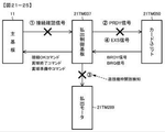
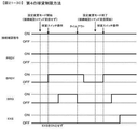
有価価値(プリペイド残額、持玉、貯玉等)に関する処理(プリペイド残額を消費する球貸、持玉を消費する球貸、貯玉を消費する球貸等に関連した処理)を実行可能な遊技用装置(カードユニット21TM050)から出力される信号(VL信号、BRDY信号、BRQ信号等)を受信可能な遊技機(パチンコ遊技機1)であって、
前記遊技用装置から出力される信号に基づいて遊技媒体を付与する付与手段(払出モータ21TM289を制御する払出制御用マイクロコンピュータ21TM370)と、
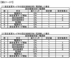
設定値(大当り判定用乱数の範囲が異なる設定値1〜6)に応じた特定制御(特別図柄プロセス処理における大当り判定処理等)を実行可能な特定制御手段(ステップS21TM1690等の処理を実行する遊技制御用マイクロコンピュータ100)と、
前記設定値を変更可能な設定変更モードに制御可能な設定変更モード制御手段(ステップS21TM1130〜ステップS21TM1200を実行可能な遊技制御用マイクロコンピュータ100)と、
を備え、
前記設定変更モードに制御されているときに、前記遊技用装置から出力される信号に基づく遊技媒体の付与が制限される(1.設定変更モードに制御されているときに遊技制御用マイクロコンピュータ100が接続確認信号をオンとしない(払出制御基板21TM037に出力しない)、2.設定変更モードに制御されているときに遊技制御用マイクロコンピュータ100が接続確認コマンドを送信しないことにより、払出制御用マイクロコンピュータ21TM370がPRDY信号をオンとしない、3.遊技機枠開放センサにより遊技機用枠3が開放状態となっていることを検出しているときには、払出制御用マイクロコンピュータ21TM370がPRDY信号をオンとしない、4.設定変更モードに制御されているときに遊技制御用マイクロコンピュータ100が接続確認コマンドを送信しないことにより(払出制御用マイクロコンピュータ21TM370が接続確認コマンドを受信しないことにより)、払出制御用マイクロコンピュータ21TM370がBRQ信号のオンを検出しても、EXS信号をオンとしない。)
ことを特徴とする。
これによれば、設定変更モードに制御されているときに、遊技媒体の付与に関して適切な制御を実行可能である。
例えば、図21−12及び図21−13に示すように、電源スイッチ21TM055が操作されて動作電圧が主基板11に供給されたときに、遊技制御用マイクロコンピュータ100は、錠スイッチ21TM051がON状態であり、且つ、クリアスイッチ(設定切替スイッチ)21TM052がON状態であることに基づいて、設定値を変更可能な設定変更モードに制御する。設定変更モードに制御されている期間は、ステップS21TM1480のシリアル通信回路設定処理が実行されていないことにより、接続確認信号が払出制御基板21TM037に出力されておらず、払出制御用マイクロコンピュータ21TM370は、球貸を実行しない。
The gaming machine of means A1
A gaming device capable of performing processing related to valuable value (prepaid balance, balls, balls, etc.) (processing related to ball lending that consumes the prepaid balance, ball lending that consumes the balls, ball lending that consumes the balls, etc.) A gaming machine (pachinko gaming machine 1) capable of receiving signals (VL signal, BRDY signal, BRQ signal, etc.) output from (card unit 21TM050).
The granting means (payout control microcomputer 21TM370 that controls the payout motor 21TM289) that grants the game medium based on the signal output from the game device, and
A game that executes a process such as step S21TM1690 that can execute specific control (big hit determination process in special symbol process processing, etc.) according to a set value (set
A setting change mode control means (a
With
When the setting change mode is controlled, the addition of the game medium based on the signal output from the game device is restricted (1. The
It is characterized by that.
According to this, when it is controlled to the setting change mode, it is possible to execute appropriate control regarding the addition of the game medium.
For example, as shown in FIGS. 21-12 and 21-13, when the power switch 21TM055 is operated and the operating voltage is supplied to the
手段A2の遊技機は、
手段A1の遊技機であって、
前記特定制御手段と前記設定変更モード制御手段とを有し、前記遊技機における遊技の進行を制御する遊技制御手段(遊技制御用タイマ割込処理を実行する遊技制御用マイクロコンピュータ100)を備え、
前記遊技制御手段は、前記設定値を確認可能な設定確認モードに制御可能な設定確認モード制御手段(ステップS21TM1210〜ステップS21TM1240を実行可能な遊技制御用マイクロコンピュータ100)を有し、
前記付与手段(払出制御用マイクロコンピュータ21TM370)は、前記遊技制御手段から特別信号(接続確認信号)が入力されたときに遊技媒体の付与が可能であり、
前記遊技制御手段は、前記設定変更モード及び前記設定確認モードの何れかに制御されているときには、前記特別信号を出力しない(接続確認信号を出力するステップS21TM1480のシリアル通信回路設定処理は、設定変更モードの終了後、設定確認モードの終了後、に実行される)、
ことを特徴とする。
これによれば、設定変更モード及び設定確認モードの何れかに制御されているときに、遊技媒体を付与しないようにすることができる。
The gaming machine of means A2 is
It is a gaming machine of means A1 and
A game control means (a
The game control means has a setting confirmation mode control means (a
The granting means (microcomputer 21TM370 for payout control) can grant a game medium when a special signal (connection confirmation signal) is input from the game control means.
When the game control means is controlled by either the setting change mode or the setting confirmation mode, the game control means does not output the special signal (the serial communication circuit setting process in step S21TM1480 for outputting the connection confirmation signal changes the setting. Executed after the mode ends, after the setting confirmation mode ends),
It is characterized by that.
According to this, it is possible not to give the game medium when controlled by either the setting change mode or the setting confirmation mode.
手段A3の遊技機は、
手段A1の遊技機であって、
前記設定値を確認可能な設定確認モードに制御可能な設定確認モード制御手段(ステップS21TM1210〜ステップS21TM1240を実行可能な遊技制御用マイクロコンピュータ100)を備え、
前記付与手段(払出制御用マイクロコンピュータ21TM370)は、前記遊技用装置に対して第1所定信号(PRDY信号)を出力し、前記第1所定信号が入力されていることに基づいて前記遊技用装置から出力される第2所定信号(BRDY信号)が入力されたことに基づいて遊技媒体の付与が可能であり、
前記設定変更モード及び前記設定確認モードの何れかに制御されているときには、前記第1所定信号を出力しない(1.接続確認信号が入力されていないときにはPRDY信号をオンとしない、2.接続確認コマンドを受信していないときにはPRDY信号をオンとしない)、
ことを特徴とする。
これによれば、設定変更モード及び設定確認モードの何れかに制御されているときに、遊技媒体を付与しないようにすることができる。
The gaming machine of means A3 is
It is a gaming machine of means A1 and
A setting confirmation mode control means (a
The granting means (payout control microcomputer 21TM370) outputs a first predetermined signal (PRDY signal) to the gaming device, and the gaming device is based on the input of the first predetermined signal. It is possible to add a game medium based on the input of the second predetermined signal (BRDY signal) output from.
When controlled by either the setting change mode or the setting confirmation mode, the first predetermined signal is not output (1. When the connection confirmation signal is not input, the PRDY signal is not turned on. 2. Connection confirmation. Do not turn on the PRDY signal when no command is received),
It is characterized by that.
According to this, it is possible not to give the game medium when controlled by either the setting change mode or the setting confirmation mode.
手段A4の遊技機は、
手段A1の遊技機であって、
前記特定制御手段と前記設定変更モード制御手段とを有し、前記遊技機における遊技の進行を制御する遊技制御手段(遊技制御用タイマ割込処理を実行する遊技制御用マイクロコンピュータ100)を備え、
前記遊技制御手段及び前記付与手段の少なくとも一方(例えば、払出制御用マイクロコンピュータ21TM370)には、当該遊技機に対応した遊技機枠又は扉枠が開放された開放状態を検出する開放状態検出手段(遊技機用枠3が開放状態となっていることを検出可能な遊技機枠開放センサ、ガラス扉枠3aが開放状態となっていることを検出可能な扉枠開放センサを備えた遊技機枠・扉枠開放センサ21TM300)が設けられ、
前記設定変更モードに制御されているか否かによらず、前記開放状態が検出されているときには遊技媒体の付与を制限する(遊技機用枠3が開放状態となっているとき、ガラス扉枠3aが開放状態となっているときにはPRDY信号をオンとしない)、
ことを特徴とする。
これによれば、設定変更モードに制御させるために遊技機枠又は扉枠を開放させる場合に、遊技媒体の付与を制限することができる。
The gaming machine of means A4 is
It is a gaming machine of means A1 and
A game control means (a
At least one of the game control means and the granting means (for example, the payout control microcomputer 21TM370) has an open state detecting means (for example, an open state detecting means for detecting an open state in which the game machine frame or the door frame corresponding to the game machine is opened. A gaming machine frame equipped with a gaming machine frame opening sensor that can detect that the
Regardless of whether or not the setting change mode is controlled, when the open state is detected, the addition of the gaming medium is restricted (when the
It is characterized by that.
According to this, when the gaming machine frame or the door frame is opened in order to control the setting change mode, it is possible to limit the addition of the gaming medium.
手段A5の遊技機は、
手段A1〜手段A4から選択される何れかの遊技機であって、
前記設定値を確認可能な設定確認モードに制御可能な設定確認モード制御手段(ステップS21TM1210〜ステップS21TM1240を実行可能な遊技制御用マイクロコンピュータ100)を備え、
前記付与手段は、前記遊技用装置から付与要求信号が入力されたこと(BRQ信号がオンとされたこと)に応じて付与準備信号を出力し(EXS信号をオンとし)、前記付与準備信号の入力に応じて前記遊技用装置から出力される付与指令信号が入力されたとき(EXS信号のオンを検出したカードユニット21TM050がBRQ信号をオフとしたとき)に遊技媒体を付与し、
前記設定変更モード及び前記設定確認モードの何れかに制御されているときには、前記付与要求信号が入力されても前記付与準備信号を出力しない(BRQ信号のオンを検出してもEXS信号をオンとしない)、
ことを特徴とする。
これによれば、設定変更モード及び設定確認モードの何れかに制御されているときに、遊技媒体を付与しないようにすることができる。
The gaming machine of means A5 is
Any gaming machine selected from means A1 to means A4.
A setting confirmation mode control means (a
The granting means outputs a grant preparation signal (turns on the EXS signal) in response to the input of the grant request signal from the game device (the BRQ signal is turned on), and the grant preparation signal of the grant preparation signal. When the grant command signal output from the gaming device is input in response to the input (when the card unit 21TM050 that detects the ON of the EXS signal turns off the BRQ signal), the gaming medium is fed.
When controlled by either the setting change mode or the setting confirmation mode, the grant preparation signal is not output even if the grant request signal is input (the EXE signal is turned on even if the BRQ signal is detected to be on). do not),
It is characterized by that.
According to this, it is possible not to give the game medium when controlled by either the setting change mode or the setting confirmation mode.
手段A6の遊技機は、
手段A1〜手段A5から選択される何れかの遊技機であって、
前記設定値を確認可能な設定確認モードに制御可能な設定確認モード制御手段(ステップS21TM1210〜ステップS21TM1240を実行可能な遊技制御用マイクロコンピュータ100)を備え、
前記設定変更モード制御手段は、当該遊技機への電力供給が開始されたときに設定変更条件が成立している場合(電源投入時に錠スイッチ21TM051がオンであり、且つ、クリアスイッチ(設定切替スイッチ)21TM052がオンである場合)に、前記設定変更モードに制御し、
前記設定確認モード制御手段は、当該遊技機への電力供給が開始されたときに設定確認条件が成立している場合(電源投入時に錠スイッチ21TM051がオンであり、且つ、クリアスイッチ(設定切替スイッチ)21TM052がオフである場合)に、前記設定確認モードに制御する、
ことを特徴とする。
これによれば、遊技機への電力供給が開始されたときに設定変更モード又は設定確認モードに制御可能である。
The gaming machine of means A6 is
Any gaming machine selected from means A1 to means A5.
A setting confirmation mode control means (a
The setting change mode control means is used when the setting change condition is satisfied when the power supply to the gaming machine is started (the lock switch 21TM051 is on when the power is turned on, and the clear switch (setting changeover switch). ) When 21TM052 is on), control to the above setting change mode,
The setting confirmation mode control means is used when the setting confirmation condition is satisfied when the power supply to the gaming machine is started (the lock switch 21TM051 is turned on when the power is turned on, and the clear switch (setting changeover switch). ) When 21TM052 is off), the setting confirmation mode is controlled.
It is characterized by that.
According to this, it is possible to control the setting change mode or the setting confirmation mode when the power supply to the gaming machine is started.
手段A7の遊技機は、
手段A1〜手段A6から選択される何れかの遊技機であって、
前記設定変更モードに制御されたときには、遊技状態が初期化され(ステップS21TM1410のRAMクリアが実行され)、
前記設定変更モードの制御の終了に基づいて、前記設定変更モードの制御の終了に対応する報知を実行した後に(表示モニタ21TM029に設定値を点滅表示させた後に)、遊技状態が初期化されたことを報知する(表示モニタ21TM029に「C」の文字を表示させる)、
ことを特徴とする。
これによれば、遊技場の店員等が、設定変更モードの制御が終了して遊技状態が初期化されたことを把握することができる。
The gaming machine of means A7 is
Any gaming machine selected from means A1 to means A6.
When controlled to the setting change mode, the game state is initialized (RAM clear in step S21TM1410 is executed), and the game state is executed.
Based on the end of the control of the setting change mode, the gaming state is initialized after executing the notification corresponding to the end of the control of the setting change mode (after blinking the set value on the display monitor 21TM029). Notify that (display the character "C" on the display monitor 21TM029),
It is characterized by that.
According to this, the store clerk of the game hall can grasp that the control of the setting change mode is finished and the game state is initialized.
手段A8の遊技機は、
手段A1〜手段A7から選択される何れかの遊技機であって、
前記特定制御手段と前記設定変更モード制御手段とを有し、前記遊技機における遊技の進行を制御する遊技制御手段(遊技制御用タイマ割込処理を実行する遊技制御用マイクロコンピュータ100)と、
演出の実行を制御する演出制御手段(演出制御用CPU120)と、を備え、
前記遊技制御手段は、前記設定値を確認可能な設定確認モードに制御可能な設定確認モード制御手段(ステップS21TM1210〜ステップS21TM1240を実行可能な遊技制御用マイクロコンピュータ100)を更に有し、
前記遊技制御手段は、前記設定変更モード又は前記設定確認モードの何れかに制御されることに伴い、前記演出制御手段に対してコマンド(設定変更モードコマンド、設定確認モードコマンド)を出力し、
前記演出制御手段は、前記コマンドに応じた報知に関する制御を実行する(設定変更モードコマンドを受信したときに画像表示装置5に「設定変更中」と表示する、設定確認モードコマンドを受信したときに画像表示装置5に「設定確認中」と表示する)、
ことを特徴とする。
これによれば、遊技場の店員等が、設定変更モード又は設定確認モードに制御されたことを把握することができる。
The gaming machine of means A8 is
Any gaming machine selected from means A1 to means A7.
A game control means (a
It is equipped with an effect control means (
The game control means further includes a setting confirmation mode control means (a
The game control means outputs commands (setting change mode command, setting confirmation mode command) to the effect control means as it is controlled by either the setting change mode or the setting confirmation mode.
The effect control means executes control related to notification according to the command (when receiving a setting confirmation mode command that displays "setting change in progress" on the
It is characterized by that.
According to this, it can be grasped that the clerk of the amusement park or the like is controlled to the setting change mode or the setting confirmation mode.
手段A9の遊技機は、
手段A1〜手段A8から選択される何れかの遊技機であって、
前記設定値を確認可能な設定確認モードに制御可能な設定確認モード制御手段(ステップS21TM1210〜ステップS21TM1240を実行可能な遊技制御用マイクロコンピュータ100)を備え、
前記設定変更モード制御手段は、移行操作(電源投入時に錠スイッチ21TM051をONとする操作)及び初期化操作(電源投入時にクリアスイッチ21TM052をONとする操作)に基づいて前記設定変更モードに制御し、
前記設定確認モード制御手段は、前記移行操作(電源投入時に錠スイッチ21TM051をONとする操作)に基づいて前記設定確認モードに制御し、
前記設定変更モードに制御されることに伴い、当該遊技機の遊技状態が初期化され(設定変更モードに制御された場合には、ステップS21TM1410のRAMクリア処理が実行され)、前記設定確認モードに制御されることに伴い、当該遊技機の遊技状態が初期化されない(設定確認モードに制御された場合には、ステップS21TM1320又はステップS21TM1330でNOと判定された場合にのみ、ステップS21TM1410のRAMクリア処理が実行される)、
ことを特徴とする。
これによれば、遊技場の店員等が、設定変更モード及び設定確認モードの何れに制御させるかを選択可能であると共に、遊技状態を初期化させるか否かも選択可能となる。
The gaming machine of means A9 is
Any gaming machine selected from means A1 to means A8.
A setting confirmation mode control means (a
The setting change mode control means controls the setting change mode based on a transition operation (an operation of turning on the lock switch 21TM051 when the power is turned on) and an initialization operation (an operation of turning on the clear switch 21TM052 when the power is turned on). ,
The setting confirmation mode control means controls the setting confirmation mode based on the transition operation (the operation of turning on the lock switch 21TM051 when the power is turned on).
Along with being controlled to the setting change mode, the gaming state of the gaming machine is initialized (when controlled to the setting change mode, the RAM clear process of step S21TM1410 is executed), and the setting confirmation mode is set. Due to the control, the gaming state of the gaming machine is not initialized (when controlled to the setting confirmation mode, the RAM clear processing in step S21TM1410 is performed only when NO is determined in step S21TM1320 or step S21TM1330. Is executed),
It is characterized by that.
According to this, the store clerk of the game hall can select whether to control the setting change mode or the setting confirmation mode, and also can select whether to initialize the game state.
また、特開2010−200902号公報(段落0007)に示すように、複数段階の設定値を外部からの設定変更操作に基づいて変更する設定変更手段を備える遊技機が提案されている。特開2010−200902号公報(段落0007)に記載されたような遊技機では、設定値を変更するときに、遊技用装置から出力される信号に基づく制御を適切に実行する必要がある。手段B1〜手段B7に係る発明は、上記の実状に鑑みてなされたものであり、遊技用装置から出力される信号に基づく制御を適切に実行する遊技機を提供することにある。 Further, as shown in Japanese Patent Application Laid-Open No. 2010-200902 (paragraph 0007), a gaming machine including a setting changing means for changing a setting value in a plurality of stages based on a setting changing operation from the outside has been proposed. In a gaming machine as described in Japanese Patent Application Laid-Open No. 2010-200902 (paragraph 0007), when changing a set value, it is necessary to appropriately execute control based on a signal output from the gaming device. The invention according to the means B1 to the means B7 has been made in view of the above-mentioned actual conditions, and an object of the present invention is to provide a gaming machine that appropriately executes control based on a signal output from a gaming device.
手段B1の遊技機は、
有価価値(プリペイド残額、持玉、貯玉等)に関する処理(プリペイド残額を消費する球貸、持玉を消費する球貸、貯玉を消費する球貸等に関連した処理)を実行可能な遊技用装置(カードユニット21TM050)から出力される信号(VL信号、BRDY信号、BRQ信号等)を受信可能な遊技機(パチンコ遊技機1)であって、
前記遊技用装置から出力される信号に基づいて所定制御(球貸)を実行する所定制御手段(払出モータ21TM289を制御する払出制御用マイクロコンピュータ21TM370)と、
設定値(大当り判定用乱数の範囲が異なる設定値1〜6)に応じた特定制御(特別図柄プロセス処理における大当り判定処理等)を実行可能な特定制御手段(ステップS21TM1690等の処理を実行する遊技制御用マイクロコンピュータ100)と、
前記設定値を変更可能な設定変更モードに制御可能な設定変更モード制御手段(ステップS21TM1130〜ステップS21TM1200を実行可能な遊技制御用マイクロコンピュータ100)と、を備え、
前記設定変更モードに制御されているか否かにかかわらず、前記遊技用装置から出力される信号に基づく所定制御を実行可能である(遊技制御用マイクロコンピュータ100は、設定変更モードに制御されている期間であっても、接続確認信号をON状態とし、接続確認コマンド及び賞球個数コマンドを送信可能であり、接続確認信号のON状態で、接続確認コマンド及び賞球個数コマンドを受信した払出制御用マイクロコンピュータ21TM370は、設定変更モードに制御されている期間であるか否かにかかわらず球貸を実行可能である)、
ことを特徴とする。
これによれば、遊技用装置から出力される信号に基づく所定制御を適切に実行可能であり、設定変更モードに制御されているときに所定制御を実行しない場合の制御負担を回避することができる。
The gaming machine of means B1
A gaming device capable of performing processing related to valuable value (prepaid balance, balls, balls, etc.) (processing related to ball lending that consumes the prepaid balance, ball lending that consumes the balls, ball lending that consumes the balls, etc.) A gaming machine (pachinko gaming machine 1) capable of receiving signals (VL signal, BRDY signal, BRQ signal, etc.) output from (card unit 21TM050).
A predetermined control means (payout control microcomputer 21TM370 that controls the payout motor 21TM289) that executes a predetermined control (ball lending) based on a signal output from the game device, and
A game that executes a process such as step S21TM1690 that can execute specific control (big hit determination process in special symbol process processing, etc.) according to a set value (set
A setting change mode control means (a
Regardless of whether or not the setting change mode is controlled, predetermined control based on the signal output from the game device can be executed (the
It is characterized by that.
According to this, the predetermined control based on the signal output from the gaming device can be appropriately executed, and the control burden when the predetermined control is not executed while being controlled in the setting change mode can be avoided. ..
手段B2の遊技機は、
手段B1の遊技機であって、
前記設定値を確認可能な設定確認モードに制御可能な設定確認モード制御手段(ステップS21TM1210〜ステップS21TM1240を実行可能な遊技制御用マイクロコンピュータ100)を備え、
前記所定制御を実行しているときに所定事象(電源断等)が発生したことに基づいて当該所定制御を中断し、その後に前記設定変更モード又は前記設定確認モードに制御されたときには、前記設定変更モード又は前記設定確認モードの終了後に、当該所定制御を再開する(払出制御用マイクロコンピュータ21TM370は、球貸の実行途中で電源断が発生した場合には球貸を中断し、電力供給再開後に遊技制御用マイクロコンピュータ100が設定変更モード又は設定確認モードに移行した場合には、直ちに球貸を再開することなく当該設定変更モード又は当該設定確認モードの終了後に球貸を再開する)、
ことを特徴とする。
これによれば、所定事象が発生した後に設定変更モード又は設定確認モードに制御されたときにも、所定制御を適切に実行可能である。
The gaming machine of means B2 is
It is a gaming machine of means B1 and
A setting confirmation mode control means (a
When the predetermined control is interrupted based on the occurrence of a predetermined event (power failure, etc.) while the predetermined control is being executed, and then the predetermined control is controlled to the setting change mode or the setting confirmation mode, the setting is performed. After the change mode or the setting confirmation mode ends, the predetermined control is restarted (the payout control microcomputer 21TM370 interrupts the ball lending if the power is cut off during the execution of the ball lending, and after the power supply is restarted. When the
It is characterized by that.
According to this, even when the setting change mode or the setting confirmation mode is controlled after the predetermined event occurs, the predetermined control can be appropriately executed.
手段B3の遊技機は、
手段B1の遊技機であって、
前記設定値を確認可能な設定確認モードに制御可能な設定確認モード制御手段(ステップS21TM1210〜ステップS21TM1240を実行可能な遊技制御用マイクロコンピュータ100)を備え、
前記所定制御を実行しているときに、前記設定変更モード又は前記設定確認モードに制御されたときには、当該所定制御を終了させる(払出制御用マイクロコンピュータ21TM370は、球貸の実行中に電源断が発生したときには、当該球貸を強制終了させ(中止し)、その後の電源復旧時に遊技制御用マイクロコンピュータ100が設定変更モード又は設定確認モードに制御されたときに球貸は再開されず、設定変更モード又は設定確認モードの終了後も球貸は再開されない)、
ことを特徴とする。
これによれば、設定変更モード又は設定確認モードの終了後に所定制御を再開させる制御が不要となり、所定制御を簡略化することができる。
The gaming machine of means B3 is
It is a gaming machine of means B1 and
A setting confirmation mode control means (a
When the predetermined control is being executed and the setting change mode or the setting confirmation mode is controlled, the predetermined control is terminated (the payout control microcomputer 21TM370 is powered off during the execution of ball lending. When it occurs, the ball lending is forcibly terminated (cancelled), and when the
It is characterized by that.
According to this, the control for restarting the predetermined control after the end of the setting change mode or the setting confirmation mode becomes unnecessary, and the predetermined control can be simplified.
手段B4の遊技機は、
手段B1〜手段B3から選択される何れかの遊技機であって、
前記設定値を確認可能な設定確認モードに制御可能な設定確認モード制御手段(ステップS21TM1210〜ステップS21TM1240を実行可能な遊技制御用マイクロコンピュータ100)を備え、
前記設定変更モード制御手段は、当該遊技機への電力供給が開始されたときに設定変更条件が成立している場合(錠スイッチ21TM051がON状態であり、且つ、クリアスイッチ21TM052もON状態である場合)に、前記設定変更モードに制御し、
前記設定確認モード制御手段は、当該遊技機への電力供給が開始されたときに設定確認条件が成立している場合(錠スイッチ21TM051がON状態であり、且つ、クリアスイッチ21TM052はOFF状態である場合)に、前記設定確認モードに制御する、
ことを特徴とする。
これによれば、遊技機への電力供給が開始されたときに成立している条件に応じて、設定変更モード又は設定確認モードに制御することができる。
The gaming machine of means B4 is
Any gaming machine selected from means B1 to means B3.
A setting confirmation mode control means (a
The setting change mode control means is in the case where the setting change condition is satisfied when the power supply to the gaming machine is started (the lock switch 21TM051 is in the ON state, and the clear switch 21TM052 is also in the ON state. If), control to the above setting change mode,
When the setting confirmation condition is satisfied when the power supply to the gaming machine is started (the lock switch 21TM051 is in the ON state and the clear switch 21TM052 is in the OFF state), the setting confirmation mode control means is in the OFF state. In the case of), control to the above setting confirmation mode,
It is characterized by that.
According to this, it is possible to control the setting change mode or the setting confirmation mode according to the conditions that are satisfied when the power supply to the gaming machine is started.
手段B5の遊技機は、
手段B1〜手段B4から選択される何れかの遊技機であって、
前記設定変更モードに制御されたときには、遊技情報が初期化され(設定変更モードに制御されたときには、ステップS21TM1410のRAMクリアが実行され)、
前記設定変更モードにおいて前記設定値が変更されたときには、設定値の変更を報知した後に(表示モニタ21TM029に設定値を点滅表示させた後に)、遊技状態が初期化されたことを報知する(表示モニタ21TM029に「C」の文字を表示させる)、
ことを特徴とする。
これによれば、遊技場の店員等が、設定変更モードの制御が終了して遊技状態が初期化されたことを把握することができる。
The gaming machine of means B5 is
Any gaming machine selected from means B1 to means B4.
When controlled to the setting change mode, the game information is initialized (when controlled to the setting change mode, RAM clear in step S21TM1410 is executed).
When the set value is changed in the setting change mode, after notifying the change of the set value (after blinking the set value on the display monitor 21TM029), it notifies that the game state has been initialized (display). Display the letter "C" on monitor 21TM029),
It is characterized by that.
According to this, the store clerk of the game hall can grasp that the control of the setting change mode is finished and the game state is initialized.
手段B6の遊技機は、
手段B1〜手段B5から選択される何れかの遊技機であって、
前記特定制御手段と前記設定変更モード制御手段とを有し、前記遊技機における遊技の進行を制御する遊技制御手段(遊技制御用タイマ割込処理を実行する遊技制御用マイクロコンピュータ100)と、
演出の実行を制御する演出制御手段(演出制御用CPU120)と、を備え、
前記遊技制御手段は、前記設定値を確認可能な設定確認モードに制御可能な設定確認モード制御手段(ステップS21TM1210〜ステップS21TM1240を実行可能な遊技制御用マイクロコンピュータ100)を更に有し、
前記遊技制御手段は、前記設定変更モード又は前記設定確認モードの何れかに制御されることに伴い、前記演出制御手段に対してコマンド(設定変更モードコマンド、設定確認モードコマンド)を出力し、
前記演出制御手段は、前記コマンドに応じた報知に関する制御を実行する(設定変更モードコマンドを受信したときに画像表示装置5に「設定変更中」と表示する、設定確認モードコマンドを受信したときに画像表示装置5に「設定確認中」と表示する)、
ことを特徴とする。
これによれば、遊技場の店員等が、設定変更モード又は設定確認モードに制御されたことを把握することができる。
The gaming machine of means B6 is
Any gaming machine selected from means B1 to means B5.
A game control means (a
It is equipped with an effect control means (
The game control means further includes a setting confirmation mode control means (a
The game control means outputs commands (setting change mode command, setting confirmation mode command) to the effect control means as it is controlled by either the setting change mode or the setting confirmation mode.
The effect control means executes control related to notification according to the command (when receiving a setting confirmation mode command that displays "setting change in progress" on the
It is characterized by that.
According to this, it can be grasped that the clerk of the amusement park or the like is controlled to the setting change mode or the setting confirmation mode.
手段B7の遊技機は、
手段B1〜手段B6から選択される何れかの遊技機であって、
前記設定値を確認可能な設定確認モードに制御可能な設定確認モード制御手段(ステップS21TM1210〜ステップS21TM1240を実行可能な遊技制御用マイクロコンピュータ100)を備え、
前記設定変更モード制御手段は、移行操作(電源投入時に錠スイッチ21TM051をONとする操作)及び初期化操作(電源投入時にクリアスイッチ21TM052をONとする操作)に基づいて前記設定変更モードに制御し、
前記設定確認モード制御手段は、前記移行操作(電源投入時に錠スイッチ21TM051をONとする操作)に基づいて前記設定確認モードに制御し、
前記設定変更モードに制御されることに伴い、当該遊技機の遊技状態が初期化され(設定変更モードに制御された場合には、ステップS21TM1410のRAMクリア処理が実行され)、前記設定確認モードに制御されることに伴い、当該遊技機の遊技状態が初期化されない(設定確認モードに制御された場合には、ステップS21TM1320又はステップS21TM1330でNOと判定された場合にのみ、ステップS21TM1410のRAMクリア処理が実行される)、
ことを特徴とする。
これによれば、遊技場の店員等が、設定変更モード及び設定確認モードの何れに制御させるかを選択可能であると共に、遊技状態を初期化させるか否かも選択可能となる。
The gaming machine of means B7 is
Any gaming machine selected from means B1 to means B6.
A setting confirmation mode control means (a
The setting change mode control means controls the setting change mode based on a transition operation (an operation of turning on the lock switch 21TM051 when the power is turned on) and an initialization operation (an operation of turning on the clear switch 21TM052 when the power is turned on). ,
The setting confirmation mode control means controls the setting confirmation mode based on the transition operation (the operation of turning on the lock switch 21TM051 when the power is turned on).
Along with being controlled to the setting change mode, the gaming state of the gaming machine is initialized (when controlled to the setting change mode, the RAM clear process of step S21TM1410 is executed), and the setting confirmation mode is set. Due to the control, the gaming state of the gaming machine is not initialized (when controlled to the setting confirmation mode, the RAM clear processing in step S21TM1410 is performed only when NO is determined in step S21TM1320 or step S21TM1330. Is executed),
It is characterized by that.
According to this, the store clerk of the game hall can select whether to control the setting change mode or the setting confirmation mode, and also can select whether to initialize the game state.
また、特開2010−200902号公報(段落0007)に示すように、複数段階の設定値を外部からの設定変更操作に基づいて変更する設定変更手段を備える遊技機が提案されている。特開2010−200902号公報(段落0007)に記載されたような遊技機では、設定値を変更するときに、遊技媒体が特定領域を通過した場合の制御を適切に実行する必要がある。手段C1〜手段C6に係る発明は、上記の実状に鑑みてなされたものであり、遊技媒体が特定領域を通過した場合の制御を適切に実行する遊技機を提供することにある。 Further, as shown in Japanese Patent Application Laid-Open No. 2010-200902 (paragraph 0007), a gaming machine including a setting changing means for changing a setting value in a plurality of stages based on a setting changing operation from the outside has been proposed. In a gaming machine as described in Japanese Patent Application Laid-Open No. 2010-200902 (paragraph 0007), when changing a set value, it is necessary to appropriately perform control when the gaming medium passes through a specific region. The invention according to the means C1 to the means C6 has been made in view of the above-mentioned actual conditions, and an object of the present invention is to provide a gaming machine that appropriately executes control when a gaming medium passes through a specific region.
手段C1の遊技機は、
遊技媒体が特定領域(第1始動入賞口、第2始動入賞口)を通過したことに基づいて、設定値(大当り判定用乱数の範囲が異なる設定値1〜6)に応じた特定制御(特別図柄プロセス処理における大当り判定処理等)を実行可能な特定制御手段(ステップS21TM1690等の処理を実行する遊技制御用マイクロコンピュータ100)と、
前記設定値を変更可能な設定変更モードに制御可能な設定変更モード制御手段(ステップS21TM1130〜ステップS21TM1200を実行可能な遊技制御用マイクロコンピュータ100)と、を備え、
前記設定変更モードに制御されているときには、遊技媒体が前記特定領域を通過しても前記特定制御が実行されない(タイマ割込の設定(ステップS21TM1500)よりも前に設定変更モードに制御されることにより、設定変更モードに制御されている期間は、ステップS21TM1690の特別図柄プロセス処理(大当り判定処理)が実行されない)、
ことを特徴とする。
これによれば、設定値が変更される可能性があるときに特定制御が実行されてしまうことを防止することができる。
The gaming machine of means C1
Specific control (special) according to set values (set
A setting change mode control means (a
When controlled to the setting change mode, the specific control is not executed even if the game medium passes through the specific area (the setting change mode is controlled before the timer interrupt setting (step S21TM1500)). Therefore, during the period controlled to the setting change mode, the special symbol process process (big hit determination process) of step S21TM1690 is not executed),
It is characterized by that.
According to this, it is possible to prevent the specific control from being executed when the set value may be changed.
手段C2の遊技機は、
手段C1の遊技機であって、
前記設定値を確認可能な設定確認モードに制御可能な設定確認モード制御手段(ステップS21TM1210〜ステップS21TM1240を実行可能な遊技制御用マイクロコンピュータ100)を備え、
前記設定変更モード制御手段は、当該遊技機への電力供給が開始されたときに設定変更条件が成立している場合(錠スイッチ21TM051がON状態であり、且つ、クリアスイッチ21TM052もON状態である場合)に、前記設定変更モードに制御し、
前記設定確認モード制御手段は、当該遊技機への電力供給が開始されたときに設定確認条件が成立している場合(錠スイッチ21TM051がON状態であり、且つ、クリアスイッチ21TM052はOFF状態である場合)に、前記設定確認モードに制御する、
ことを特徴とする。
これによれば、遊技機への電力供給が開始されたときに成立している条件に応じて、設定変更モード又は設定確認モードに制御することができる。
The gaming machine of means C2 is
Means C1 gaming machine
A setting confirmation mode control means (a
The setting change mode control means is in the case where the setting change condition is satisfied when the power supply to the gaming machine is started (the lock switch 21TM051 is in the ON state, and the clear switch 21TM052 is also in the ON state. If), control to the above setting change mode,
When the setting confirmation condition is satisfied when the power supply to the gaming machine is started (the lock switch 21TM051 is in the ON state and the clear switch 21TM052 is in the OFF state), the setting confirmation mode control means is in the OFF state. In the case of), control to the above setting confirmation mode,
It is characterized by that.
According to this, it is possible to control the setting change mode or the setting confirmation mode according to the conditions that are satisfied when the power supply to the gaming machine is started.
手段C3の遊技機は、
手段C1又は手段C2の遊技機であって、
前記設定変更モードに制御されたときには、遊技状態が初期化され(設定変更モードに制御されたときには、ステップS21TM1410のRAMクリアが実行され)、
前記設定変更モードの制御の終了に基づいて、前記設定変更モードの制御の終了に対応する報知を実行した後に(表示モニタ21TM029に設定値を点滅表示させた後に)、遊技状態が初期化されたことを報知する(表示モニタ21TM029に「C」の文字を表示させる)、
ことを特徴とする。
これによれば、遊技場の店員等が、設定変更モードの制御が終了して遊技状態が初期化されたことを把握することができる。
The gaming machine of means C3 is
A gaming machine of means C1 or means C2.
When controlled to the setting change mode, the gaming state is initialized (when controlled to the setting change mode, RAM clear in step S21TM1410 is executed).
Based on the end of the control of the setting change mode, the gaming state is initialized after executing the notification corresponding to the end of the control of the setting change mode (after blinking the set value on the display monitor 21TM029). Notify that (display the character "C" on the display monitor 21TM029),
It is characterized by that.
According to this, the store clerk of the game hall can grasp that the control of the setting change mode is finished and the game state is initialized.
手段C4の遊技機は、
手段C1〜手段C3から選択される何れかの遊技機であって、
前記特定制御手段と前記設定変更モード制御手段とを有し、前記遊技機における遊技の進行を制御する遊技制御手段(遊技制御用タイマ割込処理を実行する遊技制御用マイクロコンピュータ100)と、
演出の実行を制御する演出制御手段(演出制御用CPU120)と、を備え、
前記遊技制御手段は、前記設定値を確認可能な設定確認モードに制御可能な設定確認モード制御手段(ステップS21TM1210〜ステップS21TM1240を実行可能な遊技制御用マイクロコンピュータ100)を更に有し、
前記遊技制御手段は、前記設定変更モード又は前記設定確認モードの何れかに制御されることに伴い、前記演出制御手段に対してコマンド(設定変更モードコマンド、設定確認モードコマンド)を出力し、
前記演出制御手段は、前記コマンドに応じた報知に関する制御を実行する(設定変更モードコマンドを受信したときに画像表示装置5に「設定変更中」と表示する、設定確認モードコマンドを受信したときに画像表示装置5に「設定確認中」と表示する)、
ことを特徴とする。
これによれば、遊技場の店員等が、設定変更モード又は設定確認モードに制御されたことを把握することができる。
The game machine of means C4
Any gaming machine selected from means C1 to means C3.
A game control means (a
It is equipped with an effect control means (
The game control means further includes a setting confirmation mode control means (a
The game control means outputs commands (setting change mode command, setting confirmation mode command) to the effect control means as it is controlled by either the setting change mode or the setting confirmation mode.
The effect control means executes control related to notification according to the command (when receiving a setting confirmation mode command that displays "setting change in progress" on the
It is characterized by that.
According to this, it can be grasped that the clerk of the amusement park or the like is controlled to the setting change mode or the setting confirmation mode.
手段C5の遊技機は、
手段C1〜手段C4から選択される何れかの遊技機であって、
前記設定値を確認可能な設定確認モードに制御可能な設定確認モード制御手段(ステップS21TM1210〜ステップS21TM1240を実行可能な遊技制御用マイクロコンピュータ100)を備え、
前記設定確認モードに制御されているときには、遊技媒体が前記特定領域を通過しても前記特定制御を実行しない(タイマ割込の設定(ステップS21TM1500)よりも前に設定確認モードに制御されることにより、設定確認モードに制御されている期間は、ステップS21TM1690の特別図柄プロセス処理(大当り判定処理)が実行されない)、
ことを特徴とする。
これによれば、設定値が確認されているときに特定制御が実行されてしまうことを防止することができる。
The game machine of means C5
Any gaming machine selected from means C1 to means C4.
A setting confirmation mode control means (a
When controlled to the setting confirmation mode, the specific control is not executed even if the game medium passes through the specific area (the setting confirmation mode is controlled before the timer interrupt setting (step S21TM1500)). Therefore, during the period controlled to the setting confirmation mode, the special symbol process process (big hit determination process) of step S21TM1690 is not executed),
It is characterized by that.
According to this, it is possible to prevent the specific control from being executed when the set value is confirmed.
手段C6の遊技機は、
手段C1〜手段C5から選択される何れかの遊技機であって、
前記設定値を確認可能な設定確認モードに制御可能な設定確認モード制御手段(ステップS21TM1210〜ステップS21TM1240を実行可能な遊技制御用マイクロコンピュータ100)を備え、
前記設定変更モード制御手段は、移行操作(電源投入時に錠スイッチ21TM051をONとする操作)及び初期化操作(電源投入時にクリアスイッチ21TM052をONとする操作)に基づいて前記設定変更モードに制御し、
前記設定確認モード制御手段は、前記移行操作(電源投入時に錠スイッチ21TM051をONとする操作)に基づいて前記設定確認モードに制御し、
前記設定変更モードに制御されることに伴い、当該遊技機の遊技状態が初期化され(設定変更モードに制御された場合には、ステップS21TM1410のRAMクリア処理が実行され)、前記設定確認モードに制御されることに伴い、当該遊技機の遊技状態が初期化されない(設定確認モードに制御された場合には、ステップS21TM1320又はステップS21TM1330でNOと判定された場合にのみ、ステップS21TM1410のRAMクリア処理が実行される)、
ことを特徴とする。
これによれば、遊技場の店員等が、設定変更モード及び設定確認モードの何れに制御させるかを選択可能であると共に、遊技状態を初期化させるか否かも選択可能となる。
The gaming machine of means C6 is
Any gaming machine selected from means C1 to means C5.
A setting confirmation mode control means (a
The setting change mode control means controls the setting change mode based on a transition operation (an operation of turning on the lock switch 21TM051 when the power is turned on) and an initialization operation (an operation of turning on the clear switch 21TM052 when the power is turned on). ,
The setting confirmation mode control means controls the setting confirmation mode based on the transition operation (the operation of turning on the lock switch 21TM051 when the power is turned on).
Along with being controlled to the setting change mode, the gaming state of the gaming machine is initialized (when controlled to the setting change mode, the RAM clear process of step S21TM1410 is executed), and the setting confirmation mode is set. Due to the control, the gaming state of the gaming machine is not initialized (when controlled to the setting confirmation mode, the RAM clear processing in step S21TM1410 is performed only when NO is determined in step S21TM1320 or step S21TM1330. Is executed),
It is characterized by that.
According to this, the store clerk of the game hall can select whether to control the setting change mode or the setting confirmation mode, and also can select whether to initialize the game state.
また、特開2010−200902号公報(段落0007)に示すように、複数段階の設定値を外部からの設定変更操作に基づいて変更する設定変更手段を備える遊技機が提案されている。特開2010−200902号公報(段落0007)に記載されたような遊技機では、設定値を変更するときに電力供給が停止された場合に、適切な処理を実行する必要がある。手段D1〜手段D5に係る発明は、上記の実状に鑑みてなされたものであり、電力供給が停止された場合に適切な処理を実行する遊技機を提供することにある。 Further, as shown in Japanese Patent Application Laid-Open No. 2010-200902 (paragraph 0007), a gaming machine including a setting changing means for changing a setting value in a plurality of stages based on a setting changing operation from the outside has been proposed. In a gaming machine as described in Japanese Patent Application Laid-Open No. 2010-200902 (paragraph 0007), it is necessary to execute an appropriate process when the power supply is stopped when the set value is changed. The invention according to the means D1 to the means D5 has been made in view of the above circumstances, and an object of the present invention is to provide a gaming machine that executes an appropriate process when the power supply is stopped.
手段D1の遊技機は、
設定値(大当り判定用乱数の範囲が異なる設定値1〜6)に応じた特定制御(特別図柄プロセス処理における大当り判定処理等)を実行可能な特定制御手段(ステップS21TM1690等の処理を実行する遊技制御用マイクロコンピュータ100)と、
前記設定値を変更可能な設定変更モードに制御可能な設定変更モード制御手段(ステップS21TM1130〜ステップS21TM1200を実行可能な遊技制御用マイクロコンピュータ100)と、
前記設定値を確認可能に報知する設定確認モードに制御可能な設定確認モード制御手段(ステップS21TM1210〜ステップS21TM1240を実行可能な遊技制御用マイクロコンピュータ100)と、
設定値を記憶する設定値記憶手段(設定値が格納されるRAM102の設定値格納領域)と、を備え、
前記設定変更モード制御手段は、当該遊技機への電力供給が開始されたときに第1条件が成立し(錠スイッチ21TM051がON状態であり)且つ第2条件が成立している(クリアスイッチ(設定切替スイッチ)21TM052がON状態である)ことに基づいて前記設定変更モードに制御し、
前記設定確認モード制御手段は、当該遊技機への電力供給が開始されたときに前記第1条件が成立し(錠スイッチ21TM051がON状態であり)且つ前記第2条件が成立していない(クリアスイッチ(設定切替スイッチ)21TM052がOFF状態である)ことに基づいて前記設定確認モードに制御し、
前記設定変更モードにおける特定操作(錠スイッチ21TM051がON状態からOFF状態に切り換えられる操作)に基づいて前記設定値が決定され、
前記設定値記憶手段は、前記設定変更モードに制御されているときに当該設定変更モードに制御される前の設定値を記憶し(設定変更モードへの移行前からRAM102の設定値格納領域に記憶されている設定値を、設定変更モードへの移行に伴い変更することなく継続して記憶させておき)、
前記設定変更モードにおいて前記特定操作が行われることなく当該遊技機への電力供給が停止され(錠スイッチ21TM051がON状態からOFF状態に切り換えられる操作が行われることなく電源断が発生し)、その後当該遊技機への電力供給が再開されたときに前記設定確認モードに制御された場合には、前記設定値記憶手段に記憶されている設定値が報知される(電源投入後に設定確認モードに制御された場合には、設定確認モードへの移行前からRAM102の設定値格納領域に記憶されている設定値を、表示モニタ21TM029に表示させる)、
ことを特徴とする。
これによれば、遊技場の店員等が、設定変更モードに制御されているときに電力供給が停止された場合の設定値を適切に定めることができる。
The gaming machine of means D1
A game that executes a process such as step S21TM1690 that can execute specific control (big hit determination process in special symbol process processing, etc.) according to a set value (set
A setting change mode control means (a
A setting confirmation mode control means (a
A set value storage means (a set value storage area of the
In the setting change mode control means, the first condition is satisfied (the lock switch 21TM051 is in the ON state) and the second condition is satisfied when the power supply to the gaming machine is started (clear switch (clear switch (clear switch)). Control to the setting change mode based on the setting changeover switch) 21TM052 is in the ON state),
In the setting confirmation mode control means, the first condition is satisfied (the lock switch 21TM051 is in the ON state) and the second condition is not satisfied (clear) when the power supply to the gaming machine is started. Control to the setting confirmation mode based on the switch (setting changeover switch) 21TM052 is in the OFF state).
The set value is determined based on the specific operation in the setting change mode (the operation of switching the lock switch 21TM051 from the ON state to the OFF state).
The set value storage means stores the set value before being controlled by the setting change mode when controlled by the setting change mode (stores in the setting value storage area of the
In the setting change mode, the power supply to the gaming machine is stopped without performing the specific operation (the power is cut off without performing the operation of switching the lock switch 21TM051 from the ON state to the OFF state), and then. When the setting confirmation mode is controlled when the power supply to the gaming machine is restarted, the setting value stored in the setting value storage means is notified (controlled to the setting confirmation mode after the power is turned on). If this is the case, the setting value stored in the setting value storage area of the
It is characterized by that.
According to this, the clerk of the amusement park or the like can appropriately set the set value when the power supply is stopped while the setting change mode is controlled.
手段D2の遊技機は、
手段D1の遊技機であって、
前記設定変更モード制御手段は、当該遊技機への電力供給が開始されたときに移行操作(錠スイッチ21TM051をON状態とする操作)が行われ且つ初期化操作(クリアスイッチ21TM052をON状態とする操作)が行われた場合に前記設定変更モードに制御し、
前記設定確認モード制御手段は、当該遊技機への電力供給が開始されたときに前記移行操作が行われ且つ前記初期化操作が行われなかった場合に前記設定確認モードに制御する、
ことを特徴とする。
これによれば、遊技場の店員等が、設定変更モード及び設定確認モードの何れに制御させるかを選択可能である。
The gaming machine of means D2 is
Means D1 gaming machine
The setting change mode control means performs a transition operation (operation to turn on the lock switch 21TM051) and an initialization operation (turns the clear switch 21TM052 to the ON state) when power supply to the gaming machine is started. When the operation) is performed, it is controlled to the above setting change mode, and
The setting confirmation mode control means controls the setting confirmation mode when the transition operation is performed and the initialization operation is not performed when the power supply to the gaming machine is started.
It is characterized by that.
According to this, the clerk of the amusement park or the like can select whether to control the setting change mode or the setting confirmation mode.
手段D3の遊技機は、
手段D1又は手段D2の遊技機であって、
前記設定変更モードに制御されたときには、遊技状態が初期化され(ステップS21TM1410のRAMクリアが実行され)、
前記設定変更モードの制御の終了に基づいて、前記設定変更モードの制御の終了に対応する報知を実行する(表示モニタ21TM029に設定値を点滅表示させる)、
ことを特徴とする。
これによれば、遊技場の店員等が、設定変更モードの制御が終了したことを把握することができる。
The gaming machine of means D3 is
A gaming machine of means D1 or means D2.
When controlled to the setting change mode, the game state is initialized (RAM clear in step S21TM1410 is executed), and the game state is executed.
Based on the end of the control of the setting change mode, the notification corresponding to the end of the control of the setting change mode is executed (the display monitor 21TM029 blinks the set value).
It is characterized by that.
According to this, the clerk of the amusement park or the like can grasp that the control of the setting change mode has been completed.
手段D4の遊技機は、
手段D1〜手段D3から選択される何れかの遊技機であって、
前記特定制御手段と前記設定変更モード制御手段と前記設定確認モード制御手段を有し、前記遊技機における遊技の進行を制御する遊技制御手段(遊技制御用タイマ割込処理を実行する遊技制御用マイクロコンピュータ100)と、
演出の制御を実行する演出制御手段(演出制御用CPU120)と、を備え、
前記遊技制御手段は、前記設定変更モード又は前記設定確認モードの何れかに制御されることに伴い、前記演出制御手段に対してコマンド(設定変更モードコマンド、設定確認モードコマンド)を出力し、
前記演出制御手段は、前記コマンドに応じた報知を実行する(設定変更モードコマンドを受信したときに画像表示装置5に「設定変更中」と表示する、設定確認モードコマンドを受信したときに画像表示装置5に「設定確認中」と表示する)、
ことを特徴とする。
これによれば、遊技場の店員等が、設定変更モード又は設定確認モードに制御されたことを把握することができる。
The gaming machine of means D4 is
Any gaming machine selected from means D1 to means D3.
A game control means (a game control microcomputer that executes a game control timer interrupt process) that has the specific control means, the setting change mode control means, and the setting confirmation mode control means, and controls the progress of the game in the game machine. Computer 100) and
It is equipped with an effect control means (
The game control means outputs commands (setting change mode command, setting confirmation mode command) to the effect control means as it is controlled by either the setting change mode or the setting confirmation mode.
The effect control means executes notification according to the command (displays "setting change in progress" on the
It is characterized by that.
According to this, it can be grasped that the clerk of the amusement park or the like is controlled to the setting change mode or the setting confirmation mode.
手段D5の遊技機は、
手段D1〜手段D4から選択される何れかの遊技機であって、
当該遊技機への電力供給が開始された後のタイミング(設定変更モード又は設定確認モード終了後に、遊技制御用マイクロコンピュータ100が、遊技制御用タイマ割込処理を実行可能となった後のタイミング)で前記第1条件又は前記第2条件が成立した場合には、所定の報知を行う(演出制御用CPU120は、錠スイッチ21TM051が操作されたことを示す錠スイッチ操作コマンド、クリアスイッチ(設定切替スイッチ)21TM052が操作されたことを示す設定切替スイッチ操作コマンドを遊技制御用マイクロコンピュータ100から受信したときには、「錠スイッチの操作を検出しました。」、「設定切替スイッチの操作を検出しました。」という警告を画像表示装置5に表示させる)
ことを特徴とする。
これによれば、遊技場の店員等が、電力供給が開始された後のタイミングで、第1条件又は第2条件が成立したことを把握することができる。
The gaming machine of means D5 is
Any gaming machine selected from means D1 to means D4.
Timing after the power supply to the game machine is started (timing after the
It is characterized by that.
According to this, the clerk of the amusement park or the like can grasp that the first condition or the second condition is satisfied at the timing after the power supply is started.
また、特開2010−200902号公報(段落0007)に示すように、複数段階の設定値を外部からの設定変更操作に基づいて変更する設定変更手段を備える遊技機が提案されている。また、特開2014−200506号公報(段落0102)に示すように、主制御基板の外部出力端子から、「大当たり信号」等が出力される遊技機が提案されている。特開2010−200902号公報(段落0007)に記載されたような遊技機に関しては、設定値の変更に関連する処理の状況を外部装置側で把握することが必要となる場合があるが、特開2014−200506号公報(段落0102)に記載されている従来の遊技機の信号出力技術を適用しても、外部装置側でこれを把握することが困難であるという課題がある。手段E1〜手段E8に係る発明は、上記の実状に鑑みてなされたものであり、設定値の変更に関連する処理の状況を外部装置側で把握することが可能な遊技機を提供することにある。 Further, as shown in Japanese Patent Application Laid-Open No. 2010-200902 (paragraph 0007), a gaming machine including a setting changing means for changing a setting value in a plurality of stages based on a setting changing operation from the outside has been proposed. Further, as shown in Japanese Patent Application Laid-Open No. 2014-200506 (paragraph 0102), a gaming machine in which a "big hit signal" or the like is output from an external output terminal of a main control board has been proposed. Regarding a gaming machine as described in Japanese Patent Application Laid-Open No. 2010-200902 (paragraph 0007), it may be necessary for the external device to grasp the status of processing related to the change of the set value. Even if the signal output technique of the conventional gaming machine described in Japanese Patent Application Laid-Open No. 2014-200506 (paragraph 0102) is applied, there is a problem that it is difficult for the external device to grasp the signal output technique. The inventions relating to the means E1 to the means E8 have been made in view of the above-mentioned actual conditions, and the present invention provides a gaming machine capable of grasping the status of processing related to the change of the set value on the external device side. is there.
手段E1の遊技機は、
設定値(大当り判定用乱数の範囲が異なる設定値1〜6)に応じた特定制御(特別図柄プロセス処理における大当り判定処理等)を実行可能な遊技機であって、
前記設定値は変更可能であり(設定変更モードにおける操作に基づいて変更可能であり)、
前記遊技機で発生した所定事象(異常入賞、スイッチ異常検出、磁気エラー、RAMクリア等)に対応して第1端子(第10端子)から特定信号(セキュリティ信号)を出力可能であり、
前記設定値の変更に関連する処理(設定変更モードへの移行、設定確認モードへの移行)に対応して第2端子(第7端子)から特別信号(設定変更対応信号)を出力可能である、
ことを特徴とする。
これによれば、所定事象の発生と、設定値の変更に関連する処理が実行されたことを、区別可能な態様で外部に通知できる。
The gaming machine of means E1
A gaming machine capable of executing specific control (big hit judgment processing in special symbol process processing, etc.) according to a set value (set
The set value can be changed (it can be changed based on the operation in the setting change mode).
A specific signal (security signal) can be output from the 1st terminal (10th terminal) in response to a predetermined event (abnormal winning, switch abnormality detection, magnetic error, RAM clear, etc.) that occurs in the gaming machine.
It is possible to output a special signal (setting change compatible signal) from the second terminal (7th terminal) in response to the processing related to the change of the set value (shift to the setting change mode, transition to the setting confirmation mode). ,
It is characterized by that.
According to this, it is possible to notify the outside in a distinguishable manner that the occurrence of a predetermined event and the processing related to the change of the set value have been executed.
手段E2の遊技機は、
手段E1の遊技機であって、
当該遊技機への電力供給が開始されたことに対応して前記特定信号を出力可能であり(RAMクリアが実行された場合にはセキュリティ信号が出力され)、
当該遊技機への電力供給が開始されたときに前記設定値を変更可能な設定変更モードに制御可能な設定変更モード制御手段(ステップS21TM1130〜ステップS21TM1200を実行可能な遊技制御用マイクロコンピュータ100)を備え、
前記設定変更モードに制御されたときには、前記特定信号と前記特別信号の両方を出力可能である(セキュリティ信号と設定対応変更信号を同時に出力する)、
ことを特徴とする。
これによれば、特定信号によって、少なくとも設定変更モードに制御された可能性があることを外部に通知できるため、特別信号の入力を想定していない従来の外部装置においても、特定信号によって設定変更モードに制御された可能性があることを把握することができる。
The gaming machine of means E2 is
It is a gaming machine of means E1 and
The specific signal can be output in response to the start of power supply to the gaming machine (a security signal is output when RAM clear is executed).
A setting change mode control means (
When controlled to the setting change mode, both the specific signal and the special signal can be output (the security signal and the setting correspondence change signal are output at the same time).
It is characterized by that.
According to this, since it is possible to notify the outside that there is a possibility that the setting change mode is at least controlled by the specific signal, the setting is changed by the specific signal even in the conventional external device that does not assume the input of the special signal. It is possible to grasp that the mode may have been controlled.
手段E3の遊技機は、
手段E2の遊技機であって、
前記設定変更モードに制御されたことに基づいて前記特定信号と前記特別信号の両方を出力したときに、前記特定信号の出力期間は前記特別信号の出力期間よりも長い(設定対応変更信号の出力が終了してから30秒間はセキュリティ信号を継続して出力させる)、
ことを特徴とする。
これによれば、特定信号によって、少なくとも設定変更モードに制御されている可能性があることを外部に通知できるため、特別信号の入力を想定していない従来の外部装置においても、特定信号によって設定変更モードに制御されている可能性があることを把握することができる。
The gaming machine of means E3 is
It is a gaming machine of means E2,
When both the specific signal and the special signal are output based on the control to the setting change mode, the output period of the specific signal is longer than the output period of the special signal (output of the setting correspondence change signal). The security signal is continuously output for 30 seconds after the end of),
It is characterized by that.
According to this, since it is possible to notify the outside that there is a possibility that the setting change mode is at least controlled by the specific signal, the setting is made by the specific signal even in the conventional external device which is not supposed to input the special signal. It is possible to understand that the change mode may be controlled.
手段E4の遊技機は、
手段E1〜手段E3から選択される何れかの遊技機であって、
前記設定値を確認可能な設定確認モードに制御可能な設定確認モード制御手段(ステップS21TM1210〜ステップS21TM1240を実行可能な遊技制御用マイクロコンピュータ100)を備え、
前記設定確認モードに制御されたことに基づいて前記特別信号を出力可能である(設定確認モードに制御されている期間は設定対応変更信号を出力する)、
ことを特徴とする。
これによれば、設定確認モードに制御された可能性があることを外部に通知できる。
The gaming machine of means E4 is
Any gaming machine selected from means E1 to means E3.
A setting confirmation mode control means (a
The special signal can be output based on the control in the setting confirmation mode (the setting correspondence change signal is output during the period controlled in the setting confirmation mode).
It is characterized by that.
According to this, it is possible to notify the outside that the setting confirmation mode may have been controlled.
手段E5の遊技機は、
手段E4の遊技機であって、
当該遊技機への電力供給が開始されたときに前記設定確認モードに制御可能であり(電源投入時に、錠スイッチ21TM051がON状態であり、クリアスイッチ(設定切替スイッチ)21TM052がOFF状態であったことに基づいて設定確認モードに制御され)、
前記設定確認モードに制御されたことに基づいて前記特定信号と前記特別信号の両方を出力可能である(セキュリティ信号と設定対応変更信号を同時に出力する)、
ことを特徴とする。
これによれば、特定信号によって、少なくとも設定確認モードに制御された可能性があることを外部に通知できるため、特別信号の入力を想定していない従来の外部装置においても、特定信号によって設定確認モードに制御された可能性があることを把握することができる。
The gaming machine of means E5 is
It is a gaming machine of means E4,
The setting confirmation mode can be controlled when the power supply to the gaming machine is started (when the power is turned on, the lock switch 21TM051 is in the ON state and the clear switch (setting changeover switch) 21TM052 is in the OFF state. Controlled to setting confirmation mode based on),
It is possible to output both the specific signal and the special signal based on the control in the setting confirmation mode (the security signal and the setting correspondence change signal are output at the same time).
It is characterized by that.
According to this, since it is possible to notify the outside that there is a possibility that the setting confirmation mode is at least controlled by the specific signal, the setting confirmation is performed by the specific signal even in the conventional external device that does not assume the input of the special signal. It is possible to grasp that the mode may have been controlled.
手段E6の遊技機は、
手段E1の遊技機であって、
当該遊技機への電力供給が開始されたときに前記設定値を変更可能な設定変更モードに制御可能な設定変更モード制御手段(ステップS21TM1130〜ステップS21TM1200を実行可能な遊技制御用マイクロコンピュータ100)を備え、
前記設定変更モードに制御されたときに前記特別信号を出力し(設定変更モードに制御されたときに設定変更対応信号を出力し)、前記設定変更モードが終了したときに前記特定信号を出力可能である(RAMクリアが実行された場合には、設定変更モードが終了したときにセキュリティ信号を出力する)、
ことを特徴とする。
これによれば、設定変更モードに制御された場合の信号出力処理を簡素化しつつ、所定事象の発生を外部に通知できる。
The gaming machine of means E6 is
It is a gaming machine of means E1 and
A setting change mode control means (
The special signal can be output when controlled to the setting change mode (the signal corresponding to the setting change is output when controlled to the setting change mode), and the specific signal can be output when the setting change mode ends. (If RAM clear is executed, a security signal is output when the setting change mode ends).
It is characterized by that.
According to this, it is possible to notify the occurrence of a predetermined event to the outside while simplifying the signal output processing when the setting change mode is controlled.
手段E7の遊技機は、
手段E1又は手段E6の遊技機であって、
当該遊技機への電力供給が開始されたときに前記設定値を確認可能な設定確認モードに制御可能な設定確認モード制御手段(ステップS21TM1210〜ステップS21TM1240を実行可能な遊技制御用マイクロコンピュータ100)を備え、
前記設定確認モードに制御されたときに前記特別信号を出力し(設定確認モードに制御されたときに設定変更対応信号を出力し)、前記設定確認モードが終了したときに前記特定信号を出力可能である(RAMクリアが実行された場合には、設定確認モードが終了したときにセキュリティ信号を出力する)、
ことを特徴とする。
これによれば、設定確認モードに制御された場合の信号出力処理を簡素化しつつ、所定事象の発生を外部に通知できる。
The gaming machine of means E7 is
A gaming machine of means E1 or means E6.
A setting confirmation mode control means (
The special signal can be output when controlled in the setting confirmation mode (the signal corresponding to the setting change is output when controlled in the setting confirmation mode), and the specific signal can be output when the setting confirmation mode ends. (If RAM clear is executed, a security signal is output when the setting confirmation mode ends).
It is characterized by that.
According to this, it is possible to notify the occurrence of a predetermined event to the outside while simplifying the signal output processing when the setting confirmation mode is controlled.
手段E8の遊技機は、
手段E1〜手段E7から選択される何れかの遊技機であって、
前記設定値を変更可能な設定変更モードに制御可能な設定変更モード制御手段(ステップS21TM1130〜ステップS21TM1200を実行可能な遊技制御用マイクロコンピュータ100)と、
前記設定値を確認可能な設定確認モードに制御可能な設定確認モード制御手段(ステップS21TM1210〜ステップS21TM1240を実行可能な遊技制御用マイクロコンピュータ100)と、を備え、
前記設定変更モードにおいて、設定変更操作に応じて前記設定値を変更可能であり(設定切替スイッチ(クリアスイッチ)21TM052の操作、及び、錠スイッチ21TM051の操作により設定値を変更可能であり)、
前記設定変更モード及び前記設定確認モードの何れにも制御されていないときに前記設定変更操作が行われた場合には、所定の報知を行う(演出制御用CPU120は、錠スイッチ21TM051が操作されたことを示す錠スイッチ操作コマンド、クリアスイッチ(設定切替スイッチ)21TM052が操作されたことを示す設定切替スイッチ操作コマンドを遊技制御用マイクロコンピュータ100から受信したときには、「錠スイッチの操作を検出しました。」、「設定切替スイッチの操作を検出しました。」という警告を画像表示装置5に表示させる)、
ことを特徴とする。
これによれば、遊技場の店員等が、不適切な設定変更操作が行われたことを把握することができる。
The gaming machine of means E8 is
Any gaming machine selected from means E1 to means E7.
A setting change mode control means (a
A setting confirmation mode control means (a
In the setting change mode, the setting value can be changed according to the setting change operation (the setting value can be changed by operating the setting changeover switch (clear switch) 21TM052 and the lock switch 21TM051).
When the setting change operation is performed when neither the setting change mode nor the setting confirmation mode is controlled, a predetermined notification is performed (the lock switch 21TM051 is operated in the effect control CPU 120). When a lock switch operation command indicating that the game control was received and a setting changeover switch operation command indicating that the clear switch (setting changeover switch) 21TM052 was operated were received from the
It is characterized by that.
According to this, it is possible for the clerk of the amusement park or the like to know that an inappropriate setting change operation has been performed.
また、特開2010−200902号公報(段落0007)に示すように、複数段階の設定値を外部からの設定変更操作に基づいて変更する設定変更手段を備える遊技機が提案されている。また、特開2014−200506号公報(段落0102)に示すように、主制御基板の外部出力端子から、「大当たり信号」等が出力される遊技機が提案されている。特開2010−200902号公報(段落0007)に記載されたような遊技機に関しては、設定値に関連する情報を外部装置側で把握することが必要となる場合があるが、特開2014−200506号公報(段落0102)に記載されている従来の遊技機の信号出力技術を適用しても、外部装置側でこれを把握することが困難であるという課題がある。手段F1〜手段F11に係る発明は、上記の実状に鑑みてなされたものであり、設定値に関連する情報を外部装置側で把握することが可能な遊技機を提供することにある。 Further, as shown in Japanese Patent Application Laid-Open No. 2010-200902 (paragraph 0007), a gaming machine including a setting changing means for changing a setting value in a plurality of stages based on a setting changing operation from the outside has been proposed. Further, as shown in Japanese Patent Application Laid-Open No. 2014-200506 (paragraph 0102), a gaming machine in which a "big hit signal" or the like is output from an external output terminal of a main control board has been proposed. Regarding a gaming machine as described in Japanese Patent Application Laid-Open No. 2010-200902 (paragraph 0007), it may be necessary for an external device to grasp information related to the set value, but Japanese Patent Application Laid-Open No. 2014-200506 Even if the signal output technique of the conventional gaming machine described in Japanese Patent Application Laid-Open No. (paragraph 0102) is applied, there is a problem that it is difficult for the external device to grasp the signal output technique. The invention according to the means F1 to the means F11 has been made in view of the above-mentioned actual situation, and an object of the present invention is to provide a gaming machine capable of grasping information related to a set value on the external device side.
手段F1の遊技機は、
設定値(大当り判定用乱数の範囲が異なる設定値1〜6)に応じた特定制御(特別図柄プロセス処理における大当り判定処理等)を実行可能な遊技機であって、
前記設定値は複数の値のうちのいずれかの値に変更可能であり(設定変更モードにおける操作に基づいて変更可能であり)、
前記設定値の変更に関連する処理(設定変更モードへの移行、設定確認モードへの移行)に対応して特別信号(設定変更対応信号)を出力可能であり、
前記設定値を特定可能な特殊態様で前記特別信号を出力可能である(設定値に対応した数のパルスを出力する)、
ことを特徴とする。
これによれば、遊技機の設定値を外部に通知することが可能となる。
The gaming machine of means F1
A gaming machine capable of executing specific control (big hit judgment processing in special symbol process processing, etc.) according to a set value (set
The set value can be changed to any one of a plurality of values (it can be changed based on the operation in the setting change mode).
It is possible to output a special signal (setting change compatible signal) in response to the processing related to the change of the setting value (transition to setting change mode, transition to setting confirmation mode).
The special signal can be output in a special mode in which the set value can be specified (the number of pulses corresponding to the set value is output).
It is characterized by that.
According to this, it is possible to notify the set value of the gaming machine to the outside.
手段F2の遊技機は、
手段F1の遊技機であって、
前記設定値を変更可能な設定変更モードに制御可能な設定変更モード制御手段(ステップS21TM1130〜ステップS21TM1200を実行可能な遊技制御用マイクロコンピュータ100)を備え、
前記設定変更モードの終了に伴い前記特殊態様の前記特別信号を出力する(設定変更モードが終了したときに、確定した設定値に対応した数のパルスを出力する)、
ことを特徴とする。
これによれば、設定変更モードに制御されているか否かを通知する信号と、遊技機の設定値を通知する信号とを、共通の端子から出力可能となる。
The gaming machine of means F2 is
Means F1 gaming machine
A setting change mode control means (a
When the setting change mode ends, the special signal of the special mode is output (when the setting change mode ends, a number of pulses corresponding to the fixed set value are output).
It is characterized by that.
According to this, a signal for notifying whether or not the setting change mode is controlled and a signal for notifying the setting value of the gaming machine can be output from a common terminal.
手段F3の遊技機は、
手段F2の遊技機であって、
前記設定変更モードに制御されているときに非特殊態様の特別信号(設定変更モードに制御されている期間中はON状態となる設定変更対応信号)を出力し、前記設定変更モードの終了に伴い一旦特別信号の出力を停止した後(設定変更モードの終了に伴い一旦設定変更対応信号をOFF状態とした後)、前記特殊態様の特別信号(確定した設定値に対応した数のパルス状の設定変更対応信号)を出力する、
ことを特徴とする。
これによれば、特別信号によって、設定変更モードに制御されているか否かを外部に通知することが可能であると共に、遊技機の設定値を外部に通知することも可能となる。
The gaming machine of means F3 is
Means F2 gaming machine
When controlled to the setting change mode, a special signal of a non-special mode (a setting change corresponding signal that is turned on during the period controlled by the setting change mode) is output, and when the setting change mode ends. After temporarily stopping the output of the special signal (after turning off the setting change corresponding signal once when the setting change mode ends), the special signal of the special mode (the number of pulse-shaped settings corresponding to the fixed set value) is set. Output the change response signal),
It is characterized by that.
According to this, it is possible to notify the outside whether or not the setting change mode is controlled by a special signal, and it is also possible to notify the setting value of the gaming machine to the outside.
手段F4の遊技機は、
手段F1〜手段F3から選択される何れかの遊技機であって、
前記設定値を確認可能な設定確認モードに制御可能な設定確認モード制御手段(ステップS21TM1210〜ステップS21TM1240を実行可能な遊技制御用マイクロコンピュータ100)を備え、
前記設定確認モードの終了に伴い前記特殊態様の特別信号を出力する(設定確認モードが終了したときに、表示された設定値に対応した数のパルスを出力する)、
ことを特徴とする。
これによれば、設定確認モードに制御されているか否かを通知する信号と、遊技機の設定値を通知する信号とを、共通の端子から出力可能となる。
The gaming machine of means F4 is
Any gaming machine selected from means F1 to means F3.
A setting confirmation mode control means (a
When the setting confirmation mode ends, a special signal of the special mode is output (when the setting confirmation mode ends, a number of pulses corresponding to the displayed set value are output).
It is characterized by that.
According to this, it is possible to output a signal for notifying whether or not the setting confirmation mode is controlled and a signal for notifying the setting value of the gaming machine from a common terminal.
手段F5の遊技機は、
手段F4の遊技機であって、
前記設定確認モードに制御されているときに非特殊態様の特別信号(設定確認モードに制御されている期間中はON状態となる設定変更対応信号)を出力し、前記設定確認モードの終了に伴い一旦特別信号の出力を停止した後(設定確認モードの終了に伴い一旦設定変更対応信号をOFF状態とした後)、前記特殊態様の特別信号(表示された設定値に対応した数のパルス状の設定変更対応信号)を出力する、
ことを特徴とする。
これによれば、特別信号によって、設定確認モードに制御されているか否かを外部に通知することが可能であると共に、遊技機の設定値を外部に通知することも可能となる。
The gaming machine of means F5 is
Means F4 gaming machine
When controlled to the setting confirmation mode, a special signal of a non-special mode (a signal corresponding to a setting change that is ON during the period controlled by the setting confirmation mode) is output, and when the setting confirmation mode ends. After temporarily stopping the output of the special signal (after turning off the setting change corresponding signal once when the setting confirmation mode ends), the special signal of the special mode (the number of pulses corresponding to the displayed setting value) Output the setting change correspondence signal),
It is characterized by that.
According to this, it is possible to notify the outside whether or not the setting confirmation mode is controlled by a special signal, and it is also possible to notify the setting value of the gaming machine to the outside.
手段F6の遊技機は、
手段F1〜手段F5から選択される何れかの遊技機であって、
前記特殊態様の特別信号において、前記設定値はパルス数により特定可能である(パルス状の設定変更対応信号の出力回数を設定値と同じ回数とすることにより、外部装置において設定値を特定可能である)、
ことを特徴とする。
これによれば、外部装置において設定値を容易に特定可能となる。
The gaming machine of means F6 is
Any gaming machine selected from means F1 to means F5.
In the special signal of the special aspect, the set value can be specified by the number of pulses (the set value can be specified by an external device by setting the number of times of output of the pulse-shaped setting change corresponding signal to the same number as the set value. is there),
It is characterized by that.
According to this, the set value can be easily specified in the external device.
手段F7の遊技機は、
手段F1〜手段F6から選択される何れかの遊技機であって、
前記遊技機で発生した所定事象(異常入賞、スイッチ異常検出、磁気エラー、RAMクリア等)に対応して特定信号(セキュリティ信号)を出力可能である、
ことを特徴とする。
これによれば、所定事象の発生を外部に通知することができる。
The gaming machine of means F7 is
Any gaming machine selected from means F1 to means F6.
It is possible to output a specific signal (security signal) in response to a predetermined event (abnormal winning, switch abnormality detection, magnetic error, RAM clear, etc.) that occurs in the gaming machine.
It is characterized by that.
According to this, the occurrence of a predetermined event can be notified to the outside.
手段F8の遊技機は、
手段F7の遊技機であって、
前記特定信号(セキュリティ信号)と前記特別信号(設定変更対応信号)を、共通の端子から出力する(例えば第10端子から出力する)、
ことを特徴とする。
これによれば、簡素な構成により所定事象の発生と設定値とを外部に通知できる。
The gaming machine of means F8 is
Means F7 gaming machine
The specific signal (security signal) and the special signal (setting change corresponding signal) are output from a common terminal (for example, output from the tenth terminal).
It is characterized by that.
According to this, the occurrence of a predetermined event and the set value can be notified to the outside by a simple configuration.
手段F9の遊技機は、
手段F7の遊技機であって、
前記特定信号(セキュリティ信号)と前記特別信号(設定変更対応信号)を、異なる端子から出力する(例えばセキュリティ信号を第10端子から出力し、設定変更対応信号を第7端子から出力する)、
ことを特徴とする。
これによれば、所定事象の発生と設定値とを明確に区別可能な態様で外部に通知できる。
The gaming machine of means F9 is
Means F7 gaming machine
The specific signal (security signal) and the special signal (setting change corresponding signal) are output from different terminals (for example, the security signal is output from the 10th terminal and the setting change corresponding signal is output from the 7th terminal).
It is characterized by that.
According to this, the occurrence of a predetermined event and the set value can be notified to the outside in a clearly distinguishable manner.
手段F10の遊技機は、
手段F1〜手段F9から選択される何れかの遊技機であって、
前記設定値を変更可能な設定変更モードに制御可能な設定変更モード制御手段(ステップS21TM1130〜ステップS21TM1200を実行可能な遊技制御用マイクロコンピュータ100)を備え、
前記設定変更モードにおいて、設定変更操作に応じて前記設定値を変更可能であり(設定切替スイッチ(クリアスイッチ)21TM052の操作に応じて設定値を変更可能であり)、
前記設定変更モードにおいて前記設定変更操作が行われたか否かにかかわらず、当該設定変更モードの終了に伴い前記特殊態様の特別信号を出力する(錠スイッチ21TM051がOFF状態とされたときに、それ以前に設定切替スイッチ(クリアスイッチ)21TM052の操作が行われたか否かにかかわらず、RAM102の設定値格納領域に格納されている設定値に対応した数のパルスを設定変更対応信号として出力する)、
ことを特徴とする。
これによれば、実際に設定変更操作が行われたか否かにかかわらず、共通の信号出力処理を実行することにより、信号出力処理の処理負担を軽減可能である。
The gaming machine of means F10 is
Any gaming machine selected from means F1 to means F9.
A setting change mode control means (a
In the setting change mode, the setting value can be changed according to the setting change operation (the setting value can be changed according to the operation of the setting changeover switch (clear switch) 21TM052).
Regardless of whether or not the setting change operation is performed in the setting change mode, a special signal of the special mode is output upon termination of the setting change mode (when the lock switch 21TM051 is turned off, it is output. Regardless of whether the setting changeover switch (clear switch) 21TM052 has been operated before, the number of pulses corresponding to the setting value stored in the setting value storage area of the
It is characterized by that.
According to this, it is possible to reduce the processing load of the signal output processing by executing the common signal output processing regardless of whether or not the setting change operation is actually performed.
手段F11の遊技機は、
手段F1〜手段F10から選択される何れかの遊技機であって、
前記設定値の変更に関連する処理の終了に伴い前記特殊態様の特別信号を出力し(設定変更モードの終了に伴いRAM102の設定値格納領域に格納されている設定値に対応した数のパルス状の設定変更対応信号を出力し、設定確認モードの終了に伴いRAM102の設定値格納領域に格納されている設定値に対応した数のパルス状の設定変更対応信号を出力し)、当該特別信号の出力が終了した後に、前記設定値の変更に関連する処理とは異なる所定契機(例えば、大当り遊技状態の終了等)により前記特殊態様の特別信号を出力する(RAM102の設定値格納領域に格納されている設定値に対応した数のパルス状の設定変更対応信号を出力する)、
ことを特徴とする。
これによれば、所定契機により設定値を外部に通知することが可能となるため、外部装置において設定値を特定可能とする機会を増やすことができる。
The gaming machine of means F11 is
Any gaming machine selected from means F1 to means F10.
A special signal of the special aspect is output with the end of the process related to the change of the set value (a pulse shape of a number corresponding to the set value stored in the set value storage area of the
It is characterized by that.
According to this, since it is possible to notify the set value to the outside at a predetermined opportunity, it is possible to increase the chance that the set value can be specified in the external device.
また、特開2010−200902号公報(段落0007)に示すように、複数段階の設定値を外部からの設定変更操作に基づいて変更する設定変更手段を備える遊技機が提案されている。特開2010−200902号公報(段落0007)に記載されたような遊技機では、設定値を変更するときに、遊技媒体の付与に関する制御を適切に実行する必要がある。手段G1〜手段G10に係る発明は、上記の実状に鑑みてなされたものであり、遊技媒体の付与に関する制御を適切に実行する遊技機を提供することにある。 Further, as shown in Japanese Patent Application Laid-Open No. 2010-200902 (paragraph 0007), a gaming machine including a setting changing means for changing a setting value in a plurality of stages based on a setting changing operation from the outside has been proposed. In a gaming machine as described in Japanese Patent Application Laid-Open No. 2010-200902 (paragraph 0007), it is necessary to appropriately control the addition of a gaming medium when the set value is changed. The invention according to the means G1 to the means G10 has been made in view of the above-mentioned actual conditions, and an object of the present invention is to provide a gaming machine that appropriately executes control relating to the addition of a gaming medium.
手段G1の遊技機は、
遊技価値(パチンコ玉)を付与可能な付与手段(払出モータ21TM289を制御する払出制御用マイクロコンピュータ21TM370)を備える遊技機(パチンコ遊技機1)であって、
設定値(大当り判定用乱数の範囲が異なる設定値1〜6)に応じた特定制御(特別図柄プロセス処理における大当り判定処理等)を実行可能な特定制御手段(ステップS21TM1690等の処理を実行する遊技制御用マイクロコンピュータ100)と、
設定値を変更可能な設定変更モードに制御可能な設定変更モード制御手段(ステップS21TM3540〜ステップS21TM3600を実行可能な遊技制御用マイクロコンピュータ100)と、
当該遊技機に対応した遊技機枠(遊技機用枠3)及び扉枠(ガラス扉枠3a)の少なくとも一方(例えば、遊技機用枠3)が開放された開放状態を検出可能な開放状態検出手段(遊技機用枠3が開放状態となっていることを検出可能な遊技機枠開放センサ、ガラス扉枠3aが開放状態となっていることを検出可能な扉枠開放センサ、を備えた遊技機枠・扉枠開放センサ21TM300を有する払出制御用マイクロコンピュータ21TM370)と、を備え、
前記設定変更モードに制御されているか否かにかかわらず、前記開放状態が検出されたときには、遊技価値の付与が制限される(遊技機用枠3が開放状態となっているとき、ガラス扉枠3aが開放状態となっているときには、払出制御用マイクロコンピュータ21TM370が、払出モータ21TM289を駆動しないことにより、球貸処理及び賞球処理における遊技媒体の払出を実行しない)、
ことを特徴とする。
このような構成によれば、設定変更モードに制御されているときに、遊技価値の付与に関して適切な制御を実行することができる。
The gaming machine of means G1 is
It is a gaming machine (pachinko gaming machine 1) provided with a granting means (pachinko gaming machine 1) capable of imparting game value (pachinko balls) (pachinko gaming machine 21TM370 for controlling payout motor 21TM289).
A game that executes a process such as step S21TM1690 that can execute specific control (big hit determination process in special symbol process processing, etc.) according to a set value (set
A setting change mode control means (a
Open state detection capable of detecting an open state in which at least one of the game machine frame (game machine frame 3) and the door frame (glass door frame 3a) corresponding to the game machine (for example, the game machine frame 3) is opened. A game provided with means (a gaming machine frame opening sensor capable of detecting that the
Regardless of whether or not the setting change mode is controlled, when the open state is detected, the addition of the game value is restricted (when the
It is characterized by that.
According to such a configuration, when the setting change mode is controlled, it is possible to execute appropriate control regarding the addition of the game value.
手段G2の遊技機は、
手段G1の遊技機であって、
前記設定変更モード制御手段(ステップS21TM3540〜ステップS21TM3600を実行可能な遊技制御用マイクロコンピュータ100)は、前記開放状態検出手段(遊技機用枠3が開放状態となっていることを検出可能な遊技機枠開放センサ、ガラス扉枠3aが開放状態となっていることを検出可能な扉枠開放センサ、を備えた遊技機枠・扉枠開放センサ21TM300を有する払出制御用マイクロコンピュータ21TM370)により前記開放状態(遊技機用枠3が開放されている状態)が検出されたときに、前記設定変更モードに制御可能である(ステップS21TM3520でYESの場合、ステップS21TM3530以降の処理を実行する)、
ことを特徴とする。
このような構成によれば、遊技機枠又は扉枠の開放状態が検出されない状態で、設定変更モードに制御されることを防ぐことができる。
The gaming machine of means G2 is
Means G1 gaming machine
The setting change mode control means (
It is characterized by that.
According to such a configuration, it is possible to prevent the setting change mode from being controlled in a state where the open state of the gaming machine frame or the door frame is not detected.
手段G3の遊技機は、
手段G1又は手段G2の遊技機であって、
前記設定変更モードに制御されたことを特定可能な特定情報(設定変更中フラグの値)を記憶する特定情報記憶手段(遊技制御用マイクロコンピュータ100におけるRAM102)を有し、
前記特定情報記憶手段は、当該遊技機への電力供給が停止された後も、前記特定情報を記憶可能であり、
前記設定変更モード制御手段は、当該遊技機への電力供給が再開された後に、前記特定情報記憶手段に前記特定情報が記憶されているときに、遊技停止状態とすることが可能である(遊技制御用マイクロコンピュータ100は、電源投入後に、設定変更中フラグがセットされている場合、遊技機用枠3が開放状態であり、錠スイッチ21TM051がON状態であり、且つ、クリアスイッチ21TM052がON状態、であることを条件に、設定変更モードに移行させ、設定変更モードに移行させるための条件が成立していない場合には、通常遊技処理へ移行せず、電源断までループする)、
ことを特徴とする。
このような構成によれば、電力供給が再開された後に、特定情報記憶手段に特定情報が記憶されているときに、遊技停止状態とすることが可能となる。
The gaming machine of means G3 is
A gaming machine of means G1 or means G2,
It has a specific information storage means (
The specific information storage means can store the specific information even after the power supply to the gaming machine is stopped.
The setting change mode control means can be put into a game stop state when the specific information is stored in the specific information storage means after the power supply to the game machine is restarted (game). In the
It is characterized by that.
According to such a configuration, after the power supply is restarted, when the specific information is stored in the specific information storage means, the game can be stopped.
手段G4の遊技機は、
手段G3の遊技機であって、
前記設定変更モードの終了に対応して、前記特定情報(設定変更中フラグの値)を消去する(錠スイッチ21TM051をOFFとする操作に基づいて、ステップS21TM3530でYESと判定され、設定変更モードが終了し、ステップS21TM3710で設定変更中フラグがクリアされる)、
ことを特徴とする。
このような構成によれば、設定変更モードが終了した後に、通常遊技処理へ移行することが可能となる。
The gaming machine of means G4 is
Means G3 gaming machine
Corresponding to the end of the setting change mode, the specific information (value of the setting changing flag) is erased (based on the operation of turning off the lock switch 21TM051), YES is determined in step S21TM3530, and the setting change mode is set. Finished, and the setting changing flag is cleared in step S21TM3710),
It is characterized by that.
According to such a configuration, it is possible to shift to the normal game processing after the setting change mode is finished.
手段G5の遊技機は、
手段G1〜G4から選択される何れかの遊技機であって、
遊技の進行を制御する遊技制御手段(遊技制御用タイマ割込処理を実行する遊技制御用マイクロコンピュータ100)を備え、
前記付与手段(払出モータ21TM289を制御する払出制御用マイクロコンピュータ21TM370)は、前記開放状態検出手段を有し、前記開放状態の検出に基づいて、遊技価値の付与を実行するか否かを判定する(払出制御用マイクロコンピュータ21TM370が備える遊技機枠・扉枠開放センサ21TM300が、遊技機用枠3、又は、ガラス扉枠3aの開放を検知しているとき、遊技媒体の払出を実行せず、遊技機用枠3、及び、ガラス扉枠3aの開放を何れも検知していないとき、遊技媒体の払出を実行する)、
ことを特徴とする。
このような構成によれば、遊技価値の付与を制御する付与手段が、開放状態検出手段を有するので、遊技価値の付与を実行するか否かの判定が容易であり、処理負担を軽減できる。
The gaming machine of means G5 is
Any gaming machine selected from means G1 to G4.
A game control means (a
The granting means (the payout control microcomputer 21TM370 that controls the payout motor 21TM289) has the open state detecting means, and determines whether or not to execute the game value granting based on the detection of the open state. (When the gaming machine frame / door frame opening sensor 21TM300 included in the payout control microcomputer 21TM370 detects the opening of the
It is characterized by that.
According to such a configuration, since the giving means for controlling the giving of the game value has the open state detecting means, it is easy to determine whether or not to execute the giving of the game value, and the processing load can be reduced.
手段G6の遊技機は、
手段G5の遊技機であって、
前記付与手段(払出モータ21TM289を制御する払出制御用マイクロコンピュータ21TM370)は、
前記遊技制御手段(遊技制御用タイマ割込処理を実行する遊技制御用マイクロコンピュータ100)から遊技価値の付与に関する情報(払出個数)を受信したことに基づいて遊技価値の付与を実行し、
付与すべき遊技価値に関する付与情報(未払出個数)を記憶可能な記憶手段(払出制御用マイクロコンピュータ21TM370における、バックアップ領域に形成されている未払出個数格納バッファを有するRAM21TM302)を有し、
前記記憶手段は、当該遊技機への電力供給が停止された後も、前記付与情報を記憶可能であり、
前記付与手段は、当該遊技機への電力供給が再開された後に、前記記憶手段に記憶されている付与情報に応じて遊技価値の付与を実行する(遊技媒体の払出を実行中に電源断が発生した場合、遊技媒体の払出を中断し、電源投入後に中断されていた払出を再開し、未払出個数の遊技媒体を払い出す)、
ことを特徴とする。
このような構成によれば、当該遊技機への電力供給が停止された後に、付与すべき遊技価値に関する付与情報を記憶可能であり、当該遊技機への電力供給が再開された後に、記憶した付与情報に対応する遊技価値の付与が可能となるため、遊技者の不利益の発生を回避できる。
The gaming machine of means G6 is
Means G5 gaming machine
The granting means (payout control microcomputer 21TM370 that controls the payout motor 21TM289) is
Based on the reception of the information (number of payouts) related to the addition of the game value from the game control means (the
It has a storage means (RAM 21TM302 having an unpaid number storage buffer formed in a backup area in the payout control microcomputer 21TM370) that can store the given information (unpaid number) regarding the game value to be given.
The storage means can store the given information even after the power supply to the gaming machine is stopped.
After the power supply to the gaming machine is resumed, the granting means adds the game value according to the granting information stored in the storage means (the power is turned off while the game medium is being paid out). If it occurs, the payout of the game medium is interrupted, the payout that was interrupted after the power is turned on is restarted, and the unpaid number of game media is paid out),
It is characterized by that.
According to such a configuration, it is possible to store the given information regarding the game value to be given after the power supply to the game machine is stopped, and it is stored after the power supply to the game machine is restarted. Since it is possible to add the game value corresponding to the given information, it is possible to avoid the occurrence of disadvantages for the player.
手段G7の遊技機は、
手段G1〜手段G6から選択される何れかの遊技機であって、
遊技用装置(カードユニット21TM050)と接続可能であり、
前記付与手段(払出モータ21TM289を制御する払出制御用マイクロコンピュータ21TM370)は、前記遊技用装置から出力される信号(VL信号、BRDY信号、BRQ信号等)に基づいて遊技価値の付与を実行し、
前記開放状態が検出されたときには、前記遊技用装置から出力される信号に基づく遊技価値の付与が制限される(払出制御用マイクロコンピュータ21TM370が備える遊技機枠 扉枠開放センサ21TM300が、遊技機用枠3又はガラス扉枠3aの開放を検知しているとき、球貸スイッチ21TM062が操作されても、カードユニット21TM050は払出制御用マイクロコンピュータ21TM370にBRDY信号を送信せず、遊技媒体の払出が実行されない)、
ことを特徴とする。
このような構成によれば、遊技機枠又は扉枠を開放中の遊技価値の付与が制限されることから、遊技機枠又は扉枠を開放中の付与動作に伴う不具合の発生を回避でき、遊技機枠又は扉枠を開放中のメンテナンス作業等を円滑に進めることが可能となる。
The gaming machine of means G7 is
Any gaming machine selected from means G1 to means G6.
It can be connected to a game device (card unit 21TM050) and can be connected.
The giving means (the payout control microcomputer 21TM370 that controls the payout motor 21TM289) adds the game value based on the signals (VL signal, BRDY signal, BRQ signal, etc.) output from the game device.
When the open state is detected, the addition of the game value based on the signal output from the game device is restricted (the game machine frame door frame open sensor 21TM300 included in the payout control microcomputer 21TM370 is used for the game machine. When the opening of the
It is characterized by that.
According to such a configuration, since the granting of the game value while the gaming machine frame or the door frame is open is restricted, it is possible to avoid the occurrence of problems associated with the granting operation while the gaming machine frame or the door frame is open. It is possible to smoothly proceed with maintenance work while the gaming machine frame or door frame is open.
手段G8の遊技機は、
手段G1〜手段G7から選択される何れかの遊技機であって、
設定値を確認可能な設定確認モードに制御可能な設定確認モード制御手段(ステップS21TM3540〜ステップS21TM3580を実行可能な遊技制御用マイクロコンピュータ100)を備え、
前記設定変更モード制御手段は、移行操作(電源投入時に錠スイッチ21TM051をONとする操作)及び初期化操作(電源投入時にクリアスイッチ21TM052をONとする操作)に基づいて前記設定変更モードに制御し、
前記設定確認モード制御手段は、前記移行操作(電源投入時に錠スイッチ21TM051をONとする操作)に基づいて前記設定確認モードに制御し、
前記設定変更モードに制御されることに伴い、当該遊技機の遊技状態が初期化され、
前記設定確認モードに制御されることに伴い、当該遊技機の遊技状態が初期化されない(設定変更モードに制御される場合には、クリアスイッチ21TM052がON状態であることに基づいて、ステップS21TM3040でYESと判定されることにより、ステップS21TM3050でRAMクリアが実行されるか、又は、ステップS21TM3140でYESと判定されることにより、ステップS21TM3150でRAMクリアが実行される。設定確認モードが実行される場合には、クリアスイッチ21TM052がOFF状態であることに基づいて、ステップS21TM3040でNOと判定されることにより、ステップS21TM3050には移行しないか、又は、ステップS21TM3140でNOと判定されることにより、ステップS21TM3150には移行しない)、
ことを特徴とする。
このような構成によれば、遊技場の店員等が、設定変更モード及び設定確認モードの何れに制御させるかを選択可能であると共に、遊技状態を初期化させるか否かも選択可能となる。
The gaming machine of means G8 is
Any gaming machine selected from means G1 to means G7.
A
The setting change mode control means controls the setting change mode based on a transition operation (an operation of turning on the lock switch 21TM051 when the power is turned on) and an initialization operation (an operation of turning on the clear switch 21TM052 when the power is turned on). ,
The setting confirmation mode control means controls the setting confirmation mode based on the transition operation (the operation of turning on the lock switch 21TM051 when the power is turned on).
As the setting change mode is controlled, the gaming state of the gaming machine is initialized.
The gaming state of the gaming machine is not initialized due to the control to the setting confirmation mode (when controlled to the setting change mode, the clear switch 21TM052 is in the ON state, and in step S21TM3040. If YES is determined, RAM clear is executed in step S21TM3050, or if YES is determined in step S21TM3140, RAM clear is executed in step S21TM3150. When the setting confirmation mode is executed. In the case of step S21TM3150, the clear switch 21TM052 is determined to be NO in step S21TM3040, so that the process does not proceed to step S21TM3050, or step S21TM3140 is determined to be NO. Does not migrate to),
It is characterized by that.
According to such a configuration, the clerk of the game hall can select whether to control the setting change mode or the setting confirmation mode, and also can select whether to initialize the game state.
手段G9の遊技機は、
手段G8の遊技機であって、
付与すべき遊技価値に関する付与情報(未払出個数のデータ)を記憶可能な記憶手段(払出制御用マイクロコンピュータ21TM370における、バックアップ領域に形成されている未払出個数格納バッファを有するRAM21TM302)を備え、
前記付与情報は、当該遊技機の遊技状態が初期化されることに伴い、初期化される(遊技制御用マイクロコンピュータ100におけるRAM102を初期化するステップS21TM3050又はステップS21TM3150のRAMクリアが実行されるに伴い、払出制御用マイクロコンピュータ21TM370におけるRAM21TM302を初期化するステップS21TM1880のRAMクリアも実行されるので、払出制御用マイクロコンピュータ21TM370におけるRAM21TM302内のバックアップ領域に形成されている未払出個数格納バッファの未払出個数のデータが初期化される)、
ことを特徴とする。
このような構成によれば、付与すべき遊技価値に関する付与情報を含めて当該遊技機の遊技状態が初期化されるため、遊技店における管理を容易にすることができる。
The gaming machine of means G9 is
Means G8 gaming machine
It is provided with a storage means (RAM 21TM302 having an unpaid number storage buffer formed in a backup area in the payout control microcomputer 21TM370) that can store the given information (data of the unpaid number) regarding the game value to be given.
The given information is initialized as the game state of the game machine is initialized (the RAM clear in step S21TM3050 or step S21TM3150 for initializing the
It is characterized by that.
According to such a configuration, the gaming state of the gaming machine is initialized including the granting information regarding the gaming value to be imparted, so that the management in the gaming store can be facilitated.
手段G10の遊技機は、
手段G8の遊技機であって、
付与すべき遊技価値に関する付与情報(未払出個数のデータ)を記憶可能な記憶手段(払出制御用マイクロコンピュータ21TM370における、バックアップ領域に形成されている未払出個数格納バッファを有するRAM21TM302)を備え、
前記付与情報は、当該遊技機の遊技状態が初期化されたか否かにかかわらず、初期化されない(遊技制御用マイクロコンピュータ100におけるRAM102を初期化するステップS21TM3050又はステップS21TM3150のRAMクリアが実行されても、払出制御用マイクロコンピュータ21TM370におけるRAM21TM302を初期化するステップS21TM1880のRAMクリアは実行されないので、払出制御用マイクロコンピュータ21TM370におけるRAM21TM302内のバックアップ領域に形成されている未払出個数格納バッファの未払出個数のデータは初期化されない)、
ことを特徴とする。
このような構成によれば、当該遊技機の遊技状態が初期化された場合でも、付与情報は初期化されないため、付与すべき遊技価値に関する情報を適切に保護できる。
The gaming machine of means G10 is
Means G8 gaming machine
It is provided with a storage means (RAM 21TM302 having an unpaid number storage buffer formed in a backup area in the payout control microcomputer 21TM370) that can store the given information (data of the unpaid number) regarding the game value to be given.
The given information is not initialized regardless of whether or not the game state of the game machine is initialized (RAM clear in step S21TM3050 or step S21TM3150 for initializing the
It is characterized by that.
According to such a configuration, even if the gaming state of the gaming machine is initialized, the grant information is not initialized, so that the information regarding the gaming value to be granted can be appropriately protected.
また、特開2010−200902号公報(段落0007)に示すように、複数段階の設定値を外部からの設定変更操作に基づいて変更する設定変更手段を備える遊技機が提案されている。また、特開2014−200506号公報(段落0102)に示すように、主制御基板の外部出力端子から、「大当たり信号」等が出力される遊技機が提案されている。特開2010−200902号公報(段落0007)に記載されたような遊技機に関しては、遊技機における所定事象の発生状況と、設定値の変更に関連する処理の実行状況とを、外部装置側で区別して認識することが必要となる場合があるが、特開2014−200506号公報(段落0102)に記載されている従来の遊技機の信号出力技術を適用しても、外部装置側で両者を区別して認識することが困難であるという課題がある。手段H1〜H5に係る発明は、上記の実状に鑑みてなされたものであり、遊技機における所定事象の発生状況と、設定値の変更に関連する処理の実行状況とを、外部装置側で区別して認識することが可能な遊技機を提供することにある。 Further, as shown in Japanese Patent Application Laid-Open No. 2010-200902 (paragraph 0007), a gaming machine including a setting changing means for changing a setting value in a plurality of stages based on a setting changing operation from the outside has been proposed. Further, as shown in Japanese Patent Application Laid-Open No. 2014-200506 (paragraph 0102), a gaming machine in which a "big hit signal" or the like is output from an external output terminal of a main control board has been proposed. Regarding a gaming machine as described in Japanese Patent Application Laid-Open No. 2010-200902 (paragraph 0007), the occurrence status of a predetermined event in the gaming machine and the execution status of the processing related to the change of the set value are determined on the external device side. Although it may be necessary to distinguish and recognize both, even if the signal output technology of the conventional gaming machine described in JP-A-2014-200506 (paragraph 0102) is applied, both can be recognized on the external device side. There is a problem that it is difficult to distinguish and recognize them. The inventions according to the means H1 to H5 have been made in view of the above-mentioned actual conditions, and the occurrence status of a predetermined event in the gaming machine and the execution status of the processing related to the change of the set value are divided on the external device side. The purpose is to provide a gaming machine that can be recognized separately.
手段H1の遊技機は、
設定値(大当り判定用乱数の範囲が異なる設定値1〜6)に応じた特定制御(特別図柄プロセス処理における大当り判定処理等)を実行可能な遊技機(パチンコ遊技機1)であって、
設定値を変更可能であり、
前記遊技機で発生した所定事象(RAMクリア、遊技機枠・扉枠開放検知等)に対応して特定信号(セキュリティ信号)を出力可能であると共に、設定値の変更に関連する処理(設定変更モード)に対応して特定信号を出力可能であり、
前記所定事象に対応する特定信号の出力期間と、設定値の変更に関連する処理に対応する特定信号の出力期間とが異なる(セキュリティ信号は、RAMクリアが実行されて設定変更モードに制御されなかった場合は、30秒間出力され、RAMクリアが実行されて設定変更モードに制御された場合は、設定変更モードに制御された期間に30秒を加算した期間出力される)、
ことを特徴とする。
このような構成によれば、所定事象の発生と、設定値の変更に関連する処理が実行されたことを、区別可能な態様で外部に通知できる。
The gaming machine of means H1
A gaming machine (pachinko gaming machine 1) capable of executing specific control (big hit determination processing in special symbol process processing, etc.) according to a set value (setting
The setting value can be changed,
A specific signal (security signal) can be output in response to a predetermined event (RAM clear, game machine frame / door frame open detection, etc.) that occurs in the gaming machine, and processing related to changing the set value (setting change). It is possible to output a specific signal according to the mode),
The output period of the specific signal corresponding to the predetermined event and the output period of the specific signal corresponding to the process related to the change of the set value are different (the security signal is not controlled to the setting change mode by executing RAM clear). If, it is output for 30 seconds, and if RAM clear is executed and it is controlled to the setting change mode, it is output for a period obtained by adding 30 seconds to the period controlled to the setting change mode)
It is characterized by that.
According to such a configuration, it is possible to notify the outside in a distinguishable manner that the occurrence of a predetermined event and the processing related to the change of the set value have been executed.
手段H2の遊技機は、
手段H1の遊技機であって、
設定値を変更可能な設定変更モードに制御可能な設定変更モード制御手段(ステップS21TM3540〜ステップS21TM3600を実行可能な遊技制御用マイクロコンピュータ100)と、
設定値を確認可能な設定確認モードに制御可能な設定確認モード制御手段(ステップS21TM3540〜ステップS21TM3580を実行可能な遊技制御用マイクロコンピュータ100)と、を備え、
前記設定変更モードに制御された場合と、前記設定確認モードに制御された場合とで、特定信号の出力期間が異なる(セキュリティ信号は、設定変更モードに制御された場合は、設定変更モードに制御された期間に30秒を加算した期間出力され、設定確認モードに制御された場合は、設定確認モードに制御された期間に50msを加算した期間出力される)、
ことを特徴とする。
このような構成によれば、設定変更モードに制御されたことと、設定確認モードに制御されたことを、外部で区別できる。
The gaming machine of means H2 is
Means H1 gaming machine
A setting change mode control means (a
It is provided with a setting confirmation mode control means (a
The output period of the specific signal differs depending on whether it is controlled to the setting change mode or the setting confirmation mode (the security signal is controlled to the setting change mode when it is controlled to the setting change mode). It is output for a period in which 30 seconds are added to the specified period, and when it is controlled in the setting confirmation mode, it is output for a period in which 50 ms is added to the period controlled in the setting confirmation mode).
It is characterized by that.
According to such a configuration, it is possible to externally distinguish between being controlled in the setting change mode and being controlled in the setting confirmation mode.
手段H3の遊技機は、
手段H1又は手段H2の遊技機であって、
設定値を変更可能な設定変更モードに制御可能な設定変更モード制御手段(ステップS21TM3540〜ステップS21TM3600を実行可能な遊技制御用マイクロコンピュータ100)と、
設定値を確認可能な設定確認モードに制御可能な設定確認モード制御手段(ステップS21TM3540〜ステップS21TM3580を実行可能な遊技制御用マイクロコンピュータ100)と、を備え、
前記設定変更モード制御手段は、移行操作(電源投入時に錠スイッチ21TM051をONとする操作)及び初期化操作(電源投入時にクリアスイッチ21TM052をONとする操作)に基づいて前記設定変更モードに制御し、
前記設定確認モード制御手段は、前記移行操作(電源投入時に錠スイッチ21TM051をONとする操作)に基づいて前記設定確認モードに制御し、
前記設定変更モード及び前記設定確認モードの何れにも制御されていないときに、前記移行操作及び前記初期化操作の少なくとも一方が行われた場合に、所定の報知を行う(演出制御用CPU120は、錠スイッチ21TM051が操作されたことを示す錠スイッチ操作コマンド、クリアスイッチ(設定切替スイッチ)21TM052が操作されたことを示す設定切替スイッチ操作コマンドを遊技制御用マイクロコンピュータ100から受信したときには、「錠スイッチの操作を検出しました。」、「設定切替スイッチの操作を検出しました。」という警告を画像表示装置5に表示させる)、
ことを特徴とする。
このような構成によれば、遊技場の店員等が、不適切な設定変更操作が行われたことを把握することができる。
The gaming machine of means H3 is
A gaming machine of means H1 or means H2,
A setting change mode control means (a
It is provided with a setting confirmation mode control means (a
The setting change mode control means controls the setting change mode based on a transition operation (an operation of turning on the lock switch 21TM051 when the power is turned on) and an initialization operation (an operation of turning on the clear switch 21TM052 when the power is turned on). ,
The setting confirmation mode control means controls the setting confirmation mode based on the transition operation (the operation of turning on the lock switch 21TM051 when the power is turned on).
When at least one of the transition operation and the initialization operation is performed when neither the setting change mode nor the setting confirmation mode is controlled (the
It is characterized by that.
With such a configuration, it is possible for a clerk of the amusement park or the like to know that an inappropriate setting change operation has been performed.
手段H4の遊技機は、
手段H1〜手段H3から選択される何れかの遊技機であって、
設定値の変更に関連する処理(設定変更モード、設定確認モード)に対応して特別信号(設定変更対応信号)を出力可能であり、
前記特定信号(セキュリティ信号)と、前記特別信号(設定変更対応信号)は、異なる端子から出力される(例えば、セキュリティ信号を第10端子から出力し、設定変更対応信号を第7端子から出力する)、
ことを特徴とする。
このような構成によれば、所定事象の発生と、設定値の変更に関連する処理が実行されたことを、外部で区別可能であると共に、設定値の変更に関連する処理が実行されたことをより明確な態様で外部に通知できる。
The gaming machine of means H4 is
Any gaming machine selected from means H1 to means H3.
It is possible to output a special signal (setting change compatible signal) corresponding to the processing related to the setting value change (setting change mode, setting confirmation mode).
The specific signal (security signal) and the special signal (setting change corresponding signal) are output from different terminals (for example, the security signal is output from the 10th terminal and the setting change corresponding signal is output from the 7th terminal). ),
It is characterized by that.
According to such a configuration, the occurrence of a predetermined event and the execution of the process related to the change of the set value can be distinguished externally, and the process related to the change of the set value is executed. Can be notified to the outside in a clearer manner.
手段H5の遊技機は、
手段H1〜手段H4から選択される何れかの遊技機であって、
設定値の変更に関連する処理(設定変更モード、設定確認モード)に対応して特別信号(設定変更対応信号)を出力可能であり、
設定値を特定可能な特殊態様で前記特別信号を出力可能である(設定値に対応した数のパルスを出力する)、
ことを特徴とする。
このような構成によれば、遊技機の設定値を外部に通知することが可能となる。
The gaming machine of means H5 is
Any gaming machine selected from means H1 to means H4.
It is possible to output a special signal (setting change compatible signal) corresponding to the processing related to the setting value change (setting change mode, setting confirmation mode).
The special signal can be output in a special mode in which the set value can be specified (the number of pulses corresponding to the set value is output).
It is characterized by that.
According to such a configuration, it is possible to notify the set value of the gaming machine to the outside.
特開2010−200902号公報(段落0007)に示すように、複数段階の設定値を外部からの設定変更操作に基づいて変更する設定変更手段を備える遊技機が提案されている。また、特開2014−200506号公報(段落0102)に示すように、主制御基板の外部出力端子から、「大当たり信号」等が出力される遊技機が提案されている。特開2010−200902号公報(段落0007)に記載されたような遊技機に関しては、設定値に関連する処理の実行状況を、外部装置側で把握することが必要となる場合があるが、特開2014−200506号公報(段落0102)に記載されている従来の遊技機の信号出力技術を適用しても、外部装置側でこれを把握することが困難であるという課題がある。手段I1〜I6に係る発明は、上記の実状に鑑みてなされたものであり、設定値に関連する処理の実行状況を、外部装置側で把握することが可能な遊技機を提供することにある。 As shown in Japanese Patent Application Laid-Open No. 2010-200902 (paragraph 0007), a gaming machine including a setting changing means for changing a setting value in a plurality of stages based on a setting changing operation from the outside has been proposed. Further, as shown in Japanese Patent Application Laid-Open No. 2014-200506 (paragraph 0102), a gaming machine in which a "big hit signal" or the like is output from an external output terminal of a main control board has been proposed. Regarding a gaming machine as described in Japanese Patent Application Laid-Open No. 2010-200902 (paragraph 0007), it may be necessary for the external device to grasp the execution status of the processing related to the set value. Even if the signal output technique of the conventional gaming machine described in Japanese Patent Application Laid-Open No. 2014-200506 (paragraph 0102) is applied, there is a problem that it is difficult for the external device to grasp the signal output technique. The inventions according to the means I1 to I6 have been made in view of the above circumstances, and an object of the present invention is to provide a gaming machine capable of grasping the execution status of processing related to a set value on the external device side. ..
手段I1の遊技機は、
設定値(大当り判定用乱数の範囲が異なる設定値1〜6)に応じた特定制御(特別図柄プロセス処理における大当り判定処理等)を実行可能な遊技機(パチンコ遊技機1)であって、
設定値を変更可能であり、
設定値に関連する制御(設定変更モード、設定確認モード)の開始に対応して特定信号(セキュリティ信号)の出力を開始し、
設定値に関連する制御(設定変更モード、設定確認モード)の終了に対応して特定信号(セキュリティ信号)の出力を停止し、
設定値に関連する制御に対応した特定信号の出力期間は、所定期間より長い(設定変更モードに制御された場合、セキュリティ信号の出力期間は30秒以上であり、設定確認モードに制御された場合、セキュリティ信号の出力期間は50ms以上である)、
ことを特徴とする。
このような構成によれば、設定値に関連する制御状態を、遊技機の外部に適切に通知できる。
The gaming machine of means I1 is
A gaming machine (pachinko gaming machine 1) capable of executing specific control (big hit determination processing in special symbol process processing, etc.) according to a set value (setting
The setting value can be changed,
The output of a specific signal (security signal) is started in response to the start of control (setting change mode, setting confirmation mode) related to the set value.
The output of a specific signal (security signal) is stopped in response to the end of the control (setting change mode, setting confirmation mode) related to the set value.
The output period of the specific signal corresponding to the control related to the set value is longer than the predetermined period (when controlled in the setting change mode, the output period of the security signal is 30 seconds or more, and when controlled in the setting confirmation mode. , The output period of the security signal is 50 ms or more),
It is characterized by that.
According to such a configuration, the control state related to the set value can be appropriately notified to the outside of the gaming machine.
手段I2の遊技機は、
手段I1の遊技機であって、
前記遊技機で発生した所定事象(RAMクリア、遊技機枠・扉枠開放検知等)に対応して特定信号(セキュリティ信号)を出力可能であり、
前記所定事象に対応する特定信号の出力期間と、設定値に関連する制御(設定変更モード、設定確認モード)に対応する特定信号の出力期間とが異なる(セキュリティ信号は、RAMクリアが実行されて設定変更モードに制御されなかった場合は、30秒間出力され、RAMクリアが実行されて設定変更モードに制御された場合は、設定変更モードに制御された期間に30秒を加算した期間出力される)、
ことを特徴とする。
このような構成によれば、所定事象の発生と、設定値の変更に関連する処理が実行されたことを、区別可能な態様で外部に通知できる。
The gaming machine of means I2 is
It is a gaming machine of means I1 and
It is possible to output a specific signal (security signal) in response to a predetermined event (RAM clear, game machine frame / door frame open detection, etc.) that occurs in the game machine.
The output period of the specific signal corresponding to the predetermined event is different from the output period of the specific signal corresponding to the control (setting change mode, setting confirmation mode) related to the set value (RAM clear is executed for the security signal). If it is not controlled to the setting change mode, it is output for 30 seconds, and if RAM clear is executed and it is controlled to the setting change mode, it is output for a period obtained by adding 30 seconds to the period controlled to the setting change mode. ),
It is characterized by that.
According to such a configuration, it is possible to notify the outside in a distinguishable manner that the occurrence of a predetermined event and the processing related to the change of the set value have been executed.
手段I3の遊技機は、
手段I1又は手段I2の遊技機であって、
設定値を変更可能な設定変更モードに制御可能な設定変更モード制御手段(ステップS21TM3540〜ステップS21TM3600を実行可能な遊技制御用マイクロコンピュータ100)と、
設定値を確認可能な設定確認モードに制御可能な設定確認モード制御手段(ステップS21TM3540〜ステップS21TM3580を実行可能な遊技制御用マイクロコンピュータ100)と、を備え、
前記設定変更モードに制御された場合と、前記設定確認モードに制御された場合とで、特定信号の出力期間が異なる(セキュリティ信号は、設定変更モードに制御された場合は、設定変更モードに制御された期間に30秒を加算した期間出力され、設定確認モードに制御された場合は、設定確認モードに制御された期間に50msを加算した期間出力される)、
ことを特徴とする。
このような構成によれば、設定変更モードに制御されたことと、設定確認モードに制御されたこととを、外部で区別できる。
The gaming machine of means I3
A gaming machine of means I1 or means I2.
A setting change mode control means (a
It is provided with a setting confirmation mode control means (a
The output period of the specific signal differs depending on whether it is controlled to the setting change mode or the setting confirmation mode (the security signal is controlled to the setting change mode when it is controlled to the setting change mode). It is output for a period in which 30 seconds are added to the specified period, and when it is controlled in the setting confirmation mode, it is output for a period in which 50 ms is added to the period controlled in the setting confirmation mode).
It is characterized by that.
According to such a configuration, it is possible to externally distinguish between being controlled in the setting change mode and being controlled in the setting confirmation mode.
手段I4の遊技機は、
手段I1〜手段I3から選択される何れかの遊技機であって、
設定値を変更可能な設定変更モードに制御可能な設定変更モード制御手段(ステップS21TM3540〜ステップS21TM3600を実行可能な遊技制御用マイクロコンピュータ100)と、
設定値を確認可能な設定確認モードに制御可能な設定確認モード制御手段(ステップS21TM3540〜ステップS21TM3580を実行可能な遊技制御用マイクロコンピュータ100)と、を備え、
前記設定変更モード制御手段は、移行操作(電源投入時に錠スイッチ21TM051をONとする操作)及び初期化操作(電源投入時にクリアスイッチ21TM052をONとする操作)に基づいて前記設定変更モードに制御し、
前記設定確認モード制御手段は、前記移行操作(電源投入時に錠スイッチ21TM051をONとする操作)に基づいて前記設定確認モードに制御し、
前記設定変更モード及び前記設定確認モードの何れにも制御されていないときに、前記移行操作及び前記初期化操作の少なくとも一方が行われた場合に、所定の報知を行う(演出制御用CPU120は、錠スイッチ21TM051が操作されたことを示す錠スイッチ操作コマンド、クリアスイッチ(設定切替スイッチ)21TM052が操作されたことを示す設定切替スイッチ操作コマンドを遊技制御用マイクロコンピュータ100から受信したときには、「錠スイッチの操作を検出しました。」、「設定切替スイッチの操作を検出しました。」という警告を画像表示装置5に表示させる)、
ことを特徴とする。
このような構成によれば、遊技場の店員等が、不適切な設定変更操作が行われたことを把握することができる。
The gaming machine of means I4 is
Any gaming machine selected from means I1 to means I3.
A setting change mode control means (a
It is provided with a setting confirmation mode control means (a
The setting change mode control means controls the setting change mode based on a transition operation (an operation of turning on the lock switch 21TM051 when the power is turned on) and an initialization operation (an operation of turning on the clear switch 21TM052 when the power is turned on). ,
The setting confirmation mode control means controls the setting confirmation mode based on the transition operation (the operation of turning on the lock switch 21TM051 when the power is turned on).
When at least one of the transition operation and the initialization operation is performed when neither the setting change mode nor the setting confirmation mode is controlled (the
It is characterized by that.
With such a configuration, it is possible for a clerk of the amusement park or the like to know that an inappropriate setting change operation has been performed.
手段I5の遊技機は、
手段I1〜手段I4から選択される何れかの遊技機であって、
設定値に関連する制御(設定変更モード、設定確認モード)に対応して特別信号(設定変更対応信号)を出力可能であり、
前記特定信号(セキュリティ信号)と、前記特別信号(設定変更対応信号)は、異なる端子から出力される(例えば、セキュリティ信号を第10端子から出力し、設定変更対応信号を第7端子から出力する)、
ことを特徴とする。
このような構成によれば、所定事象の発生と、設定値の変更に関連する処理が実行されたことを、外部で区別可能であると共に、設定値の変更に関連する処理が実行されたことをより明確な態様で外部に通知できる。
The gaming machine of means I5 is
Any gaming machine selected from means I1 to means I4.
It is possible to output a special signal (setting change compatible signal) corresponding to the control related to the set value (setting change mode, setting confirmation mode).
The specific signal (security signal) and the special signal (setting change corresponding signal) are output from different terminals (for example, the security signal is output from the 10th terminal and the setting change corresponding signal is output from the 7th terminal). ),
It is characterized by that.
According to such a configuration, the occurrence of a predetermined event and the execution of the process related to the change of the set value can be distinguished externally, and the process related to the change of the set value is executed. Can be notified to the outside in a clearer manner.
手段I6の遊技機は、
手段I1〜手段I5から選択される何れかの遊技機であって、
設定値に関連する制御(設定変更モード、設定確認モード)に対応して特別信号(設定変更対応信号)を出力可能であり、
設定値を特定可能な特殊態様で前記特別信号を出力可能である(設定値に対応した数のパルスを出力する)、
ことを特徴とする。
このような構成によれば、遊技機の設定値を外部に通知することが可能となる。
The gaming machine of means I6 is
Any gaming machine selected from means I1 to means I5.
It is possible to output a special signal (setting change compatible signal) corresponding to the control related to the set value (setting change mode, setting confirmation mode).
The special signal can be output in a special mode in which the set value can be specified (the number of pulses corresponding to the set value is output).
It is characterized by that.
According to such a configuration, it is possible to notify the set value of the gaming machine to the outside.
(基本説明)
まず、パチンコ遊技機1の基本的な構成及び制御(一般的なパチンコ遊技機の構成及び制御でもある。)について説明する。
(Basic explanation)
First, the basic configuration and control of the pachinko gaming machine 1 (also the configuration and control of a general pachinko gaming machine) will be described.
(パチンコ遊技機1の構成等)
図1は、パチンコ遊技機1の正面図であり、主要部材の配置レイアウトを示す。パチンコ遊技機(遊技機)1は、大別して、遊技盤面を構成する遊技盤(ゲージ盤)2と、遊技盤2を支持固定する遊技機用枠(台枠)3とから構成されている。遊技盤2には、遊技領域が形成され、この遊技領域には、遊技媒体としての遊技球が、所定の打球発射装置から発射されて打ち込まれる。
(Configuration of
FIG. 1 is a front view of the
遊技盤2の所定位置(図1に示す例では、遊技領域の右側方)には、複数種類の特別識別情報としての特別図柄(特図ともいう)の可変表示(特図ゲームともいう)を行う第1特別図柄表示装置4A及び第2特別図柄表示装置4Bが設けられている。これらは、それぞれ、7セグメントのLEDなどからなる。特別図柄は、「0」〜「9」を示す数字や「−」などの点灯パターンなどにより表される。特別図柄には、LEDを全て消灯したパターンが含まれてもよい。
At a predetermined position of the game board 2 (in the example shown in FIG. 1, the right side of the game area), a variable display (also referred to as a special figure game) of a special symbol (also referred to as a special figure) as a plurality of types of special identification information is displayed. The first special
なお、特別図柄の「可変表示」とは、例えば、複数種類の特別図柄を変動可能に表示することである(後述の他の図柄についても同じ)。変動としては、複数の図柄の更新表示、複数の図柄のスクロール表示、1以上の図柄の変形、1以上の図柄の拡大/縮小などがある。特別図柄や後述の普通図柄の変動では、複数種類の特別図柄又は普通図柄が更新表示される。後述の飾り図柄の変動では、複数種類の飾り図柄がスクロール表示又は更新表示されたり、1以上の飾り図柄が変形や拡大/縮小されたりする。なお、変動には、ある図柄を点滅表示する態様も含まれる。可変表示の最後には、表示結果として所定の特別図柄が停止表示(導出又は導出表示などともいう)される(後述の他の図柄の可変表示についても同じ)。なお、可変表示を変動表示、変動と表現する場合がある。 The "variable display" of the special symbol is, for example, to display a plurality of types of special symbols in a variable manner (the same applies to other symbols described later). Fluctuations include update display of a plurality of symbols, scroll display of a plurality of symbols, deformation of one or more symbols, enlargement / reduction of one or more symbols, and the like. When the special symbol or the ordinary symbol described later is changed, a plurality of types of special symbols or ordinary symbols are updated and displayed. In the variation of the decorative symbol described later, a plurality of types of decorative symbols are scrolled or updated, and one or more decorative symbols are deformed or enlarged / reduced. The variation also includes a mode in which a certain symbol is blinked and displayed. At the end of the variable display, a predetermined special symbol is stopped (also referred to as derivation or derivation display) as a display result (the same applies to the variable display of other symbols described later). The variable display may be expressed as a variable display or a variable display.
なお、第1特別図柄表示装置4Aにおいて可変表示される特別図柄を「第1特図」ともいい、第2特別図柄表示装置4Bにおいて可変表示される特別図柄を「第2特図」ともいう。また、第1特図を用いた特図ゲームを「第1特図ゲーム」といい、第2特図を用いた特図ゲームを「第2特図ゲーム」ともいう。なお、特別図柄の可変表示を行う特別図柄表示装置は1種類であってもよい。
The special symbol variably displayed on the first special
遊技盤2における遊技領域の中央付近には画像表示装置5が設けられている。画像表示装置5は、例えばLCD(液晶表示装置)や有機EL(Electro Luminescence)等から構成され、各種の演出画像を表示する。画像表示装置5は、プロジェクタ及びスクリーンから構成されていてもよい。画像表示装置5には、各種の演出画像が表示される。
An
例えば、画像表示装置5の画面上では、第1特図ゲームや第2特図ゲームと同期して、特別図柄とは異なる複数種類の装飾識別情報としての飾り図柄(数字などを示す図柄など)の可変表示が行われる。ここでは、第1特図ゲーム又は第2特図ゲームに同期して、「左」、「中」、「右」の各飾り図柄表示エリア5L、5C、5Rにおいて飾り図柄が可変表示(例えば上下方向のスクロール表示や更新表示)される。なお、同期して実行される特図ゲーム及び飾り図柄の可変表示を総称して単に可変表示ともいう。
For example, on the screen of the
画像表示装置5の画面上には、実行が保留されている可変表示に対応する保留表示や、実行中の可変表示に対応するアクティブ表示を表示するための表示エリアが設けられていてもよい。保留表示及びアクティブ表示を総称して可変表示に対応する可変表示対応表示ともいう。
On the screen of the
保留されている可変表示の数は保留記憶数ともいう。第1特図ゲームに対応する保留記憶数を第1保留記憶数、第2特図ゲームに対応する保留記憶数を第2保留記憶数ともいう。また、第1保留記憶数と第2保留記憶数との合計を合計保留記憶数ともいう。 The number of variable displays on hold is also called the number of stored items on hold. The number of reserved storage corresponding to the first special figure game is also referred to as the first reserved storage number, and the number of reserved storage corresponding to the second special figure game is also referred to as the second reserved storage number. Further, the total of the first reserved storage number and the second reserved storage number is also referred to as a total reserved storage number.
また、遊技盤2の所定位置には、複数のLEDを含んで構成された第1保留表示器25Aと第2保留表示器25Bとが設けられ、第1保留表示器25Aは、LEDの点灯個数によって、第1保留記憶数を表示し、第2保留表示器25Bは、LEDの点灯個数によって、第2保留記憶数を表示する。
Further, at a predetermined position of the
画像表示装置5の下方には、入賞球装置6Aと、可変入賞球装置6Bとが設けられている。
Below the
入賞球装置6Aは、例えば所定の玉受部材によって常に遊技球が進入可能な一定の開放状態に保たれる第1始動入賞口を形成する。第1始動入賞口に遊技球が進入したときには、所定個(例えば3個)の賞球が払い出されるとともに、第1特図ゲームが開始され得る。
The winning
可変入賞球装置6B(普通電動役物)は、ソレノイド81(図2参照)によって閉鎖状態と開放状態とに変化する第2始動入賞口を形成する。可変入賞球装置6Bは、例えば、一対の可動翼片を有する電動チューリップ型役物を備え、ソレノイド81がオフ状態であるときに可動翼片が垂直位置となることにより、当該可動翼片の先端が入賞球装置6Aに近接し、第2始動入賞口に遊技球が進入しない閉鎖状態になる(第2始動入賞口が閉鎖状態になるともいう。)。その一方で、可変入賞球装置6Bは、ソレノイド81がオン状態であるときに可動翼片が傾動位置となることにより、第2始動入賞口に遊技球が進入できる開放状態になる(第2始動入賞口が開放状態になるともいう。)。第2始動入賞口に遊技球が進入したときには、所定個(例えば3個)の賞球が払い出されるとともに、第2特図ゲームが開始され得る。なお、可変入賞球装置6Bは、閉鎖状態と開放状態とに変化するものであればよく、電動チューリップ型役物を備えるものに限定されない。
The variable winning ball device 6B (ordinary electric accessory) forms a second starting winning opening that is changed between a closed state and an open state by a solenoid 81 (see FIG. 2). The variable winning ball device 6B includes, for example, an electric tulip-shaped accessory having a pair of movable wing pieces, and the movable wing pieces are in a vertical position when the
遊技盤2の所定位置(図1に示す例では、遊技領域の左右下方4箇所)には、所定の玉受部材によって常に一定の開放状態に保たれる一般入賞口10が設けられる。この場合には、一般入賞口10のいずれかに進入したときには、所定個数(例えば10個)の遊技球が賞球として払い出される。
At predetermined positions of the game board 2 (in the example shown in FIG. 1, four locations on the lower left and right sides of the game area), general winning
入賞球装置6Aと可変入賞球装置6Bの下方には、大入賞口を有する特別可変入賞球装置7が設けられている。特別可変入賞球装置7は、ソレノイド82(図2参照)によって開閉駆動される大入賞口扉を備え、その大入賞口扉によって開放状態と閉鎖状態とに変化する特定領域としての大入賞口を形成する。
Below the winning
一例として、特別可変入賞球装置7では、大入賞口扉用(特別電動役物用)のソレノイド82がオフ状態であるときに大入賞口扉が大入賞口を閉鎖状態として、遊技球が大入賞口に進入(通過)できなくなる。その一方で、特別可変入賞球装置7では、大入賞口扉用のソレノイド82がオン状態であるときに大入賞口扉が大入賞口を開放状態として、遊技球が大入賞口に進入しやすくなる。
As an example, in the special variable winning
大入賞口に遊技球が進入したときには、所定個数(例えば14個)の遊技球が賞球として払い出される。大入賞口に遊技球が進入したときには、例えば第1始動入賞口や第2始動入賞口及び一般入賞口10に遊技球が進入したときよりも多くの賞球が払い出される。
When a game ball enters the large prize opening, a predetermined number (for example, 14) of game balls are paid out as a prize ball. When a game ball enters the large winning opening, more prize balls are paid out than when the game ball enters, for example, the first starting winning opening, the second starting winning opening, and the general winning
一般入賞口10を含む各入賞口に遊技球が進入することを「入賞」ともいう。特に、始動口(第1始動入賞口、第2始動入賞口始動口)への入賞を始動入賞ともいう。
The entry of a game ball into each winning opening including the general winning
遊技盤2の所定位置(図1に示す例では、遊技領域の左側方)には、普通図柄表示器20が設けられている。一例として、普通図柄表示器20は、7セグメントのLEDなどからなり、特別図柄とは異なる複数種類の普通識別情報としての普通図柄の可変表示を行う。普通図柄は、「0」〜「9」を示す数字や「−」などの点灯パターンなどにより表される。普通図柄には、LEDを全て消灯したパターンが含まれてもよい。このような普通図柄の可変表示は、普図ゲームともいう。
A
画像表示装置5の左方には、遊技球が通過可能な通過ゲート41が設けられている。遊技球が通過ゲート41を通過したことに基づき、普図ゲームが実行される。
A passing gate 41 through which a game ball can pass is provided on the left side of the
普通図柄表示器20の上方には、普図保留表示器25Cが設けられている。普図保留表示器25Cは、例えば4個のLEDを含んで構成され、実行が保留されている普図ゲームの数である普図保留記憶数をLEDの点灯個数により表示する。
A
遊技盤2の表面には、上記の構成以外にも、遊技球の流下方向や速度を変化させる風車及び多数の障害釘が設けられている。遊技領域の最下方には、いずれの入賞口にも進入しなかった遊技球が取り込まれるアウト口が設けられている。
In addition to the above configuration, the surface of the
遊技機用枠3の左右上部位置には、効果音等を再生出力するためのスピーカ8L、8Rが設けられており、さらに遊技領域周辺部には、遊技効果用の遊技効果ランプ9が設けられている。遊技効果ランプ9は、LEDを含んで構成されている。
遊技盤2の所定位置(図1では図示略)には、演出に応じて動作する可動体32が設けられている。
At a predetermined position of the game board 2 (not shown in FIG. 1), a
遊技機用枠3の右下部位置には、遊技球を打球発射装置により遊技領域に向けて発射するために遊技者等によって操作される打球操作ハンドル(操作ノブ)30が設けられている。
At the lower right position of the
遊技領域の下方における遊技機用枠3の所定位置には、賞球として払い出された遊技球や所定の球貸機により貸し出された遊技球を、打球発射装置へと供給可能に保持(貯留)する打球供給皿(上皿)が設けられている。上皿の下方には、上皿満タン時に賞球が払い出される打球供給皿(下皿)が設けられている。
At a predetermined position of the
遊技領域の下方における遊技機用枠3の所定位置には、遊技者が把持して傾倒操作が可能なスティックコントローラ31Aが取り付けられている。スティックコントローラ31Aには、遊技者が押下操作可能なトリガボタンが設けられている。スティックコントローラ31Aに対する操作は、コントローラセンサユニット35A(図2参照)により検出される。
A
遊技領域の下方における遊技機用枠3の所定位置には、遊技者が押下操作などにより所定の指示操作を可能なプッシュボタン31Bが設けられている。プッシュボタン31Bに対する操作は、プッシュセンサ35B(図2参照)により検出される。
A
パチンコ遊技機1では、遊技者の動作(操作等)を検出する検出手段として、スティックコントローラ31Aやプッシュボタン31Bが設けられるが、これら以外の検出手段が設けられていてもよい。
In the
(遊技の進行の概略)
パチンコ遊技機1が備える打球操作ハンドル30への遊技者による回転操作により、遊技球が遊技領域に向けて発射される。遊技球が通過ゲート41を通過すると、普通図柄表示器20による普図ゲームが開始される。なお、前回の普図ゲームの実行中の期間等に遊技球が通過ゲート41を通過した場合(遊技球が通過ゲート41を通過したが当該通過に基づく普図ゲームを直ちに実行できない場合)には、当該通過に基づく普図ゲームは所定の上限数(例えば4)まで保留される。
(Outline of the progress of the game)
The game ball is launched toward the game area by the rotation operation of the ball striking operation handle 30 included in the
この普図ゲームでは、特定の普通図柄(普図当り図柄)が停止表示されれば、普通図柄の表示結果が「普図当り」となる。その一方、確定普通図柄として、普図当り図柄以外の普通図柄(普図ハズレ図柄)が停止表示されれば、普通図柄の表示結果が「普図ハズレ」となる。「普図当り」となると、可変入賞球装置6Bを所定期間開放状態とする開放制御が行われる(第2始動入賞口が開放状態になる)。 In this normal symbol game, if a specific normal symbol (design per normal symbol) is stopped and displayed, the display result of the normal symbol becomes "per normal symbol". On the other hand, if the normal symbol other than the normal symbol (the normal symbol lost symbol) is stopped and displayed as the confirmed normal symbol, the display result of the normal symbol becomes "normal symbol lost". When it becomes "per normal drawing", the opening control is performed so that the variable winning ball device 6B is opened for a predetermined period (the second starting winning opening is opened).
入賞球装置6Aに形成された第1始動入賞口に遊技球が進入すると、第1特別図柄表示装置4Aによる第1特図ゲームが開始される。
When the game ball enters the first starting winning opening formed in the winning
可変入賞球装置6Bに形成された第2始動入賞口に遊技球が進入すると、第2特別図柄表示装置4Bによる第2特図ゲームが開始される。
When the game ball enters the second starting winning opening formed in the variable winning ball device 6B, the second special symbol game by the second special
なお、特図ゲームの実行中の期間や、後述する大当り遊技状態や小当り遊技状態に制御されている期間に、遊技球が始動入賞口へ進入(入賞)した場合(始動入賞が発生したが当該始動入賞に基づく特図ゲームを直ちに実行できない場合)には、当該進入に基づく特図ゲームは所定の上限数(例えば4)までその実行が保留される。 In addition, when the game ball enters (wins) the start winning opening during the period during which the special figure game is being executed or during the period controlled by the big hit game state or the small hit game state described later (the start prize has occurred). If the special figure game based on the start winning cannot be executed immediately), the execution of the special figure game based on the approach is suspended up to a predetermined upper limit (for example, 4).
特図ゲームにおいて、確定特別図柄として特定の特別図柄(大当り図柄、例えば「7」、後述の大当り種別に応じて実際の図柄は異なる。)が停止表示されれば、「大当り」となり、大当り図柄とは異なる所定の特別図柄(小当り図柄、例えば「2」)が停止表示されれば、「小当り」となる。また、大当り図柄や小当り図柄とは異なる特別図柄(ハズレ図柄、例えば「−」)が停止表示されれば「ハズレ」となる。 In the special symbol game, if a specific special symbol (big hit symbol, for example, "7", the actual symbol differs depending on the jackpot type described later) is stopped and displayed as a confirmed special symbol, it becomes a "big hit" and a jackpot symbol. If a predetermined special symbol (small hit symbol, for example, "2") different from the above is stopped and displayed, it becomes "small hit". Further, if a special symbol (missing symbol, for example, "-") different from the big hit symbol or the small hit symbol is stopped and displayed, it becomes "missing".
特図ゲームでの表示結果が「大当り」になった後には、遊技者にとって有利な有利状態として大当り遊技状態に制御される。特図ゲームでの表示結果が「小当り」になった後には、小当り遊技状態に制御される。 After the display result in the special figure game becomes "big hit", it is controlled to the big hit game state as an advantageous state advantageous for the player. After the display result in the special figure game becomes "small hit", it is controlled to the small hit game state.
大当り遊技状態では、特別可変入賞球装置7により形成される大入賞口が所定の態様で開放状態となる。当該開放状態は、所定期間(例えば29秒間や1.8秒間)の経過タイミングと、大入賞口に進入した遊技球の数が所定個数(例えば9個)に達するまでのタイミングと、のうちのいずれか早いタイミングまで継続される。前記所定期間は、1ラウンドにおいて大入賞口を開放することができる上限期間であり、以下、開放上限期間ともいう。このように大入賞口が開放状態となる1のサイクルをラウンド(ラウンド遊技)という。大当り遊技状態では、当該ラウンドが所定の上限回数(15回や2回)に達するまで繰り返し実行可能となっている。
In the big hit game state, the big winning opening formed by the special variable winning
大当り遊技状態においては、遊技者は、遊技球を大入賞口に進入させることで、賞球を得ることができる。従って、大当り遊技状態は、遊技者にとって有利な状態である。大当り遊技状態におけるラウンド数が多い程、また、開放上限期間が長い程遊技者にとって有利となる。 In the big hit game state, the player can obtain the prize ball by letting the game ball enter the big prize opening. Therefore, the jackpot gaming state is an advantageous state for the player. The larger the number of rounds in the jackpot game state and the longer the open upper limit period, the more advantageous it is for the player.
なお、「大当り」には、大当り種別が設定されている。例えば、大入賞口の開放態様(ラウンド数や開放上限期間)や、大当り遊技状態後の遊技状態(後述の、通常状態、時短状態、確変状態など)を複数種類用意し、これらに応じて大当り種別が設定されている。大当り種別として、多くの賞球を得ることができる大当り種別や、賞球の少ない又はほとんど賞球を得ることができない大当り種別が設けられていてもよい。 A jackpot type is set for "big hit". For example, multiple types of opening modes (number of rounds and opening upper limit period) of the big winning opening and game states after the big hit game state (normal state, time saving state, probability change state, etc., which will be described later) are prepared, and the big hit is made according to these. The type is set. As the jackpot type, a jackpot type in which a large number of prize balls can be obtained or a jackpot type in which a small number of prize balls or almost no prize balls can be obtained may be provided.
小当り遊技状態では、特別可変入賞球装置7により形成される大入賞口が所定の開放態様で開放状態となる。例えば、小当り遊技状態では、一部の大当り種別のときの大当り遊技状態と同様の開放態様(大入賞口の開放回数が上記ラウンド数と同じであり、かつ、大入賞口の閉鎖タイミングも同じ等)で大入賞口が開放状態となる。なお、大当り種別と同様に、「小当り」にも小当り種別を設けてもよい。
In the small hit game state, the large winning opening formed by the special variable winning
大当り遊技状態が終了した後は、上記大当り種別に応じて、時短状態や確変状態に制御されることがある。 After the jackpot game state is completed, it may be controlled to a time saving state or a probability change state according to the jackpot type.
時短状態では、平均的な特図変動時間(特図を変動させる期間)を通常状態よりも短縮させる制御(時短制御)が実行される。時短状態では、平均的な普図変動時間(普図を変動させる期間)を通常状態よりも短縮させたり、普図ゲームで「普図当り」となる確率を通常状態よりも向上させる等により、第2始動入賞口に遊技球が進入しやすくなる制御(高開放制御、高ベース制御)も実行される。時短状態は、特別図柄(特に第2特別図柄)の変動効率が向上する状態であるので、遊技者にとって有利な状態である。 In the time saving state, control (time saving control) is executed in which the average special figure fluctuation time (period in which the special figure is changed) is shortened as compared with the normal state. In the time saving state, the average fluctuation time of the normal map (the period during which the normal map is changed) is shortened from the normal state, and the probability of becoming a "normal map hit" in the normal map game is improved from the normal state. Controls (high opening control, high base control) that make it easier for the game ball to enter the second starting winning opening are also executed. The time saving state is a state in which the fluctuation efficiency of the special symbol (particularly the second special symbol) is improved, which is advantageous for the player.
確変状態(確率変動状態)では、時短制御に加えて、表示結果が「大当り」となる確率が通常状態よりも高くなる確変制御が実行される。確変状態は、特別図柄の変動効率が向上することに加えて「大当り」となりやすい状態であるので、遊技者にとってさらに有利な状態である。 In the probability variation state (probability fluctuation state), in addition to the time saving control, the probability variation control in which the probability that the display result becomes a "big hit" is higher than in the normal state is executed. The probabilistic state is a state that is more advantageous for the player because it is a state in which a “big hit” is likely to occur in addition to improving the fluctuation efficiency of the special symbol.
時短状態や確変状態は、所定回数の特図ゲームが実行されたことと、次回の大当り遊技状態が開始されたこと等といった、いずれか1つの終了条件が先に成立するまで継続する。所定回数の特図ゲームが実行されたことが終了条件となるものを、回数切り(回数切り時短、回数切り確変等)ともいう。 The time saving state and the probability change state continue until any one of the end conditions such as the execution of the special figure game a predetermined number of times and the start of the next big hit game state are satisfied first. A game whose end condition is that the special figure game has been executed a predetermined number of times is also referred to as a number cut (time cut time reduction, number cut probability change, etc.).
通常状態とは、遊技者にとって有利な大当り遊技状態等の有利状態、時短状態、確変状態等の特別状態以外の遊技状態のことであり、普図ゲームにおける表示結果が「普図当り」となる確率及び特図ゲームにおける表示結果が「大当り」となる確率などのパチンコ遊技機1が、パチンコ遊技機1の初期設定状態(例えばシステムリセットが行われた場合のように、電源投入後に所定の復帰処理を実行しなかったとき)と同一に制御される状態である。
The normal state is a gaming state other than a special state such as an advantageous state such as a big hit gaming state, a time saving state, or a probability change state, which is advantageous for the player, and the display result in the normal drawing game is "normal drawing hit". The
確変制御が実行されている状態を高確状態、確変制御が実行されていない状態を低確状態ともいう。時短制御が実行されている状態を高ベース状態、時短制御が実行されていない状態を低ベース状態ともいう。これらを組み合わせて、時短状態は低確高ベース状態、確変状態は高確高ベース状態、通常状態は低確低ベース状態などともいわれる。高確状態かつ低ベース状態は高確低ベース状態ともいう。 The state in which the probability change control is executed is also called a high probability state, and the state in which the probability change control is not executed is also called a low probability state. The state in which the time saving control is executed is also called a high base state, and the state in which the time saving control is not executed is also called a low base state. By combining these, the time saving state is also called the low accuracy high base state, the probability variation state is called the high accuracy high base state, and the normal state is also called the low accuracy low base state. The high-accuracy state and low-base state are also called the high-accuracy low-base state.
小当り遊技状態が終了した後は、遊技状態の変更が行われず、特図ゲームの表示結果が「小当り」となる以前の遊技状態に継続して制御される(但し、「小当り」発生時の特図ゲームが、上記回数切りにおける上記所定回数目の特図ゲームである場合には、当然遊技状態が変更される)。なお、特図ゲームの表示結果として「小当り」がなくてもよい。 After the small hit game state ends, the game state is not changed, and the game state is continuously controlled to the game state before the display result of the special figure game becomes "small hit" (however, "small hit" occurs. If the special figure game at the time is the special figure game of the predetermined number of times in the above number of times cut, the game state is naturally changed). It should be noted that there may be no "small hit" as the display result of the special figure game.
なお、遊技状態は、大当り遊技状態中に遊技球が特定領域(例えば、大入賞口内の特定領域)を通過したことに基づいて、変化してもよい。例えば、遊技球が特定領域を通過したとき、その大当り遊技状態後に確変状態に制御してもよい。 The game state may change based on the fact that the game ball has passed through a specific area (for example, a specific area in the big winning opening) during the big hit game state. For example, when the game ball passes through a specific area, it may be controlled to a probabilistic state after the big hit game state.
(演出の進行など)
パチンコ遊技機1では、遊技の進行に応じて種々の演出(遊技の進行状況を報知したり、遊技を盛り上げたりする演出)が実行される。当該演出について以下説明する。なお、当該演出は、画像表示装置5に各種の演出画像を表示することによって行われるが、当該表示に加えて又は代えて、スピーカ8L、8Rからの音声出力、及び/又は、遊技効果ランプ9の点等/消灯、可動体32の動作等により行われてもよい。
(Progress of production, etc.)
In the
遊技の進行に応じて実行される演出として、画像表示装置5に設けられた「左」、「中」、「右」の飾り図柄表示エリア5L、5C、5Rでは、第1特図ゲーム又は第2特図ゲームが開始されることに対応して、飾り図柄の可変表示が開始される。第1特図ゲームや第2特図ゲームにおいて表示結果(確定特別図柄ともいう。)が停止表示されるタイミングでは、飾り図柄の可変表示の表示結果となる確定飾り図柄(3つの飾り図柄の組合せ)も停止表示(導出)される。
As an effect executed according to the progress of the game, in the decorative
飾り図柄の可変表示が開始されてから終了するまでの期間では、飾り図柄の可変表示の態様が所定のリーチ態様となる(リーチが成立する)ことがある。ここで、リーチ態様とは、画像表示装置5の画面上にて停止表示された飾り図柄が後述の大当り組合せの一部を構成しているときに未だ停止表示されていない飾り図柄については可変表示が継続している態様などのことである。
In the period from the start to the end of the variable display of the decorative symbol, the variable display mode of the decorative symbol may be a predetermined reach mode (reach is established). Here, the reach mode is a variable display of a decorative symbol that has not yet been stopped and displayed when the decorative symbol that has been stopped and displayed on the screen of the
また、飾り図柄の可変表示中に上記リーチ態様となったことに対応してリーチ演出が実行される。パチンコ遊技機1では、演出態様に応じて表示結果(特図ゲームの表示結果や飾り図柄の可変表示の表示結果)が「大当り」となる割合(大当り信頼度、大当り期待度とも呼ばれる。)が異なる複数種類のリーチ演出が実行される。リーチ演出には、例えば、ノーマルリーチと、ノーマルリーチよりも大当り信頼度の高いスーパーリーチと、がある。
In addition, the reach effect is executed in response to the above-mentioned reach mode during the variable display of the decorative symbol. In the
特図ゲームの表示結果が「大当り」となるときには、画像表示装置5の画面上において、飾り図柄の可変表示の表示結果として、予め定められた大当り組合せとなる確定飾り図柄が導出される(飾り図柄の可変表示の表示結果が「大当り」となる)。一例として、「左」、「中」、「右」の飾り図柄表示エリア5L、5C、5Rにおける所定の有効ライン上に同一の飾り図柄(例えば、「7」等)が揃って停止表示される。
When the display result of the special figure game is "big hit", a fixed decorative symbol that is a predetermined jackpot combination is derived as a display result of variable display of the decorative symbol on the screen of the image display device 5 (decoration). The display result of the variable display of the symbol is "big hit"). As an example, the same decorative symbols (for example, "7") are aligned and stopped and displayed on predetermined effective lines in the decorative
大当り遊技状態の終了後に確変状態に制御される「確変大当り」である場合には、奇数の飾り図柄(例えば、「7」等)が揃って停止表示され、大当り遊技状態の終了後に確変状態に制御されない「非確変大当り(通常大当り)」である場合には、偶数の飾り図柄(例えば、「6」等)が揃って停止表示されるようにしてもよい。この場合、奇数の飾り図柄を確変図柄、偶数の飾り図柄を非確変図柄(通常図柄)ともいう。非確変図柄でリーチ態様となった後に、最終的に「確変大当り」となる昇格演出を実行するようにしてもよい。 In the case of a "probability change jackpot" that is controlled to a probability change state after the end of the jackpot game state, an odd number of decorative symbols (for example, "7") are aligned and displayed as a stop, and the probability change state is entered after the end of the jackpot game state. In the case of an uncontrolled "non-probability variable jackpot (normal jackpot)", an even number of decorative symbols (for example, "6") may be aligned and displayed as a stop. In this case, the odd-numbered decorative symbol is also referred to as a probabilistic symbol, and the even-numbered decorative symbol is also referred to as a non-probable variable symbol (normal symbol). After the non-probability change symbol becomes the reach mode, the promotion effect that finally becomes the "probability change jackpot" may be executed.
特図ゲームの表示結果が「小当り」となるときには、画像表示装置5の画面上において、飾り図柄の可変表示の表示結果として、予め定められた小当り組合せとなる確定飾り図柄(例えば、「1 3 5」等)が導出される(飾り図柄の可変表示の表示結果が「小当り」となる)。一例として、「左」、「中」、「右」の飾り図柄表示エリア5L、5C、5Rにおける所定の有効ライン上にチャンス目を構成する飾り図柄が停止表示される。なお、特図ゲームの表示結果が、一部の大当り種別(小当り遊技状態と同様の態様の大当り遊技状態の大当り種別)の「大当り」となるときと、「小当り」となるときとで、共通の確定飾り図柄が導出表示されてもよい。
When the display result of the special figure game is "small hit", a fixed decorative symbol (for example, "for example," "is a predetermined small hit combination as a display result of variable display of the decorative symbol on the screen of the
特図ゲームの表示結果が「ハズレ」となる場合には、飾り図柄の可変表示の態様がリーチ態様とならずに、飾り図柄の可変表示の表示結果として、非リーチ組合せの確定飾り図柄(「非リーチハズレ」ともいう。)が停止表示される(飾り図柄の可変表示の表示結果が「非リーチハズレ」となる)ことがある。また、表示結果が「ハズレ」となる場合には、飾り図柄の可変表示の態様がリーチ態様となった後に、飾り図柄の可変表示の表示結果として、大当り組合せでない所定のリーチ組合せ(「リーチハズレ」ともいう)の確定飾り図柄が停止表示される(飾り図柄の可変表示の表示結果が「リーチハズレ」となる)こともある。 When the display result of the special figure game is "missing", the variable display mode of the decorative symbol is not the reach mode, and the variable display result of the decorative symbol is a fixed decorative symbol of a non-reach combination ("" (Also referred to as "non-reach loss") may be stopped and displayed (the display result of the variable display of the decorative pattern may be "non-reach loss"). In addition, when the display result is "missing", after the variable display mode of the decorative symbol becomes the reach mode, the display result of the variable display of the decorative symbol is a predetermined reach combination ("reach loss") that is not a jackpot combination. The fixed decorative symbol (also referred to as) may be stopped and displayed (the display result of the variable display of the decorative symbol may be "reach loss").
パチンコ遊技機1が実行可能な演出には、上記の可変表示対応表示(保留表示やアクティブ表示)を表示することも含まれる。また、他の演出として、例えば、大当り信頼度を予告する予告演出等が飾り図柄の可変表示中に実行される。予告演出には、実行中の可変表示における大当り信頼度を予告する予告演出や、実行前の可変表示(実行が保留されている可変表示)における大当り信頼度を予告する先読み予告演出がある。先読み予告演出として、可変表示対応表示(保留表示やアクティブ表示)の表示態様を通常とは異なる態様に変化させる演出が実行されるようにしてもよい。
The effect that the
また、画像表示装置5において、飾り図柄の可変表示中に飾り図柄を一旦仮停止させた後に可変表示を再開させることで、1回の可変表示を擬似的に複数回の可変表示のように見せる擬似連演出を実行するようにしてもよい。
Further, in the
大当り遊技状態中にも、大当り遊技状態を報知する大当り中演出が実行される。大当り中演出としては、ラウンド数を報知する演出や、大当り遊技状態の価値が向上することを示す昇格演出が実行されてもよい。また、小当り遊技状態中にも、小当り遊技状態を報知する小当り中演出が実行される。なお、小当り遊技状態中と、一部の大当り種別(小当り遊技状態と同様の態様の大当り遊技状態の大当り種別で、例えばその後の遊技状態を高確状態とする大当り種別)での大当り遊技状態とで、共通の演出を実行することで、現在が小当り遊技状態中であるか、大当り遊技状態中であるかを遊技者に分からないようにしてもよい。そのような場合であれば、小当り遊技状態の終了後と大当り遊技状態の終了後とで共通の演出を実行することで、高確状態であるか低確状態であるかを識別できないようにしてもよい。 Even during the big hit game state, the big hit middle effect that notifies the big hit game state is executed. As the big hit middle effect, an effect of notifying the number of rounds and a promotion effect indicating that the value of the big hit gaming state is improved may be executed. Further, even during the small hit game state, the small hit medium effect for notifying the small hit game state is executed. It should be noted that the big hit game during the small hit game state and in some big hit types (the big hit type in the big hit game state having the same mode as the small hit game state, for example, the big hit type in which the subsequent game state is a high accuracy state). By executing a common effect depending on the state, the player may not know whether the player is currently in the small hit game state or the big hit game state. In such a case, by executing a common effect after the end of the small hit game state and after the end of the big hit game state, it is not possible to distinguish between the high accuracy state and the low accuracy state. You may.
また、例えば特図ゲーム等が実行されていないときには、画像表示装置5にデモ(デモンストレーション)画像が表示される(客待ちデモ演出が実行される)。 Further, for example, when a special figure game or the like is not executed, a demo (demonstration) image is displayed on the image display device 5 (a customer waiting demo effect is executed).
(基板構成)
パチンコ遊技機1には、例えば図2に示すような主基板11、演出制御基板12、音声制御基板13、ランプ制御基板14、中継基板15などが搭載されている。その他にも、パチンコ遊技機1の背面には、例えば払出制御基板、情報端子基板、発射制御基板、電源基板などといった、各種の基板が配置されている。
(Board configuration)
For example, the
主基板11は、メイン側の制御基板であり、パチンコ遊技機1における上記遊技の進行(特図ゲームの実行(保留の管理を含む)、普図ゲームの実行(保留の管理を含む)、大当り遊技状態、小当り遊技状態、遊技状態など)を制御する機能を有する。主基板11は、遊技制御用マイクロコンピュータ100、スイッチ回路110、ソレノイド回路111などを有する。
The
主基板11に搭載された遊技制御用マイクロコンピュータ100は、例えば1チップのマイクロコンピュータであり、ROM(Read Only Memory)101と、RAM(Random Access Memory)102と、CPU(Central Processing Unit)103と、乱数回路104と、I/O(Input/Output port)105とを備える。
The
CPU103は、ROM101に記憶されたプログラムを実行することにより、遊技の進行を制御する処理(主基板11の機能を実現する処理)を行う。このとき、ROM101が記憶する各種データ(後述の変動パターン、後述の演出制御コマンド、後述の各種決定を行う際に参照される各種テーブルなどのデータ)が用いられ、RAM102がメインメモリとして使用される。RAM102は、その一部または全部がパチンコ遊技機1に対する電力供給が停止しても、所定期間記憶内容が保存されるバックアップRAMとなっている。なお、ROM101に記憶されたプログラムの全部又は一部をRAM102に展開して、RAM102上で実行するようにしてもよい。
The
乱数回路104は、遊技の進行を制御するときに使用される各種の乱数値(遊技用乱数)を示す数値データを更新可能にカウントする。遊技用乱数は、CPU103が所定のコンピュータプログラムを実行することで更新されるもの(ソフトウェアで更新されるもの)であってもよい。
The
I/O105は、例えば各種信号(後述の検出信号)が入力される入力ポートと、各種信号(第1特別図柄表示装置4A、第2特別図柄表示装置4B、普通図柄表示器20、第1保留表示器25A、第2保留表示器25B、普図保留表示器25Cなどを制御(駆動)する信号、ソレノイド駆動信号)を伝送するための出力ポートとを含んで構成される。
The I /
スイッチ回路110は、遊技球検出用の各種スイッチ(ゲートスイッチ21、始動口スイッチ(第1始動口スイッチ22Aおよび第2始動口スイッチ22B)、カウントスイッチ23)からの検出信号(遊技球が通過又は進入してスイッチがオンになったことを示す検出信号など)を取り込んで遊技制御用マイクロコンピュータ100に伝送する。検出信号の伝送により、遊技球の通過又は進入が検出されたことになる。
The
ソレノイド回路111は、遊技制御用マイクロコンピュータ100からのソレノイド駆動信号(例えば、ソレノイド81やソレノイド82をオンする信号など)を、普通電動役物用のソレノイド81や大入賞口扉用のソレノイド82に伝送する。
The
主基板11(遊技制御用マイクロコンピュータ100)は、遊技の進行の制御の一部として、遊技の進行に応じて演出制御コマンド(遊技の進行状況等を指定(通知)するコマンド)を演出制御基板12に供給する。主基板11から出力された演出制御コマンドは、中継基板15により中継され、演出制御基板12に供給される。当該演出制御コマンドには、例えば主基板11における各種の決定結果(例えば、特図ゲームの表示結果(大当り種別を含む。)、特図ゲームを実行する際に使用される変動パターン(詳しくは後述))、遊技の状況(例えば、可変表示の開始や終了、大入賞口の開放状況、入賞の発生、保留記憶数、遊技状態)、エラーの発生等を指定するコマンド等が含まれる。
The main board 11 (
演出制御基板12は、主基板11とは独立したサブ側の制御基板であり、演出制御コマンドを受信し、受信した演出制御コマンドに基づいて演出(遊技の進行に応じた種々の演出であり、可動体32の駆動、エラー報知、電断復旧の報知等の各種報知を含む)を実行する機能を有する。
The
演出制御基板12には、演出制御用CPU120と、ROM121と、RAM122と、表示制御部123と、乱数回路124と、I/O125とが搭載されている。
The
演出制御用CPU120は、ROM121に記憶されたプログラムを実行することにより、表示制御部123とともに演出を実行するための処理(演出制御基板12の上記機能を実現するための処理であり、実行する演出の決定等を含む)を行う。このとき、ROM121が記憶する各種データ(各種テーブルなどのデータ)が用いられ、RAM122がメインメモリとして使用される。
The
演出制御用CPU120は、コントローラセンサユニット35Aやプッシュセンサ35Bからの検出信号(遊技者による操作を検出したときに出力される信号であり、操作内容を適宜示す信号)に基づいて演出の実行を表示制御部123に指示することもある。
The
表示制御部123は、VDP(Video Display Processor)、CGROM(Character Generator ROM)、VRAM(Video RAM)などを備え、演出制御用CPU120からの演出の実行指示に基づき、演出を実行する。
The
表示制御部123は、演出制御用CPU120からの演出の実行指示に基づき、実行する演出に応じた映像信号を画像表示装置5に供給することで、演出画像を画像表示装置5に表示させる。表示制御部123は、さらに、演出画像の表示に同期した音声出力や、遊技効果ランプ9の点灯/消灯を行うため、音指定信号(出力する音声を指定する信号)を音声制御基板13に供給したり、ランプ信号(ランプの点灯/消灯態様を指定する信号)をランプ制御基板14に供給したりする。また、表示制御部123は、可動体32を動作させる信号を当該可動体32又は当該可動体32を駆動する駆動回路に供給する。
The
音声制御基板13は、スピーカ8L、8Rを駆動する各種回路を搭載しており、当該音指定信号に基づきスピーカ8L、8Rを駆動し、当該音指定信号が指定する音声をスピーカ8L、8Rから出力させる。
The
ランプ制御基板14は、遊技効果ランプ9を駆動する各種回路を搭載しており、当該ランプ信号に基づき遊技効果ランプ9を駆動し、当該ランプ信号が指定する態様で遊技効果ランプ9を点灯/消灯する。このようにして、表示制御部123は、音声出力、ランプの点灯/消灯を制御する。
The
なお、音声出力、ランプの点灯/消灯の制御(音指定信号やランプ信号の供給等)、可動体32の制御(可動体32を動作させる信号の供給等)は、演出制御用CPU120が実行するようにしてもよい。
The
乱数回路124は、各種演出を実行するために使用される各種の乱数値(演出用乱数)を示す数値データを更新可能にカウントする。演出用乱数は、演出制御用CPU120が所定のコンピュータプログラムを実行することで更新されるもの(ソフトウェアで更新されるもの)であってもよい。
The
演出制御基板12に搭載されたI/O125は、例えば主基板11などから伝送された演出制御コマンドを取り込むための入力ポートと、各種信号(映像信号、音指定信号、ランプ信号)を伝送するための出力ポートとを含んで構成される。
The I /
演出制御基板12、音声制御基板13、ランプ制御基板14といった、主基板11以外の基板をサブ基板ともいう。パチンコ遊技機1のようにサブ基板が機能別に複数設けられていてもよいし、1のサブ基板が複数の機能を有するように構成してもよい。
Boards other than the
(動作)
次に、パチンコ遊技機1の動作(作用)を説明する。
(motion)
Next, the operation (action) of the
(主基板11の主要な動作)
まず、主基板11における主要な動作を説明する。パチンコ遊技機1に対して電力供給が開始されると、遊技制御用マイクロコンピュータ100が起動し、CPU103によって遊技制御メイン処理が実行される。図3は、主基板11におけるCPU103が実行する遊技制御メイン処理を示すフローチャートである。
(Main operation of main board 11)
First, the main operations on the
図3に示す遊技制御メイン処理では、CPU103は、まず、割込禁止に設定する(ステップS1)。続いて、必要な初期設定を行う(ステップS2)。初期設定には、スタックポインタの設定、内蔵デバイス(CTC(カウンタ/タイマ回路)、パラレル入出力ポート等)のレジスタ設定、RAM102をアクセス可能状態にする設定等が含まれる。
In the game control main process shown in FIG. 3, the
次いで、クリアスイッチからの出力信号がオンであるか否かを判定する(ステップS3)。クリアスイッチは、例えば電源基板に搭載されている。クリアスイッチがオンの状態で電源が投入されると、出力信号(クリア信号)が入力ポートを介して遊技制御用マイクロコンピュータ100に入力される。クリアスイッチからの出力信号がオンである場合(ステップS3;Yes)、初期化処理(ステップS8)を実行する。初期化処理では、CPU103は、RAM102に記憶されるフラグ、カウンタ、バッファをクリアするRAMクリア処理を行い、作業領域に初期値を設定する。
Next, it is determined whether or not the output signal from the clear switch is ON (step S3). The clear switch is mounted on the power supply board, for example. When the power is turned on with the clear switch turned on, an output signal (clear signal) is input to the
また、CPU103は、初期化を指示する演出制御コマンドを演出制御基板12に送信する(ステップS9)。演出制御用CPU120は、当該演出制御コマンドを受信すると、例えば画像表示装置5において、遊技機の制御の初期化がなされたことを報知するための画面表示を行う。
Further, the
クリアスイッチからの出力信号がオンでない場合には(ステップS3;No)、RAM102(バックアップRAM)にバックアップデータが保存されているか否かを判定する(ステップS4)。不測の停電等(電断)によりパチンコ遊技機1への電力供給が停止したときには、CPU103は、当該電力供給の停止によって動作できなくなる直前に、電源供給停止時処理を実行する。この電源供給停止時処理では、RAM102にデータをバックアップすることを示すバックアップフラグをオンする処理、RAM102のデータ保護処理等が実行される。データ保護処理には、誤り検出符号(チェックサム、パリティビット等)の付加、各種データをバックアップする処理が含まれる。バックアップされるデータには、遊技を進行するための各種データ(各種フラグ、各種タイマの状態等を含む)の他、前記バックアップフラグの状態や誤り検出符号も含まれる。ステップS4では、バックアップフラグがオンであるか否かを判定する。バックアップフラグがオフでRAM102にバックアップデータが記憶されていない場合(ステップS4;No)、初期化処理(ステップS8)を実行する。
If the output signal from the clear switch is not on (step S3; No), it is determined whether or not the backup data is stored in the RAM 102 (backup RAM) (step S4). When the power supply to the
RAM102にバックアップデータが記憶されている場合(ステップS4;Yes)、CPU103は、バックアップしたデータのデータチェックを行い(誤り検出符号を用いて行われる)、データが正常か否かを判定する(ステップS5)。ステップS5では、例えば、パリティビットやチェックサムにより、RAM102のデータが、電力供給停止時のデータと一致するか否かを判定する。これらが一致すると判定された場合、RAM102のデータが正常であると判定する。
When the backup data is stored in the RAM 102 (step S4; Yes), the
RAM102のデータが正常でないと判定された場合(ステップS5;No)、内部状態を電力供給停止時の状態に戻すことができないので、初期化処理(ステップS8)を実行する。
If it is determined that the data in the
RAM102のデータが正常であると判定された場合(ステップS5;Yes)、CPU103は、主基板11の内部状態を電力供給停止時の状態に戻すための復旧処理(ステップS6)を行う。復旧処理では、CPU103は、RAM102の記憶内容(バックアップしたデータの内容)に基づいて作業領域の設定を行う。これにより、電力供給停止時の遊技状態に復旧し、特別図柄の変動中であった場合には、後述の遊技制御用タイマ割込み処理の実行によって、復旧前の状態から特別図柄の変動が再開されることになる。
When it is determined that the data in the
そして、CPU103は、電断からの復旧を指示する演出制御コマンドを演出制御基板12に送信する(ステップS7)。これに合わせて、バックアップされている電断前の遊技状態を指定する演出制御コマンドや、特図ゲームの実行中であった場合には当該実行中の特図ゲームの表示結果を指定する演出制御コマンドを送信するようにしてもよい。これらコマンドは、後述の特別図柄プロセス処理で送信設定されるコマンドと同じコマンドを使用できる。演出制御用CPU120は、電断からの復旧時を特定する演出制御コマンドを受信すると、例えば画像表示装置5において、電断からの復旧がなされたこと又は電断からの復旧中であることを報知するための画面表示を行う。演出制御用CPU120は、前記演出制御コマンドに基づいて、適宜の画面表示を行うようにしてもよい。
Then, the
復旧処理または初期化処理を終了して演出制御基板12に演出制御コマンドを送信した後には、CPU103は、乱数回路104を初期設定する乱数回路設定処理を実行する(ステップS10)。そして、所定時間(例えば2ms)毎に定期的にタイマ割込がかかるように遊技制御用マイクロコンピュータ100に内蔵されているCTCのレジスタの設定を行い(ステップS11)、割込みを許可する(ステップS12)。その後、ループ処理に入る。以後、所定時間(例えば2ms)ごとにCTCから割込み要求信号がCPU103へ送出され、CPU103は定期的にタイマ割込み処理を実行することができる。
After the restoration process or the initialization process is completed and the effect control command is transmitted to the
こうした遊技制御メイン処理を実行したCPU103は、CTCからの割込み要求信号を受信して割込み要求を受け付けると、図4のフローチャートに示す遊技制御用タイマ割込み処理を実行する。図4に示す遊技制御用タイマ割込み処理を開始すると、CPU103は、まず、所定のスイッチ処理を実行することにより、スイッチ回路110を介してゲートスイッチ21、第1始動口スイッチ22A、第2始動口スイッチ22B、カウントスイッチ23といった各種スイッチからの検出信号の受信の有無を判定する(ステップS21)。続いて、所定のメイン側エラー処理を実行することにより、パチンコ遊技機1の異常診断を行い、その診断結果に応じて必要ならば警告を発生可能とする(ステップS22)。この後、所定の情報出力処理を実行することにより、例えばパチンコ遊技機1の外部に設置されたホール管理用コンピュータに供給される大当り情報(大当りの発生回数等を示す情報)、始動情報(始動入賞の回数等を示す情報)、確率変動情報(確変状態となった回数等を示す情報)などのデータを出力する(ステップS23)。
When the
情報出力処理に続いて、主基板11の側で用いられる遊技用乱数の少なくとも一部をソフトウェアにより更新するための遊技用乱数更新処理を実行する(ステップS24)。この後、CPU103は、特別図柄プロセス処理を実行する(ステップS25)。CPU103がタイマ割込み毎に特別図柄プロセス処理を実行することにより、特図ゲームの実行及び保留の管理や、大当り遊技状態や小当り遊技状態の制御、遊技状態の制御などが実現される(詳しくは後述)。
Following the information output process, a game random number update process for updating at least a part of the game random numbers used on the
特別図柄プロセス処理に続いて、普通図柄プロセス処理が実行される(ステップS26)。CPU103がタイマ割込み毎に普通図柄プロセス処理を実行することにより、ゲートスイッチ21からの検出信号に基づく(通過ゲート41に遊技球が通過したことに基づく)普図ゲームの実行及び保留の管理や、「普図当り」に基づく可変入賞球装置6Bの開放制御などを可能にする。普図ゲームの実行は、普通図柄表示器20を駆動することにより行われ、普図保留表示器25Cを点灯させることにより普図保留数を表示する。
Following the special symbol process processing, the normal symbol process processing is executed (step S26). By executing the normal symbol process processing for each timer interrupt, the
普通図柄プロセス処理を実行した後、遊技制御用タイマ割込み処理の一部として、電断が発生したときの処理、賞球を払い出すための処理等などが行われてもよい。その後、CPU103は、コマンド制御処理を実行する(ステップS27)。CPU103は、上記各処理にて演出制御コマンドを送信設定することがある。ステップS27のコマンド制御処理では、送信設定された演出制御コマンドを演出制御基板12などのサブ側の制御基板に対して伝送させる処理が行われる。コマンド制御処理を実行した後には、割込みを許可してから、遊技制御用タイマ割込み処理を終了する。
After executing the normal symbol process process, as a part of the game control timer interrupt process, a process when a power failure occurs, a process for paying out a prize ball, and the like may be performed. After that, the
図5は、特別図柄プロセス処理として、図4に示すステップS25にて実行される処理の一例を示すフローチャートである。この特別図柄プロセス処理において、CPU103は、まず、始動入賞判定処理を実行する(ステップS101)。
FIG. 5 is a flowchart showing an example of the process executed in step S25 shown in FIG. 4 as the special symbol process process. In this special symbol process process, the
始動入賞判定処理では、始動入賞の発生を検出し、RAM102の所定領域に保留情報を格納し保留記憶数を更新する処理が実行される。始動入賞が発生すると、表示結果(大当り種別を含む)や変動パターンを決定するための乱数値が抽出され、保留情報として記憶される。また、抽出した乱数値に基づいて、表示結果や変動パターンを先読み判定する処理が実行されてもよい。保留情報や保留記憶数を記憶した後には、演出制御基板12に始動入賞の発生、保留記憶数、先読み判定等の判定結果を指定するための演出制御コマンドを送信するための送信設定が行われる。こうして送信設定された始動入賞時の演出制御コマンドは、例えば特別図柄プロセス処理が終了した後、図4に示すステップS27のコマンド制御処理が実行されることなどにより、主基板11から演出制御基板12に対して伝送される。
In the start winning determination process, a process of detecting the occurrence of a start winning, storing the hold information in a predetermined area of the
S101にて始動入賞判定処理を実行した後、CPU103は、RAM102に設けられた特図プロセスフラグの値に応じて、ステップS110〜S120の処理のいずれかを選択して実行する。なお、特別図柄プロセス処理の各処理(ステップS110〜S120)では、各処理に対応した演出制御コマンドを演出制御基板12に送信するための送信設定が行われる。
After executing the start winning determination process in S101, the
ステップS110の特別図柄通常処理は、特図プロセスフラグの値が“0”(初期値)のときに実行される。この特別図柄通常処理では、保留情報の有無などに基づいて、第1特図ゲーム又は第2特図ゲームを開始するか否かの判定が行われる。また、特別図柄通常処理では、表示結果決定用の乱数値に基づき、特別図柄や飾り図柄の表示結果を「大当り」または「小当り」とするか否かや「大当り」とする場合の大当り種別を、その表示結果が導出表示される以前に決定(事前決定)する。さらに、特別図柄通常処理では、決定された表示結果に対応して、特図ゲームにおいて停止表示させる確定特別図柄(大当り図柄や小当り図柄、ハズレ図柄のいずれか)が設定される。その後、特図プロセスフラグの値が“1”に更新され、特別図柄通常処理は終了する。なお、第2特図を用いた特図ゲームが第1特図を用いた特図ゲームよりも優先して実行されるようにしてもよい(特図2優先消化ともいう)。また、第1始動入賞口及び第2始動入賞口への遊技球の入賞順序を記憶し、入賞順に特図ゲームの開始条件を成立させるようにしてもよい(入賞順消化ともいう)。 The special symbol normal processing in step S110 is executed when the value of the special symbol process flag is “0” (initial value). In this special symbol normal processing, it is determined whether or not to start the first special figure game or the second special figure game based on the presence or absence of the pending information. In addition, in the special symbol normal processing, whether or not the display result of the special symbol or decorative symbol is set to "big hit" or "small hit" based on the random value for determining the display result, and the big hit type when the display result is set to "big hit". Is determined (predetermined) before the display result is derived and displayed. Further, in the special symbol normal processing, a confirmed special symbol (either a big hit symbol, a small hit symbol, or a lost symbol) to be stopped and displayed in the special symbol game is set according to the determined display result. After that, the value of the special symbol process flag is updated to "1", and the special symbol normal processing ends. The special figure game using the second special figure may be executed with priority over the special figure game using the first special figure (also referred to as special figure 2 priority digestion). Further, the winning order of the game balls to the first starting winning opening and the second starting winning opening may be memorized, and the starting condition of the special figure game may be satisfied in the winning order (also referred to as winning order digestion).
乱数値に基づき各種の決定を行う場合には、ROM101に格納されている各種のテーブル(乱数値と比較される決定値が決定結果に割り当てられているテーブル)が参照される。主基板11における他の決定、演出制御基板12における各種の決定についても同じである。演出制御基板12においては、各種のテーブルがROM121に格納されている。
When making various determinations based on the random number value, various tables stored in the ROM 101 (a table in which the determination value to be compared with the random number value is assigned to the determination result) are referred to. The same applies to other decisions on the
ステップS111の変動パターン設定処理は、特図プロセスフラグの値が“1”のときに実行される。この変動パターン設定処理には、表示結果を「大当り」または「小当り」とするか否かの事前決定結果等に基づき、変動パターン決定用の乱数値を用いて変動パターンを複数種類のいずれかに決定する処理などが含まれている。変動パターン設定処理では、変動パターンを決定したときに、特図プロセスフラグの値が“2”に更新され、変動パターン設定処理は終了する。 The variation pattern setting process in step S111 is executed when the value of the special figure process flag is “1”. In this fluctuation pattern setting process, one of a plurality of types of fluctuation patterns is set using a random value for determining the fluctuation pattern based on a preliminary determination result of whether or not the display result is a "big hit" or a "small hit". The process of deciding on is included. In the variation pattern setting process, when the variation pattern is determined, the value of the special figure process flag is updated to "2", and the variation pattern setting process ends.
変動パターンは、特図ゲームの実行時間(特図変動時間)(飾り図柄の可変表示の実行時間でもある)や、飾り図柄の可変表示の態様(リーチの有無等)、飾り図柄の可変表示中の演出内容(リーチ演出の種類等)を指定するものであり、可変表示パターンとも呼ばれる。 The fluctuation pattern includes the execution time of the special symbol game (special symbol fluctuation time) (which is also the execution time of the variable display of the decorative symbol), the mode of the variable display of the decorative symbol (presence or absence of reach, etc.), and the variable display of the decorative symbol. It specifies the content of the effect (type of reach effect, etc.), and is also called a variable display pattern.
ステップS112の特別図柄変動処理は、特図プロセスフラグの値が“2”のときに実行される。この特別図柄変動処理には、第1特別図柄表示装置4Aや第2特別図柄表示装置4Bにおいて特別図柄を変動させるための設定を行う処理や、その特別図柄が変動を開始してからの経過時間を計測する処理などが含まれている。また、計測された経過時間が変動パターンに対応する特図変動時間に達したか否かの判定も行われる。そして、特別図柄の変動を開始してからの経過時間が特図変動時間に達したときには、特図プロセスフラグの値が“3”に更新され、特別図柄変動処理は終了する。
The special symbol variation process in step S112 is executed when the value of the special symbol process flag is “2”. In this special symbol change processing, the first special
ステップS113の特別図柄停止処理は、特図プロセスフラグの値が“3”のときに実行される。この特別図柄停止処理には、第1特別図柄表示装置4Aや第2特別図柄表示装置4Bにて特別図柄の変動を停止させ、特別図柄の表示結果となる確定特別図柄を停止表示(導出)させるための設定を行う処理が含まれている。そして、表示結果が「大当り」である場合には特図プロセスフラグの値が“4”に更新される。その一方で、大当りフラグがオフであり、表示結果が「小当り」である場合には、特図プロセスフラグの値が“8”に更新される。また、表示結果が「ハズレ」である場合には、特図プロセスフラグの値が“0”に更新される。表示結果が「小当り」又は「ハズレ」である場合、時短状態や確変状態に制御されているときであって、回数切りの終了成立する場合には、遊技状態も更新される。特図プロセスフラグの値が更新されると、特別図柄停止処理は終了する。
The special symbol stop process in step S113 is executed when the value of the special symbol process flag is “3”. In this special symbol stop process, the first special
ステップS114の大当り開放前処理は、特図プロセスフラグの値が“4”のときに実行される。この大当り開放前処理には、表示結果が「大当り」となったことなどに基づき、大当り遊技状態においてラウンドの実行を開始して大入賞口を開放状態とするための設定を行う処理などが含まれている。大入賞口を開放状態とするときには、大入賞口扉用のソレノイド82に対してソレノイド駆動信号を供給する処理が実行される。このときには、例えば大当り種別がいずれであるかに対応して、大入賞口を開放状態とする開放上限期間や、ラウンドの上限実行回数を設定する。これらの設定が終了すると、特図プロセスフラグの値が“5”に更新され、大当り開放前処理は終了する。
The jackpot release preprocessing in step S114 is executed when the value of the special figure process flag is “4”. This big hit pre-opening process includes a process of setting to start the execution of the round in the big hit game state and open the big winning opening based on the display result being "big hit". It has been. When the large winning opening is opened, a process of supplying a solenoid drive signal to the
ステップS115の大当り開放中処理は、特図プロセスフラグの値が“5”のときに実行される。この大当り開放中処理には、大入賞口を開放状態としてからの経過時間を計測する処理や、その計測した経過時間やカウントスイッチ23によって検出された遊技球の個数などに基づいて、大入賞口を開放状態から閉鎖状態に戻すタイミングとなったか否かを判定する処理などが含まれている。そして、大入賞口を閉鎖状態に戻すときには、大入賞口扉用のソレノイド82に対するソレノイド駆動信号の供給を停止させる処理などを実行した後、特図プロセスフラグの値が“6”に更新し、大当り開放中処理を終了する。
The process of opening the jackpot in step S115 is executed when the value of the special figure process flag is “5”. In this big hit opening process, the big winning opening is based on the process of measuring the elapsed time since the big winning opening is opened, the measured elapsed time, the number of game balls detected by the
ステップS116の大当り開放後処理は、特図プロセスフラグの値が“6”のときに実行される。この大当り開放後処理には、大入賞口を開放状態とするラウンドの実行回数が設定された上限実行回数に達したか否かを判定する処理や、上限実行回数に達した場合に大当り遊技状態を終了させるための設定を行う処理などが含まれている。そして、ラウンドの実行回数が上限実行回数に達していないときには、特図プロセスフラグの値が“5”に更新される一方、ラウンドの実行回数が上限実行回数に達したときには、特図プロセスフラグの値が“7”に更新される。特図プロセスフラグの値が更新されると、大当り解放後処理は終了する。 The post-processing after opening the jackpot in step S116 is executed when the value of the special figure process flag is “6”. In this post-opening process of the jackpot, a process of determining whether or not the number of executions of the round that opens the jackpot has reached the set maximum number of executions, and a jackpot game state when the maximum number of executions is reached. It includes processing to make settings to terminate. Then, when the number of round executions has not reached the upper limit, the value of the special figure process flag is updated to "5", while when the number of round executions reaches the upper limit, the special figure process flag is set. The value is updated to "7". When the value of the special figure process flag is updated, the post-launch processing is completed.
ステップS117の大当り終了処理は、特図プロセスフラグの値が“7”のときに実行される。この大当り終了処理には、大当り遊技状態の終了を報知する演出動作としてのエンディング演出が実行される期間に対応した待ち時間が経過するまで待機する処理や、大当り遊技状態の終了に対応して確変制御や時短制御を開始するための各種の設定を行う処理などが含まれている。こうした設定が行われたときには、特図プロセスフラグの値が“0”に更新され、大当り終了処理は終了する。 The jackpot end processing of step S117 is executed when the value of the special figure process flag is “7”. In this jackpot end process, there is a process of waiting until the waiting time corresponding to the period in which the ending effect as an effect action for notifying the end of the jackpot game state is executed, and a probability change corresponding to the end of the jackpot game state. It includes processing to make various settings to start control and time reduction control. When such a setting is made, the value of the special figure process flag is updated to "0", and the jackpot end processing ends.
ステップS118の小当り開放前処理は、特図プロセスフラグの値が“8”のときに実行される。この小当り開放前処理には、表示結果が「小当り」となったことに基づき、小当り遊技状態において大入賞口を開放状態とするための設定を行う処理などが含まれている。このときには、特図プロセスフラグの値が“9”に更新され、小当り開放前処理は終了する。 The small hit release preprocessing in step S118 is executed when the value of the special figure process flag is “8”. This small hit pre-opening process includes a process of setting the large winning opening to be in the open state in the small hit game state based on the display result being "small hit". At this time, the value of the special figure process flag is updated to "9", and the small hit release preprocessing ends.
ステップS119の小当り開放中処理は、特図プロセスフラグの値が“9”のときに実行される。この小当り開放中処理には、大入賞口を開放状態としてからの経過時間を計測する処理や、その計測した経過時間などに基づいて、大入賞口を開放状態から閉鎖状態に戻すタイミングとなったか否かを判定する処理などが含まれている。大入賞口を閉鎖状態に戻して小当り遊技状態の終了タイミングとなったときには、特図プロセスフラグの値が“10”に更新され、小当り開放中処理は終了する。 The small hit opening process in step S119 is executed when the value of the special figure process flag is “9”. In this small hit opening process, it is the timing to measure the elapsed time from the opening state of the big winning opening and to return the big winning opening from the open state to the closed state based on the measured elapsed time. It includes processing to determine whether or not it is. When the big winning opening is returned to the closed state and the end timing of the small hit game state is reached, the value of the special figure process flag is updated to "10", and the processing during the small hit opening process ends.
ステップS120の小当り終了処理は、特図プロセスフラグの値が“10”のときに実行される。この小当り終了処理には、小当り遊技状態の終了を報知する演出動作が実行される期間に対応した待ち時間が経過するまで待機する処理などが含まれている。ここで、小当り遊技状態が終了するときには、小当り遊技状態となる以前のパチンコ遊技機1における遊技状態を継続させる。小当り遊技状態の終了時における待ち時間が経過したときには、特図プロセスフラグの値が“0”に更新され、小当り終了処理は終了する。
The small hit end process in step S120 is executed when the value of the special figure process flag is “10”. The small hit end process includes a process of waiting until a waiting time corresponding to a period in which the effect operation for notifying the end of the small hit game state is executed has elapsed. Here, when the small hit gaming state ends, the gaming state in the
(演出制御基板12の主要な動作)
次に、演出制御基板12における主要な動作を説明する。演出制御基板12では、電源基板等から電源電圧の供給を受けると、演出制御用CPU120が起動して、図6のフローチャートに示すような演出制御メイン処理を実行する。図6に示す演出制御メイン処理を開始すると、演出制御用CPU120は、まず、所定の初期化処理を実行して(ステップS71)、RAM122のクリアや各種初期値の設定、また演出制御基板12に搭載されたCTC(カウンタ/タイマ回路)のレジスタ設定等を行う。また、初期動作制御処理を実行する(ステップS72)。初期動作制御処理では、可動体32を駆動して初期位置に戻す制御、所定の動作確認を行う制御といった可動体32の初期動作を行う制御が実行される。
(Main operation of the effect control board 12)
Next, the main operation of the
その後、タイマ割込みフラグがオンとなっているか否かの判定を行う(ステップS73)。タイマ割込みフラグは、例えばCTCのレジスタ設定に基づき、所定時間(例えば2ミリ秒)が経過するごとにオン状態にセットされる。このとき、タイマ割込みフラグがオフであれば(ステップS73;No)、ステップS73の処理を繰り返し実行して待機する。 After that, it is determined whether or not the timer interrupt flag is turned on (step S73). The timer interrupt flag is set to the ON state every time a predetermined time (for example, 2 milliseconds) elapses, based on the register setting of the CTC, for example. At this time, if the timer interrupt flag is off (step S73; No), the process of step S73 is repeatedly executed and waits.
また、演出制御基板12の側では、所定時間が経過するごとに発生するタイマ割込みとは別に、主基板11からの演出制御コマンドを受信するための割込みが発生する。この割込みは、例えば主基板11からの演出制御INT信号がオン状態となることにより発生する割込みである。演出制御INT信号がオン状態となることによる割込みが発生すると、演出制御用CPU120は、自動的に割込み禁止に設定するが、自動的に割込み禁止状態にならないCPUを用いている場合には、割込み禁止命令(DI命令)を発行することが望ましい。演出制御用CPU120は、演出制御INT信号がオン状態となることによる割込みに対応して、例えば所定のコマンド受信割込み処理を実行する。このコマンド受信割込み処理では、I/O125に含まれる入力ポートのうちで、中継基板15を介して主基板11から送信された制御信号を受信する所定の入力ポートより、演出制御コマンドを取り込む。このとき取り込まれた演出制御コマンドは、例えばRAM122に設けられた演出制御コマンド受信用バッファに格納する。その後、演出制御用CPU120は、割込み許可に設定してから、コマンド受信割込み処理を終了する。
Further, on the
ステップS73にてタイマ割込みフラグがオンである場合には(ステップS73;Yes)、タイマ割込みフラグをクリアしてオフ状態にするとともに(ステップS74)、コマンド解析処理を実行する(ステップS75)。コマンド解析処理では、例えば主基板11の遊技制御用マイクロコンピュータ100から送信されて演出制御コマンド受信用バッファに格納されている各種の演出制御コマンドを読み出した後に、その読み出された演出制御コマンドに対応した設定や制御などが行われる。例えば、どの演出制御コマンドを受信したかや演出制御コマンドが特定する内容等を演出制御プロセス処理等で確認できるように、読み出された演出制御コマンドをRAM122の所定領域に格納したり、RAM122に設けられた受信フラグをオンしたりする。また、演出制御コマンドが遊技状態を特定する場合、遊技状態に応じた背景の表示を表示制御部123に指示してもよい。
If the timer interrupt flag is on in step S73 (step S73; Yes), the timer interrupt flag is cleared and turned off (step S74), and the command analysis process is executed (step S75). In the command analysis process, for example, after reading various effect control commands transmitted from the
ステップS75にてコマンド解析処理を実行した後には、演出制御プロセス処理を実行する(ステップS76)。演出制御プロセス処理では、例えば画像表示装置5の表示領域における演出画像の表示動作、スピーカ8L、8Rからの音声出力動作、遊技効果ランプ9及び装飾用LEDといった装飾発光体における点灯動作、可動体32の駆動動作といった、各種の演出装置を動作させる制御が行われる。また、各種の演出装置を用いた演出動作の制御内容について、主基板11から送信された演出制御コマンド等に応じた判定や決定、設定などが行われる。
After executing the command analysis process in step S75, the effect control process process is executed (step S76). In the effect control process processing, for example, an effect image display operation in the display area of the
ステップS76の演出制御プロセス処理に続いて、演出用乱数更新処理が実行され(ステップS77)、演出制御基板12の側で用いられる演出用乱数の少なくとも一部がソフトウェアにより更新される。その後、ステップS73の処理に戻る。ステップS73の処理に戻る前に、他の処理が実行されてもよい。
Following the effect control process process in step S76, the effect random number update process is executed (step S77), and at least a part of the effect random numbers used on the
図7は、演出制御プロセス処理として、図6のステップS76にて実行される処理の一例を示すフローチャートである。図7に示す演出制御プロセス処理において、演出制御用CPU120は、まず、先読予告設定処理を実行する(ステップS161)。先読予告設定処理では、例えば、主基板11から送信された始動入賞時の演出制御コマンドに基づいて、先読み予告演出を実行するための判定や決定、設定などが行われる。また、当該演出制御コマンドから特定される保留記憶数に基づき保留表示を表示するための処理が実行される。
FIG. 7 is a flowchart showing an example of the process executed in step S76 of FIG. 6 as the effect control process process. In the effect control process process shown in FIG. 7, the
ステップS161の処理を実行した後、演出制御用CPU120は、例えばRAM122に設けられた演出プロセスフラグの値に応じて、以下のようなステップS170〜S177の処理のいずれかを選択して実行する。
After executing the process of step S161, the
ステップS170の可変表示開始待ち処理は、演出プロセスフラグの値が“0”(初期値)のときに実行される処理である。この可変表示開始待ち処理は、主基板11から可変表示の開始を指定するコマンドなどを受信したか否かに基づき、画像表示装置5における飾り図柄の可変表示を開始するか否かを判定する処理などを含んでいる。画像表示装置5における飾り図柄の可変表示を開始すると判定された場合、演出プロセスフラグの値を“1”に更新し、可変表示開始待ち処理を終了する。
The variable display start waiting process in step S170 is a process executed when the value of the effect process flag is “0” (initial value). This variable display start waiting process is a process of determining whether or not to start the variable display of the decorative symbol on the
ステップS171の可変表示開始設定処理は、演出プロセスフラグの値が“1”のときに実行される処理である。この可変表示開始設定処理では、演出制御コマンドにより特定される表示結果や変動パターンに基づいて、飾り図柄の可変表示の表示結果(確定飾り図柄)、飾り図柄の可変表示の態様、リーチ演出や各種予告演出などの各種演出の実行の有無やその態様や実行開始タイミングなどを決定する。そして、その決定結果等を反映した演出制御パターン(表示制御部123に演出の実行を指示するための制御データの集まり)を設定する。その後、設定した演出制御パターンに基づいて、飾り図柄の可変表示の実行開始を表示制御部123に指示し、演出プロセスフラグの値を“2”に更新し、可変表示開始設定処理を終了する。表示制御部123は、飾り図柄の可変表示の実行開始の指示により、画像表示装置5において、飾り図柄の可変表示を開始させる。
The variable display start setting process in step S171 is a process executed when the value of the effect process flag is “1”. In this variable display start setting process, the display result of the variable display of the decorative symbol (fixed decorative symbol), the mode of the variable display of the decorative symbol, the reach effect, and various types are based on the display result and the variation pattern specified by the effect control command. It is determined whether or not various effects such as a notice effect are executed, their modes, and the execution start timing. Then, an effect control pattern (a collection of control data for instructing the
ステップS172の可変表示中演出処理は、演出プロセスフラグの値が“2”のときに実行される処理である。この可変表示中演出処理において、演出制御用CPU120は、表示制御部123を指示することで、ステップS171にて設定された演出制御パターンに基づく演出画像を画像表示装置5の表示画面に表示させることや、可動体32を駆動させること、音声制御基板13に対する指令(効果音信号)の出力によりスピーカ8L、8Rから音声や効果音を出力させること、ランプ制御基板14に対する指令(電飾信号)の出力により遊技効果ランプ9や装飾用LEDを点灯/消灯/点滅させることといった、飾り図柄の可変表示中における各種の演出制御を実行する。こうした演出制御を行った後、例えば演出制御パターンから飾り図柄の可変表示終了を示す終了コードが読み出されたこと、あるいは、主基板11から確定飾り図柄を停止表示させることを指定するコマンドを受信したことなどに対応して、飾り図柄の表示結果となる確定飾り図柄を停止表示させる。確定飾り図柄を停止表示したときには、演出プロセスフラグの値が“3”に更新され、可変表示中演出処理は終了する。
The variable display effect process in step S172 is a process executed when the value of the effect process flag is “2”. In this variable display effect processing, the
ステップS173の特図当り待ち処理は、演出プロセスフラグの値が“3”のときに実行される処理である。この特図当り待ち処理において、演出制御用CPU120は、主基板11から大当り遊技状態又は小当り遊技状態を開始することを指定する演出制御コマンドの受信があったか否かを判定する。そして、大当り遊技状態又は小当り遊技状態を開始することを指定する演出制御コマンドを受信したきに、そのコマンドが大当り遊技状態の開始を指定するものであれば、演出プロセスフラグの値を“6”に更新する。これに対して、そのコマンドが小当り遊技状態の開始を指定するものであれば、演出プロセスフラグの値を小当り中演出処理に対応した値である“4”に更新する。また、大当り遊技状態又は小当り遊技状態を開始することを指定するコマンドを受信せずに、当該コマンドの受信待ち時間が経過したときには、特図ゲームにおける表示結果が「ハズレ」であったと判定して、演出プロセスフラグの値を初期値である“0”に更新する。演出プロセスフラグの値を更新すると、特図当り待ち処理を終了する。
The special figure hit waiting process in step S173 is a process executed when the value of the effect process flag is “3”. In this special figure hit waiting process, the
ステップS174の小当り中演出処理は、演出制御プロセスフラグの値が“4”のときに実行される処理である。この小当り中演出処理において、演出制御用CPU120は、例えば小当り遊技状態における演出内容に対応した演出制御パターン等を設定し、その設定内容に基づく小当り遊技状態における各種の演出制御を実行する。また、小当り中演出処理では、例えば主基板11から小当り遊技状態を終了することを指定するコマンドを受信したことに対応して、演出プロセスフラグの値を小当り終了演出に対応した値である“5”に更新し、小当り中演出処理を終了する。
The small hit medium effect process in step S174 is a process executed when the value of the effect control process flag is “4”. In this small hit medium effect process, the
ステップS175の小当り終了演出処理は、演出制御プロセスフラグの値が“5”のときに実行される処理である。この小当り終了演出処理において、演出制御用CPU120は、例えば小当り遊技状態の終了などに対応した演出制御パターン等を設定し、その設定内容に基づく小当り遊技状態の終了時における各種の演出制御を実行する。その後、演出プロセスフラグの値を初期値である“0”に更新し、小当り終了演出処理を終了する。
The small hit end effect process in step S175 is a process executed when the value of the effect control process flag is “5”. In this small hit end effect process, the
ステップS176の大当り中演出処理は、演出プロセスフラグの値が“6”のときに実行される処理である。この大当り中演出処理において、演出制御用CPU120は、例えば大当り遊技状態における演出内容に対応した演出制御パターン等を設定し、その設定内容に基づく大当り遊技状態における各種の演出制御を実行する。また、大当り中演出処理では、例えば主基板11から大当り遊技状態を終了することを指定するコマンドを受信したことに対応して、演出制御プロセスフラグの値をエンディング演出処理に対応した値である“7”に更新し、大当り中演出処理を終了する。
The jackpot effect process in step S176 is a process executed when the value of the effect process flag is “6”. In this big hit middle effect processing, the
ステップS177のエンディング演出処理は、演出プロセスフラグの値が“7”のときに実行される処理である。このエンディング演出処理において、演出制御用CPU120は、例えば大当り遊技状態の終了などに対応した演出制御パターン等を設定し、その設定内容に基づく大当り遊技状態の終了時におけるエンディング演出の各種の演出制御を実行する。その後、演出プロセスフラグの値を初期値である“0”に更新し、エンディング演出処理を終了する。
The ending effect process of step S177 is a process executed when the value of the effect process flag is “7”. In this ending effect processing, the
(基本説明の変形例)
この発明は、上記基本説明で説明したパチンコ遊技機1に限定されず、本発明の趣旨を逸脱しない範囲で、様々な変形及び応用が可能である。
(Modified example of basic explanation)
The present invention is not limited to the
上記基本説明のパチンコ遊技機1は、入賞の発生に基づいて所定数の遊技媒体を景品として払い出す払出式遊技機であったが、遊技媒体を封入し入賞の発生に基づいて得点を付与する封入式遊技機であってもよい。
The
特別図柄の可変表示中に表示されるものは1種類の図柄(例えば、「−」を示す記号)だけで、当該図柄の表示と消灯とを繰り返すことによって可変表示を行うようにしてもよい。さらに可変表示中に当該図柄が表示されるものも、可変表示の停止時には、当該図柄が表示されなくてもよい(表示結果としては「−」を示す記号が表示されなくてもよい)。 Only one type of symbol (for example, a symbol indicating "-") is displayed during the variable display of the special symbol, and the variable display may be performed by repeating the display and extinguishing of the symbol. Further, even if the symbol is displayed during the variable display, the symbol may not be displayed when the variable display is stopped (the symbol indicating "-" may not be displayed as the display result).
上記基本説明では、遊技機としてパチンコ遊技機1を示したが、メダルが投入されて所定の賭け数が設定され、遊技者による操作レバーの操作に応じて複数種類の図柄を回転させ、遊技者によるストップボタンの操作に応じて図柄を停止させたときに停止図柄の組合せが特定の図柄の組み合わせになると、所定数のメダルが遊技者に払い出されるゲームを実行可能なスロット機(例えば、ビッグボーナス、レギュラーボーナス、RT、AT、ART、CZ(以下、ボーナス等)のうち1以上を搭載するスロット機)にも本発明を適用可能である。
In the above basic explanation, the
本発明を実現するためのプログラム及びデータは、パチンコ遊技機1に含まれるコンピュータ装置などに対して、着脱自在の記録媒体により配布・提供される形態に限定されるものではなく、予めコンピュータ装置などの有する記憶装置にインストールしておくことで配布される形態を採っても構わない。さらに、本発明を実現するためのプログラム及びデータは、通信処理部を設けておくことにより、通信回線等を介して接続されたネットワーク上の、他の機器からダウンロードすることによって配布する形態を採っても構わない。
The program and data for realizing the present invention are not limited to the form of being distributed and provided by the detachable recording medium to the computer device included in the
そして、ゲームの実行形態も、着脱自在の記録媒体を装着することにより実行するものだけではなく、通信回線等を介してダウンロードしたプログラム及びデータを、内部メモリ等に一旦格納することにより実行可能とする形態、通信回線等を介して接続されたネットワーク上における、他の機器側のハードウェア資源を用いて直接実行する形態としてもよい。さらには、他のコンピュータ装置等とネットワークを介してデータの交換を行うことによりゲームを実行するような形態とすることもできる。 The execution mode of the game is not limited to the one executed by attaching a detachable recording medium, but can be executed by temporarily storing the program and data downloaded via the communication line or the like in the internal memory or the like. It may be executed directly using the hardware resources of other devices on the network connected via a communication line or the like. Further, the game can be executed by exchanging data with another computer device or the like via a network.
なお、本明細書において、演出の実行割合などの各種割合の比較の表現(「高い」、「低い」、「異ならせる」などの表現)は、一方が「0%」の割合であることを含んでもよい。例えば、一方が「0%」の割合で、他方が「100%」の割合又は「100%」未満の割合であることも含む。 In this specification, one of the expressions for comparison of various ratios such as the execution ratio of the production (expressions such as "high", "low", and "differentiate") is "0%". It may be included. For example, one may have a proportion of "0%" and the other may have a proportion of "100%" or less than "100%".
(特徴部31AKに関する説明)
次に、本実施の形態の特徴部31AKについて説明する。図8は、本実施の形態のパチンコ遊技機1における変動パターンやリーチの種類を説明するための図である。図8(A)に示すように、本実施の形態では、飾り図柄の可変表示の態様がリーチ態様とならずに表示結果が「ハズレ」となる非リーチハズレの変動パターンPA1−1、PA1−2、飾り図柄の可変表示の態様がリーチ態様となって表示結果が「ハズレ」となるリーチハズレの変動パターンPA2−1〜PA2−6、PA3−1〜PA3−4等、表示結果が「大当り」となる変動パターンPB2−1〜PB2−6、PB3−1〜PB3−4等が用意されている。
(Explanation of feature 31AK)
Next, the feature portion 31AK of the present embodiment will be described. FIG. 8 is a diagram for explaining a variation pattern and a type of reach in the
また、図8(B)に示すように、本実施の形態では、ノーマルリーチ、スーパーリーチA〜Eといったリーチ演出が実行されるようになっている。この実施の形態では、リーチ演出は、大当り状態に制御されることを示唆する示唆演出とも称される。各リーチが実行されたときの信頼度(大当り信頼度)は、図8(B)の黒色の星の数で表すように、ノーマルリーチ<スーパーリーチE<スーパーリーチD<スーパーリーチC<スーパーリーチB<スーパーリーチAの順番に高くなっている。なお、大当りとなることが確定するリーチを設けてもよい。 Further, as shown in FIG. 8B, in the present embodiment, reach effects such as normal reach and super reach A to E are executed. In this embodiment, the reach effect is also referred to as a suggestion effect that suggests that the jackpot state is controlled. The reliability (big hit reliability) when each reach is executed is represented by the number of black stars in FIG. 8 (B). Normal reach <Super reach E <Super reach D <Super reach C <Super reach B <The order is higher in the order of Super Reach A. In addition, a reach that is determined to be a big hit may be provided.
この実施の形態では、スーパーリーチはノーマルリーチを経由して実行されるようになっている。また、スーパーリーチのリーチ演出中に、より信頼度の高いリーチに発展(昇格)する発展演出が実行される場合がある。図8(A)に示す変動パターンPA3−1〜PA3−4等、変動パターンPB3−1〜PB3−4等が、発展演出が実行されることに対応した変動パターンとなっている。なお、図8(A)では、信頼度が一段階上のスーパーリーチに発展する変動パターンが示されているが、信頼度が二段階以上発展する変動パターンも設けられる。また、発展演出が複数回実行される変動パターンを設けてもよい。 In this embodiment, the super reach is performed via the normal reach. In addition, during the reach production of Super Reach, a development production that develops (promotes) to a more reliable reach may be executed. The fluctuation patterns PA3-1 to PA3-4 and the like shown in FIG. 8A and the fluctuation patterns PB3-1 to PB3-4 and the like are fluctuation patterns corresponding to the execution of the development effect. In addition, although FIG. 8A shows a fluctuation pattern in which the reliability develops to a super reach one step higher, a fluctuation pattern in which the reliability develops by two or more steps is also provided. Further, a variation pattern in which the development effect is executed a plurality of times may be provided.
この実施の形態では、信頼度が最も低いノーマルリーチ以外では、リーチ成立後の所定タイミングにおいて、そのリーチのタイトルが報知されるようになっている。図8(B)に示すように、リーチの種類によってタイトルの報知態様が異なっている。具体的には、スーパーリーチの中で最も信頼度の低いスーパーリーチEは、表示のみでリーチのタイトルが報知され、それ以外のスーパーリーチは、表示及び音声によりタイトルが報知される。このように、信頼度の高いリーチの方が信頼度の低いリーチより多くの演出装置によりタイトルの報知が実行されるようになっている。これにより、遊技者の期待感を効果的に煽ることができ演出効果が向上する。なお、タイトルの報知態様は、信頼度によってまたは信頼度によらず任意に変更してもよい。また、同じリーチ演出においても、実際の表示結果等に応じて報知態様を異ならせてもよい。また、リーチの種類によってタイトル文字のフォント(ゴシック体、明朝体等)や書体(行書、楷書等)を異ならせてもよい。 In this embodiment, except for the normal reach having the lowest reliability, the title of the reach is notified at a predetermined timing after the reach is established. As shown in FIG. 8 (B), the notification mode of the title differs depending on the type of reach. Specifically, Super Reach E, which has the lowest reliability among Super Reach, is notified of the title of the reach only by display, and other Super Reach is notified of the title by display and voice. In this way, the title notification is executed by more production devices in the reach with high reliability than in the reach with low reliability. As a result, the player's expectation can be effectively fueled, and the effect of the effect is improved. The mode of notification of the title may be arbitrarily changed depending on the reliability or regardless of the reliability. Further, even in the same reach effect, the notification mode may be different depending on the actual display result and the like. In addition, the font (Gothic, Mincho, etc.) and typeface (Semi-cursive, regular script, etc.) of the title characters may be different depending on the type of reach.
リーチのタイトルの報知(タイトル報知)とは、リーチの名称といったタイトルそのものを示すものに限定されず、リーチ演出で登場するキャラクタの名称、リーチ演出の演出内容等を示すものであってもよい。 The notification of the title of the reach (title notification) is not limited to the one indicating the title itself such as the name of the reach, and may indicate the name of the character appearing in the reach production, the production content of the reach production, and the like.
(特徴部31AKの演出動作例)
続いて、本実施の形態における演出動作例について説明する。以下の演出動作は、主基板11から送信される演出制御コマンドに基づいて、演出制御用CPU120が演出制御プロセス処理を実行することで実行される。図9、図10は、本実施の形態におけるスーパーリーチの演出動作例を示す図である。図9(A)は、画像表示装置5の「左」、「中」、「右」の各飾り図柄表示エリア5L、5C、5Rにおいて飾り図柄の可変表示が実行されていることを示している。その後、例えば、図9(B)に示すように、「左」及び「右」に7の数字を示す飾り図柄が停止してリーチ態様となる。その後はリーチの種類に応じて演出が分岐する。
(Example of production operation of feature section 31AK)
Subsequently, an example of the effect operation in the present embodiment will be described. The following effect operation is executed by the
(スーパーリーチA)
スーパーリーチAとなる場合には、図9(C)に示すように、画像表示装置5に味方キャラであるキャラクタ31AK001が表示されてリーチ演出が開始される。ここでは、例えばキャラクタ31AK001を使用したアニメーション等が表示される。スーパーリーチのリーチ演出(スーパーリーチ演出ともいう)の導入部分が終了する等、スーパーリーチ演出が開始されてから所定期間経過すると、図9(D)に示すように、画像表示装置5の画面全体にスーパーリーチAのタイトル31AK002(ここでは「SPリーチA」の文字)が表示されるとともに、スピーカ8からリーチのタイトル名に対応する音声(ここでは「スーパーリーチA」)が出力されることで、スーパーリーチAのタイトルが報知される。その後、スーパーリーチAのタイトル31AK002が消去され、図9(E)に示すように、敵キャラであるキャラクタ31AK003が表示され、キャラクタ31AK001のセリフ31AK004が表示されたり、キャラクタ31AK001とキャラクタ31AK003とが対決するスーパーリーチAのリーチ演出の後続部分が実行される。キャラクタ同士が対決する演出をバトル演出ともいい、バトル演出において味方キャラが勝利すると大当りとなり、味方キャラが敗北するとハズレとなる。
(Super Reach A)
In the case of Super Reach A, as shown in FIG. 9C, the character 31AK001, which is a ally character, is displayed on the
なお、スーパーリーチ演出中に画像表示装置5にセリフを表示するときに、スピーカ8からセリフに対応する音声が出力されるようにしてもよい。また、セリフは図9(E)に示すように吹き出しに表示することに限定されず、画像表示装置5の下部等に字幕で表示するようにしてもよい。
When displaying the dialogue on the
(スーパーリーチB)
スーパーリーチBとなる場合には、図9(C)に示すように、画像表示装置5にキャラクタ31AK001が表示されてリーチ演出が開始される。ここでは、例えばキャラクタ31AK001を使用したアニメーション等が表示される。スーパーリーチ演出の導入部分が終了する等、スーパーリーチ演出が開始されてから所定期間経過すると、図9(F)に示すように、画像表示装置5の画面全体にスーパーリーチBのタイトル31AK005(ここでは「SPリーチB」の文字)が表示されるとともに、スピーカ8からリーチのタイトル名に対応する音声(ここでは「スーパーリーチB」)が出力されることで、スーパーリーチBのタイトルが報知される。その後、スーパーリーチBのタイトル31AK005が消去され、図9(G)に示すように、敵キャラであるキャラクタ31AK006が表示され、キャラクタ31AK001のセリフ31AK004が表示されたり、キャラクタ31AK001とキャラクタ31AK006とが対決するスーパーリーチBのリーチ演出の後続部分が実行される。
(Super Reach B)
In the case of super reach B, as shown in FIG. 9C, the character 31AK001 is displayed on the
このように、スーパーリーチAとスーパーリーチBとでは、スーパーリーチ演出が開始されてから所定期間経過したときにリーチのタイトルが報知されるようになっている。このようにすることで、スーパーリーチ演出の導入部分等を遊技者に見せた後にタイトルを報知できるので、タイトル報知の演出効果を高めることができる。 As described above, in the super reach A and the super reach B, the title of the reach is notified when a predetermined period has elapsed from the start of the super reach effect. By doing so, the title can be notified after the introduction portion of the super reach effect is shown to the player, so that the effect of the title notification can be enhanced.
また、スーパーリーチA(図9(C)→(D)→(E)・・・)とスーパーリーチB(図9(C)→(F)→(G)・・・)とでは、タイトルが報知されるまでの導入部分においては、共通の演出態様でスーパーリーチ演出が実行されるようになっている(図9(C))。このようにすることで、スーパーリーチ演出が開始されてからいずれのスーパーリーチとなるか、いずれのタイトルが報知されるかに遊技者を注目させることができる。スーパーリーチAとスーパーリーチBとにおいて、タイトルが報知されるまでの演出態様を完全に共通にすることに限定されず、演出を注視すればいずれのスーパーリーチとなるかを判別できる等、少なくとも一部を共通の演出態様にするようにしてもよい。例えば、スーパーリーチAとスーパーリーチBとの導入部分において、その後に報知されるタイトルに関連する態様でスーパーリーチ演出(例えば敵キャラを表示したり敵キャラを示唆するような演出)を実行するようにしてもよい。このようにすることで、演出効果が向上し、遊技者が演出に注目するようになる。このように、いずれのスーパーリーチとなるかを特定可能にしてからタイトル報知を実行するようにしてもよい。 In addition, the titles of Super Reach A (Fig. 9 (C) → (D) → (E) ...) and Super Reach B (Fig. 9 (C) → (F) → (G) ...) In the introduction part until the notification, the super reach effect is executed in a common effect mode (FIG. 9 (C)). By doing so, it is possible to draw the player's attention to which super reach will be achieved after the super reach production is started and which title will be notified. Super Reach A and Super Reach B are not limited to completely sharing the production mode until the title is notified, and it is possible to determine which Super Reach will be achieved by paying close attention to the production. The parts may be made to have a common production mode. For example, in the introduction part of Super Reach A and Super Reach B, a super reach effect (for example, an effect of displaying an enemy character or suggesting an enemy character) is executed in a manner related to the title notified thereafter. It may be. By doing so, the effect of the effect is improved, and the player pays attention to the effect. In this way, the title notification may be executed after making it possible to identify which super reach will be achieved.
(スーパーリーチD)
スーパーリーチDとなる場合には、図9(H)に示すように、画像表示装置5の中央の一部にスーパーリーチDのタイトル31AK007(ここでは「SPリーチD」の文字)が表示されるとともに、スピーカ8からリーチのタイトル名に対応する音声(ここでは「敵を倒せ」)が出力されることで、スーパーリーチDのタイトルが報知される。このように、スーパーリーチDでは、スーパーリーチ演出の開始時にタイトルが報知されるようになっている。また、タイトル31AK007の下には、当該リーチの期待度を示唆する期待度示唆表示31AK008が表示される。期待度は、図9(H)に示すように、黒い星の数で表される。ここで、期待度とは大当りとなる期待度であるが、リーチの大当り信頼度と完全に一致していなくてもよい。
(Super Reach D)
In the case of Super Reach D, as shown in FIG. 9H, the title 31AK007 of Super Reach D (here, the character “SP Reach D”) is displayed in a part of the center of the
なお、スーパーリーチDの音声による報知は、タイトル名をそのまま報知するのではなく、リーチの内容を報知するようになっている。このように、この実施の形態では、リーチの種類によって音声によるタイトル報知の報知態様を異ならせている。これにより、タイトル報知の報知態様が多彩になり、興趣が向上する。 It should be noted that the voice notification of Super Reach D does not notify the title name as it is, but notifies the content of the reach. As described above, in this embodiment, the notification mode of the title notification by voice is different depending on the type of reach. As a result, the notification mode of the title notification becomes various and the interest is improved.
スーパーリーチDにおいてタイトルが報知された後には、図9(I)に示すように、画像表示装置5にキャラクタ31AK001が表示される。このとき、タイトル31AK007及び期待度示唆表示31AK008は、画像表示装置5の右上部分等に縮小して表示され続ける。このようにすることで、リーチ演出中にも遊技者がリーチの期待度を把握することができる。なお、図9(I)では、図9(C)(スーパーリーチA、スーパーリーチB)と共通の演出内容が示されているが、スーパーリーチD専用のスーパーリーチ演出が実行されてもよい。
After the title is notified in Super Reach D, the character 31AK001 is displayed on the
その後、図9(J)に示すように、敵キャラであるキャラクタ31AK009が表示され、キャラクタ31AK001のセリフ31AK004が表示されたり、キャラクタ31AK001とキャラクタ31AK009とが対決するスーパーリーチDのリーチ演出が実行される。 After that, as shown in FIG. 9 (J), the character 31AK009, which is an enemy character, is displayed, the dialogue 31AK004 of the character 31AK001 is displayed, and the reach effect of the super reach D in which the character 31AK001 and the character 31AK009 confront each other is executed. To.
(スーパーリーチE)
スーパーリーチEとなる場合には、図10(A)に示すように、画像表示装置5の左上の一部にスーパーリーチEのタイトル31AK010(ここでは「SPリーチE」の文字)が表示されることで、スーパーリーチEのタイトルが報知される。なお、スーパーリーチEでは、音声によるタイトルの報知が行われない。また、タイトル31AK010の表示と合わせて、キャラクタ31AK001と敵キャラであるキャラクタ31AK011とが表示され、キャラクタ31AK001のセリフ31AK004が表示されたり、キャラクタ31AK001とキャラクタ31AK011とが対決するスーパーリーチEのリーチ演出が実行される。このように、スーパーリーチEでは、リーチ演出の進行と合わせてタイトルが報知されるようになっている。スーパーリーチEでは、リーチ演出中にタイトル31AK010が表示され続ける。
(Super Reach E)
In the case of Super Reach E, as shown in FIG. 10A, the title 31AK010 of Super Reach E (here, the characters “SP Reach E”) is displayed in a part of the upper left of the
大当り信頼度の低いスーパーリーチEのリーチ演出では、リーチ演出の進行を止めずにタイトル報知を行うことで、遊技者に過度な期待感を与えることを防止できる。これに対して、スーパーリーチA、スーパーリーチB、スーパーリーチDのリーチ演出では、リーチ演出の進行を停止してタイトル報知を行うようになっている(図9(D)、(F)、(H))。このようにすることで、スーパーリーチ演出に応じたタイトル報知を実行でき演出効果が向上する。なお、スーパーリーチA、スーパーリーチB、スーパーリーチDといったスーパーリーチ演出においてもリーチの進行を停止せずにタイトル報知を行うようにしてもよい。また、この実施の形態とは逆に、大当り信頼度の高いスーパーリーチのリーチ演出では、リーチ演出の進行を止めずにタイトル報知を行うようにしてもよい。大当り信頼度の低いスーパーリーチのリーチ演出では、リーチ演出の進行を停止してタイトル報知を行うようにしてもよい。 In the reach production of Super Reach E, which has low jackpot reliability, it is possible to prevent the player from giving an excessive sense of expectation by notifying the title without stopping the progress of the reach production. On the other hand, in the reach production of Super Reach A, Super Reach B, and Super Reach D, the progress of the reach production is stopped and the title is notified (FIGS. 9 (D), (F), (FIGS. 9), (F), and (2). H)). By doing so, the title notification according to the super reach effect can be executed, and the effect of the effect is improved. In addition, even in the super reach production such as super reach A, super reach B, and super reach D, the title notification may be performed without stopping the progress of the reach. Further, contrary to this embodiment, in the reach production of the super reach having high jackpot reliability, the title notification may be performed without stopping the progress of the reach production. In the reach production of super reach with low jackpot reliability, the progress of the reach production may be stopped to notify the title.
(タイトルの報知タイミング)
以上のように、この実施の形態では、スーパーリーチA及びスーパーリーチBにおいては、スーパーリーチ演出開始後所定期間経過してからタイトルが報知され、スーパーリーチD及びスーパーリーチEにおいては、スーパーリーチ演出開始時にタイトルが報知されるようになっている。このようにすることで、リーチ演出に応じたタイトル報知を実行でき演出効果が向上する。なお、この実施の形態では、大当り信頼度の高いスーパーリーチA及びスーパーリーチBにおいては、スーパーリーチ演出開始後所定期間経過してからタイトルが報知され、大当り信頼度の低いスーパーリーチD及びスーパーリーチEにおいては、スーパーリーチ演出開始時にタイトルが報知されるようになっていたが、大当り信頼度の高いリーチの場合にスーパーリーチ演出開始時にタイトルが報知され、大当り信頼度の低いリーチの場合にスーパーリーチ演出後所定期間経過してからタイトルが報知されるようにしてもよい。
(Title notification timing)
As described above, in this embodiment, in Super Reach A and Super Reach B, the title is notified after a predetermined period has elapsed from the start of Super Reach production, and in Super Reach D and Super Reach E, Super Reach production is performed. The title is notified at the start. By doing so, the title notification according to the reach effect can be executed, and the effect of the effect is improved. In this embodiment, in Super Reach A and Super Reach B having high jackpot reliability, the title is notified after a predetermined period has passed after the start of the super reach production, and Super Reach D and Super Reach having low jackpot reliability are notified. In E, the title was notified at the start of the super reach production, but in the case of reach with high jackpot reliability, the title is notified at the start of super reach production, and in the case of reach with low jackpot reliability, super The title may be notified after a predetermined period of time has elapsed after the reach effect.
(タイトルの表示領域)
また、この実施の形態では、スーパーリーチA及びスーパーリーチBにおいては、画像表示装置5の画面全体(第1領域)においてタイトルが報知され、スーパーリーチD及びスーパーリーチEにおいては、画像表示装置5の画面の一部(第2領域)においてタイトルが報知される。このようにすることで、リーチ演出に応じたタイトル報知を実行でき演出効果が向上する。特に、大当り信頼度の高いリーチである場合には、信頼度の低いリーチである場合よりも広い表示領域でタイトル報知が実行されるので効果的なタイトル報知が可能になる。なお、画像表示装置5の画面全体におけるタイトル報知とは、画面いっぱいに収まるサイズでタイトルが表示されるものであってもよいし、背景全体をタイトル報知用の背景としてそこにタイトルが表示されるもの(画面全体を使用したタイトル報知)等であってもよい。また、スーパーリーチAとスーパーリーチBとでタイトル報知を行う表示領域を異ならせてもよいし、スーパーリーチDとスーパーリーチEとでタイトル報知を行う表示領域を異ならせてもよい。
(Title display area)
Further, in this embodiment, in Super Reach A and Super Reach B, the title is notified on the entire screen (first area) of the
リーチ演出に応じてタイトル報知を行う表示領域を異ならせる方法は、この実施の形態の例に限定されず、リーチ演出に応じてタイトル報知を行う表示領域を任意に異ならせてもよい。例えば、大当り信頼度の高いリーチである場合には、信頼度の低いリーチである場合よりも狭い表示領域でタイトル報知が実行されてもよい。また、リーチ演出に応じてタイトル報知を行う表示領域を異ならせる場合において、この実施の形態のように表示面積を異ならせてもよいし、表示させる場所を異ならせてもよい。 The method of changing the display area for performing the title notification according to the reach effect is not limited to the example of this embodiment, and the display area for performing the title notification may be arbitrarily changed according to the reach effect. For example, in the case of reach with high jackpot reliability, title notification may be executed in a narrower display area than in the case of reach with low reliability. Further, when the display area for performing the title notification is different according to the reach effect, the display area may be different or the display place may be different as in this embodiment.
(期待度示唆表示)
この実施の形態では、大当り信頼度の高いスーパーリーチA及びスーパーリーチBにおけるタイトル報知では、期待度示唆表示を表示せずに、スーパーリーチA及びスーパーリーチBよりも大当り信頼度の低いスーパーリーチDにおけるタイトル報知では、期待度示唆表示を表示するようにしていた。このようにすることで、演出がくどくなることを防止できる。また、スーパーリーチDよりも大当り信頼度の低いスーパーリーチEにおけるタイトル報知では、期待度示唆表示を表示しないようになっていた。このようにすることで、信頼度の低いリーチにおいて信頼度が低いことを示す期待度示唆表示が表示されることで遊技者が期待感を失うことを防止できる。なお、スーパーリーチA、スーパーリーチB、スーパーリーチEの少なくとも一部において期待度示唆表示を表示するようにしてもよい。
(Expectation suggestion display)
In this embodiment, in the title notification in Super Reach A and Super Reach B having high jackpot reliability, the expectation suggestion display is not displayed, and Super Reach D having a lower jackpot reliability than Super Reach A and Super Reach B is displayed. In the title notification in, the expectation degree suggestion display was displayed. By doing so, it is possible to prevent the production from becoming dull. Further, in the title notification in Super Reach E, which has a lower jackpot reliability than Super Reach D, the expectation degree suggestion display is not displayed. By doing so, it is possible to prevent the player from losing the sense of expectation by displaying the expectation suggestion display indicating that the reliability is low in the reach with low reliability. In addition, the expectation degree suggestion display may be displayed in at least a part of Super Reach A, Super Reach B, and Super Reach E.
なお期待度示唆表示は、図9(H)等に示すように、黒い星の数によって示すものに限定されず、メーターやゲージにより期待度を示唆するようにしてもよいし、期待度に対応した数値を表示するようにしてもよい。また、図9(H)等に示すように、黒い星の数によって示す場合において、半個相当(半分)の黒い星を表示可能ようにして、期待度の段階数を増やしてもよい。 As shown in FIG. 9H and the like, the expectation degree suggestion display is not limited to the one indicated by the number of black stars, and the expectation degree may be suggested by a meter or a gauge, and corresponds to the expectation degree. The numerical value may be displayed. Further, as shown in FIG. 9H or the like, when the number of black stars is used, half of the black stars may be displayed so that the number of stages of expectation may be increased.
(タイトルの表示終了タイミング)
また、この実施の形態では、スーパーリーチA及びスーパーリーチBにおいては、タイトルが表示された後、タイトルが消去されてスーパーリーチ演出が実行される。これにより、スーパーリーチA及びスーパーリーチBにおいては、リーチ演出に注目させることができる。また、スーパーリーチD及びスーパーリーチEにおいては、タイトルが表示された後、後述の決め演出が実行されるまでタイトルが表示され続ける。これにより、スーパーリーチD及びスーパーリーチEにおいては、スーパーリーチ演出中もリーチの種類を把握することができる。また、以上のようにすることで、リーチ演出に応じたタイトル報知を実行でき演出効果が向上する。なお、タイトルの表示終了タイミングは、いずれであっても演出効果の向上を図れるため、任意に変更してもよい。
(Title display end timing)
Further, in this embodiment, in Super Reach A and Super Reach B, after the title is displayed, the title is deleted and the super reach effect is executed. As a result, in Super Reach A and Super Reach B, attention can be paid to the reach effect. Further, in Super Reach D and Super Reach E, after the title is displayed, the title continues to be displayed until the determined effect described later is executed. As a result, in Super Reach D and Super Reach E, the type of reach can be grasped even during the super reach production. Further, by doing the above, the title notification according to the reach effect can be executed and the effect of the effect is improved. The title display end timing may be arbitrarily changed in order to improve the effect of the effect.
なお、ここではスーパーリーチCのリーチ演出の演出動作については省略するが、例えば大当り信頼度に応じたタイトル報知や期待度示唆表示が実行されればよい。 Although the production operation of the reach effect of the super reach C is omitted here, for example, the title notification and the expectation degree suggestion display according to the jackpot reliability may be executed.
(決め演出)
各リーチ演出が実行されてから、表示結果を導出するタイミング(可変表示の終盤)になると、表示結果が「大当り」となるか否かを報知するための決め演出が実行される。決め演出には、表示結果が「大当り」となることを示す決め演出と、表示結果が「ハズレ」となることを示す決め演出と、が含まれる。この実施の形態では、図10(B)に示すように、画像表示装置5に画像31AK012が表示される決め演出が実行される。その後、表示結果が「大当り」であれば、図10(C)に示すように、味方キャラが勝利したことを示す画像31AK013が表示され、図10(D)に示すように、大当り組合せとなる確定飾り図柄が導出される。なお、表示結果が「ハズレ」であれば、味方キャラが敗北したことを示す画像が表示され、リーチハズレ組合せとなる確定飾り図柄が導出される。
(Decisive production)
After each reach effect is executed, when the timing for deriving the display result (the final stage of the variable display) is reached, a determined effect for notifying whether or not the display result becomes a "big hit" is executed. The deciding effect includes a deciding effect indicating that the display result is "big hit" and a deciding effect indicating that the display result is "missing". In this embodiment, as shown in FIG. 10B, a determination effect in which the image 31AK012 is displayed on the
この実施の形態では、リーチ演出中も継続してタイトルを報知する場合でも、決め演出が実行される前にタイトルの報知を終了するようになっている。これにより、決め演出に注目させることができ、また、メリハリのあるタイトル報知を実行できる。 In this embodiment, even if the title is continuously notified even during the reach production, the notification of the title is terminated before the determined production is executed. As a result, it is possible to draw attention to the determined production, and it is possible to execute a sharp title notification.
図9、図10に示した演出動作例では、スーパーリーチのリーチ演出中は画像表示装置5の右下部分で飾り図柄を縮小して可変表示を実行するようになっていたが、リーチ演出中の飾り図柄の表示のさせ方は任意でよい。例えば、リーチ演出中は飾り図柄が表示されなくてもよいし、リーチ演出の種類によって表示態様(大きさ、位置、濃淡、数等)を異ならせてもよい。
In the effect operation examples shown in FIGS. 9 and 10, during the reach effect of the super reach, the decorative pattern is reduced in the lower right portion of the
なお、画像表示装置5に保留表示、アクティブ表示、可変表示中に常駐表示されるキャラクタ、携帯連動関連の表示を表示する場合、スーパーリーチのリーチ演出中はリーチ演出に注目させるために適宜非表示としてもよい。その際に、スーパーリーチEといった低信頼度のリーチ演出中には、これらの表示を表示したままにするようにしてもよい。このようにすることで、低信頼度のリーチ演出により遊技者を過度に期待させてしまうことを防止できるとともに、高信頼度のリーチ演出ではリーチ演出に注目させることができる。
When the
(発展演出)
続いて、発展演出が実行される場合の演出動作例について説明する。図11(A)に示すように、スーパーリーチDのリーチ演出が実行されている(スーパーリーチDのタイトル報知が実行されている)ときに発展演出が実行される場合、図11(B)に示すように、リーチ演出が中断して画面が裂けるような演出が実行される。その後、スーパーリーチAに発展する場合には、図11(C)に示すように、スーパーリーチAのタイトルが報知され、スーパーリーチAのリーチ演出が実行される。スーパーリーチBに発展する場合には、図11(D)に示すように、スーパーリーチBのタイトルが報知され、スーパーリーチのリーチ演出が実行される。このように、発展演出が実行された場合には、発展元のリーチのタイトル報知から発展先のリーチのタイトル報知に切り替えられるで、いずれのリーチに発展したかがわかりやすくなる。図11に示すように、発展先のリーチが表示及び音声によりタイトル報知を行うリーチである場合には、表示及び音声によるタイトル報知が改めて実行される。
(Development production)
Subsequently, an example of the effect operation when the development effect is executed will be described. As shown in FIG. 11 (A), when the development effect is executed while the reach effect of Super Reach D is being executed (the title notification of Super Reach D is being executed), FIG. 11 (B) shows. As shown, the reach effect is interrupted and the screen is torn. After that, when developing into Super Reach A, as shown in FIG. 11C, the title of Super Reach A is notified, and the reach effect of Super Reach A is executed. When developing into Super Reach B, as shown in FIG. 11D, the title of Super Reach B is notified, and the reach effect of Super Reach is executed. In this way, when the development effect is executed, the title notification of the reach of the development source is switched to the title notification of the reach of the development destination, so that it becomes easy to understand which reach has been developed. As shown in FIG. 11, when the reach of the development destination is the reach of performing the title notification by display and voice, the title notification by display and voice is executed again.
なお、発展演出は図11(B)に示すような例に限定されず、画面に徐々にヒビが入って割れるような演出であってもよいし、砂嵐(故障したような表示)を表示するようにしてもよい。このような演出とすることで、意外性のある演出を実行できる。なお、画面に徐々にヒビが入るがリーチが発展しない演出といった、ガセの発展演出があってもよい。 The development effect is not limited to the example shown in FIG. 11 (B), and may be an effect in which the screen is gradually cracked and cracked, or a sandstorm (display as if it has failed) is displayed. You may do so. By making such an effect, it is possible to perform an unexpected effect. In addition, there may be a development effect of Gase, such as a production in which the screen gradually cracks but the reach does not develop.
(期待度示唆演出)
図9(H)に示す演出動作例では、期待度示唆表示31AK008が期待度を示す黒い星が最初から表示されるようになっていたが、最初に5つの白い星を表示し、段階的に黒い星となることで期待度示唆する期待度示唆演出を実行するようにしてもよい。
(Expectation suggestion production)
In the production operation example shown in FIG. 9 (H), the expectation degree suggestion display 31AK008 was designed to display the black star indicating the expectation degree from the beginning, but five white stars are displayed first and gradually. It is also possible to execute the expectation suggestion effect that suggests the expectation by becoming a black star.
例えば、図12(A)に示すように、スーパーリーチDのタイトルを報知する際に、最初に5つの白い星の期待度示唆表示31AK021が表示される。そして、図12(B)に示すように、期待度示唆表示31AK021の星より大きな黒い星31AK022が表示され、図12(C)に示すように、黒い星31AK022が移動して期待度示唆表示31AK021の白い星の一つに収まるような演出が実行される。このとき、スピーカ8から期待度を示す黒い星が増加したことを示す「ピン」という音声が出力される。図12(D)、(E)に示すように、リーチの期待度に対応した回数同じ演出が繰り返される。このときに、繰り返される毎(星の数毎)にスピーカ8から出力される音声(音量、音階、音質等)を段階的に変化させるようにしてもよい。期待度示唆表示31AK021に期待度に対応した数の黒い星が収まった段階で、図12(F)に示すように、その黒い星が光るといったように強調表示される。このようにすることで、期待度示唆演出が終了したことがわかりやすくなる。
For example, as shown in FIG. 12A, when notifying the title of Super Reach D, the expectation suggestion display 31AK021 of five white stars is displayed first. Then, as shown in FIG. 12B, a black star 31AK022 larger than the star of the expectation suggestion display 31AK021 is displayed, and as shown in FIG. 12C, the black star 31AK022 moves and the expectation suggestion display 31AK0221. The production is performed so that it fits in one of the white stars. At this time, a voice "pin" indicating that the number of black stars indicating the degree of expectation has increased is output from the
図12(A)〜(F)に示す例では、黒い星が1つずつ表示されて期待度示唆表示により示される期待度が1段階ずつ上がるようになっていたが、黒い星が2つ以上表示されて期待度が2段階以上上がるようにしてもよい。また、半分の黒い星が表示されて期待度が半段階上がるようにしてもよい。この場合において、表示される星の数(上昇する期待度の段階数)に応じて、異なる音声を出力するようにしてもよいし、同じ音声を出力するようにしてもよい。例えば、半分の黒い星が表示されるときと1つの黒い星が表示されるときとで同じ音声を出力するようにしてもよい。2つ半の黒い星が表示されるときと3つの黒い星が表示されるときとで同じ音声を出力するようにしてもよい。また、音声を出力しない場合があってもよい。このようにすることで、期待度示唆演出が多彩になり、演出効果が向上する。なお、一度に増加する期待度の段階数によらず、同じ黒い星の画像が表示されて、期待度示唆表示の白い星に収まって、増加する期待度の段階数に応じた黒い星が増加するような演出を実行するようにしてもよい。 In the examples shown in FIGS. 12A to 12F, black stars are displayed one by one and the expectation degree indicated by the expectation degree suggestion display is increased by one step, but two or more black stars are displayed. It may be displayed and the degree of expectation may be raised by two or more steps. Also, a half black star may be displayed to raise the degree of expectation by half a step. In this case, different sounds may be output or the same sound may be output depending on the number of displayed stars (the number of steps of the rising expectation). For example, the same sound may be output when a half black star is displayed and when one black star is displayed. The same sound may be output when two and a half black stars are displayed and when three and a half black stars are displayed. In addition, audio may not be output in some cases. By doing so, the expectation suggestion effect becomes various and the effect is improved. In addition, regardless of the number of steps of expectation that increases at one time, the same image of the black star is displayed, it fits in the white star of the expectation suggestion display, and the number of black stars increases according to the number of steps of expectation that increases. You may try to perform such an effect.
(演出モード)
画像表示装置5、スピーカ8、遊技効果ランプ9といった演出装置における演出モードが複数あってもよい。異なる演出モードでは、主基板11から同じコマンド(例えば変動パターンを指定するコマンド)が送信された場合でも、当該コマンドに基づく演出が異なる演出態様で実行される。各演出モードでは、画像表示装置5に表示される背景、キャラクタ、モチーフ、スピーカ8から出力される音声等が異なっていればよい。演出モードは、可変表示の回数や遊技状態に応じて自動的に変更されるようにしてもよいし、遊技者の操作により変更可能にしてもよい。
(Direction mode)
There may be a plurality of effect modes in the effect device such as the
図12(G)〜(L)は、演出モードとして通常モード及び特別モードが設けられる場合において、特別モードとなっている場合のタイトル報知及び期待度示唆演出の演出動作例である。通常モードでは、図12(A)〜(F)に示すようタイトル報知及び期待度示唆演出が実行される。特別モードでは、スーパーリーチDの変動パターンに基づくリーチ演出は、スーパーリーチDのリーチ演出とは演出態様の異なるスーパーリーチD2のリーチ演出となる。従って、スーパーリーチDの変動パターンが指定された場合、図12(G)に示すように、スーパーリーチD2のタイトル31AK023が表示される。このとき、スピーカ8からリーチのタイトル名に対応する音声が出力されるが、通常モードとは異なる音声(例えば声色が異なる音声)が出力される。また、スーパーリーチD2における期待度示唆表示31AK024は、星型ではなく菱形となっている。
12 (G) to 12 (L) are examples of the effect operation of the title notification and the expectation suggestion effect when the normal mode and the special mode are provided as the effect modes. In the normal mode, the title notification and the expectation degree suggestion effect are executed as shown in FIGS. 12A to 12F. In the special mode, the reach effect based on the fluctuation pattern of the super reach D is the reach effect of the super reach D2, which is different from the reach effect of the super reach D. Therefore, when the fluctuation pattern of the super reach D is specified, the title 31AK023 of the super reach D2 is displayed as shown in FIG. 12 (G). At this time, the sound corresponding to the title name of the reach is output from the
その後、図12(H)に示すように、期待度示唆表示31AK024の星より大きな黒い菱形31AK025が表示され、図12(I)に示すように、黒い菱形31AK025が移動して期待度示唆表示31AK024の白い菱形の一つに収まるような演出が実行される。このとき、スピーカ8から期待度を示す黒い菱形が増加したことを示す「ポン」という音声が出力される。図12(J)、(K)に示すように、リーチの期待度に対応した回数同じ演出が繰り返される。期待度示唆表示31AK024に期待度に対応した数の黒菱形が収まった段階で、図12(L)に示すように、その黒い菱形が光るといったように強調表示される。このように、遊技者の選択や遊技状態等に応じて決定される演出モード(リーチ演出が実行されるときの状態)によって、タイトルの報知態様を異ならせることで演出が多彩になり演出効果が向上する。
After that, as shown in FIG. 12 (H), a black rhombus 31AK025 larger than the star of the expectation suggestion display 31AK024 is displayed, and as shown in FIG. 12 (I), the black rhombus 31AK025 moves and the expectation suggestion display 31AK024. The production is performed so that it fits in one of the white rhombuses. At this time, the
図12では、スーパーリーチDの変動パターンが指定された場合の演出動作例を示したが、演出モード(リーチ演出が実行されるときの状態)によって他のリーチ演出(タイトル報知、期待度示唆演出を含む)の演出態様を異ならせるようにしてもよい。演出モード(リーチ演出が実行されるときの状態)によって、リーチのタイトルを報知するか否かやタイトル報知の実行割合を異ならせてもよい。例えば、所定の演出モードが選択された場合には、リーチのタイトルが報知されないようにしてもよい。このようにすることで、遊技者の好みに応じた演出を実行でき演出効果が向上する。 FIG. 12 shows an example of the effect operation when the fluctuation pattern of the super reach D is specified, but other reach effects (title notification, expectation suggestion effect) depending on the effect mode (state when the reach effect is executed). ) May be different. Depending on the effect mode (state when the reach effect is executed), whether or not to notify the reach title and the execution rate of the title notification may be different. For example, when a predetermined effect mode is selected, the reach title may not be notified. By doing so, it is possible to execute an effect according to the player's preference, and the effect of the effect is improved.
なお、この実施の形態では、期待度示唆表示における黒い星の数によって期待度を示唆し、黒い星の数を段階的に増加させる期待度示唆演出を実行するようになっていたが、期待度を示唆する表示の数を段階的に減少させる期待度示唆演出を実行するようにしてもよい。そのような期待度示唆演出をこの実施の形態の期待度示唆演出に加えて実行するようにしてもよいし、代えて実行するようにしてもよい。 In this embodiment, the expectation degree is suggested by the number of black stars in the expectation degree suggestion display, and the expectation degree suggestion effect that gradually increases the number of black stars is executed. It is also possible to execute an expectation suggestion effect that gradually reduces the number of indications suggesting. Such an expectation degree suggestion effect may be executed in addition to the expectation degree suggestion effect of this embodiment, or may be executed instead.
(発展演出の他の例)
期待度示唆表示の期待度を示す表示を段階的に増加させる期待度示唆演出を実行する場合において、期待度を示す表示を増加させた後に発展演出を実行するようにしてもよい。この場合において、発展演出後に期待度を示す表示を増加させる場合、増加させる表示については段階的ではなく一度に表示するようにしてもよい。例えば図13(A)に示すように、スーパーリーチDのタイトルが報知され、黒い星を段階的に増加させる演出が完了した後に、図13(B)に示すように、画像表示装置5にボタン画像31AK031が表示される発展演出が実行される。ここで、プッシュボタン31Bへの操作が検出されると、図13(C)に示すように、スーパーリーチCのタイトル31AK032(ここでは「SPリーチC」の文字)が表示されることで、スーパーリーチCのタイトルが報知される。このように、発展演出が実行された場合には、発展元のリーチのタイトル報知から発展先のリーチのタイトル報知に切り替えられるで、いずれのリーチに発展したかがわかりやすくなる。また、タイトル31AK032の下には、黒い星の数が3個である期待度示唆表示31AK033が強調表示される。なお、黒い星の数が2個以上増加する場合でも一度に表示される。なお、可動体32が動作した後に、タイトルや期待度示唆表示が変化する発展演出を実行するようにしてもよい。
(Other examples of development production)
In the case of executing the expectation suggestion effect for gradually increasing the display indicating the expectation of the expectation suggestion display, the development effect may be executed after increasing the display indicating the expectation. In this case, when the display showing the degree of expectation is increased after the development effect, the display to be increased may be displayed at once instead of stepwise. For example, as shown in FIG. 13 (A), after the title of Super Reach D is notified and the effect of gradually increasing the number of black stars is completed, a button is displayed on the
(予告演出)
この実施の形態では、予告演出として、タイトルの報知態様(例えばタイトルの表示色等)によって、大当り信頼度を予告するタイトル予告を実行するようになっている。例えば図14(A)に示すように、スーパーリーチAのタイトル31AK036が黒色で表示されるとともに、スピーカ8からリーチのタイトル名に対応する音声が出力されることで、スーパーリーチAのタイトルが報知された後、図14(B)に示すようにタイトル31AK036の表示色が赤色に変化するタイトル予告を実行するようになっている。このように、タイトル予告が実行されない場合はタイトルが黒色で表示され、タイトル予告が実行される場合はタイトルが黒色以外の色で表示される。図14に示すタイトル予告では、音声によりリーチのタイトルが報知された後に、タイトルの表示態様(表示色)が変化する場合がある。このようにすることで、予告演出の演出効果を高めることができる。なお、タイトルが黒色以外で表示されるタイミングはこれに限定されず、タイトルの表示開始時から黒色以外で表示されるようにしてもよい。
(Notice production)
In this embodiment, as a notice effect, a title notice for notifying the jackpot reliability is executed according to a title notification mode (for example, the display color of the title). For example, as shown in FIG. 14 (A), the title 31AK036 of the super reach A is displayed in black, and the sound corresponding to the title name of the reach is output from the
また、タイトルの表示態様(表示色)が変化するタイトル予告が実行された場合には、タイトルの表示態様が変化した後に、変化後の表示態様に応じた音声を出力するようにしてもよい。このようにすることで、予告演出の演出効果を高めることができる。また、音声によるタイトル報知は、タイトルの表示態様(表示色)が変化した後に実行されるようにしてもよい。この場合、変化後のタイトルの表示態様(表示色)に応じた音声が出力するようにしてもよい。 Further, when the title notice in which the display mode (display color) of the title changes is executed, the sound may be output according to the display mode after the change in the title display mode. By doing so, it is possible to enhance the effect of the advance notice effect. Further, the title notification by voice may be executed after the display mode (display color) of the title is changed. In this case, the sound may be output according to the display mode (display color) of the title after the change.
(タイトル報知の実行タイミング)
リーチ中のタイトルの報知は、予告演出や発展演出といった、大当り有利状態に制御される期待度が向上する演出(特定演出)の実行タイミング以外で実行することが好ましい。このようにすることで、一旦タイトルが報知された場合、期待度が向上する演出が実行され得るので、遊技者の期待感を維持することができる。
(Execution timing of title notification)
It is preferable that the notification of the title during reach is executed at a timing other than the execution timing of the effect (specific effect) that is controlled to the jackpot advantageous state and the expectation level is improved, such as the advance notice effect and the development effect. By doing so, once the title is notified, an effect of improving the degree of expectation can be executed, so that the player's sense of expectation can be maintained.
図15は、予告演出の実行の有無や演出態様を決定するための予告演出決定処理の一例を示すフローチャートである。予告演出決定処理は、演出制御用CPU120が図7のステップS171の可変表示開始設定処理内で実行する。予告演出決定処理では、演出制御用CPU120は、先ず、主基板11から送信されるコマンドから特定される変動パターンがスーパーリーチの変動パターンであるか否かを判定する(ステップ31AKS001)。
FIG. 15 is a flowchart showing an example of the advance notice effect determination process for determining whether or not the advance notice effect is executed and the effect mode. The advance notice effect determination process is executed by the
スーパーリーチの変動パターンである場合には(ステップ31AKS001;Yes)、スーパーリーチのタイトルの表示色(タイトル予告の実行の有無)を決定する(ステップ31AKS002)。 In the case of the fluctuation pattern of the super reach (step 31AKS001; Yes), the display color of the title of the superreach (whether or not the title notice is executed) is determined (step 31AKS002).
ステップ31AKS002では、表示結果が「大当り」となるか「ハズレ」となるかに応じて、例えば図16(A)に示す決定割合で、スーパーリーチのタイトルの表示色を決定する。スーパーリーチのタイトルの表示色は、図16(A)に示すように、「黒」、「赤」、「黒」から「赤」に変化するもの、「黒」から「フルーツ柄」に変化するもの、「赤」から「フルーツ柄」に変化するものが設けられており、この順番(昇順)で大当り信頼度が高くなっている。即ち、タイトルの表示色の変化タイミングに応じて大当り信頼度が異なっている。このようにすることで、遊技者がタイトルの表示色の変化タイミングに注目するようになり、演出効果が向上する。 In step 31AKS002, the display color of the title of the super reach is determined, for example, at the determination ratio shown in FIG. 16A, depending on whether the display result is “big hit” or “missing”. As shown in FIG. 16A, the display color of the title of Super Reach changes from "black", "red", "black" to "red", and from "black" to "fruit pattern". Things that change from "red" to "fruit pattern" are provided, and the jackpot reliability is high in this order (ascending order). That is, the jackpot reliability differs depending on the timing of the change in the display color of the title. By doing so, the player pays attention to the change timing of the display color of the title, and the effect of the effect is improved.
なお、「フルーツ柄」は、タイトルの文字が太字で表示され文字そのものが「フルーツ柄」であってもよいし、タイトルの表示領域の背景部分が「フルーツ柄」となるものであってもよい。最初から「フルーツ柄」で表示されるパターンがあってもよい。表示色が変化するものについては、図14に示したように、タイトル報知が実行された後に表示色が変化すればよい。表示色が変化するものについて、表示色が変化するタイミングが複数あってもよい。そして、表示色が変化するタイミングに応じて大当り信頼度を異ならせてもよい。また、スーパーリーチの種類によって、タイトルの表示期間が異なるため、スーパーリーチの種類によって表示色が変化するタイミングが異なるようにしてもよい。タイトルの表示期間が長いスーパーリーチ(例えばスーパーリーチDやスーパーリーチE)の場合には、変化するタイミングを複数設けて、変化タイミングをいずれかに決定するようにしてもよい。そして、タイトルの表示期間が短いスーパーリーチ(例えばスーパーリーチAやスーパーリーチB)の場合には、変化するタイミングの数を1つ又はタイトルの表示期間が長いスーパーリーチよりも少数にしてもよい。 In the "fruit pattern", the characters of the title may be displayed in bold and the characters themselves may be the "fruit pattern", or the background portion of the display area of the title may be the "fruit pattern". .. There may be a pattern displayed as a "fruit pattern" from the beginning. For those whose display color changes, as shown in FIG. 14, the display color may change after the title notification is executed. For those whose display color changes, there may be a plurality of timings at which the display color changes. Then, the jackpot reliability may be different depending on the timing at which the display color changes. Further, since the title display period differs depending on the type of super reach, the timing at which the display color changes may differ depending on the type of super reach. In the case of super reach (for example, super reach D or super reach E) in which the title display period is long, a plurality of change timings may be provided and the change timing may be determined as one of them. Then, in the case of a super reach with a short title display period (for example, super reach A or super reach B), the number of changing timings may be one or less than the number of super reach with a long title display period.
演出モードとして、通常モードと特別モードとがある場合、通常モードでは図16(A)に示す決定割合でタイトルの表示色を決定し、特別モードでは図16(B)に示すような通常モードと異なる割合でタイトルの表示色を決定する。なお、特別モードでは、表示色のパターンや信頼度の順位が通常モードと異なるようにしてもよい。このように、演出モードによってタイトル予告の実行態様(表示色や表示色の変化タイミング)を異ならせることで、演出が多彩になり演出効果が向上する。 When there are a normal mode and a special mode as the effect mode, the display color of the title is determined at the determination ratio shown in FIG. 16 (A) in the normal mode, and the normal mode as shown in FIG. 16 (B) is used in the special mode. Determine the title display color at different rates. In the special mode, the display color pattern and the order of reliability may be different from those in the normal mode. In this way, by making the execution mode (display color and change timing of the display color) of the title notice different depending on the effect mode, the effect is diversified and the effect is improved.
この実施の形態では、予告演出として、スーパーリーチのリーチ演出におけるキャラクタのセリフの表示態様(例えばセリフの表示色等)によって、大当り信頼度を予告するセリフ予告を実行するようになっている。 In this embodiment, as a notice effect, a line notice for notifying the jackpot reliability is executed depending on the display mode of the character's lines (for example, the display color of the lines) in the reach effect of the super reach.
スーパーリーチのタイトルの表示色を決定した後には、スーパーリーチのリーチ演出におけるキャラクタのセリフの表示色(セリフ予告の実行の有無)を決定する(ステップ31AKS003)。 After determining the display color of the title of the super reach, the display color of the character's dialogue (whether or not the dialogue notice is executed) in the reach production of the super reach is determined (step 31AKS003).
ステップ31AKS003では、表示結果が「大当り」となるか「ハズレ」となるかに応じて、例えば図16(C)に示す決定割合で、リーチ演出におけるセリフの表示色を決定する。リーチ演出におけるセリフの表示色は、図16(C)に示すように、「白」、「赤」、「白」から「赤」に変化するものが設けられており、この順番(昇順)で大当り信頼度が高くなっている。即ち、セリフの表示色の変化タイミングに応じて大当り信頼度が異なっている。このようにすることで、遊技者がセリフの表示色の変化タイミングに注目するようになり、演出効果が向上する。なお、表示色が変化するものについては、セリフが表示された後に表示色が変化すればよい。表示色が変化するものについて、表示色が変化するタイミングが複数あってもよい。そして、表示色が変化するタイミングに応じて大当り信頼度を異ならせてもよい。 In step 31AKS003, the display color of the dialogue in the reach effect is determined, for example, at the determination ratio shown in FIG. 16C, depending on whether the display result is “big hit” or “missing”. As shown in FIG. 16C, the display colors of the lines in the reach production are provided to change from "white", "red", and "white" to "red", and in this order (ascending order). The jackpot reliability is high. That is, the jackpot reliability differs depending on the change timing of the display color of the dialogue. By doing so, the player pays attention to the change timing of the display color of the dialogue, and the effect of the effect is improved. If the display color changes, the display color may change after the dialogue is displayed. For those whose display color changes, there may be a plurality of timings at which the display color changes. Then, the jackpot reliability may be different depending on the timing at which the display color changes.
また、タイトル予告とセリフ予告との演出態様の組み合わせで、大当り信頼度が異なるようにしてもよい。例えば、タイトル予告とセリフ予告とで同じ演出態様(表示色)が含まれる場合、同じ演出態様となった場合には大当り信頼度が高くなるようにしてもよい。また、タイトル予告とセリフ予告との演出態様の変化タイミングの組み合わせで、大当り信頼度が異なるようにしてもよい。例えば、変化タイミングが同じ場合に変化タイミングが異なる場合より大当り信頼度が高くなるようにしたり、いずれの変化が先かで大当り信頼度を異ならせてもよい。このようにすることで、タイトル予告とセリフ予告とのそれぞれの変化タイミングに注目させることができる。 In addition, the jackpot reliability may be different depending on the combination of the title notice and the dialogue notice. For example, when the title notice and the dialogue notice include the same effect mode (display color), the jackpot reliability may be increased when the same effect mode is used. Further, the jackpot reliability may be different depending on the combination of the change timing of the production mode between the title notice and the dialogue notice. For example, when the change timings are the same, the jackpot reliability may be higher than when the change timings are different, or the jackpot reliability may be different depending on which change comes first. By doing so, it is possible to pay attention to the timing of each change between the title notice and the dialogue notice.
演出モードとして、通常モードと特別モードとがある場合、特別モードでは通常モードと異なる割合でセリフの表示色を決定するようにしてもよい。なお、特別モードでは、表示色のパターンや信頼度の順位が通常モードと異なるようにしてもよい。 When there are a normal mode and a special mode as the effect mode, the display color of the dialogue may be determined in the special mode at a ratio different from that in the normal mode. In the special mode, the display color pattern and the order of reliability may be different from those in the normal mode.
なお、セリフ予告に代えてリーチ演出の演出態様の変化によって大当り信頼度を予告する予告演出を実行するようにしてもよい。その場合、その予告演出において、演出態様の変化タイミングを複数設けて、変化タイミングに応じて大当り信頼度が異なるようにすればよい。 In addition, instead of the dialogue notice, a notice effect for notifying the jackpot reliability may be executed by changing the effect mode of the reach effect. In that case, in the advance notice effect, a plurality of change timings of the effect mode may be provided so that the jackpot reliability differs according to the change timing.
リーチ演出におけるセリフの表示色を決定した後や、スーパーリーチの変動パターンでないと判定された場合(ステップAK31S001;No)、その他の予告演出に実行有無や演出態様を決定する(ステップAK31S004)。その後、31AKS002〜31AKS004における決定結果をRAM122の所定領域に保存し(ステップAK31S005)、予告演出決定処理を終了する。 After determining the display color of the dialogue in the reach effect, or when it is determined that the pattern is not the fluctuation pattern of the super reach (step AK31S001; No), whether or not to execute the other advance notice effect and the effect mode are determined (step AK31S004). After that, the determination results in 31AKS002 to 31AKS004 are saved in a predetermined area of the RAM 122 (step AK31S005), and the advance notice effect determination process is completed.
なお、この実施の形態では、スーパーリーチである場合に、タイトル予告及びセリフ予告を実行可能となっているが、特定のスーパーリーチ(例えば信頼度の低いスーパーリーチ以外)である場合に、タイトル予告及びセリフ予告のうち少なくとも一方を実行可能にしてもよい。また、タイトル予告及びセリフ予告については、図16に示す決定割合で決定されるものとして説明したが、決定割合は任意であり、例えばスーパーリーチの種類に応じて決定割合を異ならせてもよい。このようにすることで、リーチの種類に応じた予告演出を実行でき、演出効果が向上する。 In this embodiment, the title notice and the dialogue notice can be executed in the case of super reach, but the title notice is given in the case of a specific super reach (for example, other than the unreliable super reach). And at least one of the dialogue notices may be executable. Further, the title notice and the dialogue notice have been described as being determined by the determination ratio shown in FIG. 16, but the determination ratio is arbitrary, and for example, the determination ratio may be different depending on the type of super reach. By doing so, it is possible to execute the advance notice effect according to the type of reach, and the effect of the effect is improved.
この実施の形態では、タイトル予告とセリフ予告とでは、実行可能な演出態様の数(表示可能な表示色の数)が異なっている。このようにすることで、演出が多彩になり演出効果が高まる。タイトル予告とセリフ予告とにおいて、実行可能な演出態様の数は任意に変更してもよく、実行可能な演出態様の数や種類が同じであってもよい。このようにすることで、統一感ある予告演出が実行でき、遊技者は大当り信頼度を把握しやすくなる。 In this embodiment, the number of executable production modes (the number of display colors that can be displayed) differs between the title notice and the dialogue notice. By doing so, the production becomes diverse and the production effect is enhanced. In the title notice and the dialogue notice, the number of feasible production modes may be arbitrarily changed, and the number and types of feasible production modes may be the same. By doing so, it is possible to execute a unified notice effect, and it becomes easier for the player to grasp the jackpot reliability.
(作用演出)
このタイトル予告とセリフ予告との演出態様が変化するときに、演出態様が変化することを示す演出を実行するようにしてもよい。例えば、画像表示装置5に作用演出画像を表示し、その画像がタイトル及びセリフのうち少なくとも1つに作用する作用演出を実行するようにしてもよい。そして、作用演出が実行された後に、タイトルやセリフの演出態様(表示色)が変化するようにしてもよい。作用演出の演出態様(作用演出画像等)はタイトル及びセリフにいずれに作用する場合でも共通としてもよい。なお、作用演出が実行されたにも関わらず、タイトルやセリフの演出態様が変化しない場合があってもよい。作用演出を実行する場合には、タイトル予告とセリフ予告に係る決定結果に基づいて、作用演出の実行の有無や実行タイミング、演出態様を決定するようにすればよい。そのような決定はステップAK31S004の処理で実行されればよい。例えば、作用演出の演出態様に応じて、タイトル予告とセリフ予告との少なくとも一方の演出態様が変化する割合(作用演出により演出態様が変化する割合)が異なるようにしてもよいし、タイトル予告とセリフ予告といずれの演出態様が変化するかの割合(いずれに作用するかの割合)が異なるようにしてもよいし、何色に(何段階)変化するかの割合が異なるようにしてもよい。このような作用演出を実行することで、遊技者はいずれ作用演出画像が表示されたときに、タイトルとセリフのいずれに作用するかに注目するようになり演出効果が向上する。なお、複数の演出モードがある場合、演出モードに応じて異なる割合で作用演出の実行有無や演出態様を決定するようにしてもよい。このようにすることで、演出モードに応じた作用演出を実行でき、演出効果が向上する。
(Action production)
When the effect mode of the title notice and the dialogue notice changes, an effect indicating that the effect mode changes may be executed. For example, the action effect image may be displayed on the
このような作用演出の他の例として、リーチ演出の演出内容(例えばキャラクタの動作やバトル演出における演出内容等)に応じて、タイトル及びセリフのいずれかのうち少なくとも1つの演出態様(表示色)が変化するようにしてもよい。このようにすることで、遊技者はリーチ演出の演出内容に注目するようになる。 As another example of such an action effect, at least one of the title and the dialogue is produced (display color) according to the effect content of the reach effect (for example, the action content of the character or the effect content in the battle effect). May change. By doing so, the player pays attention to the production content of the reach production.
この発明は、上記特徴部31AKで説明したパチンコ遊技機1に限定されず、本発明の趣旨を逸脱しない範囲で、様々な変形及び応用が可能である。例えば、上記実施の形態で説明した特徴部分は、全てが必須構成ではなく、適宜省略可能である。
The present invention is not limited to the
(サブ液晶)
画像表示装置5とは異なるサブ表示装置として、遊技盤2または遊技機用枠3にサブ液晶が設けられていてもよい。ここではサブ液晶と表現するが、サブ表示装置は、有機ELやドットマトリクスのLEDにより構成されてもよい。サブ液晶装置は、例えば画像表示装置5の近傍等に固定されるものであってもよいし、可動式または収納式であってもよい。サブ液晶においては、予告演出や保留表示の表示といった各種演出を実行する。例えば、サブ液晶においてタイトル報知を実行するようにしてもよい。上記実施の形態のスーパーリーチD及びスーパーリーチEのように、タイトル報知後にも継続してタイトルを表示する場合に、サブ液晶においてタイトルや期待度示唆表示を表示するようにしてもよい。この場合、画像表示装置5においてタイトルを報知した後に、サブ液晶においてタイトルや期待度示唆表示を表示するようにしてもよい。このようにすることで、画像表示装置5におけるスーパーリーチ演出を阻害することなくタイトルや期待度示唆表示を表示することができる、タイトルや期待度示唆表示もわかりやすくなる。
(Sub liquid crystal)
As a sub-display device different from the
上記実施の形態では、示唆演出としてのリーチ演出のタイトルの報知について、本発明を適用した例を説明したが、他の演出に関するタイトル報知(主に文字を表示する報知)に本発明を適用してもよい。例えば、予告演出(例えば先読み予告演出)として、画像表示装置5における背景画像や演出態様がそれぞれ異なる複数のゾーン(ステージ、演出モード等)に移行させる先読みゾーン演出を実行する場合において、移行したゾーンのタイトル報知に本発明を適用してもよい。ミッション(「7でリーチをかけろ」、「スティックコントローラを使って敵を全滅させろ」等)を提示し、当該ミッションを達成したときに遊技者に有利な状態となるミッション演出を実行する場合に、ミッションのタイトル報知に本発明を適用してもよい。
In the above embodiment, an example in which the present invention is applied to the notification of the title of the reach effect as the suggestion effect has been described, but the present invention is applied to the title notification (mainly the notification for displaying characters) related to other effects. You may. For example, as a notice effect (for example, a look-ahead notice effect), when a look-ahead zone effect for shifting to a plurality of zones (stage, effect mode, etc.) in which the background image and the effect mode are different in the
(特徴部31AKの変形例1)
上記実施の形態では、表示結果を導出するタイミングになると、表示結果が「大当り」となるか否かを報知するための決め演出が実行され、その後、表示結果が示されるようになっていた(図10(B)〜(D))。このような決め演出に代えて、表示結果を導出する前の所定タイミングになると、スティックコントローラ31Aやプッシュボタン31Bの操作を促す操作演出が実行され、操作有効期間に所定の操作が検出されるとバトル演出の勝敗が表示されたり、表示結果が仮停止される等により、表示結果が示されるようにしてもよい。このようにすることで、遊技者の操作に応じて表示結果が示されるため、遊技者の遊技参加意欲を高めることができ、興趣が向上する。
(Modification example 1 of feature portion 31AK)
In the above embodiment, when it is time to derive the display result, a deciding effect for notifying whether or not the display result becomes a "big hit" is executed, and then the display result is shown (). 10 (B) to (D)). Instead of such a determined effect, at a predetermined timing before deriving the display result, an operation effect for prompting the operation of the
図17、図18は、操作演出が実行され、その操作に応じて表示結果が示される変形例におけるスーパーリーチの演出動作例を示す図である。図17(A)に示すように、画像表示装置5においてリーチ態様となった後、例えば図17(B)に示すように、味方キャラであるのキャラクタ31AK041と敵キャラであるキャラクタ31AK042とが表示され、図17(C)〜(F)、図18(G)〜(I)に示すように、キャラクタ31AK041とキャラクタ31AK042とが対決するリーチ演出が実行される。
17 and 18 are diagrams showing an example of a super reach effect operation in a modified example in which an operation effect is executed and a display result is shown according to the operation. As shown in FIG. 17 (A), after the
リーチ演出に伴い、図17(C)に示すように、画像表示装置5の右下に小ボタン画像31AK043と小ボタン画像31AK043に重畳する規制線31AK044とが表示される。これにより、プッシュボタン31Bを使用する操作演出が実行されるが、現状は操作の受付が規制されていることが示唆される。
Along with the reach effect, as shown in FIG. 17C, a small button image 31AK043 and a regulation line 31AK044 superimposed on the small button image 31AK043 are displayed at the lower right of the
この変形例では、操作演出が実行されることを示す操作演出画像が複数種類用意されている。そして、いずれの操作演出画像が表示されて操作演出が実行されるかによって大当り信頼度が異なるようになっている。また、リーチ演出中に操作演出が実行されることを示す画像がより信頼度の高い態様に変化する場合があるようになっている。 In this modification, a plurality of types of operation effect images indicating that the operation effect is executed are prepared. Then, the jackpot reliability differs depending on which operation effect image is displayed and the operation effect is executed. In addition, the image indicating that the operation effect is executed during the reach effect may change to a more reliable mode.
例えば、図17(D)に示すように、祈るキャラクタ31AK045が表示され、図17(E)に示すように、祈るキャラクタ31AK045が喜ぶキャラクタ31AK046に変化するとともに、小ボタン画像31AK043が大ボタン画像31AK047に変化する。 For example, as shown in FIG. 17 (D), the praying character 31AK045 is displayed, and as shown in FIG. 17 (E), the praying character 31AK045 changes to the happy character 31AK046, and the small button image 31AK043 changes to the large button image 31AK047. Changes to.
その後、図18(H)に示すように、大砲31AK048が表示され、図18(I)に示すように、大砲31AK048から弾が発射されるエフェクト31AK049が表示され、大ボタン画像31AK047に弾が命中するエフェクト31AK050が表示される。そして、大ボタン画像31AK047がスティック画像31AK051に変化する。 After that, as shown in FIG. 18 (H), the cannon 31AK048 is displayed, and as shown in FIG. 18 (I), the effect 31AK049 in which a bullet is fired from the cannon 31AK048 is displayed, and the bullet hits the large button image 31AK047. The effect 31AK050 is displayed. Then, the large button image 31AK047 changes to the stick image 31AK051.
このように、この変形例では、操作演出画像が変化する場合には操作演出画像が変化することを示す作用演出が実行される。なお、作用演出を伴わずに操作演出画像が変化する場合があってもよい。また、作用演出が実行されたにも関わらず操作演出画像が変化しない場合があってもよい。作用演出の種類によって、操作演出画像が変化する割合が異なっていてもよい。 As described above, in this modification, when the operation effect image changes, the action effect indicating that the operation effect image changes is executed. In addition, the operation effect image may change without the action effect. In addition, the operation effect image may not change even though the action effect is executed. The rate at which the operation effect image changes may differ depending on the type of action effect.
その後、表示結果が導出される所定時間前に、図18(J)に示すように、規制線31AK044が消去され、図18(K)に示すように、スティック画像31AK051が中央部に拡大表示され、スティックコントローラ31Aを引く操作を促す表示がされる。また、このときスティックコントローラ31Aへの操作が有効な操作有効期間となる。
Then, before the predetermined time from which the display result is derived, the regulation line 31AK044 is erased as shown in FIG. 18 (J), and the stick image 31AK051 is enlarged and displayed in the center as shown in FIG. 18 (K). , A display prompting the operation of pulling the
ここで、スティックコントローラ31Aを引く操作が検出されると、図18(L)に示すように、味方キャラが勝利したことを示す画像31AK052が表示される。その後、変動時間の終了するタイミングで、図18(M)に示すように、大当り組合せとなる確定飾り図柄が導出される。なお、予め定められた操作有効期間内に操作が検出されなかった場合には、自動的に図18(L)に示す画像が表示される。
Here, when the operation of pulling the
この変形例では、操作演出画像として、小ボタン画像、大ボタン画像、スティック画像とがあり、小ボタン画像<大ボタン画像<スティック画像の順でこれらの画像を用いた操作演出が実行された場合の大当り信頼度が高くなっている。信頼度の低い操作演出画像が表示された場合であっても、リーチ演出中に信頼度の高い操作演出画像に変化する場合があるので、演出効果が向上し、また、遊技者の期待感を維持することができる。 In this modification, there are a small button image, a large button image, and a stick image as operation effect images, and when an operation effect using these images is executed in the order of small button image <large button image <stick image. The jackpot reliability of is high. Even if an operation effect image with low reliability is displayed, it may change to a highly reliable operation effect image during the reach effect, so that the effect is improved and the player's expectation is increased. Can be maintained.
なお、図17、図18に示した演出動作例では、リーチのタイトル報知や、期待度示唆表示は省略しているが、図17、図18に示したリーチ演出や操作演出と並行して適宜実行されるようにしてもよい。操作演出や操作演出画像に係る決定(操作演出の有無、表示する操作演出画像、作用演出の有無等)は、図15のステップ31AKS004にて実行されればよい。 Although the reach title notification and the expectation suggestion display are omitted in the effect operation examples shown in FIGS. 17 and 18, they are appropriately performed in parallel with the reach effect and operation effect shown in FIGS. 17 and 18. It may be executed. The determination regarding the operation effect and the operation effect image (presence / absence of operation effect, display of operation effect image, presence / absence of action effect, etc.) may be executed in step 31AKS004 of FIG.
(特徴部31AKの変形例2)
大当り遊技状態等の有利状態への制御の期待度を示唆する示唆表示を行なうようにしてもよい。例えば、第1示唆表示を行うシャッター演出と、第2示唆表示を行うリーチタイトル演出と、実行するようにしてもよい。シャッター演出では、可変表示開始後に画面上をシャッター表示で覆う演出が実行される。また、リーチタイトル演出では、リーチ後にリーチ演出の発展先を示すリーチタイトル表示をする演出が実行される。シャッター表示およびリーチタイトル表示のいずれを表示するときにも特定画像が含まれて表示される場合がある。リーチタイトル演出は、上記実施の形態のタイトル予告と同じであってもよいし、別の処理で決定される別の演出であってもよい。
(Modification example 2 of feature portion 31AK)
A suggestion display suggesting the degree of expectation of control to an advantageous state such as a jackpot game state may be performed. For example, the shutter effect of performing the first suggestion display and the reach title effect of performing the second suggestion display may be executed. In the shutter effect, an effect of covering the screen with the shutter display is executed after the variable display is started. Further, in the reach title production, after the reach, the production of displaying the reach title indicating the development destination of the reach production is executed. When displaying either the shutter display or the reach title display, a specific image may be included and displayed. The reach title effect may be the same as the title notice of the above embodiment, or may be another effect determined by another process.
特定画像とは、画像内に複数種類の要素を含んで表示される大当り信頼度の高い画像のことである。複数種類の要素としては、要素E1のバナナ画像、要素E2のメロン画像、要素E3のリンゴ画像、要素E4のスイカ画像、要素E5のイチゴ画像が含まれる。これら要素E1〜E5を含んで構成されたフルーツ柄画像が特定画像である。シャッター表示およびリーチタイトル表示のいずれにおいても、要素E1〜E5の全てが視認可能となるように表示される。また、特定画像を構成する要素E1〜E5の表示サイズは、シャッター表示とリーチタイトル表示との表示サイズの違いに応じて変更して表示される。また、要素E1〜E5のすべてがシャッター表示およびリーチタイトル表示のそれぞれに収まるように表示される。 The specific image is an image with high jackpot reliability that is displayed including a plurality of types of elements in the image. The plurality of types of elements include a banana image of element E1, a melon image of element E2, an apple image of element E3, a watermelon image of element E4, and a strawberry image of element E5. A fruit pattern image composed of these elements E1 to E5 is a specific image. In both the shutter display and the reach title display, all of the elements E1 to E5 are displayed so as to be visible. Further, the display sizes of the elements E1 to E5 constituting the specific image are changed and displayed according to the difference in display size between the shutter display and the reach title display. Further, all of the elements E1 to E5 are displayed so as to fit in each of the shutter display and the reach title display.
可変表示開始後にシャッター演出が実行された場合に、フルーツ柄画像が表示されるときには、フルーツ柄画像が表示されないときよりも大当り信頼度が高い。また、リーチ演出実行中に、リーチタイトル表示をする際に、フルーツ柄画像で表示がされるときには、フルーツ柄画像で表示がされないときよりも大当り信頼度が高い。フルーツ柄が表示されないときには、たとえば、各要素E1〜E5を含まない無地の画像が表示される。なお、シャッター演出およびリーチタイトル演出が実行されたときの大当り信頼度を示す画像として、フルーツ柄画像以外の画像のパターンが用意されていてもよい。たとえば、大当り信頼度の順に白画像<青画像<赤画像<フルーツ柄画像が用意されていてもよい(たとえば、赤色のシャッターや赤文字のリーチタイトル等)。そして、可変表示の表示結果が大当りとなるか否かにより、所定の乱数抽選でいずれか1つの画像パターンが選択されるようにしてもよい。 When the shutter effect is executed after the start of the variable display, when the fruit pattern image is displayed, the jackpot reliability is higher than when the fruit pattern image is not displayed. Further, when the reach title is displayed during the reach effect, when the fruit pattern image is displayed, the jackpot reliability is higher than when the fruit pattern image is not displayed. When the fruit pattern is not displayed, for example, a plain image that does not include each element E1 to E5 is displayed. An image pattern other than the fruit pattern image may be prepared as an image showing the reliability of the jackpot when the shutter effect and the reach title effect are executed. For example, a white image <blue image <red image <fruit pattern image may be prepared in the order of jackpot reliability (for example, a red shutter or a reach title in red letters). Then, any one image pattern may be selected by a predetermined random number lottery depending on whether or not the display result of the variable display is a big hit.
シャッター表示およびリーチタイトル表示を行なう際に、フルーツ柄が表示される際においても、スピーカ8による共通音(メロディ)を出力する報知を行なうとともに遊技効果ランプ9の発光による報知を行なう。共通音および遊技効果ランプ9の発光制御により、フルーツ柄が特別な画像であることが遊技者に示される。このような、シャッター表示およびリーチタイトル表示を行なう際には、フルーツ柄に対する共通報知が実行される。また、リーチタイトル表示では、共通報知の後に、特定音(ボイス)がさらに出力される。なお、共通音と特定音とは、出力期間が一部重なるようにしてもよい。
When the shutter display and the reach title are displayed, even when the fruit pattern is displayed, the
図19は、シャッター演出およびリーチタイトル演出が実行されるときの表示画面図である。図19(a)に示すように、シャッター演出が実行される場合、画像表示装置5において可変表示の開始時にシャッター画像31AK061が表示される。シャッター画像31AK061には、要素E1〜E5全てを含むフルーツ柄の画像が表示される。また、シャッター演出実行時には、スピーカ8による共通音(メロディ)を出力する報知が実行されるとともに遊技効果ランプ9の発光による報知が実行される。閉じていたシャッターが開くと、図19(b)に示すように、飾り図柄の可変表示が開始される。下向きの矢印が左、中、右図柄の可変表示を示している。左図柄および右図柄の可変表示が仮停止すると、図19(c)に示すように、リーチ状態となる。
FIG. 19 is a display screen view when the shutter effect and the reach title effect are executed. As shown in FIG. 19A, when the shutter effect is executed, the shutter image 31AK061 is displayed at the start of the variable display on the
次いで、図19(d)に示すように、スーパーリーチ演出が開始される。可変表示は例えば画面右上に小さく表示され、画面左側にキャラクタが表示される。画面右下には、リーチタイトル画像31AK062が表示され、これから実行されるスーパーリーチの内容がリーチタイトル表示として示される。リーチタイトル画像31AK062には、要素E1〜E5全てを含むフルーツ柄の画像が表示される。また、リーチタイトル画像31AK062には、バトル演出を伴うリーチ演出が実行されることを示す「バトルリーチ」の文字が表示される。 Then, as shown in FIG. 19D, the super reach effect is started. The variable display is, for example, displayed small in the upper right corner of the screen and the character is displayed in the left side of the screen. The reach title image 31AK062 is displayed at the lower right of the screen, and the content of the super reach to be executed is shown as the reach title display. In the reach title image 31AK062, an image of a fruit pattern including all the elements E1 to E5 is displayed. Further, in the reach title image 31AK062, the characters "battle reach" indicating that the reach effect accompanied by the battle effect is executed are displayed.
また、リーチタイトル演出実行時には、スピーカ8による共通音(メロディ)を出力する報知が実行されるとともに遊技効果ランプ9の発光による報知が実行される。さらに、共通音を出力後に、キャラクタが「アツイアツイ」のような大当り信頼度が高いことを示す特定音(ボイス)を発する演出が実行される。ここで、リーチタイトル演出ではシャッター演出に比べ表示する示唆表示のサイズが小さい。しかし、このように、リーチタイトル演出においては、特定音を出力することで、フルーツ柄画像が表示されたことを遊技者により認識させやすくすることができる。なお、共通音と特定音とは、出力期間が完全に分かれている場合を説明したが、出力期間が一部重なるようにしてもよい。
Further, when the reach title effect is executed, the notification for outputting the common sound (melody) by the
その後、図19(e)に示すような、バトルリーチ演出が実行される。画面左には敵キャラクタが表示され、画面右には味方キャラクタが表示される。味方キャラクタが敵キャラクタとのバトルに勝利すると、画面左上には「バトル勝利!」の文字が表示される。バトルに勝利したことで大当りが確定したことが報知される。バトル演出が終了すると元の数字図柄による可変表示画面に戻る。図19(f)に示すように、全ての図柄が停止し、「777」の大当り図柄が表示される。 After that, the battle reach effect as shown in FIG. 19E is executed. Enemy characters are displayed on the left side of the screen, and ally characters are displayed on the right side of the screen. When a friendly character wins a battle with an enemy character, the characters "Battle win!" Are displayed in the upper left of the screen. It is notified that the big hit has been confirmed by winning the battle. When the battle effect is completed, the screen returns to the variable display screen with the original number pattern. As shown in FIG. 19 (f), all the symbols are stopped and the jackpot symbol of "777" is displayed.
図19(a)、(d)に示すように、シャッター画像31AK061およびリーチタイトル画像31AK062のいずれにもフルーツ柄画像を構成する全ての要素E1〜E5を含んで表示される。このようにすれば、表示サイズの異なるシャッター画像31AK061とリーチタイトル画像31AK062とのいずれにおいても、フルーツ柄画像を好適に表示することができる。これにより、大当り信頼度の高いフルーツ柄画像が表示されたことを正確に伝えることができる。 As shown in FIGS. 19A and 19D, both the shutter image 31AK061 and the reach title image 31AK062 include all the elements E1 to E5 constituting the fruit pattern image and are displayed. In this way, the fruit pattern image can be suitably displayed in both the shutter image 31AK061 and the reach title image 31AK062 having different display sizes. As a result, it is possible to accurately convey that the fruit pattern image with high jackpot reliability is displayed.
また、図19(a)に示すシャッター画像31AK061の表示サイズは、図19(d)に示すリーチタイトル画像31AK062の表示サイズよりも大きく表示される。よって、シャッター画像31AK061の表示サイズとリーチタイトル画像31AK062の表示サイズとの違いに注目させることができる。 Further, the display size of the shutter image 31AK061 shown in FIG. 19A is displayed larger than the display size of the reach title image 31AK062 shown in FIG. 19D. Therefore, it is possible to pay attention to the difference between the display size of the shutter image 31AK061 and the display size of the reach title image 31AK062.
また、図19(a)に示すシャッター画像31AK061と図19(d)に示すリーチタイトル画像31AK062とは異なるタイミングで表示される。このようにすれば、実行タイミングが重なることにより特定画像であるフルーツ柄画像が見えづらくなってしまうことを防止することができる。 Further, the shutter image 31AK061 shown in FIG. 19A and the reach title image 31AK062 shown in FIG. 19D are displayed at different timings. By doing so, it is possible to prevent the fruit pattern image, which is a specific image, from becoming difficult to see due to overlapping execution timings.
シャッター演出に係る決定(シャッター演出の有無や演出態様)は、図15のステップ31AKS004にて実行されればよい。その際には、図15のステップ31AKS002におけるタイトルの表示色の決定結果に基づいてシャッター演出に係る決定を行うようにしてもよい。例えば、タイトルの表示色がフルーツ柄になるものが決定されている場合は、フルーツ柄のシャッター演出が実行されやすくしてもよい。また、リーチタイトル演出の係る決定もシャッター演出に係る決定と合わせて図15のステップ31AKS004にて実行されるようにしてもよい。 The determination regarding the shutter effect (presence / absence of shutter effect and effect mode) may be executed in step 31AKS004 of FIG. In that case, the determination related to the shutter effect may be made based on the determination result of the display color of the title in step 31AKS002 of FIG. For example, when the display color of the title is determined to be a fruit pattern, the shutter effect of the fruit pattern may be easily executed. Further, the determination related to the reach title effect may be executed in step 31AKS004 of FIG. 15 together with the determination related to the shutter effect.
(特徴部121IWに関する説明)
次に、特徴部121IWについて説明する。先ず、図20−1及び図20−2に示すように、パチンコ遊技機(遊技機)1は、大別して、縦長の方形枠状に形成された外枠121IW001aと、遊技盤面を構成する遊技盤(ゲージ盤)2(図1参照)と、遊技盤2を支持固定する遊技機用枠(台枠)121IW003とから構成されている。遊技盤2には、遊技領域が形成され、この遊技領域には、遊技媒体としての遊技球が所定の打球発射装置から発射されて打ち込まれる。また、遊技機用枠121IW003には、ガラス窓を有するガラス扉枠121IW003aが左側辺を中心として遊技機用枠121IW003の前面を開放する扉開放位置と該前面を閉鎖する扉閉鎖位置との間で回動可能に設けられ、該ガラス扉枠121IW003aにより遊技領域を開閉できるようになっており、ガラス扉枠121IW003aを閉鎖したときにガラス窓を通して遊技領域を透視できるようになっている。
(Explanation of feature section 121IW)
Next, the feature unit 121IW will be described. First, as shown in FIGS. 20-1 and 20-2, the pachinko gaming machine (gaming machine) 1 is roughly divided into an outer frame 121IW001a formed in a vertically long square frame shape and a gaming board constituting the game board surface. It is composed of a (gauge board) 2 (see FIG. 1) and a game machine frame (underframe) 121IW003 that supports and fixes the
また、遊技機用枠121IW003は、遊技場の店員等が所有する扉キーを図示しない錠前に挿入して解錠することで開放可能となり、店員以外の遊技者等は遊技機用枠121IW003及びガラス扉枠121IW003aを開放することはできないようになっている。 Further, the gaming machine frame 121IW003 can be opened by inserting the door key owned by the clerk of the game hall into a lock (not shown) and unlocking it, and the game machine frame 121IW003 and the glass can be opened by players other than the clerk. The door frame 121IW003a cannot be opened.
主基板11は、第1部材と第2部材とにより開放可能に構成された基板ケース121IW201に収納された状態でパチンコ遊技機1の背面に搭載されている。また、主基板11には、後述する設定変更状態または設定確認状態に切り替えるための設定キー121IW051と、設定変更状態において後述する大当りの当選確率(出玉率)等の設定値を変更するための設定スイッチとして機能する設定切替スイッチ121IW052が設けられている。
The
これら設定キー121IW051及び設定切替スイッチ121IW052といった遊技者が操作可能な操作部が設けられた設定切替本体部は、主基板11とともに基板ケース121IW201内に収容されており、設定キー121IW051及び設定切替スイッチ121IW052は、基板ケース121IW201を開放しなくても操作可能となるように基板ケース121IW201の背面右部に形成された開口を介して背面側に露出している。
The setting switching main body unit provided with the operation unit that can be operated by the player such as the setting key 121IW051 and the setting changeover switch 121IW052 is housed in the board case 121IW201 together with the
設定キー121IW051及び設定切替スイッチ52を有する基板ケース121IW201は、パチンコ遊技機1の背面に設けられているため、遊技機用枠3を閉鎖した状態ではパチンコ遊技機1の正面側からの操作が不可能であり、所定の扉キーを用いて遊技機用枠3を開放することで操作が可能となる。また、設定キー121IW051は、遊技場の店員等が所有する設定キーの操作を要することから、設定キーを所持する店員のみ操作が可能とされている。また、設定キー121IW051は、後述するONとOFFの切替操作を実行可能なスイッチでもある。尚、この特徴部121IWでは、扉キーと設定キーとが別個のキーである形態を例示したが、一のキーにて兼用されていてもよい。
Since the board case 121IW201 having the setting key 121IW051 and the
また、基板ケース121IW201には、表示モニタ121IW029と、該表示モニタ121IW029の表示を切り替えるための表示切替スイッチ121IW030が配置されている。これら表示モニタ121IW029及び表示切替スイッチ121IW030は、主基板11に接続されているとともに、基板ケース121IW201の左上部に配置されている。つまり、表示モニタ121IW029及び表示切替スイッチ121IW030は、基板ケース121IW201における主基板11を視認する際の正面に配置されている。主基板11は、遊技機用枠121IW003を開放していない状態では視認できないので、主基板11を視認する際の正面とは、遊技機用枠121IW003を開放した状態における遊技盤2の裏面側を視認する際の正面であり、パチンコ遊技機1の正面とは異なる。ただし、主基板11を視認する際の正面とパチンコ遊技機1の正面とが共通するようにしてもよい。
Further, in the substrate case 121IW201, a display monitor 121IW029 and a display changeover switch 121IW030 for switching the display of the display monitor 121IW029 are arranged. The display monitor 121IW029 and the display changeover switch 121IW030 are connected to the
前述したように、本特徴部121IWにおける設定キー121IW051や設定切替スイッチ121IW052は、遊技機用枠3を閉鎖した状態ではパチンコ遊技機1の正面側からは操作が不可能となっているが、該パチンコ遊技機1が設置される遊技島の内側等から設定キー121IW051や設定切替スイッチ121IW052が操作される虞がある。そこで本特徴部121IWでは、図20−2及び図20−3に示すように、外枠121IW001aの右端部には、遊技機用枠121IW003の閉鎖時に、設定キー121IW051と設定切替スイッチ52とを含む基板ケース121IW201の右側部を背面側から被覆するセキュリティカバー121IW500Aが取り付けられている。このキュリティーカバー121IW500Aは、前後方向を向く短片121IW500Aaと、該短片121IW500Aaの後端部からパチンコ遊技機1の左側方に向けて伸びる長片121IW500Abと、を備える略L字状の部材であって、透過性を有する板状の合成樹脂材によって構成されている。短片121IW500Aaの上下寸法は、基板ケース121IW201の背板の上下寸法とほぼ同寸とされている。また、セキュリティカバー121IW500Aは、短片121IW500Aaの前端部を介して外枠121IW001aの右端部に固定されている。
As described above, the setting key 121IW051 and the setting changeover switch 121IW052 in the feature unit 121IW cannot be operated from the front side of the
尚、図20−2に示すように、長片121IW500Abは、遊技機用枠121IW003が閉鎖されている状態において、基板ケース121IW201の右部にパチンコ遊技機1の後方から当接(または近接)することによって設定キー121IW051と設定切替スイッチ121IW052とを含む基板ケース121IW201の右側部をパチンコ遊技機1の背面側から被覆する。このため、設定キー121IW051及び設定切替スイッチ121IW052は、長片121IW500Abによって操作不能な状態となる。一方で、図20−3に示すように、遊技機用枠121IW003が開放されている状態においては、設定キー121IW051と設定切替スイッチ121IW052とは、遊技機用枠121IW003とともに移動して長片121IW500Abから離間することによって長片121IW500Abによる被覆状態が解除されることで操作可能な状態となる。
As shown in FIG. 20-2, the long piece 121IW500Ab abuts (or approaches) the right portion of the board case 121IW201 from the rear of the
つまり、本特徴部121IWにおけるパチンコ遊技機1は、遊技機用枠121IW003が閉鎖されている状態においては、セキュリティカバー121IW500Aによって設定キー121IW051と設定切替スイッチ121IW052を含む操作部に対する操作が規制される規制状態に維持される一方で、遊技機用枠121IW003が開放されている状態においては、前述したセキュリティカバー121IW500Aによる規制状態が解除され、設定キー121IW051と設定切替スイッチ121IW052との操作が許容される許容状態となる。
That is, in the
基板ケース121IW201は、パチンコ遊技機1の背面側に設けられているため、遊技機用枠121IW003が閉鎖されている状態において、設定キー121IW051や設定切替スイッチ121IW052にアクセスすることは極めて困難であるため、遊技場の店員等が扉キーにより遊技機用枠121IW003を開放しない限り設定キー121IW051や設定切替スイッチ121IW052を操作して設定値を変更することはできない。
Since the board case 121IW201 is provided on the back side of the
しかし、パチンコ遊技機1が遊技場の遊技島(図示略)に設置された状態において、遊技機用枠121IW003が閉鎖されていても、例えば、パチンコ遊技機1に隣接する他のパチンコ遊技機との間に設置されるカードユニット等の遊技用装置やスペーサ部材とパチンコ遊技機1との間から針金やセル板等の不正部材を進入させて、パチンコ遊技機1の背面側にある設定キー121IW051や設定切替スイッチ121IW052を操作することで設定値が変更されるといった不正行為が行われる可能性があるため、遊技機用枠121IW003が閉鎖されている状態においてセキュリティカバー121IW500Aによって設定キー121IW051と設定切替スイッチ121IW052を含む操作部に対する操作が規制される規制状態に維持されることで、上記不正行為を好適に抑制することができる。
However, even if the gaming machine frame 121IW003 is closed in a state where the
また、遊技機用枠121IW003が閉鎖され、セキュリティカバー121IW500Aによって設定キー121IW051と設定切替スイッチ121IW052を含む基板ケース121IW201の背面右側が被覆されている規制状態でも、透過性を有するセキュリティカバー121IW500Aを通して、基板ケース121IW201に収容されている主基板11等を透視することができるため、主基板11におけるCPU103などの電子部品が実装される実装面や封印シール等の状況を容易に確認することができる。
Further, even in a regulated state in which the gaming machine frame 121IW003 is closed and the back right side of the board case 121IW201 including the setting key 121IW051 and the setting changeover switch 121IW052 is covered by the security cover 121IW500A, the substrate is passed through the transparent security cover 121IW500A. Since the
遊技制御用マイクロコンピュータ100では、CPU103がROM101から読み出したプログラムを実行し、RAM102をワークエリアとして用いることで、パチンコ遊技機1における遊技の進行を制御するための各種の処理が実行される。また、CPU103は、乱数生成プログラムを実行することで、主基板11の側において用いられる各種の乱数の全てを生成可能とされている。
In the
本特徴部121IWでは、主基板11の側において、特図表示結果判定用の乱数値MR1の他、大当り種別判定用の乱数値MR2、変動パターン判定用の乱数値MR3、普図表示結果判定用の乱数値MR4、MR4の初期値決定用の乱数値MR5のそれぞれを示す数値データが、カウント可能に制御される。尚、遊技効果を高めるために、これら以外の乱数値が用いられてもよい。これらの乱数値MR1〜MR5は、CPU103にて、異なるランダムカウンタを用いて、ソフトウェアによる更新によってカウントするようにしてもよいし、乱数回路104によって更新されてもよい。乱数回路104は、遊技制御用マイクロコンピュータ100に内蔵されるものであってもよいし、遊技制御用マイクロコンピュータ100とは異なる乱数回路チップとして構成されるものであってもよい。こうした遊技の進行を制御するために用いられる乱数は、遊技用乱数ともいう。
In the feature unit 121IW, on the side of the
遊技制御用マイクロコンピュータ100が備えるROM101には、ゲーム制御用のプログラムの他にも、遊技の進行を制御するために用いられる各種のテーブルデータなどが記憶されている。例えば、ROM101には、CPU103が各種の判定や決定を行うために用意された、図20−4及び図20−5などに示す複数の判定テーブルを構成するテーブルデータが記憶されている。また、ROM101には、CPU103が主基板11から各種の制御信号を出力させるために用いられる複数の制御パターンテーブルを構成するテーブルデータや、特別図柄や普通図柄などの変動表示における各図柄の変動態様となる変動パターンを複数種類格納する変動パターンテーブルなどが記憶されている。
The
ROM101が記憶する判定テーブルには、例えば図20−4(A)に示す表示結果判定テーブル(設定値1)、図20−4(B)に示す表示結果判定テーブル(設定値2)、図20−4(C)に示す表示結果判定テーブル(設定値3)、図20−5(A)に示す大当り種別判定テーブルの他、大当り変動パターン判定テーブル(図示略)、小当り変動パターン判定テーブル(図示略)、図20−6に示すハズレ変動パターン判定テーブル、普図表示結果判定テーブル(図示略)、普図変動パターン判定テーブル(図示略)などが含まれている。
The determination table stored in the
本特徴部121IWにおけるパチンコ遊技機1は、設定値に応じて大当りの当選確率(出玉率)が変わる構成とされている。具体的には、特別図柄プロセス処理の特別図柄通常処理において、設定値に応じた表示結果判定テーブル(当選確率)を用いることにより、大当りの当選確率(出玉率)が変わるようになっている。設定値は1〜3の3段階からなり、1が最も出玉率が低く、1、2、3の順に値が大きくなるほど出玉率が高くなる。すなわち、設定値として1が設定されている場合には遊技者にとって最も有利度が低く、2、3の順に値が大きくなるほど有利度が段階的に高くなる。なお、本特徴部121IWでは、小当りの当選確率については、設定値に関係なく同じである。
The
(表示結果判定テーブル)
図20−4(A)〜(C)は、各設定値に対応する表示結果判定テーブルを示す説明図である。表示結果判定テーブルとは、ROM101に記憶されているデータの集まりであって、MR1と比較される当り判定値が設定されているテーブルである。各表示結果判定テーブルは、変動特図指定バッファが1(第1)である、つまり、第1特別図柄が変動表示の対象とされている場合と、変動特図指定バッファが2(第2)である、つまり、第2特別図柄が変動表示の対象とされている場合のそれぞれについて、大当りとする判定値と、小当りとする判定値が設定されている。
(Display result judgment table)
20-4 (A) to 20-4 (C) are explanatory views showing a display result determination table corresponding to each set value. The display result determination table is a collection of data stored in the
図20−4(A)に示すように、設定値1に対応する表示結果判定テーブルを用いるときに、変動特図指定バッファが第1である場合、つまり、第1特別図柄が変動表示の対象とされている場合には、設定値が「2」、「3」である場合よりも低い確率(非確変時は1/320、確変時は1/32)で大当りに当選する。一方、これら判定値のうちの一部が小当りに対応する判定値として設定されており、設定値が「2」、「3」である場合と同じ確率(1/99)で小当りに当選するようになっている。また、変動特図指定バッファが第2である場合には、大当りに対応する判定値として、変動特図指定バッファが第1である場合と同様の判定値が設定されており、第2特別図柄が変動表示の対象とされている場合にも、第1特別図柄が変動表示の対象とされている場合と同じ確率(非確変時は1/320、確変時は1/32)で大当りに当選する。一方、これら判定値のうちの半数が小当りに対応する判定値として設定されていることで、第1特別図柄が変動表示の対象とされている場合よりも高い確率(1/2)で小当りに当選するようになっている。
As shown in FIG. 20-4 (A), when the display result determination table corresponding to the
また、図20−4(B)に示すように、設定値2に対応する表示結果判定テーブルを用いるときに、変動特図指定バッファが第1である場合には、設定値が「1」である場合よりも高い確率(非確変時は1/300、確変時は1/30)で大当りに当選する。一方、これら判定値のうちの一部が小当りに対応する判定値として設定されており、設定値が「1」、「3」である場合と同じ確率(1/99)で小当りに当選するようになっている。また、変動特図指定バッファが第2である場合には、大当りに対応する判定値として、変動特図指定バッファが第1である場合と同様の判定値が設定されており、第2特別図柄が変動表示の対象とされている場合にも、第1特別図柄が変動表示の対象とされている場合と同じ確率(非確変時は1/300、確変時は1/30)で大当りに当選する。一方、これら判定値のうちの半数が小当りに対応する判定値として設定されていることで、第1特別図柄が変動表示の対象とされている場合よりも高い確率であり、かつ、設定値が「1」、「3」である場合と同じ確率(1/2)で小当りに当選するようになっている。
Further, as shown in FIG. 20-4 (B), when the display result determination table corresponding to the
また、図20−4(C)に示すように、設定値3に対応する表示結果判定テーブルを用いるときに、変動特図指定バッファが第1である場合には、設定値が「1」、「2」である場合よりも高い確率(非確変時は1/280、確変時は1/28)で大当りに当選する。一方、これら判定値のうちの一部が小当りに対応する判定値として設定されており、設定値が「1」、「2」である場合と同じ確率(1/99)で小当りに当選するようになっている。また、変動特図指定バッファが第2である場合には、大当りに対応する判定値として、変動特図指定バッファが第1である場合と同様の判定値が設定されており、第2特別図柄が変動表示の対象とされている場合にも、第1特別図柄が変動表示の対象とされている場合と同じ確率(非確変時は1/280、確変時は1/28)で大当りに当選する。一方、これら判定値のうちの半数が小当りに対応する判定値として設定されていることで、第1特別図柄が変動表示の対象とされている場合よりも高い確率であり、かつ、設定値が「1」、「2」である場合と同じ確率(1/2)で小当りに当選するようになっている。
Further, as shown in FIG. 20-4 (C), when the display result determination table corresponding to the
つまり、CPU103は、その時点で設定されている設定値に対応する表示結果判定テーブルを参照して、MR1の値が図20−4(A)〜(C)に示す大当りに対応するいずれかの当り判定値に一致すると、特別図柄に関して大当り(大当り種別A〜大当り種別C)とすることを決定する。また、MR1が図20−4(A)〜(C)に示す小当りに対応するいずれかの当り判定値に一致すると、特別図柄に関して小当りとすることを決定する。すなわち、設定値に応じた確率で大当り及び小当りの当選を決定する。尚、図20−4(A)〜(C)に示す「確率」は、大当りになる確率(割合)並びに小当りになる確率(割合)を示す。また、大当りにするか否か決定するということは、大当り遊技状態に制御するか否か決定するということであるが、第1特別図柄表示器4Aまたは第2特別図柄表示器4Bにおける停止図柄を大当り図柄にするか否か決定するということでもある。また、小当りにするか否か決定するということは、小当り遊技状態に制御するか否か決定するということであるが、第1特別図柄表示器4Aまたは第2特別図柄表示器4Bにおける停止図柄を小当り図柄にするか否か決定するということでもある。
That is, the
なお、本例では、図20−4に示すように、設定値に関係なく、小当りの当選確率が同じである場合を示しているが、そのような態様にかぎられない。例えば、大当りの当選確率と同様に、1、2、3の順に設定値の値が大きくなるほど小当りの当選確率が高くなるように構成してもよい。また、この場合、小当りの当選確率の設定差が大当りの当選確率の設定差と同じ比率となるようにしてもよい。具体的には、設定値「1」における小当りの当選確率を1/100とするのであれば、設定値「2」における小当りの当選確率が1/93.75となるように設計し、設定値「3」における小当りの当選確率が1/87.5となるように設定してもよい。 In this example, as shown in FIG. 20-4, the case where the winning probability of the small hit is the same regardless of the set value is shown, but it is not limited to such a mode. For example, as in the case of the big hit winning probability, the small hit winning probability may be increased as the set value increases in the order of 1, 2, and 3. Further, in this case, the setting difference of the winning probability of the small hit may be the same ratio as the setting difference of the winning probability of the big hit. Specifically, if the probability of winning a small hit at the set value "1" is 1/100, the probability of winning a small hit at the set value "2" is designed to be 1 / 93.75. The probability of winning a small hit at the set value "3" may be set to 1 / 87.5.
また、小当りを設けない遊技機において、本特徴部121IWで示した構成を適用するように構成してもよい。 Further, in a gaming machine without a small hit, the configuration shown by the feature unit 121IW may be applied.
また、本特徴部121IWでは、CPU103は、図20−4(A)〜(C)に示す表示結果判定テーブルを用いて大当りまたは小当りとするか否かを判定するようになっているが、大当り判定テーブルと小当り判定テーブルとを別個に設け、大当りの判定は、変動特図指定バッファによらず第1特別図柄の変動表示である場合と第2特別図柄の変動表示である場合とで共通のテーブルを用いて行うようにし、小当りの判定は、変動特図指定バッファが第1である場合と第2である場合とで別個のテーブルを用いて行うようにしてもよい。
Further, in the feature unit 121IW, the
また、本特徴部121IWでは、設定値「1」<設定値「2」<設定値「3」の順に有利度が高くなる場合を示しているが、例えば、遊技状態に応じて有利度の順位が変化するように構成してもよい。例えば、高確率/高ベース状態に制御され、次回の大当りが発生するまで高確率/高ベース状態が維持され、且つ小当り遊技である程度の賞球が得られるように構成された遊技機に適用した場合に、本例では、図20−4に示すように、第2特別図柄の変動表示が実行される場合には1/2の高い確率で小当りが発生し賞球が得られやすい期間となりうるので、特定の遊技状態(この例では、高確率/高ベース状態)では、他の遊技状態とは異なり、逆に大当りが発生しにくい(高確率/高ベース状態が継続しやすい)設定値「1」が最も有利度が高い設定となるようにしてもよい。 Further, in the feature unit 121IW, the case where the advantage is higher in the order of the set value "1" <set value "2" <set value "3" is shown. May be configured to change. For example, it is applied to a gaming machine that is controlled to a high probability / high base state, maintains a high probability / high base state until the next big hit occurs, and is configured to obtain a certain amount of prize balls in a small hit game. In this example, as shown in Fig. 20-4, when the variation display of the second special symbol is executed, a small hit occurs with a high probability of 1/2 and a prize ball is likely to be obtained. In a specific gaming state (high probability / high base state in this example), unlike other gaming states, a big hit is unlikely to occur (high probability / high base state is likely to continue). The value "1" may be set to have the highest advantage.
また、例えば、確変状態(高確率状態)に制御された後、所定回数(確変終了回数)の変動表示が実行されたことにもとづいて確変状態が終了する遊技機に適用した場合に、同じ確変終了回数であれば、設定値「1」<設定値「2」<設定値「3」の順に確変継続率(連荘率)が高くなるように構成してもよい。 Further, for example, when the same probability change is applied to a gaming machine in which the probability change state ends based on the execution of the variation display of a predetermined number of times (the number of times the probability change ends) after being controlled to the probability change state (high probability state). If it is the number of ends, the probability variation continuation rate (consecutive villa rate) may be increased in the order of set value "1" <set value "2" <set value "3".
尚、本特徴部121IWでは、パチンコ遊技機1に設定可能な設定値として1〜3の計3個の設定値を設けているが、本発明はこれに限定されるものではなく、パチンコ遊技機1に設定可能な設定値は、2個または4個以上であってもよい。
The feature unit 121IW provides a total of three set values, 1 to 3, as set values that can be set in the
(大当り種別判定テーブル)
図20−5(A)は、ROM101に記憶されている大当り種別判定テーブルを示す説明図である。なお、本特徴部121IWでは、遊技球が第1始動入賞口に入賞したことに基づく保留記憶を用いて(すなわち、第1特別図柄の変動表示が行われるとき)大当り種別を決定する場合と、遊技球が第2始動入賞口に入賞したことに基づく保留記憶を用いて(すなわち、第2特別図柄の変動表示が行われるとき)大当り種別を決定する場合とで、共通の大当り種別判定テーブルを用いるように構成されているが、異なるテーブルを設けて、いずれの大当り種別に決定されるかの割合が異なるようにしてもよい。
(Big hit type judgment table)
FIG. 20-5 (A) is an explanatory diagram showing a jackpot type determination table stored in the
大当り種別判定テーブルは、変動表示結果を大当り図柄にする旨の判定がなされたときに、大当り種別判定用の乱数(MR2)に基づいて、大当りの種別を大当り種別A〜大当り種別Cのうちのいずれかに決定するために参照されるテーブルである。 In the jackpot type determination table, when it is determined that the variable display result is a jackpot symbol, the jackpot type is selected from the jackpot type A to the jackpot type C based on the random number (MR2) for determining the jackpot type. A table referenced to determine one.
図20−5(A)に示す大当り種別判定テーブルにおいては、設定値ごとに大当り種別判定用の乱数(MR2)に対応する判定値が割り当てられているが、説明を簡略化するために、割り当てられた判定値の割合が示されている。つまり、設定値ごとに大当り種別A〜大当り種別Cのいずれに判定されるかの割合が示されている。なお、後述する図20−6に示すハズレ変動パターン判定テーブルや、図20−7に示す非リーチハズレ変動パターン判定テーブル等についても、実際には乱数に対応する判定値が割り当てられているが、説明を簡略化するために、割り当てられた判定値の割合が示されている。 In the jackpot type determination table shown in FIG. 20-5 (A), the determination values corresponding to the random numbers (MR2) for determining the jackpot type are assigned to each set value, but they are assigned to simplify the explanation. The ratio of the determined judgment values is shown. That is, the ratio of which of the jackpot type A to the jackpot type C is determined for each set value is shown. The loss variation pattern determination table shown in FIG. 20-6 and the non-reach loss variation pattern determination table shown in FIG. 20-7, which will be described later, are also actually assigned determination values corresponding to random numbers. In order to simplify the above, the percentage of the assigned judgment values is shown.
図20−5(A)に示すように、大当り種別判定テーブルにおいては、設定値が「1」である場合、大当り種別Cに決定される割合が高く、設定値が「2」である場合、大当り種別Bに決定される割合が高く、設定値が「3」である場合、大当り種別Aに決定される割合が高くなるように判定値が割り当てられている。 As shown in FIG. 20-5 (A), in the jackpot type determination table, when the set value is "1", the ratio of being determined to the jackpot type C is high, and when the set value is "2", When the rate determined for the jackpot type B is high and the set value is "3", the determination value is assigned so that the rate determined for the jackpot type A is high.
ここで、本特徴部121IWにおける大当り種別について、図20−5(B)を用いて説明すると、本特徴部121IWでは、大当り種別毎に、大当り遊技におけるファンファーレ期間、インターバル期間およびエンディング期間がそれぞれ定められている。 Here, the jackpot type in the feature unit 121IW will be described with reference to FIG. 20-5 (B). In the feature portion 121IW, the fanfare period, the interval period, and the ending period in the jackpot game are determined for each jackpot type. Has been done.
ファンファーレ期間とは、例えば、主基板11側において、ステップS114の大当り開放前処理が実行される期間であり、演出制御基板12側において、大当り図柄が停止表示された後に、大当り遊技状態の開始を報知する演出動作としてのファンファーレ演出が実行される期間である。
The fanfare period is, for example, a period during which the jackpot opening preprocessing of step S114 is executed on the
インターバル期間とは、例えば、主基板11側において、ステップS116の大当り開放後処理が実行される期間であり、演出制御基板12側において、大入賞口を開放状態とするラウンドが終了した後に、次のラウンドの開始を報知する演出動作としてのインターバル演出が実行される期間である。
The interval period is, for example, a period during which the post-opening process of the jackpot in step S116 is executed on the
エンディング期間とは、例えば、主基板11側において、ステップS117の大当り終了処理が実行される期間であり、演出制御基板12側において、大当り遊技状態の終了を報知する演出動作としてのエンディング演出が実行される期間である。
The ending period is, for example, a period during which the jackpot end processing of step S117 is executed on the
図20−5(B)に示すように、ファンファーレ期間、インターバル期間およびエンディング期間は、大当り種別Aの場合に最も長くなり、次に大当り種別Bの場合に長くなり、大当り種別Cの場合に最も短くなるように設定されている。 As shown in FIG. 20-5 (B), the fanfare period, the interval period, and the ending period are the longest in the case of the jackpot type A, then the longest in the case of the jackpot type B, and the longest in the case of the jackpot type C. It is set to be short.
上述のように、本特徴部121IWでは、設定値が「1」である場合には、大当り種別Cと判定される割合が高いため、ファンファーレ期間、インターバル期間およびエンディング期間が比較的短くなりやすい。一方、設定値が「3」である場合には、大当り種別Aと判定される割合が高いため、ファンファーレ期間、インターバル期間およびエンディング期間が比較的長くなりやすい。よって、設定値が「1」<「2」<「3」の順に、ファンファーレ期間、インターバル期間およびエンディング期間の平均期間は長くなる。 As described above, in the feature unit 121IW, when the set value is "1", the ratio of determining the jackpot type C is high, so that the fanfare period, the interval period, and the ending period tend to be relatively short. On the other hand, when the set value is "3", the ratio of determining the jackpot type A is high, so that the fanfare period, the interval period, and the ending period tend to be relatively long. Therefore, the average period of the fanfare period, the interval period, and the ending period becomes longer in the order of the set values "1" <"2" <"3".
本特徴部121IWでは、設定値が「1」<「2」<「3」の順に、大当りの当選確率(出玉率)が高くなるように構成されているが、同時に、設定値が「1」<「2」<「3」の順に、ファンファーレ期間、インターバル期間およびエンディング期間の平均期間は長くなるようにも構成されている。このような構成により、大当りの当選確率(出玉率)が高い設定であるときには、ファンファーレ期間、インターバル期間およびエンディング期間の平均期間を長くすること、すなわち遊技の進行を遅らせることができ、射幸性が高くなり過ぎてしまうことを防止することができる。 The feature unit 121IW is configured so that the winning probability (ball output rate) of the jackpot increases in the order of the set values "1" <"2" <"3", but at the same time, the set value is "1". The average period of the fanfare period, the interval period, and the ending period becomes longer in the order of "<" 2 "<" 3 ". With such a configuration, when the jackpot winning probability (ball output rate) is set to be high, the average period of the fanfare period, the interval period, and the ending period can be lengthened, that is, the progress of the game can be delayed, and the game is gambling. Can be prevented from becoming too high.
本特徴部121IWでは、大当り遊技中に、設定値を示唆する大当り中示唆演出(詳細については後述する)を実行可能に構成されているが、この大当り中示唆演出をファンファーレ期間、インターバル期間およびエンディング期間において実行可能である。そのような構成により、ファンファーレ期間、インターバル期間およびエンディング期間の興趣を高めることができる。また、遊技者の関心を大当り中示唆演出に向けることにより、各期間の長短に気付かれにくくすることができる。 This feature unit 121IW is configured to be able to execute a jackpot suggestion effect (details will be described later) that suggests a set value during a jackpot game, and this jackpot suggestion effect is used for a fanfare period, an interval period, and an ending. It is feasible in the period. With such a configuration, the fanfare period, the interval period, and the ending period can be enhanced. In addition, by directing the player's attention to the suggestion effect during the big hit, it is possible to make it difficult to notice the length of each period.
なお、ファンファーレ期間、インターバル期間およびエンディング期間においては、設定される期間の長さに関わらず、共通の演出を実行するようにしてもよい。この場合には、遊技者が期間の長短に気付きにくい演出(例えば、静止画像の表示等)が共通して実行されることが望ましい。 In the fanfare period, the interval period, and the ending period, a common effect may be executed regardless of the length of the set period. In this case, it is desirable that an effect (for example, display of a still image) that is difficult for the player to notice the length of the period is commonly executed.
また、本特徴部121IWでは、大当り種別ごとにファンファーレ期間、インターバル期間およびエンディング期間が設定され、設定値ごとにいずれの大当り種別と判定されるかの割合が異なるように構成することにより、大当りの当選確率(出玉率)が高い設定であるときには、ファンファーレ期間、インターバル期間およびエンディング期間の平均期間を長くする、すなわち遊技の進行を遅らせるようにしているが、このような構成に限らず、設定値ごとにファンファーレ期間、インターバル期間およびエンディング期間が固定的に設定されているようにしてもよい。また、例えば、予め定められた期間が異なる複数種類のファンファーレ期間、インターバル期間およびエンディング期間からいずれかを抽選によって決定するようにしてもよい。この場合には、大当り種別A<B<Cの順に、比較的長い期間が設定されたファンファーレ期間、インターバル期間およびエンディング期間が選択される割合が高くなるように判定値が設定されたテーブルを用いることで、設定値が「1」<「2」<「3」の順に、ファンファーレ期間、インターバル期間およびエンディング期間の平均期間が長くなるようにすることができる。 Further, in the feature unit 121IW, the fanfare period, the interval period, and the ending period are set for each jackpot type, and the ratio of which jackpot type is determined is different for each set value, so that the jackpot can be hit. When the winning probability (ball output rate) is set to be high, the average period of the fanfare period, interval period and ending period is lengthened, that is, the progress of the game is delayed, but the setting is not limited to such a configuration. The fanfare period, interval period, and ending period may be fixedly set for each value. Further, for example, one of a plurality of types of fanfare periods, interval periods, and ending periods having different predetermined periods may be determined by lottery. In this case, a table is used in which the judgment values are set so that the ratio of the fanfare period, the interval period, and the ending period in which the relatively long period is set increases in the order of the jackpot types A <B <C. As a result, the average period of the fanfare period, the interval period, and the ending period can be increased in the order of the set values "1" <"2" <"3".
本特徴部121IWでは、大当り種別A〜大当り種別Cのいずれの場合にも、大当り遊技状態の終了後において実行される時短制御および確変制御は、所定回数(本特徴部121IWでは100回)の特図ゲームが実行されること、或いは該所定回数の特図ゲームが実行される前に大当り遊技状態となることにより終了するが、例えば、大当り種別ごとに時短制御および確変制御の回数が異なるようにしてもよいし、特定の大当り種別の場合には、大当り遊技状態の終了後において実行される高確制御および時短制御が、該大当り遊技状態の終了後において再度大当りが発生するまで継続して実行されるようにしてもよい。このような特定の大当り種別となる場合には、大当り遊技状態が通常状態を介することなく連続的に発生する、いわゆる連荘状態となる。本特徴部121IWでは、パチンコ遊技機1に設定される設定値毎に大当りとなる割合が異なるように構成されているが、このような構成に加えて、または代えて、設定値毎に確変継続率(連荘率)が異なるようにしてもよい。
In the feature unit 121IW, in any of the jackpot type A to the jackpot type C, the time saving control and the probability variation control executed after the end of the jackpot gaming state are characterized by a predetermined number of times (100 times in the feature unit 121IW). It ends when the figure game is executed or when the special figure game is entered into the jackpot game state before the predetermined number of special figure games are executed. For example, the number of time reduction control and the probability variation control is different for each jackpot type. Alternatively, in the case of a specific jackpot type, the high-accuracy control and the time-saving control executed after the end of the jackpot gaming state are continuously executed until the jackpot occurs again after the end of the jackpot gaming state. It may be done. In the case of such a specific jackpot type, the jackpot game state is continuously generated without going through the normal state, which is a so-called consecutive villa state. The feature unit 121IW is configured so that the ratio of big hits differs for each set value set in the
また、本特徴部121IWでは、大当り種別A〜大当り種別Cに有利度(例えば、大当り遊技中のラウンド数や、時短制御および確変制御の有無、制御回数など)の違いはなく、ファンファーレ期間、インターバル期間およびエンディング期間の平均期間が異なるように構成されているが、例えば、大当り種別ごとに、大当り遊技中のラウンド数や、時短制御および確変制御の有無、制御回数を異ならせ、有利度が異なるようにしてもよい。この場合には、ラウンド中の演出は、大当り種別ごとに異なるようにしてもよいし、大当り種別に関わらず同じようにしてもよい。 Further, in this feature unit 121IW, there is no difference in the advantage (for example, the number of rounds during the jackpot game, the presence / absence of time reduction control and the probability variation control, the number of controls, etc.) between the jackpot type A to the jackpot type C, and the fanfare period and interval. The average period of the period and the ending period is configured to be different, but for example, the number of rounds during the jackpot game, the presence / absence of time reduction control and probability variation control, and the number of controls are different for each jackpot type, and the advantage is different. You may do so. In this case, the effect during the round may be different for each jackpot type, or may be the same regardless of the jackpot type.
尚、本特徴部121IWでは、設定されている設定値に応じて、変動表示結果が大当りとなる場合の大当り種別を大当り種別A、大当り種別B、大当り種別Cから異なる割合で決定する形態を例示しているが、本発明はこれに限定されるものではなく、設定されている設定値によっては、大当り種別A、大当り種別B、大当り種別Cのうち、決定され得ない大当り種別が1つまたは複数あってもよい。つまり、設定されている設定値に応じて大当り種別の決定割合が異なることには、いずれかの大当り種別を決定しないこと(決定割合が0%である)や、特定の大当り種別を100%の割合で決定すること含まれている。 It should be noted that the feature unit 121IW exemplifies a form in which the jackpot type when the variable display result is a jackpot is determined at a different ratio from the jackpot type A, the jackpot type B, and the jackpot type C according to the set value. However, the present invention is not limited to this, and depending on the set value set, one of the jackpot type A, the jackpot type B, and the jackpot type C cannot be determined. There may be more than one. In other words, if the determination rate of the jackpot type differs depending on the set value, one of the jackpot types should not be determined (the determination rate is 0%), or a specific jackpot type should be 100%. Included in determining by percentage.
また、本特徴部121IWでは、大当り種別に応じてファンファーレ期間、インターバル期間およびエンディング期間が異なる場合を示したが、そのような態様にかぎらず、大当り種別によらずにファンファーレ期間、インターバル期間およびエンディング期間を異ならせるように構成してもよい。例えば、設定値「1」〜「3」のいずれであるかに応じて、その設定値に応じたファンファーレ期間、インターバル期間およびエンディング期間を一律に決定するように構成してもよい。また、例えば、設定値「1」〜「3」のいずれであるかに応じて、その設定値に応じた選択確率による抽選処理を行い、ファンファーレ期間、インターバル期間およびエンディング期間を決定するように構成してもよい。 Further, in this feature unit 121IW, the case where the fanfare period, the interval period and the ending period are different depending on the jackpot type is shown, but not limited to such a mode, the fanfare period, the interval period and the ending are not limited to the jackpot type. It may be configured so that the period is different. For example, the fanfare period, the interval period, and the ending period may be uniformly determined according to any of the set values "1" to "3". Further, for example, a lottery process with a selection probability according to the set value is performed according to any of the set values "1" to "3", and the fanfare period, the interval period, and the ending period are determined. You may.
このように、本特徴部121IWでは、設定されている設定値に応じて変動表示結果が大当りとなった場合の大当り種別の決定割合が異なっているので、遊技興趣を向上できるようになっている。 In this way, in the feature unit 121IW, the determination ratio of the jackpot type when the variable display result becomes a jackpot differs according to the set value, so that the game entertainment can be improved. ..
尚、本特徴部121IWでは、大当り種別を大当り種別判定用の乱数値であるMR2を用いて決定しているが、本発明はこれに限定されるものではなく、大当り種別は、特図表示結果判定用の乱数値であるMR1を用いて決定してもよい。 In the feature unit 121IW, the jackpot type is determined by using MR2 which is a random value for determining the jackpot type, but the present invention is not limited to this, and the jackpot type is a special figure display result. It may be determined using MR1 which is a random value for determination.
また、本特徴部121IWでは、パチンコ遊技機1に設定される設定値が大きいほど遊技者にとって有利となる(大当り確率や小当り確率が高まることや、大当り種別としての大当り種別Cが決定されやすくなること等)形態を例示しているが、本発明はこれに限定されるものではなく、パチンコ遊技機1に設定される設定値が小さいほど遊技者にとって有利となるようにしてもよい。
Further, in the feature unit 121IW, the larger the set value set in the
また、本特徴部121IWでは、パチンコ遊技機1に設定される設定値に応じて大当り確率が変化する一方で、遊技性自体は変化しない形態を例示しているが、本発明はこれに限定されるものではなく、パチンコ遊技機1に設定される設定値に応じて遊技性が変化するようにしてもよい。
Further, the feature unit 121IW exemplifies a mode in which the jackpot probability changes according to the set value set in the
例えば、パチンコ遊技機1に設定される設定値が1である場合は、通常状態での大当り確率が1/320、確変状態が65%の割合でループする遊技性(所謂確変ループタイプ)とし、パチンコ遊技機1に設定されている設定値が2である場合は、通常状態での大当り確率が1/200、大当り遊技中の特定のラウンドにおいて遊技球が特別可変入賞球装置7内に設けられた所定のカウントスイッチを通過することに基づいて大当り遊技終了後の遊技状態を確変状態に制御する一方で、大当り種別に応じて大当り遊技中に遊技球が該カウントスイッチを通過する割合が異なる遊技性(所謂V確変タイプ)とし、パチンコ遊技機1に設定されている設定値が3である場合は、大当り確率が1/320且つ小当り確率が1/50であり、高ベース中(時短制御中)に遊技球が特別可変入賞球装置7内に設けられた所定のカウントスイッチを通過することに基づいて大当り遊技状態に制御する遊技性(所謂1種2種混合タイプ)としてもよい。更に、パチンコ遊技機1に設定されている設定値が1〜3と遊技性が同一であるが、これら設定値が1〜3のいずれかである場合よりも大当り確率や小当り確率が高い一方で大当り遊技中に獲得可能な賞球数が少ない設定(例えば、パチンコ遊技機1に設定されている設定値が4である場合)を設けてもよい。
For example, when the set value set in the
更に、このように、設定値に応じて遊技性を変化させる場合は、共通のスイッチを異なる用途に使用してもよい。具体的には、上述の例であれば、設定値が1や4の場合は、特別可変入賞球装置7内に設けられた所定のカウントスイッチを演出用スイッチ(遊技球が該カウントスイッチを通過する毎に所定の演出を実行するためのスイッチ)として使用し、設定値が2や3の場合は、特別可変入賞球装置7内に設けられた所定のカウントスイッチを遊技用スイッチ(遊技球が該カウントスイッチを通過したことに基づいて遊技状態を確変状態や大当り遊技状態に制御するためのスイッチ)として使用してもよい。
Further, when the game playability is changed according to the set value in this way, a common switch may be used for different purposes. Specifically, in the above example, when the set value is 1 or 4, the effect switch (the game ball passes through the count switch) is passed through a predetermined count switch provided in the special variable winning
(小当り種別判定テーブル)
図20−5(C)は、ROM101に記憶されている小当り種別判定テーブルを示す説明図である。図20−5(C)に示すように、本特徴部121IWでは、小当り種別として小当り種別A〜Cが設けられている。図20−5(C)に示すように、本特徴部121IWでは、設定値「1」〜「3」のいずれであるかに関係なく、小当り種別A〜Cの決定割合は同じである。
(Small hit type judgment table)
FIG. 20-5 (C) is an explanatory diagram showing a small hit type determination table stored in the
また、本特徴部121IWでは、小当り種別A〜Cのいずれであるかに関係なく、小当り遊技中の大入賞口の開放期間や開放回数は同じであり、遊技における有利度合いは同じである。 Further, in the feature unit 121IW, the opening period and the number of times of opening the large winning opening during the small hit game are the same regardless of which of the small hit types A to C, and the degree of advantage in the game is the same. ..
(変動パターン判定テーブル)
また、ROM101には、変動パターン判定用の乱数値MR3に基づいて変動パターンを決定するための変動パターン判定テーブルも記憶されており、変動パターンを、事前決定結果に応じて前述した複数種類のうちのいずれかの変動パターンに決定する。
(Variation pattern judgment table)
Further, the
具体的には、変動パターン判定テーブルとしては、変動表示結果を「大当り」にすることが事前決定されたときに使用される大当り変動パターン判定テーブルと、変動表示結果を「小当り」にすることが事前決定されたときに使用される小当り変動パターン判定テーブルと、変動表示結果を「ハズレ」にすることが事前決定されたときに使用されるハズレ変動パターン判定テーブルとが予め用意されている。 Specifically, as the fluctuation pattern judgment table, the jackpot fluctuation pattern judgment table used when it is predetermined to set the fluctuation display result to "big hit" and the fluctuation display result to be "small hit". A small hit fluctuation pattern judgment table used when is pre-determined and a loss fluctuation pattern judgment table used when it is pre-determined to make the fluctuation display result "miss" are prepared in advance. ..
(ハズレ変動パターン判定テーブル)
図20−6は、ハズレ変動パターン判定テーブルを示す説明図である。本特徴部121IWでは、電源投入時に設定変更が行われた時点から変動表示が所定回(本例では30回)実行されるまでの期間(以下、特別期間ともいう)と、それ以外の期間(以下、非特別期間ともいう)とで、異なるハズレ変動パターン判定テーブルを用いるように構成されている。
(Loss fluctuation pattern judgment table)
FIG. 20-6 is an explanatory diagram showing a loss fluctuation pattern determination table. In this feature unit 121IW, the period from the time when the setting is changed at the time of turning on the power until the fluctuation display is executed a predetermined time (30 times in this example) (hereinafter, also referred to as a special period) and other periods (hereinafter, also referred to as a special period). Hereinafter, it is also referred to as a non-special period), and is configured to use different loss fluctuation pattern determination tables.
具体的には、特別期間においては、図20−6(A)に示す第1ハズレ変動パターン判定テーブルを用いて変動パターンを判定し、非特別期間においては、図20−6(B)に示す第2ハズレ変動パターン判定テーブルを用いて変動パターンを判定する。なお、本特徴部121IWでは、電源投入時に設定変更が行われた時点から変動表示が所定回(本例では30回)実行されるまでの期間を特別期間としているが、本発明はこれに限定されるものではなく、例えば、電源投入時に設定変更が行われたか否かに関わらず、変動表示が所定回(本例では30回)実行されるまでの期間を特別期間としてもよい。また、リアルタイムクロック等を用いて、所定の時間帯(例えば、午前9時から午前11時まで)であれば特別期間としてもよい。また、初回の大当りが発生するまでの期間を特別期間としてもよい。 Specifically, in the special period, the fluctuation pattern is determined using the first loss fluctuation pattern determination table shown in FIG. 20-6 (A), and in the non-special period, it is shown in FIG. 20-6 (B). The fluctuation pattern is determined using the second loss fluctuation pattern determination table. In the feature unit 121IW, the period from the time when the setting is changed when the power is turned on to the time when the fluctuation display is executed a predetermined time (30 times in this example) is set as a special period, but the present invention is limited to this. For example, the period until the variable display is executed a predetermined number of times (30 times in this example) may be set as a special period regardless of whether or not the setting is changed when the power is turned on. Further, a special period may be set by using a real-time clock or the like as long as it is in a predetermined time zone (for example, from 9:00 am to 11:00 am). In addition, the period until the first big hit may occur may be a special period.
図20−6(A),(B)に示す第1,第2ハズレ変動パターン判定テーブルは、いずれも設定値「1」<「2」<「3」の順に、ノーマルリーチハズレやスーパーリーチハズレとなる割合が高く、非リーチハズレとなる割合が低くなるように判定値が割り当てられている。このような構成により、設定値に応じてノーマルリーチやスーパーリーチの実行割合が異なるため、ノーマルリーチやスーパーリーチが実行される頻度によって設定値が示唆されることになる。 In the first and second loss fluctuation pattern determination tables shown in FIGS. 20-6 (A) and 20-6, normal reach loss and super reach loss are obtained in the order of set values "1" <"2" <"3". Judgment values are assigned so that the ratio is high and the ratio of non-reach loss is low. With such a configuration, since the execution rate of normal reach and super reach differs depending on the set value, the set value is suggested by the frequency of execution of normal reach and super reach.
また、図20−6(A)に示す第1ハズレ変動パターン判定テーブルは、図20−6(B)に示す第2ハズレ変動パターン判定テーブルよりも、ノーマルリーチハズレとなる割合が高く、さらに設定値間のノーマルリーチハズレとなる割合の差が大きくなるように判定値が割り当てられている。このような構成により、特別期間においては、非特別期間よりもノーマルリーチが実行される頻度の違いが認識しやすくなる(すなわち設定値の示唆を認識しやすくなる)ため、特別期間に遊技を行う動機を与えることができ、遊技興趣を高めることができる。 Further, the first loss fluctuation pattern determination table shown in FIG. 20-6 (A) has a higher ratio of normal reach loss than the second loss fluctuation pattern determination table shown in FIG. 20-6 (B), and further, a set value. Judgment values are assigned so that the difference in the ratio of normal reach loss between them becomes large. With such a configuration, in the special period, it is easier to recognize the difference in the frequency of normal reach execution than in the non-special period (that is, it is easier to recognize the suggestion of the set value), so that the motive for playing the game in the special period is Can be given and the game entertainment can be enhanced.
なお、例えば、スーパーリーチを伴う変動パターン(またはそのうちの特定の変動パターン)については、設定値の違いに関わらず(または特別期間と非特別期間との違いに関わらず)、同じ割合で決定されるようにしてもよい。このようにすることにより、設定値に応じて、特定の変動パターン(本例ではノーマルリーチハズレ)のみ実行割合が異なることになり、特定の変動パターンが実行される頻度によって設定値が示唆されることになる。なお、逆に、設定値に応じてスーパーリーチハズレとなる変動パターンの選択割合も異ならせてもよい。 For example, the fluctuation pattern with super reach (or a specific fluctuation pattern among them) is determined at the same ratio regardless of the difference in the set value (or the difference between the special period and the non-special period). You may do so. By doing so, the execution rate differs only for a specific fluctuation pattern (normal reach loss in this example) according to the set value, and the set value is suggested by the frequency with which the specific fluctuation pattern is executed. become. On the contrary, the selection ratio of the fluctuation pattern that causes the super reach loss may be different depending on the set value.
また、図20−6(A),(B)に示す第1,第2ハズレ変動パターン判定テーブルは、設定値に応じて、非リーチハズレ以外のときに、ノーマルリーチハズレとスーパーリーチハズレとのいずれとなるかの割合(すなわち、ノーマルリーチハズレ:スーパーリーチハズレのバランス)が異なるように判定値が割り当てられている。具体的には、図20−6(A)に示す第1ハズレ変動パターン判定テーブルは、設定値「1」<「2」<「3」の順に、ノーマルリーチハズレの比率が著しく高くなり(本例では、5%ずつ高くなる)、具体的には、図20−6(B)に示す第2ハズレ変動パターン判定テーブルは、設定値「1」<「2」<「3」の順に、ノーマルリーチハズレの比率が僅かに高くなる(本例では、0.2%ずつ高くなる)ように構成されている。このような構成により、ノーマルリーチハズレとスーパーリーチハズレとの選択傾向によって設定値が示唆されることになる。また、特別期間と非特別期間とで選択傾向の違いを大きくすることができる。 Further, the first and second loss fluctuation pattern determination tables shown in FIGS. 20-6 (A) and 20-6 (A) and (B) are either normal reach loss or super reach loss, depending on the set value, at times other than non-reach loss. Judgment values are assigned so that the ratio (that is, the balance of normal reach loss: super reach loss) is different. Specifically, in the first loss fluctuation pattern determination table shown in FIG. 20-6 (A), the ratio of normal reach loss increases remarkably in the order of set values "1" <"2" <"3" (this example). Then, it increases by 5%). Specifically, in the second loss fluctuation pattern determination table shown in FIG. 20-6 (B), the normal reach loss is in the order of the set values "1" <"2" <"3". The ratio of is slightly higher (in this example, it is increased by 0.2%). With such a configuration, the set value is suggested by the selection tendency between the normal reach loss and the super reach loss. In addition, the difference in selection tendency between the special period and the non-special period can be increased.
本特徴部121IWでは、設定値に応じて、異なる割合で設定示唆演出を実行可能であるが、これは、設定値に応じてノーマルリーチハズレおよびスーパーリーチハズレ全体の実行割合が異なること、設定値に応じてノーマルリーチハズレおよびスーパーリーチハズレの実行比率が異なること、設定値に応じてノーマルリーチハズレのみ実行割合が異なることを含む概念である。 In this feature unit 121IW, the setting suggestion effect can be executed at different ratios according to the set value, but this depends on the execution ratios of the normal reach loss and the super reach loss as a whole depending on the set value. This is a concept that includes that the execution ratios of normal reach loss and super reach loss are different, and that only normal reach loss has different execution ratios depending on the set value.
本特徴部121IWでは、図20−6(A),(B)に示す第1,第2ハズレ変動パターン判定テーブルのいずれが用いられたときにも、画像表示装置5において共通の背景画像を表示して、飾り図柄の変動表示を行う。また、設定値が1〜3のいずれに設定されているときにも、画像表示装置5において共通の背景画像を表示して、飾り図柄の変動表示を行う。なお、特別期間や電源投入時から変動表示が所定回(本例では30回)実行されるまでの期間のみ、専用の背景画像が表示されるようにしてもよい。このような構成により、特別期間や電源投入時から変動表示が所定回(本例では30回)実行されるまでの期間の遊技興趣を高めることができる。
The feature unit 121IW displays a common background image in the
なお、本特徴部121IWの例に限らず、例えば、設定値を示唆する特殊変動パターン(例えば、飾り図柄の変動表示の態様が通常とは異なる変動パターンであって、設定値1または2の場合にのみ選択される)を設け、特別期間においてのみ特殊変動パターンが選択され得るようにしてもよい。このような構成によっても、特別期間に遊技を行う動機を与えることができ、遊技興趣を高めることができる。
It should be noted that the present invention is not limited to the example of the feature unit 121IW, and for example, a special variation pattern suggesting a set value (for example, a variation pattern in which the variation display mode of the decorative pattern is different from the usual one and the
(非リーチハズレ変動パターン判定テーブル)
図20−7は、非リーチハズレ変動パターン判定テーブルを示す説明図である。本特徴部121IWでは、変動時間が異なる複数種類の非リーチハズレ変動パターンが設けられており、変動パターンが非リーチハズレに決定されたときに、さらに非リーチハズレA〜Cのいずれにするかに決定するように構成されている。なお、このような構成に限らず、例えば、図20−6に示すハズレ変動パターン判定テーブルに、非リーチハズレA〜Cが含まれるようにして、非リーチハズレA〜C、ノーマルリーチハズレ、スーパーリーチハズレのいずれかに決定するように構成してもよい。
(Non-reach loss fluctuation pattern judgment table)
FIG. 20-7 is an explanatory diagram showing a non-reach loss fluctuation pattern determination table. In this feature unit 121IW, a plurality of types of non-reach loss fluctuation patterns having different fluctuation times are provided, and when the fluctuation pattern is determined to be non-reach loss, it is further determined to be one of non-reach loss A to C. It is configured in. Not limited to such a configuration, for example, the loss fluctuation pattern determination table shown in FIG. 20-6 may include non-reach loss A to C, and any of non-reach loss A to C, normal reach loss, and super reach loss. It may be configured to determine the crab.
図20−7に示すように、非リーチハズレ変動パターン判定テーブルにおいては、設定値が「1」である場合、非リーチハズレC(変動時間7秒)に決定される割合が高く、設定値が「2」である場合、非リーチハズレB(変動時間8秒)に決定される割合が高く、設定値が「3」である場合、非リーチハズレA(変動時間9秒)に決定される割合が高くなるように判定値が割り当てられている。
As shown in FIG. 20-7, in the non-reach loss fluctuation pattern determination table, when the set value is "1", the ratio of non-reach loss C (
本特徴部121IWでは、設定値が「1」である場合には、非リーチハズレCと判定される割合が高いため、非リーチハズレ時の変動時間が比較的短くなりやすい。一方、設定値が「3」である場合には、非リーチハズレAと判定される割合が高いため、非リーチハズレ時の変動時間が比較的長くなりやすい。よって、設定値が「1」<「2」<「3」の順に、平均変動時間が長くなる。 In the feature unit 121IW, when the set value is "1", the rate of determination as non-reach loss C is high, so that the fluctuation time at the time of non-reach loss tends to be relatively short. On the other hand, when the set value is "3", the rate of determination as non-reach loss A is high, so that the fluctuation time at the time of non-reach loss tends to be relatively long. Therefore, the average fluctuation time becomes longer in the order of the set values "1" <"2" <"3".
本特徴部121IWでは、設定値が「1」<「2」<「3」の順に、大当りの当選確率(出玉率)が高くなるように構成されているが、同時に、設定値が「1」<「2」<「3」の順に、平均変動時間が長くなるようにも構成されている。このような構成により、大当りの当選確率(出玉率)が高い設定であるときには、平均変動時間を長くすること、すなわち遊技の進行を遅らせることができ、射幸性が高くなり過ぎてしまうことを防止することができる。 The feature unit 121IW is configured so that the winning probability (ball output rate) of the jackpot increases in the order of the set values "1" <"2" <"3", but at the same time, the set value is "1". It is also configured so that the average fluctuation time becomes longer in the order of "<" 2 "<" 3 ". With such a configuration, when the jackpot winning probability (ball output rate) is set to be high, the average fluctuation time can be lengthened, that is, the progress of the game can be delayed, and the gambling becomes too high. Can be prevented.
本特徴部121IWでは、設定値に応じて、変動時間が異なる非リーチハズレA〜Cのいずれとなるかの割合を異ならせることにより、平均変動時間が異なるように構成されているが、例えば、非リーチハズレ以外の変動パターン(例えば、ノーマルリーチハズレやスーパーリーチハズレ等)も、変動時間が異なるように複数種類設け、設定値に応じて、選択される割合が異なるようにしてもよい。なお、変動パターン(例えば、ノーマルリーチハズレやスーパーリーチハズレ等)を変動時間が異なるように複数種類設ける場合には、飾り図柄の揺れ表示や高速変動表示の時間等を異ならせるようにして、演出等の見え方には違いがないようにすることが望ましい。 The feature unit 121IW is configured so that the average fluctuation time is different by changing the ratio of non-reach loss A to C having different fluctuation times according to the set value. A plurality of types of fluctuation patterns other than reach loss (for example, normal reach loss, super reach loss, etc.) may be provided so that the fluctuation time is different, and the selected ratio may be different depending on the set value. When multiple types of fluctuation patterns (for example, normal reach loss, super reach loss, etc.) are provided so that the fluctuation time is different, the time of the sway display of the decorative pattern and the high-speed fluctuation display may be different to produce the effect. It is desirable that there is no difference in appearance.
また、本特徴部121IWでは、設定値に応じて、平均変動時間が異なるように構成されているが、このような構成に代えて、または加えて、設定値に応じて、確定飾り図柄(最終停止図柄)が停止表示される期間が異なるようにしてもよい。このような構成により、大当りの当選確率(出玉率)が高い設定であるときには、確定飾り図柄(最終停止図柄)が停止表示される期間を長くすること、すなわち遊技の進行を遅らせることができ、射幸性が高くなり過ぎてしまうことを防止することができる。 Further, in the present feature unit 121IW, the average fluctuation time is configured to be different according to the set value, but instead of or in addition to such a configuration, the final decorative symbol (final) The period during which the stop symbol) is displayed as a stop may be different. With such a configuration, when the jackpot winning probability (ball output rate) is set to be high, the period during which the fixed decorative symbol (final stop symbol) is stopped and displayed can be lengthened, that is, the progress of the game can be delayed. , It is possible to prevent the gambling from becoming too high.
また、本特徴部121IWでは、非リーチハズレA〜Cにそれぞれ変動時間が設定され、設定値ごとに非リーチハズレA〜Cのいずれに決定するかの割合が異なるように構成することにより、大当りの当選確率(出玉率)が高い設定であるときには、平均変動時間を長くする、すなわち遊技の進行を遅らせるようにしているが、このような構成に限らず、設定値ごとに各変動パターンの変動時間が固定的に設定され、大当りの当選確率(出玉率)が高い設定の方が、変動時間が長くなるようにしてもよい。 Further, in the feature unit 121IW, the fluctuation time is set for each of the non-reach loss A to C, and the ratio of which of the non-reach loss A to C is determined is different for each set value, so that the jackpot is won. When the probability (ball output rate) is set high, the average fluctuation time is lengthened, that is, the progress of the game is delayed, but the fluctuation time of each fluctuation pattern is not limited to such a configuration. Is fixedly set, and the fluctuation time may be longer when the jackpot winning probability (ball output rate) is set higher.
なお、本特徴部121IWでは、他の変動パターンに比べて変動時間が短い短縮用の変動パターンが設けられている。例えば、非リーチハズレA(変動時間9秒)よりも変動時間が短い短縮非リーチハズレ(変動時間1.5秒)の変動パターンが設けられている。そして、この短縮用の変動パターンは、例えば、保留記憶数が所定数(例えば3)以上であるときに、用いられるように構成されている。このような構成は、保留記憶数が上限に達している状態、または上限に近い状態であるときに、この状態を解消して、効率的に変動表示を行う(すなわち効率的に遊技を進行する)ことを目的とするものである。ゆえに、保留記憶数が所定数以上であるときに、遊技の進行を遅らせることは不適当であるともいえる。そのため、本特徴部121IWでは、保留記憶数が所定数以上であるときに用いられる短縮用の変動パターンについては、設定値に関わらず、共通の変動時間となっている。なお、本特徴部121IWの構成に関わらず、保留記憶数が所定数以上であるときに用いられる短縮用の変動パターンについても、設定値に応じて変動時間を異ならせるようにしてもよい。
The feature portion 121IW is provided with a variation pattern for shortening the variation time, which is shorter than other variation patterns. For example, a variation pattern of shortened non-reach loss (variation time 1.5 seconds), which is shorter than the non-reach loss A (
(設定変更処理)
次に、本特徴部121IWにおけるパチンコ遊技機1の設定値の変更について説明する。図20−8および図20−9は、特徴部121IWにおける遊技制御メイン処理を示すフローチャートである。なお、本特徴部121IWにおいて、ステップIWS001〜S002の処理は、図3で示したステップS1〜S2の処理と同様である。
(Setting change processing)
Next, the change of the set value of the
初期設定を行うと、CPU103は、遊技機への電源供給を開始したときに演出制御手段(具体的には、演出制御用CPU120)が起動するまでの時間を計測するための演出制御手段起動待ちタイマをセットする(ステップ121IWS003)。この場合、演出制御手段起動待ちタイマには、遊技機への電源供給を開始してから演出制御用CPU120が起動するまでに十分な時間がセットされる。次いで、CPU103は、演出制御手段起動待ちタイマの値を1減算し(ステップ121IWS004)、減算後の演出制御手段起動待ちタイマの値が0となっているか否かを確認する(ステップ121IWS005)。演出制御手段起動待ちタイマの値が0となっていなければ、ステップ121IWS004に戻り、ステップ121IWS004〜S005の処理を繰り返し実行する。演出制御手段起動待ちタイマの値が0となっていれば、ステップ121IWS006に移行する。
When the initial setting is performed, the
ステップ121IWS003〜S005の処理が実行されることによって、演出制御用CPU120が起動するまで待ってからステップ121IWS006以降の処理が実行され、設定値の変更や確認、RAMの初期化や復旧処理などが実行される。そのため、後述する設定値コマンドや初期化指定コマンド、復旧時のコマンドなど各種のコマンド類が演出制御用CPU120が起動する前に送信されてしまうような事態を防止することができ、コマンドの取りこぼしが発生することを防止することができる。
By executing the processes of steps 121IWS003 to S005, the processes after step 121IWS006 are executed after waiting until the
次いで、CPU103は、例えば、RAM102に工場出荷時の設定のままであることを示す工場出荷時設定フラグ(例えば、このフラグは、後述するRAMクリア処理1,2や復旧処理が実行されてもクリアされないようにし、後述する設定変更処理が実行されたときにクリアされる)がセットされるようにしておき、ステップ121IWS006では、この工場出荷時設定フラグがセットされているか否かを確認するようにすればよい。なお、そのような態様にかぎらず、例えば、設定値として工場出荷時のままであることを示す値(例えば、「0」や「−」)をセットするようにし、ステップ121IWS006で設定値の値が工場出荷時の値のままであるか否かを確認するようにしてもよい。工場出荷時の設定のままであれば(ステップ121IWS006;No)、ステップIWS010に移行する。
Next, the
工場出荷時の設定でなければ(ステップ121IWS006;Yes)、すなわち少なくとも既に1回は設定値の変更が行われていれば、CPU103は、ステップS4と同様の処理により、RAM102(バックアップRAM)にバックアップデータが保存されているか否かを判定する(ステップ121IWS007)。具体的には、ステップ121IWS007では、CPU103は、バックアップフラグがオンであるか否かを判定する。バックアップフラグがオフでRAM102にバックアップデータが記憶されていない場合(ステップ121IWS007;No)、ステップIWS010に移行する。
If it is not the factory default setting (step 121IWS006; Yes), that is, if the set value has already been changed at least once, the
RAM102にバックアップデータが記憶されている場合(ステップ121IWS007;Yes)、CPU103は、ステップS5と同様の処理により、バックアップしたデータのデータチェックを行い(誤り検出符号を用いて行われる)、データが正常か否かを判定する(ステップ121IWS008)。ステップ121IWS008では、例えば、パリティビットやチェックサムにより、RAM102のデータが、電力供給停止時のデータと一致するか否かを判定する。これらが一致すると判定された場合、RAM102のデータが正常であると判定する。RAM102のデータが正常でないと判定された場合(ステップ121IWS008;No)、ステップIWS010に移行する。
When the backup data is stored in the RAM 102 (step 121IWS007; Yes), the
RAM102のデータが正常であると判定された場合(ステップ121IWS008;Yes)、CPU103は、現在設定値の変更中であることを示す設定変更中フラグがセットされているか否かを確認する(ステップ121IWS009)。設定変更中フラグがセットされていれば(ステップ121IWS009;No)、すなわち設定値の変更中に電断などが発生して遊技機への電源供給が再開された場合、ステップIWS010に移行する。
When it is determined that the data in the
ステップ121IWS010では、CPU103は、RAM異常エラー報知コマンドを演出制御用CPU120に対して送信する制御を行う(ステップ121IWS010)。なお、CPU103は、表示モニタ121IW029においてRAM異常エラーであることを示す表示(例えば、「E」の表示)を表示する制御を行うようにしてもよい。
In step 121IWS010, the
次いで、CPU103は、扉開放センサ121IW090からの出力信号がオンであるか否かを判定する(ステップ121IWS011)。扉開放センサ121IW090からの出力信号がオンであれば、CPU103は、設定キー121IW051がオンであるか否かを判定する(ステップ121IWS012)。設定キー121IW051がオンであれば、CPU103は、クリアスイッチからの出力信号がオンであるか否かを判定する(ステップ121IWS013)。クリアスイッチからの出力信号がオンであれば、CPU103は、RAMクリア1処理を実行する(ステップ121IWS014)。RAMクリア1処理では、CPU103は、RAM102に記憶されるフラグ、カウンタ、バッファをクリアするRAMクリア処理を行い、作業領域に初期値を設定する。ただし、RAMクリア1処理では、RAM102の記憶領域のうち連比や役比、ベースなどの性能表示用の情報を記憶する領域以外の領域がクリアされ、連比や役比、ベースなどの性能表示用の情報はクリアされず保持される。また、RAMクリア1処理では、RAM102に記憶される設定値の値もクリアされる。そして、ステップ121IWS027に移行する。
Next, the
一方、扉開放センサ121IW090からの出力信号がオフである場合や(ステップ121IWS011のN)、設定キー121IW051がオフである場合(ステップ121IWS012のN)、クリアスイッチからの出力信号がオフである場合(ステップ121IWS013のN)には、ステップ121IWS014には移行せず、ループ処理に移行する。 On the other hand, when the output signal from the door opening sensor 121IW090 is off (N in step 121IWS011), when the setting key 121IW051 is off (N in step 121IWS012), or when the output signal from the clear switch is off (N in step 121IWS012). In step 121IWS013 N), the process does not shift to step 121IWS014, but shifts to loop processing.
ステップ121IWS006〜S014の処理が実行されることによって、本特徴部121IWでは、バックアップRAMが正常でない場合や(ステップ121IWS007,S008のN)、工場出荷時用の設定のままとなっている場合(ステップ121IWS006のY)、設定変更中に電断などが発生した場合(ステップ121IWS009のY)には、遊技機用枠121IW003が開放された状態で設定キー121IW051がオン操作され且つクリアスイッチがオン操作されたことを条件にRAMクリアされてステップ121IWS027以降の設定値の変更が可能となる。一方で、遊技機用枠121IW003が開放され、設定キー121IW051およびクリアスイッチがオン操作されないかぎり、ループ処理が実行され、設定値の変更を行えず、遊技制御も進行しない。
When the processes of steps 121IWS006 to S014 are executed, the backup RAM is not normal in the feature unit 121IW (N in steps 121IWS007 and S008), or the factory default settings remain (step 121IWS007, S008). In the case of 121IWS006 Y), if a power failure occurs during the setting change (Y in step 121IWS009), the setting key 121IW051 is turned on and the clear switch is turned on with the gaming machine frame 121IW003 open. The RAM is cleared on the condition that the setting value can be changed after
設定変更中フラグがセットされていなければ(ステップ121IWS009;No)、CPU103は、クリアスイッチからの出力信号がオンであるか否かを判定する(ステップ121IWS015)。
If the setting changing flag is not set (step 121IWS009; No), the
クリアスイッチからの出力信号がオンでなければ、CPU103は、扉開放センサ121IW090からの出力信号がオンであるか否かを判定する(ステップ121IWS016)。扉開放センサ121IW090からの出力信号がオンであれば、CPU103は、設定キー121IW051がオンであるか否かを判定する(ステップ121IWS017)。設定キー121IW051がオンであれば、CPU103は、設定確認処理を開始することを示す設定確認処理開始コマンドを演出制御基板12に送信する(ステップ121IWS018)。
If the output signal from the clear switch is not on, the
演出制御基板12側では、設定確認処理開始コマンドを受信すると、設定確認中である旨を報知する制御を行う(例えば、画像表示装置5において所定の画像を表示したり、スピーカ8L、8Rから所定の音を出力したり、装飾用LEDといった装飾発光体を所定の態様により発光させたりする)。なお、この場合、演出制御基板12側において、プッシュボタン31Bなど演出用の操作ボタンが押下されることによって、「メンテナンスモード」などと表示してメンテナンスモードに移行するように構成してもよい。「メンテナンスモード」とは、例えば、リアルタイムクロックの日時設定や、各種エラーの発生履歴(いつどのようなエラーが発生したかの記録)、設定変更履歴(いつ設定値を変更したかや変更後の設定値の記録)を確認できるモードである。なお、設定キー121IW051がオフとなり設定確認処理や設定変更処理が終了すると、メンテナンスモードも終了する。
When the
次いで、CPU103は、設定確認処理(ステップ121IWS019)を実行する。
Next, the
設定確認処理を終了すると、CPU103は、ステップS6と同様の処理により、主基板11の内部状態を電力供給停止時の状態に戻すための復旧処理(ステップ121IWS020)を行う。復旧処理では、CPU103は、RAM102の記憶内容(バックアップしたデータの内容)に基づいて作業領域の設定を行う。次いで、CPU103は、設定確認処理が終了したことを示す設定確認処理終了コマンドを演出制御基板12に送信する(ステップ121IWS021)。そして、ステップ121IWS034に移行する。
When the setting confirmation process is completed, the
一方、扉開放センサ121IW090からの出力信号がオンでなかった場合(ステップ121IWS016のN)や設定キー121IW051がオンでなかった場合(ステップ121IWS017のN)には、CPU103は、ステップS6と同様の処理により、主基板11の内部状態を電力供給停止時の状態に戻すための復旧処理(ステップ121IWS022)を行う。復旧処理では、CPU103は、RAM102の記憶内容(バックアップしたデータの内容)に基づいて作業領域の設定を行う。また、CPU103は、ステップS7と同様の処理により、電断からの復旧を指示する演出制御コマンドを演出制御基板12に送信する(ステップ121IWS023)。そして、ステップ121IWS034に移行する。
On the other hand, when the output signal from the door opening sensor 121IW090 is not on (N in step 121IWS016) or when the setting key 121IW051 is not on (N in step 121IWS017), the
クリアスイッチからの出力信号がオンであれば、CPU103は、RAMクリア2処理を実行する(ステップ121IWS024)。RAMクリア2処理では、CPU103は、RAM102に記憶されるフラグ、カウンタ、バッファをクリアするRAMクリア処理を行い、作業領域に初期値を設定する。ただし、RAMクリア2処理では、RAM102の記憶領域のうち連比や役比、ベースなどの性能表示用の情報を記憶する領域、および設定値を記憶する領域以外の領域がクリアされ、連比や役比、ベースなどの性能表示用の情報、および設定値の情報はクリアされず保持される。
If the output signal from the clear switch is on, the
次いで、CPU103は、扉開放センサ121IW090からの出力信号がオンであるか否かを判定する(ステップ121IWS025)。扉開放センサ121IW090からの出力信号がオンであれば、CPU103は、設定キー121IW051がオンであるか否かを判定する(ステップ121IWS026)。設定キー121IW051がオンであれば、CPU103は、設定変更中フラグをセットする(ステップ121IWS027)。
Next, the
次いで、CPU103は、設定変更処理を開始することを示す設定変更処理開始コマンドを演出制御基板12に送信する(ステップ121IWS028)。演出制御基板12側では、設定変更処理開始コマンドを受信すると、設定変更中である旨を報知する制御を行う(例えば、画像表示装置5において所定の画像を表示したり、スピーカ8L、8Rから所定の音を出力したり、装飾用LEDといった装飾発光体を所定の態様により発光させたりする)。
Next, the
次いで、CPU103は、設定変更処理(ステップ121IWS029)を実行する。
Next, the
設定変更処理を終了すると、CPU103は、設定変更中フラグをリセットする(ステップ121IWS030)。また、CPU103は、設定された設定値を示す設定値コマンドを演出制御基板12に送信する(ステップ121IWS031)。また、設定変更処理が終了したことを示す設定変更処理終了コマンドを演出制御基板12に送信する(ステップ121IWS032)。そして、ステップ121IWS034に移行する。
When the setting change process is completed, the
一方、扉開放センサ121IW090からの出力信号がオンでなかった場合(ステップ121IWS025のN)や設定キー121IW051がオンでなかった場合(ステップ121IWS026のN)には、CPU103は、ステップS9と同様の処理により、初期化を指示する演出制御コマンドを演出制御基板12に送信する(ステップS9)。そして、ステップ121IWS034に移行する。
On the other hand, when the output signal from the door opening sensor 121IW090 is not on (N in step 121IWS025) or when the setting key 121IW051 is not on (N in step 121IWS026), the
なお、本特徴部121IWにおいて、ステップIWS034〜S036の処理は、図3で示したステップS10〜S12の処理と同様である。 In the feature unit 121IW, the processing of steps IWS034 to S036 is the same as the processing of steps S10 to S12 shown in FIG.
次に、設定確認処理(ステップ121IWS019)について説明する。図20−10(A)は、設定確認処理(ステップ121IWS019)を示すフローチャートである。 Next, the setting confirmation process (step 121IWS019) will be described. FIG. 20-10 (A) is a flowchart showing a setting confirmation process (step 121IWS019).
設定確認処理では、CPU103は、先ず、RAM102のバックアップ領域に格納されている設定値を特定し、特定した設定値を表示モニタ121IW029に表示する(ステップ121IWSA01)。
In the setting confirmation process, the
次いで、CPU103は、設定キー121IW051からの出力信号がオンであるか否かを判定する(ステップ121IWSA02)。設定キー121IW051がオンであれば、CPU103は、扉開放センサ121IW090からの出力信号がオンであるか否かを判定する(ステップ121IWSA03)。扉開放センサ121IW090からの出力信号がオンであれば、ステップ121IWSA02に移行し、ステップ121IWSA02〜SA03の処理を繰り返し実行する。すなわち、遊技機用枠121IW003が開放状態であり且つ設定キー121IW051がオンの間は設定値を表示モニタ121IW029に表示する。
Next, the
扉開放センサ121IW090からの出力信号がオンでなければ、CPU103は、設定確認エラー処理を実行する(ステップ121IWSA04)。そして、その後、ループ処理に移行する。なお、ステップ121IWSA04では、例えば、CPU103は、設定確認エラーである旨を示すコマンドを送信して、演出制御用CPU120側でコマンドを受信したことにもとづいて設定確認エラー報知を実行するようにしてもよい。また、例えば、CPU103は、遊技機が搭載する基板のエラー用LEDを点灯などさせることによってエラー報知を行うようにしてもよい。また、本例では、設定確認エラー処理を実行すると、ループ処理に移行することによって、その後、電源を再投入するまでエラー状態を継続し、処理を進行させないようにしている。
If the output signal from the door open sensor 121IW090 is not on, the
設定キー121IW051がオンでなければ、CPU103は、扉開放センサ121IW090からの出力信号がオンであるか否かを判定する(ステップ121IWSA05)。扉開放センサ121IW090からの出力信号がオンであれば、ステップ121IWSA05の処理を繰り返し実行する。扉開放センサ121IW090からの出力信号がオンでなければ(すなわち、遊技機用枠121IW003が閉鎖状態であれば)、設定確認処理を終了する。
If the setting key 121IW051 is not on, the
次に、設定変更処理(ステップ121IWS029)について説明する。図20−10(B)は、設定変更処理(ステップ121IWS029)を示すフローチャートである。 Next, the setting change process (step 121IWS029) will be described. FIG. 20-10 (B) is a flowchart showing a setting change process (step 121IWS029).
設定変更処理では、CPU103は、先ず、RAM102のバックアップ領域に格納されている設定値を特定し、特定した設定値を表示モニタ121IW029に表示する(ステップ121IWSB01)。
In the setting change process, the
次いで、CPU103は、設定切替スイッチ121IW052からの出力信号がオンであるか否かを判定する(ステップ121IWSB02)。設定切替スイッチ121IW052からの出力信号がオンでなければ、ステップ121IWSB05に移行する。設定切替スイッチ121IW052からの出力信号がオンとであれば(ステップ121IWSB02のY)、CPU103は、表示モニタ121IW029に表示されている設定値を更新表示する(ステップ121IWSB03)。例えば、表示モニタ121IW029に設定値として「1」が表示されている場合は、表示モニタ121IW029の表示を「2」に更新表示し、表示モニタ121IW029に設定値として「2」が表示されている場合は、表示モニタ121IW029の表示を「3」に更新表示し、表示モニタ121IW029に設定値として「3」が表示されている場合は、表示モニタ121IW029の表示を「1」に更新表示すればよい。また、CPU103は、表示モニタ121IW0029に表示されている設定値(更新後の設定値)をRAM102のバックアップ領域に記憶(既に記憶されている設定値に対して更新記憶)させる(ステップ121IWSB04)。
Next, the
次いで、CPU103は、設定キー121IW051からの出力信号がオンであるか否かを判定する(ステップ121IWSB05)。設定キー121IW051がオンであれば、CPU103は、扉開放センサ121IW090からの出力信号がオンであるか否かを判定する(ステップ121IWSB06)。扉開放センサ121IW090からの出力信号がオンであれば、ステップ121IWSB02に移行し、ステップ121IWSB02〜SB06の処理を繰り返し実行する。すなわち、遊技機用枠121IW003が開放状態であり且つ設定キー121IW051がオンの間はステップ121IWSB02〜SB06の処理が繰り返し実行される。
Next, the
扉開放センサ121IW090からの出力信号がオンでなければ、CPU103は、設定変更エラー処理を実行する(ステップ121IWSB07)。そして、その後、ループ処理に移行する。なお、ステップ121IWSB07では、例えば、CPU103は、設定変更エラーである旨を示すコマンドを送信して、演出制御用CPU120側でコマンドを受信したことにもとづいて設定変更エラー報知を実行するようにしてもよい。また、例えば、CPU103は、遊技機が搭載する基板のエラー用LEDを点灯などさせることによってエラー報知を行うようにしてもよい。また、本例では、設定変更エラー処理を実行すると、ループ処理に移行することによって、その後、電源を再投入するまでエラー状態を継続し、処理を進行させないようにしている。なお、この場合、ステップ121IWS027で設定変更中フラグがセットされたままとなっていることから、電源が再投入された後、RAMクリア1処理が実行されて(ステップ121IWS009のY、121IWS014参照)、エラー状態が解除されることになる。
If the output signal from the door open sensor 121IW090 is not on, the
設定キー121IW051がオンでなければ、CPU103は、扉開放センサ121IW090からの出力信号がオンであるか否かを判定する(ステップ121IWSB08)。扉開放センサ121IW090からの出力信号がオンであれば、ステップ121IWSB08の処理を繰り返し実行する。扉開放センサ121IW090からの出力信号がオンでなければ(すなわち、遊技機用枠121IW003が閉鎖状態であれば)、設定変更処理を終了する。
If the setting key 121IW051 is not on, the
図20−11は、電源投入時に実行される処理を示す説明図である。本特徴部121IWでは、図20−11に示すように、電源投入時に設定キー121IW051がオンである場合(さらに、扉開放センサ121IW090からの出力信号がオンである場合)には、クリアスイッチがオンであれば、設定変更処理(ステップ121IWS029)が実行され、クリアスイッチがオフであれば、設定確認処理(ステップ121IWS015〜S017)が実行される。また、電源投入時に設定キー121IW051がオフである場合には、クリアスイッチがオンであれば、初期化処理(ステップS8)が実行され、クリアスイッチがオフであれば、復旧処理(ステップS6)が実行される。 FIG. 20-11 is an explanatory diagram showing a process executed when the power is turned on. In this feature unit 121IW, as shown in FIG. 20-11, when the setting key 121IW051 is turned on when the power is turned on (furthermore, when the output signal from the door opening sensor 121IW090 is turned on), the clear switch is turned on. If, the setting change process (step 121IWS029) is executed, and if the clear switch is off, the setting confirmation process (step 121IWS015-S017) is executed. If the setting key 121IW051 is off when the power is turned on, the initialization process (step S8) is executed if the clear switch is on, and the recovery process (step S6) is executed if the clear switch is off. Will be executed.
次に、設定変更処理における表示モニタ121IW029の表示態様について説明する。先ず、図20−12(A)及び図20−12(B)に示すように、遊技場の店員等の操作によって電源がOFFとなる(電断させる)と、パチンコ遊技機1への電力の供給が停止することによって表示モニタ121IW029での表示が終了する。尚、電源をOFFとするタイミングにおいて大当り遊技中や小当り遊技中等の大入賞口の開放中である場合は、ソレノイド82への電力の供給が停止することによって大入賞口が閉鎖される。
Next, the display mode of the display monitor 121IW029 in the setting change process will be described. First, as shown in FIGS. 20-12 (A) and 20-12 (B), when the power is turned off (powered off) by the operation of a clerk at the amusement park or the like, the power to the
次に、図20−12(C)に示すように、遊技場の店員等がクリアスイッチを操作しつつ電源を投入すると(遊技制御メイン処理のステップS3でYesの場合)、設定キー121IW051がONとなっていることを条件にCPU103によって設定変更処理が実行され、表示モニタ121IW029においてRAM102のバックアップ領域に格納されている設定値が表示される。
Next, as shown in FIG. 20-12 (C), when the store clerk of the game hall turns on the power while operating the clear switch (in the case of Yes in step S3 of the game control main process), the setting key 121IW051 is turned on. The setting change process is executed by the
このように表示モニタ121IW029にて設定値が表示されている状態において、図20−12(D)に示すように、CPU103は、遊技場の店員等による設定切替スイッチ121IW052の操作を検出する毎に表示モニタ121IW029に表示している数値を順次更新(例えば、設定切替スイッチ121IW052が操作される毎に1→2→3→1→・・・のように更新)表示していく。また、表示モニタ121IW029に表示されている設定値をRAM102のバックアップ領域に格納(更新記憶)する。
In the state where the set value is displayed on the display monitor 121IW029 in this way, as shown in FIG. The numerical value displayed on the display monitor 121IW029 is sequentially updated (for example, every time the setting changeover switch 121IW052 is operated, it is updated as 1 → 2 → 3 → 1 → ...). Further, the set value displayed on the display monitor 121IW029 is stored (updated and stored) in the backup area of the
次いで、図20−12(E)に示すように、CPU103は、設定キー121IW051が遊技場の店員等の操作によってOFFとなったことに基づいて、表示モニタ121IW029を点滅表示させることによって、遊技場の店員等に新たな設定値がRAM102のバックアップ領域に格納されたことを報知する。
Next, as shown in FIG. 20-12 (E), the
また、RAM102のバックアップ領域に保留記憶が記憶されている場合は、該保留記憶がクリアされる。また、図20−12(A)のタイミング(パチンコ遊技機1の電源がOFFとなったタイミング)にて大入賞口が閉鎖された場合には、設定変更が行われるとRAMクリア処理が実行されて大当りに関する記憶が消去されるため、大入賞口は閉鎖されたままとなる。以降、CPU103は、設定変更処理を終了し、遊技が可能な状態、つまり、変動表示結果や大当り種別、変動パターンの決定抽選や、賞球の払出等が実行可能な状態となる。
If the hold storage is stored in the backup area of the
尚、本特徴部121IWにおける設定変更処理では、表示モニタ121IW029に表示する初期表示として、RAM102のバックアップ領域に格納されている設定値を表示する形態を例示しているが、本発明はこれに限定されるものではなく、設定変更処理において表示モニタ121IW029に表示する初期表示としては、遊技者にとって最も不利な設定値(本特徴部121IWであれば「1」)、或いは、遊技者にとって最も有利な設定値(本特徴部121IWであれば「3」)を表示するようにしてもよい。
In the setting change process in the feature unit 121IW, a mode in which the setting value stored in the backup area of the
また、図20−12に示す例では、設定値の確認時や変更時に表示モニタ121IW029の4桁の表示のうち1つ目の表示を用いて設定値を表示する場合を示したが、そのような態様にかぎらず、例えば、表示モニタ121IW029の2つ目以降の表示を用いて設定値を表示するように構成してもよい。また、例えば、表示モニタ121IW029において専用の4桁表示を行うことによって設定値を表示するように構成してもよい。この場合、例えば、設定値「1」であれば表示モニタ121IW029において「−S−1」の4桁の表示を行ったり、設定値「2」であれば表示モニタ121IW029において「−S−2」の4桁の表示を行ったり、設定値「3」であれば表示モニタ121IW029において「−S−3」の4桁の表示を行ったりしてもよい。また、例えば、例えば、表示モニタ121IW029の4桁の全ての表示に設定値を表示するように構成してもよい。例えば、設定値「1」であれば表示モニタ121IW029において「1111」の4桁の表示を行ったり、設定値「2」であれば表示モニタ121IW029において「2222」の4桁の表示を行ったりしてもよい。 Further, in the example shown in FIG. 20-12, the case where the set value is displayed by using the first display of the four-digit display of the display monitor 121IW029 when the set value is confirmed or changed is shown. The set value may be displayed by using the second and subsequent displays of the display monitor 121IW029, for example. Further, for example, the display monitor 121IW029 may be configured to display the set value by performing a dedicated 4-digit display. In this case, for example, if the set value is "1", the display monitor 121IW029 displays four digits of "-S-1", and if the set value is "2", the display monitor 121IW029 displays "-S-2". The 4-digit display of "-S-3" may be performed on the display monitor 121IW029 if the set value is "3". Further, for example, the set value may be displayed on all four-digit displays of the display monitor 121IW029. For example, if the set value is "1", the display monitor 121IW029 displays the four digits of "1111", and if the set value is "2", the display monitor 121IW029 displays the four digits of "2222". You may.
(特別図柄通常処理)
次に、本特徴部121IWにおける特別図柄通常処理(ステップS110)の処理について説明する。図20−13および図20−14は、特別図柄プロセス処理における特別図柄通常処理(ステップS110)を示すフローチャートである。特別図柄通常処理において、CPU103は、合算保留記憶数(第1保留記憶数と第2保留記憶数との合計数)の値を確認する(ステップ121IWS101)。例えば、合算保留記憶数をカウントするための合算保留記憶数カウンタのカウント値を確認する。
(Special design normal processing)
Next, the processing of the special symbol normal processing (step S110) in the feature unit 121IW will be described. 20-13 and 20-14 are flowcharts showing a special symbol normal process (step S110) in the special symbol process process. In the special symbol normal processing, the
合算保留記憶数が0でなければ、CPU103は、第2保留記憶数が0であるか否かを確認する(ステップ121IWS102)。例えば、第2保留記憶数をカウントするための第2保留記憶数カウンタのカウント値が0であるか否かを確認する。第2保留記憶数が0でなければ、CPU103は、特別図柄ポインタ(第1特別図柄について特別図柄プロセス処理を行っているのか第2特別図柄について特別図柄プロセス処理を行っているのかを示すフラグ)に「第2」を示すデータを設定する(ステップ121IWS103)。第2保留記憶数が0であれば、CPU103は、特別図柄ポインタに「第1」を示すデータを設定する(ステップ121IWS104)。
If the total number of reserved storages is not 0, the
ステップ121IWS102〜S104の処理が実行されることによって、本特徴部121IWでは、第2特別図柄の変動表示が第1特別図柄の変動表示よりも優先して実行される。なお、そのような態様にかぎらず、例えば、第1始動入賞口と第2始動入賞口とに遊技球が入賞した始動入賞順に従って、第1特別図柄の変動表示と第2特別図柄の変動表示とを実行するように構成してもよい。 By executing the processes of steps 121IWS102 to S104, in the feature unit 121IW, the variation display of the second special symbol is executed with priority over the variation display of the first special symbol. Not limited to such an aspect, for example, the variable display of the first special symbol and the variable display of the second special symbol are displayed according to the starting winning order in which the game ball is won in the first starting winning opening and the second starting winning opening. And may be configured to execute.
次いで、CPU103は、RAM102において、特別図柄ポインタが示す方の保留記憶数=1に対応する保存領域に格納されている各乱数値を読み出してRAM102の乱数バッファ領域に格納する(ステップ121IWS105)。具体的には、CPU103は、特別図柄ポインタが「第1」を示している場合には、第1保留記憶バッファにおける第1保留記憶数=1に対応する保存領域に格納されている各乱数値を読み出してRAM102の乱数バッファ領域に格納する。また、CPU103は、特別図柄ポインタが「第2」を示している場合には、第2保留記憶バッファにおける第2保留記憶数=1に対応する保存領域に格納されている各乱数値を読み出してRAM102の乱数バッファ領域に格納する。
Next, the
そして、CPU103は、特別図柄ポインタが示す方の保留記憶数カウンタのカウント値を1減算し、かつ、各保存領域の内容をシフトする(ステップ121IWS106)。具体的には、CPU103は、特別図柄ポインタが「第1」を示している場合には、第1保留記憶数カウンタのカウント値を1減算し、かつ、第1保留記憶バッファにおける各保存領域の内容をシフトする。また、特別図柄ポインタが「第2」を示している場合に、第2保留記憶数カウンタのカウント値を1減算し、かつ、第2保留記憶バッファにおける各保存領域の内容をシフトする。
Then, the
すなわち、CPU103は、特別図柄ポインタが「第1」を示している場合に、RAM102の第1保留記憶バッファにおいて第1保留記憶数=n(n=2,3,4)に対応する保存領域に格納されている各乱数値を、第1保留記憶数=n−1に対応する保存領域に格納する。また、特別図柄ポインタが「第2」を示す場合に、RAM102の第2保留記憶バッファにおいて第2保留記憶数=n(n=2,3,4)に対応する保存領域に格納されている各乱数値を、第2保留記憶数=n−1に対応する保存領域に格納する。
That is, when the special symbol pointer indicates "first", the
よって、各第1保留記憶数(または、各第2保留記憶数)に対応するそれぞれの保存領域に格納されている各乱数値が抽出された順番は、常に、第1保留記憶数(または、第2保留記憶数)=1,2,3,4の順番と一致するようになっている。 Therefore, the order in which each random number value stored in each storage area corresponding to each first reserved storage number (or each second reserved storage number) is always the first reserved storage number (or the first reserved storage number). The order of the second reserved memory) = 1, 2, 3, 4 is matched.
そして、CPU103は、合算保留記憶数の値を1減らす。すなわち、合算保留記憶数カウンタのカウント値を1減算する(ステップ121IWS107)。なお、CPU103は、カウント値が1減算される前の合算保留記憶数カウンタの値をRAM102の所定の領域に保存する。
Then, the
次いで、CPU103は、RAM102に設定されている設定値を示す設定値コマンドを演出制御基板12に送信する(ステップ121IWS108)。本特徴部112では、既に説明したように、ステップ121IWS031の処理が実行されることによって電源投入時に設定変更処理を実行したときに設定値コマンドが送信されるのであるが、電源投入後も、ステップ121IWS108の処理が実行されることによって変動表示を開始するごとに設定値コマンドが送信される。
Next, the
なお、同じ変動パターンを用いる場合であっても設定値ごとに異なる変動パターンコマンドを送信するように構成すると、変動パターンの総数×設定値の数(本例では3)分の変動パターンコマンドが必要となり、データ容量が増大してしまうおそれがある。そこで、例えば、特定の変動パターンを用いる場合にのみ設定値コマンドを送信するようにし、特定の変動パターンに対応する変動パターンコマンドのみ設定値の数分の変動パターンコマンドを設けるように構成してもよい。この場合、例えば、出力頻度が最も高い通常変動の変動パターンを用いる場合にのみ設定値コマンドを送信するようにし、通常変動の変動パターンに対応する変動パターンコマンドのみ設定値の数分の変動パターンコマンドを設けるようにしてもよい。 Even if the same fluctuation pattern is used, if different fluctuation pattern commands are sent for each set value, the total number of fluctuation patterns x the number of set values (3 in this example) of fluctuation pattern commands are required. Therefore, the data capacity may increase. Therefore, for example, even if the set value command is transmitted only when a specific fluctuation pattern is used, and only the fluctuation pattern command corresponding to the specific fluctuation pattern is provided with the fluctuation pattern commands corresponding to the set value. Good. In this case, for example, the set value command is transmitted only when the fluctuation pattern of the normal fluctuation with the highest output frequency is used, and only the fluctuation pattern command corresponding to the fluctuation pattern of the normal fluctuation is the fluctuation pattern command for the number of the set value. May be provided.
また、本例では、電源投入時に送信する設定値コマンド(ステップ121IWS031参照)と変動開始時に送信する設定値コマンド(ステップ121IWS108参照)とで同じ設定値コマンドを送信する場合を示したが、そのような態様にかぎられない。例えば、電源投入時用の設定値コマンドと変動開始時用の設定値コマンドとを別々のコマンドとして構成し、電源投入時と変動開始時とで異なる設定値コマンドを送信するように構成してもよい。 Further, in this example, the case where the same setting value command is transmitted by the setting value command (see step 121IWS031) transmitted at the time of turning on the power and the setting value command (see step 121IWS108) transmitted at the start of fluctuation is shown. It is not limited to any mode. For example, even if the setting value command for turning on the power and the setting value command for starting fluctuation are configured as separate commands, different setting value commands are sent at the time of turning on the power and at the start of fluctuation. Good.
また、本例では、変動開始時に変動パターンコマンドとは別に設定値コマンドを送信する場合を示しているが、変動パターンコマンドと設定値コマンドとを兼用する演出制御コマンドを送信するように構成してもよい。この場合、例えば、同じ変動パターンAを指定する変動パターンコマンドであっても、設定値「1」である場合には変動パターンコマンドA−1を送信し、設定値「2」である場合には変動パターンコマンドA−2を送信し、設定値「3」である場合には変動パターンコマンドA−3を送信するように構成してもよい。 Further, in this example, the case where the setting value command is transmitted separately from the fluctuation pattern command at the start of fluctuation is shown, but it is configured to transmit the effect control command that is used as both the fluctuation pattern command and the setting value command. May be good. In this case, for example, even if the fluctuation pattern command specifies the same fluctuation pattern A, the fluctuation pattern command A-1 is transmitted when the setting value is "1", and when the setting value is "2", the fluctuation pattern command A-1 is transmitted. The variation pattern command A-2 may be transmitted, and if the set value is "3", the variation pattern command A-3 may be transmitted.
また、遊技制御用マイクロコンピュータ100側では設定値に関係なく同じ変動パターンコマンド(例えば、変動パターンコマンドA)を出力可能に構成し、演出制御用CPU120側でいずれの設定値であるかに応じていずれの変動パターンを選択するかやその選択割合を異ならせるように構成してもよい。例えば、設定値1であれば変動パターンA−1を選択または変動パターンA−1を高い割合で選択したり、設定値2であれば変動パターンA−2を選択または変動パターンA−2を高い割合で選択したり、設定値3であれば変動パターンA−3を選択または変動パターンA−3を高い割合で選択したりしてもよい。この場合、例えば、変動パターンA−1〜A−3は、変動時間は同じであるが、擬似連の有無や擬似連回数、リーチの有無や種類が異なるように構成されていればよい。また、この場合、例えば、設定値コマンドを正常に受信できていない場合には、一律に変動パターンA−1を選択するようにしたり、設定値コマンドを正常に受信できていない場合専用の選択割合で変動パターンを選択したりするように構成すればよい。
Further, the
また、本例では、変動開始時に設定値コマンドを送信する場合を示したが、そのような態様にかぎらず、例えば、変動終了時に設定値コマンドを送信するように構成してもよい。 Further, in this example, the case where the set value command is transmitted at the start of fluctuation is shown, but the present invention is not limited to such an embodiment, and for example, the set value command may be transmitted at the end of fluctuation.
また、CPU103は、現在の遊技状態に応じて背景指定コマンドを演出制御基板12に送信する制御を行う(ステップ121IWS109)。この場合、CPU103は、例えば、確変状態である場合には確変状態背景指定コマンドを送信する制御を行い、時短状態である場合には時短状態背景指定コマンドを送信する制御を行い、通常状態である場合には通常状態背景指定コマンドを送信する制御を行う。
Further, the
次いで、CPU103は、乱数バッファ領域から特図表示結果判定用の乱数値MR1を読み出し、大当り判定モジュールを実行する。大当り判定モジュールは、あらかじめ決められている大当り判定値や小当り判定値(図20−4参照)と乱数値MR1とを比較し、それらが一致したら大当りや小当りとすることに決定する処理を実行するプログラムである。すなわち、大当り判定や小当り判定の処理を実行するプログラムである。
Next, the
乱数値MR1の値がいずれの大当り判定値にも一致しなければ(ステップ121IWS110のN)、CPU103は、小当りの判定の処理を行う(ステップ121IWS111)。そして、小当りとすることに決定した場合には(ステップ121IWS111のY)、CPU103は、小当りであることを示す小当りフラグをセットし(ステップ121IWS112)、ステップ121IWS116に移行する。
If the value of the random number value MR1 does not match any of the big hit determination values (N in step 121IWS110), the
なお、乱数値MR1の値が大当り判定値および小当り判定値のいずれにも一致しない場合には(ステップ121IWS111のN)、すなわち、はずれである場合には、そのままステップ121IWS116に移行する。 If the value of the random number value MR1 does not match either the big hit determination value or the small hit determination value (N in step 121IWS111), that is, if it is out of the range, the process proceeds to step 121IWS116 as it is.
乱数値MR1の値がいずれかの大当り判定値に一致した場合には(ステップ121IWS110のY)、CPU103は、大当りであることを示す大当りフラグをセットする(ステップIWS113)。次いで、CPU103は、大当り種別判定テーブル(図20−5参照)を用いて、乱数バッファ領域に格納された大当り種別判定用の乱数値MR2の値と一致する値に対応した種別(「大当り種別A」、「大当り種別B」または「大当り種別C」)を大当りの種別に決定する(ステップ121IWS114)。
When the value of the random number value MR1 matches any of the jackpot determination values (Y in
また、CPU103は、決定した大当りの種別を示すデータをRAM102における大当り種別バッファに設定する(ステップ121IWS115)。例えば、大当り種別が「大当り種別A」の場合には大当り種別を示すデータとして「01」が設定され、大当り種別が「大当り種別B」の場合には大当り種別を示すデータとして「02」が設定され、大当り種別が「大当り種別C」の場合には大当り種別を示すデータとして「03」が設定される。
Further, the
次いで、CPU103は、特別図柄の停止図柄を決定する(ステップ121IWS116)。例えば、大当りフラグおよび小当りフラグのいずれもセットされていない場合には、はずれ図柄となる「−」を特別図柄の停止図柄に決定する。また、例えば、大当りフラグがセットされている場合には、大当り図柄となる「7」を特別図柄の停止図柄に決定する。なお、さらに大当り種別に応じて異なる特別図柄の停止図柄に決定してもよい。また、例えば、小当りフラグがセットされている場合には、小当り図柄となる「5」を特別図柄の停止図柄に決定する。
Next, the
そして、CPU103は、特別図柄プロセスフラグの値を変動パターン設定処理(ステップS111)に対応した値に更新する(ステップ121IWS117)。
Then, the
(演出モード変更処理)
次に、本特徴部121IWにおける演出制御手段の動作について説明する。図20−15は、特徴部121IWにおける演出制御メイン処理の一部を示すフローチャートである。本特徴部121IWでは、演出制御メイン処理において、演出制御用CPU120は、ステップS77の演出制御用乱数更新処理を実行すると、演出モードを変更する演出モード変更処理を実行し(ステップ121IWS201)、その後、ステップS73の処理に戻る。
(Production mode change process)
Next, the operation of the effect control means in the feature unit 121IW will be described. FIG. 20-15 is a flowchart showing a part of the effect control main process in the feature unit 121IW. In the feature unit 121IW, in the effect control main process, the
本特徴部121IWでは、演出モードA〜演出モードCの3種類の演出モードに制御可能であり、いずれの演出モードに制御されているかに応じて、例えば、画像表示装置5の背景画面が異なり、予告演出やリーチ演出に登場するキャラクタの種類が異なる。ステップ121IWS201の演出モード変更処理では、演出制御用CPU120は、所定の演出モード変更条件が成立すると、現在の演出モードから異なる演出モードに変更する制御を行う。例えば、演出制御基板12にリアルタイムクロックが搭載されている場合には、リアルタイムクロックからの日時情報にもとづいて所定の日や時刻となったことにもとづいて演出モードを変更するようにしてもよい。また、例えば、乱数にもとづく抽選処理を実行し、演出モードを変更すると決定したことにもとづいて演出モードを変更するようにしてもよい。
The feature unit 121IW can control three types of effect modes, effect mode A to effect mode C, and for example, the background screen of the
ステップ121IW201では、演出制御用CPU120は、演出モードを変更すると、例えば、変更後の演出モードに対応したフラグをセットし、変更前の演出モードに対応したフラグをリセットするようにすればよい。例えば、演出モードAに変更した場合には、演出モードAフラグをセットし、変更前の演出モードBフラグまたは演出モードCフラグをリセットするようにすればよい。また、例えば、演出モードBに変更した場合には、演出モードBフラグをセットし、変更前の演出モードAフラグまたは演出モードCフラグをリセットするようにすればよい。また、例えば、演出モードCに変更した場合には、演出モードCフラグをセットし、変更前の演出モードAフラグまたは演出モードBフラグをリセットするようにすればよい。
In step 121IW201, when the effect mode is changed, the
なお、演出モードの変更の仕方は、演出モードA→演出モードB→演出モードC→演出モードA→・・・のように予め決められた順番で変更していくようにしてもよいし、演出モードA〜Cの中からランダムに変更するようにしてもよい。 The production mode may be changed in a predetermined order such as production mode A → production mode B → production mode C → production mode A → ... It may be changed at random from modes A to C.
(コマンド解析処理) (Command analysis processing)
図20−16〜図20−18は、コマンド解析処理(ステップS75)の具体例を示すフローチャートである。主基板11から受信された演出制御コマンドは受信コマンドバッファに格納されるが、コマンド解析処理では、演出制御用CPU120は、コマンド受信バッファに格納されているコマンドの内容を確認する。
20-16 to 20-18 are flowcharts showing a specific example of the command analysis process (step S75). The effect control command received from the
コマンド解析処理において、演出制御用CPU120は、まず、コマンド受信バッファに受信コマンドが格納されているか否か確認する(ステップ121IWS301)。格納されているか否かは、コマンド受信個数カウンタの値と読出ポインタとを比較することによって判定される。両者が一致している場合が、受信コマンドが格納されていない場合である。コマンド受信バッファに受信コマンドが格納されている場合には、演出制御用CPU120は、コマンド受信バッファから受信コマンドを読み出す(ステップ121IWS302)。なお、読み出したら読出ポインタの値を+2しておく(ステップ121IWS303)。+2するのは2バイト(1コマンド)ずつ読み出すからである。
In the command analysis process, the
受信した演出制御コマンドが設定値コマンドであれば(ステップ121IWS304)、演出制御用CPU120は、受信した設定値コマンドで示される設定値を、RAM122に形成されている設定値格納領域に格納する(ステップ121IWS305)。また、演出制御用CPU120は、遊技機への電源投入がされてから設定値コマンドを少なくとも1回正常に受信したことを示す設定値コマンド受信フラグをセットする(ステップ121IWS306)。
If the received effect control command is a set value command (step 121IWS304), the
なお、本特徴部121IWでは、演出制御基板12に搭載されているRAM122は電源バックアップされていないので、設定値格納領域に格納された設定値および設定値コマンド受信フラグは、遊技機への電源供給が停止されたときにクリアされる。従って、遊技機への電源供給が開始されたときには、RAM122の設定値格納領域には何も設定値が格納されていない状態であり、設定値コマンド受信フラグもクリアされた状態で処理が開始される。なお、演出制御基板12側では設定値が格納されていない状態で起動されるので、遊技制御用マイクロコンピュータ100は、設定確認処理や復旧処理を実行した場合であっても設定値コマンドを送信するように構成し、電源投入時に必ず設定値コマンドを送信するように構成してもよい。
In the feature unit 121IW, since the
また、本特徴部121IWでは、遊技機への電源投入がされて設定変更処理が行われたときに設定値コマンドが送信されるのであるが、コマンドの取りこぼしやデータ化けなどにより設定値コマンドを正常に受信できなかった場合には、ステップ121IWS305の処理は実行されず、設定値格納領域に設定値は格納されない。しかしながら、本特徴部121IWでは、電源投入時に設定値コマンドを正常に受信できなくても、変動表示ごとに設定値コマンドが送信されるので、その後受信した設定値コマンドにもとづいてステップ121IWS305の処理が実行され、設定値格納領域に設定値が格納されるようにすることができる。
Further, in this feature unit 121IW, the set value command is transmitted when the power is turned on to the gaming machine and the setting change process is performed, but the set value command is normally performed due to missing command or garbled data. If the data cannot be received, the process of
また、設定値コマンドを受信しても、設定値コマンドに含まれる設定値が異常な値である場合も考えられることから、演出制御用CPU120側で設定値コマンドを読み出すときに、設定値コマンドに含まれる設定値が正常な値であるか否かを判定するように構成してもよい。例えば、本例では、設定値は「1」〜「3」のいずれかの値に設定されるように構成されているところ、「5」や「10」など設定されず筈のない値が含まれる場合には、設定値コマンドに含まれる設定値が異常であると判定するように構成してもよい。また、例えば、演出制御用CPU120側で、受信した設定値コマンドで示される設定値を記憶しておくようにし、その後、新たな設定値コマンドを受信したときに、新たに受信した設定値コマンドで示される設定値と前回記憶した設定値とが一致しない場合に不整合が発生したと判定し、異常であると判定するように構成してもよい。そして、設定値コマンドに含まれる設定値が異常な値であると判定した場合にも、やはり設定値コマンドを正常に受信できていないものとして、本特徴部121IWで示した処理方法に従って演出を制限するように構成してもよい。
Further, even if the setting value command is received, the setting value included in the setting value command may be an abnormal value. Therefore, when the setting value command is read out on the
(初期出目設定)
本特徴部121IWでは、演出制御基板12側において、コマンド解析処理にて、主基板11から初期化指定コマンド、復旧時のコマンド、設定変更処理終了コマンドおよび設定確認処理終了コマンドのいずれかを受信すると、画像表示装置5において、所定の初期出目(具体的には、飾り図柄の組み合わせであって、最初の変動表示が開始されるまで画像表示装置5において表示されるもの)を表示する制御を行う(以下、初期出目演出ともいう)。
(Initial roll setting)
When the
受信した演出制御コマンドが設定変更処理終了コマンドであれば(ステップ121IWS307)、演出制御用CPU120は、設定値コマンド受信フラグがセットされているか否かを確認する(ステップ121IWS308)。設定値コマンド受信フラグがセットされていれば(すなわち、設定変更処理が実行され、且つ設定値コマンドを正常に受信した場合には)、演出制御用CPU120は、RAM122の設定値格納領域に格納されている設定値にもとづいて、初期出目決定テーブルを用いて、偶数の飾り図柄の組み合わせである偶数初期出目(例えば、「246」や「224」など)と、奇数の飾り図柄の組み合わせである奇数初期出目(例えば、「135」や「113」など)と、特殊図柄(例えば、星図柄)を含む飾り図柄の組み合わせである特殊初期出目とのいずれかに決定する(ステップ121IWS309)。そして、ステップ121IWS314に移行する。
If the received effect control command is a setting change process end command (step 121IWS307), the
図20−19は、初期出目決定テーブルの一例を示す説明図である。ステップ121IWS309では、図20−19(A)に示す初期出目決定テーブルを用いて、設定値格納領域に格納されている設定値に応じた判定値の割り振りに従って乱数にもとづく抽選処理を行い、初期出目を決定する。図20−19(A)に示す初期出目決定テーブルでは、設定値「1」<「2」<「3」の順に、奇数初期出目に決定される割合が高くなっている。そのため、遊技開始前の画像表示装置5において、奇数初期出目が表示されていれば、設定変更が行われたこと、および偶数初期出目が表示されている場合と比較して有利な設定値に設定されていることが示唆されることになる。また、図20−19(A)に示すように、設定値「3」である場合にのみ特殊初期出目に決定される場合がある。そのため、遊技開始前の画像表示装置5において、特殊初期出目が表示されていれば、設定変更が行われたこと、および設定値「3」であることが確定することになる。このような構成により、遊技開始前のパチンコ遊技機1の状態に関心を持たせ、遊技店の営業時間のうち早い時間帯から遊技を行う動機を与えることができ、興趣を高めることができる。
FIG. 20-19 is an explanatory diagram showing an example of an initial roll determination table. In
設定値コマンド受信フラグがセットされていなければ(すなわち、設定変更処理が実行されたが、コマンドの取りこぼしやデータ化けなどの理由により設定値コマンドを正常に受信できなかった場合には)、演出制御用CPU120は、現在の演出モードが演出モードAであるか否かを確認する(ステップ121IWS310)。なお、演出モードAであるか否かは、例えば、演出モードAフラグがセットされているか否かを確認することにより判定できる。演出モードAであれば、演出制御用CPU120は、設定値「1」であるものとして、図20−19(A)に示す初期出目決定テーブルを用いて、初期出目を決定する(ステップ121IWS311)。そして、ステップ121IWS314に移行する。
If the set value command reception flag is not set (that is, the setting change process is executed, but the set value command cannot be received normally due to missing command or garbled data), the effect control The
ステップ121IWS310〜S311の処理が実行されることによって、本特徴部121IWでは、設定値コマンドを正常に受信できなかった場合であって演出モードAである場合には、最も不利な設定である設定値「1」であるものとして初期出目が決定される。図20−19(A)に示すように、設定値「1」に対しては、奇数初期出目と決定される割合が最も低く、特殊初期出目と決定される場合はない。そのように構成することによって、不利な設定値が設定されているにも関わらず奇数初期出目や特殊初期出目を表示して遊技者を却って落胆させてしまう事態を低減し、遊技に対する興趣の低下を防止できるようにしている。 By executing the process of steps 121IWS310 to S311, the feature unit 121IW cannot normally receive the set value command, and when the effect mode A is set, the set value is the most disadvantageous setting. The initial roll is determined as "1". As shown in FIG. 20-19 (A), with respect to the set value "1", the ratio of determining the odd initial roll is the lowest, and the special initial roll is not determined. By configuring in such a way, it is possible to reduce the situation where an odd initial number or a special initial number is displayed to disappoint the player even though an unfavorable setting value is set, and the interest in the game is reduced. It is possible to prevent the decrease of.
演出モードAでなければ、演出制御用CPU120は、現在の演出モードが演出モードCであるか否かを確認する(ステップ121IWS312)。なお、演出モードCであるか否かは、例えば、演出モードCフラグがセットされているか否かを確認することにより判定できる。演出モードCであれば、演出制御用CPU120は、演出モードC用の初期出目決定テーブルを用いて、初期出目を決定する(ステップ121IWS313)。そして、ステップ121IWS314に移行する。
If it is not the effect mode A, the
図20−19(B)は、演出モードC用の初期出目決定テーブルの一例を示す説明図である。図20−19(B)に示すように、演出モードC用の初期出目決定テーブルでは、遊技者にとって最も有利な設定値「3」の場合と比較して、奇数初期出目と決定される割合が低く、特殊初期出目と決定される場合もない。 FIG. 20-19 (B) is an explanatory diagram showing an example of an initial roll determination table for the effect mode C. As shown in FIG. 20-19 (B), in the initial roll determination table for the effect mode C, an odd initial roll is determined as compared with the case of the setting value "3" which is the most advantageous for the player. The ratio is low, and it may not be determined as a special initial roll.
ステップ121IWS312〜S313の処理が実行されることによって、本特徴部121IWでは、設定値コマンドを正常に受信できなかった場合であって演出モードCである場合には、不利な設定値が設定されているにも関わらず奇数初期出目や特殊初期出目を表示して遊技者を却って落胆させてしまう事態を低減し、遊技に対する興趣の低下を防止できるようにしている。 By executing the processing of steps 121IWS312 to S313, the feature unit 121IW sets a disadvantageous setting value when the setting value command cannot be normally received and the effect mode C is set. In spite of this, the odd initial rolls and special initial rolls are displayed to reduce the situation in which the player is disappointed, and it is possible to prevent the player from losing interest in the game.
そして、演出制御用CPU120は、画像表示装置5において、ステップ121IWS309,S311,S313で決定した初期出目を表示する制御を行う(ステップ121IWS314)。
Then, the
一方、演出モードCでもなかった場合(すなわち、現在の演出モードが演出モードBであった場合)には、演出制御用CPU120は、初期出目を偶数初期出目に決定し、画像表示装置5において、偶数初期出目を表示する制御を行う(ステップ121IWS315)。
On the other hand, when it is not the effect mode C (that is, when the current effect mode is the effect mode B), the
ステップ121IWS315の処理が実行されることによって、本特徴部121IWでは、設定値コマンドを正常に受信できなかった場合であって演出モードBである場合には、一律に偶数初期出目を表示することにより、不利な設定値が設定されているにも関わらず奇数初期出目や特殊初期出目を表示して遊技者を却って落胆させてしまう事態を低減し、遊技に対する興趣の低下を防止できるようにしている。 By executing the process of step 121IWS315, the feature unit 121IW uniformly displays an even initial result when the set value command cannot be normally received and the effect mode B is set. By doing so, it is possible to reduce the situation where an odd initial number or a special initial number is displayed to disappoint the player even though an unfavorable setting value is set, and it is possible to prevent a decrease in interest in the game. I have to.
なお、演出モードBで設定値コマンドを正常に受信できていなかった場合であっても、低い割合で奇数初期出目図柄を決定可能に構成してもよい。この場合、例えば、図20−19(A)に示す初期出目決定テーブルの設定値「1」よりもさらに全体的に奇数初期出目図柄の決定割合を低く設定したテーブルを用いて、初期出目図柄を決定するように構成してもよい。 Even when the set value command is not normally received in the effect mode B, the odd initial number symbol may be determined at a low rate. In this case, for example, an initial roll is used by using a table in which the determination ratio of the odd initial roll symbol is set lower than the set value "1" of the initial roll determination table shown in FIG. 20-19 (A). It may be configured to determine the eye pattern.
なお、本例では、設定値コマンドを正常に受信できなかった場合であって演出モードBである場合に一律に偶数初期出目を表示する場合を示したが、そのような態様にかぎられない。例えば、設定値コマンドを正常に受信できなかった場合であって演出モードBである場合に、初期出目として「???」の図柄の組み合わせなど、設定値コマンドを正常に受信できなかったとき専用の初期出目を表示するように構成してもよい。そのように何らかの形式で設定値を全く示唆しない図柄の組み合わせを初期出目として表示するものであればよい。 In this example, the case where the even initial number is uniformly displayed when the set value command cannot be received normally and the effect mode B is set is not limited to such a mode. .. For example, when the set value command cannot be received normally and the effect mode B is set, and the set value command cannot be received normally, such as a combination of "???" symbols as the initial result. It may be configured to display a dedicated initial roll. Any combination of symbols that does not suggest a set value in some form may be displayed as an initial result.
また、設定値コマンドを正常に受信できなかった場合(または設定値を正常に格納できていない場合)の処理は、本例で示したものにかぎられない。例えば、ステップ121IWS308でNと判定したときに、デフォルトとして設定値「1」を設定値格納領域に格納して初期出目を決定するように構成してもよい。また、例えば、設定値コマンドを正常に受信できなかったことを示す専用の設定値(例えば、設定値「4」)を設定値格納領域に格納して初期出目を決定するように構成してもよい。 In addition, the processing when the setting value command cannot be received normally (or when the setting value cannot be stored normally) is not limited to the one shown in this example. For example, when N is determined in step 121IWS308, the set value "1" may be stored in the set value storage area as a default to determine the initial result. Further, for example, a dedicated setting value (for example, setting value "4") indicating that the setting value command could not be received normally is stored in the setting value storage area to determine the initial result. May be good.
受信した演出制御コマンドが初期化指定コマンド、復旧時のコマンドおよび設定確認処理終了コマンドのいずれかであれば(ステップ121IWS316)、すなわち設定変更処理が実行されていない場合には、演出制御用CPU120は、初期出目を偶数初期出目に決定し、画像表示装置5において、偶数初期出目を表示する制御を行う(ステップ121IWS317)。なお、本特徴部121IWでは、設定変更処理が実行されていない場合には、初期出目は偶数初期出目に決定され、奇数初期出目に決定されることがないが、抽選により偶数初期出目と奇数初期出目とのいずれかに決定されるようにしてもよい。この場合には、設定値に応じて決定される割合が異なるようにしてもよい。
If the received effect control command is any of the initialization specification command, the recovery command, and the setting confirmation process end command (step 121IWS316), that is, if the setting change process is not executed, the
受信した演出制御コマンドがRAM異常エラー報知コマンドであれば(ステップ121IWS318)、演出制御用CPU120は、RAMエラー報知を実行する(ステップ121IWS319)。例えば、演出制御用CPU120は、画像表示装置5において「RAMエラー異常が発生しています」などの文字表示を表示したり、スピーカ8L,8RからRAMエラー異常を示す音声やエラー音を音出力したり、遊技効果ランプ9やLEDを所定のエラーパターンで発光させたりする制御を行う。なお、この場合、RAMエラー異常報知を行う際に、スピーカ8L,8Rから最大音量の音声やエラー音を音出力したり、遊技効果ランプ9やLEDを最大輝度で発光(例えば、フルカラーLEDの場合は白色で発光)させたりすることが望ましい。
If the received effect control command is a RAM error notification command (step 121IWS318), the
受信した演出制御コマンドが変動パターンコマンド(変動パターンを指定する演出制御コマンド)であれば(ステップ121IWS320)、演出制御用CPU120は、受信した変動パターンコマンドを、RAMに形成されている変動パターンコマンド格納領域に格納する(ステップ121IWS321)。そして、変動パターンコマンド受信フラグをセットする(ステップ121IWS322)。
If the received effect control command is a variation pattern command (effect control command for specifying the variation pattern) (step 121IWS320), the
受信した演出制御コマンドが表示結果指定コマンド(大当りとするか否かや小当りとするか否か、大当り種別、小当り種別を指定する演出制御コマンド)であれば(ステップ121IWS323)、演出制御用CPU120は、受信した表示結果指定コマンドを、RAMに形成されている表示結果指定コマンド格納領域に格納する(ステップ121IWS324)。
If the received effect control command is a display result specification command (effect control command that specifies whether to make a big hit, whether to make a small hit, a big hit type, or a small hit type) (step 121IWS323), for effect control. The
受信した演出制御コマンドが図柄確定指定コマンド(飾り図柄の停止図柄を確定表示することを指定する演出制御コマンド)であれば(ステップ121IWS325)、演出制御用CPU120は、確定コマンド受信フラグをセットする(ステップ121IWS326)。
If the received effect control command is a symbol confirmation command (effect control command that specifies that the stop symbol of the decorative symbol is confirmed and displayed) (step 121IWS325), the
受信した演出制御コマンドが大当り開始指定コマンド(大当り遊技の開始を指定する演出制御コマンド)であれば(ステップ121IWS327)、演出制御用CPU120は、大当り開始指定コマンド受信フラグをセットする(ステップ121IWS328)。
If the received effect control command is a jackpot start designation command (effect control command that specifies the start of the jackpot game) (step 121IWS327), the
受信した演出制御コマンドが大当り終了指定コマンド(大当り遊技の終了を指定する演出制御コマンド)であれば(ステップ121IWS329)、演出制御用CPU120は、大当り終了指定コマンド受信フラグをセットする(ステップ121IWS330)。
If the received effect control command is a jackpot end designation command (effect control command that specifies the end of the jackpot game) (step 121IWS329), the
受信した演出制御コマンドが図柄指定コマンド(始動入賞判定処理(ステップS101参照)で先読み判定された大当りとなるか否かや小当りとなるか否か、大当り種別、小当り種別の判定結果を指定する演出制御コマンド)であれば(ステップ121IWS331)、演出制御用CPU120は、受信した図柄指定コマンドを、RAMに形成されている始動入賞時コマンド格納領域の空いている最初の格納領域に格納する(ステップ121IWS332)。
Specify whether or not the received effect control command is a big hit determined in advance by the symbol specification command (starting prize judgment process (see step S101), whether or not it is a small hit, and the judgment result of the big hit type and the small hit type. If it is (
受信した演出制御コマンドが変動カテゴリコマンド(始動入賞判定処理(ステップS101参照)で先読み判定された変動カテゴリ(変動パターン種別や変動パターン)の判定結果を指定する演出制御コマンド)であれば(ステップ121IWS333)、演出制御用CPU120は、受信した変動カテゴリコマンドを、RAMに形成されている始動入賞時コマンド格納領域の各格納領域のうち最新の図柄指定コマンドが格納されている格納領域に格納する(ステップ121IWS334)。
If the received effect control command is a variation category command (an effect control command that specifies the determination result of the variation category (variation pattern type or variation pattern) pre-read by the start winning determination process (see step S101)) (step 121 IWS333). ), The
受信した演出制御コマンドが第1保留記憶数加算指定コマンドであれば(ステップ121IWS335)、演出制御用CPU120は、受信した第1保留記憶数加算指定コマンドを、RAMに形成されている始動入賞時コマンド格納領域の各格納領域のうち最新の図柄指定コマンドおよび変動カテゴリコマンドが格納されている格納領域に格納する(ステップ121IWS336)。また、演出制御用CPU120は、画像表示装置5の第1保留記憶表示領域において保留表示を1つ増加させ、第1保留記憶数表示を更新する(ステップ121IWS337)。また、演出制御用CPU120は、第1保留記憶数保存領域に格納する第1保留記憶数の値を1加算する(ステップ121IWS338)。
If the received effect control command is the first hold storage number addition designation command (step 121IWS335), the
受信した演出制御コマンドが第2保留記憶数加算指定コマンドであれば(ステップ121IWS339)、演出制御用CPU120は、受信した第2保留記憶数加算指定コマンドを、RAMに形成されている始動入賞時コマンド格納領域の各格納領域のうち最新の図柄指定コマンドおよび変動カテゴリコマンドが格納されている格納領域に格納する(ステップ121IWS340)。また、演出制御用CPU120は、画像表示装置5の第2保留記憶表示領域において保留表示を1つ増加させ、第2保留記憶数表示を更新する(ステップ121IWS341)。また、演出制御用CPU120は、第2保留記憶数保存領域に格納する第2保留記憶数の値を1加算する(ステップ121IWS342)。
If the received effect control command is the second hold storage number addition designation command (step 121IWS339), the
受信した演出制御コマンドが第1保留記憶数減算指定コマンドであれば(ステップ121IWS343)、演出制御用CPU120は、画像表示装置5の第1保留記憶表示領域における保留表示を1つ消去し、残りの保留表示を1つずつシフトして、第1保留記憶数表示を更新する(ステップ121IWS344)。また、演出制御用CPU120は、第1保留記憶数保存領域に格納する第1保留記憶数の値を1減算する(ステップ121IWS345)。
If the received effect control command is the first hold storage number subtraction designation command (step 121IWS343), the
受信した演出制御コマンドが第2保留記憶数減算指定コマンドであれば(ステップ121IWS346)、演出制御用CPU120は、画像表示装置5の第2保留記憶表示領域における保留表示を1つ消去し、残りの保留表示を1つずつシフトして、第2保留記憶数表示を更新する(ステップ121IWS347)。また、演出制御用CPU120は、第2保留記憶数保存領域に格納する第2保留記憶数の値を1減算する(ステップ121IWS348)。
If the received effect control command is the second hold storage number subtraction designation command (step 121IWS346), the
受信した演出制御コマンドがその他のコマンドであれば、演出制御用CPU120は、受信した演出制御コマンドを格納したり、受信した演出制御コマンドに応じたフラグをセットしたりする(ステップ121IWS349)。そして、ステップ121IWS301に移行する。
If the received effect control command is another command, the
なお、本特徴部121IWでは、電源投入時に設定変更処理が実行されていない場合には、奇数初期出目が表示されないように構成されているが、奇数初期出目が表示され得るようにしてもよい。また、この場合にも、設定値に応じて奇数初期出目に決定される割合が異なるようにしてもよい(すなわち設定値の示唆が行われるようにしてもよい)。 The feature unit 121IW is configured so that the odd initial roll is not displayed when the setting change process is not executed when the power is turned on. However, even if the odd initial roll can be displayed. Good. Further, also in this case, the ratio determined by the odd initial number may be different depending on the set value (that is, the set value may be suggested).
また、例えば、奇数初期出目や偶数初期出目に代えて、または加えて、特定の設定値である可能性を否定する初期出目(例えば、設定値1である可能性が否定され、設定値2または設定値3であることが確定する)や、特定の設定値であることが確定する初期出目などを設け、設定値に応じて表示されるようにしてもよい。例えば、設定値1の場合には、特定の初期出目に決定されないようにすることにより、特定の初期出目が表示されると、設定値1である可能性が否定され、設定値2または設定値3であることが確定することになる。また、例えば、設定値3の場合にのみ、特定の初期出目に決定されるようにすることにより、特定の初期出目が表示されると、設定値3であることが確定することになる。また、初期出目決定時には、抽選によりこれらの初期出目のいずれかに決定されるようにしてもよい。この場合には、設定値に応じて決定される割合が異なるようにしてもよい。
Further, for example, instead of or in addition to the odd initial roll and the even initial roll, the initial roll that denies the possibility of a specific set value (for example, the possibility that the set value is 1 is denied and is set. (It is determined that the value is 2 or the set value 3), an initial result that is determined to be a specific set value, or the like may be provided so that the value is displayed according to the set value. For example, in the case of the
(設定示唆演出)
本特徴部121IWでは、設定値を変更可能に構成されるとともに、設定値を示唆する設定示唆演出として、遊技開始前に実行される遊技前示唆演出や上述した初期出目演出、遊技中(例えば、飾り図柄の変動表示中)に実行される遊技中示唆演出や上述した変動パターンの決定傾向による設定示唆、大当り中(例えば、大当り遊技中)に実行される大当り中示唆演出を実行可能に構成されている。なお、本特徴部121IWでは、遊技前示唆演出、遊技中示唆演出および大当り中示唆演出を、それぞれ示唆の信頼度が異なる複数種類の演出態様により実行可能であるが、例えば、設定示唆演出の種別ごとに示唆の信頼度が異なるようにしてもよい。例えば、遊技前示唆演出>大当り中示唆演出>遊技中示唆演出の順や、遊技前示唆演出>遊技中示唆演出>大当り中示唆演出の順に示唆の信頼度が高くなるようにしてもよいし、遊技中示唆演出>大当り中示唆演出>遊技前示唆演出の順や、大当り中示唆演出>遊技中示唆演出>遊技前示唆演出の順に示唆の信頼度が高くなるようにしてもよい。また、各設定示唆演出の実行割合を設定可能に構成してもよい。例えば、遊技機の管理者が、設定示唆演出のうちの一部(例えば、設定変更が行われたことが示唆される遊技前示唆演出や初期出目演出)もしくは全てを実行しない、または実行割合を低くする(もしくは高くする)ように設定変更できるようにしてもよい。例えば、電源投入後に設定画面が表示され、プッシュボタン31B等の操作手段や、遊技機内部に設けられたスイッチ等の操作手段(管理者のみ操作可能)を操作することにより、設定示唆演出に関する設定を変更できるようにしてもよい。
(Setting suggestion production)
In the feature unit 121IW, the set value can be changed, and as the setting suggestion effect suggesting the set value, the pre-game suggestion effect executed before the start of the game, the above-mentioned initial roll effect, and the game (for example, during the game). , The suggestion effect during the game executed during the change display of the decorative pattern), the setting suggestion based on the determination tendency of the above-mentioned fluctuation pattern, and the suggestion effect during the big hit executed during the big hit (for example, during the big hit game) can be executed. Has been done. In the feature unit 121IW, the pre-game suggestion effect, the in-game suggestion effect, and the jackpot suggestion effect can be executed by a plurality of types of effect modes in which the reliability of the suggestion is different. The reliability of the suggestion may be different for each. For example, the reliability of the suggestion may be increased in the order of pre-game suggestion effect> jackpot suggestion effect> in-game suggestion effect, or in the order of pre-game suggestion effect> in-game suggestion effect> jackpot suggestion effect. The reliability of the suggestion may be increased in the order of the suggestion effect during the game> the suggestion effect during the big hit> the suggestion effect during the game, or the suggestion effect during the big hit> the suggestion effect during the game> the suggestion effect during the game. Further, the execution ratio of each setting suggestion effect may be set to be set. For example, the administrator of the gaming machine does not execute some or all of the setting suggestion effects (for example, pre-game suggestion effects and initial roll effects suggesting that the settings have been changed), or the execution ratio It may be possible to change the setting so as to lower (or raise). For example, the setting screen is displayed after the power is turned on, and the setting related to the setting suggestion effect is set by operating the operation means such as the
(先読予告設定処理)
また、本特徴部121IWでは、初期出目演出や遊技前示唆演出、遊技中示唆演出、大当り中示唆演出以外に、設定値を示唆可能な演出として、先読みゾーン演出やリーチ中示唆演出、演出ステージの変更による演出を実行可能である。
(Read-ahead notice setting process)
In addition to the initial roll effect, pre-game suggestion effect, in-game suggestion effect, and jackpot suggestion effect, the feature section 121IW can suggest set values such as look-ahead zone effect, reach-in-game suggestion effect, and production stage. It is possible to execute the effect by changing.
図20−20は、先読予告設定処理(ステップS161)を示すフローチャートである。先読予告設定処理において、演出制御用CPU120は、まず、1セットの始動入賞時のコマンドを新たに受信したか否かを確認する(ステップ121IWS401)。具体的には、始動入賞時コマンド格納領域に1セットの図柄指定コマンド、変動カテゴリコマンド、および保留記憶数加算指定コマンド(第1保留記憶数加算指定コマンドまたは第2保留記憶数加算指定コマンド)が新たに格納されているか否かを判定することによって確認できる。1セットの始動入賞時のコマンドを新たに受信していなければ、そのまま処理を終了する。
FIG. 20-20 is a flowchart showing the read-ahead notice setting process (step S161). In the read-ahead notice setting process, the
1セットの始動入賞時のコマンドを新たに受信していれば、演出制御用CPU120は、新たに第1始動入賞口への始動入賞が発生した場合であるか否かを確認する(ステップ121IWS402)。なお、第1始動入賞口への始動入賞が発生した場合であるか否かは、具体的には、新たに受信した保留記憶数加算指定コマンドが第1保留記憶数加算指定コマンドであるか否かを判定することによって確認できる。第1始動入賞口への始動入賞が発生した場合でなければ(すなわち、第2始動入賞口への始動入賞が発生した場合であれば)、そのまま処理を終了する。
If a new command at the time of one set of start winning is received, the
第1始動入賞口への始動入賞が発生した場合であれば、演出制御用CPU120は、第1保留記憶数が2以上であるか否かを確認する(ステップ121IWS403)。第1保留記憶数が2以上でなければ(すなわち、第1保留記憶数が1であれば)、そのまま処理を終了する。
When a start winning is generated in the first starting winning opening, the
なお、本例では、ステップIWS402,S403の処理が実行されることによって、第1特別図柄の変動表示が2回以上にわたって実行される場合にのみ先読みゾーン演出が実行される場合があるように構成する場合を示しているが、そのような態様にかぎられない。例えば、第2特別図柄の変動表示が実行される場合であっても先読みゾーン演出を実行可能に構成したり、始動入賞後に1回の変動表示しか実行されない場合であっても先読みゾーン演出を実行可能に構成したりしてもよい。 In this example, by executing the processes of steps IWS402 and S403, the look-ahead zone effect may be executed only when the variation display of the first special symbol is executed two or more times. However, it is not limited to such a mode. For example, the look-ahead zone effect can be executed even when the variable display of the second special symbol is executed, or the look-ahead zone effect is executed even when only one variable display is executed after the start winning. It may be configured as possible.
第1保留記憶数が2以上であれば、演出制御用CPU120は、先読みゾーン演出の実行中であることを示す先読みゾーン演出実行中フラグがセットされているか否かを確認する(ステップ121IWS404)。先読みゾーン演出実行中フラグがセットされていれば(すなわち、既に先読みゾーン演出の実行中であれば)、そのまま処理を終了する。ステップ121IWS404の処理が実行されることによって、本例では、既に先読みゾーン演出の実行中である場合には、重複して先読みゾーン演出を決定しないように構成している。
If the number of first reserved storage is 2 or more, the
先読みゾーン演出実行中フラグがセットされていなければ(すなわち、先読みゾーン演出の実行中でなければ)、演出制御用CPU120は、始動入賞時コマンド格納領域に格納されている図柄指定コマンドのうち第1始動入賞口への入賞にもとづく全ての図柄指定コマンド(第1保留記憶数加算指定コマンドに対応付けて記憶されている全ての図柄指定コマンド)を抽出する(ステップ121IWS405)。
If the pre-reading zone effect executing flag is not set (that is, the pre-reading zone effect is not being executed), the
次いで、演出制御用CPU120は、抽出した図柄指定コマンドの中に先読み判定結果が大当りであることを示すものがあるか否かを確認する(ステップ121IWS406)。大当りとなるものがあれば(すなわち、第1保留記憶の中に大当りとなるものがあれば)、演出制御用CPU120は、先読みゾーン演出の有無を決定するためのテーブルとして、大当り用の先読みゾーン演出決定テーブルを選択する(ステップ121IWS407)。大当りとなるものがなければ(すなわち、第1保留記憶の中に大当りとなるものがなければ)、演出制御用CPU120は、先読みゾーン演出の有無を決定するためのテーブルとして、はずれ用の先読みゾーン演出決定テーブルを選択する(ステップ121IWS408)。そして、演出制御用CPU120は、選択した先読みゾーン演出決定テーブルを用いて、乱数にもとづく抽選処理を行い、先読みゾーン演出の有無を決定する(ステップ121IWS409)。
Next, the
図20−21は、先読みゾーン演出決定テーブルの具体例を示す説明図である。このうち、図20−21(A)は、大当り用の先読みゾーン演出決定テーブルの具体例を示している。また、図20−21(B)は、はずれ用の先読みゾーン演出決定テーブルの具体例を示している。図20−21に示すように、本例では、第1保留記憶の中に大当りとなるものがある場合には70%の確率で先読みゾーン演出を実行することに決定し、第1保留記憶の中に大当りとなるものがない場合には1%の確率で先読みゾーン演出を実行することに決定する。 FIG. 20-21 is an explanatory diagram showing a specific example of the look-ahead zone effect determination table. Of these, FIG. 20-21 (A) shows a specific example of the look-ahead zone effect determination table for big hits. Further, FIG. 20-21 (B) shows a specific example of the look-ahead zone effect determination table for removal. As shown in FIG. 20-21, in this example, if there is a big hit in the first hold memory, it is decided to execute the look-ahead zone effect with a probability of 70%, and the first hold memory If there is no big hit in it, it is decided to execute the look-ahead zone effect with a probability of 1%.
なお、本例では、大当りか否かに応じて先読みゾーン演出の実行割合を異ならせる場合を示したが、そのような態様にかぎられない。例えば、スーパーリーチの有無や種類に応じて先読みゾーン演出の実行割合を異ならせるように構成してもよい。また、例えば、擬似連の有無や擬似連回数に応じて先読みゾーン演出の実行割合を異ならせるように構成してもよい。 In this example, the case where the execution rate of the look-ahead zone effect is different depending on whether or not it is a big hit is shown, but it is not limited to such a mode. For example, the execution ratio of the look-ahead zone effect may be different depending on the presence or absence and type of super reach. Further, for example, the execution ratio of the look-ahead zone effect may be different depending on the presence or absence of the pseudo-ream and the number of pseudo-reams.
先読みゾーン演出を実行することに決定した場合には(ステップ121IWS410のY)、演出制御用CPU120は、先読みゾーン演出実行中フラグをセットする(ステップ121IWS411)。また、演出制御用CPU120は、先読みゾーン演出の実行回数をカウントするための先読みゾーン演出回数カウンタの値を0クリアする(ステップ121IWS412)。なお、ステップ121IWS411でセットされた先読みゾーン演出実行中フラグは、大当りが発生した際にリセットされ、先読みゾーン演出が終了される。また、本例では、4回の変動表示を実行しても大当りが発生しなかった場合には(先読みゾーン演出回数カウンタの値が4となった場合には)、その変動表示を終了するときに先読みゾーン演出実行中フラグがリセットされ、先読みゾーン演出が終了されるものとする。
When it is determined to execute the look-ahead zone effect (Y in step 121IWS410), the
以上の処理が実行されることによって、本特徴部121IWでは、新たな始動入賞が発生した場合に先読みゾーン演出の実行が決定される場合がある。そして、先読みゾーン演出の実行が決定されると、1つ目の変動表示が開始されるときに先読みゾーン演出が開始され、2つ目〜4つ目の変動表示で大当りが発生すると設定値「1」〜「3」であることが示唆される。 By executing the above processing, the feature unit 121IW may decide to execute the look-ahead zone effect when a new start winning prize is generated. Then, when the execution of the look-ahead zone effect is decided, the look-ahead zone effect is started when the first variable display is started, and when a big hit occurs in the second to fourth variable display, the set value " It is suggested that it is "1" to "3".
なお、本例では、図柄指定コマンドで示される先読み判定結果にもとづいて先読みゾーン演出の有無を決定する場合を示しているが、そのような態様にかぎられない。例えば、変動カテゴリコマンドで示される先読み判定結果(例えば、スーパーリーチとなるか否か)にもとづいて先読みゾーン演出の有無を決定するように構成してもよい。 In this example, the presence / absence of the look-ahead zone effect is determined based on the look-ahead determination result indicated by the symbol designation command, but the present invention is not limited to such a mode. For example, it may be configured to determine the presence or absence of the look-ahead zone effect based on the look-ahead determination result (for example, whether or not the super reach is achieved) indicated by the variable category command.
また、本例では、先読みゾーン演出の実行が決定されると、一律に1つ目の変動表示が開始されるときに先読みゾーン演出が開始される場合を示したが、そのような態様にかぎられない。例えば、先読みゾーン演出の開始タイミングとして複数のタイミングを設けるようにしてもよい。この場合、例えば、先読予告設定処理において、先読みゾーン演出の実行を決定すると、さらに、先読みゾーン演出の開始タイミングを、1変動目、2変動目または3変動目のいずれのタイミングとするかを決定し、決定した開始タイミングから先読みゾーン演出を開始するように構成してもよい。 Further, in this example, when the execution of the look-ahead zone effect is decided, the case where the look-ahead zone effect is started when the first variable display is uniformly started is shown, but only in such a mode. I can't. For example, a plurality of timings may be provided as the start timing of the look-ahead zone effect. In this case, for example, when the execution of the look-ahead zone effect is determined in the look-ahead advance notice setting process, the start timing of the look-ahead zone effect is set to the first variation, the second variation, or the third variation. It may be determined and configured to start the look-ahead zone effect from the determined start timing.
(可変表示開始待ち処理)
図20−22は、可変表示開始待ち処理の一例を示すフローチャートである。可変表示開始待ち処理において、演出制御用CPU120は、変動パターンコマンド受信フラグがセットされているか否か確認する(ステップ121IWS501)。
(Variable display start waiting process)
FIG. 20-22 is a flowchart showing an example of the variable display start waiting process. In the variable display start waiting process, the
変動パターンコマンド受信フラグがセットされている場合には、演出制御用CPU120は、客待ちデモ演出の実行中であれば、終了させる制御を行う(ステップ121IWS502,ステップ121IWS503)。そして、変動パターンコマンド受信フラグをリセットする(ステップ121IWS504)とともに、演出プロセスフラグの値を“1”に更新し(ステップ121IWS505)、可変表示開始待ち処理を終了する。
When the variation pattern command reception flag is set, the
変動パターンコマンド受信フラグがセットされていない場合には、演出制御用CPU120は、客待ちデモ演出の実行中でなければ(ステップ121IWS506のN)、計時手段による計時結果が所定条件に合致するか否かを確認する(ステップ121IWS507)。ステップ121IWS507では、例えば、前回の可変表示(表示結果「ハズレ」)が終了したときにセットされたタイマ(例えば、30秒間にセットされる)がタイムアウトした場合に、所定条件に合致すると判断する。また、タイマがセットされていない場合(つまり電源投入後、変動表示が1回も実行されておらず、遊技開始前である場合)にも、所定条件に合致すると判断する。すなわち、可変表示が実行されずに所定期間経過した場合(かつ大当り遊技状態に制御されなかった場合)、または遊技開始前である場合に、所定条件が成立し、後述する処理により客待ちデモ演出が実行されることになる。
If the variation pattern command reception flag is not set, the
計時手段による計時結果が所定条件に合致すれば、演出制御用CPU120は、電源投入後の変動回数が0回であるか否かを判定する(ステップ121IWS508)。すなわち、ステップ121IWS508では、未だ遊技が開始されていないか確認する。
If the timing result by the timing means matches a predetermined condition, the
電源投入後の変動回数が0回であれば、演出制御用CPU120は、設定値コマンド受信フラグがセットされているか否かを確認する(ステップ121IWS509)。設定値コマンド受信フラグがセットされていれば(すなわち、設定値コマンドを正常に受信した場合には)、演出制御用CPU120は、RAM122の設定値格納領域に格納されている設定値にもとづいて、遊技前示唆演出決定テーブルを用いて、設定値に応じて、遊技前示唆演出の実行の有無と、実行する場合の演出態様とを決定する(ステップ121IWS510)。そして、ステップ121IWS515に移行する。
If the number of fluctuations after the power is turned on is 0, the
本特徴部121IWでは、第1演出態様の遊技前示唆演出を含む態様の客待ちデモ演出が実行されるときには、装飾ランプが通常色(例えば、白色)とは異なる第1特別色(青色)に制御され、第2演出態様の遊技前示唆演出を含む態様の客待ちデモ演出が実行されるときには、装飾ランプが第2特別色(赤色)に制御され、第3演出態様の遊技前示唆演出を含む態様の客待ちデモ演出が実行されるときには、装飾ランプが第3特別色(虹色)に制御される。 In the feature unit 121IW, when the customer waiting demonstration effect of the mode including the pre-game suggestion effect of the first effect mode is executed, the decorative lamp is changed to the first special color (blue) different from the normal color (for example, white). When the customer waiting demo effect is controlled and includes the pre-game suggestion effect of the second effect mode, the decorative lamp is controlled to the second special color (red), and the pre-game suggestion effect of the third effect mode is performed. When the customer waiting demonstration effect of the including aspect is executed, the decorative lamp is controlled to the third special color (rainbow color).
図20−23は、遊技前示唆演出決定テーブルの一例を示す説明図である。ステップ121IWS510では、図20−23(A)に示す遊技前示唆演出決定テーブルを用いて、設定値格納領域に格納されている設定値に応じた判定値の割り振りに従って乱数にもとづく抽選処理を行い、遊技前示唆演出の実行の有無および演出態様を決定する。図20−23(A)の遊技前示唆演出決定テーブルは、設定値「1」<「2」<「3」の順に、遊技前示唆演出が実行される割合が高くなるように判定値が割り当てられている。また、設定値「1」<「2」<「3」の順に第2演出態様に決定される割合が高くなるように判定値が割り当てられている。このような構成により、遊技前示唆演出が実行されること、また第1演出態様よりも第2演出態様により実行されることで、有利な設定値に設定されていることが示唆されることになる。また、遊技前示唆演出が実行されることで、電源投入時に設定変更が行われたことが示唆されることになる。また、図20−23(A)に示すように、設定値「3」である場合にのみ第3演出態様に決定される場合がある。そのため、第3演出態様により遊技前示唆演出が実行されることで、設定変更が行われたこと、および設定値「3」であることが確定することになる。
FIG. 20-23 is an explanatory diagram showing an example of a pre-game suggestion effect determination table. In
設定値コマンド受信フラグがセットされていなければ(すなわち、設定変更処理が実行されたが、コマンドの取りこぼしやデータ化けなどの理由により設定値コマンドを正常に受信できなかった場合には)、演出制御用CPU120は、現在の演出モードが演出モードAであるか否かを確認する(ステップ121IWS511)。なお、演出モードAであるか否かは、例えば、演出モードAフラグがセットされているか否かを確認することにより判定できる。演出モードAであれば、演出制御用CPU120は、設定値「1」であるものとして、図20−23(A)に示す遊技前示唆演出決定テーブルを用いて、遊技前示唆演出の実行の有無および演出態様を決定する(ステップ121IWS512)。そして、ステップ121IWS515に移行する。
If the set value command reception flag is not set (that is, the setting change process is executed, but the set value command cannot be received normally due to missing command or garbled data), the effect control The
ステップ121IWS511〜S512の処理が実行されることによって、本特徴部121IWでは、設定値コマンドを正常に受信できなかった場合であって演出モードAである場合には、最も不利な設定である設定値「1」であるものとして遊技前示唆演出の実行の有無および演出態様が決定される。図20−23(A)に示すように、設定値「1」に対しては、第2演出態様と決定される割合が最も低く、第3演出態様と決定される場合はない。そのように構成することによって、不利な設定値が設定されているにも関わらず第2演出態様や第3演出態様により遊技前示唆演出が実行されて遊技者を却って落胆させてしまう事態を低減し、遊技に対する興趣の低下を防止できるようにしている。 By executing the processes of steps 121IWS511 to S512, the feature unit 121IW cannot normally receive the set value command, and when the effect mode A is set, the set value is the most disadvantageous setting. Assuming that it is "1", whether or not the pre-game suggestion effect is executed and the effect mode are determined. As shown in FIG. 20-23 (A), the ratio of the set value "1" determined to be the second effect mode is the lowest, and the third effect mode may not be determined. With such a configuration, it is possible to reduce the situation where the pre-game suggestion effect is executed by the second effect mode and the third effect mode even though the disadvantageous set value is set, and the player is disappointed. However, it is possible to prevent a decline in the interest in the game.
演出モードAでなければ、演出制御用CPU120は、現在の演出モードが演出モードCであるか否かを確認する(ステップ121IWS513)。なお、演出モードCであるか否かは、例えば、演出モードCフラグがセットされているか否かを確認することにより判定できる。演出モードCであれば、演出制御用CPU120は、演出モードC用の遊技前示唆演出決定テーブルを用いて、遊技前示唆演出の実行の有無および演出態様を決定する(ステップ121IWS514)。そして、ステップ121IWS515に移行する。
If it is not the effect mode A, the
図20−23(B)は、演出モードC用の遊技前示唆演出決定テーブルの一例を示す説明図である。図20−23(B)に示すように、演出モードC用の遊技前示唆演出決定テーブルでは、設定値「2」や「3」の場合と比較して、遊技前示唆演出を実行すると決定される割合自体が低く、第1演出態様や第2演出態様と決定される割合が低く、第3演出態様と決定される場合もない。 FIG. 20-23 (B) is an explanatory diagram showing an example of a pre-game suggestion effect determination table for the effect mode C. As shown in FIG. 20-23 (B), in the pre-game suggestion effect determination table for the effect mode C, it is determined that the pre-game suggestion effect is executed as compared with the case of the set values "2" and "3". The ratio itself is low, the ratio determined to be the first effect mode or the second effect mode is low, and the third effect mode may not be determined.
ステップ121IWS513〜S514の処理が実行されることによって、本特徴部121IWでは、設定値コマンドを正常に受信できなかった場合であって演出モードCである場合には、不利な設定値が設定されているにも関わらず第2演出態様や第3演出態様により遊技前示唆演出が実行されて遊技者を却って落胆させてしまう事態を低減し、遊技に対する興趣の低下を防止できるようにしている。 By executing the processes of steps 121IWS513 to S514, a disadvantageous setting value is set in the feature unit 121IW when the setting value command cannot be normally received and in the effect mode C. In spite of this, the situation in which the pre-game suggestion effect is executed by the second effect mode and the third effect mode to disappoint the player on the contrary is reduced, and it is possible to prevent a decrease in the interest in the game.
そして、演出制御用CPU120は、ステップ121IWS510,S512,S514で実行決定した遊技前示唆演出を含む態様の客待ちデモ演出を実行する制御を行う(ステップ121IWS515)。その後、可変表示開始待ち処理を終了する。
Then, the
一方、演出モードCでもなかった場合(すなわち、現在の演出モードが演出モードBであった場合)には、演出制御用CPU120は、そのままステップ121IWS516に移行する。すなわち、演出モードBである場合には、遊技前示唆演出を実行しないように制限する。
On the other hand, when it is not the effect mode C (that is, when the current effect mode is the effect mode B), the
ステップ121IWS513の処理が実行されることによって、本特徴部121IWでは、設定値コマンドを正常に受信できなかった場合であって演出モードBである場合には、遊技前示唆演出を実行しないことにより、不利な設定値が設定されているにも関わらず遊技前示唆演出が実行されて遊技者を却って落胆させてしまう事態を低減し、遊技に対する興趣の低下を防止できるようにしている。 By executing the process of step 121IWS513, the feature unit 121IW does not execute the pre-game suggestion effect when the set value command cannot be normally received and is in the effect mode B. It is possible to reduce the situation where the pre-game suggestion effect is executed even though the disadvantageous setting value is set and the player is disappointed, and it is possible to prevent the player from being less interested in the game.
なお、演出モードBで設定値コマンドを正常に受信できていなかった場合であっても、低い割合で遊技前示唆演出を実行可能に構成してもよい。この場合、例えば、図20−23(A)に示す遊技前示唆演出決定テーブルの設定値「1」よりもさらに全体的に遊技前示唆演出の実行割合を低く設定したテーブルを用いて、遊技前示唆演出の有無や種類を決定するように構成してもよい。 Even when the set value command is not normally received in the effect mode B, the pre-game suggestion effect may be configured to be executable at a low rate. In this case, for example, using a table in which the execution rate of the pre-game suggestion effect is set lower than the set value "1" of the pre-game suggestion effect determination table shown in FIG. It may be configured to determine the presence or absence and type of suggestive effect.
なお、図20−23(A)に示す例に限られず、複数の演出態様のうちの特定の演出態様(例えば、第2演出態様)のみ、設定値に応じて、実行される割合が異なるようにしてもよい。 Not limited to the example shown in FIG. 20-23 (A), only a specific effect mode (for example, the second effect mode) among the plurality of effect modes is executed so that the execution ratio differs depending on the set value. You may do it.
また、例えば、複数の演出態様のうちの特定の演出態様(例えば、第2演出態様)が実行されると、特定の設定値である可能性が否定されるようにしてもよい。例えば、設定値1の場合には、特定の演出態様(例えば、第2演出態様)に決定されないようにすることにより、特定の演出態様(例えば、第2演出態様)が実行されると、設定値1である可能性が否定され、設定値2または設定値3であることが確定することになる。また、特定の演出態様(例えば、第2演出態様)が実行されると、特定の設定値であることが確定するようにしてもよい。例えば、設定値3の場合にのみ、特定の演出態様(例えば、第2演出態様)に決定されるようにすることにより、特定の演出態様(例えば、第2演出態様)が実行されると、設定値3であることが確定することになる。
Further, for example, when a specific effect mode (for example, a second effect mode) among a plurality of effect modes is executed, the possibility of a specific set value may be denied. For example, in the case of the setting
本特徴部121IWでは、設定値に応じて、異なる割合で遊技前示唆演出を実行可能であるが、これは、設定値に応じて遊技前示唆演出(第1演出態様、第2演出態様および第3演出態様を含む)の実行割合が異なること、設定値に応じて第1演出態様と第2演出態様と第3演出態様との実行比率が異なること、設定値に応じて特定の演出態様のみ実行割合が異なることを含む概念である。 In the feature unit 121IW, the pre-game suggestion effect can be executed at different ratios according to the set value, but this is the pre-game suggestion effect (first effect mode, second effect mode, and second effect mode) according to the set value. The execution ratio of (including 3 effect modes) is different, the execution ratios of the first effect mode, the second effect mode, and the third effect mode are different depending on the set value, and only a specific effect mode is set according to the set value. It is a concept that includes different execution ratios.
なお、本特徴部121IWでは、電源投入時に設定変更が行われず、未だ設定値コマンドを受信していない場合には、遊技前示唆演出を実行しないように構成されているが、このような構成に限らず、設定変更が行われていないときにも、遊技前示唆演出を実行可能としてもよい。この場合、設定変更が行われたときと、行われていないときとで、異なる割合で遊技前示唆演出の実行の有無、実行する場合の演出態様を決定するようにしてもよい。 The feature unit 121IW is configured so that the pre-game suggestion effect is not executed when the setting value is not changed when the power is turned on and the setting value command has not yet been received. Not limited to this, the pre-game suggestion effect may be executed even when the setting has not been changed. In this case, it is possible to determine whether or not the pre-game suggestion effect is executed and the effect mode when the pre-game suggestion effect is executed at different ratios depending on whether the setting is changed or not.
例えば、図20−23(C)は、復旧時のコマンドを受信したときに用いられる遊技前示唆演出決定テーブルである。図20−23(A)に示す遊技前示唆演出決定テーブルと、図20−23(C)に示す遊技前示唆演出決定テーブルとを比較すると、復旧時のコマンドを受信したとき、すなわち設定変更が行われていないときには、設定変更が行われたときに比べて、遊技前示唆演出が実行される割合が低く、設定値間の実行割合の差も小さくなっている。このようにすることにより、設定変更が行われたときと、行われなかったときとで、遊技前示唆演出による示唆の信頼度を異ならせることができる。 For example, FIG. 20-23 (C) is a pre-game suggestion effect determination table used when a command at the time of restoration is received. Comparing the pre-game suggestion effect determination table shown in FIG. 20-23 (A) with the pre-game suggestion effect determination table shown in FIG. 20-23 (C), when the command at the time of restoration is received, that is, the setting change is made. When it is not performed, the rate at which the pre-game suggestion effect is executed is lower than when the setting is changed, and the difference in the execution rate between the set values is also smaller. By doing so, it is possible to make the reliability of the suggestion by the pre-game suggestion effect different depending on whether the setting is changed or not.
電源投入後の変動回数が0回でなければ、CPU120は、設定示唆演出(遊技前示唆演出を除く)の実行履歴情報を含む態様の客待ちデモ演出を実行する制御を行う(ステップ121IWS516)。その後、可変表示開始待ち処理を終了する。
If the number of fluctuations after the power is turned on is not 0, the
ステップ121IWS516の処理が実行されると、例えば、画像表示装置5において、設定示唆演出(遊技中示唆演出や大当り中示唆演出)の実行回数や実行内容(実行時の演出態様)等を示す実行履歴情報が表示される態様の客待ちデモ演出が実行される。なお、ステップ121IWS516の処理が実行されると、客待ちデ演出が実行され、当該客待ちデモ演出の実行中に所定の操作(例えば、スティックコントローラ31Aやプッシュボタン31Bの操作)が行われると、画像表示装置5において、設定示唆演出の実行履歴情報が表示されるようにしてもよい。また、演出制御基板12の側において、設定示唆演出(初期出目演出や遊技前示唆演出、遊技中示唆演出、大当り中示唆演出など)の実行回数や実行内容(実行時の演出態様)を示す情報を記憶しておき、これらの情報から設定値を推測して報知する演出を実行可能としてもよい。なお、この演出は、設定示唆演出の実行状況から所定の基準にもとづいて算出した設定期待度(または推測される設定値)を報知するものであって、実際の設定値を報知するものではない。
When the process of
本特徴部121IWでは、ステップ121IWS508〜121IWS515の処理により、遊技が開始される前にのみ遊技前示唆演出が実行されることになる。また、ステップ121IWS516の処理により客待ちデモ演出中に設定示唆演出の実行履歴情報が示されるが、遊技前示唆演出に関する情報は除かれる。このような構成により、遊技開始前のパチンコ遊技機1の状態に関心を持たせ、遊技店の営業時間のうちの早い時間帯から遊技を行う動機を与えることができ、興趣を高めることができる。なお、本特徴部121IWの例に限らず、例えば、リアルタイムクロック等を用いて、所定の時間帯(例えば、午前9時から午前11時まで)にのみ遊技前示唆演出が実行されるようにしてもよい。また、設定示唆演出の実行履歴情報には、特別期間における遊技中示唆演出に関する情報も含まれないようにしてもよい。
In the feature unit 121IW, the pre-game suggestion effect is executed only before the game is started by the processing of steps 121IWS508 to 121IWS515. Further, the process of step 121IWS516 shows the execution history information of the setting suggestion effect during the customer waiting demo effect, but the information about the pre-game suggestion effect is excluded. With such a configuration, it is possible to give an interest in the state of the
本特徴部121IWの構成に加えて、設定示唆演出の実行回数や実行内容について、実行履歴情報として蓄積し、遊技終了時などに画像表示装置5において、実行履歴情報を含む2次元コードなどを表示するように構成してもよい。また、遊技者がカメラ機能付き携帯電話機などの携帯端末を用いて、遊技機に表示された2次元コードを撮影し、インターネット上のWebサーバに送信すると、Webサーバは、受信した情報にもとづいて遊技者の遊技履歴を管理し、その遊技履歴に応じて所定の特典を付与する処理を行うようにしてもよい。また、遊技者が携帯端末を用いてWebサーバにアクセスする(または2次元コードを解析する)ことにより、実行履歴情報を取得し、携帯端末が備える表示装置において表示できるようにしてもよい。また、遊技者が携帯端末を用いて実行履歴情報を含む2次元コードを読み込むことで、携帯端末が備える表示装置において設定値を示唆する設定示唆画像が表示されるようにしてもよい。例えば、実行履歴情報から所定の基準にもとづいて推測される設定値を算出し、算出した設定値(あくまで推測であって実際の設定値とは異なる)を示唆する設定示唆画像を表示するようにしてもよい。
In addition to the configuration of the feature unit 121IW, the number of executions and the execution contents of the setting suggestion effect are accumulated as execution history information, and a two-dimensional code including the execution history information is displayed on the
(可変表示開始設定処理)
図20−24は、図7に示された演出制御プロセス処理における可変表示開始設定処理(ステップS171)を示すフローチャートである。可変表示開始設定処理において、演出制御用CPU120は、まず、変動パターンコマンド格納領域から変動パターンコマンドを読み出す(ステップ121IWS601)。次いで、演出制御用CPU120は、ステップ121IWS601で読み出した変動パターンコマンド、および表示結果指定コマンド格納領域に格納されているデータ(すなわち、受信した表示結果指定コマンド)に応じて飾り図柄の表示結果(停止図柄)を決定する(ステップ121IWS602)。すなわち、演出制御用CPU120によってステップ121IWS602の処理が実行されることによって、可変表示パターン決定手段が決定した可変表示パターン(変動パターン)に応じて、識別情報の可変表示の表示結果(飾り図柄の停止図柄)を決定する表示結果決定手段が実現される。なお、演出制御用CPU120は、決定した飾り図柄の停止図柄を示すデータを飾り図柄表示結果格納領域に格納する。なお、ステップ121IWS602において、演出制御用CPU120は、受信した変動パターンコマンドにもとづいて大当りであるか否かを判定し、変動パターンコマンドのみにもとづいて飾り図柄の停止図柄を決定するようにしてもよい。
(Variable display start setting process)
20-24 is a flowchart showing the variable display start setting process (step S171) in the effect control process process shown in FIG. 7. In the variable display start setting process, the
ステップ121IWS602では、例えば、受信した表示結果指定コマンドが確変大当りを示している場合には、演出制御用CPU120は、停止図柄として3図柄が同じ奇数図柄で揃った飾り図柄の組み合わせを決定する。また、例えば、受信した表示結果指定コマンドが通常大当り(非確変大当り)を示している場合には、演出制御用CPU120は、停止図柄として3図柄が同じ偶数図柄で揃った飾り図柄の組み合わせを決定する。
In
また、受信した表示結果指定コマンドが小当りを示している場合には、演出制御用CPU120は、表示結果指定コマンドで指定される小当り種別に応じた小当り図柄の飾り図柄の組み合わせを決定する。本例では、小当り種別Aである場合には小当り図柄として「135」の組み合わせを決定し、小当り種別Bである場合には小当り図柄として「357」の組み合わせを決定し、小当り種別Cである場合には小当り図柄として「579」の組み合わせを決定するものとする。
Further, when the received display result designation command indicates a small hit, the
また、受信した表示結果指定コマンドがはずれを示している場合には、上記以外の飾り図柄の組み合わせを決定する。ただし、リーチ演出を伴う場合には、左右の2図柄が揃った飾り図柄の組み合わせを決定する。 If the received display result specification command indicates an error, a combination of decorative symbols other than the above is determined. However, when accompanied by a reach effect, a combination of decorative symbols in which the two left and right symbols are aligned is determined.
なお、変動パターンコマンドで擬似連が指定されている場合には、演出制御用CPU120は、ステップ121IWS602において、擬似連中の仮停止図柄としてチャンス目図柄(例えば、「223」や「445」のように、リーチとならないものの大当り図柄と1つ図柄がずれている図柄の組み合わせ)も決定する。
When the pseudo-ream is specified by the variation pattern command, the
演出制御用CPU120は、例えば、停止図柄を決定するための乱数を抽出し、飾り図柄の組み合わせを示すデータと数値とが対応付けられている停止図柄決定テーブルを用いて、飾り図柄の停止図柄を決定する。すなわち、抽出した乱数に一致する数値に対応する飾り図柄の組み合わせを示すデータを選択することによって停止図柄を決定する。
The
次いで、演出制御用CPU120は、今回開始する変動表示がスーパーリーチを含むものであるか否かを確認する(ステップ121IWS603)。なお、スーパーリーチを含む変動表示であるか否かは、具体的には、ステップ121IWS601で読み出した変動パターンコマンドで指定される変動パターンを確認することにより判定できる。スーパーリーチを含む変動表示であれば、演出制御用CPU120は、スーパーリーチの種類を決定するためのスーパーリーチ種類決定テーブルを用いて、乱数にもとづく抽選処理を行い、飾り図柄の変動表示中に発展させるスーパーリーチの種類を決定する(ステップ121IWS604)。
Next, the
図20−25は、スーパーリーチ種類決定テーブルの具体例を示す説明図である。このうち、図20−25(A)は、設定値「1」である場合に選択されるスーパーリーチ種類決定テーブルの具体例を示している。また、図20−25(B)は、設定値「2」である場合に選択されるスーパーリーチ種類決定テーブルの具体例を示している。また、図20−25(C)は、設定値「3」である場合に選択されるスーパーリーチ種類決定テーブルの具体例を示している。 FIG. 20-25 is an explanatory diagram showing a specific example of the super reach type determination table. Of these, FIG. 20-25 (A) shows a specific example of the super reach type determination table selected when the set value is “1”. Further, FIG. 20-25 (B) shows a specific example of the super reach type determination table selected when the set value is “2”. Further, FIG. 20-25 (C) shows a specific example of the super reach type determination table selected when the set value is “3”.
本例では、飾り図柄の変動表示中にスーパーリーチが実行される場合に、スーパーリーチA〜Dの4種類のスーパーリーチに発展させることが可能である。本例では、図20−25(A)に示すように、設定値「1」である場合には、スーパーリーチBを実行すると決定する割合が最も高い。また、図20−25(B)に示すように、設定値「2」である場合には、スーパーリーチCを実行すると決定する割合が最も高い。また、図20−25(C)に示すように、設定値「3」である場合には、スーパーリーチDを実行すると決定する割合が最も高い。 In this example, when super reach is executed during the variable display of the decorative symbol, it is possible to develop into four types of super reach, super reach A to D. In this example, as shown in FIG. 20-25 (A), when the set value is "1", the ratio of determining that Super Reach B is executed is the highest. Further, as shown in FIG. 20-25 (B), when the set value is "2", the ratio of determining that the super reach C is executed is the highest. Further, as shown in FIG. 20-25 (C), when the set value is "3", the ratio of determining that the super reach D is executed is the highest.
次いで、演出制御用CPU120は、RAM122の設定値格納領域に格納されている設定値に応じて、スーパーリーチ中に表示するアイコンパターンを決定する(ステップ121IWS605)。ステップ121IWS605では、演出制御用CPU120は、設定値に応じてアイコンパターンを決定するためのアイコンパターン決定テーブルを選択し、選択したアイコンパターン決定テーブルを用いて、乱数にもとづく抽選処理を行い、アイコンパターンを決定する。
Next, the
図20−26および図20−27は、アイコンパターン決定テーブルの具体例を示す説明図である。このうち、図20−26(A)は、設定値「1」である場合に選択されるアイコンパターン決定テーブルの具体例を示している。また、図20−26(B)は、設定値「2」である場合に選択されるアイコンパターン決定テーブルの具体例を示している。また、図20−27(C)は、設定値「3」である場合に選択されるアイコンパターン決定テーブルの具体例を示している。 20-26 and 20-27 are explanatory views showing a specific example of the icon pattern determination table. Of these, FIG. 20-26 (A) shows a specific example of the icon pattern determination table selected when the set value is “1”. Further, FIG. 20-26 (B) shows a specific example of the icon pattern determination table selected when the set value is “2”. Further, FIG. 20-27 (C) shows a specific example of the icon pattern determination table selected when the set value is “3”.
本例では、飾り図柄の変動表示中にスーパーリーチの開始タイミングとなると、スーパーリーチA〜Dのそれぞれに対応するパネル画像A〜DがスーパーリーチAに対応するパネル画像Aを先頭に重なった状態で表示される。そして、遊技者によるプッシュボタン31Bの操作に従ってスーパーリーチAに対応するパネル画像から順に消去されていき、最終的に先頭に表示されていたパネル画像に対応する種類のスーパーリーチに発展するような演出が実行される。
In this example, when the start timing of the super reach is reached during the variable display of the decorative pattern, the panel images A to D corresponding to each of the super reach A to D are overlapped with the panel image A corresponding to the super reach A at the top. Is displayed. Then, according to the operation of the
なお、本例では、スーパーリーチAを実行すると決定している場合には、プッシュボタン31Bを操作してもパネル画像は消去されず、スーパーリーチAに対応するパネル画像が先頭に表示されている状態のまま変化しない。また、スーパーリーチBを実行すると決定している場合には、スーパーリーチBに対応するパネル画像が先頭に表示されている状態となると、それ以上プッシュボタン31Bを操作してもパネル画像は消去されず、スーパーリーチBに対応するパネル画像が先頭に表示されている状態のまま変化しない。また、スーパーリーチCを実行すると決定している場合には、スーパーリーチCに対応するパネル画像が先頭に表示されている状態となると、それ以上プッシュボタン31Bを操作してもパネル画像は消去されず、スーパーリーチCに対応するパネル画像が先頭に表示されている状態のまま変化しない。
In this example, when it is determined to execute Super Reach A, the panel image is not deleted even if the
また、本例では、スーパーリーチB〜Dのそれぞれに対応するパネル画像B〜Dにアイコン画像が表示される場合があり、最終的に先頭に表示されていたパネル画像に表示されるアイコン画像によって現在の設定値が示唆されることにより、リーチ中示唆演出が実行される。 Further, in this example, the icon image may be displayed on the panel images B to D corresponding to each of the super reach B to D, and finally depending on the icon image displayed on the panel image displayed at the beginning. By suggesting the current set value, the suggestion effect during reach is executed.
図20−26および図20−27に示すように、本例では、アイコンパターン1〜9の9種類のアイコンパターンがある。アイコンパターン1は、パネル画像B〜Dのいずれにもアイコン画像が表示されないパターンである。従って、アイコンパターン1に決定したということは、リーチ中示唆演出を実行しないことに決定したことになる。また、アイコンパターン2は、パネル画像B〜Dのいずれにもアイコン画像「●」が表示されるパターンである。また、アイコンパターン3は、パネル画像B〜Cにアイコン画像「●」が表示され、パネル画像Dにアイコン画像「▲」が表示されるパターンである。また、アイコンパターン4は、パネル画像Bにアイコン画像「●」が表示され、パネル画像C〜Dにアイコン画像「▲」が表示されるパターンである。また、アイコンパターン5は、パネル画像Bにアイコン画像「●」が表示され、パネル画像Cにアイコン画像「▲」が表示され、パネル画像Dにアイコン画像「★」が表示されるパターンである。また、アイコンパターン6は、パネル画像B〜Dのいずれにもアイコン画像「▲」が表示されるパターンである。また、アイコンパターン7は、パネル画像B〜Cにアイコン画像「▲」が表示され、パネル画像Dにアイコン画像「★」が表示されるパターンである。また、アイコンパターン8は、パネル画像Bにアイコン画像「▲」が表示され、パネル画像C〜Dにアイコン画像「★」が表示されるパターンである。また、アイコンパターン8は、パネル画像B〜Dのいずれにもアイコン画像「★」が表示されるパターンである。
As shown in FIGS. 20-26 and 20-27, in this example, there are nine types of
本例では、図20−26(A)に示すように、設定値「1」である場合には、パネル画像Bにアイコン画像「●」が表示されるアイコンパターン2〜5の選択割合が比較的高い(大当りの場合は合計で60%の確率で選択され、はずれの場合は合計で50%の確率で選択される)。従って、本例では、設定値「1」である場合にはスーパーリーチBの実行割合が高いことから、最終的に先頭に表示されているパネルBにアイコン画像「●」が表示されていれば、設定値「1」である確率が高く、設定値「1」が示唆されることになる。
In this example, as shown in FIGS. 20-26 (A), when the set value is "1", the selection ratios of the
また、本例では、図20−26(B)に示すように、設定値「2」である場合には、パネル画像Cにアイコン画像「▲」が表示されるアイコンパターン4〜7の選択割合が比較的高い(大当りの場合は合計で60%の確率で選択され、はずれの場合は合計で50%の確率で選択される)。従って、本例では、設定値「2」である場合にはスーパーリーチCの実行割合が高いことから、最終的に先頭に表示されているパネルCにアイコン画像「▲」が表示されていれば、設定値「2」である確率が高く、設定値「2」が示唆されることになる。
Further, in this example, as shown in FIG. 20-26 (B), when the set value is “2”, the selection ratio of the
また、本例では、図20−27(C)に示すように、設定値「3」である場合には、パネル画像Dにアイコン画像「★」が表示されるアイコンパターン5,7〜9の選択割合が比較的高い(大当りの場合は合計で60%の確率で選択され、はずれの場合は合計で50%の確率で選択される)。従って、本例では、設定値「3」である場合にはスーパーリーチDの実行割合が高いことから、最終的に先頭に表示されているパネルDにアイコン画像「★」が表示されていれば、設定値「3」である確率が高く、設定値「3」が示唆されることになる。
Further, in this example, as shown in FIG. 20-27 (C), when the set value is “3”, the icon image “★” is displayed on the panel image D of the
また、本例では、図20−26(A)に示すように、設定値「1」である場合にアイコンパターン2が選択されると、大当りであることが確定するようになっている。従って、ある特定の設定値とアイコンパターンとの組み合わせ(本例では、設定値「1」とアイコンパターン2との組み合わせ)に対して、大当りに対する期待感を高めることができる。なお、本例で示した態様にかぎらず、例えば、設定値「1」である場合に、はずれとなる場合であっても、低い割合でアイコンパターン2が選択される場合があるように構成してもよい。
Further, in this example, as shown in FIG. 20-26 (A), when the
また、本例では、図20−26(A),(B)に示すように、設定値「1」や「2」である場合には、アイコンパターン9が選択される割合が1%と極めて低いのに対して、図20−27(C)に示すように、設定値「3」である場合には、アイコンパターン9が選択される割合が比較的高い(大当りの場合は30%の確率で選択され、はずれの場合は20%の確率で選択される)。そのため、本例では、スーパーリーチにおいてパネル画像B〜Dの全てにアイコン画像「★」が表示された場合には、設定値「3」であることに対する期待度が高くなる。従って、ある特定の設定値とアイコンパターンとの組み合わせ(本例では、設定値「3」とアイコンパターン9との組み合わせ)に対して、高有利度の設定値に対する期待感を高めることができる。なお、本例で示した態様にかぎらず、例えば、アイコンパターン9が選択された場合には、設定値「3」であることが確定するように構成してもよい。
Further, in this example, as shown in FIGS. 20-26 (A) and 20-26 (B), when the set values are "1" and "2", the ratio of selecting the
なお、本例では、ある特定の設定値とアイコンパターンとの組み合わせによって設定値に対する期待度が異なるものの例として、設定値「3」とアイコンパターン9との組み合わせに対して、設定値「3」に対する期待度が高くなる場合を示したが、そのような態様にかぎられない。例えば、設定値「1」に対する期待度が高くなる設定値「1」とアイコンパターンとの組み合わせを設けたり、設定値「2」に対する期待度が高くなる設定値「2」とアイコンパターンとの組み合わせを設けたりしてもよい。
In this example, as an example in which the degree of expectation for the set value differs depending on the combination of a specific set value and the icon pattern, the set value "3" is obtained for the combination of the set value "3" and the
また、本例では、スーパーリーチにおいてアイコン画像を表示してリーチ中示唆演出を実行する場合を示しているが、そのような態様にかぎられない。例えば、左中右の全ての飾り図柄が同じ図柄で揃った状態で3つ全ての飾り図柄が回転する全回転リーチにおいてリーチ中示唆演出を実行するように構成してもよい。また、この場合、例えば、ある特定の設定値と全回転リーチとの組み合わせに対して、高有利度の設定値に対する期待感が高くなるように構成してもよい。 Further, in this example, the case where the icon image is displayed in the super reach and the suggestion effect during the reach is executed is shown, but the present invention is not limited to such a mode. For example, it may be configured to execute the suggestion effect during reach in the full rotation reach in which all three decorative symbols are rotated with all the decorative symbols on the left, middle, and right aligned with the same symbol. Further, in this case, for example, the combination of a specific set value and the full rotation reach may be configured so as to increase the expectation for the set value having a high degree of advantage.
また、アイコンパターンの種類は、本例で示したアイコンパターン1〜9に限定されない。例えば、本例では、アイコンパターン2〜9のように、パネル画像A以外の3つのパネル画像B〜Dの全てにアイコン画像が表示される場合を示しているが、必ずしもパネル画像B〜Dの全てにアイコン画像が表示される必要はなく、パネル画像B〜Dのうちのいずれか1つまたは2つのパネル画像にのみアイコン画像が表示されるアイコンパターンがあるように構成してもよい。
Further, the type of the icon pattern is not limited to the
次いで、演出制御用CPU120は、遊技中示唆演出の有無および演出態様を決定する遊技中示唆演出決定処理を実行する(ステップ121IWS606)。
Next, the
次いで、演出制御用CPU120は、先読みゾーン演出実行中フラグがセットされているか否かを確認する(ステップ121IWS607)。先読みゾーン演出実行中フラグがセットされていれば、演出制御用CPU120は、今回開始する変動表示が第1特別図柄の変動表示であるか否かを確認する(ステップ121IWS608)。なお、第1特別図柄の変動表示を開始する場合であるか否かは、例えば、変動表示の開始時に送信される第1図柄変動指定コマンド(第1特別図柄の変動表示を開始することを指定する演出制御コマンド)を受信したか否かを確認することにより判定できる。第1特別図柄の変動表示を開始する場合であれば、演出制御用CPU120は、先読みゾーン演出回数カウンタの値を1加算する(ステップ121IWS609)。
Next, the
次いで、演出制御用CPU120は、加算後の先読みゾーン演出回数カウンタの値が1であるか否かを確認する(ステップ121IWS610)。先読みゾーン演出回数カウンタの値が1であれば(すなわち、1変動目の先読みゾーン演出を実行する場合であれば)、演出制御用CPU120は、先読みゾーン演出パターンとして初回演出パターンを決定する(ステップ121IWS611)。そして、ステップ121IWS616に移行する。
Next, the
先読みゾーン演出回数カウンタの値が1でなければ、演出制御用CPU120は、今回の変動表示が大当りとなるものであるか否かを確認する(ステップ121IWS612)。なお、大当りとなる変動表示であるか否かは、例えば、表示結果指定コマンド格納領域に格納されている表示結果指定コマンドを確認することにより判定できる。大当りとなる変動表示であれば、演出制御用CPU120は、先読みゾーン演出パターンを決定するためのテーブルとして、先読みゾーン演出回数カウンタの値に応じた大当り用先読みゾーン演出パターン決定テーブルを選択する(ステップ121IWS613)。また、大当りとなる変動表示でなければ、演出制御用CPU120は、先読みゾーン演出パターンを決定するためのテーブルとして、先読みゾーン演出回数カウンタの値に応じたはずれ用先読みゾーン演出パターン決定テーブルを選択する(ステップ121IWS614)。そして、演出制御用CPU120は、選択した先読みゾーン演出パターン決定テーブルを用いて、乱数にもとづく抽選処理を行い、先読みゾーン演出パターンを決定する(ステップ121IWS615)。
If the value of the look-ahead zone effect count counter is not 1, the
図20−28は、先読みゾーン演出パターン決定テーブルの具体例を示す説明図である。このうち、図20−28(A)は、先読みゾーン演出カウンタの値が2である場合(2変動目の先読みゾーン演出を実行する場合)の大当り用先読みゾーン演出パターン決定テーブルの具体例を示している。また、図20−28(B)は、先読みゾーン演出カウンタの値が2である場合(2変動目の先読みゾーン演出を実行する場合)のはずれ用先読みゾーン演出パターン決定テーブルの具体例を示している。また、図20−28(C)は、先読みゾーン演出カウンタの値が3である場合(3変動目の先読みゾーン演出を実行する場合)の大当り用先読みゾーン演出パターン決定テーブルの具体例を示している。また、図20−28(D)は、先読みゾーン演出カウンタの値が3である場合(3変動目の先読みゾーン演出を実行する場合)のはずれ用先読みゾーン演出パターン決定テーブルの具体例を示している。また、図20−28(E)は、先読みゾーン演出カウンタの値が4である場合(4変動目の先読みゾーン演出を実行する場合)の大当り用先読みゾーン演出パターン決定テーブルの具体例を示している。また、図20−28(F)は、先読みゾーン演出カウンタの値が4である場合(4変動目の先読みゾーン演出を実行する場合)のはずれ用先読みゾーン演出パターン決定テーブルの具体例を示している。 FIG. 20-28 is an explanatory diagram showing a specific example of the look-ahead zone effect pattern determination table. Of these, FIG. 20-28 (A) shows a specific example of the jackpot look-ahead zone effect pattern determination table when the value of the look-ahead zone effect counter is 2 (when the look-ahead zone effect of the second variation is executed). ing. Further, FIG. 20-28 (B) shows a specific example of the look-ahead zone effect pattern determination table for outliers when the value of the look-ahead zone effect counter is 2 (when the read-ahead zone effect of the second variation is executed). There is. Further, FIG. 20-28 (C) shows a specific example of the jackpot look-ahead zone effect pattern determination table when the value of the look-ahead zone effect counter is 3 (when the read-ahead zone effect of the third variation is executed). There is. Further, FIG. 20-28 (D) shows a specific example of the look-ahead zone effect pattern determination table for outliers when the value of the look-ahead zone effect counter is 3 (when the read-ahead zone effect of the third variation is executed). There is. Further, FIG. 20-28 (E) shows a specific example of the jackpot look-ahead zone effect pattern determination table when the value of the look-ahead zone effect counter is 4 (when the read-ahead zone effect of the fourth variation is executed). There is. Further, FIG. 20-28 (F) shows a specific example of the look-ahead zone effect pattern determination table for outliers when the value of the look-ahead zone effect counter is 4 (when the read-ahead zone effect of the fourth variation is executed). There is.
図20−28に示すように、本例では、先読みゾーン演出パターンとして、先読みゾーン演出パターン1〜3の3種類がある。先読みゾーン演出パターン1は、今回の変動表示で大当りとなれば設定値「1」であることを示唆するパターンである。また、先読みゾーン演出パターン2は、今回の変動表示で大当りとなれば設定値「2」であることを示唆するパターンである。また、先読みゾーン演出パターン3は、今回の変動表示で大当りとなれば設定値「3」であることを示唆するパターンである。
As shown in FIGS. 20-28, in this example, there are three types of look-ahead
図20−28に示すように、本例では、先読みゾーン演出カウンタの値が2である場合(2変動目の先読みゾーン演出を実行する場合)に、設定値「1」であり大当りとなる場合に先読みゾーン演出パターン1を80%の高い割合で選択する。また、先読みゾーン演出カウンタの値が3である場合(3変動目の先読みゾーン演出を実行する場合)に、設定値「2」であり大当りとなる場合に先読みゾーン演出パターン2を80%の高い割合で選択する。また、先読みゾーン演出カウンタの値が4である場合(4変動目の先読みゾーン演出を実行する場合)に、設定値「3」であり大当りとなる場合に先読みゾーン演出パターン3を80%の高い割合で選択する。従って、本例では、2変動目の先読みゾーン演出で設定値「1」が示唆されて大当りとなった場合には設定値「1」である精度が高く、3変動目の先読みゾーン演出で設定値「2」が示唆されて大当りとなった場合には設定値「2」である精度が高く、4変動目の先読みゾーン演出で設定値「3」が示唆されて大当りとなった場合には設定値「3」である精度が高くなるように構成されている。
As shown in FIGS. 20-28, in this example, when the value of the look-ahead zone effect counter is 2 (when executing the look-ahead zone effect of the second variation), the set value is “1” and a big hit is obtained. The look-ahead
なお、先読みゾーン演出パターン決定テーブルの構成は、本例で示したものにかぎられない。例えば、今回の変動表示が先読みゾーン演出の予告対象の変動表示であるか否かに応じて、異なる先読みゾーン演出パターン決定テーブルを用いるように構成したり、判定値の振り分けを異ならせるように構成したりしてもよい。この場合、例えば、今回の変動表示が先読みゾーン演出の予告対象の変動表示である場合には、今回の変動表示がはずれであれば、設定値「3」を示唆する先読みゾーン演出パターン3など高設定を示唆するパターンが選択されやすくなるように構成してもよい。
The configuration of the look-ahead zone effect pattern determination table is not limited to that shown in this example. For example, it is configured to use a different look-ahead zone effect pattern determination table or to make the distribution of judgment values different depending on whether or not the variable display this time is a variable display of the advance notice target of the look-ahead zone effect. You may do it. In this case, for example, when the current variation display is the variation display of the advance notice target of the look-ahead zone effect, if the current variation display is off, the look-ahead
次いで、演出制御用CPU120は、変動パターン、および先読みゾーン演出やリーチ中示唆演出、遊技中示唆演出の実行が決定されている場合であれば、先読みゾーン演出(例えば、先読みゾーン演出パターン)やリーチ中示唆演出(例えば、アイコンパターン)、遊技中示唆演出に応じたプロセステーブルを選択する(ステップ121IWS616)。そして、演出制御用CPU120は、選択したプロセステーブルのプロセスデータ1におけるプロセスタイマをスタートさせる(ステップ121IWS617)。
Next, the
プロセステーブルとは、演出制御用CPU120が演出装置の制御を実行する際に参照するプロセスデータが設定されたテーブルである。すなわち、演出制御用CPU120は、プロセステーブルに設定されているプロセスデータに従って画像表示装置5等の演出装置(演出用部品)の制御を行う。プロセステーブルは、プロセスタイマ設定値と表示制御実行データ、ランプ制御実行データおよび音番号データの組み合わせが複数集まったデータで構成されている。表示制御実行データには、飾り図柄の可変表示の可変表示時間(変動時間)中の変動態様を構成する各変動の態様を示すデータ等が記載されている。具体的には、画像表示装置5の表示画面の変更に関わるデータが記載されている。また、プロセスタイマ設定値には、その変動の態様での変動時間が設定されている。演出制御用CPU120は、プロセステーブルを参照し、プロセスタイマ設定値に設定されている時間だけ表示制御実行データに設定されている変動の態様で飾り図柄を表示させる制御を行う。また、プロセステーブルは、演出制御基板12におけるROM121に格納されている。また、プロセステーブルは、各変動パターンに応じて用意されている。
The process table is a table in which process data to be referred to when the
なお、リーチ演出を伴う変動パターンについて演出制御を実行する場合に用いられるプロセステーブルには、変動開始から所定時間が経過したときに左図柄を停止表示させ、さらに所定時間が経過すると右図柄を停止表示させることを示すプロセスデータが設定されている。なお、停止表示させる図柄をプロセステーブルに設定するのではなく、決定された停止図柄、擬似連や滑り演出における仮停止図柄に応じて、図柄を表示するための画像を合成して生成するようにしてもよい。 In the process table used when executing the effect control for the fluctuation pattern accompanied by the reach effect, the left symbol is stopped and displayed when a predetermined time elapses from the start of the fluctuation, and the right symbol is stopped when the predetermined time elapses. Process data indicating that it is to be displayed is set. In addition, instead of setting the symbol to be stopped and displayed in the process table, the image for displaying the symbol is synthesized and generated according to the determined stop symbol, the pseudo-ream, and the temporary stop symbol in the sliding effect. You may.
また、演出制御用CPU120は、プロセスデータ1の内容(表示制御実行データ1、ランプ制御実行データ1、音番号データ1)に従って演出装置(演出用部品としての画像表示装置5、演出用部品としての各種ランプおよび演出用部品としてのスピーカ8L,8R)の制御を実行する(ステップ121IWS618)。
Further, the
なお、この特徴部121IWでは、演出制御用CPU120は、変動パターンコマンドに1対1に対応する変動パターンによる飾り図柄の可変表示が行われるように制御するが、演出制御用CPU120は、変動パターンコマンドに対応する複数種類の変動パターンから、使用する変動パターンを選択するようにしてもよい。
In the feature unit 121IW, the
次いで、演出制御用CPU120は、変動時間タイマに、変動パターンコマンドで特定される変動時間に相当する値を設定する(ステップ121IWS619)。次いで、演出制御用CPU120は、始動入賞時コマンド格納領域の格納領域に格納されている始動入賞時のコマンド(図柄指定コマンド、変動カテゴリコマンド、および保留記憶数加算指定コマンド)を1つ削除し、始動入賞時コマンド格納領域の内容をシフトする(ステップ121IWS620)。
Next, the
そして、演出制御用CPU120は、演出プロセスフラグの値を“2”に更新し(ステップ121IWS621)、可変表示開始設定処理を終了する。
Then, the
(遊技中示唆演出決定処理)
図20−29は、遊技中示唆演出決定処理(ステップ121IWS606)の一例を示すフローチャートである。遊技中示唆演出決定処理は、可変表示開始設定処理(ステップS171)内において実行される。遊技中示唆演出決定処理において、演出制御用CPU120は、特別期間中である場合(ステップ121IWS701のY)には、第1遊技中示唆演出決定テーブルを選択し(ステップ121IWS702)、特別期間中ではない場合(ステップ121IWS701のN)には、第2遊技中示唆演出決定テーブルを選択する(ステップ121IWS703)。例えば、設定変更終了コマンドや設定値コマンドを受信したときに、特別期間フラグをセットし、変動表示が所定回(本例では30回)実行されると、特別期間フラグをリセットするように構成すれば、特別期間フラグの状態を確認することにより、ステップ121IWS701において、特別期間中であるか否かを確認することができる。
(Suggestion production decision processing during the game)
FIG. 20-29 is a flowchart showing an example of the suggestion effect determination process (step 121IWS606) during the game. The in-game suggestion effect determination process is executed in the variable display start setting process (step S171). In the in-game suggestion effect determination process, when the
次いで、演出制御用CPU120は、設定値コマンド受信フラグがセットされているか否かを確認する(ステップ121IWS704)。設定値コマンド受信フラグがセットされていれば(すなわち、設定値コマンドを正常に受信した場合には)、演出制御用CPU120は、RAM122の設定値格納領域に格納されている設定値にもとづいて、選択した遊技中示唆演出決定テーブルを用いて、遊技中示唆演出の実行の有無、実行する場合の演出態様を決定する(ステップ121IWS705)。
Next, the
図20−30(A)は、特別期間において用いられる第1遊技中示唆演出決定テーブルを示す説明図であり、図20−30(B)は、非特別期間において用いられる第2遊技中示唆演出決定テーブルを示す説明図である。 FIG. 20-30 (A) is an explanatory diagram showing a first in-game suggestion effect determination table used in the special period, and FIG. 20-30 (B) is a second in-game suggestion effect used in the non-special period. It is explanatory drawing which shows the determination table.
図20−30(A),(B)に示す第1,第2遊技中示唆演出決定テーブルは、いずれも設定値「1」<「2」<「3」の順に、遊技中示唆演出が実行される割合が高くなるように判定値が割り当てられている。このような構成により、遊技中示唆演出が実行されることで、有利な設定値に設定されていることが示唆されることになる。 In the first and second in-game suggestion effect determination tables shown in FIGS. 20-30 (A) and 20-30, the in-game suggestion effect is executed in the order of set values "1" <"2" <"3". Judgment values are assigned so that the ratio to be calculated is high. With such a configuration, it is suggested that the setting value is set to be advantageous by executing the suggestion effect during the game.
また、第2演出態様(ミニキャラクタA,B登場)については、設定値「1」<「2」<「3」の順に実行される割合が高く、かつ第1演出態様(ミニキャラクタA登場)よりも設定値間の実行割合の差が大きくなるように判定値が割り当てられている。すなわち、第2演出態様は、第1演出態様よりも有利な設定値に設定されていることに対する信頼度が高い。 Further, regarding the second production mode (appearance of mini characters A and B), the ratio of execution in the order of the set values "1" <"2" <"3" is high, and the first production mode (appearance of mini character A). Judgment values are assigned so that the difference in execution ratio between the set values is larger than that. That is, there is a high degree of reliability that the second effect mode is set to a set value that is more advantageous than the first effect mode.
また、図20−30(A),(B)に示す第1,第2遊技中示唆演出決定テーブルでは、特別期間にのみ、信頼度が高い第2演出態様の遊技中示唆演出が実行されるように構成されている。このような構成により、特別期間に遊技を行う動機を与えることができ、興趣を高めることができる。 Further, in the first and second in-game suggestion effect determination tables shown in FIGS. 20-30 (A) and 20-30 (B), the in-game suggestion effect of the second effect mode with high reliability is executed only during the special period. It is configured as follows. With such a configuration, it is possible to give a motivation to play a game during a special period, and it is possible to enhance the interest.
また、図20−30(A),(B)に示すように、設定値「3」である場合にのみ第3演出態様(キャラクタC登場)に決定される場合がある。そのため、第3演出態様により遊技中示唆演出が実行されることで、設定値「3」であることが確定することになる。 Further, as shown in FIGS. 20-30 (A) and 20-30 (B), the third effect mode (character C appearance) may be determined only when the set value is "3". Therefore, it is confirmed that the set value is "3" by executing the suggestion effect during the game according to the third effect mode.
設定値コマンド受信フラグがセットされていなければ(すなわち、設定変更処理が実行されたが、コマンドの取りこぼしやデータ化けなどの理由により設定値コマンドを正常に受信できなかった場合には)、演出制御用CPU120は、現在の演出モードが演出モードAであるか否かを確認する(ステップ121IWS706)。なお、演出モードAであるか否かは、例えば、演出モードAフラグがセットされているか否かを確認することにより判定できる。演出モードAであれば、演出制御用CPU120は、設定値「1」であるものとして、選択した遊技中示唆演出決定テーブルを用いて、遊技中示唆演出の実行の有無および演出態様を決定する(ステップ121IWS707)。
If the set value command reception flag is not set (that is, the setting change process is executed, but the set value command cannot be received normally due to missing command or garbled data), the effect control The
ステップ121IWS706〜S707の処理が実行されることによって、本特徴部121IWでは、設定値コマンドを正常に受信できなかった場合であって演出モードAである場合には、最も不利な設定である設定値「1」であるものとして遊技中示唆演出の実行の有無および演出態様が決定される。図20−30(A),(B)に示すように、設定値「1」に対しては、遊技中示唆演出を実行すると決定する割合自体が低いとともに、第2演出態様と決定される割合が最も低く、第3演出態様と決定される場合はない。そのように構成することによって、不利な設定値が設定されているにも関わらず第2演出態様や第3演出態様により遊技中示唆演出が実行されて遊技者を却って落胆させてしまう事態を低減し、遊技に対する興趣の低下を防止できるようにしている。 By executing the processes of steps 121IWS706 to S707, the feature unit 121IW cannot normally receive the set value command, and when the effect mode A is set, the set value is the most disadvantageous setting. Assuming that it is "1", whether or not the suggestion effect is executed during the game and the effect mode are determined. As shown in FIGS. 20-30 (A) and 20-30 (B), with respect to the set value "1", the ratio of determining that the suggestion effect is executed during the game is low, and the ratio determined as the second effect mode is low. Is the lowest and may not be determined as the third effect mode. With such a configuration, it is possible to reduce the situation where the suggestion effect during the game is executed by the second effect mode and the third effect mode even though the disadvantageous set value is set, and the player is disappointed. However, it is possible to prevent a decline in the interest in the game.
演出モードAでなければ、演出制御用CPU120は、現在の演出モードが演出モードCであるか否かを確認する(ステップ121IWS708)。なお、演出モードCであるか否かは、例えば、演出モードCフラグがセットされているか否かを確認することにより判定できる。演出モードCであれば、演出制御用CPU120は、演出モードC用の遊技中示唆演出決定テーブルを用いて、遊技中示唆演出の実行の有無および演出態様を決定する(ステップ121IWS709)。
If it is not the effect mode A, the
図20−30(C)は、演出モードC用の遊技中示唆演出決定テーブルの一例を示す説明図である。図20−30(C)に示すように、演出モードC用の遊技中示唆演出決定テーブルでは、設定値「3」の場合と比較して、遊技中示唆演出を実行すると決定される割合が低く、第3演出態様と決定される場合もない。 FIG. 20-30 (C) is an explanatory diagram showing an example of an in-game suggestion effect determination table for the effect mode C. As shown in FIG. 20-30 (C), in the in-game suggestion effect determination table for the effect mode C, the ratio of determining to execute the in-game suggestion effect is lower than in the case of the set value "3". , It may not be determined as the third effect mode.
ステップ121IWS708〜S709の処理が実行されることによって、本特徴部121IWでは、設定値コマンドを正常に受信できなかった場合であって演出モードCである場合には、不利な設定値が設定されているにも関わらず第2演出態様や第3演出態様により遊技中示唆演出が実行されて遊技者を却って落胆させてしまう事態を低減し、遊技に対する興趣の低下を防止できるようにしている。 By executing the processes of steps 121IWS708 to S709, a disadvantageous set value is set in the feature unit 121IW when the set value command cannot be normally received and in the effect mode C. In spite of this, the situation in which the suggestion effect during the game is executed by the second effect mode and the third effect mode to disappoint the player on the contrary is reduced, and it is possible to prevent a decrease in the interest in the game.
一方、演出モードCでもなかった場合(すなわち、現在の演出モードが演出モードBであった場合)には、演出制御用CPU120は、そのまま処理を終了する。すなわち、演出モードBである場合には、遊技中示唆演出を実行しないように制限する。
On the other hand, when it is not the effect mode C (that is, when the current effect mode is the effect mode B), the
ステップ121IWS708の処理が実行されることによって、本特徴部121IWでは、設定値コマンドを正常に受信できなかった場合であって演出モードBである場合には、遊技中示唆演出を実行しないことにより、不利な設定値が設定されているにも関わらず遊技中示唆演出が実行されて遊技者を却って落胆させてしまう事態を低減し、遊技に対する興趣の低下を防止できるようにしている。 By executing the process of step 121IWS708, the feature unit 121IW does not execute the suggestion effect during the game when the set value command cannot be normally received and the effect mode B is set. It is possible to reduce the situation where the suggestion effect is executed during the game and disappoint the player even though the disadvantageous setting value is set, and it is possible to prevent the player's interest in the game from being lowered.
なお、演出モードBで設定値コマンドを正常に受信できていなかった場合であっても、低い割合で遊技中示唆演出を実行可能に構成してもよい。この場合、例えば、図20−30(A),(B)に示す遊技中示唆演出決定テーブルの設定値「1」よりもさらに全体的に遊技中示唆演出の実行割合を低く設定したテーブルを用いて、遊技中示唆演出の有無や種類を決定するように構成してもよい。 Even when the set value command is not normally received in the effect mode B, the suggestion effect during the game may be enabled to be executed at a low rate. In this case, for example, a table in which the execution rate of the in-game suggestion effect is set lower than the set value "1" of the in-game suggestion effect determination table shown in FIGS. 20-30 (A) and 20-30 (B) is used. Therefore, it may be configured to determine the presence / absence and type of the suggestion effect during the game.
なお、図20−30(A),(B)に示す例に限られず、複数の演出態様のうちの特定の演出態様(例えば、第2演出態様)のみ、設定値に応じて、実行される割合が異なるようにしてもよい。 Not limited to the examples shown in FIGS. 20-30 (A) and 20-30 (B), only a specific effect mode (for example, the second effect mode) among the plurality of effect modes is executed according to the set value. The proportions may be different.
また、例えば、複数の演出態様のうちの特定の演出態様(例えば、第2演出態様)が実行されると、特定の設定値である可能性が否定されるようにしてもよい。例えば、設定値1の場合には、特定の演出態様(例えば、第2演出態様)に決定されないようにすることにより、特定の演出態様(例えば、第2演出態様)が実行されると、設定値1である可能性が否定され、設定値2または設定値3であることが確定することになる。また、特定の演出態様(例えば、第2演出態様)が実行されると、特定の設定値であることが確定するようにしてもよい。例えば、設定値3の場合にのみ、特定の演出態様(例えば、第2演出態様)に決定されるようにすることにより、特定の演出態様(例えば、第2演出態様)が実行されると、設定値3であることが確定することになる。
Further, for example, when a specific effect mode (for example, a second effect mode) among a plurality of effect modes is executed, the possibility of a specific set value may be denied. For example, in the case of the setting
本特徴部121IWでは、設定値に応じて、異なる割合で遊技中示唆演出を実行可能であるが、これは、設定値に応じて遊技中示唆演出(第1演出態様、第2演出態様および第3演出態様を含む)の実行割合が異なること、設定値に応じて第1演出態様と第2演出態様と第3演出態様との実行比率が異なること、設定値に応じて特定の演出態様のみ実行割合が異なることを含む概念である。 In the feature unit 121IW, it is possible to execute the suggestion effect during the game at different ratios according to the set value, but this is the suggestion effect during the game (the first effect mode, the second effect mode, and the second effect mode) according to the set value. The execution ratio of (including 3 effect modes) is different, the execution ratios of the first effect mode, the second effect mode, and the third effect mode are different depending on the set value, and only a specific effect mode is set according to the set value. It is a concept that includes different execution ratios.
なお、本特徴部121IWでは、特別期間と非特別期間とで、共通の態様(例えば、第1演出態様)の遊技中示唆演出を実行可能に構成されているが、このような構成に限らず、異なる態様の遊技中示唆演出を実行可能としてもよい。例えば、特別期間と非特別期間とで、ミニキャラAのサイズや色等が異なるようにしてもよい。 It should be noted that the feature unit 121IW is configured to be able to execute a suggestion effect during the game in a common mode (for example, the first effect mode) in the special period and the non-special period, but the present invention is not limited to such a configuration. , It may be possible to execute a suggestion effect during the game in a different mode. For example, the size, color, and the like of the mini character A may be different between the special period and the non-special period.
また、本特徴部121IWでは、特別期間と非特別期間とのいずれであるかと、設定値とに応じて、遊技中示唆演出の実行の有無、実行する場合の演出態様が異なるように構成されているが、このような構成に加えて、例えば、変動パターンにより特定される変動時間やリーチ演出の有無、リーチ演出の種類、擬似連演出の有無、擬似連演出の種類、表示結果が大当りとなるか否か等に応じて、遊技中示唆演出の実行の有無、実行する場合の演出態様が異なるようにしてもよい。 Further, the feature unit 121IW is configured so that whether or not the suggestion effect is executed during the game and the effect mode when the suggestion effect is executed are different depending on whether it is a special period or a non-special period and the set value. However, in addition to such a configuration, for example, the fluctuation time specified by the fluctuation pattern, the presence / absence of reach effect, the type of reach effect, the presence / absence of pseudo-continuous effect, the type of pseudo-continuous effect, and the display result are big hits. Depending on whether or not the suggestion effect is executed during the game, the effect mode when the suggestion effect is executed may be different.
例えば、少なくとも、リーチ演出を含む変動パターン(すなわち、非リーチの変動パターンよりも変動時間が長い)であるときにのみ、遊技中示唆演出を実行可能としてもよい。また、例えば、スーパーリーチBを含む変動パターンと、スーパーリーチBよりも期待度が高いスーパーリーチAを含む変動パターンとでは、後者の方が、遊技中示唆演出が実行される割合が高くなるようにしてもよいし、遊技中示唆演出が実行されたときの信頼度が高くなるようにしてもよいし、遊技中示唆演出が実行される割合が高くなり、かつ実行されたときの信頼度が高くなるようにしてもよい。 For example, the suggestion effect during the game may be executed only when the variation pattern includes the reach effect (that is, the variation time is longer than the non-reach variation pattern). Further, for example, in the fluctuation pattern including the super reach B and the fluctuation pattern including the super reach A having a higher expectation than the super reach B, the latter is more likely to execute the suggestion effect during the game. Or, the reliability when the suggestion effect during the game is executed may be high, the ratio of the suggestion effect during the game being executed is high, and the reliability when the suggestion effect is executed is high. It may be made higher.
また、例えば、擬似連演出を含む変動パターンと、擬似連演出を含まない(または前者よりも擬似連回数が少ない)変動パターンとでは、前者の方が、遊技中示唆演出が実行される割合が高くなるようにしてもよいし、遊技中示唆演出が実行されたときの信頼度が高くなるようにしてもよいし、遊技中示唆演出が実行される割合が高くなり、かつ実行されたときの信頼度が高くなるようにしてもよい。 Further, for example, in the fluctuation pattern including the pseudo-ream effect and the variation pattern not including the pseudo-ream effect (or the number of pseudo-reams is smaller than that of the former), the former has a higher ratio of the suggestion effect being executed during the game. It may be set to be high, the reliability when the suggestion effect during the game is executed may be high, or the ratio when the suggestion effect during the game is executed is high and when it is executed. The reliability may be increased.
また、例えば、表示結果が大当りとなる変動パターンと、表示結果が大当りとならない変動パターンとでは、前者の方が、遊技中示唆演出が実行される割合が高くなるようにしてもよいし、遊技中示唆演出が実行されたときの信頼度が高くなるようにしてもよいし、遊技中示唆演出が実行される割合が高くなり、かつ実行されたときの信頼度が高くなるようにしてもよい。 Further, for example, in the fluctuation pattern in which the display result is a big hit and the fluctuation pattern in which the display result is not a big hit, the former may have a higher ratio of the suggestion effect being executed during the game, or the game. The reliability when the middle suggestion effect is executed may be high, or the ratio of the suggestion effect during the game being executed may be high, and the reliability when the middle suggestion effect is executed may be high. ..
(可変表示中演出処理)
図20−31は、図7に示された演出制御プロセス処理における可変表示中演出処理(ステップS172)を示すフローチャートである。可変表示中演出処理において、演出制御用CPU120は、プロセスタイマの値を1減算するとともに(ステップ121IWS801)、変動時間タイマの値を1減算する(ステップ121IWS802)。プロセスタイマがタイムアウトしたら(ステップ121IWS803)、プロセスデータの切替を行う。すなわち、プロセステーブルにおける次に設定されているプロセスタイマ設定値をプロセスタイマに設定する(ステップ121IWS804)。また、その次に設定されている表示制御実行データ、ランプ制御実行データおよび音番号データにもとづいて演出装置に対する制御状態を変更する(ステップ121IWS805)。
(Variable display during production processing)
20-31 is a flowchart showing the variable display during effect processing (step S172) in the effect control process process shown in FIG. 7. In the variable display effect processing, the
次いで、演出制御用CPU120は、スーパーリーチの実行中であるか否かを確認する(ステップ121IWS806)。なお、スーパーリーチの実行中であるか否かは、例えば、可変表示開始設定処理のステップ121IWS619でセットされる変動時間タイマの値を確認することによって判定できる。スーパーリーチの実行中であれば、演出制御用CPU120は、プッシュボタン31Bからの検出信号を入力したか否かを確認する(ステップ121IWS807)。プッシュボタン31Bからの検出信号を入力していれば(すなわち、プッシュボタン31Bがオン状態となっていれば)、演出制御用CPU120は、プッシュボタン31Bの操作回数(連打回数)をカウントするための操作回数カウンタの値を1加算する(ステップ121IWS808)。
Next, the
次いで、演出制御用CPU120は、スーパーリーチの種類をスーパーリーチAに決定した場合であるか否かを確認する(ステップ121IWS809)。スーパーリーチAに決定した場合であれば、そのままステップ121IWS818に移行する。スーパーリーチAに決定した場合でなければ(すなわち、スーパーリーチB〜Dに決定した場合であれば)、演出制御用CPU120は、操作回数カウンタの値が1となっているか否かを確認する(ステップ121IWS810)。操作回数カウンタの値が1となっていれば、演出制御用CPU120は、画像表示装置5にスーパーリーチAに対応するパネル画像Aが表示されていれば、パネル画像Aを消去する制御を行う(ステップ121IWS811)。
Next, the
ステップ121IWS809〜S811の処理が実行されることによって、スーパーリーチB〜Dに決定されている場合には、画像表示装置5にパネル画像A〜Dが重なった状態で表示が開始された後、プッシュボタン31Bが1回操作されたことにもとづいてパネル画像Aが消去される。
Step 121 When the processing of IWS809 to S811 is executed and the super reach B to D is determined, the display is started in the state where the panel images A to D are overlapped on the
操作回数カウンタの値が1でなければ、演出制御用CPU120は、スーパーリーチの種類をスーパーリーチBに決定した場合であるか否かを確認する(ステップ121IWS812)。スーパーリーチBに決定した場合であれば、そのままステップ121IWS818に移行する。スーパーリーチBに決定した場合でなければ(すなわち、スーパーリーチC〜Dに決定した場合であれば)、演出制御用CPU120は、操作回数カウンタの値が第1所定数(例えば、10)となっているか否かを確認する(ステップ121IWS813)。操作回数カウンタの値が第1所定数となっていれば、演出制御用CPU120は、画像表示装置5にスーパーリーチBに対応するパネル画像Bが表示されていれば、パネル画像Bを消去する制御を行う(ステップ121IWS814)。
If the value of the operation count counter is not 1, the
ステップ121IWS812〜S814の処理が実行されることによって、スーパーリーチC〜Dに決定されている場合には、画像表示装置5にパネル画像A〜Dが重なった状態で表示が開始され、パネル画像Aが消去された後、さらにプッシュボタン31Bが第1所定数(例えば、10回)連打操作されたことにもとづいてパネル画像Bが消去される。
When the super reach C to D is determined by executing the process of steps 121IWS812 to S814, the display is started in a state where the panel images A to D are overlapped on the
操作回数カウンタの値が第1所定数でもなければ、演出制御用CPU120は、スーパーリーチの種類をスーパーリーチCに決定した場合であるか否かを確認する(ステップ121IWS815)。スーパーリーチCに決定した場合であれば、そのままステップ121IWS818に移行する。スーパーリーチCに決定した場合でなければ(すなわち、スーパーリーチDに決定した場合であれば)、演出制御用CPU120は、操作回数カウンタの値が第2所定数(例えば、20)となっているか否かを確認する(ステップ121IWS816)。操作回数カウンタの値が第2所定数となっていれば、演出制御用CPU120は、画像表示装置5にスーパーリーチCに対応するパネル画像Cが表示されていれば、パネル画像Cを消去する制御を行う(ステップ121IWS817)。
If the value of the operation count counter is not the first predetermined number, the
ステップ121IWS815〜S817の処理が実行されることによって、スーパーリーチDに決定されている場合には、画像表示装置5にパネル画像A〜Dが重なった状態で表示が開始され、パネル画像Aおよびパネル画像Bが消去された後、さらにプッシュボタン31Bが第2所定数(例えば、20回)連打操作されたことにもとづいてパネル画像Cが消去される。
When the process of steps 121IWS815 to S817 is executed and the super reach D is determined, the display is started in a state where the panel images A to D are overlapped on the
次いで、演出制御用CPU120は、スーパーリーチ中の操作有効期間を終了したか否かを確認する(ステップ121IWS818)。なお、操作有効期間を終了したか否かは、例えば、可変表示開始設定処理のステップ121IWS619でセットされた変動時間タイマの値を確認することにより判定できる。操作有効期間を終了していなければ、そのままステップ121IWS826に移行する。操作有効期間を終了していれば、演出制御用CPU120は、操作回数カウンタの値が1以上であるか否かを確認する(ステップ121IWS819)。操作回数カウンタの値が1以上でなければ(操作回数カウンタの値が0であれば(すなわち、スーパーリーチ中の操作有効期間内にプッシュボタン31Bを1回も操作していなければ))、そのままステップ121IWS824に移行する。
Next, the
操作回数カウンタの値が1以上であれば(すなわち、スーパーリーチ中の操作有効期間内にプッシュボタン31Bを少なくとも1回でも操作していれば)、演出制御用CPU120は、スーパーリーチの種類としてスーパーリーチCと決定した場合であるか否かを確認する(ステップ121IWS820)。スーパーリーチCと決定した場合であれば、演出制御用CPU120は、画像表示装置5に依然としてパネル画像Bが表示されていれば、強制的にパネル画像Bを消去する制御を行う(ステップ121IWS821)。なお、ステップ121IWS819でYと判定したことは、プッシュボタン31Bを少なくとも1回は操作したのであるから、この段階において少なくともパネル画像Aは消去されている筈である。
If the value of the operation count counter is 1 or more (that is, if the
スーパーリーチCと決定した場合でなければ、演出制御用CPU120は、スーパーリーチの種類としてスーパーリーチDと決定した場合であるか否かを確認する(ステップ121IWS822)。スーパーリーチDと決定した場合であれば、演出制御用CPU120は、画像表示装置5に依然としてパネル画像Bやパネル画像Cが表示されていれば、強制的にパネル画像Bやパネル画像Cを消去する制御を行う(ステップ121IWS823)。なお、ステップ121IWS819でYと判定したことは、プッシュボタン31Bを少なくとも1回は操作したのであるから、この段階において少なくともパネル画像Aは消去されている筈である。
Unless it is determined to be Super Reach C, the
一方、スーパーリーチDと決定した場合でもなければ(すなわち、スーパーリーチAまたはスーパーリーチBと決定した場合であれば)、そのままステップ121IWS824に移行する。 On the other hand, if it is not determined to be Super Reach D (that is, if it is determined to be Super Reach A or Super Reach B), the process proceeds to step 121IWS824 as it is.
ステップ121IWS819〜S823の処理が実行されることによって、本例では、スーパーリーチCやスーパーリーチDに決定されている場合に、遊技者がプッシュボタン31Bを第1所定数や第2所定数まで操作せず、パネル画像Bやパネル画像Cが依然として表示されている場合には、強制的にパネル画像Cやパネル画像Dが先頭に表示されている状態とされる。例えば、スーパーリーチCと決定されている場合であれば強制的にパネル画像Cが先頭に表示されている状態とされ、スーパーリーチDと決定されている場合であれば強制的にパネル画像Dが先頭に表示されている状態とされる。一方、スーパーリーチB〜Dと決定されている場合に、遊技者がプッシュボタン31Bを1回も操作しなかった場合には(この場合、パネル画像Aが依然として先頭に表示されている状態である)、パネル画像Aが先頭に表示されている状態のまま変化させない。
By executing the processes of
次いで、演出制御用CPU120は、画像表示装置5において先頭に表示されているパネル画像に対応するスーパーリーチに応じたプロセステーブルに切り替える(ステップ121IWS824)。例えば、パネル画像Aが先頭に表示されている場合にはスーパーリーチAに応じたプロセスデータに切り替え、パネル画像Bが先頭に表示されている場合にはスーパーリーチBに応じたプロセスデータに切り替え、パネル画像Cが先頭に表示されている場合にはスーパーリーチCに応じたプロセスデータに切り替え、パネル画像Dが先頭に表示されている場合にはスーパーリーチDに応じたプロセスデータに切り替える。そして、演出制御用CPU120は、プロセスタイマを再スタートさせる(ステップ121IWS825)。
Next, the
その後、ステップ121IWS824で切り替えられたプロセスデータに従って次回以降のタイマ割込のタイミングでステップ121IWS805の処理が実行されることによって、スーパーリーチA〜Dに発展する演出が実行される。 After that, according to the process data switched in step 121IWS824, the processing of step 121IWS805 is executed at the timing of the timer interrupt from the next time onward, so that the effect of developing into super reach A to D is executed.
なお、操作回数カウンタの値は、例えば、その後、スーパーリーチを終了するや変動表示を終了するときに、0クリアするように構成すればよい。 The value of the operation count counter may be configured to be cleared to 0 when, for example, the super reach is ended or the fluctuation display is ended.
そして、演出制御用CPU120は、変動時間タイマがタイムアウトしていれば(ステップ121IWS826)、演出プロセスフラグの値を“3”に更新し(ステップ121IWS827)、可変表示中演出処理を終了する。
Then, if the fluctuation time timer has timed out (step 121IWS826), the
(大当り中演出決定処理)
図20−33は、大当り中演出決定処理の一例を示すフローチャートである。大当り中演出決定処理は、大当り開放前処理(ステップS114)内において実行される。大当り中演出決定処理において、演出制御用CPU120は、設定値コマンド受信フラグがセットされているか否かを確認する(ステップ121IWS901)。設定値コマンド受信フラグがセットされていれば(すなわち、設定値コマンドを正常に受信した場合には)、演出制御用CPU120は、RAM122の設定値格納領域に格納されている設定値にもとづいて、大当り中示唆演出の実行の有無、実行する場合の演出態様を決定する(ステップ121IWS902)。そして、ステップ121IWS907に移行する。
(During big hit production decision processing)
FIG. 20-33 is a flowchart showing an example of the effect determination process during the big hit. The big hit middle effect determination process is executed in the big hit opening pre-process (step S114). In the big hit middle effect determination process, the
ステップS121IWS902では、遊技開始時点から変動表示が特定回(本例では100回)実行されるまでの期間(以下、特定期間ともいう)である場合には、図20−34(A)に示す第1大当り中示唆演出決定テーブルを選択し、特定期間中ではない場合には、図20−34(B)に示す第2大当り中示唆演出決定テーブルを選択する。そして、選択した大当り中示唆演出決定テーブルと、設定値とにもとづいて、大当り中示唆演出の実行の有無、実行する場合の演出態様を決定する。なお、ここでの「遊技開始時点」とは、電源投入後、最初の変動表示が開始された時点を指しているが、これに限らず、例えば、前回の連荘の終了後、最初の変動表示が開始された時点であってもよいし、客待ちデモ演出の終了後、最初の変動表示が開始された時点であってもよい。また、この特徴部121IWでは、電源投入時に設定変更が行われたか否かに関わらず、遊技開始時点から変動表示が特定回(本例では100回)実行されるまでの期間を特定期間としているが、電源投入時に設定変更が行われた場合の、遊技開始時点から変動表示が特定回(本例では100回)実行されるまでの期間を特定期間とするようにしてもよい。また、例えば、特定期間を複数の期間に区分し、第1特定期間(遊技開始時点から変動表示が50回実行されるまでの期間)と、第2特定期間(遊技開始後、51回目の変動表示から100回目の変動表示が実行されるまでの期間)とで、大当り中示唆演出の有無や演出態様の決定割合が異なる大当り中示唆演出決定テーブルを用いるようにしてもよい。 In step S121IWS902, when the period from the start of the game to the execution of the variation display a specific number of times (100 times in this example) (hereinafter, also referred to as a specific period), the third is shown in FIG. 20-34 (A). One jackpot suggestion effect determination table is selected, and if it is not during a specific period, the second jackpot suggestion effect determination table shown in FIG. 20-34 (B) is selected. Then, based on the selected jackpot suggestion effect determination table and the set value, it is determined whether or not the jackpot suggestion effect is executed, and the effect mode when the effect is executed. The "game start time" here refers to the time when the first fluctuation display is started after the power is turned on, but is not limited to this, for example, the first fluctuation after the end of the previous consecutive villa. It may be the time when the display is started, or it may be the time when the first variable display is started after the end of the customer waiting demonstration effect. Further, in this feature unit 121IW, the period from the start of the game to the execution of the variation display a specific number of times (100 times in this example) is set as a specific period regardless of whether or not the setting is changed when the power is turned on. However, when the setting is changed when the power is turned on, the period from the start of the game until the variation display is executed a specific number of times (100 times in this example) may be set as a specific period. Further, for example, the specific period is divided into a plurality of periods, and the first specific period (the period from the start of the game until the variation display is executed 50 times) and the second specific period (the 51st variation after the start of the game). It is also possible to use a jackpot suggestion effect determination table in which the presence / absence of the jackpot suggestion effect and the determination rate of the effect mode are different depending on the period from the display to the execution of the 100th variation display).
図20−34(A),(B)に示す第1,第2大当り中示唆演出決定テーブルは、いずれも設定値「1」<「2」<「3」の順に、大当り中示唆演出が実行される割合が高くなるように判定値が割り当てられている。このような構成により、大当り中示唆演出が実行されることで、有利な設定値に設定されていることが示唆されることになる。 In the first and second jackpot suggestion effect determination tables shown in FIGS. 20-34 (A) and (B), the jackpot suggestion effect is executed in the order of the set values "1" <"2" <"3". Judgment values are assigned so that the ratio to be calculated is high. With such a configuration, it is suggested that the setting value is set to be advantageous by executing the suggestion effect during the big hit.
また、第2演出態様および第3演出態様については、設定値「1」<「2」<「3」の順に実行される割合が高く、特定期間と非特定期間とで設定値間の実行割合の差が大きくなるように判定値が割り当てられている。すなわち、特定期間においては、非特定期間よりも、信頼度が高い大当り中示唆演出が実行されるように構成されている。このような構成により、特定期間に遊技を行う動機を与えることができ、興趣を高めることができる。なお、本特徴部121IWの構成に限らず、大当り中示唆演出(またはそのうちの特定の演出態様)は、特定期間にのみ実行され、非特定期間には実行されないようにしてもよい。 Further, regarding the second effect mode and the third effect mode, the ratio of execution in the order of the set values "1" <"2" <"3" is high, and the execution ratio between the set values is high between the specific period and the non-specific period. Judgment values are assigned so that the difference between them becomes large. That is, in the specific period, the suggestion effect during the jackpot, which is more reliable than in the non-specific period, is executed. With such a configuration, it is possible to give a motivation to play a game in a specific period, and it is possible to enhance the interest. Not limited to the configuration of the feature unit 121IW, the jackpot suggestion effect (or a specific effect mode thereof) may be executed only in a specific period and may not be executed in a non-specific period.
また、図20−34(A),(B)に示すように、設定値「3」である場合にのみ第4演出態様に決定される場合がある。そのため、第4演出態様により大当り中示唆演出が実行されることで、設定値「3」であることが確定することになる。 Further, as shown in FIGS. 20-34 (A) and 20-34 (B), the fourth effect mode may be determined only when the set value is "3". Therefore, it is confirmed that the set value is "3" by executing the suggestion effect during the big hit according to the fourth effect mode.
本特徴部121IWでは、大当り中示唆演出が第3演出態様により実行されると、例えば、図20−35(A1)に示すように、画像表示装置5において、大当りとなる飾り図柄が停止表示された後に、図20−35(B1)に示すように、セリフC画像(「高設定!?」)121IW102が表示される。
In the feature unit 121IW, when the suggestion effect during the big hit is executed by the third effect mode, for example, as shown in FIG. 20-35 (A1), the decorative symbol that becomes the big hit is stopped and displayed in the
また、大当り中示唆演出が第4演出態様により実行されると、例えば、図20−35(A1)に示すように、画像表示装置5において、大当りとなる飾り図柄が停止表示された後に、図20−36(C1)に示すように、セリフD画像(「高設定確定」)121IW105が表示される。
Further, when the jackpot suggestion effect is executed according to the fourth effect mode, for example, as shown in FIG. 20-35 (A1), after the decorative symbol to be a jackpot is stopped and displayed in the
設定値コマンド受信フラグがセットされていなければ(すなわち、設定変更処理が実行されたが、コマンドの取りこぼしやデータ化けなどの理由により設定値コマンドを正常に受信できなかった場合には)、演出制御用CPU120は、現在の演出モードが演出モードAであるか否かを確認する(ステップ121IWS903)。なお、演出モードAであるか否かは、例えば、演出モードAフラグがセットされているか否かを確認することにより判定できる。演出モードAであれば、演出制御用CPU120は、設定値「1」であるものとして、選択した大当り中示唆演出決定テーブルを用いて、大当り中示唆演出の実行の有無および演出態様を決定する(ステップ121IWS904)。そして、ステップ121IWS907に移行する。
If the set value command reception flag is not set (that is, the setting change process is executed, but the set value command cannot be received normally due to missing command or garbled data), the effect control The
ステップ121IWS903〜S904の処理が実行されることによって、本特徴部121IWでは、設定値コマンドを正常に受信できなかった場合であって演出モードAである場合には、最も不利な設定である設定値「1」であるものとして大当り中示唆演出の実行の有無および演出態様が決定される。図20−34(A),(B)に示すように、設定値「1」に対しては、第2演出態様や第3演出態様と決定される割合が最も低く、第4演出態様と決定される場合はない。そのように構成することによって、不利な設定値が設定されているにも関わらず第2演出態様や第3演出態様、第3演出態様により大当り中示唆演出が実行されて遊技者を却って落胆させてしまう事態を低減し、遊技に対する興趣の低下を防止できるようにしている。 By executing the processes of steps 121IWS903 to S904, the feature unit 121IW cannot normally receive the set value command, and when the effect mode A is set, the set value is the most disadvantageous setting. Assuming that it is "1", whether or not the suggestion effect is executed during the big hit and the effect mode are determined. As shown in FIGS. 20-34 (A) and 20-34 (B), the ratio of the set value "1" determined to be the second effect mode or the third effect mode is the lowest, and the fourth effect mode is determined. There is no case. With such a configuration, the player is disappointed by the big hit suggestion effect being executed by the second effect mode, the third effect mode, and the third effect mode even though the disadvantageous set value is set. It is possible to reduce the situation where the game is played and prevent the game from becoming less interesting.
演出モードAでなければ、演出制御用CPU120は、現在の演出モードが演出モードCであるか否かを確認する(ステップ121IWS905)。なお、演出モードCであるか否かは、例えば、演出モードCフラグがセットされているか否かを確認することにより判定できる。演出モードCであれば、演出制御用CPU120は、演出モードC用の大当り中示唆演出決定テーブルを用いて、大当り中示唆演出の実行の有無および演出態様を決定する(ステップ121IWS906)。そして、ステップ121IWS907に移行する。
If it is not the effect mode A, the
図20−34(C)は、演出モードC用の大当り中示唆演出決定テーブルの一例を示す説明図である。図20−34(C)に示すように、演出モードC用の大当り中示唆演出決定テーブルでは、大当り中示唆演出を実行すると決定する割合自体が低く、設定値「2」や「3」の場合と比較して、第2演出態様や第3演出態様と決定される割合が低く、第4演出態様と決定される場合もない。 FIG. 20-34 (C) is an explanatory diagram showing an example of a jackpot suggestion effect determination table for the effect mode C. As shown in FIG. 20-34 (C), in the jackpot suggestion effect determination table for the effect mode C, the ratio of determining that the jackpot suggestion effect is to be executed is low, and the set values are “2” and “3”. Compared with the above, the ratio of the second effect mode and the third effect mode is determined to be lower, and the fourth effect mode may not be determined.
ステップ121IWS905〜S906の処理が実行されることによって、本特徴部121IWでは、設定値コマンドを正常に受信できなかった場合であって演出モードCである場合には、不利な設定値が設定されているにも関わらず第2演出態様や第3演出態様、第3演出態様により大当り中示唆演出が実行されて遊技者を却って落胆させてしまう事態を低減し、遊技に対する興趣の低下を防止できるようにしている。 By executing the processes of steps 121IWS905 to S906, the feature unit 121IW sets a disadvantageous set value when the set value command cannot be normally received and the effect mode C is set. In spite of this, it is possible to reduce the situation in which the suggestion effect during a big hit is executed by the second effect mode, the third effect mode, and the third effect mode to disappoint the player, and to prevent a decrease in the interest in the game. I have to.
一方、演出モードCでもなかった場合(すなわち、現在の演出モードが演出モードBであった場合)には、演出制御用CPU120は、そのままステップ121IWS907に移行する。すなわち、演出モードBである場合には、大当り中示唆演出を実行しないように制限する。
On the other hand, when it is not the effect mode C (that is, when the current effect mode is the effect mode B), the
ステップ121IWS905の処理が実行されることによって、本特徴部121IWでは、設定値コマンドを正常に受信できなかった場合であって演出モードBである場合には、大当り中示唆演出を実行しないことにより、不利な設定値が設定されているにも関わらず大当り中示唆演出が実行されて遊技者を却って落胆させてしまう事態を低減し、遊技に対する興趣の低下を防止できるようにしている。 By executing the process of step 121IWS905, the feature unit 121IW does not execute the suggestion effect during the jackpot when the set value command cannot be normally received and the effect mode B is set. Even though a disadvantageous setting value is set, it is possible to reduce the situation where the suggestion effect during the big hit is executed and the player is disappointed, and it is possible to prevent the player from losing interest in the game.
なお、演出モードBで設定値コマンドを正常に受信できていなかった場合であっても、低い割合で大当り中示唆演出を実行可能に構成してもよい。この場合、例えば、図20−34(A),(B)に示す大当り中示唆演出決定テーブルの設定値「1」よりもさらに全体的に大当り中示唆演出の実行割合を低く設定したテーブルを用いて、大当り中示唆演出の有無や種類を決定するように構成してもよい。 Even when the set value command is not normally received in the effect mode B, the suggestion effect during the big hit may be executed at a low rate. In this case, for example, a table in which the execution rate of the jackpot suggestion effect is set lower than the setting value "1" of the jackpot suggestion effect determination table shown in FIGS. 20-34 (A) and 20-34 (A) and (B) is used. Therefore, it may be configured to determine the presence / absence and type of the suggestion effect during the big hit.
なお、図20−34(A),(B)に示す例に限られず、複数の演出態様のうちの特定の演出態様(例えば、第3演出態様)のみ、設定値に応じて、実行される割合が異なるようにしてもよい。 Not limited to the examples shown in FIGS. 20-34 (A) and 20-34 (B), only a specific effect mode (for example, the third effect mode) among the plurality of effect modes is executed according to the set value. The proportions may be different.
また、図20−34(A)に示す例では、特定期間に大当りとなったときには、必ず大当り中示唆演出が実行されるように構成されているが、低い割合で実行されない場合があるようにしてもよい。この場合には、設定値に応じて実行されない割合を異ならせるようにしてもよい。また、図20−34(B)に示す例では、設定値に関わらず、大当り中示唆演出が実行されない割合は同じとなるように構成されているが、設定値に応じて実行されない割合を異ならせるようにしてもよい。 Further, in the example shown in FIG. 20-34 (A), when a big hit occurs in a specific period, the suggestion effect during the big hit is always executed, but it may not be executed at a low rate. You may. In this case, the ratio of non-execution may be different depending on the set value. Further, in the example shown in FIG. 20-34 (B), the rate at which the suggestion effect during the big hit is not executed is the same regardless of the set value, but the rate at which the suggestion effect is not executed differs depending on the set value. You may let it.
また、本特徴部121IWでは、特定期間に大当りとなったときに、設定示唆演出として大当り中示唆演出が実行されるように構成されているが、このような構成に加えて、または代えて、特定期間に所定条件が成立したことにもとづいて、設定示唆演出(例えば、所定条件が成立したときに、設定値を示唆するセリフ画像が表示される)が実行されるようにしてもよい。この場合、所定条件は、例えば、リーチ演出や擬似連演出の実行回数が所定回数に達したことや、特定のスーパーリーチ演出や予告演出が実行されたこと等により成立するようにしてもよい。 Further, in the present feature unit 121IW, when a big hit occurs in a specific period, a big hit middle suggestion effect is executed as a setting suggestion effect, but in addition to or instead of such a configuration, A setting suggestion effect (for example, when a predetermined condition is satisfied, a dialogue image suggesting a set value is displayed) may be executed based on the fact that the predetermined condition is satisfied in a specific period. In this case, the predetermined condition may be satisfied, for example, when the number of executions of the reach effect or the pseudo continuous effect reaches the predetermined number of times, or when a specific super reach effect or a notice effect is executed.
本特徴部121IWでは、設定値に応じて異なる割合で大当り中示唆演出を実行可能であるが、これは、設定値に応じて大当り中示唆演出(第1演出態様、第2演出態様、第3演出態様および第4演出態様を含む)の実行割合が異なること、設定値に応じて第1演出態様、第2演出態様、第3演出態様および第4演出態様の実行比率が異なること、設定値に応じて特定の演出態様(例えば、第3演出態様)のみ実行割合が異なることを含む概念である。 In this feature unit 121IW, it is possible to execute the jackpot suggestion effect at different ratios according to the set value, but this is the jackpot suggestion effect (first effect mode, second effect mode, third effect) according to the set value. The execution ratios of the effect mode and the fourth effect mode are different, the execution ratios of the first effect mode, the second effect mode, the third effect mode, and the fourth effect mode are different depending on the set value, and the set value. It is a concept including that the execution ratio is different only in a specific effect mode (for example, the third effect mode) according to the above.
次いで、演出制御用CPU120は、役物演出の実行の有無を決定する(ステップ121IWS907)。
Next, the
ここでは、例えば、図20−35(A1)に示すように、画像表示装置5の上方に、可動部材121IW101が設けられているものとする。このような構成において、役物演出が実行されると、図20−35(B2)に示すように、可動部材121IW101が画像表示装置5の前面に移動する制御が行われる。
Here, for example, as shown in FIG. 20-35 (A1), it is assumed that the movable member 121IW101 is provided above the
図20−35(A1),(B2)に示すように、役物演出が実行されると、可動部材121IW101が画像表示装置5の前面に移動するため、画像表示装置5において大当り中示唆演出によりセリフ画像が表示される位置が視認しづらくなる。本特徴部121IWでは、大当り中示唆演出と役物演出とは、大当り遊技におけるファンファーレ期間のうちの異なるタイミングで実行されるため、実際に画像表示装置5の前面に移動した可動部材121IW101が、大当り中示唆演出により表示されているセリフ画像を覆い隠すことはない。しかし、ファンファーレ期間中に、役物演出により可動部材121IW101が動作すると、可動部材121IW101に遊技者の注意が向いて、大当り中示唆演出により表示されているセリフ画像を見落としてしまうおそれがある。そこで、ステップ121IWS907では、図20−34(D)に示す役物演出決定テーブルを用いることによって、大当り中示唆演出が実行されるときには、役物演出が実行されないように構成されている。このような構成により、大当り中示唆演出が認識しづらくなって興趣を低下させてしまうことを防止することができる。また、このような構成により、大当り中示唆演出と役物演出とが同じタイミングで実行されるものであっても、大当り中示唆演出が認識しづらくなることを防止することができる。
As shown in FIGS. 20-35 (A1) and 20-35 (B2), when the accessory effect is executed, the movable member 121IW101 moves to the front surface of the
なお、大当り中示唆演出の実行が決定されているときには、大当り中示唆演出と役物演出とのいずれかの実行タイミングを変えて(例えば、役物演出をファンファーレ期間に行い、大当り中示唆演出をエンディング期間に行う)、大当り中示唆演出が認識しづらくなることを防止するようにしてもよい。また、大当り中示唆演出の実行が決定されているときには、可動部材121IW101の動作態様を変化させて(例えば、大当り中示唆演出によるセリフ画像と重なる位置で停止しないように制御して)、または大当り中示唆演出によるセリフ画像の表示位置を変更して、大当り中示唆演出が認識しづらくなることを防止するようにしてもよい。また、大当り中示唆演出の実行が決定されている場合には、役物演出の実行割合を低下させることにより、役物演出の実行を制限するようにしてもよい。また、特定期間のみ、役物演出の実行を制限するようにしてもよい。また、図20−34(D)に示す例に限らず、大当り中示唆演出が実行されるときにも、低い割合で役物演出が実行されることがあるようにしてもよい。 When it is decided to execute the jackpot suggestion effect, the execution timing of either the jackpot suggestion effect or the character effect is changed (for example, the character effect is performed during the fanfare period, and the jackpot suggestion effect is performed. (Performed during the ending period), it may be possible to prevent the suggestion effect during the big hit from becoming difficult to recognize. Further, when it is decided to execute the big hit suggestion effect, the operation mode of the movable member 121IW101 is changed (for example, controlled so as not to stop at a position overlapping with the dialogue image by the big hit suggestion effect), or the big hit. The display position of the dialogue image by the medium suggestion effect may be changed to prevent the big hit medium suggestion effect from becoming difficult to recognize. Further, when the execution of the suggestion effect during the big hit is decided, the execution of the character effect may be restricted by lowering the execution rate of the character effect. In addition, the execution of the character effect may be restricted only for a specific period. Further, not limited to the example shown in FIGS. 20-34 (D), when the suggestion effect during the big hit is executed, the accessory effect may be executed at a low rate.
次いで、演出制御用CPU120は、役物演出を実行しない場合には(ステップ121IWS908のN)、導光板演出の有無を決定する(ステップ121IWS909)。
Next, the
ここでは、画像表示装置5の前面に、光を透過可能な透光性を有する導光板121IW103と、導光板の端面から光を入射可能に設けられた発光体とが設けられ、導光板121IW103は、発光体によって導光板121IW103の端面から導光板121IW103の内部に入射された光を反射して遊技機の前面に出射させる反射部が設けられているものとする。そして、発光体を発光させることにより導光板121IW103に設けられた反射部から遊技機の前面に光を出射させる導光板演出を実行可能である。このような構成において、導光板演出が実行されると、図20−35(B3)に示すように、導光板121IW103に設けられた反射部から遊技機の前面に光が出射され、「大当り」の文字が現れる。また、導光板演出の実行中は、画像表示装置5に表示されている画像を視認しづらくなる。
Here, a light guide plate 121IW103 having translucency capable of transmitting light and a light emitting body provided so that light can be incident from the end face of the light guide plate are provided on the front surface of the
ステップ121IWS909では、図20−34(E)に示す導光板演出決定テーブルを用いることによって、大当り中示唆演出の有無、実行される場合の演出態様に応じて、異なる割合により導光板演出が実行される。具体的には、第1演出態様の大当り中示唆演出が実行されるときに、導光板演出が実行される割合が高く、第2演出態様、第3演出態様および第4演出態様の大当り中示唆演出が実行されるときに、導光板演出が実行される割合が低くなるように構成されている。すなわち、有利な設定値であることが示唆されない演出態様の大当り中示唆演出が実行されるときには、導光板演出が実行される割合が高く、大当り中示唆演出が視認しづらくするように構成されている。例えば、図20−35(B4)に示すように、第1演出態様の大当り中示唆演出によりセリフA画像(「設定は・・・」)121IW104が表示されているときに、導光板演出が実行されると、セリフA画像が視認しづらくなる。このような構成により、遊技者にとって望ましくない演出態様の大当り中示唆演出により、却って遊技興趣を低下させてしまうことを抑えることができる。なお、第2演出態様、第3演出態様および第4演出態様の大当り中示唆演出が実行されるときには、大当り中示唆演出と導光板演出とのいずれかの実行タイミングを変更する(例えば、導光板演出をファンファーレ期間に行い、大当り中示唆演出をエンディング期間に行う)ようにしてもよい。
In
(小当り終了演出処理)
図20−37は、図7に示された演出制御プロセス処理における小当り終了演出処理(ステップS175)を示すフローチャートである。小当り終了演出処理において、演出制御用CPU120は、まず、演出期間計測タイマを1減算する(ステップ121IWS1001)。そして、減算後の演出期間計測タイマがタイムアウトしたか否かを確認する(ステップ121IWS1002)。なお、演出期間計測タイマは、例えば、小当り中演出処理(ステップS174参照)において、小当り終了指定コマンドの受信を確認したことにもとづいてセットされる。
(Small hit end production processing)
20-37 is a flowchart showing the small hit end effect process (step S175) in the effect control process process shown in FIG. 7. In the small hit end effect process, the
演出期間計測タイマがタイムアウトしていなければ(ステップ121IWS1002のN)、演出制御用CPU120は、プロセスタイマの値を1減算する(ステップ121IWS1003)。また、演出制御用CPU120は、プロセスデータ1の内容(表示制御実行データ1、ランプ制御実行データ1、音番号データ1)に従って演出装置(演出用部品としての画像表示装置5、演出用部品としての遊技効果ランプ9、および演出用部品としてのスピーカ8L,8R)の制御を実行する(ステップ121IWS1004)。
If the effect period measurement timer has not timed out (N in step 121IWS1002), the
次いで、演出制御用CPU120は、プロセスタイマがタイムアウトしていない場合には(ステップ121IWS1005のN)、処理を終了する。プロセスタイマがタイムアウトしたら(ステップ121IWS1005のY)、プロセスデータの切替を行う。すなわち、プロセステーブルにおける次に設定されているプロセスタイマ設定値をプロセスタイマに設定する(ステップ121IWS1006)。また、演出制御用CPU120は、プロセスタイマをスタートさせる(ステップ121IWS1007)。
Next, if the process timer has not timed out (N in step 121IWS1005), the
次いで、演出制御用CPU120は、小当り遊技終了後に演出ステージを変更するか否かおよび変更後の演出ステージの種類を決定するためのテーブルとして、小当り種別に応じた演出ステージ決定テーブルを選択する(ステップ121IWS1008)。次いで、演出制御用CPU120は、選択した演出ステージ決定テーブルを用いて、乱数にもとづく抽選処理を行い、小当り遊技終了後に演出ステージを変更するか否かおよび変更後の演出ステージの種類を決定する(ステップ121IWS1009)。
Next, the
図20−38は、演出ステージ決定テーブルの具体例を示す説明図である。このうち、図20−38(A)は、小当り種別Aである場合に選択される演出ステージ決定テーブルの具体例を示している。また、図20−38(B)は、小当り種別Bである場合に選択される演出ステージ決定テーブルの具体例を示している。また、図20−38(C)は、小当り種別Cである場合に選択される演出ステージ決定テーブルの具体例を示している。 20-38 is an explanatory diagram showing a specific example of the effect stage determination table. Of these, FIG. 20-38 (A) shows a specific example of the effect stage determination table selected when the small hit type A is selected. Further, FIG. 20-38 (B) shows a specific example of the effect stage determination table selected when the small hit type B is used. Further, FIG. 20-38 (C) shows a specific example of the effect stage determination table selected when the small hit type C is used.
図20−38に示すように、演出ステージ決定テーブルには、演出ステージ変更なし、演出ステージAに変更、演出ステージBに変更、および演出ステージCに変更に対して、それぞれ判定値が割り振られている。演出ステージが変更される場合、図20−38に示すように、設定値「1」である場合には演出ステージAに変更される割合が高い。従って、本例では、小当り遊技の終了後に演出ステージAに変更された場合には設定値「1」であることが示唆されることになる。また、演出ステージが変更される場合、図20−38に示すように、設定値「2」である場合には演出ステージBに変更される割合が高い。従って、本例では、小当り遊技の終了後に演出ステージBに変更された場合には設定値「2」であることが示唆されることになる。また、演出ステージが変更される場合、図20−38に示すように、設定値「3」である場合にのみ演出ステージCに変更される場合がある。従って、本例では、小当り遊技の終了後に演出ステージCに変更された場合には設定値「3」であることが示唆されることになる。 As shown in FIGS. 20-38, judgment values are assigned to the production stage determination table for no change in the production stage, change to the production stage A, change to the production stage B, and change to the production stage C. There is. When the effect stage is changed, as shown in FIGS. 20-38, when the set value is "1", the rate of change to the effect stage A is high. Therefore, in this example, it is suggested that the set value is "1" when the stage A is changed to the effect stage A after the end of the small hit game. Further, when the effect stage is changed, as shown in FIGS. 20-38, when the set value is "2", the rate of change to the effect stage B is high. Therefore, in this example, it is suggested that the set value is "2" when the stage B is changed to the effect stage B after the end of the small hit game. Further, when the effect stage is changed, as shown in FIGS. 20-38, the effect stage C may be changed only when the set value is “3”. Therefore, in this example, it is suggested that the set value is "3" when the stage C is changed to the effect stage C after the end of the small hit game.
また、図20−38(C)に示すように、本例では、小当り種別Cである場合には、設定値「1」である場合には演出ステージAを50%と高い割合で選択し、設定値「2」である場合には演出ステージBを60%と高い割合で選択し、設定値「3」である場合には演出ステージCを50%と高い割合で選択するようになっている。従って、本例では、小当り種別Cにもとづく小当り遊技の終了後に変更された演出ステージによる設定値の示唆が最も信頼度が高くなっている。一方で、本例では、小当り種別Aである場合には、設定値「1」である場合に演出ステージAを選択する割合は30%しかなく、設定値「2」である場合に演出ステージBを選択する割合は40%しかなく、設定値「3」である場合に演出ステージCを選択する割合は30%しかない。従って、本例では、小当り種別Aにもとづく小当り遊技の終了後に変更された演出ステージによる設定値の示唆が最も信頼度が低くなっている。 Further, as shown in FIG. 20-38 (C), in this example, in the case of the small hit type C, the effect stage A is selected at a high ratio of 50% when the set value is "1". When the set value is "2", the effect stage B is selected at a high rate of 60%, and when the set value is "3", the effect stage C is selected at a high rate of 50%. There is. Therefore, in this example, the suggestion of the set value by the effect stage changed after the end of the small hit game based on the small hit type C has the highest reliability. On the other hand, in this example, in the case of the small hit type A, the ratio of selecting the effect stage A when the set value is "1" is only 30%, and when the set value is "2", the effect stage is selected. The ratio of selecting B is only 40%, and the ratio of selecting the effect stage C when the set value is "3" is only 30%. Therefore, in this example, the suggestion of the set value by the effect stage changed after the end of the small hit game based on the small hit type A has the lowest reliability.
また、本例では、図20−38に示すように、小当り遊技の終了後に必ずしも演出ステージを変更するとはかぎらず、演出ステージ変更なしに決定する場合もあるのであるが、設定値「1」〜「3」のいずれであるかに応じて、演出ステージ変更なしに決定される割合が異なっている(言い換えれば、演出ステージを変更する割合も異なっている)。 Further, in this example, as shown in FIGS. 20-38, the production stage is not always changed after the end of the small hit game, and it may be determined without changing the production stage, but the set value "1" ~ The ratio determined without changing the production stage differs depending on which of "3" (in other words, the ratio of changing the production stage also differs).
また、本例では、図20−38に示すように、設定値「3」であることが確定する演出ステージCが設けられており、設定値に応じて特定の演出ステージ(本例では、演出ステージC)に変更される割合が異なっている。なお、そのような態様にかぎらず、例えば、設定値「1」や「2」である場合であっても、低い割合で演出ステージCに変更される場合があるように構成してもよい。 Further, in this example, as shown in FIGS. 20-38, an effect stage C for determining that the set value is "3" is provided, and a specific effect stage (in this example, an effect) is provided according to the set value. The rate of change to stage C) is different. Not limited to such an aspect, for example, even if the set value is "1" or "2", the effect stage C may be changed at a low rate.
また、本例では、図20−38に示すように、演出制御用CPU120による抽選処理により、演出ステージの変更の有無や変更後の演出ステージの種類の決定割合を異ならせる場合を示しているが、そのような態様にかぎられない。例えば、遊技機を設定値「1」〜「3」のいずれであるかに応じて小当り確率が異なるように構成する場合に、設定値によって小当り確率が異なることによって結果として演出ステージの変更の有無や変更後の演出ステージの種類の決定割合を異ならせるように構成してもよい。また、例えば、小当り種別ごとの演出ステージの変更の有無や変更後の演出ステージの種類の決定割合は同じとなるように構成し、設定値「1」〜「3」のいずれであるかに応じて異なる割合により小当り種別を決定することによって、演出ステージの変更の有無や変更後の演出ステージの種類の決定割合を異ならせるように構成してもよい。
Further, in this example, as shown in FIGS. 20-38, the case where the presence / absence of the change of the production stage and the determination ratio of the type of the production stage after the change are different is shown by the lottery process by the
演出ステージを変更することに決定した場合には(ステップ121IWS1010)のY)、演出制御用CPU120は、画像表示装置5に表示されている背景画像を、変更後の演出ステージに応じた背景画像に変更する制御を行う(ステップ121IWS1011)。
When it is decided to change the production stage (Y) in (step 121IWS1010), the
なお、本特徴部121IWでは、小当りが発生して演出ステージが変更されると、次の小当りが発生するまで複数の変動表示にわたって変更後の演出ステージに応じた背景画像が表示されるものとする。 In the feature unit 121IW, when a small hit occurs and the effect stage is changed, a background image corresponding to the changed effect stage is displayed over a plurality of variable displays until the next small hit occurs. And.
なお、本例で示した態様にかぎらず、例えば、演出ステージを変更した後、所定回数(例えば、10回)の変動表示を終了すると、通常の演出ステージに戻り通常の背景画像に戻るように構成してもよい。また、例えば、小当りが発生するごとに演出ステージを変更可能に構成してもよいし、一度演出ステージを変更した後には小当りが発生しても重ねて演出ステージの変更を行わないように構成してもよい。 Not limited to the mode shown in this example, for example, after changing the production stage and ending the variable display for a predetermined number of times (for example, 10 times), the normal production stage is restored and the normal background image is restored. It may be configured. Further, for example, the production stage may be configured to be changeable each time a small hit occurs, or after the production stage is changed once, even if a small hit occurs, the production stage is not changed again. It may be configured.
また、本例では、小当り遊技の終了後に演出ステージが変更されると、複数回の変動表示にわたって変更後の演出ステージに応じた背景画像が表示される場合を示したが、そのような態様にかぎられない。例えば、必ずしも複数回の変動表示にわたって実行する必要はなく、小当り遊技の終了後に設定値を示唆するような演出を1回のみ実行する(設定値を示唆する単発の演出を実行する)ように構成してもよい。 Further, in this example, when the production stage is changed after the end of the small hit game, a background image corresponding to the changed production stage is displayed over a plurality of variable displays. I can't be limited. For example, it is not always necessary to execute it over a plurality of variable displays, and an effect suggesting a set value is executed only once after the end of the small hit game (a single effect suggesting a set value is executed). It may be configured.
演出期間計測タイマがタイムアウトしていれば(ステップ121IWS1002のY)、演出制御用CPU120は、演出プロセスフラグの値を“0”に更新し(ステップ121IWS1012)、小当り終了演出処理を終了する。
If the effect period measurement timer has timed out (Y in step 121IWS1002), the
次に、本特徴部121IWにおける演出例について説明する。まず、小当り遊技の終了後に演出ステージを変更する場合の演出態様について説明する。図20−39および図20−40は、小当り遊技の終了後に演出ステージを変更する場合の演出態様の一例を示す説明図である。なお、図20−39および図20−40において、(A)(B)(C)の順に演出態様が推移するものとする。 Next, an example of production in the feature unit 121IW will be described. First, an effect mode in which the effect stage is changed after the small hit game is completed will be described. 20-39 and 20-40 are explanatory views showing an example of an effect mode when the effect stage is changed after the end of the small hit game. In addition, in FIGS. 20-39 and 20-40, it is assumed that the production modes change in the order of (A), (B), and (C).
まず、図20−39に示す例では、設定値「1」に設定されているものとする。図20−39(A)に示すように、左中右の飾り図柄の変動表示が実行され、図20−39(B)に示すように、飾り図柄の停止図柄として小当り種別Bの小当り図柄(本例では、「357」の図柄の組み合わせ)が確定表示され、小当り遊技が実行されたものとする。そして、設定値「1」であることを示唆する演出ステージAに変更することに決定されたものとし、図20−39(C)に示すように、画像表示装置5において演出ステージAに応じた背景画像に変更されたものとする。図20−39(C)に示す例では、演出ステージAに応じた背景画像として、海中において魚121IW106の群れが泳いでいるような画像に変更される場合が示されている。
First, in the example shown in FIGS. 20-39, it is assumed that the set value is "1". As shown in FIG. 20-39 (A), the variable display of the decorative symbol on the left, middle, and right is executed, and as shown in FIG. 20-39 (B), the small hit of the small hit type B is executed as the stop symbol of the decorative symbol. It is assumed that the symbol (in this example, the combination of the symbols of "357") is confirmed and displayed, and the small hit game is executed. Then, it is assumed that it is decided to change to the effect stage A suggesting that the set value is "1", and as shown in FIG. 20-39 (C), the
また、図20−40に示す例では、設定値「3」に設定されているものとする。図20−40(A)に示すように、左中右の飾り図柄の変動表示が実行され、図20−40(B)に示すように、飾り図柄の停止図柄として小当り種別Cの小当り図柄(本例では、「579」の図柄の組み合わせ)が確定表示され、小当り遊技が実行されたものとする。そして、設定値「3」であることを示唆する演出ステージCに変更することに決定されたものとし、図20−40(C)に示すように、画像表示装置5において演出ステージCに応じた背景画像に変更されたものとする。図20−40(C)に示す例では、演出ステージCに応じた背景画像として、宇宙空間においてロケット121IW107が月121IW108に向かって飛んでいくような画像に変更される場合が示されている。
Further, in the example shown in FIGS. 20-40, it is assumed that the set value is set to "3". As shown in FIG. 20-40 (A), the variable display of the decorative symbol on the left, middle, and right is executed, and as shown in FIG. 20-40 (B), the small hit of the small hit type C is executed as the stop symbol of the decorative symbol. It is assumed that the symbol (in this example, the combination of the symbols of "579") is confirmed and displayed, and the small hit game is executed. Then, it is assumed that it is decided to change to the effect stage C suggesting that the set value is "3", and as shown in FIG. 20-40 (C), the
なお、図20−39および図20−40に示す演出態様は一例であり、例えば、小当り種別Aとなる場合には、図20−39(B)および図20−40(B)において小当り種別Aの小当り図柄(例えば、「135」の図柄の組み合わせ)が確定表示されるようにすればよい。また、例えば、演出ステージBに変更される場合には、図20−39(C)および図20−40(C)において演出ステージBに応じた背景画像(例えば、空中において鳥の群れが飛んでいるような画像)に変更されるようにすればよい。 The effect mode shown in FIGS. 20-39 and 20-40 is an example. For example, in the case of the small hit type A, the small hit in FIGS. 20-39 (B) and 20-40 (B). The small hit symbol of type A (for example, a combination of symbols of "135") may be fixedly displayed. Further, for example, when the screen is changed to the production stage B, a background image (for example, a flock of birds flies in the air) corresponding to the production stage B in FIGS. 20-39 (C) and 20-40 (C). It should be changed to an image that looks like it is.
また、図20−39に示す例では、演出ステージAに変更される場合を示しているが、本例では、設定値「1」である場合であっても低い割合で演出ステージBに変更される場合がある(図20−38参照)。また、図20−40に示す例では、演出ステージCに変更される場合を示しているが、本例では、設定値「3」である場合であっても低い割合で演出ステージAや演出ステージBに変更される場合がある(図20−38参照)。 Further, in the example shown in FIGS. 20-39, the case of being changed to the effect stage A is shown, but in this example, even when the set value is "1", the effect is changed to the effect stage B at a low rate. (See Figures 20-38). Further, in the example shown in FIGS. 20-40, the case of being changed to the effect stage C is shown, but in this example, even when the set value is "3", the effect stage A and the effect stage are at a low rate. May be changed to B (see Figures 20-38).
なお、小当り遊技の終了後に演出ステージを変更する場合の演出態様は、図20−39や図20−40で示したものにかぎられない。例えば、小当り遊技の終了時にバトル演出を実行し、味方のキャラクタがバトルに勝利すると演出ステージを変更して背景画像が切り替わることにより設定値が示唆され、味方のキャラクタがバトルに敗北すると演出ステージが変更されず背景画像も変更されないように構成してもよい。そのように様々な演出態様が考えられる。 It should be noted that the effect mode when the effect stage is changed after the end of the small hit game is not limited to that shown in FIGS. 20-39 and 20-40. For example, a battle effect is executed at the end of a small hit game, and when a ally character wins the battle, the effect stage is changed and the background image is switched to suggest a set value, and when the ally character loses the battle, the effect stage. May be configured so that is not changed and the background image is not changed. As such, various production modes can be considered.
また、本例では、小当り遊技の終了後に演出ステージを変更することによって設定値を示唆する場合を示したが、小当りと関連させて設定値を示唆する方法は、本例で示したものにかぎられない。例えば、小当り遊技の期間がある程度確保されている場合に、小当り遊技中に設定値に対応付けられた所定のキャラクタなどを登場させることによって、設定値を示唆するように構成してもよい。また、例えば、小当り図柄の組み合わせ(飾り図柄の組み合わせ)が複数設けられている場合に、小当り図柄と設定値が対応付けられているように構成し、いずれの小当り図柄が停止表示されるかによって設定値が示唆されるように構成してもよい。また、例えば、突然確変大当りや小当り後にいわゆる確変潜伏状態に移行可能に構成する場合に、小当り後の確変潜伏期間が長いか短いかによって設定値を示唆可能に構成したり、確変潜伏期間中に設定値を示唆する演出を実行するように構成したりしてもよい。 Further, in this example, the case where the set value is suggested by changing the effect stage after the end of the small hit game is shown, but the method of suggesting the set value in relation to the small hit is the one shown in this example. I can't be limited. For example, when the period of the small hit game is secured to some extent, a predetermined character or the like associated with the set value may appear during the small hit game to suggest the set value. .. Further, for example, when a plurality of combinations of small hit symbols (combinations of decorative symbols) are provided, the small hit symbols are configured to be associated with the set values, and any of the small hit symbols is stopped and displayed. It may be configured so that the set value is suggested depending on the combination. Further, for example, in the case of configuring so as to be able to shift to the so-called probabilistic incubation period after a sudden big hit or small hit, the set value can be suggested depending on whether the probabilistic incubation period after the small hit is long or short, or the probabilistic incubation period. It may be configured to execute an effect suggesting a set value inside.
また、本例では、小当り遊技の終了を契機として所定条件が成立したものとして演出ステージを変更する場合を示したが、そのような態様にかぎられない。例えば、乱数にもとづく抽選処理を行い、抽選に当選したことにもとづいて所定条件が成立したものとして演出ステージを変更するように構成してもよい。また、例えば、変動表示の実行回数が所定回数に達したことにもとづいて所定条件が成立したものとして演出ステージを変更するように構成してもよい。 Further, in this example, the case where the production stage is changed assuming that the predetermined condition is satisfied with the end of the small hit game is shown, but the present invention is not limited to such a mode. For example, a lottery process based on a random number may be performed, and the production stage may be changed assuming that a predetermined condition is satisfied based on winning the lottery. Further, for example, the effect stage may be changed assuming that the predetermined condition is satisfied based on the number of times the variation display is executed reaches the predetermined number of times.
次に、先読みゾーン演出の演出態様について説明する。図20−41および図20−42は、先読みゾーン演出の演出態様を説明するための説明図である。なお、図20−41および図20−42において、(A)(B)(C)・・・の順に演出態様が推移するものとする。 Next, an effect mode of the look-ahead zone effect will be described. 20-41 and 20-42 are explanatory views for explaining the effect mode of the look-ahead zone effect. In addition, in FIGS. 20-41 and 20-42, it is assumed that the production modes change in the order of (A), (B), (C) ....
図20−41(A)に示すように、飾り図柄の変動表示中に新たに第1始動入賞口への始動入賞が発生し、第1保留記憶表示部121IW109において第1保留表示が4つ溜まった状態となったものとする。そして、新たに第1始動入賞口への始動入賞が発生したことにもとづいて先読みゾーン演出の実行を決定したものとする。 As shown in FIG. 20-41 (A), a new start prize is generated in the first start winning opening during the variable display of the decorative symbol, and four first hold displays are accumulated in the first hold storage display unit 121IW109. It is assumed that the state has been reached. Then, it is assumed that the execution of the look-ahead zone effect is decided based on the new start winning to the first starting winning opening.
次いで、第1始動入賞口への始動入賞の発生後、1回目の変動表示を実行するときに、図20−41(B)に示すように、初回演出パターンにもとづく先読みゾーン演出を実行する。図20−41(B)に示す例では、画像表示装置5において、キャラクタ121IW110が表示されるとともに、キャラクタ121IW110のセリフとして「ゾーン突入!」の文字表示121IW111が表示される場合が示されている。
Next, when the first variation display is executed after the start winning is generated in the first starting winning opening, the look-ahead zone effect based on the initial effect pattern is executed as shown in FIG. 20-41 (B). In the example shown in FIG. 20-41 (B), the
なお、1回目の変動表示で大当りとなった場合には、そのまま先読みゾーン演出を終了し、以降の図20−41(C)の演出画面には移行しない(従って、この場合には、先読みゾーン演出が実行されるものの実質的に設定値の示唆が行われない)。 If a big hit occurs in the first variation display, the look-ahead zone effect is ended as it is, and the screen does not move to the subsequent effect screen shown in FIGS. 20-41 (C) (hence, in this case, the look-ahead zone). Although the production is executed, the setting value is not practically suggested).
次いで、第1始動入賞口への始動入賞の発生後、2回目の変動表示を実行するときに、先読みゾーン演出パターンとして先読みゾーン演出パターン1を決定したものとする(図20−28参照)。そして、図20−41(C)に示すように、先読みゾーン演出パターン1にもとづく先読みゾーン演出を実行する。図20−41(C)に示す例では、画像表示装置5において、キャラクタ121IW110が表示されるとともに、キャラクタ121IW110のセリフとして「今当れば、設定「1」?」の文字表示121IW112が表示される場合が示されている。
Next, it is assumed that the look-ahead
なお、2回目の変動表示で大当りとなった場合には、そのまま先読みゾーン演出を終了し、以降の図20−41(D)の演出画面には移行しない。この場合、「今当れば、設定「1」?」の文字表示121IW112が表示されているときに大当りが発生したことにもとづいて、設定値「1」に設定されていることが示唆されることになる。 If a big hit occurs in the second variation display, the look-ahead zone effect is ended as it is, and the screen does not shift to the subsequent effect screen shown in FIGS. 20-41 (D). In this case, "If you hit now, setting" 1 "? It is suggested that the set value is set to "1" based on the fact that a big hit occurred when the character display 121IW112 of "" was displayed.
次いで、第1始動入賞口への始動入賞の発生後、3回目の変動表示を実行するときに、先読みゾーン演出パターンとして先読みゾーン演出パターン2を決定したものとする(図20−28参照)。そして、図20−41(D)に示すように、先読みゾーン演出パターン2にもとづく先読みゾーン演出を実行する。図20−41(D)に示す例では、画像表示装置5において、キャラクタ121IW110が表示されるとともに、キャラクタ121IW110のセリフとして「今当れば、設定「2」?」の文字表示121IW113が表示される場合が示されている。
Next, it is assumed that the look-ahead
なお、3回目の変動表示で大当りとなった場合には、そのまま先読みゾーン演出を終了し、以降の図20−41(D)の演出画面には移行しない。この場合、「今当れば、設定「2」?」の文字表示121IW113が表示されているときに大当りが発生したことにもとづいて、設定値「2」に設定されていることが示唆されることになる。 If a big hit occurs in the third variation display, the look-ahead zone effect is ended as it is, and the screen does not shift to the subsequent effect screen shown in FIGS. 20-41 (D). In this case, "If you hit now, setting" 2 "? It is suggested that the set value is set to "2" based on the fact that a big hit occurred when the character display 121IW113 of "" was displayed.
次いで、第1始動入賞口への始動入賞の発生後、4回目の変動表示を実行するときに、先読みゾーン演出パターンとして先読みゾーン演出パターン3を決定したものとする(図20−28参照)。そして、図20−42(E)に示すように、先読みゾーン演出パターン3にもとづく先読みゾーン演出を実行する。図20−42(E)に示す例では、画像表示装置5において、キャラクタ121IW110が表示されるとともに、キャラクタ121IW110のセリフとして「今当れば、設定「3」?」の文字表示121IW114が表示される場合が示されている。
Next, it is assumed that the look-ahead
なお、3回目の変動表示で大当りとなった場合には、先読みゾーン演出を終了する。この場合、「今当れば、設定「3」?」の文字表示121IW114が表示されているときに大当りが発生したことにもとづいて、設定値「3」に設定されていることが示唆されることになる。また、本例では、3回目の変動表示で大当りが発生しなかった場合にも先読みゾーン演出を終了するものとする(従って、この場合には、いわゆるガセの先読みゾーン演出を実行したことになる)。 If a big hit occurs in the third variation display, the look-ahead zone production ends. In this case, "If you hit now, setting" 3 "? It is suggested that the set value is set to "3" based on the fact that a big hit occurred when the character display 121IW114 of "" was displayed. Further, in this example, it is assumed that the look-ahead zone effect is terminated even when a big hit does not occur in the third variable display (therefore, in this case, the so-called Gase look-ahead zone effect is executed. ).
なお、図20−41および図20−42に示したのは一例であり、例えば、始動入賞後に2回目の変動表示を実行する場合であっても、図20−41(C)において、低い割合で設定値「2」や「3」を示唆する先読みゾーン演出が実行される場合がある(図20−28参照)。また、例えば、始動入賞後に3回目の変動表示を実行する場合であっても、図20−41(D)において、低い割合で設定値「1」や「3」を示唆する先読みゾーン演出が実行される場合がある(図20−28参照)。また、例えば、始動入賞後に4回目の変動表示を実行する場合であっても、図20−42(E)において、低い割合で設定値「1」や「2」を示唆する先読みゾーン演出が実行される場合がある(図20−28参照)。 Note that FIGS. 20-41 and 20-42 are examples. For example, even when the second variation display is executed after the start winning, the ratio is low in FIGS. 20-41 (C). In some cases, a look-ahead zone effect suggesting a set value "2" or "3" is executed (see FIGS. 20-28). Further, for example, even when the third variation display is executed after the start winning, in FIG. 20-41 (D), the look-ahead zone effect suggesting the set values "1" and "3" is executed at a low rate. (See Figure 20-28). Further, for example, even when the fourth variation display is executed after the start winning, in FIG. 20-42 (E), the look-ahead zone effect suggesting the set values "1" and "2" is executed at a low rate. (See Figure 20-28).
また、本例では、始動入賞後に1回目の変動表示を実行する場合には、初回演出パターンにもとづいて先読みゾーン演出を実行し、「ゾーン突入!」の文字表示121IW111を表示する場合を示しているが、1回目の変動表示を実行する場合であっても、図20−41(C)〜図20−42(E)と同様の態様で設定値「1」〜「3」を示唆する演出を実行するように構成してもよい。 Further, in this example, when the first variable display is executed after the start winning, the look-ahead zone effect is executed based on the initial effect pattern, and the character display 121IW111 of "zone entry!" Is displayed. However, even when the first variation display is executed, the effect suggesting the set values "1" to "3" in the same manner as in FIGS. 20-41 (C) to 20-42 (E). May be configured to execute.
また、本例では、先読みゾーン演出の実行中に大当りが発生したことにもとづいて所定条件が成立したものとして設定値が示唆される場合を示したが、そのような態様にかぎられない。例えば、先読みゾーン演出の実行中に所定のキャラクタが表示されたりランプやLEDが発光したりすることによって所定条件が成立したものとして設定値が示唆されるように構成してもよく、様々な態様が考えられる。 Further, in this example, the case where the set value is suggested as assuming that the predetermined condition is satisfied based on the occurrence of a big hit during the execution of the look-ahead zone effect is shown, but it is not limited to such a mode. For example, it may be configured so that the set value is suggested as if the predetermined condition is satisfied by displaying a predetermined character or emitting a lamp or LED during the execution of the look-ahead zone effect. Can be considered.
また、本例では、複数回の変動表示にわたって先読みゾーン演出を実行する場合を示したが、そのような態様にかぎらず、例えば、1回の変動表示中に実行される演出において設定値を示唆可能に構成してもよい。例えば、1回の変動表示中に画像表示装置5において時間経過に従ってインジケータが移動するゲージ表示などを表示し、インジケータがゲージ表示中のどの地点にある段階で、何らかの演出上の達成条件が成立(例えば、バトルに勝利やミッションクリア)したことにもとづいて、設定値が示唆されるように構成してもよい。
Further, in this example, the case where the look-ahead zone effect is executed over a plurality of variable displays is shown, but the setting value is suggested not only in such a mode but also in the effect executed during one variable display, for example. It may be configured as possible. For example, a gauge display in which the indicator moves with the passage of time is displayed on the
また、本例では、図20−41および図20−42に示すように、複数回の変動表示において先読みゾーン演出が実行される場合に、変動表示ごとに「今当れば、設定「1」?」や「今当れば、設定「2」?」などの文字表示を表示することによって、現在の設定値を示唆する場合を示したが、そのような態様にかぎられない。例えば、1回の変動表示中に「今当れば、設定「1」?」や「今当れば、設定「2」?」などの文字表示を順に切り替えて表示していき、変動表示終了時に大当りが発生したときに最終的に表示されていた文字表示の内容によって現在の設定値が示唆されるように構成してもよい。例えば、「今当れば、設定「2」?」の文字表示が表示されている状態で変動表示が終了して大当りが発生した場合には設定値「2」であることが示唆され、「今当れば、設定「3」?」の文字表示が表示されている状態で変動表示が終了して大当りが発生した場合には設定値「3」であることが示唆されるようにしてもよい。また、1回の変動表示中に文字表示を順に切り替えて表示していく場合には、例えば、予告演出の発生のタイミングや、リーチ演出の発展のタイミングで文字表示を切り替えるように構成してもよい。また、例えば、擬似連を伴う変動表示である場合には、再変動を行うタイミングで文字表示を切り替えるように構成してもよい。 Further, in this example, as shown in FIGS. 20-41 and 20-42, when the look-ahead zone effect is executed in a plurality of fluctuation displays, "If it hits now, the setting is" 1 "" for each fluctuation display. ?? Or "If you hit it now, setting" 2 "? The case where the current setting value is suggested by displaying a character display such as "" is shown, but it is not limited to such a mode. For example, during one fluctuation display, "If you hit now, setting" 1 "? Or "If you hit it now, setting" 2 "? Even if the character display such as "" is switched in order and displayed, the current setting value is suggested by the content of the character display that was finally displayed when a big hit occurred at the end of the variable display. Good. For example, "If you hit now, setting" 2 "? When the variable display ends and a big hit occurs while the character display of "" is displayed, it is suggested that the setting value is "2", and "If it hits now, the setting is" 3 "? When the variable display ends and a big hit occurs while the character display of "" is displayed, it may be suggested that the set value is "3". Further, when the character display is switched in order during one variable display, for example, the character display may be switched at the timing of the occurrence of the advance notice effect or the timing of the development of the reach effect. Good. Further, for example, in the case of a variable display accompanied by a pseudo-ream, the character display may be switched at the timing of re-variation.
次に、リーチ中示唆演出の演出態様について説明する。図20−43および図20−44は、リーチ中示唆演出の演出態様を説明するための説明図である。なお、図20−43および図20−44において、(A)(B)(C)・・・の順に演出態様が推移するものとする。 Next, the production mode of the suggestion effect during reach will be described. 20-43 and 20-44 are explanatory views for explaining the effect mode of the suggestion effect during reach. In addition, in FIGS. 20-43 and 20-44, it is assumed that the production modes change in the order of (A), (B), (C) ....
図20−43(A)に示すように、飾り図柄の変動表示を開始するときに、変動パターンでスーパーリーチが指定されていることにもとづいて、スーパーリーチの種類としてスーパーリーチDを実行することに決定し(図20−25参照)、アイコンパターンとしてアイコンパターン5を決定したものとする(図20−26(A)〜(D)参照)。
As shown in FIG. 20-43 (A), when the variation display of the decorative symbol is started, the super reach D is executed as the type of super reach based on the fact that the super reach is specified in the variation pattern. (Refer to FIGS. 20-25), and it is assumed that the
次いで、図20−43(B)に示すように、左および右の飾り図柄が同じ図柄(本例では、図柄「7」)で停止表示し、ノーマルリーチが発生する。次いで、スーパーリーチの開始タイミングとなると、図20−43(C)に示すように、画像表示装置5において、スーパーリーチAに対応するパネル画像A121IW115を先頭に、スーパーリーチBに対応するパネル画像B121IW116、スーパーリーチCに対応するパネル画像C121IW117、およびスーパーリーチDに対応するパネル画像C121IW118が順に重なった状態で表示される。また、アイコンパターン5と決定されていることにもとづいて、パネル画像B121IW116にはアイコン画像「●」121IW119が表示され、パネル画像C121IW117にはアイコン画像「▲」121IW120が表示され、パネル画像D121IW118にはアイコン画像「★」121IW121が表示される。
Next, as shown in FIGS. 20-43 (B), the left and right decorative symbols are stopped and displayed at the same symbol (in this example, the symbol "7"), and normal reach occurs. Next, when the start timing of the super reach comes, as shown in FIG. 20-43 (C), in the
次いで、遊技者によるプッシュボタン31Bの操作を1回検出すると、図20−43(D)に示すように、先頭のパネル画像A121IW115が消去され、パネル画像B121IW116が先頭に表示されている状態となる。
Next, when the operation of the
次いで、遊技者がプッシュボタン31Bを連打し、連打回数が第1所定数(例えば、10回)に達すると、図20−44(E)に示すように、先頭のパネル画像B121IW116が消去され、パネル画像C121IW117が先頭に表示されている状態となる。
Next, when the player repeatedly hits the
次いで、遊技者がプッシュボタン31Bを連打し、連打回数が第2所定数(例えば、20回)に達すると、図20−44(F)に示すように、先頭のパネル画像C121IW117が消去され、パネル画像D121IW118のみが表示されている状態となる。
Next, when the player repeatedly hits the
その後、スーパーリーチの発展タイミングとなると、図20−44(G)に示すように、最後に残ったパネル画像D121IW118が画像表示装置5の表示画面全体に拡大する態様の表示がなされ、図20−44(H)に示すように、スーパーリーチDに発展する態様の演出が実行される。
After that, when the development timing of the super reach comes, as shown in FIG. 20-44 (G), the last remaining panel image D121IW118 is displayed in such a manner that it is enlarged on the entire display screen of the
図20−43および図20−44に示す例では、最終的に先頭に表示されている状態となったパネル画像D121IW118にアイコン画像「★」121IW121が表示されていることによって、現在の設定値が「3」である可能性が高いことが示唆される。 In the examples shown in FIGS. 20-43 and 20-44, the icon image “★” 121IW121 is displayed on the panel image D121IW118 that is finally displayed at the top, so that the current setting value is set. It is suggested that it is likely to be "3".
なお、図20−43および図20−44に示す例では、スーパーリーチDの実行が決定されている場合を示したが、例えば、スーパーリーチAの実行が決定されている場合には、プッシュボタン31Bを操作しても図20−43(C)に示すパネル画像A121IW115が先頭に表示されている状態のまま変化せず、スーパーリーチの発展タイミングとなると、パネル画像A121IW115が画像表示装置5の表示画面全体に拡大する態様の表示がなされ、スーパーリーチAに発展する態様の演出が実行される。また、例えば、スーパーリーチBの実行が決定されている場合には、プッシュボタン31Bを操作しても図20−43(D)に示すパネル画像B121IW116が先頭に表示されている状態までしか変化せず、スーパーリーチの発展タイミングとなると、パネル画像B121IW116が画像表示装置5の表示画面全体に拡大する態様の表示がなされ、スーパーリーチBに発展する態様の演出が実行される。また、例えば、スーパーリーチCの実行が決定されている場合には、プッシュボタン31Bを操作しても図20−44(E)に示すパネル画像C121IW117が先頭に表示されている状態までしか変化せず、スーパーリーチの発展タイミングとなると、パネル画像C121IW117が画像表示装置5の表示画面全体に拡大する態様の表示がなされ、スーパーリーチCに発展する態様の演出が実行される。
In the examples shown in FIGS. 20-43 and 20-44, the case where the execution of the super reach D is decided is shown. However, for example, when the execution of the super reach A is decided, the push button is displayed. Even if the 31B is operated, the panel image A121IW115 shown in FIG. 20-43 (C) remains displayed at the beginning and does not change, and when the development timing of the super reach comes, the panel image A121IW115 displays the
また、例えば、スーパーリーチDの実行が決定されているにもかかわらず、遊技者がプッシュボタン31Bを全く操作しないか第2所定数まで連打せず、図20−44(F)に示すようなパネル画像D121IW118のみが表示されている状態まで変化しない場合も考えられる。その場合には、本例では、プッシュボタン31Bを少なくとも1回でも操作していれば、強制的にパネル画像B121IW116やパネル画像C121IW117が消去され、パネル画像D121IW118が先頭に表示されている状態とされ、スーパーリーチDに発展する。ただし、プッシュボタン31Bが1回も操作されておらず、パネル画像A121IW115が先頭に表示されている状態のままであれば、本例では、パネル画像A121IW115が先頭に表示されている状態のまま変化せず、スーパーリーチAに発展する。
Further, for example, even though the execution of the super reach D is decided, the player does not operate the
なお、本例で示した態様にかぎらず、例えば、プッシュボタン31Bを1回も操作しなかった場合であっても、強制的にスーパーリーチDに発展するように構成してもよい。また、スーパーリーチDの実行が決定されている場合であっても、パネル画像121IW118のみが表示されている状態まで変化しなかった場合には、最終的に先頭に表示されているパネル画像に応じてスーパーリーチBやスーパーリーチCに発展するように構成してもよい。
Not limited to the mode shown in this example, for example, even if the
また、例えば、遊技者がプッシュボタン31Bを操作しなかった場合には、設定値の示唆とは何ら関係のないスーパーリーチに発展するように構成してもよい。
Further, for example, when the player does not operate the
また、図20−43および図20−44に示す例では、アイコン画像121IW119〜121が表示されリーチ中示唆演出が実行される場合を示しているが、例えば、アイコンパターン1と決定されリーチ中示唆演出が実行されないことに決定されている場合には、図20−43(C)〜図20−44(G)において各パネル画像が表示されるだけでアイコン画像は表示されない。
Further, in the examples shown in FIGS. 20-43 and 20-44, the case where the icon images 121IW119 to 121 are displayed and the in-reach suggestion effect is executed is shown. For example, the
なお、本例では、スーパーリーチ中にリーチ中示唆演出を実行しない場合にはアイコン画像を全く表示しない場合を示しているが、そのような態様にかぎられない。例えば、リーチ中示唆演出を実行しない場合には、設定値とは何ら関係のないアイテム画像を各パネル画像に表示することによって、設定値の示唆とは何ら関係がないように構成してもよい。 In this example, the icon image is not displayed at all when the suggestion effect during reach is not executed during super reach, but it is not limited to such a mode. For example, when the suggestion effect during reach is not executed, an item image having nothing to do with the set value may be displayed on each panel image so as not to have anything to do with the suggestion of the set value. ..
また、本例では、図20−43および図20−44に示すように、プッシュボタン31Bの操作に応じてパネル画像が1つずつ消去されていることによって、スーパーリーチ演出の段階が1つずつ上がっていくような態様の演出において設定値を示唆する場合を示したが、そのような態様にかぎられない。例えば、遊技者の操作に応じてメータのレベルを段階的に上昇させるメータ表示を表示する場合に設定値に対応したアイコン画像やテロップ表示を行うことにより、設定値を示唆するように構成してもよい。また、例えば、スーパーリーチなどのリーチ演出自体は段階的に変化せず、遊技者の操作に応じて、設定値に対応したアイコン画像やテロップ表示のみが段階的に変化していくように構成してもよい。また、例えば、必ずしも遊技者の操作を伴う必要はなく、操作に関係なく設定値に対応したアイコン画像やテロップ表示が段階的に変化していくように構成してもよく、様々な演出態様が考えられる。
Further, in this example, as shown in FIGS. 20-43 and 20-44, the panel images are erased one by one according to the operation of the
また、例えば、図20−43および図20−44に示すようなリーチ中示唆演出と変動表示の表示結果とを関連させてもよい。例えば、図20−43および図20−44に示すようなリーチ中示唆演出を実行した場合に、その変動表示で大当りが発生した場合には、リーチ中示唆演出で示唆された設定値が確定、またはリーチ中示唆演出で示唆された設定値以上であることが確定するように構成してもよい。 Further, for example, the suggestion effect during reach and the display result of the variable display as shown in FIGS. 20-43 and 20-44 may be associated with each other. For example, when a big hit occurs in the variation display when the in-reach suggestion effect as shown in FIGS. 20-43 and 20-44 is executed, the set value suggested in the in-reach suggestion effect is determined. Alternatively, it may be configured to determine that the value is equal to or higher than the set value suggested by the suggestion effect during reach.
また、本例では、図20−43(C)〜図20−44(E)に示すように、先頭に表示されているパネル画像以外のパネル画像についてもアイコン画像が視認可能に表示されている場合を示しているが、そのような態様にかぎらず、先頭に表示されているパネル画像のみアイコン画像が表示されている状態となるように構成してもよい。この場合、例えば、図20−43(C)では、先頭に表示されているのはパネル画像A121IW115であることから、パネル画像B121IW116〜パネル画像D121IW118は全てアイコン画像が表示されていない状態で表示を開始し、次いで、図20−43(D)において、パネル画像A121IW115が消去されてパネル画像B121IW116が先頭に表示されている状態となったときに、パネル画像B121IW116にアイコン画像121IW119が表示されるようにし、次いで、図20−44(E)において、パネル画像B121IW116が消去されてパネル画像C121IW117が先頭に表示されている状態となったときに、パネル画像C121IW117にアイコン画像121IW120が表示されるようにし、次いで、図20−44(F)において、パネル画像C121IW117が消去されてパネル画像D121IW118のみが表示されている状態となったときに、パネル画像D121IW118にアイコン画像121IW121が表示されるようにしてもよい。 Further, in this example, as shown in FIGS. 20-43 (C) to 20-44 (E), icon images are visibly displayed for panel images other than the panel image displayed at the beginning. Although the case is shown, the case is not limited to such a mode, and the icon image may be displayed only in the panel image displayed at the head. In this case, for example, in FIG. 20-43 (C), since the panel image A121IW115 is displayed at the beginning, the panel image B121IW116 to the panel image D121IW118 are all displayed in a state where the icon image is not displayed. Then, in FIG. 20-43 (D), when the panel image A121IW115 is erased and the panel image B121IW116 is displayed at the top, the icon image 121IW119 is displayed on the panel image B121IW116. Then, in FIG. 20-44 (E), when the panel image B121IW116 is erased and the panel image C121IW117 is displayed at the top, the icon image 121IW120 is displayed on the panel image C121IW117. Then, in FIG. 20-44 (F), when the panel image C121IW117 is erased and only the panel image D121IW118 is displayed, the icon image 121IW121 may be displayed on the panel image D121IW118. Good.
また、本例では、例えば、スーパーリーチDの実行が決定されているにもかかわらず、遊技者がプッシュボタン31Bを第2所定数まで連打せず、パネル画像D121IW118のみが表示されている状態まで変化しなかった場合には、プッシュボタン31Bを少なくとも1回でも操作していれば、強制的にパネル画像B121IW116やパネル画像C121IW117が消去され、パネル画像D121IW118が先頭に表示されている状態とされるのであるが、上記のように先頭に表示されているパネル画像のみアイコン画像を表示するように構成した場合には、パネル画像B121IW116やパネル画像C121IW117が先頭に表示されるタイミングがないことから、パネル画像B121IW116やパネル画像C121IW117のアイコン画像の表示は行わないように構成してもよい。また、強制的にパネル画像B121IW116やパネル画像C121IW117が消去される場合であっても、極短い時間(例えば、1秒)だけパネル画像B121IW116やパネル画像C121IW117が順に表示されるようにして、極短い時間(例えば、1秒)だけパネル画像B121IW116やパネル画像C121IW117にアイコン画像が表示されるように構成してもよい。
Further, in this example, for example, even though the execution of the super reach D is decided, the player does not repeatedly hit the
なお、本特徴部121IWでは、役物演出や導光板演出が、大当り中示唆演出を認識しづらくなる態様により実行されるが、例えば、エラーが発生したときに画像表示装置9において表示されるエラー表示も、大当り中示唆演出を認識しづらくなる態様により実行される。すなわち、エラー表示は、大当り中示唆演出(または遊技前示唆演出や遊技中示唆演出)よりも優先して表示される。このような構成により、エラーの発生を適切に報知することができる。また、大当り中示唆演出と同時に実行され得る所定の演出(例えば、ファンファーレ演出のうち特定の演出態様のもの)が設けられ、当該所定の演出が大当り中示唆演出を認識しづらくする態様である場合には、大当り中示唆演出を優先するようにしてもよい。具体的には、当該所定の演出により画像表示装置5に表示される画像が、大当り中示唆演出により表示される画像を認識しづらくする態様である場合には、大当り中示唆演出により表示される画像を優先的に表示するようにしてもよい。このような構成により、大当り中示唆演出を認識しやすくすることができる。
In the feature unit 121IW, the accessory effect and the light guide plate effect are executed in such a manner that it is difficult to recognize the suggestion effect during the big hit. For example, an error displayed on the
また、本特徴部121IWでは、画像表示装置5の表示領域にて飾り図柄を可変表示させているが、表面に飾り図柄を配したドラム状の可動体を駆動させることにより飾り図柄を可変表示させてもよい(つまり、所謂ドラム型の遊技機にも適用してもよい)。あるいは、表面に飾り図柄を配したベルト状の可動体を駆動させることにより飾り図柄を可変表示させてもよい(つまり、所謂ベルトリール型の遊技機にも適用してもよい)。このような、ドラム型またはベルトリール型の遊技機では、設定変更を行った後の初回変動開始時に、ドラム状またはベルト状の可動体が通常時とは異なる特徴的な動作を行う(または特徴的な動作が発生してしまう)場合がある。そこで、設定変更を行った後の初回変動においては、変動開始時に可動体を視認しづらくする導光板演出を実行する(または実行する割合を高くする)ようにしてもよい。このような構成により、設定変更を行ったことを遊技者に気付かれにくくすることができる。
Further, in the feature unit 121IW, the decorative symbol is variably displayed in the display area of the
また、本特徴部121IWでは、役物演出や導光板演出が、大当り中示唆演出の視認性を低下させることができるように構成されているが、このような構成に代えて、または加えて、例えば、役物演出や導光板演出が実行されることにより、初期出目演出や遊技前示唆演出、遊技中示唆演出の視認性を低下させることができるようにしてもよい。また、この場合にも、遊技者にとって望ましくない示唆がなされる場合に、高い割合で視認性を低下させるようにしてもよい。例えば、偶数初期出目が表示される場合や、第1演出態様の遊技前示唆演出が実行される場合、第1演出態様の遊技中示唆演出が実行される場合に、これらの視認性を低下させるように、可動部材が動作する役物演出や、導光板により文字や絵を表示する導光板演出を実行する割合を高くするようにしてもよい。また、役物演出や導光板演出に限らず、所定音を出力する制御や、可動部材やスティックコントローラ31Aを振動させる制御、装飾用LEDといった装飾発光体を所定の態様により発光させる制御を含む演出を行うことにより、遊技者の注意を他に向けて、初期出目演出や遊技前示唆演出、遊技中示唆演出の視認性を低下させる(または気づきにくくする)ようにしてもよい。
Further, in the present feature unit 121IW, the accessory effect and the light guide plate effect are configured so as to reduce the visibility of the suggestion effect during the big hit, but instead of or in addition to such a configuration, For example, the visibility of the initial appearance effect, the pre-game suggestion effect, and the in-game suggestion effect may be reduced by executing the accessory effect or the light guide plate effect. Further, in this case as well, the visibility may be reduced at a high rate when an undesired suggestion is given to the player. For example, when an even initial number is displayed, when the pre-game suggestion effect of the first effect mode is executed, or when the in-game suggestion effect of the first effect mode is executed, the visibility of these is reduced. It is also possible to increase the ratio of executing the even-numbered effect in which the movable member operates and the light guide plate effect of displaying characters and pictures by the light guide plate. Further, the effect is not limited to the accessory effect and the light guide plate effect, and includes a control for outputting a predetermined sound, a control for vibrating a movable member and a
また、本特徴部121IWの設定示唆演出に加えて、計測結果(電源投入時にセットした計測タイマやリアルタイムクロックを用いた計測結果)にもとづいて実行される一斉演出を、特定の態様により実行することにより、設定を示唆するようにしてもよい。 Further, in addition to the setting suggestion effect of the feature unit 121IW, the simultaneous effect executed based on the measurement result (measurement result using the measurement timer set at the time of turning on the power or the real-time clock) is executed in a specific mode. May suggest the setting.
また、保留記憶が0になることなく連続して変動表示が実行された回数や、上限保留記憶数を超える始動入賞が発生した回数に応じて、設定を示唆する設定示唆演出(例えば、所定画像の表示制御や所定音の出力制御、所定ランプの発光制御等を行う)が実行されるようにしてもよい。 In addition, a setting suggestion effect (for example, a predetermined image) suggesting a setting according to the number of times that the variable display is continuously executed without the hold memory becoming 0 and the number of times when a start winning prize exceeding the upper limit hold memory number occurs. Display control, output control of a predetermined sound, light emission control of a predetermined lamp, etc.) may be executed.
また、所定の操作有効期間において、スティックコントローラ31Aやプッシュボタン31Bの操作が検出されたことにもとづいて、設定を示唆する設定示唆演出(例えば、所定画像の表示制御や所定音の出力制御、所定ランプの発光制御等を行う)が実行されるようにしてもよい。
Further, based on the detection of the operation of the
以上、特徴部121IWを図面により説明してきたが、具体的な構成は本例で示したものに限られるものではなく、本発明の要旨を逸脱しない範囲における変更や追加があっても本発明に含まれる。 Although the feature portion 121IW has been described above with reference to the drawings, the specific configuration is not limited to that shown in this example, and the present invention may be changed or added without departing from the gist of the present invention. included.
(変形例1)
例えば、前記特徴部121IWでは、セキュリティカバー121IW500Aを外枠121IW001aに固定する形態を例示しているが、本発明はこれに限定されるものではなく、セキュリティカバーは遊技機用枠121IW003側に設けてもよい。具体的には、変形例1として図20−45(A)及び図20−45(B)に示すように、短片121IW500Baと長片121IW500Bbとから成るセキュリティカバー121IW500Bを、例えば、基板ケース121IW201に対して、長片121IW500Bbの右端部が設定キー121IW051と設定切替スイッチ121IW052とを含む基板ケース121IW201の右側部を被覆する被覆位置と該被覆位置よりも右側の被覆解除位置との間で左右方向にスライド移動可能に設ける。
(Modification example 1)
For example, the feature portion 121IW illustrates a form in which the security cover 121IW500A is fixed to the outer frame 121IW001a, but the present invention is not limited to this, and the security cover is provided on the gaming machine frame 121IW003 side. May be good. Specifically, as a
一方、遊技機用枠121IW003を開放した際には、基板ケース121IW201に対してセキュリティカバー121IW500Bを右側方にスライド移動させることによって、長片121IW500Bbの左部に形成された貫通口121IW500Bcを介して設定キー121IW051と設定切替スイッチ121IW052とを操作可能とすればよい。つまり、本変形例1においては、遊技機用枠121IW003が閉鎖されているときは、セキュリティカバー121IW500B(長片121IW500Bb)が設定キー121IW051と設定切替スイッチ121IW052を被覆した状態で基板ケース121IW201に対する左右方向へのスライド移動が規制されることによってパチンコ遊技機1が規制状態に維持される。一方で、遊技機用枠121IW003が開放されているときには、基板ケース121IW201に対してセキュリティカバー121IW500Bを右方向にスライド移動させて設定キー121IW051と設定切替スイッチ121IW052を被覆した状態を解除することによって、パチンコ遊技機1が規制状態から解除可能(許容状態に変化させることが可能)な状態とすることができる。
On the other hand, when the gaming machine frame 121IW003 is opened, the security cover 121IW500B is slid to the right with respect to the board case 121IW201, and is set via the through hole 121IW500Bc formed on the left side of the long piece 121IW500Bb. The key 121IW051 and the setting changeover switch 121IW052 may be operated. That is, in the
より詳しくは、図20−45(A)及び図20−45(B)に示すように、遊技機用枠121IW003の閉鎖時は、セキュリティカバー121IW500Bの基板ケース121IW201からの突出寸法が長さL1である一方で、遊技機用枠121IW003を開放した際には、基板ケース121IW201に対してセキュリティカバー121IW500Bをスライド移動させることによってセキュリティカバー121IW500Bの基板ケース121IW201からの突出寸法が長さL2に伸長される(L2>L1)。 More specifically, as shown in FIGS. 20-45 (A) and 20-45 (B), when the gaming machine frame 121IW003 is closed, the protruding dimension of the security cover 121IW500B from the substrate case 121IW201 is length L1. On the other hand, when the gaming machine frame 121IW003 is opened, the protruding dimension of the security cover 121IW500B from the board case 121IW201 is extended to the length L2 by sliding the security cover 121IW500B with respect to the board case 121IW201. (L2> L1).
つまり、図20−46(A)に示すように、遊技機用枠121IW003を所定の回動軸を中心に回動して開放した際には、セキュリティカバー121IW500Bを基板ケース121IW201からの突出寸法が長さL2となるまで基板ケース121IW201に対してスライド移動させる(パチンコ遊技機1を許容状態とする)ことで、遊技場の店員等が設定キー121IW051や設定切替スイッチ121IW052を操作することによってパチンコ遊技機1の設定値を変更可能となっている。一方で、該パチンコ遊技機1が許容状態である場合は、図20−46(B)に示すように、セキュリティカバー121IW500Bを基板ケース121IW201からの突出寸法が長さL1となるまで基板ケース121IW201に対してスライド移動させなければ(パチンコ遊技機1を規制状態に変化させなければ)セキュリティカバー121IW500Bが外枠121IW001aの前端部に当接してしまい、遊技機用枠121IW003を閉鎖することが不可能となっている。
That is, as shown in FIG. 20-46 (A), when the gaming machine frame 121IW003 is rotated around a predetermined rotation axis and opened, the security cover 121IW500B has a protruding dimension from the substrate case 121IW201. By sliding the board case 121IW201 to the length L2 (making the
このため、本変形例1では、パチンコ遊技機1が許容状態のまま遊技機用枠121IW003が閉鎖されてしまうことを防止することが可能となっているので、セキュリティカバー121IW500Bによる設定キー121IW051と設定切替スイッチ121IW052との被覆し忘れ、つまり、操作部に対する操作を規制しないまま遊技機用枠121IW003を閉鎖してしまうことを防ぐことができ、セキュリティ性を向上できるようになっている。
Therefore, in the
尚、遊技機用枠121IW003を閉鎖している状態では、短片121IW500Baの前端部が外枠121IW001aと遊技機用枠121IW003との間に配置されることで被覆位置から左右方向への移動が規制されるようになっているが、セキュリティカバー121IW500Bにより設定キー121IW051と設定切替スイッチ121IW052とを被覆している状態が維持される範囲でセキュリティカバー121IW500Bが左右方向に移動されるようになっていてもよい。 In the state where the gaming machine frame 121IW003 is closed, the front end portion of the short piece 121IW500Ba is arranged between the outer frame 121IW001a and the gaming machine frame 121IW003, so that the movement from the covering position to the left-right direction is restricted. However, the security cover 121IW500B may be moved in the left-right direction as long as the state of covering the setting key 121IW051 and the setting changeover switch 121IW052 is maintained by the security cover 121IW500B. ..
(変形例2)
更に、セキュリティカバーを遊技機用枠121IW003側に設ける形態としては、変形例2として図20−47(A)及び図20−47(B)に示すように、セキュリティカバー121IW500Cの左端部を遊技機用枠121IW003の背面側に設けられた上下方向を向く枢軸121IW500Cdを中心として、設定キー121IW051と設定切替スイッチ121IW052とを含む基板ケース121IW201の右側部を被覆する被覆位置と該被覆位置から回動した被覆解除位置との間で回動可能に枢支されていてもよい。このような場合は、遊技機用枠121IW003の閉鎖時には、短片121IW500Caの前端部が外枠121IW001aの右側辺に設けられた係止部121IW500Ccに係止され、長片121IW500Cbが設定キー121IW051と設定切替スイッチ121IW052とを背面側から被覆している状態から背面側への回動が規制されるようにすればよい。
(Modification 2)
Further, as a form in which the security cover is provided on the gaming machine frame 121IW003 side, as shown in FIGS. 20-47 (A) and 20-47 (B) as
そして、遊技機用枠121IW003を開放した際には、基板ケース121IW201に対してセキュリティカバー121IW500Cを枢軸121IW500Cd周り(平面視で反時計回り)に回動させることによって設定キー121IW051と設定切替スイッチ121IW052とを被覆した状態を解除して操作可能とすればよい。つまり、本変形例2においては、遊技機用枠121IW003が閉鎖されているときは、セキュリティカバー121IW500C(長片121IW500Cb)が設定キー121IW051と設定切替スイッチ121IW052を被覆した状態で回動が規制されることによってパチンコ遊技機1が規制状態に維持される。一方で、遊技機用枠121IW003が開放されているときには、基板ケース121IW201に対してセキュリティカバー121IW500Cを枢軸121IW500Cd周り(平面視で反時計回り)に回動させて設定キー121IW051と設定切替スイッチ121IW052を被覆した状態を解除することによって、パチンコ遊技機1が規制状態から解除可能(許容状態に変化させることが可能)な状態とすることができる。
Then, when the gaming machine frame 121IW003 is opened, the security cover 121IW500C is rotated around the pivot 121IW500Cd (counterclockwise in a plan view) with respect to the board case 121IW201 to form the setting key 121IW051 and the setting changeover switch 121IW052. It suffices to release the state of covering with and make it operable. That is, in the
より詳しくは、図20−48(A)に示すように、本変形例2におけるセキュリティカバー121IW500Cは、枢軸121IW500Cd周りに回動する(パチンコ遊技機1を許容状態とする)ことで、遊技場の店員等が設定キー121IW051や設定切替スイッチ121IW052を操作することによってパチンコ遊技機1の設定値を変更可能となっている。一方で、該パチンコ遊技機1が許容状態である場合は、図20−48(B)に示すように、セキュリティカバー121IW500Cを平面視で時計回り方向に回動して該セキュリティカバー121IW500Cによって設定キー121IW051や設定切替スイッチ121IW052を被覆しなければ(パチンコ遊技機1を規制状態に変化させなければ)、セキュリティカバー121IW500Cが外枠121IW001aの前端部に当接してしまい、遊技機用枠121IW003を閉鎖することが不可能となっている。
More specifically, as shown in FIG. 20-48 (A), the security cover 121IW500C in the second modification is rotated around the pivot 121IW500Cd (the
このため、本変形例2では、パチンコ遊技機1が許容状態のまま遊技機用枠121IW003が閉鎖されてしまうことを防止することが可能となっているので、セキュリティカバー121IW500Cによる設定キー121IW051と設定切替スイッチ121IW052との被覆し忘れ、つまり、操作部に対する操作を規制しないまま遊技機用枠121IW003を閉鎖してしまうことを防ぐことができ、セキュリティ性を向上できるようになっている。
Therefore, in the
(変形例3)
また、前記特徴部121IWでは、遊技機用枠121IW003を開放することによってパチンコ遊技機1の設定値を変更可能な形態を例示したが、本発明はこれに限定されるものではなく、ガラス扉枠121IW003aを開放することによってパチンコ遊技機1の設定値を変更可能としてもよい。尚、このようにガラス扉枠121IW003aを開放することによってパチンコ遊技機1の設定値を変更可能とする場合は、変形例3として図20−49(A)〜図20−49(C)に示すように、遊技機用枠121IW003下部に貫通口121IW003bを形成し、該貫通口121IW003bを介して設定キー121IW051や設定切替スイッチ121IW052を操作可能とすればよい。尚、この場合は、主基板11におけるIC等の実装面がパチンコ遊技機1の背面側に向けて配置され、設定キー121IW051や設定切替スイッチ121IW052は主基板11における前記実装面とは反対側の面に配置される。
(Modification example 3)
Further, the feature portion 121IW exemplifies a mode in which the set value of the
このように貫通口121IW003bを介して設定キー121IW051や設定切替スイッチ121IW052を操作可能とする場合には、貫通口121IW003bを開閉可能な扉体121IW003cを設け、該扉体121IW003cが閉鎖されている状態ではて設定キー121IW051や設定切替スイッチ121IW052の操作規制されるようにすればよい。尚、図20−49(B)及び図20−49(C)に示すように、扉体121IW003cを遊技機用枠121IW003の正面側に設ける場合は、ガラス扉枠121IW003aを閉鎖することによって扉体121IW003cがガラス扉枠121IW003aと遊技機用枠121IW003との間で開閉可能に挟持されることとなるので、ガラス扉枠121IW003aの閉鎖時に設定キー121IW051や設定切替スイッチ121IW052が不正に操作されてしまうことを強力に防ぐことができ、セキュリティ性を向上することができる。 When the setting key 121IW051 and the setting changeover switch 121IW052 can be operated via the through hole 121IW003b, a door body 121IW003c capable of opening and closing the through port 121IW003b is provided, and the door body 121IW003c is closed. The operation of the setting key 121IW051 and the setting changeover switch 121IW052 may be restricted. As shown in FIGS. 20-49 (B) and 20-49 (C), when the door body 121IW003c is provided on the front side of the gaming machine frame 121IW003, the door body is closed by closing the glass door frame 121IW003a. Since the 121IW003c is sandwiched between the glass door frame 121IW003a and the gaming machine frame 121IW003 so as to be openable and closable, the setting key 121IW051 and the setting changeover switch 121IW052 may be illegally operated when the glass door frame 121IW003a is closed. Can be strongly prevented and security can be improved.
(変形例4)
本特徴部121IWでは、小当り遊技の終了後に演出ステージを変更し、変更後の演出ステージに応じた背景画像に切り替えることにより設定値を示唆する場合を示したが、小当り遊技の終了後に変動パターンテーブルを切り替え、複数の変動表示にわたって一連の設定値示唆演出を実行することによって設定値を示唆するように構成してもよい。以下、小当り遊技の終了後に変動パターンテーブルを切り替える変形例4について説明する。
(Modification example 4)
In this feature unit 121IW, the case where the setting value is suggested by changing the effect stage after the end of the small hit game and switching to the background image according to the changed effect stage is shown, but it fluctuates after the end of the small hit game. It may be configured to suggest the set value by switching the pattern table and executing a series of set value suggestion effects over a plurality of variable displays. Hereinafter, a
変形例4では、遊技制御用マイクロコンピュータ100(具体的には、CPU103)は、小当り遊技を終了するときに、具体的には、特別図柄プロセス処理における小当り終了処理(ステップS120)において、小当り遊技の終了後であることを示す小当り後フラグをセットするものとする。 In the fourth modification, when the game control microcomputer 100 (specifically, the CPU 103) ends the small hit game, specifically, in the small hit end process (step S120) in the special symbol process process. A post-small hit flag indicating that it is after the end of the small hit game shall be set.
図20−50は、変形例4における変動パターン設定処理(ステップS111)を示すフローチャートである。変動パターン設定処理において、CPU103は、小当り後フラグがセットされているか否かを確認する(ステップ121IWS1101)。小当り後フラグがセットされていなければ(すなわち、小当り遊技の終了後でなければ)、CPU103は、変動パターンを決定するためのテーブルとして、大当りか否かや、小当りか否か、大当り種別、小当り種別に応じた変動パターン判定テーブルを選択する(ステップ121IWS1102)。そして、ステップ121IWS1107に移行する。
FIG. 20-50 is a flowchart showing the fluctuation pattern setting process (step S111) in the modified example 4. In the fluctuation pattern setting process, the
小当り後フラグがセットされていれば(すなわち、小当り遊技の終了後であれば)、CPU103は、小当り遊技の終了後の変動回数をカウントするための小当り後回数カウンタの値を1加算する(ステップ121IWS1103)。また、CPU103は、変動パターンを決定するためのテーブルとして、小当り後用の変動パターン判定テーブルを選択する(ステップ121IWS1104)。
If the small hit after flag is set (that is, after the small hit game ends), the
次いで、CPU103は、小当り後回数カウンタの値が所定値(例えば、3)となっているか否かを確認する(ステップ121IWS1105)。小当り後回数カウンタの値が所定値となっていなければ、ステップ121IWS1107に移行する。小当り後回数カウンタの値が所定値となっていれば、CPU103は、小当り後フラグをリセットするとともに、小当り後回数カウンタをリセット(0クリア)する(ステップ121IWS1106)。そして、ステップ121IWS1107に移行する。
Next, the
そして、CPU103は、ステップ121IWS1102,1104で選択した変動パターン判定テーブルを用いて、乱数にもとづく抽選処理を行い、変動パターンを決定する(ステップ121IWS1107)。
Then, the
なお、変形例4では、ステップ121IWS1103〜S1107の処理が実行されることによって、小当り遊技の終了後に所定値分の変動表示(例えば、3回の変動表示)が終了するまで、小当り後専用の変動パターンが決定される。本例では、小当り後専用の変動パターンとして、変動時間が30秒で固定の変動パターンが決定されるものとする。 In the modified example 4, by executing the processes of steps 121IWS1103 to S1107, only after the small hit, until the variation display for a predetermined value (for example, three variation displays) is completed after the end of the small hit game. The fluctuation pattern of is determined. In this example, it is assumed that a fixed fluctuation pattern is determined with a fluctuation time of 30 seconds as a fluctuation pattern dedicated to after a small hit.
なお、本例で示した態様にかぎらず、例えば、小当り遊技の終了後の所定値分の変動表示を終了する前であっても、大当りや小当りとなる場合には、大当り用や小当り用の変動パターンを決定するように構成してもよい。 Not limited to the mode shown in this example, for example, even before the end of the variation display for a predetermined value after the end of the small hit game, if a big hit or a small hit occurs, it is for a big hit or a small hit. It may be configured to determine the variation pattern for hitting.
次いで、CPU103は、決定した変動パターンに対応する演出制御コマンド(変動パターンコマンド)を、演出制御用CPU120に送信する制御を行う(ステップ121IWS1108)。
Next, the
次いで、CPU103は、RAM102に形成されている変動時間タイマに、選択された変動パターンに対応した変動時間に応じた値を設定する(ステップ121IWS1109)。そして、CPU103は、特別図柄プロセスフラグの値を特別図柄変動処理(ステップS112)に対応した値に更新する(ステップ121IWS1110)。
Next, the
図20−51は、変形例4における可変表示開始設定処理(ステップS171)を示すフローチャートである。なお、変形例4において、ステップ121IWS601〜S602の処理は、図20−24に示した処理と同様である。ステップ121IWS602で飾り図柄の停止図柄を決定すると、演出制御用CPU120は、ステップ121IWS601で読み出した変動パターンコマンドで指定される変動パターンが小当り後専用の変動パターンであるか否かを確認する(ステップ121IWS631)。小当り後専用の変動パターンである場合には、演出制御用CPU120は、小当り遊技の終了後に設定値を示唆する小当り後示唆演出の演出回数をカウントするための演出回数カウンタの値を1加算する(ステップ121IWS632)。
FIG. 20-51 is a flowchart showing the variable display start setting process (step S171) in the modified example 4. In the modified example 4, the processing of steps 121IWS601 to S602 is the same as the processing shown in FIGS. 20-24. When the stop symbol of the decorative symbol is determined in step 121IWS602, the
次いで、演出制御用CPU120は、加算後の演出回数カウンタの値が1であるか否かを確認する(ステップ121IWS633)。演出回数カウンタの値が1でなければ(すなわち、小当り遊技終了後の2回目以降の変動表示を行う場合であれば)、そのままステップ121IWS636に移行する。演出回数カウンタの値が1であれば(すなわち、小当り遊技終了後の1回目の変動表示を行う場合であれば)演出制御用CPU120は、小当り後示唆演出の種類を決定するための小当り後示唆演出決定テーブルを用いて、乱数にもとづく抽選処理を行い、小当り後示唆演出の種類を決定する(ステップ121IWS634)。そして、演出制御用CPU120は、RAM122に設けられた格納領域に、決定した小当り後示唆演出の種類を記憶させる(ステップ121IWS635)。
Next, the
図20−52は、小当り後示唆演出決定テーブルの具体例を示す説明図である。図20−52に示すように、本例では、小当り後示唆演出の種類として、小当り後示唆演出1〜3の3種類がある。本例では、小当り後示唆演出は、複数回の変動表示にわたって(例えば、小当り後の30秒固定の3回の変動表示の合計90秒間において)、1回目、2回目、3回目と変動表示が実行されていくに従って順にストーリーが展開していくような態様で実行される一連の演出として構成されている。このうち、小当り後示唆演出1は、一連の演出が実行され最終的に設定値「1」であることを示唆する演出(例えば、複数変動にわたってバトル演出が実行され、最後の3変動目で設定値「1」を連想させるキャラクタがバトルで勝利する演出)である。また、小当り後示唆演出2は、一連の演出が実行され最終的に設定値「2」であることを示唆する演出(例えば、複数変動にわたってバトル演出が実行され、最後の3変動目で設定値「2」を連想させるキャラクタがバトルで勝利する演出)である。また、小当り後示唆演出3は、一連の演出が実行され最終的に設定値「3」であることを示唆する演出(例えば、複数変動にわたってバトル演出が実行され、最後の3変動目で設定値「3」を連想させるキャラクタがバトルで勝利する演出)である。
FIG. 20-52 is an explanatory diagram showing a specific example of the suggestion effect determination table after a small hit. As shown in FIGS. 20-52, in this example, there are three types of post-small hit suggestion effects 1-3. In this example, the suggestion effect after the small hit fluctuates over a plurality of fluctuation displays (for example, in a total of 90 seconds of three fluctuation displays fixed at 30 seconds after the small hit), the first time, the second time, and the third time. It is configured as a series of effects that are executed in such a way that the story develops in order as the display is executed. Of these, the small hit
図20−52に示すように、本例では、設定値「1」である場合には小当り後示唆演出1が選択される割合が高く、設定値「2」である場合には小当り後示唆演出2が選択される割合が高く、設定値「3」である場合には小当り後示唆演出3が選択される割合が高くなっている。
As shown in FIGS. 20-52, in this example, when the set value is "1", the
次いで、演出制御用CPU120は、変動パターン、および決定した小当り後示唆演出の種類に応じたプロセステーブルを選択する(ステップ121IWS636)。この場合、小当り遊技終了後の1回目の変動表示である場合(ステップ121IWS633でYの場合)には、ステップ121IWS634で決定しステップ121IWS635でRAM122に記憶した小当り後示唆演出に種類に応じたプロセステーブルを選択する。また、小当り遊技終了後の2回目の変動表示である場合(ステップ121IWS633でNの場合)には、小当り遊技終了後の1回目の変動表示で決定された小当り後示唆演出の種類がRAM122に記憶されている筈であるので、RAM122に記憶されている小当り後示唆演出に種類に応じたプロセステーブルを選択する。そして、ステップ121IWS617に移行する。なお、ステップ121IWS617以降の処理は、図20−24で示したそれらの処理と同様である。
Next, the
一方、小当り後専用の変動パターンでなかった場合には(ステップ121IWS631のN)、演出制御用CPU120は、演出回数カウンタをリセット(0クリア)する(ステップ121IWS637)。そして、ステップ121IWS603に移行する。なお、ステップ121IWS603以降の処理は、図20−24で示したそれらの処理と同様である。
On the other hand, if the fluctuation pattern is not dedicated after a small hit (N in step 121IWS631), the
なお、本例では、小当り遊技の終了後に3変動にわたって30秒固定の変動表示を行い、合計90秒間に一連の小当り後示唆演出を実行する場合を示したが、小当り後示唆演出を実行する変動回数や期間は本例で示したものにかぎられない。例えば、小当り遊技の終了後に4変動にわたって20秒固定の変動表示を行い、合計80秒間に一連の小当り後示唆演出を実行するように構成してもよい。 In this example, after the end of the small hit game, a fixed fluctuation display of 30 seconds is performed over 3 fluctuations, and a series of post-small hit suggestion effects are executed for a total of 90 seconds. The number of fluctuations and the period to be executed are not limited to those shown in this example. For example, after the end of the small hit game, a fixed fluctuation display for 20 seconds may be performed over 4 fluctuations, and a series of post-small hit suggestion effects may be executed for a total of 80 seconds.
以上に説明したように、本特徴部121IWには、以下に示す第1発明が含まれている。つまり、従来、設定操作にもとづいて複数段階の設定値のうちのいずれかの設定値に設定可能に構成され、設定されている設定値にもとづいて有利状態の制御を実行可能に構成されたパチンコ遊技機として、例えば、特開2010−200902号公報に記載されたものがある。特開2010−200902号公報には、設定値にもとづく演出の表示制御を行い、キリン、ゾウ、ライオンの各キャラクタ画像を表示させる処理を所定のタイミングで実行することが記載されている。また、所定のタイミングとは、例えば特別図柄の変動時などが考えられるが、さらに定期的(全変動時、所定変動回数ごとなど)でもよいし、不定期(乱数抽選で当選した場合など)であってもよいことが記載されている。しかしながら、特開2010−200902号公報に記載の遊技機にあっては、設定されている設定値にもとづいて有利状態の制御を実行可能に構成した遊技機において、必ずしも演出効果を高めることはできない。そのため、該問題点に着目した場合に、該問題を解決する第1発明の手段1の遊技機として、
遊技者にとって有利な有利状態(例えば、大当り遊技状態)に制御可能な遊技機であって、
設定操作にもとづいて複数段階の設定値(例えば、設定値「1」〜設定値「3」)のうちのいずれかの設定値に設定可能な設定手段(例えば、遊技制御用マイクロコンピュータ100におけるステップ121IWS029を実行する部分)と、
設定されている設定値にもとづいて前記有利状態に関する制御を実行可能な有利状態制御手段(例えば、遊技制御用マイクロコンピュータ100におけるステップS114〜S117を実行する部分)と、
前記有利状態とは異なる特殊状態(例えば、小当り遊技状態)に制御可能な特殊状態制御手段(例えば、遊技制御用マイクロコンピュータ100におけるステップS118〜S120を実行する部分)と、
前記特殊状態に制御されたことにもとづいて、特定演出(例えば、演出ステージの変更による演出)を実行可能な特定演出実行手段(例えば、演出制御用CPU120におけるステップ121IWS1008〜S1011を実行する部分)とを備え、
前記特定演出実行手段は、設定されている設定値に応じて、異なる実行割合により前記特定演出を実行する(例えば、演出制御用CPU120は、ステップ121IWS1009において、図20−38に示すように、設定値に応じて異なる割合で演出ステージの変更の有無を決定する)
ことを特徴とする遊技機が記載されており、この特徴によれば、設定されている設定値にもとづいて有利状態の制御を実行可能に構成した遊技機において、特定演出により特殊状態への制御に注目させることができ、演出効果を高めることができる。
As described above, the feature portion 121IW includes the first invention shown below. That is, conventionally, a pachinko machine is configured to be able to be set to one of a plurality of stages of setting values based on a setting operation, and to be able to control an advantageous state based on the set setting value. As a gaming machine, for example, there is one described in Japanese Patent Application Laid-Open No. 2010-200902. Japanese Unexamined Patent Publication No. 2010-201002 describes that the display control of an effect based on a set value is performed, and the process of displaying each character image of a giraffe, an elephant, or a lion is executed at a predetermined timing. In addition, the predetermined timing may be, for example, when a special symbol changes, but it may be more regular (at total variation, every predetermined variation, etc.) or irregularly (when winning by a random number lottery, etc.). It is stated that it may be present. However, in the gaming machines described in Japanese Patent Application Laid-Open No. 2010-200902, it is not always possible to enhance the effect of the gaming machines in the gaming machines configured so that the control of the advantageous state can be executed based on the set value. .. Therefore, when paying attention to the problem, as a gaming machine of
A gaming machine that can be controlled to an advantageous state (for example, a jackpot gaming state) that is advantageous to the player.
A setting means (for example, a step in the game control microcomputer 100) that can be set to any one of the setting values of a plurality of stages (for example, the setting value "1" to the setting value "3") based on the setting operation. 121IWS029 execution part) and
Advantageous state control means (for example, a portion that executes steps S114 to S117 in the game control microcomputer 100) capable of executing control regarding the advantageous state based on the set value, and
A special state control means that can control a special state (for example, a small hit game state) different from the advantageous state (for example, a portion that executes steps S118 to S120 in the game control microcomputer 100).
With a specific effect executing means (for example, a portion that executes steps 121IWS1008 to S1011 in the effect control CPU 120) capable of executing a specific effect (for example, an effect by changing the effect stage) based on being controlled to the special state. With
The specific effect executing means executes the specific effect at different execution ratios according to a set value (for example, the
A gaming machine characterized by this is described, and according to this feature, in a gaming machine configured to be able to control an advantageous state based on a set value, control to a special state is performed by a specific effect. Can be noticed, and the effect of production can be enhanced.
また、特開2010−200902号公報に記載の遊技機の問題を解決する第1発明の手段Aの遊技機として、
遊技者にとって有利な有利状態(例えば、大当り遊技状態)に制御可能な遊技機であって、
設定操作にもとづいて複数段階の設定値(例えば、設定値「1」〜設定値「3」)のうちのいずれかの設定値に設定可能な設定手段(例えば、遊技制御用マイクロコンピュータ100におけるステップ121IWS029を実行する部分)と、
設定されている設定値にもとづいて前記有利状態に関する制御を実行可能な有利状態制御手段(例えば、遊技制御用マイクロコンピュータ100におけるステップS114〜S117を実行する部分)と、
前記有利状態とは異なる特殊状態(例えば、小当り遊技状態)に制御可能な特殊状態制御手段(例えば、遊技制御用マイクロコンピュータ100におけるステップS118〜S120を実行する部分)と、
前記特殊状態に制御されたことにもとづいて、特定演出(例えば、演出ステージの変更による演出)を実行可能な特定演出実行手段(例えば、演出制御用CPU120におけるステップ121IWS1008〜S1011を実行する部分)とを備え、
前記特定演出実行手段は、設定されている設定値に応じて、異なる実行割合により前記特定演出を実行し(例えば、演出制御用CPU120は、ステップ121IWS1009において、図20−38に示すように、設定値に応じて異なる割合で演出ステージの変更の有無を決定する)、
さらに、
可変表示に対応した対応表示(アクティブ表示30TM003)を表示可能な表示制御手段(演出制御用CPU120)と、
対応表示の態様が変化することを示唆する変化示唆演出を実行可能な変化示唆演出実行手段(演出制御用CPU120)と、を備え、
前記変化示唆演出実行手段は、変化示唆演出として、成功態様の変化示唆演出(図23−18(1)、(2)に示すように、キャラクタが投げたボールがアクティブ表示30TM003に命中して表示態様を変化させる演出)と、失敗態様の変化示唆演出(図23−19(10)、(20)に示すように、キャラクタが投げたボールがアクティブ表示30TM003に弾かれて表示態様を変化させない演出)を実行可能であり、
成功態様の変化示唆演出の実行回数に応じて、所定期間内(例えば、変動開始からリーチ状態が成立するまでの期間内、変動開始から飾り図柄(仮停止後に再変動(擬似連)が行われることになる飾り図柄の組み合わせ又は擬似連図柄)が仮停止するまでの期間内、変動開始から左中右の何れかの飾り図柄が最初に停止するまでの期間内)に次の変化示唆演出が実行される割合が異なる(例えば、図23−16に示すように、2回目の変化示唆演出が実行された段階において、2回とも成功態様だった場合には100%の割合で3回目の変化示唆演出が実行され、1回が成功態様であり1回が失敗態様だった場合には3回目の変化示唆演出が実行されない場合がある)
ことを特徴とする遊技機が記載されており、この特徴によれば、設定されている設定値にもとづいて有利状態の制御を実行可能に構成した遊技機において、特定演出により特殊状態への制御に注目させることができ、演出効果を高めることができる。また、変化示唆演出の実行回数に対する注目度合いを高めて、興趣を向上させることができる。
Further, as a gaming machine of means A of the first invention, which solves the problem of the gaming machine described in Japanese Patent Application Laid-Open No. 2010-200902.
A gaming machine that can be controlled to an advantageous state (for example, a jackpot gaming state) that is advantageous to the player.
A setting means (for example, a step in the game control microcomputer 100) that can be set to any one of the setting values of a plurality of stages (for example, the setting value "1" to the setting value "3") based on the setting operation. 121IWS029 execution part) and
Advantageous state control means (for example, a portion that executes steps S114 to S117 in the game control microcomputer 100) capable of executing control regarding the advantageous state based on the set value, and
A special state control means that can control a special state (for example, a small hit game state) different from the advantageous state (for example, a portion that executes steps S118 to S120 in the game control microcomputer 100).
With a specific effect executing means (for example, a portion that executes steps 121IWS1008 to S1011 in the effect control CPU 120) capable of executing a specific effect (for example, an effect by changing the effect stage) based on being controlled to the special state. With
The specific effect executing means executes the specific effect at different execution ratios according to a set value (for example, the
further,
A display control means (
It is provided with a change suggestion effect execution means (effect control CPU 120) capable of executing a change suggestion effect suggesting that the mode of the corresponding display changes.
As the change suggestion effect, the change suggestion effect execution means displays the ball thrown by the character hitting the active display 30TM003 as shown in the change suggestion effect of the success mode (FIGS. 23-18 (1) and (2)). The effect of changing the mode) and the effect of suggesting the change of the failure mode (as shown in FIGS. 23-19 (10) and (20), the ball thrown by the character is repelled by the active display 30TM003 and does not change the display mode. ) Is feasible,
Depending on the number of executions of the change suggestion effect of the success mode, a decorative symbol (re-variation (pseudo-ream) is performed after the temporary stop) within a predetermined period (for example, within the period from the start of the fluctuation to the establishment of the reach state). The next change suggestion effect will be displayed during the period until the combination of decorative symbols or the pseudo-continuous symbol) temporarily stops, and within the period from the start of fluctuation to the first stop of any of the decorative symbols on the left, middle, and right. The execution rate is different (for example, as shown in FIG. 23-16, when the second change suggestion effect is executed, if both are successful modes, the third change is performed at a rate of 100%. If the suggestion effect is executed and one is a success mode and one is a failure mode, the third change suggestion effect may not be executed.)
A gaming machine characterized by this is described, and according to this feature, in a gaming machine configured to be able to control an advantageous state based on a set value, control to a special state is performed by a specific effect. Can be noticed, and the effect of production can be enhanced. In addition, it is possible to increase the degree of attention to the number of executions of the change suggestion effect and improve the interest.
更には、第1発明の手段2の遊技機として、
特殊状態制御手段は、複数種類の特殊状態(例えば、小当り種別A〜Cにもとづく小当り遊技状態)に制御可能であり、
特定演出実行手段は、設定されている設定値を示唆する態様により特定演出を実行し(例えば、図20−38に示すように、演出ステージAに変更されることにより設定値「1」が示唆され、演出ステージBに変更されることにより設定値「2」が示唆され、演出ステージCに変更されることにより設定値「3」が示唆される)、
制御された前記特殊状態の種類に応じて、前記特定演出の実行による設定値の示唆の信頼度が異なる(例えば、図20−38に示すように、小当り種別Cにもとづく小当り遊技の終了後に変更された演出ステージによる設定値の示唆が最も信頼度が高くなっており、小当り種別Aにもとづく小当り遊技の終了後に変更された演出ステージによる設定値の示唆が最も信頼度が低くなっている)
ようにしてもよいことが記載されており、このような構成によれば、演出効果を高めることができる。
Furthermore, as a gaming machine of
The special state control means can control a plurality of types of special states (for example, a small hit game state based on small hit types A to C).
The specific effect executing means executes the specific effect in a manner suggesting the set set value (for example, as shown in FIGS. 20-38, the set value "1" is suggested by being changed to the effect stage A. The setting value "2" is suggested by changing to the production stage B, and the setting value "3" is suggested by changing to the production stage C),
Depending on the type of the controlled special state, the reliability of the suggestion of the set value by executing the specific effect differs (for example, as shown in FIGS. 20-38, the end of the small hit game based on the small hit type C). The suggestion of the set value by the effect stage changed later has the highest reliability, and the suggestion of the set value by the effect stage changed after the end of the small hit game based on the small hit type A has the lowest reliability. ing)
It is described that this may be done, and according to such a configuration, the effect of production can be enhanced.
更には、第1発明の手段3の遊技機として、
特定演出実行手段は、
特殊状態を終了した後に演出状態を移行する態様により特定演出を実行する場合と実行しない場合とがあり(例えば、図20−38に示すように、演出ステージが変更される場合と変更されない場合とがある)、
設定されている設定値に応じて、前記特殊状態を終了した後に演出状態を移行する態様により前記特定演出を実行する割合が異なる(例えば、図20−38に示すように、設定値「1」〜「3」のいずれであるかに応じて、演出ステージ変更なしや変更あり(演出ステージAに変更、演出ステージBに変更、演出ステージCに変更)に決定される割合が異なる)
ようにしてもよいことが記載されており、このような構成によれば、演出効果を高めることができる。
Furthermore, as a gaming machine of
The specific production execution means is
Depending on the mode in which the effect state is changed after the special state is completed, the specific effect may or may not be executed (for example, as shown in FIGS. 20-38, the effect stage may or may not be changed). There is),
Depending on the set value, the ratio of executing the specific effect differs depending on the mode in which the effect state is changed after the special state is finished (for example, as shown in FIGS. 20-38, the set value “1”. ~ Depending on which of "3" it is, the ratio determined as no change or change in the production stage (change to production stage A, change to production stage B, change to production stage C) is different)
It is described that this may be done, and according to such a configuration, the effect of production can be enhanced.
更には、第1発明の手段4の遊技機として、
特定演出実行手段は、設定されている設定値に応じて、特殊状態を終了した後に複数種類の演出状態のうち特定の演出状態に移行する態様により特定演出を実行する割合が異なる(例えば、図20−38に示すように、設定値「3」である場合にのみ演出ステージCに変更する場合がある)
ようにしてもよいことが記載されており、このような構成によれば、演出効果を高めることができる。
Furthermore, as a gaming machine of
The ratio of executing the specific effect differs depending on the mode in which the specific effect executing means shifts to the specific effect state among the plurality of types of effect states after the special state is ended, depending on the set value (for example, the figure). As shown in 20-38, the stage C may be changed only when the set value is "3").
It is described that this may be done, and according to such a configuration, the effect of production can be enhanced.
更には、第1発明の手段5の遊技機として、
可変表示パターン(例えば、変動パターン)を決定するための可変表示パターン決定データ(例えば、変動パターン判定テーブル)を用いて可変表示パターンを決定する可変表示パターン決定手段(例えば、遊技制御用マイクロコンピュータ100におけるステップ121IWS1101〜S1107を実行する部分)と、
前記可変表示パターン決定手段が決定した可変表示パターンに従って可変表示を実行する可変表示実行手段(例えば、演出制御用CPU120におけるステップ171〜173を実行する部分)とを備え、
前記可変表示パターン決定手段は、特殊状態を終了した後に前記可変表示パターン決定データを切り替えて可変表示パターンを決定し(例えば、遊技制御用マイクロコンピュータ100は、ステップ121IWS1101でYのときステップ121IWS1103〜S1107を実行する)、
特定演出実行手段は、複数回の可変表示にわたって、設定されている設定値を示唆する態様により一連の特定演出を実行する(例えば、演出制御用CPU120は、ステップ121IWS631でYのときステップ121IWS632〜S636を実行する)
ようにしてもよいことが記載されており、このような構成によれば、演出効果を高めることができる。
Furthermore, as the gaming machine of
A variable display pattern determining means (for example, a game control microcomputer 100) for determining a variable display pattern using variable display pattern determination data (for example, a variable pattern determination table) for determining a variable display pattern (for example, a variable pattern). Step 121 (the part where steps 121IWS1101 to S1107 are executed) and
A variable display executing means (for example, a portion that executes steps 171 to 173 in the effect control CPU 120) that executes variable display according to the variable display pattern determined by the variable display pattern determining means is provided.
The variable display pattern determination means determines the variable display pattern by switching the variable display pattern determination data after the special state is completed (for example, the
The specific effect executing means executes a series of specific effects in a manner suggesting a set value over a plurality of variable displays (for example, when the
It is described that this may be done, and according to such a configuration, the effect of production can be enhanced.
更には、第1発明の手段6の遊技機として、
いずれの設定値に設定されているかを特定可能な設定値情報(例えば、設定値コマンド)を出力可能な情報出力手段(例えば、遊技制御用マイクロコンピュータ100におけるステップ121IWS031,S108を実行する部分)と、
前記情報出力手段から入力された前記設定値情報にもとづいて、示唆演出(例えば、遊技前示唆演出、遊技中示唆演出、大当り中示唆演出)を実行可能な示唆演出実行手段(例えば、演出制御用CPU120におけるステップ121IWS509〜S515,S704〜S709,S901〜S906を実行する部分)とを備え、
前記示唆演出実行手段は、
前記示唆演出として第1示唆演出(例えば、第3演出態様による遊技前示唆演出や遊技中示唆演出、第4演出態様による大当り中示唆演出)と第2示唆演出(例えば、第1演出態様による遊技前示唆演出や、遊技中示唆演出、大当り中示唆演出)とを実行可能であり、
前記設定値情報が正常に入力されなかった場合、前記示唆演出として前記第1示唆演出を実行せず、前記示唆演出として前記第2示唆演出を実行可能である(例えば、演出制御用CPU120は、ステップ121IWS514,S709,S906を実行することにより、第3演出態様による遊技前示唆演出や遊技中示唆演出、第4演出態様による大当り中示唆演出を実行しない)
ようにしてもよいことが記載されており、このような構成によれば、設定されている設定値にもとづいて有利状態の制御を実行可能に構成した遊技機において、遊技に対する興趣の低下を防止することができる。
なお、上記した第1発明の手段1の遊技機に適用できる第1発明の手段2〜手段6の遊技機は、上記した第1発明の手段Aの遊技機にも適用することができる。
Furthermore, as a gaming machine of
With an information output means (for example, a part that executes
Suggestion effect execution means (for example, for effect control) capable of executing suggestion effect (for example, pre-game suggestion effect, in-game suggestion effect, jackpot suggestion effect) based on the set value information input from the information output means. The
The suggestion effect execution means is
As the suggestion effect, the first suggestion effect (for example, the pre-game suggestion effect by the third effect mode, the in-game suggestion effect, the jackpot suggestion effect by the fourth effect mode) and the second suggestion effect (for example, the game by the first effect mode). It is possible to perform pre-suggestion effects, in-game suggestion effects, and jackpot suggestion effects).
When the set value information is not input normally, the first suggestion effect is not executed as the suggestion effect, and the second suggestion effect can be executed as the suggestion effect (for example, the
According to such a configuration, it is possible to prevent a decrease in interest in the game in a gaming machine configured so that the control of the advantageous state can be executed based on the set value. can do.
The gaming machines of the
また、本特徴部121IWには、以下に示す第2発明が含まれている。つまり、従来、設定操作にもとづいて複数段階の設定値のうちのいずれかの設定値に設定可能に構成され、設定されている設定値にもとづいて有利状態の制御を実行可能に構成されたパチンコ遊技機として、例えば、特開2010−200902号公報に記載されたものがある。特開2010−200902号公報には、設定値にもとづく演出の表示制御を行い、キリン、ゾウ、ライオンの各キャラクタ画像を表示させる処理を所定のタイミングで実行することが記載されている。また、所定のタイミングとは、例えば特別図柄の変動時などが考えられるが、さらに定期的(全変動時、所定変動回数ごとなど)でもよいし、不定期(乱数抽選で当選した場合など)であってもよいことが記載されている。しかしながら、特開2010−200902号公報に記載の遊技機にあっては、設定されている設定値にもとづいて有利状態の制御を実行可能に構成した遊技機において、必ずしも演出効果を高めることはできない。そのため、該問題点に着目した場合に、該問題を解決する第2発明の手段1の遊技機として、
可変表示を行い、遊技者にとって有利な有利状態(例えば、大当り遊技状態)に制御可能な遊技機であって、
設定操作にもとづいて複数段階の設定値(例えば、設定値「1」〜設定値「3」)のうちのいずれかの設定値に設定可能な設定手段(例えば、遊技制御用マイクロコンピュータ100におけるステップ121IWS029を実行する部分)と、
設定されている設定値にもとづいて前記有利状態に関する制御を実行可能な有利状態制御手段(例えば、遊技制御用マイクロコンピュータ100におけるステップS114〜S117を実行する部分)と、
所定条件の成立(例えば、小当りの発生)にもとづいて、複数回の可変表示にわたって特定演出(例えば、演出ステージの変更による演出)を実行可能な特定演出実行手段(例えば、演出制御用CPU120におけるステップ121IWS1008〜S1011を実行する部分)とを備え、
前記特定演出実行手段は、設定されている設定値に応じて、異なる実行割合により前記特定演出を実行する(例えば、演出制御用CPU120は、ステップ121IWS1009において、図20−38に示すように、設定値に応じて異なる割合で演出ステージの変更の有無を決定する)
ことを特徴とする遊技機が記載されており、この特徴によれば、設定されている設定値にもとづいて有利状態の制御を実行可能に構成した遊技機において、複数回の可変表示にわたって特定演出を実行可能なので、演出効果を高めることができる。
Further, the feature portion 121IW includes the second invention shown below. That is, conventionally, a pachinko machine is configured to be able to be set to one of a plurality of stages of setting values based on a setting operation, and to be able to control an advantageous state based on the set setting value. As a gaming machine, for example, there is one described in Japanese Patent Application Laid-Open No. 2010-200902. Japanese Unexamined Patent Publication No. 2010-201002 describes that the display control of an effect based on a set value is performed, and the process of displaying each character image of a giraffe, an elephant, or a lion is executed at a predetermined timing. In addition, the predetermined timing may be, for example, when a special symbol changes, but it may be more regular (at total variation, every predetermined variation, etc.) or irregularly (when winning by a random number lottery, etc.). It is stated that it may be present. However, in the gaming machines described in Japanese Patent Application Laid-Open No. 2010-200902, it is not always possible to enhance the effect of the gaming machines in the gaming machines configured so that the control of the advantageous state can be executed based on the set value. .. Therefore, when paying attention to the problem, as a gaming machine of
A gaming machine that has a variable display and can be controlled to an advantageous state (for example, a jackpot gaming state) that is advantageous to the player.
A setting means (for example, a step in the game control microcomputer 100) that can be set to any one of the setting values of a plurality of stages (for example, the setting value "1" to the setting value "3") based on the setting operation. 121IWS029 execution part) and
Advantageous state control means (for example, a portion that executes steps S114 to S117 in the game control microcomputer 100) capable of executing control regarding the advantageous state based on the set value, and
In a specific effect executing means (for example, an effect control CPU 120) capable of executing a specific effect (for example, an effect by changing an effect stage) over a plurality of variable displays based on the establishment of a predetermined condition (for example, the occurrence of a small hit). Step 121 (part for executing IWS1008 to S1011)
The specific effect executing means executes the specific effect at different execution ratios according to a set value (for example, the
A gaming machine characterized by this is described, and according to this feature, in a gaming machine configured to be able to control an advantageous state based on a set setting value, a specific effect is produced over a plurality of variable displays. Can be executed, so the effect of production can be enhanced.
また、特開2010−200902号公報に記載の遊技機の問題を解決する第2発明の手段Aの遊技機として、
可変表示を行い、遊技者にとって有利な有利状態(例えば、大当り遊技状態)に制御可能な遊技機であって、
設定操作にもとづいて複数段階の設定値(例えば、設定値「1」〜設定値「3」)のうちのいずれかの設定値に設定可能な設定手段(例えば、遊技制御用マイクロコンピュータ100におけるステップ121IWS029を実行する部分)と、
設定されている設定値にもとづいて前記有利状態に関する制御を実行可能な有利状態制御手段(例えば、遊技制御用マイクロコンピュータ100におけるステップS114〜S117を実行する部分)と、
所定条件の成立(例えば、小当りの発生)にもとづいて、複数回の可変表示にわたって特定演出(例えば、演出ステージの変更による演出)を実行可能な特定演出実行手段(例えば、演出制御用CPU120におけるステップ121IWS1008〜S1011を実行する部分)とを備え、
前記特定演出実行手段は、設定されている設定値に応じて、異なる実行割合により前記特定演出を実行し(例えば、演出制御用CPU120は、ステップ121IWS1009において、図20−38に示すように、設定値に応じて異なる割合で演出ステージの変更の有無を決定する)、
さらに、
可変表示に対応した対応表示(アクティブ表示30TM003)を表示可能な表示制御手段(演出制御用CPU120)と、
対応表示の態様が変化することを示唆する変化示唆演出を実行可能な変化示唆演出実行手段(演出制御用CPU120)と、を備え、
前記変化示唆演出実行手段は、変化示唆演出として、成功態様の変化示唆演出(図23−18(1)、(2)に示すように、キャラクタが投げたボールがアクティブ表示30TM003に命中して表示態様を変化させる演出)と、失敗態様の変化示唆演出(図23−19(10)、(20)に示すように、キャラクタが投げたボールがアクティブ表示30TM003に弾かれて表示態様を変化させない演出)を実行可能であり、
成功態様の変化示唆演出の実行回数に応じて、所定期間内(例えば、変動開始からリーチ状態が成立するまでの期間内、変動開始から飾り図柄(仮停止後に再変動(擬似連)が行われることになる飾り図柄の組み合わせ又は擬似連図柄)が仮停止するまでの期間内、変動開始から左中右の何れかの飾り図柄が最初に停止するまでの期間内)に次の変化示唆演出が実行される割合が異なる(例えば、図23−16に示すように、2回目の変化示唆演出が実行された段階において、2回とも成功態様だった場合には100%の割合で3回目の変化示唆演出が実行され、1回が成功態様であり1回が失敗態様だった場合には3回目の変化示唆演出が実行されない場合がある)
ことを特徴とする遊技機が記載されており、この特徴によれば、設定されている設定値にもとづいて有利状態の制御を実行可能に構成した遊技機において、複数回の可変表示にわたって特定演出を実行可能なので、演出効果を高めることができる。また、変化示唆演出の実行回数に対する注目度合いを高めて、興趣を向上させることができる。
Further, as a gaming machine of means A of the second invention, which solves the problem of the gaming machine described in Japanese Patent Application Laid-Open No. 2010-200902.
A gaming machine that has a variable display and can be controlled to an advantageous state (for example, a jackpot gaming state) that is advantageous to the player.
A setting means (for example, a step in the game control microcomputer 100) that can be set to any one of the setting values of a plurality of stages (for example, the setting value "1" to the setting value "3") based on the setting operation. 121IWS029 execution part) and
Advantageous state control means (for example, a portion that executes steps S114 to S117 in the game control microcomputer 100) capable of executing control regarding the advantageous state based on the set value, and
In a specific effect executing means (for example, an effect control CPU 120) capable of executing a specific effect (for example, an effect by changing an effect stage) over a plurality of variable displays based on the establishment of a predetermined condition (for example, the occurrence of a small hit). Step 121 (part for executing IWS1008 to S1011)
The specific effect executing means executes the specific effect at different execution ratios according to a set value (for example, the
further,
A display control means (
It is provided with a change suggestion effect execution means (effect control CPU 120) capable of executing a change suggestion effect suggesting that the mode of the corresponding display changes.
As the change suggestion effect, the change suggestion effect execution means displays the ball thrown by the character hitting the active display 30TM003 as shown in the change suggestion effect of the success mode (FIGS. 23-18 (1) and (2)). The effect of changing the mode) and the effect of suggesting the change of the failure mode (as shown in FIGS. 23-19 (10) and (20), the ball thrown by the character is repelled by the active display 30TM003 and does not change the display mode. ) Is feasible,
Depending on the number of executions of the change suggestion effect of the success mode, a decorative symbol (re-variation (pseudo-ream) is performed after the temporary stop) within a predetermined period (for example, within the period from the start of the fluctuation to the establishment of the reach state). The next change suggestion effect will be displayed during the period until the combination of decorative symbols or the pseudo-continuous symbol) temporarily stops, and within the period from the start of fluctuation to the first stop of any of the decorative symbols on the left, middle, and right. The execution rate is different (for example, as shown in FIG. 23-16, when the second change suggestion effect is executed, if both are successful modes, the third change is performed at a rate of 100%. If the suggestion effect is executed and one is a success mode and one is a failure mode, the third change suggestion effect may not be executed.)
A gaming machine characterized by this is described, and according to this feature, in a gaming machine configured to be able to control an advantageous state based on a set setting value, a specific effect is produced over a plurality of variable displays. Can be executed, so the effect of production can be enhanced. In addition, it is possible to increase the degree of attention to the number of executions of the change suggestion effect and improve the interest.
なお、所定条件の成立にもとづいて、複数回の可変表示にわたって実行され、設定されている設定値に応じて、異なる実行割合により実行される特定演出を、対応表示の態様が変化することを示唆する変化示唆演出において実行するようにしてもよい。例えば、設定されている設定値に応じて、異なる実行割合により成功態様の変化示唆演出を実行させ、成功態様の変化示唆演出の実行回数を複数回の可変表示にわたって計数し、計数結果を遊技者に報知することにより、設定されている設定値を示唆するようにしてもよい。この場合、遊技者に有利な設定値に設定されている場合に成功態様の変化示唆演出の実行回数が多くなり易いようにしておけば、成功態様の変化示唆演出の実行回数が多くなるほど次の変化示唆演出が実行され易くなるとともに、遊技者に有利な設定値に設定されている可能性が高いイメージを遊技者に与えることができるので、遊技者の期待感を一層向上させることができ、興趣を向上させることができる。
また、設定されている設定値に応じて、異なる実行割合により特定演出(例えば、演出ステージの変更)と成功態様の変化示唆演出(例えば、キャラクタが投げたボールがアクティブ表示に命中してアクティブ表示が変化する演出)とを実行するようにしてもよい。このようにすれば、設定値の示唆要素が複数となるので、設定値の推測が簡単でないため遊技者の注目を持続させやすくできるとともに、いずれかの示唆要素が、遊技者に有利な設定値に設定されている場合の傾向を示せば、遊技者に有利な設定値に設定されている可能性が高いイメージを遊技者に与えることができるので、遊技者の期待感を向上させることができ、興趣を向上させることができる。
In addition, it is suggested that the mode of the corresponding display changes for a specific effect that is executed over a plurality of variable displays based on the establishment of a predetermined condition and is executed at different execution ratios according to the set setting value. It may be executed in the change suggestion effect. For example, according to the set value, the change suggestion effect of the success mode is executed at different execution ratios, the number of executions of the change suggestion effect of the success mode is counted over a plurality of variable displays, and the counting result is counted by the player. The set value may be suggested by notifying the user. In this case, if the number of executions of the success mode change suggestion effect is likely to increase when the set value is set to be advantageous to the player, the number of executions of the success mode change suggestion effect increases. The change suggestion effect can be easily executed, and the player can be given an image that is likely to be set to a setting value that is advantageous to the player, so that the player's expectation can be further improved. You can improve your interest.
In addition, depending on the set value, a specific effect (for example, change of the effect stage) and a change suggestion effect of the success mode (for example, the ball thrown by the character hits the active display and is actively displayed) with different execution ratios. May be executed. In this way, since there are a plurality of suggestion elements of the set value, it is not easy to guess the set value, so that the player's attention can be easily maintained, and one of the suggestion elements is a set value that is advantageous to the player. If the tendency when is set to is shown, it is possible to give the player an image that is likely to be set to a setting value that is advantageous to the player, so that the player's expectation can be improved. , Can improve the interest.
更には、第2発明の手段2の遊技機として、
有利状態とは異なる複数種類の特殊状態(例えば、小当り種別A〜C)に制御可能な特殊状態制御手段(例えば、遊技制御用マイクロコンピュータ100におけるステップS118〜S120を実行する部分)を備え、
特定演出実行手段は、設定されている設定値を示唆する態様により特定演出を実行し(例えば、図20−38に示すように、演出ステージAに変更されることにより設定値「1」が示唆され、演出ステージBに変更されることにより設定値「2」が示唆され、演出ステージCに変更されることにより設定値「3」が示唆される)、
制御された前記特殊状態の種類に応じて、前記特定演出の実行による設定値の示唆の信頼度が異なる(例えば、図20−38に示すように、小当り種別Cにもとづく小当り遊技の終了後に変更された演出ステージによる設定値の示唆が最も信頼度が高くなっており、小当り種別Aにもとづく小当り遊技の終了後に変更された演出ステージによる設定値の示唆が最も信頼度が低くなっている)
ようにしてもよいことが記載されており、このような構成によれば、演出効果を高めることができる。
Furthermore, as a gaming machine of
A special state control means (for example, a portion for executing steps S118 to S120 in the game control microcomputer 100) capable of controlling a plurality of types of special states (for example, small hit types A to C) different from the advantageous state is provided.
The specific effect executing means executes the specific effect in a manner suggesting the set set value (for example, as shown in FIGS. 20-38, the set value "1" is suggested by being changed to the effect stage A. The setting value "2" is suggested by changing to the production stage B, and the setting value "3" is suggested by changing to the production stage C),
Depending on the type of the controlled special state, the reliability of the suggestion of the set value by executing the specific effect differs (for example, as shown in FIGS. 20-38, the end of the small hit game based on the small hit type C). The suggestion of the set value by the effect stage changed later has the highest reliability, and the suggestion of the set value by the effect stage changed after the end of the small hit game based on the small hit type A has the lowest reliability. ing)
It is described that this may be done, and according to such a configuration, the effect of production can be enhanced.
更には、第2発明の手段3の遊技機として、
有利状態とは異なる特殊状態(例えば、小当り遊技状態)に制御可能な特殊状態制御手段(例えば、遊技制御用マイクロコンピュータ100におけるステップS118〜S120を実行する部分)を備え、
特定演出実行手段は、
前記特殊状態を終了した後に演出状態を移行する態様により特定演出を実行する場合と実行しない場合とがあり(例えば、図20−38に示すように、演出ステージが変更される場合と変更されない場合とがある)、
設定されている設定値に応じて、前記特殊状態を終了した後に演出状態を移行する態様により前記特定演出を実行する割合が異なる(例えば、図20−38に示すように、設定値「1」〜「3」のいずれであるかに応じて、演出ステージ変更なしや変更あり(演出ステージAに変更、演出ステージBに変更、演出ステージCに変更)に決定される割合が異なる)
ようにしてもよいことが記載されており、このような構成によれば、演出効果を高めることができる。
Furthermore, as a gaming machine of
A special state control means (for example, a portion for executing steps S118 to S120 in the game control microcomputer 100) capable of controlling a special state different from the advantageous state (for example, a small hit game state) is provided.
The specific production execution means is
Depending on the mode in which the effect state is changed after the special state is completed, the specific effect may or may not be executed (for example, as shown in FIGS. 20-38, the effect stage may or may not be changed). There is),
Depending on the set value, the ratio of executing the specific effect differs depending on the mode in which the effect state is changed after the special state is finished (for example, as shown in FIGS. 20-38, the set value “1”. ~ Depending on which of "3" it is, the ratio determined as no change or change in the production stage (change to production stage A, change to production stage B, change to production stage C) is different)
It is described that this may be done, and according to such a configuration, the effect of production can be enhanced.
更には、第2発明の手段4の遊技機として、
特定演出実行手段は、設定されている設定値に応じて、特殊状態を終了した後に複数種類の演出状態のうち特定の演出状態に移行する態様により特定演出を実行する割合が異なる(例えば、図20−38に示すように、設定値「3」である場合にのみ演出ステージCに変更する場合がある)
ようにしてもよいことが記載されており、このような構成によれば、演出効果を高めることができる。
Furthermore, as a gaming machine of
The ratio of executing the specific effect differs depending on the mode in which the specific effect executing means shifts to the specific effect state among the plurality of types of effect states after the special state is ended, depending on the set value (for example, the figure). As shown in 20-38, the stage C may be changed only when the set value is "3").
It is described that this may be done, and according to such a configuration, the effect of production can be enhanced.
更には、第2発明の手段5の遊技機として、
有利状態とは異なる特殊状態(例えば、小当り遊技状態)に制御可能な特殊状態制御手段(例えば、遊技制御用マイクロコンピュータ100におけるステップS118〜S120を実行する部分)を備え、
可変表示パターン(例えば、変動パターン)を決定するための可変表示パターン決定データ(例えば、変動パターン判定テーブル)を用いて可変表示パターンを決定する可変表示パターン決定手段(例えば、遊技制御用マイクロコンピュータ100におけるステップ121IWS1101〜S1107を実行する部分)と、
前記可変表示パターン決定手段が決定した可変表示パターンに従って可変表示を実行する可変表示実行手段(例えば、演出制御用CPU120におけるステップ171〜173を実行する部分)とを備え、
前記可変表示パターン決定手段は、前記特殊状態を終了した後に前記可変表示パターン決定データを切り替えて可変表示パターンを決定し(例えば、遊技制御用マイクロコンピュータ100は、ステップ121IWS1101でYのときステップ121IWS1103〜S1107を実行する)、
特定演出実行手段は、複数回の可変表示にわたって、設定されている設定値を示唆する態様により一連の特定演出を実行する(例えば、演出制御用CPU120は、ステップ121IWS631でYのときステップ121IWS632〜S636を実行する)
ようにしてもよいことが記載されており、このような構成によれば、演出効果を高めることができる。
Furthermore, as a gaming machine of
A special state control means (for example, a portion for executing steps S118 to S120 in the game control microcomputer 100) capable of controlling a special state different from the advantageous state (for example, a small hit game state) is provided.
A variable display pattern determining means (for example, a game control microcomputer 100) for determining a variable display pattern using variable display pattern determination data (for example, a variable pattern determination table) for determining a variable display pattern (for example, a variable pattern). Step 121 (the part where steps 121IWS1101 to S1107 are executed) and
A variable display executing means (for example, a portion that executes steps 171 to 173 in the effect control CPU 120) that executes variable display according to the variable display pattern determined by the variable display pattern determining means is provided.
After finishing the special state, the variable display pattern determining means switches the variable display pattern determination data to determine the variable display pattern (for example, when the
The specific effect executing means executes a series of specific effects in a manner suggesting a set value over a plurality of variable displays (for example, when the
It is described that this may be done, and according to such a configuration, the effect of production can be enhanced.
更には、第2発明の手段6の遊技機として、
いずれの設定値に設定されているかを特定可能な設定値情報(例えば、設定値コマンド)を出力可能な情報出力手段(例えば、遊技制御用マイクロコンピュータ100におけるステップ121IWS031,S108を実行する部分)と、
前記情報出力手段から入力された前記設定値情報にもとづいて、示唆演出(例えば、遊技前示唆演出、遊技中示唆演出、大当り中示唆演出)を実行可能な示唆演出実行手段(例えば、演出制御用CPU120におけるステップ121IWS509〜S515,S704〜S709,S901〜S906を実行する部分)とを備え、
前記示唆演出実行手段は、
前記示唆演出として第1示唆演出(例えば、第3演出態様による遊技前示唆演出や遊技中示唆演出、第4演出態様による大当り中示唆演出)と第2示唆演出(例えば、第1演出態様による遊技前示唆演出や、遊技中示唆演出、大当り中示唆演出)とを実行可能であり、
前記設定値情報が正常に入力されなかった場合、前記示唆演出として前記第1示唆演出を実行せず、前記示唆演出として前記第2示唆演出を実行可能である(例えば、演出制御用CPU120は、ステップ121IWS514,S709,S906を実行することにより、第3演出態様による遊技前示唆演出や遊技中示唆演出、第4演出態様による大当り中示唆演出を実行しない)
ようにしてもよいことが記載されており、このような構成によれば、設定されている設定値にもとづいて有利状態の制御を実行可能に構成した遊技機において、遊技に対する興趣の低下を防止することができる。
なお、上記した第2発明の手段1の遊技機に適用できる第2発明の手段2〜手段6の遊技機は、上記した第2発明の手段Aの遊技機にも適用することができる。
Furthermore, as a gaming machine of
With an information output means (for example, a part that executes
Suggestion effect execution means (for example, for effect control) capable of executing suggestion effect (for example, pre-game suggestion effect, in-game suggestion effect, jackpot suggestion effect) based on the set value information input from the information output means. The
The suggestion effect execution means is
As the suggestion effect, the first suggestion effect (for example, the pre-game suggestion effect by the third effect mode, the in-game suggestion effect, the jackpot suggestion effect by the fourth effect mode) and the second suggestion effect (for example, the game by the first effect mode). It is possible to perform pre-suggestion effects, in-game suggestion effects, and jackpot suggestion effects).
When the set value information is not input normally, the first suggestion effect is not executed as the suggestion effect, and the second suggestion effect can be executed as the suggestion effect (for example, the
According to such a configuration, it is possible to prevent a decrease in interest in the game in a gaming machine configured so that the control of the advantageous state can be executed based on the set value. can do.
The gaming machines of the
また、本特徴部121IWには、以下に示す第3発明が含まれている。つまり、従来、設定操作にもとづいて複数段階の設定値のうちのいずれかの設定値に設定可能に構成され、設定されている設定値にもとづいて有利状態の制御を実行可能に構成されたパチンコ遊技機として、例えば、特開2010−200902号公報に記載されたものがある。特開2010−200902号公報には、設定値にもとづく演出の表示制御を行い、キリン、ゾウ、ライオンの各キャラクタ画像を表示させる処理を所定のタイミングで実行することが記載されている。また、所定のタイミングとは、例えば特別図柄の変動時などが考えられるが、さらに定期的(全変動時、所定変動回数ごとなど)でもよいし、不定期(乱数抽選で当選した場合など)であってもよいことが記載されている。しかしながら、特開2010−200902号公報に記載の遊技機にあっては、設定されている設定値にもとづいて有利状態の制御を実行可能に構成した遊技機において、必ずしも演出効果を高めることはできない。そのため、該問題点に着目した場合に、該問題を解決する第3発明の手段1の遊技機として、
遊技者にとって有利な有利状態(例えば、大当り遊技状態)に制御可能な遊技機であって、
設定操作にもとづいて複数段階の設定値(例えば、設定値「1」〜設定値「3」)のうちのいずれかの設定値に設定可能な設定手段(例えば、遊技制御用マイクロコンピュータ100におけるステップ121IWS029を実行する部分)と、
設定されている設定値にもとづいて前記有利状態に関する制御を実行可能な有利状態制御手段(例えば、遊技制御用マイクロコンピュータ100におけるステップS114〜S117を実行する部分)と、
演出を実行可能な演出実行手段(例えば、演出制御用CPU120)とを備え、
前記演出実行手段は、
所定期間にわたって特定演出(例えば、先読みゾーン演出)を実行可能であり、
前記特定演出の実行中に所定条件が成立(例えば、大当りの発生)することによって設定値が示唆されるように演出を実行可能である(例えば、図20−28に示すように、先読みゾーン演出パターン1による先読みゾーン演出の実行中に大当りが発生すれば設定値「1」であることが示唆され、先読みゾーン演出パターン2による先読みゾーン演出の実行中に大当りが発生すれば設定値「2」であることが示唆され、先読みゾーン演出パターン3による先読みゾーン演出の実行中に大当りが発生すれば設定値「3」であることが示唆される)
ことを特徴とする遊技機が記載されており、この特徴によれば、設定されている設定値にもとづいて有利状態の制御を実行可能に構成した遊技機において、演出効果を高めることができる。
Further, the feature portion 121IW includes the third invention shown below. That is, conventionally, a pachinko machine is configured to be able to be set to one of a plurality of stages of setting values based on a setting operation, and to be able to control an advantageous state based on the set setting value. As a gaming machine, for example, there is one described in Japanese Patent Application Laid-Open No. 2010-200902. Japanese Unexamined Patent Publication No. 2010-201002 describes that the display control of an effect based on a set value is performed, and the process of displaying each character image of a giraffe, an elephant, or a lion is executed at a predetermined timing. In addition, the predetermined timing may be, for example, when a special symbol changes, but it may be more regular (at total variation, every predetermined variation, etc.) or irregularly (when winning by a random number lottery, etc.). It is stated that it may be present. However, in the gaming machines described in Japanese Patent Application Laid-Open No. 2010-200902, it is not always possible to enhance the effect of the gaming machines in the gaming machines configured so that the control of the advantageous state can be executed based on the set value. .. Therefore, when focusing on the problem, as a gaming machine of
A gaming machine that can be controlled to an advantageous state (for example, a jackpot gaming state) that is advantageous to the player.
A setting means (for example, a step in the game control microcomputer 100) that can be set to any one of the setting values of a plurality of stages (for example, the setting value "1" to the setting value "3") based on the setting operation. 121IWS029 execution part) and
Advantageous state control means (for example, a portion that executes steps S114 to S117 in the game control microcomputer 100) capable of executing control regarding the advantageous state based on the set value, and
It is provided with an effect execution means (for example, an effect control CPU 120) capable of executing the effect.
The effect executing means is
It is possible to execute a specific effect (for example, a look-ahead zone effect) over a predetermined period of time.
The effect can be executed so that the set value is suggested by satisfying a predetermined condition (for example, the occurrence of a big hit) during the execution of the specific effect (for example, as shown in FIGS. 20-28, the look-ahead zone effect). It is suggested that the set value is "1" if a big hit occurs during the execution of the look-ahead zone effect by the
A gaming machine characterized by this is described, and according to this feature, it is possible to enhance the effect of the effect in a gaming machine configured to be able to control an advantageous state based on a set value.
また、特開2010−200902号公報に記載の遊技機の問題を解決する第3発明の手段Aの遊技機として、
遊技者にとって有利な有利状態(例えば、大当り遊技状態)に制御可能な遊技機であって、
設定操作にもとづいて複数段階の設定値(例えば、設定値「1」〜設定値「3」)のうちのいずれかの設定値に設定可能な設定手段(例えば、遊技制御用マイクロコンピュータ100におけるステップ121IWS029を実行する部分)と、
設定されている設定値にもとづいて前記有利状態に関する制御を実行可能な有利状態制御手段(例えば、遊技制御用マイクロコンピュータ100におけるステップS114〜S117を実行する部分)と、
演出を実行可能な演出実行手段(例えば、演出制御用CPU120)とを備え、
前記演出実行手段は、
所定期間にわたって特定演出(例えば、先読みゾーン演出)を実行可能であり、
前記特定演出の実行中に所定条件が成立(例えば、大当りの発生)することによって設定値が示唆されるように演出を実行可能であり(例えば、図20−28に示すように、先読みゾーン演出パターン1による先読みゾーン演出の実行中に大当りが発生すれば設定値「1」であることが示唆され、先読みゾーン演出パターン2による先読みゾーン演出の実行中に大当りが発生すれば設定値「2」であることが示唆され、先読みゾーン演出パターン3による先読みゾーン演出の実行中に大当りが発生すれば設定値「3」であることが示唆される)、
さらに、
可変表示に対応した対応表示(アクティブ表示30TM003)を表示可能な表示制御手段(演出制御用CPU120)と、
対応表示の態様が変化することを示唆する変化示唆演出を実行可能な変化示唆演出実行手段(演出制御用CPU120)と、を備え、
前記変化示唆演出実行手段は、変化示唆演出として、成功態様の変化示唆演出(図23−18(1)、(2)に示すように、キャラクタが投げたボールがアクティブ表示30TM003に命中して表示態様を変化させる演出)と、失敗態様の変化示唆演出(図23−19(10)、(20)に示すように、キャラクタが投げたボールがアクティブ表示30TM003に弾かれて表示態様を変化させない演出)を実行可能であり、
成功態様の変化示唆演出の実行回数に応じて、所定期間内(例えば、変動開始からリーチ状態が成立するまでの期間内、変動開始から飾り図柄(仮停止後に再変動(擬似連)が行われることになる飾り図柄の組み合わせ又は擬似連図柄)が仮停止するまでの期間内、変動開始から左中右の何れかの飾り図柄が最初に停止するまでの期間内)に次の変化示唆演出が実行される割合が異なる(例えば、図23−16に示すように、2回目の変化示唆演出が実行された段階において、2回とも成功態様だった場合には100%の割合で3回目の変化示唆演出が実行され、1回が成功態様であり1回が失敗態様だった場合には3回目の変化示唆演出が実行されない場合がある)
ことを特徴とする遊技機が記載されており、この特徴によれば、設定されている設定値にもとづいて有利状態の制御を実行可能に構成した遊技機において、演出効果を高めることができる。また、また、変化示唆演出の実行回数に対する注目度合いを高めて、興趣を向上させることができる。
Further, as a gaming machine of means A of the third invention, which solves the problem of the gaming machine described in Japanese Patent Application Laid-Open No. 2010-200902.
A gaming machine that can be controlled to an advantageous state (for example, a jackpot gaming state) that is advantageous to the player.
A setting means (for example, a step in the game control microcomputer 100) that can be set to any one of the setting values of a plurality of stages (for example, the setting value "1" to the setting value "3") based on the setting operation. 121IWS029 execution part) and
Advantageous state control means (for example, a portion that executes steps S114 to S117 in the game control microcomputer 100) capable of executing control regarding the advantageous state based on the set value, and
It is provided with an effect execution means (for example, an effect control CPU 120) capable of executing the effect.
The effect executing means is
It is possible to execute a specific effect (for example, a look-ahead zone effect) over a predetermined period of time.
The effect can be executed so that the set value is suggested by satisfying a predetermined condition (for example, the occurrence of a big hit) during the execution of the specific effect (for example, as shown in FIGS. 20-28, the look-ahead zone effect). It is suggested that the set value is "1" if a big hit occurs during the execution of the look-ahead zone effect by the
further,
A display control means (
It is provided with a change suggestion effect execution means (effect control CPU 120) capable of executing a change suggestion effect suggesting that the mode of the corresponding display changes.
As the change suggestion effect, the change suggestion effect execution means displays the ball thrown by the character hitting the active display 30TM003 as shown in the change suggestion effect of the success mode (FIGS. 23-18 (1) and (2)). The effect of changing the mode) and the effect of suggesting the change of the failure mode (as shown in FIGS. 23-19 (10) and (20), the ball thrown by the character is repelled by the active display 30TM003 and does not change the display mode. ) Is feasible,
Depending on the number of executions of the change suggestion effect of the success mode, a decorative symbol (re-variation (pseudo-ream) is performed after the temporary stop) within a predetermined period (for example, within the period from the start of the fluctuation to the establishment of the reach state). The next change suggestion effect will be displayed during the period until the combination of decorative symbols or the pseudo-continuous symbol) temporarily stops, and within the period from the start of fluctuation to the first stop of any of the decorative symbols on the left, middle, and right. The execution rate is different (for example, as shown in FIG. 23-16, when the second change suggestion effect is executed, if both are successful modes, the third change is performed at a rate of 100%. If the suggestion effect is executed and one is a success mode and one is a failure mode, the third change suggestion effect may not be executed.)
A gaming machine characterized by this is described, and according to this feature, it is possible to enhance the effect of the effect in a gaming machine configured to be able to control an advantageous state based on a set value. In addition, the degree of attention to the number of times the change suggestion effect is executed can be increased to improve the interest.
更には、第3発明の手段2の遊技機として、
演出実行手段は、特定演出の実行中のいずれのタイミングにおいて所定条件が成立するかに応じて、示唆される設定値が異なるように演出を実行可能である(例えば、図20−28に示すように、2変動目の先読みゾーン演出で設定値「1」が示唆されて大当りとなった場合には設定値「1」である精度が高く、3変動目の先読みゾーン演出で設定値「2」が示唆されて大当りとなった場合には設定値「2」である精度が高く、4変動目の先読みゾーン演出で設定値「3」が示唆されて大当りとなった場合には設定値「3」である精度が高い)
ようにしてもよいことが記載されており、このような構成によれば、演出効果を高めることができる。
Furthermore, as a gaming machine of
The effect executing means can execute the effect so that the suggested set value differs depending on at which timing during the execution of the specific effect the predetermined condition is satisfied (for example, as shown in FIGS. 20-28). In addition, when the set value "1" is suggested in the second variation look-ahead zone effect and a big hit occurs, the accuracy of the set value "1" is high, and the set value "2" in the third variation look-ahead zone effect. If is suggested and a big hit is made, the accuracy of the set value is "2", and if the set value "3" is suggested in the 4th variation look-ahead zone effect and the big hit is made, the set value "3" The accuracy is high)
It is described that this may be done, and according to such a configuration, the effect of production can be enhanced.
更には、第3発明の手段3の遊技機として、
有利状態に制御するか否かを決定する決定手段(例えば、遊技制御用マイクロコンピュータ100におけるステップ121IWS110を実行する部分)と、
前記決定手段による決定前に、前記有利状態に制御されるか否かを判定する判定手段(例えば、遊技制御用マイクロコンピュータ100におけるステップS101を実行する部分)とを備え、
演出実行手段は、前記判定手段の判定結果にもとづいて特定演出を実行可能である(例えば、演出制御用CPU120は、図20−20に示す先読予告設定処理において、図柄指定コマンドにもとづいて先読みゾーン演出の実行を決定する)
ようにしてもよいことが記載されており、このような構成によれば、演出効果を高めることができる。
Furthermore, as a gaming machine of
A deciding means for determining whether or not to control in an advantageous state (for example, a portion for executing
Prior to the determination by the determination means, a determination means for determining whether or not the advantageous state is controlled (for example, a portion for executing step S101 in the game control microcomputer 100) is provided.
The effect executing means can execute a specific effect based on the determination result of the determination means (for example, the
It is described that this may be done, and according to such a configuration, the effect of production can be enhanced.
更には、第3発明の手段4の遊技機として、
いずれの設定値に設定されているかを特定可能な設定値情報(例えば、設定値コマンド)を出力可能な情報出力手段(例えば、遊技制御用マイクロコンピュータ100におけるステップ121IWS031,S108を実行する部分)と、
前記情報出力手段から入力された前記設定値情報にもとづいて、示唆演出(例えば、遊技前示唆演出、遊技中示唆演出、大当り中示唆演出)を実行可能な示唆演出実行手段(例えば、演出制御用CPU120におけるステップ121IWS509〜S515,S704〜S709,S901〜S906を実行する部分)とを備え、
前記示唆演出実行手段は、
前記示唆演出として第1示唆演出(例えば、第3演出態様による遊技前示唆演出や遊技中示唆演出、第4演出態様による大当り中示唆演出)と第2示唆演出(例えば、第1演出態様による遊技前示唆演出や、遊技中示唆演出、大当り中示唆演出)とを実行可能であり、
前記設定値情報が正常に入力されなかった場合、前記示唆演出として前記第1示唆演出を実行せず、前記示唆演出として前記第2示唆演出を実行可能である(例えば、演出制御用CPU120は、ステップ121IWS514,S709,S906を実行することにより、第3演出態様による遊技前示唆演出や遊技中示唆演出、第4演出態様による大当り中示唆演出を実行しない)
ようにしてもよいことが記載されており、このような構成によれば、設定されている設定値にもとづいて有利状態の制御を実行可能に構成した遊技機において、遊技に対する興趣の低下を防止することができる。
なお、上記した第3発明の手段1の遊技機に適用できる第3発明の手段2〜手段4の遊技機は、上記した第3発明の手段Aの遊技機にも適用することができる。
Furthermore, as a gaming machine of
With an information output means (for example, a part that executes
Suggestion effect execution means (for example, for effect control) capable of executing suggestion effect (for example, pre-game suggestion effect, in-game suggestion effect, jackpot suggestion effect) based on the set value information input from the information output means. The
The suggestion effect execution means is
As the suggestion effect, the first suggestion effect (for example, the pre-game suggestion effect by the third effect mode, the in-game suggestion effect, the jackpot suggestion effect by the fourth effect mode) and the second suggestion effect (for example, the game by the first effect mode). It is possible to perform pre-suggestion effects, in-game suggestion effects, and jackpot suggestion effects).
When the set value information is not input normally, the first suggestion effect is not executed as the suggestion effect, and the second suggestion effect can be executed as the suggestion effect (for example, the
According to such a configuration, it is possible to prevent a decrease in interest in the game in a gaming machine configured so that the control of the advantageous state can be executed based on the set value. can do.
The gaming machines of the
また、本特徴部121IWには、以下に示す第4発明が含まれている。つまり、従来、設定操作にもとづいて複数段階の設定値のうちのいずれかの設定値に設定可能に構成され、設定されている設定値にもとづいて有利状態の制御を実行可能に構成されたパチンコ遊技機として、例えば、特開2010−200902号公報に記載されたものがある。特開2010−200902号公報には、設定値にもとづく演出の表示制御を行い、キリン、ゾウ、ライオンの各キャラクタ画像を表示させる処理を所定のタイミングで実行することが記載されている。また、所定のタイミングとは、例えば特別図柄の変動時などが考えられるが、さらに定期的(全変動時、所定変動回数ごとなど)でもよいし、不定期(乱数抽選で当選した場合など)であってもよいことが記載されている。しかしながら、特開2010−200902号公報に記載の遊技機にあっては、設定されている設定値にもとづいて有利状態の制御を実行可能に構成した遊技機において、必ずしも演出効果を高めることはできない。そのため、該問題点に着目した場合に、該問題を解決する第4発明の手段1の遊技機として、
遊技者にとって有利な有利状態(例えば、大当り遊技状態)に制御可能な遊技機であって、
設定操作にもとづいて複数段階の設定値(例えば、設定値「1」〜設定値「3」)のうちのいずれかの設定値に設定可能な設定手段(例えば、遊技制御用マイクロコンピュータ100におけるステップ121IWS029を実行する部分)と、
設定されている設定値にもとづいて前記有利状態に関する制御を実行可能な有利状態制御手段(例えば、遊技制御用マイクロコンピュータ100におけるステップS114〜S117を実行する部分)と、
遊技者の動作を検出可能な動作検出手段(例えば、プッシュボタン31B)と、
設定された設定値を示唆する示唆演出(例えば、リーチ中示唆演出)を実行可能な示唆演出実行手段(例えば、演出制御用CPU120におけるステップ121IWS603〜S605を実行し、ステップ121IWS616でリーチ中示唆演出に応じたプロセステーブルを選択してステップ121IWS618,S805を実行する部分)とを備え、
前記示唆演出実行手段は、前記動作検出手段によって遊技者の動作が複数回検出されることに応じて、示唆する設定値を変化させる態様により前記示唆演出を実行可能である(例えば、演出制御用CPU120は、ステップ121IWS806〜S817を実行する)
ことを特徴とする遊技機が記載されており、この特徴によれば、設定されている設定値にもとづいて有利状態の制御を実行可能に構成した遊技機において、演出効果を高めることができる。
Further, the feature portion 121IW includes the fourth invention shown below. That is, conventionally, a pachinko machine is configured to be able to be set to one of a plurality of stages of setting values based on a setting operation, and to be able to control an advantageous state based on the set setting value. As a gaming machine, for example, there is one described in Japanese Patent Application Laid-Open No. 2010-200902. Japanese Unexamined Patent Publication No. 2010-201002 describes that the display control of an effect based on a set value is performed, and the process of displaying each character image of a giraffe, an elephant, or a lion is executed at a predetermined timing. In addition, the predetermined timing may be, for example, when a special symbol changes, but it may be more regular (at total variation, every predetermined variation, etc.) or irregularly (when winning by a random number lottery, etc.). It is stated that it may be present. However, in the gaming machines described in Japanese Patent Application Laid-Open No. 2010-200902, it is not always possible to enhance the effect of the gaming machines in the gaming machines configured so that the control of the advantageous state can be executed based on the set value. .. Therefore, when paying attention to the problem, as a gaming machine of
A gaming machine that can be controlled to an advantageous state (for example, a jackpot gaming state) that is advantageous to the player.
A setting means (for example, a step in the game control microcomputer 100) that can be set to any one of the setting values of a plurality of stages (for example, the setting value "1" to the setting value "3") based on the setting operation. 121IWS029 execution part) and
Advantageous state control means (for example, a portion that executes steps S114 to S117 in the game control microcomputer 100) capable of executing control regarding the advantageous state based on the set value, and
Motion detection means (for example,
The suggestion effect execution means (for example, steps 121IWS603 to S605 in the effect control CPU 120) that can execute the suggestion effect suggesting the set value (for example, the suggestion effect during reach) is executed, and the suggestion effect during reach is performed in step 121IWS616. The part that selects the corresponding process table and executes
The suggestion effect execution means can execute the suggestion effect in an manner of changing the suggested set value in response to the player's motion being detected a plurality of times by the motion detection means (for example, for effect control).
A gaming machine characterized by this is described, and according to this feature, it is possible to enhance the effect of the effect in a gaming machine configured to be able to control an advantageous state based on a set value.
また、特開2010−200902号公報に記載の遊技機の問題を解決する第4発明の手段Aの遊技機として、
遊技者にとって有利な有利状態(例えば、大当り遊技状態)に制御可能な遊技機であって、
設定操作にもとづいて複数段階の設定値(例えば、設定値「1」〜設定値「3」)のうちのいずれかの設定値に設定可能な設定手段(例えば、遊技制御用マイクロコンピュータ100におけるステップ121IWS029を実行する部分)と、
設定されている設定値にもとづいて前記有利状態に関する制御を実行可能な有利状態制御手段(例えば、遊技制御用マイクロコンピュータ100におけるステップS114〜S117を実行する部分)と、
遊技者の動作を検出可能な動作検出手段(例えば、プッシュボタン31B)と、
設定された設定値を示唆する示唆演出(例えば、リーチ中示唆演出)を実行可能な示唆演出実行手段(例えば、演出制御用CPU120におけるステップ121IWS603〜S605を実行し、ステップ121IWS616でリーチ中示唆演出に応じたプロセステーブルを選択してステップ121IWS618,S805を実行する部分)とを備え、
前記示唆演出実行手段は、前記動作検出手段によって遊技者の動作が複数回検出されることに応じて、示唆する設定値を変化させる態様により前記示唆演出を実行可能であり(例えば、演出制御用CPU120は、ステップ121IWS806〜S817を実行する)、
さらに、
可変表示に対応した対応表示(アクティブ表示30TM003)を表示可能な表示制御手段(演出制御用CPU120)と、
対応表示の態様が変化することを示唆する変化示唆演出を実行可能な変化示唆演出実行手段(演出制御用CPU120)と、を備え、
前記変化示唆演出実行手段は、変化示唆演出として、成功態様の変化示唆演出(図23−18(1)、(2)に示すように、キャラクタが投げたボールがアクティブ表示30TM003に命中して表示態様を変化させる演出)と、失敗態様の変化示唆演出(図23−19(10)、(20)に示すように、キャラクタが投げたボールがアクティブ表示30TM003に弾かれて表示態様を変化させない演出)を実行可能であり、
成功態様の変化示唆演出の実行回数に応じて、所定期間内(例えば、変動開始からリーチ状態が成立するまでの期間内、変動開始から飾り図柄(仮停止後に再変動(擬似連)が行われることになる飾り図柄の組み合わせ又は擬似連図柄)が仮停止するまでの期間内、変動開始から左中右の何れかの飾り図柄が最初に停止するまでの期間内)に次の変化示唆演出が実行される割合が異なる(例えば、図23−16に示すように、2回目の変化示唆演出が実行された段階において、2回とも成功態様だった場合には100%の割合で3回目の変化示唆演出が実行され、1回が成功態様であり1回が失敗態様だった場合には3回目の変化示唆演出が実行されない場合がある)
ことを特徴とする遊技機が記載されており、この特徴によれば、設定されている設定値にもとづいて有利状態の制御を実行可能に構成した遊技機において、演出効果を高めることができる。また、変化示唆演出の実行回数に対する注目度合いを高めて、興趣を向上させることができる。
Further, as a gaming machine of means A of the fourth invention, which solves the problem of the gaming machine described in Japanese Patent Application Laid-Open No. 2010-200902.
A gaming machine that can be controlled to an advantageous state (for example, a jackpot gaming state) that is advantageous to the player.
A setting means (for example, a step in the game control microcomputer 100) that can be set to any one of the setting values of a plurality of stages (for example, the setting value "1" to the setting value "3") based on the setting operation. 121IWS029 execution part) and
Advantageous state control means (for example, a portion that executes steps S114 to S117 in the game control microcomputer 100) capable of executing control regarding the advantageous state based on the set value, and
Motion detection means (for example,
The suggestion effect execution means (for example, steps 121IWS603 to S605 in the effect control CPU 120) that can execute the suggestion effect suggesting the set value (for example, the suggestion effect during reach) is executed, and the suggestion effect during reach is performed in step 121IWS616. The part that selects the corresponding process table and executes
The suggestion effect execution means can execute the suggestion effect in an manner of changing the suggested set value in response to the player's motion being detected a plurality of times by the motion detection means (for example, for effect control).
further,
A display control means (
It is provided with a change suggestion effect execution means (effect control CPU 120) capable of executing a change suggestion effect suggesting that the mode of the corresponding display changes.
As the change suggestion effect, the change suggestion effect execution means displays the ball thrown by the character hitting the active display 30TM003 as shown in the change suggestion effect of the success mode (FIGS. 23-18 (1) and (2)). The effect of changing the mode) and the effect of suggesting the change of the failure mode (as shown in FIGS. 23-19 (10) and (20), the ball thrown by the character is repelled by the active display 30TM003 and does not change the display mode. ) Is feasible,
Depending on the number of executions of the change suggestion effect of the success mode, a decorative symbol (re-variation (pseudo-ream) is performed after the temporary stop) within a predetermined period (for example, within the period from the start of the fluctuation to the establishment of the reach state). The next change suggestion effect will be displayed during the period until the combination of decorative symbols or the pseudo-continuous symbol) temporarily stops, and within the period from the start of fluctuation to the first stop of any of the decorative symbols on the left, middle, and right. The execution rate is different (for example, as shown in FIG. 23-16, when the second change suggestion effect is executed, if both are successful modes, the third change is performed at a rate of 100%. If the suggestion effect is executed and one is a success mode and one is a failure mode, the third change suggestion effect may not be executed.)
A gaming machine characterized by this is described, and according to this feature, it is possible to enhance the effect of the effect in a gaming machine configured to be able to control an advantageous state based on a set value. In addition, it is possible to increase the degree of attention to the number of executions of the change suggestion effect and improve the interest.
更には、第4発明の手段2の遊技機として、
リーチ演出(例えば、スーパーリーチ)を実行可能なリーチ演出実行手段(例えば、演出制御用CPU120におけるステップ121IWS616でスーパーリーチに応じたプロセステーブルを選択してステップ121IWS618,S805を実行する部分)を備え、
実行される前記リーチ演出が段階的に変化するように演出を実行可能であり(例えば、図20−43(C)〜図20−44(F)に示すように、プッシュボタン31Bの操作に応じてパネル画像が1つずつ消去される)、
示唆演出実行手段は、実行される前記リーチ演出が段階的に変化するタイミングにおいて示唆する設定値を変化させる態様により示唆演出を実行可能である(例えば、図20−43(C)〜図20−44(F)に示すように、設定値を示唆するアイコン画像121IW119〜120が表示されたパネル画像が1つずつ消去される)
ようにしてもよいことが記載されており、このような構成によれば、演出効果を高めることができる。
Furthermore, as a gaming machine of
A reach effect executing means capable of executing a reach effect (for example, super reach) (for example, a portion in which a process table corresponding to the super reach is selected in
The effect can be executed so that the reach effect to be executed changes stepwise (for example, as shown in FIGS. 20-43 (C) to 20-44 (F), in response to the operation of the
The suggestion effect execution means can execute the suggestion effect by changing the setting value suggested at the timing when the reach effect to be executed changes stepwise (for example, FIGS. 20-43 (C) to 20-. As shown in 44 (F), the panel images displaying the icon images 121IW119 to 120 suggesting the set value are deleted one by one).
It is described that this may be done, and according to such a configuration, the effect of production can be enhanced.
更には、第4発明の手段3の遊技機として、
示唆演出実行手段は、実行される前記リーチ演出が段階的に変化するように演出を実行するときに示唆演出を実行する場合と実行しない場合とがある(例えば、図20−26および図20−27に示すように、アイコン画像が表示されるアイコンパターン2〜9が選択される場合と、アイコン画像が表示されないアイコンパターン1が選択される場合とがある)
ようにしてもよいことが記載されており、このような構成によれば、演出効果を高めることができる。
Furthermore, as a gaming machine of
The suggestion effect execution means may or may not execute the suggestion effect when the effect is executed so that the reach effect to be executed changes stepwise (for example, FIGS. 20-26 and 20-). As shown in 27, there are cases where
It is described that this may be done, and according to such a configuration, the effect of production can be enhanced.
更には、第4発明の手段4の遊技機として、
示唆演出によって示唆される設定値とリーチ演出との組み合わせに応じて、前記リーチ演出の信頼度が異なる(例えば、図20−26(A)に示すように、設定値「1」である場合にアイコンパターン2が選択されると、大当りであることが確定する)
ようにしてもよいことが記載されており、このような構成によれば、演出効果を高めることができる。
Furthermore, as a gaming machine of
The reliability of the reach effect differs depending on the combination of the set value suggested by the suggestion effect and the reach effect (for example, when the set value is "1" as shown in FIGS. 20-26 (A)). When
It is described that this may be done, and according to such a configuration, the effect of production can be enhanced.
更には、第4発明の手段5の遊技機として、
示唆演出によって示唆される設定値とリーチ演出との組み合わせに応じて、前記示唆演出によって示唆される設定値の信頼度が異なる(例えば、図20−26および図200−27に示すように、スーパーリーチにおいてアイコンパターン9によるアイコン画像が表示されると、設定値「3」であることに対する期待度が高い)
ようにしてもよいことが記載されており、このような構成によれば、演出効果を高めることができる。
Furthermore, as a gaming machine of
Depending on the combination of the set value suggested by the suggestion effect and the reach effect, the reliability of the set value suggested by the suggestion effect differs (for example, as shown in FIGS. 20-26 and 200-27). When the icon image with the
It is described that this may be done, and according to such a configuration, the effect of production can be enhanced.
更には、第4発明の手段6の遊技機として、
いずれの設定値に設定されているかを特定可能な設定値情報(例えば、設定値コマンド)を出力可能な情報出力手段(例えば、遊技制御用マイクロコンピュータ100におけるステップ121IWS031,S108を実行する部分)を備え、
示唆演出実行手段は、
前記情報出力手段から入力された前記設定値情報にもとづいて、示唆演出(例えば、遊技前示唆演出、遊技中示唆演出、大当り中示唆演出)を実行可能であり(例えば、演出制御用CPU120におけるステップ121IWS509〜S515,S704〜S709,S901〜S906を実行する部分)、
前記示唆演出として第1示唆演出(例えば、第3演出態様による遊技前示唆演出や遊技中示唆演出、第4演出態様による大当り中示唆演出)と第2示唆演出(例えば、第1演出態様による遊技前示唆演出や、遊技中示唆演出、大当り中示唆演出)とを実行可能であり、
前記設定値情報が正常に入力されなかった場合、前記示唆演出として前記第1示唆演出を実行せず、前記示唆演出として前記第2示唆演出を実行可能である(例えば、演出制御用CPU120は、ステップ121IWS514,S709,S906を実行することにより、第3演出態様による遊技前示唆演出や遊技中示唆演出、第4演出態様による大当り中示唆演出を実行しない)
ようにしてもよいことが記載されており、このような構成によれば、設定されている設定値にもとづいて有利状態の制御を実行可能に構成した遊技機において、遊技に対する興趣の低下を防止することができる。
なお、上記した第4発明の手段1の遊技機に適用できる第4発明の手段2〜手段6の遊技機は、上記した第4発明の手段Aの遊技機にも適用することができる。
Furthermore, as a gaming machine of
An information output means (for example, a part for executing steps 121IWS031 and S108 in the game control microcomputer 100) capable of outputting set value information (for example, a set value command) that can specify which set value is set. Prepare,
The means of executing the suggestion effect is
It is possible to execute a suggestion effect (for example, a pre-game suggestion effect, a during-game suggestion effect, a jackpot suggestion effect) based on the set value information input from the information output means (for example, a step in the effect control CPU 120). 121 IWS509 to S515, S704 to S709, S901 to S906),
As the suggestion effect, the first suggestion effect (for example, the pre-game suggestion effect by the third effect mode, the in-game suggestion effect, the jackpot suggestion effect by the fourth effect mode) and the second suggestion effect (for example, the game by the first effect mode). It is possible to perform pre-suggestion effects, in-game suggestion effects, and jackpot suggestion effects).
When the set value information is not input normally, the first suggestion effect is not executed as the suggestion effect, and the second suggestion effect can be executed as the suggestion effect (for example, the
According to such a configuration, it is possible to prevent a decrease in interest in the game in a gaming machine configured so that the control of the advantageous state can be executed based on the set value. can do.
The gaming machines of the
また、本特徴部121IWには、以下に示す第5発明が含まれている。つまり、従来、設定操作にもとづいて複数段階の設定値のうちのいずれかの設定値に設定可能に構成され、設定されている設定値にもとづいて有利状態の制御を実行可能に構成されたパチンコ遊技機として、例えば、特開2010−200902号公報に記載されたものがある。特開2010−200902号公報には、変更前後の設定値に対応する変動停止コマンド(設定値指定コマンド)を主制御基板から演出制御基板に送信し、その変動停止コマンドにより得られる変更前後の設定値にもとづいて、キリン、ゾウ、ライオンの3種類のキャラクタに対応する3種類の演出パターンによる表示を行うことが記載されている。しかしながら、特開2010−200902号公報に記載の遊技機にあっては、設定値情報(設定値指定コマンド)が正常でなかったときに誤った示唆演出が実行されてしまう可能性があり、設定されている設定値にもとづいて有利状態の制御を実行可能に構成した遊技機において、却って遊技に対する興趣を低下させてしまうおそれがある。そのため、該問題点に着目した場合に、該問題を解決する第5発明の手段1の遊技機として、
遊技者にとって有利な有利状態(例えば、大当り遊技状態)に制御可能な遊技機であって、
設定操作にもとづいて複数段階の設定値(例えば、設定値「1」〜設定値「3」)のうちのいずれかの設定値に設定可能な設定手段(例えば、遊技制御用マイクロコンピュータ100におけるステップ121IWS029を実行する部分)と、
設定されている設定値にもとづいて前記有利状態の制御を実行可能な遊技制御手段(例えば、遊技制御用マイクロコンピュータ100におけるステップS114〜S117を実行する部分)と、
いずれの設定値に設定されているかを特定可能な設定値情報(例えば、設定値コマンド)を出力可能な情報出力手段(例えば、遊技制御用マイクロコンピュータ100におけるステップ121IWS031,S108を実行する部分)と、
前記情報出力手段から出力された前記設定値情報にもとづいて、示唆演出(例えば、遊技前示唆演出、遊技中示唆演出、大当り中示唆演出)を実行可能な示唆演出実行手段(例えば、演出制御用CPU120におけるステップ121IWS509〜S515,S704〜S709,S901〜S906を実行する部分)とを備え、
前記示唆演出実行手段は、前記情報出力手段から出力された前記設定値情報が正常でなかった場合、前記複数段階の設定値のうち遊技者にとって有利度が低い所定の設定値に設定されているものとして、前記示唆演出を実行可能である(例えば、演出制御用CPU120は、ステップ121IWS512,S707,S904を実行する部分)
ことを特徴とする遊技機が記載されており、この特徴によれば、設定されている設定値にもとづいて有利状態の制御を実行可能に構成した遊技機において、遊技に対する興趣の低下を防止することができる。
Further, the feature portion 121IW includes the fifth invention shown below. That is, conventionally, a pachinko machine is configured to be able to be set to one of a plurality of stages of setting values based on a setting operation, and to be able to control an advantageous state based on the set setting value. As a gaming machine, for example, there is one described in Japanese Patent Application Laid-Open No. 2010-200902. In Japanese Patent Application Laid-Open No. 2010-200902, a fluctuation stop command (setting value designation command) corresponding to the setting value before and after the change is transmitted from the main control board to the effect control board, and the setting before and after the change obtained by the fluctuation stop command is transmitted. Based on the value, it is described that the display is performed by three types of production patterns corresponding to the three types of characters, giraffe, elephant, and lion. However, in the gaming machines described in Japanese Patent Application Laid-Open No. 2010-200902, there is a possibility that an erroneous suggestion effect may be executed when the set value information (set value designation command) is not normal, and the setting is made. In a gaming machine configured to be able to control an advantageous state based on a set value, there is a risk that the interest in the game will be lowered. Therefore, when paying attention to the problem, as a gaming machine of
A gaming machine that can be controlled to an advantageous state (for example, a jackpot gaming state) that is advantageous to the player.
A setting means (for example, a step in the game control microcomputer 100) that can be set to any one of the setting values of a plurality of stages (for example, the setting value "1" to the setting value "3") based on the setting operation. 121IWS029 execution part) and
A game control means (for example, a portion that executes steps S114 to S117 in the game control microcomputer 100) capable of executing the control of the advantageous state based on the set set value, and
With an information output means (for example, a part that executes
Suggestion effect execution means (for example, for effect control) capable of executing suggestion effect (for example, pre-game suggestion effect, in-game suggestion effect, jackpot suggestion effect) based on the set value information output from the information output means. The
When the set value information output from the information output means is not normal, the suggestion effect executing means is set to a predetermined set value which is less advantageous to the player among the set values of the plurality of stages. As such, the suggestion effect can be executed (for example, the
A gaming machine characterized by this is described, and according to this feature, in a gaming machine configured to be able to control an advantageous state based on a set value, it is possible to prevent a decrease in interest in the game. be able to.
また、特開2010−200902号公報に記載の遊技機の問題を解決する第5発明の手段Aの遊技機として、
遊技者にとって有利な有利状態(例えば、大当り遊技状態)に制御可能な遊技機であって、
設定操作にもとづいて複数段階の設定値(例えば、設定値「1」〜設定値「3」)のうちのいずれかの設定値に設定可能な設定手段(例えば、遊技制御用マイクロコンピュータ100におけるステップ121IWS029を実行する部分)と、
設定されている設定値にもとづいて前記有利状態の制御を実行可能な遊技制御手段(例えば、遊技制御用マイクロコンピュータ100におけるステップS114〜S117を実行する部分)と、
いずれの設定値に設定されているかを特定可能な設定値情報(例えば、設定値コマンド)を出力可能な情報出力手段(例えば、遊技制御用マイクロコンピュータ100におけるステップ121IWS031,S108を実行する部分)と、
前記情報出力手段から出力された前記設定値情報にもとづいて、示唆演出(例えば、遊技前示唆演出、遊技中示唆演出、大当り中示唆演出)を実行可能な示唆演出実行手段(例えば、演出制御用CPU120におけるステップ121IWS509〜S515,S704〜S709,S901〜S906を実行する部分)とを備え、
前記示唆演出実行手段は、前記情報出力手段から出力された前記設定値情報が正常でなかった場合、前記複数段階の設定値のうち遊技者にとって有利度が低い所定の設定値に設定されているものとして、前記示唆演出を実行可能であり(例えば、演出制御用CPU120は、ステップ121IWS512,S707,S904を実行する部分)、
さらに、
可変表示に対応した対応表示(アクティブ表示30TM003)を表示可能な表示制御手段(演出制御用CPU120)と、
対応表示の態様が変化することを示唆する変化示唆演出を実行可能な変化示唆演出実行手段(演出制御用CPU120)と、を備え、
前記変化示唆演出実行手段は、変化示唆演出として、成功態様の変化示唆演出(図23−18(1)、(2)に示すように、キャラクタが投げたボールがアクティブ表示30TM003に命中して表示態様を変化させる演出)と、失敗態様の変化示唆演出(図23−19(10)、(20)に示すように、キャラクタが投げたボールがアクティブ表示30TM003に弾かれて表示態様を変化させない演出)を実行可能であり、
成功態様の変化示唆演出の実行回数に応じて、所定期間内(例えば、変動開始からリーチ状態が成立するまでの期間内、変動開始から飾り図柄(仮停止後に再変動(擬似連)が行われることになる飾り図柄の組み合わせ又は擬似連図柄)が仮停止するまでの期間内、変動開始から左中右の何れかの飾り図柄が最初に停止するまでの期間内)に次の変化示唆演出が実行される割合が異なる(例えば、図23−16に示すように、2回目の変化示唆演出が実行された段階において、2回とも成功態様だった場合には100%の割合で3回目の変化示唆演出が実行され、1回が成功態様であり1回が失敗態様だった場合には3回目の変化示唆演出が実行されない場合がある)
ことを特徴とする遊技機が記載されており、この特徴によれば、設定されている設定値にもとづいて有利状態の制御を実行可能に構成した遊技機において、遊技に対する興趣の低下を防止することができる。また、変化示唆演出の実行回数に対する注目度合いを高めて、興趣を向上させることができる。
Further, as a gaming machine of means A of the fifth invention, which solves the problem of the gaming machine described in Japanese Patent Application Laid-Open No. 2010-200902.
A gaming machine that can be controlled to an advantageous state (for example, a jackpot gaming state) that is advantageous to the player.
A setting means (for example, a step in the game control microcomputer 100) that can be set to any one of the setting values of a plurality of stages (for example, the setting value "1" to the setting value "3") based on the setting operation. 121IWS029 execution part) and
A game control means (for example, a portion that executes steps S114 to S117 in the game control microcomputer 100) capable of executing the control of the advantageous state based on the set set value, and
With an information output means (for example, a part that executes
Suggestion effect execution means (for example, for effect control) capable of executing suggestion effect (for example, pre-game suggestion effect, in-game suggestion effect, jackpot suggestion effect) based on the set value information output from the information output means. The
When the set value information output from the information output means is not normal, the suggestion effect executing means is set to a predetermined set value which is less advantageous to the player among the set values of the plurality of stages. As such, the suggestion effect can be executed (for example, the
further,
A display control means (
It is provided with a change suggestion effect execution means (effect control CPU 120) capable of executing a change suggestion effect suggesting that the mode of the corresponding display changes.
As the change suggestion effect, the change suggestion effect execution means displays the ball thrown by the character hitting the active display 30TM003 as shown in the change suggestion effect of the success mode (FIGS. 23-18 (1) and (2)). The effect of changing the mode) and the effect of suggesting the change of the failure mode (as shown in FIGS. 23-19 (10) and (20), the ball thrown by the character is repelled by the active display 30TM003 and does not change the display mode. ) Is feasible,
Depending on the number of executions of the change suggestion effect of the success mode, a decorative symbol (re-variation (pseudo-ream) is performed after the temporary stop) within a predetermined period (for example, within the period from the start of the fluctuation to the establishment of the reach state). The next change suggestion effect will be displayed during the period until the combination of decorative symbols or the pseudo-continuous symbol) temporarily stops, and within the period from the start of fluctuation to the first stop of any of the decorative symbols on the left, middle, and right. The execution rate is different (for example, as shown in FIG. 23-16, when the second change suggestion effect is executed, if both are successful modes, the third change is performed at a rate of 100%. If the suggestion effect is executed and one is a success mode and one is a failure mode, the third change suggestion effect may not be executed.)
A gaming machine characterized by this is described, and according to this feature, in a gaming machine configured to be able to control an advantageous state based on a set value, it is possible to prevent a decrease in interest in the game. be able to. In addition, it is possible to increase the degree of attention to the number of executions of the change suggestion effect and improve the interest.
更には、第5発明の手段2の遊技機として、
情報出力手段は、複数のタイミングにおいて設定値情報を出力可能である(例えば、遊技制御用マイクロコンピュータ100は、ステップ121IWS031,S108を実行することにより、電源投入時と変動開始時に設定値コマンドを送信する)
ようにしてもよいことが記載されており、このような構成によれば、あるタイミングにおいて設定値情報を正常に入力できなくても、次のタイミングにおいて設定値情報を正常に入力できるので、遊技に対する興趣の低下を防止することができる。
Furthermore, as a gaming machine of
The information output means can output the set value information at a plurality of timings (for example, the
According to such a configuration, even if the set value information cannot be input normally at a certain timing, the set value information can be input normally at the next timing. It is possible to prevent a decline in interest in.
更には、第5発明の手段3の遊技機として、
示唆演出実行手段は、示唆演出として、設定されている設定値の特定度合いが高い第1示唆演出(例えば、第3演出態様による遊技前示唆演出や遊技中示唆演出、第4演出態様による大当り中示唆演出)と、設定されている設定値の特定度合いが低い第2示唆演出(例えば、第1演出態様による遊技前示唆演出や、遊技中示唆演出、大当り中示唆演出)とを実行可能である
ようにしてもよいことが記載されており、このような構成によれば、演出効果を高めることができる。
Furthermore, as a gaming machine of
As the suggestion effect, the suggestion effect execution means is the first suggestion effect (for example, the pre-game suggestion effect by the third effect mode, the suggestion effect during the game, and the big hit by the fourth effect mode) in which the set value is highly specified. It is possible to execute a second suggestion effect (for example, a pre-game suggestion effect according to the first effect mode, a during-game suggestion effect, and a jackpot suggestion effect) in which the specified degree of the set value is low. It is described that this may be done, and according to such a configuration, the effect of production can be enhanced.
更には、第5発明の手段4の遊技機として、
示唆演出の実行態様を決定するための複数種類の決定データ(例えば、遊技前示唆演出決定テーブル、遊技中示唆演出決定テーブル、大当り中示唆演出決定テーブル)を用いて、前記示唆演出の実行態様を決定する示唆演出決定手段(例えば、演出制御用CPU120におけるステップ121IWS510,S512,S514,S705,S707,S709,S902,S904,S906を実行する部分)を備え、
前記示唆演出決定手段は、
前記複数種類の決定データのうち設定されている設定値に応じた決定データを用いて、前記示唆演出の実行態様を決定し(例えば、演出制御用CPU120は、RAM122の設定値格納領域に格納されている設定値にもとづいて、ステップ121IWS510,S705,S902を実行する)、
設定値情報が正常に入力されなかった場合、所定の設定値(例えば、設定値「1」)に応じた決定データを用いて、前記示唆演出の実行態様を決定する(例えば、演出制御用CPU120は、設定値「1」にもとづいて、ステップ121IWS512,S707,S904を実行する)
ようにしてもよいことが記載されており、このような構成によれば、データ容量の増加を防止することができる。
Furthermore, as a gaming machine of
Using a plurality of types of determination data for determining the execution mode of the suggestion effect (for example, the pre-game suggestion effect determination table, the in-game suggestion effect determination table, and the jackpot suggestion effect determination table), the execution mode of the suggestion effect can be determined. A suggestion effect determining means for determining (for example, a portion for executing steps 121IWS510, S512, S514, S705, S707, S709, S902, S904, S906 in the effect control CPU 120) is provided.
The suggestion effect determining means
The execution mode of the suggestion effect is determined using the determination data corresponding to the set value set among the plurality of types of determination data (for example, the
When the set value information is not input normally, the execution mode of the suggested effect is determined using the determination data corresponding to the predetermined set value (for example, the set value "1") (for example, the effect control CPU 120). Executes steps 121IWS512, S707, and S904 based on the set value "1")
It is described that the data capacity may be increased, and according to such a configuration, an increase in the data capacity can be prevented.
なお、本特徴部121IWにおいて、「示唆演出の実行態様を決定する」とは、示唆演出を実行するか否かを決定することを含むとともに、示唆演出の演出態様を決定することも含む概念である。 In the feature unit 121IW, "determining the execution mode of the suggestion effect" is a concept including determining whether or not to execute the suggestion effect and also determining the effect mode of the suggestion effect. is there.
更には、第5発明の手段5の遊技機として、
示唆演出実行手段は、少なくとも、設定値が変更されてから最初の可変表示が実行されるまでの期間において、設定されている設定値に応じて異なる割合により示唆演出(例えば、遊技前示唆演出や初期出目演出など)を実行可能である
ようにしてもよいことが記載されており、このような構成によれば、遊技開始前の遊技機の状態に関心を持たせ、早い時間帯から遊技を行う動機を与えることができ、遊技興趣を高めることができる。
Furthermore, as the gaming machine of
The suggestion effect execution means has at least a suggestion effect (for example, a pre-game suggestion effect) at a different ratio depending on the set value during the period from the change of the set value to the execution of the first variable display. It is stated that it may be possible to execute (initial roll effect, etc.), and according to such a configuration, the player is interested in the state of the gaming machine before the start of the game, and the game is played from an early time. It is possible to give a motivation to play pachinko and enhance the interest of the game.
更には、第5発明の手段6の遊技機として、
示唆演出実行手段は、少なくとも、設定値が変更された後、所定期間(例えば、特別期間(設定変更後から変動表示が30回実行されるまで))が経過するまでの遊技中において、設定されている設定値に応じて異なる割合により示唆演出を実行可能である(例えば、図20−6(A),(B)、図20−30(A),(B)参照)
ようにしてもよいことが記載されており、このような構成によれば、所定期間に遊技を行う動機を与えることができ、遊技興趣を高めることができる。
Furthermore, as a gaming machine of
The suggestion effect executing means is set at least during the game until a predetermined period (for example, after the setting is changed until the variation display is executed 30 times) elapses after the set value is changed. It is possible to execute the suggestion effect at different ratios according to the set values (see, for example, FIGS. 20-6 (A), (B), 20-30 (A), (B)).
It is described that this may be done, and according to such a configuration, it is possible to give a motivation to play a game in a predetermined period, and it is possible to enhance the interest of the game.
更には、第5発明の手段7の遊技機として、
示唆演出実行手段は、設定されている設定値に応じて異なる割合により示唆演出を実行可能であり(例えば、図20−30(A),(B)等参照)、
実行された示唆演出に関する情報を報知可能な報知手段(例えば、演出制御用CPU120がステップS121IWS516を実行する部分)をさらに備える
ようにしてもよいことが記載されており、このような構成によれば、過去に実行された示唆演出を確認することができ、遊技興趣を高めることができる。
Furthermore, as a gaming machine of
The suggestion effect execution means can execute the suggestion effect at different ratios according to the set value (see, for example, FIGS. 20-30 (A), (B), etc.).
It is described that a notification means capable of notifying information regarding the executed suggestion effect (for example, a portion where the
更には、第5発明の手段8の遊技機として、
示唆演出実行手段は、設定されている設定値に応じて異なる割合により示唆演出を実行可能であり(例えば、図20−34(A),(B)等参照)、
示唆演出と並行して実行されると該示唆演出が認識しづらくなる演出態様により所定演出(例えば、大当り示唆演出と並行して実行されると該大当り示唆演出が認識しづらくなる役物演出や導光板演出、エラー表示など)を実行可能な所定演出実行手段と、
示唆演出が実行されるときに、所定演出の実行を制限する制限手段(例えば、大当り中示唆演出が実行されるときには、役物演出の実行が制限される。図20−34(D)参照)とをさらに備える
ようにしてもよいことが記載されており、このような構成によれば、興趣の低下を防止することができる。
Furthermore, as a gaming machine of
The suggestion effect execution means can execute the suggestion effect at different ratios according to the set value (see, for example, FIGS. 20-34 (A), (B), etc.).
When executed in parallel with the suggestion effect, the suggestion effect becomes difficult to recognize. Depending on the effect mode, the predetermined effect (for example, when executed in parallel with the jackpot suggestion effect, the jackpot suggestion effect becomes difficult to recognize) Predetermined effect execution means that can execute light guide plate effect, error display, etc.
When the suggestion effect is executed, the limiting means for restricting the execution of the predetermined effect (for example, when the suggestion effect during the big hit is executed, the execution of the accessory effect is restricted. See FIG. 20-34 (D)). It is stated that the above may be further provided, and according to such a configuration, it is possible to prevent a decrease in interest.
更には、第5発明の手段9の遊技機として、
設定示唆実行手段は、設定されている設定値に応じて異なる割合により設定示唆を実行可能であり(例えば、図20−34(A),(B)等参照)、
設定示唆と並行して実行されると該設定示唆が認識しづらくなる態様により所定報知を実行可能な所定報知手段(例えば、大当り示唆演出と並行して実行されると該大当り示唆演出が認識しづらくなる役物演出や導光板演出、エラー表示など)をさらに備える
ようにしてもよいことが記載されており、このような構成によれば、興趣の低下を防止することができる。
Furthermore, as a gaming machine of
The setting suggestion executing means can execute the setting suggestion at different ratios according to the set set value (see, for example, FIGS. 20-34 (A), (B), etc.).
Predetermined notification means capable of executing predetermined notification in a manner in which it becomes difficult to recognize the setting suggestion when executed in parallel with the setting suggestion (for example, when executed in parallel with the jackpot suggestion effect, the jackpot suggestion effect is recognized. It is stated that it is possible to further provide an accessory effect, a light guide plate effect, an error display, etc., which make it difficult to perform. According to such a configuration, it is possible to prevent a decrease in interest.
更には、第5発明の手段10の遊技機として、
有利状態における所定の制御期間(例えば、大当り遊技中のファンファーレ期間やインターバル期間、エンディング期間など)は、設定されている設定値に応じて異なる(例えば、図20−5参照)
ようにしてもよいことが記載されており、このような構成によれば、射幸性が高くなりすぎてしまうことを防止することができる。
Furthermore, as a gaming machine of
The predetermined control period in the advantageous state (for example, the fanfare period during the jackpot game, the interval period, the ending period, etc.) differs depending on the set value set (see, for example, FIG. 20-5).
It is described that this may be done, and according to such a configuration, it is possible to prevent the gambling from becoming too high.
更には、第5発明の手段11の遊技機として、
可変表示に関する所定の制御期間(例えば、変動時間)は、設定されている設定値に応じて異なる(例えば、図20−7参照)
ようにしてもよいことが記載されており、このような構成によれば、射幸性が高くなりすぎてしまうことを防止することができる。
Furthermore, as a gaming machine of
The predetermined control period (for example, fluctuation time) related to the variable display differs depending on the set value set (see, for example, FIG. 20-7).
It is described that this may be done, and according to such a configuration, it is possible to prevent the gambling from becoming too high.
更には、第5発明の手段12の遊技機として、
開閉可能な開閉体と、操作部に対する操作を規制可能な規制部材(例えば、キュリティーカバー121IW500A/セキュリティカバー121IW500B/セキュリティカバー121IW500C)とを備え、
開閉体が閉鎖されているときには規制部材により操作部に対する操作が規制される規制状態に維持され、開閉体が開放されているときには規制状態が解除可能となる(例えば、遊技機用枠121IW003が閉鎖されている状態においては、セキュリティカバー121IW500Aによって設定キー121IW051と設定切替スイッチ121IW052を含む操作部に対する操作が規制される規制状態に維持される一方で、遊技機用枠121IW003が開放されている状態においては、セキュリティカバー121IW500Aによる規制状態が解除され、設定キー121IW051と設定切替スイッチ121IW052との操作が許容される許容状態となる。図20−2、図20−3、図20−45〜図20−48)
ようにしてもよいことが記載されており、このような構成によれば、セキュリティ性が向上する。
なお、上記した第5発明の手段1の遊技機に適用できる第5発明の手段2〜手段12の遊技機は、上記した第5発明の手段Aの遊技機にも適用することができる。
Furthermore, as a gaming machine of
It is provided with an opening / closing body that can be opened / closed and a regulating member (for example, a curity cover 121IW500A / security cover 121IW500B / security cover 121IW500C) that can regulate the operation of the operation unit.
When the opening / closing body is closed, the operation of the operation unit is regulated by the regulating member, and the regulated state is maintained. When the opening / closing body is opened, the regulated state can be released (for example, the gaming machine frame 121IW003 is closed). In this state, the security cover 121IW500A maintains the regulated state in which the operation of the operation unit including the setting key 121IW051 and the setting changeover switch 121IW052 is regulated, while the gaming machine frame 121IW003 is open. Is released from the regulated state by the security cover 121IW500A, and is in a permissible state in which the operation of the setting key 121IW051 and the setting changeover switch 121IW052 is permitted. FIGS. 20-2, 20-3, 20-45 to 20-. 48)
It is stated that this may be done, and such a configuration improves security.
The gaming machines of the
また、本特徴部121IWには、以下に示す第6発明も含まれている。つまり、従来、設定操作にもとづいて複数段階の設定値のうちのいずれかの設定値に設定可能に構成され、設定されている設定値にもとづいて有利状態の制御を実行可能に構成されたパチンコ遊技機として、例えば、特開2010−200902号公報に記載されたものがある。特開2010−200902号公報には、変更前後の設定値に対応する変動停止コマンド(設定値指定コマンド)を主制御基板から演出制御基板に送信し、その変動停止コマンドにより得られる変更前後の設定値にもとづいて、キリン、ゾウ、ライオンの3種類のキャラクタに対応する3種類の演出パターンによる表示を行うことが記載されている。しかしながら、特開2010−200902号公報に記載の遊技機にあっては、設定値情報(設定値指定コマンド)が正常でなかったときに誤った示唆演出が実行されてしまう可能性があり、設定されている設定値にもとづいて有利状態の制御を実行可能に構成した遊技機において、却って遊技に対する興趣を低下させてしまうおそれがある。そのため、該問題点に着目した場合に、該問題を解決する第6発明の手段1の遊技機として、
遊技者にとって有利な有利状態(例えば、大当り遊技状態)に制御可能な遊技機であって、
設定操作にもとづいて複数段階の設定値(例えば、設定値「1」〜設定値「3」)のうちのいずれかの設定値に設定可能な設定手段(例えば、遊技制御用マイクロコンピュータ100におけるステップ121IWS029を実行する部分)と、
設定されている設定値にもとづいて前記有利状態の制御を実行可能な遊技制御手段(例えば、遊技制御用マイクロコンピュータ100におけるステップS114〜S117を実行する部分)と、
いずれの設定値に設定されているかを特定可能な設定値情報(例えば、設定値コマンド)を出力可能な情報出力手段(例えば、遊技制御用マイクロコンピュータ100におけるステップ121IWS031,S108を実行する部分)と、
前記情報出力手段から出力された前記設定値情報にもとづいて、示唆演出(例えば、遊技前示唆演出、遊技中示唆演出、大当り中示唆演出)を実行可能な示唆演出実行手段(例えば、演出制御用CPU120におけるステップ121IWS509〜S515,S704〜S709,S901〜S906を実行する部分)とを備え、
前記示唆演出実行手段は、前記情報出力手段から出力された前記設定値情報が正常でなかった場合、前記示唆演出の実行を制限する(例えば、演出制御用CPU120は、ステップ121IWS513でN,S708でN,S905でNのとき、遊技前示唆演出、遊技中示唆演出、大当り中示唆演出を実行しない)
ことを特徴とする遊技機が記載されており、この特徴によれば、設定されている設定値にもとづいて有利状態の制御を実行可能に構成した遊技機において、遊技に対する興趣の低下を防止することができる。
The feature portion 121IW also includes the sixth invention shown below. That is, conventionally, a pachinko machine is configured to be able to be set to one of a plurality of stages of setting values based on a setting operation, and to be able to control an advantageous state based on the set setting value. As a gaming machine, for example, there is one described in Japanese Patent Application Laid-Open No. 2010-200902. In Japanese Patent Application Laid-Open No. 2010-200902, a fluctuation stop command (setting value designation command) corresponding to the setting value before and after the change is transmitted from the main control board to the effect control board, and the setting before and after the change obtained by the fluctuation stop command is transmitted. Based on the value, it is described that the display is performed by three types of production patterns corresponding to the three types of characters, giraffe, elephant, and lion. However, in the gaming machines described in Japanese Patent Application Laid-Open No. 2010-200902, there is a possibility that an erroneous suggestion effect may be executed when the set value information (set value designation command) is not normal, and the setting is made. In a gaming machine configured to be able to control an advantageous state based on a set value, there is a risk that the interest in the game will be lowered. Therefore, when paying attention to the problem, as a gaming machine of
A gaming machine that can be controlled to an advantageous state (for example, a jackpot gaming state) that is advantageous to the player.
A setting means (for example, a step in the game control microcomputer 100) that can be set to any one of the setting values of a plurality of stages (for example, the setting value "1" to the setting value "3") based on the setting operation. 121IWS029 execution part) and
A game control means (for example, a portion that executes steps S114 to S117 in the game control microcomputer 100) capable of executing the control of the advantageous state based on the set set value, and
With an information output means (for example, a part that executes
Suggestion effect execution means (for example, for effect control) capable of executing suggestion effect (for example, pre-game suggestion effect, in-game suggestion effect, jackpot suggestion effect) based on the set value information output from the information output means. The
The suggestion effect execution means limits the execution of the suggestion effect when the set value information output from the information output means is not normal (for example, the
A gaming machine characterized by this is described, and according to this feature, in a gaming machine configured to be able to control an advantageous state based on a set value, it is possible to prevent a decrease in interest in the game. be able to.
また、特開2010−200902号公報に記載の遊技機の問題を解決する第6発明の手段Aの遊技機として、
遊技者にとって有利な有利状態(例えば、大当り遊技状態)に制御可能な遊技機であって、
設定操作にもとづいて複数段階の設定値(例えば、設定値「1」〜設定値「3」)のうちのいずれかの設定値に設定可能な設定手段(例えば、遊技制御用マイクロコンピュータ100におけるステップ121IWS029を実行する部分)と、
設定されている設定値にもとづいて前記有利状態の制御を実行可能な遊技制御手段(例えば、遊技制御用マイクロコンピュータ100におけるステップS114〜S117を実行する部分)と、
いずれの設定値に設定されているかを特定可能な設定値情報(例えば、設定値コマンド)を出力可能な情報出力手段(例えば、遊技制御用マイクロコンピュータ100におけるステップ121IWS031,S108を実行する部分)と、
前記情報出力手段から出力された前記設定値情報にもとづいて、示唆演出(例えば、遊技前示唆演出、遊技中示唆演出、大当り中示唆演出)を実行可能な示唆演出実行手段(例えば、演出制御用CPU120におけるステップ121IWS509〜S515,S704〜S709,S901〜S906を実行する部分)とを備え、
前記示唆演出実行手段は、前記情報出力手段から出力された前記設定値情報が正常でなかった場合、前記示唆演出の実行を制限し(例えば、演出制御用CPU120は、ステップ121IWS513でN,S708でN,S905でNのとき、遊技前示唆演出、遊技中示唆演出、大当り中示唆演出を実行しない)、
さらに、
可変表示に対応した対応表示(アクティブ表示30TM003)を表示可能な表示制御手段(演出制御用CPU120)と、
対応表示の態様が変化することを示唆する変化示唆演出を実行可能な変化示唆演出実行手段(演出制御用CPU120)と、を備え、
前記変化示唆演出実行手段は、変化示唆演出として、成功態様の変化示唆演出(図23−18(1)、(2)に示すように、キャラクタが投げたボールがアクティブ表示30TM003に命中して表示態様を変化させる演出)と、失敗態様の変化示唆演出(図23−19(10)、(20)に示すように、キャラクタが投げたボールがアクティブ表示30TM003に弾かれて表示態様を変化させない演出)を実行可能であり、
成功態様の変化示唆演出の実行回数に応じて、所定期間内(例えば、変動開始からリーチ状態が成立するまでの期間内、変動開始から飾り図柄(仮停止後に再変動(擬似連)が行われることになる飾り図柄の組み合わせ又は擬似連図柄)が仮停止するまでの期間内、変動開始から左中右の何れかの飾り図柄が最初に停止するまでの期間内)に次の変化示唆演出が実行される割合が異なる(例えば、図23−16に示すように、2回目の変化示唆演出が実行された段階において、2回とも成功態様だった場合には100%の割合で3回目の変化示唆演出が実行され、1回が成功態様であり1回が失敗態様だった場合には3回目の変化示唆演出が実行されない場合がある)
ことを特徴とする遊技機が記載されており、この特徴によれば、設定されている設定値にもとづいて有利状態の制御を実行可能に構成した遊技機において、遊技に対する興趣の低下を防止することができる。また、変化示唆演出の実行回数に対する注目度合いを高めて、興趣を向上させることができる。
Further, as a gaming machine of means A of the sixth invention, which solves the problem of the gaming machine described in Japanese Patent Application Laid-Open No. 2010-200902.
A gaming machine that can be controlled to an advantageous state (for example, a jackpot gaming state) that is advantageous to the player.
A setting means (for example, a step in the game control microcomputer 100) that can be set to any one of the setting values of a plurality of stages (for example, the setting value "1" to the setting value "3") based on the setting operation. 121IWS029 execution part) and
A game control means (for example, a portion that executes steps S114 to S117 in the game control microcomputer 100) capable of executing the control of the advantageous state based on the set set value, and
With an information output means (for example, a part that executes
Suggestion effect execution means (for example, for effect control) capable of executing suggestion effect (for example, pre-game suggestion effect, in-game suggestion effect, jackpot suggestion effect) based on the set value information output from the information output means. The
The suggestion effect execution means limits the execution of the suggestion effect when the set value information output from the information output means is not normal (for example, the
further,
A display control means (
It is provided with a change suggestion effect execution means (effect control CPU 120) capable of executing a change suggestion effect suggesting that the mode of the corresponding display changes.
As the change suggestion effect, the change suggestion effect execution means displays the ball thrown by the character hitting the active display 30TM003 as shown in the change suggestion effect of the success mode (FIGS. 23-18 (1) and (2)). The effect of changing the mode) and the effect of suggesting the change of the failure mode (as shown in FIGS. 23-19 (10) and (20), the ball thrown by the character is repelled by the active display 30TM003 and does not change the display mode. ) Is feasible,
Depending on the number of executions of the change suggestion effect of the success mode, a decorative symbol (re-variation (pseudo-ream) is performed after the temporary stop) within a predetermined period (for example, within the period from the start of the fluctuation to the establishment of the reach state). The next change suggestion effect will be displayed during the period until the combination of decorative symbols or the pseudo-continuous symbol) temporarily stops, and within the period from the start of fluctuation to the first stop of any of the decorative symbols on the left, middle, and right. The execution rate is different (for example, as shown in FIG. 23-16, when the second change suggestion effect is executed, if both are successful modes, the third change is performed at a rate of 100%. If the suggestion effect is executed and one is a success mode and one is a failure mode, the third change suggestion effect may not be executed.)
A gaming machine characterized by this is described, and according to this feature, in a gaming machine configured to be able to control an advantageous state based on a set value, it is possible to prevent a decrease in interest in the game. be able to. In addition, it is possible to increase the degree of attention to the number of executions of the change suggestion effect and improve the interest.
更には、第6発明の手段2の遊技機として、
情報出力手段は、複数のタイミングにおいて設定値情報を出力可能である(例えば、遊技制御用マイクロコンピュータ100は、ステップ121IWS031,S108を実行することにより、電源投入時と変動開始時に設定値コマンドを送信する)
ようにしてもよいことが記載されており、このような構成によれば、あるタイミングにおいて設定値情報を正常に入力できなくても、次のタイミングにおいて設定値情報を正常に入力できるので、遊技に対する興趣の低下を防止することができる。
Furthermore, as a gaming machine of
The information output means can output the set value information at a plurality of timings (for example, the
According to such a configuration, even if the set value information cannot be input normally at a certain timing, the set value information can be input normally at the next timing. It is possible to prevent a decline in interest in.
更には、第6発明の手段3の遊技機として、
示唆演出実行手段は、示唆演出として、設定されている設定値の特定度合いが高い第1示唆演出(例えば、第3演出態様による遊技前示唆演出や遊技中示唆演出、第4演出態様による大当り中示唆演出)と、設定されている設定値の特定度合いが低い第2示唆演出(例えば、第1演出態様による遊技前示唆演出や、遊技中示唆演出、大当り中示唆演出)とを実行可能である
ようにしてもよいことが記載されており、このような構成によれば、演出効果を高めることができる。
Furthermore, as a gaming machine of
As the suggestion effect, the suggestion effect execution means is the first suggestion effect (for example, the pre-game suggestion effect by the third effect mode, the suggestion effect during the game, and the big hit by the fourth effect mode) in which the set value is highly specified. It is possible to execute a second suggestion effect (for example, a pre-game suggestion effect according to the first effect mode, a during-game suggestion effect, and a jackpot suggestion effect) in which the specified degree of the set value is low. It is described that this may be done, and according to such a configuration, the effect of production can be enhanced.
更には、第6発明の手段4の遊技機として、
示唆演出実行手段は、少なくとも、設定値が変更されてから最初の可変表示が実行されるまでの期間において、設定されている設定値に応じて異なる割合により示唆演出(例えば、遊技前示唆演出や初期出目演出など)を実行可能である
ようにしてもよいことが記載されており、このような構成によれば、遊技開始前の遊技機の状態に関心を持たせ、早い時間帯から遊技を行う動機を与えることができ、遊技興趣を高めることができる。
Furthermore, as a gaming machine of
The suggestion effect execution means has at least a suggestion effect (for example, a pre-game suggestion effect) at a different ratio depending on the set value during the period from the change of the set value to the execution of the first variable display. It is stated that it may be possible to execute (initial roll effect, etc.), and according to such a configuration, the player is interested in the state of the gaming machine before the start of the game, and the game is played from an early time. It is possible to give a motivation to play pachinko and enhance the interest of the game.
更には、第6発明の手段5の遊技機として、
示唆演出実行手段は、少なくとも、設定値が変更された後、所定期間(例えば、特別期間(設定変更後から変動表示が30回実行されるまで))が経過するまでの遊技中において、設定されている設定値に応じて異なる割合により示唆演出を実行可能である(例えば、図20−6(A),(B)、図20−30(A),(B)参照)
ようにしてもよいことが記載されており、このような構成によれば、所定期間に遊技を行う動機を与えることができ、遊技興趣を高めることができる。
Furthermore, as the gaming machine of
The suggestion effect executing means is set at least during the game until a predetermined period (for example, after the setting is changed until the variation display is executed 30 times) elapses after the set value is changed. It is possible to execute the suggestion effect at different ratios according to the set values (see, for example, FIGS. 20-6 (A), (B), 20-30 (A), (B)).
It is described that this may be done, and according to such a configuration, it is possible to give a motivation to play a game in a predetermined period, and it is possible to enhance the interest of the game.
更には、第6発明の手段6の遊技機として、
示唆演出実行手段は、設定されている設定値に応じて異なる割合により示唆演出を実行可能であり(例えば、図20−30(A),(B)等参照)、
実行された示唆演出に関する情報を報知可能な報知手段(例えば、演出制御用CPU120がステップS121IWS516を実行する部分)をさらに備える
ようにしてもよいことが記載されており、このような構成によれば、過去に実行された示唆演出を確認することができ、遊技興趣を高めることができる。
Furthermore, as a gaming machine of
The suggestion effect execution means can execute the suggestion effect at different ratios according to the set value (see, for example, FIGS. 20-30 (A), (B), etc.).
It is described that a notification means capable of notifying information regarding the executed suggestion effect (for example, a portion where the
更には、第6発明の手段7の遊技機として、
示唆演出実行手段は、設定されている設定値に応じて異なる割合により示唆演出を実行可能であり(例えば、図20−34(A),(B)等参照)、
示唆演出と並行して実行されると該示唆演出が認識しづらくなる演出態様により所定演出(例えば、大当り示唆演出と並行して実行されると該大当り示唆演出が認識しづらくなる役物演出や導光板演出、エラー表示など)を実行可能な所定演出実行手段と、
示唆演出が実行されるときに、所定演出の実行を制限する制限手段(例えば、大当り中示唆演出が実行されるときには、役物演出の実行が制限される。図20−34(D)参照)とをさらに備える
ようにしてもよいことが記載されており、このような構成によれば、興趣の低下を防止することができる。
Furthermore, as the gaming machine of
The suggestion effect execution means can execute the suggestion effect at different ratios according to the set value (see, for example, FIGS. 20-34 (A), (B), etc.).
When executed in parallel with the suggestion effect, the suggestion effect becomes difficult to recognize. Depending on the effect mode, the predetermined effect (for example, when executed in parallel with the jackpot suggestion effect, the jackpot suggestion effect becomes difficult to recognize) Predetermined effect execution means that can execute light guide plate effect, error display, etc.
When the suggestion effect is executed, the limiting means for restricting the execution of the predetermined effect (for example, when the suggestion effect during the big hit is executed, the execution of the accessory effect is restricted. See FIG. 20-34 (D)). It is stated that the above may be further provided, and according to such a configuration, it is possible to prevent a decrease in interest.
更には、第6発明の手段8の遊技機として、
設定示唆実行手段は、設定されている設定値に応じて異なる割合により設定示唆を実行可能であり(例えば、図20−34(A),(B)等参照)、
設定示唆と並行して実行されると該設定示唆が認識しづらくなる態様により所定報知を実行可能な所定報知手段(例えば、大当り示唆演出と並行して実行されると該大当り示唆演出が認識しづらくなる役物演出や導光板演出、エラー表示など)をさらに備える
ようにしてもよいことが記載されており、このような構成によれば、興趣の低下を防止することができる。
Furthermore, as a gaming machine of
The setting suggestion executing means can execute the setting suggestion at different ratios according to the set set value (see, for example, FIGS. 20-34 (A), (B), etc.).
Predetermined notification means capable of executing predetermined notification in a manner in which it becomes difficult to recognize the setting suggestion when executed in parallel with the setting suggestion (for example, when executed in parallel with the jackpot suggestion effect, the jackpot suggestion effect is recognized. It is stated that it is possible to further provide an accessory effect, a light guide plate effect, an error display, etc., which make it difficult to perform. According to such a configuration, it is possible to prevent a decrease in interest.
更には、第6発明の手段9の遊技機として、
有利状態における所定の制御期間(例えば、大当り遊技中のファンファーレ期間やインターバル期間、エンディング期間など)は、設定されている設定値に応じて異なる(例えば、図20−5参照)
ようにしてもよいことが記載されており、このような構成によれば、射幸性が高くなりすぎてしまうことを防止することができる。
Furthermore, as a gaming machine of
The predetermined control period in the advantageous state (for example, the fanfare period during the jackpot game, the interval period, the ending period, etc.) differs depending on the set value set (see, for example, FIG. 20-5).
It is described that this may be done, and according to such a configuration, it is possible to prevent the gambling from becoming too high.
更には、第6発明の手段10の遊技機として、
可変表示に関する所定の制御期間(例えば、変動時間)は、設定されている設定値に応じて異なる(例えば、図20−7参照)
ようにしてもよいことが記載されており、このような構成によれば、射幸性が高くなりすぎてしまうことを防止することができる。
Furthermore, as the gaming machine of the
The predetermined control period (for example, fluctuation time) related to the variable display differs depending on the set value set (see, for example, FIG. 20-7).
It is described that this may be done, and according to such a configuration, it is possible to prevent the gambling from becoming too high.
更には、第6発明の手段11の遊技機として、
開閉可能な開閉体と、操作部に対する操作を規制可能な規制部材(例えば、キュリティーカバー121IW500A/セキュリティカバー121IW500B/セキュリティカバー121IW500C)とを備え、
開閉体が閉鎖されているときには規制部材により操作部に対する操作が規制される規制状態に維持され、開閉体が開放されているときには規制状態が解除可能となる(例えば、遊技機用枠121IW003が閉鎖されている状態においては、セキュリティカバー121IW500Aによって設定キー121IW051と設定切替スイッチ121IW052を含む操作部に対する操作が規制される規制状態に維持される一方で、遊技機用枠121IW003が開放されている状態においては、セキュリティカバー121IW500Aによる規制状態が解除され、設定キー121IW051と設定切替スイッチ121IW052との操作が許容される許容状態となる。図20−2、図20−3、図20−45〜図20−48)
ようにしてもよいことが記載されており、このような構成によれば、セキュリティ性が向上する。
なお、上記した第6発明の手段1の遊技機に適用できる第6発明の手段2〜手段11の遊技機は、上記した第6発明の手段Aの遊技機にも適用することができる。
Furthermore, as a gaming machine of
It is provided with an opening / closing body that can be opened / closed and a regulating member (for example, a curity cover 121IW500A / security cover 121IW500B / security cover 121IW500C) that can regulate the operation of the operation unit.
When the opening / closing body is closed, the operation of the operation unit is regulated by the regulating member, and the regulated state is maintained. When the opening / closing body is opened, the regulated state can be released (for example, the gaming machine frame 121IW003 is closed). In this state, the security cover 121IW500A maintains the regulated state in which the operation of the operation unit including the setting key 121IW051 and the setting changeover switch 121IW052 is regulated, while the gaming machine frame 121IW003 is open. Is released from the regulated state by the security cover 121IW500A, and is in a permissible state in which the operation of the setting key 121IW051 and the setting changeover switch 121IW052 is permitted. FIGS. 20-2, 20-3, 20-45 to 20-. 48)
It is stated that this may be done, and such a configuration improves security.
The gaming machines of the
また、本特徴部121IWには、以下に示す第7発明も含まれている。つまり、従来、設定操作にもとづいて複数段階の設定値のうちのいずれかの設定値に設定可能に構成され、設定されている設定値にもとづいて有利状態の制御を実行可能に構成されたパチンコ遊技機として、例えば、特開2010−200902号公報に記載されたものがある。特開2010−200902号公報には、変更前後の設定値に対応する変動停止コマンド(設定値指定コマンド)を主制御基板から演出制御基板に送信し、その変動停止コマンドにより得られる変更前後の設定値にもとづいて、キリン、ゾウ、ライオンの3種類のキャラクタに対応する3種類の演出パターンによる表示を行うことが記載されている。しかしながら、特開2010−200902号公報に記載の遊技機にあっては、設定値情報(設定値指定コマンド)が正常でなかったときに誤った示唆演出が実行されてしまう可能性があり、設定されている設定値にもとづいて有利状態の制御を実行可能に構成した遊技機において、却って遊技に対する興趣を低下させてしまうおそれがある。そのため、該問題点に着目した場合に、該問題を解決する第7発明の手段1の遊技機として、
遊技者にとって有利な有利状態(例えば、大当り遊技状態)に制御可能な遊技機であって、
設定操作にもとづいて複数段階の設定値(例えば、設定値「1」〜設定値「3」)のうちのいずれかの設定値に設定可能な設定手段(例えば、遊技制御用マイクロコンピュータ100におけるステップ121IWS029を実行する部分)と、
設定されている設定値にもとづいて前記有利状態の制御を実行可能な遊技制御手段(例えば、遊技制御用マイクロコンピュータ100におけるステップS114〜S117を実行する部分)と、
いずれの設定値に設定されているかを特定可能な設定値情報(例えば、設定値コマンド)を出力可能な情報出力手段(例えば、遊技制御用マイクロコンピュータ100におけるステップ121IWS031,S108を実行する部分)と、
前記情報出力手段から出力された前記設定値情報にもとづいて、示唆演出(例えば、遊技前示唆演出、遊技中示唆演出、大当り中示唆演出)を実行可能な示唆演出実行手段(例えば、演出制御用CPU120におけるステップ121IWS509〜S515,S704〜S709,S901〜S906を実行する部分)とを備え、
前記示唆演出実行手段は、
前記示唆演出として第1示唆演出(例えば、第3演出態様による遊技前示唆演出や遊技中示唆演出、第4演出態様による大当り中示唆演出)と第2示唆演出(例えば、第1演出態様による遊技前示唆演出や、遊技中示唆演出、大当り中示唆演出)とを実行可能であり、
前記情報出力手段から出力された前記設定値情報が正常でなかった場合、前記示唆演出として前記第1示唆演出を実行せず、前記示唆演出として前記第2示唆演出を実行可能である(例えば、演出制御用CPU120は、ステップ121IWS514,S709,S906を実行することにより、第3演出態様による遊技前示唆演出や遊技中示唆演出、第4演出態様による大当り中示唆演出を実行しない)
ことを特徴とする遊技機が記載されており、この特徴によれば、設定されている設定値にもとづいて有利状態の制御を実行可能に構成した遊技機において、遊技に対する興趣の低下を防止することができる。
The feature portion 121IW also includes the seventh invention shown below. That is, conventionally, a pachinko machine is configured to be able to be set to one of a plurality of stages of setting values based on a setting operation, and to be able to control an advantageous state based on the set setting value. As a gaming machine, for example, there is one described in Japanese Patent Application Laid-Open No. 2010-200902. In Japanese Patent Application Laid-Open No. 2010-200902, a fluctuation stop command (setting value designation command) corresponding to the setting value before and after the change is transmitted from the main control board to the effect control board, and the setting before and after the change obtained by the fluctuation stop command is transmitted. Based on the value, it is described that the display is performed by three types of production patterns corresponding to the three types of characters, giraffe, elephant, and lion. However, in the gaming machines described in Japanese Patent Application Laid-Open No. 2010-200902, there is a possibility that an erroneous suggestion effect may be executed when the set value information (set value designation command) is not normal, and the setting is made. In a gaming machine configured to be able to control an advantageous state based on a set value, there is a risk that the interest in the game will be lowered. Therefore, when paying attention to the problem, as a gaming machine of
A gaming machine that can be controlled to an advantageous state (for example, a jackpot gaming state) that is advantageous to the player.
A setting means (for example, a step in the game control microcomputer 100) that can be set to any one of the setting values of a plurality of stages (for example, the setting value "1" to the setting value "3") based on the setting operation. 121IWS029 execution part) and
A game control means (for example, a portion that executes steps S114 to S117 in the game control microcomputer 100) capable of executing the control of the advantageous state based on the set set value, and
With an information output means (for example, a part that executes
Suggestion effect execution means (for example, for effect control) capable of executing suggestion effect (for example, pre-game suggestion effect, in-game suggestion effect, jackpot suggestion effect) based on the set value information output from the information output means. The
The suggestion effect execution means is
As the suggestion effect, the first suggestion effect (for example, the pre-game suggestion effect by the third effect mode, the in-game suggestion effect, the jackpot suggestion effect by the fourth effect mode) and the second suggestion effect (for example, the game by the first effect mode). It is possible to perform pre-suggestion effects, in-game suggestion effects, and jackpot suggestion effects).
When the set value information output from the information output means is not normal, the first suggestion effect is not executed as the suggestion effect, and the second suggestion effect can be executed as the suggestion effect (for example,). By executing steps 121IWS514, S709, and S906, the
A gaming machine characterized by this is described, and according to this feature, in a gaming machine configured to be able to control an advantageous state based on a set value, it is possible to prevent a decrease in interest in the game. be able to.
また、特開2010−200902号公報に記載の遊技機の問題を解決する第7発明の手段Aの遊技機として、
遊技者にとって有利な有利状態(例えば、大当り遊技状態)に制御可能な遊技機であって、
設定操作にもとづいて複数段階の設定値(例えば、設定値「1」〜設定値「3」)のうちのいずれかの設定値に設定可能な設定手段(例えば、遊技制御用マイクロコンピュータ100におけるステップ121IWS029を実行する部分)と、
設定されている設定値にもとづいて前記有利状態の制御を実行可能な遊技制御手段(例えば、遊技制御用マイクロコンピュータ100におけるステップS114〜S117を実行する部分)と、
いずれの設定値に設定されているかを特定可能な設定値情報(例えば、設定値コマンド)を出力可能な情報出力手段(例えば、遊技制御用マイクロコンピュータ100におけるステップ121IWS031,S108を実行する部分)と、
前記情報出力手段から出力された前記設定値情報にもとづいて、示唆演出(例えば、遊技前示唆演出、遊技中示唆演出、大当り中示唆演出)を実行可能な示唆演出実行手段(例えば、演出制御用CPU120におけるステップ121IWS509〜S515,S704〜S709,S901〜S906を実行する部分)とを備え、
前記示唆演出実行手段は、
前記示唆演出として第1示唆演出(例えば、第3演出態様による遊技前示唆演出や遊技中示唆演出、第4演出態様による大当り中示唆演出)と第2示唆演出(例えば、第1演出態様による遊技前示唆演出や、遊技中示唆演出、大当り中示唆演出)とを実行可能であり、
前記情報出力手段から出力された前記設定値情報が正常でなかった場合、前記示唆演出として前記第1示唆演出を実行せず、前記示唆演出として前記第2示唆演出を実行可能であり(例えば、演出制御用CPU120は、ステップ121IWS514,S709,S906を実行することにより、第3演出態様による遊技前示唆演出や遊技中示唆演出、第4演出態様による大当り中示唆演出を実行しない)、
さらに、
可変表示に対応した対応表示(アクティブ表示30TM003)を表示可能な表示制御手段(演出制御用CPU120)と、
対応表示の態様が変化することを示唆する変化示唆演出を実行可能な変化示唆演出実行手段(演出制御用CPU120)と、を備え、
前記変化示唆演出実行手段は、変化示唆演出として、成功態様の変化示唆演出(図23−18(1)、(2)に示すように、キャラクタが投げたボールがアクティブ表示30TM003に命中して表示態様を変化させる演出)と、失敗態様の変化示唆演出(図23−19(10)、(20)に示すように、キャラクタが投げたボールがアクティブ表示30TM003に弾かれて表示態様を変化させない演出)を実行可能であり、
成功態様の変化示唆演出の実行回数に応じて、所定期間内(例えば、変動開始からリーチ状態が成立するまでの期間内、変動開始から飾り図柄(仮停止後に再変動(擬似連)が行われることになる飾り図柄の組み合わせ又は擬似連図柄)が仮停止するまでの期間内、変動開始から左中右の何れかの飾り図柄が最初に停止するまでの期間内)に次の変化示唆演出が実行される割合が異なる(例えば、図23−16に示すように、2回目の変化示唆演出が実行された段階において、2回とも成功態様だった場合には100%の割合で3回目の変化示唆演出が実行され、1回が成功態様であり1回が失敗態様だった場合には3回目の変化示唆演出が実行されない場合がある)
ことを特徴とする遊技機が記載されており、この特徴によれば、設定されている設定値にもとづいて有利状態の制御を実行可能に構成した遊技機において、遊技に対する興趣の低下を防止することができる。また、変化示唆演出の実行回数に対する注目度合いを高めて、興趣を向上させることができる。
Further, as a gaming machine of means A of the seventh invention, which solves the problem of the gaming machine described in JP-A-2010-2010902.
A gaming machine that can be controlled to an advantageous state (for example, a jackpot gaming state) that is advantageous to the player.
A setting means (for example, a step in the game control microcomputer 100) that can be set to any one of the setting values of a plurality of stages (for example, the setting value "1" to the setting value "3") based on the setting operation. 121IWS029 execution part) and
A game control means (for example, a portion that executes steps S114 to S117 in the game control microcomputer 100) capable of executing the control of the advantageous state based on the set set value, and
With an information output means (for example, a part that executes
Suggestion effect execution means (for example, for effect control) capable of executing suggestion effect (for example, pre-game suggestion effect, in-game suggestion effect, jackpot suggestion effect) based on the set value information output from the information output means. The
The suggestion effect execution means is
As the suggestion effect, the first suggestion effect (for example, the pre-game suggestion effect by the third effect mode, the in-game suggestion effect, the jackpot suggestion effect by the fourth effect mode) and the second suggestion effect (for example, the game by the first effect mode). It is possible to perform pre-suggestion effects, in-game suggestion effects, and jackpot suggestion effects).
When the set value information output from the information output means is not normal, the first suggestion effect can not be executed as the suggestion effect, and the second suggestion effect can be executed as the suggestion effect (for example,). By executing steps 121IWS514, S709, and S906, the
further,
A display control means (
It is provided with a change suggestion effect execution means (effect control CPU 120) capable of executing a change suggestion effect suggesting that the mode of the corresponding display changes.
As the change suggestion effect, the change suggestion effect execution means displays the ball thrown by the character hitting the active display 30TM003 as shown in the change suggestion effect of the success mode (FIGS. 23-18 (1) and (2)). The effect of changing the mode) and the effect of suggesting the change of the failure mode (as shown in FIGS. 23-19 (10) and (20), the ball thrown by the character is repelled by the active display 30TM003 and does not change the display mode. ) Is feasible,
Depending on the number of executions of the change suggestion effect of the success mode, a decorative symbol (re-variation (pseudo-ream) is performed after the temporary stop) within a predetermined period (for example, within the period from the start of the fluctuation to the establishment of the reach state). The next change suggestion effect will be displayed during the period until the combination of decorative symbols or the pseudo-continuous symbol) temporarily stops, and within the period from the start of fluctuation to the first stop of any of the decorative symbols on the left, middle, and right. The execution rate is different (for example, as shown in FIG. 23-16, when the second change suggestion effect is executed, if both are successful modes, the third change is performed at a rate of 100%. If the suggestion effect is executed and one is a success mode and one is a failure mode, the third change suggestion effect may not be executed.)
A gaming machine characterized by this is described, and according to this feature, in a gaming machine configured to be able to control an advantageous state based on a set value, it is possible to prevent a decrease in interest in the game. be able to. In addition, it is possible to increase the degree of attention to the number of executions of the change suggestion effect and improve the interest.
更には、第7発明の手段2の遊技機として、
情報出力手段は、複数のタイミングにおいて設定値情報を出力可能である(例えば、遊技制御用マイクロコンピュータ100は、ステップ121IWS031,S108を実行することにより、電源投入時と変動開始時に設定値コマンドを送信する)
ようにしてもよいことが記載されており、このような構成によれば、あるタイミングにおいて設定値情報を正常に入力できなくても、次のタイミングにおいて設定値情報を正常に入力できるので、遊技に対する興趣の低下を防止することができる。
Furthermore, as a gaming machine of
The information output means can output the set value information at a plurality of timings (for example, the
According to such a configuration, even if the set value information cannot be input normally at a certain timing, the set value information can be input normally at the next timing. It is possible to prevent a decline in interest in.
更には、第7発明の手段3の遊技機として、
示唆演出実行手段は、示唆演出として、設定されている設定値の特定度合いが高い第1示唆演出(例えば、第3演出態様による遊技前示唆演出や遊技中示唆演出、第4演出態様による大当り中示唆演出)と、設定されている設定値の特定度合いが低い第2示唆演出(例えば、第1演出態様による遊技前示唆演出や、遊技中示唆演出、大当り中示唆演出)とを実行可能である
ようにしてもよいことが記載されており、このような構成によれば、演出効果を高めることができる。
Furthermore, as a gaming machine of
As the suggestion effect, the suggestion effect execution means is the first suggestion effect (for example, the pre-game suggestion effect by the third effect mode, the suggestion effect during the game, and the big hit by the fourth effect mode) in which the set value is highly specified. It is possible to execute a second suggestion effect (for example, a pre-game suggestion effect according to the first effect mode, a during-game suggestion effect, and a jackpot suggestion effect) in which the specified degree of the set value is low. It is described that this may be done, and according to such a configuration, the effect of production can be enhanced.
更には、第7発明の手段4の遊技機として、
示唆演出の実行態様を決定するための複数種類の決定データ(例えば、遊技前示唆演出決定テーブル、遊技中示唆演出決定テーブル、大当り中示唆演出決定テーブル)を用いて、前記示唆演出の実行態様を決定する示唆演出決定手段(例えば、演出制御用CPU120におけるステップ121IWS510,S512,S514,S705,S707,S709,S902,S904,S906を実行する部分)を備え、
前記示唆演出決定手段は、
前記複数種類の決定データのうち設定されている設定値に応じた決定データを用いて、前記示唆演出の実行態様を決定し(例えば、演出制御用CPU120は、RAM122の設定値格納領域に格納されている設定値にもとづいて、ステップ121IWS510,S705,S902を実行する)、
設定値情報が正常に入力されなかった場合、専用の決定データ(例えば、演出モードC用の遊技前示唆演出決定テーブルや、遊技中示唆演出決定テーブル、大当り中示唆演出決定テーブル)を用いて、前記示唆演出の実行態様を決定する(例えば、演出制御用CPU120は、演出モードC用の遊技前示唆演出決定テーブルや、遊技中示唆演出決定テーブル、大当り中示唆演出決定テーブルを用いて、ステップ121IWS514,S709,S906を実行する)
ようにしてもよいことが記載されており、このような構成によれば、遊技に対する興趣の低下を防止することができる。
Furthermore, as a gaming machine of
Using a plurality of types of determination data for determining the execution mode of the suggestion effect (for example, the pre-game suggestion effect determination table, the in-game suggestion effect determination table, and the jackpot suggestion effect determination table), the execution mode of the suggestion effect can be determined. A suggestion effect determining means for determining (for example, a portion for executing steps 121IWS510, S512, S514, S705, S707, S709, S902, S904, S906 in the effect control CPU 120) is provided.
The suggestion effect determining means
The execution mode of the suggestion effect is determined using the determination data corresponding to the set value set among the plurality of types of determination data (for example, the
When the set value information is not input normally, the dedicated decision data (for example, the pre-game suggestion effect determination table for the effect mode C, the in-game suggestion effect determination table, and the jackpot suggestion effect determination table) is used. The execution mode of the suggestion effect is determined (for example, the
It is described that this may be done, and according to such a configuration, it is possible to prevent a decrease in interest in the game.
更には、第7発明の手段5の遊技機として、
示唆演出実行手段は、少なくとも、設定値が変更されてから最初の可変表示が実行されるまでの期間において、設定されている設定値に応じて異なる割合により示唆演出(例えば、遊技前示唆演出や初期出目演出など)を実行可能である
ようにしてもよいことが記載されており、このような構成によれば、遊技開始前の遊技機の状態に関心を持たせ、早い時間帯から遊技を行う動機を与えることができ、遊技興趣を高めることができる。
Furthermore, as a gaming machine of
The suggestion effect execution means has at least a suggestion effect (for example, a pre-game suggestion effect) at a different ratio depending on the set value during the period from the change of the set value to the execution of the first variable display. It is stated that it may be possible to execute (initial roll effect, etc.), and according to such a configuration, the player is interested in the state of the gaming machine before the start of the game, and the game is played from an early time. It is possible to give a motivation to play pachinko and enhance the interest of the game.
更には、第7発明の手段6の遊技機として、
示唆演出実行手段は、少なくとも、設定値が変更された後、所定期間(例えば、特別期間(設定変更後から変動表示が30回実行されるまで))が経過するまでの遊技中において、設定されている設定値に応じて異なる割合により示唆演出を実行可能である(例えば、図20−6(A),(B)、図20−30(A),(B)参照)
ようにしてもよいことが記載されており、このような構成によれば、所定期間に遊技を行う動機を与えることができ、遊技興趣を高めることができる。
Furthermore, as a gaming machine of
The suggestion effect executing means is set at least during the game until a predetermined period (for example, after the setting is changed until the variation display is executed 30 times) elapses after the set value is changed. It is possible to execute the suggestion effect at different ratios according to the set values (see, for example, FIGS. 20-6 (A), (B), 20-30 (A), (B)).
It is described that this may be done, and according to such a configuration, it is possible to give a motivation to play a game in a predetermined period, and it is possible to enhance the interest of the game.
更には、第7発明の手段7の遊技機として、
示唆演出実行手段は、設定されている設定値に応じて異なる割合により示唆演出を実行可能であり(例えば、図20−30(A),(B)等参照)、
実行された示唆演出に関する情報を報知可能な報知手段(例えば、演出制御用CPU120がステップS121IWS516を実行する部分)をさらに備える
ようにしてもよいことが記載されており、このような構成によれば、過去に実行された示唆演出を確認することができ、遊技興趣を高めることができる。
Furthermore, as a gaming machine of
The suggestion effect execution means can execute the suggestion effect at different ratios according to the set value (see, for example, FIGS. 20-30 (A), (B), etc.).
It is described that a notification means capable of notifying information regarding the executed suggestion effect (for example, a portion where the
更には、第7発明の手段8の遊技機として、
示唆演出実行手段は、設定されている設定値に応じて異なる割合により示唆演出を実行可能であり(例えば、図20−34(A),(B)等参照)、
示唆演出と並行して実行されると該示唆演出が認識しづらくなる演出態様により所定演出(例えば、大当り示唆演出と並行して実行されると該大当り示唆演出が認識しづらくなる役物演出や導光板演出、エラー表示など)を実行可能な所定演出実行手段と、
示唆演出が実行されるときに、所定演出の実行を制限する制限手段(例えば、大当り中示唆演出が実行されるときには、役物演出の実行が制限される。図20−34(D)参照)とをさらに備える
ようにしてもよいことが記載されており、このような構成によれば、興趣の低下を防止することができる。
Furthermore, as a gaming machine of
The suggestion effect execution means can execute the suggestion effect at different ratios according to the set value (see, for example, FIGS. 20-34 (A), (B), etc.).
When executed in parallel with the suggestion effect, the suggestion effect becomes difficult to recognize. Depending on the effect mode, the predetermined effect (for example, when executed in parallel with the jackpot suggestion effect, the jackpot suggestion effect becomes difficult to recognize) Predetermined effect execution means that can execute light guide plate effect, error display, etc.
When the suggestion effect is executed, the limiting means for restricting the execution of the predetermined effect (for example, when the suggestion effect during the big hit is executed, the execution of the accessory effect is restricted. See FIG. 20-34 (D)). It is stated that the above may be further provided, and according to such a configuration, it is possible to prevent a decrease in interest.
更には、第7発明の手段9の遊技機として、
設定示唆実行手段は、設定されている設定値に応じて異なる割合により設定示唆を実行可能であり(例えば、図20−34(A),(B)等参照)、
設定示唆と並行して実行されると該設定示唆が認識しづらくなる態様により所定報知を実行可能な所定報知手段(例えば、大当り示唆演出と並行して実行されると該大当り示唆演出が認識しづらくなる役物演出や導光板演出、エラー表示など)をさらに備える
ようにしてもよいことが記載されており、このような構成によれば、興趣の低下を防止することができる。
Furthermore, as a gaming machine of
The setting suggestion executing means can execute the setting suggestion at different ratios according to the set set value (see, for example, FIGS. 20-34 (A), (B), etc.).
Predetermined notification means capable of executing predetermined notification in a manner in which it becomes difficult to recognize the setting suggestion when executed in parallel with the setting suggestion (for example, when executed in parallel with the jackpot suggestion effect, the jackpot suggestion effect is recognized. It is stated that it is possible to further provide an accessory effect, a light guide plate effect, an error display, etc., which make it difficult to perform. According to such a configuration, it is possible to prevent a decrease in interest.
更には、第7発明の手段10の遊技機として、
有利状態における所定の制御期間(例えば、大当り遊技中のファンファーレ期間やインターバル期間、エンディング期間など)は、設定されている設定値に応じて異なる(例えば、図20−5参照)
ようにしてもよいことが記載されており、このような構成によれば、射幸性が高くなりすぎてしまうことを防止することができる。
Furthermore, as a gaming machine of
The predetermined control period in the advantageous state (for example, the fanfare period during the jackpot game, the interval period, the ending period, etc.) differs depending on the set value set (see, for example, FIG. 20-5).
It is described that this may be done, and according to such a configuration, it is possible to prevent the gambling from becoming too high.
更には、第7発明の手段11の遊技機として、
可変表示に関する所定の制御期間(例えば、変動時間)は、設定されている設定値に応じて異なる(例えば、図20−7参照)
ようにしてもよいことが記載されており、このような構成によれば、射幸性が高くなりすぎてしまうことを防止することができる。
Furthermore, as a gaming machine of
The predetermined control period (for example, fluctuation time) related to the variable display differs depending on the set value set (see, for example, FIG. 20-7).
It is described that this may be done, and according to such a configuration, it is possible to prevent the gambling from becoming too high.
更には、第7発明の手段12の遊技機として、
開閉可能な開閉体と、操作部に対する操作を規制可能な規制部材(例えば、キュリティーカバー121IW500A/セキュリティカバー121IW500B/セキュリティカバー121IW500C)とを備え、
開閉体が閉鎖されているときには規制部材により操作部に対する操作が規制される規制状態に維持され、開閉体が開放されているときには規制状態が解除可能となる(例えば、遊技機用枠121IW003が閉鎖されている状態においては、セキュリティカバー121IW500Aによって設定キー121IW051と設定切替スイッチ121IW052を含む操作部に対する操作が規制される規制状態に維持される一方で、遊技機用枠121IW003が開放されている状態においては、セキュリティカバー121IW500Aによる規制状態が解除され、設定キー121IW051と設定切替スイッチ121IW052との操作が許容される許容状態となる。図20−2、図20−3、図20−45〜図20−48)
ようにしてもよいことが記載されており、このような構成によれば、セキュリティ性が向上する。
なお、上記した第7発明の手段1の遊技機に適用できる第7発明の手段2〜手段12の遊技機は、上記した第7発明の手段Aの遊技機にも適用することができる。
Furthermore, as a gaming machine of
It is provided with an opening / closing body that can be opened / closed and a regulating member (for example, a curity cover 121IW500A / security cover 121IW500B / security cover 121IW500C) that can regulate the operation of the operation unit.
When the opening / closing body is closed, the operation of the operation unit is regulated by the regulating member, and the regulated state is maintained. When the opening / closing body is opened, the regulated state can be released (for example, the gaming machine frame 121IW003 is closed). In this state, the security cover 121IW500A maintains the regulated state in which the operation of the operation unit including the setting key 121IW051 and the setting changeover switch 121IW052 is regulated, while the gaming machine frame 121IW003 is open. Is released from the regulated state by the security cover 121IW500A, and is in a permissible state in which the operation of the setting key 121IW051 and the setting changeover switch 121IW052 is permitted. FIGS. 20-2, 20-3, 20-45 to 20-. 48)
It is stated that this may be done, and such a configuration improves security.
The gaming machines of the
なお、本特徴部121IWでは、3種類の演出モードA〜Cに変更可能であるように構成し、演出モードAに制御されている場合には、設定値情報が正常に入力されなかった場合、遊技者にとって有利度が低い所定の設定値に設定されているものとして示唆演出を実行可能に構成(上記の第5発明の構成)し、演出モードBに制御されている場合には、設定値情報が正常に入力されなかった場合、示唆演出の実行を制限するように構成(上記の第6発明の構成)し、演出モードCに制御されている場合には、設定値情報が正常に入力されなかった場合、示唆演出として第1示唆演出を実行せず、示唆演出として第2示唆演出を実行可能に構成(上記の第7発明の構成)する場合を示したが、そのような態様にかぎられない。例えば、遊技状態に応じて上記の第5発明〜第7発明のいずれの制御方法により示唆演出を実行するかを切り替えてもよい。この場合、例えば、遊技状態が通常状態であれば、設定値情報が正常に入力されなかった場合、遊技者にとって有利度が低い所定の設定値に設定されているものとして示唆演出を実行可能に構成(上記の第5発明の構成)し、遊技状態が時短状態であれば、設定値情報が正常に入力されなかった場合、示唆演出の実行を制限するように構成(上記の第6発明の構成)し、遊技状態が確変状態であれば、設定値情報が正常に入力されなかった場合、示唆演出として第1示唆演出を実行せず、示唆演出として第2示唆演出を実行可能に構成(上記の第7発明の構成)するようにしてもよい。 It should be noted that the feature unit 121IW is configured so that it can be changed to three types of effect modes A to C, and when the effect mode A is controlled, if the set value information is not input normally, It is configured so that the suggestion effect can be executed as if it is set to a predetermined set value which is less advantageous for the player (the configuration of the fifth invention described above), and when it is controlled to the effect mode B, the set value. When the information is not input normally, it is configured to limit the execution of the suggestion effect (the configuration of the sixth invention described above), and when it is controlled to the effect mode C, the set value information is input normally. If this is not the case, the case where the first suggestive effect is not executed as the suggestive effect and the second suggestive effect is executably configured as the suggestive effect (the configuration of the seventh invention described above) is shown. Not limited. For example, it is possible to switch which of the control methods of the fifth invention to the seventh invention described above is used to execute the suggestion effect according to the gaming state. In this case, for example, when the game state is the normal state, if the set value information is not input normally, it is possible to execute the suggestion effect as if the set value is set to a predetermined set value which is less advantageous for the player. The configuration (the configuration of the above-mentioned fifth invention) is configured so that if the gaming state is a time-saving state, the execution of the suggestion effect is restricted when the set value information is not input normally (the above-mentioned sixth invention). (Structure) If the game state is a probabilistic state, if the set value information is not input normally, the first suggestion effect is not executed as the suggestion effect, and the second suggestion effect can be executed as the suggestion effect (configuration). The above-mentioned configuration of the seventh invention) may be performed.
また、上記に示した第5発明〜第7発明の全ての制御方法により示唆演出を実行可能に構成する必要はなく、いずれか1つの制御方法のみを用いて示唆演出を実行可能に構成してもよい。 Further, it is not necessary to make the suggestion effect executable by all the control methods of the fifth to seventh inventions shown above, and the suggestive effect is made executable by using only one of the control methods. May be good.
また、本特徴部121IWでは、取りこぼしやデータ化けなどの理由により設定値コマンド自体を受信できなかった場合に、上記の第5発明〜第7発明の制御方法により示唆演出の実行を制御する(示唆演出を制限する)場合を示したが、そのような態様にかぎられない。例えば、設定値コマンドは受信したが、受信した設定値コマンドが不整合である場合に示唆演出を制限するように構成してもよい。この場合、例えば、設定値コマンドを受信するごとに演出制御手段側で受信した設定値コマンドで示される設定値を記憶しておくようにし、その後、新たな設定値コマンドを受信したときに、新たに受信した設定値コマンドで示される設定値と前回記憶した設定値とが一致しない場合に不整合が発生したと判定し、上記の第5発明〜第7発明の制御方法により示唆演出の実行を制御する(示唆演出を制限する)ようにしてもよい。 Further, in the present feature unit 121IW, when the set value command itself cannot be received due to reasons such as omission or garbled data, the execution of the suggestion effect is controlled by the control methods of the fifth to seventh inventions described above (suggestion). Although the case (restricting the production) is shown, it is not limited to such a mode. For example, if the set value command is received but the received set value command is inconsistent, the suggestion effect may be restricted. In this case, for example, each time a setting value command is received, the setting value indicated by the setting value command received by the effect control means side is stored, and then when a new setting value command is received, a new setting value command is received. If the set value indicated by the set value command received in is not the same as the set value stored last time, it is determined that an inconsistency has occurred, and the suggestion effect is executed by the control methods of the fifth to seventh inventions described above. It may be controlled (restricting the suggestion effect).
また、各設定値「1」〜「3」における遊技の異ならせ方は、本例で示したものにかぎられない。例えば、設定値「1」や「3」など奇数番号の設定値の場合には、連荘(確変状態中などに大当りが連続して発生すること)が発生しやすいときと連荘が発生しにくいときとの差が大きいように構成し、設定値「2」など偶数番号の設定値の場合には、連荘の発生しやすさが比較的一定で変化しないように構成し、設定値が奇数番号であることを示唆する示唆演出を実行可能に構成してもよい。そして、この場合、設定値コマンドを正常に受信できなかった場合には、上記の第5発明〜第7発明の制御方法により、設定値が奇数番号であることを示唆する示唆演出の実行を制御する(示唆演出を制限する)ように構成してもよい。 Further, the method of differentiating the games in each set value "1" to "3" is not limited to the one shown in this example. For example, in the case of odd-numbered setting values such as the set values "1" and "3", consecutive villas (that big hits occur continuously during a probable change state) are likely to occur and consecutive villas occur. It is configured so that there is a large difference from when it is difficult, and in the case of an even number setting value such as the setting value "2", the setting value is configured so that the likelihood of occurrence of consecutive villas is relatively constant and does not change. A suggestion effect suggesting that the number is an odd number may be configured to be feasible. Then, in this case, when the set value command cannot be received normally, the execution of the suggestion effect suggesting that the set value is an odd number is controlled by the control methods of the fifth to seventh inventions described above. It may be configured to do (restrict the suggestion effect).
また、上記の第5発明〜第7発明で示した設定値コマンドを正常に受信できなかった場合の示唆演出の実行の制御方法は、示唆演出としての先読みゾーン演出やリーチ中示唆演出、演出ステージの変更による演出に適用することも可能である。 Further, the control method for executing the suggestion effect when the set value commands shown in the fifth to seventh inventions above cannot be normally received includes the look-ahead zone effect as the suggestion effect, the suggestion effect during reach, and the effect stage. It is also possible to apply it to the production by changing.
また、本特徴部121IWには、以下に示す第8発明も含まれている。つまり、従来、設定機能付きのパチンコ遊技機として、例えば、特開2010−200902号公報に記載されているものがある。しかしながら、特開2010−200902号公報に記載の遊技機にあっては、設定値の示唆が変動表示中のみにしか行われず、十分に興趣を高められないという問題があった。そのため、該問題点に着目した場合に、該問題を解決する第8発明の手段1の遊技機として、
可変表示を行い、遊技者にとって有利な有利状態(例えば、大当り遊技状態など)に制御可能な遊技機(例えば、パチンコ遊技機1)であって、
複数の設定値(例えば、設定値1〜設定値3)のうちのいずれかの設定値に設定可能な設定手段(例えば、CPU103が設定変更処理を実行する部分など)と、
設定されている設定値にもとづいて前記有利状態の制御を実行可能な遊技制御手段(例えば、CPU103が図5に示すプロセス制御処理を実行する部分など)と、
設定されている設定値を示唆する示唆演出(例えば、設定示唆演出)を実行可能な示唆演出実行手段とを備え、
前記示唆演出実行手段は、少なくとも、設定値が変更されてから最初の可変表示が実行されるまでの期間において、設定されている設定値に応じて異なる割合により示唆演出(例えば、遊技前示唆演出や初期出目演出など)を実行可能である
ことを特徴とする遊技機が記載されており、この特徴によれば、遊技開始前の遊技機の状態に関心を持たせ、早い時間帯から遊技を行う動機を与えることができ、遊技興趣を高めることができる。
The feature portion 121IW also includes the eighth invention shown below. That is, conventionally, as a pachinko gaming machine with a setting function, for example, there is one described in Japanese Patent Application Laid-Open No. 2010-200902. However, in the gaming machines described in Japanese Patent Application Laid-Open No. 2010-200902, there is a problem that the suggestion of the set value is performed only during the variable display, and the interest cannot be sufficiently enhanced. Therefore, when paying attention to the problem, as a gaming machine of
A gaming machine (for example, pachinko gaming machine 1) that can be variably displayed and controlled to an advantageous state (for example, a jackpot gaming state) that is advantageous to the player.
A setting means that can be set to any of a plurality of setting values (for example, setting
A game control means (for example, a portion where the
It is provided with a suggestion effect execution means capable of executing a suggestion effect (for example, a setting suggestion effect) that suggests a set value.
The suggestion effect execution means has a suggestion effect (for example, a pre-game suggestion effect) at least in a period from the change of the set value to the execution of the first variable display at a different ratio depending on the set value. A game machine that is characterized by being able to execute (such as or initial roll production) is described. According to this feature, the player is interested in the state of the game machine before the start of the game, and the game is played from an early time. It is possible to give motivation to play pachinko and enhance the interest of playing pachinko.
また、特開2010−200902号公報に記載の遊技機の問題を解決する第8発明の手段Aの遊技機として、
可変表示を行い、遊技者にとって有利な有利状態(例えば、大当り遊技状態など)に制御可能な遊技機(例えば、パチンコ遊技機1)であって、
複数の設定値(例えば、設定値1〜設定値3)のうちのいずれかの設定値に設定可能な設定手段(例えば、CPU103が設定変更処理を実行する部分など)と、
設定されている設定値にもとづいて前記有利状態の制御を実行可能な遊技制御手段(例えば、CPU103が図5に示すプロセス制御処理を実行する部分など)と、
設定されている設定値を示唆する示唆演出(例えば、設定示唆演出)を実行可能な示唆演出実行手段とを備え、
前記示唆演出実行手段は、少なくとも、設定値が変更されてから最初の可変表示が実行されるまでの期間において、設定されている設定値に応じて異なる割合により示唆演出(例えば、遊技前示唆演出や初期出目演出など)を実行可能であり、
さらに、
可変表示に対応した対応表示(アクティブ表示30TM003)を表示可能な表示制御手段(演出制御用CPU120)と、
対応表示の態様が変化することを示唆する変化示唆演出を実行可能な変化示唆演出実行手段(演出制御用CPU120)と、を備え、
前記変化示唆演出実行手段は、変化示唆演出として、成功態様の変化示唆演出(図23−18(1)、(2)に示すように、キャラクタが投げたボールがアクティブ表示30TM003に命中して表示態様を変化させる演出)と、失敗態様の変化示唆演出(図23−19(10)、(20)に示すように、キャラクタが投げたボールがアクティブ表示30TM003に弾かれて表示態様を変化させない演出)を実行可能であり、
成功態様の変化示唆演出の実行回数に応じて、所定期間内(例えば、変動開始からリーチ状態が成立するまでの期間内、変動開始から飾り図柄(仮停止後に再変動(擬似連)が行われることになる飾り図柄の組み合わせ又は擬似連図柄)が仮停止するまでの期間内、変動開始から左中右の何れかの飾り図柄が最初に停止するまでの期間内)に次の変化示唆演出が実行される割合が異なる(例えば、図23−16に示すように、2回目の変化示唆演出が実行された段階において、2回とも成功態様だった場合には100%の割合で3回目の変化示唆演出が実行され、1回が成功態様であり1回が失敗態様だった場合には3回目の変化示唆演出が実行されない場合がある)
ことを特徴とする遊技機が記載されており、この特徴によれば、遊技開始前の遊技機の状態に関心を持たせ、早い時間帯から遊技を行う動機を与えることができ、遊技興趣を高めることができる。また、変化示唆演出の実行回数に対する注目度合いを高めて、興趣を向上させることができる。
Further, as a gaming machine of means A of the eighth invention, which solves the problem of the gaming machine described in Japanese Patent Application Laid-Open No. 2010-200902.
A gaming machine (for example, pachinko gaming machine 1) that can be variably displayed and controlled to an advantageous state (for example, a jackpot gaming state) that is advantageous to the player.
A setting means that can be set to any of a plurality of setting values (for example, setting
A game control means (for example, a portion where the
It is provided with a suggestion effect execution means capable of executing a suggestion effect (for example, a setting suggestion effect) that suggests a set value.
The suggestion effect execution means has a suggestion effect (for example, a pre-game suggestion effect) at least in a period from the change of the set value to the execution of the first variable display at a different ratio depending on the set value. And initial roll production, etc.)
further,
A display control means (
It is provided with a change suggestion effect execution means (effect control CPU 120) capable of executing a change suggestion effect suggesting that the mode of the corresponding display changes.
As the change suggestion effect, the change suggestion effect execution means displays the ball thrown by the character hitting the active display 30TM003 as shown in the change suggestion effect of the success mode (FIGS. 23-18 (1) and (2)). The effect of changing the mode) and the effect of suggesting the change of the failure mode (as shown in FIGS. 23-19 (10) and (20), the ball thrown by the character is repelled by the active display 30TM003 and does not change the display mode. ) Is feasible,
Depending on the number of executions of the change suggestion effect of the success mode, a decorative symbol (re-variation (pseudo-ream) is performed after the temporary stop) within a predetermined period (for example, within the period from the start of the fluctuation to the establishment of the reach state). The next change suggestion effect will be displayed during the period until the combination of decorative symbols or the pseudo-continuous symbol) temporarily stops, and within the period from the start of fluctuation to the first stop of any of the decorative symbols on the left, middle, and right. The execution rate is different (for example, as shown in FIG. 23-16, when the second change suggestion effect is executed, if both are successful modes, the third change is performed at a rate of 100%. If the suggestion effect is executed and one is a success mode and one is a failure mode, the third change suggestion effect may not be executed.)
A gaming machine characterized by this is described, and according to this feature, it is possible to make an interest in the state of the gaming machine before the start of the game and to motivate the player to play the game from an early time zone. Can be enhanced. In addition, it is possible to increase the degree of attention to the number of executions of the change suggestion effect and improve the interest.
更には、第8発明の手段2の遊技機として、
演出用識別情報(例えば、飾り図柄)の可変表示を実行可能な遊技機であって、
前記示唆演出実行手段は、設定値が変更されてから最初の可変表示が実行されるまでの期間において、設定されている設定値に応じて異なる演出用識別情報が表示される示唆演出(例えば、奇数初期出目の表示)を実行可能である
ようにしてもよいことが記載されており、このような構成によれば、遊技興趣を高めることができる。
Furthermore, as a gaming machine of
A gaming machine capable of variablely displaying identification information for production (for example, a decorative pattern).
In the suggestion effect executing means, different effect identification information is displayed according to the set value in the period from the change of the set value to the execution of the first variable display (for example, the suggestion effect (for example). It is stated that the odd-numbered initial roll display) may be made feasible, and according to such a configuration, the game interest can be enhanced.
更には、第8発明の手段3の遊技機として、
示唆演出実行手段は、遊技機への電力供給が停止した後、遊技機への電力供給が復旧したときに、設定されている設定値に応じて示唆演出を実行可能である(例えば、図20−23(A),(B)に示すように、判定値が異なる遊技前示唆演出決定テーブルが用いられる)
ようにしてもよいことが記載されており、このような構成によれば、遊技興趣を高めることができる。
Furthermore, as a gaming machine of
The suggestion effect executing means can execute the suggestion effect according to the set value when the power supply to the gaming machine is restored after the power supply to the gaming machine is stopped (for example, FIG. 20). As shown in -23 (A) and (B), a pre-game suggestion effect determination table with different determination values is used.)
It is described that this may be done, and according to such a configuration, it is possible to enhance the interest of the game.
更には、第8発明の手段4の遊技機として、
示唆演出実行手段は、可変表示が開始された後に、設定されている設定値を示唆する特定示唆演出(例えば、遊技中示唆演出や大当り中示唆演出など)を実行可能であり、
特定示唆演出は、示唆演出よりも示唆される設定値に対する信頼度が高い
ようにしてもよいことが記載されており、このような構成によれば、遊技興趣を高めることができる。
Furthermore, as a gaming machine of
The suggestion effect execution means can execute a specific suggestion effect (for example, a suggestion effect during a game or a suggestion effect during a big hit) that suggests a set value after the variable display is started.
It is described that the specific suggestion effect may have a higher reliability for the suggested set value than the suggestion effect, and according to such a configuration, the game entertainment can be enhanced.
更には、第8発明の手段5の遊技機として、
遊技媒体(例えば、遊技球)を用いた遊技が可能な遊技機であって、
遊技媒体が所定領域(例えば、一般入賞口50A〜一般入賞口50D、第1始動入賞口、第2始動入賞口、第1大入賞口、第2大入賞口712)に進入することにもとづいて遊技価値を付与する遊技価値付与手段(例えば、CPU103がS12の賞球処理を実行する部分)と、
前記遊技価値付与手段によって付与される遊技価値に関する情報を表示可能な情報表示手段(例えば、表示モニタ121IW029)とを備え、
前記情報表示手段は、設定されている設定値を表示可能である(例えば、表示モニタ121IW029において連比、役比、ベースを表示可能な部分)
ようにしてもよいことが記載されており、このような構成によれば、製造コストの増加を抑えることができる。
なお、上記した第8発明の手段1の遊技機に適用できる第8発明の手段2〜手段5の遊技機は、上記した第8発明の手段Aの遊技機にも適用することができる。
Furthermore, as a gaming machine of
A gaming machine capable of playing a game using a gaming medium (for example, a gaming ball).
Based on the game medium entering a predetermined area (for example, general winning opening 50A to general winning opening 50D, first starting winning opening, second starting winning opening, first major winning opening, second major winning opening 712). The game value-giving means for giving game value (for example, the part where the
It is provided with an information display means (for example, display monitor 121IW029) capable of displaying information on the game value given by the game value adding means.
The information display means can display a set value (for example, a portion capable of displaying a continuous ratio, a combination ratio, and a base on the display monitor 121IW029).
It is described that this may be done, and according to such a configuration, an increase in manufacturing cost can be suppressed.
The gaming machines of the
また、本特徴部121IWには、以下に示す第9発明も含まれている。つまり、従来、設定機能付きのパチンコ遊技機として、例えば、特開2010−200902号公報に記載されているものがある。しかしながら、特開2010−200902号公報に記載の遊技機にあっては、遊技を行う動機を効果的に与えることができず、十分に興趣を高められないという問題があった。そのため、該問題点に着目した場合に、該問題を解決する第9発明の手段1の遊技機として、
遊技者にとって有利な有利状態(例えば、大当り遊技状態など)に制御可能な遊技機(例えば、パチンコ遊技機1)であって、
複数の設定値(例えば、設定値1〜設定値3)のうちのいずれかの設定値に設定可能な設定手段(例えば、CPU103が設定変更処理を実行する部分など)と、
設定されている設定値にもとづいて前記有利状態の制御を実行可能な遊技制御手段(例えば、CPU103が図5に示すプロセス制御処理を実行する部分など)と、
設定されている設定値を示唆する示唆演出(例えば、設定示唆演出)を実行可能な示唆演出実行手段とを備え、
前記示唆演出実行手段は、少なくとも、設定値が変更された後、所定期間(例えば、特別期間(設定変更後から変動表示が30回実行されるまで))が経過するまでの遊技中において、設定されている設定値に応じて異なる割合により示唆演出を実行可能である(例えば、図20−6(A),(B)、図20−30(A),(B)参照)
ことを特徴とする遊技機が記載されており、この特徴によれば、所定期間に遊技を行う動機を与えることができ、遊技興趣を高めることができる。
The feature portion 121IW also includes the ninth invention shown below. That is, conventionally, as a pachinko gaming machine with a setting function, for example, there is one described in Japanese Patent Application Laid-Open No. 2010-200902. However, the gaming machines described in Japanese Patent Application Laid-Open No. 2010-200902 have a problem that they cannot effectively give motivation to play a game and cannot sufficiently enhance their interest. Therefore, when paying attention to the problem, as a gaming machine of
A gaming machine (for example, pachinko gaming machine 1) that can be controlled to an advantageous state (for example, a jackpot gaming state) that is advantageous to the player.
A setting means that can be set to any of a plurality of setting values (for example, setting
A game control means (for example, a portion where the
It is provided with a suggestion effect execution means capable of executing a suggestion effect (for example, a setting suggestion effect) that suggests a set value.
The suggestion effect executing means is set at least during the game until a predetermined period (for example, after the setting is changed until the variation display is executed 30 times) elapses after the set value is changed. It is possible to execute the suggestion effect at different ratios according to the set values (see, for example, FIGS. 20-6 (A), (B), 20-30 (A), (B)).
A gaming machine characterized by the above is described, and according to this feature, it is possible to give a motivation to play a game in a predetermined period of time, and it is possible to enhance the interest of the game.
また、特開2010−200902号公報に記載の遊技機の問題を解決する第9発明の手段Aの遊技機として、
遊技者にとって有利な有利状態(例えば、大当り遊技状態など)に制御可能な遊技機(例えば、パチンコ遊技機1)であって、
複数の設定値(例えば、設定値1〜設定値3)のうちのいずれかの設定値に設定可能な設定手段(例えば、CPU103が設定変更処理を実行する部分など)と、
設定されている設定値にもとづいて前記有利状態の制御を実行可能な遊技制御手段(例えば、CPU103が図5に示すプロセス制御処理を実行する部分など)と、
設定されている設定値を示唆する示唆演出(例えば、設定示唆演出)を実行可能な示唆演出実行手段とを備え、
前記示唆演出実行手段は、少なくとも、設定値が変更された後、所定期間(例えば、特別期間(設定変更後から変動表示が30回実行されるまで))が経過するまでの遊技中において、設定されている設定値に応じて異なる割合により示唆演出を実行可能であり(例えば、図20−6(A),(B)、図20−30(A),(B)参照)、
さらに、
可変表示に対応した対応表示(アクティブ表示30TM003)を表示可能な表示制御手段(演出制御用CPU120)と、
対応表示の態様が変化することを示唆する変化示唆演出を実行可能な変化示唆演出実行手段(演出制御用CPU120)と、を備え、
前記変化示唆演出実行手段は、変化示唆演出として、成功態様の変化示唆演出(図23−18(1)、(2)に示すように、キャラクタが投げたボールがアクティブ表示30TM003に命中して表示態様を変化させる演出)と、失敗態様の変化示唆演出(図23−19(10)、(20)に示すように、キャラクタが投げたボールがアクティブ表示30TM003に弾かれて表示態様を変化させない演出)を実行可能であり、
成功態様の変化示唆演出の実行回数に応じて、所定期間内(例えば、変動開始からリーチ状態が成立するまでの期間内、変動開始から飾り図柄(仮停止後に再変動(擬似連)が行われることになる飾り図柄の組み合わせ又は擬似連図柄)が仮停止するまでの期間内、変動開始から左中右の何れかの飾り図柄が最初に停止するまでの期間内)に次の変化示唆演出が実行される割合が異なる(例えば、図23−16に示すように、2回目の変化示唆演出が実行された段階において、2回とも成功態様だった場合には100%の割合で3回目の変化示唆演出が実行され、1回が成功態様であり1回が失敗態様だった場合には3回目の変化示唆演出が実行されない場合がある)
ことを特徴とする遊技機が記載されており、この特徴によれば、所定期間に遊技を行う動機を与えることができ、遊技興趣を高めることができる。また、変化示唆演出の実行回数に対する注目度合いを高めて、興趣を向上させることができる。
Further, as a gaming machine of means A of the ninth invention, which solves the problem of the gaming machine described in Japanese Patent Application Laid-Open No. 2010-200902.
A gaming machine (for example, pachinko gaming machine 1) that can be controlled to an advantageous state (for example, a jackpot gaming state) that is advantageous to the player.
A setting means that can be set to any of a plurality of setting values (for example, setting
A game control means (for example, a portion where the
It is provided with a suggestion effect execution means capable of executing a suggestion effect (for example, a setting suggestion effect) that suggests a set value.
The suggestion effect executing means is set at least during the game until a predetermined period (for example, after the setting is changed until the variation display is executed 30 times) elapses after the set value is changed. It is possible to execute the suggestion effect at different ratios according to the set values (see, for example, FIGS. 20-6 (A), (B), 20-30 (A), (B)).
further,
A display control means (
It is provided with a change suggestion effect execution means (effect control CPU 120) capable of executing a change suggestion effect suggesting that the mode of the corresponding display changes.
As the change suggestion effect, the change suggestion effect execution means displays the ball thrown by the character hitting the active display 30TM003 as shown in the change suggestion effect of the success mode (FIGS. 23-18 (1) and (2)). The effect of changing the mode) and the effect of suggesting the change of the failure mode (as shown in FIGS. 23-19 (10) and (20), the ball thrown by the character is repelled by the active display 30TM003 and does not change the display mode. ) Is feasible,
Depending on the number of executions of the change suggestion effect of the success mode, a decorative symbol (re-variation (pseudo-ream) is performed after the temporary stop) within a predetermined period (for example, within the period from the start of the fluctuation to the establishment of the reach state). The next change suggestion effect will be displayed during the period until the combination of decorative symbols or the pseudo-continuous symbol) temporarily stops, and within the period from the start of fluctuation to the first stop of any of the decorative symbols on the left, middle, and right. The execution rate is different (for example, as shown in FIG. 23-16, when the second change suggestion effect is executed, if both are successful modes, the third change is performed at a rate of 100%. If the suggestion effect is executed and one is a success mode and one is a failure mode, the third change suggestion effect may not be executed.)
A gaming machine characterized by the above is described, and according to this feature, it is possible to give a motivation to play a game in a predetermined period of time, and it is possible to enhance the interest of the game. In addition, it is possible to increase the degree of attention to the number of executions of the change suggestion effect and improve the interest.
更には、第9発明の手段2の遊技機として、
可変表示を行い、遊技者にとって有利な有利状態に制御可能な遊技機であって、
可変表示パターンを決定する可変表示パターン決定手段と、
前記可変表示パターン決定手段により決定された可変表示パターンにもとづいて、可変表示を実行する可変表示実行手段とを備え、
前記可変表示パターン決定手段は、設定値が変更されたときと変更されなかったときとで、異なる割合により複数の可変表示パターンのいずれかに決定し(例えば、図20−6(A),(B)参照)、
前記可変表示実行手段は、設定値が変更されたときと変更されなかったときとで、共通の背景画像を用いて可変表示を実行可能である
ようにしてもよいことが記載されており、このような構成によれば、遊技興趣を高めることができる。
Furthermore, as a gaming machine of
A gaming machine that has a variable display and can be controlled to an advantageous state that is advantageous to the player.
Variable display pattern determining means for determining the variable display pattern,
A variable display executing means for executing variable display based on the variable display pattern determined by the variable display pattern determining means is provided.
The variable display pattern determining means determines one of a plurality of variable display patterns at different ratios when the set value is changed and when the set value is not changed (for example, FIGS. 20-6 (A), B)),
It is described that the variable display executing means may execute variable display using a common background image when the set value is changed and when the set value is not changed. According to such a configuration, it is possible to enhance the interest of the game.
更には、第9発明の手段3の遊技機として、
可変表示パターンを決定する可変表示パターン決定手段と、
前記可変表示パターン決定手段により決定された可変表示パターンにもとづいて、可変表示を実行する可変表示実行手段とを備え、
前記可変表示パターン決定手段は、設定手段により設定値が第1設定値に設定されたときと第2設定値に設定されたときとで、異なる割合により複数の可変表示パターンのいずれかに決定し(例えば、図20−6(A),(B)等参照)、
前記可変表示実行手段は、設定手段により設定値が第1設定値に設定されたときと第2設定値に設定されたときとで、共通の背景画像を用いて可変表示を実行可能である
ようにしてもよいことが記載されており、このような構成によれば、遊技興趣を高めることができる。
Furthermore, as a gaming machine of
Variable display pattern determining means for determining the variable display pattern,
A variable display executing means for executing variable display based on the variable display pattern determined by the variable display pattern determining means is provided.
The variable display pattern determining means determines one of a plurality of variable display patterns at different ratios when the set value is set to the first set value and when the set value is set to the second set value by the setting means. (See, for example, FIGS. 20-6 (A), (B), etc.),
The variable display executing means can execute variable display using a common background image when the set value is set to the first set value and when the set value is set to the second set value by the setting means. However, according to such a configuration, it is possible to enhance the game entertainment.
更には、第9発明の手段4の遊技機として、
示唆演出実行手段は、所定期間内に所定条件が成立したこと(例えば、特定期間に大当りとなることや、リーチ演出や擬似連演出の実行回数が所定回数に達したこと、特定のスーパーリーチ演出や予告演出が実行されたこと等)にもとづいて、示唆演出を実行可能である(例えば、特定期間内に大当りが発生した場合に、大当り中示唆演出を実行可能である。図20−34(A),(B)参照)
ようにしてもよいことが記載されており、このような構成によれば、遊技興趣を高めることができる。
Furthermore, as a gaming machine of
The suggestion effect execution means is that a predetermined condition is satisfied within a predetermined period (for example, a big hit in a specific period, the number of times of execution of the reach effect or the pseudo continuous effect reaches the predetermined number, and a specific super reach effect. The suggestion effect can be executed based on (for example, the advance notice effect has been executed) (for example, when a big hit occurs within a specific period, the suggestion effect during the big hit can be executed). See A) and (B))
It is described that this may be done, and according to such a configuration, it is possible to enhance the interest of the game.
更には、第9発明の手段5の遊技機として、
遊技媒体(例えば、遊技球)を用いた遊技が可能な遊技機であって、
遊技媒体が所定領域(例えば、一般入賞口50A〜一般入賞口50D、第1始動入賞口、第2始動入賞口、第1大入賞口、第2大入賞口712)に進入することにもとづいて遊技価値を付与する遊技価値付与手段(例えば、CPU103がS12の賞球処理を実行する部分)と、
前記遊技価値付与手段によって付与される遊技価値に関する情報を表示可能な情報表示手段(例えば、表示モニタ121IW029)とを備え、
前記情報表示手段は、設定されている設定値を表示可能である(例えば、表示モニタ121IW029において連比、役比、ベースを表示可能な部分)
ようにしてもよいことが記載されており、このような構成によれば、製造コストの増加を抑えることができる。
なお、上記した第9発明の手段1の遊技機に適用できる第9発明の手段2〜手段5の遊技機は、上記した第9発明の手段Aの遊技機にも適用することができる。
Furthermore, as a gaming machine of
A gaming machine capable of playing a game using a gaming medium (for example, a gaming ball).
Based on the game medium entering a predetermined area (for example, general winning opening 50A to general winning opening 50D, first starting winning opening, second starting winning opening, first major winning opening, second major winning opening 712). The game value-giving means for giving game value (for example, the part where the
It is provided with an information display means (for example, display monitor 121IW029) capable of displaying information on the game value given by the game value adding means.
The information display means can display a set value (for example, a portion capable of displaying a continuous ratio, a combination ratio, and a base on the display monitor 121IW029).
It is described that this may be done, and according to such a configuration, an increase in manufacturing cost can be suppressed.
The gaming machines of the
また、本特徴部121IWには、以下に示す第10発明も含まれている。つまり、従来、設定機能付きのパチンコ遊技機として、例えば、特開2010−200902号公報に記載されているものがある。しかしながら、特開2010−200902号公報に記載の遊技機にあっては、過去に実行された示唆演出を確認することができず、十分に興趣を高められないという問題があった。そのため、該問題点に着目した場合に、該問題を解決する第10発明の手段1の遊技機として、
遊技者にとって有利な有利状態(例えば、大当り遊技状態など)に制御可能な遊技機(例えば、パチンコ遊技機1)であって、
複数の設定値(例えば、設定値1〜設定値3)のうちのいずれかの設定値に設定可能な設定手段(例えば、CPU103が設定変更処理を実行する部分など)と、
設定されている設定値にもとづいて前記有利状態の制御を実行可能な遊技制御手段(例えば、CPU103が図5に示すプロセス制御処理を実行する部分など)と、
設定されている設定値を示唆する示唆演出(例えば、設定示唆演出)を実行可能な示唆演出実行手段とを備え、
前記示唆演出実行手段は、設定されている設定値に応じて異なる割合により示唆演出を実行可能であり(例えば、図20−30(A),(B)等参照)、
実行された示唆演出に関する情報を報知可能な報知手段(例えば、演出制御用CPU120がステップS121IWS516を実行する部分)をさらに備えた
ことを特徴とする遊技機が記載されており、この特徴によれば、過去に実行された示唆演出を確認することができ、遊技興趣を高めることができる。
The feature portion 121IW also includes the tenth invention shown below. That is, conventionally, as a pachinko gaming machine with a setting function, for example, there is one described in Japanese Patent Application Laid-Open No. 2010-200902. However, in the gaming machine described in Japanese Patent Application Laid-Open No. 2010-200902, there is a problem that the suggestive effect executed in the past cannot be confirmed and the interest cannot be sufficiently enhanced. Therefore, when paying attention to the problem, as a gaming machine of
A gaming machine (for example, pachinko gaming machine 1) that can be controlled to an advantageous state (for example, a jackpot gaming state) that is advantageous to the player.
A setting means that can be set to any of a plurality of setting values (for example, setting
A game control means (for example, a portion where the
It is provided with a suggestion effect execution means capable of executing a suggestion effect (for example, a setting suggestion effect) that suggests a set value.
The suggestion effect execution means can execute the suggestion effect at different ratios according to the set value (see, for example, FIGS. 20-30 (A), (B), etc.).
A gaming machine is described that further includes a notification means (for example, a portion in which the
また、特開2010−200902号公報に記載の遊技機の問題を解決する第10発明の手段Aの遊技機として、
遊技者にとって有利な有利状態(例えば、大当り遊技状態など)に制御可能な遊技機(例えば、パチンコ遊技機1)であって、
複数の設定値(例えば、設定値1〜設定値3)のうちのいずれかの設定値に設定可能な設定手段(例えば、CPU103が設定変更処理を実行する部分など)と、
設定されている設定値にもとづいて前記有利状態の制御を実行可能な遊技制御手段(例えば、CPU103が図5に示すプロセス制御処理を実行する部分など)と、
設定されている設定値を示唆する示唆演出(例えば、設定示唆演出)を実行可能な示唆演出実行手段とを備え、
前記示唆演出実行手段は、設定されている設定値に応じて異なる割合により示唆演出を実行可能であり(例えば、図20−30(A),(B)等参照)、
実行された示唆演出に関する情報を報知可能な報知手段(例えば、演出制御用CPU120がステップS121IWS516を実行する部分)をさらに備え、
さらに、
可変表示に対応した対応表示(アクティブ表示30TM003)を表示可能な表示制御手段(演出制御用CPU120)と、
対応表示の態様が変化することを示唆する変化示唆演出を実行可能な変化示唆演出実行手段(演出制御用CPU120)と、を備え、
前記変化示唆演出実行手段は、変化示唆演出として、成功態様の変化示唆演出(図23−18(1)、(2)に示すように、キャラクタが投げたボールがアクティブ表示30TM003に命中して表示態様を変化させる演出)と、失敗態様の変化示唆演出(図23−19(10)、(20)に示すように、キャラクタが投げたボールがアクティブ表示30TM003に弾かれて表示態様を変化させない演出)を実行可能であり、
成功態様の変化示唆演出の実行回数に応じて、所定期間内(例えば、変動開始からリーチ状態が成立するまでの期間内、変動開始から飾り図柄(仮停止後に再変動(擬似連)が行われることになる飾り図柄の組み合わせ又は擬似連図柄)が仮停止するまでの期間内、変動開始から左中右の何れかの飾り図柄が最初に停止するまでの期間内)に次の変化示唆演出が実行される割合が異なる(例えば、図23−16に示すように、2回目の変化示唆演出が実行された段階において、2回とも成功態様だった場合には100%の割合で3回目の変化示唆演出が実行され、1回が成功態様であり1回が失敗態様だった場合には3回目の変化示唆演出が実行されない場合がある)
ことを特徴とする遊技機が記載されており、この特徴によれば、過去に実行された示唆演出を確認することができ、遊技興趣を高めることができる。また、変化示唆演出の実行回数に対する注目度合いを高めて、興趣を向上させることができる。
Further, as a gaming machine of means A of the tenth invention, which solves the problem of the gaming machine described in Japanese Patent Application Laid-Open No. 2010-200902.
A gaming machine (for example, pachinko gaming machine 1) that can be controlled to an advantageous state (for example, a jackpot gaming state) that is advantageous to the player.
A setting means that can be set to any of a plurality of setting values (for example, setting
A game control means (for example, a portion where the
It is provided with a suggestion effect execution means capable of executing a suggestion effect (for example, a setting suggestion effect) that suggests a set value.
The suggestion effect execution means can execute the suggestion effect at different ratios according to the set value (see, for example, FIGS. 20-30 (A), (B), etc.).
Further provided with a notification means capable of notifying information regarding the executed suggestion effect (for example, a portion where the
further,
A display control means (
It is provided with a change suggestion effect execution means (effect control CPU 120) capable of executing a change suggestion effect suggesting that the mode of the corresponding display changes.
As the change suggestion effect, the change suggestion effect execution means displays the ball thrown by the character hitting the active display 30TM003 as shown in the change suggestion effect of the success mode (FIGS. 23-18 (1) and (2)). The effect of changing the mode) and the effect of suggesting the change of the failure mode (as shown in FIGS. 23-19 (10) and (20), the ball thrown by the character is repelled by the active display 30TM003 and does not change the display mode. ) Is feasible,
Depending on the number of executions of the change suggestion effect of the success mode, a decorative symbol (re-variation (pseudo-ream) is performed after the temporary stop) within a predetermined period (for example, within the period from the start of the fluctuation to the establishment of the reach state). The next change suggestion effect will be displayed during the period until the combination of decorative symbols or the pseudo-continuous symbol) temporarily stops, and within the period from the start of fluctuation to the first stop of any of the decorative symbols on the left, middle, and right. The execution rate is different (for example, as shown in FIG. 23-16, when the second change suggestion effect is executed, if both are successful modes, the third change is performed at a rate of 100%. If the suggestion effect is executed and one is a success mode and one is a failure mode, the third change suggestion effect may not be executed.)
A gaming machine characterized by this is described, and according to this feature, it is possible to confirm the suggestion effect executed in the past, and it is possible to enhance the game interest. In addition, it is possible to increase the degree of attention to the number of executions of the change suggestion effect and improve the interest.
更には、第10発明の手段2の遊技機として、
報知手段は、示唆演出が実行された回数を報知可能である(例えば、演出制御用CPU120がステップS121IWS516を実行する部分)
ようにしてもよいことが記載されており、このような構成によれば、遊技興趣を高めることができる。
Furthermore, as a gaming machine of
The notification means can notify the number of times the suggestion effect is executed (for example, a portion where the
It is described that this may be done, and according to such a configuration, it is possible to enhance the interest of the game.
更には、第10発明の手段3の遊技機として、
報知手段は、実行された示唆演出の内容を報知可能である(例えば、演出制御用CPU120がステップS121IWS516を実行する部分)
ようにしてもよいことが記載されており、このような構成によれば、遊技興趣を高めることができる。
Furthermore, as a gaming machine of
The notification means can notify the content of the executed suggestion effect (for example, a portion where the
It is described that this may be done, and according to such a configuration, it is possible to enhance the interest of the game.
更には、第10発明の手段4の遊技機として、
報知手段は、可変表示が実行されていない客待ち中に、実行された示唆演出に関する情報を報知可能である(例えば、演出制御用CPU120がステップS121IWS516を実行する部分)
ようにしてもよいことが記載されており、このような構成によれば、遊技興趣を高めることができる。
Furthermore, as a gaming machine of
The notification means can notify information about the executed suggestion effect while waiting for a customer for which the variable display is not executed (for example, a portion where the
It is described that this may be done, and according to such a configuration, it is possible to enhance the interest of the game.
更には、第10発明の手段5の遊技機として、
実行された示唆演出に関する情報(例えば、実行履歴情報)を生成する情報生成手段と、
撮像装置によって前記情報を読み込み可能な特定画像(例えば、実行履歴情報を含む2次元コード)を生成する画像生成手段と、
前記特定画像を前記撮像装置によって撮像可能な態様で表示する表示手段(例えば、画像表示装置5)とを備える
ようにしてもよいことが記載されており、このような構成によれば、遊技興趣を高めることができる。
Furthermore, as the gaming machine of
An information generation means for generating information (for example, execution history information) related to the executed suggestion effect, and
An image generation means for generating a specific image (for example, a two-dimensional code including execution history information) in which the information can be read by an imaging device, and an image generation means.
It is described that the specific image may be provided with a display means (for example, an image display device 5) for displaying the specific image in a manner that can be captured by the image pickup device. Can be enhanced.
更には、第10発明の手段6の遊技機として、
遊技媒体(例えば、遊技球)を用いた遊技が可能な遊技機であって、
遊技媒体が所定領域(例えば、一般入賞口50A〜一般入賞口50D、第1始動入賞口、第2始動入賞口、第1大入賞口、第2大入賞口712)に進入することにもとづいて遊技価値を付与する遊技価値付与手段(例えば、CPU103がS12の賞球処理を実行する部分)と、
前記遊技価値付与手段によって付与される遊技価値に関する情報を表示可能な情報表示手段(例えば、表示モニタ121IW029)とを備え、
前記情報表示手段は、設定されている設定値を表示可能である(例えば、表示モニタ121IW029において連比、役比、ベースを表示可能な部分)
ようにしてもよいことが記載されており、このような構成によれば、製造コストの増加を抑えることができる。
なお、上記した第10発明の手段1の遊技機に適用できる第10発明の手段2〜手段6の遊技機は、上記した第10発明の手段Aの遊技機にも適用することができる。
Furthermore, as the gaming machine of
A gaming machine capable of playing a game using a gaming medium (for example, a gaming ball).
Based on the game medium entering a predetermined area (for example, general winning opening 50A to general winning opening 50D, first starting winning opening, second starting winning opening, first major winning opening, second major winning opening 712). The game value-giving means for giving game value (for example, the part where the
It is provided with an information display means (for example, display monitor 121IW029) capable of displaying information on the game value given by the game value adding means.
The information display means can display a set value (for example, a portion capable of displaying a continuous ratio, a combination ratio, and a base on the display monitor 121IW029).
It is described that this may be done, and according to such a configuration, an increase in manufacturing cost can be suppressed.
The gaming machines of the
また、本特徴部121IWには、以下に示す第11発明も含まれている。つまり、従来、設定機能付きのパチンコ遊技機として、例えば、特開2010−200902号公報に記載されているものがある。しかしながら、特開2010−200902号公報に記載の遊技機にあっては、設定示唆演出が他の演出により認識しづらくなると、興趣を低下させてしまうおそれがあるという問題があった。そのため、該問題点に着目した場合に、該問題を解決する第11発明の手段1の遊技機として、
遊技者にとって有利な有利状態(例えば、大当り遊技状態など)に制御可能な遊技機(例えば、パチンコ遊技機1)であって、
複数の設定値(例えば、設定値1〜設定値3)のうちのいずれかの設定値に設定可能な設定手段(例えば、CPU103が設定変更処理を実行する部分など)と、
設定されている設定値にもとづいて前記有利状態の制御を実行可能な遊技制御手段(例えば、CPU103が図5に示すプロセス制御処理を実行する部分など)と、
設定されている設定値を示唆する示唆演出(例えば、設定示唆演出)を実行可能な示唆演出実行手段とを備え、
前記示唆演出実行手段は、設定されている設定値に応じて異なる割合により示唆演出を実行可能であり(例えば、図20−34(A),(B)等参照)、
示唆演出と並行して実行されると該示唆演出が認識しづらくなる演出態様により所定演出(例えば、大当り示唆演出と並行して実行されると該大当り示唆演出が認識しづらくなる役物演出や導光板演出、エラー表示など)を実行可能な所定演出実行手段と、
示唆演出が実行されるときに、所定演出の実行を制限する制限手段とをさらに備えた(例えば、大当り中示唆演出が実行されるときには、役物演出の実行が制限される。図20−34(D)参照)
ことを特徴とする遊技機が記載されており、この特徴によれば、興趣の低下を防止することができる。
The feature portion 121IW also includes the eleventh invention shown below. That is, conventionally, as a pachinko gaming machine with a setting function, for example, there is one described in Japanese Patent Application Laid-Open No. 2010-200902. However, in the gaming machines described in Japanese Patent Application Laid-Open No. 2010-200902, there is a problem that if the setting suggestion effect becomes difficult to recognize due to other effects, the interest may be lowered. Therefore, when paying attention to the problem, as a gaming machine of
A gaming machine (for example, pachinko gaming machine 1) that can be controlled to an advantageous state (for example, a jackpot gaming state) that is advantageous to the player.
A setting means that can be set to any of a plurality of setting values (for example, setting
A game control means (for example, a portion where the
It is provided with a suggestion effect execution means capable of executing a suggestion effect (for example, a setting suggestion effect) that suggests a set value.
The suggestion effect execution means can execute the suggestion effect at different ratios according to the set value (see, for example, FIGS. 20-34 (A), (B), etc.).
When executed in parallel with the suggestion effect, the suggestion effect becomes difficult to recognize. Depending on the effect mode, the predetermined effect (for example, when executed in parallel with the jackpot suggestion effect, the jackpot suggestion effect becomes difficult to recognize) Predetermined effect execution means that can execute light guide plate effect, error display, etc.
When the suggestion effect is executed, the execution of the predetermined effect is further provided with a limiting means (for example, when the suggestion effect during the big hit is executed, the execution of the accessory effect is restricted. FIG. 20-34. (D)
A gaming machine characterized by this is described, and according to this feature, it is possible to prevent a decrease in interest.
また、特開2010−200902号公報に記載の遊技機の問題を解決する第11発明の手段Aの遊技機として、
遊技者にとって有利な有利状態(例えば、大当り遊技状態など)に制御可能な遊技機(例えば、パチンコ遊技機1)であって、
複数の設定値(例えば、設定値1〜設定値3)のうちのいずれかの設定値に設定可能な設定手段(例えば、CPU103が設定変更処理を実行する部分など)と、
設定されている設定値にもとづいて前記有利状態の制御を実行可能な遊技制御手段(例えば、CPU103が図5に示すプロセス制御処理を実行する部分など)と、
設定されている設定値を示唆する示唆演出(例えば、設定示唆演出)を実行可能な示唆演出実行手段とを備え、
前記示唆演出実行手段は、設定されている設定値に応じて異なる割合により示唆演出を実行可能であり(例えば、図20−34(A),(B)等参照)、
示唆演出と並行して実行されると該示唆演出が認識しづらくなる演出態様により所定演出(例えば、大当り示唆演出と並行して実行されると該大当り示唆演出が認識しづらくなる役物演出や導光板演出、エラー表示など)を実行可能な所定演出実行手段と、
示唆演出が実行されるときに、所定演出の実行を制限する制限手段とをさらに備え(例えば、大当り中示唆演出が実行されるときには、役物演出の実行が制限される。図20−34(D)参照)、
さらに、
可変表示に対応した対応表示(アクティブ表示30TM003)を表示可能な表示制御手段(演出制御用CPU120)と、
対応表示の態様が変化することを示唆する変化示唆演出を実行可能な変化示唆演出実行手段(演出制御用CPU120)と、を備え、
前記変化示唆演出実行手段は、変化示唆演出として、成功態様の変化示唆演出(図23−18(1)、(2)に示すように、キャラクタが投げたボールがアクティブ表示30TM003に命中して表示態様を変化させる演出)と、失敗態様の変化示唆演出(図23−19(10)、(20)に示すように、キャラクタが投げたボールがアクティブ表示30TM003に弾かれて表示態様を変化させない演出)を実行可能であり、
成功態様の変化示唆演出の実行回数に応じて、所定期間内(例えば、変動開始からリーチ状態が成立するまでの期間内、変動開始から飾り図柄(仮停止後に再変動(擬似連)が行われることになる飾り図柄の組み合わせ又は擬似連図柄)が仮停止するまでの期間内、変動開始から左中右の何れかの飾り図柄が最初に停止するまでの期間内)に次の変化示唆演出が実行される割合が異なる(例えば、図23−16に示すように、2回目の変化示唆演出が実行された段階において、2回とも成功態様だった場合には100%の割合で3回目の変化示唆演出が実行され、1回が成功態様であり1回が失敗態様だった場合には3回目の変化示唆演出が実行されない場合がある)
ことを特徴とする遊技機が記載されており、この特徴によれば、興趣の低下を防止することができる。また、変化示唆演出の実行回数に対する注目度合いを高めて、興趣を向上させることができる。
Further, as a gaming machine of means A of the eleventh invention, which solves the problem of the gaming machine described in Japanese Patent Application Laid-Open No. 2010-200902.
A gaming machine (for example, pachinko gaming machine 1) that can be controlled to an advantageous state (for example, a jackpot gaming state) that is advantageous to the player.
A setting means that can be set to any of a plurality of setting values (for example, setting
A game control means (for example, a portion where the
It is provided with a suggestion effect execution means capable of executing a suggestion effect (for example, a setting suggestion effect) that suggests a set value.
The suggestion effect execution means can execute the suggestion effect at different ratios according to the set value (see, for example, FIGS. 20-34 (A), (B), etc.).
When executed in parallel with the suggestion effect, the suggestion effect becomes difficult to recognize. Depending on the effect mode, the predetermined effect (for example, when executed in parallel with the jackpot suggestion effect, the jackpot suggestion effect becomes difficult to recognize) Predetermined effect execution means that can execute light guide plate effect, error display, etc.
When the suggestion effect is executed, the execution of the predetermined effect is further provided with a limiting means (for example, when the suggestion effect during the big hit is executed, the execution of the accessory effect is restricted). See D)),
further,
A display control means (
It is provided with a change suggestion effect execution means (effect control CPU 120) capable of executing a change suggestion effect suggesting that the mode of the corresponding display changes.
As the change suggestion effect, the change suggestion effect execution means displays the ball thrown by the character hitting the active display 30TM003 as shown in the change suggestion effect of the success mode (FIGS. 23-18 (1) and (2)). The effect of changing the mode) and the effect of suggesting the change of the failure mode (as shown in FIGS. 23-19 (10) and (20), the ball thrown by the character is repelled by the active display 30TM003 and does not change the display mode. ) Is feasible,
Depending on the number of executions of the change suggestion effect of the success mode, a decorative symbol (re-variation (pseudo-ream) is performed after the temporary stop) within a predetermined period (for example, within the period from the start of the fluctuation to the establishment of the reach state). The next change suggestion effect will be displayed during the period until the combination of decorative symbols or the pseudo-continuous symbol) temporarily stops, and within the period from the start of fluctuation to the first stop of any of the decorative symbols on the left, middle, and right. The execution rate is different (for example, as shown in FIG. 23-16, when the second change suggestion effect is executed, if both are successful modes, the third change is performed at a rate of 100%. If the suggestion effect is executed and one is a success mode and one is a failure mode, the third change suggestion effect may not be executed.)
A gaming machine characterized by this is described, and according to this feature, it is possible to prevent a decrease in interest. In addition, it is possible to increase the degree of attention to the number of executions of the change suggestion effect and improve the interest.
更には、第11発明の手段2の遊技機として、
制限手段は、示唆演出と所定演出とで実行タイミングが重なる場合に、示唆演出と所定演出との少なくともいずれかの実行タイミングを変更する(例えば、いずれか一方をファンファーレ期間に実行し、他方をエンディング期間に実行するように変更する)
ようにしてもよいことが記載されており、このような構成によれば、興趣の低下を防止することができる。
Furthermore, as a gaming machine of
When the execution timings of the suggestion effect and the predetermined effect overlap, the limiting means changes at least one of the execution timings of the suggestion effect and the predetermined effect (for example, one of them is executed during the fanfare period and the other is the ending). Change to run during the period)
It is stated that this may be done, and according to such a configuration, it is possible to prevent a decline in interest.
更には、第11発明の手段3の遊技機として、
制限手段は、示唆演出が実行されるときには、所定演出の実行を禁止する(例えば、大当り中示唆演出が実行されるときには、役物演出の実行が禁止される。図20−34(D)参照)
ようにしてもよいことが記載されており、このような構成によれば、興趣の低下を防止することができる。
Furthermore, as a gaming machine of
The limiting means prohibits the execution of the predetermined effect when the suggestion effect is executed (for example, when the suggestion effect during the big hit is executed, the execution of the character effect is prohibited. See FIG. 20-34 (D). )
It is stated that this may be done, and according to such a configuration, it is possible to prevent a decline in interest.
更には、第11発明の手段4の遊技機として、
制限手段は、示唆演出が実行されるときには、該示唆演出が認識しづらくならない演出態様により所定演出を実行する(例えば、通常とは異なる動作態様により可動部材121IW101を動作させる(例えば、大当り中示唆演出によるセリフ画像と重なる位置で停止しないように制御する))
ようにしてもよいことが記載されており、このような構成によれば、興趣の低下を防止することができる。
Furthermore, as a gaming machine of
When the suggestion effect is executed, the limiting means executes a predetermined effect in an effect mode in which the suggestion effect is not difficult to recognize (for example, the movable member 121IW101 is operated in an operation mode different from the usual one (for example, suggestion during a big hit). Control so that it does not stop at a position that overlaps with the dialogue image produced by the production))
It is stated that this may be done, and according to such a configuration, it is possible to prevent a decline in interest.
更には、第11発明の手段5の遊技機として、
示唆演出および所定演出(例えば、画像表示装置5に所定の画像を表示するファンファーレ演出など)は、いずれも一の表示手段(例えば、画像表示装置5)における表示を含み、
前記一の表示手段は、示唆演出に関する表示を所定演出に関する表示よりも優先して表示する
ようにしてもよいことが記載されており、このような構成によれば、興趣の低下を防止することができる。
Furthermore, as a gaming machine of
Both the suggestion effect and the predetermined effect (for example, a fanfare effect for displaying a predetermined image on the image display device 5) include a display in one display means (for example, the image display device 5).
It is described that the above-mentioned one display means may display the display related to the suggestive effect with priority over the display related to the predetermined effect, and according to such a configuration, it is possible to prevent a deterioration of the interest. Can be done.
更には、第11発明の手段6の遊技機として、
遊技媒体(例えば、遊技球)を用いた遊技が可能な遊技機であって、
遊技媒体が所定領域(例えば、一般入賞口50A〜一般入賞口50D、第1始動入賞口、第2始動入賞口、第1大入賞口、第2大入賞口712)に進入することにもとづいて遊技価値を付与する遊技価値付与手段(例えば、CPU103がS12の賞球処理を実行する部分)と、
前記遊技価値付与手段によって付与される遊技価値に関する情報を表示可能な情報表示手段(例えば、表示モニタ121IW029)とを備え、
前記情報表示手段は、設定されている設定値を表示可能である(例えば、表示モニタ121IW029において連比、役比、ベースを表示可能な部分)
ようにしてもよいことが記載されており、このような構成によれば、製造コストの増加を抑えることができる。
なお、上記した第11発明の手段1の遊技機に適用できる第11発明の手段2〜手段6の遊技機は、上記した第11発明の手段Aの遊技機にも適用することができる。
Furthermore, as a gaming machine of
A gaming machine capable of playing a game using a gaming medium (for example, a gaming ball).
Based on the game medium entering a predetermined area (for example, general winning opening 50A to general winning opening 50D, first starting winning opening, second starting winning opening, first major winning opening, second major winning opening 712). The game value-giving means for giving game value (for example, the part where the
It is provided with an information display means (for example, display monitor 121IW029) capable of displaying information on the game value given by the game value adding means.
The information display means can display a set value (for example, a portion capable of displaying a continuous ratio, a combination ratio, and a base on the display monitor 121IW029).
It is described that this may be done, and according to such a configuration, an increase in manufacturing cost can be suppressed.
The gaming machines of the
また、本特徴部121IWには、以下に示す第12発明も含まれている。つまり、従来、設定機能付きのパチンコ遊技機として、例えば、特開2010−200902号公報に記載されているものがある。しかしながら、特開2010−200902号公報に記載の遊技機にあっては、遊技者にとって好ましくない設定示唆演出実行されることにより、興趣を低下させてしまうおそれがあるという問題があった。そのため、該問題点に着目した場合に、該問題を解決する第12発明の手段1の遊技機として、
遊技者にとって有利な有利状態(例えば、大当り遊技状態など)に制御可能な遊技機(例えば、パチンコ遊技機1)であって、
複数の設定値(例えば、設定値1〜設定値3)のうちのいずれかの設定値に設定可能な設定手段(例えば、CPU103が設定変更処理を実行する部分など)と、
設定されている設定値にもとづいて前記有利状態の制御を実行可能な遊技制御手段(例えば、CPU103が図5に示すプロセス制御処理を実行する部分など)と、
設定されている設定値を示唆する設定示唆(例えば、設定示唆演出)を実行可能な設定示唆実行手段とを備え、
前記設定示唆実行手段は、設定されている設定値に応じて異なる割合により設定示唆を実行可能であり(例えば、図20−34(A),(B)等参照)、
設定示唆と並行して実行されると該設定示唆が認識しづらくなる態様により所定報知を実行可能な所定報知手段(例えば、大当り示唆演出と並行して実行されると該大当り示唆演出が認識しづらくなる役物演出や導光板演出、エラー表示など)をさらに備えた
ことを特徴とする遊技機が記載されており、この特徴によれば、興趣の低下を防止することができる。
The feature portion 121IW also includes the twelfth invention shown below. That is, conventionally, as a pachinko gaming machine with a setting function, for example, there is one described in Japanese Patent Application Laid-Open No. 2010-200902. However, the gaming machines described in Japanese Patent Application Laid-Open No. 2010-2010902 have a problem that the execution of the setting suggestion effect, which is not preferable for the player, may reduce the interest. Therefore, when paying attention to the problem, as a gaming machine of
A gaming machine (for example, pachinko gaming machine 1) that can be controlled to an advantageous state (for example, a jackpot gaming state) that is advantageous to the player.
A setting means that can be set to any of a plurality of setting values (for example, setting
A game control means (for example, a portion where the
It is provided with a setting suggestion execution means capable of executing a setting suggestion (for example, a setting suggestion effect) that suggests a set setting value.
The setting suggestion executing means can execute the setting suggestion at different ratios according to the set set value (see, for example, FIGS. 20-34 (A), (B), etc.).
Predetermined notification means capable of executing predetermined notification in a manner in which it becomes difficult to recognize the setting suggestion when executed in parallel with the setting suggestion (for example, when executed in parallel with the jackpot suggestion effect, the jackpot suggestion effect is recognized. A game machine that is characterized by having more difficult-to-use character effects, light guide plate effects, error displays, etc.) is described, and according to these features, it is possible to prevent a decline in interest.
また、特開2010−200902号公報に記載の遊技機の問題を解決する第12発明の手段Aの遊技機として、
遊技者にとって有利な有利状態(例えば、大当り遊技状態など)に制御可能な遊技機(例えば、パチンコ遊技機1)であって、
複数の設定値(例えば、設定値1〜設定値3)のうちのいずれかの設定値に設定可能な設定手段(例えば、CPU103が設定変更処理を実行する部分など)と、
設定されている設定値にもとづいて前記有利状態の制御を実行可能な遊技制御手段(例えば、CPU103が図5に示すプロセス制御処理を実行する部分など)と、
設定されている設定値を示唆する設定示唆(例えば、設定示唆演出)を実行可能な設定示唆実行手段とを備え、
前記設定示唆実行手段は、設定されている設定値に応じて異なる割合により設定示唆を実行可能であり(例えば、図20−34(A),(B)等参照)、
設定示唆と並行して実行されると該設定示唆が認識しづらくなる態様により所定報知を実行可能な所定報知手段(例えば、大当り示唆演出と並行して実行されると該大当り示唆演出が認識しづらくなる役物演出や導光板演出、エラー表示など)をさらに備え、
さらに、
可変表示に対応した対応表示(アクティブ表示30TM003)を表示可能な表示制御手段(演出制御用CPU120)と、
対応表示の態様が変化することを示唆する変化示唆演出を実行可能な変化示唆演出実行手段(演出制御用CPU120)と、を備え、
前記変化示唆演出実行手段は、変化示唆演出として、成功態様の変化示唆演出(図23−18(1)、(2)に示すように、キャラクタが投げたボールがアクティブ表示30TM003に命中して表示態様を変化させる演出)と、失敗態様の変化示唆演出(図23−19(10)、(20)に示すように、キャラクタが投げたボールがアクティブ表示30TM003に弾かれて表示態様を変化させない演出)を実行可能であり、
成功態様の変化示唆演出の実行回数に応じて、所定期間内(例えば、変動開始からリーチ状態が成立するまでの期間内、変動開始から飾り図柄(仮停止後に再変動(擬似連)が行われることになる飾り図柄の組み合わせ又は擬似連図柄)が仮停止するまでの期間内、変動開始から左中右の何れかの飾り図柄が最初に停止するまでの期間内)に次の変化示唆演出が実行される割合が異なる(例えば、図23−16に示すように、2回目の変化示唆演出が実行された段階において、2回とも成功態様だった場合には100%の割合で3回目の変化示唆演出が実行され、1回が成功態様であり1回が失敗態様だった場合には3回目の変化示唆演出が実行されない場合がある)
ことを特徴とする遊技機が記載されており、この特徴によれば、興趣の低下を防止することができる。また、変化示唆演出の実行回数に対する注目度合いを高めて、興趣を向上させることができる。
Further, as a gaming machine of means A of the twelfth invention, which solves the problem of the gaming machine described in Japanese Patent Application Laid-Open No. 2010-200902.
A gaming machine (for example, pachinko gaming machine 1) that can be controlled to an advantageous state (for example, a jackpot gaming state) that is advantageous to the player.
A setting means that can be set to any of a plurality of setting values (for example, setting
A game control means (for example, a portion where the
It is provided with a setting suggestion execution means capable of executing a setting suggestion (for example, a setting suggestion effect) that suggests a set setting value.
The setting suggestion executing means can execute the setting suggestion at different ratios according to the set set value (see, for example, FIGS. 20-34 (A), (B), etc.).
Predetermined notification means capable of executing predetermined notification in a manner in which it becomes difficult to recognize the setting suggestion when executed in parallel with the setting suggestion (for example, when executed in parallel with the jackpot suggestion effect, the jackpot suggestion effect is recognized. It is equipped with more difficult character effects, light guide plate effects, error displays, etc.)
further,
A display control means (
It is provided with a change suggestion effect execution means (effect control CPU 120) capable of executing a change suggestion effect suggesting that the mode of the corresponding display changes.
As the change suggestion effect, the change suggestion effect execution means displays the ball thrown by the character hitting the active display 30TM003 as shown in the change suggestion effect of the success mode (FIGS. 23-18 (1) and (2)). The effect of changing the mode) and the effect of suggesting the change of the failure mode (as shown in FIGS. 23-19 (10) and (20), the ball thrown by the character is repelled by the active display 30TM003 and does not change the display mode. ) Is feasible,
Depending on the number of executions of the change suggestion effect of the success mode, a decorative symbol (re-variation (pseudo-ream) is performed after the temporary stop) within a predetermined period (for example, within the period from the start of the fluctuation to the establishment of the reach state). The next change suggestion effect will be displayed during the period until the combination of decorative symbols or the pseudo-continuous symbol) temporarily stops, and within the period from the start of fluctuation to the first stop of any of the decorative symbols on the left, middle, and right. The execution rate is different (for example, as shown in FIG. 23-16, when the second change suggestion effect is executed, if both are successful modes, the third change is performed at a rate of 100%. If the suggestion effect is executed and one is a success mode and one is a failure mode, the third change suggestion effect may not be executed.)
A gaming machine characterized by this is described, and according to this feature, it is possible to prevent a decrease in interest. In addition, it is possible to increase the degree of attention to the number of executions of the change suggestion effect and improve the interest.
更には、第12発明の手段2の遊技機として、
所定報知手段は、可動部材(例えば、可動部材121IW101)を動作させる所定報知(例えば、役物演出)を実行可能である
ようにしてもよいことが記載されており、このような構成によれば、演出効果を高めることができる。
Furthermore, as a gaming machine of
It is described that the predetermined notification means may be capable of executing a predetermined notification (for example, an accessory effect) for operating the movable member (for example, the movable member 121IW101), and according to such a configuration. , The effect can be enhanced.
更には、第12発明の手段3の遊技機として、
光を透過可能な透光性を有する導光板(例えば、導光板121IW103)と、
前記導光板の端面から光を入射可能に設けられた発光体とを備え、
前記導光板は、前記発光体によって該導光板の端面から該導光板の内部に入射された光を反射して該遊技機の前面に出射させる反射部が設けられ、
所定報知手段は、前記発光体を発光させることにより前記導光板に設けられた前記反射部から遊技機の前面に光を出射させる所定報知(例えば、導光板演出)を実行可能である
ようにしてもよいことが記載されており、このような構成によれば、演出効果を高めることができる。
Furthermore, as a gaming machine of
A light guide plate having translucency capable of transmitting light (for example, a light guide plate 121IW103) and
It is provided with a light emitting body provided so that light can be incident from the end surface of the light guide plate.
The light guide plate is provided with a reflecting portion that reflects light incident on the inside of the light guide plate from the end surface of the light guide plate by the light emitting body and emits it to the front surface of the gaming machine.
The predetermined notification means is capable of executing a predetermined notification (for example, a light guide plate effect) that emits light from the reflecting portion provided on the light guide plate to the front surface of the gaming machine by causing the light emitting body to emit light. It is described that it is also good, and according to such a configuration, the effect of production can be enhanced.
更には、第12発明の手段4の遊技機として、
所定報知手段は、エラー表示を行う所定報知を実行可能である
ようにしてもよいことが記載されており、このような構成によれば、適切にエラーを報知することができる。
Furthermore, as a gaming machine of
It is described that the predetermined notification means may be capable of executing the predetermined notification for displaying an error, and according to such a configuration, an error can be appropriately notified.
更には、第12発明の手段5の遊技機として、
設定示唆実行手段は、第1設定値に設定されていることを示唆する第1設定示唆(例えば、第1演出態様の大当り中示唆演出。図20−34(A),(B)参照)と、該第1設定値よりも遊技者にとって有利度が高い第2設定値に設定されていることを示唆する第2設定示唆(例えば、第3演出態様の大当り中示唆演出。図20−34(A),(B)参照)とを実行可能であり、
所定報知手段は、第1設定示唆が実行されるときには、第2設定示唆が実行されるときに比べて高い割合で所定報知を実行可能である(例えば、図20−34(E)参照)
ようにしてもよいことが記載されており、このような構成によれば、興趣の低下を防止することができる。
Furthermore, as the gaming machine of
The setting suggestion executing means includes the first setting suggestion (for example, the jackpot suggestion effect of the first effect mode. See FIGS. 20-34 (A) and (B)), which suggests that the setting is set to the first set value. , A second setting suggestion suggesting that the second set value is set to a second set value that is more advantageous to the player than the first set value (for example, a jackpot suggestion effect of the third effect mode. FIG. 20-34 (Fig. 20-34). A), (see (B)) can be executed,
When the first setting suggestion is executed, the predetermined notification means can execute the predetermined notification at a higher rate than when the second setting suggestion is executed (see, for example, FIGS. 20-34 (E)).
It is stated that this may be done, and according to such a configuration, it is possible to prevent a decline in interest.
更には、第12発明の手段6の遊技機として、
設定示唆の実行割合を設定可能な設定示唆設定手段を備える(例えば、電源投入後に設定画面が表示され、プッシュボタン31B等の操作手段や、遊技機内部に設けられたスイッチ等の操作手段(管理者のみ操作可能)を操作することにより、設定示唆演出に関する設定を変更できるようする)
ようにしてもよいことが記載されており、このような構成によれば、興趣の低下を防止することができる。
Furthermore, as a gaming machine of
It is provided with setting suggestion setting means capable of setting the execution ratio of setting suggestion (for example, the setting screen is displayed after the power is turned on, and the operating means such as the
It is stated that this may be done, and according to such a configuration, it is possible to prevent a decline in interest.
更には、第12発明の手段7の遊技機として、
識別情報の可変表示を行う遊技機であって、
識別情報が配された可変表示部材(例えば、ドラム状やベルト状の可動体)を回転動作させて識別情報を可変表示可能な可変表示装置を備え、
前記可変表示装置は、設定値が変更された後の最初の識別情報の可変表示において、特定動作を行い、
所定報知手段は、設定値が変更された後の最初の識別情報の可変表示において、高い割合で所定報知を実行する
ようにしてもよいことが記載されており、このような構成によれば、興趣の低下を防止することができる。
Furthermore, as a gaming machine of
A gaming machine that displays variable identification information.
A variable display device capable of variably displaying the identification information by rotating a variable display member (for example, a drum-shaped or belt-shaped movable body) on which the identification information is arranged is provided.
The variable display device performs a specific operation in the first variable display of the identification information after the set value is changed.
It is described that the predetermined notification means may execute the predetermined notification at a high rate in the first variable display of the identification information after the set value is changed. According to such a configuration, the predetermined notification means may be executed. It is possible to prevent a decline in interest.
更には、第12発明の手段8の遊技機として、
遊技媒体(例えば、遊技球)を用いた遊技が可能な遊技機であって、
遊技媒体が所定領域(例えば、一般入賞口50A〜一般入賞口50D、第1始動入賞口、第2始動入賞口、第1大入賞口、第2大入賞口712)に進入することにもとづいて遊技価値を付与する遊技価値付与手段(例えば、CPU103がS12の賞球処理を実行する部分)と、
前記遊技価値付与手段によって付与される遊技価値に関する情報を表示可能な情報表示手段(例えば、表示モニタ121IW029)とを備え、
前記情報表示手段は、設定されている設定値を表示可能である(例えば、表示モニタ121IW029において連比、役比、ベースを表示可能な部分)
ようにしてもよいことが記載されており、このような構成によれば、製造コストの増加を抑えることができる。
なお、上記した第12発明の手段1の遊技機に適用できる第12発明の手段2〜手段8の遊技機は、上記した第12発明の手段Aの遊技機にも適用することができる。
Furthermore, as a gaming machine of
A gaming machine capable of playing a game using a gaming medium (for example, a gaming ball).
Based on the game medium entering a predetermined area (for example, general winning opening 50A to general winning opening 50D, first starting winning opening, second starting winning opening, first major winning opening, second major winning opening 712). The game value-giving means for giving game value (for example, the part where the
It is provided with an information display means (for example, display monitor 121IW029) capable of displaying information on the game value given by the game value adding means.
The information display means can display a set value (for example, a portion capable of displaying a continuous ratio, a combination ratio, and a base on the display monitor 121IW029).
It is described that this may be done, and according to such a configuration, an increase in manufacturing cost can be suppressed.
The gaming machines of the
また、本特徴部121IWには、以下に示す第13発明も含まれている。つまり、従来、設定機能付きのパチンコ遊技機として、例えば、特開2010−200902号公報に記載されているものがある。しかしながら、特開2010−200902号公報に記載の遊技機にあっては、有利度が高い設定では、射幸性が高くなりすぎてしまうおそれがあるという問題があった。そのため、該問題点に着目した場合に、該問題を解決する第13発明の手段1の遊技機として、
遊技者にとって有利な有利状態(例えば、大当り遊技状態など)に制御可能な遊技機(例えば、パチンコ遊技機1)であって、
複数の設定値(例えば、設定値1〜設定値3)のうちのいずれかの設定値に設定可能な設定手段(例えば、CPU103が設定変更処理を実行する部分など)と、
設定されている設定値にもとづいて前記有利状態の制御を実行可能な遊技制御手段(例えば、CPU103が図5に示すプロセス制御処理を実行する部分など)とを備え、
前記有利状態における所定の制御期間(例えば、大当り遊技中のファンファーレ期間やインターバル期間、エンディング期間など)は、設定されている設定値に応じて異なる(例えば、図20−5参照)
ことを特徴とする遊技機が記載されており、この特徴によれば、射幸性が高くなりすぎてしまうことを防止することができる。
The feature portion 121IW also includes the thirteenth invention shown below. That is, conventionally, as a pachinko gaming machine with a setting function, for example, there is one described in Japanese Patent Application Laid-Open No. 2010-200902. However, in the gaming machines described in Japanese Patent Application Laid-Open No. 2010-200902, there is a problem that the gambling property may become too high at a setting having a high advantage. Therefore, when paying attention to the problem, as a gaming machine of
A gaming machine (for example, pachinko gaming machine 1) that can be controlled to an advantageous state (for example, a jackpot gaming state) that is advantageous to the player.
A setting means that can be set to any of a plurality of setting values (for example, setting
It is provided with a game control means (for example, a portion where the
The predetermined control period (for example, the fanfare period during the jackpot game, the interval period, the ending period, etc.) in the advantageous state differs depending on the set value set (see, for example, FIG. 20-5).
A gaming machine characterized by this is described, and according to this feature, it is possible to prevent the gambling from becoming too high.
また、特開2010−200902号公報に記載の遊技機の問題を解決する第13発明の手段Aの遊技機として、
遊技者にとって有利な有利状態(例えば、大当り遊技状態など)に制御可能な遊技機(例えば、パチンコ遊技機1)であって、
複数の設定値(例えば、設定値1〜設定値3)のうちのいずれかの設定値に設定可能な設定手段(例えば、CPU103が設定変更処理を実行する部分など)と、
設定されている設定値にもとづいて前記有利状態の制御を実行可能な遊技制御手段(例えば、CPU103が図5に示すプロセス制御処理を実行する部分など)とを備え、
前記有利状態における所定の制御期間(例えば、大当り遊技中のファンファーレ期間やインターバル期間、エンディング期間など)は、設定されている設定値に応じて異なり(例えば、図20−5参照)、
さらに、
可変表示に対応した対応表示(アクティブ表示30TM003)を表示可能な表示制御手段(演出制御用CPU120)と、
対応表示の態様が変化することを示唆する変化示唆演出を実行可能な変化示唆演出実行手段(演出制御用CPU120)と、を備え、
前記変化示唆演出実行手段は、変化示唆演出として、成功態様の変化示唆演出(図23−18(1)、(2)に示すように、キャラクタが投げたボールがアクティブ表示30TM003に命中して表示態様を変化させる演出)と、失敗態様の変化示唆演出(図23−19(10)、(20)に示すように、キャラクタが投げたボールがアクティブ表示30TM003に弾かれて表示態様を変化させない演出)を実行可能であり、
成功態様の変化示唆演出の実行回数に応じて、所定期間内(例えば、変動開始からリーチ状態が成立するまでの期間内、変動開始から飾り図柄(仮停止後に再変動(擬似連)が行われることになる飾り図柄の組み合わせ又は擬似連図柄)が仮停止するまでの期間内、変動開始から左中右の何れかの飾り図柄が最初に停止するまでの期間内)に次の変化示唆演出が実行される割合が異なる(例えば、図23−16に示すように、2回目の変化示唆演出が実行された段階において、2回とも成功態様だった場合には100%の割合で3回目の変化示唆演出が実行され、1回が成功態様であり1回が失敗態様だった場合には3回目の変化示唆演出が実行されない場合がある)
ことを特徴とする遊技機が記載されており、この特徴によれば、射幸性が高くなりすぎてしまうことを防止することができる。また、変化示唆演出の実行回数に対する注目度合いを高めて、興趣を向上させることができる。
Further, as a gaming machine of means A of the thirteenth invention, which solves the problem of the gaming machine described in Japanese Patent Application Laid-Open No. 2010-200902.
A gaming machine (for example, pachinko gaming machine 1) that can be controlled to an advantageous state (for example, a jackpot gaming state) that is advantageous to the player.
A setting means that can be set to any of a plurality of setting values (for example, setting
It is provided with a game control means (for example, a portion where the
The predetermined control period (for example, the fanfare period during the jackpot game, the interval period, the ending period, etc.) in the advantageous state differs depending on the set value set (see, for example, FIG. 20-5).
further,
A display control means (
It is provided with a change suggestion effect execution means (effect control CPU 120) capable of executing a change suggestion effect suggesting that the mode of the corresponding display changes.
As the change suggestion effect, the change suggestion effect execution means displays the ball thrown by the character hitting the active display 30TM003 as shown in the change suggestion effect of the success mode (FIGS. 23-18 (1) and (2)). The effect of changing the mode) and the effect of suggesting the change of the failure mode (as shown in FIGS. 23-19 (10) and (20), the ball thrown by the character is repelled by the active display 30TM003 and does not change the display mode. ) Is feasible,
Depending on the number of executions of the change suggestion effect of the success mode, a decorative symbol (re-variation (pseudo-ream) is performed after the temporary stop) within a predetermined period (for example, within the period from the start of the fluctuation to the establishment of the reach state). The next change suggestion effect will be displayed during the period until the combination of decorative symbols or the pseudo-continuous symbol) temporarily stops, and within the period from the start of fluctuation to the first stop of any of the decorative symbols on the left, middle, and right. The execution rate is different (for example, as shown in FIG. 23-16, when the second change suggestion effect is executed, if both are successful modes, the third change is performed at a rate of 100%. If the suggestion effect is executed and one is a success mode and one is a failure mode, the third change suggestion effect may not be executed.)
A gaming machine characterized by this is described, and according to this feature, it is possible to prevent the gambling from becoming too high. In addition, it is possible to increase the degree of attention to the number of executions of the change suggestion effect and improve the interest.
更には、第13発明の手段2の遊技機として、
有利状態におけるファンファーレ制御期間は、設定されている設定値に応じて異なる(例えば、図20−5(B)参照)
ようにしてもよいことが記載されており、このような構成によれば、射幸性が高くなりすぎてしまうことを防止することができる。
Furthermore, as a gaming machine of
The fanfare control period in the advantageous state differs depending on the set value set (see, for example, FIG. 20-5 (B)).
It is described that this may be done, and according to such a configuration, it is possible to prevent the gambling from becoming too high.
更には、第13発明の手段3の遊技機として、
有利状態におけるインターバル制御期間は、設定されている設定値に応じて異なる(例えば、図20−5(B)参照)
ようにしてもよいことが記載されており、このような構成によれば、射幸性が高くなりすぎてしまうことを防止することができる。
Furthermore, as a gaming machine of
The interval control period in the advantageous state differs depending on the set value set (see, for example, FIG. 20-5 (B)).
It is described that this may be done, and according to such a configuration, it is possible to prevent the gambling from becoming too high.
更には、第13発明の手段4の遊技機として、
有利状態におけるエンディング制御期間は、設定されている設定値に応じて異なる(例えば、図20−5(B)参照)
ようにしてもよいことが記載されており、このような構成によれば、射幸性が高くなりすぎてしまうことを防止することができる。
Furthermore, as a gaming machine of
The ending control period in the advantageous state differs depending on the set value set (see, for example, FIG. 20-5 (B)).
It is described that this may be done, and according to such a configuration, it is possible to prevent the gambling from becoming too high.
更には、第13発明の手段5の遊技機として、
遊技価値を用いた遊技が可能な遊技機であって、
特定条件が成立したことにもとづいて遊技価値を付与する遊技価値付与手段と、
設定手段は、第1設定値(例えば、設定値3)と、該第1設定値よりも前記遊技価値付与手段によって付与される遊技価値の大きさが遊技に使用された遊技価値の大きさに占める割合が高くなる第2設定値(例えば、設定値1)とに設定可能であり、
有利状態における所定の制御期間は、第2設定値に設定されているときの方が、第1設定値に設定されているときよりも長い(例えば、図20−5(A),(B)参照)
ようにしてもよいことが記載されており、このような構成によれば、射幸性が高くなりすぎてしまうことを防止することができる。
Furthermore, as the gaming machine of
It is a gaming machine that can play games using the gaming value.
A game value-adding means that adds game value based on the fulfillment of specific conditions,
The setting means is such that the first set value (for example, the set value 3) and the size of the game value given by the game value-adding means are larger than the first set value as the size of the game value used for the game. It can be set to a second set value (for example, set value 1) that occupies a high proportion.
The predetermined control period in the advantageous state is longer when the second set value is set than when the first set value is set (for example, FIGS. 20-5 (A) and 20-5 (B)). reference)
It is described that this may be done, and according to such a configuration, it is possible to prevent the gambling from becoming too high.
更には、第13発明の手段6の遊技機として、
有利状態における所定の制御期間において、設定されている設定値を示唆する示唆演出(例えば、大当り中示唆演出)を実行可能な示唆演出実行手段を備えた
ようにしてもよいことが記載されており、このような構成によれば、有利状態における所定の制御期間の興趣を高めることができる。
Furthermore, as a gaming machine of
It is described that a suggestion effect execution means capable of executing a suggestion effect (for example, a suggestion effect during a big hit) suggesting a set set value may be provided in a predetermined control period in an advantageous state. With such a configuration, it is possible to enhance the interest of a predetermined control period in an advantageous state.
更には、第13発明の手段7の遊技機として、
演出を実行可能な演出実行手段を備え、
前記演出実行手段は、有利状態における所定の制御期間において、設定されている設定値に関わらず、共通の演出(例えば、共通のファンファーレ演出やインターバル演出、エンディング演出など)を実行可能である
ようにしてもよいことが記載されており、このような構成によれば、有利状態における所定の制御期間の興趣を高めることができる。
Furthermore, as a gaming machine of
Equipped with a production execution means that can execute the production
The effect executing means can execute a common effect (for example, a common fanfare effect, an interval effect, an ending effect, etc.) in a predetermined control period in an advantageous state regardless of a set value. It is described that such a configuration may enhance the interest of a predetermined control period in an advantageous state.
更には、第13発明の手段8の遊技機として、
有利状態における所定の制御期間は、設定されている設定値に応じて予め定められている
ようにしてもよいことが記載されており、このような構成によれば、射幸性が高くなりすぎてしまうことを防止することができる。
Furthermore, as a gaming machine of
It is stated that the predetermined control period in the advantageous state may be predetermined according to the set value, and according to such a configuration, the gambling becomes too high. It is possible to prevent it from being stored.
更には、第13発明の手段9の遊技機として、
複数種類の有利状態に制御可能な遊技機であって、
遊技制御手段は、設定されている設定値にもとづいて異なる割合により複数種類の前記有利状態(例えば、大当り種別A〜C)のいずれかに制御可能であり、
前記有利状態における所定の制御期間は、前記有利状態の種類に応じて異なる(例えば、図20−5(B)参照)
ようにしてもよいことが記載されており、このような構成によれば、射幸性が高くなりすぎてしまうことを防止することができる。
Furthermore, as a gaming machine of
It is a gaming machine that can control multiple types of advantageous states.
The game control means can control any of the plurality of types of advantageous states (for example, jackpot types A to C) at different ratios based on the set value.
The predetermined control period in the advantageous state differs depending on the type of the advantageous state (see, for example, FIG. 20-5 (B)).
It is described that this may be done, and according to such a configuration, it is possible to prevent the gambling from becoming too high.
更には、第13発明の手段10の遊技機として、
遊技媒体(例えば、遊技球)を用いた遊技が可能な遊技機であって、
遊技媒体が所定領域(例えば、一般入賞口50A〜一般入賞口50D、第1始動入賞口、第2始動入賞口、第1大入賞口、第2大入賞口712)に進入することにもとづいて遊技価値を付与する遊技価値付与手段(例えば、CPU103がS12の賞球処理を実行する部分)と、
前記遊技価値付与手段によって付与される遊技価値に関する情報を表示可能な情報表示手段(例えば、表示モニタ121IW029)とを備え、
前記情報表示手段は、設定されている設定値を表示可能である(例えば、表示モニタ121IW029において連比、役比、ベースを表示可能な部分)
ようにしてもよいことが記載されており、このような構成によれば、製造コストの増加を抑えることができる。
なお、上記した第13発明の手段1の遊技機に適用できる第13発明の手段2〜手段10の遊技機は、上記した第13発明の手段Aの遊技機にも適用することができる。
Furthermore, as a gaming machine of
A gaming machine capable of playing a game using a gaming medium (for example, a gaming ball).
Based on the game medium entering a predetermined area (for example, general winning opening 50A to general winning opening 50D, first starting winning opening, second starting winning opening, first major winning opening, second major winning opening 712). The game value-giving means for giving game value (for example, the part where the
It is provided with an information display means (for example, display monitor 121IW029) capable of displaying information on the game value given by the game value adding means.
The information display means can display a set value (for example, a portion capable of displaying a continuous ratio, a combination ratio, and a base on the display monitor 121IW029).
It is described that this may be done, and according to such a configuration, an increase in manufacturing cost can be suppressed.
The gaming machine of the
また、本特徴部121IWには、以下に示す第14発明も含まれている。つまり、従来、設定機能付きのパチンコ遊技機として、例えば、特開2010−200902号公報に記載されているものがある。しかしながら、特開2010−200902号公報に記載の遊技機にあっては、有利度が高い設定では、射幸性が高くなりすぎてしまうおそれがあるという問題があった。そのため、該問題点に着目した場合に、該問題を解決する第14発明の手段1の遊技機として、
遊技者にとって有利な有利状態(例えば、大当り遊技状態など)に制御可能な遊技機(例えば、パチンコ遊技機1)であって、
複数の設定値(例えば、設定値1〜設定値3)のうちのいずれかの設定値に設定可能な設定手段(例えば、CPU103が設定変更処理を実行する部分など)と、
設定されている設定値にもとづいて前記有利状態の制御を実行可能な遊技制御手段(例えば、CPU103が図5に示すプロセス制御処理を実行する部分など)とを備え、
可変表示に関する所定の制御期間(例えば、変動時間)は、設定されている設定値に応じて異なる(例えば、図20−7参照)
ことを特徴とする遊技機が記載されており、この特徴によれば、射幸性が高くなりすぎてしまうことを防止することができる。
The feature portion 121IW also includes the 14th invention shown below. That is, conventionally, as a pachinko gaming machine with a setting function, for example, there is one described in Japanese Patent Application Laid-Open No. 2010-200902. However, in the gaming machines described in Japanese Patent Application Laid-Open No. 2010-200902, there is a problem that the gambling property may become too high at a setting having a high advantage. Therefore, when focusing on the problem, as a gaming machine of
A gaming machine (for example, pachinko gaming machine 1) that can be controlled to an advantageous state (for example, a jackpot gaming state) that is advantageous to the player.
A setting means that can be set to any of a plurality of setting values (for example, setting
It is provided with a game control means (for example, a portion where the
The predetermined control period (for example, fluctuation time) related to the variable display differs depending on the set value set (see, for example, FIG. 20-7).
A gaming machine characterized by this is described, and according to this feature, it is possible to prevent the gambling from becoming too high.
また、特開2010−200902号公報に記載の遊技機の問題を解決する第14発明の手段Aの遊技機として、
遊技者にとって有利な有利状態(例えば、大当り遊技状態など)に制御可能な遊技機(例えば、パチンコ遊技機1)であって、
複数の設定値(例えば、設定値1〜設定値3)のうちのいずれかの設定値に設定可能な設定手段(例えば、CPU103が設定変更処理を実行する部分など)と、
設定されている設定値にもとづいて前記有利状態の制御を実行可能な遊技制御手段(例えば、CPU103が図5に示すプロセス制御処理を実行する部分など)とを備え、
可変表示に関する所定の制御期間(例えば、変動時間)は、設定されている設定値に応じて異なり(例えば、図20−7参照)、
さらに、
可変表示に対応した対応表示(アクティブ表示30TM003)を表示可能な表示制御手段(演出制御用CPU120)と、
対応表示の態様が変化することを示唆する変化示唆演出を実行可能な変化示唆演出実行手段(演出制御用CPU120)と、を備え、
前記変化示唆演出実行手段は、変化示唆演出として、成功態様の変化示唆演出(図23−18(1)、(2)に示すように、キャラクタが投げたボールがアクティブ表示30TM003に命中して表示態様を変化させる演出)と、失敗態様の変化示唆演出(図23−19(10)、(20)に示すように、キャラクタが投げたボールがアクティブ表示30TM003に弾かれて表示態様を変化させない演出)を実行可能であり、
成功態様の変化示唆演出の実行回数に応じて、所定期間内(例えば、変動開始からリーチ状態が成立するまでの期間内、変動開始から飾り図柄(仮停止後に再変動(擬似連)が行われることになる飾り図柄の組み合わせ又は擬似連図柄)が仮停止するまでの期間内、変動開始から左中右の何れかの飾り図柄が最初に停止するまでの期間内)に次の変化示唆演出が実行される割合が異なる(例えば、図23−16に示すように、2回目の変化示唆演出が実行された段階において、2回とも成功態様だった場合には100%の割合で3回目の変化示唆演出が実行され、1回が成功態様であり1回が失敗態様だった場合には3回目の変化示唆演出が実行されない場合がある)
ことを特徴とする遊技機が記載されており、この特徴によれば、射幸性が高くなりすぎてしまうことを防止することができる。また、変化示唆演出の実行回数に対する注目度合いを高めて、興趣を向上させることができる。
Further, as a gaming machine of means A of the 14th invention, which solves the problem of the gaming machine described in Japanese Patent Application Laid-Open No. 2010-200902.
A gaming machine (for example, pachinko gaming machine 1) that can be controlled to an advantageous state (for example, a jackpot gaming state) that is advantageous to the player.
A setting means that can be set to any of a plurality of setting values (for example, setting
It is provided with a game control means (for example, a portion where the
The predetermined control period (eg, fluctuation time) for the variable display varies depending on the set value set (see, for example, FIG. 20-7).
further,
A display control means (
It is provided with a change suggestion effect execution means (effect control CPU 120) capable of executing a change suggestion effect suggesting that the mode of the corresponding display changes.
As the change suggestion effect, the change suggestion effect execution means displays the ball thrown by the character hitting the active display 30TM003 as shown in the change suggestion effect of the success mode (FIGS. 23-18 (1) and (2)). The effect of changing the mode) and the effect of suggesting the change of the failure mode (as shown in FIGS. 23-19 (10) and (20), the ball thrown by the character is repelled by the active display 30TM003 and does not change the display mode. ) Is feasible,
Depending on the number of executions of the change suggestion effect of the success mode, a decorative symbol (re-variation (pseudo-ream) is performed after the temporary stop) within a predetermined period (for example, within the period from the start of the fluctuation to the establishment of the reach state). The next change suggestion effect will be displayed during the period until the combination of decorative symbols or the pseudo-continuous symbol) temporarily stops, and within the period from the start of fluctuation to the first stop of any of the decorative symbols on the left, middle, and right. The execution rate is different (for example, as shown in FIG. 23-16, when the second change suggestion effect is executed, if both are successful modes, the third change is performed at a rate of 100%. If the suggestion effect is executed and one is a success mode and one is a failure mode, the third change suggestion effect may not be executed.)
A gaming machine characterized by this is described, and according to this feature, it is possible to prevent the gambling from becoming too high. In addition, it is possible to increase the degree of attention to the number of executions of the change suggestion effect and improve the interest.
更には、第14発明の手段2の遊技機として、
可変表示期間は、設定されている設定値に応じて異なる(例えば、図20−7参照)
ようにしてもよいことが記載されており、このような構成によれば、射幸性が高くなりすぎてしまうことを防止することができる。
Furthermore, as a gaming machine of
The variable display period differs depending on the set value (see, for example, FIG. 20-7).
It is described that this may be done, and according to such a configuration, it is possible to prevent the gambling from becoming too high.
更には、第14発明の手段3の遊技機として、
可変表示の表示結果が表示される期間は、設定されている設定値に応じて異なる
ようにしてもよいことが記載されており、このような構成によれば、射幸性が高くなりすぎてしまうことを防止することができる。
Furthermore, as a gaming machine of
It is stated that the display result of the variable display may be displayed differently depending on the set value, and such a configuration makes the gambling too high. Can be prevented.
更には、第14発明の手段4の遊技機として、
遊技価値を用いた遊技が可能な遊技機であって、
特定条件が成立したことにもとづいて遊技価値を付与する遊技価値付与手段と、
設定手段は、第1設定値(例えば、設定値3)と、該第1設定値よりも前記遊技価値付与手段によって付与される遊技価値の大きさが遊技に使用された遊技価値の大きさに占める割合が高くなる第2設定値(例えば、設定値1)とに設定可能であり、
可変表示に関する所定の制御期間は、第2設定値に設定されているときの方が、第1設定値に設定されているときよりも長い(例えば、図20−7参照)
ようにしてもよいことが記載されており、このような構成によれば、射幸性が高くなりすぎてしまうことを防止することができる。
Furthermore, as a gaming machine of
It is a gaming machine that can play games using the gaming value.
A game value-adding means that adds game value based on the fulfillment of specific conditions,
The setting means is such that the first set value (for example, the set value 3) and the size of the game value given by the game value-adding means are larger than the first set value as the size of the game value used for the game. It can be set to a second set value (for example, set value 1) that occupies a high proportion.
The predetermined control period for the variable display is longer when set to the second set value than when set to the first set value (see, for example, FIG. 20-7).
It is described that this may be done, and according to such a configuration, it is possible to prevent the gambling from becoming too high.
更には、第14発明の手段5の遊技機として、
可変表示に関する所定の制御期間は、設定されている設定値に応じて予め定められている
ようにしてもよいことが記載されており、このような構成によれば、射幸性が高くなりすぎてしまうことを防止することができる。
Furthermore, as the gaming machine of
It is stated that the predetermined control period for the variable display may be predetermined according to the set value, and according to such a configuration, the gambling becomes too high. It is possible to prevent it from being stored.
更には、第14発明の手段6の遊技機として、
可変表示パターンを決定する可変表示パターン決定手段と、
前記可変表示パターン決定手段により決定された可変表示パターンにもとづいて、可変表示を実行する可変表示実行手段とを備え、
前記可変表示パターン決定手段は、設定されている設定値に応じて異なる割合により可変表示期間が異なる複数の可変表示パターンのいずれかに決定する(例えば、図20−7参照)
ようにしてもよいことが記載されており、このような構成によれば、射幸性が高くなりすぎてしまうことを防止することができる。
Furthermore, as the gaming machine of
Variable display pattern determining means for determining the variable display pattern,
A variable display executing means for executing variable display based on the variable display pattern determined by the variable display pattern determining means is provided.
The variable display pattern determining means determines one of a plurality of variable display patterns having different variable display periods at different ratios according to a set value (see, for example, FIG. 20-7).
It is described that this may be done, and according to such a configuration, it is possible to prevent the gambling from becoming too high.
更には、第14発明の手段7の遊技機として、
遊技媒体(例えば、遊技球)を用いた遊技が可能な遊技機であって、
遊技媒体が所定領域(例えば、一般入賞口50A〜一般入賞口50D、第1始動入賞口、第2始動入賞口、第1大入賞口、第2大入賞口712)に進入することにもとづいて遊技価値を付与する遊技価値付与手段(例えば、CPU103がS12の賞球処理を実行する部分)と、
前記遊技価値付与手段によって付与される遊技価値に関する情報を表示可能な情報表示手段(例えば、表示モニタ121IW029)とを備え、
前記情報表示手段は、設定されている設定値を表示可能である(例えば、表示モニタ121IW029において連比、役比、ベースを表示可能な部分)
ようにしてもよいことが記載されており、このような構成によれば、製造コストの増加を抑えることができる。
なお、上記した第14発明の手段1の遊技機に適用できる第14発明の手段2〜手段7の遊技機は、上記した第14発明の手段Aの遊技機にも適用することができる。
Furthermore, as the gaming machine of
A gaming machine capable of playing a game using a gaming medium (for example, a gaming ball).
Based on the game medium entering a predetermined area (for example, general winning opening 50A to general winning opening 50D, first starting winning opening, second starting winning opening, first major winning opening, second major winning opening 712). The game value-giving means for giving game value (for example, the part where the
It is provided with an information display means (for example, display monitor 121IW029) capable of displaying information on the game value given by the game value adding means.
The information display means can display a set value (for example, a portion capable of displaying a continuous ratio, a combination ratio, and a base on the display monitor 121IW029).
It is described that this may be done, and according to such a configuration, an increase in manufacturing cost can be suppressed.
The gaming machines of the
なお、この特徴部121IWで示した構成は、特徴部31AKなど他の特徴部で示した構成と適宜組み合わせて遊技機を構成することが可能である。例えば、この特徴部121IWで示した先読みゾーン演出やリーチ中示唆演出、演出ステージの変更による演出、遊技前示唆演出、遊技中示唆演出、大当り中示唆演出を実行する場合に、先読みゾーン演出やリーチ中示唆演出、演出ステージの変更による演出、遊技前示唆演出、遊技中示唆演出、大当り中示唆演出の開始から所定期間経過したときに、特徴部31AKと同様の態様で先読みゾーン演出やリーチ中示唆演出、演出ステージの変更による演出、遊技前示唆演出、遊技中示唆演出、大当り中示唆演出に対応したタイトルを報知可能に構成してもよい。 The configuration shown by the feature unit 121IW can be appropriately combined with the configuration shown by other feature units such as the feature unit 31AK to form a gaming machine. For example, when executing the look-ahead zone effect, the in-reach suggestion effect, the effect by changing the effect stage, the pre-game suggestion effect, the in-game suggestion effect, and the jackpot suggestion effect shown in the feature unit 121IW, the look-ahead zone effect or reach When a predetermined period has passed from the start of the middle suggestion effect, the effect by changing the effect stage, the pre-game suggestion effect, the in-game suggestion effect, and the jackpot suggestion effect, the look-ahead zone effect and the reach suggestion in the same manner as the feature section 31AK. The titles corresponding to the production, the production by changing the production stage, the pre-game suggestion effect, the in-game suggestion effect, and the jackpot suggestion effect may be configured to be able to be notified.
本発明は、以上に説明したものに限られるものではない。また、その具体的な構成は、上述の実施形態や後述の他の形態例に加えて、本発明の要旨を逸脱しない範囲における変更や追加があってもこの発明に含まれる。 The present invention is not limited to those described above. Further, the specific configuration is included in the present invention even if there are changes or additions within a range that does not deviate from the gist of the present invention, in addition to the above-described embodiment and other embodiment examples described later.
また、上述した実施の形態及び各変形例に示した構成、後述の形態例及び各変形例に示した構成のうち、全部又は一部の構成を任意に組み合わせることとしてもよい。 Further, all or a part of the configurations shown in the above-described embodiment and each modification, and the configurations shown in the following embodiment and each modification may be arbitrarily combined.
なお、今回開示された上述の実施形態及び後述の形態はすべての点で例示であって制限的なものではないと考えられるべきである。この発明の範囲は上述の説明及び後述の説明ではなく特許請求の範囲によって示され、特許請求の範囲と均等な意味および範囲内でのすべての変更が含まれることが意図される。 It should be noted that the above-described embodiment and the following-described embodiment disclosed this time are exemplary in all respects and are not considered to be restrictive. The scope of the present invention is indicated by the scope of claims rather than the above description and the description below, and is intended to include all modifications within the meaning and scope equivalent to the scope of claims.
本発明の遊技機としては、他にも、遊技者にとって有利な有利状態(例えば大当り遊技状態)に制御可能な遊技機(例えばパチンコ遊技機1)であって、前記有利状態に制御されることを示唆する示唆演出(例えばリーチ演出)を実行可能な示唆演出実行手段(例えば演出制御用CPU120)と、前記示唆演出に対応したタイトルを報知可能なタイトル報知手段(例えば演出制御用CPU120)と、を備え、前記タイトル報知手段は、前記示唆演出の開始から所定期間経過したときに当該示唆演出に対応したタイトルを報知可能であり(例えば図9(D)、(F))、さらに、可変表示(特別図柄の変動表示、飾り図柄の変動表示)に対応した対応表示(アクティブ表示30TM003)を表示可能な表示制御手段(演出制御用CPU120)と、対応表示の態様が変化することを示唆する変化示唆演出を実行可能な変化示唆演出実行手段(演出制御用CPU120)と、を備え、前記変化示唆演出実行手段は、変化示唆演出として、成功態様の変化示唆演出(図23−18(1)、(2)に示すように、キャラクタが投げたボールがアクティブ表示30TM003に命中して表示態様を変化させる演出)と、失敗態様の変化示唆演出(図23−19(10)、(20)に示すように、キャラクタが投げたボールがアクティブ表示30TM003に弾かれて表示態様を変化させない演出)を実行可能であり、成功態様の変化示唆演出の実行回数に応じて、所定期間内(例えば、変動開始からリーチ状態が成立するまでの期間内、変動開始から飾り図柄(仮停止後に再変動(擬似連)が行われることになる飾り図柄の組み合わせ又は擬似連図柄)が仮停止するまでの期間内、変動開始から左中右の何れかの飾り図柄が最初に停止するまでの期間内)に次の変化示唆演出が実行される割合が異なる(例えば、図23−16に示すように、2回目の変化示唆演出が実行された段階において、2回とも成功態様だった場合には100%の割合で3回目の変化示唆演出が実行され、1回が成功態様であり1回が失敗態様だった場合には3回目の変化示唆演出が実行されない場合がある)遊技機が挙げられる。
The gaming machine of the present invention is also a gaming machine (for example, a pachinko gaming machine 1) that can be controlled to an advantageous state (for example, a jackpot gaming state) that is advantageous to the player, and is controlled to the advantageous state. Suggestion effect execution means (for example, effect control CPU 120) capable of executing a suggestion effect (for example, reach effect), and a title notification means (for example, effect control CPU 120) capable of notifying a title corresponding to the suggestion effect. The title notification means can notify a title corresponding to the suggestion effect when a predetermined period has elapsed from the start of the suggestion effect (for example, FIGS. 9D and 9F), and further, a variable display is provided. A display control means (
このような構成によれば、演出効果を高めることができる。また、変化示唆演出の実行回数に対する注目度合いを高めて、興趣を向上させることができる。 According to such a configuration, the effect of production can be enhanced. In addition, it is possible to increase the degree of attention to the number of executions of the change suggestion effect and improve the interest.
さらに、演出効果を高めることができ、また、変化示唆演出の実行回数に対する注目度合いを高めて、興趣を向上させることができる遊技機の形態の一例として、可変表示(特別図柄の変動表示、飾り図柄の変動表示)を実行可能な遊技機(パチンコ遊技機1)であって、可変表示に対応した対応表示(アクティブ表示30TM003)を表示可能な表示制御手段(演出制御用CPU120)と、対応表示の態様が変化することを示唆する変化示唆演出を実行可能な変化示唆演出実行手段(演出制御用CPU120)と、を備え、前記変化示唆演出実行手段は、変化示唆演出として、成功態様の変化示唆演出(図23−18(1)、(2)に示すように、キャラクタが投げたボールがアクティブ表示30TM003に命中して表示態様を変化させる演出)と、失敗態様の変化示唆演出(図23−19(10)、(20)に示すように、キャラクタが投げたボールがアクティブ表示30TM003に弾かれて表示態様を変化させない演出)を実行可能であり、成功態様の変化示唆演出の実行回数に応じて、所定期間内(例えば、変動開始からリーチ状態が成立するまでの期間内、変動開始から飾り図柄(仮停止後に再変動(擬似連)が行われることになる飾り図柄の組み合わせ又は擬似連図柄)が仮停止するまでの期間内、変動開始から左中右の何れかの飾り図柄が最初に停止するまでの期間内)に次の変化示唆演出が実行される割合が異なる(例えば、図23−16に示すように、2回目の変化示唆演出が実行された段階において、2回とも成功態様だった場合には100%の割合で3回目の変化示唆演出が実行され、1回が成功態様であり1回が失敗態様だった場合には3回目の変化示唆演出が実行されない場合がある)遊技機が挙げられる。以下に、この遊技機の形態例の一例を他の形態例として説明する。
Furthermore, as an example of the form of a gaming machine that can enhance the effect of the effect and increase the degree of attention to the number of times the change suggestion effect is executed to improve the interest, variable display (variable display of special symbols, decoration). A display control means (
(他の形態例)
以下、他の形態例の特徴部について説明する。次に、特徴部21TMに関して説明する。パチンコ遊技機1には、例えば図21−1に示すような主基板11、演出制御基板12、ターミナル基板(情報出力基板)21TM016といった、各種の制御基板が搭載されている。また、パチンコ遊技機1には、主基板11と演出制御基板12との間で伝送される各種の制御信号を中継するための中継基板15なども搭載されている。その他にも、パチンコ遊技機1における遊技盤2などの背面には、例えば払出制御基板、発射制御基板、インタフェース基板などといった、各種の基板が配置されている。
(Example of other forms)
Hereinafter, the feature portions of other morphological examples will be described. Next, the feature unit 21TM will be described. The
なお、前述した図2に示すように、主基板11には、第1始動口スイッチ22A及び第2始動口スイッチ22B、並びに、第1特別図柄表示装置4A及び第2特別図柄表示装置4B等の各種部品が接続されており、演出制御基板12には、スピーカ8L、8R、遊技効果ランプ9等の各種演出装置が接続されているが、図21−1では、これらを省略している。
As shown in FIG. 2 described above, the
主基板11は、メイン側の制御基板であり、図21−3に示すように、基板ケース21TM201に収納された状態でパチンコ遊技機1の背面に搭載され、パチンコ遊技機1における遊技の進行を制御するための各種回路が搭載されている。主基板11は、主として、特図ゲームにおいて用いる乱数の設定機能、所定位置に配設されたスイッチ等からの信号の入力を行う機能、演出制御基板12などからなるサブ側の制御基板に宛てて、指令情報の一例となる制御コマンドを制御信号として出力して送信する機能、ホールの管理コンピュータに対して各種情報を出力する機能などを備えている。また、主基板11は、第1特別図柄表示装置4Aと第2特別図柄表示装置4Bを構成する各LED(例えばセグメントLED)などの点灯/消灯制御を行って第1特図や第2特図の変動表示を制御することや、普通図柄表示器20の点灯/消灯/発色制御などを行って普通図柄表示器20による普通図柄の変動表示を制御することといった、所定の表示図柄の変動表示を制御する機能も備えている。
The
また、主基板11には、図21−3及び図21−5(A)に示すように、パチンコ遊技機1の背面側から視認可能な表示モニタ21TM029が設けられており、該表示モニタ21TM029に、入賞に関する各種の入賞情報を表示する機能も備えている。尚、表示モニタ21TM029の左側方には表示切替スイッチ21TM030が設けられており、該表示切替スイッチ21TM030の操作によって表示モニタ21TM029に表示されている情報を切り替えることが可能となっている。
Further, as shown in FIGS. 21-3 and 21-5 (A), the
主基板11には、例えば遊技制御用マイクロコンピュータ100や、遊技球検出用の各種スイッチからの検出信号の他、電源断信号、クリア信号、リセット信号等の各種信号を取り込んで遊技制御用マイクロコンピュータ100に伝送するスイッチ回路110、ターミナル基板21TM016からセキュリティ信号等の各種の信号の出力を行うための情報出力回路112が搭載されている。
In addition to the detection signals from the
また、図21−1に示す主基板11は、図21−3及び図21−5(A)に示すように、透過性を有する合成樹脂材からなる基板ケース21TM201に封入されており、主基板11の中央には表示モニタ21TM029(例えば、7セグメント)が配置され、表示モニタ21TM029の右側には表示切替スイッチ21TM030が配置されている。表示モニタ21TM029及び表示切替スイッチ21TM030は、主基板11を視認する際の正面に配置されている。主基板11の背面中央下部には、後述する設定変更モードまたは設定確認モードに切り替えるための錠スイッチ21TM051(図21−1参照)が設けられている。主基板11は、遊技機用枠3を開放していない状態では視認できないので、主基板11を視認する際の正面とは、遊技機用枠3を開放した状態における遊技盤2の裏面側を視認する際の正面であり、パチンコ遊技機1の正面とは異なる。ただし、主基板11を視認する際の正面とパチンコ遊技機1の正面とが共通するようにしてもよい。
Further, as shown in FIGS. 21-3 and 21-5 (A), the
また、主基板11(遊技制御用マイクロコンピュータ100)は、各入賞口(大入賞口、第2始動入賞口、第1始動入賞口、第1〜第4一般入賞口、以下、「進入領域」ともいう)への遊技球の進入数の集計を行い、該集計による連比、役比などの各種の入賞情報が表示モニタ21TM029に表示されるようになっており、これら入賞情報が表示されることで、遊技場に設置後における連比、役比などの各種の入賞情報を確認できる。つまり、パチンコ遊技機1のメーカ側においては、予め定められた頻度で一般入賞口に遊技球が進入するように(試験を通過するように)遊技盤面を設計することが通常である。また、試験を行う際には、あらかじめ定められた頻度で一般入賞口に遊技球が進入しているかが確認される。さらに、パチンコ遊技機1を設置した後においても、どのような調整が行われているか、その調整の結果、設計どおりの頻度で一般入賞口に遊技球が進入しているかが確認される。そこで、本実施例のパチンコ遊技機1では、当該パチンコ遊技機1において、設置後にどのような調整を加えられたかを認識できるようになっている。
Further, the main board 11 (
また、電源基板は、透過性を有する合成樹脂材からなる基板ケースに封入されており、電源基板の背面右側下部には、後述する大当りの当選確率(出玉率)等の設定値を変更するための設定スイッチとして機能するクリアスイッチ(設定切替スイッチ)21TM052と、電源スイッチ21TM055が設けられている。遊技場の店員等が、パチンコ遊技機1に電源電圧が供給されていない状態で、電源スイッチ21TM055を操作することで、主基板11、演出制御基板12、払出制御基板21TM037等の各基板に所定の動作電圧が供給される。さらに、電源スイッチ21TM055が操作されるタイミングで、クリアスイッチ(設定切替スイッチ)21TM052が操作されていれば、遊技制御用マイクロコンピュータ100にクリア信号が入力され、後述する初期化処理(RAMクリア)が実行される。同じ電源基板上において、電源スイッチ21TM055とクリアスイッチ(設定切替スイッチ)21TM052を近くに配置することで、電源投入操作及び初期化操作を行い易いようにしている。
In addition, the power supply board is enclosed in a board case made of a transparent synthetic resin material, and set values such as a jackpot winning probability (ball output rate), which will be described later, are changed in the lower right side of the back surface of the power supply board. A clear switch (setting changeover switch) 21TM052 and a power supply switch 21TM055 that function as setting switches for the purpose are provided. By operating the power switch 21TM055 while the power supply voltage is not supplied to the
尚、錠スイッチ21TM051及びクリアスイッチ(設定切替スイッチ)21TM052は、パチンコ遊技機1の背面側に設けられており、所定のキー操作により開放可能な遊技機用枠3を開放しない限り操作不可能とされており、所定のキーを所持する店員のみが操作可能となる。また、錠スイッチ21TM051はキー操作を要することから、遊技店の店員のなかでも、錠スイッチ21TM051の操作を行うキーを所持する店員のみ操作が可能とされている。また、錠スイッチ21TM051は、所定のキーによってONとOFFの切替操作を実行可能なスイッチであるが、該切替操作を実行可能であると共に該切替操作とは異なる操作(例えば、押込み操作)を実行可能なスイッチであっても良い。
The lock switch 21TM051 and the clear switch (setting changeover switch) 21TM052 are provided on the back side of the
なお、錠スイッチ21TM051は、ON状態又はOFF状態を維持可能である。即ち、遊技場の店員等により力を加えられなくても、錠スイッチ21TM051は、ON状態又はOFF状態を維持可能である。また、錠スイッチ21TM051は、OFF状態でのみキーを挿抜可能な構成とする。このような構成によれば、遊技場の店員等は、キーを回収するために錠スイッチ21TM051をOFF状態としなければならないので、遊技場の店員等が錠スイッチ21TM051をON状態としたまま放置してしまうことを防ぐことができる。 The lock switch 21TM051 can maintain an ON state or an OFF state. That is, the lock switch 21TM051 can maintain the ON state or the OFF state even if no force is applied by a clerk of the amusement park or the like. Further, the lock switch 21TM051 has a configuration in which the key can be inserted and removed only in the OFF state. According to such a configuration, the clerk of the game hall must turn off the lock switch 21TM051 in order to collect the key, so that the clerk of the game hall or the like leaves the lock switch 21TM051 in the ON state. It can be prevented from being lost.
尚、図21−3に示すように、パチンコ遊技機1の背面側の下部には、各入賞口に入賞した遊技球やアウト口に進入した遊技球をパチンコ遊技機1外に排出するためのノズル(排出口)が設けられており、該ノズル内には、パチンコ遊技機1内から排出される遊技球を検出する(発射された遊技球を検出する)ための排出口スイッチ21TM070が設けられている。該排出口スイッチ21TM070は、図2に示すように、前述したスイッチ回路110に接続されている。
As shown in FIG. 21-3, in the lower part on the back side of the
主基板11から演出制御基板12に向けて伝送される制御信号は、中継基板15によって中継される。中継基板15を介して主基板11から演出制御基板12に対して伝送される制御コマンドは、例えば電気信号として送受信される演出制御コマンドである。演出制御コマンドには、例えば画像表示装置5における画像表示動作を制御するために用いられる表示制御コマンドや、スピーカ8L、8Rからの音声出力を制御するために用いられる音声制御コマンド、遊技効果ランプ9や装飾用LEDの点灯動作などを制御するために用いられるLED制御コマンドが含まれている。
The control signal transmitted from the
図21−2は、払出制御基板21TM037および球払出装置21TM097などの払出に関連する構成要素を示すブロック図である。図21−2に示すように、払出制御基板21TM037には、払出制御用CPU21TM371を含む払出制御用マイクロコンピュータ21TM370が搭載されている。この実施の形態では、払出制御用マイクロコンピュータ21TM370は、1チップマイクロコンピュータであり、少なくともRAMが内蔵されている。払出制御用マイクロコンピュータ21TM370、RAM(図示せず)、払出制御用プログラムを格納したROM(図示せず)およびI/Oポート等は、払出制御基板21TM037を構成する。すなわち、払出制御基板21TM037は、払出制御用CPU21TM371、RAMおよびROMを有する払出制御用マイクロコンピュータ21TM370と、I/Oポートとで実現される。また、I/Oポートは、払出制御用マイクロコンピュータ21TM370に内蔵されていてもよい。 FIG. 21-2 is a block diagram showing components related to payout, such as the payout control board 21TM037 and the ball payout device 21TM097. As shown in FIG. 21-2, the payout control board 21TM037 is equipped with a payout control microcomputer 21TM370 including a payout control CPU 21TM371. In this embodiment, the payout control microcomputer 21TM370 is a one-chip microcomputer, and has at least a built-in RAM. The payout control microcomputer 21TM370, RAM (not shown), ROM (not shown) containing the payout control program, the I / O port, and the like constitute the payout control board 21TM037. That is, the payout control board 21TM037 is realized by the payout control CPU 21TM371, the payout control microcomputer 21TM370 having RAM and ROM, and the I / O port. Further, the I / O port may be built in the payout control microcomputer 21TM370.
球切れスイッチ21TM187、満タンスイッチ21TM048および払出個数カウントスイッチ21TM301からの検出信号は、中継基板21TM072を介して払出制御基板21TM037のI/Oポート21TM372fに入力される。なお、この実施の形態では、払出個数カウントスイッチ21TM301からの検出信号は、払出制御用マイクロコンピュータ21TM370に入力されたあと、I/Oポート21TM372aおよび出力回路21TM373Bを介して主基板11に出力される。
The detection signals from the ball-out switch 21TM187, the full tank switch 21TM048, and the payout number count switch 21TM301 are input to the I / O port 21TM372f of the payout control board 21TM037 via the relay board 21TM072. In this embodiment, the detection signal from the payout number count switch 21TM301 is input to the payout control microcomputer 21TM370 and then output to the
また、払出制御基板21TM037には、図21−2に示すように、遊技盤2を支持固定する遊技機用枠3の開放を検知する遊技機枠開放センサと、遊技盤2の前面を開閉可能に覆うガラス扉枠3aの開放を検知する扉枠開放センサと、を備える遊技機枠・扉枠開放センサ21TM300が接続されており、これらのセンサから出力される検知信号に基づいて、各種の異常(エラー)の発生を判定する機能も備えている。なお、遊技機用枠3の開放が検知されたときの検知信号と、ガラス扉枠3aの開放が検知されたときの検出信号とは、異なる端子に入力されることにより、払出制御用マイクロコンピュータ21TM370は、遊技機用枠3の開放状態と、ガラス扉枠3aの開放状態とを、区別して認識可能となっている。
Further, as shown in FIG. 21-2, the payout control board 21TM037 has a gaming machine frame opening sensor that detects the opening of the
また、払出モータ位置センサ21TM295からの検出信号は、中継基板21TM072を介して払出制御基板21TM037のI/Oポート21TM372eに入力される。払出モータ位置センサ21TM295は、払出モータ21TM289の回転位置を検出するための発光素子(LED)と受光素子とによるセンサであり、遊技球が詰まったこと、すなわちいわゆる球噛みを検出するために用いられる。払出制御基板21TM037に搭載されている払出制御用マイクロコンピュータ21TM370は、球切れスイッチ21TM187からの検出信号が球切れ状態を示していたり、満タンスイッチ21TM048からの検出信号が満タン状態を示していると、球払出処理を停止する。 Further, the detection signal from the payout motor position sensor 21TM295 is input to the I / O port 21TM372e of the payout control board 21TM037 via the relay board 21TM072. The payout motor position sensor 21TM295 is a sensor consisting of a light emitting element (LED) and a light receiving element for detecting the rotational position of the payout motor 21TM289, and is used to detect that the game ball is clogged, that is, so-called ball biting. .. In the payout control microcomputer 21TM370 mounted on the payout control board 21TM037, the detection signal from the ball-out switch 21TM187 indicates the ball-out state, or the detection signal from the full tank switch 21TM048 indicates the full tank state. Then, the ball payout process is stopped.
さらに、満タンスイッチ21TM048からの検出信号が満タン状態を示していると、払出制御用マイクロコンピュータ21TM370は、打球発射装置からの球発射を停止させるために、発射基板21TM090に対してローレベルの満タン信号を出力する。発射基板21TM090のAND回路21TM091が出力する発射モータ21TM094への発射モータ信号は、発射基板21TM090から発射モータ21TM094に伝えられる。払出制御用マイクロコンピュータ21TM370からの満タン信号は、発射基板21TM090に搭載されたAND回路21TM091の入力側の一方に入力され、駆動信号生成回路21TM092からの駆動信号(発射モータ21TM094を駆動するための信号であって、電源基板からの電源を供給する役割を果たす信号である。)は、AND回路21TM091の入力側の他方に入力される。そして、AND回路21TM091の発射モータ信号が発射モータ21TM094に入力される。すなわち、払出制御用マイクロコンピュータ21TM370が満タン信号を出力している間は、発射モータ21TM094への発射モータ信号の出力が停止される。 Further, when the detection signal from the full tank switch 21TM048 indicates a full tank state, the payout control microcomputer 21TM370 is at a low level with respect to the launch board 21TM090 in order to stop the ball launch from the ball launcher. Outputs a full tank signal. The launch motor signal to the launch motor 21TM094 output by the AND circuit 21TM091 of the launch board 21TM090 is transmitted from the launch board 21TM090 to the launch motor 21TM094. The full tank signal from the payout control microcomputer 21TM370 is input to one of the input sides of the AND circuit 21TM091 mounted on the launch board 21TM090, and the drive signal from the drive signal generation circuit 21TM092 (for driving the launch motor 21TM094). The signal, which serves to supply power from the power supply board), is input to the other side of the input side of the AND circuit 21TM091. Then, the launch motor signal of the AND circuit 21TM091 is input to the launch motor 21TM094. That is, while the payout control microcomputer 21TM370 outputs the full tank signal, the output of the launch motor signal to the launch motor 21TM094 is stopped.
払出制御用マイクロコンピュータ21TM370には、遊技制御用マイクロコンピュータ100とシリアル通信で信号を入出力(送受信)するためのシリアル通信回路21TM380が内蔵されている。この実施の形態では、遊技制御用マイクロコンピュータ100と 払出制御用マイクロコンピュータ21TM370とは、シリアル通信回路21TM505,21TM380を介して、遊技制御用マイクロコンピュータ100と 払出制御用マイクロコンピュータ21TM370との間の接続確認を行うために、一定の間隔(例えば1秒)で信号(賞球要求信号、受信ACK信号)をやり取り(送受信)している。すなわち、遊技制御用マイクロコンピュータ100は、シリアル通信回路21TM505を介して、一定の間隔で接続確認を行うための信号(この実施の形態における賞球要求信号)を送信し、 払出制御用マイクロコンピュータ21TM370は、遊技制御用マイクロコンピュータ100からの賞球要求信号を受信した場合、その旨を通知する信号(受信ACK信号)を遊技制御用マイクロコンピュータ100に送信する。この実施の形態では、賞球要求信号や受信ACK信号に特定のデータを乗せることにより、賞球要求信号や受信ACK信号を送受信するタイミングにおいて、遊技制御用マイクロコンピュータ100と 払出制御用マイクロコンピュータ21TM370との間で特定のデータをやり取りするように構成している。例えば、入賞が発生した場合には、遊技制御用マイクロコンピュータ100は、払い出すべき賞球個数を示すデータを、賞球要求信号の所定ビットを異ならせることにより設定し、当該設定がなされた賞球要求信号を 払出制御用マイクロコンピュータ21TM370に送信する。そして、 払出制御用マイクロコンピュータ21TM370は、賞球払出動作が終了すると、賞球終了を示すデータを、受信ACK信号の所定ビットを異ならせることにより設定し、当該設定がなされた受信ACK信号を遊技制御用マイクロコンピュータ100に送信する。また、所定のエラー(球貸し、満タン、球切れなどのエラー)が発生した場合には、エラーの内容を示すデータを、受信ACK信号の所定ビットを異ならせることにより設定し、当該設定がなされた受信ACK信号を遊技制御用マイクロコンピュータ100に送信する。なお、遊技制御用マイクロコンピュータ100と 払出制御用マイクロコンピュータ21TM370におけるシリアル通信による具体的な信号のやり取りについては、図21−22、図21−34〜36において詳述する。
The payout control microcomputer 21TM370 includes a serial communication circuit 21TM380 for inputting / outputting (transmitting / receiving) a signal by serial communication with the
払出制御用マイクロコンピュータ21TM370は、出力ポート21TM372bを介して、賞球払出数を示す賞球情報信号および貸し球数を示す球貸し個数信号をターミナル基板(枠用外部端子基板と盤用外部端子基板とを含む)21TM160に出力する。なお、出力ポート21TM372bの外側に、ドライバ回路が設置されているが、図21−2では記載省略されている。 The payout control microcomputer 21TM370 transmits a prize ball information signal indicating the number of prize balls paid out and a ball rental number signal indicating the number of balls to be rented to a terminal board (external terminal board for frame and external terminal board for board) via the output port 21TM372b. (Including and) Output to 21TM160. A driver circuit is installed outside the output port 21TM372b, but the description is omitted in FIG. 21-2.
また、 払出制御用マイクロコンピュータ21TM370は、出力ポート21TM372cを介して、7セグメントLEDによるエラー表示用LED21TM374にエラー信号を出力する。さらに、出力ポート21TM372bを介して、点灯/消灯を指示するための信号を賞球LED21TM053および球切れLED21TM054に出力する。なお、払出制御基板21TM037の入力ポート21TM372fには、エラー状態を解除するためのエラー解除スイッチ21TM375からの検出信号が入力される。エラー解除スイッチ21TM375は、ソフトウェアリセットによってエラー状態を解除するために用いられる。 Further, the payout control microcomputer 21TM370 outputs an error signal to the error display LED 21TM374 by the 7-segment LED via the output port 21TM372c. Further, a signal for instructing lighting / extinguishing is output to the prize ball LED21TM053 and the ball-out LED 21TM054 via the output port 21TM372b. A detection signal from the error release switch 21TM375 for canceling the error state is input to the input port 21TM372f of the payout control board 21TM037. The error release switch 21TM375 is used to release the error state by software reset.
さらに、 払出制御用マイクロコンピュータ21TM370からの払出モータ21TM289への駆動信号は、出力ポート21TM372aおよび中継基板21TM072を介して球払出装置21TM097の払出機構部分における払出モータ21TM289に伝えられる。なお、出力ポート21TM372aの外側に、ドライバ回路(モータ駆動回路)が設置されているが、図21−3では記載省略されている。 Further, the drive signal from the payout control microcomputer 21TM370 to the payout motor 21TM289 is transmitted to the payout motor 21TM289 in the payout mechanism portion of the ball payout device 21TM097 via the output port 21TM372a and the relay board 21TM072. A driver circuit (motor drive circuit) is installed outside the output port 21TM372a, but the description is omitted in FIG. 21-3.
遊技機に隣接して設置されているカードユニット21TM050には、カードユニット制御用マイクロコンピュータが搭載されている。また、カードユニット21TM050には、使用可表示ランプ、連結台方向表示器、カード投入表示ランプおよびカード挿入口が設けられている。インタフェース基板(中継基板)21TM066には、度数表示LED21TM060、球貸し可LED21TM061、球貸スイッチ21TM062および返却スイッチ21TM063が接続される。 A microcomputer for controlling the card unit is mounted on the card unit 21TM050 installed adjacent to the gaming machine. Further, the card unit 21TM050 is provided with a usable indicator lamp, a connecting stand direction indicator, a card insertion indicator lamp, and a card insertion slot. The frequency display LED 21TM060, the ball lending LED 21TM061, the ball lending switch 21TM062, and the return switch 21TM063 are connected to the interface board (relay board) 21TM066.
インタフェース基板21TM066からカードユニット21TM050には、遊技者の操作に応じて、球貸スイッチ21TM062が操作されたことを示す球貸スイッチ信号および返却スイッチ21TM063が操作されたことを示す返却スイッチ信号が与えられる。また、カードユニット21TM050からインタフェース基板21TM066には、プリペイドカードの残高を示すカード残高表示信号および球貸し可表示信号が与えられる。カードユニット21TM050と払出制御基板21TM037の間では、接続信号(VL信号)、ユニット操作信号(BRDY信号)、球貸し要求信号(BRQ信号)、球貸し完了信号(EXS信号)およびパチンコ機動作信号(PRDY信号)が入力ポート21TM372fおよび出力ポート21TM372dを介して送受信される。カードユニット21TM050と払出制御基板21TM037の間には、インタフェース基板21TM066が介在している。よって、接続信号(VL信号)等の信号は、図21−2に示すように、インタフェース基板21TM066を介してカードユニット21TM050と払出制御基板21TM037の間で送受信されることになる。 The interface board 21TM066 gives the card unit 21TM050 a ball lending switch signal indicating that the ball lending switch 21TM062 has been operated and a return switch signal indicating that the return switch 21TM063 has been operated, in response to the operation of the player. .. Further, the card unit 21TM050 gives the interface board 21TM066 a card balance display signal indicating the balance of the prepaid card and a ball lending availability display signal. Between the card unit 21TM050 and the payout control board 21TM037, a connection signal (VL signal), a unit operation signal (BRDY signal), a ball lending request signal (BRQ signal), a ball lending completion signal (EXS signal), and a pachinko machine operation signal ( The PRDY signal) is transmitted and received via the input port 21TM372f and the output port 21TM372d. An interface board 21TM066 is interposed between the card unit 21TM050 and the payout control board 21TM037. Therefore, as shown in FIG. 21-2, signals such as the connection signal (VL signal) are transmitted and received between the card unit 21TM050 and the payout control board 21TM037 via the interface board 21TM066.
パチンコ遊技機1の電源が投入されると、払出制御基板21TM037に搭載されている 払出制御用マイクロコンピュータ21TM370は、カードユニット21TM050にPRDY信号を出力する。また、カードユニット制御用マイクロコンピュータは、電源が投入されると、VL信号を出力する。 払出制御用マイクロコンピュータ21TM370は、VL信号の入力状態によってカードユニット21TM050の接続状態/未接続状態を判定する。カードユニット21TM050においてカードが受け付けられ、球貸スイッチが操作され球貸スイッチ信号が入力されると、カードユニット制御用マイクロコンピュータは、払出制御基板21TM037にBRDY信号を出力する。この時点から所定の遅延時間が経過すると、カードユニット制御用マイクロコンピュータは、払出制御基板21TM037にBRQ信号を出力する。
When the power of the
そして、 払出制御用マイクロコンピュータ21TM370は、カードユニット21TM050に対するEXS信号を立ち上げ、カードユニット21TM050からのBRQ信号の立ち下がりを検出すると、払出モータ21TM289を駆動し、所定個の貸し球を遊技者に払い出す。そして、払出が完了したら、 払出制御用マイクロコンピュータ21TM370は、カードユニット21TM050に対するEXS信号を立ち下げる。その後、カードユニット21TM050からのBRDY信号がオン状態でないことを条件に、遊技制御用マイクロコンピュータ100から払出指令信号を受けると賞球払出制御を実行する。
Then, the payout control microcomputer 21TM370 raises the EXS signal for the card unit 21TM050, and when it detects the fall of the BRQ signal from the card unit 21TM050, it drives the payout motor 21TM289 and sends a predetermined number of rental balls to the player. Pay out. Then, when the payout is completed, the payout control microcomputer 21TM370 shuts down the EXS signal to the card unit 21TM050. After that, on condition that the BRDY signal from the card unit 21TM050 is not in the ON state, the prize ball payout control is executed when the payout command signal is received from the
カードユニット21TM050で用いられる電源電圧AC24Vは払出制御基板21TM037から供給される。すなわち、カードユニット21TM050に対する電源基板からの電力供給は、払出制御基板21TM037およびインタフェース基板21TM066を介して行われる。この例では、インタフェース基板21TM066内に配されているカードユニット21TM050に対するAC24Vの電源供給ラインに、カードユニット21TM050を保護するためのヒューズが設けられ、カードユニット21TM050に所定電圧以上の電圧が供給されることが防止される。 The power supply voltage AC24V used in the card unit 21TM050 is supplied from the payout control board 21TM037. That is, the power supply from the power supply board to the card unit 21TM050 is performed via the payout control board 21TM037 and the interface board 21TM066. In this example, a fuse for protecting the card unit 21TM050 is provided in the AC24V power supply line for the card unit 21TM050 arranged in the interface board 21TM066, and a voltage equal to or higher than a predetermined voltage is supplied to the card unit 21TM050. Is prevented.
本実施例のパチンコ遊技機1は、設定値に応じて大当りの当選確率(出玉率)が変わる構成とされている。詳しくは、後述する特別図柄プロセス処理の特別図柄通常処理において、設定値に応じた表示結果判定テーブル(当選確率)を用いることにより、大当りの当選確率(出玉率)が変わるようになっている。設定値は1〜6の6段階からなり、6が最も出玉率が高く、6,5,4,3,2,1の順に値が小さくなるほど出玉率が低くなる。すなわち、設定値として6が設定されている場合には遊技者にとって最も有利度が高く、5,4,3,2,1の順に値が小さくなるほど有利度が段階的に低くなる。
The
図21−4(A)〜(F)は、各設定値に対応する表示結果判定テーブルを示す説明図である。表示結果判定テーブルとは、ROM101に記憶されているデータの集まりであって、MR1と比較される当り判定値が設定されているテーブルである。各表示結果判定テーブルは、変動特図指定バッファが1(第1)である、つまり、第1特別図柄が変動表示の対象とされている場合と、変動特図指定バッファが2(第2)である、つまり、第2特別図柄が変動表示の対象とされている場合のそれぞれについて、大当りとする判定値が設定されている。
21-4 (A) to 21-4 (F) are explanatory views showing a display result determination table corresponding to each set value. The display result determination table is a collection of data stored in the
図21−4(A)に示すように、設定値1に対応する表示結果判定テーブルを用いるときに、変動特図指定バッファが第1である場合、つまり、第1特別図柄が変動表示の対象とされている場合には、設定値が「2」、「3」、「4」、「5」、「6」である場合よりも低い確率(1/300)で大当りに当選するようになっている。また、変動特図指定バッファが第2である場合には、大当りに対応する判定値として、変動特図指定バッファが第1である場合と同様の判定値が設定されており、第2特別図柄が変動表示の対象とされている場合にも、第1特別図柄が変動表示の対象とされている場合と同じ確率(1/300)で大当りに当選するようになっている。
As shown in FIG. 21-4 (A), when the display result determination table corresponding to the
また、図21−4(B)に示すように、設定値2に対応する表示結果判定テーブルを用いるときに、変動特図指定バッファが第1である場合には、設定値が「1」である場合よりも高い確率(1/280)で大当りに当選するようになっている。また、変動特図指定バッファが第2である場合には、大当りに対応する判定値として、変動特図指定バッファが第1である場合と同様の判定値が設定されており、第2特別図柄が変動表示の対象とされている場合にも、第1特別図柄が変動表示の対象とされている場合と同じ確率(1/280)で大当りに当選するようになっている。
Further, as shown in FIG. 21-4 (B), when the display result determination table corresponding to the
また、図21−4(C)に示すように、設定値3に対応する表示結果判定テーブルを用いるときに、変動特図指定バッファが第1である場合には、設定値が「1」、「2」である場合よりも高い確率(1/280)で大当りに当選するようになっている。また、変動特図指定バッファが第2である場合には、大当りに対応する判定値として、変動特図指定バッファが第1である場合と同様の判定値が設定されており、第2特別図柄が変動表示の対象とされている場合にも、第1特別図柄が変動表示の対象とされている場合と同じ確率(1/280)で大当りに当選するようになっている。
Further, as shown in FIG. 21-4 (C), when the display result determination table corresponding to the
また、図21−4(D)に示すように、設定値4に対応する表示結果判定テーブルを用いるときに、変動特図指定バッファが第1である場合には、設定値が「1」、「2」、「3」である場合よりも高い確率(1/250)で大当りに当選するようになっている。また、変動特図指定バッファが第2である場合には、大当りに対応する判定値として、変動特図指定バッファが第1である場合と同様の判定値が設定されており、第2特別図柄が変動表示の対象とされている場合にも、第1特別図柄が変動表示の対象とされている場合と同じ確率(1/250)で大当りに当選するようになっている。
Further, as shown in FIG. 21-4 (D), when the display result determination table corresponding to the
また、図21−4(E)に示すように、設定値5に対応する表示結果判定テーブルを用いるときに、変動特図指定バッファが第1である場合には、設定値が「1」、「2」、「3」、「4」である場合よりも高い確率(1/235)で大当りに当選するようになっている。また、変動特図指定バッファが第2である場合には、大当りに対応する判定値として、変動特図指定バッファが第1である場合と同様の判定値が設定されており、第2特別図柄が変動表示の対象とされている場合にも、第1特別図柄が変動表示の対象とされている場合と同じ確率(1/235)で大当りに当選するようになっている。
Further, as shown in FIG. 21-4 (E), when the display result determination table corresponding to the
また、図21−4(F)に示すように、設定値5に対応する表示結果判定テーブルを用いるときに、変動特図指定バッファが第1である場合には、設定値が「1」、「2」、「3」、「4」、「5」である場合よりも高い確率(1/220)で大当りに当選するようになっている。また、変動特図指定バッファが第2である場合には、大当りに対応する判定値として、変動特図指定バッファが第1である場合と同様の判定値が設定されており、第2特別図柄が変動表示の対象とされている場合にも、第1特別図柄が変動表示の対象とされている場合と同じ確率(1/220)で大当りに当選するようになっている。
Further, as shown in FIG. 21-4 (F), when the display result determination table corresponding to the
つまり、CPU103は、その時点で設定されている設定値に対応する表示結果判定テーブルを参照して、MR1の値が図21−4(A)〜(F)に示す大当りに対応するいずれかの当り判定値に一致すると、特別図柄に関して大当り(大当りA〜大当りF)とすることを決定する。すなわち、設定値に応じた確率で大当りの当選を決定する。尚、図21−4(A)〜(F)に示す「確率」は、大当りになる確率(割合)を示す。また、大当りにするか否か決定するということは、大当り遊技状態に制御するか否か決定するということであるが、第1特別図柄表示装置4Aまたは第2特別図柄表示装置4Bにおける停止図柄を大当り図柄にするか否か決定するということでもある。
That is, the
また、本実施例では、CPU103は、図21−4(A)〜(F)に示す表示結果判定テーブルを用いて大当りとするか否かを判定するようになっているが、大当り判定テーブルを別個に設け、大当りの判定は、変動特図指定バッファによらず第1特別図柄の変動表示である場合と第2特別図柄の変動表示である場合とで共通のテーブルを用いて行うようにしてもよい。
Further, in this embodiment, the
尚、本実施例では、パチンコ遊技機1に設定可能な設定値として1〜6の計6個の設定値を設けているが、本発明はこれに限定されるものではなく、パチンコ遊技機1に設定可能な設定値は、2個、3個、4個、5個、または7個以上であってもよい。
In the present embodiment, a total of 6 setting values, 1 to 6, are provided as setting values that can be set in the
ここで、本実施例の主基板11における遊技球の集計及び役物比率等の表示について説明する。
Here, the totalization of the game balls and the display of the accessory ratio and the like on the
主基板11には、遊技の入賞に関する情報、例えば、第1始動入賞口(ヘソ)への入賞による賞球数、第2始動入賞口(電チュー)への入賞による賞球数、大入賞口(アタッカー)への入賞による賞球数、賞球合計数が入力、発射球数が集計され、表示モニタ21TM029は、賞球合計数のうち大入賞口(アタッカー)への入賞による賞球数が占める割合である連比(%)、賞球合計数のうち第2始動入賞口(電チュー)への入賞による賞球数と大入賞口(アタッカー)への入賞による賞球数が占める割合である役比(%)、打ち出した遊技球数に対する賞球合計数が占める割合であるベース(%)を表示するようになっている。連比とは、賞球合計数のうち大入賞口(アタッカー)への入賞による賞球数(下記の連続役物獲得球数)が占める割合である。役比とは、賞球合計数のうち第2始動入賞口(電チュー)への入賞による賞球数と大入賞口(アタッカー)への入賞による賞球数(下記の役物獲得球数)が占める割合である。ベースとは、賞球合計数に対する打ち出した遊技球数が占める割合である。賞球合計数(下記の総獲得球数)は、大入賞口(アタッカー)への入賞による賞球数と、第2始動入賞口(電チュー)への入賞による賞球数と、大入賞口(アタッカー)及び第2始動入賞口(電チュー)以外の入賞口(第1始動入賞口、一般入賞口)への入賞による賞球数と、の総和である。なお、大入賞口(アタッカー)及び第2始動入賞口(電チュー)は、可変役物であり、遊技球の通過可能幅が変動することで、遊技球の入賞想定割合が変動する役物である。また、大入賞口(アタッカー)及び第2始動入賞口(電チュー)以外の入賞口(第1始動入賞口、一般入賞口)は、固定役物であり、遊技球の通過可能幅が固定されており、遊技球の入賞想定割合は一定の役物である。
On the
遊技の入賞に関する情報の集計、計算方法としては、連比と役比については、6000個の賞球数における第1始動入賞口(ヘソ)及び一般入賞口(ソデ)への入賞による賞球数(一般賞球数)、第2始動入賞口(電チュー)への入賞による賞球数である普通電役賞球数(電チュー賞球数)、大入賞口(アタッカー)への入賞による賞球数である特別電役賞球数(アタッカー賞球数)を集計する。その集計を1セットとし、10セット分、すなわち60000個分の連比(%)、役比(%)を算出する。なお、集計する第1始動入賞口(ヘソ)及び一般入賞口(ソデ)への入賞による賞球数(一般賞球数)、普通電役賞球数(電チュー賞球数)、特別電役賞球数(アタッカー賞球数)は、設定値毎に設けられたリングバッファに記録されるようになっており、少なくとも11セット分の記録容量があり、1セット毎に更新するようになっている。つまり、6000個の11セット分の記憶を相当数量(例えば、数バイト分)記憶しており、それらの累計の連比(%)、役比(%)を算出することができる。また、ベースについては、60000個の賞球数に対する打ち出した遊技球数を集計する。その集計を1セットとし、打ち出した遊技球数に対する60000個の賞球の占める割合(ベース(%))を算出する。 As for the aggregation and calculation method of the information on the prizes of the game, the consecutive ratio and the role ratio are the prize balls by winning the first starting prize opening (Heso) and the general winning opening (Sode) in the number of prize balls of 6000. Number (number of general prize balls), number of ordinary electric prize balls (number of electric chew prize balls), which is the number of prize balls by winning the second starting prize opening (electric chew), by winning a prize in the large prize opening (attacker) The number of special electric service prize balls (the number of attacker prize balls), which is the number of prize balls, is totaled. The total is taken as one set, and the continuous ratio (%) and the combination ratio (%) for 10 sets, that is, 60,000 pieces are calculated. In addition, the number of prize balls (general prize balls), the number of ordinary electric role prize balls (the number of electric chew prize balls), and the special electric power The number of prize balls (number of attacker prize balls) is recorded in a ring buffer provided for each set value, has a recording capacity of at least 11 sets, and is updated for each set. ing. That is, a considerable amount (for example, several bytes) of 6000 pieces of 11 sets are stored, and the cumulative ratio (%) and combination ratio (%) of them can be calculated. As for the base, the number of game balls launched for the number of prize balls of 60,000 is totaled. The total is set as one set, and the ratio (base (%)) of 60,000 prize balls to the number of launched game balls is calculated.
表示モニタ21TM029は、6000個分の連比(%)、役比(%)、及び累計の連比(%)、役比(%)及び前回の賞球60000個に基づいて算出されたベース(ベース1(%))、直前の賞球60000個に基づいて算出されたベース(ベース2(%))を所定時間(例えば、5秒)毎に切り替えて表示することができる。すなわち、一つの表示手段で6つの表示を切り替えて表示するようになっている。この場合、全て表示を行うのに30秒要するが、遊技が進行することで集計される第1始動入賞口(ヘソ)への入賞による賞球数、第2始動入賞口(電チュー)への入賞による賞球数、大入賞口(アタッカー)への入賞による賞球数が変化することになる。とすると、例えば、6000個分の連比(%)を表示した後に入賞した賞球数を、その後に表示される60000個分の役比(%)に反映してしまうと、6000個分の連比(%)と60000個分の役比(%)とで食い違いが生じてしまうおそれがある。そこで、第1始動入賞口(ヘソ)への入賞による賞球数、第2始動入賞口(電チュー)の入賞による賞球数、大入賞口(アタッカー)への入賞による賞球数、賞球合計数が入力、集計は、切替表示における所定のタイミング(例えば、6000個分の連比(%)の表示タイミングなど)で行うようにすれば、このような食い違いを防ぐことができる。 The display monitor 21TM029 is based on a base calculated based on 6000 consecutive ratios (%), combination ratios (%), cumulative consecutive ratios (%), combination ratios (%), and the previous 60000 prize balls ( The base 1 (%)) and the base (base 2 (%)) calculated based on the immediately preceding 60,000 prize balls can be switched and displayed at predetermined time (for example, 5 seconds). That is, six displays are switched and displayed by one display means. In this case, it takes 30 seconds to display all, but the number of prize balls by winning the first start winning opening (navel) and the second starting winning opening (electric chew), which are totaled as the game progresses, The number of prize balls due to winning and the number of prize balls due to winning the big winning opening (attacker) will change. Then, for example, if the number of prize balls won after displaying the continuous ratio (%) of 6000 pieces is reflected in the winning ratio (%) of 60,000 pieces displayed thereafter, it is equivalent to 6000 pieces. There is a risk that there will be a discrepancy between the ream ratio (%) and the combination ratio (%) for 60,000 pieces. Therefore, the number of prize balls by winning the first start winning opening (Heso), the number of prize balls by winning the second starting winning opening (Denchu), the number of prize balls by winning the big winning opening (attacker), the prize balls Such a discrepancy can be prevented by inputting the total number and performing the aggregation at a predetermined timing in the switching display (for example, the display timing of the continuous ratio (%) of 6000 pieces).
尚、本実施例における遊技の入賞に関する情報が記憶される記憶領域は、設定値毎に設けられており、一般入賞賞球や第1始動入賞口賞球、普通電役賞球、特別電役賞球、賞球合計、打込合計は、設定されている設定値に応じた記憶領域(リングバッファ)に記憶されるようになっている。このため、本実施例の連比、役比、ベースは、設定値毎に個別に算出可能となっている。 A storage area for storing information regarding the winning of the game in this embodiment is provided for each set value, and is provided for each set value, such as a general winning ball, a first starting winning opening prize ball, an ordinary electric prize ball, and a special electric service. The prize balls, the total prize balls, and the total hits are stored in the storage area (ring buffer) according to the set value. Therefore, the connection ratio, the combination ratio, and the base of this embodiment can be calculated individually for each set value.
以下に計算方法の一例として、賞球合計数が60000個であり、第2始動入賞口(電チュー)への入賞による賞球数と大入賞口(アタッカー)への入賞による賞球数との合計である役物獲得球数が42000個である場合の役物比率(役比(%))の計算方法を説明する。なお、以下の説明において、総獲得球数とは、パチンコ遊技機1から払い出された遊技媒体(賞球)の総累計数をいう。また、役物獲得球数とは、アタッカー及び電チューに遊技媒体が入賞することによって払い出された遊技媒体の累計数をいう。また、連続役物獲得球数とは、アタッカーに遊技媒体が入賞することによって払い出された遊技媒体の累計数をいう。打込合計とは、賞球数が60000個に達するまでにパチンコ遊技機1に打ち込まれた遊技媒体の累計数をいう。このため、連比は、下記(1)式で求めることができる。また、役比は、下記(2)式で求めることができる。また、ベースは下記(3)式で求めることができる。
As an example of the calculation method below, the total number of prize balls is 60,000, and the number of prize balls by winning the second starting winning opening (Denchu) and the number of winning balls by winning the large winning opening (attacker) A method of calculating the prize ratio (role ratio (%)) when the total number of winning balls is 42,000 will be described. In the following description, the total number of acquired balls means the total total number of gaming media (prize balls) paid out from the
連比=[連続役物獲得球数/総獲得数]×100 ・・・(1) Ream ratio = [Number of consecutive characters acquired / Total number of acquired characters] x 100 ... (1)
役比=[(連続役物獲得球数+役物獲得球数)/総獲得数]×100 ・・・(2) Role ratio = [(Number of consecutive winning balls + Number of winning balls) / Total number of acquisitions] x 100 ... (2)
ベース=[60000(賞球合計数)/打込合計]×100・・・(3) Base = [60,000 (total number of prize balls) / total number of hits] x 100 ... (3)
賞球合計数が60000個であり、役物獲得球数が42000個である場合の役物比率は、42000を60000で除算することにより0.70(小数点以下3桁切り捨て)として求められる。しかしながら、パチンコ遊技機1に用いられるマイクロコンピュータは小数点以下の演算を行うことができないため、以下の手法での演算が必要となる。
When the total number of prize balls is 60,000 and the number of winning balls is 42,000, the prize ratio is calculated as 0.70 (three digits after the decimal point are rounded down) by dividing 42000 by 60,000. However, since the microcomputer used in the
まず、第1の演算方法を説明する。第1の演算方法において、まず、役物獲得球数を100倍して4200000とする。そしてこの4200000を60000で除算する。これにより商として70が求められる。ここで求められた70より役物比率が70%として求められる。つまり、被除数を100倍することにより、小数点以下2桁までの演算結果を求められるようにしている。ここで、小数点以下3桁までの演算結果を求める場合1000倍すればよい。 First, the first calculation method will be described. In the first calculation method, first, the number of winning balls is multiplied by 100 to obtain 4200000. Then, this 4200000 is divided by 60,000. As a result, 70 is required as a quotient. From the 70 obtained here, the accessory ratio is calculated as 70%. That is, by multiplying the divisor by 100, the calculation result up to two digits after the decimal point can be obtained. Here, when obtaining the calculation result up to three digits after the decimal point, it may be multiplied by 1000.
次に、第2の演算方法を説明する。第2の演算方法において、まず、賞球合計数を100で除算して600とする。そしてこの600で42000を除算する。これにより商として70が求められる。ここで求められた70より役物比率が70%として求められる。つまり、除数を100で除算することにより、小数点以下2桁までの演算結果を求められるようにしている。ここで、小数点以下3桁までの演算結果を求める場合1000で除算すればよい。 Next, the second calculation method will be described. In the second calculation method, first, the total number of prize balls is divided by 100 to obtain 600. Then divide 42000 by this 600. As a result, 70 is required as a quotient. From the 70 obtained here, the accessory ratio is calculated as 70%. That is, by dividing the divisor by 100, the calculation result up to two digits after the decimal point can be obtained. Here, when obtaining the calculation result up to three digits after the decimal point, it may be divided by 1000.
上記した例で賞球合計数は60000個であるが、長い期間の役物比率を算出するために、賞球合計数を格納するための領域として3バイトの領域が設けられている。つまり本例では3バイトの格納領域に00EA60hとして格納される。また、同様に役物獲得球数も3バイトの格納領域に00A410hが格納される。 In the above example, the total number of prize balls is 60,000, but a 3-byte area is provided as an area for storing the total number of prize balls in order to calculate the accessory ratio for a long period of time. That is, in this example, it is stored as 00EA60h in the storage area of 3 bytes. Similarly, 00A410h is stored in the storage area of 3 bytes for the number of winning balls.
ここで、パチンコ遊技機1に用いられるマイクロコンピュータは最大2バイトの値同士の演算しか行うことができない。従って、演算を容易にするために、下位1バイトについて切り捨てを行ってもよい。
Here, the microcomputer used in the
ここで上記第2の演算方法を簡略化して行う第3の演算方法を説明する。第3の演算方法ではパチンコ遊技機1に用いられるマイクロコンピュータでの演算が容易になるように、賞球合計数の00EA60hに対し、下位1バイトの60hを切り捨て、賞球合計数を00EAh、つまり10進数表記で234を算出する。同じく、役物獲得球数の00A410hに対し、下位1バイトの10hを切り捨て、役物獲得球数を00A4h、つまり10進数表記で164を算出する。
Here, a third calculation method obtained by simplifying the second calculation method will be described. In the third calculation method, the lower 1 byte 60h is truncated from the total number of prize balls of 00EA60h so that the calculation by the microcomputer used in the
そして、上記第2の演算方法と同様に、賞球合計数を100で除算(273/100)して2を算出する。そして、この2で156を除算して、商として78が求められる。ここで求められた78より役物比率が78%として求められる。 Then, in the same manner as in the second calculation method, the total number of prize balls is divided by 100 (273/100) to calculate 2. Then, by dividing 156 by this 2, 78 is obtained as a quotient. From 78 obtained here, the accessory ratio is calculated as 78%.
第3の演算方法ではパチンコ遊技機1で用いられるマイクロコンピュータでの演算が容易になる一方、+12%の誤差が生じる。ただし、賞球合計数および役物獲得球数がともに10倍の場合の誤差は+1%となる。つまり、役物比率を算出するための期間が長くなることにより誤差は縮小され、本来の数値に近似する。
In the third calculation method, the calculation by the microcomputer used in the
また、基板ケース21TM201は、透光性を有する材質で形成されており、主基板11、及び表示モニタ21TM029が視認可能になっている。基板ケース21TM201には主基板11に接続される配線コネクタが挿通する図示しない孔部と、主基板11の電気部品の熱を放出するための放熱孔とが形成されている。主基板11に設けられた表示モニタ21TM029は、放熱孔が真正面にはない位置に配置されている。このため放熱孔によって表示モニタ21TM029の視認性が遮られないようにされている。なお、ここでの「真正面」とは、主基板11を視点としての真正面を意味し、主基板11を視認しようとする従業員等と主基板11との間を意味する。
ここで、パチンコ遊技機1に用いられるマイクロコンピュータは最大2バイトの値同士の演算しか行うことができない。従って、演算を容易にするために、下位1バイトについて切り捨てを行ってもよい。
Further, the substrate case 21TM201 is made of a translucent material so that the
Here, the microcomputer used in the
ここで上記第2の演算方法を簡略化して行う第3の演算方法を説明する。第3の演算方法ではパチンコ遊技機1に用いられるマイクロコンピュータでの演算が容易になるように、賞球合計数の00EA60hに対し、下位1バイトの60hを切り捨て、賞球合計数を00EAh、つまり10進数表記で234を算出する。同じく、役物獲得球数の00A410hに対し、下位1バイトの10hを切り捨て、役物獲得球数を00A4h、つまり10進数表記で164を算出する。
Here, a third calculation method obtained by simplifying the second calculation method will be described. In the third calculation method, the lower 1 byte 60h is truncated from the total number of prize balls of 00EA60h so that the calculation by the microcomputer used in the
そして、上記第2の演算方法と同様に、賞球合計数を100で除算(273/100)して2を算出する。そして、この2で156を除算して、商として78が求められる。ここで求められた78より役物比率が78%として求められる。 Then, in the same manner as in the second calculation method, the total number of prize balls is divided by 100 (273/100) to calculate 2. Then, by dividing 156 by this 2, 78 is obtained as a quotient. From 78 obtained here, the accessory ratio is calculated as 78%.
また、遊技の入賞に関する情報が記憶される記憶領域(リングバッファ、10セット合計バッファ(最大2バイトのカウンタを10個備えるリングバッファに記憶された遊技の入賞に関する情報を合計したもの)、賞球合計数バッファ)はリセットボタンが操作された場合に初期化は行われず、継続して記憶されてもよい。リングバッファについては後にさらに説明する。なお、記憶された値のチェックサムを算出し、異常が検出された場合に初期化を行ったり、記憶された賞球合計数の値よりも役物獲得球数の値が大きかったり、役物獲得球数の値よりも連続役物獲得球数の値が大きかったりした場合など、状況として起こりえない事象が検知された場合などには遊技の入賞に関する情報が記憶される記憶領域の初期化処理を行ってもよい。また、初期化処理を行うことなく、エラー表示や警告表示などを行ってもよいし、エラー表示や警告表示を行うとともに、あるいは行った後に初期化処理を行ってもよい。エラー表示や警告表示については後にさらに説明する。 In addition, a storage area in which information related to winning a game is stored (ring buffer, 10 sets total buffer (total information related to winning a game stored in a ring buffer having 10 counters having a maximum of 2 bytes), a prize ball). The total number buffer) is not initialized when the reset button is operated, and may be continuously stored. The ring buffer will be described further later. In addition, the checksum of the stored value is calculated, and if an abnormality is detected, it is initialized, or the value of the number of winning balls is larger than the value of the total number of stored prize balls, or the character is Initialization of the storage area in which information related to winning a game is stored when an event that cannot occur in a situation is detected, such as when the value of the number of consecutive winning balls is larger than the value of the number of acquired balls. Processing may be performed. Further, an error display, a warning display, or the like may be performed without performing the initialization process, an error display or a warning display may be performed, or an initialization process may be performed after the error display or the warning display is performed. The error display and warning display will be described further later.
役比(%)の計算は、例として総獲得球数を34321個、役物獲得球数を19876個とすると、19876個に対して34321個を除数として除算し、割合を計算する。19876/34321=0.57912・・・となり約57.9%の役比(%)であることが算出される。遊技制御用マイクロコンピュータ100において演算を行う場合には小数点での計算を避けなければならないため、以下のような計算式に置き換える。19876/34321の除算において分母の34321を100で除算し、小数点を切り捨て、19876/343=57.9475・・・となる。小数点以下は切り捨てられるため57%の役比(%)であることが算出され、表示モニタ21TM029に表示されることとなり、この例の場合には正確な計算によって算出した値とは表示上では誤差がないものとなる。
In the calculation of the winning combination (%), for example, assuming that the total number of acquired balls is 34321 and the number of winning balls is 19876, 34321 is divided as a divisor from 19876 to calculate the ratio. 1976/34321 = 0.57912 ..., And it is calculated that the role ratio (%) is about 57.9%. When performing calculations on the
16ビットにおける最小値は32768(最上位ビットの値以外が0)で誤差が最大となる値は総獲得球数および役物獲得球数がそれぞれ32799であるときである。これを上記の方法で計算すると、32799/32799=100%、遊技制御用マイクロコンピュータ100での計算に置き換えると32799/327=100.3%で+0.3%の誤差となる。小数点を切り捨てて計算を行った場合に、例えば、正確な値が69.9%、遊技制御用マイクロコンピュータの計算による値が70.1%となった場合に69%→70%で表示上1%の誤差が表示されることが考えられるが、1%の誤差という表示上においても非常に小さい誤差で役比(%)(又は連比(%))が表示できる。
The minimum value in 16 bits is 32768 (0 except for the value of the most significant bit), and the value with the maximum error is when the total number of acquired balls and the number of accessory acquired balls are 32799, respectively. When this is calculated by the above method, 32799/32799 = 100%, and when it is replaced with the calculation by the
また、上記の計算方法を用いる場合に、総獲得球数を100で除算するため、総獲得球数が100未満の場合には計算を行うことができない。さらに、32768未満である場合にも徐々に誤差が大きくなる。10000未満である場合には誤差が1%を超え、さらに大きな誤差となる場合がある。つまり、総獲得球数が少ないほど誤差が大きくなってしまう。このため特定の数以上の総獲得球数(例えば16ビットの最小値である32768)をカウンタによって集計するまでは、表示モニタに役比(%)、連比(%)の表示を行わなかったり、表示を行ったとしても誤差が大きい可能性があることを専用のLEDの発光や、報知音を出力したり、表示された値を点滅表示させるなどして報知してもよい。 Further, when the above calculation method is used, the total number of acquired balls is divided by 100, so that the calculation cannot be performed when the total number of acquired balls is less than 100. Further, when it is less than 32768, the error gradually increases. If it is less than 10,000, the error may exceed 1%, resulting in a larger error. That is, the smaller the total number of acquired balls, the larger the error. Therefore, the combination ratio (%) and the connection ratio (%) may not be displayed on the display monitor until the total number of acquired balls (for example, 32768, which is the minimum value of 16 bits) of a specific number or more is totaled by the counter. , Even if the display is performed, it may be notified that the error may be large by emitting a dedicated LED, outputting a notification sound, or blinking the displayed value.
また、表示モニタ21TM029は役比(%)と、連比(%)と、ベース(%)を7セグメント上に表示するものであり、それぞれの値を所定期間毎(例えば5秒毎)に切り替えて表示する。この場合に、例えば役比(%)を5秒間表示している間に、電チューやアタッカーへ新たに遊技媒体が入賞するという事象が発生し、それに従い計算した値を5秒後に連比(%)の値として表示してしまうと、役比(%)と連役(%)との値が乖離してしまう虞がある。このため、役比(%)と連比(%)は同一割込み内で計算し算出された値を順次表示していくことが好ましい。 Further, the display monitor 21TM029 displays the combination ratio (%), the continuous ratio (%), and the base (%) on 7 segments, and switches each value every predetermined period (for example, every 5 seconds). To display. In this case, for example, while the combination ratio (%) is displayed for 5 seconds, an event occurs in which a new game medium is awarded to the electric chew or the attacker, and the value calculated accordingly is continuously compared after 5 seconds ( If it is displayed as a value of%), there is a risk that the value of the combination ratio (%) and the value of the consecutive combination (%) will deviate. Therefore, it is preferable that the combination ratio (%) and the connection ratio (%) are calculated in the same interrupt and the calculated values are sequentially displayed.
また、7セグメントに表示可能な数値を2ケタとした場合(例えば7セグメントが2つ設けられている場合)に100%を100として表示ができなくなる。この場合には100の代わりに99を表示するようにしてもよい。図21−5(A)に示す表示モニタ21TM029では、下位2桁に数値を表示可能としているが、この場合でも、上位2桁を使用することなく、数値を表示してもよい。あるいは、特定の条件の下で、上位2桁の一部に数値を表示してもよい。 Further, when the numerical value that can be displayed in the 7-segment is double-digit (for example, when two 7-segments are provided), 100% is set as 100 and the display cannot be performed. In this case, 99 may be displayed instead of 100. The display monitor 21TM029 shown in FIG. 21-5 (A) can display a numerical value in the lower two digits, but even in this case, the numerical value may be displayed without using the upper two digits. Alternatively, under certain conditions, a numerical value may be displayed in a part of the upper two digits.
尚、本実施例では、アタッカーと電チューのそれぞれに設けられたセンサによって遊技媒体が入賞したことを検出し、その検出結果に基づいてそれぞれの賞球数を個別に集計する形態を例示したが、本発明はこれに限定されるものではなく、アタッカーに入賞した遊技媒体と電チューに入賞した遊技媒体とが排出される排出通路が合流した後に設けられたセンサとを使い、その検出結果に基づいて役物獲得球数、連続役物獲得球数を集計するようにしてもよい。 In this embodiment, the sensors provided for each of the attacker and the electric chew detect that the game medium has won a prize, and the number of each prize ball is individually totaled based on the detection result. The present invention is not limited to this, and the detection result is obtained by using a sensor provided after the discharge passage for discharging the game medium winning the attacker and the game medium winning the electric chew merges. Based on this, the number of balls acquired as a bonus and the number of balls acquired as a continuous bonus may be totaled.
以下、連比、役比、ベースの表示について、より具体的に説明する。本実施例において主基板11は、遊技盤2(図21−3参照)の裏面側に設けられている。遊技盤2の裏面側には、主基板11以外の他、演出制御基板12などの各周辺基板も設けられている。
Hereinafter, the continuous ratio, the combination ratio, and the display of the base will be described more specifically. In this embodiment, the
主基板11におけるRAM102には、ゲート通過数カウンタ、第1始動入賞数カウンタ、第2始動入賞数カウンタ、第1一般入賞数カウンタ,第2一般入賞数カウンタ,第3一般入賞数カウンタ,第4一般入賞数カウンタ、大入賞数カウンタが設けられている。尚、本実施例では、大入賞口(アタッカー)の入賞数を大入賞数カウンタにて集計する形態を例示しているが、本発明はこれに限定されるものではなく、これら第1大入賞口への入賞数を集計する第1大入賞数カウンタと、第2大入賞口への入賞数を集計する第2大入賞数カウンタとを個別に設けて、第1大入賞口への入賞数と第2大入賞口への入賞数とを個別に集計し、これらの各入賞数を合計してアタッカーへの入賞数とするようにしてもよい。
The
ゲート通過数カウンタは、ゲートスイッチ21が遊技球を検出した数を計数するカウンタである。第1始動入賞数カウンタは、第1始動口スイッチ22Aが遊技球を検出した数を計数するカウンタである。第2始動入賞数カウンタは、第2始動口スイッチ22Bが遊技球を検出した数を計数するカウンタである。第1一般入賞数カウンタ〜第4一般入賞数カウンタは、第1一般入賞口スイッチ〜第4一般入賞口スイッチが遊技球を検出した数を計数するカウンタである。大入賞数カウンタが、カウントスイッチ23が遊技球を検出した数を計数するカウンタである。
The gate passing number counter is a counter that counts the number of game balls detected by the
尚、図21−3に示す、電源基板には、クリアスイッチ(設定切替スイッチ)21TM052が接続されている。クリアスイッチ21TM052は、遊技盤2の裏側面において、従業員等が容易に操作できない位置に配置されている。クリアスイッチ21TM052を操作することにより、後に説明するRAM102に記憶された連比や役比に用いるデータがクリアされる。クリアスイッチは21TM052、連比や役比の算出などに障害が生じた場合など、連比や役比の算出をやり直さざるを得ない状態に陥った時に操作されるスイッチである。このため、通常の連比や役比の算出を行うためのデータの収集を行っている際には、操作する必要がないスイッチである。また、クリアスイッチ21TM052を操作すると、データのクリアのほかにクリアスイッチ操作信号が主基板11に送信される。
A clear switch (setting changeover switch) 21TM052 is connected to the power supply board shown in FIG. 21-3. The clear switch 21TM052 is arranged on the back surface of the
尚、主基板11には、前述したように、RTC106が設けられおり、RTC106によって現在時刻を検出できる。RTC106は、初期設定を行うことで所定の時刻や経過時間などを測定できるが、本実施例においてRTC106は、遊技場の営業可能時間を計測可能とされている。
As described above, the
主基板11は、図21−5(A)に示すように、基板ケース21TM201に収容されている。基板ケース21TM201には、かしめピン21TM011Bが取り付けられている。このかしめピン21TM011Bが設けられていることにより、主基板11が基板ケース21TM201に完全に封入された状態となり、主基板11に対する不正行為を防止するようになっている。基板ケース21TM201は、かしめられた基板ケース(以下「かしめ基板ケース」ともいう)である。
As shown in FIG. 21-5 (A), the
また、表示モニタ21TM029は、主基板11上に設けられている。また、基板ケース21TM201には、主基板11が封入されたことを証明するための封印シール21TM011Sが貼られている。封印シール21TM011Sは例えば基板ケース21TM201における取り外し部分をまたいで貼られている。封印シール21TM011Sは、主基板11からは離れた位置に配置されており、表示モニタ21TM029の真正面など、表示モニタ21TM029の視認性が遮られる位置とは異なる位置に配置されている。このように、表示モニタ21TM029は、封印シール21TM011Sによって隠されない位置に配置されている。
Further, the display monitor 21TM029 is provided on the
表示モニタ21TM029は、第1表示部21TM029A、第2表示部21TM029B、第3表示部21TM029C、第4表示部21TM029D及び第5表示部21TM029Eを備えている。第1表示部21TM029A〜第5表示部21TM029Eは、いずれも「8」の字を描く7つのセグメントによって構成される7セグメントと、7セグメントの右側方下部に配置されたドットによって構成されている。これらの第1表示部21TM029A〜第5表示部21TM029Eは、それぞれ種々の色、例えば赤色、青色、緑色、黄色、白色等で点灯、点滅可能とされている。また、これらの色を極短周期で変化させながら異なる色やいわゆるレインボーで表示させることもできる。 The display monitor 21TM029 includes a first display unit 21TM029A, a second display unit 21TM029B, a third display unit 21TM029C, a fourth display unit 21TM029D, and a fifth display unit 21TM029E. The first display unit 21TM029A to the fifth display unit 21TM029E are each composed of seven segments composed of seven segments drawing the character "8" and dots arranged on the lower right side of the seven segments. The first display unit 21TM029A to the fifth display unit 21TM029E can be lit and blinked in various colors such as red, blue, green, yellow, and white, respectively. It is also possible to display these colors in different colors or so-called rainbows while changing them in a very short cycle.
表示モニタ21TM029には、図21−5(B)に示す表示No1〜6の各項目が表示される。1桁目の第1表示部21TM029Aには集計させた設定値(1〜6)、及びCPU103が設定変更モードの処理の後に実行するRAMクリアが完了したことを報知するRAMクリア報知(「C」)が表示され、2桁目の第2表示部21TM029Bと3桁目の第3表示部21TM029Cには集計期間が表示され、4桁目の第4表示部21TM029Dと5桁目の第5表示部21TM029Eには数値が百分率で表示される。表示No1では、短期の連比が表示され、表示No2では、短期の役比が表示される。表示No3では、総累計の連比が表示され、表示No4では、総累計の役比が表示される。また、表示No5では、前回の賞球60000個に基づいて算出されたベース(ベース1)が表示され、表示No6では、直前の賞球60000個に基づいて算出されたベース(ベース2)が表示される。
The display monitor 21TM029 displays each item of display Nos. 1 to 6 shown in FIG. 21-5 (B). The first display unit 21TM029A of the first digit is notified of the aggregated setting values (1 to 6) and the completion of the RAM clear executed by the
ここでの短期とは、払い出された賞球数(獲得球数)が6000個であった期間を意味する。総累計を求める期間は、連比、役比の算出を開始してからの通算、又は連比、役比の計算を一旦リセットしてからの通算の期間を意味する。 The short term here means a period in which the number of prize balls paid out (the number of acquired balls) was 6000. The period for obtaining the total cumulative total means the total period after the calculation of the continuous ratio and the combination ratio is started, or the total period after the calculation of the continuous ratio and the combination ratio is once reset.
なお、上記の例では、連比や役比、ベースは、遊技状態によらずに算出するが、遊技状態を考慮して算出してもよい。例えば、連比は、賞球合計数のうち、大当り遊技状態中の大入賞口への入賞による賞球数が占める割合としてもよい。また、役比は、賞球合計数のうち、高ベース状態中の第2始動入賞口への入賞による賞球数と大当り遊技状態中の大入賞口への入賞による賞球数が占める割合としてもよい。また、ベースは、低ベース状態と高ベース状態とで個別に算出してもよい。 In the above example, the continuous ratio, the combination ratio, and the base are calculated regardless of the gaming state, but may be calculated in consideration of the gaming state. For example, the continuous ratio may be the ratio of the total number of prize balls to the number of prize balls due to winning a prize in the big prize opening during the big hit game state. In addition, the role ratio is the ratio of the number of prize balls by winning the second starting winning opening in the high base state and the number of winning balls by winning the big winning opening in the big hit game state to the total number of prize balls. May be good. Further, the base may be calculated individually for the low base state and the high base state.
表示No1の短期連比が表示される場合には、第2表示部21TM029B及び第3表示部21TM029Cに「y6.」が表示され、表示No2の短期役比が表示される場合には、第2表示部21TM029B及び第3表示部21TM029Cに「y7.」が表示される。また、表示No1の短期連比が表示される場合には、第4表示部21TM029D及び第5表示部21TM029Eには、短期連比が百分率表示(%表示)され、表示No2の短期役比が表示される場合には、第4表示部21TM029D及び第5表示部21TM029Eには、短期役比が百分率表示(%表示)される。 When the short-term continuous ratio of display No. 1 is displayed, "y6." Is displayed on the second display unit 21TM029B and the third display unit 21TM029C, and when the short-term combination ratio of display No. 2 is displayed, the second display unit is displayed. "Y7." Is displayed on the display unit 21TM029B and the third display unit 21TM029C. When the short-term continuous ratio of display No. 1 is displayed, the short-term continuous ratio is displayed as a percentage (% display) on the fourth display unit 21TM029D and the fifth display unit 21TM029E, and the short-term combination ratio of display No. 2 is displayed. If so, the short-term combination ratio is displayed as a percentage (% display) on the fourth display unit 21TM029D and the fifth display unit 21TM029E.
表示No3の総累計連比が表示される場合には、第2表示部21TM029B及び第3表示部21TM029Cに「A6.」が表示され、表示No4の総累計役比が表示される場合には、第2表示部21TM029B及び第3表示部21TM029Cに「A7.」が表示される。また、表示No3の総累計連比が表示される場合には、第4表示部21TM029D及び第5表示部21TM029Eには、総累計連比が百分率表示(%表示)され、表示No4の総累計役比が表示される場合には、第4表示部21TM029D及び第5表示部21TM029Eには、総累計役比が百分率表示(%表示)される。 When the total cumulative ratio of display No. 3 is displayed, "A6." Is displayed on the second display unit 21TM029B and the third display unit 21TM029C, and when the total cumulative combination ratio of display No. 4 is displayed, "A7." Is displayed on the second display unit 21TM029B and the third display unit 21TM029C. When the total cumulative ratio of display No. 3 is displayed, the total cumulative ratio is displayed as a percentage (% display) on the 4th display unit 21TM029D and the 5th display unit 21TM029E, and the total cumulative combination of display No4 is displayed. When the ratio is displayed, the total cumulative combination ratio is displayed as a percentage (% display) on the fourth display unit 21TM029D and the fifth display unit 21TM029E.
表示No5のベース1が表示される場合には、第2表示部21TM029B及び第3表示部21TM029Cに「bL.」が表示され、表示No4のベース2が表示される場合には、第2表示部21TM029B及び第3表示部21TM029Cに「B6.」が表示される。また、表示No5のベース1が表示される場合には、第4表示部21TM029D及び第5表示部21TM029Eには、総累計連比が百分率表示(%表示)され、表示No6のベース2が表示される場合には、第4表示部21TM029D及び第5表示部21TM029Eには、総累計役比が百分率表示(%表示)される。
When the
主基板11は、連比、役比及びベースを算出するにあたり、大入賞口(アタッカー)、第1始動入賞口、第2始動入賞口、及び第1一般入賞口から第4一般入賞口に進入した遊技球の進入数と、排出口から排出された遊技球数の集計を行っている。CPU103は、メイン処理において、ゲートスイッチ21、第1始動口スイッチ22A及び第2始動口スイッチ22B、カウントスイッチ23、並びに、第1一般入賞口スイッチ〜第4一般入賞口スイッチ、排出口スイッチ21TM070の各スイッチの状態(検出信号の有無)を確認するスイッチ処理を行っている。
The
このスイッチ処理において、各スイッチから出力される検出信号に基づいて、いずれの進入領域に遊技球が進入したのかを特定する。そして、ゲートスイッチ21から検出信号が出力された場合には、ゲート通過数カウンタの値を加算し、第1始動口スイッチ22A,第2始動口スイッチ22Bから検出信号が出力された場合には、第1始動入賞数カウンタ,第2始動入賞数カウンタの値を加算し、カウントスイッチ23から検出信号が出力された場合には、大入賞数カウンタの値を加算し、第1一般入賞口スイッチ,第2一般入賞口スイッチ,第3一般入賞口スイッチ,第4一般入賞口スイッチから検出信号が出力された場合には、第1一般入賞数カウンタ,第2一般入賞数カウンタ,第3一般入賞数カウンタ,第4一般入賞数カウンタの値を加算し、排出口スイッチ21TM070から検出信号が出力された場合には、打込数カウンタの値を加算することで、各進入領域への遊技球の進入数(各入賞口への遊技球の入賞数)を集計する。なお、各カウンタの値はRAM102に記憶されている。
In this switch processing, it is specified which approach area the game ball has entered based on the detection signal output from each switch. Then, when the detection signal is output from the
このように、各進入領域への遊技球の進入数を集計するためのステップを、各進入領域に対応したスイッチの状態を確認する一連の処理において併せて実行する(スイッチの状態確認処理であるスイッチ処理に含める)ことにより、別途の集計プログラムを実行させることなく、即ち、実行プログラムが増加することによる容量不足という問題を生じさせることなく、各進入領域への遊技球の進入数を集計可能となっている。 In this way, the step for totaling the number of game balls entering each approach area is executed together in a series of processes for confirming the state of the switch corresponding to each approach area (switch state confirmation process). By including it in the switch processing), the number of game balls entering each entry area can be counted without executing a separate counting program, that is, without causing the problem of capacity shortage due to the increase in the number of execution programs. It has become.
主基板11のCPU103は、集計した各入賞口への遊技球の入賞数に基づいて、各入賞口への入賞による賞球数を算出し、算出した賞球数を入賞口ごとにRAM102に記憶させる。遊技球の入賞による賞球数は、入賞口に対する1回の入賞で払い出される遊技球数と、当該入賞口への入賞回数を乗じた数で算出される。遊技球の入賞による賞球数は、入賞口毎にあらかじめ定められている。
The
ここで区分される入賞口ごとの賞球数は、図21−6に示すように、一般入賞口賞球(第1一般入賞口〜第4一般入賞口(ソデ)への入賞による賞球)、第1始動入賞口賞球(第1始動入賞口(ヘソ)への入賞による賞球)、普通電役賞球(電チューへの入賞による賞球)、特別電役賞球(アタッカーへの入賞による賞球)の賞球数である。また、RAM102は、総賞球数や打ち込まれた遊技球数も記憶している。なお、CPU103では、一般入賞口への遊技球の入賞数及び第1始動入賞口への遊技球入賞数を個別に集計しているが、一般入賞口への遊技球の入賞数及び第1始動入賞口への遊技球入賞数をまとめて集計してもよい。また、一般入賞口賞球の賞球数と、第1始動入賞口賞球の賞球数とを個別に算出しているが、一般入賞口賞球の賞球数と、第1始動入賞口賞球の賞球数とをまとめて算出してもよい。
As shown in Fig. 21-6, the number of prize balls for each winning opening classified here is the prize balls by winning the general winning opening (1st general winning opening to 4th general winning opening (sode)). ), 1st start winning prize ball (prize ball by winning the 1st starting winning opening (heso)), ordinary electric prize ball (prize ball by winning the electric chew), special electric prize ball (to attacker) The number of prize balls (prize balls by winning a prize). The
RAM102は、これらの賞球数や打込数を記憶するためのリングバッファとアクティブバッファを備えている。リングバッファは、6000個の賞球数ごとの各入賞口への入賞による賞球数を記憶する最大2バイトのカウンタからなる10個の第1記憶領域〜第10記憶領域を備えている。このように、リングバッファでは、所定単位(最大2バイト)の記憶領域を備えている。また、アクティブバッファは、6000個の賞球数ごとの各入賞口への入賞による賞球数を記憶する最大2バイトのカウンタからなる第0記憶領域を備えている。第0記憶領域には、遊技の進行によって増加する入賞口毎の賞球数が加算される。第0記憶領域〜第10記憶領域の11個の記憶領域は、256×256=65536のデータを記憶可能であり、6000個までのデータは余裕をもって記憶できる。
The
また、RAM102には、入賞口毎に、第1記憶領域〜第10記憶領域に記憶された賞球数(10セット分)や打込数の総和と、総累計との記憶領域が設けられている。10セット分の総和及び総累計の記憶領域は、最大3バイトのカウンタで構成されている、このため、256×256×256=16777216のデータを記憶可能であり、60000個までのデータは余裕をもって記憶できる。
Further, the
また、RAM102には、10セット分及び総累計の役比及び連比を記憶する連比役比記憶領域と、10セット分のベース(ベース2)と前回の10セット分のベース(ベース1)を記憶するベース記憶領域と、を備えている。主基板11のCPU103では、10セット分及び総累計の各入賞口への遊技球の入賞数に基づく賞球数によって、10セット分及び総累計の役比及び連比を算出し、10セット分及び総累計の役比及び連比を記憶する連比役比記憶領域に記憶させる。10セット分及び総累計の役比及び連比を記憶する連比役比記憶領域は、いずれも最大1バイトのカウンタで構成されている。10セット分及び総累計の役比及び連比は、例えば整数で記憶させる場合には、最大1バイトのカウンタで余裕をもって記憶できる。
Further, in the
また、主基板11のCPU103では、10セット分の各入賞口への遊技球の入賞数に対する打込数によって、10セット分のベースを算出し、該10セット分のベース(ベース2)と前回の10セット分の各入賞口への遊技球の入賞数に対する打込数によって算出したベース(ベース1)とをベース記憶領域に記憶させる。ベース1とベース2は、例えば整数で記憶させる場合には、最大1バイトのカウンタで余裕をもって記憶できる。
Further, in the
ここで、主基板11のCPU103のメモリ空間について説明する。図21−7は主基板におけるCPUのメモリマップを示した図である。CPU103は、上述の内蔵レジスタ、ROM101、RAM102などにアクセスするためのメモリ空間を有している。具体的には、図21−7のメモリマップに示すように、ROM101のアドレス/データ信号線は、メモリ空間のROM領域(本実施形態では、0000H〜2FFFH(Hは16進数を示す。以下、同じ)のうち、0000H〜2FBFH。2FC0H〜2FFFHはプログラム管理エリア)に割り当てられ、CPU103は、このROM領域を指定してROM101からのデータの読み出しを行う。また、本実施例では、ROM領域を第一領域〜第八領域の8つの領域に分けて管理を行っており、第一領域は0000Hから始まる領域としている。
Here, the memory space of the
また、内蔵レジスタのアドレス/データ信号線は、メモリ空間のレジスタエリア(本実施形態では、FE00H〜FEBFH)に割り当てられ、CPU103は、このレジスタエリアを介して内蔵レジスタからのデータの読み出しやレジスタへのデータの書き込みを行う。
Further, the address / data signal line of the built-in register is assigned to the register area (FE00H to FEBFH in this embodiment) of the memory space, and the
また、RAM102のアドレス/データ信号線は、メモリ空間のRWM領域(本実施形態では、F000H〜F3FFH)に割り当てられ、CPU103は、このRWM領域を指定してRAM102からのデータの読み出しやRAM102へのデータの書き込みを行う。なお、メモリ空間の他の領域(本実施形態では、3000H〜EFFFH、F400H〜FDFFH、FEC0H〜FFFFH)は非使用領域とされている。
Further, the address / data signal line of the
また、RAM102の記憶領域に対応するRAM領域(本実施形態では、0000H〜2FFFHの16Kバイト領域)は、図21−8に示すように、RAM制御領域、非使用領域、RAMデータ領域及びその他領域で構成されている。このRAM制御領域に対応するRAM102の記憶領域には、CPU103が実行する複数種類の命令それぞれに対応する命令データ(オペコード)やCPU103がそれぞれの命令を実行するために必要な補足データ(オペランド)によって構成される制御プログラム用のデータ(単に、制御プログラムデータと称する場合がある)が一時的に記憶され、RAMデータ領域に対応するRAM102の記憶領域には、上記の制御プログラムによって参照される参照データ(例えば、上述の各種抽選データ)が一時的に記憶される。
Further, as shown in FIG. 21-8, the RAM area corresponding to the storage area of the RAM 102 (16 Kbyte area of 0000H to 2FFFH in this embodiment) is a RAM control area, an unused area, a RAM data area, and other areas. It is composed of. In the storage area of the
また、非使用領域に対応するRAM102の記憶領域及びその他領域に対応するRAM102の記憶領域には、連比や役比の表示に用いるデータが一時的記憶される。例えば、非使用領域に対応するRAM102の記憶領域には、入賞口毎の賞球数の総累計を記憶する記憶領域及び総累計の連比役比記憶領域が設けられている。またその他領域に対応するRAM102の記憶領域には、入賞口毎の第0記憶領域を備えるアクティブバッファ、第1記憶領域〜第10記憶領域を備えるリングバッファ、入賞口毎の賞球数(10セット分)の総和の記憶領域、及び10セット分の連比役比記憶領域が設けられている。なお、非使用領域に対応するRAM102の記憶領域と、その他領域に対応するRAM102の記憶領域とには、サブルーチンの先頭アドレスが互いに異なるデータがそれぞれ記憶されている。
Further, data used for displaying the connection ratio and the combination ratio is temporarily stored in the storage area of the
なお、本実施形態では、RAM領域の各々のアドレスに対応するRAM102の記憶領域には、1バイト(8ビット)のデータが記憶可能であり、上述の各データ(命令データ、補足データ、参照データ、管理データ)が1バイトを超えるバイト数(例えば、2バイト)のデータである場合には、RAM制御領域の連続する複数のアドレスに対応するRAM102の記憶領域に1バイト毎に分割して記憶している。
In the present embodiment, 1 byte (8 bits) of data can be stored in the storage area of the
また、主基板11は、表示モニタ21TM029に対して、連比、役比、ベースを表示する制御を行う。ここで、主基板11は、複数の項目を順次表示する制御を行う。図21−9(A)は、役物比率表示装置に表示される項目の表示時間を示すタイムチャートである。図21−9(A)に示すように、表示モニタ21TM029に対する表示を開始すると、まず表示No1の短期連比が表示される。表示No1の短期連比の表示は、緑字で表示される。表示No1の短期連比の表示では、図21−9(B−1)に示すように、第1表示部21TM029Aに設定値である「1」が表示され、第2表示部21TM029Bに「y」の文字が表示され、第3表示部21TM029Cに「6.」の文字が表示される。また、第4表示部21TM029D及び第5表示部21TM029Eには、短期連比が表示される。例えば、短期連比が41%の場合、第4表示部21TM029Dに「4.」の文字が表示され、第5表示部21TM029Eに「1.」の文字が表示される。
Further, the
表示No1の表示が5秒間継続すると、表示No2の短期役比が表示される。表示No2の短期連比の表示は、赤字で表示される。表示No2の短期役比の表示では、図21−9(B−2)に示すように、第1表示部21TM029Aに設定値である「1」が表示され、第2表示部21TM029Bに「y」の文字が表示され、第3表示部21TM029Cに「7.」の文字が表示される。また、第4表示部21TM029D及び第5表示部21TM029Eには、短期役比が表示される。例えば、短期役比が63%の場合、第4表示部21TM029Dに「4.」の文字が表示され、第5表示部21TM029Eに「3.」の文字が表示される。 When the display of display No. 1 continues for 5 seconds, the short-term combination ratio of display No. 2 is displayed. The display of the short-term continuous ratio of display No. 2 is displayed in red. In the display of the short-term combination ratio of display No. 2, as shown in FIG. 21-9 (B-2), the set value "1" is displayed on the first display unit 21TM029A, and "y" is displayed on the second display unit 21TM029B. Is displayed, and the character "7." is displayed on the third display unit 21TM029C. Further, the short-term combination ratio is displayed on the 4th display unit 21TM029D and the 5th display unit 21TM029E. For example, when the short-term combination ratio is 63%, the character "4." is displayed on the fourth display unit 21TM029D, and the character "3." is displayed on the fifth display unit 21TM029E.
表示No2の表示が5秒間継続すると、表示No3の総累計連比が表示される。表示No3の総累計連比の表示は、赤字で表示される。表示No3の総累計連比の表示では、図21−9(B−3)に示すように、第1表示部21TM029Aに設定値である「1」が表示され、第2表示部21TM029Bに「A」の文字が表示され、第3表示部21TM029Cに「6.」の文字が表示される。また、第4表示部21TM029D及び第5表示部21TM029Eには、総累計連比が表示される。例えば、総累計連比が58%の場合、第4表示部21TM029Dに「5.」の文字が表示され、第5表示部21TM029Eに「8.」の文字が表示される。 When the display of display No. 2 continues for 5 seconds, the total cumulative ratio of display No. 3 is displayed. The display of the total cumulative ratio of display No. 3 is displayed in red. In the display of the total cumulative ratio of display No. 3, as shown in FIG. 21-9 (B-3), the set value "1" is displayed on the first display unit 21TM029A, and "A" is displayed on the second display unit 21TM029B. Is displayed, and the character "6." is displayed on the third display unit 21TM029C. Further, the total cumulative ratio is displayed on the 4th display unit 21TM029D and the 5th display unit 21TM029E. For example, when the total cumulative ratio is 58%, the character "5." is displayed on the fourth display unit 21TM029D, and the character "8." is displayed on the fifth display unit 21TM029E.
表示No3の表示が5秒間継続すると、表示No4の総累計役比が表示される。表示No4の総累計役比の表示は、赤字で表示される。表示No4の総累計役比の表示では、図21−9(B−4)に示すように、第1表示部21TM029Aに設定値である「1」が表示され、第2表示部21TM029Bに「A」の文字が表示され、第3表示部21TM029Cに「7.」の文字が表示される。また、第4表示部21TM029D及び第5表示部21TM029Eには、総累計役比が表示される。例えば、総累計役比が68%の場合、第4表示部21TM029Dに「6.」の文字が表示され、第5表示部21TM029Eに「8.」の文字が表示される。 When the display of display No. 3 continues for 5 seconds, the total cumulative combination ratio of display No. 4 is displayed. The display of the total cumulative combination ratio of display No. 4 is displayed in red. In the display of the total cumulative combination ratio of display No. 4, as shown in FIG. 21-9 (B-4), the set value "1" is displayed on the first display unit 21TM029A, and "A" is displayed on the second display unit 21TM029B. Is displayed, and the character "7." is displayed on the third display unit 21TM029C. Further, the total cumulative combination ratio is displayed on the 4th display unit 21TM029D and the 5th display unit 21TM029E. For example, when the total cumulative combination ratio is 68%, the character "6." is displayed on the fourth display unit 21TM029D, and the character "8." is displayed on the fifth display unit 21TM029E.
表示No4の表示が5秒間継続すると、図21−9(B−5)に示すように、表示No5のベース1が表示される。表示No5のベース1の表示は、赤字で表示される。表示No5のベース1の表示では、図21−9(B−5)に示すように、第1表示部21TM029Aに設定値である「1」が表示され、第2表示部21TM029Bに「b」の文字が表示され、第3表示部21TM029Cに「L.」の文字が表示される。また、第4表示部21TM029D及び第5表示部21TM029Eには、前回の賞球60000個に基づいて算出したベース1が表示される。例えば、ベース1が40%の場合、第4表示部21TM029Dに「4.」の文字が表示され、第5表示部21TM029Eに「0.」の文字が表示される。
When the display of the display No. 4 continues for 5 seconds, the
表示No5の表示が5秒間継続すると、図21−9(B−6)に示すように、表示No6のベース2が表示される。表示No6のベース2の表示は、赤字で表示される。表示No6のベース2の表示では、図21−9(B−6)に示すように、第1表示部21TM029Aに設定値である「1」が表示され、第2表示部21TM029Bに「b」の文字が表示され、第3表示部21TM029Cに「6.」の文字が表示される。また、第4表示部21TM029D及び第5表示部21TM029Eには、
直前の賞球60000個に基づいて算出したベース2が表示される。例えば、ベース2が42%の場合、第4表示部21TM029Dに「4.」の文字が表示され、第5表示部21TM029Eに「2」の文字が表示される。
When the display of the display No. 5 continues for 5 seconds, the
The
そして、表示No5の表示が5秒間継続すると図21−9(B−1)に示すように、表示No1の短期連比が表示される。表示No1の短期連比が表示される。以後、表示No1の短期連比〜表示No6のベース2の表示が5秒毎に順次表示される。また、その表示の色は、表示No1の短期連比のみが緑色とされ、表示No2の短期役比〜表示No5のベース2は赤色とされる。このように、表示モニタ21TM029は、短期連比、短期役比、総累計連比、総累計役比、ベース1、ベース2を5秒ごとに切り替えて表示する。
Then, when the display of the display No. 5 continues for 5 seconds, the short-term continuous ratio of the display No. 1 is displayed as shown in FIG. 21-9 (B-1). The short-term continuous ratio of display No. 1 is displayed. After that, the short-term continuous ratio of display No. 1 to the display of
更に、これら短期連比、短期役比、総累計連比、総累計役比、ベース1、ベース2の表示は、図18(A)〜図18(B)に示すように、表示切替スイッチ21TM030の操作に基づいて、設定値が「1」の場合の短期連比、短期役比、総累計連比、総累計役比、ベース1、ベース2の表示、設定値が「2」の場合の短期連比、短期役比、総累計連比、総累計役比、ベース1、ベース2の表示、設定値が「3」の場合の短期連比、短期役比、総累計連比、総累計役比、ベース1、ベース2の表示に順次変更することが可能となっている。尚、設定値が「1」の場合の短期連比、短期役比、総累計連比、総累計役比、ベース1、ベース2の表示中に表示切替スイッチ21TM030が操作された場合は、第1表示部21TM029Aに表示される数値が「2」に更新されるとともに、第4表示部21TM029D及び第5表示部21TM029Eに表示される短期連比、短期役比、総累計連比、総累計役比、ベース1、ベース2の数値が設定値「2」の値に切り替わる。
Further, as shown in FIGS. 18A to 18B, the display of the short-term connection ratio, the short-term combination ratio, the total cumulative ratio, the total cumulative combination ratio, the
また、設定値が「2」の場合の短期連比、短期役比、総累計連比、総累計役比、ベース1、ベース2の表示中に表示切替スイッチ21TM030が操作された場合は、第1表示部21TM029Aに表示される数値が「3」に更新されるとともに、第4表示部21TM029D及び第5表示部21TM029Eに表示される短期連比、短期役比、総累計連比、総累計役比、ベース1、ベース2の数値が設定値「3」の値に切り替わる。
In addition, when the display changeover switch 21TM030 is operated while the short-term connection ratio, short-term combination ratio, total cumulative combination ratio, total cumulative combination ratio,
また、設定値が「3」の場合の短期連比、短期役比、総累計連比、総累計役比、ベース1、ベース2の表示中に表示切替スイッチ21TM030が操作された場合は、第1表示部21TM029Aに表示される数値が「4」に更新されるとともに、第4表示部21TM029D及び第5表示部21TM029Eに表示される短期連比、短期役比、総累計連比、総累計役比、ベース1、ベース2の数値が設定値「4」の値に切り替わる。
If the display changeover switch 21TM030 is operated while the short-term connection ratio, short-term combination ratio, total cumulative combination ratio, total cumulative combination ratio,
また、設定値が「4」の場合の短期連比、短期役比、総累計連比、総累計役比、ベース1、ベース2の表示中に表示切替スイッチ21TM030が操作された場合は、第1表示部21TM029Aに表示される数値が「5」に更新されるとともに、第4表示部21TM029D及び第5表示部21TM029Eに表示される短期連比、短期役比、総累計連比、総累計役比、ベース1、ベース2の数値が設定値「5」の値に切り替わる。
If the display changeover switch 21TM030 is operated while the short-term connection ratio, short-term combination ratio, total cumulative combination ratio, total cumulative combination ratio,
また、設定値が「5」の場合の短期連比、短期役比、総累計連比、総累計役比、ベース1、ベース2の表示中に表示切替スイッチ21TM030が操作された場合は、第1表示部21TM029Aに表示される数値が「6」に更新されるとともに、第4表示部21TM029D及び第5表示部21TM029Eに表示される短期連比、短期役比、総累計連比、総累計役比、ベース1、ベース2の数値が設定値「6」の値に切り替わる。
If the display changeover switch 21TM030 is operated while the short-term connection ratio, short-term combination ratio, total cumulative combination ratio, total cumulative combination ratio,
そして、設定値が「6」の場合の短期連比、短期役比、総累計連比、総累計役比、ベース1、ベース2の表示中に表示切替スイッチ21TM030が操作された場合は、第1表示部21TM029Aに表示される数値が「1」に更新されるとともに、第4表示部21TM029D及び第5表示部21TM029Eに表示される短期連比、短期役比、総累計連比、総累計役比、ベース1、ベース2の数値が設定値「1」の値に切り替わる。
Then, when the display changeover switch 21TM030 is operated while the short-term connection ratio, short-term combination ratio, total cumulative combination ratio, total cumulative combination ratio,
尚、本実施例の表示モニタ21TM029においては、各設定値における連比、役比、ベースを表示可能な形態を例示しているが、本発明はこれに限定されるものではなく、表示モニタ21TM029においてはこれら連比、役比、ベースのうち、1の数値のみ、或いはいずれか2の数値のみ表示可能であってもよい。 In the display monitor 21TM029 of the present embodiment, a mode in which the connection ratio, the combination ratio, and the base at each set value can be displayed is illustrated, but the present invention is not limited to this, and the display monitor 21TM029 In, among these ratios, combination ratios, and bases, only a numerical value of 1 or only a numerical value of any 2 may be displayed.
また、本実施例では、付与された賞球数に基づく情報である連比、役比、ベースを算出し、これら連比、役比、ベースを表示モニタ21TM029にて表示する形態を例示しているが、本発明はこれに限定されるものではなく、連比、役比、ベースを算出せずに、表示モニタ21TM029には、付与された賞球数の履歴を表示するようにしてもよい。 Further, in this embodiment, a mode in which the connection ratio, the combination ratio, and the base, which are information based on the number of prize balls given, is calculated and the combination ratio, the combination ratio, and the base are displayed on the display monitor 21TM029 is illustrated. However, the present invention is not limited to this, and the display monitor 21TM029 may display the history of the number of prize balls given without calculating the joint ratio, the combination ratio, and the base. ..
また、本実施例では、表示モニタ21TM029において、短期連比のみ赤色で表示し、短期役比、総累計連比、総累計役比、ベース1、ベース2については緑色にて表示しているが、本発明はこれに限定されるものではなく、短期連比と短期役比、総累計連比及び総累計役比を同色にて表示し、ベース1とベース2とについては短期連比、短期役比、総累計連比、総累計役比とは異なる同一の色にて表示してもよい。
Further, in this embodiment, on the display monitor 21TM029, only the short-term continuous ratio is displayed in red, and the short-term combination ratio, the total cumulative ratio, the total cumulative combination ratio, the
また、主基板11では、アクティブバッファにおける第0記憶領域の賞球合計が所定の容量である6000個に到達すると、リングバッファにおける第0記憶領域〜第10記憶領域の記憶を更新する。さらには、10セット分の総和及び総累計の記憶領域、10セット分及び総累計の役比及び連比を記憶する連比役比記憶領域の記憶をそれぞれ更新する。
Further, in the
アクティブバッファ及びリングバッファにおける更新では、アクティブバッファの第0記憶領域に記憶されている数値をリングバッファの第1記憶領域に移動させる。また、リングバッファの第1記憶領域〜第9記憶領域に記憶されている数値をそれぞれ第2記憶領域〜第10記憶領域に移動させる。例えば、図21−10に示すように、第0記憶領域〜第9記憶領域における一般入賞口賞球の賞球数がそれぞれ「27」「81」「120」「36」「225」「87」「66」「117」「45」「21」であったとする。このときに、アクティブバッファの第0記憶領域における賞球合計が6000個に到達すると、第1憶領域〜第10記憶領域における一般入賞口賞球の賞球数をそれぞれ「27」「81」「120」「36」「225」「87」「66」「117」「45」「21」に更新する。また、第0記憶領域の賞球数を「0」とし、第10記憶領域の賞球数を消去する。 In the update in the active buffer and the ring buffer, the numerical value stored in the 0th storage area of the active buffer is moved to the 1st storage area of the ring buffer. Further, the numerical values stored in the first storage area to the ninth storage area of the ring buffer are moved to the second storage area to the tenth storage area, respectively. For example, as shown in FIG. 21-10, the number of prize balls of the general winning opening prize balls in the 0th storage area to the 9th storage area is "27", "81", "120", "36", "225", and "87", respectively. It is assumed that the numbers are "66", "117", "45", and "21". At this time, when the total number of prize balls in the 0th storage area of the active buffer reaches 6000, the number of prize balls of the general winning opening prize balls in the 100 millionth area to the 10th storage area is "27", "81", and "", respectively. Update to 120, "36", "225", "87", "66", "117", "45", and "21". Further, the number of prize balls in the 0th storage area is set to "0", and the number of prize balls in the 10th storage area is erased.
第0記憶領域〜第10記憶領域に記憶される賞球数を更新する際には、記憶している賞球数を一旦消去してから新たな賞球数を記憶させてもよい。あるいは、記憶されている賞球数に上書きする形で新たな賞球数を記憶させてもよい。 When updating the number of prize balls stored in the 0th storage area to the 10th storage area, the stored number of prize balls may be erased once and then a new number of prize balls may be stored. Alternatively, a new number of prize balls may be stored by overwriting the stored number of prize balls.
次に、本実施例におけるパチンコ遊技機1の動作(作用)を説明する。主基板11では、所定の電源基板からの電力供給が開始されると、遊技制御用マイクロコンピュータ100が起動し、CPU103によって遊技制御メイン処理となる所定の処理が実行される。図21−11に示すように、遊技制御メイン処理を開始すると、CPU103は、プログラムの内容が正当か否か確認するための処理であるセキュリティチェック処理を実行した後、ステップS21TM1010以降の遊技制御メイン処理を開始する。遊技制御メイン処理において、CPU103は、まず、必要な初期設定を行う。
Next, the operation (action) of the
初期設定処理において、CPU103は、まず、割込禁止に設定する(ステップS21TM1010)。次に、割込モードを割込モード2に設定し(ステップS21TM1020)、スタックポインタにスタックポインタ指定アドレスを設定する(ステップS21TM1030)。次いで、演出制御基板12が動作を開始するまでのウエイトを行う(ステップS21TM1040)。
In the initial setting process, the
そして、CPU103は、内蔵デバイスの初期化(内蔵デバイス(内蔵周辺回路)であるCTC(カウンタ/タイマ)およびPIO(パラレル入出力ポート)の初期化など)を行った後(ステップS21TM1050)、RAM102をアクセス可能状態に設定する(ステップS21TM1060)。なお、割込モード2は、CPU103が内蔵する特定レジスタ(Iレジスタ)の値(1バイト)と内蔵デバイスが出力する割込ベクタ(1バイト:最下位ビット0)とから合成されるアドレスが、割込番地を示すモードである。
Then, the
また、図21−12に示すように、CPU103は、錠スイッチ21TM051がONとなっているか否かを判定する(ステップS21TM1110)。錠スイッチ21TM051がONとなっていない場合(ステップS21TM1110;NO)は、ステップS21TM1310に進む。錠スイッチ21TM051がONとなっている場合(ステップS21TM1110;YES)は、CPU103は、入力ポートを介して入力されるクリアスイッチ(電源基板に搭載されている設定切替スイッチ)21TM052の出力信号(クリア信号)の状態を確認する(ステップS21TM1120)。
Further, as shown in FIG. 21-12, the
クリアスイッチ(設定切替スイッチ)21TM052の出力信号(クリア信号)の状態確認において、ON状態を検出した場合には(ステップS21TM1120でYES)、CPU103は、設定値を変更可能な設定変更モードに移行する。即ち、CPU103は、電源投入時に錠スイッチ21TM051がONであるという第1条件が成立しており、且つ、電源投入時にクリアスイッチ(設定切替スイッチ)21TM052がONであるという第2条件が成立していることに基づいて、処理状態を設定変更モードに制御する。
When the ON state is detected in the status check of the output signal (clear signal) of the clear switch (setting changeover switch) 21TM052 (YES in step S21TM1120), the
CPU103は、設定変更モードに移行することに伴い、情報出力回路112から設定変更対応信号を出力すると共に、セキュリティ信号を出力する(ステップS21TM1130)。これにより、各遊技機の遊技情報を管理するホールコンピュータ等の外部装置において、設定変更対応信号及びセキュリティ信号が入力されていることに基づいて、これらの信号の出力元である遊技機が設定変更モード又は後述する設定確認モードに制御されていることを特定可能である。従って、当該外部装置が備える表示装置において、設定変更モード又は設定確認モードに制御されている遊技機(例えば台番号等)を特定可能に報知することが可能となる。
As the
また、CPU103は、演出制御基板12に対する演出制御コマンドとして、設定変更モードに制御されたことを指定する設定変更モードコマンドを送信する(ステップS21TM1140)。演出制御用CPU120は、設定変更モードコマンドを受信したことに基づいて、遊技制御用マイクロコンピュータ100が設定変更モードに移行したことを特定可能である。従って、画像表示装置5において当該遊技機が設定変更モードに制御されていることを報知することが可能となる。
Further, the
そして、CPU103は、RAM102の設定値格納領域に格納されている設定値を読み出して、表示モニタ21TM029に表示させる(ステップS21TM1150)。そして、クリアスイッチ(設定切替スイッチ)21TM052の操作を待機する(ステップS21TM1160)と共に、錠スイッチ21TM051のOFF操作を待機する(ステップS21TM1180)。
Then, the
クリアスイッチ(設定切替スイッチ)21TM052の操作待機状態において、CPU103は、クリアスイッチ(設定切替スイッチ)21TM052が操作される毎に(ステップS21TM1160でYES)、表示モニタ21TM029に表示している設定値を変更する(ステップS21TM1170)。例えば、後述するように、設定変更操作を受け付ける毎に、表示している設定値を1ずつ増加させ、6まで達した後には1に戻す表示制御を実行する。
In the operation standby state of the clear switch (setting changeover switch) 21TM052, the
また、錠スイッチ21TM051のOFF操作を待機している状態において、CPU103は、錠スイッチ21TM051のOFF操作を検出すると(ステップS21TM1180でYES)、RAM102の設定値格納領域に格納されている設定値を、表示モニタ21TM029に表示している設定値に変更する(ステップS21TM1190)。即ち、RAM102の設定値格納領域に格納されている設定値を、表示している設定値で上書きすることにより、設定値を確定させる。そして、確定した設定値(RAM102の設定値格納領域に格納されている設定値)を表示モニタ21TM029に表示させる(ステップS21TM1190)。
Further, when the
なお、ステップS21TM1160において、クリアスイッチ(設定切替スイッチ)21TM052が操作されることなく(ステップS21TM1160でYESと判定されることなく)、錠スイッチ21TM051のOFF操作が行われた場合(ステップS21TM1180でYESと判定された場合)には、RAM102の設定値格納領域に格納されている設定値と、表示モニタ21TM029に表示している設定値が一致している状態のため、結果として、RAM102の設定値格納領域に格納されている設定値は変更されない。
In step S21TM1160, when the clear switch (setting changeover switch) 21TM052 is not operated (without determining YES in step S21TM1160) and the lock switch 21TM051 is turned off (YES in step S21TM1180) If it is determined), the set value stored in the set value storage area of the
ステップS21TM1200の処理が実行されると、設定変更モードが終了し、CPU103は、後述する図21−13に示すステップS21TM1410の初期化処理に移行する。
When the process of step S21TM1200 is executed, the setting change mode ends, and the
前述したステップS21TM1120におけるクリアスイッチ(設定切替スイッチ)21TM052の出力信号(クリア信号)の状態確認において、OFF状態を検出した場合には(ステップS21TM1120でNO)、CPU103は、設定値を確認可能な設定確認モードに移行する。即ち、CPU103は、電源投入時に錠スイッチ21TM051がONであるという第1条件は成立しているが、電源投入時にクリアスイッチ(設定切替スイッチ)21TM052がONであるという第2条件は成立していないことに基づいて、処理状態を設定確認モードに制御する。
When the OFF state is detected in the status confirmation of the output signal (clear signal) of the clear switch (setting changeover switch) 21TM052 in step S21TM1120 described above (NO in step S21TM1120), the
CPU103は、設定確認モードに移行することに伴い、情報出力回路112から設定変更対応信号を出力すると共に、セキュリティ信号を出力する(ステップS21TM1210)。これにより、各遊技機の遊技情報を管理するホールコンピュータ等の外部装置において、設定変更対応信号及びセキュリティ信号が入力されていることに基づいて、これらの信号の出力元である遊技機が設定変更モード又は設定確認モードに制御されていることを特定可能である。従って、当該外部装置が備える表示装置において、設定変更モード又は設定確認モードに制御されている遊技機(例えば台番号等)を特定可能に報知することが可能となる。
As the
また、CPU103は、演出制御基板12に対する演出制御コマンドとして、設定確認モードに制御されたことを指定する設定確認モードコマンドを送信する(ステップS21TM1220)。演出制御用CPU120は、設定確認モードコマンドを受信したことに基づいて、遊技制御用マイクロコンピュータ100が設定確認モードに移行したことを特定可能である。従って、画像表示装置5において当該遊技機が設定確認モードに制御されていることを報知することが可能となる。
Further, the
そして、CPU103は、RAM102の設定値格納領域に格納されている設定値を読み出して、表示モニタ21TM029に表示させる(ステップS21TM1230)。そして、錠スイッチ21TM051のOFF操作を待機する(ステップS21TM1240)。
Then, the
また、錠スイッチ21TM051のOFF操作を待機している状態において、CPU103は、錠スイッチ21TM051のOFF操作を検出すると(ステップS21TM1240でYES)、設定確認モードが終了し、CPU103は、後述する図21−13に示すステップS21TM1320の、電源断検出処理が実行されたか否かの判定処理に移行する。
Further, when the
前述したステップS21TM1110で、錠スイッチがOFFの状態であると判定された場合には(ステップS21TM1110でNO)、CPU103は、図21−13に示すように、入力ポートを介して入力されるクリアスイッチ(電源基板に搭載されている設定切替スイッチ)21TM052の出力信号(クリア信号)の状態を確認する(ステップS21TM1310)。
When it is determined in step S21TM1110 described above that the lock switch is in the OFF state (NO in step S21TM1110), the
クリアスイッチ(設定切替スイッチ)21TM052の出力信号(クリア信号)の状態確認において、ON状態でない場合には(ステップS21TM1310でNO)、CPU103は、電源断検出処理(図21−14参照)を実行したか否かを、所定のバックアップ領域にチェックデータが格納されているか否かに基づいて判定する(ステップS21TM1320)。
In the state confirmation of the output signal (clear signal) of the clear switch (setting changeover switch) 21TM052, if it is not in the ON state (NO in step S21TM1310), the
本例において、このステップS21TM1320の処理が実行されるケースとして、(1)電源投入時に錠スイッチ21TM051がOFFであり、クリアスイッチ(設定切替スイッチ)21TM052もOFFであったことに基づいて、設定変更モード及び設定確認モードの何れにも移行することなく直ちにステップS21TM1320の処理が実行される場合と、(2)電源投入時に錠スイッチ21TM051がONであり、クリアスイッチ(設定切替スイッチ)21TM052がOFFであったことに基づいて、設定確認モードに移行し、その設定確認モードの終了後にステップS21TM1320の処理が実行される場合と、が存在する。 In this example, as a case where the process of step S21TM1320 is executed, the setting is changed based on (1) that the lock switch 21TM051 is OFF and the clear switch (setting changeover switch) 21TM052 is also OFF when the power is turned on. When the process of step S21TM1320 is executed immediately without shifting to either the mode or the setting confirmation mode, and (2) the lock switch 21TM051 is ON and the clear switch (setting changeover switch) 21TM052 is OFF when the power is turned on. There is a case where the process shifts to the setting confirmation mode and the process of step S21TM1320 is executed after the end of the setting confirmation mode.
バックアップデータが格納されている場合、CPU103は、バックアップRAM領域のデータチェックを行う(ステップS21TM1330)。この実施例では、データチェックとしてパリティチェックを行う。よって、ステップS21TM1330では、算出したチェックサムと、電源断検出処理で同一の処理によって算出され保存されているチェックサムとを比較する。不測の停電等の電力供給停止が生じた後に復旧した場合には、バックアップRAM領域のデータは保存されているはずであるから、チェック結果(比較結果)は正常(一致)になる。チェック結果が正常でないということは、バックアップRAM領域のデータが、電力供給停止時のデータとは異なっていることを意味する。そのような場合には、内部状態を電力供給停止時の状態に戻すことができないので、電力供給の停止からの復旧時でない電源投入時に実行される初期化処理を実行する(ステップS21TM1330でNOと判定されてステップS21TM1410に移行する)。
When the backup data is stored, the
チェック結果が正常であれば(ステップS21TM1330でYES)、CPU103は、遊技制御用マイクロコンピュータ100を電力供給停止時の状態に戻すための遊技状態復旧処理(ステップS21TM1340及びステップS21TM1350の処理)を行う。具体的には、ROM101に格納されているバックアップ時設定テーブルの先頭アドレスをポインタに設定し(ステップS21TM1340)、バックアップ時設定テーブルの内容を順次作業領域(RAM102内の領域)に設定してステップS21TM1360に進む(ステップS21TM1350)。作業領域はバックアップ電源によって電源バックアップされている。バックアップ時設定テーブルには、作業領域のうち初期化してもよい領域についての初期化データが設定されている。ステップS21TM1340及びステップS21TM1350の処理によって、作業領域のうち初期化してはならない部分については、保存されていた内容がそのまま残る。初期化してはならない部分とは、例えば、電力供給停止前の遊技状態を示すデータ(特別図柄プロセスフラグ、確変フラグ、時短フラグ、規制部材状態指定フラグ、初期化済フラグなど)、出力ポートの出力状態が保存されている領域(出力ポートバッファ)、未払出賞球数を示すデータが設定されている部分などである。設定値格納領域(確定した設定値が格納されている領域)も、初期化してはならない部分に含まれる。また、設定値毎に、連比、役比、及びベース等の各集計値(表示モニタ21TM029に表示可能な遊技情報)が記憶されている領域も、初期化してはならない部分に含まれる。
If the check result is normal (YES in step S21TM1330), the
次いで、CPU103は、RAM102の設定値格納領域に格納されている設定値を読み出す(ステップS21TM1360)。後述する遊技制御用タイマ割込処理では、ここで読み出された設定値に基づいて特別図柄プロセス処理(ステップS21TM1690)における大当り判定が実行される。次いで、CPU103は、電力供給復旧時のコマンドとしてのバックアップコマンド(復旧時のコマンド)を送信する(ステップS21TM1370)。演出制御用CPU120では、このバックアップコマンド(復旧時のコマンド)を受信したことに基づいて、電力供給停止時のデータに基づいて電源断からの復旧が行われたことを認識する。演出制御用CPU120は、バックアップコマンドを受信すると、例えば画像表示装置5、スピーカ8L、8R、遊技効果ランプ9等の演出装置において、電力供給停止時のデータに基づいて電源断からの復旧が行われたことを報知することが可能である。次いで、CPU103は、ステップS21TM1470の設定コマンド送信処理を実行する。
Next, the
尚、ステップS21TM1310で、クリアスイッチ(設定切替スイッチ)21TM052がオンの状態である場合(ステップS21TM1310;YES)や、ステップS21TM1320でバックアップデータが格納されていない場合(ステップS21TM1320;NO)、ステップS21TM1330でパリティチェックの結果が正常でない場合(ステップS21TM1330;NO)場合は、初期化処理を実行する(ステップS21TM1410)。 In step S21TM1310, when the clear switch (setting changeover switch) 21TM052 is on (step S21TM1310; YES), or when backup data is not stored in step S21TM1320 (step S21TM1320; NO), in step S21TM1330. If the result of the parity check is not normal (step S21TM1330; NO), the initialization process is executed (step S21TM1410).
本例において、ステップS21TM1410の初期化処理が実行されるケースとして、(1)電源投入時に錠スイッチ21TM051がOFFであり、クリアスイッチ(設定切替スイッチ)21TM052がONであったことに基づいて、設定変更モード及び設定確認モードの何れにも移行することなく直ちにステップS21TM1410の初期化処理が実行される場合と、(2)電源投入時に錠スイッチ21TM051がOFFであり、クリアスイッチ(設定切替スイッチ)21TM052もOFFであったことに基づいて、ステップS21TM1320又はステップS21TM1330の何れかでNOと判定されたことを条件として、設定変更モード及び設定確認モードの何れにも移行することなく直ちにステップS21TM1410の初期化処理が実行される場合と、(3)電源投入時に錠スイッチ21TM051がONであり、クリアスイッチ(設定切替スイッチ)21TM052もONであったことに基づいて、設定変更モードに移行し、その設定変更モードの終了後にステップS21TM1410の初期化処理が実行される場合と、(4)電源投入時に錠スイッチ21TM051がONであり、クリアスイッチ(設定切替スイッチ)21TM052がOFFであったことに基づいて、設定確認モードに移行し、その設定確認モードの終了後にステップS21TM1320又はステップS21TM1330の何れかでNOと判定されたことを条件として、ステップS21TM1410の初期化処理が実行される場合と、が存在する。 In this example, as a case where the initialization process of step S21TM1410 is executed, (1) the lock switch 21TM051 is OFF and the clear switch (setting changeover switch) 21TM052 is ON when the power is turned on. When the initialization process of step S21TM1410 is executed immediately without shifting to either the change mode or the setting confirmation mode, and (2) the lock switch 21TM051 is OFF when the power is turned on, and the clear switch (setting changeover switch) 21TM052 Is also OFF, and on condition that NO is determined in either step S21TM1320 or step S21TM1330, the initialization of step S21TM1410 is immediately performed without shifting to either the setting change mode or the setting confirmation mode. Based on the case where the process is executed and (3) the lock switch 21TM051 is ON and the clear switch (setting changeover switch) 21TM052 is also ON when the power is turned on, the mode shifts to the setting change mode and the setting is changed. The setting is based on the case where the initialization process of step S21TM1410 is executed after the end of the mode and (4) the lock switch 21TM051 is ON and the clear switch (setting changeover switch) 21TM052 is OFF when the power is turned on. There is a case where the initialization process of step S21TM1410 is executed on condition that the mode shifts to the confirmation mode and NO is determined in either step S21TM1320 or step S21TM1330 after the setting confirmation mode is completed.
初期化処理では、CPU103は、まず、RAMクリア処理を行う(ステップS21TM1410)。RAMクリア処理では、RAM102の遊技状態情報格納領域に格納されている電力供給停止前の遊技状態を示すデータ(特別図柄プロセスフラグ、確変フラグ、時短フラグ等)はクリアされて、初期値が設定されるが、RAM102の設定値格納領域に格納されている設定値はクリアされず、RAMクリア処理の前から変更されない。また、設定値毎に、連比、役比、及びベース等の各集計値(表示モニタ21TM029に表示可能な遊技情報)が記憶されている領域も、クリアされず、これら設定値毎の各集計値は、RAMクリア処理の前から変更されない。そして、表示モニタ21TM029に「C」の文字を表示すること等により、遊技状態が初期化されたことを報知する(ステップS21TM1420)。なお、RAMクリア処理によって、所定のデータ(例えば、普通図柄当り判定用乱数を生成するためのカウンタのカウント値のデータ)は0に初期化されるが、任意の値またはあらかじめ決められている値に初期化するようにしてもよい。また、RAM102の全領域を初期化せず、所定のデータ(例えば、普通図柄当り判定用乱数を生成するためのカウンタのカウント値のデータ)をそのままにしてもよい。また、ROM101に格納されている初期化時設定テーブルの先頭アドレスをポインタに設定し(ステップS21TM1430)、初期化時設定テーブルの内容を順次作業領域に設定する(ステップS21TM1440)。
In the initialization process, the
また、ステップS21TM1430およびステップS21TM1440の処理によって、例えば、普通図柄当り判定用乱数カウンタ、特別図柄バッファ、総賞球数格納バッファ、特別図柄プロセスフラグなど制御状態に応じて選択的に処理を行うためのフラグに初期値が設定される。 Further, by the processing of step S21TM1430 and step S21TM1440, for example, a random number counter for determining a normal symbol hit, a special symbol buffer, a total prize ball number storage buffer, a special symbol process flag, etc. are selectively processed according to the control state. The initial value is set in the flag.
尚、本実施例では、錠スイッチ21TM051がONとなっていることを条件に設定変更モード、設定確認モードに移行する形態を例示しているが、本発明はこれに限定されるものではなく、更に遊技機用枠3が開放されていること(遊技機枠・扉枠開放センサ21TM300により遊技機用枠3が開放状態となっていることが検出されていること)を条件として設定変更モード、設定確認モードに移行可能としてもよい。
In this embodiment, a mode of shifting to the setting change mode and the setting confirmation mode on the condition that the lock switch 21TM051 is ON is illustrated, but the present invention is not limited to this. Further, the setting change mode, provided that the
ステップS21TM1430、ステップS21TM1440の実行後、CPU103は、RAM102の設定値格納領域に格納されている設定値を読み出す(ステップS21TM1450)。後述する遊技制御用タイマ割込処理では、ここで読み出された設定値に基づいて特別図柄プロセス処理(ステップS21TM1690)における大当り判定が実行される。次いで、CPU103は、電源投入時(あるいは、設定変更モード又は設定確認モードの終了時)に初期化処理が行われたことを指定する初期化コマンドを送信する(ステップS21TM1460)。演出制御用CPU120では、この初期化コマンドを受信したことに基づいて、初期化処理が行われたことを認識する。演出制御用CPU120は、初期化コマンドを受信すると、例えば画像表示装置5、スピーカ8L、8R、遊技効果ランプ9等の演出装置において、遊技状態等の初期化が行われたことを報知することが可能である。次いで、CPU103は、ステップS21TM1470の設定コマンド送信処理を実行する。
After executing step S21TM1430 and step S21TM1440, the
CPU103は、ステップS21TM1360又はステップS21TM1450で読み出した設定値を指定する設定コマンドを、演出制御用CPU120に送信する(ステップS21TM1470)。設定コマンドを受信した演出制御用CPU120は、設定コマンドが指定する設定値に応じた演出を実行することにより、設定値を示唆することが可能である。例えば、大当り遊技状態が終了したときに実行されるエンディング演出の態様を、指定された設定値に応じて異ならせることで、遊技者に設定値を示唆することが可能である。
The
そして、CPU103は、シリアル通信回路21TM505の設定処理を実行する(ステップS21TM1480)。この設定処理では、主基板11の出力回路21TM067から払出制御基板21TM037の入力回路21TM373Aに接続確認信号が出力される(図21−19及び図21−21を参照)。また、遊技制御用マイクロコンピュータ100のシリアル通信回路21TM505と、払出制御用マイクロコンピュータ21TM370のシリアル通信回路21TM380との通信を実行可能な状態に設定する。
Then, the
次に、CPU103は、乱数回路104を初期設定する乱数回路設定処理を実行する(ステップS21TM1490)。CPU103は、例えば、乱数回路設定プログラムに従って処理を実行することによって、乱数回路104に特図表示結果判定用の乱数値MR1の値を更新させるための設定を行う。
Next, the
そして、ステップS21TM1500において、CPU103は、所定時間(例えば2ms)毎に定期的にタイマ割込がかかるように遊技制御用マイクロコンピュータ100に内蔵されているCTCのレジスタの設定を行う。すなわち、初期値として例えば2msに相当する値が所定のレジスタ(時間定数レジスタ)に設定される。この実施例では、2ms毎に定期的にタイマ割込がかかるとする。
Then, in step S21TM1500, the
次いで、CPU103は、表示用乱数更新処理(ステップS21TM1520)および初期値用乱数更新処理(ステップS21TM1530)を繰返し実行する。表示用乱数更新処理および初期値用乱数更新処理を実行するときには割込禁止状態に設定し(ステップS21TM1510)、表示用乱数更新処理および初期値用乱数更新処理の実行が終了すると割込許可状態に設定する(ステップS21TM1540)。本実施例では、表示用乱数とは、大当りとしない場合の特別図柄の停止図柄を決定するための乱数や大当りとしない場合にリーチとするか否かを決定するための乱数であり、表示用乱数更新処理とは、表示用乱数を発生するためのカウンタのカウント値を更新する処理である。また、初期値用乱数更新処理とは、初期値用乱数を発生するためのカウンタのカウント値を更新する処理である。この実施例では、初期値用乱数とは、普通図柄に関して当りとするか否か決定するための乱数を発生するためのカウンタ(普通図柄当り判定用乱数発生カウンタ)のカウント値の初期値を決定するための乱数である。後述する遊技の進行を制御する遊技制御処理(遊技制御用マイクロコンピュータ100が、遊技機に設けられている演出表示装置、可変入賞球装置、球払出装置等の遊技用の装置を、自身で制御する処理、または他のマイクロコンピュータに制御させるために指令信号を送信する処理、遊技装置制御処理ともいう)において、普通図柄当り判定用乱数のカウント値が1周(普通図柄当り判定用乱数の取りうる値の最小値から最大値までの間の数値の個数分歩進したこと)すると、そのカウンタに初期値が設定される。
Next, the
図21−12及び図21−13に示した例では、設定変更モードに制御された場合、CPU103は、設定変更モードコマンド(ステップS21TM1140)を送信した後に、電源投入時の初期化コマンドを送信し(ステップS21TM1460)、設定コマンドを送信する(ステップS21TM1470)。また、設定確認モードに制御された場合、CPU103は、設定確認モードコマンド(ステップS21TM1220)を送信した後に、電源断復旧時のバックアップコマンド又は電源投入時の初期化コマンドを送信し(ステップS21TM1370又はステップS21TM1460)、設定コマンドを送信する(ステップS21TM1470)。従って、演出制御用CPU120は、設定変更モードコマンドを受信した後に初期化コマンドを受信したことに基づいて、設定変更モードの終了を特定可能であり、画像表示装置5、スピーカ8L、8R、遊技効果ランプ9等の演出装置により設定変更モードの終了を報知することが可能である。また、演出制御用CPU120は、設定確認モードコマンドを受信した後にバックアップコマンド又は初期化コマンドを受信したことに基づいて、設定確認モードの終了を特定可能であり、画像表示装置5、スピーカ8L、8R、遊技効果ランプ9等の演出装置により設定確認モードの終了を報知することが可能である。
In the examples shown in FIGS. 21-12 and 21-13, when the setting change mode is controlled, the
こうした遊技制御メイン処理を実行したCPU103は、CTCからの割込み要求信号を受信して割込み要求を受付けると、図21−14のフローチャートに示す遊技制御用タイマ割込み処理を実行する。図21−14に示す遊技制御用タイマ割込み処理を開始すると、CPU103は、まず、電源断検出処理を実行する(ステップS21TM1610)。そして、遊技停止エラーが発生しているか否かを判定し(ステップS21TM1615)、遊技停止エラーが発生していないことを条件として(ステップS21TM1615でNO)、所定のスイッチ処理を実行することにより、スイッチ回路110を介してゲートスイッチ21、第1始動口スイッチ22A、第2始動口スイッチ22B、カウントスイッチ23、排出口スイッチ21TM070といった各種スイッチから入力される検出信号の状態を判定する(ステップS21TM1620)。一方、遊技停止エラーが発生している場合には(ステップS21TM1615でYES)、ステップS21TM1620のスイッチ処理は実行されず、結果として遊技が停止される。
When the
例えば、遊技機枠・扉枠開放センサ21TM300により、遊技機用枠3の開放状態が検出されていること、ガラス扉枠3aの開放状態が検出されていること、不図示の磁気センサにより異常と判定されるレベルの磁気が検出されていること、不図示の振動センサにより異常と判定されるレベルの振動が検出されていること、不図示の電波センサにより異常と判定されるレベル及び周波数帯の電波が検出されていることに基づいて、遊技停止エラーが発生していると判定される。
For example, the open state of the
続いて、第1始動入賞口、第2始動入賞口、大入賞口、第1一般入賞口〜第4一般入賞口、のいずれかに遊技球が入賞した場合、つまり、第1始動口スイッチ22A、第2始動口スイッチ22B、カウントスイッチ23、第1一般入賞口スイッチ〜第4一般入賞口スイッチからの検出信号の入力があった場合には、各検出信号による入賞に対応した賞球個数の設定などを行う賞球処理(ステップS21TM1630)を実行する。
Subsequently, when the game ball wins in any of the first start winning opening, the second starting winning opening, the large winning opening, and the first general winning opening to the fourth general winning opening, that is, the first
次いで、CPU103は、役比、連比、ベース等の入賞情報を算出する入賞情報処理(ステップS21TM1640)、該入賞情報処理にて算出された役比、連比、ベース等の入賞情報を表示モニタ21TM029に表示する入賞情報表示制御処理(ステップS21TM1650)を行う。その後、所定のメイン側エラー処理(ステップS21TM1660)を実行することにより、パチンコ遊技機1の異常診断を行い、その診断結果に応じて必要ならば警告を実行可能とする。なお、ステップS21TM1660において、ステップS1615の説明で述べた各種センサによる異常(遊技停止エラー)の検出を行い、異常を検出した場合には、異常検出フラグをセットして、次回のタイマ割込におけるステップS21TM1615において遊技停止させる(スイッチ処理を実行させない)ようにしても良い。この後、所定の情報出力処理を実行することにより、例えばパチンコ遊技機1の外部に設置されたホール管理用コンピュータに供給される大当り情報、始動情報、確率変動情報、払出情報などのデータを出力する(ステップS21TM1670)。
Next, the
情報出力処理に続いて、主基板11の側で用いられる乱数値MR1や乱数値MR1〜MR4といった遊技用乱数の少なくとも一部をソフトウェアにより更新するための遊技用乱数更新処理を実行する(ステップS21TM1680)。この後、CPU103は、特別図柄プロセス処理を実行する(ステップS21TM1690)。特別図柄プロセス処理では、遊技制御フラグ設定部に設けられた特図プロセスフラグの値をパチンコ遊技機1における遊技の進行状況に応じて更新し、第1特別図柄表示装置4Aや第2特別図柄表示装置4Bにおける表示動作の制御や、特別可変入賞球装置7における大入賞口の開閉動作設定などを、所定の手順で行うために、各種の処理が選択されて実行される。
Following the information output process, a game random number update process for updating at least a part of the game random numbers such as the random number value MR1 and the random number values MR1 to MR4 used on the
特別図柄プロセス処理に続いて、普通図柄プロセス処理が実行される(ステップS21TM1700)。CPU103は、普通図柄プロセス処理を実行することにより、普通図柄表示器20における表示動作(例えばセグメントLEDの点灯、消灯など)を制御して、普通図柄の変動表示や可変入賞球装置6Bにおける可動翼片の傾動動作設定などを可能にする。
Following the special symbol process processing, the normal symbol process processing is executed (step S21TM1700). The
普通図柄プロセス処理を実行した後、CPU103は、コマンド制御処理を実行することにより、主基板11から演出制御基板12などのサブ側の制御基板に対して制御コマンドを伝送させる(ステップS21TM1710)。これらの一例として、コマンド制御処理では、遊技制御バッファ設定部に設けられた送信コマンドバッファの値によって指定されたコマンド送信テーブルにおける設定に対応して、I/O105に含まれる出力ポートのうち、演出制御基板12に対して演出制御コマンドを送信するための出力ポートに制御データをセットした後、演出制御INT信号の出力ポートに所定の制御データをセットして演出制御INT信号を所定時間にわたりオン状態としてからオフ状態とすることなどにより、コマンド送信テーブルでの設定に基づく演出制御コマンドの伝送を可能とする。コマンド制御処理を実行した後には、割込み許可状態に設定してから、遊技制御用タイマ割込み処理を終了する。
After executing the normal symbol process process, the
尚、ステップS21TM1710のコマンド制御処理においては、パチンコ遊技機1に設定されている設定値を通知するためのコマンドを送信すること、または、変動パターンや変動表示が終了したことを通知するためのコマンド等の既存コマンドにパチンコ遊技機1に設定されている設定値の情報を含ませて送信することによって、演出制御基板12に対して定期的に設定値を通知するようにしてもよい。更に、演出制御基板12(演出制御用CPU120)は主基板11からこれらコマンドを受信することによって、設定されている設定値を示唆する演出を変動表示中や大当り遊技中等、様々タイミングにて実行してもよい。
In the command control process of step S21TM1710, a command for notifying the set value set in the
次に、設定変更モード(メイン処理のステップS21TM1130からステップS21TM1200)、及び、RAMクリア(メイン処理のステップS21TM1410からステップS21TM1420)に関連した処理における表示モニタ21TM029の表示態様について説明する。先ず、図21−15(A)に示すように、遊技場の店員等の操作によって電源がOFFとなる(電源断させる)と、パチンコ遊技機1への電力の供給が停止することによって表示モニタ21TM029での表示が終了する。
Next, the display mode of the display monitor 21TM029 in the processing related to the setting change mode (steps S21TM1130 to S21TM1200 of the main process) and the RAM clear (steps S21TM1410 to S21TM1420 of the main process) will be described. First, as shown in FIG. 21-15 (A), when the power is turned off (power is turned off) by the operation of a clerk at the game hall or the like, the power supply to the
次に、図21−15(B)に示すように、錠スイッチ21TM051がONとなっていること(メイン処理のステップS21TM1110でY)を条件に、遊技場の店員等がクリアスイッチ(設定切替スイッチ)21TM052を操作しつつ電源を投入すると(メイン処理のステップS21TM1120でYの場合)、CPU103によってステップS21TM1130及びステップS21TM1140の処理が実行され、RAM102の設定値格納領域に格納されている設定値(この例では、設定値「1」)が、RAM102の設定情報一時記憶領域にコピーされ、表示モニタ21TM029(より正確には第1表示部21TM029A)において該設定情報一時記憶領域に記憶されている設定値(この例では、設定値「1」)が表示される(ステップS21TM1150)。
Next, as shown in FIG. 21-15 (B), on condition that the lock switch 21TM051 is ON (Y in step S21TM1110 of the main process), a clerk at the amusement park or the like performs a clear switch (setting changeover switch). ) When the power is turned on while operating 21TM052 (in the case of Y in step S21TM1120 of the main process), the processing of step S21TM1130 and step S21TM1140 is executed by the
このように第1表示部21TM029Aにて設定値が表示されている状態において、図21−15(C)に示すように、CPU103は、遊技場の店員等によるクリアスイッチ(設定切替スイッチ)21TM052の操作を検出する毎に、第1表示部21TM029Aに表示している数値(設定情報一時記憶領域に記憶されている設定値)を順次更新表示していく(ステップS21TM1170)。例えば、クリアスイッチ(設定切替スイッチ)21TM052が操作される毎に、第1表示部21TM029Aに表示している数値(設定情報一時記憶領域に記憶されている設定値)を、1→2→3→4→5→6→1→・・・のように更新表示していく。ここで、クリアスイッチ(設定切替スイッチ)21TM052が操作されても、その操作によってはRAM102の設定値格納領域に格納されている設定値(この例では、設定値「1」)自体は変更されず、後述する錠スイッチ21TM051のOFF操作が実行されたときに、RAM102の設定値格納領域に格納されている設定値(この例では、設定値「1」)が、第1表示部21TM029Aに表示されている数値(この例では、設定情報一時記憶領域に記憶されている設定値「2」)に変更される(上書きされる)。
In the state where the set value is displayed on the first display unit 21TM029A, as shown in FIG. 21-15 (C), the
次いで、図21−15(D)に示すように、CPU103は、遊技場の店員等による錠スイッチ21TM051のOFF操作を検出(ステップS21TM1180でYES)したことにもとづいて、RAM102の設定値格納領域に格納されていた設定値(この例では、設定値「1」)が、第1表示部21TM029Aに表示されている数値(この例では、設定情報一時記憶領域に記憶されている設定値「2」)に変更され(上書きされ)、RAM102の設定値格納領域に格納されている設定値(この例では、設定値「2」)が確定する(ステップS21TM1190)。このとき、CPU103は、第1表示部21TM029Aを点滅表示させることによって、遊技場の店員等に新たな設定値がRAM102の設定値格納領域に格納され、設定変更モードの制御が終了したことを報知(設定完了報知)する(ステップS21TM1200)。
Next, as shown in FIG. 21-15 (D), the
なお、一旦錠スイッチ21TM051がOFF操作された後は、クリアスイッチ(設定切替スイッチ)21TM052が操作されても、第1表示部21TM029Aに表示されている数値(この例では、設定情報一時記憶領域に記憶されている設定値「2」)、及び、RAM102の設定値格納領域に格納されている設定値(この例では、設定値「2」)は何れも変更されない。仮に、設定値が確定した後にも第1表示部21TM029Aに表示される数値が変更可能であると、錠スイッチ21TM051がOFFの状態でも設定値が変更可能であると誤解させてしまうおそれがある。そのため、本実施形態では、一旦錠スイッチ21TM051がOFF操作された後は、第1表示部21TM029Aに表示される数値を変更させないようにしている。 After the lock switch 21TM051 is once turned off, even if the clear switch (setting changeover switch) 21TM052 is operated, the numerical value displayed on the first display unit 21TM029A (in this example, the setting information temporary storage area). Neither the stored setting value "2") nor the setting value stored in the setting value storage area of the RAM 102 (setting value "2" in this example) is changed. If the numerical value displayed on the first display unit 21TM029A can be changed even after the set value is fixed, it may be misunderstood that the set value can be changed even when the lock switch 21TM051 is OFF. Therefore, in the present embodiment, once the lock switch 21TM051 is turned off, the numerical value displayed on the first display unit 21TM029A is not changed.
そして、設定変更モード(ステップS21TM1130からステップS21TM1200)を終了し、CPU103は、RAMクリアの処理を実行する(ステップS21TM1410)。RAMクリア処理では、RAM102の遊技状態情報格納領域に格納されている電源断発生時の遊技状態を示すデータ(特別図柄プロセスフラグ、確変フラグ、時短フラグ等)がクリアされて、初期値が設定されることにより、遊技状態が初期化されるが、RAM102の設定値格納領域に格納されている設定値はクリアされず、RAMクリア処理の前から変更されない。また、RAM102のバックアップ領域に保留記憶が記憶されている場合は、該保留記憶がクリアされる。RAMクリアの処理が終了した後、CPU103は、第1表示部21TM029Aに「C」を表示させることによって、遊技場の店員等にRAMクリアの処理が実行されたことを報知(RAMクリア報知)する(ステップS21TM1420)。これにより、遊技場の店員等は、設定変更モードが終了して(設定値が確定して)、初期化処理が実行されたことを把握する。そして、ステップS21TM1430以降の処理を実行することによって遊技が可能な状態、つまり、変動表示結果や大当り種別、変動パターンの決定抽選や、賞球の払出等が実行可能な状態となる。
Then, the setting change mode (step S21TM1130 to step S21TM1200) is terminated, and the
尚、本実施例の設定変更モードでは、表示モニタ21TM029に表示する初期表示として、RAM102の設定値格納領域に格納されている設定値を表示する形態を例示しているが、本発明はこれに限定されるものではなく、設定変更モードにおいて表示モニタ21TM029に表示する初期表示としては、遊技者にとって最も有利な設定値(本実施例であれば「6」)、或いは、遊技者にとって最も不利な設定値(本実施例であれば「1」)を表示するようにしてもよい。
In the setting change mode of the present embodiment, a mode in which the setting value stored in the setting value storage area of the
また、CPU103は、設定変更モードの終了に伴い、RAMクリア報知後に、表示モニタ21TM029に、確定した設定値(RAM102の設定値格納領域に格納されている設定値)に対応した、連比、役比、及びベース等の各集計値を表示させるようにしても良い。また、設定値毎に、各設定値に対応した連比、役比、及びベース等の各集計値を、順番(設定値の昇順又は降順)に表示モニタ21TM029に表示させるようにしても良い。
Further, the
なお、設定変更モードに制御されているときに、錠スイッチ21TM051がOFF状態とされることなく電源断が発生した場合には、錠スイッチ21TM051がOFF状態とされていないことにより、RAM102の設定値格納領域に格納されていた設定値は、電源投入時から変更されておらず、設定情報一時記憶領域に記憶されていた設定値は削除される。
If the power is cut off without turning off the lock switch 21TM051 while being controlled to the setting change mode, the set value of the
次に、設定確認モード(ステップS21TM1210からステップS21TM1240)の処理における表示モニタ21TM029の表示態様について説明する。先ず、図21−16(A)に示すように、遊技場の店員等の操作によって電源がOFFとなる(電源断させる)と、パチンコ遊技機1への電力の供給が停止することによって表示モニタ21TM029での表示が終了する。
Next, the display mode of the display monitor 21TM029 in the processing of the setting confirmation mode (step S21TM1210 to step S21TM1240) will be described. First, as shown in FIG. 21-16 (A), when the power is turned off (power is turned off) by the operation of a clerk at the game hall or the like, the power supply to the
次に、図21−16(B)に示すように、錠スイッチ21TM051がONとなっていること(メイン処理のステップS21TM1110でY)を条件に、クリアスイッチ(設定切替スイッチ)21TM052がOFFの状態で電源を投入すると(メイン処理のステップS21TM1120でNの場合)、CPU103によってステップS21TM1210及びステップS21TM1220の処理が実行され、RAM102の設定値格納領域に格納されている設定値(この例では、設定値「1」)が、RAM102の設定情報一時記憶領域にコピーされ、表示モニタ21TM029(より正確には第1表示部21TM029A)において該設定情報一時記憶領域に記憶されている設定値(この例では、設定値「1」)が表示される(ステップS21TM1230)。
Next, as shown in FIG. 21-16 (B), the clear switch (setting changeover switch) 21TM052 is in the OFF state on condition that the lock switch 21TM051 is ON (Y in step S21TM1110 of the main process). When the power is turned on (when N is set in step S21TM1120 of the main process), the processes of steps S21TM1210 and S21TM1220 are executed by the
なお、設定変更モードに制御されているときと異なり、設定確認モードに制御されているときには、遊技場の店員等によりクリアスイッチ(設定切替スイッチ)21TM052の操作が行われても、第1表示部21TM029Aに表示している数値(この例では、設定情報一時記憶領域に記憶されている設定値「1」)は更新表示されない。仮に、設定確認モードに制御されているときに、遊技場の店員等によりクリアスイッチ(設定切替スイッチ)21TM052の操作が行われたことにより、第1表示部21TM029Aに表示している数値(この例では、設定情報一時記憶領域に記憶されている設定値「1」)が更新表示されてしまうと、設定確認モードにおいて、設定値が変更可能であると誤解させてしまうおそれがある。そのため、本実施形態では、設定確認モードに制御されているときには、クリアスイッチ(設定切替スイッチ)21TM052の操作が行われても、第1表示部21TM029Aに表示している数値(この例では、設定情報一時記憶領域に記憶されている設定値「1」)は更新表示されないようにしている。 Note that, unlike when the setting change mode is controlled, when the setting confirmation mode is controlled, even if the clear switch (setting changeover switch) 21TM052 is operated by a clerk at the amusement park, the first display unit is displayed. The numerical value displayed on 21TM029A (in this example, the setting value "1" stored in the setting information temporary storage area) is not updated and displayed. If the clear switch (setting changeover switch) 21TM052 is operated by a clerk at the amusement park while being controlled to the setting confirmation mode, the numerical value displayed on the first display unit 21TM029A (this example). Then, if the set value "1") stored in the setting information temporary storage area is updated and displayed, it may be misunderstood that the set value can be changed in the setting confirmation mode. Therefore, in the present embodiment, when the setting confirmation mode is controlled, even if the clear switch (setting changeover switch) 21TM052 is operated, the numerical value displayed on the first display unit 21TM029A (in this example, the setting). The setting value "1") stored in the information temporary storage area is not updated and displayed.
そして、CPU103は、遊技場の店員等による錠スイッチ21TM051のOFF操作を検出(ステップS21TM1240でYES)したことにもとづいて、設定確認モードを終了する。ステップS21TM1320以降の処理を実行することによって遊技が可能な状態、つまり、変動表示結果や大当り種別、変動パターンの決定抽選や、賞球の払出等が実行可能な状態となる。すなわち、設定確認モードの処理を実行した場合、CPU103は、ステップS21TM1320又はステップS21TM1330でNOと判定された場合を除き、RAMクリアに関連した処理を実行しない。
Then, the
なお、錠スイッチ21TM051がOFF操作された後は、前述したように、クリアスイッチ(設定切替スイッチ)21TM052が操作されても、第1表示部21TM029Aに表示されている数値(この例では、設定情報一時記憶領域に記憶されている設定値「1」)、及び、RAM102の設定値格納領域に格納されている設定値(この例では、設定値「1」)は何れも変更されない。
After the lock switch 21TM051 is turned off, as described above, even if the clear switch (setting changeover switch) 21TM052 is operated, the numerical value displayed on the first display unit 21TM029A (in this example, the setting information). Neither the set value "1" stored in the temporary storage area nor the set value (set value "1" in this example) stored in the set value storage area of the
以上に示したように、パチンコ遊技機1への電力供給が開始されるときに、(1)錠スイッチ21TM051がON状態であり、且つ、クリアスイッチ(設定切替スイッチ)21TM052もON状態である、という、設定変更モードに制御するための条件が成立している場合には、遊技機が設定変更モードに制御され、(2)錠スイッチ21TM051がON状態であり、且つ、クリアスイッチ(設定切替スイッチ)21TM052はOFF状態である、という、設定確認モードに制御するための条件が成立している場合には、遊技機が設定確認モードに制御されることになる。
As shown above, when the power supply to the
遊技場の店員等は、設定値を変更又は表示させるため(設定変更モード又は設定確認モードに移行させるため)には、電源投入時に錠スイッチ21TM051をON状態とするが、このとき、設定変更モードに移行させるためには、さらに初期化処理を実行させるための操作(クリアスイッチ(設定切替スイッチ)21TM052の操作)を行い、設定確認モードに移行させるためには、当該初期化処理を実行させるための操作を行わない。このように、遊技場の店員等は、電源投入時に遊技機を設定変更モード及び設定確認モードの何れに制御させるのか(あるいは何れにも制御させないか)を選択可能であると共に、初期化処理を実行させるか否かについても選択可能となっている。 In order to change or display the set value (to shift to the setting change mode or the setting confirmation mode), the clerk of the amusement park turns on the lock switch 21TM051 when the power is turned on. At this time, the setting change mode is set. In order to shift to the setting confirmation mode, an operation for further executing the initialization process (operation of the clear switch (setting changeover switch) 21TM052) is performed, and in order to shift to the setting confirmation mode, the initialization process is executed. Do not perform the operation of. In this way, the clerk of the game hall can select whether to control the game machine in the setting change mode or the setting confirmation mode when the power is turned on (or not to control any of them), and also perform the initialization process. It is also possible to select whether or not to execute it.
また、本実施形態では、遊技機を設定確認モードに移行させるために初期化処理が必要とはならない(ステップS21TM1320又はステップS21TM1330でNOと判定された場合を除いてRAMクリアが実行されない)。そのため、遊技者が遊技を行っているときに遊技場の店員等が設定値を確認したい場合等に、一旦電源を落として、その後の電源投入時に設定確認モードに移行させても、遊技状態が初期化されず、遊技者の不利益となることがない。遊技場側では、設定確認モードによって、設定値の確認を支障無く行うことが可能となる。 Further, in the present embodiment, the initialization process is not required to shift the gaming machine to the setting confirmation mode (RAM clear is not executed except when it is determined as NO in step S21TM1320 or step S21TM1330). Therefore, when the clerk of the game hall wants to check the set value while the player is playing a game, even if the power is turned off and then the power is turned on to shift to the setting confirmation mode, the game state remains. It is not initialized and does not disadvantage the player. On the amusement park side, it is possible to confirm the set value without any trouble by the setting confirmation mode.
また、CPU103は、設定確認モードの終了に伴い、表示モニタ21TM029に、表示した設定値(RAM102の設定値格納領域に格納されている設定値)に対応した、連比、役比、及びベース等の各集計値を表示させるようにしても良い。また、設定値毎に、各設定値に対応した連比、役比、及びベース等の各集計値を、順番(設定値の昇順又は降順)に表示モニタ21TM029に表示させるようにしても良い。
Further, the
図21−17は、設定変更モード、設定確認モードに制御されたときに、パチンコ遊技機1の演出装置(画像表示装置5、スピーカ8L,8R、及び、遊技効果ランプ9)により設定変更モード、設定確認モードに移行したことの報知が行われる例を示している。図21−17(1)は、設定変更モードに制御されたときに画像表示装置5に表示される画像の例、図21−17(2)は、設定確認モードに制御されたときに画像表示装置5に表示される画像の例を、それぞれ示している。
FIG. 21-17 shows the setting change mode by the effect devices (
図21−17(1)の(A)に示すように、電源投入時(特にステップS21TM1040の演出制御基板動作待ちのウエイトが完了する前)は、演出制御基板12の起動が完了していない。よって、画像表示装置5には画像が表示されておらず、スピーカ8L,8Rから音は出力されず、遊技効果ランプ9は発光していない状態となっている。
As shown in (A) of FIG. 21-17 (1), the activation of the
次に、図21−17(1)の(B)に示すように、メイン処理におけるステップS21TM1140でCPU103から演出制御基板12に送信される設定変更モードコマンドを受信したことに基づいて、演出制御用CPU120は、遊技制御用マイクロコンピュータ100が設定変更モードに移行したことを特定して、その旨を報知可能である。例えば、画像表示装置5において「設定変更中」の文字を表示し、スピーカ8L,8Rから設定変更モードに移行したことを報知する音声(例えば「設定変更中です」という音声)を出力し、遊技効果ランプ9を所定の発光態様(例えば白色の点滅態様)で発光させることにより、設定変更モードに移行したことを報知する。このような構成によれば、パチンコ遊技機1の中で最も大きな表示領域を備えた画像表示装置5等において、設定変更モードに移行されていることを報知することが可能であるため、設定変更モードに制御されていることを明確に把握可能となる。ここで、図21−17(1)の(B)に示す状態では、画像表示装置5におけるその他の表示情報(例えば、演出図柄や小図柄、第4図柄、右打ち表示等)を表示しない。
Next, as shown in (B) of FIG. 21-17 (1), for effect control based on the reception of the setting change mode command transmitted from the
なお、演出制御用CPU120が設定変更モードコマンドを受信したときに、VDP(Video Display Processor)により、映像信号を画像表示装置5に供給可能な状態となっていなければ(即ち、表示制御部123により画像表示装置5の制御が可能となっていないときには)、映像信号を画像表示装置5に供給可能な状態となるまで(即ち、表示制御部123により画像表示装置5の制御が可能となるまで)、画像表示装置5による報知は行わず、音声報知及び発光報知を先行して実行する。即ち、スピーカ8L,8Rから設定変更モードに移行したことを報知する音声(例えば「設定変更中です」という音声)を出力し、遊技効果ランプ9を所定の発光態様(例えば白色の点滅態様)で発光させることにより、設定変更モードに移行に移行したことを報知する。その後、映像信号を画像表示装置5に供給可能な状態となったときに(即ち、表示制御部123により画像表示装置5の制御が可能となったときに)、上記音声報知及び上記発光報知に加えて、画像表示装置5による報知を開始する。即ち、画像表示装置5において「設定変更中」の文字を表示する。
When the
そして、図21−17(1)の(C)に示すように、メイン処理におけるステップS21TM1470でCPU103から演出制御基板12に送信される設定コマンドを受信したことに基づいて(あるいは、ステップS21TM1460でCPU103から演出制御基板12に送信された電源投入時の初期化コマンドを受信したことに基づいて)、演出制御用CPU120は、遊技制御用マイクロコンピュータ100が設定変更モードを終了したことを特定して、その旨を報知可能である。例えば、画像表示装置5において「設定変更終了」の文字を表示し、スピーカ8L,8Rから出力されていた設定変更モードに移行したことを報知する音声(例えば「設定変更中です」という音声)の出力を停止し、遊技効果ランプ9による所定の発光態様(例えば白色の点滅態様)での発光を停止することにより、設定変更モードが終了したことを報知する。このような構成によれば、パチンコ遊技機1の中で最も大きな表示領域を備えた画像表示装置5等において、設定変更モードが終了したことを報知することが可能であるため、設定変更モードが終了したことを明確に把握可能となる。
Then, as shown in (C) of FIG. 21-17 (1), based on the reception of the setting command transmitted from the
そして、図21−17(1)の(D)に示すように、CPU103は、メイン処理のステップS21TM1480以降の処理を実行し、遊技可能な状態になったこと(遊技制御用タイマ割込処理が実行されたこと)に伴って、画像表示装置5においてデモ画面を表示するための演出制御用コマンドを送信し、これを受信した演出制御用CPU120は、画像表示装置5にデモ画面を表示する。
Then, as shown in (D) of FIG. 21-17 (1), the
図21−17(2)の(A)に示すように、電源投入時(特にステップS21TM1040の演出制御基板動作待ちのウエイトが完了する前)は、演出制御基板12の起動が完了していない。よって、画像表示装置5には画像が表示されておらず、スピーカ8L,8Rから音は出力されず、遊技効果ランプ9は発光していない状態となっている。
As shown in (A) of FIG. 21-17 (2), the activation of the
次に、図21−17(2)の(B)に示すように、メイン処理におけるステップS21TM1220でCPU103から演出制御基板12に送信される設定確認モードコマンドを受信したことに基づいて、演出制御用CPU120は、遊技制御用マイクロコンピュータ100が設定確認モードに移行したことを特定して、その旨を報知可能である。例えば、画像表示装置5において「設定確認中」の文字を表示し、スピーカ8L,8Rから設定確認モードに移行したことを報知する音声(例えば「設定確認中です」という音声)を出力し、遊技効果ランプ9を所定の発光態様(例えば白色の点滅態様)で発光させることにより、設定確認モードに移行したことを報知する。このような構成によれば、パチンコ遊技機1の中で最も大きな表示領域を備えた画像表示装置5等において、設定確認モードに移行されていることを報知することが可能であるため、設定確認モードに制御されていることを明確に把握可能となる。ここで、図21−17(2)の(B)に示す状態では、画像表示装置5におけるその他の表示情報(例えば、演出図柄や小図柄、第4図柄、右打ち表示等)を表示しない。
Next, as shown in (B) of FIG. 21-17 (2), for effect control based on the reception of the setting confirmation mode command transmitted from the
なお、演出制御用CPU120が設定確認モードコマンドを受信したときに、VDP(Video Display Processor)により、映像信号を画像表示装置5に供給可能な状態となっていなければ(即ち、表示制御部123により画像表示装置5の制御が可能となっていないときには)、映像信号を画像表示装置5に供給可能な状態となるまで(即ち、表示制御部123により画像表示装置5の制御が可能となるまで)、画像表示装置5による報知は行わず、音声報知及び発光報知を先行して実行する。即ち、スピーカ8L,8Rから設定確認モードに移行したことを報知する音声(例えば「設定変更中です」という音声)を出力し、遊技効果ランプ9を所定の発光態様(例えば白色の点滅態様)で発光させることにより、設定確認モードに移行したことを報知する。その後、映像信号を画像表示装置5に供給可能な状態となったときに(即ち、表示制御部123により画像表示装置5の制御が可能となったときに)、上記音声報知及び上記発光報知に加えて、画像表示装置5による報知を開始する。即ち、画像表示装置5において「設定確認中」の文字を表示する。
When the
そして、図21−17(2)の(C)に示すように、メイン処理におけるステップS21TM1470でCPU103から演出制御基板12に送信される設定コマンドを受信したことに基づいて(あるいは、ステップS21TM1370またはステップS21TM1460でCPU103から演出制御基板12に送信された電源断復旧時のバックアップコマンドまたは電源投入時の初期化コマンドを受信したことに基づいて)、演出制御用CPU120は、遊技制御用マイクロコンピュータ100が設定確認モードを終了したことを特定して、その旨を報知可能である。例えば、画像表示装置5において「設定確認終了」の文字を表示し、スピーカ8L,8Rから出力されていた設定確認モードに移行したことを報知する音声(例えば「設定確認中です」という音声)の出力を停止し、遊技効果ランプ9による所定の発光態様(例えば白色の点滅態様)での発光を停止することにより、設定確認モードが終了したことを報知する。このような構成によれば、パチンコ遊技機1の中で最も大きな表示領域を備えた画像表示装置5等において、設定確認モードが終了したことを報知することが可能であるため、設定確認モードが終了したことを明確に把握可能となる。
Then, as shown in (C) of FIG. 21-17 (2), based on the reception of the setting command transmitted from the
そして、図21−17(2)の(D)に示すように、CPU103は、メイン処理のステップS21TM1480以降の処理を実行し、遊技可能な状態になったこと(遊技制御用タイマ割込処理が実行されたこと)に伴って、画像表示装置5においてデモ画面を表示するための演出制御用コマンドを送信し、これを受信した演出制御用CPU120は、画像表示装置5にデモ画面を表示する。
Then, as shown in (D) of FIG. 21-17 (2), the
設定コマンドを受信した演出制御用CPU120は、設定コマンドが指定する設定値に応じた演出を実行することにより、設定値を示唆することが可能である。例えば、大当り遊技状態が終了したときに実行されるエンディング演出の態様を、指定された設定値に応じて異ならせることで、遊技者に設定値を示唆することが可能である。図21−18(1)、(2)、及び(3)は、設定示唆演出の例を示している。図21−18(1)は、大当り終了画面において「晴れ」態様のエンディング画像が選択された例、図21−18(2)は、大当り終了画面において「曇り」態様のエンディング画面が選択された例、図21−18(3)は、大当り終了画面において「雨」態様のエンディング画像が選択された例を示している。また、図21−18(4)は、設定示唆演出の態様を、設定コマンドが指定した設定値に基づいて決定するためのテーブルの具体例を示す説明図である。
The
CPU103は、メイン処理のステップS21TM1470において、設定値を指定する設定コマンドを演出制御用CPU120に送信している。また、CPU103は、大当り遊技状態が終了したときに、画像表示装置5においてエンディング演出を実行するための演出制御用コマンドを演出制御用CPU120に送信する。演出制御用CPU120は、受信した設定コマンドにより指定された設定値をRAM102に記憶することにより、記憶した設定値に基づいてエンディング演出の態様を決定可能である。例えば、大当り遊技状態が終了したときに送信される演出制御用コマンドに基づいて、画像表示装置5に、大当り遊技状態が終了したことを報知する文字(「BONUS終了」の文字)と共に、記憶している設定値に基づいて決定された態様(晴れの態様、曇りの態様、雨の態様)のエンディング画像を表示することが可能となる。
In step S21TM1470 of the main process, the
図21−18(4)に示すテーブルには、設定コマンドで指定された設定値が「1,2」である場合、「3,4」である場合、及び「5,6」である場合について、それぞれ、設定示唆演出の態様を、図21−18(1)に示す「晴れ」態様に決定する場合、図21−18(2)に示す「曇り」態様に決定する場合、及び図21−18(3)に示す「雨」態様に決定する場合、の判定値が割り振られている。 In the table shown in FIG. 21-18 (4), the setting values specified by the setting command are "1, 2", "3, 4", and "5, 6". When the mode of the setting suggestion effect is determined to be the "sunny" mode shown in FIG. 21-18 (1), the mode is determined to be the "cloudy" mode shown in FIG. 21-18 (2), and FIG. 21-. When determining the "rain" mode shown in 18 (3), the determination value of is assigned.
演出制御用CPU120は、受信した設定コマンドで指定された設定値が「1」又は「2」である場合には、低い割合(例えば20%)で(1)に示す「晴れ」態様の設定示唆演出(エンディング演出)を実行することに決定し、中程度の割合(例えば40%)で(2)に示す「曇り」態様の設定示唆演出(エンディング演出)を実行することに決定し、中程度の割合(例えば40%)で(3)に示す「雨」態様の設定示唆演出(エンディング演出)を実行することに決定する。また、演出制御用CPU120は、受信した設定コマンドで指定された設定値が「3」又は「4」である場合には、低い割合(例えば20%)で(1)に示す「晴れ」態様の設定示唆演出(エンディング演出)を実行することに決定し、高い割合(例えば50%)で(2)に示す「曇り」態様の設定示唆演出(エンディング演出)を実行することに決定し、中程度の割合(例えば30%)で(3)に示す「雨」態様の設定示唆演出(エンディング演出)を実行することに決定する。また、演出制御用CPU120は、受信した設定コマンドで指定された設定値が「5」又は「6」である場合には、高い割合(例えば50%)で(1)に示す「晴れ」態様の設定示唆演出(エンディング演出)を実行することに決定し、低い割合(例えば20%)で(2)に示す「曇り」態様の設定示唆演出(エンディング演出)を実行することに決定し、中程度の割合(例えば30%)で(3)に示す「雨」態様の設定示唆演出(エンディング演出)を実行することに決定する。
When the setting value specified by the received setting command is "1" or "2", the
このように、設定値に応じて設定示唆演出の各態様の決定割合を異ならせることにより、遊技者は設定示唆演出がどのような態様で実行されるかに関心を抱くことになり、設定示唆演出の興趣を向上させることができる。本例では、遊技者は、大当り遊技状態が終了したときに実行されるエンディング演出がどのような態様で実行されるかに関心を抱くことになり、特に、「晴れ」態様でエンディング演出が実行されることに期待することになる。 In this way, by making the determination ratio of each mode of the setting suggestion effect different according to the set value, the player becomes interested in how the setting suggestion effect is executed, and the setting suggestion is performed. It is possible to improve the interest of the production. In this example, the player becomes interested in how the ending effect executed when the jackpot game state ends is executed, and in particular, the ending effect is executed in the "sunny" mode. You will expect it to be done.
次に、メイン処理における賞球処理(ステップS21TM1630)を説明する。まず、主基板11と払出制御基板21TM037との間で送受信される払出制御信号(接続確認信号)および賞球要求信号(払出制御コマンド)について説明する。
Next, the prize ball processing (step S21TM1630) in the main processing will be described. First, a payout control signal (connection confirmation signal) and a prize ball request signal (payout control command) transmitted and received between the
図21−19は、遊技制御用マイクロコンピュータ100から払出制御基板21TM037に対して出力される制御信号の内容の一例を示す説明図である。この実施の形態では、払出制御等に関する各種の制御を行うために、主基板11と払出制御基板21TM037との間で制御信号として接続確認信号が送受信される。図21−19に示すように、接続確認信号は、主基板11の立ち上がり時(遊技制御用マイクロコンピュータ100が遊技制御処理を開始したとき)に出力され、払出制御基板21TM037に対して主基板11が立ち上がったことを通知するための信号(主基板11の接続確認信号)である。また、接続確認信号は、賞球払出が可能な状態であることを示す。なお、接続確認信号は、遊技制御用マイクロコンピュータ100のI/Oポート21TM057および出力回路21TM067を介して出力され、払出制御用マイクロコンピュータ21TM370の入力回路21TM373AおよびI/Oポート21TM372eを介して払出制御用マイクロコンピュータ21TM370に入力される。接続確認信号は、それぞれ1ビットのデータであり、1本の信号線によって送信される。なお、接続確認信号は、電源投入時に実行されるステップS21TM1350,S21TM1440の処理によって出力ポート0の接続確認信号に対応するビットに初期値が設定されることによって出力可能な状態となる(具体的にはステップS21TM2080の処理によって出力されるが、ステップS21TM1350,S21TM1440のタイミングで出力されるようにしてもよい)。
FIG. 21-19 is an explanatory diagram showing an example of the content of the control signal output from the
払出制御用マイクロコンピュータ21TM370は、遊技制御用マイクロコンピュータ100と同様に、シリアル通信回路21TM380を内蔵する。また、遊技制御用マイクロコンピュータ100が内蔵するシリアル通信回路21TM505と、払出制御用マイクロコンピュータ21TM370が内蔵するシリアル通信回路21TM380との間で、各種払出制御コマンドが送受信される。なお、払出制御用マイクロコンピュータ21TM370が内蔵するシリアル通信回路21TM380の構成及び機能は、遊技制御用マイクロコンピュータ100が内蔵するシリアル通信回路21TM505の構成及び機能と同様である。
The payout control microcomputer 21TM370 incorporates a serial communication circuit 21TM380, similarly to the
図21−20は、遊技制御用マイクロコンピュータ100と払出制御基板21TM037との間で送受信される制御コマンドの内容の一例を示す説明図である。この実施の形態では、払出制御等に関する各種の制御を行うために、主基板11と払出制御基板21TM037とのマイクロコンピュータの間で各種制御コマンド(賞球要求信号)が送受信される。
FIG. 21-20 is an explanatory diagram showing an example of the contents of control commands transmitted and received between the
上述したように、賞球要求信号および受信ACK信号は、8ビットのデータ(2進8桁のデータ)によって構成され、設定された8ビットのデータの内容によって所定の内容を示す制御コマンドとして出力される。 As described above, the prize ball request signal and the received ACK signal are composed of 8-bit data (binary 8-digit data), and are output as control commands indicating predetermined contents according to the set 8-bit data contents. Will be done.
接続確認コマンドは、遊技制御用マイクロコンピュータ100と払出制御用マイクロコンピュータ21TM370との間の接続状態が正常であるか否かを確認するために一定間隔(1s)毎に遊技制御用マイクロコンピュータ100から送信される制御コマンドである。接続確認コマンドのデータの内容は「A0(H)」すなわち「1010000」とされている。
The connection confirmation command is issued from the
接続OKコマンドは、遊技制御用マイクロコンピュータ100と払出制御用マイクロコンピュータ21TM370との間の接続状態が正常であることを通知するための制御コマンドであって、払出制御用マイクロコンピュータ21TM370が接続確認コマンドの受信に応じて応答信号として送信する制御コマンドである。接続OKコマンドのデータの内容は「8x(H)」すなわち「10000xxx」とされている。ここで、賞球エラー(入賞にもとづく賞球払出動作や球貸し要求にもとづく球貸払出動作が正常に行えない状態になった異常状態)が発生した場合には、1ビット目の「x」に「1」が設定される。また、満タンエラーが発生した場合には、2ビット目の「x」に「1」が設定される。また、球切れエラーが発生した場合には、3ビット目の「x」に「1」が設定される。また、ドア開放エラーが発生した場合には、4ビット目の「x」に「1」が設定される。このようにして、遊技制御用マイクロコンピュータ100と払出制御用マイクロコンピュータ21TM370との間の接続確認を行っている最中に、払出制御用マイクロコンピュータ21TM370における所定のエラーの発生を遊技制御用マイクロコンピュータ100に通知することができる。
The connection OK command is a control command for notifying that the connection state between the
賞球個数コマンドは、払出要求を行う遊技球の個数(0〜14個)を通知するための制御コマンドであって、遊技制御用マイクロコンピュータ100が入賞の発生に基づいて送信する制御コマンドである。賞球個数コマンドのデータの内容は「5x(H)」すなわち「0101xxxx」とされている。この実施の形態では、第1始動口スイッチ22A,第2始動口スイッチ22Bで遊技球が検出されると3個の賞球払出を行い、一般入賞口10に対応した入賞口スイッチで遊技球が検出されると10個の賞球払出を行い、カウントスイッチ23で遊技球が検出されると14個の賞球払出を行う。よって、第1始動口スイッチ22A,第2始動口スイッチ22Bで遊技球が検出された場合、賞球数3個を通知するための賞球個数コマンド「01010011」が送信され、一般入賞口10に対応した入賞口スイッチで遊技球が検出された場合、賞球数10個を通知するための賞球個数コマンド「01011010」が送信され、カウントスイッチ23で遊技球が検出された場合、賞球数14個を通知するための賞球個数コマンド「01011110」が送信される。なお、接続確認コマンド及び賞球個数コマンドは賞球要求信号として、何れかが送信されるように構成されている。なお、賞球個数コマンドは、賞球の払出条件(入賞等の発生)が成立したことにもとづいて、接続確認コマンドが送信されるタイミングで、接続確認コマンドに代えて送信されるものである。この実施の形態では、上述したように、上位4ビットに賞球個数に対応したデータを設定しているが、上位4ビットを共通にして下位4ビットに賞球個数に対応したデータを設定するようにしてもよい。
The prize ball number command is a control command for notifying the number of game balls (0 to 14) for which a payout request is made, and is a control command transmitted by the
賞球終了コマンドは、賞球動作(賞球払出動作)が終了したことを示す制御コマンドであって、払出制御用マイクロコンピュータ21TM370が賞球動作の終了にもとづいて送信する制御コマンドである。賞球終了コマンドのデータの内容は「50(H)」すなわち「01010000」とされている。なお、賞球終了コマンドは、賞球動作が終了したことにもとづいて、接続OKコマンドが送信されるタイミングで、接続OKコマンドに代えて送信されるものである。この実施の形態では、賞球終了コマンドにエラー情報を示すデータを設定するように構成してない。これは、賞球終了コマンドは賞球動作が終了したときに1回だけ送信されるので、そのタイミングでエラー情報を送らなくても次の接続OKコマンドにエラー情報を示すデータを設定して送るようにすることが可能であるからである。なお、賞球終了コマンドの下位4ビットにエラー情報を示すデータを設定するようにしてもよい。 The prize ball end command is a control command indicating that the prize ball operation (prize ball payout operation) has ended, and is a control command transmitted by the payout control microcomputer 21TM370 based on the end of the prize ball operation. The content of the data of the prize ball end command is "50 (H)", that is, "01010000". The prize ball end command is transmitted in place of the connection OK command at the timing when the connection OK command is transmitted based on the end of the prize ball operation. In this embodiment, the prize ball end command is not configured to set data indicating error information. This is because the prize ball end command is sent only once when the prize ball operation ends, so even if the error information is not sent at that timing, the data indicating the error information is set and sent to the next connection OK command. Because it is possible to do so. In addition, data indicating error information may be set in the lower 4 bits of the prize ball end command.
賞球準備中コマンドは、所定のエラーが発生し賞球動作が終了していないことを通知する制御コマンドであって、払出制御用マイクロコンピュータ21TM370が賞球動作の実行中に所定のエラーが発生したことにもとづいて送信する制御コマンドである。接続OKコマンドのデータの内容は「8x(H)」すなわち「10000xxx」とされている。ここで、賞球エラーが発生した場合には、1ビット目の「x」に「1」が設定される。また、満タンエラーが発生した場合には、2ビット目の「x」に「1」が設定される。また、球切れエラーが発生した場合には、3ビット目の「x」に「1」が設定される。また、ドア開放エラーが発生した場合には、4ビット目の「x」に「1」が設定される。このようにして、払出制御用マイクロコンピュータ21TM370から遊技制御用マイクロコンピュータ100に賞球動作の実行中に所定のエラーが発生し賞球動作が終了していないことを遊技制御用マイクロコンピュータ100に通知することができるとともに、エラーの内容も遊技制御用マイクロコンピュータ100に通知することができる。賞球準備中コマンドは、接続OKコマンドと同様に、下位4ビットの内容をエラー状態に応じて異ならせる(所定ビットを異ならせる)ことによって所定のエラーが発生したことを通知している。また、接続OKコマンド、賞球準備中コマンド、賞球終了コマンドは、受信ACK信号として、何れかのコマンドが送信されるように構成されている。なお、賞球準備中コマンドは、エラーが発生して賞球動作が実行できない状態のみならず、賞球動作の実行中の状態においても出力されるコマンド(信号)である。
The prize ball preparation command is a control command for notifying that a predetermined error has occurred and the prize ball operation has not ended, and a predetermined error occurs while the payout control microcomputer 21TM370 is executing the prize ball operation. It is a control command to be sent based on what you have done. The content of the data of the connection OK command is "8x (H)", that is, "10000xxx". Here, when a prize ball error occurs, "1" is set in "x" of the first bit. Further, when a full tank error occurs, "1" is set in "x" of the second bit. When a ball-out error occurs, "1" is set in the "x" of the third bit. When a door opening error occurs, "1" is set in "x" of the 4th bit. In this way, the payout control microcomputer 21TM370 notifies the
なお、賞球準備中コマンドは、エラーが発生して賞球動作が行えない状態になったことにもとづいて、接続OKコマンドが送信されるタイミングで、接続OKコマンドに代えて送信されるものである。 The command for preparing the prize ball is sent in place of the connection OK command at the timing when the connection OK command is transmitted based on the fact that an error has occurred and the prize ball operation cannot be performed. is there.
図21−21は、図21−19に示す制御信号および図21−20に示す制御コマンドの送受信に用いられる信号線等を示すブロック図である。図21−21に示すように、接続確認信号は、遊技制御用マイクロコンピュータ100によって出力回路21TM067を介して出力され、入力回路21TM373Aを介して払出制御用マイクロコンピュータ21TM370に入力される。また、制御コマンドのうちの接続確認コマンドおよび賞球個数コマンドは、遊技制御用マイクロコンピュータ100が内蔵するシリアル通信回路21TM505から出力され、払出制御用マイクロコンピュータ21TM370が内蔵するシリアル通信回路21TM380に入力される。制御コマンドのうちの接続OKコマンド、賞球終了コマンドおよび賞球準備中コマンドは、払出制御用マイクロコンピュータ21TM370が内蔵するシリアル通信回路21TM380から出力され、遊技制御用マイクロコンピュータ100が内蔵するシリアル通信回路21TM505に入力される。なお、図21−21では、シリアル通信を行うための信号線として2本の信号線(賞球要求信号を送信するための信号線と受信ACK信号を送信するための信号線)を示しているが、実際は1本の信号線で賞球要求信号と受信ACK信号を送受信する。
21-21 is a block diagram showing a control signal shown in FIG. 21-19, a signal line used for transmitting and receiving a control command shown in FIG. 21-20, and the like. As shown in FIG. 21-21, the connection confirmation signal is output by the
次に、通常動作時における遊技制御用マイクロコンピュータと払出制御用マイクロコンピュータとの信号(賞球要求信号、受信ACK信号;制御コマンド)の送受信について説明する。賞球要求信号は、接続確認コマンドと賞球個数コマンドからなり、受信ACK信号は、接続OKコマンドと賞球終了コマンドと賞球準備中コマンドからなる。 Next, transmission and reception of signals (prize ball request signal, received ACK signal; control command) between the game control microcomputer and the payout control microcomputer during normal operation will be described. The prize ball request signal consists of a connection confirmation command and a prize ball count command, and the received ACK signal consists of a connection OK command, a prize ball end command, and a prize ball preparation command.
図21−22は、通常動作時における遊技制御用マイクロコンピュータ100と払出制御用マイクロコンピュータ21TM370との信号の送受信を示すシーケンス図である。図21−22に示すように、遊技制御用マイクロコンピュータ100は、シリアル通信回路21TM505を介して、払出制御用マイクロコンピュータ21TM370との間の信号線の接続が切れていないかどうかを確認するために、賞球要求信号としての接続確認コマンドを払出制御用マイクロコンピュータ21TM370に送信する。払出制御用マイクロコンピュータ21TM370は、賞球要求信号としての接続確認コマンドをシリアル通信回路21TM380を介して受信すると、受信ACK信号としての接続OKコマンドを遊技制御用マイクロコンピュータ100に送信する。遊技制御用マイクロコンピュータ100は、受信ACK信号としての接続OKコマンドを受信すると、受信した時点から1s(1秒)経過後に賞球要求信号としての接続確認コマンドを送信する。遊技制御用マイクロコンピュータ100および払出制御用マイクロコンピュータ21TM370は、接続状態が正常である限り、上記のような接続確認の通信処理を繰り返し実行する。
FIG. 21-22 is a sequence diagram showing the transmission and reception of signals between the
次に、払出制御基板21TM037の動作について説明する。図21−23は、払出制御基板21TM037が実行するメイン処理を示すフローチャートである。メイン処理では、払出制御用マイクロコンピュータ21TM370の払出制御用CPU21TM371は、まず、必要な初期設定を行う。すなわち、払出制御用CPU21TM371は、まず、割込禁止に設定する(ステップS21TM1810)。次に、割込モードを割込モード2に設定し(ステップS21TM1820)、スタックポインタにスタックポインタ指定アドレスを設定する(ステップS21TM1830)。また、払出制御用CPU21TM371は、内蔵デバイスレジスタの設定を行い(ステップS21TM1840)、CTCおよびPIOの設定を行う(ステップS21TM1850)を行った後に、RAMをアクセス可能状態に設定する(ステップS21TM1860)。また、賞球未払出個数カウンタ初期値として0000(H)をセットする(ステップS21TM1870)。 Next, the operation of the payout control board 21TM037 will be described. FIG. 21-23 is a flowchart showing the main processing executed by the payout control board 21TM037. In the main process, the payout control CPU 21TM371 of the payout control microcomputer 21TM370 first performs necessary initial settings. That is, the payout control CPU 21TM371 is first set to prohibit interrupts (step S21TM1810). Next, the interrupt mode is set to the interrupt mode 2 (step S21TM1820), and the stack pointer designated address is set in the stack pointer (step S21TM1830). Further, the payout control CPU 21TM371 sets the built-in device register (step S21TM1840), sets the CTC and PIO (step S21TM1850), and then sets the RAM in an accessible state (step S21TM1860). Further, 0000 (H) is set as the initial value of the prize ball unpaid number counter (step S21TM1870).
この実施の形態では、内蔵CTCのうちの一つのチャネルがタイマモードで使用される。従って、ステップS21TM1840の内蔵デバイスレジスタの設定処理およびステップS21TM1850の処理において、使用するチャネルをタイマモードに設定するためのレジスタ設定、割込発生を許可するためのレジスタ設定および割込ベクタを設定するためのレジスタ設定が行われる。そして、そのチャネルによる割込がタイマ割込として用いられる。タイマ割込を例えば2ms毎に発生させたい場合は、初期値として2msに相当する値が所定のレジスタ(時間定数レジスタ)に設定される。 In this embodiment, one channel of the built-in CTC is used in timer mode. Therefore, in the internal device register setting process of step S21TM1840 and the process of step S21TM1850, a register setting for setting the channel to be used in the timer mode, a register setting for permitting interrupt generation, and an interrupt vector are set. Register is set. Then, the interrupt by the channel is used as a timer interrupt. When it is desired to generate a timer interrupt every 2 ms, for example, a value corresponding to 2 ms is set in a predetermined register (time constant register) as an initial value.
なお、タイマモードに設定されたチャネル(この実施の形態ではチャネル3)に設定される割込ベクタは、タイマ割込処理の先頭アドレスに相当するものである。具体的は、Iレジスタに設定された値と割込ベクタとでタイマ割込処理の先頭アドレスが特定される。タイマ割込処理では、払出手段を制御する払出制御処理(少なくとも主基板からの賞球払出に関する指令信号に応じて払出モータ21TM289を駆動する処理を含み、球貸し要求に応じて払出モータ21TM289を駆動する処理が含まれていてもよい。)が実行される。
The interrupt vector set in the channel set in the timer mode (
この実施の形態では、払出制御用マイクロコンピュータ21TM370でも割込モード2が設定される。従って、内蔵CTCのカウントアップにもとづく割込処理を使用することができる。また、CTCが送出した割込ベクタに応じた割込処理開始アドレスを設定することができる。CTCのチャネル3(CH3)のカウントアップにもとづく割込は、CPUの内部クロック(システムクロック)をカウントダウンしてレジスタ値が「0」になったら発生する割込であり、タイマ割込として用いられる。
In this embodiment, the
次に、払出制御用CPU21TM371は、まず、RAMクリア処理を行う(ステップS21TM1880)。また、RAM領域のフラグやカウンタなどに初期値を設定する(ステップS21TM1890)。ステップS21TM1890の処理には、賞球未払出個数カウンタ初期値を賞球未払出個数カウンタにセットする処理が含まれる。 Next, the payout control CPU 21TM371 first performs a RAM clear process (step S21TM1880). In addition, initial values are set in the flags and counters in the RAM area (step S21TM1890). The process of step S21TM1890 includes a process of setting the initial value of the prize ball unpaid number counter in the prize ball unpaid number counter.
また、払出制御用CPU21TM371は、シリアル通信回路21TM380を初期設定するシリアル通信回路設定処理を実行する(ステップS21TM1900)。この場合、払出制御用CPU21TM371は、遊技制御用マイクロコンピュータ100のCPU103が行うシリアル通信回路設定処理(ステップS21TM2560参照)と同様の処理に従って、シリアル通信回路21TM380に遊技制御用マイクロコンピュータ100とシリアル通信させるための設定を行う。
Further, the payout control CPU 21TM371 executes a serial communication circuit setting process for initializing the serial communication circuit 21TM380 (step S21TM1900). In this case, the payout control CPU 21TM371 causes the serial communication circuit 21TM380 to serially communicate with the
シリアル通信回路21TM380を初期設定すると、払出制御用CPU21TM371は、シリアル通信回路21TM380の割り込み要求に応じて実行する割込処理の優先順位を初期設定する(ステップS21TM1910)。この場合、払出制御用CPU21TM371は、遊技制御用マイクロコンピュータ100のCPU103が行う優先順位の初期設定処理と同様の処理に従って、割込処理の優先順位を初期設定する。
When the serial communication circuit 21TM380 is initially set, the payout control CPU 21TM371 initially sets the priority of the interrupt process to be executed in response to the interrupt request of the serial communication circuit 21TM380 (step S21TM1910). In this case, the payout control CPU 21TM371 initializes the priority of the interrupt process according to the same process as the priority initial setting process performed by the
そして、定期的にタイマ割込がかかるように払出制御用マイクロコンピュータ21TM370に設けられているCTCのレジスタの設定を行う(ステップS21TM1920)。すなわち、初期値としてタイマ割込発生間隔に相当する値が所定のレジスタ(時間定数レジスタ)に設定される。そして、初期設定処理のステップS21TM1810において割込禁止とされているので、初期化処理を終える前に割込が許可される(ステップS21TM1930)。その後、タイマ割込の発生を監視するループ処理に入る。 Then, the CTC register provided in the payout control microcomputer 21TM370 is set so that the timer interrupt is periodically applied (step S21TM1920). That is, as an initial value, a value corresponding to the timer interrupt occurrence interval is set in a predetermined register (time constant register). Then, since interrupts are prohibited in step S21TM1810 of the initial setting process, interrupts are permitted before the initialization process is completed (step S21TM1930). After that, a loop process for monitoring the occurrence of timer interrupt is started.
上記のように、この実施の形態では、払出制御用マイクロコンピュータ21TM370の内蔵CTCが繰り返しタイマ割込を発生するように設定される。そして、タイマ割込が発生すると、払出制御用マイクロコンピュータ21TM370の払出制御用CPU21TM371は、タイマ割込処理を実行する。 As described above, in this embodiment, the built-in CTC of the payout control microcomputer 21TM370 is set to repeatedly generate a timer interrupt. Then, when the timer interrupt occurs, the payout control CPU 21TM371 of the payout control microcomputer 21TM370 executes the timer interrupt process.
図21−24は、払出制御基板21TM037が実行するタイマ割込処理の例を示すフローチャートである。タイマ割込処理にて、払出制御用マイクロコンピュータ21TM370の払出制御用CPU21TM371は、払出制御処理として以下の処理を実行する。まず、払出制御用CPU21TM371は、入力判定処理を行う(ステップS21TM2010)。入力判定処理は、入力ポート0のビット4〜6および入力ポート1のビット3〜6の状態を検出して検出結果をRAMの所定の1バイト(入力状態フラグと呼ぶ。)に反映する処理である。なお、払出制御処理において、入力ポート0のビット4〜6および入力ポート1のビット3〜6の状態にもとづいて制御を行う場合には、直接入力ポートの状態をチェックするのではなく、入力状態フラグの状態をチェックする。
FIG. 21-24 is a flowchart showing an example of the timer interrupt process executed by the payout control board 21TM037. In the timer interrupt process, the payout control CPU 21TM371 of the payout control microcomputer 21TM370 executes the following process as the payout control process. First, the payout control CPU 21TM371 performs an input determination process (step S21TM2010). The input determination process is a process of detecting the states of
次に、払出制御用CPU21TM371は、払出モータ制御処理を実行する(ステップS21TM2020)。払出モータ制御処理では、払出モータ21TM289を駆動すべきときには、払出モータφ1〜φ4のパターンを出力ポート0に出力するための処理を行う。
Next, the payout control CPU 21TM371 executes the payout motor control process (step S21TM2020). In the payout motor control process, when the payout motor 21TM289 should be driven, a process for outputting the pattern of the payout motors φ1 to φ4 to the
また、払出制御用CPU21TM371は、カードユニット21TM050と通信を行うプリペイドカードユニット制御処理を実行する(ステップS21TM2030)。また、払出制御用CPU21TM371は、後述する主制御通信処理を実行する(ステップS21TM2035)。さらに、カードユニット21TM050からの球貸し要求に応じて貸し球を払い出す制御を行い、また、主基板からの賞球個数コマンドが示す個数の賞球を払い出す制御を行う賞球球貸し制御処理を実行する(ステップS21TM2040)。 Further, the payout control CPU 21TM371 executes a prepaid card unit control process for communicating with the card unit 21TM050 (step S21TM2030). Further, the payout control CPU 21TM371 executes a main control communication process described later (step S21TM2035). Further, a prize ball lending control process that controls to pay out the loaned balls in response to the ball lending request from the card unit 21TM050, and controls to pay out the number of prize balls indicated by the prize ball number command from the main board. Is executed (step S21TM2040).
そして、払出制御用CPU21TM371は、各種のエラーを検出するエラー処理を実行する(ステップS21TM2050)。また、遊技機外部に出力される賞球情報や球貸し情報を出力するための情報出力処理を実行する(ステップS21TM2060)。また、エラー処理の結果に応じてエラー表示用LED21TM374に所定の表示を行うとともに、賞球LED21TM053および球切れLED21TM054を点灯するための表示制御処理を実行する(ステップS21TM2070)。 Then, the payout control CPU 21TM371 executes error processing for detecting various errors (step S21TM2050). In addition, information output processing for outputting prize ball information and ball lending information output to the outside of the gaming machine is executed (step S21TM2060). Further, a predetermined display is performed on the error display LED 21TM374 according to the result of the error processing, and a display control process for lighting the prize ball LED21TM053 and the ball-out LED21TM054 is executed (step S21TM2070).
本実施の形態では、後述するエラー処理において各種エラー(例えば、満タンエラーや球切れエラー、プリペイドカードユニット未接続エラー)が検出されると、検出されたエラーに対応するエラービットがセットされる。そして、ステップS21TM2070の表示制御処理において、エラービットがセットされていることに基づいて、払出制御用CPU21TM371は、エラー表示用LED21TM374に所定の表示を行う。また、払出制御用CPU21TM371は、表示制御処理において、賞球払出を行っている状態であるときに、賞球LED21TM053を点灯するための制御を行う。また、賞球払出を終了したら、賞球LED21TM053を消灯するための制御を行う。 In the present embodiment, when various errors (for example, full tank error, out-of-ball error, prepaid card unit unconnected error) are detected in the error processing described later, an error bit corresponding to the detected error is set. Then, in the display control process of step S21TM2070, the payout control CPU 21TM371 performs a predetermined display on the error display LED 21TM374 based on the fact that the error bit is set. Further, in the display control process, the payout control CPU 21TM371 controls to light the prize ball LED21TM053 when the prize ball is being paid out. Further, when the prize ball payout is completed, the control for turning off the prize ball LED21TM053 is performed.
また、この実施の形態では、出力ポートの出力状態に対応したRAM領域(出力ポート0バッファ、出力ポート1バッファ、出力ポート2バッファ)が設けられているのであるが、払出制御用CPU21TM371は、出力ポート0バッファ、出力ポート1バッファおよび出力ポート2バッファの内容を出力ポートに出力する(ステップS760:出力処理)。出力ポート0バッファ、出力ポート1バッファおよび出力ポート2バッファは、払出モータ制御処理(ステップS21TM2020)、プリペイドカード制御処理(ステップS21TM2030)、主制御通信処理(ステップS21TM2035)、情報出力処理(ステップS21TM2060)および表示制御処理(ステップS21TM2070)で更新される。
Further, in this embodiment, a RAM area (
次に、ステップS21TM2035の主制御通信処理において、払出制御用マイクロコンピュータ21TM370の払出制御用CPU21TM371が各種コマンドを送受信する動作を説明する。図21−21に示すように、払出制御用マイクロコンピュータ21TM370は、遊技制御用マイクロコンピュータ100と各種コマンドをシリアル通信するシリアル通信回路21TM380を内蔵している。払出制御用マイクロコンピュータ21TM370は、シリアル通信回路21TM380を用いて、遊技制御用マイクロコンピュータ100から図21−20に示す賞球個数コマンドを受信する。また、賞球個数コマンドを受信すると、払出制御用マイクロコンピュータ21TM370は、シリアル通信回路21TM380を用いて、賞球ACKコマンド「D2」を受信確認信号として送信する。
Next, in the main control communication process of step S21TM2035, the operation of the payout control CPU 21TM371 of the payout control microcomputer 21TM370 to send and receive various commands will be described. As shown in FIG. 21-21, the payout control microcomputer 21TM370 has a built-in serial communication circuit 21TM380 that serially communicates various commands with the
また、払出制御用CPU21TM371は、遊技制御用マイクロコンピュータ100のCPU103と同様に、割り込み許可状態である間にシリアル通信回路21TM380からの割り込み要求があると、シリアル通信回路21TM380が割り込み要求を行った割り込み原因に応じた割り込み処理を実行する。この実施の形態では、払出制御用CPU21TM371は、割り込み原因が、シリアル通信回路21TM380が受信データを受信したことであると特定すると、受信時割込処理を実行する。この場合、払出制御用CPU21TM371は、シリアル通信回路21TM380が受信データを受信していることを示す受信時割込フラグをセットする。なお、払出制御用CPU21TM371は、受信時割込処理において、受信時割込フラグをセットするのでなく、シリアル通信回路21TM380の受信データレジスタからデータを読み込んでもよい。この場合、例えば、払出制御用CPU21TM371は、受信時割込処理において、読み込んだ受信データが賞球個数コマンドであるか否かを判断する。また、受信データが賞球個数コマンドである場合、払出制御用CPU21TM371は、賞球個数コマンドが示す賞球数を賞球未払出個数カウンタに加算してもよい。そのようにすれば、後述する主制御通信処理において、受信時割込フラグがセットされていることにもとづいて受信データが賞球個数コマンドであるか否かを判定し、賞球数を賞球未払出個数カウンタに加算する処理を実行する必要がなくなる。
Further, the payout control CPU 21TM371, like the
図21−25は、主基板11(遊技制御用マイクロコンピュータ100)、払出制御基板21TM037(払出制御用マイクロコンピュータ21TM370)及び払出モータ21TM289、並びに、カードユニット21TM050の間で実行される球貸のための通信処理を説明するためのブロック図である。ここで、後述するように、払出モータ21TM289による球貸を制限する方法として、以下に示す第1の球貸制限方法〜第4の球貸制限方法が存在する。
FIG. 21-25 shows the ball lending executed between the main board 11 (
まず、(1)第1の球貸制限方法は、設定変更モード又は設定確認モードに制御されている期間は、主基板11(遊技制御用マイクロコンピュータ100)から払出制御基板21TM037(払出制御用マイクロコンピュータ21TM370)に対しての接続確認信号の出力を停止する方法である。また、(2)第2の球貸制限方法は、設定変更モード又は設定確認モードに制御されている期間は、払出制御基板21TM037(払出制御用マイクロコンピュータ21TM370)からカードユニット21TM050に対してのPRDY信号の出力を停止する方法である。また、(3)第3の球貸制限方法は、遊技機枠・扉枠開放センサ21TM300を備える払出制御用マイクロコンピュータ21TM370が、遊技機用枠3又はガラス扉枠3aの開放状態を検知している期間は、払出制御基板21TM037(払出制御用マイクロコンピュータ21TM370)から払出モータ21TM289に対しての払出モータ21TM289を駆動させるための信号の出力を停止する方法である。また、(4)第4の球貸制限方法は、設定変更モード又は設定確認モードに制御されている期間は、払出制御基板21TM037(払出制御用マイクロコンピュータ21TM370)からカードユニット21TM050に対してのEXS信号の出力を停止する方法である。
First, (1) The first ball lending restriction method is a payout control board 21TM037 (payout control microcomputer) from the main board 11 (game control microcomputer 100) during the period controlled by the setting change mode or the setting confirmation mode. This is a method of stopping the output of the connection confirmation signal to the computer 21TM370). Further, (2) the second ball lending restriction method is a PRDY from the payout control board 21TM037 (payout control microcomputer 21TM370) to the card unit 21TM050 during the period controlled by the setting change mode or the setting confirmation mode. This is a method of stopping the output of a signal. (3) In the third ball lending restriction method, the payout control microcomputer 21TM370 equipped with the game machine frame / door frame opening sensor 21TM300 detects the open state of the
設定変更モードへの移行、設定確認モードへの移行は、電源断(電源スイッチ21TM055をOFFとすることを含む)、及び、その後の電源投入を伴うものであるため、遊技機の状態として不安定になる可能性があり、このような不安定な状態において球貸処理に対応する払出制御を実行してしまうと、貸出要求に対応した適正な数量の遊技媒体を払い出せない可能性がある。このような状況における遊技者の不利益を防止するために、以下の実施形態では、設定変更モード又は設定確認モードに制御されている遊技機における球貸を制限するようにしている。以下、これら第1の球貸制限方法〜第4の球貸制限方法に関して、具体的に説明する。 The transition to the setting change mode and the transition to the setting confirmation mode involve power off (including turning off the power switch 21TM055) and subsequent power on, so the state of the gaming machine is unstable. If the payout control corresponding to the ball lending process is executed in such an unstable state, it may not be possible to pay out an appropriate amount of gaming media corresponding to the lending request. In order to prevent the disadvantage of the player in such a situation, in the following embodiment, the ball lending in the gaming machine controlled in the setting change mode or the setting confirmation mode is restricted. Hereinafter, the first ball lending restriction method to the fourth ball lending restriction method will be specifically described.
図21−26は、遊技機の主基板11、払出制御基板21TM037、及びカードユニット21TM050の間の通信を説明するためのタイミング図である。遊技機への電力供給が開始され、主基板11からの接続確認信号がON状態であることに基づいて、払出制御基板21TM037は、払出動作が可能なときにはPRDY信号をON状態にする。接続確認信号は、図21−13に示す、ステップS21TM1480におけるシリアル通信回路設定処理でON状態となる(図21−19参照)。カードユニット21TM050は、電力供給が開始されると、接続信号としてのVL信号をON状態にする。
FIG. 21-26 is a timing diagram for explaining communication between the
カードユニット21TM050においてカードが受け付けられ、球貸スイッチが操作され球貸スイッチ信号が入力されると、カードユニット21TM050は、PRDY信号がON状態であることに基づいて、払出制御基板21TM037にBRDY信号を出力する。すなわち、BRDY信号をON状態にする。この時点から所定の遅延時間が経過すると、カードユニット21TM050は、BRDY信号がON状態であることに基づいて、払出制御基板21TM037にBRQ信号を出力する。すなわち、BRQ信号をON状態にする。 When the card is accepted by the card unit 21TM050, the ball lending switch is operated and the ball lending switch signal is input, the card unit 21TM050 transmits the BRDY signal to the payout control board 21TM037 based on the PRDY signal being in the ON state. Output. That is, the BRDY signal is turned on. When a predetermined delay time elapses from this point, the card unit 21TM050 outputs a BRQ signal to the payout control board 21TM037 based on the BRDY signal being in the ON state. That is, the BRQ signal is turned on.
そして、払出制御基板21TM037は、PRDY信号がON状態であり、かつ、BRDY信号及びBRQ信号が何れもON状態であることに基づいて、カードユニット21TM050に対するEXS信号をON状態にし、カードユニット21TM050からのBRQ信号の立ち下がり(OFF)を検出すると、払出モータ21TM289を駆動し、所定個(例えば25個)の貸し球を遊技者に払い出す。そして、払出制御基板21TM037は、カードユニット21TM050に対するEXS信号を立ち下げる。すなわちEXS信号をOFF状態にする。 Then, the payout control board 21TM037 turns on the EXS signal for the card unit 21TM050 based on the fact that the PRDY signal is in the ON state and both the BRDY signal and the BRQ signal are in the ON state, and the card unit 21TM050 starts from the card unit 21TM050. When the falling edge (OFF) of the BRQ signal is detected, the payout motor 21TM289 is driven to pay out a predetermined number (for example, 25) of rental balls to the player. Then, the payout control board 21TM037 lowers the EXS signal for the card unit 21TM050. That is, the EXS signal is turned off.
(設定変更モードにおける第1の球貸制限方法)
設定変更モードに制御されている期間において、球貸を制限する方法として、前述した第1の球貸制限方法〜第4の球貸制限方法がある。まず、第1の球貸制限方法に関して、図21−27を用いて具体的に説明する。
(First ball lending restriction method in setting change mode)
As a method of restricting ball lending during the period controlled by the setting change mode, there are the first ball lending restriction method to the fourth ball lending restriction method described above. First, the first ball lending restriction method will be specifically described with reference to FIGS. 21-27.
図21−27は、遊技制御用マイクロコンピュータ100のCPU103が設定変更モード又は設定確認モードの処理を実行しているときの、主基板11(遊技制御用マイクロコンピュータ100)、払出制御基板21TM037(払出制御用マイクロコンピュータ21TM370)、及びカードユニット21TM050の間で行われる通信処理を説明するためのタイミング図である。主基板11では、所定の電源基板からの電力供給が開始されると、遊技制御用マイクロコンピュータ100が起動し、CPU103によって遊技制御メイン処理となる所定の処理が実行される。CPU103が、図21−13に示すシリアル通信回路設定処理(ステップS21TM1480)を実行するまでは、主基板11から払出制御基板21TM037に出力される接続確認信号がOFF状態であるので、CPU103が設定変更モード又は設定確認モードの処理を実行している間は、主基板11からの接続確認信号はOFF状態である。
21-27 shows the main board 11 (game control microcomputer 100) and the payout control board 21TM037 (payout) when the
CPU103が設定変更モード又は設定確認モードの処理を実行している間は、主基板11からの接続確認信号がOFF状態であるため、払出制御用マイクロコンピュータ21TM370は、PRDY信号をON状態としない。即ち、払出制御用マイクロコンピュータ21TM370は、VL信号がON状態であっても、即ち、カードユニット21TM050と電気的に接続されている状態であっても、PRDY信号をON状態とせず、OFF状態に維持する。
Since the connection confirmation signal from the
その結果、カードユニット21TM050においてカードが受け付けられ、CPU103が設定変更モード又は設定確認モードの処理を実行している間に、球貸スイッチ21TM062が操作されて球貸スイッチ信号が入力されたとしても、カードユニット21TM050は、PRDY信号がOFF状態であることに基づいて、払出制御基板21TM037にBRDY信号を出力しない。すなわち、BRDY信号はOFF状態のままである。この時点から所定の遅延時間が経過しても、カードユニット21TM050は、BRDY信号がOFF状態であることに基づいて、払出制御基板21TM037にBRQ信号を出力しない。すなわち、BRQ信号はOFF状態のままである。
As a result, even if the card is accepted by the card unit 21TM050 and the ball lending switch 21TM062 is operated and the ball lending switch signal is input while the
払出制御用マイクロコンピュータ21TM370は、BRDY信号及びBRQ信号が何れもOFF状態であることに基づいて、カードユニット21TM050に対するEXS信号をON状態とせず、OFF状態に維持する。すなわち、接続確認信号がOFF状態であるときには、PRDY信号、BRDY信号、BRQ信号、及びEXS信号が何れもOFF状態であり、払出モータ21TM289は駆動されないので、CPU103が設定変更モード又は設定確認モードの処理を実行している間は、球貸スイッチ21TM062が操作されても球貸(遊技媒体の払出)が実行されない。
The payout control microcomputer 21TM370 does not turn the EXS signal for the card unit 21TM050 into the ON state, but maintains it in the OFF state based on the fact that both the BRDY signal and the BRQ signal are in the OFF state. That is, when the connection confirmation signal is in the OFF state, the PRDY signal, the BRDY signal, the BRQ signal, and the EXE signal are all in the OFF state, and the payout motor 21TM289 is not driven. Therefore, the
このように、設定変更モード、設定確認モードに制御されている期間は、遊技制御用マイクロコンピュータ100が接続確認信号をON状態としないことにより、払出制御用マイクロコンピュータ21TM370による遊技媒体の払出制御を実行させないようにすることができる。また、カードユニット21TM050においては、PRDY信号がON状態とならないことに基づいて、球貸が実行されないこと(球貸エラーが発生したこと)を報知することが可能である。
In this way, during the period controlled by the setting change mode and the setting confirmation mode, the
CPU103が設定変更モード又は設定確認モードの処理を終了し、図21−13に示す、ステップS21TM1480のシリアル通信回路設定処理を実行すると、主基板11からの接続確認信号がON状態となることに基づいて、払出制御用マイクロコンピュータ21TM370は、払出動作が可能なときにはPRDY信号をON状態にする。
Based on the fact that when the
カードユニット21TM050においてカードが受け付けられ、球貸スイッチ21TM062が操作され球貸スイッチ信号が入力されると、カードユニット21TM050は、PRDY信号がON状態であることに基づいて、払出制御基板21TM037にBRDY信号を出力する。すなわち、BRDY信号をON状態にする。この時点から所定の遅延時間が経過すると、カードユニット21TM050は、BRDY信号がON状態であることに基づいて、払出制御基板21TM037にBRQ信号を出力する。すなわち、BRQ信号をON状態にする。 When the card is accepted by the card unit 21TM050, the ball lending switch 21TM062 is operated and the ball lending switch signal is input, the card unit 21TM050 sends a BRDY signal to the payout control board 21TM037 based on the PRDY signal being ON. Is output. That is, the BRDY signal is turned on. When a predetermined delay time elapses from this point, the card unit 21TM050 outputs a BRQ signal to the payout control board 21TM037 based on the BRDY signal being in the ON state. That is, the BRQ signal is turned on.
そして、払出制御用マイクロコンピュータ21TM370は、BRDY信号及びBRQ信号が何れもON状態であることに基づいて、カードユニット21TM050に対するEXS信号をON状態にし、以降の球貸の払出制御を実行する。 Then, the payout control microcomputer 21TM370 turns on the EXS signal for the card unit 21TM050 based on the fact that both the BRDY signal and the BRQ signal are in the ON state, and executes the subsequent payout control of the ball lending.
なお、遊技中(遊技制御用タイマ割込処理が実行可能な状態)に、錠スイッチ21TM051及びクリアスイッチ(設定切替スイッチ)21TM052の操作により設定変更モード、設定確認モードに制御可能な構成を採用した場合であっても、図21−27に示した第1の球貸制限方法を適用可能である。即ち、遊技制御用マイクロコンピュータ100は、設定変更モード又は設定確認モードに制御されたことに基づいて、接続確認信号の出力を停止する(ON状態からOFF状態に切り替える)。これにより、接続確認信号が入力されなくなったことに基づいて、払出制御用マイクロコンピュータ21TM370が、PRDY信号をOFF状態とすることにより、あるいは、EXS信号をON状態としないことにより、球貸が実行されないようにする。
During the game (when the game control timer interrupt process can be executed), the lock switch 21TM051 and the clear switch (setting changeover switch) 21TM052 can be operated to control the setting change mode and the setting confirmation mode. Even in this case, the first ball lending restriction method shown in FIGS. 21-27 can be applied. That is, the
(設定変更モードにおける第2の球貸制限方法)
次に、第2の球貸制限方法に関して、図21−28を用いて具体的に説明する。なお、図21−28に示す例では、設定変更モードに制御されている期間は、接続確認信号はON状態であり、設定確認モードに制御されている期間も、接続確認信号はON状態であるものとする。即ち、接続確認信号は、図21−12及び図21−13に示した例とは異なり、設定変更モードに制御される前のタイミングでON状態となり、設定変更モード期間中もON状態が維持されるものとする。また、接続確認信号は、図21−12及び図21−13に示した例とは異なり、設定確認モードに制御される前のタイミングでON状態となり、設定確認モード期間中もON状態が維持されるものとする。
(Second ball lending restriction method in the setting change mode)
Next, the second ball lending restriction method will be specifically described with reference to FIGS. 21-28. In the example shown in FIGS. 21-28, the connection confirmation signal is in the ON state during the period controlled in the setting change mode, and the connection confirmation signal is in the ON state during the period controlled in the setting confirmation mode. It shall be. That is, unlike the examples shown in FIGS. 21-12 and 21-13, the connection confirmation signal is turned on at the timing before being controlled by the setting change mode, and the ON state is maintained even during the setting change mode period. Shall be. Further, unlike the examples shown in FIGS. 21-12 and 21-13, the connection confirmation signal is turned on at the timing before being controlled to the setting confirmation mode, and the ON state is maintained even during the setting confirmation mode period. Shall be.
図21−28は、遊技制御用マイクロコンピュータ100のCPU103が設定変更モード又は設定確認モードの処理を実行しているときの、主基板11(遊技制御用マイクロコンピュータ100)、払出制御基板21TM037(払出制御用マイクロコンピュータ21TM370)、及びカードユニット21TM050の間で行われる通信処理を説明するためのタイミング図である。主基板11では、所定の電源基板からの電力供給が開始されると、遊技制御用マイクロコンピュータ100が起動し、CPU103によって遊技制御メイン処理となる所定の処理が実行される。そして、主基板11から払出制御基板21TM037に出力される接続確認信号がON状態となった後に、設定変更モード又は設定確認モードに移行する。
21-28 shows the main board 11 (game control microcomputer 100) and the payout control board 21TM037 (payout) when the
図21−28の例では、CPU103が設定変更モード又は設定確認モードの処理を実行している間も接続確認信号はON状態である。ここで、遊技制御用マイクロコンピュータ100は、設定変更モード又は設定確認モードに制御したことに基づいて、接続確認コマンドの送信を停止する。接続確認コマンドは、前述したように、シリアル通信回路21TM505を介して、払出制御用マイクロコンピュータ21TM370との間の通信状態を確認するためのコマンドである。
In the example of FIGS. 21-28, the connection confirmation signal is in the ON state even while the
払出制御用マイクロコンピュータ21TM370は、遊技制御用マイクロコンピュータ100から接続確認コマンドを受信していないことに基づいて、PRDY信号をON状態としない。また、PRDY信号が既にON状態となっている場合には、PRDY信号をON状態からOFF状態に切り替える。即ち、払出制御用マイクロコンピュータ21TM370は、VL信号がON状態(即ち、カードユニット21TM050と電気的に接続されている状態)であり、且つ、接続確認信号がON状態(即ち、遊技制御用マイクロコンピュータ100と電気的に接続されている状態)であっても、CPU103が設定変更モード又は設定確認モードの処理を実行している間(接続確認コマンドを受信していない間)は、PRDY信号をON状態とせず、OFF状態とする。
The payout control microcomputer 21TM370 does not turn on the PRDY signal based on the fact that the connection confirmation command has not been received from the
その結果、カードユニット21TM050においてカードが受け付けられ、CPU103が設定変更モード又は設定確認モードの処理を実行している間に、球貸スイッチ21TM062が操作されて球貸スイッチ信号が入力されたとしても、カードユニット21TM050は、PRDY信号がOFF状態であることに基づいて、払出制御基板21TM037にBRDY信号を出力しない。すなわち、BRDY信号はOFF状態のままである。この時点から所定の遅延時間が経過しても、カードユニット21TM050は、BRDY信号がOFF状態であることに基づいて、払出制御基板21TM037にBRQ信号を出力しない。すなわち、BRQ信号はOFF状態のままである。
As a result, even if the card is accepted by the card unit 21TM050 and the ball lending switch 21TM062 is operated and the ball lending switch signal is input while the
払出制御用マイクロコンピュータ21TM370は、BRDY信号及びBRQ信号が何れもOFF状態であることに基づいて、カードユニット21TM050に対するEXS信号をON状態とせず、OFF状態に維持する。すなわち、接続確認信号がON状態であるときでも、接続確認コマンドが送信されないときには、PRDY信号、BRDY信号、BRQ信号、及びEXS信号が何れもOFF状態であり、払出モータ21TM289は駆動されないので、CPU103が設定変更モード又は設定確認モードの処理を実行している間は、球貸スイッチ21TM062が操作されても球貸(遊技媒体の払出)が実行されない。 The payout control microcomputer 21TM370 does not turn the EXS signal for the card unit 21TM050 into the ON state, but maintains it in the OFF state based on the fact that both the BRDY signal and the BRQ signal are in the OFF state. That is, even when the connection confirmation signal is in the ON state, when the connection confirmation command is not transmitted, the PRDY signal, the BRDY signal, the BRQ signal, and the EXE signal are all in the OFF state, and the payout motor 21TM289 is not driven. While the player is executing the processing of the setting change mode or the setting confirmation mode, the ball lending (payment of the game medium) is not executed even if the ball lending switch 21TM062 is operated.
このように、設定変更モード、設定確認モードに制御されている期間は、遊技制御用マイクロコンピュータ100が接続確認コマンドを送信しないことにより、接続確認コマンドを受信していない払出制御用マイクロコンピュータ21TM370側で、PRDY信号をON状態としないようになっている。このようにして、払出制御用マイクロコンピュータ21TM370による遊技媒体の払出制御を実行させないようにすることができる。また、カードユニット21TM050においては、PRDY信号がON状態とならないことに基づいて、球貸が実行されないこと(球貸エラーが発生したこと)を報知することが可能である。
In this way, during the period controlled by the setting change mode and the setting confirmation mode, the
CPU103が設定変更モード又は設定確認モードの処理を終了すると、接続確認コマンドの送信を再開する。遊技制御用マイクロコンピュータ100からの接続確認コマンドの受信を再開したことに基づいて、払出制御用マイクロコンピュータ21TM370は、払出動作が可能なときにはPRDY信号をON状態にする。
When the
カードユニット21TM050においてカードが受け付けられ、球貸スイッチ21TM062が操作され球貸スイッチ信号が入力されると、カードユニット21TM050は、PRDY信号がON状態であることに基づいて、払出制御基板21TM037にBRDY信号を出力する。すなわち、BRDY信号をON状態にする。この時点から所定の遅延時間が経過すると、カードユニット21TM050は、BRDY信号がON状態であることに基づいて、払出制御基板21TM037にBRQ信号を出力する。すなわち、BRQ信号をON状態にする。 When the card is accepted by the card unit 21TM050, the ball lending switch 21TM062 is operated and the ball lending switch signal is input, the card unit 21TM050 sends a BRDY signal to the payout control board 21TM037 based on the PRDY signal being ON. Is output. That is, the BRDY signal is turned on. When a predetermined delay time elapses from this point, the card unit 21TM050 outputs a BRQ signal to the payout control board 21TM037 based on the BRDY signal being in the ON state. That is, the BRQ signal is turned on.
そして、払出制御用マイクロコンピュータ21TM370は、BRDY信号及びBRQ信号が何れもON状態であることに基づいて、カードユニット21TM050に対するEXS信号をON状態にし、以降の球貸の払出制御を実行する。 Then, the payout control microcomputer 21TM370 turns on the EXS signal for the card unit 21TM050 based on the fact that both the BRDY signal and the BRQ signal are in the ON state, and executes the subsequent payout control of the ball lending.
なお、遊技中(遊技制御用タイマ割込処理が実行可能な状態)に、錠スイッチ21TM051及びクリアスイッチ(設定切替スイッチ)21TM052の操作により設定変更モード、設定確認モードに制御可能な構成を採用した場合であっても、図21−28に示した第2の球貸制限方法を適用可能である。また、払出制御用マイクロコンピュータ21TM370に接続確認信号が入力されているか否か(ON状態であるか又はOFF状態であるか)にかかわらず、PRDY信号を出力する(ON状態とする)ことが可能な構成を採用した場合であっても、図21−28に示した第2の球貸制限方法を適用可能である。即ち、払出制御用マイクロコンピュータ21TM370は、設定変更モード又は設定確認モードに制御されている遊技制御用マイクロコンピュータ100から接続確認コマンドを受信していないことに基づいて、ON状態となっているPRDY信号をOFF状態に切り替える。これにより、設定変更モード又は設定確認モードに制御されている期間は、球貸が実行されないようにすることが可能となる。
During the game (when the game control timer interrupt process can be executed), the lock switch 21TM051 and the clear switch (setting changeover switch) 21TM052 can be operated to control the setting change mode and the setting confirmation mode. Even in this case, the second ball lending restriction method shown in FIGS. 21-28 can be applied. Further, it is possible to output (turn on) the PRDY signal regardless of whether or not the connection confirmation signal is input to the payout control microcomputer 21TM370 (whether it is in the ON state or the OFF state). Even when the above configuration is adopted, the second ball lending restriction method shown in FIGS. 21-28 can be applied. That is, the payout control microcomputer 21TM370 is in the ON state based on the fact that the connection confirmation command is not received from the
(設定変更モードにおける第3の球貸制限方法)
次に、第3の球貸制限方法に関して、図21−29を用いて具体的に説明する。なお、本実施形態では、錠スイッチ21TM051及びクリアスイッチ(設定切替スイッチ)21TM052は、パチンコ遊技機1の背面側に設けられており、所定のキー操作により開放可能な遊技機用枠3を開放しない限り操作不可能とされているので、当該パチンコ遊技機1を設定変更モード又は設定確認モードに制御させるには、遊技機用枠3を開放しなければならない。即ち、設定変更モード又は設定確認モードに制御されている期間は、遊技機用枠3が開放されていることが通常である。即ち、設定変更モード及び設定確認モードに制御されている期間は、払出制御用マイクロコンピュータ21TM370が備える遊技機枠・扉枠開放センサ21TM300が、遊技機用枠3の開放を検知していることになる。このように、遊技機用枠3の開放状態が検出されている期間には、設定変更モードに制御されている期間、設定確認モードに制御されている期間が含まれる。
(Third ball lending restriction method in setting change mode)
Next, the third ball lending restriction method will be specifically described with reference to FIGS. 21-29. In the present embodiment, the lock switch 21TM051 and the clear switch (setting changeover switch) 21TM052 are provided on the back side of the
図21−29は、払出制御用マイクロコンピュータ21TM370が備える遊技機枠・扉枠開放センサ21TM300が、遊技機用枠3(又はガラス扉枠3a)の開放状態を検知しているときに、主基板11、払出制御基板21TM037(払出制御用マイクロコンピュータ21TM370)、及びカードユニット21TM050の間で行われる通信処理を説明するためのタイミング図である。 FIG. 21-29 shows the main board when the gaming machine frame / door frame opening sensor 21TM300 included in the payout control microcomputer 21TM370 detects the open state of the gaming machine frame 3 (or the glass door frame 3a). 11. It is a timing diagram for demonstrating the communication processing performed between the payout control board 21TM037 (the payout control microcomputer 21TM370), and the card unit 21TM050.
図21−29の例では、払出制御用マイクロコンピュータ21TM370が備える遊技機枠・扉枠開放センサ21TM300が、遊技機用枠3(又はガラス扉枠3a)の開放状態を検知していることに基づいて、PRDY信号をON状態としない。また、PRDY信号が既にON状態となっている場合には、PRDY信号をON状態からOFF状態に切り替える。即ち、払出制御用マイクロコンピュータ21TM370は、VL信号がON状態(即ち、カードユニット21TM050と電気的に接続されている状態)であり、且つ、接続確認信号がON状態(即ち、遊技制御用マイクロコンピュータ100と電気的に接続されている状態)であっても、CPU103が設定変更モード又は設定確認モードの処理を実行している間(遊技機用枠3が開放状態となっている期間)は、PRDY信号をON状態とせず、OFF状態とする。
The example of FIGS. 21-29 is based on the fact that the gaming machine frame / door frame opening sensor 21TM300 included in the payout control microcomputer 21TM370 detects the open state of the gaming machine frame 3 (or the glass door frame 3a). Therefore, the PRDY signal is not turned on. If the PRDY signal is already in the ON state, the PRDY signal is switched from the ON state to the OFF state. That is, in the payout control microcomputer 21TM370, the VL signal is in the ON state (that is, the state is electrically connected to the card unit 21TM050), and the connection confirmation signal is in the ON state (that is, the game control microcomputer). Even if it is electrically connected to 100), while the
その結果、カードユニット21TM050においてカードが受け付けられ、CPU103が設定変更モード又は設定確認モードの処理を実行している間に、球貸スイッチ21TM062が操作されて球貸スイッチ信号が入力されたとしても、カードユニット21TM050は、PRDY信号がOFF状態であることに基づいて、払出制御基板21TM037にBRDY信号を出力しない。すなわち、BRDY信号はOFF状態のままである。この時点から所定の遅延時間が経過しても、カードユニット21TM050は、BRDY信号がOFF状態であることに基づいて、払出制御基板21TM037にBRQ信号を出力しない。すなわち、BRQ信号はOFF状態のままである。
As a result, even if the card is accepted by the card unit 21TM050 and the ball lending switch 21TM062 is operated and the ball lending switch signal is input while the
払出制御用マイクロコンピュータ21TM370は、BRDY信号及びBRQ信号が何れもOFF状態であることに基づいて、カードユニット21TM050に対するEXS信号をON状態とせず、OFF状態に維持する。すなわち、払出制御用マイクロコンピュータ21TM370が備える遊技機枠・扉枠開放センサ21TM300が、遊技機用枠3(又はガラス扉枠3a)の開放状態を検知しているときには、PRDY信号、BRDY信号、BRQ信号、及びEXS信号が何れもOFF状態であり、払出モータ21TM289は駆動されないので、CPU103が設定変更モード又は設定確認モードの処理を実行している間は、球貸スイッチ21TM062が操作されても球貸(遊技媒体の払出)が実行されない。
The payout control microcomputer 21TM370 does not turn the EXS signal for the card unit 21TM050 into the ON state, but maintains it in the OFF state based on the fact that both the BRDY signal and the BRQ signal are in the OFF state. That is, when the game machine frame / door frame opening sensor 21TM300 included in the payout control microcomputer 21TM370 detects the open state of the game machine frame 3 (or the glass door frame 3a), the PRDY signal, the BRDY signal, and the BRQ Since both the signal and the EXE signal are in the OFF state and the payout motor 21TM289 is not driven, the ball is played even if the ball lending switch 21TM062 is operated while the
このように、設定変更モード、設定確認モードに制御されている期間は、払出制御用マイクロコンピュータ21TM370が備える遊技機枠・扉枠開放センサ21TM300が、遊技機用枠3(又はガラス扉枠3a)の開放状態を検知していることにより、PRDY信号をON状態としないようになっている。このようにして、払出制御用マイクロコンピュータ21TM370による遊技媒体の払出制御を実行させないようにすることができる。また、カードユニット21TM050においては、PRDY信号がON状態とならないことに基づいて、球貸が実行されないこと(球貸エラーが発生したこと)を報知することが可能である。 In this way, during the period controlled by the setting change mode and the setting confirmation mode, the gaming machine frame / door frame opening sensor 21TM300 included in the payout control microcomputer 21TM370 is the gaming machine frame 3 (or the glass door frame 3a). By detecting the open state of, the PRDY signal is not turned on. In this way, it is possible to prevent the payout control of the game medium from being executed by the payout control microcomputer 21TM370. Further, in the card unit 21TM050, it is possible to notify that the ball lending is not executed (a ball lending error has occurred) based on the fact that the PRDY signal is not turned on.
そして、遊技場の店員等が、錠スイッチ21TM051をOFF状態とする操作を行うことによって、CPU103が設定変更モード又は設定確認モードの処理を終了する。さらに、遊技場の店員等が、当該パチンコ遊技機1を遊技可能な状態とするために遊技機用枠3を閉鎖することで、払出制御用マイクロコンピュータ21TM370が備える遊技機枠・扉枠開放センサ21TM300が、遊技機用枠3の開放状態を検知しなくなる。遊技機用枠3の閉鎖に伴い、払出制御用マイクロコンピュータ21TM370は、払出動作が可能なときにはPRDY信号をON状態にする。
Then, when the store clerk of the amusement park or the like performs an operation of turning off the lock switch 21TM051, the
カードユニット21TM050においてカードが受け付けられ、球貸スイッチ21TM062が操作され球貸スイッチ信号が入力されると、カードユニット21TM050は、PRDY信号がON状態であることに基づいて、払出制御基板21TM037にBRDY信号を出力する。すなわち、BRDY信号をON状態にする。この時点から所定の遅延時間が経過すると、カードユニット21TM050は、BRDY信号がON状態であることに基づいて、払出制御基板21TM037にBRQ信号を出力する。すなわち、BRQ信号をON状態にする。 When the card is accepted by the card unit 21TM050, the ball lending switch 21TM062 is operated and the ball lending switch signal is input, the card unit 21TM050 sends a BRDY signal to the payout control board 21TM037 based on the PRDY signal being ON. Is output. That is, the BRDY signal is turned on. When a predetermined delay time elapses from this point, the card unit 21TM050 outputs a BRQ signal to the payout control board 21TM037 based on the BRDY signal being in the ON state. That is, the BRQ signal is turned on.
そして、払出制御用マイクロコンピュータ21TM370は、BRDY信号及びBRQ信号が何れもON状態であることに基づいて、カードユニット21TM050に対するEXS信号をON状態にし、以降の球貸の払出制御を実行する。 Then, the payout control microcomputer 21TM370 turns on the EXS signal for the card unit 21TM050 based on the fact that both the BRDY signal and the BRQ signal are in the ON state, and executes the subsequent payout control of the ball lending.
なお、遊技中(遊技制御用タイマ割込処理が実行可能な状態)に、錠スイッチ21TM051及びクリアスイッチ(設定切替スイッチ)21TM052の操作により設定変更モード、設定確認モードに制御可能な構成を採用した場合であっても、図21−29に示した第3の球貸制限方法を適用可能である。また、払出制御用マイクロコンピュータ21TM370に接続確認信号が入力されているか否か(ON状態であるか又はOFF状態であるか)にかかわらず、PRDY信号を出力する(ON状態とする)ことが可能な構成を採用した場合であっても、図21−29に示した第3の球貸制限方法を適用可能である。即ち、払出制御用マイクロコンピュータ21TM370は、設定変更モード又は設定確認モードに制御されている期間は、払出制御用マイクロコンピュータ21TM370が備える遊技機枠・扉枠開放センサ21TM300が、遊技機用枠3(又はガラス扉枠3a)の開放状態を検知していることに基づいて、PRDY信号をON状態としない。これにより、設定変更モード又は設定確認モードに制御されている期間は、球貸が実行されないようにすることが可能となる。 During the game (when the game control timer interrupt process can be executed), the lock switch 21TM051 and the clear switch (setting changeover switch) 21TM052 can be operated to control the setting change mode and the setting confirmation mode. Even in this case, the third ball lending restriction method shown in FIGS. 21-29 can be applied. Further, it is possible to output (turn on) the PRDY signal regardless of whether or not the connection confirmation signal is input to the payout control microcomputer 21TM370 (whether it is in the ON state or the OFF state). Even when the above configuration is adopted, the third ball lending restriction method shown in FIGS. 21-29 can be applied. That is, during the period when the payout control microcomputer 21TM370 is controlled to the setting change mode or the setting confirmation mode, the gaming machine frame / door frame opening sensor 21TM300 included in the payout control microcomputer 21TM370 is used as the gaming machine frame 3 ( Alternatively, the PRDY signal is not turned on based on the detection of the open state of the glass door frame 3a). As a result, it is possible to prevent the ball lending from being executed during the period controlled by the setting change mode or the setting confirmation mode.
なお、本実施形態では、遊技機枠・扉枠開放センサ21TM300が、払出制御基板21TM037に設けられている(開放状態の検出信号が払出制御用マイクロコンピュータ21TM370に入力される)例を示したが、このような形態に限らず、遊技機枠・扉枠開放センサ21TM300は、主基板11に設けられる(開放状態の検出信号が遊技制御用マイクロコンピュータ100に入力される)ようにしても良い。このような構成とした場合には、遊技制御用マイクロコンピュータ100は、遊技機枠・扉枠開放センサ21TM300が、遊技機用枠3(又はガラス扉枠3a)の開放状態を検知したことに基づいて、接続確認信号の出力を停止する(ON状態からOFF状態に切り替える)。これにより、接続確認信号が入力されなくなったことに基づいて、払出制御用マイクロコンピュータ21TM370が、PRDY信号をOFF状態とすることにより、あるいは、EXS信号をON状態としないことにより、球貸が実行されないようにする。
In this embodiment, an example is shown in which the game machine frame / door frame opening sensor 21TM300 is provided on the payout control board 21TM037 (the open state detection signal is input to the payout control microcomputer 21TM370). The game machine frame / door frame opening sensor 21TM300 may be provided on the main board 11 (a detection signal in the open state is input to the game control microcomputer 100). In such a configuration, the
(設定変更モードにおける第4の球貸制限方法)
次に、第4の球貸制限方法に関して、図21−30を用いて具体的に説明する。なお、図21−30に示す例では、設定変更モードに制御されている期間は、接続確認信号はON状態であり、設定確認モードに制御されている期間も、接続確認信号はON状態であるものとする。即ち、接続確認信号は、図21−12及び図21−13に示した例とは異なり、設定変更モードに制御される前のタイミングでON状態となり、設定変更モード期間中もON状態が維持されるものとする。また、接続確認信号は、図21−12及び図21−13に示した例とは異なり、設定確認モードに制御される前のタイミングでON状態となり、設定確認モード期間中もON状態が維持されるものとする。
(Fourth ball lending restriction method in setting change mode)
Next, the fourth ball lending restriction method will be specifically described with reference to FIGS. 21-30. In the example shown in FIG. 21-30, the connection confirmation signal is in the ON state during the period controlled in the setting change mode, and the connection confirmation signal is in the ON state during the period controlled in the setting confirmation mode. It shall be. That is, unlike the examples shown in FIGS. 21-12 and 21-13, the connection confirmation signal is turned on at the timing before being controlled by the setting change mode, and the ON state is maintained even during the setting change mode period. Shall be. Further, unlike the examples shown in FIGS. 21-12 and 21-13, the connection confirmation signal is turned on at the timing before being controlled to the setting confirmation mode, and the ON state is maintained even during the setting confirmation mode period. Shall be.
図21−30は、遊技制御用マイクロコンピュータ100のCPU103が設定変更モード又は設定確認モードの処理を実行しているときの、主基板11(遊技制御用マイクロコンピュータ100)、払出制御基板21TM037(払出制御用マイクロコンピュータ21TM370)、及びカードユニット21TM050の間で行われる通信処理を説明するためのタイミング図である。主基板11では、所定の電源基板からの電力供給が開始されると、遊技制御用マイクロコンピュータ100が起動し、CPU103によって遊技制御メイン処理となる所定の処理が実行される。そして、主基板11から払出制御基板21TM037に出力される接続確認信号がON状態となった後に、設定変更モード又は設定確認モードに移行する。
FIG. 21-30 shows the main board 11 (game control microcomputer 100) and the payout control board 21TM037 (payout) when the
図21−30の例では、CPU103が設定変更モード又は設定確認モードの処理を実行している間も接続確認信号はON状態である。ここで、遊技制御用マイクロコンピュータ100は、設定変更モード又は設定確認モードに制御したことに基づいて、接続確認コマンドの送信を停止する。接続確認コマンドは、前述したように、シリアル通信回路21TM505を介して、払出制御用マイクロコンピュータ21TM370との間の通信状態を確認するためのコマンドである。
In the example of FIG. 21-30, the connection confirmation signal is in the ON state even while the
払出制御用マイクロコンピュータ21TM370は、接続確認信号がON状態であることに基づいて、PRDY信号をON状態とする。また、PRDY信号が既にON状態となっている場合には、PRDY信号をON状態のまま維持する。即ち、払出制御用マイクロコンピュータ21TM370は、VL信号がON状態(即ち、カードユニット21TM050と電気的に接続されている状態)であり、且つ、接続確認信号がON状態(即ち、遊技制御用マイクロコンピュータ100と電気的に接続されている状態)であるときは、CPU103が設定変更モード又は設定確認モードに制御されているか否かにかかわらず、PRDY信号をON状態とする。
The payout control microcomputer 21TM370 turns the PRDY signal into the ON state based on the connection confirmation signal being in the ON state. If the PRDY signal is already in the ON state, the PRDY signal is maintained in the ON state. That is, in the payout control microcomputer 21TM370, the VL signal is in the ON state (that is, the state is electrically connected to the card unit 21TM050), and the connection confirmation signal is in the ON state (that is, the game control microcomputer). When it is electrically connected to 100), the PRDY signal is turned on regardless of whether the
カードユニット21TM050においてカードが受け付けられ、CPU103が設定変更モード又は設定確認モードの処理を実行している間に、球貸スイッチ21TM062が操作され球貸スイッチ信号が入力されると、カードユニット21TM050は、PRDY信号がON状態であることに基づいて、払出制御基板21TM037にBRDY信号を出力する。すなわち、BRDY信号をON状態にする。この時点から所定の遅延時間が経過すると、カードユニット21TM050は、BRDY信号がON状態であることに基づいて、払出制御基板21TM037にBRQ信号を出力する。すなわち、BRQ信号をON状態にする。
When the card is accepted by the card unit 21TM050 and the ball lending switch 21TM062 is operated and the ball lending switch signal is input while the
ここで、払出制御基板21TM037は、PRDY信号がON状態であり、かつ、BRDY信号及びBRQ信号が何れもON状態であるが、遊技制御用マイクロコンピュータ100から接続確認コマンドを受信していないことに基づいて、カードユニット21TM050に対するEXS信号をON状態にしない。即ち、払出制御用マイクロコンピュータ21TM370は、VL信号がON状態(即ち、カードユニット21TM050と電気的に接続されている状態)であり、且つ、接続確認信号がON状態(即ち、遊技制御用マイクロコンピュータ100と電気的に接続されている状態)であり、PRDY信号がON状態(即ち、払出制御基板21TM037による、払出動作が可能な状態)であり、BRDY信号がON状態(即ち、球貸スイッチ21TM062が操作され球貸スイッチ信号が入力された状態)であり、BRQ信号がON状態(即ち、BRDY信号がON状態となってから所定の遅延時間が経過した状態)であっても、CPU103が設定変更モード又は設定確認モードの処理を実行している間(接続確認コマンドを受信していない間)は、EXS信号をON状態とせず、OFF状態とする。このように、接続確認信号、PRDY信号、BRDY信号、BRQ信号がON状態であるときでも、接続確認コマンドが送信されないときには、EXS信号がOFF状態であり、払出モータ21TM289は駆動されないので、CPU103が設定変更モード又は設定確認モードの処理を実行している間は、球貸スイッチ21TM062が操作されても球貸(遊技媒体の払出)が実行されない。
Here, the payout control board 21TM037 has the PRDY signal in the ON state and both the BRDY signal and the BRQ signal in the ON state, but has not received the connection confirmation command from the
このように、設定変更モード、設定確認モードに制御されている期間は、遊技制御用マイクロコンピュータ100が接続確認コマンドを送信しないことにより、接続確認コマンドを受信していない払出制御用マイクロコンピュータ21TM370側で、EXS信号をON状態としないようになっている。このようにして、払出制御用マイクロコンピュータ21TM370による遊技媒体の払出制御を実行させないようにすることができる。また、カードユニット21TM050においては、EXS信号がON状態とならないことに基づいて、球貸が実行されないこと(球貸エラーが発生したこと)を報知することが可能である。
In this way, during the period controlled by the setting change mode and the setting confirmation mode, the
そして、カードユニット21TM050は、BRQ信号をON状態としてから、EXS信号がOFF状態のまま所定の時間が経過すると(予め定められた値にセットされたタイマがタイムアウトすると)、BRQ信号の出力を停止する。即ち、BRQ信号をOFF状態にする。そして、カードユニット21TM050は、BRQ信号がOFF状態となったことに基づいて、BRDY信号の出力を停止する。即ち、BRDY信号をOFF状態にする。 Then, the card unit 21TM050 stops the output of the BRQ signal when a predetermined time elapses (when the timer set to the predetermined value times out) while the EXS signal is in the OFF state after the BRQ signal is turned ON. To do. That is, the BRQ signal is turned off. Then, the card unit 21TM050 stops the output of the BRDY signal based on the fact that the BRQ signal is in the OFF state. That is, the BRDY signal is turned off.
CPU103が設定変更モード又は設定確認モードの処理を終了すると、接続確認コマンドの送信を再開する。このとき、払出制御用マイクロコンピュータ21TM370は、PRDY信号をON状態に維持している。
When the
カードユニット21TM050においてカードが受け付けられ、球貸スイッチ21TM062が操作され球貸スイッチ信号が入力されると、カードユニット21TM050は、PRDY信号がON状態であることに基づいて、払出制御基板21TM037にBRDY信号を出力する。すなわち、BRDY信号をON状態にする。この時点から所定の遅延時間が経過すると、カードユニット21TM050は、BRDY信号がON状態であることに基づいて、払出制御基板21TM037にBRQ信号を出力する。すなわち、BRQ信号をON状態にする。 When the card is accepted by the card unit 21TM050, the ball lending switch 21TM062 is operated and the ball lending switch signal is input, the card unit 21TM050 sends a BRDY signal to the payout control board 21TM037 based on the PRDY signal being ON. Is output. That is, the BRDY signal is turned on. When a predetermined delay time elapses from this point, the card unit 21TM050 outputs a BRQ signal to the payout control board 21TM037 based on the BRDY signal being in the ON state. That is, the BRQ signal is turned on.
そして、払出制御用マイクロコンピュータ21TM370は、遊技制御用マイクロコンピュータ100からの接続確認コマンドの受信を再開したこと、並びに、BRDY信号、及び、BRQ信号が何れもON状態であることに基づいて、カードユニット21TM050に対するEXS信号をON状態にし、以降の球貸の払出制御を実行する。
Then, the payout control microcomputer 21TM370 resumes receiving the connection confirmation command from the
なお、遊技中(遊技制御用タイマ割込処理が実行可能な状態)に、錠スイッチ21TM051及びクリアスイッチ(設定切替スイッチ)21TM052の操作により設定変更モード、設定確認モードに制御可能な構成を採用した場合であっても、図21−30に示した第4の球貸制限方法を適用可能である。また、払出制御用マイクロコンピュータ21TM370に接続確認信号が入力されているか否か(ON状態であるか又はOFF状態であるか)にかかわらず、PRDY信号を出力する(ON状態とする)ことが可能な構成を採用した場合であっても、図21−30に示した第4の球貸制限方法を適用可能である。即ち、払出制御用マイクロコンピュータ21TM370は、設定変更モード又は設定確認モードに制御されている遊技制御用マイクロコンピュータ100から接続確認コマンドを受信していないことに基づいて、EXS信号をON状態にしない。これにより、設定変更モード又は設定確認モードに制御されている期間は、球貸が実行されないようにすることが可能となる。
During the game (when the game control timer interrupt process can be executed), the lock switch 21TM051 and the clear switch (setting changeover switch) 21TM052 can be operated to control the setting change mode and the setting confirmation mode. Even in this case, the fourth ball lending restriction method shown in FIG. 21-30 can be applied. Further, it is possible to output (turn on) the PRDY signal regardless of whether or not the connection confirmation signal is input to the payout control microcomputer 21TM370 (whether it is in the ON state or the OFF state). Even when a different configuration is adopted, the fourth ball lending restriction method shown in FIG. 21-30 can be applied. That is, the payout control microcomputer 21TM370 does not turn on the EXS signal based on the fact that the connection confirmation command has not been received from the
また、図21−30では、BRQ信号がON状態となってから、EXS信号がOFF状態のまま所定の時間が経過すると(予め定められた値にセットされたタイマがタイムアウトすると)、カードユニット21TM050がBRQ信号をOFF状態に戻し、さらに、BRDY信号もOFF状態に戻す例を示しているが、このような形態に限らず、BRQ信号がON状態となってから、EXS信号がOFF状態のまま所定の時間が経過しても、BRQ信号をON状態のまま維持し、BRDY信号もON状態のまま維持するようにしても良い。そして、払出制御用マイクロコンピュータ21TM370は、遊技制御用マイクロコンピュータ100からの接続確認コマンドの受信を再開したこと(設定変更モード又は設定確認モードが終了したこと)、並びに、BRDY信号、及び、BRQ信号が何れもON状態であることに基づいて、EXS信号をON状態にしても良い。ここで、EXS信号をON状態としたときに、(1)球貸スイッチ21TM062が改めて操作されることなく、BRQ信号がOFF状態となり球貸が自動的に実行される(即ち、設定変更モード又は設定確認モードが終了したときに、当該設定変更モード又は当該設定確認モードの期間内に受け付けられた球貸操作に応じた球貸処理が実行される)ようにしても良く、(2)球貸スイッチ21TM062が改めて操作されたことを契機として、BRQ信号がOFF状態となり、球貸が実行されるようにしても良い。 Further, in FIG. 21-30, when a predetermined time elapses while the EXS signal is in the OFF state after the BRQ signal is turned ON (when the timer set to a predetermined value times out), the card unit 21TM050 Shows an example in which the BRQ signal is returned to the OFF state, and the BRDY signal is also returned to the OFF state. However, the present invention is not limited to this form, and the EXS signal remains in the OFF state after the BRQ signal is turned ON. Even if a predetermined time elapses, the BRQ signal may be maintained in the ON state, and the BRDY signal may also be maintained in the ON state. Then, the payout control microcomputer 21TM370 has resumed receiving the connection confirmation command from the game control microcomputer 100 (the setting change mode or the setting confirmation mode has ended), and the BRDY signal and the BRQ signal. The XS signal may be turned on based on the fact that all of them are in the ON state. Here, when the EXS signal is turned on, (1) the ball lending switch 21TM062 is not operated again, the BRQ signal is turned off, and the ball lending is automatically executed (that is, the setting change mode or When the setting confirmation mode ends, the ball lending process according to the ball lending operation received within the period of the setting change mode or the setting confirmation mode may be executed). (2) Ball lending When the switch 21TM062 is operated again, the BRQ signal may be turned off and the ball lending may be executed.
(設定変更モード中に球貸制限を実行しない方法)
次に、設定変更モード中に球貸制限を実行しない方法に関して、図21−31を用いて具体的に説明する。なお、図21−31に示す例では、設定変更モードに制御されている期間は、接続確認信号はON状態であり、設定確認モードに制御されている期間も、接続確認信号はON状態であるものとする。即ち、接続確認信号は、図21−12及び図21−13に示した例とは異なり、設定変更モードに制御される前のタイミングでON状態となり、設定変更モード期間中もON状態が維持されるものとする。また、接続確認信号は、図21−12及び図21−13に示した例とは異なり、設定確認モードに制御される前のタイミングでON状態となり、設定確認モード期間中もON状態が維持されるものとする。
(How to not execute ball lending restriction during setting change mode)
Next, a method of not executing the ball lending restriction during the setting change mode will be specifically described with reference to FIGS. 21-31. In the example shown in FIGS. 21-31, the connection confirmation signal is in the ON state during the period controlled in the setting change mode, and the connection confirmation signal is in the ON state during the period controlled in the setting confirmation mode. It shall be. That is, unlike the examples shown in FIGS. 21-12 and 21-13, the connection confirmation signal is turned on at the timing before being controlled by the setting change mode, and the ON state is maintained even during the setting change mode period. Shall be. Further, unlike the examples shown in FIGS. 21-12 and 21-13, the connection confirmation signal is turned on at the timing before being controlled to the setting confirmation mode, and the ON state is maintained even during the setting confirmation mode period. Shall be.
図21−31は、遊技制御用マイクロコンピュータ100のCPU103が設定変更モード又は設定確認モードの処理を実行しているときの、主基板11(遊技制御用マイクロコンピュータ100)、払出制御基板21TM037(払出制御用マイクロコンピュータ21TM370)、及びカードユニット21TM050の間で行われる通信処理を説明するためのタイミング図である。主基板11では、所定の電源基板からの電力供給が開始されると、遊技制御用マイクロコンピュータ100が起動し、CPU103によって遊技制御メイン処理となる所定の処理が実行される。そして、主基板11から払出制御基板21TM037に出力される接続確認信号がON状態となった後に、設定変更モード又は設定確認モードに移行する。
21-31 shows the main board 11 (game control microcomputer 100) and the payout control board 21TM037 (payout) when the
図21−31の例では、CPU103が設定変更モード又は設定確認モードの処理を実行している間も接続確認信号はON状態である。ここで、遊技制御用マイクロコンピュータ100は、設定変更モード又は設定確認モードに制御されている期間も、接続確認コマンドの送信を継続する。接続確認コマンドは、前述したように、シリアル通信回路21TM505を介して、払出制御用マイクロコンピュータ21TM370との間の通信状態を確認するためのコマンドである。
In the example of FIGS. 21-31, the connection confirmation signal is in the ON state even while the
払出制御用マイクロコンピュータ21TM370は、接続確認信号がON状態であること、及び、接続確認コマンドを受信していることに基づいて、PRDY信号をON状態とする。また、PRDY信号が既にON状態となっている場合には、PRDY信号をON状態のまま維持する。即ち、払出制御用マイクロコンピュータ21TM370は、VL信号がON状態(即ち、カードユニット21TM050と電気的に接続されている状態)であり、接続確認信号がON状態(即ち、遊技制御用マイクロコンピュータ100と電気的に接続されている状態)であり、且つ、接続確認コマンドを受信している状態であるときは、CPU103が設定変更モード又は設定確認モードに制御されているか否かにかかわらず、PRDY信号をON状態とする。
The payout control microcomputer 21TM370 turns the PRDY signal into the ON state based on the fact that the connection confirmation signal is in the ON state and that the connection confirmation command is received. If the PRDY signal is already in the ON state, the PRDY signal is maintained in the ON state. That is, the payout control microcomputer 21TM370 is in the ON state of the VL signal (that is, in a state of being electrically connected to the card unit 21TM050), and the connection confirmation signal is in the ON state (that is, with the game control microcomputer 100). When the computer is electrically connected) and the connection confirmation command is being received, the PRDY signal is displayed regardless of whether the
カードユニット21TM050においてカードが受け付けられ、CPU103が設定変更モード又は設定確認モードの処理を実行している間に、球貸スイッチ21TM062が操作され球貸スイッチ信号が入力されると、カードユニット21TM050は、PRDY信号がON状態であることに基づいて、払出制御基板21TM037にBRDY信号を出力する。すなわち、BRDY信号をON状態にする。この時点から所定の遅延時間が経過すると、カードユニット21TM050は、BRDY信号がON状態であることに基づいて、払出制御基板21TM037にBRQ信号を出力する。すなわち、BRQ信号をON状態にする。
When the card is accepted by the card unit 21TM050 and the ball lending switch 21TM062 is operated and the ball lending switch signal is input while the
そして、払出制御基板21TM037は、PRDY信号、BRDY信号、及び、BRQ信号が何れもON状態であり、且つ、接続確認コマンドを受信している状態であることに基づいて、カードユニット21TM050に対するEXS信号をON状態にし、カードユニット21TM050からのBRQ信号の立ち下がり(OFF)を検出すると、払出モータ21TM289を駆動し、所定個(例えば25個)の遊技媒体を遊技者に払い出す。 Then, the payout control board 21TM037 has an EXS signal for the card unit 21TM050 based on the fact that the PRDY signal, the BRDY signal, and the BRQ signal are all in the ON state and the connection confirmation command is being received. When the BRQ signal falling (OFF) from the card unit 21TM050 is detected, the payout motor 21TM289 is driven to pay out a predetermined number (for example, 25) of game media to the player.
このように、設定変更モード又は設定確認モードに制御されている期間でも、遊技制御用マイクロコンピュータ100が接続確認コマンドを継続して送信することにより、接続確認コマンドを継続して受信している払出制御用マイクロコンピュータ21TM370側で、PRDY信号、及び、EXS信号をON状態とするようになっている。このようにして、設定変更モード又は設定確認モードに制御されている期間でも、払出制御用マイクロコンピュータ21TM370による遊技媒体の払出制御を実行させるようにすることができ、設定変更モード又は設定確認モードに制御されている期間に払出制御を実行させないようにするための制御負担を軽減することができる。また、設定変更モード又は設定確認モードに制御されている期間において、カードユニット21TM050とパチンコ遊技機1との間の通信機能についての点検等も併せて行うことができ、作業性を向上させることができる。
In this way, even during the period controlled by the setting change mode or the setting confirmation mode, the
CPU103は、設定変更モード又は設定確認モードの処理を終了しても、接続確認コマンドを継続して送信する。遊技制御用マイクロコンピュータ100からの接続確認コマンドの受信を継続していることに基づいて、払出制御用マイクロコンピュータ21TM370は、払出動作が可能なときにはPRDY信号のON状態を維持する。
The
なお、設定変更モード又は設定確認モードに制御されている期間において、所定個の遊技媒体の払出が終了し、払出モータ21TM289の駆動が停止すると、払出制御基板21TM037は、EXS信号の出力を停止する。即ち、EXS信号をOFF状態にする。そして、カードユニット21TM050は、EXS信号がOFF状態であることに基づいて、BRDY信号の出力を停止する。即ち、BRDY信号をOFF状態にする。このように、設定変更モード又は設定確認モードに制御されている期間において、EXS信号がON状態からOFF状態になり、これに伴いBRDY信号がON状態からOFF状態になる場合がある。また、設定変更モード又は設定確認モードの終了後に、所定個の遊技媒体の払出が終了し、払出モータ21TM289の駆動が停止すると、払出制御基板21TM037は、EXS信号の出力を停止する。即ち、EXS信号をOFF状態にする。そして、カードユニット21TM050は、EXS信号がOFF状態であることに基づいて、BRDY信号の出力を停止する。このように、設定変更モード又は設定確認モードの終了後に、EXS信号がON状態からOFF状態になり、これに伴いBRDY信号がON状態からOFF状態になる場合がある。 When the payout of a predetermined number of game media is completed and the drive of the payout motor 21TM289 is stopped during the period controlled by the setting change mode or the setting confirmation mode, the payout control board 21TM037 stops the output of the EXS signal. .. That is, the EXS signal is turned off. Then, the card unit 21TM050 stops the output of the BRDY signal based on the EXS signal being in the OFF state. That is, the BRDY signal is turned off. In this way, during the period controlled by the setting change mode or the setting confirmation mode, the EXS signal may change from the ON state to the OFF state, and the BRDY signal may change from the ON state to the OFF state accordingly. Further, when the payout of a predetermined number of game media is finished and the drive of the payout motor 21TM289 is stopped after the setting change mode or the setting confirmation mode is finished, the payout control board 21TM037 stops the output of the EXE signal. That is, the EXS signal is turned off. Then, the card unit 21TM050 stops the output of the BRDY signal based on the EXS signal being in the OFF state. As described above, after the setting change mode or the setting confirmation mode is completed, the EXS signal may change from the ON state to the OFF state, and the BRDY signal may change from the ON state to the OFF state accordingly.
(設定変更モード終了後に球貸を再開する方法)
次に、球貸が実行されている途中で電源断が発生したことにより払出が中断され、その後の電源投入時に設定変更モード又は設定確認モードに制御された場合の処理に関して、図21−32を用いて具体的に説明する。図21−32に示す例では、遊技媒体の払出を実行中に電源断が発生したことに基づいて、遊技媒体の払出を中断し、電源投入後に設定変更モード又は設定確認モードに制御され、設定変更モード又は設定確認モードの終了後に中断されていた払出を再開する。
(How to resume ball lending after the setting change mode ends)
Next, regarding the processing when the payout is interrupted due to the power failure occurring during the ball lending execution and the setting change mode or the setting confirmation mode is controlled when the power is turned on thereafter, FIG. 21-32 is shown. It will be specifically described using. In the example shown in FIGS. 21-32, the payout of the game medium is interrupted based on the fact that the power is cut off during the payout of the game medium, and after the power is turned on, the mode is controlled and set to the setting change mode or the setting confirmation mode. Resume the withdrawal that was suspended after the end of the change mode or setting confirmation mode.
図21−32は、払出制御基板21TM037(払出制御用マイクロコンピュータ21TM370)が遊技媒体の払出を実行しているときの、主基板11(遊技制御用マイクロコンピュータ100)、払出制御基板21TM037(払出制御用マイクロコンピュータ21TM370)、及びカードユニット21TM050の間で行われる通信処理を説明するためのタイミング図である。払出制御基板21TM037が遊技媒体の払出を実行している期間は、主基板11からの接続確認信号はON状態であり、払出制御基板21TM037からのPRDY信号、及び、EXS信号、並びに、カードユニット21TM050からのBRDY信号はON状態であるものとする。
21-32 shows the main board 11 (game control microcomputer 100) and the payout control board 21TM037 (payout control) when the payout control board 21TM037 (microcomputer 21TM370 for payout control) is executing the payout of the game medium. It is a timing diagram for demonstrating the communication processing performed between the microcomputer 21TM370) and the card unit 21TM050. During the period when the payout control board 21TM037 is executing the payout of the game medium, the connection confirmation signal from the
払出制御基板21TM037が遊技媒体の払出を実行している期間において、電源断が発生すると、主基板11からの接続確認信号の出力が停止され、払出制御基板21TM037からのPRDY信号の出力が停止される。即ち、PRDY信号はOFF状態となる。そして、PRDY信号がOFF状態であることに基づいて、カードユニット21TM050からのBRDY信号、及び、払出制御基板21TM037からのEXS信号の出力が停止される。即ち、BRDY信号、及び、EXS信号はOFF状態となる。そして、EXS信号がOFF状態であることに基づいて、払出モータ21TM289の駆動を停止し、遊技媒体の払出を中断する。このとき、払出制御用マイクロコンピュータ21TM370におけるRAM内のバックアップ領域に形成されている未払出個数格納バッファに、未払出個数のデータが格納される。
If a power failure occurs during the period when the payout control board 21TM037 is executing the payout of the game medium, the output of the connection confirmation signal from the
この未払出個数は、中継基板21TM072を介して払出制御基板21TM037のI/Oポート21TM372fに入力される払出個数カウントスイッチ21TM301からの検出信号に基づいて更新される。具体的には、未払出個数は、払出モータ21TM289により払い出すべき所定の遊技媒体数(即ち、遊技制御用マイクロコンピュータ100から指定された払出個数であり、例えば25個)から、払出個数カウントスイッチ21TM301によりカウントされた個数(即ち、実際に払出モータ21TM289により払い出された遊技媒体数)を減算することにより算出される。
The unpaid number is updated based on the detection signal from the payout number count switch 21TM301 input to the I / O port 21TM372f of the payout control board 21TM037 via the relay board 21TM072. Specifically, the unpaid number is a payout number count switch from a predetermined number of game media to be paid out by the payout motor 21TM289 (that is, the number of payouts specified by the
その後、主基板11では、所定の電源基板からの電力供給が開始されると、遊技制御用マイクロコンピュータ100が起動し、CPU103によって遊技制御メイン処理となる所定の処理が実行される。CPU103が、図21−13に示すシリアル通信回路設定処理(ステップS21TM1480)を実行するまでは、主基板11から払出制御基板21TM037に出力される接続確認信号がOFF状態であるので、CPU103が設定変更モード又は設定確認モードの処理を実行している間は、主基板11からの接続確認信号はOFF状態である。
After that, when the power supply from the predetermined power supply board is started on the
CPU103が設定変更モード又は設定確認モードの処理を実行している間は、主基板11からの接続確認信号がOFF状態であるため、払出制御用マイクロコンピュータ21TM370は、PRDY信号をON状態としない。即ち、払出制御用マイクロコンピュータ21TM370は、VL信号がON状態であっても、即ち、カードユニット21TM050と電気的に接続されている状態であっても、PRDY信号をON状態とせず、OFF状態に維持する。
Since the connection confirmation signal from the
その結果、CPU103が設定変更モード又は設定確認モードの処理を実行している期間は、カードユニット21TM050は、PRDY信号がOFF状態であることに基づいて、球貸スイッチ21TM062が操作されても払出制御基板21TM037にBRDY信号を出力しない。すなわち、BRDY信号はOFF状態のままである。この時点から所定の遅延時間が経過しても、カードユニット21TM050は、BRDY信号がOFF状態であることに基づいて、払出制御基板21TM037にBRQ信号を出力しない。すなわち、BRQ信号はOFF状態のままである。
As a result, during the period when the
払出制御用マイクロコンピュータ21TM370は、BRDY信号及びBRQ信号が何れもOFF状態であることに基づいて、カードユニット21TM050に対するEXS信号をON状態とせず、OFF状態に維持する。そして、EXS信号がOFF状態であることに基づいて、払出モータ21TM289の駆動を停止させた状態を維持する。すなわち、接続確認信号がOFF状態であるときには、PRDY信号、BRDY信号、BRQ信号、及びEXS信号が何れもOFF状態であり、払出モータ21TM289は駆動しないので、CPU103が設定変更モード又は設定確認モードの処理を実行している間は、遊技媒体の払出が実行されない。
The payout control microcomputer 21TM370 does not turn the EXS signal for the card unit 21TM050 into the ON state, but maintains it in the OFF state based on the fact that both the BRDY signal and the BRQ signal are in the OFF state. Then, based on the EXS signal being in the OFF state, the state in which the drive of the payout motor 21TM289 is stopped is maintained. That is, when the connection confirmation signal is in the OFF state, the PRDY signal, the BRDY signal, the BRQ signal, and the EXE signal are all in the OFF state, and the payout motor 21TM289 is not driven. Therefore, the
CPU103が設定変更モード又は設定確認モードの処理を終了し、図21−13に示す、ステップS21TM1480のシリアル通信回路設定処理を実行すると、主基板11からの接続確認信号がON状態となることに基づいて、払出制御用マイクロコンピュータ21TM370は、払出動作が可能なときにはPRDY信号をON状態にする。
Based on the fact that when the
そして、電力供給が再開され、電源投入時に制御された設定変更モード又は設定確認モードが終了したこと(接続確認信号がON状態となり、PRDY信号がON状態となったこと)に基づいて、払出制御用マイクロコンピュータ21TM370は、払出制御用マイクロコンピュータ21TM370におけるRAMに保存されている未払出個数格納バッファの内容に基づいて、払出モータ21TM289を駆動させ、未払出個数のデータが0になるまで1個ずつ払出動作を行う。これにより、電源断、及び、その後の設定変更モード又は設定確認モードへの移行により中断されていた遊技媒体の払出が完了する。このように、球貸の実行中に電源断が発生して遊技媒体の払出が中断されたときには、その後の電源復旧時に設定変更モード又は設定確認モードに制御された場合であっても、当該設定変更モード又は設定確認モードの終了後に、中断されていた遊技媒体の払出を再開して、球貸を完了させることが可能である。 Then, the payout control is performed based on the fact that the power supply is restarted and the setting change mode or the setting confirmation mode controlled at the time of turning on the power is terminated (the connection confirmation signal is in the ON state and the PRDY signal is in the ON state). The payout microcomputer 21TM370 drives the payout motor 21TM289 based on the contents of the unpaid number storage buffer stored in the RAM of the payout control microcomputer 21TM370, and one by one until the unpaid number data becomes 0. Perform payout operation. As a result, the payout of the game medium, which has been interrupted due to the power off and the subsequent transition to the setting change mode or the setting confirmation mode, is completed. In this way, when the power is cut off during the execution of ball lending and the payout of the game medium is interrupted, the setting is set even if the setting change mode or the setting confirmation mode is controlled at the time of the subsequent power restoration. After the end of the change mode or the setting confirmation mode, it is possible to resume the suspended payout of the game medium and complete the ball lending.
ここで、図21−32に示す例では、払出処理中に電源断が発生したことにより払出処理が中断され、電源復旧時に設定変更モード又は設定確認モードに制御され、設定変更モード又は設定確認モードの終了後に、中断されていた払出処理が再開される例を示したが、この電源断は、遊技場の店員が、設定値を変更又は確認するために電源スイッチ21TM055をOFF状態としたことにより発生した電源断であっても良く、遊技場の営業終了に伴い電源スイッチ21TM055をOFF状態としたことにより発生した電源断であっても良い。また、電源断が発生した場合に限らず、払出処理中に、遊技機枠・扉枠開放センサ21TM300により、遊技機用枠3の開放状態が検出されたこと、又は、ガラス扉枠3aの開放状態が検出されたことに応じて、実行中の払出処理が中断され、その後に設定変更モード又は設定確認モードに制御され、設定変更モード又は設定確認モードの終了後に、中断されていた払出処理が再開されるようにしても良い。
Here, in the example shown in FIGS. 21-32, the payout process is interrupted due to a power failure occurring during the payout process, and is controlled to the setting change mode or the setting confirmation mode when the power is restored, and the setting change mode or the setting confirmation mode is used. An example was shown in which the suspended payout process is resumed after the end of the operation, but this power off is caused by the clerk of the amusement park turning off the power switch 21TM055 in order to change or confirm the set value. It may be a power cut that occurs, or it may be a power cut that occurs when the power switch 21TM055 is turned off when the amusement park is closed. Further, not only when the power is cut off, the opening state of the
(電源断に伴う球貸の強制終了方法)
次に、球貸が実行されている途中で電源断が発生したときに払出が強制終了(中止)され、電源復旧後に払出が再開されない場合の処理に関して、図21−33を用いて具体的に説明する。図21−33に示す例では、遊技媒体の払出を実行中に電源断が発生したときに、実行中の払出を停止し、電源復旧後に設定変更モード又は設定確認モードに制御されたときに、払出を再開せず、また、設定変更モード又は設定確認モードの終了後にも払出を再開しない。
(How to forcibly terminate ball lending due to power failure)
Next, with reference to FIGS. 21-33, the processing when the payout is forcibly terminated (cancelled) when the power supply is cut off while the ball lending is being executed and the payout is not restarted after the power supply is restored is specifically described. explain. In the example shown in FIGS. 21-33, when the power is cut off during the payout of the game medium, the payout during execution is stopped, and when the game medium is controlled to the setting change mode or the setting confirmation mode after the power is restored, the payout is stopped. The payout is not restarted, and the payout is not restarted even after the setting change mode or the setting confirmation mode ends.
図21−33は、払出制御基板21TM037(払出制御用マイクロコンピュータ21TM370)が遊技媒体の払出を実行しているときの、主基板11(遊技制御用マイクロコンピュータ100)、払出制御基板21TM037(払出制御用マイクロコンピュータ21TM370)、及びカードユニット21TM050の間で行われる通信処理を説明するためのタイミング図である。払出制御基板21TM037が遊技媒体の払出を実行している期間は、主基板11からの接続確認信号はON状態であり、払出制御基板21TM037からのPRDY信号、及び、EXS信号、並びに、カードユニット21TM050からのBRDY信号はON状態であるものとする。
21-33 shows the main board 11 (game control microcomputer 100) and the payout control board 21TM037 (payout control) when the payout control board 21TM037 (microcomputer 21TM370 for payout control) is executing the payout of the game medium. It is a timing diagram for demonstrating the communication processing performed between the microcomputer 21TM370) and the card unit 21TM050. During the period when the payout control board 21TM037 is executing the payout of the game medium, the connection confirmation signal from the
払出制御基板21TM037が遊技媒体の払出を実行している期間において、電源断が発生すると、主基板11からの接続確認信号の出力が停止され、払出制御基板21TM037からのPRDY信号の出力が停止される。即ち、PRDY信号はOFF状態となる。そして、PRDY信号がOFF状態であることに基づいて、カードユニット21TM050からのBRDY信号、及び、払出制御基板21TM037からのEXS信号の出力が停止される。即ち、BRDY信号、及び、EXS信号は何れもOFF状態となる。そして、払出制御用マイクロコンピュータ21TM370は、EXS信号がOFF状態となったことに基づいて、払出モータ21TM289の駆動を停止し、遊技媒体の払出を強制終了(中止)する。このとき、払出制御用マイクロコンピュータ21TM370におけるRAM内のバックアップ領域に形成されている未払出個数格納バッファに、未払出個数のデータを格納しない(あるいは、未払出個数格納バッファ自体が設けられていない)ため、以下に示すように、電源復旧後に、未払出個数相当の遊技媒体の払出は実行されない。
If a power failure occurs during the period when the payout control board 21TM037 is executing the payout of the game medium, the output of the connection confirmation signal from the
その後、主基板11では、所定の電源基板からの電力供給が開始されると、遊技制御用マイクロコンピュータ100が起動し、CPU103によって遊技制御メイン処理となる所定の処理が実行される。CPU103が、図21−13に示すシリアル通信回路設定処理(ステップS21TM1480)を実行するまでは、主基板11から払出制御基板21TM037に出力される接続確認信号がOFF状態であるので、CPU103が設定変更モード又は設定確認モードの処理を実行している間は、主基板11からの接続確認信号はOFF状態である。
After that, when the power supply from the predetermined power supply board is started on the
その後、CPU103が設定変更モード又は設定確認モードの処理を実行している間は、主基板11からの接続確認信号はOFF状態である。そのため、払出制御用マイクロコンピュータ21TM370は、PRDY信号をON状態としない。即ち、払出制御用マイクロコンピュータ21TM370は、VL信号がON状態であっても、即ち、カードユニット21TM050と電気的に接続されている状態であっても、PRDY信号をON状態とせず、OFF状態に維持する。
After that, while the
その結果、CPU103が設定変更モード又は設定確認モードの処理を実行している期間は、カードユニット21TM050は、PRDY信号がOFF状態であることに基づいて、球貸スイッチ21TM062が操作されても払出制御基板21TM037にBRDY信号を出力しない。すなわち、BRDY信号はOFF状態のままである。この時点から所定の遅延時間が経過しても、カードユニット21TM050は、BRDY信号がOFF状態であることに基づいて、払出制御基板21TM037にBRQ信号を出力しない。すなわち、BRQ信号はOFF状態のままである。
As a result, during the period when the
払出制御用マイクロコンピュータ21TM370は、BRDY信号及びBRQ信号が何れもOFF状態であることに基づいて、カードユニット21TM050に対するEXS信号をON状態とせず、OFF状態に維持する。そして、EXS信号がOFF状態であることに基づいて、払出モータ21TM289の駆動を停止させた状態を維持する。すなわち、接続確認信号がOFF状態であるときには、PRDY信号、BRDY信号、BRQ信号、及びEXS信号が何れもOFF状態であり、払出モータ21TM289は駆動しないので、CPU103が設定変更モード又は設定確認モードの処理を実行している間は、遊技媒体の払出が実行されない。
The payout control microcomputer 21TM370 does not turn the EXS signal for the card unit 21TM050 into the ON state, but maintains it in the OFF state based on the fact that both the BRDY signal and the BRQ signal are in the OFF state. Then, based on the EXS signal being in the OFF state, the state in which the drive of the payout motor 21TM289 is stopped is maintained. That is, when the connection confirmation signal is in the OFF state, the PRDY signal, the BRDY signal, the BRQ signal, and the EXE signal are all in the OFF state, and the payout motor 21TM289 is not driven. Therefore, the
CPU103が設定変更モード又は設定確認モードの処理を終了し、図21−13に示す、ステップS21TM1480のシリアル通信回路設定処理を実行すると、主基板11からの接続確認信号がON状態となることに基づいて、払出制御用マイクロコンピュータ21TM370は、払出動作が可能なときにはPRDY信号をON状態にする。なお、未払出個数のデータをバックアップしていないため、電源断発生前(電源復旧に伴い設定変更モード又は設定確認モードに制御される前)に実行されていた球貸処理において払い出すべき所定の遊技媒体数(即ち、遊技制御用マイクロコンピュータ100から指定された払出個数であり、例えば25個)のうち、払出の中止(強制終了)により払い出されなかった未払出個数分に関しては、払出が行われない。このように、球貸の実行中に電源断が発生すると、払出を強制終了(中止)し、その後、電源復旧時、設定変更モード又は設定確認モードに制御されている期間、設定変更モード又は設定確認モードの終了後、に未払出個数分の払出を実行しないことにより、未払出個数のデータをバックアップして払出を再開する制御が不要となり、球貸処理を簡略化することができる。
Based on the fact that when the
なお、図21−33に示す例では、払出中に電源断が発生したときに、未払出個数のデータをバックアップしないことにより、実行中の払出を途中で強制終了(中止)させているが、このような形態に限らず、図21−32に示した例のように、電源断が発生したときに、未払出個数のデータをバックアップしておき、電源復旧後に設定変更モード及び設定確認モードの何れにも制御されないことを条件として、バックアップされていた未払出個数のデータに基づいて未払出個数相当の遊技媒体の払出を実行する(バックアップデータに基づいて払出を再開する)一方、電源復旧後に設定変更モード又は設定確認モードに制御されたときには、未払出個数相当の遊技媒体の払出を実行せず(バックアップデータに基づく払出を再開せず)、設定変更モード又は設定確認モードの終了後も未払出個数相当の遊技媒体の払出を実行しない、ようにしても良い。 In the example shown in FIGS. 21-33, when the power is cut off during payout, the data of the number of unpaid pieces is not backed up, so that the payout during execution is forcibly terminated (stopped) in the middle. Not limited to such a form, as in the example shown in FIGS. 21-32, when the power is cut off, the data of the number of unpaid data is backed up, and after the power is restored, the setting change mode and the setting confirmation mode On condition that it is not controlled by any of them, the game medium equivalent to the unpaid number is paid out based on the backed up unpaid number data (the payout is restarted based on the backup data), while after the power is restored. When controlled to the setting change mode or the setting confirmation mode, the game medium equivalent to the number of unpaid pieces is not paid out (the payout based on the backup data is not restarted), and the setting change mode or the setting confirmation mode is not completed. It is also possible not to pay out the game medium equivalent to the number of payouts.
なお、遊技中(遊技制御用タイマ割込処理が実行可能な状態)に、錠スイッチ21TM051及びクリアスイッチ(設定切替スイッチ)21TM052の操作により設定変更モード、設定確認モードに制御可能な構成を採用した場合であっても、図21−33に示した設定変更モードへの移行に伴う球貸の強制終了方法を適用可能である。また、払出制御用マイクロコンピュータ21TM370に接続確認信号が入力されているか否か(ON状態であるか又はOFF状態であるか)にかかわらず、PRDY信号を出力する(ON状態とする)ことが可能な構成を採用した場合であっても、図21−33に示した設定変更モードへの移行に伴う球貸の強制終了方法を適用可能である。即ち、払出制御用マイクロコンピュータ21TM370は、設定変更モード又は設定確認モードに制御されている遊技制御用マイクロコンピュータ100から接続確認信号を受信していないことに基づいて、PRDY信号をON状態にしない。これにより、設定変更モード又は設定確認モードに制御されている期間は、払出(球貸)が実行されないようにすることが可能となる。
During the game (when the game control timer interrupt process can be executed), the lock switch 21TM051 and the clear switch (setting changeover switch) 21TM052 can be operated to control the setting change mode and the setting confirmation mode. Even in this case, the method of forcibly terminating the ball lending accompanying the transition to the setting change mode shown in FIGS. 21-33 can be applied. Further, it is possible to output (turn on) the PRDY signal regardless of whether or not the connection confirmation signal is input to the payout control microcomputer 21TM370 (whether it is in the ON state or the OFF state). Even when the above configuration is adopted, the method of forcibly terminating the ball lending accompanying the transition to the setting change mode shown in FIGS. 21-33 can be applied. That is, the payout control microcomputer 21TM370 does not turn on the PRDY signal based on the fact that the connection confirmation signal is not received from the
(賞球払出制御)
図21−34は、通常動作時における遊技制御用マイクロコンピュータ100と払出制御用マイクロコンピュータ21TM370との信号の送受信を示すタイミング図である。図21−34に示すように、遊技制御用マイクロコンピュータ100は、賞球要求信号としての接続確認コマンドを払出制御用マイクロコンピュータ21TM370に送信すると、払出制御用マイクロコンピュータ21TM370から送信される受信ACK信号としての接続OKコマンドを受信する。遊技制御用マイクロコンピュータ100は、受信ACK信号としての接続OKコマンドを受信すると、受信した時点から1s(1秒)経過後に賞球要求信号としての接続確認コマンドを再び送信する。遊技制御用マイクロコンピュータ100および払出制御用マイクロコンピュータ21TM370は、接続状態が正常である限り、上記のような接続確認の通信処理を繰り返し実行する。
(Prize ball payout control)
FIG. 21-34 is a timing diagram showing the transmission and reception of signals between the
接続確認の通信処理を実行していないとき(受信ACK信号としての接続OKコマンドを受信してから賞球要求信号としての接続確認コマンドを送信するまでの間)に入賞があった場合は、遊技制御用マイクロコンピュータ100は、賞球個数を示すデータを賞球要求信号に設定し、当該設定した賞球要求信号としての賞球個数コマンドを払出制御用マイクロコンピュータ21TM370に送信する。払出制御用マイクロコンピュータ21TM370は、賞球要求信号としての賞球個数コマンドを受信すると、賞球個数コマンドで指定された個数の賞球の払い出しを行い、賞球の払い出し(賞球払出動作)が終了すると、受信ACK信号としての賞球終了コマンドを遊技制御用マイクロコンピュータ100に送信する。遊技制御用マイクロコンピュータ100は、受信ACK信号としての賞球終了コマンドを受信すると、受信した時点から1s(1秒)経過後に賞球要求信号としての接続確認コマンドを送信する。
If there is a prize when the connection confirmation communication process is not executed (between the reception of the connection OK command as the reception ACK signal and the transmission of the connection confirmation command as the prize ball request signal), the game The
尚、図示していないが、接続確認の通信処理の実行中(賞球要求信号としての接続確認コマンドを送信してから受信ACK信号としての接続OKコマンドを受信するまでの間)に入賞があった場合は、遊技制御用マイクロコンピュータ100は、賞球個数を示すデータを賞球要求信号に設定し、当該設定した賞球要求信号としての賞球個数コマンドを、払出制御用マイクロコンピュータ21TM370からの受信ACK信号としての接続OKコマンドを受信した後に払出制御用マイクロコンピュータ21TM370に送信する。払出制御用マイクロコンピュータ21TM370は、賞球要求信号としての賞球個数コマンドを受信すると、賞球個数コマンドで指定された個数の賞球の払い出しを行い、賞球の払い出し(賞球払出動作)が終了すると、受信ACK信号としての賞球終了コマンドを遊技制御用マイクロコンピュータ100に送信する。なお、賞球の払い出し(賞球払出動作)の実行中は、受信ACK信号としての賞球準備中コマンドが遊技制御用マイクロコンピュータ100に送信される。
Although not shown, there is a prize during execution of the connection confirmation communication process (between the transmission of the connection confirmation command as the prize ball request signal and the reception of the connection OK command as the reception ACK signal). In this case, the
(設定変更モード又は設定確認モード中の入賞無効)
図21−35は、設定変更モード又は設定確認モード中における遊技制御用マイクロコンピュータ100と払出制御用マイクロコンピュータ21TM370との信号の送受信を示すタイミング図である。主基板11では、所定の電源基板からの電力供給が開始されると、遊技制御用マイクロコンピュータ100が起動し、CPU103によって遊技制御メイン処理となる所定の処理が実行される。
(No prizes in setting change mode or setting confirmation mode)
FIG. 21-35 is a timing diagram showing the transmission and reception of signals between the
前述したように、CPU103が、図21−13に示す割込許可(ステップS21TM1540)を実行するまでは、第1始動口スイッチ22A、第2始動口スイッチ22B、第1一般入賞口スイッチ〜第4一般入賞口スイッチ、及び、カウントスイッチ23の各スイッチの状態(検出信号の有無)を確認するスイッチ処理(図21−14に示すステップS21TM1620)が実行されず、大当り判定処理等を含む特別図柄プロセス処理(図21−14に示すステップS21TM1690)等も実行されない。そのため、CPU103が、設定変更モード又は設定確認モードの処理を実行している期間は、各スイッチから出力される検出信号を検知せず、大当り判定処理等も実行しない。即ち、設定変更モード又は設定確認モードに制御されている期間は、遊技媒体が各入賞口を通過しても入賞が無効とされる。さらに、スイッチ処理が実行されないことにより、排出口スイッチ21TM070による遊技球の検出も実行されず、ベースの集計も実行されないことになる。即ち、割込許可が実行されるまでは、連比、役比、及びベース等の各項目の集計が不要となるため、設定変更モード又は設定確認モードに制御されている期間は、これら各項目の集計期間外となり、CPU103の処理負担を軽減することができる。
As described above, the first
設定変更モード又は設定確認モードに制御されている期間において、遊技制御用マイクロコンピュータ100は、スイッチ処理及び特別図柄プロセス処理を実行しないことで各入賞口を遊技媒体が通過したことに基づく入賞を無効とする。即ち、払出制御用マイクロコンピュータ21TM370に賞球個数コマンドを送信せず、大当り判定処理等を実行しない。そして、払出制御用マイクロコンピュータ21TM370は、遊技制御用マイクロコンピュータ100からの賞球個数コマンドを受信していないことに基づいて、払出モータ21TM289を駆動させない。即ち、設定変更モード又は設定確認モードに制御されている期間において、遊技媒体が各入賞口を通過しても、賞球の払出制御は実行されない。
During the period controlled to the setting change mode or the setting confirmation mode, the
CPU103が、設定変更モード又は設定確認モードの処理を終了すると、第1始動口スイッチ22A、第2始動口スイッチ22B、第1一般入賞口スイッチ〜第4一般入賞口スイッチ、及び、カウントスイッチ23の各スイッチの状態(検出信号の有無)を確認するスイッチ処理を実行可能となり、遊技媒体が各入賞口を通過したことを検知可能となり、賞球個数コマンド(及び接続確認コマンド)の送信が可能となる。また、大当り判定処理を含む特別図柄プロセス処理を実行可能となる。
When the
遊技制御用マイクロコンピュータ100は、賞球要求信号としての接続確認コマンドを払出制御用マイクロコンピュータ21TM370に送信し、賞球要求信号としての接続確認コマンドを受信した払出制御用マイクロコンピュータ21TM370が、受信ACK信号としての接続OKコマンドを遊技制御用マイクロコンピュータ100に送信する。このとき、遊技媒体が何れかの入賞口を通過すると(入賞が発生すると)、CPU103は、スイッチ処理を実行することにより入賞を検知し、遊技制御用マイクロコンピュータ100は、賞球要求信号としての賞球個数コマンドを払出制御用マイクロコンピュータ21TM370に送信し、賞球要求信号としての賞球個数コマンドを受信した払出制御用マイクロコンピュータ21TM370は、払出モータ21TM289を駆動させ所定個(例えば3個)の遊技媒体を払い出す。そして、所定個の遊技媒体を払い出した払出制御用マイクロコンピュータ21TM370は、受信ACK信号としての賞球終了コマンドを送信する。
The
仮に、設定値が変更される可能性がある設定変更モード期間内に、スイッチ処理が実行されることにより大当り判定用乱数が抽出され、その大当り判定用乱数に基づいて大当り判定が実行されてしまうと、変更前の設定値では大当りとなるが変更後の設定値(確定後の設定値)では大当りとはならない大当り判定用乱数に基づいて大当り判定が実行されてしまうケースや、逆に変更前の設定値では大当りとはならないが変更後の設定値(確定後の設定値)では大当りとなる大当り判定用乱数に基づいて大当り判定が実行されてしまうケース等が発生しうる。即ち、これらのケースでは、大当り判定の実行タイミングと設定値との関係が複雑化し、遊技者又は遊技場が不利益を被る可能性がある。 If the switch processing is executed within the setting change mode period in which the set value may be changed, the big hit judgment random number is extracted, and the big hit judgment is executed based on the big hit judgment random number. And, the set value before the change will be a big hit, but the set value after the change (the set value after confirmation) will not be a big hit. The set value of is not a big hit, but the changed set value (set value after confirmation) may be a big hit. In some cases, the big hit determination is executed based on the big hit determination random number. That is, in these cases, the relationship between the execution timing of the jackpot determination and the set value becomes complicated, and the player or the game hall may suffer a disadvantage.
本実施形態では、設定変更モードに制御されているときには、各入賞口を遊技球が通過したことに基づく賞球の払出を実行せず、大当り判定処理も実行しないようにすることで、大当り判定の実行タイミングと設定値との関係が複雑化することを防止すると共に、遊技者又は遊技場の不利益を防止するようにしている。 In the present embodiment, when the setting change mode is controlled, the prize ball is not paid out based on the passing of the game ball through each winning opening, and the jackpot determination process is not executed, so that the jackpot determination is performed. The relationship between the execution timing and the set value is prevented from becoming complicated, and the disadvantage of the player or the game field is prevented.
また、本実施形態では、設定値を変更可能な設定変更モードのみならず、設定値が表示されるものの変更はできない設定確認モードにおいても、同様に入賞を無効とし、大当り判定処理を実行しないようにしている。仮に、設定確認モードに関して、設定変更モードとは異なり、電源投入時ではなく遊技制御用タイマ割込処理を実行しているときに制御可能であり、設定確認モードに制御されている期間もスイッチ処理及び特別図柄プロセス処理を実行可能とすると、設定変更モードとは全く異なる制御が必要となり、遊技制御用マイクロコンピュータ100の制御負担が増加してしまうという問題が生じる。
Further, in the present embodiment, not only in the setting change mode in which the setting value can be changed, but also in the setting confirmation mode in which the setting value is displayed but cannot be changed, the winning is invalidated and the jackpot determination process is not executed. I have to. Assuming that the setting confirmation mode is different from the setting change mode, it can be controlled not when the power is turned on but when the game control timer interrupt process is being executed, and the period controlled by the setting confirmation mode is also switch processing. If the special symbol process processing can be executed, a control completely different from the setting change mode is required, which causes a problem that the control load of the
そこで、本実施形態では、設定確認モードにおいても、設定変更モードと同様に電源投入時にのみ制御可能とし、各入賞口を遊技球が通過したことに基づく賞球の払出を実行せず、大当り判定処理も実行しないようにすることで、処理を共通化して、遊技制御用マイクロコンピュータ100の制御負担を軽減している。
Therefore, in the present embodiment, even in the setting confirmation mode, control is possible only when the power is turned on as in the setting change mode, and the prize ball is not paid out based on the passing of the game ball through each winning opening, and the jackpot determination is made. By not executing the processing, the processing is standardized and the control load of the
本実施形態では、図21−12及び図21−13に示すように、設定変更モード又は設定確認モードの処理が終了した後に、タイマ割込の設定が行われるようになっている(ステップS21TM1500)。従って、遊技制御用タイマ割込処理自体が実行されないことにより、遊技制御用タイマ割込処理内のスイッチ処理及び特別図柄プロセス処理が実行されず、設定変更モード又は設定確認モードに制御されている期間における入賞が無効化されている。これに対して、磁気エラー、電波エラー、振動エラー等によって遊技が停止される場合は、遊技制御用タイマ割込処理が実行されている期間、即ち遊技中において、遊技停止エラーが発生しているか否かが判定されて(ステップS21TM1615)、遊技停止エラーが発生していると判定されると(ステップS21TM1615)、同一の割込処理における以降のスイッチ処理(ステップS21TM1620)及び特別図柄プロセス処理(ステップS21TM1690)が実行されないことにより、入賞が無効化されている。このように、設定変更モード又は設定確認モードに制御された場合と、遊技停止エラーが発生した場合とでは、入賞を無効化する(遊技を停止させる)方式が異なる。 In the present embodiment, as shown in FIGS. 21-12 and 21-13, the timer interrupt is set after the processing of the setting change mode or the setting confirmation mode is completed (step S21TM1500). .. Therefore, since the game control timer interrupt process itself is not executed, the switch process and the special symbol process process in the game control timer interrupt process are not executed, and the period is controlled to the setting change mode or the setting confirmation mode. The prize in is invalidated. On the other hand, when the game is stopped due to a magnetic error, a radio wave error, a vibration error, etc., is the game stop error occurring during the period during which the game control timer interrupt process is being executed, that is, during the game? When it is determined whether or not (step S21TM1615) and a game stop error has occurred (step S21TM1615), subsequent switch processing (step S21TM1620) and special symbol process processing (step) in the same interrupt processing. Since S21TM1690) is not executed, the winning is invalidated. As described above, the method of invalidating the winning (stopping the game) differs depending on whether the mode is controlled to the setting change mode or the setting confirmation mode and the game stop error occurs.
なお、遊技制御用マイクロコンピュータ100が、設定変更モード又は設定確認モードに制御されている期間において、払出制御用マイクロコンピュータ21TM370への賞球要求信号としての接続確認コマンドの送信を停止することにより、払出制御用マイクロコンピュータ21TM370は、受信ACK信号としての接続OKコマンドを遊技制御用マイクロコンピュータ100に送信しない。従って、遊技制御用マイクロコンピュータ100は、設定変更モード又は設定確認モードに制御されている期間において、接続OKコマンドを受信していないことに基づいて、払出制御用マイクロコンピュータ21TM370に賞球要求信号としての賞球個数コマンドを送信しないことで、払出制御用マイクロコンピュータ21TM370に遊技媒体の払出制御を実行させないようにすることが可能である。このように、遊技制御用マイクロコンピュータ100が、賞球要求信号としての接続確認コマンド及び賞球個数コマンドの出力を行わないことに基づいて、払出制御用マイクロコンピュータ21TM370に払出制御を実行させず、入賞を無効とすることが可能となる。
By stopping the transmission of the connection confirmation command as the prize ball request signal to the payout control microcomputer 21TM370 during the period when the
尚、遊技中(遊技制御用タイマ割込処理が実行可能な状態)に、錠スイッチ21TM051及びクリアスイッチ(設定切替スイッチ)21TM052の操作により設定変更モード又は設定確認モードに制御可能な構成としても良い。このような構成を採用した場合であっても、図21−35に示した方法を適用可能であり、設定変更モード又は設定確認モードに制御されたことに基づいて、遊技制御用マイクロコンピュータ100は、スイッチ処理及び特別図柄プロセス処理を実行しないようにすると良い。
It should be noted that the configuration may be such that the lock switch 21TM051 and the clear switch (setting changeover switch) 21TM052 can be operated to control the setting change mode or the setting confirmation mode during the game (the state in which the game control timer interrupt processing can be executed). .. Even when such a configuration is adopted, the method shown in FIGS. 21-35 can be applied, and the
また、設定変更モード又は設定確認モードに制御されているときに、遊技制御用マイクロコンピュータ100がスイッチ処理を実行可能な構成(遊技媒体が各入賞口を通過したことの検出自体は可能な構成)としても良い。このような構成を採用した場合には、上述したように、設定変更モード又は設定確認モードに制御されているときに、賞球個数コマンド及び接続確認コマンドの送信を停止することにより、払出制御用マイクロコンピュータ21TM370に払出制御を実行させず入賞を無効とすると共に、特別図柄プロセス処理は実行しないようにする。そして、設定変更モード又は設定確認モードが終了したときに、当該スイッチ処理を実行可能な状態で賞球個数コマンド及び接続確認コマンドの送信を再開すると共に、特別図柄プロセス処理を実行する。
Further, a configuration in which the
(遊技機枠・扉枠開放検知中の払出制限方法)
図21−36は、遊技機枠・扉枠開放検知中における遊技制御用マイクロコンピュータ100と払出制御用マイクロコンピュータ21TM370との信号の送受信を示すタイミング図である。前述のように、遊技制御用マイクロコンピュータ100は、賞球要求信号としての接続確認コマンドを払出制御用マイクロコンピュータ21TM370に送信すると、通常動作時は、払出制御用マイクロコンピュータ21TM370から送信される受信ACK信号としての接続OKコマンドを受信する。このとき、遊技場の店員等が遊技機用枠3又はガラス扉枠3aを開放すると、払出制御用マイクロコンピュータ21TM370が備える遊技機枠・扉枠開放センサ21TM300が、遊技機用枠3又はガラス扉枠3aの開放状態を検知する。
(Pachinko machine frame / door frame opening detection method)
FIG. 21-36 is a timing diagram showing transmission / reception of signals between the
遊技機用枠3が開放されている状態(及び、ガラス扉枠3aと上皿が一体化されている構成であれば、ガラス扉枠3aが開放されている状態)では、払い出されるべき賞球が流下する経路と、流下してきた賞球が貯留される上皿とが物理的に接続されていないため、仮に、この状態で賞球が払い出されてしまうと、遊技媒体が上皿に到達せずに落下してしまう。ここで、遊技機用枠3又はガラス扉枠3aが開放されている状態で、第1始動入賞口、第2始動入賞口、第1一般入賞口〜第4一般入賞口、及び、大入賞口の何れかの入賞口で遊技媒体の通過を検出したときに、遊技制御用マイクロコンピュータ100は、賞球要求信号としての賞球個数コマンドを払出制御用マイクロコンピュータ21TM370に送信するが、遊技機用枠3又はガラス扉枠3aの開放状態を検知している払出制御用マイクロコンピュータ21TM370では、遊技媒体の払出制御を実行せず、受信ACK信号としての賞球準備中コマンドを遊技制御用マイクロコンピュータ100に送信する。この賞球準備中コマンドは、遊技機枠・扉枠開放センサ21TM300が遊技機用枠3又はガラス扉枠3aの開放状態を検知しなくなるまで、即ち、遊技機用枠3又はガラス扉枠3aが閉鎖状態となるまで、遊技制御用マイクロコンピュータ100に送信し続けられる。
In the state where the
このように、遊技機用枠3又はガラス扉枠3aが開放状態である期間は、遊技媒体が各入賞口を通過して入賞を検知しても、払出制御用マイクロコンピュータ21TM370は、払出モータ21TM289を駆動させずに賞球の払出制御を実行しない。そして、受信ACK信号としての賞球準備中コマンドを遊技制御用マイクロコンピュータ100に送信する。
In this way, during the period when the
払出制御用マイクロコンピュータ21TM370が備える遊技機枠・扉枠開放センサ21TM300が、遊技機用枠3又はガラス扉枠3aの開放状態の検知を終了すると、払出制御用マイクロコンピュータ21TM370は、払出モータ21TM289を駆動させ、遊技機用枠3又はガラス扉枠3aの開放状態が検知されている期間内の入賞に応じた所定数(賞球個数コマンドにより指定された数)の賞球の払出制御を実行する。そして、所定数の遊技媒体を払い出した払出制御用マイクロコンピュータ21TM370は、受信ACK信号としての賞球終了コマンドを送信する。
When the game machine frame / door frame opening sensor 21TM300 included in the payout control microcomputer 21TM370 finishes detecting the open state of the
なお、賞球の払出を実行中に遊技機用枠3又はガラス扉枠3aの開放状態を検知した場合には、払出制御用マイクロコンピュータ21TM370は、当該賞球の払出を中断して、賞球個数コマンドにより指定された個数のうち未払出個数のデータを、RAM内のバックアップ領域に記憶しておく。そして、受信ACK信号としての賞球準備中コマンドを遊技制御用マイクロコンピュータ100に送信する。払出制御用マイクロコンピュータ21TM370が備える遊技機枠・扉枠開放センサ21TM300が、遊技機用枠3又はガラス扉枠3aの開放状態の検知を終了すると、払出制御用マイクロコンピュータ21TM370は、払出モータ21TM289を駆動させ、未払出個数相当の遊技媒体の払出制御を実行する。そして、遊技媒体を払い出した払出制御用マイクロコンピュータ21TM370は、受信ACK信号としての賞球終了コマンドを送信する。
If the open state of the
尚、遊技中(遊技制御用タイマ割込処理が実行可能な状態)に、錠スイッチ21TM051及びクリアスイッチ(設定切替スイッチ)21TM052の操作により設定変更モード、設定確認モードに制御可能な構成を採用した場合であっても、図21−36に示した遊技機枠・扉枠開放検知中の払出制限方法を適用可能である。本実施形態では、錠スイッチ21TM051及びクリアスイッチ(設定切替スイッチ)21TM052は、パチンコ遊技機1の背面側に設けられており、所定のキー操作により開放可能な遊技機用枠3を開放しない限り操作不可能とされている。そのため、当該パチンコ遊技機1を設定変更モード又は設定確認モードに制御させるには、遊技機用枠3を開放しなければならず、設定変更モード又は設定確認モードに制御されている期間は、遊技機用枠3が開放されていることが通常である。払出制御用マイクロコンピュータ21TM370が、遊技機用枠3が開放状態であることを検知している期間は、払出モータ21TM289の駆動を制限して、賞球の払出が実行されないようにすることで、結果として、設定変更モードに制御されている期間、設定確認モードに制御されている期間における賞球の払出が制限されることになる。
During the game (when the game control timer interrupt process can be executed), the lock switch 21TM051 and the clear switch (setting changeover switch) 21TM052 can be operated to control the setting change mode and the setting confirmation mode. Even in this case, the payout restriction method during detection of opening of the gaming machine frame / door frame shown in FIGS. 21-36 can be applied. In the present embodiment, the lock switch 21TM051 and the clear switch (setting changeover switch) 21TM052 are provided on the back side of the
次に、設定変更モード中に電源断が発生した場合の制御について、図21−37(1)及び(2)に基づき説明する。 Next, control when a power failure occurs during the setting change mode will be described with reference to FIGS. 21-37 (1) and (2).
図21−37(1)及び(2)は、電源断に係るパターンを、電源断発生時の状況の違いに基づき、それぞれ別な図表に分けて示している。図21−37(1)に示す電源断に係るパターンは、「設定値変更中」に「設定値確定」が行われない状況で電源断が発生した場合の制御を示しており、電源断復帰時の設定値は前回の電源投入時の設定値となる。また、図21−37(2)に示す電源断に係るパターンは、「設定値変更中」に「設定値確定」が行われた状況で電源断が発生した場合の制御を示しており、電源断復帰時の設定値は電源断発生時の設定値となる。 21-37 (1) and (2) show the patterns related to the power outage in separate charts based on the difference in the situation at the time of the power outage. The pattern related to the power failure shown in FIG. 21-37 (1) shows the control when the power is cut off in the situation where the "setting value is not confirmed" is not performed while the "setting value is being changed", and the power is turned off and restored. The set value at the time is the set value at the time of the previous power-on. Further, the pattern related to the power failure shown in FIG. 21-37 (2) shows the control when the power supply is cut off in the situation where the "setting value is confirmed" is performed while the "setting value is being changed". The set value at the time of power failure is the set value at the time of power failure.
すなわち、図21−37(1)は、錠スイッチ21TM051がOFF状態に操作される「設定値確定」の操作がない状態(錠スイッチ21TM051がON状態のまま)で電源断が発生した場合の設定値に関する制御を示しており、図21−37(2)は、錠スイッチ21TM051がOFF状態に操作される「設定値確定」の操作があった後に電源断が発生した場合の設定値に関する制御を示している。 That is, FIG. 21-37 (1) shows a setting when the power is cut off in a state where the lock switch 21TM051 is operated in the OFF state and there is no “setting value confirmation” operation (the lock switch 21TM051 remains in the ON state). The control regarding the value is shown, and FIG. 21-37 (2) shows the control regarding the set value when the power is cut off after the operation of "determine the set value" in which the lock switch 21TM051 is operated in the OFF state. Shown.
また、図21−37(1)及び(2)は、設定変更の作業における各種の状況を、発生の順番に沿って上段から下段に示している(「順番」欄及び「状況」欄を参照)。また、図21−37(1)及び(2)中においては、「錠スイッチ」の欄に、各状況(順番1〜8)における錠スイッチ21TM051のON/OFFの状態が示されており、「設定値」の欄には、それぞれの状況における設定値のデータ(RAM102の設定値格納領域に格納されている設定値)が示されている。また、図中の「設定値表示」の欄には、それぞれの状況における表示モニタ21TM029(第1表示部21TM029A)の表示内容(設定情報一時記憶領域に記憶されている設定値)が示されている。
Further, FIGS. 21-37 (1) and (2) show various situations in the work of changing the settings from the upper row to the lower row in the order of occurrence (see "Order" column and "Status" column). ). Further, in FIGS. 21-37 (1) and (2), the ON / OFF state of the lock switch 21TM051 in each situation (
設定変更の作業が行われる際には、図21−37(1)における「状況」の欄の最上段に示すように、パチンコ遊技機1の電源投入(順番1)があり、図中右側の「錠スイッチ」の欄に示すように、このときの錠スイッチ21TM051の状態はON状態となっている。また、図21−37(1)中において、順番1の「電源投入」のときの「設定値」は、このときRAM102の設定値格納領域に格納されている設定値が「1」であるため、「1」となっている。
When the setting change work is performed, as shown at the top of the "Status" column in FIG. 21-37 (1), the
また、「設定値表示」の欄に示す表示モニタ21TM029(第1表示部21TM029A)の表示内容が空白(ブランク)となっているのは、この段階では、電源投入がされたばかりであり、RAM102の設定値格納領域に格納されている設定値を読み出して表示する処理(ステップS21TM1150)が行われる前であるため、設定値の表示が開始されていないことを表している。
Further, the display content of the display monitor 21TM029 (first display unit 21TM029A) shown in the "set value display" column is blank at this stage because the power has just been turned on and the
「電源投入」の状況の後には、「設定変更モード開始」の状況(順番2)となる。そして、この「設定変更モード開始」においては、図21−37(1)中に示すように、「錠スイッチ」の欄は、「ON」となっており、「設定値」の欄は、RAM102の設定値格納領域に格納されている設定値から変更していないことに基づいて、「1」となっており、「設定値表示」の欄は、前述したように、RAM102の設定値格納領域から読み出して設定情報一時記憶領域に記憶している設定値を表示モニタ21TM029(第1表示部21TM029A)に表示していることに基づいて、「1」となっている。
After the "power on" status, the "setting change mode start" status (order 2) is displayed. Then, in this "setting change mode start", as shown in FIG. 21-37 (1), the "lock switch" column is "ON", and the "setting value" column is
続いて、「設定値変更中」の状況(順番3)となった際には、「錠スイッチ」の欄は「ON」のままであり、クリアスイッチ(設定切替スイッチ)21TM052の操作があると、図21−37(1)に示すように、RAM102の設定値格納領域に格納されている設定値は変更されないため「設定値」の欄は「1」のままであるが、設定情報一時記憶領域に記憶されている設定値は「1」から「2」に変更されることにより、「設定値表示」の欄(表示モニタ21TM029(第1表示部21TM029A)に表示する設定値)については、選択された新たな値である「2」に変化する。
Subsequently, when the status of "setting value is being changed" (order 3) is reached, the "lock switch" column remains "ON" and the clear switch (setting changeover switch) 21TM052 is operated. , As shown in FIG. 21-37 (1), the setting value stored in the setting value storage area of the
さらに、「設定値変更中」の状況(順番4)となった際には、「錠スイッチ」の欄は「ON」のままであり、クリアスイッチ(設定切替スイッチ)21TM052の操作があると、図21−37(1)に示すように、RAM102の設定値格納領域に格納されている設定値は変更されないため「設定値」の欄は「1」のままであるが、設定情報一時記憶領域に記憶されている設定値は「2」から「3」に変更されることにより、「設定値表示」の欄(表示モニタ21TM029(第1表示部21TM029A)に表示する設定値)については、選択された新たな値である「3」に変化する。
Furthermore, when the status of "setting value is being changed" (order 4) is reached, the "lock switch" column remains "ON", and when the clear switch (setting changeover switch) 21TM052 is operated, As shown in FIG. 21-37 (1), the setting value stored in the setting value storage area of the
そして、図21−37(1)に示すように、「設定値変更中」に電源断が発生すると(順番5)、設定値を確定させる操作が行われておらず、RAM102の設定値格納領域に格納されている設定値を上書きする処理(設定値を確定させるステップS21TM1190の処理)が実行されていないので、「設定値」の欄は「1」のままである。つまり、電源断発生時は、RAM102の設定値格納領域に格納されている設定値は電源投入時の「1」の状態を維持している。ここで、電源断が発生したことにより、設定情報一時記憶領域に記憶されていた設定値は消去される。
Then, as shown in FIG. 21-37 (1), when the power is cut off during "changing the set value" (order 5), the operation of fixing the set value is not performed, and the set value storage area of the
さらに、図21−37(1)に示すように、錠スイッチ21TM051がON状態のままで、かつクリアスイッチ(設定切替スイッチ)21TM052がON状態で、電源投入が行われると(順番6)、その後の「設定変更モード開始」の状況(順番7)においては、RAM102の設定値格納領域に格納されている設定値(本例では「1」)が読み出されて設定情報一時記憶領域に記憶され、表示モニタ21TM029(第1表示部21TM029A)に表示されるため、「設定値」の欄は「1」のままであり、「設定値表示」の欄も「1」となる。なお、順番7において、設定変更モードではなく設定確認モードに制御された場合も同様である。
Further, as shown in FIG. 21-37 (1), when the lock switch 21TM051 remains ON and the clear switch (setting changeover switch) 21TM052 is ON and the power is turned on (order 6), then. In the "setting change mode start" situation (order 7), the setting value ("1" in this example) stored in the setting value storage area of the
このように、電源投入に伴い設定変更モードに移行し、設定変更操作が完了することなく(錠スイッチ21TM051がOFF状態に切り替えられることなく)、電源断が発生した場合には、RAM102の設定値格納領域に格納されている設定値が変更されていないため、電源復旧後に設定変更モード又は設定確認モードに制御されたときに表示モニタ21TM029(第1表示部21TM029A)に表示される設定値は、前回の電源投入時(電源断発生前)にRAM102の設定値格納領域に格納されていた設定値となる。このように、設定変更モードに制御されているときに電源断が発生した場合の設定値を適切に定めることができる。
In this way, when the power is turned on, the mode shifts to the setting change mode, and when the power is cut off without completing the setting change operation (without switching the lock switch 21TM051 to the OFF state), the set value of the
次に、設定値の確定後に電源断が発生した場合の制御について、図21−37(2)を用いて説明する。設定値の確定前に電源断が発生した場合と共通する処理部分については説明を省略する。設定値の確定後に電源断が発生する場合において、順番4で示す「設定値変更中」の後に、順番5に示す「設定値確定」が行われるものとする。ここで、設定値を確定させるための操作が行われる直前は、RAM102の設定値格納領域に格納されている設定値は「1」であり、設定情報一時記憶領域に記憶されている設定値(表示モニタ21TM029(第1表示部21TM029A)に表示されている設定値)は「3」の状態である。そして、設定変更モード中において、錠スイッチ21TM051をOFF状態にすることに基づいて「錠スイッチ」欄は「OFF」となっている。
Next, control when a power failure occurs after the set value is determined will be described with reference to FIGS. 21-37 (2). The description of the processing part common to the case where the power is cut off before the set value is confirmed will be omitted. When the power is cut off after the set value is confirmed, the "set value is confirmed" shown in the
即ち、設定変更モード中において、錠スイッチ21TM051をOFF状態にする(ステップS21TM1180でYES)と、RAM102の設定値格納領域に格納されている設定値である「1」が、設定情報一時記憶領域に記憶されている設定値(表示モニタ21TM029(第1表示部21TM029A)に表示されている設定値)である「3」により上書きされ、これにより設定値が確定する(ステップS21TM1190)。結果として、RAM102の設定値格納領域には設定値として「3」が格納される。
That is, when the lock switch 21TM051 is turned off (YES in step S21TM1180) in the setting change mode, the setting value "1" stored in the setting value storage area of the
そして、この状態で電源断が発生すると(順番6)、RAM102の設定値格納領域に格納されている設定値を上書きする処理(設定値を確定させるステップS21TM1190の処理)が実行されたことにより、「設定値」の欄は「3」となっている。つまり、電源断発生時は、RAM102の設定値格納領域に格納されている設定値は電源投入時とは異なる「3」に変更されている。ここで、電源断が発生したことにより、設定情報一時記憶領域に記憶されていた設定値は消去される。
Then, when the power is cut off in this state (order 6), the process of overwriting the set value stored in the set value storage area of the RAM 102 (the process of step S21TM1190 for determining the set value) is executed. The "set value" column is "3". That is, when the power is turned off, the set value stored in the set value storage area of the
さらに、図21−37(2)に示すように、錠スイッチ21TM051がOFF状態からON状態に切りかえられて、電源投入が行われると(順番7)、その後の「設定変更モード開始」の状況(順番8)においては、RAM102の設定値格納領域に格納されている設定値(本例では「3」)が読み出されて設定情報一時記憶領域に記憶され、表示モニタ21TM029(第1表示部21TM029A)に表示されるため、「設定値」の欄は「3」となり、「設定値表示」の欄も「3」となる。なお、順番8において、設定変更モードではなく設定確認モードに制御された場合も同様である。
Further, as shown in FIG. 21-37 (2), when the lock switch 21TM051 is switched from the OFF state to the ON state and the power is turned on (order 7), the subsequent “setting change mode start” status ( In order 8), the set value (“3” in this example) stored in the set value storage area of the
なお、前述したように、設定変更モードに制御されているときに、錠スイッチ21TM051がOFF状態とされることなく電源断が発生した場合には、錠スイッチ21TM051がOFF状態とされていないことにより、RAM102の設定値格納領域に格納されていた設定値は、電源投入時から変更されておらず、設定情報一時記憶領域に記憶されていた設定値は削除される。従って、遊技場の店員等は、仮に、電源投入時に誤って遊技機を設定変更モードに移行させてしまい、さらに設定変更操作(クリアスイッチ(設定切替スイッチ)21TM052の操作)を行った場合であっても、その後に電源スイッチ21TM055をOFFにすることで、設定値の変更を中止させて、設定変更モードに移行させる前の状態に戻すことができる。
As described above, when the power is cut off without turning off the lock switch 21TM051 while being controlled to the setting change mode, the lock switch 21TM051 is not turned off. , The setting value stored in the setting value storage area of the
設定変更モードへの移行、設定確認モードへの移行は、電源断(電源スイッチ21TM055をOFFとすることを含む)、及び、その後の電源投入を伴うものであるため、遊技機の状態として不安定になる可能性があり、このような不安定な状態における設定値の取り扱いが問題となるが、図21−37(1)に示したように、錠スイッチ21TM051がOFF状態とされることなく電源断が発生した場合には、RAM102の設定値格納領域に格納されていた設定値が、電源投入時から変更されないことにより、設定値を適切に定めることができると共に、設定値に関する制御の不安定化を回避でき、設定値に関する適切な制御を実行させることができる。
The transition to the setting change mode and the transition to the setting confirmation mode involve power off (including turning off the power switch 21TM055) and subsequent power on, so the state of the gaming machine is unstable. However, as shown in FIG. 21-37 (1), the power supply is performed without turning off the lock switch 21TM051. When a disconnection occurs, the set value stored in the set value storage area of the
図21−38は、遊技中(遊技制御用タイマ割込処理が実行可能な状態)に、錠スイッチ21TM051又はクリアスイッチ(設定切替スイッチ)21TM052が操作されたときに、パチンコ遊技機1の演出装置(画像表示装置5、スピーカ8L,8R、及び、遊技効果ランプ9)により、設定値を変更させるための操作が行われたことの報知が実行される例を示している。
FIG. 21-38 shows the effect device of the
図21−38(1)は、遊技中に画像表示装置5において飾り図柄が変動表示されている状態を示している。このとき遊技制御用マイクロコンピュータ100のCPU103は、遊技制御用タイマ割込処理を実行している。主基板11(CPU103)は、遊技中(例えば、特別図柄の可変表示を実行中)に、錠スイッチ21TM051が操作されたこと(OFF状態からON状態に切り替えられたこと)を検知すると(遊技制御用タイマ割込処理のステップS21TM1660)、錠スイッチ21TM051が操作されたことを示す錠スイッチ操作コマンドを、演出制御基板12(演出制御用CPU120)に送信し(遊技制御用タイマ割込処理のステップS21TM1710)、クリアスイッチ(設定切替スイッチ)21TM052が操作されたことを検知すると(遊技制御用タイマ割込処理のステップS21TM1660)、クリアスイッチ(設定切替スイッチ)21TM052が操作されたことを示す設定切替スイッチ操作コマンドを、演出制御基板12(演出制御用CPU120)に送信する(遊技制御用タイマ割込処理のステップS21TM1710)。即ち、設定値を変更するための操作が行われたことを報知するために、錠スイッチ操作コマンド、及び/又は、設定切替スイッチ操作コマンドを送信する。
FIG. 21-38 (1) shows a state in which the decorative symbol is variably displayed on the
図21−38(2)に示すように、演出制御基板12(演出制御用CPU120)は、錠スイッチ操作コマンド、及び/又は、設定切替スイッチ操作コマンドを受信したことに基づいて、設定変更モード及び設定確認モードの何れにも制御されていないにもかかわらず、設定値を変更させるための操作が行われたことを特定して、その旨を報知可能である。例えば、錠スイッチ操作コマンドを受信したことに基づいて、画像表示装置5において「錠スイッチの操作を検出しました。」の文字を表示する異常操作警告報知を実行する。また、設定切替スイッチ操作コマンドを受信したことに基づいて、「設定切替スイッチの操作を検出しました。」の文字を表示する異常操作警告報知を実行する。
As shown in FIG. 21-38 (2), the effect control board 12 (effect control CPU 120) receives the lock switch operation command and / or the setting changeover switch operation command, and the setting change mode and Even though it is not controlled by any of the setting confirmation modes, it is possible to identify that an operation for changing the set value has been performed and notify the fact. For example, based on the reception of the lock switch operation command, the
本例では、演出制御用CPU120は、錠スイッチ操作コマンド及び設定切替スイッチ操作コマンドの両方を受信したことに基づいて、異常操作警告報知として「錠スイッチ、設定切替スイッチの操作を検出しました。」の文字を画像表示装置5に表示させている。異常操作警告報知は、表示優先度が背景画像及び飾り図柄よりも高い(表示されるレイヤが背景画像及び飾り図柄よりも上位である)ので、図21−38(2)に示すように、飾り図柄の可変表示中であっても、遊技場の店員等は、設定変更モード及び設定確認モードの何れにも制御されていないにもかかわらず設定値を変更させるための操作が行われたことを明確に把握して、不正が行われていないか等を確認することができる。尚、スピーカ8L,8Rから設定値変更のための操作が検出されたことを報知する音声(例えば「錠スイッチ、設定切替スイッチの操作を検出しました」という音声)を出力し、遊技効果ランプ9を所定の発光態様(例えば赤色の点滅態様)で発光させることにより、設定値変更のための操作が検出されたことを報知してもよい。
In this example, the
本実施形態では、電源投入時(遊技制御用タイマ割込み処理が実行される前)においてのみ、設定変更モード又は設定確認モードに制御可能な構成としており、通常であれば、設定値を変更又は確認するための操作(錠スイッチ21TM051、クリアスイッチ(設定切替スイッチ)21TM052の操作)は、遊技制御用タイマ割込み処理を実行可能な期間内には行われないようになっている。従って、特別図柄及び飾り図柄の可変表示が実行されている期間内、あるいは、普通図柄の可変表示が実行されている期間内に、錠スイッチ21TM051、クリアスイッチ(設定切替スイッチ)21TM052の操作が行われた場合には、設定値が不正に変更されようとしているおそれがある。 In this embodiment, the configuration can be controlled to the setting change mode or the setting confirmation mode only when the power is turned on (before the game control timer interrupt processing is executed). Normally, the setting value is changed or confirmed. The operation for performing the operation (operation of the lock switch 21TM051 and the clear switch (setting changeover switch) 21TM052) is not performed within the period during which the game control timer interrupt process can be executed. Therefore, the lock switch 21TM051 and the clear switch (setting changeover switch) 21TM052 are operated during the period when the variable display of the special symbol and the decorative symbol is executed, or during the period when the variable display of the normal symbol is executed. If so, there is a possibility that the set value is about to be changed illegally.
本実施形態では、電源投入時、又は、設定変更モード若しくは設定確認モードに制御されている期間、以外のタイミングで、錠スイッチ21TM051及び/又はクリアスイッチ(設定切替スイッチ)21TM052が操作された場合には、パチンコ遊技機1が備える最大の表示装置である画像表示装置5において、設定値を変更するための操作、設定値を確認するための操作、が行われたことを報知して、不正を抑止するようにしている。
In the present embodiment, when the lock switch 21TM051 and / or the clear switch (setting changeover switch) 21TM052 is operated at a timing other than the time when the power is turned on or the period controlled by the setting change mode or the setting confirmation mode. Notifies that the operation for changing the set value and the operation for confirming the set value have been performed in the
また、前述したように、錠スイッチ21TM051及び/又はクリアスイッチ(設定切替スイッチ)21TM052が操作される場合には、通常、遊技機用枠3が開放状態となるため、遊技機枠・扉枠開放センサ21TM300により、遊技機用枠3の開放状態が検知されて、その旨が報知されるようになっている。また、前述したように、球貸が中断又は中止され、賞球払出も中断又は中止される。しかしながら、遊技島の所定位置に設置されているパチンコ遊技機1に関しては、その遊技島において、所定位置に対向する位置に設置されているパチンコ遊技機1の遊技機用枠3が開放状態となることにより、所定位置に対向する位置から、所定位置に設置されているパチンコ遊技機1の遊技盤2の裏側面を見ることが可能であり、その裏面側の錠スイッチ21TM051及び/又はクリアスイッチ(設定切替スイッチ)21TM052を操作することが可能となる。即ち、所定位置のパチンコ遊技機1の遊技機枠・扉枠開放センサ21TM300が、遊技機用枠3の開放状態を検出していない状態でも、当該所定位置のパチンコ遊技機1の錠スイッチ21TM051及び/又はクリアスイッチ(設定切替スイッチ)21TM052の操作が可能となる場合がある。
Further, as described above, when the lock switch 21TM051 and / or the clear switch (setting changeover switch) 21TM052 is operated, the
そのため本実施形態では、遊技機枠・扉枠開放センサ21TM300により遊技機用枠3の開放状態が検知されているか否かにかかわらず、錠スイッチ21TM051及び/又はクリアスイッチ(設定切替スイッチ)21TM052が操作された場合には、設定値を変更するための操作、設定値を確認するための操作、が行われたことを報知することで、不正の抑止を強化するようにしている。
Therefore, in the present embodiment, the lock switch 21TM051 and / or the clear switch (setting changeover switch) 21TM052 is used regardless of whether or not the open state of the
(設定変更対応信号)
次に、主基板11の情報出力端子から出力される各種信号について具体的に説明する。図21−39に示すように、本実施形態における情報出力回路112には、第1端子〜第10端子までの10の情報出力端子が設けられており、各情報出力端子に対応した信号が出力される。
(Signal for setting change)
Next, various signals output from the information output terminal of the
図21−39(1)に示すパターン1の例において、第1端子からは賞球信号が出力される。賞球信号は、10個の賞球が払い出される毎に出力されるパルス状の信号であり、パルス幅は0.1秒となっている。第2端子からは遊技機枠・扉枠開放信号が出力される。遊技機枠・扉枠開放信号は、遊技機枠・扉枠開放センサ21TM300により遊技機用枠3の開放状態が検出されているときにON状態となり、ガラス扉枠3aの開放状態が検出されているときにもON状態となる。
In the example of
第3端子からは全図柄確定回数信号が出力される。全図柄確定回数信号は、第1特別図柄の可変表示が実行されて表示結果が導出表示されたとき(確定したとき)に出力され、第2特別図柄の可変表示が実行されて表示結果が導出表示されたとき(確定したとき)にに出力されるパルス状の信号であり、パルス幅は0.5秒となっている。第4端子からは全始動口信号が出力される。全始動口信号は、第1始動入賞口への遊技球の入賞が発生したときに出力され、第2始動入賞口への遊技球の入賞が発生したときにも出力されるパルス状の信号であり、パルス幅は0.1秒となっている。 A signal for the number of times all symbols are confirmed is output from the third terminal. The all symbol confirmation count signal is output when the variable display of the first special symbol is executed and the display result is derived and displayed (when confirmed), and the variable display of the second special symbol is executed and the display result is derived. It is a pulse-like signal that is output when it is displayed (when it is confirmed), and the pulse width is 0.5 seconds. All start port signals are output from the fourth terminal. The all start port signals are pulse signals that are output when a game ball is won in the first start winning opening and are also output when a game ball is won in the second start winning opening. Yes, the pulse width is 0.1 seconds.
第5端子からは大当り1信号が出力される。大当り1信号は、大当り遊技状態に制御されているときにON状態となる。第6端子からは大当り2信号が出力される。大当り2信号は、大当り遊技状態に制御されているときにON状態となり、高ベース状態に制御されているときにもON状態となる。即ち、大当り1信号がOFF状態であり、大当り2信号がON状態である期間は、高ベース状態として特定可能である。
One jackpot signal is output from the fifth terminal. The
第7端子からは設定変更対応信号が出力される。設定変更対応信号は、設定変更モードに制御されている期間にON状態となり、設定確認モードに制御されている期間にもON状態となる信号である。また、設定変更対応信号は、後述するように、設定変更モード又は設定確認モードの終了後に、パルス状(特殊態様)で出力可能であり、そのときのパルス数により設定値を外部装置側で特定可能となっている。 A setting change corresponding signal is output from the 7th terminal. The setting change corresponding signal is a signal that is turned on during the period controlled by the setting change mode and is also turned on during the period controlled by the setting confirmation mode. Further, as will be described later, the setting change corresponding signal can be output in a pulse shape (special mode) after the setting change mode or the setting confirmation mode is completed, and the set value is specified on the external device side by the number of pulses at that time. It is possible.
第8端子からはアウト信号が出力される。アウト信号は、10個のアウト球(遊技領域に発射されて排出口に導かれた遊技球)が排出口スイッチ21TM070により検出される毎に出力されるパルス状の信号であり、パルス幅は0.1秒となっている。第9端子からは入賞信号が出力される。入賞信号は、各入賞口(第1始動入賞口、第2始動入賞口、大入賞口、第1一般入賞口〜第4一般入賞口)に遊技球が入賞する毎(各入賞口に対応したスイッチにより入賞が検出される毎)に出力され、また、10個の賞球が払い出される毎に出力されるパルス状の信号である。入賞信号のパルス幅は0.1秒となっている。
An out signal is output from the eighth terminal. The out signal is a pulse-like signal output every
第10端子からはセキュリティ信号が出力される。セキュリティ信号は、電源投入時に初期化処理(ステップS21TM1410のRAMクリア)が実行されたときに、30秒間ON状態となる信号である。また、不正行為が検出された場合に4分間ON状態となる。不正行為が検出される場合には、例えば、異常入賞が発生した場合が含まれ、各入賞口に異常な頻度(例えば、第1始動入賞口に30秒間あたり15回以上の頻度で遊技球が入賞した場合等)で遊技球が入賞していることに基づいて、異常入賞と判定される。また、スイッチ異常検出が発生した場合も含まれ、各入賞口に対応したスイッチが入賞検出状態となっている期間が異常である(例えば、遊技制御用タイマ割込み処理で10回以上連続して第1始動口スイッチがON状態となっている場合等)ことに基づいて、スイッチ異常検出と判定される。また、磁気センサにより異常磁気が検出されたときには、遊技停止対象エラーが発生したことに基づいて、電源がOFFになるまでON状態が継続し、電源再投入後に異常磁気が検出されなくなったとき(エラー解除後)には4分間ON状態となる。 A security signal is output from the 10th terminal. The security signal is a signal that turns on for 30 seconds when the initialization process (RAM clear in step S21TM1410) is executed when the power is turned on. In addition, when fraudulent activity is detected, it is turned on for 4 minutes. When fraudulent activity is detected, for example, an abnormal winning case is included, and each winning opening has an abnormal frequency (for example, a game ball is played at the first starting winning opening at a frequency of 15 times or more per 30 seconds. Based on the fact that the game ball has won a prize (such as when a prize is won), it is judged as an abnormal prize. In addition, the case where a switch abnormality detection occurs is also included, and the period during which the switch corresponding to each winning opening is in the winning detection state is abnormal (for example, the game control timer interrupt processing is performed 10 times or more continuously. 1 It is determined that the switch abnormality is detected based on (such as when the start port switch is in the ON state). When abnormal magnetism is detected by the magnetic sensor, the ON state continues until the power is turned off based on the error of the game stop target, and when the abnormal magnetism is no longer detected after the power is turned on again ( After the error is cleared), it will be ON for 4 minutes.
さらに、図21−39(1)に示すパターン1の例では、セキュリティ信号は、設定変更モードに制御されている期間にON状態となり、設定確認モードに制御されている期間にもON状態となる。
Further, in the example of the
このように、第10端子からセキュリティ信号を出力可能であり、第7端子からは設定変更対応信号を出力可能であることにより、不正行為が行われた可能性を外部に通知可能であると共に、設定変更モード又は設定確認モードに制御されたこと(設定変更に関連した処理が実行されたこと)を外部に通知可能となっている。また、設定変更モード又は設定確認モードの終了に伴い、一旦は、第7端子から出力される設定変更対応信号がOFF状態となり、その後に同じ第7端子から、RAM102の設定値格納領域に格納されている現在の設定値に対応した数のパルス状の設定変更対応信号が出力されるため、設定値を外部に通知可能となっている。
In this way, the security signal can be output from the 10th terminal, and the setting change corresponding signal can be output from the 7th terminal, so that the possibility of fraudulent activity can be notified to the outside. It is possible to notify the outside that the control has been performed in the setting change mode or the setting confirmation mode (processing related to the setting change has been executed). Further, upon termination of the setting change mode or the setting confirmation mode, the setting change corresponding signal output from the 7th terminal is temporarily turned off, and then stored in the setting value storage area of the
具体的には、図21−40(1)に示すように、電源投入時に設定変更モードに移行した場合には、第7端子から設定対応変更信号が出力され、これと同時に、第10端子からはセキュリティ信号が出力される。そして、RAMクリアが実行されたことに基づいて、設定変更モードの終了に伴い設定変更対応信号がOFF状態となった後も、30秒間はセキュリティ信号がON状態とされる。 Specifically, as shown in FIG. 21-40 (1), when the setting change mode is entered when the power is turned on, a setting correspondence change signal is output from the 7th terminal, and at the same time, the setting correspondence change signal is output from the 10th terminal. Outputs a security signal. Then, based on the execution of RAM clearing, the security signal is turned on for 30 seconds even after the setting change corresponding signal is turned off with the end of the setting change mode.
また、図21−40(2)に示すように、電源投入時に設定確認モードに移行した場合には、第7端子から設定変更対応信号が出力され、これと同時に、第10端子からはセキュリティ信号が出力される。そして、RAMクリアが実行されないことに基づいて、設定確認モードの終了に伴い設定変更対応信号及びセキュリティ信号が同時にOFF状態となる。ここで、電源投入時に設定確認モードに制御された後にRAMクリアが実行された場合(ステップS21TM1320においてNO、又は、ステップS21TM1330においてNOの場合)には、図21−40(1)に示した例と同様に、設定確認モードの終了に伴い設定変更対応信号がOFF状態となった後も、30秒間はセキュリティ信号がON状態とされる。 Further, as shown in FIG. 21-40 (2), when the setting confirmation mode is entered when the power is turned on, a setting change corresponding signal is output from the 7th terminal, and at the same time, a security signal is output from the 10th terminal. Is output. Then, based on the fact that the RAM clear is not executed, the setting change corresponding signal and the security signal are simultaneously turned off with the end of the setting confirmation mode. Here, when the RAM clear is executed after being controlled to the setting confirmation mode when the power is turned on (NO in step S21TM1320 or NO in step S21TM1330), the example shown in FIG. 21-40 (1). Similarly, even after the setting change corresponding signal is turned off with the end of the setting confirmation mode, the security signal is turned on for 30 seconds.
なお、電源投入時に設定変更モード及び設定確認モードの何れにも移行することなくRAMクリアが実行された場合には、電源投入時から30秒間はセキュリティ信号がON状態となるが、設定変更対応信号はON状態とはならない。 If the RAM is cleared without shifting to either the setting change mode or the setting confirmation mode when the power is turned on, the security signal will be ON for 30 seconds from the time the power is turned on, but the setting change compatible signal. Is not turned on.
このように、セキュリティ信号は、設定変更モード又は設定確認モードに制御されている期間もON状態となる。従って、外部装置が、設定変更対応信号の入力を想定しておらず、設定変更対応信号の入力に基づく処理が実行されないように構成されている場合であっても、少なくともセキュリティ信号の入力に基づいて、設定変更モード又は設定確認モードに制御された可能性があることを認識可能となっている。 In this way, the security signal is also in the ON state during the period controlled by the setting change mode or the setting confirmation mode. Therefore, even if the external device is configured not to assume the input of the setting change corresponding signal and the processing based on the setting change corresponding signal input is not executed, it is at least based on the security signal input. Therefore, it is possible to recognize that the mode may have been controlled to the setting change mode or the setting confirmation mode.
設定変更対応信号は、設定変更モード又は設定確認モードが終了したときにOFF状態となるが、セキュリティ信号に関しては、RAMクリアが実行されたことに基づいて、設定変更モード(又は設定確認モードにおいてパリティチェックの結果が正常でない場合)が終了した後も30秒間はON状態となる。一方、設定変更モード及び設定確認モードの何れにも制御されることなくRAMクリアが実行された場合には、セキュリティ信号は電源投入時から30秒間、ON状態となる。従って、セキュリティ信号が入力される外部装置側では、セキュリティ信号の入力期間が30秒程度である場合には、設定変更モード及び設定確認モードの何れにも制御されることなくRAMクリアが実行された可能性があることを認識可能である。一方、セキュリティ信号の入力期間が30秒を超えている場合には、設定変更モード又は設定確認モードに制御された可能性があることを認識可能であり、セキュリティ信号の入力期間が30秒に達しなかった場合には、設定確認モードに制御された後にRAMクリアが実行されなかった可能性があることを認識可能である。つまり、セキュリティ信号の入力期間が30秒程度である場合には、設定変更モード及び設定確認モードの何れにも制御されることなくRAMクリアが実行された可能性があることをホールコンピュータ等の管理装置において認識可能であり、セキュリティ信号の入力期間が30秒未満である場合には、一時的に設定確認モードに制御された可能性があることを管理装置において認識可能であり、セキュリティ信号の入力期間が30秒を超えている場合には、設定変更モードに制御された可能性があることを管理装置において認識可能である。したがって、遊技機のセキュリティ信号の出力期間によって、外部側で遊技機がどのような制御を実行したかを区別することができる。 The setting change compatible signal is turned off when the setting change mode or the setting confirmation mode ends, but the security signal is parity in the setting change mode (or the setting confirmation mode) based on the RAM clear being executed. Even after the check result is not normal), it remains ON for 30 seconds. On the other hand, when the RAM clear is executed without being controlled by either the setting change mode or the setting confirmation mode, the security signal is turned on for 30 seconds from the time when the power is turned on. Therefore, on the external device side where the security signal is input, when the security signal input period is about 30 seconds, RAM clear is executed without being controlled by either the setting change mode or the setting confirmation mode. It is recognizable that there is a possibility. On the other hand, if the security signal input period exceeds 30 seconds, it is possible to recognize that the control may have been controlled to the setting change mode or the setting confirmation mode, and the security signal input period reaches 30 seconds. If not, it is possible to recognize that the RAM clear may not have been executed after being controlled to the setting confirmation mode. That is, when the input period of the security signal is about 30 seconds, it is possible that the RAM clear is executed without being controlled by either the setting change mode or the setting confirmation mode. If it is recognizable by the device and the security signal input period is less than 30 seconds, it is possible for the management device to recognize that it may have been temporarily controlled to the setting confirmation mode, and the security signal is input. If the period exceeds 30 seconds, the management device can recognize that the setting change mode may have been controlled. Therefore, it is possible to distinguish what kind of control the gaming machine has executed on the external side depending on the output period of the security signal of the gaming machine.
従って、外部装置が、設定変更対応信号の入力を想定しておらず、設定変更対応信号の入力に基づく処理が実行されないように構成されている場合であっても、少なくともセキュリティ信号の入力に基づいて、RAMクリアが実行された可能性と、設定変更モード又は設定確認モードに制御された可能性とを、区別して認識可能となっている。 Therefore, even if the external device is configured not to assume the input of the setting change corresponding signal and the processing based on the setting change corresponding signal input is not executed, it is at least based on the security signal input. Therefore, the possibility that the RAM clear is executed and the possibility that the setting change mode or the setting confirmation mode is controlled can be recognized separately.
なお、図21−40(3)に示すように、設定確認モードに制御されている期間はセキュリティ信号を出力しない構成としても良い。この構成には、設定変更モードに制御されている期間はセキュリティ信号を出力する一方で、設定確認モードに制御されている期間はセキュリティ信号を出力しない構成と、設定変更モードに制御されている期間はセキュリティ信号を出力せず、設定確認モードに制御されている期間もセキュリティ信号を出力しない構成と、が含まれる。具体的には、電源投入時に設定確認モードに移行した場合には、第7端子から設定対応変更信号が出力されるが、第10端子からはセキュリティ信号が出力されないものとする。そして、設定確認モードの終了に伴い設定変更対応信号がOFF状態になると、RAMクリアが実行されないことに基づいてセキュリティ信号のOFF状態を維持する。即ち、設定確認モードに移行された場合には、RAMクリアが実行されないことを条件としてセキュリティ信号が出力されない。 As shown in FIG. 21-40 (3), the security signal may not be output during the period controlled by the setting confirmation mode. In this configuration, a security signal is output during the period controlled in the setting change mode, but no security signal is output during the period controlled in the setting confirmation mode, and a period controlled in the setting change mode. Includes a configuration that does not output a security signal and does not output a security signal even during the period controlled by the setting confirmation mode. Specifically, when the setting confirmation mode is entered when the power is turned on, the setting correspondence change signal is output from the 7th terminal, but the security signal is not output from the 10th terminal. Then, when the setting change corresponding signal is turned off with the end of the setting confirmation mode, the security signal is maintained in the OFF state based on the fact that the RAM clear is not executed. That is, when the mode is shifted to the setting confirmation mode, the security signal is not output on condition that the RAM clear is not executed.
このように、設定確認モードに制御されている期間はセキュリティ信号を出力しない構成において、図21−40(5)に示すように、電源投入時に設定確認モードに制御された後にRAMクリアが実行された場合(ステップS21TM1320においてNO、又は、ステップS21TM1330においてNOの場合)には、設定確認モードの終了(設定変更対応信号のOFF状態)から30秒間はセキュリティ信号がON状態となる。 In this way, in the configuration in which the security signal is not output during the period controlled by the setting confirmation mode, RAM clear is executed after being controlled to the setting confirmation mode when the power is turned on, as shown in FIG. 21-40 (5). In this case (NO in step S21TM1320 or NO in step S21TM1330), the security signal is turned ON for 30 seconds from the end of the setting confirmation mode (OFF state of the setting change corresponding signal).
また、図21−40(4)に示すように、設定変更モードに制御されている期間はセキュリティ信号を出力しない構成としても良い。即ち、電源投入時に設定変更モードに移行した場合には、第7端子から設定対応変更信号が出力されるが、第10端子からはセキュリティ信号が出力されない。そして、設定変更モードの終了に伴いRAMクリアが実行されたことに基づいて、設定変更対応信号がOFF状態となった後も、30秒間はセキュリティ信号がON状態となる。なお、設定変更モード又は設定確認モードに制御されている期間はセキュリティ信号を出力しない構成において、電源投入時に設定変更モード及び設定確認モードの何れにも移行することなくRAMクリアが実行された場合には、電源投入時から30秒間はセキュリティ信号がON状態となるが、設定変更対応信号はON状態とはならない。 Further, as shown in FIG. 21-40 (4), the security signal may not be output during the period controlled by the setting change mode. That is, when the setting change mode is entered when the power is turned on, the setting correspondence change signal is output from the 7th terminal, but the security signal is not output from the 10th terminal. Then, based on the fact that the RAM clear is executed with the end of the setting change mode, the security signal is turned on for 30 seconds even after the setting change corresponding signal is turned off. In the configuration where the security signal is not output during the period controlled by the setting change mode or the setting confirmation mode, when the RAM is cleared without shifting to either the setting change mode or the setting confirmation mode when the power is turned on. The security signal is turned on for 30 seconds after the power is turned on, but the setting change corresponding signal is not turned on.
このように、設定変更モード又は設定確認モードに制御されている期間は、設定変更対応信号をON状態とする一方でセキュリティ信号はOFF状態としておき、RAMクリアが実行されたときには、設定変更モード又は設定確認モードが終了してから(設定変更対応信号がOFF状態となってから)30秒間はセキュリティ信号をON状態とすることで、一方の信号がON状態のときには、他方の信号がOFF状態となる関係となる。このような関係により、信号出力制御が簡素化され(同時に両方の信号がON状態とはならないため出力制御が簡素化され)、外部装置において、設定変更モード又は設定確認モードへの制御期間を明確に認識可能であると共に、設定変更モード又は設定確認モードの終了を契機として初期化処理が実行されたことを明確に認識可能となる。 In this way, during the period controlled by the setting change mode or the setting confirmation mode, the setting change corresponding signal is turned on while the security signal is turned off, and when the RAM clear is executed, the setting change mode or By turning on the security signal for 30 seconds after the setting confirmation mode ends (after the setting change corresponding signal is in the OFF state), when one signal is in the ON state, the other signal is in the OFF state. It becomes a relationship. Due to such a relationship, the signal output control is simplified (the output control is simplified because both signals are not turned on at the same time), and the control period to the setting change mode or the setting confirmation mode is clarified in the external device. It is possible to clearly recognize that the initialization process has been executed when the setting change mode or the setting confirmation mode is terminated.
また、図21−40(6)に示すように、遊技機枠・扉枠開放センサ21TM300により遊技機用枠3又はガラス扉枠3aの開放状態が検知された場合には、第2端子から遊技機枠・扉枠開放信号が出力され、これと同時に、第10端子からはセキュリティ信号が出力される。そして、遊技機用枠3又はガラス扉枠3aの閉鎖に伴い遊技機枠・扉枠開放センサ21TM300による遊技機用枠3又はガラス扉枠3aの開放状態の検知が終了したことに基づいて、遊技機枠・扉枠開放信号がOFF状態となった後も、30秒間はセキュリティ信号がON状態とされる。
Further, as shown in FIG. 21-40 (6), when the opening state of the
ここで、図21−39(1)に示したパターン1の例では、第7端子から設定変更対応信号を出力し、第10端子からセキュリティ信号を出力するようにしているが、通常は出力端子の割り当てに制約があるため、設定変更対応信号専用の出力端子を割り当てることが困難な場合がある。図21−39(2)に示すパターン2の例では、セキュリティ信号が出力される第10端子から設定変更対応信号も出力される例を示している。
Here, in the example of the
パターン2において、第1端子〜第6端子、第8端子、及び、第9端子に関しては、パターン1における信号の割り当てと同様である。パターン2においては、パターン1と異なり、第7端子からは、高ベース信号が出力される。高ベース信号は、高ベース状態に制御されているときにON状態となる。第10端子からはセキュリティ信号が出力される。セキュリティ信号は、電源投入時に初期化処理(ステップS21TM1410のRAMクリア)が実行されたときに、30秒間ON状態となる信号である。また、不正行為が検出された場合に4分間ON状態となる。不正行為が検出される場合には、例えば、異常入賞が発生した場合が含まれ、各入賞口に異常な頻度(例えば、第1始動入賞口に30秒間あたり15回以上の頻度で遊技球が入賞した場合等)で遊技球が入賞していることに基づいて、異常入賞と判定される。また、スイッチ異常検出が発生した場合も含まれ、各入賞口に対応したスイッチが入賞検出状態となっている期間が異常である(例えば、遊技制御用タイマ割込み処理で10回以上連続して第1始動口スイッチがON状態となっている場合等)ことに基づいて、スイッチ異常検出と判定される。また、磁気センサにより異常磁気が検出されたときには、遊技停止対象エラーが発生したことに基づいて、電源がOFFになるまでON状態が継続し、電源再投入後に異常磁気が検出されなくなったとき(エラー解除後)には4分間ON状態となる。
In the
さらに、図21−39(2)の例では、第10端子から、設定変更対応信号が出力される。設定変更対応信号は、設定変更モードに制御されている期間にON状態となり、設定確認モードに制御されている期間にもON状態となる信号である。また、設定変更対応信号は、後述するように、設定変更モード又は設定確認モードの終了後に、パルス状(特殊態様)で出力可能であり、そのときのパルス数により設定値を外部装置側で特定可能となっている。従って、第10端子からは、セキュリティ信号及び設定変更対応信号が出力されている。即ち、セキュリティ信号及び設定変更対応信号は、共通端子から出力されている。 Further, in the example of FIG. 21-39 (2), a setting change corresponding signal is output from the tenth terminal. The setting change corresponding signal is a signal that is turned on during the period controlled by the setting change mode and is also turned on during the period controlled by the setting confirmation mode. Further, as will be described later, the setting change corresponding signal can be output in a pulse shape (special mode) after the setting change mode or the setting confirmation mode is completed, and the set value is specified on the external device side by the number of pulses at that time. It is possible. Therefore, a security signal and a setting change corresponding signal are output from the tenth terminal. That is, the security signal and the setting change corresponding signal are output from the common terminal.
このように、第10端子からセキュリティ信号及び設定変更対応信号を出力可能であることにより、不正行為が行われた可能性を外部に通知可能であると共に、設定変更対応信号専用の出力端子を設けることなく、設定変更モード又は設定確認モードに制御された可能性があること(設定変更に関連した処理が実行された可能性があること)を外部に通知可能となっている。また、設定変更モード又は設定確認モードの終了に伴い、一旦は、第10端子から出力される設定変更対応信号がOFF状態となり(RAMクリアが実行された場合には設定変更モード又は設定確認モードの終了から30秒後に第10端子から出力される信号がOFF状態となり)、その後に同じ第10端子から、RAM102の設定値格納領域に格納されている現在の設定値に対応した数のパルス状の設定変更対応信号が出力されるため、設定値を外部に通知可能となっている。そして、遊技機島に設けられた中継装置を介して遊技機番号(台番号)とともに設定変更対応信号が管理装置へ送信されるため、管理装置において、台番号と設定変更対応信号に基づく設定値と事前に決定された設定値とを対応付けて表示することにより対比可能に表示するような処理が可能となる。この結果、複数の遊技機の実際の設定値を遊技店の管理者が管理装置を介して容易に管理することができ、管理者が事前に決定した設定値と設定変更作業において変更された設定値との不整合を管理者が把握することができる。そして、このような不整合が生じている場合には、当該遊技機について設定確認又は再度の設定変更作業を行うことによって、遊技店における複数の遊技機における設定に関する管理の適正化を図ることができる。
By being able to output the security signal and the setting change corresponding signal from the tenth terminal in this way, it is possible to notify the outside of the possibility of fraudulent activity, and an output terminal dedicated to the setting change corresponding signal is provided. It is possible to notify the outside that there is a possibility that the mode has been controlled to the setting change mode or the setting confirmation mode (the processing related to the setting change may have been executed). In addition, when the setting change mode or the setting confirmation mode ends, the setting change corresponding signal output from the 10th terminal is temporarily turned off (when the RAM clear is executed, the setting change mode or the setting confirmation mode is set. The signal output from the 10th terminal turns off 30 seconds after the end), and then from the same 10th terminal, the number of pulses corresponding to the current setting value stored in the setting value storage area of the
前述したように、設定変更対応信号は、設定変更モードの終了、設定確認モードの終了に伴い一旦はOFF状態となるが、その後、RAM102の設定値格納領域に格納されている設定値に対応した特殊態様で出力される。具体的には、図21−41に示すように、特殊態様の設定変更対応信号として、設定値に相当する数のパルスが出力される。本例では、設定値の数と同じパルスが出力される。パルスの幅は例えば0.1秒であり、例えば、設定値が3である場合には、0.1秒の幅のパルスが所定間隔(例えば0.5秒間隔)で3回出力される。これにより、ホールコンピュータ等の外部装置において、各遊技機の設定値を容易に特定可能となる。
As described above, the setting change corresponding signal is temporarily turned off when the setting change mode ends and the setting confirmation mode ends, but then corresponds to the setting value stored in the setting value storage area of the
図21−42(1)に示すように、電源投入時に設定変更モードに制御されたことに伴い、設定変更対応信号がON状態となる。ここでは、電源投入時にRAM102の設定値格納領域に格納されていた設定値が1であったものとする。そして、設定変更モードにおいて、設定値の変更が行われることなく設定変更モードが終了したものとする。設定変更モードの終了に伴い、設定変更対応信号が一旦はOFF状態となるが、RAM102の設定値格納領域に格納されている設定値が1であることに基づいて、特殊態様の設定変更対応信号として1のパルスが出力されている。
As shown in FIG. 21-42 (1), the setting change corresponding signal is turned on as the setting change mode is controlled when the power is turned on. Here, it is assumed that the set value stored in the set value storage area of the
このように、設定変更対応信号により、設定変更モードに制御されているか否かを外部に通知することが可能であると共に、設定変更モード終了時における設定値(設定値が変更された場合には変更後の設定値)を外部に通知することが可能となり、設定変更モードに制御されているか否かを通知する信号と、設定値を通知する信号とを、共通の情報出力端子から出力させることが可能となる。 In this way, it is possible to notify the outside whether or not the setting change mode is controlled by the setting change corresponding signal, and the setting value at the end of the setting change mode (when the setting value is changed). It is possible to notify the outside of the changed setting value), and the signal notifying whether or not the setting change mode is controlled and the signal notifying the setting value are output from the common information output terminal. Is possible.
さらに、本実施形態では、設定変更モード、設定確認モードが終了したときに限らず、予め定められた所定契機に、特殊態様の設定変更対応信号として、設定値に相当する数のパルスが出力される。具体的には、大当り遊技状態に制御されたこと、大当り遊技状態が終了したこと、高ベース状態が終了したこと、払い出された賞球数が1000増加したこと、といった遊技状態に関連した事象や、遊技機用枠3の開放を検知したこと、ガラス扉枠3aの開放を検知したこと、磁気異常を検知したこと等の遊技機エラーに関連した事象を契機として、その時点(所定事象が発生したとき)におけるRAM102の設定値格納領域に格納されている設定値に対応した特殊態様の設定変更対応信号を出力する。図21−42(1)に示す例では、大当りの発生を契機として、特殊態様の設定変更対応信号として1のパルスが出力されている。
Further, in the present embodiment, not only when the setting change mode and the setting confirmation mode are terminated, a number of pulses corresponding to the set value are output as a setting change corresponding signal of the special mode at a predetermined predetermined trigger. To. Specifically, events related to the gaming state, such as being controlled to the jackpot gaming state, ending the jackpot gaming state, ending the high base state, and increasing the number of prize balls paid out by 1000. At that time (predetermined event), triggered by an event related to the game machine error, such as the detection of the opening of the
これにより、外部装置において、各遊技機の設定値を把握する機会を確保することが可能となり、例えば、設定変更モードの終了時に設定変更対応信号が適切に入力されなかったこと等により、外部装置側で設定値を特定できなかった場合でも、その後の所定契機に設定値を特定可能となり、設定値を不適切な方法により変更する不正の防止を強化することができる。 This makes it possible to secure an opportunity for the external device to grasp the set value of each gaming machine. For example, the external device may not properly input the setting change corresponding signal at the end of the setting change mode. Even if the set value cannot be specified on the side, the set value can be specified at a predetermined opportunity thereafter, and the prevention of fraud in which the set value is changed by an inappropriate method can be strengthened.
また、図21−42(2)に示す例では、電源投入時に設定変更モードに制御されたことに伴い、設定変更対応信号がON状態となる。ここでは、電源投入時にRAM102の設定値格納領域に格納されていた設定値が1であったものとする。そして、設定変更モードにおいて、設定値の変更が行われた結果、RAM102の設定値格納領域に格納されている設定値が1から3に変更されたものとする。この場合には、設定変更モードの終了に伴い、設定変更対応信号が一旦はOFF状態となり、RAM102の設定値格納領域に格納されている設定値が3となったことに基づいて、設定変更対応信号として3のパルスが出力されている。また、図21−42(2)に示す例では、大当りの発生を契機として、特殊態様の設定変更対応信号として3のパルスが出力されている。
Further, in the example shown in FIG. 21-42 (2), the setting change corresponding signal is turned on because the setting change mode is controlled when the power is turned on. Here, it is assumed that the set value stored in the set value storage area of the
ここで、図21−41(1)に示すように、設定変更モードに制御されているときに設定値を変更する操作(設定切替スイッチ21TM052の操作)が行われず、設定値が変更されなかった場合と、図21−41(2)に示すように、設定変更モードに制御されているときに設定値を変更する操作(設定切替スイッチ21TM052の操作)が行われて、設定値が変更された場合とで、何れの場合にも設定変更モードの終了後には、RAM102の設定値格納領域に格納されている設定値に対応した数のパルス状の設定変更対応信号が出力されるようになっている。このように、設定変更モードに制御されたときには、実際に設定変更操作や設定値の変更が行われたか否かにかかわらず、設定変更モードの終了に伴い共通の信号出力処理を実行することで、信号出力処理を簡素化することができる。
Here, as shown in FIG. 21-41 (1), the operation of changing the set value (operation of the setting changeover switch 21TM052) was not performed while the setting change mode was controlled, and the set value was not changed. In the case and as shown in FIG. 21-41 (2), an operation of changing the set value (operation of the setting changeover switch 21TM052) was performed while the setting change mode was controlled, and the set value was changed. In either case, after the setting change mode ends, the number of pulse-shaped setting change corresponding signals corresponding to the setting value stored in the setting value storage area of the
また、図21−42(3)に示す例では、電源投入時に設定確認モードに制御されたことに伴い、設定変更対応信号がON状態となる。ここでは、電源投入時にRAM102の設定値格納領域に格納されていた設定値が1であったものとする。そして、設定確認モードにおいては、設定値の変更が行われないため、RAM102の設定値格納領域に格納されている設定値は1のまま変更されない。この場合には、設定確認モードの終了に伴い、設定変更対応信号が一旦はOFF状態となり、RAM102の設定値格納領域に格納されている設定値が1であることに基づいて、設定変更対応信号として1のパルスが出力されている。また、図21−42(3)に示す例では、大当りの発生を契機として、特殊態様の設定変更対応信号として1のパルスが出力されている。
Further, in the example shown in FIG. 21-42 (3), the setting change corresponding signal is turned on because the setting confirmation mode is controlled when the power is turned on. Here, it is assumed that the set value stored in the set value storage area of the
このように、設定変更対応信号により、設定確認モードに制御されているか否かを外部に通知することが可能であると共に、設定確認モードにおいて報知された設定値(電源投入時にRAM102の設定値格納領域に格納されていた設定値であり、表示モニタ21TM029に表示されていた設定値)を外部に通知することが可能となり、設定確認モードに制御されているか否かを通知する信号と、設定値を通知する信号とを、共通の情報出力端子から出力させることが可能となる。
In this way, it is possible to notify the outside whether or not the setting confirmation mode is controlled by the setting change corresponding signal, and the setting value notified in the setting confirmation mode (the setting value of the
なお、前述した図21−39(2)に示した情報端子の割り当てパターン2では、設定変更モード又は設定確認モードの終了に伴いRAMクリアが実行された場合、第10端子から出力される信号が、設定変更モード又は設定確認モードの終了から30秒経過後にOFF状態となり、その後、同じ第10端子から、RAM102の設定値格納領域に格納されていた設定値に対応した数のパルス状(特殊態様)の設定変更対応信号が出力されることになる。
In the information
(遊技制御メイン処理の変形例)
次に、前述した図21−11〜図21−13の遊技制御メイン処理に関する他の形態に関して、図21−43及び図21−44を用いて説明する。図21−11〜図21−13では、設定変更モード又は設定確認モードが終了した後に初期化処理(RAMクリア)が実行される例を示したが、このような形態に限らず、図21−43及び図21−44に示すように、初期化処理(RAMクリア)が実行された後に、設定変更モード又は設定確認モードに移行するようにしても良い。
(Modification example of game control main processing)
Next, other modes related to the game control main processing of FIGS. 21-11 to 21-13 described above will be described with reference to FIGS. 21-43 and 21-44. 21-11 to 21-13 show an example in which the initialization process (RAM clear) is executed after the setting change mode or the setting confirmation mode is completed, but the present invention is not limited to such a mode. As shown in 43 and FIGS. 21-44, after the initialization process (RAM clear) is executed, the mode may shift to the setting change mode or the setting confirmation mode.
図21−11に示した遊技制御メイン処理において、CPU103は、RAM102をアクセス可能状態に設定する(ステップS21TM1060)と、図21−43のステップS21TM2110に移行し、入力ポートを介して入力されるクリアスイッチ(設定切替スイッチ)21TM052の出力信号(クリア信号)の状態を確認する(ステップS21TM2110)。
In the game control main process shown in FIG. 21-11, when the
クリアスイッチ(設定切替スイッチ)21TM052の出力信号(クリア信号)の状態確認において、ON状態を検出した場合には(ステップS21TM2110でYES)、CPU103は、電源投入時にクリアスイッチ(設定切替スイッチ)21TM052が操作されたことを示すRAMクリアフラグをセットして(ステップS21TM2210)、初期化処理を実行する(ステップS21TM2220)。初期化処理に伴う一連の処理(ステップS21TM2220〜ステップS21TM2270に示す処理)に関しては、図21−13に示したステップS21TM1410〜ステップS21TM1460に示した処理と同様であり、説明を省略する。
When the ON state is detected in the status check of the output signal (clear signal) of the clear switch (setting changeover switch) 21TM052 (YES in step S21TM2110), the
一方、ステップS21TM2110におけるクリアスイッチ(設定切替スイッチ)21TM052の出力信号(クリア信号)の状態確認において、OFF状態を検出した場合には(ステップS21TM2110でNO)、CPU103は、ステップS21TM2120以降の処理を実行する。ステップS21TM2120〜ステップS2170に示す処理に関しては、図21−13に示したステップS21TM1320〜ステップS21TM1370に示した処理と同様であり、説明を省略する。
On the other hand, when the OFF state is detected in the status confirmation of the output signal (clear signal) of the clear switch (setting changeover switch) 21TM052 in step S21TM2110 (NO in step S21TM2110), the
そして、CPU103は、ステップS21TM2170で電源断復旧時のバックアップコマンドを送信した後、又は、ステップS21TM2270で電源投入時の初期化コマンドを送信した後、錠スイッチ21TM051がONとなっているか否かを判定する(図21−44のステップS21TM2310)。錠スイッチ21TM051がONとなっていない場合(ステップS21TM2310;NO)は、ステップS21TM2550に進む。錠スイッチ21TM051がONとなっている場合(ステップS21TM2310;YES)は、CPU103は、RAMクリアフラグがセットされているか否か、即ち、電源投入時にクリアスイッチ(設定切替スイッチ)21TM052が操作されたか否かを確認する(ステップS21TM2320)。
Then, the
RAMクリアフラグがセットされている場合、即ち、電源投入時にクリアスイッチ(設定切替スイッチ)21TM052が操作されていた場合には(ステップS21TM2320でYES)、CPU103は、設定値を変更可能な設定変更モードに移行する(ステップS21TM2330〜ステップS21TM2400)。即ち、CPU103は、電源投入時に錠スイッチ21TM051がONであるという第1条件が成立しており、且つ、電源投入時にクリアスイッチ(設定切替スイッチ)21TM052がONであるという第2条件が成立していることに基づいて、処理状態を設定変更モードに制御する。設定変更モードに関連したステップS21TM2330〜ステップS21TM2400に示す処理は、図21−12のステップS21TM1130〜ステップS21TM1200に示した処理と同様であり、説明を省略する。そして、ステップS21TM2400の処理を実行した後に、セットされていたRAMクリアフラグを消去して(ステップS21TM2410)、ステップS21TM2550に進む。
When the RAM clear flag is set, that is, when the clear switch (setting changeover switch) 21TM052 is operated when the power is turned on (YES in step S21TM2320), the
RAMクリアフラグがセットされていない場合、即ち、電源投入時にクリアスイッチ(設定切替スイッチ)21TM052が操作されていなかった場合には(ステップS21TM2320でNO)、CPU103は、設定値を確認可能な設定確認モードに移行する(ステップS21TM2510〜ステップS21TM2540)。即ち、CPU103は、電源投入時に錠スイッチ21TM051がONであるという第1条件は成立しているが、電源投入時にクリアスイッチ(設定切替スイッチ)21TM052がONであるという第2条件は成立していないことに基づいて、処理状態を設定確認モードに制御する。設定確認モードに関連したステップS21TM2510〜ステップS21TM2540に示す処理は、図21−12のステップS21TM1210〜ステップS21TM1240に示した処理と同様であり、説明を省略する。そして、ステップS21TM2540において、錠スイッチ21TM051がOFFとなったことを確認すると(ステップS21TM2540でYES)、ステップS21TM2550に進む。
If the RAM clear flag is not set, that is, if the clear switch (setting changeover switch) 21TM052 is not operated when the power is turned on (NO in step S21TM2320), the
ここで、電源投入時にクリアスイッチ(設定切替スイッチ)21TM052が操作されていなかった場合には、仮に、図21−43のステップS21TM2120又はステップS21TM2130でNOと判定されて、初期化処理(ステップS21TM2220以降の処理)が実行された場合であっても、RAMクリアフラグがセットされていない。その結果、ステップS21TM2320でNOと判定されて、設定変更モードには移行しないようになっている。このように、初期化処理(RAMクリアによる遊技状態の初期化)が実行される場合でも、電源投入時にクリアスイッチ(設定切替スイッチ)21TM052がONであるという第2条件が成立していない場合には、設定変更モードには制御されないようになっている。 Here, if the clear switch (setting changeover switch) 21TM052 is not operated when the power is turned on, it is assumed that NO is determined in step S21TM2120 or step S21TM2130 in FIGS. 21-43, and the initialization process (step S21TM2220 or later). The RAM clear flag is not set even when the process of) is executed. As a result, it is determined as NO in step S21TM2320, and the mode does not shift to the setting change mode. In this way, even when the initialization process (initialization of the game state by clearing the RAM) is executed, when the second condition that the clear switch (setting changeover switch) 21TM052 is ON when the power is turned on is not satisfied. Is not controlled in the setting change mode.
設定変更モード若しくは設定確認モードが終了した後、又は、電源投入時に錠スイッチ21TM051がOFF状態であった場合における、ステップS21TM2550〜ステップS21TM2620に関する一連の処理は、図21−13に示したステップS21TM1470〜ステップS21TM1540に示した一連の処理と同様であり、説明を省略する。 After the setting change mode or setting confirmation mode is completed, or when the lock switch 21TM051 is in the OFF state when the power is turned on, a series of processes related to steps S21TM2550 to S21TM2620 are performed in steps S21TM1470 to 1470 shown in FIGS. This is the same as the series of processes shown in step S21TM1540, and the description thereof will be omitted.
図21−43及び図21−44に示した例では、設定変更モードに制御された場合、CPU103は、電源投入時の初期化コマンド(ステップS21TM2270)を送信した後に、設定変更モードコマンド(ステップS21TM2340)を送信し、設定コマンドを送信する(ステップS21TM2550)。また、設定確認モードに制御された場合、CPU103は、電源断復旧時のバックアップコマンド又は電源投入時の初期化コマンド(ステップS21TM2170又はステップS21TM2270)を送信した後に、設定確認モードコマンドを送信し(ステップS21TM2520)を送信し、設定コマンドを送信する(ステップS21TM2550)。従って、演出制御用CPU120は、設定変更モードコマンドを受信した後に設定コマンドを受信したことに基づいて、設定変更モードの終了を特定可能であり、画像表示装置5、スピーカ8L、8R、遊技効果ランプ9等の演出装置により設定変更モードの終了を報知することが可能である。また、演出制御用CPU120は、設定確認モードコマンドを受信した後に設定コマンドを受信したことに基づいて、設定確認モードの終了を特定可能であり、画像表示装置5、スピーカ8L、8R、遊技効果ランプ9等の演出装置により設定確認モードの終了を報知することが可能である。このような構成によれば、設定変更モード又は設定確認モードが終了したことを指定するための専用のコマンド(設定変更モード終了コマンド又は設定確認モード終了コマンド)を設けること無く、設定コマンドの受信によって、演出制御用CPU120側で設定変更モード又は設定確認モードが終了したことを特定可能であるため、コマンド数を抑制することができる。即ち、遊技制御用マイクロコンピュータ100の制御負担を軽減し、コマンド数を記憶させるための容量を抑制することができる。
In the examples shown in FIGS. 21-43 and 21-44, when the setting change mode is controlled, the
(特徴部21TMに関する他の変形例)
上記の実施形態では、設定値を変更するためのスイッチが、遊技機を初期化(RAMクリア)させるためのクリアスイッチと共通である例を示したが、このような形態に限らず、設定値を変更するためのスイッチは、主基板11に設けられており(遊技制御用マイクロコンピュータ100が操作を検知可能であり)、遊技機を初期化(RAMクリア)させるためのクリアスイッチとは異なるスイッチであっても良い。このような構成とすることによって、設定値を切り替えるためのスイッチが電源基板に設けられる場合と比較して、設定値を切り替えるためのスイッチと、表示モニタ21TM029(第1表示部21TM029A)との位置が近くなるため、設定値を変更する際に、設定値の確認と、設定値の確認に応じた切替操作が容易になり、作業性を向上させることができる。
(Another variant of the feature 21TM)
In the above embodiment, an example is shown in which the switch for changing the set value is common to the clear switch for initializing the game machine (RAM clear), but the setting value is not limited to such a form. The switch for changing is provided on the main board 11 (the operation can be detected by the game control microcomputer 100), and is different from the clear switch for initializing the game machine (RAM clear). It may be. With such a configuration, the positions of the switch for switching the set value and the display monitor 21TM029 (first display unit 21TM029A) are compared with the case where the switch for switching the set value is provided on the power supply board. When changing the set value, the confirmation of the set value and the switching operation according to the confirmation of the set value become easy, and the workability can be improved.
また、上記の実施形態では、集計されたベース等の遊技情報が表示される表示モニタ21TM029の一部表示領域(第1表示部21TM029A)に、設定値が表示される例を示したが、このような形態に限らず、集計された遊技状態が表示される表示モニタ21TM029とは異なる表示装置、例えば、設定値を表示させるための専用の表示装置であって、主基板11に設けられている7セグメント表示器等に、設定値を表示させるようにしても良い。このような構成によれば、集計された遊技情報、及び、設定値を、個別に、より明確に把握することができるため、集計された遊技情報に応じて設定値を変更する作業が容易になり、作業性を向上させることができる。
Further, in the above embodiment, an example in which the set value is displayed in a partial display area (first display unit 21TM029A) of the display monitor 21TM029 on which the aggregated game information such as the base is displayed is shown. Not limited to such a form, a display device different from the display monitor 21TM029 that displays the total game status, for example, a dedicated display device for displaying a set value, which is provided on the
また、遊技機を初期化(RAMクリア)させるためのクリアスイッチを備える一方で、設定値を変更するためのスイッチを備えていない構成としても良い。このような構成において、遊技制御用マイクロコンピュータ100は、設定変更モードに制御されているときに、表示モニタ21TM029(第1表示部21TM029A)に表示させる設定値を自動的に順番に変更し(例えば1→2→3→4→5→6の順序で5秒毎に変更し)、錠スイッチ21TM051がON状態からOFF状態となったときに、表示モニタ21TM029(第1表示部21TM029A)に表示されている設定値(設定情報一時記憶領域に記憶されている設定値)が、設定値格納領域に格納される(設定値格納領域に格納されていた設定値が、設定情報一時記憶領域に記憶されている設定値により上書きされる)ことにより設定値が確定するようにしても良い。遊技場の店員は、確定させたい設定値が表示モニタ21TM029(第1表示部21TM029A)に表示されているタイミングで、錠スイッチ21TM051をON状態からOFF状態に切り替えることで、そのとき表示されていた設定値を、当該遊技機の設定値として確定させることが可能である。
Further, while a clear switch for initializing the gaming machine (RAM clear) is provided, a switch for changing the set value may not be provided. In such a configuration, the
上記の実施形態では、遊技機が、入賞の発生に基づいて所定数の遊技媒体を上皿又は下皿に払い出すパチンコ遊技機1である例を示したが、このような形態に限らず、遊技機に遊技媒体を封入しておき、入賞の発生に基づいて得点を付与する封入式遊技機であってもよい。この封入式遊技機において、主基板11から払出制御基板21TM037を介してカードユニット21TM050に定期的に送信される情報の中に、設定変更モード又は設定確認モードに関する情報が含まれていても良く、例えば、設定変更モードに制御されたこと、設定確認モードに制御されたこと、設定変更モードに制御されている期間内であること、設定確認モードに制御されている期間内であること、設定値を変更するための操作が行われたこと、設定変更モードが終了したこと、設定確認モードが終了したこと、等を示す情報が含まれていても良い。また、情報出力回路112から、これらの情報がホールコンピュータ等の管理装置に送信され、ホールコンピュータにおいて、各遊技機が設定変更モード又は設定確認モードに制御されていること等を特定可能としても良い。
In the above embodiment, an example is shown in which the gaming machine is a
上記の実施形態では、演出制御基板12に接続される画像表示装置5等によって、設定変更モードに制御されている期間内であること、設定確認モードに制御されている期間内であること、等が報知される例を示したが、このような形態に限らず、遊技制御用マイクロコンピュータ100は、設定変更モードに制御されていることに基づいて、第1特別図柄表示装置4A、第2特別図柄表示装置4B、普通図柄表示器20等により、設定変更モードに制御されていることを報知する(例えば、7セグメント表示器を第1報知態様で発光させる)ようにしても良く、設定確認モードに制御されていることに基づいて、第1特別図柄表示装置4A、第2特別図柄表示装置4B、普通図柄表示器20等により、設定確認モードに制御されていることを報知する(例えば、7セグメント表示器を第1報知態様とは異なる第2報知態様で発光させる)ようにしても良い。更に、パチンコ遊技機1に大当り遊技中のラウンド数を表示する表示器(ラウンド数表示器)や、遊技者に対して遊技領域の特定領域(例えば右側の遊技領域)に遊技球を打ち出すよう指示するための表示器(右打ち表示器)等を設ける場合は、これら表示器を、設定変更モードの処理を実行中である旨を示す態様、設定確認モードの処理を実行中である旨を示す態様、にて発光させるようにしてもよい。
In the above embodiment, the period is controlled by the
上記の実施形態では、設定変更モード又は設定確認モードに制御されたときに、セキュリティ信号がON状態となり、その後、設定変更モード又は設定確認モードの終了後にRAMクリアが実行される場合には、セキュリティ信号がOFF状態となることなく、設定変更モード又は設定確認モードの終了後から30秒間、セキュリティ信号が継続してON状態となる例を示したが、このような形態に限らず、設定変更モード又は設定確認モードに制御されたときに、セキュリティ信号がON状態となり、その後、設定変更モード又は設定確認モードの終了後にRAMクリアが実行される場合には、設定変更モード又は設定確認モードの終了に伴い、セキュリティ信号が一旦、所定期間(例えば0.5秒間)OFF状態となり、その後に、セキュリティ信号が特定期間(例えば、30秒間)ON状態となるようにしても良い。このような信号出力方式とすることにより、ホールコンピュータ等の外部装置において、設定変更モード又は設定確認モードに制御されている期間を明確に特定可能となると共に、RAMクリアが実行されたことを明確に特定可能となる。 In the above embodiment, when the security signal is turned on when controlled in the setting change mode or the setting confirmation mode, and then the RAM is cleared after the setting change mode or the setting confirmation mode is completed, the security is secured. An example is shown in which the security signal is continuously turned on for 30 seconds after the end of the setting change mode or the setting confirmation mode without the signal being turned off, but the setting change mode is not limited to this mode. Or, when the security signal is turned on when controlled to the setting confirmation mode, and then the RAM clear is executed after the setting change mode or the setting confirmation mode ends, the setting change mode or the setting confirmation mode ends. As a result, the security signal may be temporarily turned off for a predetermined period (for example, 0.5 seconds), and then the security signal may be turned on for a specific period (for example, 30 seconds). By adopting such a signal output method, it is possible to clearly specify the period controlled by the setting change mode or the setting confirmation mode in an external device such as a hall computer, and it is clear that the RAM clear has been executed. Can be specified.
図8−5に示される期待度示唆演出に関して、当該遊技機の設定値(RAM102の設定値格納領域に格納されている設定値)と、大当り期待度とに応じて、各演出態様(黒い星の数)の選択割合が変化するようにしても良い。例えば、大当り期待度が低い場合であっても、当該パチンコ遊技機1の設定値が高い場合(例えば、5又は6の場合)には、当該パチンコ遊技機1の設定値が低い場合(例えば、1又は2の場合)よりも、高い割合で、黒い星の数が3以上の期待度示唆演出が実行されるようにしても良い。このような演出構成とすることにより、表示結果がハズレとなった場合でも、黒い星の数が3以上の期待度示唆演出が実行されたことにより、当該パチンコ遊技機1の設定値が高いことを遊技者に期待させることができ、期待度示唆演出が実行されるときの演出態様(黒い星の数)に遊技者を注目させることができる。また、大当り期待度が低いリーチであっても、これに伴い、黒い星の数が多い(例えば3以上の)期待度示唆演出が実行されることにより、遊技者は、当該パチンコ遊技機1の設定値が高いことを期待することができるため、大当り期待度が低いときにも興趣を向上させることができる。
Regarding the expectation degree suggestion effect shown in FIG. 8-5, each effect mode (black star) depends on the set value of the gaming machine (set value stored in the set value storage area of the RAM 102) and the jackpot expectation degree. The selection ratio of) may be changed. For example, even when the jackpot expectation is low, when the set value of the
上記の実施形態では、遊技機としてパチンコ遊技機1を示したが、メダルが投入されて所定の賭け数が設定され、遊技者による操作レバーの操作に応じて複数種類の図柄を回転させ、遊技者によるストップボタンの操作に応じて図柄を停止させたときに停止図柄の組合せが特定の図柄の組み合わせになると、所定数のメダルが遊技者に払い出されるゲームを実行可能なスロット機(例えば、ビッグボーナス、レギュラーボーナス、RT、AT、ART、CZ(以下、ボーナス等)のうち1以上を搭載するスロット機)にも本発明を適用可能である。このようなスロット機では、設定値に応じてボーナスが成立する割合が異なり、スロット機を設定変更モードに制御させることにより設定値を変更可能であり、設定確認モードに制御させることにより設定値を確認可能である。
In the above embodiment, the
[特徴部21TMに関する詳細及び他の形態]
次に、上述した特徴部21TMに関する詳細及び他の形態について説明する。本実施形態のパチンコ遊技機1は、遊技機枠を備える。遊技機枠は、遊技機用枠3と、ガラス扉枠3aと、図示しない外枠と、を備えている。また、遊技機枠は、左右方向の一端側(例えば遊技者から見て左側)に図示しないヒンジ機構部を備えており、遊技機用枠3及びガラス扉枠3aは、それぞれヒンジ機構部を支点として左右方向の他端側(例えば遊技者から見て右側)が外枠から離れる方向に回動可能に連結されている。ガラス扉枠3aがヒンジ機構部を支点として扉のように回動することによって、遊技盤2の遊技領域を含む、外枠の内側部分を開放することができる。遊技機用枠3及びガラス扉枠3aの他端側(例えば遊技者から見て右側)には、それらの他端側を外枠に固定するロック機構が設けられている。
[Details and other forms of the feature 21TM]
Next, details regarding the above-mentioned feature unit 21TM and other forms will be described. The
また、外枠は、金属製であり、パチンコ遊技機1の外郭部となる枠体である。遊技機用枠3は、遊技盤2が取り付けられる合成樹脂製の枠体であり、前方から見て中央が貫通された略長方形の枠形状とされている。遊技盤2は、遊技機用枠3に対して前方から取り付けられる。遊技機用枠3に取り付けられた遊技盤2は、固定装置によって遊技機用枠3から外れないように係止される。遊技機用枠3は、スピーカ8L,8R、遊技効果ランプ9、スティックコントローラ31A、及び、プッシュボタン31B等が配設される枠体である。ガラス扉枠3aは、遊技盤面を保護するとともに、遊技盤2の前面の遊技領域を視認可能な透視窓として、ガラス板(窓部に相当)を備えている。
Further, the outer frame is made of metal and is a frame body that serves as an outer shell portion of the
遊技場の店員が、遊技盤面のメンテナンス(例えば、球詰まりの解消措置等)を行う場合には、ガラス扉枠3aを、他端側が外枠に固定(ロック)されている閉鎖状態から、ヒンジ機構部(一端側)を支点として扉のように手前側に回動させることにより、他端側を外枠から離した開放状態とする必要がある。遊技場の店員が、遊技盤2の裏面側に配置された電源スイッチ21TM055、クリアスイッチ(設定切替スイッチ)21TM052、表示切替スイッチ21TM030等を操作するためには、また、表示モニタ21TM029を視認するためには、遊技機用枠3を、他端側が外枠に固定(ロック)されている閉鎖状態から、ヒンジ機構部(一端側)を支点として扉のように手前側に回動させることにより、他端側を外枠から離した開放状態とする必要がある。
When a clerk at the game hall performs maintenance on the surface of the game board (for example, measures to clear the ball jam), the glass door frame 3a is hinged from the closed state where the other end is fixed (locked) to the outer frame. It is necessary to open the other end side away from the outer frame by rotating the mechanism portion (one end side) toward the front side like a door with the mechanism portion (one end side) as a fulcrum. In order for the clerk of the game hall to operate the power switch 21TM055, the clear switch (setting changeover switch) 21TM052, the display changeover switch 21TM030, etc. arranged on the back side of the
遊技機枠・扉枠開放センサ21TM300は、遊技機用枠3の開放状態を検出すると、払出制御用マイクロコンピュータ21TM370に、遊技機用枠3が開放状態となっていることを特定可能な検出信号を出力し、ガラス扉枠3aの開放状態を検出すると、払出制御用マイクロコンピュータ21TM370に、ガラス扉枠3aが開放状態となっていることを特定可能な検出信号を出力する。払出制御用マイクロコンピュータ21TM370側では、遊技機用枠3の開放状態と、ガラス扉枠3aの開放状態とを、区別して認識可能となっている。
When the gaming machine frame / door frame opening sensor 21TM300 detects the open state of the
(電源投入時処理)
図22−1及び図22−2は、パチンコ遊技機1の電源投入時に遊技制御用マイクロコンピュータ100において実行される処理の一例を示す図であり、図21−11〜図21−13、並びに、図21−11及び図21−43〜図21−44に示した処理に相当する処理である。但し、これら図21−11等に示した処理のうち、一部の処理(例えば、図21−11に示した処理等)については図示を省略している。
(Processing when power is turned on)
22-1 and 22-2 are diagrams showing an example of processing executed by the
図22−1に示すように、遊技制御用マイクロコンピュータ100のCPU103は、電源が投入された後に、バックアップRAM領域のデータチェックを行う(ステップS21TM3010)。この処理は、図21−13のステップS21TM1330及び図21−43のステップS21TM2130に示した処理と同様の処理であり、データチェックとしてパリティチェックを行う。
As shown in FIG. 22-1, the
チェック結果が正常であれば(ステップS21TM3010でYES)、CPU103は、設定変更中フラグがセットされているか否かを確認する(ステップS21TM3020)。設定変更中フラグは、後述する設定変更・確認処理に移行したときにセットされ(ステップS21TM3510)、錠スイッチ21TM051がOFF状態に切り替えられたときにクリアされる(ステップS21TM3710)。
If the check result is normal (YES in step S21TM3010), the
設定変更中フラグがセットされていなければ(ステップS21TM3020でNO)、CPU103は、RAM102の設定値格納領域に格納されている設定値が、正規の値、例えば、1〜6の何れかに合致するか否かを確認する(ステップS21TM3030)。ここで、パチンコ遊技機1が遊技機メーカから出荷される際(遊技場に設置される前)には、設定値格納領域に、上記正規の値とは異なる値(例えば0)が記憶されている場合がある。また、設定値格納領域のデータが壊れている場合には、正規の値となっていない場合がある。設定値が正規の値であれば(ステップS21TM3030でYES)、クリアスイッチ(設定切替スイッチ)21TM052がON状態であるか否かを確認する(ステップS21TM3040)。
If the setting changing flag is not set (NO in step S21TM3020), the
クリアスイッチ(設定切替スイッチ)21TM052がON状態であれば(ステップS21TM3040でYES)、CPU103は、設定値格納領域を除いた領域をクリアし、RAMクリアフラグを1に設定する(ステップS21TM3050)。ステップS21TM3050におけるRAMクリア処理では、RAM102の遊技状態情報格納領域に格納されている電力供給停止前の遊技状態を示すデータ(特別図柄プロセスフラグ、確変フラグ、時短フラグ等)はクリアされて、初期値が設定されるが、RAM102の設定値格納領域に格納されている設定値はクリアされず、RAMクリア処理の前から変更されない。また、設定値毎に、連比、役比、及びベース等の各集計値(表示モニタ21TM029に表示可能な遊技情報)が記憶されている領域も、クリアされず、これら設定値毎の各集計値は、RAMクリア処理の前から変更されない。そして、表示モニタ21TM029に「C」の文字を表示すること等により、遊技状態が初期化されたことを報知する。なお、遊技状態が初期化されたことの報知は、設定変更モード又は設定確認モードに制御される前に行われるようにしても良く、前述したように、設定変更モード又は設定確認モードの終了後に行われるようにしても良い。
If the clear switch (setting changeover switch) 21TM052 is in the ON state (YES in step S21TM3040), the
次いで、CPU103は、初期化処理が行われたことを指定する初期化コマンドを送信し(ステップS21TM3055)、ステップS21TM3060に移行する。演出制御用CPU120では、この初期化コマンドを受信したことに基づいて、初期化処理が行われたことを認識する。演出制御用CPU120は、初期化コマンドを受信すると、例えば画像表示装置5、スピーカ8L、8R、遊技効果ランプ9等の演出装置において、遊技状態等の初期化が行われたことを報知することが可能である。
Next, the
一方、クリアスイッチ(設定切替スイッチ)21TM052がOFF状態であれば(ステップS21TM3040でNO)、CPU103は、電力供給復旧時のコマンドとしてのバックアップコマンド(復旧時のコマンド)を送信し(ステップS21TM3045)、ステップS21TM3060に移行する。演出制御用CPU120では、このバックアップコマンド(復旧時のコマンド)を受信したことに基づいて、電力供給停止時のデータに基づいて電源断からの復旧が行われたことを認識する。演出制御用CPU120は、バックアップコマンドを受信すると、例えば画像表示装置5、スピーカ8L、8R、遊技効果ランプ9等の演出装置において、電力供給停止時のデータに基づいて電源断からの復旧が行われたことを報知することが可能である。
On the other hand, if the clear switch (setting changeover switch) 21TM052 is in the OFF state (NO in step S21TM3040), the
次いで、CPU103は、遊技機用枠3又はガラス扉枠3aが開放状態となっているか否かを確認する(ステップS21TM3060)。ここで、前述したように、遊技機用枠3の開放状態、ガラス扉枠3aの開放状態は、遊技機枠・扉枠開放センサ21TM300により検出可能となっており、遊技機枠・扉枠開放センサ21TM300から払出制御用マイクロコンピュータ21TM370に、遊技機用枠3の開放状態が検出されたことを示す検出信号、ガラス扉枠3aの開放状態が検出されたことを示す検出信号が出力される。払出制御用マイクロコンピュータ21TM370が、遊技機用枠3の開放状態が検出されたことを認識すると、遊技制御用マイクロコンピュータ100に、遊技機用枠3の開放状態が検出された旨を通知し、ガラス扉枠3aの開放状態が検出されたことを認識すると、遊技制御用マイクロコンピュータ100に、ガラス扉枠3aの開放状態が検出された旨を通知することで、遊技制御用マイクロコンピュータ100側で、遊技機用枠3の開放状態と、ガラス扉枠3aの開放状態とを、個別に認識可能となっている。
Next, the
なお、遊技機枠・扉枠開放センサ21TM300から遊技制御用マイクロコンピュータ100に対して、遊技機用枠3の開放状態が検出されたことを示す検出信号、ガラス扉枠3aの開放状態が検出されたことを示す検出信号が出力される構成とした場合(即ち、遊技制御用マイクロコンピュータ100が遊技機枠・扉枠開放センサ21TM300を備える場合)には、遊技制御用マイクロコンピュータ100は、これらの検出信号の入力によって、遊技機用枠3の開放状態と、ガラス扉枠3aの開放状態とを、個別に認識可能となる。
The gaming machine frame / door frame opening sensor 21TM300 detects the opening state of the glass door frame 3a, which is a detection signal indicating that the opening state of the
CPU103が、遊技機用枠3の開放状態又はガラス扉枠3aの開放状態を認識した場合には(ステップS21TM3060でYES)、錠スイッチ21TM051がON状態であるか否かを確認する(ステップS21TM3070)。そして、錠スイッチ21TM051がON状態であれば(ステップS21TM3070でYES)、図22−2に示す、設定変更モード又は設定確認モードに関連したステップS21TM3510以降の処理、に移行する。設定変更モードに移行した場合には設定値の確認及び変更が可能となり、設定確認モードに移行した場合には設定値の確認が可能となる。
When the
即ち、バックアップRAM領域のデータチェック結果が正常であり(ステップS21TM3010でYES)、設定変更中に電源断が発生しておらず(ステップS21TM3020でNO)、設定値が正規の値であるときには(ステップS21TM3030でYES)、遊技機用枠3が開放状態であり(ステップS21TM3060でYES)、且つ、錠スイッチ21TM051がON状態である(ステップS21TM3070でYES)ことを条件として、設定値の変更及び/又は確認が可能となり、遊技機用枠3が閉鎖状態であるか(ステップS21TM3060でNO)、又は、錠スイッチ21TM051がOFF状態である(ステップS21TM3070でNO)ことを条件として、通常遊技処理に移行する。
That is, when the data check result of the backup RAM area is normal (YES in step S21TM3010), the power is not cut off during the setting change (NO in step S21TM3020), and the set value is a normal value (step). S21TM3030 YES), the
本実施形態では、設定値の変更を許可しないものの、設定値を確認することが可能な状態(設定確認モード)とするためには、(1)遊技機用枠3が開放状態であり、(2)錠スイッチ21TM051がON状態である、という2つの条件が必要となっている。CPU103は、ステップS21TM3060及びステップS21TM3070の判定処理によって、これら(1)及び(2)の条件が何れも成立していることを確認したときに、設定値を確認することが可能な状態(設定確認モード)に移行可能としている。また、これら(1)及び(2)の条件に加えて、さらに、(3)ステップS21TM3040で、クリアスイッチ(設定切替スイッチ)21TM052がON状態である(YES)と判定されたことを条件として、後述するように、設定値を変更することが可能な状態(設定変更モード)に移行可能となっている。
In the present embodiment, although the change of the set value is not permitted, in order to make it possible to confirm the set value (setting confirmation mode), (1) the
前述したように、設定値を確認又は変更するために操作しなければならない錠スイッチ21TM051は、遊技盤2の裏面側に設けられており、遊技機用枠3を開放状態としなければ操作することができない。仮に、遊技機用枠3が開放状態となっていないにもかかわらず、錠スイッチ21TM051が操作されたということは、遊技機枠・扉枠開放センサ21TM300に異常があるか、又は、何らかの不正な手段で設定値の確認又は変更が行われようとしている可能性がある。このような状態で、設定値の確認又は変更を許可することは不適切であるため、本実施形態では、遊技機用枠3が開放状態となっていないときには、パチンコ遊技機1を設定確認モード及び設定変更モードの何れにも制御させないようにしている。
As described above, the lock switch 21TM051 that must be operated to confirm or change the set value is provided on the back side of the
なお、本実施形態では、(1)の条件として、遊技機用枠3又はガラス扉枠3aの何れか一方が開放状態となっているときには、パチンコ遊技機1を設定確認モード又は設定変更モードに制御可能としているが、このような形態に限らず、仮に、ガラス扉枠3aが開放状態となっていても、遊技機用枠3が開放状態となっていなければ、設定確認モード及び設定変更モードの何れにも制御させないようにしても良い。
In the present embodiment, as the condition (1), when either the
一方、ステップS21TM3060で、遊技機用枠3の開放状態又はガラス扉枠3aの開放状態を認識しなかった場合(ステップS21TM3060でNO)、即ち、遊技機用枠3及びガラス扉枠3aが何れも閉鎖状態となっている場合には、通常遊技処理に移行する。また、ステップS21TM3070で、錠スイッチ21TM051がOFF状態であることが確認されると(ステップS21TM3070でNO)、通常遊技処理に移行する。通常遊技処理への移行に伴い、図21−13に示したステップS21TM1470〜ステップS21TM1540、又は、図21−44に示したステップS21TM2550〜ステップS21TM2620に相当する処理が実行可能となり、図21−14に示した遊技制御用タイマ割込処理が実行可能となる(特別図柄プロセス処理等が実行可能となる)。
On the other hand, when the open state of the
バックアップRAM領域のデータチェックにおいて(ステップS21TM3010)、チェック結果が異常であれば(ステップS21TM3010でNO)、CPU103は、設定値格納領域に格納されている設定値が異常である可能性があることを示す設定値異常エラーコマンドを、演出制御用CPU120に送信する(ステップS21TM3110)。ここで、仮に、設定値格納領域に正規の値(1〜6)が格納されている場合であっても、バックアップRAM領域の一部が壊れている場合には、ステップS21TM3110が実行されて、設定値格納領域に格納されている値が不適切である可能性があることが、CPU103及び演出制御用CPU120によって認識される。
In the data check of the backup RAM area (step S21TM3010), if the check result is abnormal (NO in step S21TM3010), the
また、ステップS21TM3020において、設定変更中フラグがセットされていることが確認された場合には(ステップS21TM3020でYES)、CPU103は、設定値異常エラーコマンドを、演出制御用CPU120に送信する(ステップS21TM3110)。
If it is confirmed in step S21TM3020 that the setting changing flag is set (YES in step S21TM3020), the
また、ステップS21TM3030において、設定値格納領域に正規の値(1〜6)が格納されていない場合には(ステップS21TM3030でNO)、CPU103は、設定値格納領域に0を記憶させて(ステップS21TM3100)、設定値異常エラーコマンドを、演出制御用CPU120に送信する(ステップS21TM3110)。仮に、バックアップRAM領域のデータチェックにおいて(ステップS21TM3010)、チェック結果が正常であっても(ステップS21TM3010でYES)、設定値格納領域に正規の値(1〜6)が格納されていない場合には、設定値として0が設定され、設定値異常エラーコマンドが送信されることになる。
Further, in step S21TM3030, when the regular value (1 to 6) is not stored in the set value storage area (NO in step S21TM3030), the
演出制御用CPU120は、設定値異常エラーコマンドを受信すると、画像表示装置5において、設定値が異常である可能性があることを報知する(例えば、「設定値が異常です。」というメッセージを表示する)。さらに、演出制御用CPU120は、画像表示装置5において、設定値を変更すべき状態であることを報知する(例えば、「設定値を変更して下さい。」というメッセージを表示する)。なお、スピーカ8L、8Rによって、設定値が異常である可能性があることを報知する(例えば、「設定値が異常です。」という音声を出力する)ようにしても良く、設定値を変更すべき状態であることを報知する(例えば、「設定値を変更して下さい。」という音声を出力する)ようにしても良い。
When the
CPU103は、設定値異常エラーコマンドを送信すると、遊技機用枠3又はガラス扉枠3aが開放状態となっているか否かを確認する(ステップS21TM3120)。CPU103が、遊技機用枠3の開放状態又はガラス扉枠3aの開放状態を認識した場合には(ステップS21TM3120でYES)、錠スイッチ21TM051がON状態であるか否かを確認する(ステップS21TM3130)。
When the
錠スイッチ21TM051がON状態であれば(ステップS21TM3130でYES)、CPU103は、クリアスイッチ(設定切替スイッチ)21TM052がON状態であるか否かを確認する(ステップS21TM3140)。
If the lock switch 21TM051 is in the ON state (YES in step S21TM3130), the
クリアスイッチ(設定切替スイッチ)21TM052がON状態であれば(ステップS21TM3140でYES)、CPU103は、設定値格納領域を含む領域をクリアし、RAMクリアフラグを1に設定する(ステップS21TM3150)。ステップS21TM3150におけるRAMクリア処理では、RAM102の遊技状態情報格納領域に格納されている電力供給停止前の遊技状態を示すデータ(特別図柄プロセスフラグ、確変フラグ、時短フラグ等)はクリアされて、初期値が設定されると共に、RAM102の設定値格納領域に格納されている設定値もクリアされ、設定値格納領域には0が記憶される。一方で、設定値毎に、連比、役比、及びベース等の各集計値(表示モニタ21TM029に表示可能な遊技情報)が記憶されている領域は、クリアされず、これら設定値毎の各集計値は、RAMクリア処理の前から変更されない。そして、表示モニタ21TM029に「C」の文字を表示すること等により、遊技状態が初期化されたことを報知する。
If the clear switch (setting changeover switch) 21TM052 is in the ON state (YES in step S21TM3140), the
そして、CPU103は、RAMクリア(ステップS21TM3150)を実行した後に、初期化コマンドを送信し(ステップS21TM3160)、図22−2に示す、設定変更モード又は設定確認モードに関連したステップS21TM3510以降の処理、に移行する。なお、電源断復旧時のバックアップコマンド(ステップS21TM3045)、及び、電源投入時の初期化コマンド(ステップS21TM3055又はステップS21TM3160)に関しては、電源投入時に1回のみ送信されるコマンドである。そのため、CPU103は、これら電源投入時のコマンドを送信したときに、電源投入時のコマンドを送信したことを特定可能であり電源断時のバックアップ記憶が不要なコマンド送信フラグをセットするようにしておき、通常遊技処理に移行したとき(ステップS21TM1470〜)に、コマンド送信フラグをクリアするようにしても良い。そして、コマンド送信フラグがセットされていない場合にのみ、電源断復旧時のバックアップコマンド(ステップS21TM3045)、及び、電源投入時の初期化コマンド(ステップS21TM3055又はステップS21TM3160)を送信可能としても良い。
Then, after executing the RAM clear (step S21TM3150), the
一方、ステップS21TM3120で、遊技機用枠3の開放状態又はガラス扉枠3aの開放状態を認識しなかった場合(ステップS21TM3120でNO)、即ち、遊技機用枠3及びガラス扉枠3aが何れも閉鎖状態となっている場合には、電源断となるまで処理を実行しない(ステップS21TM3200)。また、ステップS21TM3130で、錠スイッチ21TM051がOFF状態であることが確認されると(ステップS21TM3130でNO)、電源断となるまで処理を実行しない(ステップS21TM3200)。また、クリアスイッチ(設定切替スイッチ)21TM052がOFF状態であれば(ステップS21TM3140でNO)、電源断となるまで処理を実行しない(ステップS21TM3200)。
On the other hand, when the open state of the
即ち、バックアップRAM領域のデータチェック結果が異常である場合(ステップS21TM3010でNO)、設定変更中に電源断が発生した場合(即ち、電源投入時に設定変更中フラグがセットされていた場合であり、ステップS21TM3020でYESと判定される場合)、及び、設定値が正規の値ではない場合(ステップS21TM3030でNO)、のいずれかに該当する場合には、この状態で遊技を行わせるべきではなく、通常遊技処理に移行する前に、設定値格納領域の設定値を正規の値に確定させる必要がある。そのため、RAMクリアによって設定値格納領域を含む領域をクリアして(ステップS21TM3150)、設定変更モードに移行させるようにしている。 That is, when the data check result of the backup RAM area is abnormal (NO in step S21TM3010), when the power is cut off during the setting change (that is, when the setting changing flag is set when the power is turned on). If either YES is determined in step S21TM3020) or the set value is not a regular value (NO in step S21TM3030), the game should not be played in this state. Before shifting to the normal game processing, it is necessary to fix the set value of the set value storage area to a regular value. Therefore, the area including the set value storage area is cleared by clearing the RAM (step S21TM3150), and the mode is shifted to the setting change mode.
本実施形態では、設定値の変更が可能な状態(設定変更モード)とするためには、(1)遊技機用枠3が開放状態であり、(2)錠スイッチ21TM051がON状態であり、(3)クリアスイッチ(設定切替スイッチ)21TM052がON状態である、という3つの条件が必要となっている。CPU103は、ステップS21TM3120、ステップS21TM3130、及びステップS21TM3140の判定処理によって、これら(1)〜(3)の条件が何れも成立していることを確認したときに、設定値の変更が可能な状態(設定変更モード)に移行可能としている。
In the present embodiment, in order to be in a state where the set value can be changed (setting change mode), (1) the
仮に、(1)〜(3)の条件のうち何れかの条件が成立していなければ、設定値の変更が許可されないため、設定値格納領域の設定値を正規の値に確定させることができず、通常遊技処理に移行させることができない。そのため、ステップS21TM3120、ステップS21TM3130、及びステップS21TM3140の判定処理のうち、何れかでNOと判定された場合には、一旦は電源断を行わせて、次の電源投入時に(1)〜(3)の条件を全て成立させるようにして、設定変更モードに移行させ、設定値格納領域の設定値を正規の値に確定させるようにしている。 If any of the conditions (1) to (3) is not satisfied, the change of the set value is not permitted, so that the set value of the set value storage area can be fixed to a regular value. Therefore, it is not possible to shift to normal game processing. Therefore, if NO is determined in any of the determination processes of step S21TM3120, step S21TM3130, and step S21TM3140, the power is temporarily turned off and the next power is turned on (1) to (3). All the conditions of are satisfied, the mode is changed to the setting change mode, and the setting value of the setting value storage area is fixed to a regular value.
なお、CPU103は、(1)〜(3)の条件のうち何れかの条件が成立していない場合には、電源をOFF状態とすべき旨を報知するためのコマンドを演出制御用CPU120に送信するようにしても良い。そして、このコマンドを受信した演出制御用CPU120が、画像表示装置5に、電源をOFF状態とするように促すメッセージ(例えば「電源をOFFとして下さい。」という文字)を表示するようにしても良い。また、CPU103は、(1)〜(3)の条件のうち何れかの条件が成立していない場合には、第1特別図柄表示装置4Aや第2特別図柄表示装置4Bを、予め定められた電源断指示態様で発光させることにより、電源をOFF状態とするように促すようにしても良い。
If any of the conditions (1) to (3) is not satisfied, the
次に、設定変更モード及び設定確認モードに関連する処理について、図22−2を用いて説明する。図22−2の処理において、CPU103は、設定値の変更が行われている可能性があることを示す設定変更中フラグをセットする(ステップS21TM3510)。設定変更中フラグの値が格納される領域は、バックアップRAM領域に含まれるため、電源断の状態となっても、設定変更中フラグの値は保持される。
Next, the processes related to the setting change mode and the setting confirmation mode will be described with reference to FIG. 22-2. In the process of FIG. 22-2, the
次いで、CPU103は、遊技機用枠3又はガラス扉枠3aが開放状態となっているか否かを確認する(ステップS21TM3520)。CPU103が、遊技機用枠3の開放状態又はガラス扉枠3aの開放状態を認識した場合には(ステップS21TM3520でYES)、錠スイッチ21TM051がOFF状態であるか否かを確認する(ステップS21TM3530)。そして、錠スイッチ21TM051がON状態であれば(ステップS21TM3530でNO)、CPU103は、設定変更対応信号及びセキュリティ信号を出力し(ステップS21TM3540)、設定値格納領域に格納されている設定値を、表示モニタ21TM029に表示させる(ステップS21TM3550)。
Next, the
さらに、CPU103は、RAMクリアフラグが0であるか否かを確認する(ステップS21TM3570)。RAMクリアフラグが0であれば(ステップS21TM3570でYES)、即ち、RAMクリア(ステップS21TM3050又はステップS21TM3150)が実行されていなければ、CPU103は、設定確認モードに制御されたことを指定する設定確認モードコマンドを送信し(ステップS21TM3580)、ステップS21TM3520に移行する。演出制御用CPU120は、設定確認モードコマンドを受信したことに基づいて、遊技制御用マイクロコンピュータ100が設定確認モードに移行したことを特定可能である。従って、画像表示装置5やスピーカ8L、8Rにより、当該遊技機が設定確認モードに制御されていることを報知することが可能となる。
Further, the
一方、RAMクリアフラグが1であれば(ステップS21TM3570でNO)、即ち、RAMクリア(ステップS21TM3050又はステップS21TM3150)が実行されていれば、CPU103は、設定変更モードに制御されたことを指定する設定変更モードコマンドを送信し(ステップS21TM3585)、設定切替スイッチ(クリアスイッチ)21TM052が操作されたか否かを確認する(ステップS21TM3590)。演出制御用CPU120は、設定変更モードコマンドを受信したことに基づいて、遊技制御用マイクロコンピュータ100が設定変更モードに移行したことを特定可能である。従って、画像表示装置5やスピーカ8L、8Rにより、当該遊技機が設定変更モードに制御されていることを報知することが可能となる。
On the other hand, if the RAM clear flag is 1 (NO in step S21TM3570), that is, if RAM clear (step S21TM3050 or step S21TM3150) is executed, the
設定切替スイッチ(クリアスイッチ)21TM052が操作されていなければ(ステップS21TM3590でNO)、CPU103は、ステップS21TM3520に移行する。設定切替スイッチ(クリアスイッチ)21TM052が操作された場合には(ステップS21TM3590でYES)、CPU103は、RAM102の設定値格納領域に格納されている設定値を更新して(ステップS21TM3600)、ステップS21TM3520に移行する。
If the setting changeover switch (clear switch) 21TM052 is not operated (NO in step S21TM3590), the
ここで、セキュリティ信号の出力(ステップS21TM3540)及び現在の設定値の表示(ステップS3550)、並びに設定確認モードコマンドの送信(ステップS21TM3580)を実行可能であるが、設定変更モードコマンドの送信(ステップS21TM3585)及び設定値の更新(ステップS21TM3600)を実行できない状態は、設定値の確認は可能であるか設定値の変更はできない設定確認モードに相当する。即ち、設定確認モードには、錠スイッチ21TM051がON状態であり(ステップS21TM3530でNO)、クリアスイッチ(設定切替スイッチ)21TM052がOFF状態であること(ステップS21TM3040でNOと判定されて、RAMクリアフラグが0のままであること)に基づいて制御される。 Here, the output of the security signal (step S21TM3540), the display of the current setting value (step S3550), and the transmission of the setting confirmation mode command (step S21TM3580) can be executed, but the setting change mode command is transmitted (step S21TM3585). ) And the state in which the update of the set value (step S21TM3600) cannot be executed corresponds to the setting confirmation mode in which the set value can be confirmed or the set value cannot be changed. That is, in the setting confirmation mode, the lock switch 21TM051 is in the ON state (NO in step S21TM3530), and the clear switch (setting changeover switch) 21TM052 is in the OFF state (NO is determined in step S21TM3040, and the RAM clear flag is flagged. Is still 0).
また、セキュリティ信号の出力(ステップS21TM3540)及び現在の設定値の表示(ステップS3550)を実行可能であると共に、設定変更モードコマンドの送信(ステップS21TM3585)及び設定値の更新(ステップS21TM3600)を実行可能な状態は、設定値の確認及び変更が可能な設定変更モードに相当する。即ち、設定変更モードには、錠スイッチ21TM051がON状態であり(ステップS21TM3530でNO)、クリアスイッチ(設定切替スイッチ)21TM052がON状態であること(ステップS21TM3040又はステップS21TM3140でYESと判定されて、RAMクリアフラグが1に設定されていること)に基づいて制御される。 Further, the security signal can be output (step S21TM3540) and the current set value can be displayed (step S3550), and the setting change mode command can be transmitted (step S21TM3585) and the set value can be updated (step S21TM3600). The state corresponds to the setting change mode in which the setting value can be confirmed and changed. That is, in the setting change mode, the lock switch 21TM051 is in the ON state (NO in step S21TM3530), and the clear switch (setting changeover switch) 21TM052 is in the ON state (YES in step S21TM3040 or step S21TM3140). It is controlled based on (the RAM clear flag is set to 1).
なお、設定確認モードコマンドに関しては、設定確認モード制御時に1回のみ送信されるコマンドである。そのため、CPU103は、設定確認モードコマンドを送信したときに、設定確認モードコマンドを送信したことを特定可能であり電源断時のバックアップ記憶が不要な設定確認モードコマンド送信フラグをセットするようにしておき、設定変更中フラグがクリアされたとき(ステップS21TM3710)に、設定確認モードコマンド送信フラグをクリアするようにしても良い。そして、設定確認モードコマンド送信フラグがセットされていない場合にのみ、設定確認モードコマンドを送信可能としても良い。同様に、設定変更モードコマンドに関しては、設定変更モード制御時に1回のみ送信されるコマンドである。そのため、CPU103は、設定変更モードコマンドを送信したときに、設定変更モードコマンドを送信したことを特定可能であり電源断時のバックアップ記憶が不要な設定変更モードコマンド送信フラグをセットするようにしておき、設定変更中フラグがクリアされたとき(ステップS21TM3710)に、設定変更モードコマンド送信フラグをクリアするようにしても良い。そして、設定変更モードコマンド送信フラグがセットされていない場合にのみ、設定変更モードコマンドを送信可能としても良い。
The setting confirmation mode command is a command that is transmitted only once when the setting confirmation mode is controlled. Therefore, when the
ステップS21TM3530において、錠スイッチ21TM051がOFF状態であれば(ステップS21TM3530でYES)、CPU103は、設定変更中フラグをクリアする(ステップS21TM3710)。ここで、設定変更中フラグがクリアされたことにより、その後に実行されるステップS21TM3020の処理で、設定変更中フラグがセットされていない(NO)と判定されるため、通常遊技処理に移行可能となる。
In step S21TM3530, if the lock switch 21TM051 is in the OFF state (YES in step S21TM3530), the
次いで、CPU103は、設定値格納領域に格納されている設定値を指定する設定コマンドを、演出制御用CPU120に送信する(ステップS21TM3720)。前述したように、演出制御用CPU120は、設定コマンドの受信により、設定確認モード又は設定変更モードが終了したことを特定可能である。また、設定コマンドが指定する設定値に応じた演出を実行することにより、設定値を示唆することが可能である。例えば、大当り遊技状態が終了したときに実行されるエンディング演出の態様を、指定された設定値に応じて異ならせることで、遊技者に設定値を示唆することが可能である。
Next, the
次いで、CPU103は、表示モニタ21TM029に表示させている設定値を消去して(ステップS21TM3730)、RAMクリアフラグの値が0であるか否かを確認する(ステップS21TM3740)。
Next, the
ここで、RAMクリアフラグの値が0である(ステップS21TM3740でYES)ということは、バックアップRAM領域のデータチェック結果が正常であり(ステップS21TM3010でYES)、設定変更中に電源断が発生しておらず(ステップS21TM3020でNO)、且つ、設定値が正規の値である(ステップS21TM3030でYES)、と判定され、さらに、クリアスイッチ(設定切替スイッチ)21TM052がOFF状態であることにより(ステップS21TM3040でNO)、RAMクリア(ステップS21TM3050)が実行されていないということであるから、電源復旧時の通常処理を実行すれば良く、遊技機用枠3及びガラス扉枠3aが何れも閉鎖状態となったこと(ステップS21TM3060でNO)が確認された場合に、通常遊技処理に移行すれば良い。
Here, when the value of the RAM clear flag is 0 (YES in step S21TM3740), the data check result of the backup RAM area is normal (YES in step S21TM3010), and the power is cut off during the setting change. It is determined that there is no (NO in step S21TM3020) and the set value is a normal value (YES in step S21TM3030), and further, the clear switch (setting changeover switch) 21TM052 is in the OFF state (step S21TM3040). Since NO) and RAM clear (step S21TM3050) have not been executed, it is sufficient to execute the normal process at the time of power restoration, and both the
一方、RAMクリアフラグの値が1である(ステップS21TM3740でNO)ということは、ステップS21TM3050又はステップS21TM3150で、RAMクリアが実行されたということであり、仮に、錠スイッチ21TM051がOFF状態とされる前(ステップS21TM3530でYESと判定される前)に、設定値格納領域に正規の設定値(1〜6)が格納されていなければ(例えば、設定値が0の状態のまま、設定変更モードにおいて設定値を変更する操作が行われなかった場合等には)、設定変更モードに移行させて、設定値格納領域に正規の設定値(1〜6)を格納させる必要がある。従って、CPU103は、再度電源投入時処理に移行して、ステップS21TM3010以降の処理を実行する。
On the other hand, when the value of the RAM clear flag is 1 (NO in step S21TM3740), it means that the RAM clear was executed in step S21TM3050 or step S21TM3150, and the lock switch 21TM051 is temporarily turned off. If the regular set value (1 to 6) is not stored in the set value storage area before (before it is determined as YES in step S21TM3530) (for example, in the setting change mode while the set value remains 0). (When the operation of changing the set value is not performed, etc.), it is necessary to shift to the setting change mode and store the regular set value (1 to 6) in the set value storage area. Therefore, the
以上に示したように、遊技場の店員等は、電源投入時に錠スイッチ21TM051をON状態とし、クリアスイッチ(設定切替スイッチ)21TM052をON状態とすることで、パチンコ遊技機1を設定変更モードに制御させることが可能であると共に、遊技状態等を初期化させること(ステップS21TM3050又はステップS21TM3150のRAMクリアを実行させること)ことが可能となる。また、電源投入時に錠スイッチ21TM051をON状態とし、クリアスイッチ(設定切替スイッチ)21TM052をOFF状態とすることで、パチンコ遊技機1を設定確認モードに制御させることが可能であると共に、遊技状態等を初期化させない(ステップS21TM3040又はステップS21TM3140でNOと判定させて、ステップS21TM3050又はステップS21TM3150のRAMクリアを実行させないこと)ことが可能となる。このように、遊技場の店員は、パチンコ遊技機1を設定変更モード及び設定確認モードの何れに制御させるのかを選択可能であると共に、遊技状態等を初期化させるか否かも選択可能となっている。
As shown above, the clerk of the amusement park puts the
なお、図22−2に示す制御では、設定変更モード又は設定確認モードに制御されている状態で、錠スイッチ21TM051がOFF状態とされることなく(ステップS21TM3530でNO)、遊技機用枠3及びガラス扉枠3aが何れも閉鎖状態とされると、ステップS21TM3520でNOと判定されて、遊技機用枠3又はガラス扉枠3aが開放状態となることを待機する状態となる。このとき、遊技制御用マイクロコンピュータ100は、遊技機用枠3又はガラス扉枠3aを開放すべき旨を報知するように指示するコマンド、及び、錠スイッチ21TM051を操作して設定変更モード又は設定確認モードを終了させるべき旨を報知するように指示するコマンドを、演出制御用CPU120に送信するようにしても良い。そして、これらのコマンドを受信した演出制御用CPU120では、画像表示装置5やスピーカ8L,8R等によって、遊技機用枠3又はガラス扉枠3aを開放すべき旨を報知すると共に、錠スイッチ21TM051を操作して設定変更モード又は設定確認モードを終了させるべき旨を報知する。例えば、画像表示装置5に、「遊技機用枠3を開放し、錠スイッチ21TM051をOFF状態として設定変更モードを終了させて下さい。」というメッセージを表示するようにしても良い。
In the control shown in FIG. 22-2, the lock switch 21TM051 is not turned off (NO in step S21TM3530) in the state of being controlled in the setting change mode or the setting confirmation mode, and the
また、設定変更モード又は設定確認モードが終了して通常遊技処理へ移行した後は、遊技機用枠3及びガラス扉枠3aが何れも閉鎖状態となっているときに、(1)錠スイッチ21TM051が操作されたこと(OFF状態からON状態となったこと)に応じて、遊技制御用マイクロコンピュータ100から演出制御用CPU120に対して、錠スイッチ操作コマンドが送信され、(2)設定切替スイッチ(クリアスイッチ)21TM052が操作されたこと(OFF状態からON状態となったこと)に応じて、遊技制御用マイクロコンピュータ100から演出制御用CPU120に対して、設定切替スイッチ操作コマンドが送信されることになる。
Further, after the setting change mode or the setting confirmation mode is completed and the normal game processing is started, when both the
そして、図21−38(2)に示したように、演出制御基板12(演出制御用CPU120)は、錠スイッチ操作コマンド、及び/又は、設定切替スイッチ操作コマンドを受信したことに基づいて、設定変更モード及び設定確認モードの何れにも制御されていないにもかかわらず、設定値を変更させるための操作が行われたことを特定して、その旨を報知可能である。例えば、錠スイッチ操作コマンドを受信したことに基づいて、画像表示装置5において「錠スイッチの操作を検出しました。」の文字を表示する異常操作警告報知を実行する。また、設定切替スイッチ操作コマンドを受信したことに基づいて、「設定切替スイッチの操作を検出しました。」の文字を表示する異常操作警告報知を実行する。これにより、遊技場の店員等は、設定変更モード及び設定確認モードの何れにも制御されていないにもかかわらず設定値を変更させるための操作が行われたことを明確に把握して、不正が行われていないか等を確認することができる。
Then, as shown in FIG. 21-38 (2), the effect control board 12 (effect control CPU 120) is set based on the reception of the lock switch operation command and / or the setting changeover switch operation command. Even though neither the change mode nor the setting confirmation mode is controlled, it is possible to identify that the operation for changing the set value has been performed and notify the fact. For example, based on the reception of the lock switch operation command, the
なお、このような形態に限らず、遊技制御用マイクロコンピュータ100は、設定変更モード又は設定確認モードが終了して通常遊技処理へ移行した後は、錠スイッチ21TM051が操作されたか否か、及び、設定切替スイッチ(クリアスイッチ)21TM052が操作されたか否か、を確認することなく、錠スイッチ操作コマンド及び設定切替スイッチ操作コマンドを送信しないようにしても良い。このように、通常遊技処理(遊技制御用タイマ割込処理)が実行されている期間は、設定値を変更するための操作及び設定値を確認するための操作の実行状況を確認しないようにすることで、遊技制御用マイクロコンピュータ100の制御負担を軽減することが可能になる。
Not limited to such a form, the
図22−3は、表示モニタ21TM029に表示される設定値の変化を示す説明図である。設定変更モードに制御されたときには、ステップS21TM3550で、RAM102の設定値格納領域に格納されている設定値が表示されることになる。このとき、設定値格納領域に、正規の値とは異なる値(本例では0)が格納されていれば、図22−3(1)に示すように、表示モニタ21TM029の7セグメント表示器には「E」の文字が表示される。従って、遊技場の店員は、少なくとも正規の値が設定値格納領域に格納されていないことを把握して、設定切替スイッチ(クリアスイッチ)21TM052を操作する(設定変更操作を行う)ことになる。
FIG. 22-3 is an explanatory diagram showing a change in the set value displayed on the display monitor 21TM029. When controlled to the setting change mode, the setting value stored in the setting value storage area of the
遊技場の店員が、クリアスイッチ(設定切替スイッチ)21TM052を操作する(ステップS21TM3590でYES)毎に、設定値格納領域に格納されている設定値が更新される(ステップS21TM3600)。本例では説明のために、正規の設定値が1〜3の範囲である例を示しており、この場合には、設定変更操作毎に、設定値格納領域に格納される設定値が、0→1→2→3→1の順序で更新され、これに応じて、表示モニタ21TM029に表示される情報が、E→1→2→3→1の順序で更新されることになる。 Every time the clerk of the amusement park operates the clear switch (setting changeover switch) 21TM052 (YES in step S21TM3590), the set value stored in the set value storage area is updated (step S21TM3600). In this example, for the sake of explanation, an example in which the normal setting value is in the range of 1 to 3 is shown. In this case, the setting value stored in the setting value storage area is 0 for each setting change operation. The information is updated in the order of → 1 → 2 → 3 → 1, and the information displayed on the display monitor 21TM029 is updated in the order of E → 1 → 2 → 3 → 1.
このように、設定値格納領域に格納されている値が、正規の値ではない場合には、これに対応した情報として、表示モニタ21TM029に数字とは異なる情報(本例ではアルファベットのE)が表示される。これにより、設定値格納領域に正規の値とは異なる値が格納されていることを明確に把握させて、設定変更操作を促すことが可能となる。仮に、設定値格納領域に正規の値とは異なる値(本例では0)が格納されている場合に、表示モニタ21TM029にもその値(本例では0)を表示すると、遊技場の管理者は、表示モニタ21TM029に表示されている値が正規の値の何れかに該当すると誤解して、設定変更操作を行わずに錠スイッチ21TM051をOFF状態にしてしまうおそれがある。そこで、本実施形態では、設定値格納領域に正規の値とは異なる値が格納されている場合には、表示モニタ21TM029に数字とは異なる情報(本例ではアルファベットのE)を表示させることにより、そのような誤解を防止して、確実に設定変更操作を行わせるようにしている。 In this way, when the value stored in the set value storage area is not a regular value, information different from the number (alphabet E in this example) is displayed on the display monitor 21TM029 as information corresponding to this. Is displayed. As a result, it is possible to clearly grasp that a value different from the normal value is stored in the setting value storage area and prompt the setting change operation. If a value different from the regular value (0 in this example) is stored in the set value storage area and the value (0 in this example) is displayed on the display monitor 21TM029, the manager of the amusement park May misunderstand that the value displayed on the display monitor 21TM029 corresponds to any of the regular values, and may turn off the lock switch 21TM051 without performing the setting change operation. Therefore, in the present embodiment, when a value different from the normal value is stored in the set value storage area, information different from the number (alphabet E in this example) is displayed on the display monitor 21TM029. , We prevent such misunderstandings and make sure that the setting change operation is performed.
また、図22−3(1)に示すように、設定変更モードに制御されたときに、当初、設定値格納領域に正規の値とは異なる値(本例では0)が格納されていれば、表示モニタ21TM029の7セグメント表示器には「E」の文字が表示されるが、その後に、1回でも設定変更操作が行われて設定値格納領域に正規の値が格納されると、その後に、設定変更操作が何回行われたとしても、当該設定変更モードに制御されている期間(錠スイッチ21TM051がOFF状態となるまで)は、正規の設定値の範囲内で設定値の更新が行われ、設定値格納領域に正規の値とは異なる値(本例では0)が格納されることは無く、また、表示モニタ21TM029にも正規の値とは異なる情報(本例ではEの文字)が表示されることは無い。 Further, as shown in FIG. 22-3 (1), when the setting change mode is controlled, if a value different from the normal value (0 in this example) is initially stored in the setting value storage area. , The character "E" is displayed on the 7-segment display of the display monitor 21TM029, but after that, if the setting change operation is performed even once and the regular value is stored in the setting value storage area, then In addition, no matter how many times the setting change operation is performed, the setting value is updated within the range of the regular setting value during the period controlled by the setting change mode (until the lock switch 21TM051 is turned off). This is done, and a value different from the regular value (0 in this example) is not stored in the set value storage area, and information different from the regular value (character E in this example) is also stored in the display monitor 21TM029. ) Is not displayed.
一方、図22−3(2)に示すように、設定変更モードに制御されたときに、RAM102の設定値格納領域に格納されている設定値が正規の値であった場合には、ステップS21TM3550で、設定値格納領域に格納されている正規の設定値(本例では2)が表示されることになる。本例では説明のために、正規の設定値が1〜3の範囲である例を示しており、この場合には、設定変更操作毎に、設定値格納領域に格納される設定値が、2→3→1→2→3の順序で更新され、これに応じて、表示モニタ21TM029に表示される情報が、2→3→1→2→3の順序で更新されることになる。
On the other hand, as shown in FIG. 22-3 (2), when the setting value stored in the setting value storage area of the
即ち、設定変更モードに制御されたときに、当初、設定値格納領域に格納されている設定値が正規の値であった場合には、その後に、設定変更操作が何回行われたとしても、当該設定変更モードに制御されている期間(錠スイッチ21TM051がOFF状態となるまで)は、正規の設定値の範囲内で設定値の更新が行われ、設定値格納領域に正規の値とは異なる値(本例では0)が格納されることは無く、また、表示モニタ21TM029にも正規の値とは異なる情報(本例ではEの文字)が表示されることは無い。 That is, when the setting change mode is controlled, if the setting value initially stored in the setting value storage area is a normal value, no matter how many times the setting change operation is performed thereafter. During the period controlled to the setting change mode (until the lock switch 21TM051 is turned off), the set value is updated within the range of the regular set value, and the set value storage area is the normal value. Different values (0 in this example) are not stored, and information different from the regular values (character E in this example) is not displayed on the display monitor 21TM029.
例えば、遊技機メーカーが、パチンコ遊技機1を出荷する際(遊技場への設置前)に、RAM102の設定値格納領域に正規の値とは異なる値(本例では0)を設定しておくことで、その後、遊技場側で、当該パチンコ遊技機1の電源投入時に、設定変更モードを経て設定値を正規の値に変更しなければ、当該パチンコ遊技機1での遊技を行わせることができなくなる。これにより、遊技場でパチンコ遊技機1を設置する際に、確実に設定変更操作を行わせて、設定値を正規の値に確定させるようにすることができる。
For example, when the gaming machine maker ships the pachinko gaming machine 1 (before installation in the game hall), a value different from the regular value (0 in this example) is set in the set value storage area of the
また、遊技機メーカーが、パチンコ遊技機1を出荷する際(遊技場への設置前)に、予め設定変更中フラグをセットさせておくことで、その後、遊技場側で、設定変更モードを経て設定値を正規の値に変更し、設定変更モードを終了させなければ、当該パチンコ遊技機1での遊技を行わせることができなくなる。これにより、遊技場でパチンコ遊技機1を設置する際に、確実に設定変更操作を行わせて、設定値を正規の値に確定させるようにすることができる。
In addition, when the pachinko machine maker ships the pachinko game machine 1 (before installation in the game hall), the setting changing flag is set in advance, and then the game hall side goes through the setting change mode. Unless the set value is changed to a regular value and the setting change mode is terminated, the
(遊技機用枠又はガラス扉枠の開放状態検知に基づく球貸制限)
次に、遊技機用枠3が開放状態となったとき、ガラス扉枠3aが開放状態となったときの球貸制限方法に関して、図22−4を用いて具体的に説明する。図22−4は、払出制御用マイクロコンピュータ21TM370が備える遊技機枠・扉枠開放センサ21TM300が、遊技機用枠3又はガラス扉枠3aの開放状態を検知しているときに、主基板11、払出制御基板21TM037(払出制御用マイクロコンピュータ21TM370)、及びカードユニット21TM050の間で行われる通信処理を説明するためのタイミング図である。
(Restriction on ball lending based on detection of open state of gaming machine frame or glass door frame)
Next, the ball lending restriction method when the glass door frame 3a is in the open state when the
図22−4の例では、払出制御用マイクロコンピュータ21TM370が備える遊技機枠・扉枠開放センサ21TM300が、遊技機用枠3又はガラス扉枠3aの開放状態を検知していることに基づいて、PRDY信号をON状態としない。また、PRDY信号が既にON状態となっている場合には、PRDY信号をON状態からOFF状態に切り替える。即ち、払出制御用マイクロコンピュータ21TM370は、VL信号がON状態(即ち、カードユニット21TM050と電気的に接続されている状態)であり、且つ、接続確認信号がON状態(即ち、遊技制御用マイクロコンピュータ100と電気的に接続されている状態)であっても、遊技機用枠3が開放状態となっている期間は、CPU103が、PRDY信号をON状態とせず、OFF状態とする。
In the example of FIG. 22-4, the gaming machine frame / door frame opening sensor 21TM300 included in the payout control microcomputer 21TM370 detects the open state of the
その結果、カードユニット21TM050においてカードが受け付けられ、払出制御用マイクロコンピュータ21TM370が備える遊技機枠・扉枠開放センサ21TM300が、遊技機用枠3又はガラス扉枠3aの開放状態を検知している間に、球貸スイッチ21TM062が操作されて球貸スイッチ信号が入力されたとしても、カードユニット21TM050は、PRDY信号がOFF状態であることに基づいて、払出制御基板21TM037にBRDY信号を出力しない。すなわち、BRDY信号はOFF状態のままである。この時点から所定の遅延時間が経過しても、カードユニット21TM050は、BRDY信号がOFF状態であることに基づいて、払出制御基板21TM037にBRQ信号を出力しない。すなわち、BRQ信号はOFF状態のままである。
As a result, the card is accepted by the card unit 21TM050, and while the gaming machine frame / door frame opening sensor 21TM300 included in the payout control microcomputer 21TM370 detects the open state of the
払出制御用マイクロコンピュータ21TM370は、BRDY信号及びBRQ信号が何れもOFF状態であることに基づいて、カードユニット21TM050に対するEXS信号をON状態とせず、OFF状態に維持する。すなわち、払出制御用マイクロコンピュータ21TM370が備える遊技機枠・扉枠開放センサ21TM300が、遊技機用枠3又はガラス扉枠3aの開放状態を検知しているときには、PRDY信号、BRDY信号、BRQ信号、及びEXS信号が何れもOFF状態であり、払出モータ21TM289は駆動されないので、球貸スイッチ21TM062が操作されても球貸(遊技媒体の払出)が実行されない。
The payout control microcomputer 21TM370 does not turn the EXS signal for the card unit 21TM050 into the ON state, but maintains it in the OFF state based on the fact that both the BRDY signal and the BRQ signal are in the OFF state. That is, when the gaming machine frame / door frame opening sensor 21TM300 included in the payout control microcomputer 21TM370 detects the open state of the
このように、払出制御用マイクロコンピュータ21TM370が備える遊技機枠・扉枠開放センサ21TM300が、遊技機用枠3又はガラス扉枠3aの開放状態を検知している期間は、PRDY信号をON状態としないようになっている。このようにして、払出制御用マイクロコンピュータ21TM370による遊技媒体の払出制御を実行させないようにすることができる。
In this way, while the gaming machine frame / door frame opening sensor 21TM300 included in the payout control microcomputer 21TM370 detects the opening state of the
そして、遊技場の店員等が、当該パチンコ遊技機1を遊技可能な状態とするために遊技機用枠3及びガラス扉枠3aを何れも閉鎖状態とすることで、払出制御用マイクロコンピュータ21TM370が備える遊技機枠・扉枠開放センサ21TM300が、遊技機用枠3の開放状態を検出しておらず、且つ、ガラス扉枠3aの開放状態も検知していない状態となる。遊技機用枠3及びガラス扉枠3aが何れも閉鎖状態となったことに伴い、払出制御用マイクロコンピュータ21TM370は、払出動作が可能なときにはPRDY信号をON状態にする。
Then, the clerk of the game hall closes both the
カードユニット21TM050においてカードが受け付けられ、球貸スイッチ21TM062が操作され球貸スイッチ信号が入力されると、カードユニット21TM050は、PRDY信号がON状態であることに基づいて、払出制御基板21TM037にBRDY信号を出力する。すなわち、BRDY信号をON状態にする。この時点から所定の遅延時間が経過すると、カードユニット21TM050は、BRDY信号がON状態であることに基づいて、払出制御基板21TM037にBRQ信号を出力する。すなわち、BRQ信号をON状態にする。 When the card is accepted by the card unit 21TM050, the ball lending switch 21TM062 is operated and the ball lending switch signal is input, the card unit 21TM050 sends a BRDY signal to the payout control board 21TM037 based on the PRDY signal being ON. Is output. That is, the BRDY signal is turned on. When a predetermined delay time elapses from this point, the card unit 21TM050 outputs a BRQ signal to the payout control board 21TM037 based on the BRDY signal being in the ON state. That is, the BRQ signal is turned on.
そして、払出制御用マイクロコンピュータ21TM370は、BRDY信号及びBRQ信号が何れもON状態であることに基づいて、カードユニット21TM050に対するEXS信号をON状態にし、以降の球貸の払出制御を実行する。 Then, the payout control microcomputer 21TM370 turns on the EXS signal for the card unit 21TM050 based on the fact that both the BRDY signal and the BRQ signal are in the ON state, and executes the subsequent payout control of the ball lending.
前述したように、本実施形態では、錠スイッチ21TM051及びクリアスイッチ(設定切替スイッチ)21TM052は、パチンコ遊技機1の背面側に設けられており、所定のキー操作により開放可能な遊技機用枠3を開放状態としない限り操作不可能とされているので、当該パチンコ遊技機1を設定変更モード又は設定確認モードに制御させるには、遊技機用枠3を開放状態としなければならない。即ち、設定変更モード又は設定確認モードに制御されている期間は、遊技機用枠3が開放されていることが通常である。従って、遊技機用枠3の開放状態が検出されている期間には、設定変更モードに制御されている期間、設定確認モードに制御されている期間が含まれる。
As described above, in the present embodiment, the lock switch 21TM051 and the clear switch (setting changeover switch) 21TM052 are provided on the back side of the
ここで、設定変更モードへの移行、設定確認モードへの移行は、電源断(電源スイッチ21TM055をOFFとすることを含む)、及び、その後の電源投入を伴うものであるため、遊技機の状態として不安定になる可能性があり、このような不安定な状態において球貸処理又は賞球処理に対応する払出制御を実行してしまうと、払出要求に対応した適正な数量の遊技媒体を払い出せない可能性がある。このような状況における遊技者の不利益を防止するためには、設定変更モード又は設定確認モードに制御されている遊技機における払出制御を制限することが適切である。しかしながら、遊技制御用マイクロコンピュータ100側における設定変更モード、設定確認モードへの制御状況を払出制御用マイクロコンピュータ21TM370側で把握するためには、そのためのコマンドや判定処理等が必要となり、制御が複雑化してしまうという問題がある。
Here, since the transition to the setting change mode and the transition to the setting confirmation mode involve power off (including turning off the power switch 21TM055) and subsequent power on, the state of the gaming machine. If the payout control corresponding to the ball lending process or the prize ball process is executed in such an unstable state, an appropriate amount of gaming media corresponding to the payout request can be paid out. May not be. In order to prevent the disadvantage of the player in such a situation, it is appropriate to limit the payout control in the gaming machine controlled in the setting change mode or the setting confirmation mode. However, in order for the payout control microcomputer 21TM370 side to grasp the control status to the setting change mode and the setting confirmation mode on the
そのため、本実施形態では、払出制御用マイクロコンピュータ21TM370が備える遊技機枠・扉枠開放センサ21TM300により、遊技機用枠3の開放状態が検出されている期間、ガラス扉枠3aの開放状態が検出されている期間は、払出制御用マイクロコンピュータ21TM370が球貸処理及び賞球処理を実行しないようにしている。これにより、遊技制御用マイクロコンピュータ100が設定変更モードに制御されているか否かによらず、また、設定確認モードに制御されているか否かによらず、払出制御が実行されないことになる。結果として、払出制御用マイクロコンピュータ21TM370側での制御を複雑化させることなく、設定変更モードに制御されている期間、設定確認モードに制御されている期間における球貸処理及び賞球処理が制限される。このような構成によって、球貸処理及び賞球処理に関して適切な払出制御を実現するようにしている。
Therefore, in the present embodiment, the open state of the glass door frame 3a is detected during the period when the open state of the
このように、払出制御用マイクロコンピュータ21TM370が備える遊技機枠・扉枠開放センサ21TM300により、遊技機用枠3の開放状態が検出されている期間、ガラス扉枠3aの開放状態が検出されている期間において、払出制御が制限されることにより、払出要求に対応した適正な数量の遊技媒体を払い出せない等の、払出制御に伴う不具合の発生を回避でき、遊技機用枠3又はガラス扉枠3aが開放状態とされた場合の遊技機のメンテナンス作業等を円滑に進めることができる。
In this way, the open state of the glass door frame 3a is detected during the period when the open state of the
(開放状態検知終了後の球貸再開)
次に、球貸が実行されている途中で遊技機用枠3又はガラス扉枠3aが開放状態とされたことにより払出が中断され、その後に遊技機用枠3又はガラス扉枠3aが閉鎖状態とされた場合の処理に関して、図22−5を用いて具体的に説明する。図22−5に示す例では、遊技媒体の払出を実行中に、払出制御用マイクロコンピュータ21TM370が、遊技機用枠3又はガラス扉枠3aが開放状態となったことを検知したことに基づいて、遊技媒体の払出を中断し、遊技機用枠3又はガラス扉枠3aが開放状態ではなくなった(閉鎖状態となった)ことに基づいて、中断されていた払出を再開する。
(Resuming ball lending after the open state detection is completed)
Next, the payout is interrupted because the
図22−5は、払出制御基板21TM037(払出制御用マイクロコンピュータ21TM370)が遊技媒体の払出を実行しているときの、主基板11(遊技制御用マイクロコンピュータ100)、払出制御基板21TM037(払出制御用マイクロコンピュータ21TM370)、及びカードユニット21TM050の間で行われる通信処理を説明するためのタイミング図である。払出制御基板21TM037が遊技媒体の払出を実行している期間は、主基板11からの接続確認信号はON状態であり、払出制御基板21TM037からのPRDY信号、及び、EXS信号、並びに、カードユニット21TM050からのBRDY信号はON状態であるものとする。
FIG. 22-5 shows the main board 11 (game control microcomputer 100) and the payout control board 21TM037 (payout control) when the payout control board 21TM037 (microcomputer 21TM370 for payout control) is executing the payout of the game medium. It is a timing diagram for demonstrating the communication processing performed between the microcomputer 21TM370) and the card unit 21TM050. During the period when the payout control board 21TM037 is executing the payout of the game medium, the connection confirmation signal from the
払出制御基板21TM037が遊技媒体の払出を実行している期間において、遊技機用枠3又はガラス扉枠3aが開放されると、払出制御用マイクロコンピュータ21TM370が備える遊技機枠・扉枠開放センサ21TM300が、遊技機用枠3又はガラス扉枠3aの開放状態を検知していることに基づいて、PRDY信号をON状態からOFF状態に切り替える。そして、PRDY信号がOFF状態であることに基づいて、カードユニット21TM050からのBRDY信号、及び、払出制御基板21TM037からのEXS信号の出力が停止される。即ち、BRDY信号、及び、EXS信号はOFF状態となる。そして、EXS信号がOFF状態であることに基づいて、払出モータ21TM289の駆動を停止し、遊技媒体の払出を中断する。このとき、払出制御用マイクロコンピュータ21TM370におけるRAM21TM302内のバックアップ領域に形成されている未払出個数格納バッファに、未払出個数のデータが格納される。
When the
この未払出個数は、中継基板21TM072を介して払出制御基板21TM037のI/Oポート21TM372fに入力される払出個数カウントスイッチ21TM301からの検出信号に基づいて更新される。具体的には、未払出個数は、払出モータ21TM289により払い出すべき所定の遊技媒体数(即ち、遊技制御用マイクロコンピュータ100から指定された払出個数であり、例えば25個)から、払出個数カウントスイッチ21TM301によりカウントされた個数(即ち、実際に払出モータ21TM289により払い出された遊技媒体数)を減算することにより算出される。
The unpaid number is updated based on the detection signal from the payout number count switch 21TM301 input to the I / O port 21TM372f of the payout control board 21TM037 via the relay board 21TM072. Specifically, the unpaid number is a payout number count switch from a predetermined number of game media to be paid out by the payout motor 21TM289 (that is, the number of payouts specified by the
払出制御用マイクロコンピュータ21TM370が備える遊技機枠・扉枠開放センサ21TM300が、遊技機用枠3又はガラス扉枠3aの開放状態を検知している期間は、払出制御用マイクロコンピュータ21TM370は、PRDY信号をON状態としない。即ち、払出制御用マイクロコンピュータ21TM370は、VL信号がON状態であっても、即ち、カードユニット21TM050と電気的に接続されている状態であっても、PRDY信号をON状態とせず、OFF状態に維持する。
During the period when the gaming machine frame / door frame opening sensor 21TM300 included in the payout control microcomputer 21TM370 detects the open state of the
その結果、遊技機枠・扉枠開放センサ21TM300が、遊技機用枠3又はガラス扉枠3aの開放状態を検知している期間は、カードユニット21TM050は、PRDY信号がOFF状態であることに基づいて、球貸スイッチ21TM062が操作されても払出制御基板21TM037にBRDY信号を出力しない。すなわち、BRDY信号はOFF状態のままである。この時点から所定の遅延時間が経過しても、カードユニット21TM050は、BRDY信号がOFF状態であることに基づいて、払出制御基板21TM037にBRQ信号を出力しない。すなわち、BRQ信号はOFF状態のままである。
As a result, during the period when the gaming machine frame / door frame opening sensor 21TM300 detects the opening state of the
払出制御用マイクロコンピュータ21TM370は、BRDY信号及びBRQ信号が何れもOFF状態であることに基づいて、カードユニット21TM050に対するEXS信号をON状態とせず、OFF状態に維持する。そして、EXS信号がOFF状態であることに基づいて、払出モータ21TM289の駆動を停止させた状態を維持する。すなわち、遊技機枠・扉枠開放センサ21TM300が、遊技機用枠3又はガラス扉枠3aの開放状態を検知している期間であるときには、PRDY信号、BRDY信号、BRQ信号、及びEXS信号が何れもOFF状態であり、払出モータ21TM289は駆動しないので、遊技媒体の払出が実行されない。
The payout control microcomputer 21TM370 does not turn the EXS signal for the card unit 21TM050 into the ON state, but maintains it in the OFF state based on the fact that both the BRDY signal and the BRQ signal are in the OFF state. Then, based on the EXS signal being in the OFF state, the state in which the drive of the payout motor 21TM289 is stopped is maintained. That is, when the gaming machine frame / door frame opening sensor 21TM300 is in the period of detecting the open state of the
払出制御用マイクロコンピュータ21TM370が備える遊技機枠・扉枠開放センサ21TM300により、遊技機用枠3及びガラス扉枠3aが何れも閉鎖状態となったことを検知すると(遊技機用枠3又はガラス扉枠3aの開放状態が終了したことを検知すると)、払出制御用マイクロコンピュータ21TM370は、払出動作が可能なときにはPRDY信号をON状態にする。
When it is detected by the gaming machine frame / door frame opening sensor 21TM300 provided in the payout control microcomputer 21TM370 that both the
そして、遊技機用枠3及びガラス扉枠3aが何れも閉鎖状態となったこと(PRDY信号がON状態となったこと)に基づいて、払出制御用マイクロコンピュータ21TM370は、払出制御用マイクロコンピュータ21TM370におけるRAM21TM302に保存されている未払出個数格納バッファの内容に基づいて、払出モータ21TM289を駆動させ、未払出個数のデータが0になるまで1個ずつ払出動作を行う。これにより、遊技機用枠3又はガラス扉枠3aの開放により中断されていた遊技媒体の払出が完了する。
Then, based on the fact that both the
従って、電源断発生前に実行されていた球貸処理において払い出すべき所定の遊技媒体数(即ち、遊技制御用マイクロコンピュータ100から指定された払出個数であり、例えば25個)のうち、払い出されなかった未払出個数分に関して、払出が実行されることになるため、遊技者の不利益の発生を回避できる。
Therefore, out of the predetermined number of game media to be paid out in the ball lending process executed before the power outage occurs (that is, the number of payouts specified from the
(電断発生時の球貸処理(設定変更モードに移行せず))
次に、球貸が実行されている途中で電源断が発生したことにより払出が中断され、電源復旧後に設定変更モード又は設定確認モードに制御されない場合の処理に関して、図22−6を用いて具体的に説明する。図22−6に示す例では、遊技媒体の払出を実行中に電源断が発生したことに基づいて、遊技媒体の払出を中断し、電源投入後に設定変更モード又は設定確認モードに制御されることなく、接続確認信号がON状態となった後に、中断されていた払出を再開する。
(Ball lending process when power failure occurs (without shifting to setting change mode))
Next, with reference to FIG. 22-6, the processing when the payout is interrupted due to the power failure occurring during the ball lending execution and the mode is not controlled to the setting change mode or the setting confirmation mode after the power is restored is specified. To explain. In the example shown in FIG. 22-6, the payout of the game medium is interrupted based on the power failure occurring during the payout of the game medium, and the game medium is controlled to the setting change mode or the setting confirmation mode after the power is turned on. After the connection confirmation signal is turned on, the suspended payout is restarted.
図22−6は、払出制御基板21TM037(払出制御用マイクロコンピュータ21TM370)が遊技媒体の払出を実行しているときの、主基板11(遊技制御用マイクロコンピュータ100)、払出制御基板21TM037(払出制御用マイクロコンピュータ21TM370)、及びカードユニット21TM050の間で行われる通信処理を説明するためのタイミング図である。払出制御基板21TM037が遊技媒体の払出を実行している期間は、主基板11からの接続確認信号はON状態であり、払出制御基板21TM037からのPRDY信号、及び、EXS信号、並びに、カードユニット21TM050からのBRDY信号はON状態であるものとする。
FIG. 22-6 shows the main board 11 (game control microcomputer 100) and the payout control board 21TM037 (payout control) when the payout control board 21TM037 (microcomputer 21TM370 for payout control) is executing the payout of the game medium. It is a timing diagram for demonstrating the communication processing performed between the microcomputer 21TM370) and the card unit 21TM050. During the period when the payout control board 21TM037 is executing the payout of the game medium, the connection confirmation signal from the
払出制御基板21TM037が遊技媒体の払出を実行している期間において、電源断が発生すると、主基板11からの接続確認信号の出力が停止され、払出制御基板21TM037からのPRDY信号の出力が停止される。即ち、PRDY信号はOFF状態となる。そして、PRDY信号がOFF状態であることに基づいて、カードユニット21TM050からのBRDY信号、及び、払出制御基板21TM037からのEXS信号の出力が停止される。即ち、BRDY信号、及び、EXS信号はOFF状態となる。そして、EXS信号がOFF状態であることに基づいて、払出モータ21TM289の駆動を停止し、遊技媒体の払出を中断する。このとき、払出制御用マイクロコンピュータ21TM370におけるRAM21TM302内のバックアップ領域に形成されている未払出個数格納バッファに、未払出個数のデータが格納される。
If a power failure occurs during the period when the payout control board 21TM037 is executing the payout of the game medium, the output of the connection confirmation signal from the
ここで、遊技場の店員は、電源投入を行うために、遊技機用枠3を開放状態とした後、電源スイッチ21TM055をON状態とする。この際、パチンコ遊技機1を初期化させる場合には、さらにクリアスイッチ(設定切替スイッチ)21TM052を操作する。その後、主基板11では、所定の電源基板からの電力供給が開始されると、遊技制御用マイクロコンピュータ100が起動し、CPU103によって電源投入時処理が実行される。本例では、電源投入時に錠スイッチ21TM051がOFF状態であったことに基づいて、設定変更モード又は設定確認モードに制御されることなく、図22−1に示したステップS21TM1470以降の処理が実行されるものとする。ここで、CPU103が、図22−1に示すシリアル通信回路設定処理(ステップS21TM1480)を実行するまでは、主基板11から払出制御基板21TM037に出力される接続確認信号がOFF状態である。
Here, the clerk of the game hall turns on the power switch 21TM055 after opening the
払出制御基板21TM037では、所定の電源基板からの電力供給が開始されると、払出制御用マイクロコンピュータ21TM370が起動し、遊技機枠・扉枠開放センサ21TM300により、遊技機用枠3の開放状態、ガラス扉枠3aの開放状態を検出可能となったときに、遊技機用枠3が開放状態となっていることを検知する。
In the payout control board 21TM037, when the power supply from the predetermined power supply board is started, the payout control microcomputer 21TM370 is activated, and the game machine frame / door frame open sensor 21TM300 is used to open the
払出制御用マイクロコンピュータ21TM370は、主基板11からの接続確認信号がOFF状態であるため、PRDY信号をON状態としない。即ち、払出制御用マイクロコンピュータ21TM370は、VL信号がON状態であっても、即ち、カードユニット21TM050と電気的に接続されている状態であっても、PRDY信号をON状態とせず、OFF状態に維持する。
The payout control microcomputer 21TM370 does not turn on the PRDY signal because the connection confirmation signal from the
その結果、カードユニット21TM050は、PRDY信号がOFF状態であることに基づいて、球貸スイッチ21TM062が操作されても払出制御基板21TM037にBRDY信号を出力しない。すなわち、BRDY信号はOFF状態のままである。この時点から所定の遅延時間が経過しても、カードユニット21TM050は、BRDY信号がOFF状態であることに基づいて、払出制御基板21TM037にBRQ信号を出力しない。すなわち、BRQ信号はOFF状態のままである。 As a result, the card unit 21TM050 does not output the BRDY signal to the payout control board 21TM037 even if the ball lending switch 21TM062 is operated based on the PRDY signal being in the OFF state. That is, the BRDY signal remains in the OFF state. Even if a predetermined delay time elapses from this point, the card unit 21TM050 does not output the BRQ signal to the payout control board 21TM037 based on the BRDY signal being in the OFF state. That is, the BRQ signal remains in the OFF state.
払出制御用マイクロコンピュータ21TM370は、BRDY信号及びBRQ信号が何れもOFF状態であることに基づいて、カードユニット21TM050に対するEXS信号をON状態とせず、OFF状態に維持する。そして、EXS信号がOFF状態であることに基づいて、払出モータ21TM289の駆動を停止させた状態を維持する。すなわち、接続確認信号がOFF状態であるときには、PRDY信号、BRDY信号、BRQ信号、及びEXS信号が何れもOFF状態であり、払出モータ21TM289は駆動しないので、接続確認信号がOFF状態である期間(PRDY信号がOFF状態である期間)は、遊技媒体の払出が実行されない。 The payout control microcomputer 21TM370 does not turn the EXS signal for the card unit 21TM050 into the ON state, but maintains it in the OFF state based on the fact that both the BRDY signal and the BRQ signal are in the OFF state. Then, based on the EXS signal being in the OFF state, the state in which the drive of the payout motor 21TM289 is stopped is maintained. That is, when the connection confirmation signal is in the OFF state, the PRDY signal, the BRDY signal, the BRQ signal, and the EXE signal are all in the OFF state, and the payout motor 21TM289 is not driven, so that the period during which the connection confirmation signal is in the OFF state ( During the period during which the PRDY signal is in the OFF state), the game medium is not paid out.
CPU103が、図22−1に示すステップS21TM1480のシリアル通信回路設定処理を実行すると、主基板11からの接続確認信号がON状態となることに基づいて、払出制御用マイクロコンピュータ21TM370は、払出動作が可能なときにはPRDY信号をON状態にする。ここで、払出制御用マイクロコンピュータ21TM370は、接続確認信号がON状態となったときに、遊技機用枠3の開放状態が検出されておらず、且つ、ガラス扉枠3aの開放状態も検出されていないことを条件として、PRDY信号をON状態とする。
When the
前述したように、電源投入後に、払出制御用マイクロコンピュータ21TM370が、遊技機枠・扉枠開放センサ21TM300により、遊技機用枠3及びガラス扉枠3aの開放状態を検出可能な状態となってから、遊技機用枠3又はガラス扉枠3aの開放状態を検知している期間は、設定変更モードに制御されているか否かによらず、また、設定確認モードに制御されているか否かによらず、遊技媒体の払出が実行されない。即ち、主基板11からの接続確認信号がON状態となった場合でも、遊技機枠・扉枠開放センサ21TM300により、遊技機用枠3又はガラス扉枠3aの開放状態が検出されていれば、PRDY信号をON状態とせず、OFF状態に維持することにより、球貸処理を実行させないようにする。このように、接続確認信号がON状態の期間であっても、遊技機用枠3又はガラス扉枠3aが開放状態となっている期間は、PRDY信号がOFF状態となる。
As described above, after the payout control microcomputer 21TM370 becomes capable of detecting the open state of the
なお、RAMクリア(ステップS21TM3050又はステップS21TM3150)が実行された場合には、遊技場の店員は、通常、RAMクリアが実行されたことを確認した後に、遊技機用枠3及びガラス扉枠3aを閉鎖状態とするため、接続確認信号がON状態の期間(ステップS21TM1480以降)であっても、遊技機用枠3又はガラス扉枠3aが開放状態となっている場合がありうる。このような場合には、接続確認信号がON状態の期間であっても、遊技機用枠3又はガラス扉枠3aの開放状態が検出されていることに基づいて、PRDY信号がOFF状態となる。
When the RAM clear (step S21TM3050 or step S21TM3150) is executed, the clerk at the amusement hall usually removes the
遊技場の店員が、遊技機用枠3及びガラス扉枠3aを何れも閉鎖状態とすると、払出制御用マイクロコンピュータ21TM370は、接続確認信号がON状態であり、且つ、遊技機枠・扉枠開放センサ21TM300により、遊技機用枠3及びガラス扉枠3aの何れの開放状態も検出していないことに基づいて、PRDY信号をON状態とする。そして、PRDY信号がON状態となったことに基づいて、払出制御用マイクロコンピュータ21TM370におけるRAM21TM302に保存されている未払出個数格納バッファの内容に基づいて、払出モータ21TM289を駆動させ、未払出個数のデータが0になるまで1個ずつ払出動作を行う。これにより、電源断の発生、及び、その後に遊技機用枠3又はガラス扉枠3aが開放状態となったことにより中断されていた遊技媒体の払出が完了する。このように、球貸の実行中に電源断が発生して遊技媒体の払出が中断されたときには、その後の電源復旧時に、遊技機用枠3及びガラス扉枠3aが閉鎖状態となったことを条件として、中断されていた遊技媒体の払出を再開して、球貸を完了させることが可能である。
When the clerk of the game hall closes both the
(電断発生時の球貸処理(設定変更モードに移行))
図22−7(1)は、クリアスイッチ(設定切替スイッチ)21TM052、主基板11、及び、払出制御基板21TM037におけるRAMクリア信号線の接続例を示すブロック図である。図22−7(1)に示す例では、電源投入時にクリアスイッチ(設定切替スイッチ)21TM052が操作されると、クリアスイッチ(設定切替スイッチ)21TM052から出力されたRAMクリア信号が、遊技制御用マイクロコンピュータ100のI/O105、及び、払出制御用マイクロコンピュータ21TM370のI/O21TM372fに入力される。即ち、遊技場の店員が、1のクリアスイッチ(設定切替スイッチ)21TM052を操作することによって、遊技制御用マイクロコンピュータ100のRAM102を初期化するRAMクリアと、払出制御用マイクロコンピュータ21TM370のRAM21TM302を初期化するRAMクリアと、が両方実行されることになる。
(Ball lending process when power failure occurs (shift to setting change mode))
FIG. 22-7 (1) is a block diagram showing a connection example of a RAM clear signal line on the clear switch (setting changeover switch) 21TM052, the
次に、球貸が実行されている途中で電源断が発生したことにより払出が中断され、電源復旧後に設定変更モード又は設定確認モードに制御された場合の処理に関して、図22−7(2)を用いて具体的に説明する。本例においては、図22−7(1)に示すように、電源投入時にクリアスイッチ21TM052が操作されることにより、遊技制御用マイクロコンピュータ100及び払出制御用マイクロコンピュータ21TM370の両方にRAMクリア信号が送信されるものとする。図22−7(2)に示す例では、遊技媒体の払出を実行中に電源断が発生したときに、実行中の払出を停止し、電源復旧後に設定変更モード又は設定確認モードに制御されたときに、払出を再開せず、また、設定変更モード又は設定確認モードが終了した後でも、払出制御用マイクロコンピュータ21TM370のRAM21TM302を対象としたRAMクリアが実行されたことに基づいて、払出を再開しない。
Next, regarding the processing when the payout is interrupted due to the power failure occurring during the ball lending execution and the mode is controlled to the setting change mode or the setting confirmation mode after the power is restored, FIG. 22-7 (2). Will be specifically described with reference to. In this example, as shown in FIG. 22-7 (1), by operating the clear switch 21TM052 when the power is turned on, the RAM clear signal is transmitted to both the
図22−7(2)は、払出制御基板21TM037(払出制御用マイクロコンピュータ21TM370)が遊技媒体の払出を実行しているときの、主基板11(遊技制御用マイクロコンピュータ100)、払出制御基板21TM037(払出制御用マイクロコンピュータ21TM370)、及びカードユニット21TM050の間で行われる通信処理を説明するためのタイミング図である。払出制御基板21TM037が遊技媒体の払出を実行している期間は、主基板11からの接続確認信号はON状態であり、払出制御基板21TM037からのPRDY信号、及び、EXS信号、並びに、カードユニット21TM050からのBRDY信号はON状態であるものとする。
FIG. 22-7 (2) shows the main board 11 (game control microcomputer 100) and the payout control board 21TM037 when the payout control board 21TM037 (payout control microcomputer 21TM370) is executing the payout of the game medium. It is a timing diagram for demonstrating the communication processing performed between (the payout control microcomputer 21TM370) and the card unit 21TM050. During the period when the payout control board 21TM037 is executing the payout of the game medium, the connection confirmation signal from the
払出制御基板21TM037が遊技媒体の払出を実行している期間において、電源断が発生すると、主基板11からの接続確認信号の出力が停止され、払出制御基板21TM037からのPRDY信号の出力が停止される。即ち、PRDY信号はOFF状態となる。そして、PRDY信号がOFF状態であることに基づいて、カードユニット21TM050からのBRDY信号、及び、払出制御基板21TM037からのEXS信号の出力が停止される。即ち、BRDY信号、及び、EXS信号は何れもOFF状態となる。そして、払出制御用マイクロコンピュータ21TM370は、EXS信号がOFF状態となったことに基づいて、払出モータ21TM289の駆動を停止し、遊技媒体の払出を中断する。このとき、払出制御用マイクロコンピュータ21TM370におけるRAM21TM302内のバックアップ領域に形成されている未払出個数格納バッファに、未払出個数のデータが格納される。
If a power failure occurs during the period when the payout control board 21TM037 is executing the payout of the game medium, the output of the connection confirmation signal from the
ここで、遊技場の店員は、電源投入を行うために、遊技機用枠3を開放状態とした後、電源スイッチ21TM055をON状態とする。この際、前述したように、設定変更モードに移行させるため(さらにパチンコ遊技機1を初期化するため)には、電源スイッチ21TM055をON状態とするときに、錠スイッチ21TM051をON状態とし、且つ、クリアスイッチ(設定切替スイッチ)21TM052もON状態としておく。また、設定確認モードに移行させるためには、電源スイッチ21TM055をON状態とするときに、錠スイッチ21TM051をON状態とし、クリアスイッチ(設定切替スイッチ)21TM052はOFF状態とする。
Here, the clerk of the game hall turns on the power switch 21TM055 after opening the
その後、主基板11では、所定の電源基板からの電力供給が開始されると、遊技制御用マイクロコンピュータ100が起動し、CPU103によって電源投入時処理が実行される。本例では、電源投入時に錠スイッチ21TM051がON状態であったことに基づいて設定変更モード又は設定確認モードに制御される。
After that, when the power supply from the predetermined power supply board is started on the
払出制御基板21TM037では、所定の電源基板からの電力供給が開始されると、払出制御用マイクロコンピュータ21TM370が起動し、遊技機枠・扉枠開放センサ21TM300により、遊技機用枠3の開放状態、ガラス扉枠3aの開放状態を検出可能となったときに、遊技機用枠3が開放状態となっていることを検知する。
In the payout control board 21TM037, when the power supply from the predetermined power supply board is started, the payout control microcomputer 21TM370 is activated, and the game machine frame / door frame open sensor 21TM300 is used to open the
その後、CPU103が設定変更モード又は設定確認モードの処理を実行している間は、主基板11からの接続確認信号はOFF状態である。そのため、払出制御用マイクロコンピュータ21TM370は、PRDY信号をON状態としない。即ち、払出制御用マイクロコンピュータ21TM370は、VL信号がON状態であっても、即ち、カードユニット21TM050と電気的に接続されている状態であっても、PRDY信号をON状態とせず、OFF状態に維持する。
After that, while the
その結果、CPU103が設定変更モード又は設定確認モードの処理を実行している期間は、カードユニット21TM050は、PRDY信号がOFF状態であることに基づいて、球貸スイッチ21TM062が操作されても払出制御基板21TM037にBRDY信号を出力しない。すなわち、BRDY信号はOFF状態のままである。この時点から所定の遅延時間が経過しても、カードユニット21TM050は、BRDY信号がOFF状態であることに基づいて、払出制御基板21TM037にBRQ信号を出力しない。すなわち、BRQ信号はOFF状態のままである。
As a result, during the period when the
払出制御用マイクロコンピュータ21TM370は、BRDY信号及びBRQ信号が何れもOFF状態であることに基づいて、カードユニット21TM050に対するEXS信号をON状態とせず、OFF状態に維持する。そして、EXS信号がOFF状態であることに基づいて、払出モータ21TM289の駆動を停止させた状態を維持する。すなわち、接続確認信号がOFF状態であるときには、PRDY信号、BRDY信号、BRQ信号、及びEXS信号が何れもOFF状態であり、払出モータ21TM289は駆動しないので、CPU103が設定変更モード又は設定確認モードの処理を実行している間は、未払出個数のデータがクリアされていない場合であっても、遊技媒体の払出が実行されない。
The payout control microcomputer 21TM370 does not turn the EXS signal for the card unit 21TM050 into the ON state, but maintains it in the OFF state based on the fact that both the BRDY signal and the BRQ signal are in the OFF state. Then, based on the EXS signal being in the OFF state, the state in which the drive of the payout motor 21TM289 is stopped is maintained. That is, when the connection confirmation signal is in the OFF state, the PRDY signal, the BRDY signal, the BRQ signal, and the EXE signal are all in the OFF state, and the payout motor 21TM289 is not driven. Therefore, the
その後、錠スイッチ21TM051がOFF状態に切り替えられると、設定変更モード又は設定確認モードが終了し、図22−2に示したステップS21TM3710以降の処理が実行されるものとする。なお、RAMクリア処理が実行された場合には、RAMクリアが実行されたことが報知される。また、本例において、電源投入時にクリアスイッチ(設定切替スイッチ)21TM052が操作された場合には、遊技制御用マイクロコンピュータ100及び払出制御用マイクロコンピュータ21TM370の両方にRAMクリア信号が送信されるため、払出制御用マイクロコンピュータ21TM370におけるRAM21TM302内のバックアップ領域に形成されている未払出個数格納バッファに格納されていた未払出個数のデータが、消去(クリアされる)。
After that, when the lock switch 21TM051 is switched to the OFF state, the setting change mode or the setting confirmation mode is terminated, and the processes after step S21TM3710 shown in FIG. 22-2 are executed. When the RAM clear process is executed, it is notified that the RAM clear process has been executed. Further, in this example, when the clear switch (setting changeover switch) 21TM052 is operated when the power is turned on, the RAM clear signal is transmitted to both the
CPU103が、図22−1に示すシリアル通信回路設定処理(ステップS21TM1480)を実行するまでは、主基板11から払出制御基板21TM037に出力される接続確認信号がOFF状態である。CPU103が、図22−1に示すステップS21TM1480のシリアル通信回路設定処理を実行すると、主基板11からの接続確認信号がON状態となることに基づいて、払出制御用マイクロコンピュータ21TM370は、払出動作が可能なときにはPRDY信号をON状態にする。ここで、払出制御用マイクロコンピュータ21TM370は、接続確認信号がON状態となったときに、遊技機用枠3の開放状態が検出されておらず、且つ、ガラス扉枠3aの開放状態も検出されていないことを条件として、PRDY信号をON状態とする。
Until the
前述したように、電源投入後に、払出制御用マイクロコンピュータ21TM370が、遊技機枠・扉枠開放センサ21TM300により、遊技機用枠3及びガラス扉枠3aの開放状態を検出可能な状態となってから、遊技機用枠3又はガラス扉枠3aの開放状態を検知している期間は、設定変更モードに制御されているか否かによらず、また、設定確認モードに制御されているか否かによらず、遊技媒体の払出が実行されない。即ち、主基板11からの接続確認信号がON状態となった場合でも、遊技機枠・扉枠開放センサ21TM300により、遊技機用枠3又はガラス扉枠3aの開放状態が検出されていれば、PRDY信号をON状態とせず、OFF状態に維持することにより、球貸処理を実行させないようにする。このように、接続確認信号がON状態の期間であっても、遊技機用枠3又はガラス扉枠3aが開放状態となっている期間は、PRDY信号がOFF状態となる。
As described above, after the payout control microcomputer 21TM370 becomes capable of detecting the open state of the
ここで、RAMクリア(ステップS21TM3050又はステップS21TM3150)が実行された場合には、遊技場の店員は、通常、RAMクリアが実行されたことを確認した後に、遊技機用枠3及びガラス扉枠3aを閉鎖状態とするため、設定変更モード又は設定確認モードの処理が終了した後の接続確認信号がON状態の期間(ステップS21TM1480以降)であっても、遊技機用枠3又はガラス扉枠3aが開放状態となっている場合がありうる。このような場合には、設定変更モード又は設定確認モードの処理が終了した後の接続確認信号がON状態の期間であっても、遊技機用枠3又はガラス扉枠3aの開放状態が検出されていることに基づいて、PRDY信号がOFF状態となる。
Here, when the RAM clear (step S21TM3050 or step S21TM3150) is executed, the clerk at the game hall usually confirms that the RAM clear has been executed, and then the
遊技場の店員が、遊技機用枠3及びガラス扉枠3aを何れも閉鎖状態とすると、払出制御用マイクロコンピュータ21TM370は、接続確認信号がON状態であり(設定変更モード又は設定確認モードの処理が終了しており)、且つ、遊技機枠・扉枠開放センサ21TM300により、遊技機用枠3及びガラス扉枠3aの何れの開放状態も検出していないことに基づいて、PRDY信号をON状態とする。
When the clerk of the game hall closes both the
本例において、払出制御用マイクロコンピュータ21TM370におけるRAM21TM302を対象としたRAMクリアが実行されていない場合(電源投入時にクリアスイッチ(設定切替スイッチ)21TM052が操作されていなかった場合)には、払出制御用マイクロコンピュータ21TM370は、RAM21TM302内のバックアップ領域に形成されている未払出個数格納バッファに格納されていた未払出個数のデータがクリアされていないため(払い出すべき残りの遊技媒体が存在するため)、PRDY信号がON状態となったことに基づいて、払出制御用マイクロコンピュータ21TM370におけるRAM21TM302に保存されている未払出個数格納バッファの内容に基づいて、払出モータ21TM289を駆動させ、未払出個数のデータが0になるまで1個ずつ払出動作を行う。これにより、電源断の発生、その後に、設定変更モード又は設定確認モードに制御されたこと、及び、遊技機用枠3又はガラス扉枠3aが開放状態となったことにより中断されていた遊技媒体の払出が完了する。このように、球貸の実行中に電源断が発生して遊技媒体の払出が中断されたときには、その後の電源復旧時に、未払出個数のデータがクリアされていないことに基づいて、また、設定変更モード又は設定確認モードが終了し、遊技機用枠3及びガラス扉枠3aが閉鎖状態となったことを条件として、中断されていた遊技媒体の払出を再開して、球貸を完了させることが可能である。
In this example, when the RAM clear for the RAM 21TM302 in the payout control microcomputer 21TM370 is not executed (when the clear switch (setting changeover switch) 21TM052 is not operated when the power is turned on), the payout control is used. Since the data of the unpaid number stored in the unpaid number storage buffer formed in the backup area in the RAM 21TM302 has not been cleared in the microcomputer 21TM370 (because there is a remaining game medium to be paid out). Based on the fact that the PRDY signal is turned on, the payout motor 21TM289 is driven based on the contents of the unpaid number storage buffer stored in the RAM 21TM302 of the payout control microcomputer 21TM370, and the data of the unpaid number is obtained. The payout operation is performed one by one until it becomes 0. As a result, the gaming medium was interrupted due to the occurrence of a power failure, the subsequent control to the setting change mode or the setting confirmation mode, and the opening of the
一方で、図22−7(2)に示すように、払出制御用マイクロコンピュータ21TM370におけるRAM21TM302を対象としたRAMクリアが実行された場合(電源投入時にクリアスイッチ(設定切替スイッチ)21TM052が操作された場合)には、払出制御用マイクロコンピュータ21TM370は、RAM21TM302内のバックアップ領域に形成されている未払出個数格納バッファに格納されていた未払出個数のデータがクリアされているため(払い出すべき残りの遊技媒体が存在しないため)、PRDY信号がON状態となったときにも、払出モータ21TM289を駆動させず、払出動作を行わない。 On the other hand, as shown in FIG. 22-7 (2), when the RAM clear targeting the RAM 21TM302 in the payout control microcomputer 21TM370 is executed (the clear switch (setting changeover switch) 21TM052 is operated when the power is turned on. In the case), the payout control microcomputer 21TM370 has cleared the data of the unpaid number stored in the unpaid number storage buffer formed in the backup area in the RAM 21TM302 (the remaining number to be paid out). Even when the PRDY signal is turned on (because there is no game medium), the payout motor 21TM289 is not driven and the payout operation is not performed.
本実施例では、図22−7(1)に示すように、クリアスイッチ21TM052から出力されるRAMクリア信号は、遊技制御用マイクロコンピュータ100及び払出制御用マイクロコンピュータ21TM370の両方に入力される。従って、遊技制御用マイクロコンピュータ100を対象としたRAMクリア(ステップS21TM3050又はステップS21TM3150)が実行されると、これに伴い、払出制御用マイクロコンピュータ21TM370において、RAM21TM302内のバックアップ領域に形成されている未払出個数格納バッファに格納されている未払出個数のデータが初期化される。このように、電源投入時にクリアスイッチ21TM052が操作されることにより、未払出個数のデータが初期化されてしまうため、電源断発生前(電源復旧に伴い設定変更モード又は設定確認モードに制御される前)に実行されていた球貸処理において払い出すべき所定の遊技媒体数(即ち、遊技制御用マイクロコンピュータ100から指定された払出個数であり、例えば25個)のうち、払い出されなかった未払出個数分に関しては、払出が行われない。
In this embodiment, as shown in FIG. 22-7 (1), the RAM clear signal output from the clear switch 21TM052 is input to both the
従って、遊技制御用マイクロコンピュータ100を対象としたRAMクリア(ステップS21TM3050又はステップS21TM3150)が実行されると、これに伴い、払出制御用マイクロコンピュータ21TM370において、RAM21TM302に記憶されている未払出個数のデータが初期化されるため、球貸処理又は賞球処理において払い出すべき所定の遊技媒体数のデータの管理を簡素化することができる。
Therefore, when the RAM clear (step S21TM3050 or step S21TM3150) for the
以上に示したように、球貸処理の実行中に電源断が発生したことにより払出が中断されると、払出制御用マイクロコンピュータ21TM370において、RAM21TM302内のバックアップ領域に形成されている未払出個数格納バッファに未払出個数のデータが格納されることになる。ここで、電源投入時にクリアスイッチ21TM052が操作されることにより、未払個数のデータがクリアされるため、中断されていた払出が再開されることなく強制終了(中止)される。即ち、電源復旧時、設定変更モード又は設定確認モードに制御されている期間、設定変更モード又は設定確認モードの終了後、に未払出個数分の払出を実行しないことになる。 As shown above, when the payout is interrupted due to a power failure occurring during the execution of the ball lending process, the payout control microcomputer 21TM370 stores the unpaid number formed in the backup area in the RAM 21TM302. The unpaid number of data will be stored in the buffer. Here, by operating the clear switch 21TM052 when the power is turned on, the unpaid number of data is cleared, so that the suspended payout is forcibly terminated (cancelled) without being restarted. That is, when the power is restored, the number of unpaid items is not paid out during the period controlled by the setting change mode or the setting confirmation mode, or after the setting change mode or the setting confirmation mode ends.
(電断発生時の球貸処理(設定変更モードに移行)に関する変形例)
図22−8(1)は、クリアスイッチ(設定切替スイッチ)21TM052及び主基板11、並びに、クリアスイッチ21TM052a及び払出制御基板21TM037におけるRAMクリア信号線の接続例を示すブロック図である。図22−8(1)に示す例では、主基板11(遊技制御用マイクロコンピュータ100)に対応して前述したクリアスイッチ(設定切替スイッチ)21TM052が設けられており、払出制御基板21TM037に対応して、クリアスイッチ(設定切替スイッチ)21TM052とは異なる別のクリアスイッチ21TM052aが設けられている。即ち、主基板11(遊技制御用マイクロコンピュータ100)と、払出制御基板21TM037とで、別個に独立したクリアスイッチが設けられている。
(Modified example of ball lending process (shift to setting change mode) when power failure occurs)
FIG. 22-8 (1) is a block diagram showing a connection example of a RAM clear signal line in the clear switch (setting changeover switch) 21TM052 and the
電源投入時にクリアスイッチ(設定切替スイッチ)21TM052が操作されると、クリアスイッチ(設定切替スイッチ)21TM052から出力されたRAMクリア信号が、遊技制御用マイクロコンピュータ100のI/O105に入力される。電源投入時にクリアスイッチ21TM052aが操作されると、クリアスイッチ21TM052aから出力されたRAMクリア信号が、払出制御用マイクロコンピュータ21TM370のI/O21TM372fに入力される。
When the clear switch (setting changeover switch) 21TM052 is operated when the power is turned on, the RAM clear signal output from the clear switch (setting changeover switch) 21TM052 is input to the I /
遊技場の店員は、遊技制御用マイクロコンピュータ100を初期化させ、払出制御用マイクロコンピュータ21TM370を初期化させない場合には、電源投入時に、クリアスイッチ(設定切替スイッチ)21TM052をON状態とし、クリアスイッチ21TM052aはOFF状態とする。これとは逆に、遊技制御用マイクロコンピュータ100を初期化させず、払出制御用マイクロコンピュータ21TM370を初期化させる場合には、電源投入時に、クリアスイッチ(設定切替スイッチ)21TM052をOFF状態とし、クリアスイッチ21TM052aはON状態とする。そして、遊技制御用マイクロコンピュータ100を初期化させ、払出制御用マイクロコンピュータ21TM370を初期化させる場合には、電源投入時に、クリアスイッチ(設定切替スイッチ)21TM052をON状態し、クリアスイッチ21TM052aもON状態とする。
When the game hall clerk initializes the
次に、球貸が実行されている途中で電源断が発生したことにより払出が中断され、電源復旧後に設定変更モード又は設定確認モードに制御された場合の処理に関して、図22−8(2)を用いて具体的に説明する。本例においては、図22−8(1)に示すように、電源投入時にクリアスイッチ21TM052が操作されることにより、遊技制御用マイクロコンピュータ100のRAM102が初期化され、電源投入時にクリアスイッチ21TM052aが操作されることにより、払出制御用マイクロコンピュータ21TM370のRAM21TM302が初期化される。図22−8(2)に示す例では、遊技媒体の払出を実行中に電源断が発生したときに、実行中の払出を停止し、電源復旧後に設定変更モード又は設定確認モードに制御されたときに、払出を再開せず、設定変更モード又は設定確認モードが終了した後に、払出制御用マイクロコンピュータ21TM370のRAM21TM302を対象としたRAMクリアが実行されていないことに基づいて、払出が再開される。
Next, regarding the processing when the payout is interrupted due to the power failure occurring during the ball lending execution and the setting change mode or the setting confirmation mode is controlled after the power is restored, FIG. 22-8 (2). Will be specifically described with reference to. In this example, as shown in FIG. 22-8 (1), the clear switch 21TM052 is operated when the power is turned on to initialize the
図22−8(2)は、払出制御基板21TM037(払出制御用マイクロコンピュータ21TM370)が遊技媒体の払出を実行しているときの、主基板11(遊技制御用マイクロコンピュータ100)、払出制御基板21TM037(払出制御用マイクロコンピュータ21TM370)、及びカードユニット21TM050の間で行われる通信処理を説明するためのタイミング図である。払出制御基板21TM037が遊技媒体の払出を実行している期間は、主基板11からの接続確認信号はON状態であり、払出制御基板21TM037からのPRDY信号、及び、EXS信号、並びに、カードユニット21TM050からのBRDY信号はON状態であるものとする。
FIG. 22-8 (2) shows the main board 11 (game control microcomputer 100) and the payout control board 21TM037 when the payout control board 21TM037 (payout control microcomputer 21TM370) is executing the payout of the game medium. It is a timing diagram for demonstrating the communication processing performed between (the payout control microcomputer 21TM370) and the card unit 21TM050. During the period when the payout control board 21TM037 is executing the payout of the game medium, the connection confirmation signal from the
払出制御基板21TM037が遊技媒体の払出を実行している期間において、電源断が発生すると、主基板11からの接続確認信号の出力が停止され、払出制御基板21TM037からのPRDY信号の出力が停止される。即ち、PRDY信号はOFF状態となる。そして、PRDY信号がOFF状態であることに基づいて、カードユニット21TM050からのBRDY信号、及び、払出制御基板21TM037からのEXS信号の出力が停止される。即ち、BRDY信号、及び、EXS信号は何れもOFF状態となる。そして、払出制御用マイクロコンピュータ21TM370は、EXS信号がOFF状態となったことに基づいて、払出モータ21TM289の駆動を停止し、遊技媒体の払出を中断する。このとき、払出制御用マイクロコンピュータ21TM370におけるRAM21TM302内のバックアップ領域に形成されている未払出個数格納バッファに、未払出個数のデータが格納される。
If a power failure occurs during the period when the payout control board 21TM037 is executing the payout of the game medium, the output of the connection confirmation signal from the
ここで、遊技場の店員は、電源投入を行うために、遊技機用枠3を開放状態とした後、電源スイッチ21TM055をON状態とする。この際、前述したように、設定変更モードに移行させるため(さらに遊技制御用マイクロコンピュータ100を初期化するため)には、電源スイッチ21TM055をON状態とするときに、錠スイッチ21TM051をON状態とし、且つ、クリアスイッチ(設定切替スイッチ)21TM052もON状態としておく。また、設定確認モードに移行させるためには、電源スイッチ21TM055をON状態とするときに、錠スイッチ21TM051をON状態とし、クリアスイッチ(設定切替スイッチ)21TM052はOFF状態とする。
Here, the clerk of the game hall turns on the power switch 21TM055 after opening the
その後、主基板11では、所定の電源基板からの電力供給が開始されると、遊技制御用マイクロコンピュータ100が起動し、CPU103によって電源投入時処理が実行される。本例では、電源投入時に錠スイッチ21TM051がON状態であったことに基づいて設定変更モード又は設定確認モードに制御される。
After that, when the power supply from the predetermined power supply board is started on the
払出制御基板21TM037では、所定の電源基板からの電力供給が開始されると、払出制御用マイクロコンピュータ21TM370が起動し、遊技機枠・扉枠開放センサ21TM300により、遊技機用枠3の開放状態、ガラス扉枠3aの開放状態を検出可能となったときに、遊技機用枠3が開放状態となっていることを検知する。
In the payout control board 21TM037, when the power supply from the predetermined power supply board is started, the payout control microcomputer 21TM370 is activated, and the game machine frame / door frame open sensor 21TM300 is used to open the
その後、CPU103が設定変更モード又は設定確認モードの処理を実行している間は、主基板11からの接続確認信号はOFF状態である。そのため、払出制御用マイクロコンピュータ21TM370は、PRDY信号をON状態としない。即ち、払出制御用マイクロコンピュータ21TM370は、VL信号がON状態であっても、即ち、カードユニット21TM050と電気的に接続されている状態であっても、PRDY信号をON状態とせず、OFF状態に維持する。
After that, while the
その結果、CPU103が設定変更モード又は設定確認モードの処理を実行している期間は、カードユニット21TM050は、PRDY信号がOFF状態であることに基づいて、球貸スイッチ21TM062が操作されても払出制御基板21TM037にBRDY信号を出力しない。すなわち、BRDY信号はOFF状態のままである。この時点から所定の遅延時間が経過しても、カードユニット21TM050は、BRDY信号がOFF状態であることに基づいて、払出制御基板21TM037にBRQ信号を出力しない。すなわち、BRQ信号はOFF状態のままである。
As a result, during the period when the
払出制御用マイクロコンピュータ21TM370は、BRDY信号及びBRQ信号が何れもOFF状態であることに基づいて、カードユニット21TM050に対するEXS信号をON状態とせず、OFF状態に維持する。そして、EXS信号がOFF状態であることに基づいて、払出モータ21TM289の駆動を停止させた状態を維持する。すなわち、接続確認信号がOFF状態であるときには、PRDY信号、BRDY信号、BRQ信号、及びEXS信号が何れもOFF状態であり、払出モータ21TM289は駆動しないので、CPU103が設定変更モード又は設定確認モードの処理を実行している間は、未払出個数のデータがクリアされていない場合であっても、遊技媒体の払出が実行されない。
The payout control microcomputer 21TM370 does not turn the EXS signal for the card unit 21TM050 into the ON state, but maintains it in the OFF state based on the fact that both the BRDY signal and the BRQ signal are in the OFF state. Then, based on the EXS signal being in the OFF state, the state in which the drive of the payout motor 21TM289 is stopped is maintained. That is, when the connection confirmation signal is in the OFF state, the PRDY signal, the BRDY signal, the BRQ signal, and the EXE signal are all in the OFF state, and the payout motor 21TM289 is not driven. Therefore, the
その後、錠スイッチ21TM051がOFF状態に切り替えられると、設定変更モード又は設定確認モードが終了し、図22−2に示したステップS21TM3710以降の処理が実行されるものとする。なお、遊技制御用マイクロコンピュータ100におけるRAMクリア処理が実行された場合には、RAMクリアが実行されたことが報知される。また、本例において、電源投入時に払出制御基板21TM037に対応したクリアスイッチ21TM052aが操作された場合には、払出制御用マイクロコンピュータ21TM370にRAMクリア信号が送信されるため、払出制御用マイクロコンピュータ21TM370におけるRAM21TM302内のバックアップ領域に形成されている未払出個数格納バッファに格納されていた未払出個数のデータが、消去(クリアされる)。
After that, when the lock switch 21TM051 is switched to the OFF state, the setting change mode or the setting confirmation mode is terminated, and the processes after step S21TM3710 shown in FIG. 22-2 are executed. When the RAM clearing process in the
CPU103が、図22−1に示すシリアル通信回路設定処理(ステップS21TM1480)を実行するまでは、主基板11から払出制御基板21TM037に出力される接続確認信号がOFF状態である。CPU103が、図22−1に示すステップS21TM1480のシリアル通信回路設定処理を実行すると、主基板11からの接続確認信号がON状態となることに基づいて、払出制御用マイクロコンピュータ21TM370は、払出動作が可能なときにはPRDY信号をON状態にする。ここで、払出制御用マイクロコンピュータ21TM370は、接続確認信号がON状態となったときに、遊技機用枠3の開放状態が検出されておらず、且つ、ガラス扉枠3aの開放状態も検出されていないことを条件として、PRDY信号をON状態とする。
Until the
前述したように、電源投入後に、払出制御用マイクロコンピュータ21TM370が、遊技機枠・扉枠開放センサ21TM300により、遊技機用枠3及びガラス扉枠3aの開放状態を検出可能な状態となってから、遊技機用枠3又はガラス扉枠3aの開放状態を検知している期間は、設定変更モードに制御されているか否かによらず、また、設定確認モードに制御されているか否かによらず、遊技媒体の払出が実行されない。即ち、主基板11からの接続確認信号がON状態となった場合でも、遊技機枠・扉枠開放センサ21TM300により、遊技機用枠3又はガラス扉枠3aの開放状態が検出されていれば、PRDY信号をON状態とせず、OFF状態に維持することにより、球貸処理を実行させないようにする。このように、接続確認信号がON状態の期間であっても、遊技機用枠3又はガラス扉枠3aが開放状態となっている期間は、PRDY信号がOFF状態となる。
As described above, after the payout control microcomputer 21TM370 becomes capable of detecting the open state of the
ここで、RAMクリア(ステップS21TM3050又はステップS21TM3150)が実行された場合には、遊技場の店員は、通常、RAMクリアが実行されたことを確認した後に、遊技機用枠3及びガラス扉枠3aを閉鎖状態とするため、設定変更モード又は設定確認モードの処理が終了した後の接続確認信号がON状態の期間(ステップS21TM1480以降)であっても、遊技機用枠3又はガラス扉枠3aが開放状態となっている場合がありうる。このような場合には、設定変更モード又は設定確認モードの処理が終了した後の接続確認信号がON状態の期間であっても、遊技機用枠3又はガラス扉枠3aの開放状態が検出されていることに基づいて、PRDY信号がOFF状態となる。
Here, when the RAM clear (step S21TM3050 or step S21TM3150) is executed, the clerk at the game hall usually confirms that the RAM clear has been executed, and then the
遊技場の店員が、遊技機用枠3及びガラス扉枠3aを何れも閉鎖状態とすると、払出制御用マイクロコンピュータ21TM370は、接続確認信号がON状態であり、且つ、遊技機枠・扉枠開放センサ21TM300により、遊技機用枠3及びガラス扉枠3aの何れの開放状態も検出していないことに基づいて、PRDY信号をON状態とする。
When the clerk of the game hall closes both the
本例において、図22−8(2)に示すように、払出制御用マイクロコンピュータ21TM370におけるRAM21TM302を対象としたRAMクリアが実行されていない場合(電源投入時にクリアスイッチ21TM052aが操作されていなかった場合)には、遊技制御用マイクロコンピュータ100におけるRAM102を対象としたRAMクリア(ステップS21TM3050又はステップS21TM3150)が実行された場合(電源投入時にクリアスイッチ(設定切替スイッチ)21TM052が操作された場合))であっても、払出制御用マイクロコンピュータ21TM370は、RAM21TM302内のバックアップ領域に形成されている未払出個数格納バッファに格納されていた未払出個数のデータがクリアされていないため(払い出すべき残りの遊技媒体が存在するため)、PRDY信号がON状態となったことに基づいて、払出制御用マイクロコンピュータ21TM370におけるRAM21TM302に保存されている未払出個数格納バッファの内容に基づいて、払出モータ21TM289を駆動させ、未払出個数のデータが0になるまで1個ずつ払出動作を行う。これにより、電源断の発生、その後に、設定変更モード又は設定確認モードに制御されたこと、及び、遊技機用枠3又はガラス扉枠3aが開放状態となったことにより中断されていた遊技媒体の払出が完了する。このように、球貸の実行中に電源断が発生して遊技媒体の払出が中断されたときには、その後の電源復旧時に、未払出個数のデータがクリアされていないことに基づいて、また、設定変更モード又は設定確認モードが終了し、遊技機用枠3及びガラス扉枠3aが閉鎖状態となったことを条件として、中断されていた遊技媒体の払出を再開して、球貸を完了させることが可能である。
In this example, as shown in FIG. 22-8 (2), when the RAM clear targeting the RAM 21TM302 in the payout control microcomputer 21TM370 is not executed (when the clear switch 21TM052a is not operated when the power is turned on). ), When the RAM clear (step S21TM3050 or step S21TM3150) for the
一方で、払出制御用マイクロコンピュータ21TM370におけるRAM21TM302を対象としたRAMクリアが実行された場合(電源投入時にクリアスイッチ21TM052aが操作された場合)には、払出制御用マイクロコンピュータ21TM370は、RAM21TM302内のバックアップ領域に形成されている未払出個数格納バッファに格納されていた未払出個数のデータがクリアされているため(払い出すべき残りの遊技媒体が存在しないため)、PRDY信号がON状態となったときにも、払出モータ21TM289を駆動させず、払出動作を行わない。 On the other hand, when the RAM clear targeting the RAM 21TM302 in the payout control microcomputer 21TM370 is executed (when the clear switch 21TM052a is operated when the power is turned on), the payout control microcomputer 21TM370 backs up in the RAM 21TM302. When the PRDY signal is turned ON because the data of the unpaid number stored in the unpaid number storage buffer formed in the area is cleared (because there is no remaining game medium to be paid out). Also, the payout motor 21TM289 is not driven and the payout operation is not performed.
本実施例では、図22−8(1)に示すように、クリアスイッチ21TM052から出力されるRAMクリア信号は、遊技制御用マイクロコンピュータ100に入力されるが、払出制御用マイクロコンピュータ21TM370には入力されない。そのため、主基板11に対応したクリアスイッチ(設定切替スイッチ)21TM052が操作されたことより、遊技制御用マイクロコンピュータ100を対象としたRAMクリア(ステップS21TM3050又はステップS21TM3150)が実行されたとしても、払出制御基板21TM037に対応したクリアスイッチ21TM052aが操作されていなければ、払出制御用マイクロコンピュータ21TM370において、RAM21TM302内のバックアップ領域に形成されている未払出個数格納バッファに格納されている未払出個数のデータは初期化されない。このように、電源投入時にクリアスイッチ(設定切替スイッチ)21TM052が操作されたか否かにかかわらず(遊技制御用マイクロコンピュータ100を対象としたRAMクリア(ステップS21TM3050又はステップS21TM3150)が実行されたか否かにかかわらず)、クリアスイッチ21TM052aが操作されていなければ、未払出個数のデータは初期化されず、電源断発生前(電源復旧に伴い設定変更モード又は設定確認モードに制御される前)に実行されていた球貸処理において払い出すべき所定の遊技媒体数(即ち、遊技制御用マイクロコンピュータ100から指定された払出個数であり、例えば25個)のうち、払い出されなかった未払出個数分に関して、払出が実行されることになる。
In this embodiment, as shown in FIG. 22-8 (1), the RAM clear signal output from the clear switch 21TM052 is input to the
従って、遊技制御用マイクロコンピュータ100を対象としたRAMクリア(ステップS21TM3050又はステップS21TM3150)が実行されたか否かに関わらず、RAM21TM302に記憶されている未払出個数のデータは初期化されないため、球貸処理又は賞球処理において払い出すべき所定の遊技媒体数のデータを適切に保護できる。
Therefore, regardless of whether or not the RAM clear (step S21TM3050 or step S21TM3150) for the
以上に示したように、球貸処理の実行中に電源断が発生したことにより払出が中断されると、払出制御用マイクロコンピュータ21TM370において、RAM21TM302内のバックアップ領域に形成されている未払出個数格納バッファに未払出個数のデータが格納されることになる。ここで、電源投入時に主基板11に対応したクリアスイッチ21TM052が操作されたとしても、払出制御基板21TM037に対応したクリアスイッチ21TM052aが操作されていなければ、未払個数のデータがクリアされずに維持されているため、中断されていた払出が再開されて、未払個数の遊技媒体の払出が完了する。即ち、電源復旧後に、設定変更モード又は設定確認モードに制御されている期間を経て、設定変更モード又は設定確認モードの終了後に、未払出個数分の払出が実行されることになる。
As shown above, when the payout is interrupted due to a power failure occurring during the execution of the ball lending process, the payout control microcomputer 21TM370 stores the unpaid number formed in the backup area in the RAM 21TM302. The unpaid number of data will be stored in the buffer. Here, even if the clear switch 21TM052 corresponding to the
なお、本実施形態では、遊技機枠・扉枠開放センサ21TM300が、払出制御基板21TM037に設けられている(開放状態の検出信号が払出制御用マイクロコンピュータ21TM370に入力される)例を示したが、このような形態に限らず、遊技機枠・扉枠開放センサ21TM300は、主基板11に設けられる(開放状態の検出信号が遊技制御用マイクロコンピュータ100に入力される)ようにしても良い。このような構成とした場合には、遊技制御用マイクロコンピュータ100は、遊技機枠・扉枠開放センサ21TM300が、遊技機用枠3(又はガラス扉枠3a)の開放状態を検知したことに基づいて、接続確認信号の出力を停止する(ON状態からOFF状態に切り替える)。これにより、接続確認信号が入力されなくなったことに基づいて、払出制御用マイクロコンピュータ21TM370が、PRDY信号をOFF状態とすることにより、あるいは、EXS信号をON状態としないことにより、球貸が実行されないようにする。
In this embodiment, an example is shown in which the game machine frame / door frame opening sensor 21TM300 is provided on the payout control board 21TM037 (the open state detection signal is input to the payout control microcomputer 21TM370). The game machine frame / door frame opening sensor 21TM300 may be provided on the main board 11 (a detection signal in the open state is input to the game control microcomputer 100). In such a configuration, the
(遊技機用枠又はガラス扉枠の開放状態検知に基づく賞球払出制限)
次に、遊技機用枠3が開放状態となったとき、ガラス扉枠3aが開放状態となったときの賞球払出の制限方法に関して、図22−9を用いて具体的に説明する。図22−9は、払出制御用マイクロコンピュータ21TM370が備える遊技機枠・扉枠開放センサ21TM300が、遊技機用枠3又はガラス扉枠3aの開放状態を検知しているときに、遊技制御用マイクロコンピュータ100と払出制御用マイクロコンピュータ21TM370との信号の送受信を示すタイミング図である。図22−9に示すように、遊技制御用マイクロコンピュータ100は、賞球要求信号としての接続確認コマンドを払出制御用マイクロコンピュータ21TM370に送信すると、払出制御用マイクロコンピュータ21TM370から送信される受信ACK信号としての接続OKコマンドを受信する。遊技制御用マイクロコンピュータ100は、受信ACK信号としての接続OKコマンドを受信すると、受信した時点から1s(1秒)経過後に賞球要求信号としての接続確認コマンドを再び送信する。遊技制御用マイクロコンピュータ100および払出制御用マイクロコンピュータ21TM370は、接続状態が正常である限り、上記のような接続確認の通信処理を繰り返し実行する。
(Restriction on payout of prize balls based on detection of open state of gaming machine frame or glass door frame)
Next, a method of restricting the payout of prize balls when the glass door frame 3a is in the open state when the
このとき、遊技場の店員等が遊技機用枠3又はガラス扉枠3aを開放すると、払出制御用マイクロコンピュータ21TM370が備える遊技機枠・扉枠開放センサ21TM300が、遊技機用枠3又はガラス扉枠3aの開放状態を検知する。遊技機用枠3が開放されている状態(及び、ガラス扉枠3aと上皿が一体化されている構成であれば、ガラス扉枠3aが開放されている状態)では、払い出されるべき賞球が流下する経路と、流下してきた賞球が貯留される上皿とが物理的に接続されていないため、仮に、この状態で賞球が払い出されてしまうと、遊技媒体が上皿に到達せずに落下してしまう。
At this time, when a clerk of the game hall opens the
図22−9の例では、払出制御用マイクロコンピュータ21TM370が備える遊技機枠・扉枠開放センサ21TM300が、遊技機用枠3又はガラス扉枠3aの開放状態を検知しているときに、遊技制御用マイクロコンピュータ100が、第1始動入賞口、第2始動入賞口、第1一般入賞口〜第4一般入賞口、及び、大入賞口の何れかの入賞口に関する遊技媒体の通過を検出したことに基づいて、賞球要求信号としての賞球個数コマンドを払出制御用マイクロコンピュータ21TM370に送信するが、遊技機用枠3又はガラス扉枠3aの開放状態を検知している払出制御用マイクロコンピュータ21TM370では、遊技媒体の払出制御を実行せず、受信ACK信号としての賞球準備中コマンドを遊技制御用マイクロコンピュータ100に送信する。この賞球準備中コマンドは、遊技機枠・扉枠開放センサ21TM300が遊技機用枠3又はガラス扉枠3aの開放状態を検知しなくなるまで、即ち、遊技機用枠3又はガラス扉枠3aが閉鎖状態となるまで、遊技制御用マイクロコンピュータ100に送信し続けられる。
In the example of FIG. 22-9, when the gaming machine frame / door frame opening sensor 21TM300 included in the payout control microcomputer 21TM370 detects the open state of the
このように、払出制御用マイクロコンピュータ21TM370が備える遊技機枠・扉枠開放センサ21TM300が、遊技機用枠3又はガラス扉枠3aの開放状態を検知している期間は、遊技媒体が各入賞口を通過して入賞を検知しても、払出制御用マイクロコンピュータ21TM370は、払出モータ21TM289を駆動させずに賞球の払出制御を実行しない。このようにして、払出制御用マイクロコンピュータ21TM370による遊技媒体の払出制御を実行させないようにすることができる。そして、受信ACK信号としての賞球準備中コマンドを遊技制御用マイクロコンピュータ100に送信する。
In this way, while the gaming machine frame / door frame opening sensor 21TM300 included in the payout control microcomputer 21TM370 detects the open state of the
そして、遊技場の店員等が、当該パチンコ遊技機1を遊技可能な状態とするために遊技機用枠3及びガラス扉枠3aを何れも閉鎖状態とすることで、払出制御用マイクロコンピュータ21TM370が備える遊技機枠・扉枠開放センサ21TM300が、遊技機用枠3の開放状態を検出しておらず、且つ、ガラス扉枠3aの開放状態も検知していない状態となる。遊技機用枠3及びガラス扉枠3aが何れも閉鎖状態となったことに伴い、払出制御用マイクロコンピュータ21TM370は、払出動作が可能なときには払出モータ21TM289を駆動させ、遊技機用枠3又はガラス扉枠3aの開放状態が検知されている期間内の入賞に応じた所定数(賞球個数コマンドにより指定された数)の賞球の払出制御を実行する。そして、所定数の遊技媒体を払い出した払出制御用マイクロコンピュータ21TM370は、受信ACK信号としての賞球終了コマンドを送信する。
Then, the clerk of the game hall closes both the
(開放状態検知終了後の賞球払出再開)
次に、賞球の払出が実行されている途中で遊技機用枠3又はガラス扉枠3aが開放状態とされたことにより払出が中断され、その後に遊技機用枠3又はガラス扉枠3aが閉鎖状態とされた場合の処理に関して、図22−10を用いて具体的に説明する。図22−10に示す例では、遊技媒体の払出を実行中に、払出制御用マイクロコンピュータ21TM370が、遊技機用枠3又はガラス扉枠3aが開放状態となったことを検知したことに基づいて、遊技媒体の払出を中断し、遊技機用枠3又はガラス扉枠3aが開放状態ではなくなった(閉鎖状態となった)ことに基づいて、中断されていた払出を再開する。
(Resume paying out prize balls after detection of open state)
Next, the payout is interrupted because the
図22−10に示すように、遊技制御用マイクロコンピュータ100は、賞球要求信号としての接続確認コマンドを払出制御用マイクロコンピュータ21TM370に送信すると、払出制御用マイクロコンピュータ21TM370から送信される受信ACK信号としての接続OKコマンドを受信する。遊技制御用マイクロコンピュータ100は、受信ACK信号としての接続OKコマンドを受信すると、受信した時点から1s(1秒)経過後に賞球要求信号としての接続確認コマンドを再び送信する。遊技制御用マイクロコンピュータ100および払出制御用マイクロコンピュータ21TM370は、接続状態が正常である限り、上記のような接続確認の通信処理を繰り返し実行する。
As shown in FIG. 22-10, when the
接続確認の通信処理を実行していないとき(受信ACK信号としての接続OKコマンドを受信してから賞球要求信号としての接続確認コマンドを送信するまでの間)に入賞があった場合は、遊技制御用マイクロコンピュータ100は、賞球個数を示すデータを賞球要求信号に設定し、当該設定した賞球要求信号としての賞球個数コマンドを払出制御用マイクロコンピュータ21TM370に送信する。払出制御用マイクロコンピュータ21TM370は、賞球要求信号としての賞球個数コマンドを受信すると、賞球個数コマンドで指定された個数の賞球の払い出しを行う。この賞球個数コマンドで指定された個数の賞球の払い出しを行っている期間に、遊技機用枠3又はガラス扉枠3aが開放され、払出制御用マイクロコンピュータ21TM370が備える遊技機枠・扉枠開放センサ21TM300が、遊技機用枠3又はガラス扉枠3aの開放を検知したことに基づいて、払出制御用マイクロコンピュータ21TM370は、払出モータ21TM289の駆動を停止し、遊技媒体の払出を中断する。このとき、払出制御用マイクロコンピュータ21TM370におけるRAM21TM302内のバックアップ領域に形成されている未払出個数格納バッファに、未払出個数のデータが格納される。
If there is a prize when the connection confirmation communication process is not executed (between the reception of the connection OK command as the reception ACK signal and the transmission of the connection confirmation command as the prize ball request signal), the game The
この未払出個数は、中継基板21TM072を介して払出制御基板21TM037のI/Oポート21TM372fに入力される払出個数カウントスイッチ21TM301からの検出信号に基づいて更新される。具体的には、未払出個数は、払出モータ21TM289により払い出すべき所定の遊技媒体数(即ち、遊技制御用マイクロコンピュータ100から指定された払出個数であり、例えば14個)から、払出個数カウントスイッチ21TM301によりカウントされた個数(即ち、実際に払出モータ21TM289により払い出された遊技媒体数)を減算することにより算出される。
The unpaid number is updated based on the detection signal from the payout number count switch 21TM301 input to the I / O port 21TM372f of the payout control board 21TM037 via the relay board 21TM072. Specifically, the unpaid number is a payout number count switch from a predetermined number of game media to be paid out by the payout motor 21TM289 (that is, the number of payouts specified by the
遊技機用枠3又はガラス扉枠3aの開放状態を検知している払出制御用マイクロコンピュータ21TM370では、遊技媒体の払出制御を実行せず、受信ACK信号としての賞球準備中コマンドを遊技制御用マイクロコンピュータ100に送信する。この賞球準備中コマンドは、遊技機枠・扉枠開放センサ21TM300が遊技機用枠3又はガラス扉枠3aの開放状態を検知しなくなるまで、即ち、遊技機用枠3又はガラス扉枠3aが閉鎖状態となるまで、遊技制御用マイクロコンピュータ100に送信し続けられる。
The payout control microcomputer 21TM370, which detects the open state of the
このように、遊技機用枠3又はガラス扉枠3aが開放状態である期間は、遊技媒体の払出の実行途中であっても、払出制御用マイクロコンピュータ21TM370は、払出モータ21TM289を駆動させずに遊技媒体の払出を実行しない。そして、受信ACK信号としての賞球準備中コマンドを遊技制御用マイクロコンピュータ100に送信する。
As described above, during the period when the
払出制御用マイクロコンピュータ21TM370が備える遊技機枠・扉枠開放センサ21TM300により、遊技機用枠3及びガラス扉枠3aが何れも閉鎖状態となったことを検知すると(遊技機用枠3又はガラス扉枠3aの開放状態が終了したことを検知すると)、払出制御用マイクロコンピュータ21TM370は、遊技機用枠3又はガラス扉枠3aが閉鎖されたことに基づいて、払出制御用マイクロコンピュータ21TM370におけるRAM21TM302に保存されている未払出個数格納バッファの内容に基づいて、払出モータ21TM289を駆動させ、未払出個数のデータが0になるまで1個ずつ払出動作を行う。これにより、遊技機用枠3又はガラス扉枠3aの開放により中断されていた遊技媒体の払出が完了する。
When the game machine frame / door frame opening sensor 21TM300 included in the payout control microcomputer 21TM370 detects that both the
(電断発生時の賞球処理(設定変更モードに移行せず))
次に、賞球の払出が実行されている途中で電源断が発生したことにより払出が中断され、電源復旧後に設定変更モード又は設定確認モードに制御されない場合の処理に関して、図22−11を用いて具体的に説明する。図22−11に示す例では、遊技媒体の払出を実行中に電源断が発生したことに基づいて、遊技媒体の払出を中断し、電源投入後に設定変更モード又は設定確認モードに制御されることなく、接続確認信号がON状態となり、遊技機用枠3が閉鎖状態となった後に、中断されていた払出を再開する。
(Prize ball processing when a power failure occurs (without shifting to the setting change mode))
Next, with respect to the processing when the payout is interrupted due to the power failure occurring while the prize ball is being paid out and the mode is not controlled to the setting change mode or the setting confirmation mode after the power is restored, FIG. 22-11 is used. Will be explained concretely. In the example shown in FIGS. 22-11, the payout of the game medium is interrupted based on the power failure occurring during the payout of the game medium, and the game medium is controlled to the setting change mode or the setting confirmation mode after the power is turned on. After the connection confirmation signal is turned on and the
図22−11に示すように、遊技制御用マイクロコンピュータ100は、賞球要求信号としての接続確認コマンドを払出制御用マイクロコンピュータ21TM370に送信すると、払出制御用マイクロコンピュータ21TM370から送信される受信ACK信号としての接続OKコマンドを受信する。遊技制御用マイクロコンピュータ100は、受信ACK信号としての接続OKコマンドを受信すると、受信した時点から1s(1秒)経過後に賞球要求信号としての接続確認コマンドを再び送信する。遊技制御用マイクロコンピュータ100および払出制御用マイクロコンピュータ21TM370は、接続状態が正常である限り、上記のような接続確認の通信処理を繰り返し実行する。
As shown in FIG. 22-11, when the
接続確認の通信処理を実行していないとき(受信ACK信号としての接続OKコマンドを受信してから賞球要求信号としての接続確認コマンドを送信するまでの間)に入賞があった場合は、遊技制御用マイクロコンピュータ100は、賞球個数を示すデータを賞球要求信号に設定し、当該設定した賞球要求信号としての賞球個数コマンドを払出制御用マイクロコンピュータ21TM370に送信する。払出制御用マイクロコンピュータ21TM370は、賞球要求信号としての賞球個数コマンドを受信すると、賞球個数コマンドで指定された個数の賞球の払い出しを行う。この賞球個数コマンドで指定された個数の賞球の払い出しを行っている期間において、電源断が発生すると、払出モータ21TM289への電力供給が停止するので、払出モータ21TM289の駆動を停止し、遊技媒体の払出を中断する。このとき、払出制御用マイクロコンピュータ21TM370におけるRAM21TM302内のバックアップ領域に形成されている未払出個数格納バッファに、未払出個数のデータが格納される。
If there is a prize when the connection confirmation communication process is not executed (between the reception of the connection OK command as the reception ACK signal and the transmission of the connection confirmation command as the prize ball request signal), the game The
ここで、遊技場の店員は、電源投入を行うために、遊技機用枠3を開放状態とした後、電源スイッチ21TM055をON状態とする。この際、パチンコ遊技機1を初期化させる場合には、さらにクリアスイッチ(設定切替スイッチ)21TM052を操作する。その後、主基板11では、所定の電源基板からの電力供給が開始されると、遊技制御用マイクロコンピュータ100が起動し、CPU103によって電源投入時処理が実行される。本例では、電源投入時に錠スイッチ21TM051がOFF状態であったことに基づいて、設定変更モード又は設定確認モードに制御されることなく、図22−1に示したステップS21TM1470以降の処理が実行されるものとする。ここで、CPU103が、図22−1に示すシリアル通信回路設定処理(ステップS21TM1480)を実行するまでは、主基板11から払出制御基板21TM037に出力される接続確認信号がOFF状態である。
Here, the clerk of the game hall turns on the power switch 21TM055 after opening the
払出制御基板21TM037では、所定の電源基板からの電力供給が開始されると、払出制御用マイクロコンピュータ21TM370が起動し、遊技機枠・扉枠開放センサ21TM300により、遊技機用枠3の開放状態、ガラス扉枠3aの開放状態を検出可能となったときに、遊技機用枠3が開放状態となっていることを検知する。
In the payout control board 21TM037, when the power supply from the predetermined power supply board is started, the payout control microcomputer 21TM370 is activated, and the game machine frame / door frame open sensor 21TM300 is used to open the
払出制御用マイクロコンピュータ21TM370は、主基板11からの接続確認信号がOFF状態であるため、払出制御用マイクロコンピュータ21TM370は、払出モータ21TM289を停止状態に維持する。その結果、電源投入後に、CPU103が電源投入時処理となる所定の処理を実行している期間(電源投入後、設定変更モード又は設定確認モードに制御されることなく、図22−1に示すシリアル通信回路設定処理(ステップS21TM1480)を実行するまでの期間)は、払出モータ21TM289の駆動が停止状態であるので、遊技媒体の払出を中断した状態を維持する。
Since the connection confirmation signal from the
その結果、接続確認信号がOFF状態であるときには、払出モータ21TM289は駆動しないので、接続確認信号がOFF状態である期間(電源投入してから、図22−1に示すシリアル通信回路設定処理(ステップS21TM1480)を実行するまでの期間)は、遊技媒体の払出が実行されない。 As a result, when the connection confirmation signal is in the OFF state, the payout motor 21TM289 is not driven, so that the period during which the connection confirmation signal is in the OFF state (after the power is turned on, the serial communication circuit setting process shown in FIG. 22-1 (step) During the period until S21TM1480) is executed), the game medium is not paid out.
CPU103が、図22−1に示すステップS21TM1480のシリアル通信回路設定処理を実行すると、主基板11からの接続確認信号がON状態となることに基づいて、払出制御用マイクロコンピュータ21TM370は、払出動作が可能なときには払出制御用マイクロコンピュータ21TM370におけるRAM21TM302に保存されている未払出個数格納バッファの内容に基づいて、払出モータ21TM289を駆動させ、未払出個数のデータが0になるまで1個ずつ払出動作を行う。ここで、払出制御用マイクロコンピュータ21TM370は、接続確認信号がON状態となったときに、遊技機用枠3の開放状態が検出されておらず、且つ、ガラス扉枠3aの開放状態も検出されていないことを条件として、払出モータ21TM289を駆動させ、払出動作を行うものとする。
When the
前述したように、電源投入後に、払出制御用マイクロコンピュータ21TM370が、遊技機枠・扉枠開放センサ21TM300により、遊技機用枠3及びガラス扉枠3aの開放状態を検出可能な状態となってから、遊技機用枠3又はガラス扉枠3aの開放状態を検知している期間は、設定変更モードに制御されているか否かによらず、また、設定確認モードに制御されているか否かによらず、遊技媒体の払出が実行されない。即ち、主基板11からの接続確認信号がON状態となった場合でも、遊技機枠・扉枠開放センサ21TM300により、遊技機用枠3又はガラス扉枠3aの開放状態が検出されていれば、払出モータ21TM289を駆動させないことにより、賞球処理を実行させないようにする。このように、接続確認信号がON状態の期間であっても、遊技機用枠3又はガラス扉枠3aが開放状態となっている期間は、払出モータ21TM289を駆動させない。
As described above, after the payout control microcomputer 21TM370 becomes capable of detecting the open state of the
なお、RAMクリア(ステップS21TM3050又はステップS21TM3150)が実行された場合には、遊技場の店員は、通常、RAMクリアが実行されたことを確認した後に、遊技機用枠3及びガラス扉枠3aを閉鎖状態とするため、接続確認信号がON状態の期間(ステップS21TM1480以降)であっても、遊技機用枠3又はガラス扉枠3aが開放状態となっている場合がありうる。このような場合には、接続確認信号がON状態の期間であっても、遊技機用枠3又はガラス扉枠3aの開放状態が検出されていることに基づいて、払出モータ21TM289の駆動は停止状態となり、遊技媒体の払出が実行されない。
When the RAM clear (step S21TM3050 or step S21TM3150) is executed, the clerk at the amusement hall usually removes the
遊技場の店員が、遊技機用枠3及びガラス扉枠3aを何れも閉鎖状態とすると、払出制御用マイクロコンピュータ21TM370は、接続確認信号がON状態であり、且つ、遊技機枠・扉枠開放センサ21TM300により、遊技機用枠3及びガラス扉枠3aの何れの開放状態も検出していないことに基づいて、払出制御用マイクロコンピュータ21TM370におけるRAM21TM302に保存されている未払出個数格納バッファの内容に基づいて、払出モータ21TM289を駆動させ、未払出個数のデータが0になるまで1個ずつ払出動作を行う。これにより、電源断の発生、及び、その後に遊技機用枠3又はガラス扉枠3aが開放状態となったことにより中断されていた遊技媒体の払出が完了する。このように、賞球の払出の実行中に電源断が発生して遊技媒体の払出が中断されたときには、その後の電源復旧時に、遊技機用枠3及びガラス扉枠3aが閉鎖状態となったことを条件として、中断されていた遊技媒体の払出を再開して、賞球の払出を完了させることが可能である。
When the clerk of the game hall closes both the
(電断発生時の賞球処理(設定変更モードに移行))
次に、賞球の払出が実行されている途中で電源断が発生したことにより払出が中断され、電源復旧後に設定変更モード又は設定確認モードに制御された場合の処理に関して、図22−12を用いて具体的に説明する。本例においては、図22−7(1)に示すように、電源投入時にクリアスイッチ21TM052が操作されることにより、遊技制御用マイクロコンピュータ100及び払出制御用マイクロコンピュータ21TM370の両方にRAMクリア信号が送信されるものとする。図22−12に示す例では、遊技媒体の払出を実行中に電源断が発生したときに、実行中の払出を停止し、電源復旧後に設定変更モード又は設定確認モードに制御されたときに、払出を再開せず、また、設定変更モード又は設定確認モードが終了した後でも、払出制御用マイクロコンピュータ21TM370のRAM21TM302を対象としたRAMクリアが実行されたことに基づいて、払出を再開しない。
(Prize ball processing when power failure occurs (shift to setting change mode))
Next, regarding the processing when the payout is interrupted due to the power failure occurring while the prize ball is being paid out and the mode is controlled to the setting change mode or the setting confirmation mode after the power is restored, FIG. 22-12 is shown. It will be specifically described using. In this example, as shown in FIG. 22-7 (1), by operating the clear switch 21TM052 when the power is turned on, the RAM clear signal is transmitted to both the
図22−12に示すように、遊技制御用マイクロコンピュータ100は、賞球要求信号としての接続確認コマンドを払出制御用マイクロコンピュータ21TM370に送信すると、払出制御用マイクロコンピュータ21TM370から送信される受信ACK信号としての接続OKコマンドを受信する。遊技制御用マイクロコンピュータ100は、受信ACK信号としての接続OKコマンドを受信すると、受信した時点から1s(1秒)経過後に賞球要求信号としての接続確認コマンドを再び送信する。遊技制御用マイクロコンピュータ100および払出制御用マイクロコンピュータ21TM370は、接続状態が正常である限り、上記のような接続確認の通信処理を繰り返し実行する。
As shown in FIG. 22-12, when the
接続確認の通信処理を実行していないとき(受信ACK信号としての接続OKコマンドを受信してから賞球要求信号としての接続確認コマンドを送信するまでの間)に入賞があった場合は、遊技制御用マイクロコンピュータ100は、賞球個数を示すデータを賞球要求信号に設定し、当該設定した賞球要求信号としての賞球個数コマンドを払出制御用マイクロコンピュータ21TM370に送信する。払出制御用マイクロコンピュータ21TM370は、賞球要求信号としての賞球個数コマンドを受信すると、賞球個数コマンドで指定された個数の賞球の払い出しを行う。この賞球個数コマンドで指定された個数の賞球の払い出しを行っている期間において、電源断が発生すると、払出モータ21TM289への電力供給が停止するので、払出モータ21TM289の駆動を停止し、遊技媒体の払出を中断する。このとき、払出制御用マイクロコンピュータ21TM370におけるRAM21TM302内のバックアップ領域に形成されている未払出個数格納バッファに、未払出個数のデータが格納される。
If there is a prize when the connection confirmation communication process is not executed (between the reception of the connection OK command as the reception ACK signal and the transmission of the connection confirmation command as the prize ball request signal), the game The
ここで、遊技場の店員は、電源投入を行うために、遊技機用枠3を開放状態とした後、電源スイッチ21TM055をON状態とする。この際、前述したように、設定変更モードに移行させるため(さらにパチンコ遊技機1を初期化するため)には、電源スイッチ21TM055をON状態とするときに、錠スイッチ21TM051をON状態とし、且つ、クリアスイッチ(設定切替スイッチ)21TM052もON状態としておく。また、設定確認モードに移行させるためには、電源スイッチ21TM055をON状態とするときに、錠スイッチ21TM051をON状態とし、クリアスイッチ(設定切替スイッチ)21TM052はOFF状態とする。
Here, the clerk of the game hall turns on the power switch 21TM055 after opening the
その後、主基板11では、所定の電源基板からの電力供給が開始されると、遊技制御用マイクロコンピュータ100が起動し、CPU103によって電源投入時処理が実行される。本例では、電源投入時に錠スイッチ21TM051がON状態であったことに基づいて設定変更モード又は設定確認モードに制御される。
After that, when the power supply from the predetermined power supply board is started on the
払出制御基板21TM037では、所定の電源基板からの電力供給が開始されると、払出制御用マイクロコンピュータ21TM370が起動し、遊技機枠・扉枠開放センサ21TM300により、遊技機用枠3の開放状態、ガラス扉枠3aの開放状態を検出可能となったときに、遊技機用枠3が開放状態となっていることを検知する。
In the payout control board 21TM037, when the power supply from the predetermined power supply board is started, the payout control microcomputer 21TM370 is activated, and the game machine frame / door frame open sensor 21TM300 is used to open the
その後、CPU103が設定変更モード又は設定確認モードの処理を実行している間は、主基板11からの接続確認信号はOFF状態である。そのため、払出制御用マイクロコンピュータ21TM370は、払出モータ21TM289を停止状態に維持する。その結果、電源投入後に、CPU103が電源投入時処理となる所定の処理を実行している期間(設定変更モード又は設定確認モードに制御され、図22−1に示すシリアル通信回路設定処理(ステップS21TM1480)を実行するまでの期間)は、払出モータ21TM289の駆動が停止状態であるので、未払出個数のデータがクリアされていない場合であっても、遊技媒体の払出を中断した状態が維持されることになる。
After that, while the
その後、錠スイッチ21TM051がOFF状態に切り替えられると、設定変更モード又は設定確認モードが終了し、図22−2に示したステップS21TM3710以降の処理が実行されるものとする。なお、RAMクリア処理が実行された場合には、RAMクリアが実行されたことが報知される。また、本例において、電源投入時にクリアスイッチ(設定切替スイッチ)21TM052が操作された場合には、遊技制御用マイクロコンピュータ100及び払出制御用マイクロコンピュータ21TM370の両方にRAMクリア信号が送信されるため、払出制御用マイクロコンピュータ21TM370におけるRAM21TM302内のバックアップ領域に形成されている未払出個数格納バッファに格納されていた未払出個数のデータが、消去(クリアされる)。
After that, when the lock switch 21TM051 is switched to the OFF state, the setting change mode or the setting confirmation mode is terminated, and the processes after step S21TM3710 shown in FIG. 22-2 are executed. When the RAM clear process is executed, it is notified that the RAM clear process has been executed. Further, in this example, when the clear switch (setting changeover switch) 21TM052 is operated when the power is turned on, the RAM clear signal is transmitted to both the
CPU103が、図22−1に示すシリアル通信回路設定処理(ステップS21TM1480)を実行するまでは、主基板11から払出制御基板21TM037に出力される接続確認信号がOFF状態である。CPU103が、図22−1に示すステップS21TM1480のシリアル通信回路設定処理を実行すると、主基板11からの接続確認信号がON状態となることに基づいて、払出制御用マイクロコンピュータ21TM370は、払出動作が可能なときには、払出制御用マイクロコンピュータ21TM370におけるRAM21TM302に保存されている未払出個数格納バッファの内容に基づいて、払出モータ21TM289を駆動させ、未払出個数のデータが0になるまで1個ずつ払出動作を行う。ここで、払出制御用マイクロコンピュータ21TM370は、接続確認信号がON状態となったときに、遊技機用枠3の開放状態が検出されておらず、且つ、ガラス扉枠3aの開放状態も検出されていないことを条件として、払出モータ21TM289を駆動させ、払出動作を行うものとする。
Until the
前述したように、電源投入後に、払出制御用マイクロコンピュータ21TM370が、遊技機枠・扉枠開放センサ21TM300により、遊技機用枠3及びガラス扉枠3aの開放状態を検出可能な状態となってから、遊技機用枠3又はガラス扉枠3aの開放状態を検知している期間は、設定変更モードに制御されているか否かによらず、また、設定確認モードに制御されているか否かによらず、遊技媒体の払出が実行されない。即ち、主基板11からの接続確認信号がON状態となった場合でも、遊技機枠・扉枠開放センサ21TM300により、遊技機用枠3又はガラス扉枠3aの開放状態が検出されていれば、払出モータ21TM289を駆動させないことにより、賞球処理を実行させないようにする。このように、接続確認信号がON状態の期間であっても、遊技機用枠3又はガラス扉枠3aが開放状態となっている期間は、払出モータ21TM289を駆動させない。
As described above, after the payout control microcomputer 21TM370 becomes capable of detecting the open state of the
ここで、RAMクリア(ステップS21TM3050又はステップS21TM3150)が実行された場合には、遊技場の店員は、通常、RAMクリアが実行されたことを確認した後に、遊技機用枠3及びガラス扉枠3aを閉鎖状態とするため、接続確認信号がON状態の期間(ステップS21TM1480以降)であっても、遊技機用枠3又はガラス扉枠3aが開放状態となっている場合がありうる。このような場合には、接続確認信号がON状態の期間であっても、遊技機用枠3又はガラス扉枠3aの開放状態が検出されていることに基づいて、払出モータ21TM289の駆動は停止状態となる。
Here, when the RAM clear (step S21TM3050 or step S21TM3150) is executed, the clerk at the game hall usually confirms that the RAM clear has been executed, and then the
遊技場の店員が、遊技機用枠3及びガラス扉枠3aを何れも閉鎖状態とすると、払出制御用マイクロコンピュータ21TM370は、接続確認信号がON状態であり(設定変更モード又は設定確認モードの処理が終了しており)、且つ、遊技機枠・扉枠開放センサ21TM300により、遊技機用枠3及びガラス扉枠3aの何れの開放状態も検出していないことに基づいて、払出モータ21TM289を駆動させる。
When the clerk of the game hall closes both the
本例において、払出制御用マイクロコンピュータ21TM370におけるRAM21TM302を対象としたRAMクリアが実行されていない場合(電源投入時にクリアスイッチ(設定切替スイッチ)21TM052が操作されていなかった場合)には、払出制御用マイクロコンピュータ21TM370は、RAM21TM302内のバックアップ領域に形成されている未払出個数格納バッファに格納されていた未払出個数のデータがクリアされていないため(払い出すべき残りの遊技媒体が存在するため)、払出制御用マイクロコンピュータ21TM370におけるRAM21TM302に保存されている未払出個数格納バッファの内容に基づいて、払出モータ21TM289を駆動させ、未払出個数のデータが0になるまで1個ずつ払出動作を行う。これにより、電源断の発生、その後に、設定変更モード又は設定確認モードに制御されたこと、及び、遊技機用枠3又はガラス扉枠3aが開放状態となったことにより中断されていた遊技媒体の払出が完了する。このように、賞球の払出の実行中に電源断が発生して遊技媒体の払出が中断されたときには、その後の電源復旧時に、未払出個数のデータがクリアされていないことに基づいて、また、設定変更モード又は設定確認モードが終了し、遊技機用枠3及びガラス扉枠3aが閉鎖状態となったことを条件として、中断されていた遊技媒体の払出を再開して、賞球の払出を完了させることが可能である。
In this example, when the RAM clear for the RAM 21TM302 in the payout control microcomputer 21TM370 is not executed (when the clear switch (setting changeover switch) 21TM052 is not operated when the power is turned on), the payout control is used. Since the data of the unpaid number stored in the unpaid number storage buffer formed in the backup area in the RAM 21TM302 has not been cleared in the microcomputer 21TM370 (because there is a remaining game medium to be paid out). The payout motor 21TM289 is driven based on the contents of the unpaid number storage buffer stored in the RAM 21TM302 of the payout control microcomputer 21TM370, and the payout operation is performed one by one until the data of the unpaid number becomes 0. As a result, the gaming medium was interrupted due to the occurrence of a power failure, the subsequent control to the setting change mode or the setting confirmation mode, and the opening of the
一方で、図22−12に示すように、払出制御用マイクロコンピュータ21TM370におけるRAM21TM302を対象としたRAMクリアが実行された場合(電源投入時にクリアスイッチ(設定切替スイッチ)21TM052が操作された場合)には、払出制御用マイクロコンピュータ21TM370は、RAM21TM302内のバックアップ領域に形成されている未払出個数格納バッファに格納されていた未払出個数のデータがクリアされているため(払い出すべき残りの遊技媒体が存在しないため)、払出モータ21TM289を駆動させず、払出動作を行わない。 On the other hand, as shown in FIG. 22-12, when the RAM clear targeting the RAM 21TM302 in the payout control microcomputer 21TM370 is executed (when the clear switch (setting changeover switch) 21TM052 is operated when the power is turned on). This is because the payout control microcomputer 21TM370 has cleared the data of the unpaid number stored in the unpaid number storage buffer formed in the backup area in the RAM 21TM302 (the remaining game medium to be paid out is (Because it does not exist), the payout motor 21TM289 is not driven and the payout operation is not performed.
本実施例では、図22−7(1)に示すように、クリアスイッチ21TM052から出力されるRAMクリア信号は、遊技制御用マイクロコンピュータ100及び払出制御用マイクロコンピュータ21TM370の両方に入力される。従って、遊技制御用マイクロコンピュータ100を対象としたRAMクリア(ステップS21TM3050又はステップS21TM3150)が実行されると、これに伴い、払出制御用マイクロコンピュータ21TM370において、RAM21TM302内のバックアップ領域に形成されている未払出個数格納バッファに格納されている未払出個数のデータが初期化される。このように、電源投入時にクリアスイッチ21TM052が操作されることにより、未払出個数のデータが初期化されてしまうため、電源断発生前(電源復旧に伴い設定変更モード又は設定確認モードに制御される前)に実行されていた賞球処理において払い出すべき所定の遊技媒体数(即ち、遊技制御用マイクロコンピュータ100から指定された払出個数であり、例えば14個)のうち、払い出されなかった未払出個数分に関しては、払出が行われない。
In this embodiment, as shown in FIG. 22-7 (1), the RAM clear signal output from the clear switch 21TM052 is input to both the
以上に示したように、賞球処理の実行中に電源断が発生したことにより払出が中断されると、払出制御用マイクロコンピュータ21TM370において、RAM21TM302内のバックアップ領域に形成されている未払出個数格納バッファに未払出個数のデータが格納されることになる。ここで、電源投入時にクリアスイッチ21TM052が操作されることにより、未払個数のデータがクリアされるため、中断されていた払出が再開されることなく強制終了(中止)される。即ち、電源復旧時、設定変更モード又は設定確認モードに制御されている期間、設定変更モード又は設定確認モードの終了後、に未払出個数分の払出を実行しないことになる。 As shown above, when the payout is interrupted due to a power failure occurring during the execution of the prize ball processing, the payout control microcomputer 21TM370 stores the unpaid number formed in the backup area in the RAM 21TM302. The unpaid number of data will be stored in the buffer. Here, by operating the clear switch 21TM052 when the power is turned on, the unpaid number of data is cleared, so that the suspended payout is forcibly terminated (cancelled) without being restarted. That is, when the power is restored, the number of unpaid items is not paid out during the period controlled by the setting change mode or the setting confirmation mode, or after the setting change mode or the setting confirmation mode ends.
(電断発生時の賞球処理(設定変更モードに移行)に関する変形例)
次に、賞球の払出が実行されている途中で電源断が発生したことにより払出が中断され、電源復旧後に設定変更モード又は設定確認モードに制御された場合の処理に関して、図22−13を用いて具体的に説明する。本例においては、図22−8(1)に示すように、電源投入時にクリアスイッチ21TM052が操作されることにより、遊技制御用マイクロコンピュータ100のRAM102が初期化され、電源投入時にクリアスイッチ21TM052aが操作されることにより、払出制御用マイクロコンピュータ21TM370のRAM21TM302が初期化される。図22−13に示す例では、遊技媒体の払出を実行中に電源断が発生したときに、実行中の払出を停止し、電源復旧後に設定変更モード又は設定確認モードに制御されたときに、払出を再開せず、設定変更モード又は設定確認モードが終了した後に、払出制御用マイクロコンピュータ21TM370のRAM21TM302を対象としたRAMクリアが実行されていないことに基づいて、払出が再開される。
(Modified example of prize ball processing (shift to setting change mode) when power failure occurs)
Next, regarding the processing when the payout is interrupted due to the power failure occurring while the prize ball is being paid out and the mode is controlled to the setting change mode or the setting confirmation mode after the power is restored, FIG. 22-13 is shown. It will be specifically described using. In this example, as shown in FIG. 22-8 (1), the clear switch 21TM052 is operated when the power is turned on to initialize the
図22−13に示すように、遊技制御用マイクロコンピュータ100は、賞球要求信号としての接続確認コマンドを払出制御用マイクロコンピュータ21TM370に送信すると、払出制御用マイクロコンピュータ21TM370から送信される受信ACK信号としての接続OKコマンドを受信する。遊技制御用マイクロコンピュータ100は、受信ACK信号としての接続OKコマンドを受信すると、受信した時点から1s(1秒)経過後に賞球要求信号としての接続確認コマンドを再び送信する。遊技制御用マイクロコンピュータ100および払出制御用マイクロコンピュータ21TM370は、接続状態が正常である限り、上記のような接続確認の通信処理を繰り返し実行する。
As shown in FIG. 22-13, when the
接続確認の通信処理を実行していないとき(受信ACK信号としての接続OKコマンドを受信してから賞球要求信号としての接続確認コマンドを送信するまでの間)に入賞があった場合は、遊技制御用マイクロコンピュータ100は、賞球個数を示すデータを賞球要求信号に設定し、当該設定した賞球要求信号としての賞球個数コマンドを払出制御用マイクロコンピュータ21TM370に送信する。払出制御用マイクロコンピュータ21TM370は、賞球要求信号としての賞球個数コマンドを受信すると、賞球個数コマンドで指定された個数の賞球の払い出しを行う。この賞球個数コマンドで指定された個数の賞球の払い出しを行っている期間において、電源断が発生すると、払出モータ21TM289への電力供給が停止するので、払出モータ21TM289の駆動を停止し、遊技媒体の払出を中断する。このとき、払出制御用マイクロコンピュータ21TM370におけるRAM21TM302内のバックアップ領域に形成されている未払出個数格納バッファに、未払出個数のデータが格納される。
If there is a prize when the connection confirmation communication process is not executed (between the reception of the connection OK command as the reception ACK signal and the transmission of the connection confirmation command as the prize ball request signal), the game The
ここで、遊技場の店員は、電源投入を行うために、遊技機用枠3を開放状態とした後、電源スイッチ21TM055をON状態とする。この際、前述したように、設定変更モードに移行させるため(さらに遊技制御用マイクロコンピュータ100を初期化するため)には、電源スイッチ21TM055をON状態とするときに、錠スイッチ21TM051をON状態とし、且つ、クリアスイッチ(設定切替スイッチ)21TM052もON状態としておく。また、設定確認モードに移行させるためには、電源スイッチ21TM055をON状態とするときに、錠スイッチ21TM051をON状態とし、クリアスイッチ(設定切替スイッチ)21TM052はOFF状態とする。
Here, the clerk of the game hall turns on the power switch 21TM055 after opening the
その後、主基板11では、所定の電源基板からの電力供給が開始されると、遊技制御用マイクロコンピュータ100が起動し、CPU103によって電源投入時処理が実行される。本例では、電源投入時に錠スイッチ21TM051がON状態であったことに基づいて設定変更モード又は設定確認モードに制御される。
After that, when the power supply from the predetermined power supply board is started on the
払出制御基板21TM037では、所定の電源基板からの電力供給が開始されると、払出制御用マイクロコンピュータ21TM370が起動し、遊技機枠・扉枠開放センサ21TM300により、遊技機用枠3の開放状態、ガラス扉枠3aの開放状態を検出可能となったときに、遊技機用枠3が開放状態となっていることを検知する。
In the payout control board 21TM037, when the power supply from the predetermined power supply board is started, the payout control microcomputer 21TM370 is activated, and the game machine frame / door frame open sensor 21TM300 is used to open the
その後、CPU103が設定変更モード又は設定確認モードの処理を実行している間は、主基板11からの接続確認信号はOFF状態である。そのため、払出制御用マイクロコンピュータ21TM370は、払出モータ21TM289を停止状態に維持する。その結果、電源投入後に、CPU103が電源投入時処理となる所定の処理を実行している期間(設定変更モード又は設定確認モードに制御され、図22−1に示すシリアル通信回路設定処理(ステップS21TM1480)を実行するまでの期間)は、払出モータ21TM289の駆動が停止状態であるので、未払出個数のデータがクリアされていない場合であっても、遊技媒体の払出を中断した状態が維持されることになる。
After that, while the
その後、錠スイッチ21TM051がOFF状態に切り替えられると、設定変更モード又は設定確認モードが終了し、図22−2に示したステップS21TM3710以降の処理が実行されるものとする。なお、遊技制御用マイクロコンピュータ100におけるRAMクリア処理が実行された場合には、RAMクリアが実行されたことが報知される。また、本例において、電源投入時に払出制御基板21TM037に対応したクリアスイッチ21TM052aが操作された場合には、払出制御用マイクロコンピュータ21TM370にRAMクリア信号が送信されるため、払出制御用マイクロコンピュータ21TM370におけるRAM21TM302内のバックアップ領域に形成されている未払出個数格納バッファに格納されていた未払出個数のデータが、消去(クリアされる)。
After that, when the lock switch 21TM051 is switched to the OFF state, the setting change mode or the setting confirmation mode is terminated, and the processes after step S21TM3710 shown in FIG. 22-2 are executed. When the RAM clearing process in the
CPU103が、図22−1に示すシリアル通信回路設定処理(ステップS21TM1480)を実行するまでは、主基板11から払出制御基板21TM037に出力される接続確認信号がOFF状態である。CPU103が、図22−1に示すステップS21TM1480のシリアル通信回路設定処理を実行すると、主基板11からの接続確認信号がON状態となることに基づいて、払出制御用マイクロコンピュータ21TM370は、払出動作が可能なときには、払出制御用マイクロコンピュータ21TM370におけるRAM21TM302に保存されている未払出個数格納バッファの内容に基づいて、払出モータ21TM289を駆動させ、未払出個数のデータが0になるまで1個ずつ払出動作を行う。ここで、払出制御用マイクロコンピュータ21TM370は、接続確認信号がON状態となったときに、遊技機用枠3の開放状態が検出されておらず、且つ、ガラス扉枠3aの開放状態も検出されていないことを条件として、払出モータ21TM289を駆動させ、払出動作を行うものとする。
Until the
前述したように、電源投入後に、払出制御用マイクロコンピュータ21TM370が、遊技機枠・扉枠開放センサ21TM300により、遊技機用枠3及びガラス扉枠3aの開放状態を検出可能な状態となってから、遊技機用枠3又はガラス扉枠3aの開放状態を検知している期間は、設定変更モードに制御されているか否かによらず、また、設定確認モードに制御されているか否かによらず、遊技媒体の払出が実行されない。即ち、主基板11からの接続確認信号がON状態となった場合でも、遊技機枠・扉枠開放センサ21TM300により、遊技機用枠3又はガラス扉枠3aの開放状態が検出されていれば、払出モータ21TM289を駆動させないことにより、賞球処理を実行させないようにする。このように、接続確認信号がON状態の期間であっても、遊技機用枠3又はガラス扉枠3aが開放状態となっている期間は、払出モータ21TM289を駆動させない。
As described above, after the payout control microcomputer 21TM370 becomes capable of detecting the open state of the
ここで、RAMクリア(ステップS21TM3050又はステップS21TM3150)が実行された場合には、遊技場の店員は、通常、RAMクリアが実行されたことを確認した後に、遊技機用枠3及びガラス扉枠3aを閉鎖状態とするため、設定変更モード又は設定確認モードの処理が終了した後の接続確認信号がON状態の期間(ステップS21TM1480以降)であっても、遊技機用枠3又はガラス扉枠3aが開放状態となっている場合がありうる。このような場合には、設定変更モード又は設定確認モードの処理が終了した後の接続確認信号がON状態の期間であっても、遊技機用枠3又はガラス扉枠3aの開放状態が検出されていることに基づいて、払出モータ21TM289の駆動は停止状態となる。
Here, when the RAM clear (step S21TM3050 or step S21TM3150) is executed, the clerk at the game hall usually confirms that the RAM clear has been executed, and then the
遊技場の店員が、遊技機用枠3及びガラス扉枠3aを何れも閉鎖状態とすると、払出制御用マイクロコンピュータ21TM370は、接続確認信号がON状態であり、且つ、遊技機枠・扉枠開放センサ21TM300により、遊技機用枠3及びガラス扉枠3aの何れの開放状態も検出していないことに基づいて、払出モータ21TM289の駆動を開始する。
When the clerk of the game hall closes both the
本例において、図22−8(2)に示すように、払出制御用マイクロコンピュータ21TM370におけるRAM21TM302を対象としたRAMクリアが実行されていない場合(電源投入時にクリアスイッチ21TM052aが操作されていなかった場合)には、遊技制御用マイクロコンピュータ100におけるRAM102を対象としたRAMクリア(ステップS21TM3050又はステップS21TM3150)が実行された場合(電源投入時にクリアスイッチ(設定切替スイッチ)21TM052が操作された場合))であっても、払出制御用マイクロコンピュータ21TM370は、RAM21TM302内のバックアップ領域に形成されている未払出個数格納バッファに格納されていた未払出個数のデータがクリアされていないため(払い出すべき残りの遊技媒体が存在するため)、払出制御用マイクロコンピュータ21TM370におけるRAM21TM302に保存されている未払出個数格納バッファの内容に基づいて、払出モータ21TM289を駆動させ、未払出個数のデータが0になるまで1個ずつ払出動作を行う。これにより、電源断の発生、その後に、設定変更モード又は設定確認モードに制御されたこと、及び、遊技機用枠3又はガラス扉枠3aが開放状態となったことにより中断されていた遊技媒体の払出が完了する。このように、賞球の払出の実行中に電源断が発生して遊技媒体の払出が中断されたときには、その後の電源復旧時に、未払出個数のデータがクリアされていないことに基づいて、また、設定変更モード又は設定確認モードが終了し、遊技機用枠3及びガラス扉枠3aが閉鎖状態となったことを条件として、中断されていた遊技媒体の払出を再開して、賞球の払出を完了させることが可能である。
In this example, as shown in FIG. 22-8 (2), when the RAM clear targeting the RAM 21TM302 in the payout control microcomputer 21TM370 is not executed (when the clear switch 21TM052a is not operated when the power is turned on). ), When the RAM clear (step S21TM3050 or step S21TM3150) for the
一方で、払出制御用マイクロコンピュータ21TM370におけるRAM21TM302を対象としたRAMクリアが実行された場合(電源投入時にクリアスイッチ21TM052aが操作された場合)には、払出制御用マイクロコンピュータ21TM370は、RAM21TM302内のバックアップ領域に形成されている未払出個数格納バッファに格納されていた未払出個数のデータがクリアされているため(払い出すべき残りの遊技媒体が存在しないため)、払出モータ21TM289を駆動させず、払出動作を行わない。 On the other hand, when the RAM clear targeting the RAM 21TM302 in the payout control microcomputer 21TM370 is executed (when the clear switch 21TM052a is operated when the power is turned on), the payout control microcomputer 21TM370 backs up in the RAM 21TM302. Since the data of the unpaid number stored in the unpaid number storage buffer formed in the area is cleared (because there is no remaining game medium to be paid out), the payout motor 21TM289 is not driven and the payout is performed. Does not work.
本実施例では、図22−8(1)に示すように、クリアスイッチ21TM052から出力されるRAMクリア信号は、遊技制御用マイクロコンピュータ100に入力されるが、払出制御用マイクロコンピュータ21TM370には入力されない。そのため、主基板11に対応したクリアスイッチ(設定切替スイッチ)21TM052が操作されたことより、遊技制御用マイクロコンピュータ100を対象としたRAMクリア(ステップS21TM3050又はステップS21TM3150)が実行されたとしても、払出制御基板21TM037に対応したクリアスイッチ21TM052aが操作されていなければ、払出制御用マイクロコンピュータ21TM370において、RAM21TM302内のバックアップ領域に形成されている未払出個数格納バッファに格納されている未払出個数のデータは初期化されない。このように、電源投入時にクリアスイッチ(設定切替スイッチ)21TM052が操作されたか否かにかかわらず(遊技制御用マイクロコンピュータ100を対象としたRAMクリア(ステップS21TM3050又はステップS21TM3150)が実行されたか否かにかかわらず)、クリアスイッチ21TM052aが操作されていなければ、未払出個数のデータは初期化されず、電源断発生前(電源復旧に伴い設定変更モード又は設定確認モードに制御される前)に実行されていた賞球処理において払い出すべき所定の遊技媒体数(即ち、遊技制御用マイクロコンピュータ100から指定された払出個数であり、例えば14個)のうち、払い出されなかった未払出個数分に関して、払出が実行されることになる。
In this embodiment, as shown in FIG. 22-8 (1), the RAM clear signal output from the clear switch 21TM052 is input to the
以上に示したように、賞球処理の実行中に電源断が発生したことにより払出が中断されると、払出制御用マイクロコンピュータ21TM370において、RAM21TM302内のバックアップ領域に形成されている未払出個数格納バッファに未払出個数のデータが格納されることになる。ここで、電源投入時に主基板11に対応したクリアスイッチ21TM052が操作されたとしても、払出制御基板21TM037に対応したクリアスイッチ21TM052aが操作されていなければ、未払個数のデータがクリアされずに維持されているため、中断されていた払出が再開されて、未払個数の遊技媒体の払出が完了する。即ち、電源復旧後に、設定変更モード又は設定確認モードに制御されている期間を経て、設定変更モード又は設定確認モードの終了後に、未払出個数分の払出が実行されることになる。
As shown above, when the payout is interrupted due to a power failure occurring during the execution of the prize ball processing, the payout control microcomputer 21TM370 stores the unpaid number formed in the backup area in the RAM 21TM302. The unpaid number of data will be stored in the buffer. Here, even if the clear switch 21TM052 corresponding to the
なお、本実施形態では、遊技機枠・扉枠開放センサ21TM300が、払出制御基板21TM037に設けられている(開放状態の検出信号が払出制御用マイクロコンピュータ21TM370に入力される)例を示したが、このような形態に限らず、遊技機枠・扉枠開放センサ21TM300は、主基板11に設けられる(開放状態の検出信号が遊技制御用マイクロコンピュータ100に入力される)ようにしても良い。このような構成とした場合には、遊技制御用マイクロコンピュータ100は、遊技機枠・扉枠開放センサ21TM300が、遊技機用枠3(又はガラス扉枠3a)の開放状態を検知したことに基づいて、入賞を検知しても、賞球個数コマンドを送信しない。これにより、賞球個数コマンドを受信しなくなったことに基づいて、払出制御用マイクロコンピュータ21TM370が、払出モータ21TM289を駆動させないことにより、賞球の払出が実行されないようにする。
In this embodiment, an example is shown in which the game machine frame / door frame opening sensor 21TM300 is provided on the payout control board 21TM037 (the open state detection signal is input to the payout control microcomputer 21TM370). The game machine frame / door frame opening sensor 21TM300 may be provided on the main board 11 (a detection signal in the open state is input to the game control microcomputer 100). In such a configuration, the
(セキュリティ信号及び設定変更対応信号の出力期間)
前述したように、図21−39(1)に示すパターン1の例では、第10端子からセキュリティ信号を出力可能である。このセキュリティ信号により、前述したように、初期化処理(RAMクリア)、不正行為の検出、遊技停止対象エラーの検出等が行われた可能性を外部に通知可能である。また、セキュリティ信号は、設定変更モード又は設定確認モードに関する処理が開始されてから、設定変更モード又は設定確認モードに関する処理が終了して通常遊技処理に移行するまで(例えば、図22−1及び図22−2に示した、ステップS21TM3510から、ステップS21TM3060又はステップS21TM3070でNOと判定されて通常遊技処理が実行されるまで)の期間にON状態となる。
(Output period of security signal and signal for setting change)
As described above, in the example of the
また、図21−39(1)に示すパターン1の例では、第7端子からは設定変更対応信号を出力可能である。設定変更対応信号は、設定変更モード又は設定確認モードに関する処理が開始されてから、設定変更モード又は設定確認モードに関する処理が終了して通常遊技処理に移行するまで(例えば、図22−1及び図22−2に示した、ステップS21TM3510から、ステップS21TM3060又はステップS21TM3070でNOと判定されて通常遊技処理が実行されるまで)の期間にON状態となる。この設定変更対応信号により、設定変更モード又は設定確認モードに関する処理が実行されたこと(設定値の変更又は確認に関連した処理が実行されたこと)を外部に通知可能となっている。また、設定変更モード又は設定確認モードが終了すると(通常遊技処理に移行すると)、一旦は、第7端子から出力される設定変更対応信号がOFF状態となり、その後に同じ第7端子から、RAM102の設定値格納領域に格納されている現在の設定値に対応した数のパルス状の設定変更対応信号が出力されるため、設定値を外部に通知可能となっている。
Further, in the example of the
具体的には、図22−14(1)に示すように、電源投入時にRAMクリア(例えば、図22−1に示したステップS21TM3050又はステップS21TM3150)を伴う設定変更モードに移行した場合には、第7端子から設定変更対応信号が出力され、これと同時に、第10端子からはセキュリティ信号が出力される。そして、RAMクリア(ステップS21TM3050又はステップS21TM3150)が実行されたことに基づいて、設定変更モードが終了して通常遊技処理に移行した後も、30秒間はセキュリティ信号がON状態とされる。また、設定変更モードが終了したことに伴い(正確には設定変更モードが終了して通常遊技処理に移行してから50ms経過したタイミングで)、設定変更対応信号が一旦はOFF状態となるが、RAM102の設定値格納領域に格納されている設定値が2であることに基づいて、特殊態様の設定変更対応信号として2のパルスが出力されている。
Specifically, as shown in FIG. 22-14 (1), when the mode shifts to the setting change mode accompanied by RAM clear (for example, step S21TM3050 or step S21TM3150 shown in FIG. 22-1) when the power is turned on, A setting change corresponding signal is output from the 7th terminal, and at the same time, a security signal is output from the 10th terminal. Then, based on the execution of the RAM clear (step S21TM3050 or step S21TM3150), the security signal is turned on for 30 seconds even after the setting change mode ends and the normal game processing is started. In addition, with the end of the setting change mode (to be exact, at the timing when 50 ms have passed since the setting change mode ended and the normal game processing was started), the setting change corresponding signal is temporarily turned off. Based on the setting value stored in the setting value storage area of the
一方で、図22−14(2)に示すように、電源投入時にRAMクリア(例えば、図22−1に示したステップS21TM3050又はステップS21TM3150)は実行されたものの、設定変更モードに移行しなかった場合には、電源投入時(RAMクリア実行時)から30秒間はセキュリティ信号がON状態となるが、設定変更対応信号はON状態とはならない。 On the other hand, as shown in FIG. 22-14 (2), although the RAM clear (for example, step S21TM3050 or step S21TM3150 shown in FIG. 22-1) was executed when the power was turned on, the mode did not shift to the setting change mode. In this case, the security signal is turned on for 30 seconds from the time when the power is turned on (when the RAM is cleared), but the setting change corresponding signal is not turned on.
このように、セキュリティ信号は、設定変更モード又は設定確認モードに制御されている期間もON状態となる。従って、外部装置が、設定変更対応信号の入力を想定しておらず、設定変更対応信号の入力に基づく処理が実行されないように構成されている場合であっても、少なくともセキュリティ信号の入力に基づいて、設定変更モード又は設定確認モードに制御された可能性があることを認識可能となっている。 In this way, the security signal is also in the ON state during the period controlled by the setting change mode or the setting confirmation mode. Therefore, even if the external device is configured not to assume the input of the setting change corresponding signal and the processing based on the setting change corresponding signal input is not executed, it is at least based on the security signal input. Therefore, it is possible to recognize that the mode may have been controlled to the setting change mode or the setting confirmation mode.
図22−15(3)及び(4)に示すように、設定変更対応信号は、設定変更モード又は設定確認モードが開始されたときにON状態となり、設定変更モード又は設定確認モードが終了したときに(正確には、設定変更モード又は設定確認モードが終了して通常遊技処理に移行してから50ms経過したタイミングで)OFF状態となる。セキュリティ信号に関しても、設定変更モード又は設定確認モードが開始されたときにON状態となるが、図22−15(3)に示すように、RAMクリア(ステップS21TM3050又はステップS21TM3150)が実行された場合には、設定変更モードが終了した後に直ちにOFF状態とはならず、設定変更モードが終了した後も、30秒間はON状態が継続される。一方、図22−15(4)に示すように、RAMクリア(ステップS21TM3050又はステップS21TM3150)が実行されなかった場合には、設定確認モードが終了したときに(正確には、設定確認モードが終了して通常遊技処理に移行してから50ms経過したタイミングで)OFF状態となる。 As shown in FIGS. 22-15 (3) and (4), the setting change corresponding signal is turned on when the setting change mode or the setting confirmation mode is started, and when the setting change mode or the setting confirmation mode is finished. (To be exact, 50 ms has passed since the setting change mode or the setting confirmation mode was completed and the normal game processing was started). The security signal is also turned on when the setting change mode or setting confirmation mode is started, but as shown in FIG. 22-15 (3), when the RAM clear (step S21TM3050 or step S21TM3150) is executed. The OFF state is not immediately turned off after the setting change mode is finished, and the ON state is continued for 30 seconds even after the setting change mode is finished. On the other hand, as shown in FIG. 22-15 (4), when the RAM clear (step S21TM3050 or step S21TM3150) is not executed, when the setting confirmation mode ends (to be exact, the setting confirmation mode ends). Then, the OFF state is set (at the timing when 50 ms have elapsed since the transition to the normal game processing).
また、図22−15(3)及び(4)の何れの場合にも、設定変更モード又は設定確認モードの終了に伴い、設定変更対応信号が一旦はOFF状態となるが(正確には設定変更モード又は設定確認モードが終了して通常遊技処理に移行してから50msが経過したタイミングでOFF状態となるが)、その後に(例えば、さらに50ms以上が経過した後で)、RAM102の設定値格納領域に格納されている設定値が2であることに基づいて、特殊態様の設定変更対応信号として2のパルスが出力されている。これにより、ホールコンピュータ等の外部装置において、各遊技機の設定値を容易に特定可能となる。
Further, in any of FIGS. 22-15 (3) and (4), the setting change corresponding signal is temporarily turned off when the setting change mode or the setting confirmation mode ends (to be exact, the setting change). The setting value of the
一方、図22−14(2)に示したように、RAMクリア(ステップS21TM3050又はステップS21TM3150)が実行されて、設定変更モードに移行しなかった場合には、セキュリティ信号は、電源投入時(RAMクリア実行時)から30秒間、ON状態となる。 On the other hand, as shown in FIG. 22-14 (2), when the RAM clear (step S21TM3050 or step S21TM3150) is executed and the setting change mode is not entered, the security signal is sent when the power is turned on (RAM). It will be in the ON state for 30 seconds from (when clearing is executed).
従って、セキュリティ信号が入力される外部装置側では、セキュリティ信号の入力期間が30秒程度である場合には、RAMクリア(ステップS21TM3050又はステップS21TM3150)が実行されたものの、設定変更モードに移行しなかった可能性があることを認識可能である。一方、セキュリティ信号の入力期間が30秒を超えている場合には、設定変更モード又は設定確認モードに移行した可能性があること(特に、RAMクリアを伴う設定変更モードに移行した可能性が高いこと)を認識可能であり、セキュリティ信号の入力期間が30秒に達しなかった場合には、RAMクリア(ステップS21TM3050又はステップS21TM3150)が実行されることなく、設定確認モードに移行した可能性があること(設定値を変更可能な状態となることなく確認のみが行われた可能性があること)を認識可能である。 Therefore, on the external device side to which the security signal is input, when the security signal input period is about 30 seconds, the RAM clear (step S21TM3050 or step S21TM3150) is executed, but the mode does not shift to the setting change mode. It is recognizable that there is a possibility. On the other hand, if the input period of the security signal exceeds 30 seconds, there is a possibility that the mode has been changed to the setting change mode or the setting confirmation mode (in particular, it is highly possible that the mode has been changed to the setting change mode with RAM clear). If the security signal input period does not reach 30 seconds, it is possible that the RAM clear (step S21TM3050 or step S21TM3150) has not been executed and the mode has shifted to the setting confirmation mode. It is possible to recognize that (there is a possibility that only confirmation was performed without changing the set value).
つまり、セキュリティ信号の入力期間が30秒程度である場合には、RAMクリア(ステップS21TM3050又はステップS21TM3150)が実行されたものの、設定変更モードに移行しなかった可能性があることを、ホールコンピュータ等の管理装置において認識可能であり、セキュリティ信号の入力期間が30秒未満である場合には、RAMクリア(ステップS21TM3050又はステップS21TM3150)が実行されることなく、設定確認モードに移行した可能性があること(設定値を変更可能な状態となることなく確認のみが行われた可能性があること)を、管理装置において認識可能であり、セキュリティ信号の入力期間が30秒を超えている場合には、設定変更モード又は設定確認モードに移行した可能性があること(特に、RAMクリアを伴う設定変更モードに移行した可能性が高いこと)を、管理装置において認識可能である。このように、遊技機のセキュリティ信号の出力期間によって、外部側で遊技機がどのような制御を実行したかを区別することができる。 That is, when the input period of the security signal is about 30 seconds, the RAM clear (step S21TM3050 or step S21TM3150) may have been executed, but the setting change mode may not have been entered. If it is recognizable by the management device of the above and the input period of the security signal is less than 30 seconds, there is a possibility that the setting confirmation mode is entered without executing the RAM clear (step S21TM3050 or step S21TM3150). If the management device can recognize that (there is a possibility that only confirmation was performed without changing the set value) and the security signal input period exceeds 30 seconds. , The management device can recognize that there is a possibility of shifting to the setting change mode or the setting confirmation mode (particularly, there is a high possibility of shifting to the setting change mode accompanied by clearing the RAM). In this way, it is possible to distinguish what kind of control the gaming machine has executed on the external side depending on the output period of the security signal of the gaming machine.
従って、外部装置が、設定変更対応信号の入力を想定しておらず、設定変更対応信号の入力に基づく処理が実行されないように構成されている場合であっても、少なくともセキュリティ信号の入力に基づいて、RAMクリア(ステップS21TM3050又はステップS21TM3150)が実行された可能性と、設定変更モード又は設定確認モードに制御された可能性とを、区別して認識可能となっている。 Therefore, even if the external device is configured not to assume the input of the setting change corresponding signal and the processing based on the setting change corresponding signal input is not executed, it is at least based on the security signal input. Therefore, the possibility that the RAM clear (step S21TM3050 or step S21TM3150) has been executed and the possibility that the RAM clear (step S21TM3050 or step S21TM3150) has been controlled and the possibility of being controlled in the setting change mode or the setting confirmation mode can be recognized separately.
また、本実施形態では、遊技機が設定変更モードに制御されるときには、電源投入時にクリアスイッチ(設定切替スイッチ)21TM052がON状態であるため、必ずRAMクリアが実行されることになる(ステップS21TM3050又はステップS21TM3150)。その結果、セキュリティ信号の出力期間は、設定変更モードに制御されている期間+30秒間程度となる。一方、遊技機が設定確認モードに制御されるときには、電源投入時にクリアスイッチ(設定切替スイッチ)21TM052がOFF状態であり、RAMクリアフラグが0の状態である(ステップS21TM3570でYESである)ため、RAMクリア(ステップS21TM3050又はステップS21TM3150)が実行されていない。その結果、セキュリティ信号の出力期間は、設定確認モードに制御されている期間(正確には設定確認モードに制御されている期間+50ms程度)となる。 Further, in the present embodiment, when the gaming machine is controlled to the setting change mode, the clear switch (setting changeover switch) 21TM052 is in the ON state when the power is turned on, so that RAM clear is always executed (step S21TM3050). Or step S21TM3150). As a result, the output period of the security signal is about the period controlled by the setting change mode + about 30 seconds. On the other hand, when the gaming machine is controlled to the setting confirmation mode, the clear switch (setting changeover switch) 21TM052 is in the OFF state and the RAM clear flag is in the 0 state (YES in step S21TM3570) when the power is turned on. RAM clear (step S21TM3050 or step S21TM3150) has not been executed. As a result, the output period of the security signal is the period controlled by the setting confirmation mode (more accurately, the period controlled by the setting confirmation mode + about 50 ms).
このように、遊技機が設定変更モードに制御された場合と、設定確認モードに制御された場合とで、セキュリティ信号の出力期間が異なることにより、外部装置側で、各遊技機が、設定変更モードに制御されたのか、あるいは、設定確認モードに制御されたのか、を区別して特定することが可能となっている。 In this way, when the gaming machine is controlled to the setting change mode and when it is controlled to the setting confirmation mode, the security signal output period is different, so that each gaming machine changes the setting on the external device side. It is possible to distinguish whether it is controlled by the mode or the setting confirmation mode.
また、本実施形態では、設定変更対応信号が、設定変更モード又は設定確認モードが開始されたときにON状態となり、設定変更モード又は設定確認モードが終了したときに(正確には、設定変更モード又は設定確認モードが終了して通常遊技処理に移行してから50ms経過したタイミングで)OFF状態となる。そのため、外部装置側では、設定変更対応信号の入力期間によって、設定変更モード又は設定確認モードへの制御期間を特定可能となっている。また、設定変更対応信号の入力期間よりもセキュリティ信号の入力期間の方が30秒程度長くなった場合には、設定変更モードに制御されたこと及びこれに伴うRAMクリアが実行されたことを認識可能であり、設定変更対応信号の入力期間とセキュリティ信号の入力期間が同じ期間であった場合には、RAMクリアを伴わない設定確認モードに制御されたことを認識可能である。 Further, in the present embodiment, the setting change corresponding signal is turned on when the setting change mode or the setting confirmation mode is started, and when the setting change mode or the setting confirmation mode is finished (to be exact, the setting change mode). Alternatively, the OFF state is set (at the timing when 50 ms has elapsed since the setting confirmation mode ends and the normal game processing is started). Therefore, on the external device side, the control period to the setting change mode or the setting confirmation mode can be specified by the input period of the setting change corresponding signal. In addition, when the input period of the security signal is about 30 seconds longer than the input period of the signal corresponding to the setting change, it is recognized that the setting change mode has been controlled and the RAM has been cleared accordingly. It is possible, and when the input period of the setting change corresponding signal and the input period of the security signal are the same period, it is possible to recognize that the setting confirmation mode is controlled without clearing the RAM.
このように、セキュリティ信号と、設定変更対応信号とが、異なる出力端子から出力されることにより、これらの信号が入力される外部装置側では、当該遊技機において所定事象(本例ではRAMクリア)が発生したことと、当該遊技機が設定変更モード又は設定確認モードに制御されたことを区別して特定可能となる。そして、設定変更モード又は設定確認モードへの制御期間を明確に特定可能となり、設定変更モード及び設定確認モードの何れに制御されたのかも、セキュリティ信号の入力期間に基づいて特定可能となる。 In this way, the security signal and the setting change corresponding signal are output from different output terminals, and on the external device side to which these signals are input, a predetermined event (RAM clear in this example) is performed in the gaming machine. Can be identified by distinguishing between the occurrence of the above and the fact that the gaming machine is controlled to the setting change mode or the setting confirmation mode. Then, the control period to the setting change mode or the setting confirmation mode can be clearly specified, and whether the control period is controlled to the setting change mode or the setting confirmation mode can be specified based on the input period of the security signal.
次に、電源投入時に錠スイッチ21TM051がON状態であり、クリアスイッチ(設定切替スイッチ)21TM052がOFF状態であったことに基づいて、RAMクリア(ステップS21TM3050又はステップS21TM3150)を伴わずに、設定確認モードに移行し、設定確認モードが開始されてから(例えば、ステップS21TM3510で設定変更中フラグがセットされてから)50ms未満で、錠スイッチ21TM051がOFF状態とされたことにより、設定確認モードが終了して通常遊技処理に移行したものとする。 Next, based on the fact that the lock switch 21TM051 was in the ON state and the clear switch (setting changeover switch) 21TM052 was in the OFF state when the power was turned on, the setting was confirmed without the RAM clear (step S21TM3050 or step S21TM3150). The setting confirmation mode ends because the lock switch 21TM051 is turned off within 50 ms after the mode is entered and the setting confirmation mode is started (for example, after the setting changing flag is set in step S21TM3510). Then, it is assumed that the normal game processing is started.
このとき、図22−15(5)に示すように、設定確認モードが開始されたタイミングを起点に、第7端子から設定変更対応信号が出力され、これと同時に、第10端子からはセキュリティ信号が出力される。そして、設定確認モードが開始されてから50ms未満で、設定確認モードが終了して(錠スイッチ21TM051がOFF状態とされて)通常遊技処理に移行した場合であっても、少なくとも50ms以上の期間、設定変更対応信号及びセキュリティ信号は継続して出力されるようになっている。即ち、設定変更対応信号及びセキュリティ信号に関しては、一旦ON状態となると、少なくとも50msはON状態が維持される。 At this time, as shown in FIG. 22-15 (5), a setting change corresponding signal is output from the 7th terminal starting from the timing when the setting confirmation mode is started, and at the same time, a security signal is output from the 10th terminal. Is output. Then, less than 50 ms after the setting confirmation mode is started, even if the setting confirmation mode ends (the lock switch 21TM051 is turned off) and the normal game processing is started, the period is at least 50 ms or more. The setting change correspondence signal and the security signal are continuously output. That is, once the setting change corresponding signal and the security signal are turned on, the ON state is maintained for at least 50 ms.
仮に、設定変更対応信号及びセキュリティ信号がON状態となる期間が所定期間(本例では50ms)未満であったとすると、ホールコンピュータ等の外部装置側では、パチンコ遊技機1が設定変更モード又は設定確認モードに移行したことを認識することが困難となってしまう。本実施形態のように、設定変更モード又は設定確認モードに制御されている期間によらず、少なくとも所定期間(本例では50ms)は、設定変更対応信号及びセキュリティ信号をON状態とすることにより、外部装置側で、各パチンコ遊技機1が、設定変更モード又は設定確認モードに移行したことを認識可能としている。
If the period during which the setting change corresponding signal and the security signal are ON is less than the predetermined period (50 ms in this example), the
また、設定変更対応信号に関しては、設定変更モード又は設定確認モードの終了後に、パルス幅が100msの特殊態様で設定変更対応信号が出力されることにより、ホールコンピュータ等の外部装置側で、各パチンコ遊技機1の設定値を特定して管理可能となっている。仮に、設定変更モード又は設定確認モードに制御されている期間が50ms未満であったことに応じて、設定変更対応信号がON状態となってから50ms未満でOFF状態に切り替わり、その後に、設定値格納領域に格納されている設定値に対応した数の100ms幅のパルスが出力される構成とした場合には、外部装置において、設定変更モード又は設定確認モードに制御されている期間(50ms未満)に相当する設定変更対応信号を認識することができず、その後に出力される特殊態様(パルス幅が100ms)の設定変更対応信号のみを認識することで、当該パチンコ遊技機1の設定値を誤って認識してしまうおそれがある。本実施形態のように、設定変更モード又は設定確認モードに制御されている期間によらず、少なくとも所定期間(本例では50ms)は、設定変更対応信号をON状態とすることにより、外部装置側で、各パチンコ遊技機1の設定値を正確に特定できるようになる。
Regarding the setting change compatible signal, after the setting change mode or the setting confirmation mode is completed, the setting change compatible signal is output in a special mode with a pulse width of 100 ms, so that each pachinko machine is output on the external device side such as a hall computer. The set value of the
図22−16は、演出制御基板12が備える演出装置に関する他の例を示す図である。本例では、図2に示した例とは異なり、ランプ制御基板14に、遊技効果ランプ9の他、画面外第1保留表示器21TM101、画面外第2保留表示器21TM102、第4図柄表示器21TM103、及び、設定変更状態表示器21TM104が接続されており、これらは何れもLED等の発光装置により構成されている。また、これらの発光装置は何れも画像表示装置5の画面枠外に設けられている。演出制御用CPU120は、ランプ制御基板14を介して、これらの発光装置の発光を制御する。本例では、これらの発光装置は全て共通の発光色で発光するものとする。
FIG. 22-16 is a diagram showing another example of the effect device included in the
画面外第1保留表示器21TM101は、2つの発光装置により構成されている。演出制御用CPU120は、第1保留記憶数の変更があったとき、即ち、第1始動入賞口への入賞が発生したとき(第1保留記憶数が増加したとき)、及び、第1特別図柄の変動表示が終了して表示結果が確定したとき(第1保留記憶数が減少したとき)に、遊技制御用マイクロコンピュータ100から、更新後の第1保留記憶数を指定する第1保留記憶数指定コマンドを受信すると、第1保留記憶数指定コマンドにより指定された第1保留記憶数に対応した態様で画面外第1保留表示器21TM101を発光させる。
The off-screen first hold display 21TM101 is composed of two light emitting devices. The
例えば、第1保留記憶数指定コマンドにより指定された第1保留記憶数が1である場合には、一方の発光装置を点灯状態として、他方の発光装置は消灯状態とする。また、第1保留記憶数指定コマンドにより指定された第1保留記憶数が2である場合には、両方の発光装置を点灯状態とする。また、第1保留記憶数指定コマンドにより指定された第1保留記憶数が3である場合には、一方の発光装置を点滅状態として、他方の発光装置は点灯状態とする。そして、第1保留記憶数指定コマンドにより指定された第1保留記憶数が4である場合には、両方の発光装置を点滅状態とする。 For example, when the first hold storage number specified by the first hold storage number designation command is 1, one light emitting device is turned on and the other light emitting device is turned off. Further, when the first reserved storage number specified by the first reserved storage number designation command is 2, both light emitting devices are turned on. When the number of first reserved storages specified by the first reserved storage number designation command is 3, one light emitting device is set to the blinking state and the other light emitting device is set to the lighting state. Then, when the first hold storage number specified by the first hold storage number designation command is 4, both light emitting devices are made to blink.
画面外第2保留表示器21TM102は、2つの発光装置により構成されている。演出制御用CPU120は、第2保留記憶数の変更があったとき、即ち、第2始動入賞口への入賞が発生したとき(第2保留記憶数が増加したとき)、及び、第2特別図柄の変動表示が終了して表示結果が確定したとき(第2保留記憶数が減少したとき)に、遊技制御用マイクロコンピュータ100から、更新後の第2保留記憶数を指定する第2保留記憶数指定コマンドを受信すると、第2保留記憶数指定コマンドにより指定された第2保留記憶数に対応した態様で画面外第2保留表示器21TM102を発光させる。
The off-screen second hold display 21TM102 is composed of two light emitting devices. The
例えば、第2保留記憶数指定コマンドにより指定された第2保留記憶数が1である場合には、一方の発光装置を点灯状態として、他方の発光装置は消灯状態とする。また、第2保留記憶数指定コマンドにより指定された第2保留記憶数が2である場合には、両方の発光装置を点灯状態とする。また、第2保留記憶数指定コマンドにより指定された第2保留記憶数が3である場合には、一方の発光装置を点滅状態として、他方の発光装置は点灯状態とする。そして、第2保留記憶数指定コマンドにより指定された第2保留記憶数が4である場合には、両方の発光装置を点滅状態とする。 For example, when the second hold storage number specified by the second hold storage number designation command is 1, one light emitting device is turned on and the other light emitting device is turned off. Further, when the second reserved storage number specified by the second reserved storage number designation command is 2, both light emitting devices are turned on. When the number of second reserved storages specified by the second reserved storage number designation command is 3, one light emitting device is set to the blinking state and the other light emitting device is set to the lighting state. Then, when the second reserved storage number specified by the second reserved storage number designation command is 4, both light emitting devices are made to blink.
第4図柄表示器21TM103は、2つの発光装置により構成されている。ここで、一方の発光装置は、主基板11側の第1特別図柄表示装置4Aに対応した第4図柄の変動表示装置であり、第1特別図柄の変動表示が開始されたタイミングで点滅(即ち変動表示)を開始し、第1特別図柄の変動表示が終了したタイミングで消灯状態又は点灯状態となり(即ち変動表示が終了し)、表示結果が導出される。また、他方の発光装置は、主基板11側の第2特別図柄表示装置4Bに対応した第4図柄の変動表示装置であり、第2特別図柄の変動表示が開始されたタイミングで点滅(即ち変動表示)を開始し、第2特別図柄の変動表示が終了したタイミングで消灯状態又は点灯状態となり(即ち変動表示が終了し)、表示結果が導出される。
The fourth symbol display 21TM103 is composed of two light emitting devices. Here, one of the light emitting devices is a fourth symbol variation display device corresponding to the first special
演出制御用CPU120は、第1特別図柄の変動表示が開始されるときに、第1保留記憶数が減算されたことを指定する第1保留記憶数減算指定コマンド、表示結果を指定する表示結果指定コマンド、及び、特別図柄の変動時間を指定する変動パターンコマンド、という1セットのコマンドを、遊技制御用マイクロコンピュータ100から受信したことに基づいて、第1特別図柄の変動表示が実行されること、及び、第1特別図柄の変動時間を特定可能となっている。また、演出制御用CPU120は、第1特別図柄の変動表示が終了して表示結果が確定したときに、図柄確定指定コマンドを遊技制御用マイクロコンピュータ100から受信したことに基づいて、第1特別図柄の変動表示が終了して表示結果が導出されたことを特定可能となっている。
The
ここで、演出制御用CPU120は、第1特別図柄の変動表示が開始されることに伴う上記1セットのコマンドを受信すると、第4図柄表示器21TM103における一方の発光装置の点滅(即ち変動表示)を開始し、変動パターンコマンドにより指定された変動時間が経過したときに、図柄確定指定コマンドを受信したことに応じて、一方の発光装置を消灯状態又は点灯状態とする(即ち表示結果を確定させる)。例えば、表示結果指定コマンドにより「はずれ」の表示結果が指定されていた場合には、図柄確定期間において一方の発光装置を消灯させ、表示結果指定コマンドにより「大当り」の表示結果が指定されていた場合には、図柄確定期間において一方の発光装置を点灯させる。
Here, when the
演出制御用CPU120は、第2特別図柄の変動表示が開始されるときに、第2保留記憶数が減算されたことを指定する第2保留記憶数減算指定コマンド、表示結果を指定する表示結果指定コマンド、及び、特別図柄の変動時間を指定する変動パターンコマンド、という1セットのコマンドを、遊技制御用マイクロコンピュータ100から受信したことに基づいて、第2特別図柄の変動表示が実行されること、及び、第2特別図柄の変動時間を特定可能となっている。また、演出制御用CPU120は、第2特別図柄の変動表示が終了して表示結果が確定したときに、図柄確定指定コマンドを遊技制御用マイクロコンピュータ100から受信したことに基づいて、第2特別図柄の変動表示が終了して表示結果が導出されたことを特定可能となっている。
The
ここで、演出制御用CPU120は、第2特別図柄の変動表示が開始されることに伴う上記1セットのコマンドを受信すると、第4図柄表示器21TM103における他方の発光装置の点滅(即ち変動表示)を開始し、変動パターンコマンドにより指定された変動時間が経過したときに、図柄確定指定コマンドを受信したことに応じて、他方の発光装置を消灯状態又は点灯状態とする(即ち表示結果を確定させる)。例えば、表示結果指定コマンドにより「はずれ」の表示結果が指定されていた場合には、図柄確定期間において他方の発光装置を消灯させ、表示結果指定コマンドにより「大当り」の表示結果が指定されていた場合には、図柄確定期間において他方の発光装置を点灯させる。
Here, when the
なお、画面外第1保留表示器21TM101の発光色と画面外第2保留表示器21TM102の発光色とを異ならせるようにしても良く、例えば、前者を青色で発光させて、後者を赤色で発光させるようにしても良い。また、第4図柄表示器21TM103において、第1特別図柄表示装置4Aに対応した一方の発光装置の発光色と、第2特別図柄表示装置4Bに対応した他方の発光装置の発光色とを異ならせるようにしても良く、例えば、前者を青色(画面外第1保留表示器21TM101と同じ発光色)で発光させて、後者を赤色(画面外第2保留表示器21TM102と同じ発光色)で発光させるようにしても良い。
The emission color of the off-screen first hold indicator 21TM101 and the emission color of the off-screen second hold indicator 21TM102 may be different. For example, the former may be emitted in blue and the latter may be emitted in red. You may let it. Further, in the fourth symbol display 21TM103, the emission color of one light emitting device corresponding to the first special
また、第1保留記憶数を示す画像(例えば青色の数字「0〜4」の画像)、及び、第2保留記憶数を示す画像(例えば赤色の数字「0〜4」の画像)を、画像表示装置5に表示するようにしても良い。また、第1特別図柄に対応した第4図柄の画像(例えば四角形の画像であり、第1特別図柄が変動表示している期間は白色で点滅(変動)しており、表示結果がはずれの場合には図柄確定期間に青色で停止表示され、表示結果が大当りの場合には図柄確定期間に赤色で停止表示される画像)、及び、第2特別図柄に対応した第4図柄の画像(例えば四角形の画像であり、第2特別図柄が変動表示している期間は黄色で点滅(変動)しており、表示結果がはずれの場合には図柄確定期間に青色で停止表示され、表示結果が大当りの場合には図柄確定期間に赤色で停止表示される画像)を、画像表示装置5に表示するようにしても良い。
Further, an image showing the first reserved storage number (for example, an image showing the blue number "0-4") and an image showing the second reserved storage number (for example, an image showing the red number "0-4") are displayed as images. It may be displayed on the
設定変更状態表示器21TM104は、1の発光装置により構成されている。演出制御用CPU120は、設定変更モードに制御されたときに遊技制御用マイクロコンピュータ100から送信される設定変更モードコマンド(図22−2のステップS21TM3585を参照)を受信したタイミングで、設定変更状態表示器21TM104を点灯させる。そして、設定変更モードへの制御が終了したときに遊技制御用マイクロコンピュータ100から送信される設定コマンド(図22−2のステップS21TM3720を参照)を受信したタイミングで、設定変更状態表示器21TM104を消灯する。
The setting change status indicator 21TM104 is composed of one light emitting device. The
なお、演出制御用CPU120は、設定確認モードに制御されたときに遊技制御用マイクロコンピュータ100から送信される設定確認モードコマンド(図22−2のステップS21TM3580を参照)を受信したタイミングで、設定変更状態表示器21TM104を点滅させる。そして、設定確認モードへの制御が終了したときに遊技制御用マイクロコンピュータ100から送信される設定コマンド(図22−2のステップS21TM3720を参照)を受信したタイミングで、設定変更状態表示器21TM104を消灯する。
The
このような構成によれば、設定変更状態表示器21TM104の発光態様によって、設定変更モードに制御されていること(点灯状態)、設定確認モードに制御されていること(点滅状態)を報知可能となっている。ここで、電源が投入されてから表示制御部123により画像表示装置5における画像表示制御が可能となるまでの期間と比較して、電源が投入されてからランプ制御基板14により各発光装置の発光制御が可能となるまでの期間は極めて短い。そのため、図21−17に示すように、画像表示装置5において、設定変更モードに制御されていること、設定確認モードに制御されていることを報知することができない期間(表示制御部123による画像表示制御が可能となる前の期間)であっても、設定変更状態表示器21TM104の発光態様によって、設定変更モードに制御されていること、設定確認モードに制御されていることを報知することが可能となる。
According to such a configuration, it is possible to notify that the setting change status indicator 21TM104 is controlled to the setting change mode (lighting state) and the setting confirmation mode is controlled (blinking state) by the light emitting mode of the setting change status indicator 21TM104. It has become. Here, as compared with the period from when the power is turned on until the image display control in the
なお、演出制御基板12側では、設定変更状態表示器21TM104に限らず、画面外第1保留表示器21TM101、画面外第2保留表示器21TM102、及び第4図柄表示器21TM103を、遊技が行われているときの通常の発光パターンとは異なる発光パターンで発光させることにより、設定変更モードに制御されていることや、設定確認モードに制御されていることを報知するようにしても良い。例えば、画面外第1保留表示器21TM101、画面外第2保留表示器21TM102、及び第4図柄表示器21TM103を構成するLEDを、全て点灯状態とすることで設定変更モードに制御されていることを報知し、画面外第1保留表示器21TM101、画面外第2保留表示器21TM102、及び第4図柄表示器21TM103を構成するLEDを、全て点滅状態とすることで設定確認モードに制御されていることを報知するようにしても良い。
On the
一方、主基板11側では、設定変更モードに制御されている期間は、CPU103が、第1保留表示器25A、第2保留表示器25B、及び普図保留表示器25C、並びに、第1特別図柄表示装置4A、第2特別図柄表示装置4B、及び普通図柄表示器20を、遊技が行われているときの通常の発光パターンとは異なる発光パターンで発光させる(例えば、全てを同時に点灯状態とする)ことで、設定変更モードに制御されていることを報知することができる。また、設定確認モードに制御されている期間は、CPU103が、第1保留表示器25A、第2保留表示器25B、及び普図保留表示器25C、並びに、第1特別図柄表示装置4A、第2特別図柄表示装置4B、及び普通図柄表示器20を、遊技が行われているときの通常の発光パターンとは異なる発光パターン(且つ設定変更モードに制御されているときとも異なる発光パターン)で発光させる(例えば、全てを同時に点滅状態とする)ことで、設定確認モードに制御されていることを報知することができる。
On the other hand, on the
[特徴部30TMに関する説明]
次に、特徴部30TMに関して説明する。図23−1は、保留表示及びアクティブ表示の具体例を示す説明図である。画像表示装置5の画面上には、第1保留記憶数(0〜4の第1保留表示30TM001)を表示する第1保留表示領域30TM101と、第2保留記憶数(0〜4の第2保留表示30TM002)を表示する第2保留表示領域30TM102と、現在実行中の変動表示に対応するアクティブ表示30TM003を表示するアクティブ表示領域30TM103と、が設けられている。第1保留表示領域30TM101及び第2保留表示領域30TM102、並びにアクティブ表示領域30TM103は、画面下部に設けられており、アクティブ表示領域30TM103を中央に、遊技者から見て左側が第1保留表示領域30TM101、右側が第2保留表示領域30TM102となっている。
[Explanation of feature 30TM]
Next, the feature unit 30TM will be described. FIG. 23-1 is an explanatory diagram showing specific examples of the hold display and the active display. On the screen of the
演出制御用CPU120は、第1保留記憶数が0でないときには、第1保留表示領域30TM101に第1保留記憶数に相当する数の第1保留表示30TM001を表示する。即ち、第1保留表示30TM001は、始動条件(例えば、第1始動入賞口への入賞)は成立したが開始条件(例えば、特別図柄の変動表示が実行されておらず、大当り遊技状態に制御されておらず、且つ、第2保留記憶数が0であり第1保留記憶数が0ではないこと)が成立していない第1特別図柄の変動表示(及び飾り図柄の変動表示)に対応した情報である。第1保留表示領域30TM101に複数の第1保留表示30TM001が表示されている場合には、アクティブ表示領域30TM103に近い順序で(遊技者から見て右から順に)、その第1保留表示30TM001に対応した変動表示の開始条件が成立する。
When the first hold storage number is not 0, the
また、演出制御用CPU120は、第2保留記憶数が0でないときには、第2保留表示領域30TM102に第2保留記憶数に相当する数の第2保留表示30TM002を表示する。即ち、第2保留表示30TM002は、始動条件(例えば、第2始動入賞口への入賞)は成立したが開始条件(例えば、特別図柄の変動表示が実行されておらず、大当り遊技状態に制御されておらず、且つ、第2保留記憶数が0ではないこと)が成立していない第2特別図柄の変動表示(及び飾り図柄の変動表示)に対応した情報である。第2保留表示領域30TM102に複数の第2保留表示30TM002が表示されている場合には、アクティブ表示領域30TM103に近い順序で(遊技者から見て左から順に)、その第2保留表示30TM002に対応した変動表示の開始条件が成立する。
Further, when the second hold storage number is not 0, the
演出制御用CPU120は、飾り図柄の変動表示が実行されているときには、アクティブ表示領域30TM103にアクティブ表示30TM003を表示する。即ち、アクティブ表示30TM003は、始動条件(例えば、第1始動入賞口又は第2始動入賞口への入賞)が成立した後に開始条件(例えば、特別図柄の変動表示が実行されておらず、大当り遊技状態に制御されておらず、且つ、保留記憶数が0ではないこと)が成立した特別図柄の変動表示(及び飾り図柄の変動表示)に対応した情報である。
The
また、画像表示装置5の画面上部(遊技者から見て左側)には、第1保留表示領域30TM101とは異なる領域であって、第1保留記憶数(0〜4の副保留表示30TM004)を表示する副保留表示領域30TM104と、アクティブ表示領域30TM103とは異なる領域であって、現在実行中の変動表示に対応する副アクティブ表示30TM005を表示する副アクティブ表示領域30TM105と、が設けられている。 Further, in the upper part of the screen of the image display device 5 (on the left side when viewed from the player), an area different from the first hold display area 30TM101, and the first hold storage number (sub-hold display 30TM004 of 0 to 4) is displayed. A sub-holding display area 30TM104 to be displayed and a sub-active display area 30TM105 that is different from the active display area 30TM103 and displays the sub-active display 30TM005 corresponding to the variable display currently being executed are provided.
本実施形態において、演出制御用CPU120は、始動入賞時(第1始動入賞口への入賞が発生したとき)に副保留表示30TM004を表示すると決定したことに基づいて、副保留表示領域30TM104に第1保留記憶数に相当する数の副保留表示30TM004を表示すると共に、副アクティブ表示領域30TM105には副アクティブ表示30TM005を表示する。即ち、副保留表示30TM004は、始動条件(例えば、第1始動入賞口への入賞)は成立したが開始条件(例えば、特別図柄の変動表示が実行されておらず、大当り遊技状態に制御されておらず、且つ、第2保留記憶数が0であり第1保留記憶数が0ではないこと)が成立していない第1特別図柄の変動表示に対応した情報である。また、副アクティブ表示30TM005は、始動条件(例えば、第1始動入賞口への入賞)が成立した後に開始条件(例えば、特別図柄の変動表示が実行されておらず、大当り遊技状態に制御されておらず、且つ、第2保留記憶数が0であり第1保留記憶数が0ではないこと)が成立した第1特別図柄の変動表示(及び飾り図柄の変動表示)に対応した情報である。副保留表示領域30TM104に複数の副保留表示30TM004が表示されている場合には、副アクティブ表示領域30TM105に近い順序で(遊技者から見て右から順に)、その副保留表示30TM004に対応した変動表示の開始条件が成立する。
In the present embodiment, based on the determination that the
ここで、図23−1に示すように、副保留表示30TM004は星形の輪郭であり、第1保留表示30TM001(丸形表示又は三角形表示)とは異なる輪郭である。副保留表示30TM004は、第1保留表示30TM001と比較して表示されるサイズが小さいため目立ちにくく、遊技者にとっては視認性が低いものとなっている。また、副アクティブ表示30TM005も星形の輪郭であり、アクティブ表示30TM003(丸形表示又は三角形表示)とは異なる輪郭である。副アクティブ表示30TM005は、アクティブ表示30TM003と比較して表示されるサイズが小さいため目立ちにくく、遊技者にとっては視認性が低いものとなっている。 Here, as shown in FIG. 23-1, the sub-hold display 30TM004 has a star-shaped contour, which is different from the first hold display 30TM001 (round display or triangular display). Since the size of the sub-hold display 30TM004 is smaller than that of the first hold display 30TM001, it is less noticeable and less visible to the player. Further, the sub-active display 30TM005 also has a star-shaped contour, which is different from the active display 30TM003 (round display or triangular display). Since the size of the sub-active display 30TM005 is smaller than that of the active display 30TM003, it is less noticeable and less visible to the player.
図23−1に示す例では、画像表示装置5において左中右の飾り図柄の変動表示が実行されていることに対応して、アクティブ表示領域30TM103にアクティブ表示30TM003が表示されると共に、副アクティブ表示領域30TM105には副アクティブ表示30TM005が表示されている。このように、実行中である1の変動表示(共通の変動表示)に対応した情報として、アクティブ表示30TM003と、副アクティブ表示30TM005という異なる態様の情報が表示されている。即ち、アクティブ表示30TM003と、当該アクティブ表示30TM003に対応した変動表示と共通の変動表示に対応した副アクティブ表示30TM005とが、同時に画面上に表示されていることになる。
In the example shown in FIG. 23-1, the active display 30TM003 is displayed in the active display area 30TM103 and the sub-active is displayed in the active display area 30TM103 in response to the variable display of the left, middle, and right decorative symbols being executed in the
また、第1保留記憶数が4であることに対応して、第1保留表示領域30TM101には4つの第1保留表示30TM001が表示されると共に、副保留表示領域30TM104には4つの副保留表示30TM004が表示されている。このように、未だ実行されていない4の変動表示各々に対応した情報として、第1保留表示30TM001と、副保留表示30TM004という異なる態様の情報が表示されている。即ち、1の第1保留表示30TM001と、当該1の第1保留表示30TM001に対応した変動表示(保留記憶)と共通の変動表示(保留記憶)に対応した1の副保留表示30TM004とが、同時に画面上に表示されていることになる。 Further, corresponding to the first hold storage number being 4, four first hold displays 30TM001 are displayed in the first hold display area 30TM101, and four sub hold displays are displayed in the sub hold display area 30TM104. 30TM004 is displayed. As described above, as the information corresponding to each of the four variable displays that have not been executed yet, information in different modes such as the first hold display 30TM001 and the sub-hold display 30TM004 is displayed. That is, the first hold display 30TM001 of 1 and the sub-hold display 30TM004 of 1 corresponding to the variable display (hold memory) corresponding to the first hold display 30TM001 and the common variable display (hold memory) are simultaneously displayed. It will be displayed on the screen.
このように、共通の変動表示(第1特別図柄の変動表示)に対応する複数種類の保留表示(第1保留表示30TM001、副保留表示30TM004)が、同時に同じ画面上に表示されることにより、保留表示を用いた演出を多様化して興趣を向上させることができる。同様に、実行中の変動表示(第1特別図柄の変動表示、飾り図柄の変動表示)に対応した複数種類のアクティブ表示(アクティブ表示30TM003、副アクティブ表示30TM005)が、同時に同じ画面上に表示されることにより、アクティブ表示を用いた演出を多様化して興趣を向上させることができる。 In this way, a plurality of types of hold displays (first hold display 30TM001, sub-hold display 30TM004) corresponding to the common change display (variation display of the first special symbol) are displayed on the same screen at the same time. It is possible to diversify the production using the hold display and improve the interest. Similarly, multiple types of active displays (active display 30TM003, sub-active display 30TM005) corresponding to the running variation display (variation display of the first special symbol, variation display of the decorative symbol) are displayed on the same screen at the same time. By doing so, it is possible to diversify the production using the active display and improve the interest.
ここで、後述するように、始動入賞時の判定において副保留表示30TM004を表示させないことに決定された場合には、第1保留表示領域30TM101には第1保留表示30TM001が表示される一方で、副保留表示領域30TM104には副保留表示30TM004が表示されない。また、アクティブ表示領域30TM103にアクティブ表示30TM003が表示される一方で、副アクティブ表示領域30TM105には副アクティブ表示30TM005が表示されず、さらに、副アクティブ表示30TM005が表示されるべき領域であることを示す情報(図23−1の画面上部に示された四角形の枠)も表示されないことになる。 Here, as will be described later, when it is decided not to display the sub-hold display 30TM004 in the determination at the time of starting winning, the first hold display 30TM001 is displayed in the first hold display area 30TM101, while the first hold display 30TM001 is displayed. The sub-hold display 30TM004 is not displayed in the sub-hold display area 30TM104. Further, while the active display 30TM003 is displayed in the active display area 30TM103, the subactive display 30TM005 is not displayed in the subactive display area 30TM105, further indicating that the subactive display 30TM005 is an area to be displayed. The information (square frame shown at the top of the screen in FIG. 23-1) will not be displayed either.
この実施の形態では、後述するように、始動入賞時の判定結果に基づいて第1変化演出及び/又は第2変化演出を実行可能である。第1変化演出とは、始動入賞時の判定対象となった可変表示に対応した第1保留表示30TM001又はアクティブ表示30TM003を、通常態様(本例では、白色の丸形表示)とは異なる特殊態様(本例では、白色の三角形表示)、青色態様(本例では、青色の丸形表示)、緑色態様(本例では、緑色の丸形表示)、赤色態様(本例では、赤色の丸形表示)、又は金色態様(本例では、金色の丸形表示)で表示する予告演出である。また、第2変化演出とは、始動入賞時の判定対象となった可変表示に対応した副保留表示30TM004又は副アクティブ表示30TM005を、通常態様(本例では、白色の星形表示)とは異なる青色態様(本例では、青色の星形表示)又は赤色態様(本例では、赤色の星形表示)で表示する予告演出である。 In this embodiment, as will be described later, the first change effect and / or the second change effect can be executed based on the determination result at the time of starting winning. The first change effect is a special mode in which the first hold display 30TM001 or the active display 30TM003 corresponding to the variable display that is the judgment target at the time of starting winning is different from the normal mode (in this example, the white round display). (White triangle display in this example), blue mode (blue circle display in this example), green mode (green circle display in this example), red mode (red circle display in this example) Display) or a notice effect to be displayed in a golden mode (in this example, a golden round display). Further, the second change effect is different from the normal mode (in this example, the white star-shaped display) of the sub-hold display 30TM004 or the sub-active display 30TM005 corresponding to the variable display that is the judgment target at the time of starting winning. It is a notice effect to be displayed in a blue mode (in this example, a blue star shape display) or a red mode (in this example, a red star shape display).
図23−2は、変化演出決定処理を示すフローチャートである。演出制御用CPU120は、図7に示した演出制御プロセス処理の先読予告設定処理(ステップS161)において、変化演出決定処理を実行する。
FIG. 23-2 is a flowchart showing the change effect determination process. The
変化演出決定処理において、演出制御用CPU120は、まず、第1始動入賞口への始動入賞が発生したことに基づく1セットの始動入賞時のコマンド(例えば、図柄指定コマンド、変動カテゴリコマンド、及び第1保留記憶数加算指定コマンド)を新たに受信したか否かを確認する(ステップS30TM1010)。
In the change effect determination process, the
図柄指定コマンドは、入賞時判定結果のうち、大当りとなるか否かや、大当りの種別の判定結果を示す演出制御コマンドである。CPU103は、始動入賞時に抽出した大当り判定用乱数及び大当り種別判定用乱数に基づいて、大当りとなるか否か、及び、大当りとなる場合の大当り種別を判定して、その判定結果を指定する図柄指定コマンドを出力する。また、変動カテゴリコマンドは、入賞時判定結果のうち、変動パターンの判定結果を示す演出制御コマンドである。CPU103は、始動入賞時に抽出した変動パターン種別判定用乱数に基づいて、ノーマルリーチとなるか否かや、スーパーリーチとなるか否か等を判定して、その判定結果を指定する変動カテゴリコマンドを出力する。また、第1保留記憶数加算指定コマンドは、第1保留記憶数が1増加したことを指定する演出制御コマンドである。
The symbol designation command is an effect control command that indicates whether or not a big hit is obtained among the winning judgment results and the judgment result of the type of big hit. The
具体的には、演出制御用CPU120は、始動入賞時コマンド格納領域に1セットの図柄指定コマンド、変動カテゴリコマンド、及び第1保留記憶数加算指定コマンド)が新たに格納されているか否かを判定する。1セットの始動入賞時のコマンドを新たに受信していなければ(ステップS30TM1010でNO)、そのまま処理を終了する。
Specifically, the
1セットの始動入賞時のコマンドを新たに受信していれば、演出制御用CPU120は、変化禁止フラグがセットされているか否かを確認する(ステップS30TM1020)。変化禁止フラグがセットされていれば(ステップS30TM1020でYES)、そのまま処理を終了する。後述するように、変化禁止フラグは、少なくとも第1変化演出が実行されることが決定されたことに基づいてセットされる。変化禁止フラグがセットされていれば(ステップS30TM1020でYES)、そのまま処理を終了する。
If a new command for starting a set of winning prizes is received, the
変化禁止フラグがセットされていなければ(ステップS30TM1020でNO)、演出制御用CPU120は、第1変化演出の実行有無及び最終表示態様、第2変化演出の実行有無及び最終表示態様を、後述する最終表示態様決定テーブル(図23−3を参照)に基づいて決定する(ステップS30TM1030)。
If the change prohibition flag is not set (NO in step S30TM1020), the
ステップS30TM1010及びステップS30TM1020の処理が実行されることによって、この実施の形態では、第1変化演出が実行されていない場合にのみ、ステップS30TM1030以降の処理が実行されることになり、第1変化演出又は第2変化演出を実行することが可能に構成されている。 By executing the processes of steps S30TM1010 and S30TM1020, in this embodiment, the processes after step S30TM1030 are executed only when the first change effect is not executed, and the first change effect is executed. Alternatively, it is configured so that the second change effect can be executed.
図23−3は、最終表示態様決定テーブルの具体例を示す説明図である。図23−3(A)に示すように、この実施の形態では、アクティブ表示30TM003の最終表示態様として、「通常態様」、「特殊態様」、「青色態様」、「緑色態様」、「赤色態様」、及び「金色態様」の何れかを決定可能となっており、これらの各態様に対して、それぞれ判定値が割り振られている。また、図23−3(B)に示すように、この実施の形態では、副アクティブ表示30TM005の最終表示態様として、「表示なし」、「通常態様」、「青色態様」、及び「赤色態様」の何れかを決定可能となっており、これらの各態様に対して、それぞれ判定値が割り振られている。このうち「表示なし」とは、副保留表示領域30TM104に副保留表示30TM004が表示されず、副アクティブ表示領域30TM105に副アクティブ表示30TM005が表示されないことを示している。 FIG. 23-3 is an explanatory diagram showing a specific example of the final display mode determination table. As shown in FIG. 23-3 (A), in this embodiment, the final display mode of the active display 30TM003 is a "normal mode", a "special mode", a "blue mode", a "green mode", and a "red mode". It is possible to determine either "golden mode" or "golden mode", and a determination value is assigned to each of these modes. Further, as shown in FIG. 23-3 (B), in this embodiment, the final display mode of the sub-active display 30TM005 is "no display", "normal mode", "blue mode", and "red mode". Any of these can be determined, and a determination value is assigned to each of these modes. Of these, "no display" means that the sub-hold display 30TM004 is not displayed in the sub-hold display area 30TM104, and the sub-active display 30TM005 is not displayed in the sub-active display area 30TM105.
図23−3(A)に示すように、始動入賞時の判定結果が「はずれ」である場合(即ち図柄指定コマンドにより指定される判定結果が「はずれ」である場合)には、当該始動入賞(新たな第1保留記憶)に基づく可変表示に対応したアクティブ表示30TM003の最終表示態様は、31%の割合で通常態様(白色の丸形表示)となり、4%の割合で特殊態様(白色の三角形表示)となり、18%の割合で青色態様(青色の丸形表示)となり、21%の割合で緑色態様(緑色の丸形表示)となり、16%の割合で赤色態様(赤色の丸形表示)となり、10%の割合で金色態様(金色の丸形表示)となる。即ち、始動入賞時の判定対象となった可変表示に対応した情報(保留表示又はアクティブ表示)の態様を、通常態様(白色の丸形表示)とは異なる態様とする第1変化演出は、69%の割合で実行されることになる。 As shown in FIG. 23-3 (A), when the judgment result at the time of starting winning is "missing" (that is, when the judgment result specified by the symbol designation command is "missing"), the starting winning is said. The final display mode of the active display 30TM003 corresponding to the variable display based on (new first hold storage) is the normal mode (white round display) at a rate of 31% and the special mode (white circle display) at a rate of 4%. (Triangle display), 18% of the blue mode (blue circle display), 21% of the green mode (green circle display), and 16% of the red mode (red circle display). ), And it becomes a golden mode (golden circle display) at a rate of 10%. That is, the first change effect in which the mode of the information (hold display or active display) corresponding to the variable display that is the judgment target at the time of starting winning is different from the normal mode (white circle display) is 69. It will be executed at a rate of%.
一方、始動入賞時の判定結果が「大当り」である場合(即ち図柄指定コマンドにより指定される判定結果が「大当り」である場合)には、当該始動入賞(新たな第1保留記憶)に基づく可変表示に対応したアクティブ表示30TM003の最終表示態様は、2%の割合で通常態様となり、3%の割合で特殊態様となり、15%の割合で青色態様となり、20%の割合で緑色態様となり、25%の割合で赤色態様となり、35%の割合で金色態様となる。即ち、始動入賞時の判定対象となった可変表示に対応した情報(保留表示又はアクティブ表示)の態様を、通常態様とは異なる態様とする第1変化演出は、98%の割合で実行されることになる。 On the other hand, when the judgment result at the time of the start winning is "big hit" (that is, when the judgment result specified by the symbol designation command is "big hit"), it is based on the start winning (new first hold memory). The final display mode of the active display 30TM003 corresponding to the variable display is a normal mode at a rate of 2%, a special mode at a rate of 3%, a blue mode at a rate of 15%, and a green mode at a rate of 20%. It becomes a red aspect at a rate of 25% and a golden aspect at a rate of 35%. That is, the first change effect in which the mode of the information (hold display or active display) corresponding to the variable display that is the judgment target at the time of starting winning is different from the normal mode is executed at a rate of 98%. It will be.
このように、第1変化演出が実行された場合には、第1変化演出が実行されない場合と比較して、大当りとなる割合が高い。また、第1変化演出が実行されたときには、アクティブ表示30TM003の最終表示態様が金色態様となった場合に、大当りとなる割合が最も高くなる。図23−3(A)に示すように、アクティブ表示30TM003の表示態様に関しては、大当りとなる期待度が、通常態様<特殊態様<青色態様<緑色態様<赤色態様<金色態様、の関係となる。 As described above, when the first change effect is executed, the ratio of big hits is higher than that when the first change effect is not executed. Further, when the first change effect is executed, when the final display mode of the active display 30TM003 is a gold mode, the ratio of big hits is the highest. As shown in FIG. 23-3 (A), with respect to the display mode of the active display 30TM003, the degree of expectation of a big hit has a relationship of normal mode <special mode <blue mode <green mode <red mode <gold mode. ..
また、後述する第1変化演出の変化パターンに示すように、アクティブ表示30TM003よりも前の第1保留表示30TM001の段階で、表示態様が、通常態様とは異なる特殊態様、青色態様、又は赤色態様となる場合がある。そして、第1保留表示30TM001がアクティブ表示領域30TM103にシフトされるとき(アクティブ表示30TM003として表示されるとき)には、少なくとも表示態様がアクティブシフト前と同じか、それよりも期待度の高い表示態様に変化するようになっている。従って、第1保留表示30TM001の表示態様に関しては、大当りとなる期待度が、通常態様<特殊態様<青色態様<赤色態様、の関係となる。 Further, as shown in the change pattern of the first change effect described later, at the stage of the first hold display 30TM001 before the active display 30TM003, the display mode is a special mode, a blue mode, or a red mode different from the normal mode. May be. Then, when the first hold display 30TM001 is shifted to the active display area 30TM103 (when it is displayed as the active display 30TM003), at least the display mode is the same as or higher than that before the active shift. It is supposed to change to. Therefore, with respect to the display mode of the first hold display 30TM001, the degree of expectation of a big hit is in the relationship of normal mode <special mode <blue mode <red mode.
なお、図23−3(A)に示すように、アクティブ表示の最終表示態様として特殊態様が選択される割合は、それ以外の態様が選択される割合よりも極端に低い。一方で、後述する図23−4及び図23−5に示すように、保留表示の変化パターンに特殊態様が含まれる割合は、他の態様が含まれる割合と比較してそれほど低くはない。従って、第1保留表示30TM001が特殊態様で表示された場合には、他の態様で表示された場合よりも表示態様が変化する割合が高い。遊技者は、第1保留表示30TM001が特殊態様で表示された場合には、青色態様や赤色態様で表示された場合と比較してそれほど大当りを期待できないが、その表示態様がより期待度の高い表示態様(青色態様、赤色態様)に変化することを期待することができる。 As shown in FIG. 23-3 (A), the ratio of selecting the special mode as the final display mode of the active display is extremely lower than the ratio of selecting the other modes. On the other hand, as shown in FIGS. 23-4 and 23-5, which will be described later, the proportion of the change pattern of the hold display including the special aspect is not so low as compared with the proportion of the other aspects. Therefore, when the first hold display 30TM001 is displayed in a special mode, the display mode changes at a higher rate than when the first hold display 30TM001 is displayed in another mode. When the first hold display 30TM001 is displayed in a special mode, the player cannot expect a big hit as compared with the case where the first hold display 30TM001 is displayed in the blue mode or the red mode, but the display mode has a higher degree of expectation. It can be expected to change to the display mode (blue mode, red mode).
また、図23−3(B)に示すように、始動入賞時の判定結果が「はずれ」である場合(即ち図柄指定コマンドにより指定される判定結果が「はずれ」である場合)には、当該始動入賞(新たな第1保留記憶)に基づく可変表示に対応した副保留表示30TM004及び副アクティブ表示30TM005は、70%の割合で表示されず、30%の割合で表示される。副アクティブ表示30TM005(副保留表示30TM004)が表示され且つ最終表示態様が通常態様(白色の星形表示)となる割合は25%であり、副アクティブ表示30TM005(副保留表示30TM004)が表示され且つ最終表示態様が青色態様(青色の星形表示)となる割合は4%であり、副アクティブ表示30TM005(副保留表示30TM004)が表示され且つ最終表示態様が赤色態様(赤色の星形表示)となる割合は1%である。即ち、始動入賞時の判定対象となった可変表示に対応した情報(保留表示又はアクティブ表示)は30%の割合で表示されることになり、始動入賞時の判定対象となった可変表示に対応した情報(保留表示又はアクティブ表示)の態様を、通常態様(白色の星形表示)とは異なる態様とする第2変化演出は、5%の割合で実行されることになる。 Further, as shown in FIG. 23-3 (B), when the judgment result at the time of starting winning is "missing" (that is, when the judgment result specified by the symbol designation command is "missing"), the case is concerned. The sub-hold display 30TM004 and the sub-active display 30TM005 corresponding to the variable display based on the start winning prize (new first hold storage) are not displayed at a rate of 70%, but are displayed at a rate of 30%. The ratio of the sub-active display 30TM005 (sub-hold display 30TM004) being displayed and the final display mode being the normal mode (white star-shaped display) is 25%, and the sub-active display 30TM005 (sub-hold display 30TM004) is displayed. The ratio that the final display mode is the blue mode (blue star-shaped display) is 4%, the sub-active display 30TM005 (sub-hold display 30TM004) is displayed, and the final display mode is the red mode (red star-shaped display). The ratio is 1%. That is, the information (holding display or active display) corresponding to the variable display that is the judgment target at the time of starting prize is displayed at a rate of 30%, and corresponds to the variable display that is the judgment target at the time of starting winning. The second change effect, in which the mode of the information (holding display or active display) is different from the normal mode (white star-shaped display), is executed at a rate of 5%.
また、図23−3(B)に示すように、始動入賞時の判定結果が「大当り」である場合(即ち図柄指定コマンドにより指定される判定結果が「大当り」である場合)には、当該始動入賞(新たな第1保留記憶)に基づく可変表示に対応した副保留表示30TM004及び副アクティブ表示30TM005は、40%の割合で表示されず、60%の割合で表示される。副アクティブ表示30TM005(副保留表示30TM004)が表示され且つ最終表示態様が通常態様(白色の星形表示)となる割合は25%であり、副アクティブ表示30TM005(副保留表示30TM004)が表示され且つ最終表示態様が青色態様(青色の星形表示)となる割合は10%であり、副アクティブ表示30TM005(副保留表示30TM004)が表示され且つ最終表示態様が赤色態様(赤色の星形表示)となる割合は25%である。即ち、始動入賞時の判定対象となった可変表示に対応した情報(保留表示又はアクティブ表示)は60%の割合で表示されることになり、始動入賞時の判定対象となった可変表示に対応した情報(保留表示又はアクティブ表示)の態様を、通常態様(白色の星形表示)とは異なる態様とする第2変化演出は、50%の割合で実行されることになる。 Further, as shown in FIG. 23-3 (B), when the judgment result at the time of starting winning is "big hit" (that is, when the judgment result specified by the symbol designation command is "big hit"), the case is concerned. The sub-hold display 30TM004 and the sub-active display 30TM005 corresponding to the variable display based on the start winning prize (new first hold storage) are not displayed at a rate of 40%, but are displayed at a rate of 60%. The ratio of the sub-active display 30TM005 (sub-hold display 30TM004) displayed and the final display mode being the normal mode (white star-shaped display) is 25%, and the sub-active display 30TM005 (sub-hold display 30TM004) is displayed. The ratio of the final display mode to the blue mode (blue star-shaped display) is 10%, the sub-active display 30TM005 (sub-hold display 30TM004) is displayed, and the final display mode is the red mode (red star-shaped display). The ratio is 25%. That is, the information (holding display or active display) corresponding to the variable display that is the judgment target at the time of starting prize is displayed at a rate of 60%, and corresponds to the variable display that is the judgment target at the time of starting winning. The second change effect, in which the mode of the information (holding display or active display) is different from the normal mode (white star-shaped display), is executed at a rate of 50%.
このように、副保留表示30TM004及び副アクティブ表示30TM005が表示された場合には、副保留表示30TM004及び副アクティブ表示30TM005が表示されない場合と比較して、大当りとなる割合が高い。また、第2変化演出が実行された場合には、第2変化演出が実行されない場合と比較して、大当りとなる割合が高い。また、第2変化演出が実行されたときには、副アクティブ表示30TM005の最終表示態様が赤色態様となった場合に、大当りとなる割合が最も高くなる。図23−3(B)に示すように、副アクティブ表示30TM005の表示態様に関しては、大当りとなる期待度が、通常態様<青色態様<赤色態様、の関係となる。 In this way, when the sub-hold display 30TM004 and the sub-active display 30TM005 are displayed, the percentage of big hits is higher than when the sub-hold display 30TM004 and the sub-active display 30TM005 are not displayed. Further, when the second change effect is executed, the ratio of big hits is higher than that when the second change effect is not executed. Further, when the second change effect is executed, when the final display mode of the sub-active display 30TM005 is the red mode, the ratio of big hits is the highest. As shown in FIG. 23-3 (B), with respect to the display mode of the sub-active display 30TM005, the degree of expectation of a big hit has a relationship of normal mode <blue mode <red mode.
また、後述する第2変化演出の変化パターンに示すように、副アクティブ表示30TM005よりも前の副保留表示30TM004の段階で、表示態様が、通常態様とは異なる青色態様、又は赤色態様となる場合がある。そして、副保留表示30TM004が副アクティブ表示領域30TM105にシフトされるとき(副アクティブ表示30TM005として表示されるとき)には、少なくとも表示態様がアクティブシフト前と同じか、それよりも期待度の高い表示態様に変化するようになっている。従って、副保留表示30TM004の表示態様に関しては、大当りとなる期待度が、通常態様<青色態様<赤色態様、の関係となる。 Further, as shown in the change pattern of the second change effect described later, when the display mode becomes a blue mode or a red mode different from the normal mode at the stage of the sub hold display 30TM004 prior to the sub active display 30TM005. There is. Then, when the sub-hold display 30TM004 is shifted to the sub-active display area 30TM105 (when it is displayed as the sub-active display 30TM005), at least the display mode is the same as or higher than that before the active shift. It is designed to change in mode. Therefore, with respect to the display mode of the sub-hold display 30TM004, the degree of expectation of a big hit has a relationship of normal mode <blue mode <red mode.
ここで、ステップS30TM1030の処理において、演出制御用CPU120は、(1)第1変化演出を実行する(アクティブ表示30TM003の最終表示態様を通常態様とは異なる態様とする)ことに決定し、第2変化演出を実行する(副保留表示30TM004及び副アクティブ表示30TM005を表示させ且つ副アクティブ表示30TM005の最終表示態様を通常態様とは異なる態様とする)ことに決定する場合がある。
Here, in the process of step S30TM1030, the
また、演出制御用CPU120は、(2−1)第1変化演出を実行することに決定し、副保留表示30TM004及び副アクティブ表示30TM005を表示させないことに決定する場合がある。また、(2−2)第1変化演出を実行することに決定し、副保留表示30TM004及び副アクティブ表示30TM005を表示させるものの第2変化演出は実行しない(副アクティブ表示30TM005の最終表示態様を通常態様とする)ことに決定する場合がある。
Further, the
また、演出制御用CPU120は、(3)第1変化演出を実行しない(アクティブ表示30TM003の最終表示態様を通常態様とする)ことに決定し、第2変化演出を実行する(副保留表示30TM004及び副アクティブ表示30TM005を表示させ且つ副アクティブ表示30TM005の最終表示態様を通常態様とは異なる態様とする)ことに決定する場合がある。
Further, the
また、演出制御用CPU120は、(4−1)第1変化演出を実行しないことに決定し、副保留表示30TM004及び副アクティブ表示30TM005を表示させないことに決定する場合がある。また、(4−2)第1変化演出を実行しないことに決定し、副保留表示30TM004及び副アクティブ表示30TM005を表示させるものの第2変化演出は実行しない(副アクティブ表示30TM005の最終表示態様を通常態様とする)ことに決定する場合がある。
Further, the
演出制御用CPU120は、ステップS30TM1030の処理において、第1変化演出及び第2変化演出の何れも実行しないことに決定した場合には(ステップS30TM1040でNO)、即ち、上記(4−1)及び(4−2)の何れかに該当する場合には、新たな始動入賞(第1保留記憶)に対応した第1保留表示30TM001を通常態様で表示させる。新たな始動入賞(第1保留記憶)に対応した第1保留表示30TM001は通常態様から他の態様に変化することはなく、当該第1保留記憶に対応した変動表示が開始された後も、これに対応したアクティブ表示30TM003が通常態様から他の態様に変化することはない(図23−4及び図23−5に示す、最終表示態様が「通常態様」であるときの変化パターン101、201、301、401を参照)。
When the
なお、上記(4−2)に該当する場合には、新たな始動入賞(第1保留記憶)に対応した副保留表示30TM004が表示されるものの、その表示態様が通常態様から他の態様に変化することはなく、当該第1保留記憶に対応した変動表示が開始された後も、これに対応した副アクティブ表示30TM005が通常態様から他の態様に変化することはない(図23−6に示す、最終表示態様が「通常態様」であるときの変化パターン601、701、801、901を参照)。 If the above (4-2) is applicable, the sub-hold display 30TM004 corresponding to the new start winning prize (first hold memory) is displayed, but the display mode changes from the normal mode to another mode. Even after the variable display corresponding to the first hold storage is started, the subactive display 30TM005 corresponding to the variable display does not change from the normal mode to another mode (shown in FIG. 23-6). , See change patterns 601, 701, 801 and 901 when the final display mode is the "normal mode").
演出制御用CPU120は、第1変化演出及び第2変化演出の少なくとも一方を実行することに決定した場合には(ステップS30TM1040でYES)、即ち、上記(1)、(2−1)及び(2−2)、並びに(3)の何れかに該当する場合には、以下に示すように、変化演出の変化パターンを決定する。
When the
第1変化演出及び第2変化演出の両方を実行することに決定した場合には(ステップS30TM1050でYES)、即ち、上記(1)に該当する場合には、ステップS30TM1060において、更新後の第1保留記憶数(第1保留記憶数加算指定コマンドを受信後の第1保留記憶数)と、決定されたアクティブ表示30TM003の最終表示態様とに基づいて、第1変化演出の変化パターンを決定する(図23−4及び図23−5を参照)と共に、更新後の第1保留記憶数(第1保留記憶数加算指定コマンドを受信後の第1保留記憶数)と、決定された副アクティブ表示30TM005の最終表示態様とに基づいて、第2変化演出の変化パターンを決定する(図23−6を参照)。 When it is decided to execute both the first change effect and the second change effect (YES in step S30TM1050), that is, when the above (1) is applicable, the first updated first in step S30TM1060. The change pattern of the first change effect is determined based on the number of hold storages (the first number of hold storages after receiving the first hold storage number addition designation command) and the final display mode of the determined active display 30TM003 (). (See FIGS. 23-4 and 23-5), the updated first hold storage number (first hold storage number after receiving the first hold storage number addition designation command), and the determined subactive display 30TM005. The change pattern of the second change effect is determined based on the final display mode of (see FIG. 23-6).
演出制御用CPU120は、第1変化演出を実行し、第2変化演出を実行しないことに決定した場合には(ステップS30TM1110でYES)、即ち、上記(2−1)及び(2−2)の何れかに該当する場合には、ステップS30TM1120において、更新後の第1保留記憶数(第1保留記憶数加算指定コマンドを受信後の第1保留記憶数)と、決定されたアクティブ表示30TM003の最終表示態様とに基づいて、第1変化演出の変化パターンを決定する(図23−4及び図23−5を参照)。なお、上記(2−2)に該当する場合には、新たな始動入賞(第1保留記憶)に対応した副保留表示30TM004が表示されるものの、その表示態様が通常態様から他の態様に変化することはなく、当該第1保留記憶に対応した変動表示が開始された後も、これに対応した副アクティブ表示30TM005が通常態様から他の態様に変化することはない(図23−6に示す、最終表示態様が「通常態様」であるときの変化パターン601、701、801、901を参照)。
When the
演出制御用CPU120は、第1変化演出を実行せず、第2変化演出を実行することに決定した場合には(ステップS30TM1110でNO)、即ち、上記(3)に該当する場合には、ステップS30TM1210において、更新後の第1保留記憶数(第1保留記憶数加算指定コマンドを受信後の第1保留記憶数)と、決定された副アクティブ表示30TM005の最終表示態様とに基づいて、第2変化演出の変化パターンを決定する(図23−6を参照)。
When the
演出制御用CPU120は、第1変化演出又は第2変化演出の少なくとも一方を実行することに決定した場合(上記(1)、(2−1)及び(2−2)、並びに(3)の何れかに該当する場合)には、先読みカウンタをセットする(ステップS30TM1070、ステップS30TM1130、ステップS30TM1220)。なお、第1変化演出及び第2変化演出の何れの予告演出も実行しないものの、新たな始動入賞(第1保留記憶)に対応した副保留表示30TM004を表示する場合(上記(4−2)に該当する場合)にも、先読みカウンタをセットする。
When the
先読みカウンタには、始動入賞に基づいて更新された第1保留記憶数に対応した値(第1保留記憶数指定コマンドにより指定された値)がセットされ、第1特別図柄の変動表示が実行される毎に(第1保留記憶数減算指定コマンドを受信する毎に)、先読みカウンタの値が1ずつ減算される。即ち、始動入賞時の判定対象となった保留記憶に対応した第1保留表示30TM001又は副保留表示30TM004がシフトされる毎に、先読みカウンタの値が減算される。そして、先読みカウンタの値が0となったときに、第1変化演出及び/又は第2変化演出のターゲットとなった変動表示(あるいは第2変化演出は実行されないものの副保留表示30TM004が表示された変動表示)が実行されることになる。 The read-ahead counter is set with a value corresponding to the first reserved storage number updated based on the start winning prize (value specified by the first reserved storage number specification command), and the variable display of the first special symbol is executed. The value of the look-ahead counter is decremented by 1 each time (every time the first hold storage number subtraction specification command is received). That is, the value of the look-ahead counter is subtracted each time the first hold display 30TM001 or the sub-hold display 30TM004 corresponding to the hold storage that is the determination target at the time of starting winning is shifted. Then, when the value of the look-ahead counter becomes 0, the variation display (or the second change effect is not executed but the sub-hold display 30TM004) that is the target of the first change effect and / or the second change effect is displayed. Variable display) will be executed.
また、演出制御用CPU120は、第1変化演出を実行することに決定した場合には、変化禁止フラグをセットする(ステップS30TM1080、ステップS30TM1140)。変化禁止フラグがセットされている期間は、新たな始動入賞が発生したとしても、前述したステップS30TM1020でYESと判定されることにより、当該新たな始動入賞(新たな第1保留記憶)に対応した第1変化演出及び第2変化演出は何れも実行されず、また、当該新たな始動入賞(新たな第1保留記憶)に対応した副保留表示30TM004及び副アクティブ表示30TM005は表示されない。変化禁止フラグは、第1変化演出の対象となった変動表示が終了したときにクリアされる。
Further, the
図23−4及び図23−5は、第1変化演出の変化パターンを決定するための変化パターン決定テーブルの具体例を示す説明図である。始動入賞によって第1保留記憶数がn(n:1〜4)となった場合には、(i)その始動入賞に対応したn番目の第1保留表示30TM001が第1保留表示領域30TM101に表示されるタイミング(始動入賞時のタイミング)、(ii)その始動入賞に対応した第1保留表示30TM001が、第1保留表示領域30TM101における変動順位が上位の位置(アクティブ表示領域30TM103側)にシフトするタイミング(n≧2の場合)、及び、(iii)その始動入賞に対応した第1保留表示30TM001が、アクティブ表示領域30TM103にシフトするタイミング(その始動入賞に対応したアクティブ表示30TM003が表示されるタイミング)で、その始動入賞に基づく変動表示に対応した表示情報(保留表示又はアクティブ表示)が通常態様とは異なる態様で表示される可能性がある。 23-4 and 23-5 are explanatory views showing a specific example of a change pattern determination table for determining a change pattern of the first change effect. When the first hold storage number becomes n (n: 1 to 4) due to the start winning, (i) the nth first hold display 30TM001 corresponding to the start winning is displayed in the first hold display area 30TM101. Timing (timing at the time of start winning), (ii) The first hold display 30TM001 corresponding to the start winning shifts to a higher position (active display area 30TM103 side) in the first hold display area 30TM101. Timing (when n ≧ 2) and (iii) Timing at which the first hold display 30TM001 corresponding to the start winning is shifted to the active display area 30TM103 (Timing at which the active display 30TM003 corresponding to the start winning is displayed). ), The display information (hold display or active display) corresponding to the variable display based on the start winning may be displayed in a mode different from the normal mode.
図23−4及び図23−5では、変化パターン毎に、(i)〜(iii)の各タイミングで、可変表示に対応した表示情報(第1保留表示30TM001又はアクティブ表示30TM003)がどのような表示態様になるかを示している。図23−4及び図23−5に示される変化パターンにおいて、「通常」とは白色の丸形表示である通常態様を示しており、「特殊」とは白色の三角形表示である特殊態様を示しており、「青色」とは青色の丸形表示である青色態様を示しており、「赤色」とは赤色の丸形表示である赤色態様を示している。 In FIGS. 23-4 and 23-5, what kind of display information (first hold display 30TM001 or active display 30TM003) corresponding to the variable display is displayed at each timing of (i) to (iii) for each change pattern. It indicates whether the display mode is adopted. In the change patterns shown in FIGS. 23-4 and 23-5, "normal" indicates a normal mode in which a white round display is displayed, and "special" indicates a special mode in which a white triangular display is displayed. "Blue" indicates a blue aspect which is a blue round display, and "red" indicates a red aspect which is a red round display.
演出制御用CPU120は、第1保留記憶数保存領域に格納されている第1保留記憶数が「1」である場合には、図23−4(A)に示す保留1個用の変化パターン決定テーブルを選択する。
When the first reserved storage number stored in the first reserved storage number storage area is "1", the
決定された最終表示態様が通常態様である場合に関しては、始動入賞時の判定結果(図柄指定コマンドにより指定される表示結果であり、はずれ又は大当り)によらず、変化パターン101が100%の確率で決定されるように判定値が割り振られている。変化パターン101は、始動入賞時に予告対象の第1保留表示を通常態様で表示した後、アクティブシフトのタイミングで予告対象の第1保留表示を通常態様のまま変化させない変化パターンである。
When the determined final display mode is the normal mode, the probability that the
なお、図23−4及び図23−5の説明において、アクティブシフトとは、第1保留表示30TM001が第1保留表示領域30TM101からアクティブ表示領域30TM103にシフトすること(その結果として、始動入賞時の判定対象となった変動表示に対応したアクティブ表示30TM003が表示されること)をいう。 In the description of FIGS. 23-4 and 23-5, the active shift means that the first hold display 30TM001 shifts from the first hold display area 30TM101 to the active display area 30TM103 (as a result, at the time of starting winning). The active display 30TM003 corresponding to the variable display that is the judgment target is displayed).
ここで、最終表示態様として通常態様が決定されており、アクティブシフトのタイミングで通常態様となっている場合(変化パターン101、後述する変化パターン201、変化パターン301、変化パターン401の場合)には、アクティブシフト後に、アクティブ表示30TM003が通常態様のまま変化しないことになる。
Here, when the normal mode is determined as the final display mode and the normal mode is set at the timing of the active shift (change
決定された最終表示態様が特殊態様である場合に関しては、始動入賞時の判定結果(図柄指定コマンドにより指定される表示結果であり、はずれ又は大当り)に応じて、変化パターン101、変化パターン102、及び、変化パターン103に対してそれぞれ判定値が割り振られている。変化パターン102は、始動入賞時に予告対象の第1保留表示を通常態様で表示した後、アクティブシフトのタイミングで予告対象の第1保留表示を特殊態様に変化させる変化パターンであり、変化パターン103は、始動入賞時に予告対象の第1保留表示を特殊態様で表示した後、アクティブシフトのタイミングで予告対象の第1保留表示を特殊態様のまま変化させない変化パターンである。
When the determined final display mode is a special mode, the
ここで、最終表示態様として特殊態様が決定されており、アクティブシフトのタイミングで通常態様となっている場合(変化パターン101、後述する変化パターン201、変化パターン301、変化パターン401の場合)には、アクティブシフト後に、アクティブ表示30TM003が通常態様から最終的に特殊態様に変化することになる。また、最終表示態様として特殊態様が決定されており、アクティブシフトのタイミングで特殊態様となっている場合(変化パターン102及び103、後述する変化パターン202〜204、変化パターン302、変化パターン402の場合)には、アクティブシフト後に、アクティブ表示30TM003が特殊態様のまま変化しないことになる。
Here, when a special mode is determined as the final display mode and the normal mode is set at the timing of the active shift (change
決定された最終表示態様が青色態様である場合に関しては、始動入賞時の判定結果(図柄指定コマンドにより指定される表示結果であり、はずれ又は大当り)に応じて、変化パターン101、変化パターン102、変化パターン103、変化パターン104、及び、変化パターン105に対してそれぞれ判定値が割り振られている。変化パターン104は、始動入賞時に予告対象の第1保留表示を特殊態様で表示した後、アクティブシフトのタイミングで予告対象の第1保留表示を青色態様に変化させる変化パターンであり、変化パターン105は、始動入賞時に予告対象の第1保留表示を青色態様で表示した後、アクティブシフトのタイミングで予告対象の第1保留表示を青色態様のまま変化させない変化パターンである。
When the determined final display mode is the blue mode, the
ここで、最終表示態様として青色態様が決定されており、アクティブシフトのタイミングで通常態様となっている場合(変化パターン101、後述する変化パターン201、変化パターン301、変化パターン401の場合)には、アクティブシフト後に、アクティブ表示30TM003が通常態様から最終的に青色態様に変化することになる。また、最終表示態様として青色態様が決定されており、アクティブシフトのタイミングで特殊態様となっている場合(変化パターン102及び103、後述する変化パターン202〜204、変化パターン302、変化パターン402の場合)には、アクティブシフト後に、アクティブ表示30TM003が特殊態様から最終的に青色態様に変化することになる。また、最終表示態様として青色態様が決定されており、アクティブシフトのタイミングで青色態様となっている場合(変化パターン104及び105、後述する変化パターン205〜208、変化パターン303〜305、変化パターン403及び404の場合)には、アクティブシフト後に、アクティブ表示30TM003が青色態様のまま変化しないことになる。
Here, when the blue mode is determined as the final display mode and the normal mode is set at the timing of the active shift (change
決定された最終表示態様が緑色態様である場合に関しては、始動入賞時の判定結果(図柄指定コマンドにより指定される表示結果であり、はずれ又は大当り)に応じて、変化パターン101、変化パターン102、変化パターン103、変化パターン104、及び、変化パターン105に対してそれぞれ判定値が割り振られている。
When the determined final display mode is the green mode, the
ここで、最終表示態様として緑色態様が決定されており、アクティブシフトのタイミングで通常態様となっている場合(変化パターン101、後述する変化パターン201、変化パターン301、変化パターン401の場合)には、アクティブシフト後に、アクティブ表示30TM003が通常態様から最終的に緑色態様に変化することになる。また、最終表示態様として緑色態様が決定されており、アクティブシフトのタイミングで特殊態様となっている場合(変化パターン102及び103、後述する変化パターン202〜204、変化パターン302、変化パターン402の場合)には、アクティブシフト後に、アクティブ表示30TM003が特殊態様から最終的に緑色態様に変化することになる。また、最終表示態様として緑色態様が決定されており、アクティブシフトのタイミングで青色態様となっている場合(変化パターン104及び105、後述する変化パターン205〜208、変化パターン303〜305、変化パターン403及び404の場合)には、アクティブシフト後に、アクティブ表示30TM003が青色態様から最終的に緑色態様に変化することになる。
Here, when the green mode is determined as the final display mode and the normal mode is set at the timing of the active shift (change
決定された最終表示態様が赤色態様である場合に関しては、始動入賞時の判定結果(図柄指定コマンドにより指定される表示結果であり、はずれ又は大当り)に応じて、変化パターン101、変化パターン102、変化パターン103、変化パターン104、変化パターン105、変化パターン106、及び、変化パターン107に対してそれぞれ判定値が割り振られている。変化パターン106は、始動入賞時に予告対象の第1保留表示を青色態様で表示した後、アクティブシフトのタイミングで予告対象の第1保留表示を赤色態様に変化させる変化パターンであり、変化パターン107は、始動入賞時に予告対象の第1保留表示を赤色態様で表示した後、アクティブシフトのタイミングで予告対象の第1保留表示を赤色態様のまま変化させない変化パターンである。
Regarding the case where the determined final display mode is the red mode, the
ここで、最終表示態様として赤色態様が決定されており、アクティブシフトのタイミングで通常態様となっている場合(変化パターン101、後述する変化パターン201、変化パターン301、変化パターン401の場合)には、アクティブシフト後に、アクティブ表示30TM003が通常態様から最終的に赤色態様に変化することになる。また、最終表示態様として赤色態様が決定されており、アクティブシフトのタイミングで特殊態様となっている場合(変化パターン102及び103、後述する変化パターン202〜204、変化パターン302、変化パターン402の場合)には、アクティブシフト後に、アクティブ表示30TM003が特殊態様から最終的に赤色態様に変化することになる。また、最終表示態様として赤色態様が決定されており、アクティブシフトのタイミングで青色態様となっている場合(変化パターン104及び105、後述する変化パターン205〜208、変化パターン303〜305、変化パターン403及び404の場合)には、アクティブシフト後に、アクティブ表示30TM003が青色態様から最終的に赤色態様に変化することになる。また、最終表示態様として赤色態様が決定されており、アクティブシフトのタイミングで赤色態様となっている場合(変化パターン106及び107、後述する変化パターン209〜212、変化パターン306〜310、変化パターン405〜412の場合)には、アクティブシフト後に、アクティブ表示30TM003が赤色態様のまま変化しないことになる。
Here, when the red mode is determined as the final display mode and the normal mode is set at the timing of the active shift (change
決定された最終表示態様が金色態様である場合に関しては、始動入賞時の判定結果(図柄指定コマンドにより指定される表示結果であり、はずれ又は大当り)に応じて、変化パターン101、変化パターン102、変化パターン103、変化パターン104、変化パターン105、変化パターン106、及び、変化パターン107に対してそれぞれ判定値が割り振られている。
Regarding the case where the determined final display mode is the gold mode, the
ここで、最終表示態様として金色態様が決定されており、アクティブシフトのタイミングで通常態様となっている場合(変化パターン101、後述する変化パターン201、変化パターン301、変化パターン401の場合)には、アクティブシフト後に、アクティブ表示30TM003が通常態様から最終的に金色態様に変化することになる。また、最終表示態様として金色態様が決定されており、アクティブシフトのタイミングで特殊態様となっている場合(変化パターン102及び103、後述する変化パターン202〜204、変化パターン302、変化パターン402の場合)には、アクティブシフト後に、アクティブ表示30TM003が特殊態様から最終的に金色態様に変化することになる。また、最終表示態様として金色態様が決定されており、アクティブシフトのタイミングで青色態様となっている場合(変化パターン104及び105、後述する変化パターン205〜208、変化パターン303〜305、変化パターン403及び404の場合)には、アクティブシフト後に、アクティブ表示30TM003が青色態様から最終的に金色態様に変化することになる。また、最終表示態様として金色態様が決定されており、アクティブシフトのタイミングで赤色態様となっている場合(変化パターン106及び107、後述する変化パターン209〜212、変化パターン306〜310、変化パターン405〜412の場合)には、アクティブシフト後に、アクティブ表示30TM003が赤色態様から最終的に金色態様に変化することになる。
Here, when the gold mode is determined as the final display mode and the normal mode is set at the timing of the active shift (change
演出制御用CPU120は、第1保留記憶数保存領域に格納されている第1保留記憶数が「2」である場合には、図23−4(B)に示す保留2個用の変化パターン決定テーブルを選択する。
When the first reserved storage number stored in the first reserved storage number storage area is "2", the
決定された最終表示態様が通常態様である場合に関しては、始動入賞時の判定結果(図柄指定コマンドにより指定される表示結果であり、はずれ又は大当り)によらず、変化パターン201が100%の確率で決定されるように判定値が割り振られている。変化パターン201は、始動入賞時に予告対象の第1保留表示を通常態様で表示した後、1回目の保留シフトのタイミングで予告対象の第1保留表示を通常態様のまま変化させず、アクティブシフトのタイミングでも予告対象の第1保留表示を通常態様のまま変化させない変化パターンである。
When the determined final display mode is the normal mode, the probability that the
決定された最終表示態様が特殊態様である場合に関しては、始動入賞時の判定結果(図柄指定コマンドにより指定される表示結果であり、はずれ又は大当り)に応じて、変化パターン201、変化パターン202、変化パターン203、及び、変化パターン204に対してそれぞれ判定値が割り振られている。変化パターン202は、始動入賞時に予告対象の第1保留表示を通常態様で表示した後、1回目の保留シフトのタイミングで予告対象の第1保留表示を通常態様のまま変化させず、アクティブシフトのタイミングで予告対象の第1保留表示を特殊態様に変化させる変化パターンであり、変化パターン203は、始動入賞時に予告対象の第1保留表示を通常態様で表示した後、1回目の保留シフトのタイミングで予告対象の第1保留表示を特殊態様に変化させ、アクティブシフトのタイミングで予告対象の第1保留表示を特殊態様のまま変化させない変化パターンであり、変化パターン204は、始動入賞時に予告対象の第1保留表示を特殊態様で表示した後、1回目の保留シフトのタイミングで予告対象の第1保留表示を特殊態様のまま変化させず、アクティブシフトのタイミングでも予告対象の第1保留表示を特殊態様のまま変化させない変化パターンである。
When the determined final display mode is a special mode, the
決定された最終表示態様が青色態様である場合に関しては、始動入賞時の判定結果(図柄指定コマンドにより指定される表示結果であり、はずれ又は大当り)に応じて、変化パターン201、変化パターン202、変化パターン203、変化パターン204、変化パターン205、変化パターン206、変化パターン207、及び、変化パターン208に対してそれぞれ判定値が割り振られている。変化パターン205は、始動入賞時に予告対象の第1保留表示を通常態様で表示した後、1回目の保留シフトのタイミングで予告対象の第1保留表示を特殊態様に変化させ、アクティブシフトのタイミングで予告対象の第1保留表示を青色態様に変化させる変化パターンであり、変化パターン206は、始動入賞時に予告対象の第1保留表示を特殊態様で表示した後、1回目の保留シフトのタイミングで予告対象の第1保留表示を特殊態様のまま変化させず、アクティブシフトのタイミングで予告対象の第1保留表示を青色態様に変化させる変化パターンであり、変化パターン207は、始動入賞時に予告対象の第1保留表示を特殊態様で表示した後、1回目の保留シフトのタイミングで予告対象の第1保留表示を青色態様に変化させ、アクティブシフトのタイミングで予告対象の第1保留表示を青色態様のまま変化させない変化パターンであり、変化パターン208は、始動入賞時に予告対象の第1保留表示を青色態様で表示した後、1回目の保留シフトのタイミングで予告対象の第1保留表示を青色態様のまま変化させず、アクティブシフトのタイミングでも予告対象の第1保留表示を青色態様のまま変化させない変化パターンである。
Regarding the case where the determined final display mode is the blue mode, the
決定された最終表示態様が緑色態様である場合に関しては、始動入賞時の判定結果(図柄指定コマンドにより指定される表示結果であり、はずれ又は大当り)に応じて、変化パターン201、変化パターン202、変化パターン203、変化パターン204、変化パターン205、変化パターン206、変化パターン207、及び、変化パターン208に対してそれぞれ判定値が割り振られている。
Regarding the case where the determined final display mode is the green mode, the
決定された最終表示態様が赤色態様である場合に関しては、始動入賞時の判定結果(図柄指定コマンドにより指定される表示結果であり、はずれ又は大当り)に応じて、変化パターン201、変化パターン202、変化パターン203、変化パターン204、変化パターン205、変化パターン206、変化パターン207、変化パターン208、変化パターン209、変化パターン210、変化パターン211、及び、変化パターン212に対してそれぞれ判定値が割り振られている。変化パターン209は、始動入賞時に予告対象の第1保留表示を特殊態様で表示した後、1回目の保留シフトのタイミングで予告対象の第1保留表示を青色態様に変化させ、アクティブシフトのタイミングで予告対象の第1保留表示を赤色態様に変化させる変化パターンであり、変化パターン210は、始動入賞時に予告対象の第1保留表示を青色態様で表示した後、1回目の保留シフトのタイミングで予告対象の第1保留表示を青色態様のまま変化させず、アクティブシフトのタイミングで予告対象の第1保留表示を赤色態様に変化させる変化パターンであり、変化パターン211は、始動入賞時に予告対象の第1保留表示を青色態様で表示した後、1回目の保留シフトのタイミングで予告対象の第1保留表示を赤色態様に変化させ、アクティブシフトのタイミングで予告対象の第1保留表示を赤色態様のまま変化させない変化パターンであり、変化パターン212は、始動入賞時に予告対象の第1保留表示を赤色態様で表示した後、1回目の保留シフトのタイミングで予告対象の第1保留表示を赤色態様のまま変化させず、アクティブシフトのタイミングでも予告対象の第1保留表示を赤色態様のまま変化させない変化パターンである。
Regarding the case where the determined final display mode is the red mode, the
決定された最終表示態様が金色態様である場合に関しては、始動入賞時の判定結果(図柄指定コマンドにより指定される表示結果であり、はずれ又は大当り)に応じて、変化パターン201、変化パターン202、変化パターン203、変化パターン204、変化パターン205、変化パターン206、変化パターン207、変化パターン208、変化パターン209、変化パターン210、変化パターン211、及び、変化パターン212に対してそれぞれ判定値が割り振られている。
When the determined final display mode is the gold mode, the
演出制御用CPU120は、第1保留記憶数保存領域に格納されている第1保留記憶数が「3」である場合には、図23−5(C)に示す保留3個用の変化パターン決定テーブルを選択する。
When the first reserved storage number stored in the first reserved storage number storage area is "3", the
決定された最終表示態様が通常態様である場合に関しては、始動入賞時の判定結果(図柄指定コマンドにより指定される表示結果であり、はずれ又は大当り)によらず、変化パターン301が100%の確率で決定されるように判定値が割り振られている。変化パターン301は、始動入賞時に予告対象の第1保留表示を通常態様で表示した後、1回目の保留シフトのタイミングで予告対象の第1保留表示を通常態様のまま変化させず、2回目の保留シフトのタイミングで予告対象の第1保留表示を通常態様のまま変化させず、アクティブシフトのタイミングでも予告対象の第1保留表示を通常態様のまま変化させない変化パターンである。
When the determined final display mode is the normal mode, the probability that the
決定された最終表示態様が特殊態様である場合に関しては、始動入賞時の判定結果(図柄指定コマンドにより指定される表示結果であり、はずれ又は大当り)に応じて、変化パターン301、及び、変化パターン302に対してそれぞれ判定値が割り振られている。変化パターン302は、始動入賞時に予告対象の第1保留表示を通常態様で表示した後、1回目の保留シフトのタイミングで予告対象の第1保留表示を特殊態様に変化させ、2回目の保留シフトのタイミングで予告対象の第1保留表示を特殊態様のまま変化させず、アクティブシフトのタイミングでも予告対象の第1保留表示を特殊態様のまま変化させない変化パターンである。
When the determined final display mode is a special mode, the
決定された最終表示態様が青色態様である場合に関しては、始動入賞時の判定結果(図柄指定コマンドにより指定される表示結果であり、はずれ又は大当り)に応じて、変化パターン301、変化パターン302、変化パターン303、変化パターン304、及び、変化パターン305に対してそれぞれ判定値が割り振られている。変化パターン303は、始動入賞時に予告対象の第1保留表示を通常態様で表示した後、1回目の保留シフトのタイミングで予告対象の第1保留表示を特殊態様に変化させ、2回目の保留シフトのタイミングで予告対象の第1保留表示を特殊態様のまま変化させず、アクティブシフトのタイミングで予告対象の第1保留表示を青色態様に変化させる変化パターンであり、変化パターン304は、始動入賞時に予告対象の第1保留表示を通常態様で表示した後、1回目の保留シフトのタイミングで予告対象の第1保留表示を特殊態様に変化させ、2回目の保留シフトのタイミングで予告対象の第1保留表示を青色態様に変化させ、アクティブシフトのタイミングで予告対象の第1保留表示を青色態様のまま変化させない変化パターンであり、変化パターン305は、始動入賞時に予告対象の第1保留表示を青色態様で表示した後、1回目の保留シフトのタイミングで予告対象の第1保留表示を青色態様のまま変化させず、2回目の保留シフトのタイミングでも予告対象の第1保留表示を青色態様のまま変化させず、アクティブシフトのタイミングでも予告対象の第1保留表示を青色態様のまま変化させない変化パターンである。
Regarding the case where the determined final display mode is the blue mode, the
決定された最終表示態様が緑色態様である場合に関しては、始動入賞時の判定結果(図柄指定コマンドにより指定される表示結果であり、はずれ又は大当り)に応じて、変化パターン301、変化パターン302、変化パターン303、変化パターン304、及び、変化パターン305に対してそれぞれ判定値が割り振られている。
When the determined final display mode is the green mode, the
決定された最終表示態様が赤色態様である場合に関しては、始動入賞時の判定結果(図柄指定コマンドにより指定される表示結果であり、はずれ又は大当り)に応じて、変化パターン301、変化パターン302、変化パターン303、変化パターン304、変化パターン305、変化パターン306、変化パターン307、変化パターン308、変化パターン309、及び、変化パターン310に対してそれぞれ判定値が割り振られている。変化パターン306は、始動入賞時に予告対象の第1保留表示を通常態様で表示した後、1回目の保留シフトのタイミングで予告対象の第1保留表示を特殊態様に変化させ、2回目の保留シフトのタイミングで予告対象の第1保留表示を青色態様に変化させ、アクティブシフトのタイミングで予告対象の第1保留表示を赤色態様に変化させる変化パターンであり、変化パターン307は、始動入賞時に予告対象の第1保留表示を青色態様で表示した後、1回目の保留シフトのタイミングで予告対象の第1保留表示を青色態様のまま変化させず、2回目の保留シフトのタイミングでも予告対象の第1保留表示を青色態様のまま変化させず、アクティブシフトのタイミングで予告対象の第1保留表示を赤色態様に変化させる変化パターンであり、変化パターン308は、始動入賞時に予告対象の第1保留表示を青色態様で表示した後、1回目の保留シフトのタイミングで予告対象の第1保留表示を青色態様のまま変化させず、2回目の保留シフトのタイミングで予告対象の第1保留表示を赤色態様に変化させ、アクティブシフトのタイミングで予告対象の第1保留表示を赤色態様のまま変化させない変化パターンであり、変化パターン309は、始動入賞時に予告対象の第1保留表示を青色態様で表示した後、1回目の保留シフトのタイミングで予告対象の第1保留表示を赤色態様に変化させ、2回目の保留シフトのタイミングで予告対象の第1保留表示を赤色態様のまま変化させず、アクティブシフトのタイミングでも予告対象の第1保留表示を赤色態様のまま変化させない変化パターンであり、変化パターン310は、始動入賞時に予告対象の第1保留表示を赤色態様で表示した後、1回目の保留シフトのタイミングで予告対象の第1保留表示を赤色態様のまま変化させず、2回目の保留シフトのタイミングでも予告対象の第1保留表示を赤色態様のまま変化させず、アクティブシフトのタイミングでも予告対象の第1保留表示を赤色態様のまま変化させない変化パターンである。
When the determined final display mode is the red mode, the
決定された最終表示態様が金色態様である場合に関しては、始動入賞時の判定結果(図柄指定コマンドにより指定される表示結果であり、はずれ又は大当り)に応じて、変化パターン301、変化パターン302、変化パターン303、変化パターン304、変化パターン305、変化パターン306、変化パターン307、変化パターン308、変化パターン309、及び、変化パターン310に対してそれぞれ判定値が割り振られている。
When the determined final display mode is the gold mode, the
演出制御用CPU120は、第1保留記憶数保存領域に格納されている第1保留記憶数が「4」である場合には、図23−5(D)に示す保留4個用の変化パターン決定テーブルを選択する。
When the first reserved storage number stored in the first reserved storage number storage area is "4", the
決定された最終表示態様が通常態様である場合に関しては、始動入賞時の判定結果(図柄指定コマンドにより指定される表示結果であり、はずれ又は大当り)によらず、変化パターン401が100%の確率で決定されるように判定値が割り振られている。変化パターン401は、始動入賞時に予告対象の第1保留表示を通常態様で表示した後、1回目の保留シフトのタイミングで予告対象の第1保留表示を通常態様のまま変化させず、2回目の保留シフトのタイミングで予告対象の第1保留表示を通常態様のまま変化させず、3回目の保留シフトのタイミングで予告対象の第1保留表示を通常態様のまま変化させず、アクティブシフトのタイミングでも予告対象の第1保留表示を通常態様のまま変化させない変化パターンである。 When the determined final display mode is the normal mode, the probability that the change pattern 401 is 100% is 100% regardless of the judgment result at the time of starting winning (the display result specified by the symbol designation command, which is a loss or a big hit). Judgment values are assigned so as to be determined by. The change pattern 401 does not change the first hold display of the notice target in the normal mode at the timing of the first hold shift after displaying the first hold display of the notice target in the normal mode at the time of the start winning, and the second hold display is not changed. The first hold display of the notice target is not changed in the normal mode at the timing of the hold shift, and the first hold display of the notice target is not changed in the normal mode at the timing of the third hold shift, even at the timing of the active shift. This is a change pattern that does not change the first hold display to be announced in the normal mode.
決定された最終表示態様が特殊態様である場合に関しては、始動入賞時の判定結果(図柄指定コマンドにより指定される表示結果であり、はずれ又は大当り)に応じて、変化パターン401、及び、変化パターン402に対してそれぞれ判定値が割り振られている。変化パターン402は、始動入賞時に予告対象の第1保留表示を通常態様で表示した後、1回目の保留シフトのタイミングで予告対象の第1保留表示を特殊態様に変化させ、2回目の保留シフトのタイミングで予告対象の第1保留表示を特殊態様のまま変化させず、3回目の保留シフトのタイミングでも予告対象の第1保留表示を特殊態様のまま変化させず、アクティブシフトのタイミングでも予告対象の第1保留表示を特殊態様のまま変化させない変化パターンである。 When the determined final display mode is a special mode, the change pattern 401 and the change pattern are determined according to the judgment result at the time of starting winning (the display result specified by the symbol designation command, which is a loss or a big hit). Judgment values are assigned to each of the 402. The change pattern 402 changes the first hold display of the notice target to a special mode at the timing of the first hold shift after displaying the first hold display of the notice target in the normal mode at the time of the start winning, and the second hold shift. The first hold display of the notice target is not changed in the special mode at the timing of, the first hold display of the notice target is not changed in the special mode even at the timing of the third hold shift, and the notice target is also at the timing of the active shift. It is a change pattern that does not change the first hold display of the above in a special mode.
決定された最終表示態様が青色態様である場合に関しては、始動入賞時の判定結果(図柄指定コマンドにより指定される表示結果であり、はずれ又は大当り)に応じて、変化パターン401、変化パターン402、変化パターン403、及び、変化パターン404に対してそれぞれ判定値が割り振られている。変化パターン403は、始動入賞時に予告対象の第1保留表示を通常態様で表示した後、1回目の保留シフトのタイミングで予告対象の第1保留表示を特殊態様に変化させ、2回目の保留シフトのタイミングで予告対象の第1保留表示を青色態様に変化させ、3回目の保留シフトのタイミングで予告対象の第1保留表示を青色態様のまま変化させず、アクティブシフトのタイミングでも予告対象の第1保留表示を青色態様のまま変化させない変化パターンであり、変化パターン404は、始動入賞時に予告対象の第1保留表示を青色態様で表示した後、1回目の保留シフトのタイミングで予告対象の第1保留表示を青色態様のまま変化させず、2回目の保留シフトのタイミングでも予告対象の第1保留表示を青色態様のまま変化させず、3回目の保留シフトのタイミングでも予告対象の第1保留表示を青色態様のまま変化させず、アクティブシフトのタイミングでも予告対象の第1保留表示を青色態様のまま変化させない変化パターンである。 Regarding the case where the determined final display mode is the blue mode, the change pattern 401, the change pattern 402, depending on the judgment result at the time of starting winning (the display result specified by the symbol designation command, which is a loss or a big hit), Judgment values are assigned to the change pattern 403 and the change pattern 404, respectively. The change pattern 403 changes the first hold display of the notice target to a special mode at the timing of the first hold shift after displaying the first hold display of the notice target in the normal mode at the start winning, and the second hold shift. The first hold display of the notice target is changed to the blue mode at the timing of, and the first hold display of the notice target is not changed to the blue mode at the timing of the third hold shift, and the first hold display of the notice target is also changed at the timing of the active shift. 1 It is a change pattern that does not change the hold display in the blue mode, and the change pattern 404 is a change pattern in which the first hold display to be notified is displayed in the blue mode at the time of starting winning, and then the first hold display to be notified is displayed at the timing of the first hold shift. 1 The hold display is not changed in the blue mode, the first hold display of the notice target is not changed in the blue mode even at the timing of the second hold shift, and the first hold of the notice target is not changed even at the timing of the third hold shift. It is a change pattern that does not change the display in the blue mode and does not change the first hold display to be announced in the blue mode even at the timing of the active shift.
決定された最終表示態様が緑色態様である場合に関しては、始動入賞時の判定結果(図柄指定コマンドにより指定される表示結果であり、はずれ又は大当り)に応じて、変化パターン401、変化パターン402、変化パターン403、及び、変化パターン404に対してそれぞれ判定値が割り振られている。 Regarding the case where the determined final display mode is the green mode, the change pattern 401, the change pattern 402, depending on the judgment result at the time of starting winning (the display result specified by the symbol designation command, which is a loss or a big hit), Judgment values are assigned to the change pattern 403 and the change pattern 404, respectively.
決定された最終表示態様が赤色態様である場合に関しては、始動入賞時の判定結果(図柄指定コマンドにより指定される表示結果であり、はずれ又は大当り)に応じて、変化パターン401、変化パターン402、変化パターン403、変化パターン404、及び、変化パターン405〜変化パターン412に対してそれぞれ判定値が割り振られている。変化パターン405は、始動入賞時に予告対象の第1保留表示を通常態様で表示した後、1回目の保留シフトのタイミングで予告対象の第1保留表示を特殊態様に変化させ、2回目の保留シフトのタイミングで予告対象の第1保留表示を特殊態様のまま変化させず、3回目の保留シフトのタイミングで予告対象の第1保留表示を青色態様に変化させ、アクティブシフトのタイミングで予告対象の第1保留表示を赤色態様に変化させる変化パターンであり、変化パターン406は、始動入賞時に予告対象の第1保留表示を通常態様で表示した後、1回目の保留シフトのタイミングで予告対象の第1保留表示を特殊態様に変化させ、2回目の保留シフトのタイミングで予告対象の第1保留表示を青色態様に変化させ、3回目の保留シフトのタイミングで予告対象の第1保留表示を青色態様のまま変化させず、アクティブシフトのタイミングで予告対象の第1保留表示を赤色態様に変化させる変化パターンであり、変化パターン407は、始動入賞時に予告対象の第1保留表示を通常態様で表示した後、1回目の保留シフトのタイミングで予告対象の第1保留表示を特殊態様に変化させ、2回目の保留シフトのタイミングで予告対象の第1保留表示を青色態様に変化させ、3回目の保留シフトのタイミングで予告対象の第1保留表示を赤色態様に変化させ、アクティブシフトのタイミングで予告対象の第1保留表示を赤色態様のまま変化させない変化パターンであり、変化パターン408は、始動入賞時に予告対象の第1保留表示を青色態様で表示した後、1回目、2回目、3回目の保留シフトのタイミングでも予告対象の第1保留表示を青色態様のまま変化させず、アクティブシフトのタイミングで予告対象の第1保留表示を赤色態様に変化させる変化パターンであり、変化パターン409は、始動入賞時に予告対象の第1保留表示を青色態様で表示した後、1回目、2回目の保留シフトのタイミングで予告対象の第1保留表示を青色態様のまま変化させず、3回目の保留シフトのタイミングで予告対象の第1保留表示を赤色態様に変化させ、アクティブシフトのタイミングで予告対象の第1保留表示を赤色態様のまま変化させない変化パターンであり、変化パターン410は、始動入賞時に予告対象の第1保留表示を青色態様で表示した後、1回目の保留シフトのタイミングで予告対象の第1保留表示を青色態様のまま変化させず、2回目の保留シフトのタイミングで予告対象の第1保留表示を赤色態様に変化させ、3回目の保留シフトのタイミング、アクティブシフトのタイミングでも予告対象の第1保留表示を赤色態様のまま変化させない変化パターンであり、変化パターン411は、始動入賞時に予告対象の第1保留表示を青色態様で表示した後、1回目の保留シフトのタイミングで予告対象の第1保留表示を赤色態様に変化させ、2回目、3回目の保留シフトのタイミング、アクティブシフトのタイミングでも予告対象の第1保留表示を赤色態様のまま変化させない変化パターンであり、変化パターン412は、始動入賞時に予告対象の第1保留表示を赤色態様で表示した後、1回目、2回目、3回目の保留シフトのタイミング、アクティブシフトのタイミングでも予告対象の第1保留表示を赤色態様のまま変化させない変化パターンである。
Regarding the case where the determined final display mode is the red mode, the change pattern 401, the change pattern 402, depending on the judgment result at the time of starting winning (the display result specified by the symbol designation command, which is out of order or a big hit), Judgment values are assigned to the change pattern 403, the change pattern 404, and the change pattern 405 to the
決定された最終表示態様が金色態様である場合に関しては、始動入賞時の判定結果(図柄指定コマンドにより指定される表示結果であり、はずれ又は大当り)に応じて、変化パターン401、変化パターン402、変化パターン403、変化パターン404、変化パターン405、変化パターン406、変化パターン407、変化パターン408、変化パターン409、変化パターン410、変化パターン411、及び、変化パターン412に対してそれぞれ判定値が割り振られている。
When the determined final display mode is the gold mode, the change pattern 401, the change pattern 402, depending on the judgment result at the time of starting winning (the display result specified by the symbol designation command, which is out of order or a big hit), Judgment values are assigned to change pattern 403, change pattern 404, change pattern 405, change pattern 406, change pattern 407, change pattern 408, change pattern 409, change pattern 410, change pattern 411, and change
図23−6は、第2変化演出の変化パターンを決定するための変化パターン決定テーブルの具体例を示す説明図である。始動入賞によって第1保留記憶数がn(n:1〜4)となった場合であって、且つ、副保留表示30TM004及び副アクティブ表示30TM005を表示することに決定された場合には、(i)そのときの第1保留記憶数nに対応した1〜n番目の副保留表示30TM004が副保留表示領域30TM104に表示されると共にそのとき実行されている変動表示に対応した副アクティブ表示30TM005が副アクティブ表示領域30TM105に表示されるタイミング(始動入賞時のタイミング)、(ii)その始動入賞に対応した副保留表示30TM004が、副保留表示領域30TM104における変動順位が上位の位置(副アクティブ表示領域30TM105側)にシフトするタイミング(n≧2の場合)、及び、(iii)その始動入賞に対応した副保留表示30TM004が、副アクティブ表示領域30TM105にシフトするタイミング(その始動入賞に対応した副アクティブ表示30TM005が表示されるタイミング)で、その始動入賞に基づく変動表示に対応した表示情報(保留表示又はアクティブ表示)が通常態様とは異なる態様で表示される可能性がある。 FIG. 23-6 is an explanatory diagram showing a specific example of the change pattern determination table for determining the change pattern of the second change effect. When the first hold storage number becomes n (n: 1 to 4) due to the start winning, and it is decided to display the sub-hold display 30TM004 and the sub-active display 30TM005, (i). ) The 1st to nth sub-hold display 30TM004 corresponding to the first hold storage number n at that time is displayed in the sub-hold display area 30TM104, and the sub-active display 30TM005 corresponding to the variable display being executed at that time is sub. The timing displayed in the active display area 30TM105 (timing at the time of starting prize), (ii) the sub-hold display 30TM004 corresponding to the start winning is in a higher position in the sub-hold display area 30TM104 (secondary active display area 30TM105). Timing to shift to (side) (when n ≧ 2) and (iii) Timing to shift the sub-hold display 30TM004 corresponding to the start winning to the sub-active display area 30TM105 (sub-active display corresponding to the start winning) At the timing when 30TM005 is displayed), the display information (hold display or active display) corresponding to the variable display based on the start winning may be displayed in a mode different from the normal mode.
図23−6では、変化パターン毎に、(i)〜(iii)の各タイミングで、可変表示に対応した表示情報(副保留表示30TM004又は副アクティブ表示30TM005)がどのような表示態様になるかを示している。図23−6に示される変化パターンにおいて、「通常」とは白色の星形表示である通常態様を示しており、「青色」とは青色の星形表示である青色態様を示しており、「赤色」とは赤色の星形表示である赤色態様を示している。 In FIG. 23-6, what kind of display mode the display information (sub-hold display 30TM004 or sub-active display 30TM005) corresponding to the variable display becomes at each timing of (i) to (iii) for each change pattern. Is shown. In the change pattern shown in FIG. 23-6, "normal" indicates a normal mode in which a white star is displayed, and "blue" indicates a blue mode in which a blue star is displayed. "Red" indicates a red aspect which is a red star-shaped display.
演出制御用CPU120は、第1保留記憶数保存領域に格納されている第1保留記憶数が「1」である場合には、図23−6(A)に示す保留1個用の変化パターン決定テーブルを選択する。
When the first reserved storage number stored in the first reserved storage number storage area is "1", the
決定された最終表示態様が通常態様である場合に関しては、始動入賞時の判定結果(図柄指定コマンドにより指定される表示結果であり、はずれ又は大当り)によらず、変化パターン601が100%の確率で決定されるように判定値が割り振られている。変化パターン601は、始動入賞時に予告対象の副保留表示を通常態様で表示した後、アクティブシフトのタイミングで予告対象の副保留表示を通常態様のまま変化させない変化パターンである。 When the determined final display mode is the normal mode, the probability that the change pattern 601 is 100% is 100% regardless of the judgment result at the time of starting winning (the display result specified by the symbol designation command, which is a loss or a big hit). Judgment values are assigned so as to be determined by. The change pattern 601 is a change pattern in which the sub-hold display of the notice target is displayed in the normal mode at the time of winning the start, and then the sub-hold display of the notice target is not changed in the normal mode at the timing of the active shift.
なお、図23−6の説明において、アクティブシフトとは、副保留表示30TM004が副保留表示領域30TM104から副アクティブ表示領域30TM105にシフトすること(その結果として、始動入賞時の判定対象となった変動表示に対応した副アクティブ表示30TM005が表示されること)をいう。 In the description of FIG. 23-6, the active shift means that the sub-hold display 30TM004 shifts from the sub-hold display area 30TM104 to the sub-active display area 30TM105 (as a result, the fluctuation that is the judgment target at the time of starting winning). The sub-active display 30TM005 corresponding to the display is displayed).
ここで、最終表示態様として通常態様が決定されており、アクティブシフトのタイミングで通常態様となっている場合(変化パターン601、後述する変化パターン701、変化パターン801、変化パターン901の場合)には、アクティブシフト後に、副アクティブ表示30TM005が通常態様のまま変化しないことになる。 Here, when the normal mode is determined as the final display mode and the normal mode is set at the timing of the active shift (change pattern 601, change pattern 701, change pattern 801 and change pattern 901 described later), After the active shift, the sub-active display 30TM005 does not change in the normal mode.
決定された最終表示態様が青色態様である場合に関しては、始動入賞時の判定結果(図柄指定コマンドにより指定される表示結果であり、はずれ又は大当り)に応じて、変化パターン601、変化パターン602、及び、変化パターン603に対してそれぞれ判定値が割り振られている。変化パターン602は、始動入賞時に予告対象の副保留表示を通常態様で表示した後、アクティブシフトのタイミングで予告対象の副保留表示を青色態様に変化させる変化パターンであり、変化パターン603は、始動入賞時に予告対象の副保留表示を青色態様で表示した後、アクティブシフトのタイミングで予告対象の副保留表示を青色態様のまま変化させない変化パターンである。 When the determined final display mode is the blue mode, the change pattern 601 and the change pattern 602 are set according to the judgment result at the time of starting winning (the display result specified by the symbol designation command, which is a loss or a big hit). A determination value is assigned to each of the change patterns 603. The change pattern 602 is a change pattern in which the sub-hold display of the notice target is displayed in the normal mode at the time of the start winning, and then the sub-hold display of the notice target is changed to the blue mode at the timing of the active shift, and the change pattern 603 is the start. This is a change pattern in which the sub-hold display of the notice target is displayed in the blue mode at the time of winning, and then the sub-hold display of the notice target is not changed in the blue mode at the timing of the active shift.
ここで、最終表示態様として青色態様が決定されており、アクティブシフトのタイミングで通常態様となっている場合(変化パターン601、後述する変化パターン701、変化パターン801、変化パターン901の場合)には、アクティブシフト後に、副アクティブ表示30TM005が通常態様から最終的に青色態様に変化することになる。また、最終表示態様として青色態様が決定されており、アクティブシフトのタイミングで青色態様となっている場合(変化パターン602及び603、後述する変化パターン702〜704、変化パターン802〜804、変化パターン902〜905の場合)には、アクティブシフト後に、副アクティブ表示30TM005が青色態様のまま変化しないことになる。 Here, when the blue mode is determined as the final display mode and the normal mode is set at the timing of the active shift (change pattern 601, change pattern 701, change pattern 801 and change pattern 901 described later), After the active shift, the sub-active display 30TM005 will eventually change from the normal mode to the blue mode. Further, when the blue mode is determined as the final display mode and the blue mode is set at the timing of the active shift (change patterns 602 and 603, change patterns 702 to 704, change patterns 802 to 804, and change patterns 902, which will be described later). In the case of ~ 905), the sub-active display 30TM005 does not change in the blue mode after the active shift.
決定された最終表示態様が赤色態様である場合に関しては、始動入賞時の判定結果(図柄指定コマンドにより指定される表示結果であり、はずれ又は大当り)に応じて、変化パターン601、変化パターン602、変化パターン603、変化パターン604、及び、変化パターン605に対してそれぞれ判定値が割り振られている。変化パターン604は、始動入賞時に予告対象の副保留表示を青色態様で表示した後、アクティブシフトのタイミングで予告対象の副保留表示を赤色態様に変化させる変化パターンであり、変化パターン605は、始動入賞時に予告対象の副保留表示を赤色態様で表示した後、アクティブシフトのタイミングで予告対象の副保留表示を赤色態様のまま変化させない変化パターンである。 When the determined final display mode is the red mode, the change pattern 601 and the change pattern 602 are set according to the determination result at the time of starting winning (the display result specified by the symbol designation command, which is a loss or a big hit). Judgment values are assigned to the change pattern 603, the change pattern 604, and the change pattern 605, respectively. The change pattern 604 is a change pattern in which the sub-hold display of the notice target is displayed in the blue mode at the time of the start winning, and then the sub-hold display of the notice target is changed to the red mode at the timing of the active shift, and the change pattern 605 is the start. This is a change pattern in which the sub-hold display of the notice target is displayed in the red mode at the time of winning, and then the sub-hold display of the notice target is not changed in the red mode at the timing of the active shift.
ここで、最終表示態様として赤色態様が決定されており、アクティブシフトのタイミングで通常態様となっている場合(変化パターン601、後述する変化パターン701、変化パターン801、変化パターン901の場合)には、アクティブシフト後に、副アクティブ表示30TM005が通常態様から最終的に赤色態様に変化することになる。また、最終表示態様として赤色態様が決定されており、アクティブシフトのタイミングで青色態様となっている場合(変化パターン602及び603、後述する変化パターン702〜704、変化パターン802〜804、変化パターン902〜905の場合)には、アクティブシフト後に、副アクティブ表示30TM005が青色態様から赤色態様に変化することになる。また、最終表示態様として赤色態様が決定されており、アクティブシフトのタイミングで赤色態様となっている場合(変化パターン604及び605、後述する変化パターン705〜708、変化パターン805〜808、変化パターン906〜912の場合)には、アクティブシフト後に、副アクティブ表示30TM005が赤色態様のまま変化しないことになる。 Here, when the red mode is determined as the final display mode and the normal mode is set at the timing of the active shift (change pattern 601, change pattern 701, change pattern 801 and change pattern 901 described later), After the active shift, the sub-active display 30TM005 will eventually change from the normal mode to the red mode. Further, when the red mode is determined as the final display mode and the blue mode is set at the timing of the active shift (change patterns 602 and 603, change patterns 702 to 704, change patterns 802 to 804, and change patterns 902, which will be described later). In the case of ~ 905), the sub-active display 30TM005 changes from the blue mode to the red mode after the active shift. Further, when the red mode is determined as the final display mode and the red mode is set at the timing of the active shift (change patterns 604 and 605, change patterns 705 to 708, change patterns 805 to 808, and change patterns 906, which will be described later). In the case of ~ 912), the sub-active display 30TM005 does not change in the red mode after the active shift.
演出制御用CPU120は、第1保留記憶数保存領域に格納されている第1保留記憶数が「2」である場合には、図23−6(B)に示す保留2個用の変化パターン決定テーブルを選択する。
When the first reserved storage number stored in the first reserved storage number storage area is "2", the
決定された最終表示態様が通常態様である場合に関しては、始動入賞時の判定結果(図柄指定コマンドにより指定される表示結果であり、はずれ又は大当り)によらず、変化パターン701が100%の確率で決定されるように判定値が割り振られている。変化パターン701は、始動入賞時に予告対象の副保留表示を通常態様で表示した後、1回目の保留シフトのタイミングで予告対象の副保留表示を通常態様のまま変化させず、アクティブシフトのタイミングでも予告対象の副保留表示を通常態様のまま変化させない変化パターンである。 When the determined final display mode is the normal mode, the probability that the change pattern 701 is 100% is 100% regardless of the judgment result at the time of starting winning (the display result specified by the symbol designation command, which is a loss or a big hit). Judgment values are assigned so as to be determined by. The change pattern 701 does not change the sub-hold display of the notice target in the normal mode at the timing of the first hold shift after displaying the sub-hold display of the notice target in the normal mode at the time of the start winning, and also at the timing of the active shift. This is a change pattern that does not change the sub-hold display to be announced in the normal mode.
決定された最終表示態様が青色態様である場合に関しては、始動入賞時の判定結果(図柄指定コマンドにより指定される表示結果であり、はずれ又は大当り)に応じて、変化パターン701、変化パターン702、変化パターン703、及び、変化パターン704に対してそれぞれ判定値が割り振られている。変化パターン702は、始動入賞時に予告対象の副保留表示を通常態様で表示した後、1回目の保留シフトのタイミングで予告対象の副保留表示を通常態様のまま変化させず、アクティブシフトのタイミングで予告対象の副保留表示を青色態様に変化させる変化パターンであり、変化パターン703は、始動入賞時に予告対象の副保留表示を通常態様で表示した後、1回目の保留シフトのタイミングで予告対象の副保留表示を青色態様に変化させ、アクティブシフトのタイミングで予告対象の副保留表示を青色態様のまま変化させない変化パターンであり、変化パターン704は、始動入賞時に予告対象の副保留表示を青色態様で表示した後、1回目の保留シフトのタイミング、アクティブシフトのタイミングで予告対象の副保留表示を青色態様のまま変化させない変化パターンである。 When the determined final display mode is the blue mode, the change pattern 701, the change pattern 702, and the change pattern 701 are used according to the judgment result at the time of starting winning (the display result specified by the symbol designation command, which is a loss or a big hit). Judgment values are assigned to the change pattern 703 and the change pattern 704, respectively. The change pattern 702 does not change the sub-hold display of the notice target in the normal mode at the timing of the first hold shift after displaying the sub-hold display of the notice target in the normal mode at the start winning, and at the timing of the active shift. It is a change pattern that changes the sub-hold display of the notice target to the blue mode, and the change pattern 703 displays the sub-hold display of the notice target in the normal mode at the time of starting winning, and then the notice target at the timing of the first hold shift. It is a change pattern that changes the sub-hold display to the blue mode and does not change the sub-hold display to be announced in the blue mode at the timing of the active shift. It is a change pattern that does not change the sub-hold display to be announced in the blue mode at the timing of the first hold shift and the timing of the active shift after displaying with.
決定された最終表示態様が赤色態様である場合に関しては、始動入賞時の判定結果(図柄指定コマンドにより指定される表示結果であり、はずれ又は大当り)に応じて、変化パターン701、変化パターン702、変化パターン703、変化パターン704、及び、変化パターン705〜変化パターン708に対してそれぞれ判定値が割り振られている。変化パターン705は、始動入賞時に予告対象の副保留表示を通常態様で表示した後、1回目の保留シフトのタイミングで予告対象の副保留表示を青色態様に変化させ、アクティブシフトのタイミングで予告対象の副保留表示を赤色態様に変化させる変化パターンであり、変化パターン706は、始動入賞時に予告対象の副保留表示を青色態様で表示した後、1回目の保留シフトのタイミングで予告対象の副保留表示を青色態様のまま変化させず、アクティブシフトのタイミングで予告対象の副保留表示を赤色態様に変化させる変化パターンであり、変化パターン707は、始動入賞時に予告対象の副保留表示を青色態様で表示した後、1回目の保留シフトのタイミングで予告対象の副保留表示を赤色態様に変化させ、アクティブシフトのタイミングで予告対象の副保留表示を赤色態様のまま変化させない変化パターンであり、変化パターン708は、始動入賞時に予告対象の副保留表示を赤色態様で表示した後、1回目の保留シフトのタイミング、アクティブシフトのタイミングで予告対象の副保留表示を赤色態様のまま変化させない変化パターンである。
When the determined final display mode is the red mode, the change pattern 701, the change pattern 702, and the change pattern 701 are used according to the judgment result at the time of starting winning (the display result specified by the symbol designation command, which is a loss or a big hit). Judgment values are assigned to the change pattern 703, the change pattern 704, and the change pattern 705 to the change pattern 708, respectively. In the change pattern 705, after displaying the sub-hold display of the notice target in the normal mode at the time of starting winning, the sub-hold display of the notice target is changed to the blue mode at the timing of the first hold shift, and the notice target is at the timing of the active shift. This is a change pattern that changes the sub-hold display of the above to a red mode, and the change pattern 706 displays the sub-hold display of the notice target in the blue mode at the time of starting winning, and then the sub-hold of the notice target at the timing of the first hold shift. It is a change pattern that changes the sub-hold display of the notice target to the red mode at the timing of the active shift without changing the display in the blue mode, and the
演出制御用CPU120は、第1保留記憶数保存領域に格納されている第1保留記憶数が「3」である場合には、図23−6(C)に示す保留3個用の変化パターン決定テーブルを選択する。
When the first reserved storage number stored in the first reserved storage number storage area is "3", the
決定された最終表示態様が通常態様である場合に関しては、始動入賞時の判定結果(図柄指定コマンドにより指定される表示結果であり、はずれ又は大当り)によらず、変化パターン801が100%の確率で決定されるように判定値が割り振られている。変化パターン801は、始動入賞時に予告対象の副保留表示を通常態様で表示した後、1回目の保留シフトのタイミングで予告対象の副保留表示を通常態様のまま変化させず、2回目の保留シフトのタイミングで予告対象の副保留表示を通常態様のまま変化させず、アクティブシフトのタイミングでも予告対象の副保留表示を通常態様のまま変化させない変化パターンである。 When the determined final display mode is the normal mode, the probability that the change pattern 801 is 100% is 100% regardless of the judgment result at the time of starting winning (the display result specified by the symbol designation command, which is a loss or a big hit). Judgment values are assigned so as to be determined by. The change pattern 801 does not change the sub-hold display of the notice target in the normal mode at the timing of the first hold shift after displaying the sub-hold display of the notice target in the normal mode at the time of the start winning, and the second hold shift. It is a change pattern that does not change the sub-hold display of the notice target in the normal mode at the timing of, and does not change the sub-hold display of the notice target in the normal mode even at the timing of the active shift.
決定された最終表示態様が青色態様である場合に関しては、始動入賞時の判定結果(図柄指定コマンドにより指定される表示結果であり、はずれ又は大当り)に応じて、変化パターン801、及び、変化パターン802〜変化パターン804に対してそれぞれ判定値が割り振られている。変化パターン802は、始動入賞時に予告対象の副保留表示を通常態様で表示した後、1回目の保留シフトのタイミングで予告対象の副保留表示を通常態様のまま変化させず、2回目の保留シフトのタイミングで予告対象の副保留表示を青色態様に変化させ、アクティブシフトのタイミングで予告対象の副保留表示を青色態様のまま変化させない変化パターンであり、変化パターン803は、始動入賞時に予告対象の副保留表示を通常態様で表示した後、1回目の保留シフトのタイミングで予告対象の副保留表示を青色態様に変化させ、2回目の保留シフトのタイミング、アクティブシフトのタイミングで予告対象の副保留表示を青色態様のまま変化させない変化パターンであり、変化パターン804は、始動入賞時に予告対象の副保留表示を青色態様で表示した後、1回目、2回目の保留シフトのタイミング、アクティブシフトのタイミングで予告対象の副保留表示を青色態様のまま変化させない変化パターンである。 When the determined final display mode is the blue mode, the change pattern 801 and the change pattern are determined according to the judgment result at the time of starting winning (the display result specified by the symbol designation command, which is a loss or a big hit). Judgment values are assigned to each of the 802 to change patterns 804. The change pattern 802 does not change the sub-hold display of the notice target in the normal mode at the timing of the first hold shift after displaying the sub-hold display of the notice target in the normal mode at the time of the start winning, and the second hold shift. It is a change pattern that changes the sub-hold display of the notice target to the blue mode at the timing of, and does not change the sub-hold display of the notice target in the blue mode at the timing of the active shift. After displaying the sub-hold display in the normal mode, the sub-hold display of the notice target is changed to the blue mode at the timing of the first hold shift, and the sub-hold of the notice target is changed at the timing of the second hold shift and the timing of the active shift. It is a change pattern that does not change the display in the blue mode, and the change pattern 804 displays the sub-hold display to be notified in the blue mode at the time of starting winning, and then the timing of the first and second hold shifts and the timing of the active shift. This is a change pattern that does not change the sub-hold display to be announced in the blue mode.
決定された最終表示態様が赤色態様である場合に関しては、始動入賞時の判定結果(図柄指定コマンドにより指定される表示結果であり、はずれ又は大当り)に応じて、変化パターン801、変化パターン802、変化パターン803、変化パターン804、及び、変化パターン805〜変化パターン808に対してそれぞれ判定値が割り振られている。変化パターン805は、始動入賞時に予告対象の副保留表示を通常態様で表示した後、1回目の保留シフトのタイミングで予告対象の副保留表示を青色態様に変化させ、2回目の保留シフトのタイミングで予告対象の副保留表示を赤色態様に変化させ、アクティブシフトのタイミングで予告対象の副保留表示を赤色態様に変化させる変化パターンであり、変化パターン806は、始動入賞時に予告対象の副保留表示を青色態様で表示した後、1回目の保留シフトのタイミングで予告対象の副保留表示を青色態様のまま変化させず、2回目の保留シフトのタイミングで予告対象の副保留表示を赤色態様に変化させ、アクティブシフトのタイミングで予告対象の副保留表示を赤色態様のまま変化させない変化パターンであり、変化パターン807は、始動入賞時に予告対象の副保留表示を青色態様で表示した後、1回目の保留シフトのタイミングで予告対象の副保留表示を赤色態様に変化させ、2回目の保留シフトのタイミング、アクティブシフトのタイミングで予告対象の副保留表示を赤色態様のまま変化させない変化パターンであり、変化パターン808は、始動入賞時に予告対象の副保留表示を赤色態様で表示した後、1回目、2回目の保留シフトのタイミング、アクティブシフトのタイミングで予告対象の副保留表示を赤色態様のまま変化させない変化パターンである。
When the determined final display mode is the red mode, the change pattern 801 and the change pattern 802 are determined according to the judgment result at the time of starting winning (the display result specified by the symbol designation command, which is a loss or a big hit). Judgment values are assigned to the change pattern 803, the change pattern 804, and the change patterns 805 to 808, respectively. The change pattern 805 changes the sub-hold display of the notice target to the blue mode at the timing of the first hold shift after displaying the sub-hold display of the notice target in the normal mode at the time of the start winning, and the timing of the second hold shift. This is a change pattern in which the sub-hold display of the notice target is changed to the red mode and the sub-hold display of the notice target is changed to the red mode at the timing of the active shift. The
演出制御用CPU120は、第1保留記憶数保存領域に格納されている第1保留記憶数が「4」である場合には、図23−6(D)に示す保留4個用の変化パターン決定テーブルを選択する。
When the first reserved storage number stored in the first reserved storage number storage area is "4", the
決定された最終表示態様が通常態様である場合に関しては、始動入賞時の判定結果(図柄指定コマンドにより指定される表示結果であり、はずれ又は大当り)によらず、変化パターン901が100%の確率で決定されるように判定値が割り振られている。変化パターン901は、始動入賞時に予告対象の副保留表示を通常態様で表示した後、1回目、2回目、3回目の保留シフトのタイミング、アクティブシフトのタイミングで予告対象の副保留表示を通常態様のまま変化させない変化パターンである。 When the determined final display mode is the normal mode, the probability that the change pattern 901 is 100% is 100% regardless of the judgment result at the time of starting winning (the display result specified by the symbol designation command, which is a loss or a big hit). Judgment values are assigned so as to be determined by. In the change pattern 901, after displaying the sub-hold display of the notice target in the normal mode at the time of starting winning, the sub-hold display of the notice target is displayed in the normal mode at the timing of the first, second, and third hold shifts and the timing of the active shift. It is a change pattern that does not change as it is.
決定された最終表示態様が青色態様である場合に関しては、始動入賞時の判定結果(図柄指定コマンドにより指定される表示結果であり、はずれ又は大当り)に応じて、変化パターン901、及び、変化パターン902〜変化パターン905に対してそれぞれ判定値が割り振られている。変化パターン902は、始動入賞時に予告対象の副保留表示を通常態様で表示した後、1回目、2回目の保留シフトのタイミングで予告対象の副保留表示を通常態様のまま変化させず、3回目の保留シフトのタイミングで予告対象の副保留表示を青色態様に変化させ、アクティブシフトのタイミングで予告対象の副保留表示を青色態様のまま変化させない変化パターンであり、変化パターン903は、始動入賞時に予告対象の副保留表示を通常態様で表示した後、1回目の保留シフトのタイミングで予告対象の副保留表示を通常態様のまま変化させず、2回目の保留シフトのタイミングで予告対象の副保留表示を青色態様に変化させ、3回目の保留シフトのタイミング、アクティブシフトのタイミングで予告対象の副保留表示を青色態様のまま変化させない変化パターンであり、変化パターン904は、始動入賞時に予告対象の副保留表示を通常態様で表示した後、1回目の保留シフトのタイミングで予告対象の副保留表示を青色態様に変化させ、2回目、3回目の保留シフトのタイミング、アクティブシフトのタイミングで予告対象の副保留表示を青色態様のまま変化させない変化パターンであり、変化パターン905は、始動入賞時に予告対象の副保留表示を青色態様で表示した後、1回目、2回目、3回目の保留シフトのタイミング、アクティブシフトのタイミングで予告対象の副保留表示を青色態様のまま変化させない変化パターンである。 When the determined final display mode is the blue mode, the change pattern 901 and the change pattern are determined according to the judgment result at the time of starting winning (the display result specified by the symbol designation command, which is a loss or a big hit). Judgment values are assigned to each of the 902 to change patterns 905. In the change pattern 902, after displaying the sub-hold display of the notice target in the normal mode at the time of starting winning, the sub-hold display of the notice target is not changed in the normal mode at the timing of the first and second hold shifts, and the third time. It is a change pattern in which the sub-hold display of the notice target is changed to the blue mode at the timing of the hold shift of, and the sub-hold display of the notice target is not changed in the blue mode at the timing of the active shift. After displaying the sub-hold display of the notice target in the normal mode, the sub-hold display of the notice target is not changed in the normal mode at the timing of the first hold shift, and the sub-hold of the notice target is displayed at the timing of the second hold shift. It is a change pattern that changes the display to the blue mode and does not change the sub-hold display of the notice target in the blue mode at the timing of the third hold shift and the timing of the active shift. After displaying the sub-hold display in the normal mode, the sub-hold display to be announced is changed to the blue mode at the timing of the first hold shift, and the notice target is set at the timing of the second and third hold shifts and the timing of the active shift. This is a change pattern that does not change the sub-hold display of the above in the blue mode, and the change pattern 905 is the first, second, and third hold shifts after displaying the sub-hold display to be announced in the blue mode at the time of starting winning. It is a change pattern that does not change the sub-hold display to be announced in the blue mode at the timing and the timing of the active shift.
決定された最終表示態様が赤色態様である場合に関しては、始動入賞時の判定結果(図柄指定コマンドにより指定される表示結果であり、はずれ又は大当り)に応じて、変化パターン901〜変化パターン905、及び、変化パターン906〜変化パターン912に対してそれぞれ判定値が割り振られている。変化パターン906は、始動入賞時に予告対象の副保留表示を通常態様で表示した後、1回目の保留シフトのタイミングで予告対象の副保留表示を通常態様のまま変化させず、2回目の保留シフトのタイミングで予告対象の副保留表示を青色態様に変化させ、3回目の保留シフトのタイミングで予告対象の副保留表示を赤色態様に変化させ、アクティブシフトのタイミングで予告対象の副保留表示を赤色態様のまま変化させない変化パターンであり、変化パターン907は、始動入賞時に予告対象の副保留表示を通常態様で表示した後、1回目の保留シフトのタイミングで予告対象の副保留表示を青色態様に変化させ、2回目の保留シフトのタイミングで予告対象の副保留表示を青色態様のまま変化させず、3回目の保留シフトのタイミングで予告対象の副保留表示を赤色態様に変化させ、アクティブシフトのタイミングで予告対象の副保留表示を赤色態様のまま変化させない変化パターンであり、変化パターン908は、始動入賞時に予告対象の副保留表示を通常態様で表示した後、1回目の保留シフトのタイミングで予告対象の副保留表示を青色態様に変化させ、2回目の保留シフトのタイミングで予告対象の副保留表示を赤色態様に変化させ、3回目の保留シフトのタイミング、アクティブシフトのタイミングで予告対象の副保留表示を赤色態様のまま変化させない変化パターンであり、変化パターン909は、始動入賞時に予告対象の副保留表示を青色態様で表示した後、1回目,2回目の保留シフトのタイミングで予告対象の副保留表示を青色態様のまま変化させず、3回目の保留シフトのタイミングで予告対象の副保留表示を赤色態様に変化させ、アクティブシフトのタイミングで予告対象の副保留表示を赤色態様のまま変化させない変化パターンであり、変化パターン910は、始動入賞時に予告対象の副保留表示を青色態様で表示した後、1回目の保留シフトのタイミングで予告対象の副保留表示を青色態様のまま変化させず、2回目の保留シフトのタイミングで予告対象の副保留表示を赤色態様に変化させ、3回目の保留シフトのタイミング、アクティブシフトのタイミングで予告対象の副保留表示を赤色態様のまま変化させない変化パターンであり、変化パターン911は、始動入賞時に予告対象の副保留表示を青色態様で表示した後、1回目の保留シフトのタイミングで予告対象の副保留表示を赤色態様に変化させ、2回目、3回目の保留シフトのタイミング、アクティブシフトのタイミングで予告対象の副保留表示を赤色態様のまま変化させない変化パターンであり、変化パターン912は、始動入賞時に予告対象の副保留表示を赤色態様で表示した後、1回目、2回目、3回目の保留シフトのタイミング、アクティブシフトのタイミングで予告対象の副保留表示を赤色態様のまま変化させない変化パターンである。 When the determined final display mode is the red mode, the change pattern 901 to the change pattern 905, depending on the judgment result at the time of starting winning (the display result specified by the symbol designation command, which is out of order or a big hit), And, the determination value is assigned to each of the change pattern 906 to the change pattern 912. The change pattern 906 does not change the sub-hold display of the notice target in the normal mode at the timing of the first hold shift after displaying the sub-hold display of the notice target in the normal mode at the time of the start winning, and the second hold shift. The sub-hold display of the notice target is changed to the blue mode at the timing of, the sub-hold display of the notice target is changed to the red mode at the timing of the third hold shift, and the sub-hold display of the notice target is changed to red at the timing of the active shift. It is a change pattern that does not change as it is, and the change pattern 907 displays the sub-hold display of the notice target in the normal mode at the time of starting winning, and then changes the sub-hold display of the notice target to the blue mode at the timing of the first hold shift. At the timing of the second hold shift, the sub-hold display of the notice target is not changed in the blue mode, but at the timing of the third hold shift, the sub-hold display of the notice target is changed to the red mode, and the active shift It is a change pattern that does not change the sub-hold display of the notice target in the red mode at the timing, and the change pattern 908 is the timing of the first hold shift after displaying the sub-hold display of the notice target in the normal mode at the time of starting winning. The sub-hold display of the notice target is changed to the blue mode, the sub-hold display of the notice target is changed to the red mode at the timing of the second hold shift, and the notice target is changed at the timing of the third hold shift and the timing of the active shift. It is a change pattern that does not change the sub-hold display in the red mode, and the change pattern 909 is a notice target at the timing of the first and second hold shifts after displaying the sub-hold display to be notified in the blue mode at the time of starting winning. The sub-hold display of is not changed in the blue mode, the sub-hold display of the notice target is changed to the red mode at the timing of the third hold shift, and the sub-hold display of the notice target remains in the red mode at the timing of the active shift. It is a change pattern that does not change, and the change pattern 910 changes the sub-hold display of the notice target in the blue mode at the timing of the first hold shift after displaying the sub-hold display of the notice target in the blue mode at the time of starting winning. Instead, the sub-hold display of the notice target is changed to the red mode at the timing of the second hold shift, and the sub-hold display of the notice target is not changed to the red mode at the timing of the third hold shift and the active shift. The change pattern 911 is a pattern, in which the sub-hold display of the notice target is displayed in blue at the start winning, and then the sub-hold display of the notice target is displayed in red at the timing of the first hold shift. It is a change pattern that changes to the mode and does not change the sub-hold display of the notice target in the red mode at the timing of the second and third hold shifts and the timing of the active shift. This is a change pattern in which the sub-hold display to be announced is not changed in the red mode at the timing of the first, second, and third hold shifts and the timing of the active shift after the sub-hold display is displayed in the red mode.
図23−3に示したように、第1保留表示30TM001又はアクティブ表示30TM003を通常態様とは異なる表示態様で表示する第1変化演出が実行される割合は、副保留表示30TM004又は副アクティブ表示30TM005を通常態様とは異なる表示態様で表示する第2変化演出が実行される割合よりも高くなっている。一方で、図23−3に示すように、第2変化演出が実行された場合には、第1変化演出が実行された場合よりも大当りとなる割合が高い。 As shown in FIG. 23-3, the rate at which the first change effect of displaying the first hold display 30TM001 or the active display 30TM003 in a display mode different from the normal mode is executed is the sub-hold display 30TM004 or the sub-active display 30TM005. Is higher than the rate at which the second change effect is executed, in which is displayed in a display mode different from the normal mode. On the other hand, as shown in FIG. 23-3, when the second change effect is executed, the ratio of big hits is higher than when the first change effect is executed.
このように、画面下部においては、視認性が高い第1保留表示30TM001又はアクティブ表示30TM003の表示態様を変化させる第1変化演出を、高い頻度で実行することにより、予告演出に対しての遊技者の興味を持続させることができる。一方で、視認性が低い副保留表示30TM004及び副アクティブ表示30TM005に関しては、それ自体が画面上部に表示されるか否かによって大当りとなる割合が異なるものであるため、遊技者は、画面上部に副保留表示30TM004及び副アクティブ表示30TM005が表示されているか否かに注目することになる。さらに、第2変化演出が実行された場合の大当り期待度が第1変化演出よりも高いため、副保留表示30TM004及び副アクティブ表示30TM005が表示された場合に、その表示態様が変化するか否かにも注目することになる。 In this way, at the lower part of the screen, the player is able to perform the first change effect that changes the display mode of the first hold display 30TM001 or the active display 30TM003, which has high visibility, at a high frequency. Can sustain your interest. On the other hand, with respect to the sub-hold display 30TM004 and the sub-active display 30TM005, which have low visibility, the percentage of big hits differs depending on whether or not they are displayed at the top of the screen. Attention will be paid to whether or not the sub-hold display 30TM004 and the sub-active display 30TM005 are displayed. Further, since the jackpot expectation when the second change effect is executed is higher than that of the first change effect, whether or not the display mode changes when the sub-hold display 30TM004 and the sub-active display 30TM005 are displayed. Will also pay attention to.
また、本実施形態では、画面下部に表示される丸形又は三角形のアイコン(第1保留表示30TM001又はアクティブ表示30TM003)と、画面上部に表示される星形のアイコン(副保留表示30TM004又は副アクティブ表示30TM005)とのサイズ及び形状が異なっている。即ち、共通の保留記憶、共通の変動表示に対応した複数種類のアイコンが、同じ画面内の異なる表示位置に同時に表示されることになる。本例では、2種類のアイコンうち一方のアイコン(第1保留表示30TM001又はアクティブ表示30TM003)は丸形で表示し、他方のアイコン(副保留表示30TM004又は副アクティブ表示30TM005)は星形で表示することにより、アイコン毎の特徴を明確にして、遊技者が違い(異なる種類の表示情報であること)を把握し易いようにしている。また、変動表示に対応したアイコンによる演出を多様化して、興趣を向上させることができる。 Further, in the present embodiment, a round or triangular icon (first hold display 30TM001 or active display 30TM003) displayed at the lower part of the screen and a star-shaped icon (secondary hold display 30TM004 or subactive) displayed at the upper part of the screen. The size and shape are different from the display 30TM005). That is, a plurality of types of icons corresponding to the common hold storage and the common variable display are simultaneously displayed at different display positions on the same screen. In this example, one of the two types of icons (first hold display 30TM001 or active display 30TM003) is displayed as a circle, and the other icon (secondary hold display 30TM004 or subactive display 30TM005) is displayed as a star. By doing so, the characteristics of each icon are clarified so that the player can easily grasp the difference (different types of display information). In addition, it is possible to improve the interest by diversifying the production by the icon corresponding to the variable display.
また、画面下部に表示される赤色態様の第1保留表示30TM001と、画面上部に表示される赤色態様の副保留表示30TM004との関係のように、共通の変動表示に対応した共通の表示色のアイコン(ただし形状は丸形と星形で異なるアイコン)が同時に表示される場合がある。これにより、第1変化演出及び第2変化演出の対象となっている変動表示が、第1保留表示領域30TM101及び副保留表示領域30TM104においてより明確になり、第1変化演出及び第2変化演出の対象となっている変動表示に関する大当り期待度を遊技者が理解し易くなる。 In addition, a common display color corresponding to a common variable display, such as the relationship between the red-shaped first hold display 30TM001 displayed at the bottom of the screen and the red-shaped sub-hold display 30TM004 displayed at the top of the screen. Icons (however, the shapes are different for round and star) may be displayed at the same time. As a result, the variable display that is the target of the first change effect and the second change effect becomes clearer in the first hold display area 30TM101 and the sub-hold display area 30TM104, and the first change effect and the second change effect It becomes easier for the player to understand the jackpot expectation regarding the target variable display.
また、画面下部に表示される赤色態様のアクティブ表示30TM003と、画面上部に表示される赤色態様の副アクティブ表示30TM005との関係のように、実行中の変動表示に対応した共通の表示色のアイコン(ただし形状は丸形と星形で異なるアイコン)が同時に表示される場合がある。これにより、実行中の変動表示に関する大当り期待度を遊技者が理解し易くなる。 In addition, a common display color icon corresponding to the variable display during execution, such as the relationship between the red-shaped active display 30TM003 displayed at the bottom of the screen and the red-shaped sub-active display 30TM005 displayed at the top of the screen. (However, icons with different shapes for round and star) may be displayed at the same time. This makes it easier for the player to understand the jackpot expectation regarding the variable display during execution.
また、図23−4〜図23−6に示したように、第1保留表示30TM001の表示色と、副保留表示30TM004の表示色との組み合わせによって、大当り期待度が異なる(例えば、赤色態様の第1保留表示30TM001と赤色態様の副保留表示30TM004との組み合わせが最も大当り期待度が高い)ことにより、遊技者は両方の保留表示の態様に対して関心を持つことになり、保留表示の表示態様を変化させる演出の興趣を高めることができる。 Further, as shown in FIGS. 23-4 to 23-6, the jackpot expectation degree differs depending on the combination of the display color of the first hold display 30TM001 and the display color of the sub-hold display 30TM004 (for example, the red aspect). The combination of the first hold display 30TM001 and the red mode sub-hold display 30TM004 has the highest expectation of a big hit), so that the player becomes interested in both hold display modes and displays the hold display. It is possible to enhance the interest of the production that changes the mode.
また、図23−3に示したように、アクティブ表示30TM003の表示色と、副アクティブ表示30TM005の表示色との組み合わせによって、大当り期待度が異なる(例えば、金色態様のアクティブ表示30TM003と赤色態様の副アクティブ表示30TM005の組み合わせが最も大当り期待度が高い)ことにより、遊技者は両方のアクティブ表示の態様に対して関心を持つことになり、アクティブ表示のの表示態様を変化させる演出の興趣を高めることができる。 Further, as shown in FIG. 23-3, the jackpot expectation degree differs depending on the combination of the display color of the active display 30TM003 and the display color of the sub-active display 30TM005 (for example, the active display 30TM003 in the gold mode and the red mode. The combination of the sub-active display 30TM005 has the highest expectation of a big hit), so that the player becomes interested in both active display modes and enhances the interest of the production that changes the display mode of the active display. be able to.
また、図23−4及び図23−5に示したように、第1保留表示30TM001がアクティブ表示領域30TM103にシフトする際(第1変化演出の対象となった変動表示に対応したアクティブ表示30TM003が表示されるとき)には、表示色が少なくとも同じであるか(即ちアクティブシフト時に表示色が引き継がれるか)、より期待度の高い表示色に変化する。これにより、第1保留表示30TM001がどのように変化するかに関して、遊技者に興味を持たせることができる。 Further, as shown in FIGS. 23-4 and 23-5, when the first hold display 30TM001 shifts to the active display area 30TM103 (the active display 30TM003 corresponding to the variation display targeted for the first change effect is displayed. (When displayed), the display color is at least the same (that is, the display color is inherited at the time of active shift), or the display color changes to a higher expectation. This makes it possible for the player to be interested in how the first hold display 30TM001 changes.
また、図23−6に示したように、副保留表示30TM004が副アクティブ表示領域30TM105にシフトする際(第2変化演出の対象となった変動表示に対応した副アクティブ表示30TM005が表示されるとき)には、表示色が少なくとも同じであるか(即ちアクティブシフト時に表示色が引き継がれるか)、より期待度の高い表示色に変化する。これにより、副保留表示30TM004がどのように変化するかに関して、遊技者に興味を持たせることができる。 Further, as shown in FIG. 23-6, when the sub-hold display 30TM004 shifts to the sub-active display area 30TM105 (when the sub-active display 30TM005 corresponding to the variation display targeted for the second change effect is displayed). ), The display color is at least the same (that is, the display color is inherited during the active shift), or the display color changes to a higher expectation. This makes it possible for the player to be interested in how the sub-hold display 30TM004 changes.
また、本実施形態では、図23−3に示すように、視認性の高いアクティブ表示30TM003に関しては、視認性の低い副アクティブ表示30TM005よりも多くの表示態様が設けられている。そして、図23−4〜図23−6に示すように、視認性の高い第1保留表示30TM001の態様を変化させる際の変化パターンは、視認性の低い副保留表示30TM004の態様を変化させる際の変化パターンよりも多く設けられている。このように、アクティブ表示及び保留表示の視認性に応じて、実行可能な演出の種類及び演出パターンを異ならせることにより、演出が過度に複雑化することを防止しつつ第1変化演出及び第2変化演出の興趣を適切に高めるようにしている。 Further, in the present embodiment, as shown in FIG. 23-3, the active display 30TM003 with high visibility is provided with more display modes than the subactive display 30TM005 with low visibility. Then, as shown in FIGS. 23-4 to 23-6, the change pattern when changing the mode of the first hold display 30TM001 with high visibility is when changing the mode of the sub-hold display 30TM004 with low visibility. It is provided more than the change pattern of. In this way, by differentiating the types and patterns of the effects that can be executed according to the visibility of the active display and the hold display, the first change effect and the second change effect and the second effect are prevented from becoming excessively complicated. We are trying to appropriately enhance the interest of change production.
(第1変化演出及び第2変化演出の具体例)
次に、第1変化演出及び第2変化演出の具体例に関して、図23−7〜図23−9を用いて説明する。図23−7は、第1変化演出及び第2変化演出の両方を実行するときのタイムチャートであり、図23−8及び図23−9は、第1変化演出及び第2変化演出の両方を実行するときに画像表示装置5に表示される演出画像の一例を示す説明図である。
(Specific examples of the first change effect and the second change effect)
Next, specific examples of the first change effect and the second change effect will be described with reference to FIGS. 23-7 to 23-9. FIG. 23-7 is a time chart when both the first change effect and the second change effect are executed, and FIGS. 23-8 and 23-9 show both the first change effect and the second change effect. It is explanatory drawing which shows an example of the effect image displayed on the
まず、図23−8(1)は、第1保留記憶数が3の状態で、画像表示装置5において左中右の飾り図柄の変動表示(図23−7に示すT1のタイミングで開始された変動表示)を実行している状態を示している。このとき、アクティブ表示領域30TM103には、通常態様のアクティブ表示30TM003(白色の丸形表示)が表示され、第1保留表示領域30TM101には、通常態様の第1保留表示30TM001(白色の丸形表示)が3つ表示されている。なお、このとき副保留表示30TM004は表示されておらず、副アクティブ表示30TM005も表示されていない。また、副アクティブ表示領域30TM105を示すガイド(四角の枠)も表示されていない。
First, FIG. 23-8 (1) was started at the timing of T1 shown in FIG. 23-7 by displaying the variation of the left, middle, and right decorative symbols on the
そして、画像表示装置5において左中右の飾り図柄の変動表示を実行しているときに、図23−8(2)に示すように(図23−7に示すT2のタイミング)、新たに入賞球装置6Aへの始動入賞が発生し、演出制御用CPU120が、第1変化演出及び第2変化演出の両方を実行することに決定したものとする。前述したように、演出制御用CPU120は、第1変化演出を実行することに決定した場合には、判定対象となった始動入賞に対応したアクティブ表示30TM003の最終表示態様(本例では金色態様)、及び、第1変化演出の変化パターン(本例では変化パターン407)を決定し、第2変化演出を実行することに決定した場合には、判定対象となった始動入賞に対応した副アクティブ表示30TM005の最終表示態様(本例では赤色態様)、及び、第2変化演出の変化パターン(本例では変化パターン906)を決定する。また、このとき第1保留記憶数が4であることに基づいて、先読みカウンタの値として4をセットする。即ち、先読みカウンタの値は、先読み予告演出のターゲットとなる変動表示が実行されるまでの残りの変動表示回数を示している。
Then, when the
また、演出制御用CPU120は、第2変化演出を実行することに決定したことに基づいて、副アクティブ表示領域30TM105に通常態様の副アクティブ表示30TM005(白色の星形表示)を表示すると共に、副アクティブ表示領域30TM105を示すガイド(四角の枠)を表示する。このとき表示される副アクティブ表示30TM005は、現在実行されている飾り図柄(第1特別図柄)の変動表示に対応したものである。また、第1保留記憶数が4であることに基づいて、副保留表示領域30TM104に通常態様の副保留表示30TM004(白色の星形表示)を4つ表示する。
Further, the
さらに、演出制御用CPU120は、第1変化演出を実行することに決定したことに基づいて、図23−7の(T2)及び図23−8(2)に示すように、変化禁止フラグをセットし、これより後に発生した始動入賞(第1保留記憶)を対象とした第1変化演出及び第2変化演出の実行を禁止する。第1変化演出及び第2変化演出の実行禁止期間は、第1変化演出の対象となる第1保留表示30TM001が表示されてから(第2変化演出の対象となる副保留表示30TM004が表示されてから)、当該第1保留表示30TM001(当該副保留表示30TM004)に対応した変動表示が終了するまでの期間(図23−7に示すT2からT9までの期間)としている。
Further, the
これにより、変化演出の禁止期間内において新たな始動入賞が発生した場合には、当該始動入賞に対応した通常態様の第1保留表示30TM001(白色の丸形表示)が表示され、変化演出の禁止期間内に、その通常態様の第1保留表示が他の態様(例えば、特殊態様、青色態様、又は赤色態様)に変化することはない。また、変化禁止フラグがセットされていることに基づいて、第2変化演出の実行有無及び最終表示態様は決定されない(ステップS30TM1020でYESとなりステップS30TM1030の処理は実行されない)ので、新たな始動入賞に対応した副保留表示30TM004及び副アクティブ表示30TM005が表示されることはない。 As a result, when a new start prize is generated within the prohibition period of the change effect, the first hold display 30TM001 (white circle display) in the normal mode corresponding to the start prize is displayed, and the change effect is prohibited. Within the period, the first hold indication of the normal aspect does not change to another aspect (eg, a special aspect, a blue aspect, or a red aspect). Further, based on the change prohibition flag being set, whether or not the second change effect is executed and the final display mode are not determined (YES in step S30TM1020 and the process of step S30TM1030 is not executed). The corresponding sub-hold display 30TM004 and sub-active display 30TM005 are not displayed.
なお、このような形態に限らず、変化演出の禁止期間内において新たな始動入賞が発生した場合には、当該新たな始動入賞に対応した通常態様の副保留表示30TM004は表示可能であるものの、その副保留表示30TM004の表示態様は変化しないようにしても良い。 Not limited to such a form, when a new start prize is generated within the prohibition period of the change effect, the sub-hold display 30TM004 in the normal mode corresponding to the new start prize can be displayed. The display mode of the sub-hold display 30TM004 may not be changed.
本例では、始動入賞に基づいて第1保留記憶数が4となっているため、第1保留表示領域30TM101に表示されている4番目の第1保留表示30TM001、及び、副保留表示領域30TM104に表示されている4番目の副保留表示30TM004が、第1変化演出及び第2変化演出による予告対象となる変動表示に対応した保留表示である。そして、変動表示時間が終了したことにもとづいて、図23−8(3)に示すように、画像表示装置5において飾り図柄の変動表示を終了する。
In this example, since the first hold storage number is 4 based on the start winning, the fourth hold display 30TM001 and the sub-hold display area 30TM104 displayed in the first hold display area 30TM101 The fourth sub-hold display 30TM004 displayed is a hold display corresponding to the variable display to be notified by the first change effect and the second change effect. Then, based on the end of the variable display time, as shown in FIG. 23-8 (3), the
次いで、演出制御用CPU120は、図23−8(4)に示すように(図23−7に示すT3のタイミング)、アクティブ表示領域30TM103に表示されているアクティブ表示30TM003を消去すると共に、第1保留表示領域30TM101に表示されている第1保留表示30TM001を1つずつアクティブ表示領域30TM103側にシフト表示し、これと同時に、副アクティブ表示領域30TM105に表示されている副アクティブ表示30TM005を消去すると共に、副保留表示領域30TM104に表示されている副保留表示30TM004を1つずつ副アクティブ表示領域30TM105側にシフト表示して、画像表示装置5において次の変動表示を開始する。
Next, the
このシフト表示において、最もアクティブ表示領域30TM103に近い位置に第1保留表示として表示されていた通常態様の第1保留表示30TM001が、アクティブ表示領域30TM103にシフトしてアクティブ表示30TM003として表示されることになる。また、このシフト表示において、最も副アクティブ表示領域30TM105に近い位置に副保留表示として表示されていた通常態様の副保留表示30TM004が、副アクティブ表示領域30TM105にシフトして副アクティブ表示30TM005として表示されることになる。 In this shift display, the first hold display 30TM001 in the normal mode, which was displayed as the first hold display at the position closest to the active display area 30TM103, is shifted to the active display area 30TM103 and displayed as the active display 30TM003. Become. Further, in this shift display, the sub-hold display 30TM004 in the normal mode, which was displayed as the sub-hold display at the position closest to the sub-active display area 30TM105, is shifted to the sub-active display area 30TM105 and displayed as the sub-active display 30TM005. Will be.
ここで、演出制御用CPU120は、図23−8(4)に示すように(図23−7に示すT3のタイミング)、変動表示を開始するときに、第1変化演出の変化パターン407に基づいて、その予告対象の第1保留表示を通常態様から特殊態様(本例では白色の三角形表示である第1保留表示30TM001a)に変化させる。そして、変動表示時間が終了したことにもとづいて、図23−8(5)に示すように、画像表示装置5において飾り図柄の変動表示を終了する。
Here, the
次いで、演出制御用CPU120は、図23−8(6)に示すように(図23−7に示すT4のタイミング)、アクティブ表示領域30TM103に表示されているアクティブ表示30TM003を消去すると共に、第1保留表示領域30TM101に表示されている第1保留表示(通常態様の第1保留表示30TM001及び特殊態様の第1保留表示30TM001a)を1つずつアクティブ表示領域30TM103側にシフト表示し、これと同時に、副アクティブ表示領域30TM105に表示されている副アクティブ表示30TM005を消去すると共に、副保留表示領域30TM104に表示されている副保留表示(通常態様の副保留表示30TM004(白色の星形表示))を1つずつ副アクティブ表示領域30TM105側にシフト表示して、画像表示装置5において次の変動表示を開始する。
Next, the
ここで、演出制御用CPU120は、図23−8(6)に示すように(図23−7に示すT4のタイミング)、変動表示を開始するときに、第1変化演出の変化パターン407に基づいて、その予告対象の第1保留表示を特殊態様から青色態様(本例では青色の丸形表示である第1保留表示30TM001b)に変化させ、第2変化演出の変化パターン906に基づいて、その予告対象の副保留表示を通常態様から青色態様(本例では青色の星形表示である副保留表示30TM004b)に変化させる。そして、変動表示時間が終了したことにもとづいて、図23−8(7)に示すように、画像表示装置5において飾り図柄の変動表示を終了する。
Here, the
次いで、演出制御用CPU120は、図23−8(8)に示すように(図23−7に示すT5のタイミング)、アクティブ表示領域30TM103に表示されているアクティブ表示30TM003を消去すると共に、第1保留表示領域30TM101に表示されている第1保留表示(通常態様の第1保留表示30TM001及び青色態様の第1保留表示30TM001b)を1つずつアクティブ表示領域30TM103側にシフト表示し、これと同時に、副アクティブ表示領域30TM105に表示されている副アクティブ表示30TM005を消去すると共に、副保留表示領域30TM104に表示されている副保留表示(通常態様の副保留表示30TM004(白色の星形表示)及び青色態様の副保留表示30TM004b(青色の星形表示))を1つずつ副アクティブ表示領域30TM105側にシフト表示して、画像表示装置5において次の変動表示を開始する。
Next, the
ここで、演出制御用CPU120は、図23−8(8)に示すように(図23−7に示すT5のタイミング)、変動表示を開始するときに、第1変化演出の変化パターン407に基づいて、その予告対象の第1保留表示を青色態様から赤色態様(本例では赤色の丸形表示である第1保留表示30TM001c)に変化させ、第2変化演出の変化パターン906に基づいて、その予告対象の副保留表示を青色態様から赤色態様(本例では赤色の星形表示である副保留表示30TM004c)に変化させる。そして、変動表示時間が終了したことにもとづいて、図23−9(9)に示すように、画像表示装置5において飾り図柄の変動表示を終了する。
Here, the
次いで、演出制御用CPU120は、図23−9(10)に示すように(図23−7に示すT6のタイミング)、アクティブ表示領域30TM103に表示されているアクティブ表示30TM003を消去すると共に、第1保留表示領域30TM101に表示されている第1保留表示(赤色態様の第1保留表示30TM001c(赤色の丸形表示))をアクティブ表示領域30TM103側にシフト表示し、これと同時に、副アクティブ表示領域30TM105に表示されている副アクティブ表示30TM005を消去すると共に、副保留表示領域30TM104に表示されている副保留表示(赤色態様の副保留表示30TM004c(赤色の星形表示))を副アクティブ表示領域30TM105にシフト表示して、画像表示装置5において次の変動表示を開始する。
Next, the
そして、演出制御用CPU120は、第1変化演出のターゲットとなった変動表示が実行された後(第1変化演出のターゲットとなった変動表示に対応したアクティブ表示30TM003が表示された後)、図23−7のT7からT8に示す期間内に、アクティブ表示領域30TM103において、赤色態様のアクティブ表示30TM003cを最終表示態様(本例では金色)まで変化させる。なお、シフト表示後にアクティブ表示領域30TM103に表示されているアクティブ表示30TM003の表示態様を変化させる変化パターンに関しては、図23−16を用いて後述する。また、アクティブ表示30TM003の表示態様を変化させる際には、後述する変化示唆演出が実行される場合がある。
Then, after the variation display targeted by the first change effect is executed (after the active display 30TM003 corresponding to the variation display targeted by the first change effect is displayed), the
なお、シフト表示直後に副アクティブ表示30TM005が最終表示態様となっていない場合には、図23−7のT7からT8に示す期間内に、副アクティブ表示領域30TM105において、副アクティブ表示30TM005を最終表示態様まで変化させる。例えば、始動入賞時に決定された副アクティブ表示30TM005の最終表示態様が赤色態様であり、シフト表示直後に副アクティブ表示30TM005が青色態様で表示されている場合には、当該予告ターゲットの変動表示において、副アクティブ表示30TM005を青色態様から赤色態様に変化させる。 If the sub-active display 30TM005 is not in the final display mode immediately after the shift display, the sub-active display 30TM005 is finally displayed in the sub-active display area 30TM105 within the period shown in T7 to T8 of FIG. 23-7. Change to the aspect. For example, when the final display mode of the sub-active display 30TM005 determined at the time of starting winning is the red mode and the sub-active display 30TM005 is displayed in the blue mode immediately after the shift display, the variation display of the advance notice target is displayed. The sub-active display 30TM005 is changed from the blue mode to the red mode.
その後、図23−9(11)に示すように(図23−7のT8に示すタイミング)、左図柄表示領域及び右図柄表示領域に同一の飾り図柄(本例では「7」)が停止したリーチ状態が成立し、「リーチ!!」という文字が画面下部、即ち第1保留表示領域30TM101及びアクティブ表示領域30TM103と重複する領域、に表示されるリーチ演出が実行される。ここで、リーチ状態が成立するタイミングで、第1保留表示30TM001及び第2保留表示30TM002、並びにアクティブ表示30TM003は非表示となるので、リーチ演出の視認性が低下して興趣が低下することを防止することができる。第1保留表示30TM001及びアクティブ表示30TM003は、当該予告対象の変動表示が終了するまで(図23−7のT9に示すタイミングまで)表示されない。 After that, as shown in FIG. 23-9 (11) (timing shown in T8 of FIG. 23-7), the same decorative symbol (“7” in this example) stopped in the left symbol display area and the right symbol display area. The reach state is established, and the reach effect in which the characters "reach !!" are displayed at the lower part of the screen, that is, the area overlapping the first reserved display area 30TM101 and the active display area 30TM103 is executed. Here, at the timing when the reach state is established, the first hold display 30TM001, the second hold display 30TM002, and the active display 30TM003 are hidden, so that it is possible to prevent the visibility of the reach effect from being lowered and the interest being lowered. can do. The first hold display 30TM001 and the active display 30TM003 are not displayed until the variation display of the notice target is completed (until the timing shown in T9 of FIG. 23-7).
このように、画面下部においてリーチ演出が実行されることに伴い、リーチ演出が実行される領域と少なくとも一部の表示領域が共通である第1保留表示30TM001及びアクティブ表示30TM003は非表示となる。一方で、リーチ演出が実行される領域とは異なる領域に表示される副保留表示30TM004及び副アクティブ表示に関しては、リーチ演出が実行されている期間も継続して画面上部に表示可能となっており、遊技者はこれらを視認可能である。これにより、遊技者はリーチ演出の実行期間中も保留記憶数を容易に把握可能であると共に、副保留表示30TM004及び副アクティブ表示の表示態様を把握可能となっている。 As described above, as the reach effect is executed at the lower part of the screen, the first hold display 30TM001 and the active display 30TM003, which share at least a part of the display area with the area where the reach effect is executed, are hidden. On the other hand, the sub-hold display 30TM004 and the sub-active display, which are displayed in an area different from the area where the reach effect is executed, can be continuously displayed at the upper part of the screen even during the period when the reach effect is executed. , The player can see these. As a result, the player can easily grasp the number of reserved memories even during the execution period of the reach effect, and can grasp the display modes of the sub-hold display 30TM004 and the sub-active display.
(第1変化演出のみを実行する具体例)
次に、始動入賞時に第1変化演出のみを実行することに決定した場合の具体例に関して、図23−10〜図23−12を用いて説明する。図23−10は、第1変化演出のみを実行するときのタイムチャートであり、図23−11及び図23−12は、第1変化演出のみを実行するときに画像表示装置5に表示される演出画像の一例を示す説明図である。
(Specific example of executing only the first change effect)
Next, a specific example in the case where it is decided to execute only the first change effect at the time of starting winning will be described with reference to FIGS. 23-10 to 23-12. FIG. 23-10 is a time chart when only the first change effect is executed, and FIGS. 23-11 and 23-12 are displayed on the
まず、図23−11(1)は、第1保留記憶数が3の状態で、画像表示装置5において左中右の飾り図柄の変動表示(図23−10に示すT1のタイミングで開始された変動表示)を実行している状態を示している。このとき、アクティブ表示領域30TM103には、通常態様のアクティブ表示30TM003(白色の丸形表示)が表示され、第1保留表示領域30TM101には、通常態様の第1保留表示30TM001(白色の丸形表示)が3つ表示されている。
First, FIG. 23-11 (1) was started at the timing of T1 shown in FIG. 23-10 by displaying the variation of the left, middle, and right decorative symbols on the
そして、画像表示装置5において左中右の飾り図柄の変動表示を実行しているときに、図23−11(2)に示すように(図23−10に示すT2のタイミング)、新たに入賞球装置6Aへの始動入賞が発生し、演出制御用CPU120が、第1変化演出のみを実行することに決定したものとする。前述したように、演出制御用CPU120は、第1変化演出を実行することに決定した場合には、判定対象となった始動入賞に対応したアクティブ表示30TM003の最終表示態様(本例では金色態様)、及び、第1変化演出の変化パターン(本例では変化パターン407)を決定する。また、本例では、副保留表示30TM004及び副アクティブ表示30TM005を表示しない(そのため第2変化演出も実行しない)ことに決定したものとする。また、このとき第1保留記憶数が4であることに基づいて、先読みカウンタの値として4をセットする。即ち、先読みカウンタの値は、先読み予告演出のターゲットとなる変動表示が実行されるまでの残りの変動表示回数を示している。
Then, when the
また、演出制御用CPU120は、始動入賞時の判定により、副保留表示30TM004及び副アクティブ表示30TM005を表示しないことに決定したことに基づいて、副保留表示30TM004及び副アクティブ表示30TM005を表示せず、また、副アクティブ表示領域30TM105を示すガイド(四角の枠)も表示しない。
Further, the
さらに、演出制御用CPU120は、第1変化演出を実行することに決定したことに基づいて、図23−10の(T2)及び図23−11(2)に示すように、変化禁止フラグをセットし、これより後に発生した始動入賞(第1保留記憶)を対象とした第1変化演出及び第2変化演出の実行を禁止する。第1変化演出及び第2変化演出の実行禁止期間は、第1変化演出の対象となる第1保留表示30TM001が表示されてから、当該第1保留表示30TM001に対応した変動表示が終了するまでの期間(図23−10に示すT2からT9までの期間)としている。
Further, the
これにより、変化演出の禁止期間内において新たな始動入賞が発生した場合には、当該始動入賞に対応した通常態様の第1保留表示30TM001(白色の丸形表示)が表示され、変化演出の禁止期間内に、その通常態様の第1保留表示が他の態様(例えば、特殊態様、青色態様、又は赤色態様)に変化することはない。また、変化禁止フラグがセットされていることに基づいて、第2変化演出の実行有無及び最終表示態様は決定されない(ステップS30TM1020でYESとなりステップS30TM1030の処理は実行されない)ので、新たな始動入賞に対応した副保留表示30TM004及び副アクティブ表示30TM005が表示されることはない。 As a result, when a new start prize is generated within the prohibition period of the change effect, the first hold display 30TM001 (white circle display) in the normal mode corresponding to the start prize is displayed, and the change effect is prohibited. Within the period, the first hold indication of the normal aspect does not change to another aspect (eg, a special aspect, a blue aspect, or a red aspect). Further, based on the change prohibition flag being set, whether or not the second change effect is executed and the final display mode are not determined (YES in step S30TM1020 and the process of step S30TM1030 is not executed). The corresponding sub-hold display 30TM004 and sub-active display 30TM005 are not displayed.
なお、このような形態に限らず、変化演出の禁止期間内において新たな始動入賞が発生した場合には、当該新たな始動入賞に対応した通常態様の副保留表示30TM004は表示可能であるものの、その副保留表示30TM004の表示態様は変化しないようにしても良い。 Not limited to such a form, when a new start prize is generated within the prohibition period of the change effect, the sub-hold display 30TM004 in the normal mode corresponding to the new start prize can be displayed. The display mode of the sub-hold display 30TM004 may not be changed.
本例では、始動入賞に基づいて第1保留記憶数が4となっているため、第1保留表示領域30TM101に表示されている4番目の第1保留表示30TM001が、第1変化演出による予告対象となる変動表示に対応した保留表示である。そして、変動表示時間が終了したことにもとづいて、図23−11(3)に示すように、画像表示装置5において飾り図柄の変動表示を終了する。
In this example, since the first hold storage number is 4 based on the start winning, the fourth first hold display 30TM001 displayed in the first hold display area 30TM101 is subject to advance notice by the first change effect. It is a hold display corresponding to the variable display. Then, based on the end of the variable display time, as shown in FIG. 23-11 (3), the
次いで、演出制御用CPU120は、図23−11(4)に示すように(図23−10に示すT3のタイミング)、アクティブ表示領域30TM103に表示されているアクティブ表示30TM003を消去すると共に、第1保留表示領域30TM101に表示されている第1保留表示30TM001を1つずつアクティブ表示領域30TM103側にシフト表示して、画像表示装置5において次の変動表示を開始する。
Next, the
このシフト表示において、最もアクティブ表示領域30TM103に近い位置に第1保留表示として表示されていた通常態様の第1保留表示30TM001が、アクティブ表示領域30TM103にシフトしてアクティブ表示30TM003として表示されることになる。 In this shift display, the first hold display 30TM001 in the normal mode, which was displayed as the first hold display at the position closest to the active display area 30TM103, is shifted to the active display area 30TM103 and displayed as the active display 30TM003. Become.
ここで、演出制御用CPU120は、図23−11(4)に示すように(図23−10に示すT3のタイミング)、変動表示を開始するときに、第1変化演出の変化パターン407に基づいて、その予告対象の第1保留表示を通常態様から特殊態様(本例では白色の三角形表示である第1保留表示30TM001a)に変化させる。そして、変動表示時間が終了したことにもとづいて、図23−11(5)に示すように、画像表示装置5において飾り図柄の変動表示を終了する。
Here, the
次いで、演出制御用CPU120は、図23−11(6)に示すように(図23−10に示すT4のタイミング)、アクティブ表示領域30TM103に表示されているアクティブ表示30TM003を消去すると共に、第1保留表示領域30TM101に表示されている第1保留表示(通常態様の第1保留表示30TM001及び特殊態様の第1保留表示30TM001a)を1つずつアクティブ表示領域30TM103側にシフト表示して、画像表示装置5において次の変動表示を開始する。
Next, the
ここで、演出制御用CPU120は、図23−11(6)に示すように(図23−10に示すT4のタイミング)、変動表示を開始するときに、第1変化演出の変化パターン407に基づいて、その予告対象の第1保留表示を特殊態様から青色態様(本例では青色の丸形表示である第1保留表示30TM001b)に変化させる。そして、変動表示時間が終了したことにもとづいて、図23−11(7)に示すように、画像表示装置5において飾り図柄の変動表示を終了する。
Here, the
次いで、演出制御用CPU120は、図23−11(8)に示すように(図23−10に示すT5のタイミング)、アクティブ表示領域30TM103に表示されているアクティブ表示30TM003を消去すると共に、第1保留表示領域30TM101に表示されている第1保留表示(通常態様の第1保留表示30TM001及び青色態様の第1保留表示30TM001b)を1つずつアクティブ表示領域30TM103側にシフト表示して、画像表示装置5において次の変動表示を開始する。
Next, the
ここで、演出制御用CPU120は、図23−11(8)に示すように(図23−10に示すT5のタイミング)、変動表示を開始するときに、第1変化演出の変化パターン407に基づいて、その予告対象の第1保留表示を青色態様から赤色態様(本例では赤色の丸形表示である第1保留表示30TM001c)に変化させる。そして、変動表示時間が終了したことにもとづいて、図23−12(9)に示すように、画像表示装置5において飾り図柄の変動表示を終了する。
Here, the
次いで、演出制御用CPU120は、図23−12(10)に示すように(図23−10に示すT6のタイミング)、アクティブ表示領域30TM103に表示されているアクティブ表示30TM003を消去すると共に、第1保留表示領域30TM101に表示されている第1保留表示(赤色態様の第1保留表示30TM001c(赤色の丸形表示))をアクティブ表示領域30TM103側にシフト表示して、画像表示装置5において次の変動表示を開始する。
Next, the
そして、演出制御用CPU120は、第1変化演出のターゲットとなった変動表示が実行された後(第1変化演出のターゲットとなった変動表示に対応したアクティブ表示30TM003が表示された後)、図23−10のT7からT8に示す期間内に、アクティブ表示領域30TM103において、赤色態様のアクティブ表示30TM003cを最終表示態様(本例では金色)まで変化させる。
Then, after the variation display targeted by the first change effect is executed (after the active display 30TM003 corresponding to the variation display targeted by the first change effect is displayed), the
その後、図23−12(11)に示すように(図23−10のT8に示すタイミング)、左図柄表示領域及び右図柄表示領域に同一の飾り図柄(本例では「7」)が停止したリーチ状態が成立し、「リーチ!!」という文字が画面下部、即ち第1保留表示領域30TM101及びアクティブ表示領域30TM103と重複する領域、に表示されるリーチ演出が実行される。ここで、リーチ状態が成立するタイミングで、第1保留表示30TM001及び第2保留表示30TM002、並びにアクティブ表示30TM003は非表示となる。第1保留表示30TM001及びアクティブ表示30TM003は、当該予告対象の変動表示が終了するまで(図23−10のT9に示すタイミングまで)表示されない。 After that, as shown in FIG. 23-12 (11) (timing shown in T8 of FIG. 23-10), the same decorative symbol (“7” in this example) stopped in the left symbol display area and the right symbol display area. The reach state is established, and the reach effect in which the characters "reach !!" are displayed at the lower part of the screen, that is, the area overlapping the first reserved display area 30TM101 and the active display area 30TM103 is executed. Here, at the timing when the reach state is established, the first hold display 30TM001, the second hold display 30TM002, and the active display 30TM003 are hidden. The first hold display 30TM001 and the active display 30TM003 are not displayed until the variation display of the notice target is completed (until the timing shown in T9 of FIG. 23-10).
以上に示したように、始動入賞時に第1変化演出のみを実行することに決定された場合には、当該第1変化演出の対象となる変動表示が終了するまでの期間は、新たな始動入賞に基づく第1変化演出は実行されず、また、新たな始動入賞に基づく第2変化演出も実行されないことになる。このように、視認性の高い第1保留表示領域30TM101において第1保留表示30TM001の表示態様を一旦変化させた後(通常態様とは異なる態様とした後)は、その後新たな始動入賞が発生した場合でも、視認性の低い副保留表示領域30TM104において当該新たな始動入賞に基づく第2変化演出を実行しないようにすることで、視認性の高い第1変化演出に遊技者を注目させて、第1変化演出の対象となっている変動表示とは異なる変動表示を対象とした第2変化演出が実行されることによる演出の複雑化を防止するようにしている。 As shown above, if it is decided to execute only the first change effect at the time of the start prize, a new start prize will be awarded until the variation display that is the target of the first change effect is completed. The first change effect based on is not executed, and the second change effect based on the new start prize is not executed either. In this way, after the display mode of the first hold display 30TM001 is once changed in the first hold display area 30TM101 with high visibility (after the mode is changed from the normal mode), a new start winning prize is subsequently generated. Even in this case, by not executing the second change effect based on the new start prize in the sub-hold display area 30TM104 with low visibility, the player is made to pay attention to the first change effect with high visibility. 1 It is designed to prevent the production from becoming complicated due to the execution of the second change effect targeting the variation display different from the variation display that is the target of the change effect.
なお、本実施形態では、第1変化演出の実行後(第1保留表示30TM001が通常態様とは異なる態様で表示されている期間)に、新たな始動入賞が発生した場合には、当該新たな始動入賞に対応した第1変化演出及び第2変化演出の実行を禁止する例を示したが、このような形態に限らず、第1変化演出の実行後(第1保留表示30TM001が通常態様とは異なる態様で表示されている期間)に、新たな始動入賞が発生した場合には、当該新たな始動入賞に対応した第1変化演出及び第2変化演出の実行は可能であるものの、そのときの第1変化演出及び第2変化演出の実行割合を、第1変化演出の実行前(第1保留表示30TM001が通常態様で表示されている期間)よりも低下させるようにしても良い。 In the present embodiment, if a new start prize is generated after the execution of the first change effect (the period during which the first hold display 30TM001 is displayed in a mode different from the normal mode), the new start prize is generated. An example of prohibiting the execution of the first change effect and the second change effect corresponding to the start winning is shown, but the present invention is not limited to such a form, and after the execution of the first change effect (the first hold display 30TM001 is the normal mode). If a new start prize is generated during the period displayed in a different mode), the first change effect and the second change effect corresponding to the new start prize can be executed, but at that time. The execution ratio of the first change effect and the second change effect may be made lower than before the execution of the first change effect (the period during which the first hold display 30TM001 is displayed in the normal mode).
また、第1変化演出の実行後(第1保留表示30TM001が通常態様とは異なる態様で表示されている期間)に、新たな始動入賞が発生した場合、第2変化演出に限らず他の予告演出の実行を制限するようにしても良い。例えば、当該新たな始動入賞に基づく変動表示が実行されるまでの残り変動表示回数を変動表示が実行される毎に画像表示装置5に表示する(例えば、第1保留記憶数が3から0に1ずつ減算することに伴い、「3」、「2」、「1」、「0」と表示する)カウントダウン演出を実行しないようにしても良い。また、当該新たな始動入賞に基づく変動表示が実行されるまで背景画像を特別態様に変化させる背景変化演出を実行しないようにしても良い。
In addition, if a new start prize occurs after the execution of the first change effect (the period during which the first hold display 30TM001 is displayed in a mode different from the normal mode), other notices are not limited to the second change effect. The execution of the production may be restricted. For example, the remaining number of variable display times until the variable display based on the new start winning is executed is displayed on the
また、本実施形態では、第1変化演出の実行後(第1保留表示30TM001が通常態様とは異なる態様で表示されている期間)に、新たな始動入賞が発生した場合には、当該新たな始動入賞に対応した第1変化演出及び第2変化演出の両方の実行を禁止する例を示したが、このような形態に限らず、第1変化演出の実行後(第1保留表示30TM001が通常態様とは異なる態様で表示されている期間)に、新たな始動入賞が発生した場合には、当該新たな始動入賞に対応した第1変化演出は実行可能であるが当該新たな始動入賞に対応した第2変化演出は実行させない(当該新たな始動入賞に対応した副保留表示30TM004自体を表示させない、あるいは、当該新たな始動入賞に対応した副保留表示30TM004は表示されるもののその表示態様を通常態様のまま変化させない)ようにしても良い。 Further, in the present embodiment, if a new start prize is generated after the execution of the first change effect (the period during which the first hold display 30TM001 is displayed in a mode different from the normal mode), the new start prize is generated. An example is shown in which execution of both the first change effect and the second change effect corresponding to the start winning is prohibited, but the present invention is not limited to such a form, and after the execution of the first change effect (the first hold display 30TM001 is usually used). If a new start prize occurs during the period displayed in a mode different from the mode), the first change effect corresponding to the new start prize can be executed, but the new start prize is supported. The second change effect is not executed (the sub-hold display 30TM004 itself corresponding to the new start prize is not displayed, or the sub-hold display 30TM004 corresponding to the new start prize is displayed, but the display mode is usually displayed. It may not be changed as it is).
(第1変化演出及び第2変化演出に関する変形例)
上記実施形態では、第1変化演出において第1保留表示30TM001がシフト表示されるタイミングでその態様を変化させ、第2変化演出において副保留表示30TM004がシフト表示されるタイミングでその態様を変化させる例を示したが、そのような形態に限らず、第1保留表示30TM001に作用する第1保留作用演出を実行したことに応じて第1保留表示30TM001の態様を変化させ、副保留表示30TM004に作用する副保留作用演出を実行したことに応じて副保留表示30TM004の態様を変化させるようにしても良い。
(Modification example related to the first change effect and the second change effect)
In the above embodiment, the mode is changed at the timing when the first hold display 30TM001 is shift-displayed in the first change effect, and the mode is changed at the timing when the sub-hold display 30TM004 is shift-displayed in the second change effect. However, not limited to such a form, the mode of the first hold display 30TM001 is changed according to the execution of the first hold action effect that acts on the first hold display 30TM001, and acts on the sub-hold display 30TM004. The mode of the sub-hold display 30TM004 may be changed according to the execution of the sub-hold action effect.
図23−13、図23−14、及び図23−15は、第1変化演出において第1保留作用演出を実行し、第2変化演出において副保留作用演出を実行する場合の具体例である。 23-13, 23-14, and 23-15 are specific examples in the case where the first holding action effect is executed in the first change effect and the sub-holding action effect is executed in the second change effect.
まず、図23−13(1)は、第1保留記憶数が3の状態で、画像表示装置5において左中右の飾り図柄の変動表示を実行している状態を示している。このとき、アクティブ表示領域30TM103には、通常態様のアクティブ表示30TM003(白色の丸形表示)が表示され、第1保留表示領域30TM101には、通常態様の第1保留表示30TM001(白色の丸形表示)が3つ表示されている。なお、このとき副保留表示30TM004は表示されておらず、副アクティブ表示30TM005も表示されていない。また、副アクティブ表示領域30TM105を示すガイド(四角の枠)も表示されていない。
First, FIG. 23-13 (1) shows a state in which the
そして、画像表示装置5において左中右の飾り図柄の変動表示を実行しているときに、図23−13(2)に示すように、新たに入賞球装置6Aへの始動入賞が発生し、演出制御用CPU120が、第1変化演出及び第2変化演出の両方を実行することに決定したものとする。前述したように、演出制御用CPU120は、第1変化演出を実行することに決定した場合には、判定対象となった始動入賞に対応したアクティブ表示30TM003の最終表示態様(本例では金色態様)、及び、第1変化演出の変化パターン(本例では変化パターン407)を決定し、第2変化演出を実行することに決定した場合には、判定対象となった始動入賞に対応した副アクティブ表示30TM005の最終表示態様(本例では赤色態様)、及び、第2変化演出の変化パターン(本例では変化パターン906)を決定する。また、このとき第1保留記憶数が4であることに基づいて、先読みカウンタの値として4をセットする。即ち、先読みカウンタの値は、先読み予告演出のターゲットとなる変動表示が実行されるまでの残りの変動表示回数を示している。
Then, when the
また、演出制御用CPU120は、第2変化演出を実行することに決定したことに基づいて、副アクティブ表示領域30TM105に通常態様の副アクティブ表示30TM005(白色の星形表示)を表示すると共に、副アクティブ表示領域30TM105を示すガイド(四角の枠)を表示する。また、第1保留記憶数が4であることに基づいて、副保留表示領域30TM104に通常態様の副保留表示30TM004(白色の星形表示)を4つ表示する。
Further, the
本例では、始動入賞に基づいて第1保留記憶数が4となっているため、第1保留表示領域30TM101に表示されている4番目の第1保留表示30TM001、及び、副保留表示領域30TM104に表示されている4番目の副保留表示30TM004が、第1変化演出及び第2変化演出による予告対象となる変動表示に対応した保留表示である。そして、変動表示時間が終了したことにもとづいて、図23−13(3)に示すように、画像表示装置5において飾り図柄の変動表示を終了する。
In this example, since the first hold storage number is 4 based on the start winning, the fourth hold display 30TM001 and the sub-hold display area 30TM104 displayed in the first hold display area 30TM101 The fourth sub-hold display 30TM004 displayed is a hold display corresponding to the variable display to be notified by the first change effect and the second change effect. Then, based on the end of the variable display time, as shown in FIG. 23-13 (3), the
次いで、演出制御用CPU120は、図23−13(4)に示すように、アクティブ表示領域30TM103に表示されているアクティブ表示30TM003を消去すると共に、第1保留表示領域30TM101に表示されている第1保留表示30TM001を1つずつアクティブ表示領域30TM103側にシフト表示し、これと同時に、副アクティブ表示領域30TM105に表示されている副アクティブ表示30TM005を消去すると共に、副保留表示領域30TM104に表示されている副保留表示30TM004を1つずつ副アクティブ表示領域30TM105側にシフト表示して、画像表示装置5において次の変動表示を開始する。
Next, as shown in FIG. 23-13 (4), the
このシフト表示において、最もアクティブ表示領域30TM103に近い位置に第1保留表示として表示されていた通常態様の第1保留表示30TM001が、アクティブ表示領域30TM103にシフトしてアクティブ表示30TM003として表示されることになる。また、このシフト表示において、最も副アクティブ表示領域30TM105に近い位置に副保留表示として表示されていた通常態様の副保留表示30TM004が、副アクティブ表示領域30TM105にシフトして副アクティブ表示30TM005として表示されることになる。 In this shift display, the first hold display 30TM001 in the normal mode, which was displayed as the first hold display at the position closest to the active display area 30TM103, is shifted to the active display area 30TM103 and displayed as the active display 30TM003. Become. Further, in this shift display, the sub-hold display 30TM004 in the normal mode, which was displayed as the sub-hold display at the position closest to the sub-active display area 30TM105, is shifted to the sub-active display area 30TM105 and displayed as the sub-active display 30TM005. Will be.
ここで、演出制御用CPU120は、変動表示を開始するときに、第1変化演出の変化パターン407に基づいて、当該変動表示の実行中に予告対象の第1保留表示を通常態様から特殊態様(本例では白色の三角形表示である第1保留表示30TM001a)に変化させることを認識する。これに伴い、演出制御用CPU120は、第1保留作用演出を実行すること、また実行する第1保留作用演出の種類(キャラクタの種別)を決定する。本例では、キャラクタAが登場する第1保留作用演出(作用演出A)を実行することに決定したものとする。
Here, when the
演出制御用CPU120は、その決定結果に基づいて、第1保留作用演出(作用演出A)を実行する。図23−13(4)に示す例では、キャラクタAが登場して、予告対象の第1保留表示30TM001に向かってボールを投げるような態様の演出が実行されている。キャラクタAが投げたボールが、対象の第1保留表示30TM001に当たる画像が表示されることによって、その第1保留表示30TM001の態様が変化することを遊技者に期待させることができる。
The
次いで、演出制御用CPU120は、図23−13(5)に示すように、第1保留作用演出(作用演出A)を実行したことに応じて、予告対象の第1保留表示を通常態様から特殊態様(本例では白色の三角形表示である第1保留表示30TM001a)に変化させる。そして、変動表示時間が終了したことにもとづいて、図23−13(6)に示すように、画像表示装置5において飾り図柄の変動表示を終了する。
Next, as shown in FIG. 23-13 (5), the
次いで、演出制御用CPU120は、図23−13(7)に示すように、アクティブ表示領域30TM103に表示されているアクティブ表示30TM003を消去すると共に、第1保留表示領域30TM101に表示されている第1保留表示(通常態様の第1保留表示30TM001及び特殊態様の第1保留表示30TM001a)を1つずつアクティブ表示領域30TM103側にシフト表示し、これと同時に、副アクティブ表示領域30TM105に表示されている副アクティブ表示30TM005を消去すると共に、副保留表示領域30TM104に表示されている副保留表示(通常態様の副保留表示30TM004(白色の星形表示))を1つずつ副アクティブ表示領域30TM105側にシフト表示して、画像表示装置5において次の変動表示を開始する。
Next, as shown in FIG. 23-13 (7), the
ここで、演出制御用CPU120は、変動表示を開始するときに、第1変化演出の変化パターン407に基づいて、当該変動表示の実行中に予告対象の第1保留表示を特殊態様から青色態様(本例では青色の丸形表示である第1保留表示30TM001b)に変化させることを認識する。これに伴い、演出制御用CPU120は、第1保留作用演出を実行すること、また実行する第1保留作用演出の種類(キャラクタの種別)を決定する。本例では、キャラクタBが登場する第1保留作用演出(作用演出B)を実行することに決定したものとする。
Here, when the
また、演出制御用CPU120は、変動表示を開始するときに、第2変化演出の変化パターン906に基づいて、当該変動表示の実行中に予告対象の副保留表示を通常態様から青色態様(本例では青色の星形表示である副保留表示30TM004b)に変化させることを認識する。これに伴い、演出制御用CPU120は、副保留作用演出を実行すること、また実行する副保留作用演出の種類(キャラクタの種別)を決定する。本例では、キャラクタaが登場する副保留作用演出(作用演出a)を実行することに決定したものとする。
Further, when the
演出制御用CPU120は、これらの決定結果に基づいて、まず第1保留作用演出(作用演出B)を実行する。図23−13(7)に示す例では、キャラクタBが登場して、予告対象の第1保留表示30TM001aに向かってボールを投げるような態様の演出が実行されている。キャラクタBが投げたボールが、予告対象の第1保留表示30TM001aに当たる画像が表示されることによって、その第1保留表示30TM001aの態様が変化することを遊技者に期待させることができる。
The
次いで、演出制御用CPU120は、図23−13(8)に示すように、第1保留作用演出(作用演出B)を実行したことに応じて、予告対象の第1保留表示を特殊態様から青色態様(本例では青色の丸形表示である第1保留表示30TM001b)に変化させる。
Next, as shown in FIG. 23-13 (8), the
演出制御用CPU120は、同じ変動表示期間内で、次に副保留作用演出(作用演出a)を実行する。図23−14(9)に示す例では、キャラクタaが登場して、予告対象の副保留表示30TM004に向かって風船を飛ばすような態様の演出が実行されている。図23−14(10)及び図23−15(11)に示すように、キャラクタaが飛ばした風船が、予告対象の副保留表示30TM004に向かって飛んでゆき、副保留表示30TM004の位置に到達する画像が表示されることによって、その副保留表示30TM004の態様が変化することを遊技者に期待させることができる。
The
本例では、図23−14(11)及び(12)に示すように、予告対象の副保留表示30TM004の位置に風船が到達すると、その副保留表示30TM004の態様が風船形(副保留表示30TM004F)に変化する。続けて、その風船が割れた画像(副保留表示30TM004G)が表示される。そして、演出制御用CPU120は、図23−14(13)及び(14)に示すように、副保留作用演出(作用演出a)を実行したことに応じて、予告対象の副保留表示を通常態様から青色態様(本例では青色の星形表示である副保留表示30TM004b)に変化させる。そして、変動表示時間が終了したことにもとづいて、図23−14(15)に示すように、画像表示装置5において飾り図柄の変動表示を終了する。
In this example, as shown in FIGS. 23-14 (11) and (12), when the balloon reaches the position of the sub-hold display 30TM004 to be notified, the mode of the sub-hold display 30TM004 is balloon-shaped (sub-hold display 30TM004F). ). Subsequently, an image of the balloon being broken (secondary hold display 30TM004G) is displayed. Then, as shown in FIGS. 23-14 (13) and (14), the
次いで、演出制御用CPU120は、図23−14(16)に示すように、アクティブ表示領域30TM103に表示されているアクティブ表示30TM003を消去すると共に、第1保留表示領域30TM101に表示されている第1保留表示(通常態様の第1保留表示30TM001及び青色態様の第1保留表示30TM001b)を1つずつアクティブ表示領域30TM103側にシフト表示し、これと同時に、副アクティブ表示領域30TM105に表示されている副アクティブ表示30TM005を消去すると共に、副保留表示領域30TM104に表示されている副保留表示(通常態様の副保留表示30TM004(白色の星形表示)及び青色態様の副保留表示30TM004b(青色の星形表示))を1つずつ副アクティブ表示領域30TM105側にシフト表示して、画像表示装置5において次の変動表示を開始する。
Next, as shown in FIG. 23-14 (16), the
ここで、演出制御用CPU120は、変動表示を開始するときに、第1変化演出の変化パターン407に基づいて、当該変動表示の実行中に予告対象の第1保留表示を青色態様から赤色態様(本例では赤色の丸形表示である第1保留表示30TM001c)に変化させることを認識する。これに伴い、演出制御用CPU120は、第1保留作用演出を実行すること、また実行する第1保留作用演出の種類(キャラクタの種別)を決定する。本例では、キャラクタCが登場する第1保留作用演出(作用演出C)を実行することに決定したものとする。
Here, when the
また、演出制御用CPU120は、変動表示を開始するときに、第2変化演出の変化パターン906に基づいて、当該変動表示の実行中に予告対象の副保留表示を青色態様から赤色態様(本例では赤色の星形表示である副保留表示30TM004c)に変化させることを認識する。これに伴い、演出制御用CPU120は、副保留作用演出を実行すること、また実行する副保留作用演出の種類(キャラクタの種別)を決定する。本例では、キャラクタbが登場する副保留作用演出(作用演出b)を実行することに決定したものとする。
Further, when the
演出制御用CPU120は、これらの決定結果に基づいて、まず第1保留作用演出(作用演出C)を実行する。図23−15(17)に示す例では、キャラクタCが登場して、予告対象の第1保留表示30TM001bに向かってボールを投げるような態様の演出が実行されている。キャラクタCが投げたボールが、予告対象の第1保留表示30TM001bに当たる画像が表示されることによって、その第1保留表示30TM001bの態様が変化することを遊技者に期待させることができる。
The
次いで、演出制御用CPU120は、図23−15(18)に示すように、第1保留作用演出(作用演出C)を実行したことに応じて、予告対象の第1保留表示を青色態様から赤色態様(本例では赤色の丸形表示である第1保留表示30TM001c)に変化させる。
Next, as shown in FIG. 23-15 (18), the
演出制御用CPU120は、同じ変動表示期間内で、次に副保留作用演出(作用演出b)を実行する。図23−15(19)に示す例では、キャラクタbが登場して、予告対象の副保留表示30TM004bに向かって風船を飛ばすような態様の演出が実行されている。図23−15(20)及び図23−15(21)に示すように、キャラクタbが飛ばした風船が、予告対象の副保留表示30TM004bに向かって飛んでゆき、副保留表示30TM004bの位置に到達する画像が表示されることによって、その副保留表示30TM004bの態様が変化することを遊技者に期待させることができる。
The
本例では、図23−15(21)及び(22)に示すように、予告対象の副保留表示30TM004bの位置に風船が到達すると、その副保留表示30TM004bの態様が風船形(副保留表示30TM004F)に変化する。続けて、その風船が割れた画像(副保留表示30TM004G)が表示される。そして、演出制御用CPU120は、図23−15(23)及び(24)に示すように、副保留作用演出(作用演出b)を実行したことに応じて、予告対象の副保留表示を青色態様から赤色態様(本例では赤色の星形表示である副保留表示30TM004c)に変化させる。。
In this example, as shown in FIGS. 23-15 (21) and (22), when the balloon reaches the position of the sub-hold display 30TM004b to be notified, the mode of the sub-hold display 30TM004b is balloon-shaped (sub-hold display 30TM004F). ). Subsequently, an image of the balloon being broken (secondary hold display 30TM004G) is displayed. Then, as shown in FIGS. 23-15 (23) and (24), the
このように、第1保留表示の態様を変化させる際に実行される第1保留作用演出と、副保留表示の態様を変化させる際に実行される副保留作用演出とで、演出態様が異なることにより、複数種類の保留対応表示(第1保留表示及び副保留表示)が存在することによる興趣を一層向上させることができる。 As described above, the effect mode is different between the first hold action effect executed when the mode of the first hold display is changed and the sub-hold action effect executed when the mode of the sub-hold display is changed. As a result, it is possible to further improve the interest due to the existence of a plurality of types of hold-corresponding displays (first hold display and sub-hold display).
なお、図23−13〜図23−15に示したように、キャラクタが出現してアイコンに対してアクションを行う演出を、アクティブ表示の表示態様を変化させる際に実行するようにしても良く、また、副アクティブ表示の表示態様を変化させる際に実行するようにしても良い。例えば、アクティブ表示30TM003が通常態様で表示されているときに、キャラクタAが出現してアクティブ表示30TM003に向かってボールを投げるアクションを行うアクティブ作用演出を実行したことに応じて、アクティブ表示30TM003の表示態様を通常態様から他の態様(特殊態様、青色態様、緑色態様、赤色態様、金色態様)に変化させるようにしても良い。また、副アクティブ表示30TM005が通常態様で表示されているときに、キャラクタaが出現して副アクティブ表示30TM005に向かって風船を飛ばすアクションを行う副アクティブ作用演出を実行したことに応じて、副アクティブ表示30TM005の表示態様を通常態様から他の態様(青色態様、赤色態様)に変化させるようにしても良い。このように、アクティブ表示の態様を変化させる際に実行されるアクティブ作用演出と、副アクティブ表示の態様を変化させる際に実行される副アクティブ作用演出とで、演出態様が異なることにより、複数種類の変動対応表示(アクティブ表示及び副アクティブ表示)が存在することによる興趣を一層向上させることができる。 As shown in FIGS. 23-13 to 23-15, the effect of the character appearing and taking an action on the icon may be executed when the display mode of the active display is changed. Further, it may be executed when the display mode of the sub-active display is changed. For example, when the active display 30TM003 is displayed in the normal mode, the display of the active display 30TM003 is performed in response to the execution of the active action effect in which the character A appears and throws a ball toward the active display 30TM003. The mode may be changed from the normal mode to another mode (special mode, blue mode, green mode, red mode, gold mode). Further, when the sub-active display 30TM005 is displayed in the normal mode, the sub-active action effect is executed in response to the appearance of the character a and the action of flying a balloon toward the sub-active display 30TM005. The display mode of the display 30TM005 may be changed from the normal mode to another mode (blue mode, red mode). As described above, there are a plurality of types due to the difference in the effect mode between the active action effect executed when the mode of the active display is changed and the sub-active action effect executed when the mode of the sub-active display is changed. It is possible to further improve the interest due to the existence of the variable display (active display and sub-active display).
上記の実施形態において、パチンコ遊技機1に関する現在の設定値(1〜6)に応じて、第1変化演出の実行割合や第2変化演出の実行割合が異なるようにしても良い。例えば、設定値が低い(1〜3)場合と比較して、設定値が高い(4〜6)場合の方が、第1保留表示30TM001が通常態様とは異なる態様で表示される割合が高く、また、副保留表示30TM004が通常態様とは異なる態様で表示される割合(あるいは、副保留表示30TM004及び副アクティブ表示30TM005自体が表示される割合)が高いようにしても良い。また、設定値が低い(1〜3)場合と比較して、設定値が高い(4〜6)場合の方が、第1保留表示30TM001の表示色の変化回数が多い(例えば3回である)変化パターンが選択される割合が高く、副保留表示30TM004の表示色の変化回数が多い(例えば2回である)変化パターンが選択される割合が高いようにしても良い。
In the above embodiment, the execution rate of the first change effect and the execution rate of the second change effect may be different depending on the current set values (1 to 6) for the
(アクティブ変化演出及び変化示唆演出)
この実施の形態では、演出制御用CPU120は、始動入賞が発生したときにアクティブ表示の最終表示態様を決定しているが、前述したようにアクティブシフト時のアクティブ表示の表示態様が最終表示態様とは異なる場合には、アクティブ表示の表示態様を変化させるアクティブ変化演出を実行することになる。
(Active change production and change suggestion production)
In this embodiment, the
ここで、アクティブ表示の表示態様を変化させる場合(アクティブ変化演出を実行する場合)、及び、アクティブ表示の表示態様を変化させない場合(アクティブ変化演出を実行しない場合)において、アクティブ表示の表示態様を変化させる可能性があることを示唆する変化示唆演出を実行可能である。この変化示唆演出には、成功態様と、失敗態様とがあり、以下に示す例では、成功態様の変化示唆演出が実行された場合には、アクティブ表示の表示態様を変化させ、失敗態様の変化示唆演出が実行された場合には、アクティブ表示の表示態様を変化させないものとする。 Here, when the display mode of the active display is changed (when the active change effect is executed) and when the display mode of the active display is not changed (when the active change effect is not executed), the display mode of the active display is changed. It is possible to perform a change suggestion effect that suggests that there is a possibility of change. This change suggestion effect includes a success mode and a failure mode. In the example shown below, when the change suggestion effect of the success mode is executed, the display mode of the active display is changed to change the failure mode. When the suggestion effect is executed, the display mode of the active display shall not be changed.
演出制御用CPU120は、変動表示の開始に伴うアクティブシフトを行ったときに、アクティブシフト時のアクティブ表示の表示態様と、始動入賞が発生したときに決定したアクティブ表示の最終表示態様と、が異なる場合には、当該変動表示の実行中にアクティブ変化演出及び変化示唆演出を実行することにより、当該変動表示の期間内にアクティブ表示をアクティブシフト時の表示態様から最終表示態様まで変化させる。
The
この場合に、演出制御用CPU120は、変動表示を開始するときに、アクティブ表示をアクティブシフト時の表示態様から最終表示態様まで変化させる変化パターンを決定する。図23−16は、アクティブ表示の変化パターンを決定するためのテーブルの具体例を示す説明図である。この実施の形態では、アクティブ表示の最終表示態様としての特殊態様、青色態様、緑色態様、赤色態様、及び、金色態様に対して、それぞれ判定値が割り振られている。なお、図23−16における「○」の表示は、成功態様の変化示唆演出が実行されることを示しており、「?」の表示は、失敗態様の変化示唆演出が実行されることを示している。
In this case, the
演出制御用CPU120は、アクティブシフト時のアクティブ表示が通常態様である場合には、図23−16(A)に示すように、通常態様用のアクティブ表示変化パターン決定テーブルを選択する。図23−16(A)に示すように、通常態様用のアクティブ表示変化パターン決定テーブルには、最終表示態様が特殊態様である場合において、変化パターン011が100%の確率で選択されるように判定値が割り振られている。変化パターン011における変化示唆演出の実行回数は2回であり、そのうち成功態様が1回、失敗態様が1回である。変化パターン011は、アクティブシフト時にアクティブ表示を通常態様で表示した後、成功態様の変化示唆演出を実行してアクティブ表示を特殊態様に変化させ、その後に失敗態様の変化示唆演出を実行してアクティブ表示を特殊態様のまま変化させない変化パターンである。
When the active display at the time of active shift is the normal mode, the
最終表示態様が青色態様である場合において、変化パターン012が60%、変化パターン013が40%の確率で選択されるように判定値が割り振られている。変化パターン012、変化パターン013における変化示唆演出の実行回数は3回であり、そのうち成功態様が2回、失敗態様が1回である。変化パターン012は、アクティブシフト時にアクティブ表示を通常態様で表示した後、成功態様の変化示唆演出を実行してアクティブ表示を特殊態様に変化させ、その後に成功態様の変化示唆演出を実行してアクティブ表示を青色態様に変化させ、その後に失敗態様の変化示唆演出を実行してアクティブ表示を青色態様のまま変化させない変化パターンであり、変化パターン013は、アクティブシフト時にアクティブ表示を通常態様で表示した後、成功態様の変化示唆演出を実行してアクティブ表示を特殊態様に変化させ、その後に失敗態様の変化示唆演出を実行してアクティブ表示を特殊態様のまま変化させず、その後に成功態様の変化示唆演出を実行してアクティブ表示を青色態様に変化させる変化パターンである。
When the final display mode is the blue mode, the determination values are assigned so that the
最終表示態様が緑色態様である場合において、変化パターン014が70%、変化パターン015が30%の確率で選択されるように判定値が割り振られている。変化パターン014、変化パターン015における変化示唆演出の実行回数は4回であり、そのうち成功態様が3回、失敗態様が1回である。変化パターン014は、アクティブシフト時にアクティブ表示を通常態様で表示した後、成功態様の変化示唆演出を実行してアクティブ表示を特殊態様に変化させ、その後に成功態様の変化示唆演出を実行してアクティブ表示を青色態様に変化させ、その後に成功態様の変化示唆演出を実行してアクティブ表示を緑色態様に変化させ、その後に失敗態様の変化示唆演出を実行してアクティブ表示を緑色態様のまま変化させない変化パターンであり、変化パターン015は、アクティブシフト時にアクティブ表示を通常態様で表示した後、成功態様の変化示唆演出を実行してアクティブ表示を特殊態様に変化させ、その後に成功態様の変化示唆演出を実行してアクティブ表示を青色態様に変化させ、その後に失敗態様の変化示唆演出を実行してアクティブ表示を青色態様のまま変化させず、その後に成功態様の変化示唆演出を実行してアクティブ表示を緑色態様に変化させる変化パターンである。
When the final display mode is the green mode, the determination values are assigned so that the
最終表示態様が赤色態様である場合において、変化パターン016が80%、変化パターン017が20%の確率で選択されるように判定値が割り振られている。変化パターン016、変化パターン017における変化示唆演出の実行回数は5回であり、そのうち成功態様が4回、失敗態様が1回である。変化パターン016は、アクティブシフト時にアクティブ表示を通常態様で表示した後、成功態様の変化示唆演出を実行してアクティブ表示を特殊態様に変化させ、その後に成功態様の変化示唆演出を実行してアクティブ表示を青色態様に変化させ、その後に成功態様の変化示唆演出を実行してアクティブ表示を緑色態様に変化させ、その後に成功態様の変化示唆演出を実行してアクティブ表示を赤色態様に変化させ、その後に失敗態様の変化示唆演出を実行してアクティブ表示を赤色態様のまま変化させない変化パターンであり、変化パターン017は、アクティブシフト時にアクティブ表示を通常態様で表示した後、成功態様の変化示唆演出を実行してアクティブ表示を特殊態様に変化させ、その後に成功態様の変化示唆演出を実行してアクティブ表示を青色態様に変化させ、その後に成功態様の変化示唆演出を実行してアクティブ表示を緑色態様に変化させ、その後に失敗態様の変化示唆演出を実行してアクティブ表示を緑色態様のまま変化させず、その後に成功態様の変化示唆演出を実行してアクティブ表示を赤色態様に変化させる変化パターンである。
When the final display mode is the red mode, the determination values are assigned so that the
また、最終表示態様が金色態様である場合において、変化パターン018が100%の確率で選択されるように判定値が割り振られている。変化パターン018における変化示唆演出の実行回数は5回であり、そのうち成功態様が5回、失敗態様が0回である。変化パターン018は、アクティブシフト時にアクティブ表示を通常態様で表示した後、成功態様の変化示唆演出を実行してアクティブ表示を特殊態様に変化させ、その後に成功態様の変化示唆演出を実行してアクティブ表示を青色態様に変化させ、その後に成功態様の変化示唆演出を実行してアクティブ表示を緑色態様に変化させ、その後に成功態様の変化示唆演出を実行してアクティブ表示を赤色態様に変化させ、その後に成功態様の変化示唆演出を実行してアクティブ表示を金色態様に変化させる変化パターンである。
Further, when the final display mode is the gold mode, the determination value is assigned so that the
演出制御用CPU120は、アクティブシフト時のアクティブ表示が特殊態様である場合には、図23−16(B)に示すように、特殊態様用のアクティブ表示変化パターン決定テーブルを選択する。図23−16(B)に示すように、特殊態様用のアクティブ表示変化パターン決定テーブルには、最終表示態様が青色態様である場合において、変化パターン021が100%の確率で選択されるように判定値が割り振られている。変化パターン021における変化示唆演出の実行回数は2回であり、そのうち成功態様が1回、失敗態様が1回である。変化パターン021は、アクティブシフト時にアクティブ表示を特殊態様で表示した後、成功態様の変化示唆演出を実行してアクティブ表示を青色態様に変化させ、その後に失敗態様の変化示唆演出を実行してアクティブ表示を青色態様のまま変化させない変化パターンである。
When the active display at the time of active shift is a special mode, the
最終表示態様が緑色態様である場合において、変化パターン022が70%、変化パターン023が30%の確率で選択されるように判定値が割り振られている。変化パターン022、変化パターン023における変化示唆演出の実行回数は3回であり、そのうち成功態様が2回、失敗態様が1回である。変化パターン022は、アクティブシフト時にアクティブ表示を特殊態様で表示した後、成功態様の変化示唆演出を実行してアクティブ表示を青色態様に変化させ、その後に成功態様の変化示唆演出を実行してアクティブ表示を緑色態様に変化させ、その後に失敗態様の変化示唆演出を実行してアクティブ表示を緑色態様のまま変化させない変化パターンであり、変化パターン023は、アクティブシフト時にアクティブ表示を特殊態様で表示した後、成功態様の変化示唆演出を実行してアクティブ表示を青色態様に変化させ、その後に失敗態様の変化示唆演出を実行してアクティブ表示を青色態様のまま変化させず、その後に成功態様の変化示唆演出を実行してアクティブ表示を緑色態様に変化させる変化パターンである。
When the final display mode is the green mode, the determination values are assigned so that the
最終表示態様が赤色態様である場合において、変化パターン024が80%、変化パターン025が20%の確率で選択されるように判定値が割り振られている。変化パターン024、変化パターン025における変化示唆演出の実行回数は4回であり、そのうち成功態様が3回、失敗態様が1回である。変化パターン024は、アクティブシフト時にアクティブ表示を特殊態様で表示した後、成功態様の変化示唆演出を実行してアクティブ表示を青色態様に変化させ、その後に成功態様の変化示唆演出を実行してアクティブ表示を緑色態様に変化させ、その後に成功態様の変化示唆演出を実行してアクティブ表示を赤色態様に変化させ、その後に失敗態様の変化示唆演出を実行してアクティブ表示を赤色態様のまま変化させない変化パターンであり、変化パターン025は、アクティブシフト時にアクティブ表示を特殊態様で表示した後、成功態様の変化示唆演出を実行してアクティブ表示を青色態様に変化させ、その後に成功態様の変化示唆演出を実行してアクティブ表示を緑色態様に変化させ、その後に失敗態様の変化示唆演出を実行してアクティブ表示を緑色態様のまま変化させず、その後に成功態様の変化示唆演出を実行してアクティブ表示を赤色態様に変化させる変化パターンである。
When the final display mode is the red mode, the determination values are assigned so that the
また、最終表示態様が金色態様である場合において、変化パターン026が100%の確率で選択されるように判定値が割り振られている。変化パターン026における変化示唆演出の実行回数は4回であり、そのうち成功態様が4回、失敗態様が0回である。変化パターン026は、アクティブシフト時にアクティブ表示を特殊態様で表示した後、成功態様の変化示唆演出を実行してアクティブ表示を青色態様に変化させ、その後に成功態様の変化示唆演出を実行してアクティブ表示を緑色態様に変化させ、その後に成功態様の変化示唆演出を実行してアクティブ表示を赤色態様に変化させ、その後に成功態様の変化示唆演出を実行してアクティブ表示を金色態様に変化させる変化パターンである。
Further, when the final display mode is the gold mode, the determination value is assigned so that the
演出制御用CPU120は、アクティブシフト時のアクティブ表示が青色態様である場合には、図23−16(C)に示すように、青色態様用のアクティブ表示変化パターン決定テーブルを選択する。図23−16(C)に示すように、青色態様用のアクティブ表示変化パターン決定テーブルには、最終表示態様が緑色態様である場合において、変化パターン031が100%の確率で選択されるように判定値が割り振られている。変化パターン031における変化示唆演出の実行回数は2回であり、そのうち成功態様が1回、失敗態様が1回である。変化パターン031は、アクティブシフト時にアクティブ表示を青色態様で表示した後、成功態様の変化示唆演出を実行してアクティブ表示を緑色態様に変化させ、その後に失敗態様の変化示唆演出を実行してアクティブ表示を緑色態様のまま変化させない変化パターンである。
When the active display at the time of active shift is in the blue mode, the
最終表示態様が赤色態様である場合において、変化パターン032が80%、変化パターン033が20%の確率で選択されるように判定値が割り振られている。変化パターン032、変化パターン033における変化示唆演出の実行回数は3回であり、そのうち成功態様が2回、失敗態様が1回である。変化パターン032は、アクティブシフト時にアクティブ表示を青色態様で表示した後、成功態様の変化示唆演出を実行してアクティブ表示を緑色態様に変化させ、その後に成功態様の変化示唆演出を実行してアクティブ表示を赤色態様に変化させ、その後に失敗態様の変化示唆演出を実行してアクティブ表示を赤色態様のまま変化させない変化パターンであり、変化パターン033は、アクティブシフト時にアクティブ表示を青色態様で表示した後、成功態様の変化示唆演出を実行してアクティブ表示を緑色態様に変化させ、その後に失敗態様の変化示唆演出を実行してアクティブ表示を緑色態様のまま変化させず、その後に成功態様の変化示唆演出を実行してアクティブ表示を赤色態様に変化させる変化パターンである。
When the final display mode is the red mode, the determination values are assigned so that the
また、最終表示態様が金色態様である場合において、変化パターン034が100%の確率で選択されるように判定値が割り振られている。変化パターン034における変化示唆演出の実行回数は3回であり、そのうち成功態様が3回、失敗態様が0回である。変化パターン034は、アクティブシフト時にアクティブ表示を青色態様で表示した後、成功態様の変化示唆演出を実行してアクティブ表示を緑色態様に変化させ、その後に成功態様の変化示唆演出を実行してアクティブ表示を赤色態様に変化させ、その後に成功態様の変化示唆演出を実行してアクティブ表示を金色態様に変化させる変化パターンである。
Further, when the final display mode is the gold mode, the determination value is assigned so that the
演出制御用CPU120は、アクティブシフト時のアクティブ表示が赤色態様である場合には、図23−16(D)に示すように、赤色態様用のアクティブ表示変化パターン決定テーブルを選択する。図23−16(D)に示すように、赤色態様用のアクティブ表示変化パターン決定テーブルには、最終表示態様が金色態様である場合において、変化パターン041が100%の確率で選択されるように判定値が割り振られている。変化パターン041における変化示唆演出の実行回数は1回であり、そのうち成功態様が1回、失敗態様が0回である。変化パターン041は、アクティブシフト時にアクティブ表示を赤色態様で表示した後、成功態様の変化示唆演出を実行してアクティブ表示を金色態様に変化させる変化パターンである。
When the active display at the time of active shift is in the red mode, the
図23−16に示すように、1回の変動表示期間内(本例においてはリーチ状態が成立する前にアクティブ表示の表示態様が最終表示態様まで変化するため、変動表示が開始されてからリーチ状態が成立するまでの期間内)に、より多くの変化示唆演出が実行されるほど、特に、より多くの成功態様の変化示唆演出が実行されるほど、大当り期待度の高い表示色に変化する割合が高くなる。 As shown in FIGS. 23-16, within one variation display period (in this example, since the display mode of the active display changes to the final display mode before the reach state is established, the reach is reached after the variation display is started. The more change suggestion effects are executed (within the period until the state is established), and in particular, the more success mode change suggestion effects are executed, the more the display color changes to a high hit expectation. The ratio will be high.
ここで、本実施形態では、n回目の変化示唆演出が実行された段階において、それまでの成功態様の変化示唆演出の実行回数が多いほど、n+1回目の変化示唆演出が実行される割合が高いように構成されている。例えば、2回目の変化示唆演出が実行された段階(n=2の場合)において、2回ともに成功態様だった場合には必ず3回目の変化示唆演出が実行されるようになっているが、2回のうち1回が成功態様であり1回が失敗態様であった場合には、3回目の変化示唆演出が実行されない場合がある。n=3の場合、n=4の場合も同様である。このように、変化示唆演出が実行された場合には、変動表示が開始されてからリーチ状態が成立するまでの期間内に実行された成功態様の変化示唆演出の実行回数が多いほど、同じ変動表示期間内(変動表示が開始されてからリーチ状態が成立するまでの期間内)で次の変化示唆演出が実行される割合が高いため、遊技者は、変化示唆演出の実行回数、特に成功態様の変化示唆演出の実行回数に注目することになり、これにより興趣を向上させることができる。 Here, in the present embodiment, at the stage where the nth change suggestion effect is executed, the greater the number of executions of the change suggestion effect of the successful mode up to that point, the higher the ratio of the n + 1th change suggestion effect being executed. It is configured as follows. For example, at the stage where the second change suggestion effect is executed (when n = 2), if both times are successful, the third change suggestion effect is always executed. If one of the two times is a success mode and one is a failure mode, the third change suggestion effect may not be executed. The same applies to the case of n = 3 and the case of n = 4. In this way, when the change suggestion effect is executed, the greater the number of executions of the change suggestion effect of the success mode executed within the period from the start of the variation display to the establishment of the reach state, the same variation. Since the ratio of the next change suggestion effect being executed within the display period (the period from the start of the variable display to the establishment of the reach state) is high, the player can execute the change suggestion effect the number of times, especially the success mode. It will be possible to improve the interest by paying attention to the number of executions of the change suggestion effect.
また、本実施形態では、1の変動表示期間内において、[変化示唆演出が実行された回数]に対しての[成功態様の変化示唆演出が実行された回数]の割合が高いほど、大当り期待度の高い表示態様に変化する割合が高くなっている。具体的には、[成功態様の変化示唆演出の実行回数/変化示唆演出の実行回数]は、最終表示態様が特殊態様となる場合には1/2であり、最終表示態様が青色態様となる場合には2/3であり、最終表示態様が緑色態様となる場合には3/4であり、最終表示態様が赤色態様となる場合には4/5であり、最終表示態様が金色態様となる場合には5/5である。このように、[成功態様の変化示唆演出の実行回数/変化示唆演出の実行回数]が大きいほど、アクティブ表示が大当り期待度の高い表示態様に変化する割合が高くなっていることから、遊技者は、変化示唆演出の実行回数と成功態様の変化示唆演出の実行回数との関係にも注目することになり、これにより興趣を向上させることができる。 Further, in the present embodiment, the higher the ratio of [the number of times the change suggestion effect of the successful mode is executed] to [the number of times the change suggestion effect is executed] within one variation display period, the higher the expectation of a big hit. The rate of change to a high-degree display mode is high. Specifically, [the number of times the change suggestion effect of the success mode is executed / the number of times the change suggestion effect is executed] is 1/2 when the final display mode is the special mode, and the final display mode is the blue mode. In the case, it is 2/3, when the final display mode is the green mode, it is 3/4, when the final display mode is the red mode, it is 4/5, and the final display mode is the gold mode. If it becomes, it is 5/5. In this way, the larger the [number of times the success mode change suggestion effect is executed / the number of times the change suggestion effect is executed], the higher the rate at which the active display changes to the display mode with a high expectation of a big hit. Also pays attention to the relationship between the number of times the change suggestion effect is executed and the number of times the change suggestion effect of the success mode is executed, which can improve the interest.
また、本実施形態では、成功態様の変化示唆演出が連続して実行される回数が多いほど、大当り期待度の高い表示態様に変化する割合が高くなっている。具体的には、成功態様の変化示唆演出が連続する数は、最終表示態様が青色態様となる場合には1(連続せず)又は2であり、最終表示態様が緑色態様となる場合には2又は3であり、最終表示態様が赤色態様となる場合には3又は4であり、最終表示態様が金色態様となる場合には5である。これにより、遊技者は成功態様の変化示唆演出が連続して実行されるか否か、さらに何回連続するかに興味を持つことになる。 Further, in the present embodiment, the more times the success mode change suggestion effect is continuously executed, the higher the rate of change to the display mode having a high expectation of big hit. Specifically, the number of continuous change suggestion effects of the success mode is 1 (not continuous) or 2 when the final display mode is the blue mode, and when the final display mode is the green mode. It is 2 or 3, 3 or 4 when the final display mode is the red mode, and 5 when the final display mode is the gold mode. As a result, the player becomes interested in whether or not the change suggestion effect of the success mode is continuously executed, and how many times in succession.
また、本例では、最終表示態様が同じ表示色の場合、成功態様の変化示唆演出が連続する数がより多い変化パターンが選択され易い。例えば、青色態様の場合は変化パターン013(連続せず)よりも変化パターン012(2連続)の方が選択される割合が高く、緑色態様の場合は変化パターン015(2連続)よりも変化パターン014(3連続)の方が選択される割合が高く、赤色態様の場合は変化パターン017(3連続)よりも変化パターン016(4連続)の方が選択される割合が高い。このように、最終的には同じ表示色となる場合でも、成功態様の変化示唆演出が連続し易いようにすることで、遊技者の期待感をより高めることができる。 Further, in this example, when the final display mode is the same display color, it is easy to select a change pattern in which the number of continuous change suggestion effects of the success mode is larger. For example, in the case of the blue mode, the change pattern 012 (2 consecutive) is selected more frequently than the change pattern 013 (not continuous), and in the green mode, the change pattern is higher than the change pattern 015 (2 consecutive). The rate of selection of 014 (3 consecutive) is higher, and in the case of the red aspect, the rate of selection of change pattern 016 (4 consecutive) is higher than that of change pattern 017 (3 consecutive). In this way, even if the display color is finally the same, the player's expectation can be further increased by making it easy for the change suggestion effect of the success mode to be continuous.
演出制御用CPU120は、始動入賞時に決定した図23−16に示す変化パターンに基づいて、変化示唆演出の実行回数及び変化示唆演出の態様(成功態様又は失敗態様)を決定する。そして、演出制御用CPU120は、各変化示唆演出に関して、成功態様であるか又は失敗態様であるか、及び、次の変化示唆演出を実行するか否か、に基づいて、変化示唆演出の種別を決定する。変化示唆演出の種別として、キャラクタAが登場する変化示唆演出A、キャラクタBが登場する変化示唆演出B、キャラクタCが登場する変化示唆演出C、キャラクタDが登場する変化示唆演出D、及び、キャラクタEが登場する変化示唆演出E、が存在する。
The
演出制御用CPU120は、始動入賞時に決定した変化パターンにおいて、n回目に実行される変化示唆演出が成功態様であり且つn+1回目の変化示唆演出を実行する場合には、図23−17に示す[成功態様、次回演出実行あり]のテーブルを選択する。変化示唆演出決定テーブルが[成功態様、次回演出実行あり]である場合において、キャラクタAが10%、キャラクタBが20%、キャラクタCが30%、キャラクタDが40%、キャラクタEが0%の確率で選択されるように判定値が割り振られている。
The
演出制御用CPU120は、始動入賞時に決定した変化パターンにおいて、n回目に実行される変化示唆演出が成功態様であり且つn+1回目の変化示唆演出を実行しない場合には、図23−17に示す[成功態様、次回演出実行なし]のテーブルを選択する。変化示唆演出決定テーブルが[成功態様、次回演出実行なし]である場合において、キャラクタAが5%、キャラクタBが15%、キャラクタCが30%、キャラクタDが45%、キャラクタEが5%の確率で選択されるように判定値が割り振られている。
The
演出制御用CPU120は、始動入賞時に決定した変化パターンにおいて、n回目に実行される変化示唆演出が失敗態様であり且つn+1回目の変化示唆演出を実行する場合には、図23−17に示す[失敗態様、次回演出実行あり]のテーブルを選択する。変化示唆演出決定テーブルが[失敗態様、次回演出実行あり]である場合において、キャラクタAが37%、キャラクタBが32%、キャラクタCが30%、キャラクタDが1%、キャラクタEが0%の確率で選択されるように判定値が割り振られている。
In the change pattern determined at the time of winning the start, the
演出制御用CPU120は、始動入賞時に決定した変化パターンにおいて、n回目に実行される変化示唆演出が失敗態様であり且つn+1回目の変化示唆演出を実行しない場合には、図23−17に示す[失敗態様、次回演出実行なし]のテーブルを選択する。変化示唆演出決定テーブルが[失敗態様、次回演出実行なし]である場合において、キャラクタAが35%、キャラクタBが30%、キャラクタCが30%、キャラクタDが5%、キャラクタEが0%の確率で選択されるように判定値が割り振られている。
In the change pattern determined at the time of winning the start, the
演出制御用CPU120は、各変化示唆演出に関して、図23−17に示す変化示唆演出決定テーブルに基づいて、変化示唆演出の種別を決定している。そのため、n回目とn+1回目の変化示唆演出が実行される場合に、例えば、n回目の変化示唆演出でキャラクタAが選択されて、n+1回目の変化示唆演出でキャラクタA〜キャラクタEの全てのキャラクタが選択される可能性がある。つまり、n回目でキャラクタAが登場する変化示唆演出Aが実行されたときに、n+1回目でキャラクタAとは異なるキャラクタBが登場する変化示唆演出Bが実行される可能性がある一方で、n+1回目でn回目と同様のキャラクタAが登場する変化示唆演出Aが実行される可能性もある。このような構成によれば、変化示唆演出の多様化を図ることができる。
The
図23−17に示すように、キャラクタAが登場する変化示唆演出Aは、成功態様となる確率は低いが、次の変化示唆演出が実行される確率は高く、キャラクタDが登場する変化示唆演出Dは、成功態様となる確率は高いが、次の変化示唆演出が実行される確率は低い。また、キャラクタEが登場する変化示唆演出Eは、成功態様である確率は100%であるが、次の変化示唆演出が実行される確率は0%である。従って、遊技者にとっては、画面にキャラクタAが表示された場合には、アクティブ表示の表示態様が変化する期待度は低いが次回の変化示唆演出が実行される期待度は高いということになり、画面にキャラクタDが表示された場合には、アクティブ表示の表示態様が変化する期待度は高いが次回の変化示唆演出が実行される期待度は低いということになり、画面にキャラクタEが表示された場合には、アクティブ表示の表示態様は必ず変化するが次回の変化示唆演出は実行されない(今回の変化示唆演出が最後となる)ということになる。 As shown in FIG. 23-17, the change suggestion effect A in which the character A appears has a low probability of becoming a successful mode, but the probability that the next change suggestion effect is executed is high, and the change suggestion effect in which the character D appears. D has a high probability of becoming a successful mode, but has a low probability of executing the next change suggestion effect. Further, the change suggestion effect E in which the character E appears has a 100% probability of being a successful mode, but the probability that the next change suggestion effect is executed is 0%. Therefore, for the player, when the character A is displayed on the screen, the expectation that the display mode of the active display will change is low, but the expectation that the next change suggestion effect will be executed is high. When the character D is displayed on the screen, the expectation that the display mode of the active display will change is high, but the expectation that the next change suggestion effect will be executed is low, and the character E is displayed on the screen. In that case, the display mode of the active display always changes, but the next change suggestion effect is not executed (the change suggestion effect this time is the last).
このように、演出に登場するキャラクタの種別に応じて、アクティブ表示の表示態様が大当り期待度の高い態様に変化する割合が異なるため、遊技者は、何れの種別のキャラクタが登場するかに注目することになる。また、演出に登場するキャラクタの種別に応じて、次の変化示唆演出が実行される割合が異なるため、遊技者は、何れの種別のキャラクタが登場するかに注目することになる。 In this way, the rate at which the display mode of the active display changes to a mode with a high expectation for big hits differs depending on the type of character appearing in the production, so the player pays attention to which type of character appears. Will be done. Further, since the rate at which the next change suggestion effect is executed differs depending on the type of the character appearing in the effect, the player pays attention to which type of character appears.
なお、図23−17に示した演出種別に限らず、例えば、アクティブ表示の表示態様が変化する割合が低く且つ次回の変化示唆演出が実行される割合も低い演出種別を設けても良く、アクティブ表示の表示態様が変化する割合が高く且つ次回の変化示唆演出が実行される割合も高い演出種別を設けても良い。 In addition to the effect types shown in FIGS. 23-17, for example, an effect type may be provided in which the rate at which the display mode of the active display changes is low and the rate at which the next change suggestion effect is executed is also low. An effect type may be provided in which the display mode of the display changes at a high rate and the rate at which the next change suggestion effect is executed is also high.
(アクティブ変化演出及び変化示唆演出の具体例)
次に、アクティブ変化演出及び変化示唆演出の具体例に関して、図23−18〜図23−20を用いて説明する。図23−18、図23−19(9)〜(12)、及び、図23−20に示す演出例は、演出制御用CPU120が、始動入賞時に、最終表示態様を金色態様とすることに決定すると共にアクティブシフト時の態様を通常態様とすることに決定し、当該始動入賞に基づく変動表示を開始するときに、アクティブ表示の変化パターンを変化パターン018とすることに決定した場合の例である。また、図23−18、及び、図23−19(9)、(10)、(20)〜(22)に示す演出例は、演出制御用CPU120が、始動入賞時に、最終表示態様を緑色態様に決定すると共にアクティブシフト時の態様を通常態様とすることに決定し、当該始動入賞に基づく変動表示を開始するときに、アクティブ表示の変化パターンを変化パターン014とすることに決定した場合の例である。
(Specific examples of active change production and change suggestion production)
Next, specific examples of the active change effect and the change suggestion effect will be described with reference to FIGS. 23-18 to 23-20. In the effect examples shown in FIGS. 23-18, 23-19 (9) to (12), and 23-20, the
本例では、変化パターン018に基づいて、1回目の変化示唆演出に関してキャラクタAが登場する変化示唆演出Aを実行することに決定し、且つ2回目の変化示唆演出が実行されることに基づいて成功態様の変化示唆演出Aを実行することに決定されており、2回目の変化示唆演出に関してキャラクタBが登場する変化示唆演出Bを実行することに決定し、且つ3回目の変化示唆演出が実行されることに基づいて成功態様の変化示唆演出Bを実行することに決定されており、3回目の変化示唆演出に関してキャラクタCが登場する変化示唆演出Cを実行することに決定し、且つ4回目の変化示唆演出が実行されることに基づいて成功態様の変化示唆演出Cを実行することに決定されており、4回目の変化示唆演出に関してキャラクタDが登場する変化示唆演出Dを実行することに決定し、且つ5回目の変化示唆演出が実行されることに基づいて成功態様の変化示唆演出Dを実行することに決定されており、5回目の変化示唆演出に関してキャラクタEが登場する成功態様の変化示唆演出Eを実行することに決定しているものとする。
In this example, based on the
図23−18(1)は、アクティブ表示領域30TM103に通常態様のアクティブ表示30TM003(白色の丸形表示)が表示されており、画像表示装置5において左中右の飾り図柄の変動表示を実行している状態を示している。
In FIG. 23-18 (1), the active display 30TM003 (white circle display) in the normal mode is displayed in the active display area 30TM103, and the
演出制御用CPU120は、1回目の変化示唆演出の実行タイミングとなったことに応じて、成功態様の変化示唆演出Aを実行する。その結果、図23−18(1)に示すように、キャラクタAが画面右側から登場し、そのキャラクタAがアクティブ表示30TM003に向かってボールを投げるアクションを行う演出画像が表示され、続けて図23−18(2)に示すように、キャラクタAが投げたボールがアクティブ表示30TM003に命中したことを示す演出画像が表示される。このとき、アクティブ表示領域30TM103には通常態様のアクティブ表示30TM003とは異なるエフェクト画像(アクティブ表示30TM003G)が表示される。このエフェクト画像は、アクティブ表示が爆発したことを想起させる画像である。そして、図23−18(3)に示すように、1回目の変化示唆演出が終了したことに応じて、アクティブ表示領域30TM103には特殊態様のアクティブ表示30TM003a(白色の三角形表示)が表示される。
The
次に、演出制御用CPU120は、2回目の変化示唆演出の実行タイミングとなったことに応じて、成功態様の変化示唆演出Bを実行する。その結果、図23−18(4)に示すように、キャラクタBが画面左側から登場し、そのキャラクタBがアクティブ表示30TM003aに向かってボールを投げるアクションを行う演出画像が表示され、続けて図23−18(5)に示すように、キャラクタBが投げたボールがアクティブ表示30TM003aに命中したことを示す演出画像が表示される。このとき、アクティブ表示領域30TM103には特殊態様のアクティブ表示30TM003aとは異なるエフェクト画像(アクティブ表示30TM003G)が表示される。そして、図23−18(6)に示すように、2回目の変化示唆演出が終了したことに応じて、アクティブ表示領域30TM103には青色態様のアクティブ表示30TM003b(青色の丸形表示)が表示される。
Next, the
次に、演出制御用CPU120は、3回目の変化示唆演出の実行タイミングとなったことに応じて、成功態様の変化示唆演出Cを実行する。その結果、図23−18(7)に示すように、キャラクタCが画面右側から登場し、そのキャラクタCがアクティブ表示30TM003bに向かって飛びながらボールを投げるアクションを行う演出画像が表示され、続けて図23−18(8)に示すように、キャラクタCが投げたボールがアクティブ表示30TM003bに命中したことを示す演出画像が表示される。このとき、アクティブ表示領域30TM103には青色態様のアクティブ表示30TM003bとは異なるエフェクト画像(アクティブ表示30TM003G)が表示される。そして、図23−19(9)に示すように、3回目の変化示唆演出が終了したことに応じて、アクティブ表示領域30TM103には緑色態様のアクティブ表示30TM003d(緑色の丸形表示)が表示される。
Next, the
次に、演出制御用CPU120は、4回目の変化示唆演出の実行タイミングとなったことに応じて、成功態様の変化示唆演出Dを実行する。その結果、図23−19(10)に示すように、キャラクタDが画面左側から登場し、そのキャラクタDがアクティブ表示30TM003dに向かって飛びながらボールを投げるアクションを行う演出画像が表示され、続けて図23−19(11)に示すように、キャラクタDが投げたボールがアクティブ表示30TM003dに命中したことを示す演出画像が表示される。このとき、アクティブ表示領域30TM103には緑色態様のアクティブ表示30TM003dとは異なるエフェクト画像(アクティブ表示30TM003G)が表示される。そして、図23−19(12)に示すように、4回目の変化示唆演出が終了したことに応じて、アクティブ表示領域30TM103には赤色態様のアクティブ表示30TM003c(赤色の丸形表示)が表示される。
Next, the
次に、演出制御用CPU120は、5回目の変化示唆演出の実行タイミングとなったことに応じて、成功態様の変化示唆演出Eを実行する。その結果、図23−20(13)に示すように、画像表示装置5の画面を構成する透明部材(ガラス板等)にヒビが入った態様のヒビ画像(画面ヒビ画像30TM200)が表示される。さらに、図23−20(14)に示すように、ヒビの範囲が拡大した態様のヒビ画像(画面ヒビ画像30TM200)が表示される。
Next, the
次いで、図23−20(15)に示すように、画像表示装置5の画面を構成する透明部材が割れる態様の画像(画面割れ画像30TM210)が表示され、キャラクタEが画面中央から登場し、そのキャラクタEがアクティブ表示30TM003cに向かって飛びながらボールを投げるアクションを行う演出画像が表示される。続けて、図23−20(16)に示すように、キャラクタEが投げたボールがアクティブ表示30TM003cに命中したことを示す演出画像が表示される。このとき、アクティブ表示領域30TM103には赤色態様のアクティブ表示30TM003cとは異なるエフェクト画像(アクティブ表示30TM003G)が表示される。そして、図23−20(17)に示すように、5回目の変化示唆演出が終了したことに応じて、アクティブ表示領域30TM103には金色態様のアクティブ表示30TM003e(金色の丸形表示)が表示される。
Next, as shown in FIG. 23-20 (15), an image (screen crack image 30TM210) in which the transparent member constituting the screen of the
そして、図23−20(18)に示すように、画像表示装置5において表示されていた画面割れ画像30TM210が消去され、図23−20(19)に示すように、左図柄表示領域及び右図柄表示領域に同一の飾り図柄(本例では、「7」)が停止したリーチ状態が成立し、「リーチ!!」という文字が画面下部(アクティブ表示領域30TM103に重複する領域)に表示されるリーチ演出が実行される。ここで、前述したようにリーチが成立するタイミングで、金色態様のアクティブ表示30TM003eは非表示となり、アクティブ表示領域30TM103を示す四角の枠も非表示となる。非表示となった情報は、当該予告対象の変動表示が終了するまで表示されない。
Then, as shown in FIG. 23-20 (18), the screen crack image 30TM210 displayed in the
図23−18、及び、図23−19(9)、(10)、(20)〜(22)に示す演出例は、演出制御用CPU120が、始動入賞時に、最終表示態様を緑色態様に決定すると共にアクティブシフト時の態様を通常態様とすることに決定し、当該始動入賞に基づく変動表示を開始するときに、アクティブ表示の変化パターンを変化パターン014とすることに決定した場合の例である。
In the effect examples shown in FIGS. 23-18 and 23-19 (9), (10), (20) to (22), the
本例では、変化パターン014に基づいて、1回目の変化示唆演出に関してキャラクタAが登場する変化示唆演出Aを実行することに決定し、且つ2回目の変化示唆演出が実行されることに基づいて成功態様の変化示唆演出Aを実行することに決定されており、2回目の変化示唆演出に関してキャラクタBが登場する変化示唆演出Bを実行することに決定し、且つ3回目の変化示唆演出が実行されることに基づいて成功態様の変化示唆演出Bを実行することに決定されており、3回目の変化示唆演出に関してキャラクタCが登場する変化示唆演出Cを実行することに決定し、且つ4回目の変化示唆演出が実行されることに基づいて成功態様の変化示唆演出Cを実行することに決定されており、4回目の変化示唆演出に関してキャラクタDが登場する変化示唆演出Dを実行することに決定し、且つ5回目の変化示唆演出が実行されないことに基づいて失敗態様の変化示唆演出Dを実行することに決定しているものとする。
In this example, based on the
図23−18(1)〜図23−19(9)に示す演出例(1回目の変化示唆演出〜3回目の変化示唆演出)は、上述した変化パターン018の演出例と同様であるため説明を省略し、図23−19(10)、(20)〜(22)に示す演出例を説明する。
The effect examples (first change suggestion effect to third change suggestion effect) shown in FIGS. 23-18 (1) to 23-19 (9) are the same as the above-mentioned effect example of the
演出制御用CPU120は、4回目の変化示唆演出の実行タイミングとなったことに応じて、失敗態様の変化示唆演出Dを実行する。その結果、図23−19(10)に示すように、キャラクタDが画面左側から登場し、そのキャラクタDがアクティブ表示30TM003dに向かって飛びながらボールを投げるアクションを行う演出画像が表示され、続けて図23−19(20)に示すように、キャラクタDが投げたボールがアクティブ表示30TM003dに命中しなかったことを示す演出画像が表示される。このとき、アクティブ表示領域30TM103には緑色態様のアクティブ表示30TM003dが継続して表示されており、前述したエフェクト画像(アクティブ表示30TM003G)は表示されず、これに代わりキャラクタDが投げて命中しなかったボールが画面右下部に向けて転がっていく演出画像が表示される。そして、図23−19(21)に示すように、4回目の変化示唆演出が終了したときに、アクティブ表示領域30TM103には緑色態様のアクティブ表示30TM003dが継続して表示されている。即ち、4回目の変化示唆演出の実行前(3回目の変化示唆演出の終了後)からアクティブ表示の表示態様が変化しない。
The
そして、図23−19(22)に示すように、左図柄表示領域及び右図柄表示領域に同一の飾り図柄(本例では、「4」)が停止したリーチ状態が成立し、「リーチ!!」という文字が画面下部(アクティブ表示領域30TM103に重複する領域)に表示されるリーチ演出が実行される。ここで、前述したようにリーチ状態が成立するタイミングで、アクティブ表示領域30TM103は非表示となるので、緑色態様のアクティブ表示30TM003dは、当該予告対象の変動表示が終了するまで表示されない。 Then, as shown in FIG. 23-19 (22), a reach state is established in which the same decorative symbol (“4” in this example) is stopped in the left symbol display area and the right symbol display area, and “reach !! The character "" is displayed at the bottom of the screen (the area overlapping the active display area 30TM103), and the reach effect is executed. Here, since the active display area 30TM103 is hidden at the timing when the reach state is established as described above, the active display 30TM003d in the green mode is not displayed until the variable display of the notice target is completed.
図23−18(1)〜図23−20(19)に示すように、演出制御用CPU120は、画像表示装置5において左中右の飾り図柄の変動表示を継続して実行している状態で、変化パターンに応じた所定回数(1回〜5回)の変化示唆演出を実行している。そして、所定回数の変化示唆演出の実行が終了すると、左図柄表示領域及び右図柄表示領域に同一の飾り図柄を停止させリーチ状態を成立させる。つまり、演出制御用CPU120が所定回数の変化示唆演出を実行している期間は、画像表示装置5において左中右の飾り図柄を仮停止させたり、変動表示の方向を変化させたり、リーチ状態を成立させたりしない。このような構成によれば、変化パターンに応じた所定回数の変化示唆演出が実行されている期間は、飾り図柄の変動表示の態様が変化しないので、変化示唆演出により一層注目させることができる。
As shown in FIGS. 23-18 (1) to 23-20 (19), the
なお、図23−16には、失敗態様の変化示唆演出が連続しない変化パターンを示しているが、このような形態に限らず、失敗態様の変化示唆演出が連続する変化パターンを設けても良い。また、失敗態様の変化示唆演出が成功態様の変化示唆演出よりも多く実行される変化パターンを設けても良い。例えば、3回連続して失敗態様の変化示唆演出が実行された後に、2回連続して成功態様の変化示唆演出が実行される変化パターンを設けても良い。また、失敗態様の変化示唆演出が1回以上実行されるが、成功態様の変化示唆演出が1回も実行されないことによりアクティブ表示の表示態様が変化しない演出パターンを設けても良い。 Although FIG. 23-16 shows a change pattern in which the change suggestion effect of the failure mode is not continuous, the change pattern is not limited to such a form, and a change pattern in which the change suggestion effect of the failure mode is continuous may be provided. .. Further, a change pattern may be provided in which the change suggestion effect of the failure mode is executed more than the change suggestion effect of the success mode. For example, a change pattern may be provided in which the change suggestion effect of the failure mode is executed three times in a row and then the change suggestion effect of the success mode is executed twice in succession. Further, although the change suggestion effect of the failure mode is executed once or more, an effect pattern may be provided in which the display mode of the active display does not change because the change suggestion effect of the success mode is not executed even once.
図23−16等に示す例では、失敗態様の変化示唆演出が実行された場合にはアクティブ表示の表示態様が変化せず、成功態様の変化示唆演出が実行された場合には必ずアクティブ表示の表示態様が変化する例を示したが、このような形態に限らず、成功態様の変化示唆演出が実行された場合には、失敗態様の変化示唆演出が実行された場合よりも高い割合でアクティブ表示の表示態様が変化する構成であれば良く、例えば、成功態様の変化示唆演出が実行された場合であってもアクティブ表示の表示態様が変化しない演出パターンを設けても良く、失敗態様の変化示唆演出が実行された場合であってもアクティブ表示の表示態様が変化する演出パターンを設けても良い。 In the example shown in FIGS. 23-16 and the like, the display mode of the active display does not change when the change suggestion effect of the failure mode is executed, and the active display is always displayed when the change suggestion effect of the success mode is executed. An example in which the display mode changes is shown, but not limited to such a form, when the change suggestion effect of the success mode is executed, it is active at a higher rate than when the change suggestion effect of the failure mode is executed. Any configuration may be used as long as the display mode of the display changes. For example, an effect pattern in which the display mode of the active display does not change even when the change suggestion effect of the success mode is executed may be provided, and the change of the failure mode may be provided. Even when the suggestion effect is executed, an effect pattern that changes the display mode of the active display may be provided.
図23−16等に示す例では、成功態様の変化示唆演出が実行された場合には、アクティブ表示の表示態様が、大当り期待度が1段階高い表示態様(通常態様から特殊態様、特殊態様から青色態様、青色態様から緑色態様、緑色態様から赤色態様、赤色態様から金色態様)に変化する例を示したが、このような形態に限らず、成功態様の変化示唆演出が実行された場合には、アクティブ表示の表示態様が、大当り期待度が2段階以上高い表示態様(例えば、通常態様から緑色態様、青色態様から金色態様等)に変化する変化パターンを設けても良い。また、実行される変化示唆演出の種別(例えば、出現するキャラクタの種別)に応じて、表示態様が2段階以上変化する割合が異なるようにしても良く、例えば、キャラクタAが出現する変化示唆演出が実行された場合には、表示態様が2段階以上変化する割合が低く、キャラクタBが出現する変化示唆演出が実行された場合には、表示態様が2段階以上変化する割合が高いようにしても良い。さらに、キャラクタCが出現する変化示唆演出が実行された場合には、表示態様が必ず3段階変化するようにしても良い。 In the example shown in FIGS. 23-16 and the like, when the change suggestion effect of the success mode is executed, the display mode of the active display is a display mode in which the expectation of big hit is one step higher (from the normal mode to the special mode, from the special mode. An example of changing from a blue mode, a blue mode to a green mode, a green mode to a red mode, and a red mode to a gold mode) has been shown. May provide a change pattern in which the display mode of the active display changes from a display mode in which the expectation of a big hit is two or more steps higher (for example, from a normal mode to a green mode, from a blue mode to a golden mode, etc.). Further, the rate at which the display mode changes in two or more stages may be different depending on the type of change suggestion effect to be executed (for example, the type of the character that appears). For example, the change suggestion effect in which the character A appears. When is executed, the rate at which the display mode changes by two or more steps is low, and when the change suggestion effect in which the character B appears is executed, the rate at which the display mode changes by two or more steps is high. Is also good. Further, when the change suggestion effect in which the character C appears is executed, the display mode may be changed in three stages without fail.
上記の実施形態において、変化示唆演出を、飾り図柄が仮停止する前のタイミングで実行するようにしても良い。具体的には、飾り図柄を仮停止させた後に再変動させる擬似連変動が1回以上実行される変動パターンに基づいて飾り図柄の変動表示が実行される場合に、飾り図柄の仮停止前に成功態様の変化示唆演出を実行するようにしても良い。例えば、n回の仮停止が実行される場合には、各仮停止前に成功態様の変化示唆演出を実行し(計n回の成功態様の変化示唆演出を連続して実行し)、その後に失敗態様の変化示唆演出を実行することで、n+1回目の仮停止が実行されないことを示唆するようにしても良い。なお、擬似連変動が1回も実行されない変動パターンに基づいて飾り図柄の変動表示が実行される場合に、失敗態様の変化示唆演出のみを実行して成功態様の変化示唆演出を実行しない演出パターンを設けても良い。また、擬似連変動が予め定められた上限回数(例えばn+1回)実行される変動パターンに基づいて飾り図柄の変動表示が実行される場合に、n+1回の成功態様の変化示唆演出を連続して実行し、失敗態様の変化示唆演出は実行しない演出パターンを設けても良い。 In the above embodiment, the change suggestion effect may be executed at the timing before the decorative symbol is temporarily stopped. Specifically, when the variation display of the decorative symbol is executed based on the variation pattern in which the pseudo-continuous variation that revariates after the decorative symbol is temporarily stopped is executed one or more times, before the temporary stop of the decorative symbol The change suggestion effect of the success mode may be executed. For example, when n temporary stops are executed, the change suggestion effect of the success mode is executed before each temporary stop (a total of n times of the change suggestion effect of the success mode is continuously executed), and then. By executing the change suggestion effect of the failure mode, it may be suggested that the n + 1th temporary stop is not executed. When the variation display of the decorative symbol is executed based on the variation pattern in which the pseudo-continuous variation is not executed even once, the effect pattern in which only the change suggestion effect of the failure mode is executed and the change suggestion effect of the success mode is not executed. May be provided. Further, when the variation display of the decorative symbol is executed based on the variation pattern in which the pseudo-continuous variation is executed a predetermined upper limit number of times (for example, n + 1 times), the change suggestion effect of the success mode is continuously performed n + 1 times. An effect pattern may be provided that is executed and does not execute the change suggestion effect of the failure mode.
このような構成とする場合には、飾り図柄が仮停止していない状態で変化示唆演出を開始し(キャラクタが登場し)、飾り図柄が仮停止する前に当該変化示唆演出を終了させる(キャラクタがアクションを行いアクティブ表示の表示態様が変化する)ようにすると良い。例えば、飾り図柄の変動表示が開始された直後にキャラクタAが登場してアクションを行いアクティブ表示の表示態様が通常態様から特殊態様に変化し、その後に1回目の仮停止が行われて1回目の再変動が開始された後に、キャラクタBが登場してアクションを行いアクティブ表示の表示態様が特殊態様から青色態様に変化し、その後に2回目の仮停止が行われて2回目の再変動が開始された後に、キャラクタCが登場してアクションを行いアクティブ表示の表示態様が青色態様から緑色態様に変化するようにしても良い。このように、1回の変化示唆演出の実行期間と飾り図柄の仮停止期間(即ち飾り図柄の変動態様を変化させる期間)とが重複しないようにすることで、変化示唆演出に注目させることができると共に、飾り図柄が仮停止する際の演出効果を低下させないようにすることができる。 In such a configuration, the change suggestion effect is started (character appears) when the decorative symbol is not temporarily stopped, and the change suggestion effect is ended before the decorative symbol is temporarily stopped (character). Takes an action to change the display mode of the active display). For example, immediately after the variable display of the decorative pattern is started, the character A appears and takes an action to change the display mode of the active display from the normal mode to the special mode, and then the first temporary stop is performed for the first time. After the re-variation of is started, character B appears and takes an action, the display mode of the active display changes from the special mode to the blue mode, and then the second temporary stop is performed and the second re-variation occurs. After the start, the character C may appear and take an action so that the display mode of the active display changes from the blue mode to the green mode. In this way, by making sure that the execution period of one change suggestion effect and the temporary stop period of the decorative symbol (that is, the period for changing the variation mode of the decorative symbol) do not overlap, the change suggestion effect can be focused on. At the same time, it is possible not to reduce the effect of the effect when the decorative pattern is temporarily stopped.
なお、飾り図柄の変動表示方向を縦方向から横方向に変更する演出を実行する場合には、飾り図柄が縦方向に変動表示している状態で変化示唆演出を開始し(キャラクタが登場し)、飾り図柄の変動表示方向を横方向に変更する前に当該変化示唆演出を終了させる(キャラクタがアクションを行いアクティブ表示の表示態様が変化する)ようにすると良い。例えば、飾り図柄の変動表示が開始された直後に最初のキャラクタが登場してアクションを行いアクティブ表示の表示態様が通常態様から青色態様に変化し、その後に飾り図柄の変動表示方向が縦方向から横方向に変化した後に、次のキャラクタが登場してアクションを行いアクティブ表示の表示態様が青色態様から赤色態様に変化するようにしても良い。このように、1回の変化示唆演出の実行期間と飾り図柄の変動表示方向が変化するタイミングとが重複しないようにすることで、変化示唆演出に注目させることができると共に、飾り図柄の変動表示方向が変化する際の演出効果を低下させないようにすることができる。 When executing an effect of changing the variable display direction of the decorative symbol from the vertical direction to the horizontal direction, the change suggestion effect is started while the decorative symbol is variablely displayed in the vertical direction (character appears). , It is preferable to end the change suggestion effect (the character takes an action to change the display mode of the active display) before changing the variable display direction of the decorative pattern to the horizontal direction. For example, immediately after the variable display of the decorative symbol is started, the first character appears and takes an action, the display mode of the active display changes from the normal mode to the blue mode, and then the variable display direction of the decorative symbol changes from the vertical direction. After changing in the horizontal direction, the next character may appear and take an action so that the display mode of the active display changes from the blue mode to the red mode. In this way, by preventing the execution period of one change suggestion effect from overlapping with the timing at which the change display direction of the decorative symbol changes, the change suggestion effect can be noticed and the change display of the decorative symbol can be displayed. It is possible to prevent the effect of the effect when the direction is changed from being lowered.
上記の実施形態では、変化示唆演出が、アクティブ表示の表示態様が変化することを示唆する演出である例を示したが、このような形態に限らず、変化示唆演出は、保留表示の表示態様が変化することを示唆する演出であっても良い。例えば、図23−16に示した変化パターンを、保留表示の表示態様を変化させる際の変化パターンとしても良く、成功態様の変化示唆演出が実行された場合には保留表示の表示態様を変化させ、失敗態様の変化示唆演出が実行された場合には保留表示の表示態様を変化させないようにしても良い。 In the above embodiment, an example is shown in which the change suggestion effect is an effect suggesting that the display mode of the active display changes, but the change suggestion effect is not limited to such a form, and the change suggestion effect is a display mode of the hold display. It may be a production that suggests that For example, the change pattern shown in FIGS. 23-16 may be used as a change pattern when changing the display mode of the hold display, and when the change suggestion effect of the success mode is executed, the display mode of the hold display is changed. , When the change suggestion effect of the failure mode is executed, the display mode of the hold display may not be changed.
上記の実施形態では、成功態様の変化示唆演出と、失敗態様の変化示唆演出の何れの場合にも、登場したキャラクタが同様のアクション(アクティブ表示又は保留表示に作用する演出であり、例えば、ボールを投げるアクション)を行う例を示したが、このような形態に限らず、成功態様の変化示唆演出では、登場したキャラクタがアクティブ表示又は保留表示の表示態様を変化させるためのアクションを行う一方で、失敗態様の変化示唆演出では、登場したキャラクタがアクティブ表示又は保留表示の表示態様を変化させるためのアクションを行わないようにしても良い。なお、成功態様の変化示唆演出と、失敗態様の変化示唆演出とで、登場したキャラクタが行うアクションが異なるようにしても良く、例えば、成功態様の変化示唆演出では、変化させるアクティブ表示又は保留表示の方向にボールを投げるアクション(アクティブ表示又は保留表示に作用する演出)を行い、失敗態様の変化示唆演出では、アクティブ表示又は保留表示とは異なる方向にボールを投げるアクション(アクティブ表示又は保留表示に作用しない演出)を行うようにしても良い。 In the above embodiment, in both the success mode change suggestion effect and the failure mode change suggestion effect, the appearing character acts on the same action (active display or hold display, for example, a ball). An example of performing an action (throwing action) is shown, but not limited to such a form, in the change suggestion effect of the success mode, the appearing character performs an action for changing the display mode of the active display or the hold display. In the failure mode change suggestion effect, the appearing character may not perform an action for changing the display mode of the active display or the hold display. In addition, the action performed by the appearing character may be different between the change suggestion effect of the success mode and the change suggestion effect of the failure mode. For example, in the change suggestion effect of the success mode, the active display or the hold display to be changed may be displayed. The action of throwing the ball in the direction of (active display or hold display) is performed, and in the failure mode change suggestion effect, the action of throwing the ball in a direction different from the active display or hold display (active display or hold display) is performed. It is also possible to perform a production that does not work).
上記の実施形態では、変動表示が開始されてからリーチ状態が成立するまでの所定期間内に実行された成功態様の変化示唆演出の実行回数が多いほど、当該所定期間内に次回の変化示唆演出が実行される割合が高く、当該所定期間内に実行された変化示唆演出の実行回数に対しての成功態様の変化示唆演出の実行回数の割合が高いほど、大当り期待度が高い例を示した。しかしながら、所定期間はこれに限らず、飾り図柄の変動開始から飾り図柄(仮停止後に再変動(擬似連)が行われることになる飾り図柄の組み合わせ又は擬似連図柄)が仮停止されるまでの期間であっても良く、また、飾り図柄が仮停止されてから飾り図柄の再変動後に再度飾り図柄が仮停止されるまでの期間(即ち擬似連の間の期間)であっても良い。なお、所定期間は、飾り図柄の変動開始から左中右の何れかの飾り図柄が最初に停止するまでの期間であっても良く、飾り図柄の変動開始から左中右の全ての飾り図柄が確定停止するまでの期間であっても良い。 In the above embodiment, the greater the number of executions of the change suggestion effect of the success mode executed within the predetermined period from the start of the variable display to the establishment of the reach state, the more the next change suggestion effect is executed within the predetermined period. The higher the ratio of the number of executions of the change suggestion effect of the success mode to the number of executions of the change suggestion effect executed within the predetermined period, the higher the expectation of big hit is shown. .. However, the predetermined period is not limited to this, and from the start of fluctuation of the decorative symbol to the temporary stop of the decorative symbol (a combination of decorative symbols or a pseudo-ream symbol that will be re-variated (pseudo-ream) after the temporary stop). It may be a period, or it may be a period from the temporary stop of the decorative symbol to the temporary stop of the decorative symbol after the re-variation of the decorative symbol (that is, the period between the pseudo-reams). The predetermined period may be a period from the start of fluctuation of the decorative symbol to the first stop of any of the decorative symbols on the left, middle, and right, and all the decorative symbols on the left, middle, and right from the start of fluctuation of the decorative symbol. It may be a period until the confirmation is stopped.
上記の実施形態において、複数回の変化示唆演出が実行される場合に、1の変化示唆演出の終了から次の変化示唆演出の開始までの期間が複数パターン存在するようにしても良い。例えば、1の変化示唆演出の終了から次の変化示唆演出の開始までの間隔が長い場合には、その間隔が短い場合よりも次の変化示唆演出が成功態様となる割合が高く、大当り期待度も高いようにしても良い。また、多くの回数の変化示唆演出が実行される場合において、その間隔が徐々に短くなり、これに伴い大当り期待度が徐々に高くなるようにしても良い。このような形態によれば、遊技者は1の変化示唆演出が終了したときに、次の変化示唆演出が実行されるか否かとともに、次の変化示唆演出が開始されるまでの間隔にも興味を持つようになり、興趣を向上させることができる。 In the above embodiment, when the change suggestion effect is executed a plurality of times, a plurality of patterns may exist from the end of one change suggestion effect to the start of the next change suggestion effect. For example, when the interval from the end of one change suggestion effect to the start of the next change suggestion effect is long, the ratio of the next change suggestion effect to the success mode is higher than when the interval is short, and the jackpot expectation level. May be high. Further, when the change suggestion effect is executed many times, the interval may be gradually shortened, and the jackpot expectation may be gradually increased accordingly. According to such a form, when the player finishes the change suggestion effect of 1, whether or not the next change suggestion effect is executed and also the interval until the next change suggestion effect is started. You can become interested and improve your interests.
上記の実施形態において、パチンコ遊技機1に関する現在の設定値(1〜6)に応じて、アクティブ表示の表示態様を変化させる割合が異なるようにしても良い。例えば、設定値が低い(1〜3)場合と比較して、設定値が高い(4〜6)場合の方が、アクティブ表示の表示態様が通常態様とは異なる態様で表示される割合が高いようにしても良い。また、設定値が低い(1〜3)場合と比較して、設定値が高い(4〜6)場合の方が、アクティブ表示の表示色の変化回数が多い(例えば3回以上である)変化パターンが選択される割合が高い、即ち、成功態様の変化示唆演出が実行される割合、成功態様の変化示唆演出が連続する割合が高いようにしても良い。また、設定値が低い(1〜3)場合と比較して、設定値が高い(4〜6)場合の方が、特定種別の変化示唆演出(例えば出現頻度が低いキャラクタXが出現する演出)が実行される割合が高くなるようにしても良い。
In the above embodiment, the rate of changing the display mode of the active display may be different depending on the current set values (1 to 6) for the
1 … パチンコ遊技機
2 … 遊技盤
3 … 遊技機用枠
4A、4B … 特別図柄表示装置
5 … 画像表示装置
6A … 入賞球装置
6B … 可変入賞球装置
7 … 特別可変入賞球装置
8L、8R … スピーカ
9 … 遊技効果ランプ
10 … 一般入賞口
11 … 主基板
12 … 演出制御基板
13 … 音声制御基板
14 … ランプ制御基板
15 … 中継基板
20 … 普通図柄表示器
21 … ゲートスイッチ
22A、22B … 始動口スイッチ
23 … カウントスイッチ
30 … 打球操作ハンドル
31A … スティックコントローラ
31B … プッシュボタン
32 … 可動体
100 … 遊技制御用マイクロコンピュータ
101、121 … ROM
102、122 … RAM
103 … CPU
104、124 … 乱数回路
105、125 … I/O
120 … 演出制御用CPU
123 … 表示制御部
1 ...
102, 122 ... RAM
103 ... CPU
104, 124 ...
120 ... CPU for production control
123… Display control unit
Claims (1)
設定操作にもとづいて複数段階の設定値のうちのいずれかの設定値に設定可能な設定手段と、
設定されている設定値にもとづいて前記有利状態に関する制御を実行可能な有利状態制御手段と、
いずれの設定値に設定されたかを特定可能な設定値情報を出力可能な情報出力手段と、
前記情報出力手段から出力された設定値情報にもとづいて、少なくとも、可変表示中に実行可能な所定示唆演出と、前記有利状態において実行可能な特定示唆演出と、所定条件の成立にもとづいて複数回の可変表示にわたって実行可能な特定演出と、を含む複数種類の示唆演出を、設定されている設定値に応じて異なる実行割合により実行可能な演出実行手段と、を備え、
前記所定示唆演出が実行される場合と前記特定示唆演出が実行される場合とで、設定値の示唆についての信頼度が異なり、
前記演出実行手段は、特別所定示唆態様を含む複数種類の所定示唆態様により前記所定示唆演出を実行可能であるとともに、特別特定示唆態様を含む複数種類の特定示唆態様により前記特定示唆演出を実行可能であり、
前記特別所定示唆態様により前記所定示唆演出が実行される場合、前記特別所定示唆態様とは異なる所定示唆態様により前記所定示唆演出が実行される場合よりも、有利度が高い設定値を示唆する信頼度が高く、
前記特別特定示唆態様により前記特定示唆演出が実行される場合、前記特別特定示唆態様とは異なる特定示唆態様により前記特定示唆演出が実行される場合よりも、有利度が高い設定値を示唆する信頼度が高く、
前記演出実行手段は、前記情報出力手段から出力された設定値情報が正常でない場合、前記特別所定示唆態様による前記所定示唆演出と、前記特別特定示唆態様による前記特定示唆演出と、を実行せず、前記特別所定示唆態様とは異なる所定示唆態様による前記所定示唆演出と、前記特別特定示唆態様とは異なる特定示唆態様による前記特定示唆演出と、を実行可能であり、
さらに、
可変表示に対応した対応表示を表示可能な表示制御手段と、
対応表示の態様が変化することを示唆する変化示唆演出を実行可能な変化示唆演出実行手段と、を備え、
前記変化示唆演出実行手段は、変化示唆演出として、成功態様の変化示唆演出と、失敗態様の変化示唆演出を実行可能であり、
当該可変表示の所定期間に成功態様の変化示唆演出が実行された回数が所定回数のときは、所定回数より少ないときよりも、当該可変表示の所定期間よりも後の期間である特定期間において変化示唆演出が実行される割合が高い
ことを特徴とする遊技機。 A gaming machine that has a variable display and can be controlled to an advantageous state that is advantageous to the player.
A setting means that can be set to any of the setting values of multiple stages based on the setting operation,
An advantageous state control means capable of executing control regarding the advantageous state based on a set value, and an advantageous state control means.
An information output means that can output setting value information that can specify which setting value is set, and
Based on the set value information output from the information output means, at least a predetermined suggestion effect that can be executed during the variable display, a specific suggestion effect that can be executed in the advantageous state, and a plurality of times based on the establishment of the predetermined condition. It is provided with a specific effect that can be executed over the variable display of the above, and an effect execution means that can execute a plurality of types of suggestive effects including a different execution ratio according to a set setting value.
The reliability of the suggestion of the set value differs depending on whether the predetermined suggestion effect is executed or the specific suggestion effect is executed.
The presentation execution means may be more capable of executing predetermined suggested directing a plurality of types of predetermined suggested state like including special predetermined suggested embodiment, the specific suggestions more plural kinds of specific suggestions state like including special specific suggestion embodiments The production can be performed,
If the predetermined suggested presentation by a special predetermined suggest embodiment is executed, the than the predetermined suggested presentation is performed by the different predetermined suggested embodiment is specially prescribed suggested embodiments, trust suggests a high advantageous set value High degree,
If said specific suggestion effect by special specified suggest embodiment is executed, the special specified than when the specific suggested presentation by different specific suggested embodiment is executed with the suggestion embodiment, trust suggests a high advantageous set value High degree,
When the set value information output from the information output means is not normal, the effect executing means does not execute the predetermined suggestion effect according to the special predetermined suggestion mode and the specific suggestion effect according to the special specific suggestion mode. , The predetermined suggestion effect according to a predetermined suggestion mode different from the special predetermined suggestion mode, and the specific suggestion effect according to a specific suggestion mode different from the special specific suggestion mode can be executed.
further,
Display control means that can display the corresponding display corresponding to the variable display,
It is provided with a change suggestion effect execution means capable of executing a change suggestion effect suggesting that the mode of the corresponding display changes.
The change suggestion effect execution means can execute the change suggestion effect of the success mode and the change suggestion effect of the failure mode as the change suggestion effect.
When the number of times the success mode change suggestion effect is executed in the predetermined period of the variable display is a predetermined number of times, the change is made in a specific period which is a period after the predetermined period of the variable display than when it is less than the predetermined number of times. A gaming machine characterized in that the rate at which suggestion effects are executed is high.
Priority Applications (1)
| Application Number | Priority Date | Filing Date | Title |
|---|---|---|---|
| JP2018141644A JP6886436B2 (en) | 2018-07-27 | 2018-07-27 | Pachinko machine |
Applications Claiming Priority (1)
| Application Number | Priority Date | Filing Date | Title |
|---|---|---|---|
| JP2018141644A JP6886436B2 (en) | 2018-07-27 | 2018-07-27 | Pachinko machine |
Publications (3)
| Publication Number | Publication Date |
|---|---|
| JP2020014795A JP2020014795A (en) | 2020-01-30 |
| JP2020014795A5 JP2020014795A5 (en) | 2020-03-26 |
| JP6886436B2 true JP6886436B2 (en) | 2021-06-16 |
Family
ID=69579708
Family Applications (1)
| Application Number | Title | Priority Date | Filing Date |
|---|---|---|---|
| JP2018141644A Active JP6886436B2 (en) | 2018-07-27 | 2018-07-27 | Pachinko machine |
Country Status (1)
| Country | Link |
|---|---|
| JP (1) | JP6886436B2 (en) |
Family Cites Families (4)
| Publication number | Priority date | Publication date | Assignee | Title |
|---|---|---|---|---|
| JP5048361B2 (en) * | 2007-03-07 | 2012-10-17 | ダイコク電機株式会社 | Amusement park management system |
| JP4870181B2 (en) * | 2009-03-02 | 2012-02-08 | 株式会社藤商事 | Game machine |
| JP6491858B2 (en) * | 2014-11-21 | 2019-03-27 | 株式会社三共 | Game machine |
| JP6521318B2 (en) * | 2015-12-09 | 2019-05-29 | 株式会社高尾 | Ball game machine |
-
2018
- 2018-07-27 JP JP2018141644A patent/JP6886436B2/en active Active
Also Published As
| Publication number | Publication date |
|---|---|
| JP2020014795A (en) | 2020-01-30 |
Similar Documents
| Publication | Publication Date | Title |
|---|---|---|
| JP6886438B2 (en) | Pachinko machine | |
| JP6909185B2 (en) | Pachinko machine | |
| JP7032946B2 (en) | Pachinko machine | |
| JP6878327B2 (en) | Pachinko machine | |
| JP6968717B2 (en) | Pachinko machine | |
| JP2019063360A (en) | Game machine | |
| JP6959200B2 (en) | Pachinko machine | |
| JP6945411B2 (en) | Pachinko machine | |
| JP6966353B2 (en) | Pachinko machine | |
| JP7014560B2 (en) | Pachinko machine | |
| JP2019217012A (en) | Game machine | |
| JP7080935B2 (en) | Pachinko machine | |
| JP6886437B2 (en) | Pachinko machine | |
| JP6985224B2 (en) | Pachinko machine | |
| JP6968718B2 (en) | Pachinko machine | |
| JP7083684B2 (en) | Pachinko machine | |
| JP6886436B2 (en) | Pachinko machine | |
| JP6975067B2 (en) | Pachinko machine | |
| JP7040917B2 (en) | Pachinko machine | |
| JP6767960B2 (en) | Game machine | |
| JP2020157157A (en) | Game machine | |
| JP6965168B2 (en) | Pachinko machine | |
| JP6901437B2 (en) | Pachinko machine | |
| JP6909186B2 (en) | Pachinko machine | |
| JP7083876B2 (en) | Pachinko machine |
Legal Events
| Date | Code | Title | Description |
|---|---|---|---|
| A621 | Written request for application examination |
Free format text: JAPANESE INTERMEDIATE CODE: A621 Effective date: 20190827 |
|
| A521 | Request for written amendment filed |
Free format text: JAPANESE INTERMEDIATE CODE: A523 Effective date: 20200206 |
|
| A131 | Notification of reasons for refusal |
Free format text: JAPANESE INTERMEDIATE CODE: A131 Effective date: 20200923 |
|
| A521 | Request for written amendment filed |
Free format text: JAPANESE INTERMEDIATE CODE: A523 Effective date: 20201120 |
|
| TRDD | Decision of grant or rejection written | ||
| A01 | Written decision to grant a patent or to grant a registration (utility model) |
Free format text: JAPANESE INTERMEDIATE CODE: A01 Effective date: 20210511 |
|
| A61 | First payment of annual fees (during grant procedure) |
Free format text: JAPANESE INTERMEDIATE CODE: A61 Effective date: 20210514 |
|
| R150 | Certificate of patent or registration of utility model |
Ref document number: 6886436 Country of ref document: JP Free format text: JAPANESE INTERMEDIATE CODE: R150 |
|
| R250 | Receipt of annual fees |
Free format text: JAPANESE INTERMEDIATE CODE: R250 |