JP6884607B2 - Medical image display device, medical information processing system, and medical image display control method - Google Patents
Medical image display device, medical information processing system, and medical image display control method Download PDFInfo
- Publication number
- JP6884607B2 JP6884607B2 JP2017046100A JP2017046100A JP6884607B2 JP 6884607 B2 JP6884607 B2 JP 6884607B2 JP 2017046100 A JP2017046100 A JP 2017046100A JP 2017046100 A JP2017046100 A JP 2017046100A JP 6884607 B2 JP6884607 B2 JP 6884607B2
- Authority
- JP
- Japan
- Prior art keywords
- image
- shutter
- display
- unit
- eye image
- Prior art date
- Legal status (The legal status is an assumption and is not a legal conclusion. Google has not performed a legal analysis and makes no representation as to the accuracy of the status listed.)
- Active
Links
Images


Classifications
-
- A—HUMAN NECESSITIES
- A61—MEDICAL OR VETERINARY SCIENCE; HYGIENE
- A61B—DIAGNOSIS; SURGERY; IDENTIFICATION
- A61B1/00—Instruments for performing medical examinations of the interior of cavities or tubes of the body by visual or photographical inspection, e.g. endoscopes; Illuminating arrangements therefor
- A61B1/04—Instruments for performing medical examinations of the interior of cavities or tubes of the body by visual or photographical inspection, e.g. endoscopes; Illuminating arrangements therefor combined with photographic or television appliances
- A61B1/045—Control thereof
-
- A—HUMAN NECESSITIES
- A61—MEDICAL OR VETERINARY SCIENCE; HYGIENE
- A61B—DIAGNOSIS; SURGERY; IDENTIFICATION
- A61B1/00—Instruments for performing medical examinations of the interior of cavities or tubes of the body by visual or photographical inspection, e.g. endoscopes; Illuminating arrangements therefor
- A61B1/00002—Operational features of endoscopes
- A61B1/00043—Operational features of endoscopes provided with output arrangements
- A61B1/00045—Display arrangement
-
- G—PHYSICS
- G02—OPTICS
- G02B—OPTICAL ELEMENTS, SYSTEMS OR APPARATUS
- G02B30/00—Optical systems or apparatus for producing three-dimensional [3D] effects, e.g. stereoscopic images
- G02B30/20—Optical systems or apparatus for producing three-dimensional [3D] effects, e.g. stereoscopic images by providing first and second parallax images to an observer's left and right eyes
- G02B30/22—Optical systems or apparatus for producing three-dimensional [3D] effects, e.g. stereoscopic images by providing first and second parallax images to an observer's left and right eyes of the stereoscopic type
- G02B30/24—Optical systems or apparatus for producing three-dimensional [3D] effects, e.g. stereoscopic images by providing first and second parallax images to an observer's left and right eyes of the stereoscopic type involving temporal multiplexing, e.g. using sequentially activated left and right shutters
-
- H—ELECTRICITY
- H04—ELECTRIC COMMUNICATION TECHNIQUE
- H04N—PICTORIAL COMMUNICATION, e.g. TELEVISION
- H04N13/00—Stereoscopic video systems; Multi-view video systems; Details thereof
- H04N13/10—Processing, recording or transmission of stereoscopic or multi-view image signals
- H04N13/106—Processing image signals
-
- H—ELECTRICITY
- H04—ELECTRIC COMMUNICATION TECHNIQUE
- H04N—PICTORIAL COMMUNICATION, e.g. TELEVISION
- H04N13/00—Stereoscopic video systems; Multi-view video systems; Details thereof
- H04N13/30—Image reproducers
- H04N13/332—Displays for viewing with the aid of special glasses or head-mounted displays [HMD]
- H04N13/341—Displays for viewing with the aid of special glasses or head-mounted displays [HMD] using temporal multiplexing
-
- A—HUMAN NECESSITIES
- A61—MEDICAL OR VETERINARY SCIENCE; HYGIENE
- A61B—DIAGNOSIS; SURGERY; IDENTIFICATION
- A61B1/00—Instruments for performing medical examinations of the interior of cavities or tubes of the body by visual or photographical inspection, e.g. endoscopes; Illuminating arrangements therefor
- A61B1/04—Instruments for performing medical examinations of the interior of cavities or tubes of the body by visual or photographical inspection, e.g. endoscopes; Illuminating arrangements therefor combined with photographic or television appliances
- A61B1/042—Instruments for performing medical examinations of the interior of cavities or tubes of the body by visual or photographical inspection, e.g. endoscopes; Illuminating arrangements therefor combined with photographic or television appliances characterised by a proximal camera, e.g. a CCD camera
-
- A—HUMAN NECESSITIES
- A61—MEDICAL OR VETERINARY SCIENCE; HYGIENE
- A61B—DIAGNOSIS; SURGERY; IDENTIFICATION
- A61B5/00—Measuring for diagnostic purposes; Identification of persons
- A61B5/05—Detecting, measuring or recording for diagnosis by means of electric currents or magnetic fields; Measuring using microwaves or radio waves
- A61B5/055—Detecting, measuring or recording for diagnosis by means of electric currents or magnetic fields; Measuring using microwaves or radio waves involving electronic [EMR] or nuclear [NMR] magnetic resonance, e.g. magnetic resonance imaging
-
- G—PHYSICS
- G06—COMPUTING; CALCULATING OR COUNTING
- G06T—IMAGE DATA PROCESSING OR GENERATION, IN GENERAL
- G06T15/00—3D [Three Dimensional] image rendering
- G06T15/08—Volume rendering
-
- H—ELECTRICITY
- H04—ELECTRIC COMMUNICATION TECHNIQUE
- H04N—PICTORIAL COMMUNICATION, e.g. TELEVISION
- H04N13/00—Stereoscopic video systems; Multi-view video systems; Details thereof
- H04N13/20—Image signal generators
- H04N13/282—Image signal generators for generating image signals corresponding to three or more geometrical viewpoints, e.g. multi-view systems
Description
本開示は、医療画像表示装置、医療情報処理システム、及び医療画像表示制御方法に関する。 The present disclosure relates to a medical image display device, a medical information processing system, and a medical image display control method.
近年では、手術手法、手術器具の発達により、手術用顕微鏡や内視鏡等のような医療用観察装置により患部を観察しながら、各種処置を施す手術(所謂、マイクロサージャリー)が頻繁に行われるようになってきている。また、このような医療用観察装置の中には、患部を光学的に観察可能とする装置に限らず、撮像部(カメラ)等により撮像された患部の画像を、ディスプレイなどの表示装置に電子画像として表示させる装置もある。 In recent years, due to the development of surgical methods and surgical instruments, surgery (so-called microsurgery) in which various treatments are performed while observing the affected area with a medical observation device such as a surgical microscope or an endoscope is frequently performed. It is becoming like. Further, such a medical observation device is not limited to a device that enables optical observation of the affected area, and an image of the affected area captured by an imaging unit (camera) or the like is electronically displayed on a display device such as a display. There is also a device that displays it as an image.
また、観察装置の撮像部により撮像された患部の画像(以降では、「医療画像」とも称する)を表示装置に表示させる場合には、当該画像を平面的な2次元(2D)画像として表示されることが多い。しかしながら、2D画像は遠近感がつかみにくく、患部と処置具との相対的な距離が把握しにくいため、近年では、撮像された患部の画像を立体的な3次元(3D)画像として表示させる技術も開発されている。 Further, when an image of the affected area (hereinafter, also referred to as “medical image”) captured by the imaging unit of the observation device is displayed on the display device, the image is displayed as a two-dimensional (2D) image. Often. However, since it is difficult to grasp the perspective of a 2D image and the relative distance between the affected area and the treatment tool, in recent years, a technique for displaying the captured image of the affected area as a three-dimensional (3D) image. Has also been developed.
このように、撮像された患部の画像を立体的な3次元(3D)画像として表示させる観察装置(以降では、「立体観察装置」と称する場合がある)では、例えば、左右の眼に互いに異なる視点画像を観測させることで、ユーザに患部の画像を立体的な3次元画像として観測させる。なお、本開示では、便宜上、左眼に観測させる視点画像を「左眼用画像」とも称し、右眼に観測させる視点画像を「右眼用画像」とも称する。 In an observation device (hereinafter, may be referred to as a "stereoscopic observation device") that displays the captured image of the affected area as a three-dimensional (3D) image, for example, the left and right eyes are different from each other. By observing the viewpoint image, the user is made to observe the image of the affected area as a three-dimensional image. In the present disclosure, for convenience, the viewpoint image observed by the left eye is also referred to as "left eye image", and the viewpoint image observed by the right eye is also referred to as "right eye image".
特に、近年では、表示装置の高解像度化(高精細化)に伴い、3次元画像の観測を実現するための方式として、シャッターグラス方式が注目されている。シャッターグラス方式は、表示装置に左眼用画像及び右眼用画像を時分割で表示し、シャッターグラスにより、当該左眼用画像及び右眼用画像を個別に観測させることで、3次元画像の観測を実現する方式である。 In particular, in recent years, the shutter glass method has been attracting attention as a method for realizing observation of a three-dimensional image with the increase in resolution (high definition) of a display device. In the shutter glass method, an image for the left eye and an image for the right eye are displayed on a display device in a time-divided manner, and the image for the left eye and the image for the right eye are individually observed by the shutter glass to obtain a three-dimensional image. It is a method to realize observation.
ところで、シャッターグラス方式を採用する場合には、表示装置に左眼用画像及び右眼用画像が表示されるタイミングに対して、シャッターグラスの右眼用シャッター及び左眼用シャッターの開閉を同期させる必要がある。このような表示装置とシャッターグラスとの間の同期を実現するための方法として、表示装置から送信される同期信号に基づき、シャッターグラスが右眼用シャッター及び左眼用シャッターの開閉を同期させる方法が知られている。例えば、特許文献1には、表示装置から送信される同期信号に応じてシャッターグラスの各シャッターの開閉を制御する技術の一例が開示されている。
By the way, when the shutter glass method is adopted, the opening and closing of the right eye shutter and the left eye shutter of the shutter glass is synchronized with the timing when the left eye image and the right eye image are displayed on the display device. There is a need. As a method for realizing such synchronization between the display device and the shutter glass, a method in which the shutter glass synchronizes the opening and closing of the right eye shutter and the left eye shutter based on the synchronization signal transmitted from the display device. It has been known. For example,
一方で、シャッターグラス方式においては、表示装置とシャッターグラスとの間の同期が困難となると、3次元画像の観測が困難となり、ひいては輪郭のぼけ等が生じ、画像(例えば、医療画像)として表示された対象を観測すること自体が困難となる場合もある。特に、上述した医療用観察装置が使用されるような医療の現場においては、当該医療用観察装置により撮像された患部の画像を観測することが困難となるような事態の発生は好ましくない。そのため、医療の現場等のように、より高い信頼性が求められる現場においては、3次元画像の観測が困難な状況下においても、可能な限り観察対象の画像の観測(換言すると、表示対象となる画像の観測)が可能な状態が維持されることが望ましい。 On the other hand, in the shutter glass method, if it becomes difficult to synchronize the display device and the shutter glass, it becomes difficult to observe a three-dimensional image, which causes blurring of contours and the like, and the image (for example, a medical image) is displayed. It may be difficult to observe the target. In particular, in a medical field where the above-mentioned medical observation device is used, it is not preferable that a situation occurs in which it becomes difficult to observe the image of the affected area captured by the medical observation device. Therefore, in a field where higher reliability is required, such as in a medical field, even in a situation where it is difficult to observe a three-dimensional image, the image to be observed is observed as much as possible (in other words, the display target). It is desirable to maintain a state in which it is possible to observe the image.
そこで、本開示では、表示装置とシャッターグラスと間の同期が困難となった場合においても、表示対象となる医療画像の観測を継続させることが可能な、医療画像表示装置、医療情報処理システム、及び医療画像表示制御方法を提案する。 Therefore, in the present disclosure, a medical image display device, a medical information processing system, which can continue observing a medical image to be displayed even when synchronization between the display device and the shutter glass becomes difficult. And a medical image display control method is proposed.
本開示によれば、所定の表示部に医療画像を構成する左眼用画像及び右眼用画像が時分割で表示されるように制御する表示制御部と、前記表示部への前記左眼用画像及び前記右眼用画像の表示タイミングに応じた同期信号を、左眼用シャッター及び右眼用シャッターを備えるシャッターグラスに送信し、当該同期信号に対する応答を当該シャッターグラスから受信する通信部と、を備え、前記表示制御部は、前記応答の受信状況に応じて、前記左眼用画像及び前記右眼用画像のうちいずれかのみが前記表示部に表示されるように制御する、医療画像表示装置が提供される。 According to the present disclosure, a display control unit that controls the left eye image and the right eye image that constitute a medical image to be displayed on a predetermined display unit in a time-divided manner, and the left eye image on the display unit. A communication unit that transmits a synchronization signal according to the display timing of the image and the image for the right eye to a shutter glass provided with a shutter for the left eye and a shutter for the right eye, and receives a response to the synchronization signal from the shutter glass. The display control unit controls so that only one of the left eye image and the right eye image is displayed on the display unit according to the reception status of the response. Equipment is provided.
また、本開示によれば、所定の表示部への医療画像の表示を制御する医療画像表示装置と、左眼用シャッター及び右眼用シャッターを備えるシャッターグラスと、を含み、前記医療画像表示装置は、前記表示部に前記医療画像を構成する左眼用画像及び右眼用画像が時分割で表示されるように制御する表示制御部と、前記表示部への前記左眼用画像及び前記右眼用画像の表示タイミングに応じた同期信号を、前記シャッターグラスに送信し、当該同期信号に対する応答を当該シャッターグラスから受信する通信部と、を備え、前記シャッターグラスは、前記前記同期信号に基づき、前記左眼用シャッター及び前記右眼用シャッターそれぞれの開閉を制御するシャッター制御部を備え、前記表示制御部は、前記応答の受信状況に応じて、前記左眼用画像及び前記右眼用画像のうちいずれかのみが前記表示部に表示されるように制御する、医療情報処理システムが提供される。 Further, according to the present disclosure, the medical image display device includes a medical image display device that controls the display of a medical image on a predetermined display unit, and a shutter glass provided with a left eye shutter and a right eye shutter. Is a display control unit that controls the left eye image and the right eye image constituting the medical image to be displayed on the display unit in a time-divided manner, and the left eye image and the right eye on the display unit. A communication unit that transmits a synchronization signal according to the display timing of an eye image to the shutter glass and receives a response to the synchronization signal from the shutter glass is provided, and the shutter glass is based on the synchronization signal. A shutter control unit for controlling the opening and closing of each of the left eye shutter and the right eye shutter is provided, and the display control unit provides the left eye image and the right eye image according to the reception status of the response. A medical information processing system is provided that controls so that only one of them is displayed on the display unit.
また、本開示によれば、コンピュータが、所定の表示部に医療画像を構成する左眼用画像及び右眼用画像が時分割で表示されるように制御することと、前記表示部への前記左眼用画像及び前記右眼用画像の表示タイミングに応じた同期信号を、左眼用シャッター及び右眼用シャッターを備えるシャッターグラスに送信し、当該同期信号に対する応答を当該シャッターグラスから受信することと、前記応答の受信状況に応じて、前記左眼用画像及び前記右眼用画像のうちいずれかのみが前記表示部に表示されるように制御することと、を含む、医療画像表示制御方法が提供される。 Further, according to the present disclosure, the computer controls the left-eye image and the right-eye image constituting the medical image to be displayed on a predetermined display unit in a time-divided manner, and the display on the display unit. A synchronization signal corresponding to the display timing of the left eye image and the right eye image is transmitted to a shutter glass provided with a left eye shutter and a right eye shutter, and a response to the synchronization signal is received from the shutter glass. A medical image display control method including controlling so that only one of the left eye image and the right eye image is displayed on the display unit according to the reception status of the response. Is provided.
以上説明したように本開示によれば、表示装置とシャッターグラスと間の同期が困難となった場合においても、表示対象となる医療画像の観測を継続させることが可能な、医療画像表示装置、医療情報処理システム、及び医療画像表示制御方法が提供される。 As described above, according to the present disclosure, a medical image display device capable of continuing observation of a medical image to be displayed even when synchronization between the display device and the shutter glass becomes difficult. A medical information processing system and a medical image display control method are provided.
なお、上記の効果は必ずしも限定的なものではなく、上記の効果とともに、または上記の効果に代えて、本明細書に示されたいずれかの効果、または本明細書から把握され得る他の効果が奏されてもよい。 It should be noted that the above effects are not necessarily limited, and either in combination with or in place of the above effects, any of the effects shown herein, or any other effect that can be grasped from this specification. May be played.
以下に添付図面を参照しながら、本開示の好適な実施の形態について詳細に説明する。なお、本明細書及び図面において、実質的に同一の機能構成を有する構成要素については、同一の符号を付することにより重複説明を省略する。 Preferred embodiments of the present disclosure will be described in detail below with reference to the accompanying drawings. In the present specification and the drawings, components having substantially the same functional configuration are designated by the same reference numerals, so that duplicate description will be omitted.
なお、説明は以下の順序で行うものとする。
1.医療用立体観察装置の概略構成
2.3次元画像の提示に関する検討
3.技術的特徴
3.1.概略構成
3.2.機能構成
3.3.処理
3.4.変形例
4.適用例
4.1.第1の適用例:硬性内視鏡装置
4.2.第2の適用例:軟性内視鏡装置
5.ハードウェア構成
6.むすび
The explanations will be given in the following order.
1. 1. Schematic configuration of medical stereoscopic observation device 2. Examination of presentation of 3D images 3. Technical features 3.1. Schematic configuration 3.2. Functional configuration 3.3. Processing 3.4. Modification example 4. Application example 4.1. First application example: rigid endoscope device 4.2. Second application example: Flexible endoscope device 5. Hardware configuration 6. Conclusion
<<1.医療用立体観察装置の概略構成>>
まず、本開示をより明確なものとするために、本開示の一実施形態に係る医療用立体観察装置の概略的な構成の一例について説明する。
<< 1. Outline configuration of medical stereoscopic observation device >>
First, in order to clarify the present disclosure, an example of a schematic configuration of a medical stereoscopic observation device according to an embodiment of the present disclosure will be described.
例えば、図1は、本開示の一実施形態に係る医療用立体観察装置の概略的な構成の一例について説明するための説明図である。図1には、本開示の一実施形態に係る医療用立体観察装置が用いられる場合の一適用例において、当該医療用立体観察装置として、アームを備えた手術用ビデオ顕微鏡装置が用いられる場合の一例について示されている。 For example, FIG. 1 is an explanatory diagram for explaining an example of a schematic configuration of a medical stereoscopic observation device according to an embodiment of the present disclosure. FIG. 1 shows a case where a surgical videomicroscope device provided with an arm is used as the medical stereoscopic observation device in an application example in which the medical stereoscopic observation device according to the embodiment of the present disclosure is used. An example is shown.
例えば、図1は、本実施形態に係る手術用ビデオ顕微鏡装置を用いた施術の様子を模式的に表している。具体的には、図1を参照すると、施術者(ユーザ)620である医師が、例えばメス、鑷子、鉗子等の手術用の器具621を使用して、施術台630上の施術対象(患者)640に対して手術を行っている様子が図示されている。なお、以下の説明においては、施術とは、手術や検査等、ユーザ620である医師が施術対象640である患者に対して行う各種の医療的な処置の総称であるものとする。また、図1に示す例では、施術の一例として手術の様子を図示しているが、手術用ビデオ顕微鏡装置610が用いられる施術は手術に限定されず、他の各種の施術、例えば内視鏡を用いた検査等であってもよい。
For example, FIG. 1 schematically shows a state of operation using the surgical video microscope apparatus according to the present embodiment. Specifically, referring to FIG. 1, a doctor who is a practitioner (user) 620 uses a
施術台630の脇には本実施形態に係る手術用ビデオ顕微鏡装置610が設けられる。手術用ビデオ顕微鏡装置610は、基台であるベース部611と、ベース部611から延伸するアーム部612と、アーム部612の先端に先端ユニットとして接続される撮像ユニット615とを備える。アーム部612は、複数の関節部613a、613b、613cと、関節部613a、613bによって連結される複数のリンク614a、614bと、アーム部612の先端に設けられる撮像ユニット615を有する。図1に示す例では、簡単のため、アーム部612は3つの関節部613a〜613c及び2つのリンク614a、614bを有しているが、実際には、アーム部612及び撮像ユニット615の位置及び姿勢の自由度を考慮して、所望の自由度を実現するように関節部613a〜613c及びリンク614a、614bの数や形状、関節部613a〜613cの駆動軸の方向等が適宜設定されてもよい。
A surgical
関節部613a〜613cは、リンク614a、614bを互いに回動可能に連結する機能を有し、関節部613a〜613cの回転が駆動されることにより、アーム部612の駆動が制御される。ここで、以下の説明においては、手術用ビデオ顕微鏡装置610の各構成部材の位置とは、駆動制御のために規定している空間における位置(座標)を意味し、各構成部材の姿勢とは、駆動制御のために規定している空間における任意の軸に対する向き(角度)を意味する。また、以下の説明では、アーム部612の駆動(又は駆動制御)とは、関節部613a〜613cの駆動(又は駆動制御)、及び、関節部613a〜613cの駆動(又は駆動制御)を行うことによりアーム部612の各構成部材の位置及び姿勢が変化される(変化が制御される)ことをいう。
The
アーム部612の先端には、先端ユニットとして撮像ユニット615が接続されている。撮像ユニット615は、撮像対象の画像(即ち、医療画像)を取得するユニットであり、例えば動画や静止画を撮像できるカメラ等である。図1に示すように、アーム部612の先端に設けられた撮像ユニット615が施術対象640の施術部位の様子を撮像するように、手術用ビデオ顕微鏡装置610によってアーム部612及び撮像ユニット615の姿勢や位置が制御される。なお、アーム部612の先端に先端ユニットとして接続される撮像ユニット615の構成は特に限定されず、例えば、撮像ユニット615は、内視鏡や顕微鏡として構成されていてもよい。また、撮像ユニット615は、当該アーム部612に対して着脱可能に構成されていてもよい。このような構成により、例えば、利用用途に応じた撮像ユニット615が、アーム部612の先端に先端ユニットとして適宜接続されてもよい。なお、本説明では、先端ユニットとして撮像ユニット615が適用されている場合に着目して説明するが、アーム部612の先端に接続される先端ユニットは、必ずしも撮像ユニット615に限定されないことは言うまでもない。
An
また、ユーザ620と対向する位置には、モニタやディスプレイ等の表示装置650が設置される。撮像ユニット615によって撮像された施術部位の画像は、表示装置650の表示画面に電子画像として表示される。ユーザ620は、表示装置650の表示画面に表示される施術部位の電子画像を見ながら各種の処置を行う。
Further, a
このように、本実施形態においては、医療分野において、手術用ビデオ顕微鏡装置610によって施術部位の撮像を行いながら手術を行うことが提案される。
As described above, in the present embodiment, in the medical field, it is proposed that the operation is performed while imaging the operation site with the surgical
特に、本開示の一実施形態に係る手術用ビデオ顕微鏡装置610(即ち、医療用立体観察装置)は、撮像対象を3次元画像(3D画像)として表示するための画像データを取得可能に構成されている。 In particular, the surgical video microscope device 610 (that is, a medical stereoscopic observation device) according to an embodiment of the present disclosure is configured to be capable of acquiring image data for displaying an image capture target as a three-dimensional image (3D image). ing.
具体的な一例として、手術用ビデオ顕微鏡装置610は、撮像ユニット615として、2系統の撮像部(例えば、カメラユニット)を有するステレオカメラを設けることで、各撮像部を介して、異なる複数の視点からの画像(即ち、視点画像)を取得する。
As a specific example, the surgical
撮像ユニット615により取得された複数の視点画像(即ち、医療画像を構成する視点画像)のそれぞれは、例えば、手術用ビデオ顕微鏡装置610に内蔵または外付けされた画像処理装置により、各種画像処理が施されたうえで、表示装置650上に左眼用画像及び右眼用画像(即ち、医療画像を構成する左眼用画像及び右眼用画像)として表示される。なお、本説明において、右眼用画像は、ユーザに3D画像を観測させるために、当該ユーザの右眼に相当する視点に観測させるための視差が設定された所謂視差画像を示している。同様に、左眼用画像は、ユーザに3D画像を観測させるために、当該ユーザの左眼に相当する視点に観測させるための視差が設定された視差画像を示している。
Each of the plurality of viewpoint images (that is, the viewpoint images constituting the medical image) acquired by the
なお、表示装置650上に左眼用画像及び右眼用画像として表示された画像を、ユーザ620に3次元画像として観測させるための仕組みとしては多様な方式が提案されている。具体的な一例として、シャッターグラスと呼ばれる専用の眼鏡を用いることで、左右の眼に互いに異なる画像(即ち、左眼用画像及び右眼用画像)を時分割で観測させるシャッターグラス方式が挙げられる。例えば、図1に示す例では、ユーザ620は、シャッターグラス660を介して表示装置650上に表示された施術部位の電子画像を視聴することにより、当該施術部位の3次元画像を観測することが可能となる。
Various methods have been proposed as a mechanism for the
また、上記に説明したような医療用の観察装置が使用される状況としては、患部の画像を含め、各種情報の確認を要する場合もあり、このような状況下では、複数の表示部それぞれに画像を表示させたり、表示部中に複数の画像を表示させる等の使用形態が想定され得る。具体的な一例として、一部の表示部には、患部の全体像を表示させ、他の表示部には、患部の拡大画像を表示させる場合が想定される。また、他の一例として、一部の表示部に、患部の画像を表示させ、他の表示部には、CT(Computed Tomography)画像や、MRI(Magnetic Resonance Imaging)画像等のような、他の撮像装置により撮像された画像を表示させる場合も想定され得る。そのため、表示装置650が複数設けられている場合もある。
In addition, as a situation in which a medical observation device as described above is used, it may be necessary to confirm various information including an image of the affected area. Under such a situation, each of the plurality of display units may be used. Usage patterns such as displaying an image or displaying a plurality of images in the display unit can be assumed. As a specific example, it is assumed that a part of the display unit displays the entire image of the affected area and the other display unit displays an enlarged image of the affected area. Further, as another example, an image of the affected area is displayed on a part of the display part, and another display part such as a CT (Computed Tomography) image or an MRI (Magnetic Resonance Imaging) image is displayed. It can also be assumed that the image captured by the imaging device is displayed. Therefore, a plurality of
以上、図1を参照して、本開示の一実施形態に係る医療用立体観察装置が用いられる場合の一適用例として、当該医療用立体観察装置として、アームを備えた手術用ビデオ顕微鏡装置が用いられる場合の一例について説明した。 As described above, with reference to FIG. 1, as an application example in the case where the medical stereoscopic observation device according to the embodiment of the present disclosure is used, a surgical video microscope device provided with an arm is used as the medical stereoscopic observation device. An example of the case where it is used has been described.
<<2.3次元画像の提示に関する検討>>
続いて、ディスプレイの高精細化に伴う3次元画像の観測を実現するための各種方式への影響について説明したうえで、本開示の一実施形態に係る医療情報処理システム及び医療用立体観察装置の課題について整理する。
<< 2.3 Examination of presentation of 3D images >>
Subsequently, after explaining the influence on various methods for realizing the observation of three-dimensional images due to the high definition of the display, the medical information processing system and the three-dimensional observation device for medical use according to the embodiment of the present disclosure. Organize issues.
まず、3次元画像の観測を実現するための方式の一例について概要を説明する。3次元画像の観測を実現するための方式としては、例えば、パッシブ方式とアクティブシャッター方式とが挙げられる。パッシブ方式及びアクティブシャッター方式は、左右の眼各々に対して対応する画像(即ち、左眼用画像及び右眼用画像)を観測させることで、ユーザに立体的な3次元画像を観測させる方式であり、一方で、パッシブ方式とアクティブシャッター方式とは、3次元画像を観測させるための仕組み、即ち、左右の眼各々に対して対応する画像を観測させるための仕組みが異なる。具体的には、パッシブ方式は、表示装置の画面上に右眼用画像及び左眼用画像の双方を表示し、偏光フィルタや色フィルタ等により当該右眼用画像及び左眼用画像を分離して、左右の眼各々に対応する画像を観測させる方式である。また、シャッターグラス方式は、表示装置の画面上に左眼用画像及び右眼用画像を時分割で表示し、シャッターグラスに設けられた左眼用シャッターと右眼用シャッターとを各画像の表示タイミングに同期して開閉させることで、左右の眼各々に対応する画像を観測させる方式である。 First, an outline of an example of a method for realizing observation of a three-dimensional image will be described. Examples of the method for realizing the observation of a three-dimensional image include a passive method and an active shutter method. The passive method and the active shutter method are methods in which the user is allowed to observe a three-dimensional image by observing the corresponding images (that is, the image for the left eye and the image for the right eye) for each of the left and right eyes. On the other hand, the passive method and the active shutter method differ in the mechanism for observing a three-dimensional image, that is, the mechanism for observing a corresponding image for each of the left and right eyes. Specifically, in the passive method, both the right eye image and the left eye image are displayed on the screen of the display device, and the right eye image and the left eye image are separated by a polarization filter, a color filter, or the like. This is a method of observing images corresponding to each of the left and right eyes. Further, in the shutter glass method, an image for the left eye and an image for the right eye are displayed on the screen of the display device in a time-divided manner, and the left eye shutter and the right eye shutter provided on the shutter glass are displayed for each image. By opening and closing in synchronization with the timing, the image corresponding to each of the left and right eyes is observed.
上述した医療用立体観察装置が使用されるような医療の現場においては、従来は、3次元画像の観測を実現する方式として、主にパッシブ方式が利用されてきた。その一方で、近年では、ディスプレイ等の表示装置の高解像度化に伴い、パッシブ方式を採用することが困難となってきている。例えば、図2は、パッシブ方式を適用した場合におけるディスプレイの高解像度化に伴う影響について説明するための説明図であり、パッシブ方式に基づき3次元画像を観測させるための概略的な構造の一例を示している。具体的には、図2は、表示装置の表示パネルを、水平面と当該表示パネルの表示面との双方に垂直な面で切断し、当該切断面を当該表示装置の側面側から見た場合における、当該表示パネルの概略的な構造の一例を示している。なお、図2の上下方向が、表示装置の表示パネルにおける上下方向(鉛直方向)に相当し、図2の奥行き方向が、当該表示パネルの左右方向(水平方向)に相当する。即ち、図2の左右方向は、当該表示パネルと対向した場合における前後方向に相当する。また、図2において、上側の図は、解像度がFHD(1920×1080ピクセル)の場合の一例を示している。また、下側の図は、解像度が4K(3840×2160)の場合の一例を示している。 In the medical field where the above-mentioned medical stereoscopic observation device is used, a passive method has been mainly used as a method for observing a three-dimensional image. On the other hand, in recent years, it has become difficult to adopt a passive method as the resolution of display devices such as displays has increased. For example, FIG. 2 is an explanatory diagram for explaining the effect of increasing the resolution of the display when the passive method is applied, and is an example of a schematic structure for observing a three-dimensional image based on the passive method. Shown. Specifically, FIG. 2 shows a case where the display panel of the display device is cut by a plane perpendicular to both the horizontal plane and the display surface of the display panel, and the cut surface is viewed from the side surface side of the display device. , An example of the schematic structure of the display panel is shown. The vertical direction of FIG. 2 corresponds to the vertical direction (vertical direction) of the display panel of the display device, and the depth direction of FIG. 2 corresponds to the horizontal direction (horizontal direction) of the display panel. That is, the left-right direction in FIG. 2 corresponds to the front-back direction when facing the display panel. Further, in FIG. 2, the upper figure shows an example when the resolution is FHD (1920 × 1080 pixels). The lower figure shows an example when the resolution is 4K (3840 × 2160).
パッシブ方式を採用する場合には、表示パネルの前面にパターンリターダ等のような偏向特性を有する光学部材を配置することで、当該表示パネルに表示された左眼用画像及び右眼用画像を分離する。例えば、図2において、ビームスプリッタ及び偏光フィルタが、上記パターンリターダ等の光学部材に相当する。具体的には、図2に示すように、各画素からの光は、当該画素の前方に位置するビームスプリッタを通過した後に偏光フィルタにより偏光される。これにより、各画素からの光が個々に分離される。そのため、左眼用画像の表示に利用される画素からの光と、右眼用画像の表示に利用される画素からの光とを分離し、各々を対応する眼に観測させることが可能となる(即ち、3次元画像を観測させることが可能となる)。 When the passive method is adopted, the left eye image and the right eye image displayed on the display panel are separated by arranging an optical member having a deflection characteristic such as a pattern retarder on the front surface of the display panel. To do. For example, in FIG. 2, the beam splitter and the polarizing filter correspond to optical members such as the pattern retarder. Specifically, as shown in FIG. 2, the light from each pixel is polarized by a polarization filter after passing through a beam splitter located in front of the pixel. As a result, the light from each pixel is separated individually. Therefore, it is possible to separate the light from the pixel used for displaying the image for the left eye and the light from the pixel used for displaying the image for the right eye, and make each of them observed by the corresponding eye. (That is, it becomes possible to observe a three-dimensional image).
一方で、パッシブ方式が採用される場合には、表示装置に対する視聴者の位置(以下、「視聴位置」とも称する)に応じて、左右の眼それぞれに対応する画像とは異なる画像が観測される(即ち、左眼により右眼用画像が観測され、右眼により左眼用画像が観測される)、所謂クロストークと呼ばれる現象が発生する場合がある。 On the other hand, when the passive method is adopted, an image different from the image corresponding to each of the left and right eyes is observed according to the position of the viewer with respect to the display device (hereinafter, also referred to as “viewing position”). (That is, the image for the right eye is observed by the left eye and the image for the left eye is observed by the right eye), a phenomenon called so-called cross talk may occur.
具体的には、図2に示すように、ある画素の前方に位置するビームスプリッタから、当該画素からの光に加えて、当該画素に隣接する他の画素からの光が漏れ出る場合がある。そのため、例えば、図2において参照符号θで示した垂直視野角の外部においては、左右の眼に観測されるべき映像とは逆の映像が観測されることとなり、輪郭のぼやけた映像や、立体感の損なわれた映像が観測される場合がある。 Specifically, as shown in FIG. 2, a beam splitter located in front of a certain pixel may leak light from another pixel adjacent to the pixel in addition to light from the pixel. Therefore, for example, outside the vertical viewing angle indicated by the reference symbol θ in FIG. 2, an image opposite to the image to be observed by the left and right eyes is observed, and an image with a blurred outline or a three-dimensional object is observed. Images with impaired sensation may be observed.
このような構成から、図2に示したFHD及び4kそれぞれの場合を比較するとわかるように、表示パネルのガラス厚を変えずに画素ピッチを変更すると、画素ピッチが狭くなるほど垂直視野角θがより狭くなる。そのため、今後さらに表示パネルの高解像度化(高精細化)が進むと、ガラス厚がより薄くなるように調整することなく、垂直視野角θを確保することが実質的に困難となる場合が想定され得る。また、表示パネルの高解像度化に伴い、当該表示パネルに対してパターンリターダ等の光学部材を貼り付ける際に要求される精度の条件もさらに厳しくなる。また、パッシブ方式を採用する場合には、表示パネルに対してパターンリターダ等の光学部材を貼り付ける必要があるため、専用の表示装置を使用する必要がある。 From such a configuration, as can be seen by comparing the cases of FHD and 4k shown in FIG. 2, when the pixel pitch is changed without changing the glass thickness of the display panel, the vertical viewing angle θ becomes larger as the pixel pitch becomes narrower. It gets narrower. Therefore, if the resolution of the display panel is further increased (higher definition) in the future, it may be practically difficult to secure the vertical viewing angle θ without adjusting the glass thickness to be thinner. Can be done. Further, as the resolution of the display panel is increased, the accuracy condition required when attaching an optical member such as a pattern retarder to the display panel becomes more stringent. Further, when the passive method is adopted, it is necessary to attach an optical member such as a pattern retarder to the display panel, so that it is necessary to use a dedicated display device.
これに対して、シャッターグラス方式では、上述したように、左眼用画像及び右眼用画像を時分割で表示させることで3次元画像の観測を実現する。このような特性上、シャッターグラス方式では、パッシブ方式のように専用の表示装置を使用せずとも、ソフトウェア制御により左眼用画像及び右眼用画像の表示(ひいては、3次元画像の観測)を実現することが可能となる。また、上述したような特性から、パッシブ方式のような、表示パネルと当該表示パネルに貼り付けられる光学部材との構成に起因したクロストークが生じ得ないため、パッシブ方式のような上記視野角θの制約を考慮する必要が無い。このような特性から、表示装置の高解像度化に伴い、3次元画像の観測を実現するための方式として、シャッターグラス方式が注目されている。 On the other hand, in the shutter glass method, as described above, the observation of the three-dimensional image is realized by displaying the image for the left eye and the image for the right eye in a time-division manner. Due to these characteristics, the shutter glass method can display left-eye and right-eye images (and thus three-dimensional image observation) by software control without using a dedicated display device like the passive method. It will be possible to realize. Further, due to the above-mentioned characteristics, crosstalk due to the configuration of the display panel and the optical member attached to the display panel, as in the passive method, cannot occur. Therefore, the viewing angle θ as in the passive method. There is no need to consider the restrictions of. Due to these characteristics, the shutter glass method is attracting attention as a method for realizing observation of a three-dimensional image as the resolution of a display device is increased.
ところで、シャッターグラス方式を採用する場合には、表示装置に左眼用画像及び右眼用画像が表示されるタイミングに対して、シャッターグラスの右眼用シャッター及び左眼用シャッターの開閉を同期させる必要がある。このような表示装置とシャッターグラスとの間の同期を実現するための方法として、表示装置から送信される同期信号に基づき、シャッターグラスが右眼用シャッター及び左眼用シャッターの開閉を同期させる方法が知られている。 By the way, when the shutter glass method is adopted, the opening and closing of the right eye shutter and the left eye shutter of the shutter glass is synchronized with the timing when the left eye image and the right eye image are displayed on the display device. There is a need. As a method for realizing such synchronization between the display device and the shutter glass, a method in which the shutter glass synchronizes the opening and closing of the right eye shutter and the left eye shutter based on the synchronization signal transmitted from the display device. It has been known.
一方で、シャッターグラス方式においては、例えば、表示装置とシャッターグラスとの間の通信が困難となる等のような何らかの要因により、当該表示装置と当該シャッターグラスとの間の同期が困難となると、3次元画像の観測が困難となる場合がある。具体的な一例として、表示装置とシャッターグラスとの間の同期がとれないことで、シャッターグラス方式においても、例えば、左右の眼それぞれに対応する画像とは異なる画像が観測される現象(即ち、クロストーク)が生じ得る。このように、表示装置とシャッターグラスとの間の同期が困難な状況下においては、立体感の損なわれた映像や輪郭のぼやけた映像等が観測されるような事態が発生し、ひいては、画像として表示された対象を正しく観測すること自体が困難となる場合もある。 On the other hand, in the shutter glass method, if for some reason, for example, communication between the display device and the shutter glass becomes difficult, it becomes difficult to synchronize the display device and the shutter glass. Observation of 3D images may be difficult. As a specific example, a phenomenon in which an image different from the image corresponding to each of the left and right eyes is observed even in the shutter glass method because the display device and the shutter glass cannot be synchronized (that is,). Crosstalk) can occur. In this way, in a situation where it is difficult to synchronize between the display device and the shutter glass, a situation occurs in which an image with impaired stereoscopic effect or an image with blurred outlines is observed, and eventually, an image. It may be difficult to correctly observe the object displayed as.
特に、図1を参照して説明した医療用観察装置が使用されるような医療の現場においては、当該医療用観察装置により撮像された患部の画像(即ち、医療画像)を観測することが困難となるような事態の発生は好ましくない。そのため、医療の現場等のように、より高い信頼性が求められる現場においては、3次元画像の観測が困難な状況下においても、可能な限り観察対象の画像(換言すると、表示対象の医療画像)の観測が可能な状態が維持されることが望ましい。 In particular, in a medical field where the medical observation device described with reference to FIG. 1 is used, it is difficult to observe the image of the affected area (that is, the medical image) captured by the medical observation device. It is not desirable for the situation to occur. Therefore, in a field where higher reliability is required, such as in a medical field, even in a situation where it is difficult to observe a three-dimensional image, the image to be observed (in other words, the medical image to be displayed) is as much as possible. ) Is observable.
このような状況を鑑み、本開示では、表示装置とシャッターグラスと間の同期が困難となった場合においても、表示対象となる医療画像の観測を継続させることを可能とする技術の一例について提案する。そこで以降では、本開示の一実施形態に係る医療情報処理システムについて、技術的特徴に着目してより詳細に説明する。 In view of such a situation, the present disclosure proposes an example of a technique that enables continuous observation of the medical image to be displayed even when synchronization between the display device and the shutter glass becomes difficult. To do. Therefore, in the following, the medical information processing system according to the embodiment of the present disclosure will be described in more detail by focusing on the technical features.
<<3.技術的特徴>>
続いて、本開示の一実施形態に係る医療情報処理システムとして、前述した医療用立体観察装置を利用して患部の画像を術者等の視聴者に提示するシステムの一例について、特に、当該システムの技術的特徴に着目して説明する。
<< 3. Technical features >>
Subsequently, as a medical information processing system according to an embodiment of the present disclosure, an example of a system for presenting an image of an affected area to a viewer such as an operator using the above-mentioned medical stereoscopic observation device is particularly described. The explanation will be given focusing on the technical features of.
<3.1.概略構成>
まず、図3を参照して、本実施形態に係る医療情報処理システムの概略的なシステム構成の一例について説明する。図3は、本実施形態に係る医療情報処理システムの概略的なシステム構成の一例について説明するための説明図である。
<3.1. Outline configuration>
First, an example of a schematic system configuration of the medical information processing system according to the present embodiment will be described with reference to FIG. FIG. 3 is an explanatory diagram for explaining an example of a schematic system configuration of the medical information processing system according to the present embodiment.
本実施形態に係る医療情報処理システム1は、例えば、表示装置100と、シャッターグラス300とを含み、シャッターグラス方式に基づき、表示対象となる医療画像(例えば、手術用顕微鏡、内視鏡、術野カメラ、手術カメラ等の撮像装置により撮像された患部の画像)を視聴者に3次元画像として観測させる。
The medical
具体的には、表示装置100は、表示対象となる画像に応じた左眼用画像及び右眼用画像を表示部101(例えば、表示パネル)に時分割で表示し、当該左眼用画像及び当該右眼用画像それぞれの表示タイミングに応じた同期信号R11をシャッターグラス300に送信する。
Specifically, the
シャッターグラス300は、視聴者に装着された場合に、視聴者の左眼の眼前に保持される左眼用シャッター301と、視聴者の右眼の眼前に保持される右眼用シャッター303とを備える。このような構成の基で、シャッターグラス300は、表示装置100から送信される同期信号R11に基づき、当該左眼用シャッター301及び当該右眼用シャッター303それぞれの開閉タイミングを制御する。即ち、表示装置100の表示部101に左眼用画像が表示されるタイミングに同期して左眼用シャッター301が開くように制御され、当該表示部101に右眼用画像が表示されるタイミングに同期して右眼用シャッター303が開くように制御される。これにより、左眼用画像及び右眼用画像のそれぞれを対応する眼に観測させることが可能となるため、表示対象なる医療画像を視聴者に3次元画像として観測させることが可能となる。
The
また、本実施形態に係る医療情報処理システム1では、シャッターグラス300は、表示装置100から同期信号R11を受信すると、当該受信結果に応じて、当該同期信号R11に対する応答として応答信号R13を当該表示装置100に送信する。例えば、シャッターグラス300は、表示装置100から送信された同期信号R11を正しく受信できたか否かを、応答信号R13により当該表示装置100に通知する。
Further, in the medical
表示装置100は、同期信号R11に対する応答としてシャッターグラス300から送信される応答信号R13に基づき、当該同期信号R11が当該シャッターグラス300に正しく受信されたか否かを認識する。具体的な一例として、表示装置100は、シャッターグラス300から応答信号R13により通知される応答の内容(例えば、同期信号R11を正しく受信できたか否か)に基づき、当該シャッターグラス300が同期信号R11を正しく受信できたか否かを認識する。また、表示装置100は、シャッターグラス300に同期信号R11を送信してから所定の期間内に応答信号R13を受信できなかった場合には、当該シャッターグラス300が同期信号R11を正しく受信できなかったものと認識してもよい。
The
このような構成の基で、本実施形態に係る医療情報処理システム1においては、表示装置100は、シャッターグラス300からの応答信号R13の受信状況に応じて、3次元画像の提示と2次元画像の提示とを選択的に切り替える。
Based on such a configuration, in the medical
具体的な一例として、表示装置100は、応答信号R13の受信状況に応じて、シャッターグラス300が同期信号R11を正しく受信できていることを認識している限りは、3次元画像の提示(即ち、左眼用画像及び右眼用画像の時分割表示)を継続する。
As a specific example, the
一方で、表示装置100は、応答信号R13の受信状況に応じて、シャッターグラス300が同期信号R11を正しく受信できていないものと認識した場合には、3次元画像の提示から2次元画像の提示に切り替える。この場合には、表示装置100は、左眼用画像及び右眼用画像のうち一方の画像のみが表示部101に表示されるように制御する。これにより、シャッターグラス300の動作状況に関わらず、視聴者の左右の眼それぞれには当該一方の画像のみが観測されることとなり、即ち、当該視聴者には表示部101に表示された画像が2次元画像として観測されることとなる。
On the other hand, when the
また、表示装置100は、2次元画像の提示に切り替えた後に、応答信号R13の受信状況に応じて、シャッターグラス300が同期信号R11を正しく受信できるようになったことを認識した場合には、3次元画像の提示に再度切り替えてもよい。
Further, when the
以上のような構成により、表示装置100は、シャッターグラス300との間の同期が困難となった場合(即ち、3次元画像の観測が困難となった場合)に、入力画像データに応じた画像の提示態様を、2次元画像の提示に係る態様に切り替えることが可能となる。これにより、3次元画像の観測が困難となった場合においても、立体感のある画像の観測は困難とはなるものの、画像として表示された対象の観測(換言すると、表示対象となる画像の観測)が可能な状態を維持する(即ち、当該観測を視聴者に継続させる)ことが可能となる。
With the above configuration, the
以上、図3を参照して、本実施形態に係る医療情報処理システムの概略的なシステム構成の一例について説明した。 As described above, an example of a schematic system configuration of the medical information processing system according to the present embodiment has been described with reference to FIG.
<3.2.機能構成>
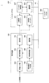
続いて、図4を参照して、本実施形態に係る医療情報処理システム1の機能構成の一例について説明する。図4は、本実施形態に係る医療情報処理システム1の機能構成の一例を示したブロック図である。
<3.2. Functional configuration>
Subsequently, an example of the functional configuration of the medical
図4において、表示装置100及びシャッターグラス300は、図3に示した表示装置100及びシャッターグラス300に対応している。また、図4に示す例では、表示装置100とシャッターグラス300とは、ネットワークN1を介して相互に情報を送受信可能に構成されている。また、医療情報処理システム1は、シャッターグラス300を複数含んでもよい。この場合には、表示装置100は、複数のシャッターグラス300それぞれと、ネットワークN1を介して互いに情報を送受信する。
In FIG. 4, the
(表示装置100)
次いで、表示装置100の構成について説明する。図4に示すように、表示装置100は、表示部101と、画像入力部102と、表示制御部103と、同期信号生成部104と、同期制御部105と、通信部106とを含む。
(Display device 100)
Next, the configuration of the
表示部101は、表示装置100の表示パネルに相当する。表示部101には、後述する表示制御部103による制御に基づき、表示対象となる画像が表示される。
The
画像入力部102は、表示対象となる画像の画像データを入力するための入力インタフェースに相当する。例えば、手術用顕微鏡、内視鏡、術野カメラ、手術カメラ等の撮像装置による撮像結果に基づく画像データが、画像入力部102を介して表示装置100に入力される。なお、以降では、画像入力部102を介して入力される画像データを、「入力画像データ」とも称する。
The
通信部106は、表示装置100が、所定のネットワークN1を介してシャッターグラス300との間で各種情報を送受信するための通信インタフェースである。なお、通信部106の構成は、シャッターグラス300との間の通信の方式に応じて適宜変更されてもよい。例えば、表示装置100とシャッターグラス300とが無線の通信経路を介して通信を行う場合には、通信部106は、ベースバンドプロセッサやRF(Radio Frequency)回路等を含んでもよい。なお、以降の説明では、表示装置100内の構成が他の装置(例えば、シャッターグラス300)との間で情報の送受信を行う場合には、特に説明が無い限りは、当該通信部106を介して情報の送受信が行われるものとする。
The
同期信号生成部104は、入力画像データに応じた左眼用画像及び右眼用画像を時分割で表示するための同期信号(即ち、左眼用画像及び右眼用画像それぞれの表示タイミングに応じた同期信号)を生成する。同期信号生成部104は、生成した同期信号を同期制御部105に出力する。
The synchronization
表示制御部103は、画像入力部102を介して入力された入力画像データに応じた画像を表示部101に表示させることで、当該画像を視聴者に提示する。なお、このとき表示制御部103は、当該画像の提示に係る態様を、後述する同期制御部105からの制御に基づき、3次元画像の提示に係る態様と、2次元画像の提示に係る態様との間で選択的に切り替えてもよい。
The
具体的には、視聴者に対して3次元画像を提示する場合には、表示制御部103は、入力画像データに応じた左眼用画像及び右眼用画像を、同期制御部105から供給される同期信号に基づき時分割で表示部101に表示させる。また、視聴者に対して2次元画像を提示する場合には、表示制御部103は、例えば、入力画像データに応じた左眼用画像及び右眼用画像のうちいずれか一方のみを表示部101に表示させる。
Specifically, when presenting a three-dimensional image to the viewer, the
なお、左眼用画像及び右眼用画像の生成元は特に限定されない。具体的な一例として、所謂ステレオカメラ等のような複数の撮像部を備える撮像装置により、複数の視点からの撮像結果に基づき左眼用画像及び右眼用画像が生成されてもよい。この場合には、入力画像データとして、当該左眼用画像及び当該右眼用画像が表示装置100に入力されることとなる。また、他の一例として、所謂単眼カメラ等の撮像装置による撮像結果に応じた画像データが、入力画像データとして表示装置100に入力されてもよい。この場合には、表示制御部103が、当該入力画像データに基づき左眼用画像及び右眼用画像を生成してもよい。また、このとき表示制御部103は、測距センサ等による画像中に撮像された被写体までの距離の測定結果を利用することで、当該画像に対応する画像データに基づき左眼用画像及び右眼用画像を生成してもよい。
The generation source of the left eye image and the right eye image is not particularly limited. As a specific example, an image for the left eye and an image for the right eye may be generated based on the imaging results from a plurality of viewpoints by an imaging device including a plurality of imaging units such as a so-called stereo camera. In this case, the left eye image and the right eye image are input to the
同期制御部105は、同期信号生成部104から出力される同期信号を表示制御部103に供給するとともに、ネットワークN1を介して当該同期信号をシャッターグラス300に送信する。また、同期制御部105は、当該同期信号に対する応答として、シャッターグラス300から送信される応答信号の受信を試みる。そして、同期制御部105は、当該応答信号の受信状況に応じて、同期信号がシャッターグラス300に正しく受信されたか否かを認識し、当該認識結果に応じて、表示制御部103による画像の提示に係る動作を制御する。
The
具体的には、同期制御部105は、シャッターグラス300が同期信号を正しく受信できていることを認識している限りは、表示制御部103に3次元画像の提示を継続させる。この場合には、表示制御部103は、同期制御部105から供給される同期信号に基づき、左眼用画像及び右眼用画像を時分割で表示する。
Specifically, the
一方で、同期制御部105は、シャッターグラス300が同期信号を正しく受信できていないものと認識した場合には、表示制御部103に対して、2次元画像の提示を指示する。この場合には、表示制御部103は、左眼用画像及び右眼用画像のうちいずれか一方の画像のみを表示部101に表示させる。
On the other hand, when the
また、同期制御部105は、表示制御部103に対して2次元画像の提示を指示した後に、シャッターグラス300が同期信号を正しく受信できるようになったことを認識した場合には、表示制御部103に対して、3次元画像の提示を指示してもよい。
Further, when the
(シャッターグラス300)
次いで、シャッターグラス300の構成について説明する。図4に示すように、シャッターグラス300は、左眼用シャッター301及び右眼用シャッター303と、通信部305と、シャッター制御部307とを含む。なお、左眼用シャッター301及び右眼用シャッター303については、図3を参照して前述したため詳細な説明は省略する。
(Shutter glass 300)
Next, the configuration of the
通信部305は、シャッターグラス300が、所定のネットワークN1を介して表示装置100との間で各種情報を送受信するための通信インタフェースである。なお、通信部305の構成は、前述した通信部106と同様に、表示装置100との間の通信の方式に応じて適宜変更されてよい。なお、以降の説明では、シャッターグラス300内の構成が他の装置(例えば、表示装置100)との間で情報の送受信を行う場合には、特に説明が無い限りは、当該通信部305を介して情報の送受信が行われるものとする。
The
シャッター制御部307は、ネットワークN1を介して表示装置100から送信される同期信号に基づき、当該同期信号が示すタイミングに同期するように左眼用シャッター301及び右眼用シャッター303それぞれの開閉を制御する。
The
また、シャッター制御部307は、表示装置100から送信される同期信号の受信状況に応じて、当該同期信号に対する応答として応答信号を当該表示装置100にネットワークN1を介して送信する。例えば、シャッター制御部307は、当該同期信号を正しく受信できたか否かを、応答信号により表示装置100に通知する。
Further, the
なお、上述した医療情報処理システム1の構成はあくまで一例であり、必ずしも図4に示す例には限定されない。具体的な一例として、表示装置100の各構成のうち一部の構成が当該表示装置100の外部に設けられていてもよい。より具体的な一例として、表示装置100の各構成のうち、同期制御や表示制御に係る部分(例えば、同期信号生成部104、同期制御部105、通信部106、及び表示制御部103等)が、表示装置100の外部に外付けされる他の装置として構成されていてもよい。なお、当該表示装置100に対して外付けされる当該他の装置が、「医療画像表示装置」の一例に相当する。
The configuration of the medical
以上、図4を参照して、本実施形態に係る医療情報処理システム1の機能構成の一例について説明した。
As described above, an example of the functional configuration of the medical
<3.3.処理>
続いて、図5〜図7を参照して、本実施形態に係る医療情報処理システム1の一連の処理の流れの一例について、特に、表示装置100の動作に着目して説明する。例えば、図5は、本実施形態に係る医療情報処理システム1の一連の処理の流れの一例を示したフローチャートである。
<3.3. Processing>
Subsequently, with reference to FIGS. 5 to 7, an example of a series of processing flows of the medical
図5に示すように、まず表示装置100(表示制御部103)は、画像入力部102を介して入力された入力画像データに基づき、視聴者に対して3次元画像を提示する。具体的には、表示装置100は、入力画像データに応じた左眼用画像及び右眼用画像を、生成した同期信号に基づき時分割で表示パネル(表示部101)に表示させる(S111)。
As shown in FIG. 5, first, the display device 100 (display control unit 103) presents a three-dimensional image to the viewer based on the input image data input via the
また、表示装置100(同期制御部105)は、生成した同期信号を、所定のネットワークN1を介してシャッターグラス300に送信する(S113)。次いで、同期制御部105は、当該同期信号に対する応答として、シャッターグラス300から送信される応答信号の受信を試み、当該応答信号の受信状況に応じて、以降における入力画像データに応じた画像の表示に係る動作を選択的に切り替える。
Further, the display device 100 (synchronization control unit 105) transmits the generated synchronization signal to the
例えば、表示装置100(同期制御部105)は、同期信号に対する応答として、シャッターグラス300から応答信号を正しく受信できた場合には(S115、YES)、シャッターグラス300が同期信号を正しく受信できているものと認識する。この場合には、表示装置100(表示制御部103)は、一連の処理の終了が指示されない限りは(S117、NO)、3次元画像の提示を継続する(S111)。
For example, when the display device 100 (synchronization control unit 105) can correctly receive the response signal from the
ここで、図6を参照して、視聴者に対して3次元画像を提示する場合における、表示装置100及びシャッターグラス300それぞれの動作のタイミングの一例について説明する。図6は、本実施形態に係る医療情報処理システム1による画像の提示に係るタイミングチャートの一例であり、視聴者に対して3次元画像を提示する場合における、表示装置100及びシャッターグラス300それぞれの動作のタイミングを模式的に示している。具体的には、図6に示すタイミングチャートでは、表示装置100が左眼用画像及び右眼用画像を表示するタイミングと、シャッターグラス300が左眼用シャッター及び右眼用シャッターのそれぞれを開閉するタイミングとを示している。なお、図6に示す例において、左眼用画像及び右眼用画像のそれぞれは、ON状態において表示パネル(表示部101)に表示され、OFF状態においては非表示となる。また、左眼用シャッター及び右眼用シャッターのそれぞれは、ON状態において開かれるように制御され、OFF状態において閉じられるように制御される。
Here, with reference to FIG. 6, an example of the operation timing of each of the
具体的には、図6に示す例では、例えば、左眼用画像が表示されるタイミングにおいては、当該タイミングに同期して、左眼用シャッターが開かれるように制御され、右眼用シャッターが閉じられるように制御される。即ち、同タイミングにおいては、視聴者の左右の眼のうち、左眼にのみ左眼用画像が観測されることとなる。また、右眼用画像が表示されるタイミングにおいては、当該タイミングに同期して、左眼用シャッターが閉じられるように制御され、右眼用シャッターが開かれるように制御される。即ち、同タイミングにおいては、視聴者の左右の眼のうち、右眼にのみ右眼用画像が観測されることとなる。以上のような制御により、視聴者は、表示対象となる画像を3次元画像として観測することとなる。 Specifically, in the example shown in FIG. 6, for example, at the timing when the image for the left eye is displayed, the shutter for the left eye is controlled to be opened in synchronization with the timing, and the shutter for the right eye is released. It is controlled to be closed. That is, at the same timing, the image for the left eye is observed only in the left eye among the left and right eyes of the viewer. Further, at the timing when the image for the right eye is displayed, the shutter for the left eye is controlled to be closed and the shutter for the right eye is controlled to be opened in synchronization with the timing. That is, at the same timing, the image for the right eye is observed only in the right eye among the left and right eyes of the viewer. With the above control, the viewer observes the image to be displayed as a three-dimensional image.
一方で、図5に示すように、表示装置100(同期制御部105)は、同期信号に対する応答として、シャッターグラス300から応答信号を正しく受信できなかった場合には(S115、NO)、シャッターグラス300が同期信号を正しく受信できていないものと認識する。この場合には、表示装置100(表示制御部103)は、画像入力部102を介して入力された入力画像データに基づき、視聴者に対して2次元画像を提示する。具体的には、表示装置100は、入力画像データに応じた左眼用画像及び右眼用画像のうちいずれか一方の画像のみを表示パネル(表示部101)に表示させる(S121)。
On the other hand, as shown in FIG. 5, when the display device 100 (synchronization control unit 105) cannot correctly receive the response signal from the
また、表示装置100(同期制御部105)は、生成した同期信号を、所定のネットワークN1を介してシャッターグラス300に送信し(S123)、当該同期信号に対する応答として、シャッターグラス300から送信される応答信号の受信を試みる。
Further, the display device 100 (synchronization control unit 105) transmits the generated synchronization signal to the
表示装置100(表示制御部103)は、シャッターグラス300から応答信号を正しく受信できない状況が継続している場合には(S125、NO)、一連の処理の終了が指示されない限りは(S127、NO)、2次元画像の提示を継続する(S121)。 The display device 100 (display control unit 103) continues to be unable to correctly receive the response signal from the shutter glass 300 (S125, NO), unless instructed to end a series of processes (S127, NO). ), The presentation of the two-dimensional image is continued (S121).
ここで、図7を参照して、視聴者に対して2次元画像を提示する場合における、表示装置100及びシャッターグラス300それぞれの動作のタイミングの一例について説明する。図7は、本実施形態に係る医療情報処理システム1による画像の提示に係るタイミングチャートの一例であり、視聴者に対して2次元画像を提示する場合における、表示装置100及びシャッターグラス300それぞれの動作のタイミングを模式的に示している。具体的には、図7に示すタイミングチャートでは、図6に示す例と同様に、表示装置100が左眼用画像及び右眼用画像を表示するタイミングと、シャッターグラス300が左眼用シャッター及び右眼用シャッターのそれぞれを開閉するタイミングとを示している。なお、図7に示す例における、左眼用画像及び右眼用画像のON状態及びOFF状態と、左眼用シャッター及び右眼用シャッターのON状態及びOFF状態とは、図6に示す例と同様である。
Here, with reference to FIG. 7, an example of the operation timing of each of the
例えば、図7に示す例では、表示装置100は、参照符号t11で示されたタイミングで、3次元画像の提示から、2次元画像の提示に切り替えている。即ち、表示装置100は、タイミングt11以降については、左眼用画像及び右眼用画像のうち左眼用画像のみが表示パネル(表示部101)に表示されるように制御している。この場合には、左眼用シャッター及び右眼用シャッターのそれぞれが個別に開かれるいずれのタイミングにおいても、表示パネルには左眼用画像が表示される。即ち、視聴者の左右の眼の双方に左眼用画像が観測されることとなる。そのため、以上のような制御により、視聴者は、表示対象となる画像を2次元画像として観測することとなる。
For example, in the example shown in FIG. 7, the
一方で、図5に示すように、表示装置100(同期制御部105)は、2次元画像の提示に切り替えた後に、シャッターグラス300から応答信号を正しく受信できた場合には(S125、YES)、シャッターグラス300が同期信号R11を正しく受信できるようになったものと認識する。この場合には、表示装置100(表示制御部103)は、以降における入力画像データに応じた画像の表示に係る動作を、2次元画像の提示に係る動作から、3次元画像の提示に係る動作に切り替える(S111)。
On the other hand, as shown in FIG. 5, when the display device 100 (synchronous control unit 105) can correctly receive the response signal from the
そして、表示装置100は、電源の切断や機能の停止等により一連の処理の終了が指示されると(S117、YES、または、S127、YES)、上述した入力画像データに応じた画像の表示に係る一連の処理を終了する。
Then, when the
以上、図5〜図7を参照して、本実施形態に係る医療情報処理システム1の一連の処理の流れの一例について、特に、表示装置100の動作に着目して説明した。
As described above, with reference to FIGS. 5 to 7, an example of a series of processing flows of the medical
<3.4.変形例>
続いて、本実施形態に係る医療情報処理システムの変形例について説明する。
<3.4. Modification example>
Subsequently, a modified example of the medical information processing system according to the present embodiment will be described.
(変形例1:複数のシャッターグラスが動作する場合の制御例)
まず、変形例1として、表示装置100が、複数のシャッターグラス300に対して同期信号を送信する場合における、当該複数のシャッターグラス300それぞれからの応答信号の受信状況に応じた、画像の表示に係る動作の一例について説明する。
(Modification example 1: Control example when multiple shutter glasses operate)
First, as a
表示装置100が、同期信号を送信した複数のシャッターグラス300それぞれから送信される応答信号の受信を試みるような状況下では、一部のシャッターグラス300から当該応答信号が正しく受信できない場合が想定され得る。例えば、図8は、変形例1に係る医療情報処理システムの動作の一態様について説明するための説明図である。具体的には、図8は、表示装置100がシャッターグラス300a〜300cのそれぞれに対して同期信号を送信し、シャッターグラス300b及び300cからのみ応答信号を受信した場合の一例を示している。即ち、図8に示す例では、何らかの要因により、表示装置100は、シャッターグラス300aからの応答信号を正しく受信できておらず、当該シャッターグラス300aが同期信号を正しく受信できていないものと認識する。
In a situation where the
このような場合には、例えば、表示装置100は、応答信号を正しく受信できていないシャッターグラス300aを使用する視聴者(換言すると、シャッターグラス300aに関連付けられたユーザ)に応じて、入力画像データに応じた画像の表示に係る動作を制御してもよい。換言すると、表示装置100は、複数のシャッターグラス300a〜300cのうち、所定の視聴者が使用するシャッターグラス300(例えば、シャッターグラス300a)からの応答信号の受信状況に応じて、入力画像データに応じた画像の表示に係る動作を制御してもよい。
In such a case, for example, the
具体的な一例として、前述した医療用観察蔵置による患部の撮像結果を確認しながら各種手技を行う術者がシャッターグラス300aを使用し、助手、麻酔科医、または看護師等がシャッターグラス300bまたは300cを使用しているものとする。このような状況下で、例えば、術者、助手、麻酔科医、及び看護師のうち、術者が上記所定の視聴者として設定されたものとする。この場合には、表示装置100は、上記術者が使用するシャッターグラス300aから応答信号が正しく受信できなかった場合に、入力画像データに応じた画像の提示態様を、3次元画像の提示に係る態様から、2次元画像の提示に係る態様に切り替えてもよい。
As a specific example, an operator who performs various procedures while checking the imaging result of the affected area by the above-mentioned medical observation storage uses the
このような制御により、表示装置100とシャッターグラス300aとの間の同期が困難となり、当該シャッターグラス300aを使用する術者が、患部の3次元画像を観測することが困難となった場合においても、当該術者に対して、当該患部の画像が2次元画像として提示されることとなる。そのため、当該術者は、当該患部の画像を立体感のある3次元画像として観測することが困難とはなるものの、当該患部の画像の観測を継続することが可能となる。なお、所定の視聴者が使用するシャッターグラス300(即ち、所定のシャッターグラス300)については、例えば、監視対象としてあらかじめ設定しておけばよい。また、表示装置100は、例えば、応答信号に関連付けられた情報(例えば、識別情報等)に基づき、当該応答信号の送信元となるシャッターグラス300を認識すればよい。これにより、表示装置100は、一部のシャッターグラス300から応答信号が正しく受信できていない場合においても、当該シャッターグラス300を認識することが可能となる。
Such control makes it difficult to synchronize the
これに対して、図9は、変形例1に係る医療情報処理システムの動作の他の一態様について説明するための説明図である。具体的には、図9は、表示装置100がシャッターグラス300a〜300cのそれぞれに対して同期信号を送信し、シャッターグラス300a及び300bからのみ応答信号を受信した場合の一例を示している。即ち、図9に示す例では、何らかの要因により、表示装置100は、シャッターグラス300cからの応答信号を正しく受信できておらず、当該シャッターグラス300cが同期信号を正しく受信できていないものと認識する。
On the other hand, FIG. 9 is an explanatory diagram for explaining another aspect of the operation of the medical information processing system according to the first modification. Specifically, FIG. 9 shows an example in which the
ここで、図8を参照して上述した例と同様に、所定の手技を行う術者が上記所定の視聴者として設定され、当該術者がシャッターグラス300aを使用しており、シャッターグラス300b及び300cについては、当該術者以外の他の視聴者が使用しているものとする。即ち、図9に示す例は、表示装置100とシャッターグラス300cとの間の同期が困難となり、当該シャッターグラス300cを使用する術者以外の他の視聴者が、患部の3次元画像を観測することが困難となった場合の一例を示している。また、図9に示す例では、表示装置100とシャッターグラス300aとの間の同期は正常に行われており、シャッターグラス300aを使用する術者は、患部の3次元画像を正しく観測することが可能となっている。このような場合には、表示装置100は、入力画像データに応じた3次元画像の提示を継続してもよい。
Here, as in the above-described example with reference to FIG. 8, an operator performing a predetermined procedure is set as the predetermined viewer, and the operator is using the
なお、上述した、複数のシャッターグラス300それぞれからの応答信号の受信状況に応じて、画像データに応じた画像の提示態様を切り替える制御はあくまで一例であり、必ずしも上述した例には限定されない。具体的な一例として、表示装置100は、複数のシャッターグラス300のうち少なくともいずれかが同期信号を正しく受信できていないものと認識した場合には、入力画像データに応じた画像の提示態様を、3次元画像の提示に係る態様から、2次元画像の提示に係る態様に切り替えてもよい。この場合には、表示装置100は、図8及び図9に示すいずれの場合においても、入力画像データに応じた画像の提示態様を、2次元画像の提示に係る態様に切り替えることとなる。
It should be noted that the control of switching the presentation mode of the image according to the image data according to the reception status of the response signals from each of the plurality of
以上、変形例1として、図8及び図9を参照して、表示装置100が、複数のシャッターグラス300に対して同期信号を送信する場合における、当該複数のシャッターグラス300それぞれからの応答信号の受信状況に応じた、画像の表示に係る動作の一例について説明した。
As described above, as a
(変形例2:シャッターグラス側での切り替え)
続いて、変形例2として、シャッターグラス300側で、画像の提示態様を、3次元画像の提示に係る態様と、2次元画像の提示に係る態様との間で選択的に切り替える場合の一例について説明する。
(Modification example 2: Switching on the shutter glass side)
Subsequently, as a modification 2, an example in which the image presentation mode is selectively switched between the mode related to the presentation of the three-dimensional image and the mode related to the presentation of the two-dimensional image on the
本変形例では、表示装置100が左眼用画像と右眼用画像を時分割で表示している場合においても、シャッターグラス300側が、左眼用シャッター及び右眼用シャッターの開閉タイミングを制御することで、画像の提示態様を切り替える。具体的には、シャッターグラス300は、表示装置100が左眼用画像及び右眼用画像のうちのいずれかの画像を表示するタイミングに同期して、左眼用シャッターと右眼用シャッターとが同時に開閉するように制御することで、視聴者に対して2次元画像を提示する。
In this modification, the
例えば、図10は、変形例2に係る医療情報処理システムの概要について説明するための説明図であり、当該医療情報処理システムによる画像の提示に係るタイミングチャートの一例を示している。具体的には、図10に示すタイミングチャートでは、表示装置100が左眼用画像及び右眼用画像を表示するタイミングと、シャッターグラス300が左眼用シャッター及び右眼用シャッターのそれぞれを開閉するタイミングとを示している。なお、図10に示す例における、左眼用画像及び右眼用画像のON状態及びOFF状態と、左眼用シャッター及び右眼用シャッターのON状態及びOFF状態とは、図6を参照して説明した例と同様である。
For example, FIG. 10 is an explanatory diagram for explaining the outline of the medical information processing system according to the modified example 2, and shows an example of a timing chart related to the presentation of an image by the medical information processing system. Specifically, in the timing chart shown in FIG. 10, the timing at which the
例えば、図10に示す例では、シャッターグラス300は、参照符号t13で示されたタイミングで、3次元画像の提示から、2次元画像の提示に切り替えている。具体的には、タイミングt13以前においては、シャッターグラス300は、図6を参照して説明した例と同様に、左眼用シャッター及び右眼用シャッターの開閉を制御している。即ち、タイミングt13以前においては、視聴者は、表示対象となる画像を3次元画像として観測することとなる。
For example, in the example shown in FIG. 10, the
これに対して、タイミングt13以降においては、シャッターグラス300は、左眼用画像が表示されるタイミングに同期して、左眼用シャッター及び右眼用シャッターの双方が開かれるように制御する。即ち、同タイミングにおいては、視聴者の左右の眼の双方に左眼用画像が観測されることとなる。また、シャッターグラス300は、右眼用画像が表示されるタイミングに同期して、左眼用シャッター及び右眼用シャッターの双方が閉じられるように制御する。即ち、同タイミングにおいては、視聴者の左右の眼の双方には、画像(即ち、右眼用画像)が観測されないこととなる。以上のような制御により、タイミングt13以降においては、視聴者は、表示対象となる画像を2次元画像として観測することとなる。
On the other hand, after the timing t13, the
なお、シャッターグラス300が所定の条件に応じて上記切り替えを行うことが可能であれば、当該切り替えの契機は特に限定されない。具体的な一例として、シャッターグラス300に対してスイッチ等の入力部を設け、当該シャッターグラス300は、当該入力部への操作を受けて、画像の提示態様を、3次元画像の提示に係る態様と、2次元画像の提示に係る態様との間で切り替えてもよい。
If the
以上、変形例2として、図10を参照して、シャッターグラス300側で、画像の提示態様を、3次元画像の提示に係る態様と、2次元画像の提示に係る態様との間で選択的に切り替える場合の一例について説明した。
As described above, as a modification 2, referring to FIG. 10, the image presentation mode is selectively selected between the mode relating to the presentation of the three-dimensional image and the mode relating to the presentation of the two-dimensional image on the
<<4.適用例>>
続いて、本開示の一実施形態に係る医療情報処理システムの適用例について説明する。上記では、本開示の一実施形態に係る医療情報処理システムにおける医療用立体観察装置として、手術用ビデオ顕微鏡装置に適用した場合の一例について説明した。一方で、本実施形態に医療情報処理システムにおいて、医療用立体観察装置として適用される装置は、必ずしも手術用ビデオ顕微鏡装置のみには限定されない。そこで、本実施形態に係る医療情報処理システムにおいて、医療用立体観察装置として適用され得る装置の一例について以下に説明する。
<< 4. Application example >>
Subsequently, an application example of the medical information processing system according to the embodiment of the present disclosure will be described. In the above, an example in the case of being applied to a surgical video microscope device as a medical stereoscopic observation device in the medical information processing system according to the embodiment of the present disclosure has been described. On the other hand, in the medical information processing system of the present embodiment, the device applied as the medical stereoscopic observation device is not necessarily limited to the surgical video microscope device. Therefore, in the medical information processing system according to the present embodiment, an example of an apparatus that can be applied as a medical stereoscopic observation apparatus will be described below.
<4.1.第1の適用例:硬性内視鏡装置>
まず、図11及び図12を参照して、本実施形態の第1の適用例について説明する。本適用例では、本実施形態に係る医療情報処理システムにおける医療用立体観察装置として、所謂硬性内視鏡装置を適用した場合の一例について説明する。例えば、図11は、本実施形態に係る医療情報処理システムに適用される医療用立体観察装置の一例について説明するための説明図であり、硬性内視鏡装置の概略的な構成の一例について示している。内視鏡装置700は、医療分野において用いられ、人等の観察対象物の内部(生体内)の被写体を観察する装置である。この内視鏡装置700は、図11に示すように、内視鏡720と、撮像装置730(医療用撮像装置)と、表示装置740と、制御装置750(画像処理装置)と、光源装置760とを備え、撮像装置730と制御装置750とで、医療用画像取得システムを構成している。なお、本適用例では、内視鏡720と撮像装置730とで、硬性鏡を用いた内視鏡装置を構成している。
<4.1. First application example: rigid endoscope device>
First, a first application example of the present embodiment will be described with reference to FIGS. 11 and 12. In this application example, an example in which a so-called rigid endoscope device is applied as a medical stereoscopic observation device in the medical information processing system according to the present embodiment will be described. For example, FIG. 11 is an explanatory diagram for explaining an example of a medical stereoscopic observation device applied to the medical information processing system according to the present embodiment, and shows an example of a schematic configuration of a rigid endoscope device. ing. The
光源装置760は、ライトガイド770の一端が内視鏡720に接続され、当該ライトガイド770の一端に生体内を照明するための白色の照明光を供給する。ライトガイド770は、一端が光源装置760に着脱自在に接続されるとともに、他端が内視鏡720に着脱自在に接続される。そして、ライトガイド770は、光源装置760から供給された光を一端から他端に伝達し、内視鏡720に供給する。
In the
撮像装置730は、内視鏡720からの被写体像を撮像して当該撮像結果を出力する。この撮像装置730は、図11に示すように、信号伝送部である伝送ケーブル780と、カメラヘッド790とを備える。本実施の形態1では、伝送ケーブル780とカメラヘッド790とにより医療用撮像装置が構成される。
The
内視鏡720は、硬質で細長形状を有し、生体内に挿入される。この内視鏡720の内部には、1または複数のレンズを用いて構成され、被写体像を集光する光学系が設けられている。内視鏡720は、ライトガイド770を介して供給された光を先端から出射し、生体内に照射する。そして、生体内に照射された光(被写体像)は、内視鏡720内の光学系(レンズユニット791)により集光される。
The
カメラヘッド790は、内視鏡720の基端に着脱自在に接続される。そして、カメラヘッド790は、制御装置750による制御の下、内視鏡720にて集光された被写体像を撮像し、当該撮像による撮像信号を出力する。
The
伝送ケーブル780は、一端がコネクタを介して制御装置750に着脱自在に接続されるとともに、他端がコネクタを介してカメラヘッド790に着脱自在に接続される。具体的に、伝送ケーブル780は、最外層である外被の内側に複数の電気配線(図示略)が配設されたケーブルである。当該複数の電気配線は、カメラヘッド790から出力される撮像信号、制御装置750から出力される制御信号、同期信号、クロック、及び電力をカメラヘッド790にそれぞれ伝送するための電気配線である。
One end of the
表示装置740は、制御装置750による制御のもと、制御装置750により生成された画像(即ち、医療画像)を表示する。表示装置740は、観察時の没入感を得やすくするために、表示部が55インチ以上を有するものが好ましいが、これに限らない。
The
制御装置750は、カメラヘッド790から伝送ケーブル780を経由して入力された撮像信号を処理し、表示装置740へ画像信号を出力するとともに、カメラヘッド790及び表示装置740の動作を統括的に制御する。なお、制御装置750の詳細な構成については、後述する。
The
次に、撮像装置730及び制御装置750の構成について説明する。図12は、本実施形態に係る医療情報処理システムに適用される医療用立体観察装置の一例について説明するための説明図であり、撮像装置730及び制御装置750の構成を示すブロック図である。なお、図12では、カメラヘッド790及び伝送ケーブル780同士を着脱可能とするコネクタの図示を省略している。
Next, the configurations of the
以下、制御装置750の構成、及びカメラヘッド790の構成の順に説明する。なお、以下では、制御装置750の構成として、本開示に係る要部を主に説明する。制御装置750は、図12に示すように、信号処理部751と、画像生成部752と、通信モジュール753と、入力部754と、制御部755と、メモリ756とを備える。なお、制御装置750には、制御装置750及びカメラヘッド790を駆動するための電源電圧を生成し、制御装置750の各部にそれぞれ供給するとともに、伝送ケーブル780を介してカメラヘッド790に供給する電源部(図示略)などが設けられていてもよい。
Hereinafter, the configuration of the
信号処理部751は、カメラヘッド790が出力した撮像信号に対してノイズ除去や、必要に応じてA/D変換等の信号処理を行うことによって、デジタル化された撮像信号(パルス信号)を画像生成部752に出力する。
The
また、信号処理部751は、撮像装置730及び制御装置750の同期信号、及びクロックを生成する。撮像装置730への同期信号(例えば、カメラヘッド790の撮像タイミングを指示する同期信号等)やクロック(例えばシリアル通信用のクロック)は、図示しないラインで撮像装置730に送られ、この同期信号やクロックを基に、撮像装置730は駆動する。
Further, the
画像生成部752は、信号処理部751から入力される撮像信号をもとに、表示装置740が表示する表示用の画像信号を生成する。画像生成部752は、撮像信号に対して、所定の信号処理を実行して被写体画像を含む表示用の画像信号を生成する。ここで、画像処理としては、補間処理や、色補正処理、色強調処理、及び輪郭強調処理等の各種画像処理等が挙げられる。画像生成部752は、生成した画像信号を表示装置740に出力する。
The
通信モジュール753は、制御部755から送信された後述する制御信号を含む制御装置750からの信号を撮像装置730に出力する。また、撮像装置730からの信号を制御装置750に出力する。つまり通信モジュール753は、撮像装置730へ出力する制御装置750の各部からの信号を、例えばパラレルシリアル変換等によりまとめ出力し、また撮像装置730から入力される信号を、例えばシリアルパラレル変換等により振り分け制御装置750の各部に出力する、中継デバイスである。
The
入力部754は、キーボード、マウス、タッチパネル等のユーザインタフェースを用いて実現され、各種情報の入力を受け付ける。
The
制御部755は、制御装置750及びカメラヘッド790を含む各構成部の駆動制御、および各構成部に対する情報の入出力制御などを行う。制御部755は、メモリ756に記録されている通信情報データ(例えば、通信用フォーマット情報など)を参照して制御信号を生成し、該生成した制御信号を、通信モジュール753を介して撮像装置730へ送信する。また、制御部755は、伝送ケーブル780を介して、カメラヘッド790に対して制御信号を出力する。
The
メモリ756は、フラッシュメモリやDRAM(Dynamic Random Access Memory)等の半導体メモリを用いて実現され、通信情報データ(例えば、通信用フォーマット情報など)が記録されている。なお、メモリ756は、制御部755が実行する各種プログラム等が記録されていてもよい。
The
なお、信号処理部751が、入力されたフレームの撮像信号を基に、各フレームの所定のAF用評価値を出力するAF処理部、及び、AF処理部からの各フレームのAF用評価値から、最も合焦位置として適したフレームまたはフォーカスレンズ位置等を選択するようなAF演算処理を行うAF演算部を有していてもよい。 From the AF processing unit that outputs the predetermined AF evaluation value of each frame based on the input frame imaging signal, and the AF evaluation value of each frame from the AF processing unit. It may have an AF calculation unit that performs AF calculation processing such as selecting the most suitable frame or focus lens position as the focusing position.
なお、上述した信号処理部751、画像生成部752、通信モジュール753および制御部755は、プログラムが記録された内部メモリ(図示略)を有するCPU(Central Processing Unit)等の汎用プロセッサやASIC(Application Specific Integrated Circuit)等の特定の機能を実行する各種演算回路等の専用プロセッサを用いて実現される。また、プログラマブル集積回路の一種であるFPGA(Field Programmable Gate Array:図示略)を用いて構成するようにしてもよい。なおFPGAにより構成される場合は、コンフィグレーションデータを記憶するメモリを設け、メモリから読み出したコンフィグレーションデータにより、プログラマブル集積回路であるFPGAをコンフィグレーションしてもよい。
The
次に、カメラヘッド790の構成として、本発明の要部を主に説明する。カメラヘッド790は、図12に示すように、レンズユニット791と、撮像部792と、駆動部793と、通信モジュール794と、カメラヘッド制御部795とを備える。
Next, a main part of the present invention will be mainly described as a configuration of the
レンズユニット791は、1または複数のレンズを用いて構成され、内視鏡720にて集光された被写体像を、撮像部792を構成する撮像素子の撮像面に結像する。当該1または複数のレンズは、光軸に沿って移動可能に構成されている。そして、レンズユニット791には、当該1または複数のレンズを移動させて、画角を変化させる光学ズーム機構(図示略)や焦点を変化させるフォーカス機構が設けられている。なお、レンズユニット791は、光学ズーム機構およびフォーカス機構のほか、絞り機構や、光軸上に挿脱自在な光学フィルタ(例えば赤外光をカットするフィルタ)が設けられていてもよい。
The
撮像部792は、カメラヘッド制御部795による制御の下、被写体を撮像する。この撮像部792は、レンズユニット791が結像した被写体像を受光して電気信号に変換するCCD(Charge Coupled Device)またはCMOS(Complementary Metal Oxide Semiconductor)等の二つの撮像素子と、観察光を分光して、分光した光を二つの撮像素子にそれぞれ入射させるプリズムと、を用いて構成されている。CCDの場合は、例えば、当該撮像素子からの電気信号(アナログ信号)に対して信号処理(A/D変換等)を行って撮像信号を出力する信号処理部(図示略)がセンサチップなどに実装される。CMOSの場合は、例えば、光から電気信号に変換された電気信号(アナログ)に対して信号処理(A/D変換等)を行って撮像信号を出力する信号処理部が撮像素子に含まれる。撮像部792の構成については、後述する。
The
駆動部793は、カメラヘッド制御部795による制御の下、光学ズーム機構やフォーカス機構を動作させ、レンズユニット791の画角や焦点位置を変化させるドライバを有する。
The
通信モジュール794は、制御装置750から送信された信号をカメラヘッド制御部795等のカメラヘッド790内の各部に出力する。また、通信モジュール794は、カメラヘッド790の現在の状態に関する情報などを予め決められた伝送方式に応じた信号形式に変換し、伝送ケーブル780を介して当該変換した信号を制御装置750に出力する。つまり通信モジュール794は、制御装置750や伝送ケーブル780から入力される信号を、例えばシリアルパラレル変換等により振り分けカメラヘッド790の各部に出力し、また制御装置750や伝送ケーブル780へ出力するカメラヘッド790の各部からの信号を、例えばパラレルシリアル変換等によりまとめ出力する、中継デバイスである。
The
カメラヘッド制御部795は、伝送ケーブル780を介して入力した駆動信号や、カメラヘッド790の外面に露出して設けられたスイッチ等の操作部へのユーザ操作により操作部から出力される指示信号等に応じて、カメラヘッド790全体の動作を制御する。また、カメラヘッド制御部795は、伝送ケーブル780を介して、カメラヘッド790の現在の状態に関する情報を制御装置750に出力する。
The camera
なお、上述した駆動部793、通信モジュール794およびカメラヘッド制御部795は、プログラムが記録された内部メモリ(図示略)を有するCPU(Central Processing Unit)等の汎用プロセッサやASIC(Application Specific Integrated Circuit)等の特定の機能を実行する各種演算回路等の専用プロセッサを用いて実現される。また、プログラマブル集積回路の一種であるFPGAを用いて構成するようにしてもよい。なお、FPGAにより構成される場合は、コンフィグレーションデータを記憶するメモリを設け、メモリから読み出したコンフィグレーションデータにより、プログラマブル集積回路であるFPGAをコンフィグレーションしてもよい。
The above-mentioned
なお、カメラヘッド790や伝送ケーブル780に、通信モジュール794や撮像部792により生成された撮像信号に対して信号処理を施す信号処理部を構成するようにしてもよい。また、カメラヘッド790内部に設けられた発振器(図示略)で生成された基準クロックに基づいて、撮像部792を駆動するための撮像用クロック、及び駆動部793を駆動するための駆動用クロックを生成し、撮像部792及び駆動部793にそれぞれ出力するようにしてもよいし、伝送ケーブル780を介して制御装置750から入力した同期信号に基づいて、撮像部792、駆動部793、及びカメラヘッド制御部795における各種処理のタイミング信号を生成し、撮像部792、駆動部793、及びカメラヘッド制御部795にそれぞれ出力するようにしてもよい。また、カメラヘッド制御部795をカメラヘッド790ではなく伝送ケーブル780や制御装置750に設けてもよい。
The
なお、表示装置740が、図3を参照して前述した表示装置100に相当し得る。
The
以上、図11及び図12を参照して、本実施形態に係る医療情報処理システムにおける医療用立体観察装置として、所謂硬性内視鏡装置を適用した場合の一例について説明した。 As described above, with reference to FIGS. 11 and 12, an example in which a so-called rigid endoscope device is applied as a medical stereoscopic observation device in the medical information processing system according to the present embodiment has been described.
<4.2.第2の適用例:軟性内視鏡装置>
続いて、図13を参照して、本実施形態の第2の適用例について説明する。本適用例では、本実施形態に係る医療情報処理システムにおける医療用立体観察装置として、所謂軟性内視鏡装置を適用した場合の一例について説明する。図13は、本実施形態に係る医療情報処理システムに適用される医療用立体観察装置の他の一例について説明するための説明図であり、軟性内視鏡装置の概略的な構成の一例について示している。
<4.2. Second application example: Flexible endoscope device>
Subsequently, a second application example of the present embodiment will be described with reference to FIG. In this application example, an example in which a so-called flexible endoscope device is applied as a medical stereoscopic observation device in the medical information processing system according to the present embodiment will be described. FIG. 13 is an explanatory diagram for explaining another example of the medical stereoscopic observation device applied to the medical information processing system according to the present embodiment, and shows an example of a schematic configuration of the flexible endoscope device. ing.
上述した第1の適用例では、内視鏡720として、硬性鏡を用いた内視鏡装置700を説明したが、これに限られず、内視鏡720に軟性鏡を用いた内視鏡装置としても構わない。本実施形態の第2の適用例では、軟性の内視鏡の挿入部の先端に撮像部を設ける場合の例を説明する。
In the first application example described above, the
内視鏡装置800は、被検体内に挿入部811を挿入することによって観察部位の体内画像を撮像して電気信号を生成する内視鏡810と、内視鏡810の先端から出射する照明光を発生する光源装置820と、内視鏡810が取得した電気信号に所定の画像処理を施すとともに、内視鏡装置800全体の動作を統括的に制御する制御装置830と、プロセッサ部が画像処理を施した体内画像を表示する表示装置840と、を備える。内視鏡装置800は、患者等の被検体内に、挿入部811を挿入して被検体内の体内画像を取得する。
The
内視鏡810は、可撓性を有する細長形状をなす挿入部811と、挿入部811の基端側に接続され、各種の操作信号の入力を受け付ける操作部812と、操作部812から挿入部811が延びる方向と異なる方向に延び、光源装置820および制御装置830に接続する各種ケーブルを内蔵するユニバーサルコード813と、を備える。
The
挿入部811は、本適用例にかかる撮像部を内蔵した先端部814と、複数の湾曲駒によって構成された湾曲自在な湾曲部815と、湾曲部815の基端側に接続され、可撓性を有する長尺状の可撓管部816と、を有する。
The
なお、表示装置840が、例えば、図3を参照して前述した表示装置100に相当し得る。
The
以上、図13を参照して、本実施形態に係る医療情報処理システムにおける医療用立体観察装置として、所謂軟性内視鏡装置を適用した場合の一例について説明した。 As described above, with reference to FIG. 13, an example in which a so-called flexible endoscope device is applied as a medical stereoscopic observation device in the medical information processing system according to the present embodiment has been described.
なお、上述した第1及び第2の適用例は、あくまで本実施形態に係る医療用立体観察装置の一適用例に過ぎず、当該医療用立体観察装置の適用先を限定するものではないことは言うまでもない。 The above-mentioned first and second application examples are merely one application example of the medical stereoscopic observation device according to the present embodiment, and do not limit the application destination of the medical stereoscopic observation device. Needless to say.
<<5.ハードウェア構成>>
次に、図14を参照しながら、本実施形態に係る医療情報処理システムを構成する情報処理装置900のハードウェア構成について、詳細に説明する。図14は、本開示の一実施形態に係る医療情報処理システムを構成する情報処理装置900のハードウェア構成の一構成例を示す機能ブロック図である。
<< 5. Hardware configuration >>
Next, with reference to FIG. 14, the hardware configuration of the
本実施形態に係る医療用立体観察システムを構成する情報処理装置900は、主に、CPU901と、ROM903と、RAM905と、を備える。また、情報処理装置900は、更に、ホストバス907と、ブリッジ909と、外部バス911と、インタフェース913と、入力装置915と、出力装置917と、ストレージ装置919と、ドライブ921と、接続ポート923と、通信装置925とを備える。
The
CPU901は、演算処理装置及び制御装置として機能し、ROM903、RAM905、ストレージ装置919又はリムーバブル記録媒体927に記録された各種プログラムに従って、情報処理装置900内の動作全般又はその一部を制御する。ROM903は、CPU901が使用するプログラムや演算パラメータ等を記憶する。RAM905は、CPU901が使用するプログラムや、プログラムの実行において適宜変化するパラメータ等を一次記憶する。これらはCPUバス等の内部バスにより構成されるホストバス907により相互に接続されている。なお、図4を参照して前述した表示制御部103及び同期制御部105は、CPU901により実現され得る。
The
ホストバス907は、ブリッジ909を介して、PCI(Peripheral Component Interconnect/Interface)バスなどの外部バス911に接続されている。また、外部バス911には、インタフェース913を介して、入力装置915、出力装置917、ストレージ装置919、ドライブ921、接続ポート923及び通信装置925が接続される。
The
入力装置915は、例えば、マウス、キーボード、タッチパネル、ボタン、スイッチ、レバー及びペダル等、ユーザが操作する操作手段である。また、入力装置915は、例えば、赤外線やその他の電波を利用したリモートコントロール手段(いわゆる、リモコン)であってもよいし、情報処理装置900の操作に対応した携帯電話やPDA等の外部接続機器929であってもよい。さらに、入力装置915は、例えば、上記の操作手段を用いてユーザにより入力された情報に基づいて入力信号を生成し、CPU901に出力する入力制御回路などから構成されている。情報処理装置900のユーザは、この入力装置915を操作することにより、情報処理装置900に対して各種のデータを入力したり処理動作を指示したりすることができる。
The
出力装置917は、取得した情報をユーザに対して視覚的又は聴覚的に通知することが可能な装置で構成される。このような装置として、CRTディスプレイ装置、液晶ディスプレイ装置、プラズマディスプレイ装置、ELディスプレイ装置及びランプ等の表示装置や、スピーカ及びヘッドホン等の音声出力装置や、プリンタ装置等がある。出力装置917は、例えば、情報処理装置900が行った各種処理により得られた結果を出力する。具体的には、表示装置は、情報処理装置900が行った各種処理により得られた結果を、テキスト又はイメージで表示する。他方、音声出力装置は、再生された音声データや音響データ等からなるオーディオ信号をアナログ信号に変換して出力する。例えば、図4を参照して前述した表示部101は、出力装置917により実現され得る。
The
ストレージ装置919は、情報処理装置900の記憶部の一例として構成されたデータ格納用の装置である。ストレージ装置919は、例えば、HDD(Hard Disk Drive)等の磁気記憶部デバイス、半導体記憶デバイス、光記憶デバイス又は光磁気記憶デバイス等により構成される。このストレージ装置919は、CPU901が実行するプログラムや各種データ等を格納する。
The
ドライブ921は、記録媒体用リーダライタであり、情報処理装置900に内蔵、あるいは外付けされる。ドライブ921は、装着されている磁気ディスク、光ディスク、光磁気ディスク又は半導体メモリ等のリムーバブル記録媒体927に記録されている情報を読み出して、RAM905に出力する。また、ドライブ921は、装着されている磁気ディスク、光ディスク、光磁気ディスク又は半導体メモリ等のリムーバブル記録媒体927に記録を書き込むことも可能である。リムーバブル記録媒体927は、例えば、DVDメディア、HD−DVDメディア又はBlu−ray(登録商標)メディア等である。また、リムーバブル記録媒体927は、コンパクトフラッシュ(登録商標)(CF:CompactFlash)、フラッシュメモリ又はSDメモリカード(Secure Digital memory card)等であってもよい。また、リムーバブル記録媒体927は、例えば、非接触型ICチップを搭載したICカード(Integrated Circuit card)又は電子機器等であってもよい。
The
接続ポート923は、情報処理装置900に直接接続するためのポートである。接続ポート923の一例として、USB(Universal Serial Bus)ポート、IEEE1394ポート、SCSI(Small Computer System Interface)ポート等がある。接続ポート923の別の例として、RS−232Cポート、光オーディオ端子、HDMI(登録商標)(High−Definition Multimedia Interface)ポート等がある。この接続ポート923に外部接続機器929を接続することで、情報処理装置900は、外部接続機器929から直接各種のデータを取得したり、外部接続機器929に各種のデータを提供したりする。例えば、図4を参照して前述した画像入力部102は、接続ポート923により実現され得る。
The
通信装置925は、例えば、通信網(ネットワーク)931に接続するための通信デバイス等で構成された通信インタフェースである。通信装置925は、例えば、有線若しくは無線LAN(Local Area Network)、Bluetooth(登録商標)又はWUSB(Wireless USB)用の通信カード等である。また、通信装置925は、光通信用のルータ、ADSL(Asymmetric Digital Subscriber Line)用のルータ又は各種通信用のモデム等であってもよい。この通信装置925は、例えば、インターネットや他の通信機器との間で、例えばTCP/IP等の所定のプロトコルに則して信号等を送受信することができる。また、通信装置925に接続される通信網931は、有線又は無線によって接続されたネットワーク等により構成され、例えば、インターネット、家庭内LAN、赤外線通信、ラジオ波通信又は衛星通信等であってもよい。例えば、図4を参照して前述した通信部107は、通信装置925により実現され得る。
The
以上、本開示の実施形態に係る医療情報処理システムを構成する情報処理装置900の機能を実現可能なハードウェア構成の一例を示した。上記の各構成要素は、汎用的な部材を用いて構成されていてもよいし、各構成要素の機能に特化したハードウェアにより構成されていてもよい。従って、本実施形態を実施する時々の技術レベルに応じて、適宜、利用するハードウェア構成を変更することが可能である。なお、図14では図示しないが、医療情報処理システムを構成する情報処理装置900(即ち、手術用ビデオ顕微鏡装置や画像処理装置)に対応する各種の構成を当然備える。
The above is an example of a hardware configuration capable of realizing the functions of the
なお、上述のような本実施形態に係る医療情報処理システムを構成する情報処理装置900の各機能を実現するためのコンピュータプログラムを作製し、パーソナルコンピュータ等に実装することが可能である。また、このようなコンピュータプログラムが格納された、コンピュータで読み取り可能な記録媒体も提供することができる。記録媒体は、例えば、磁気ディスク、光ディスク、光磁気ディスク、フラッシュメモリなどである。また、上記のコンピュータプログラムは、記録媒体を用いずに、例えばネットワークを介して配信してもよい。また、当該コンピュータプログラムを実行させるコンピュータの数は特に限定されない。例えば、当該コンピュータプログラムを、複数のコンピュータ(例えば、複数のサーバ等)が互いに連携して実行してもよい。
It is possible to create a computer program for realizing each function of the
<<6.むすび>>
以上説明したように、本実施形態に係る医療情報処理システムにおいては、シャッターグラス方式に基づき、視聴者に対して3次元画像を提示する。即ち、表示装置100は、所定の表示部に左眼用画像及び右眼用画像が時分割で表示されるように制御する。また、表示装置100は、左眼用画像及び右眼用画像の表示タイミングに応じた同期信号をシャッターグラス300に送信し、当該同期信号に対する応答をシャッターグラス300から受信する。そして、表示装置100は、当該応答の受信状況に応じて、左眼用画像及び右眼用画像のうちいずれかの画像のみが表示部に表示されるように制御することで、視聴者に対して2次元画像を観測させる。
<< 6. Conclusion >>
As described above, in the medical information processing system according to the present embodiment, a three-dimensional image is presented to the viewer based on the shutter glass method. That is, the
以上のような構成により、表示装置100は、シャッターグラス300との間の同期が困難となった場合(即ち、3次元画像の観測が困難となった場合)に、入力画像データに応じた画像(例えば、医療画像)の提示態様を、2次元画像の提示に係る態様に切り替えることが可能となる。これにより、3次元画像の観測が困難となった場合においても、立体感のある画像の観測は困難とはなるものの、画像として表示された対象の観測(換言すると、表示対象となる画像の観測)が可能な状態を維持する(即ち、当該観測を視聴者に継続させる)ことが可能となる。
With the above configuration, the
以上、添付図面を参照しながら本開示の好適な実施形態について詳細に説明したが、本開示の技術的範囲はかかる例に限定されない。本開示の技術分野における通常の知識を有する者であれば、特許請求の範囲に記載された技術的思想の範疇内において、各種の変更例または修正例に想到し得ることは明らかであり、これらについても、当然に本開示の技術的範囲に属するものと了解される。 Although the preferred embodiments of the present disclosure have been described in detail with reference to the accompanying drawings, the technical scope of the present disclosure is not limited to such examples. It is clear that a person having ordinary knowledge in the technical field of the present disclosure can come up with various modifications or modifications within the scope of the technical ideas described in the claims. Of course, it is understood that the above also belongs to the technical scope of the present disclosure.
また、本明細書に記載された効果は、あくまで説明的または例示的なものであって限定的ではない。つまり、本開示に係る技術は、上記の効果とともに、または上記の効果に代えて、本明細書の記載から当業者には明らかな他の効果を奏しうる。 In addition, the effects described herein are merely explanatory or exemplary and are not limited. That is, the techniques according to the present disclosure may exhibit other effects apparent to those skilled in the art from the description herein, in addition to or in place of the above effects.
なお、以下のような構成も本開示の技術的範囲に属する。
(1)
所定の表示部に医療画像を構成する左眼用画像及び右眼用画像が時分割で表示されるように制御する表示制御部と、
前記表示部への前記左眼用画像及び前記右眼用画像の表示タイミングに応じた同期信号を、左眼用シャッター及び右眼用シャッターを備えるシャッターグラスに送信し、当該同期信号に対する応答を当該シャッターグラスから受信する通信部と、
を備え、
前記表示制御部は、前記応答の受信状況に応じて、前記左眼用画像及び前記右眼用画像のうちいずれかのみが前記表示部に表示されるように制御する、
医療画像表示装置。
(2)
前記表示制御部は、前記応答が正しく受信されなかった場合に、前記左眼用画像及び前記右眼用画像のうちいずれかのみが前記表示部に表示されるように制御する、前記(1)に記載の医療画像表示装置。
(3)
前記通信部は、複数の前記シャッターグラスそれぞれに前記同期信号を送信し、当該複数のシャッターグラスそれぞれから当該同期信号に対する前記応答を受信し、
前記表示制御部は、前記複数のシャッターグラスそれぞれからの前記応答の受信状況に応じて、前記左眼用画像及び前記右眼用画像のうちいずれかのみが前記表示部に表示されるように制御する、
前記(1)または(2)に記載の医療画像表示装置。
(4)
前記表示制御部は、前記複数のシャッターグラスのうち監視対象として設定された前記シャッターグラスからの前記応答が正しく受信されなかった場合に、前記左眼用画像及び前記右眼用画像のうちいずれかのみが前記表示部に表示されるように制御する、前記(3)に記載の医療画像表示装置。
(5)
前記表示制御部は、前記複数のシャッターグラスのうち少なくとも一部の前記シャッターグラスからの前記応答が正しく受信されなかった場合に、前記左眼用画像及び前記右眼用画像のうちいずれかのみが前記表示部に表示されるように制御する、前記(3)に記載の医療画像表示装置。
(6)
前記表示部を備える、前記(1)〜(5)のいずれか一項に記載の医療画像表示装置。
(7)
所定の表示部への医療画像の表示を制御する医療画像表示装置と、
左眼用シャッター及び右眼用シャッターを備えるシャッターグラスと、
を含み、
前記医療画像表示装置は、
前記表示部に前記医療画像を構成する左眼用画像及び右眼用画像が時分割で表示されるように制御する表示制御部と、
前記表示部への前記左眼用画像及び前記右眼用画像の表示タイミングに応じた同期信号を、前記シャッターグラスに送信し、当該同期信号に対する応答を当該シャッターグラスから受信する通信部と、
を備え、
前記シャッターグラスは、
前記前記同期信号に基づき、前記左眼用シャッター及び前記右眼用シャッターそれぞれの開閉を制御するシャッター制御部
を備え、
前記表示制御部は、前記応答の受信状況に応じて、前記左眼用画像及び前記右眼用画像のうちいずれかのみが前記表示部に表示されるように制御する、
医療情報処理システム。
(8)
前記シャッター制御部は、所定の条件に応じて、前記左眼用シャッターと前記右眼用シャッターとの双方が、前記左眼用画像及び前記右眼用画像のいずれかの表示タイミングに同期して開閉するように制御する、前記(7)に記載の医療情報処理システム。
(9)
前記シャッター制御部は、所定の入力部を介したユーザ入力に応じて、前記左眼用シャッターと前記右眼用シャッターとの双方が、前記左眼用画像及び前記右眼用画像のいずれかの表示タイミングに同期して開閉するように制御する、前記(8)に記載の医療情報処理システム。
(10)
所定の撮像部により患部の画像を撮像する医療用撮像ユニットを含み、
前記表示制御部は、前記撮像部による前記患部の撮像結果に応じた左眼用画像及び右眼用画像を前記表示部に時分割で表示させる、
前記(7)〜(9)のいずれか一項に記載の医療情報処理システム。
(11)
コンピュータが、
所定の表示部に医療画像を構成する左眼用画像及び右眼用画像が時分割で表示されるように制御することと、
前記表示部への前記左眼用画像及び前記右眼用画像の表示タイミングに応じた同期信号を、左眼用シャッター及び右眼用シャッターを備えるシャッターグラスに送信し、当該同期信号に対する応答を当該シャッターグラスから受信することと、
前記応答の受信状況に応じて、前記左眼用画像及び前記右眼用画像のうちいずれかのみが前記表示部に表示されるように制御することと、
を含む、医療画像表示制御方法。
The following configurations also belong to the technical scope of the present disclosure.
(1)
A display control unit that controls the left-eye image and the right-eye image that constitute a medical image to be displayed in a time-division manner on a predetermined display unit.
A synchronization signal corresponding to the display timing of the left eye image and the right eye image on the display unit is transmitted to a shutter glass provided with a left eye shutter and a right eye shutter, and a response to the synchronization signal is transmitted. The communication unit that receives from the shutter glass and
With
The display control unit controls so that only one of the left eye image and the right eye image is displayed on the display unit according to the reception status of the response.
Medical image display device.
(2)
The display control unit controls so that only one of the left eye image and the right eye image is displayed on the display unit when the response is not correctly received (1). The medical image display device described in.
(3)
The communication unit transmits the synchronization signal to each of the plurality of shutter glasses, receives the response to the synchronization signal from each of the plurality of shutter glasses, and receives the response to the synchronization signal.
The display control unit controls so that only one of the left eye image and the right eye image is displayed on the display unit according to the reception status of the response from each of the plurality of shutter glasses. To do,
The medical image display device according to (1) or (2) above.
(4)
The display control unit is one of the left eye image and the right eye image when the response from the shutter glass set as the monitoring target among the plurality of shutter glasses is not correctly received. The medical image display device according to (3) above, wherein only the medical image display device is controlled so as to be displayed on the display unit.
(5)
When the response from at least a part of the shutter glasses is not correctly received, the display control unit can display only one of the left eye image and the right eye image. The medical image display device according to (3) above, which is controlled so as to be displayed on the display unit.
(6)
The medical image display device according to any one of (1) to (5), further comprising the display unit.
(7)
A medical image display device that controls the display of medical images on a predetermined display unit,
Shutter glasses with left eye shutter and right eye shutter,
Including
The medical image display device is
A display control unit that controls the left-eye image and the right-eye image that constitute the medical image to be displayed on the display unit in a time-division manner.
A communication unit that transmits a synchronization signal corresponding to the display timing of the left eye image and the right eye image to the display unit to the shutter glass and receives a response to the synchronization signal from the shutter glass.
With
The shutter glass is
A shutter control unit that controls the opening and closing of each of the left eye shutter and the right eye shutter based on the synchronization signal is provided.
The display control unit controls so that only one of the left eye image and the right eye image is displayed on the display unit according to the reception status of the response.
Medical information processing system.
(8)
In the shutter control unit, both the left eye shutter and the right eye shutter synchronize with the display timing of either the left eye image or the right eye image according to a predetermined condition. The medical information processing system according to (7) above, which is controlled to open and close.
(9)
In the shutter control unit, both the left eye shutter and the right eye shutter are either the left eye image or the right eye image in response to user input via a predetermined input unit. The medical information processing system according to (8) above, which controls to open and close in synchronization with the display timing.
(10)
Includes a medical imaging unit that captures an image of the affected area with a predetermined imaging unit.
The display control unit causes the display unit to display a left-eye image and a right-eye image according to the imaging result of the affected area by the imaging unit in a time-division manner.
The medical information processing system according to any one of (7) to (9) above.
(11)
The computer
Controlling the left-eye image and the right-eye image constituting the medical image on a predetermined display unit in a time-division manner, and
A synchronization signal corresponding to the display timing of the left eye image and the right eye image on the display unit is transmitted to a shutter glass provided with a left eye shutter and a right eye shutter, and a response to the synchronization signal is transmitted. Receiving from the shutter glass and
Control so that only one of the left eye image and the right eye image is displayed on the display unit according to the reception status of the response.
Medical image display control methods, including.
1 医療情報処理システム
100 表示装置
101 表示部
102 画像入力部
103 表示制御部
104 同期信号生成部
105 同期制御部
106 通信部
107 通信部
300 シャッターグラス
301 左眼用シャッター
303 右眼用シャッター
305 通信部
307 シャッター制御部
1
Claims (10)
前記表示部への前記左眼用画像及び前記右眼用画像の表示タイミングに応じた同期信号を、左眼用シャッター及び右眼用シャッターを備えるシャッターグラスに送信し、当該同期信号に対する応答を当該シャッターグラスから受信する通信部と、
を備え、
前記通信部は、複数の前記シャッターグラスそれぞれに前記同期信号を送信し、当該複数のシャッターグラスそれぞれから当該同期信号に対する前記応答を受信し、
前記表示制御部は、前記複数のシャッターグラスそれぞれからの前記応答の受信状況に応じて、前記左眼用画像及び前記右眼用画像のうちいずれかのみが前記表示部に表示されるように制御する、
医療画像表示装置。 A display control unit that controls the left-eye image and the right-eye image that constitute a medical image to be displayed in a time-division manner on a predetermined display unit.
A synchronization signal corresponding to the display timing of the left eye image and the right eye image on the display unit is transmitted to a shutter glass provided with a left eye shutter and a right eye shutter, and a response to the synchronization signal is transmitted. The communication unit that receives from the shutter glass and
With
The communication unit transmits the synchronization signal to each of the plurality of shutter glasses, receives the response to the synchronization signal from each of the plurality of shutter glasses, and receives the response to the synchronization signal.
The display control unit controls so that only one of the left eye image and the right eye image is displayed on the display unit according to the reception status of the response from each of the plurality of shutter glasses. To do,
Medical image display device.
左眼用シャッター及び右眼用シャッターを備える複数のシャッターグラスと、
を含み、
前記医療画像表示装置は、
前記表示部に前記医療画像を構成する左眼用画像及び右眼用画像が時分割で表示されるように制御する表示制御部と、
前記表示部への前記左眼用画像及び前記右眼用画像の表示タイミングに応じた同期信号を、前記シャッターグラスに送信し、当該同期信号に対する応答を当該シャッターグラスから受信する通信部と、
を備え、
前記シャッターグラスは、
前記同期信号に基づき、前記左眼用シャッター及び前記右眼用シャッターそれぞれの開閉を制御するシャッター制御部
を備え、
前記通信部は、前記複数のシャッターグラスそれぞれに前記同期信号を送信し、当該複数のシャッターグラスそれぞれから当該同期信号に対する前記応答を受信し、
前記表示制御部は、前記複数のシャッターグラスそれぞれからの前記応答の受信状況に応じて、前記左眼用画像及び前記右眼用画像のうちいずれかのみが前記表示部に表示されるように制御する、
医療情報処理システム。 A medical image display device that controls the display of medical images on a predetermined display unit,
Multiple shutter glasses with left eye shutter and right eye shutter,
Including
The medical image display device is
A display control unit that controls the left-eye image and the right-eye image that constitute the medical image to be displayed on the display unit in a time-division manner.
A communication unit that transmits a synchronization signal corresponding to the display timing of the left eye image and the right eye image to the display unit to the shutter glass and receives a response to the synchronization signal from the shutter glass.
With
The shutter glass is
A shutter control unit that controls the opening and closing of each of the left eye shutter and the right eye shutter based on the synchronization signal is provided.
The communication unit transmits the synchronization signal to each of the plurality of shutter glasses, receives the response to the synchronization signal from each of the plurality of shutter glasses, and receives the response to the synchronization signal.
The display control unit controls so that only one of the left eye image and the right eye image is displayed on the display unit according to the reception status of the response from each of the plurality of shutter glasses. To do,
Medical information processing system.
前記表示制御部は、前記撮像部による前記患部の撮像結果に応じた左眼用画像及び右眼用画像を前記表示部に時分割で表示させる、
請求項6〜8のいずれか一項に記載の医療情報処理システム。 Includes a medical imaging unit that captures an image of the affected area with a predetermined imaging unit.
The display control unit causes the display unit to display a left-eye image and a right-eye image according to the imaging result of the affected area by the imaging unit in a time-division manner.
The medical information processing system according to any one of claims 6 to 8.
所定の表示部に医療画像を構成する左眼用画像及び右眼用画像が時分割で表示されるように制御することと、
前記表示部への前記左眼用画像及び前記右眼用画像の表示タイミングに応じた同期信号を、左眼用シャッター及び右眼用シャッターを備えるシャッターグラスに送信し、当該同期信号に対する応答を当該シャッターグラスから受信することと、
複数の前記シャッターグラスそれぞれに前記同期信号を送信し、当該複数のシャッターグラスそれぞれから当該同期信号に対する前記応答を受信することと、
前記複数のシャッターグラスそれぞれからの前記応答の受信状況に応じて、前記左眼用画像及び前記右眼用画像のうちいずれかのみが前記表示部に表示されるように制御することと、
を含む、医療画像表示制御方法。 The computer
Controlling the left-eye image and the right-eye image constituting the medical image on a predetermined display unit in a time-division manner, and
A synchronization signal corresponding to the display timing of the left eye image and the right eye image on the display unit is transmitted to a shutter glass provided with a left eye shutter and a right eye shutter, and a response to the synchronization signal is transmitted. Receiving from the shutter glass and
To transmit the synchronization signal to each of the plurality of shutter glasses and receive the response to the synchronization signal from each of the plurality of shutter glasses.
Control so that only one of the left eye image and the right eye image is displayed on the display unit according to the reception status of the response from each of the plurality of shutter glasses.
Medical image display control methods, including.
Priority Applications (2)
| Application Number | Priority Date | Filing Date | Title |
|---|---|---|---|
| JP2017046100A JP6884607B2 (en) | 2017-03-10 | 2017-03-10 | Medical image display device, medical information processing system, and medical image display control method |
| US15/897,173 US10330945B2 (en) | 2017-03-10 | 2018-02-15 | Medical image display apparatus, medical information processing system, and medical image display control method |
Applications Claiming Priority (1)
| Application Number | Priority Date | Filing Date | Title |
|---|---|---|---|
| JP2017046100A JP6884607B2 (en) | 2017-03-10 | 2017-03-10 | Medical image display device, medical information processing system, and medical image display control method |
Publications (3)
| Publication Number | Publication Date |
|---|---|
| JP2018152657A JP2018152657A (en) | 2018-09-27 |
| JP2018152657A5 JP2018152657A5 (en) | 2020-05-07 |
| JP6884607B2 true JP6884607B2 (en) | 2021-06-09 |
Family
ID=63444610
Family Applications (1)
| Application Number | Title | Priority Date | Filing Date |
|---|---|---|---|
| JP2017046100A Active JP6884607B2 (en) | 2017-03-10 | 2017-03-10 | Medical image display device, medical information processing system, and medical image display control method |
Country Status (2)
| Country | Link |
|---|---|
| US (1) | US10330945B2 (en) |
| JP (1) | JP6884607B2 (en) |
Families Citing this family (2)
| Publication number | Priority date | Publication date | Assignee | Title |
|---|---|---|---|---|
| US20220273161A1 (en) | 2019-08-05 | 2022-09-01 | Sony Group Corporation | Surgical image-capturing system, signal processing device, and signal processing method |
| CN113473105A (en) * | 2021-06-01 | 2021-10-01 | 青岛小鸟看看科技有限公司 | Image synchronization method, image display and processing device and image synchronization system |
Family Cites Families (6)
| Publication number | Priority date | Publication date | Assignee | Title |
|---|---|---|---|---|
| US8711207B2 (en) * | 2009-12-28 | 2014-04-29 | A&B Software Llc | Method and system for presenting live video from video capture devices on a computer monitor |
| JP2011223558A (en) * | 2010-03-26 | 2011-11-04 | Panasonic Corp | Video signal processing apparatus and active shutter spectacle |
| JP5566179B2 (en) * | 2010-05-10 | 2014-08-06 | 三菱電機株式会社 | 3D image display device and 3D image display system |
| JP5025769B2 (en) | 2010-07-30 | 2012-09-12 | 株式会社東芝 | Video playback apparatus and video playback method |
| JP6266217B2 (en) * | 2012-04-02 | 2018-01-24 | 東芝メディカルシステムズ株式会社 | Medical image processing system, method and program |
| JP6223056B2 (en) * | 2013-08-13 | 2017-11-01 | オリンパス株式会社 | 3D image system |
-
2017
- 2017-03-10 JP JP2017046100A patent/JP6884607B2/en active Active
-
2018
- 2018-02-15 US US15/897,173 patent/US10330945B2/en active Active
Also Published As
| Publication number | Publication date |
|---|---|
| JP2018152657A (en) | 2018-09-27 |
| US20180259780A1 (en) | 2018-09-13 |
| US10330945B2 (en) | 2019-06-25 |
Similar Documents
| Publication | Publication Date | Title |
|---|---|---|
| US11154179B2 (en) | Medical image processing apparatus, medical image processing system, and driving method of medical image processing apparatus | |
| CN107710756B (en) | Medical stereoscopic viewing device, medical stereoscopic viewing method, and program | |
| JP2023083547A (en) | Image processing device, image processing method, and recording medium | |
| JP6950707B2 (en) | Information processing equipment and methods, and programs | |
| JP7226325B2 (en) | Focus detection device and method, and program | |
| JP5949592B2 (en) | Endoscope and endoscope apparatus | |
| JP7095693B2 (en) | Medical observation system | |
| JP6485899B2 (en) | Medical stereoscopic observation apparatus, medical stereoscopic observation method, and program | |
| JP2017038285A (en) | Medical treatment observation device, controller, and operation method and operation program of controller | |
| WO2018221068A1 (en) | Information processing device, information processing method and information processing program | |
| JP6884607B2 (en) | Medical image display device, medical information processing system, and medical image display control method | |
| JP7086929B2 (en) | Medical information processing system | |
| US10924724B2 (en) | Medical stereoscopic observation device, medical stereoscopic observation method, program, and medical stereoscopic observation system | |
| JP6935389B2 (en) | Medical stereoscopic observation device, medical stereoscopic observation method, and program | |
| US11883120B2 (en) | Medical observation system, medical signal processing device, and medical signal processing device driving method | |
| WO2020054595A1 (en) | Surgery assistance system, display control device, and display control method | |
| WO2018043205A1 (en) | Medical image processing device, medical image processing method, and program | |
| JP2020534050A (en) | Systems, methods, and computer-readable media for providing stereoscopic perception notifications and / or recommendations during robotic surgical procedures. | |
| CN110446962A (en) | Imaging device, focusing controlling method and focusing determination method | |
| JP7456385B2 (en) | Image processing device, image processing method, and program | |
| JP2016185342A (en) | Endoscope and endoscope apparatus |
Legal Events
| Date | Code | Title | Description |
|---|---|---|---|
| RD04 | Notification of resignation of power of attorney |
Free format text: JAPANESE INTERMEDIATE CODE: A7424 Effective date: 20190208 |
|
| RD04 | Notification of resignation of power of attorney |
Free format text: JAPANESE INTERMEDIATE CODE: A7424 Effective date: 20190222 |
|
| RD02 | Notification of acceptance of power of attorney |
Free format text: JAPANESE INTERMEDIATE CODE: A7422 Effective date: 20190515 |
|
| RD04 | Notification of resignation of power of attorney |
Free format text: JAPANESE INTERMEDIATE CODE: A7424 Effective date: 20190522 |
|
| A521 | Written amendment |
Free format text: JAPANESE INTERMEDIATE CODE: A523 Effective date: 20200304 |
|
| A621 | Written request for application examination |
Free format text: JAPANESE INTERMEDIATE CODE: A621 Effective date: 20200304 |
|
| A977 | Report on retrieval |
Free format text: JAPANESE INTERMEDIATE CODE: A971007 Effective date: 20201203 |
|
| A131 | Notification of reasons for refusal |
Free format text: JAPANESE INTERMEDIATE CODE: A131 Effective date: 20210202 |
|
| A521 | Written amendment |
Free format text: JAPANESE INTERMEDIATE CODE: A523 Effective date: 20210402 |
|
| TRDD | Decision of grant or rejection written | ||
| A01 | Written decision to grant a patent or to grant a registration (utility model) |
Free format text: JAPANESE INTERMEDIATE CODE: A01 Effective date: 20210420 |
|
| A61 | First payment of annual fees (during grant procedure) |
Free format text: JAPANESE INTERMEDIATE CODE: A61 Effective date: 20210512 |
|
| R150 | Certificate of patent or registration of utility model |
Ref document number: 6884607 Country of ref document: JP Free format text: JAPANESE INTERMEDIATE CODE: R150 |