JP6881069B2 - Suspension member structure - Google Patents
Suspension member structure Download PDFInfo
- Publication number
- JP6881069B2 JP6881069B2 JP2017120340A JP2017120340A JP6881069B2 JP 6881069 B2 JP6881069 B2 JP 6881069B2 JP 2017120340 A JP2017120340 A JP 2017120340A JP 2017120340 A JP2017120340 A JP 2017120340A JP 6881069 B2 JP6881069 B2 JP 6881069B2
- Authority
- JP
- Japan
- Prior art keywords
- wall portion
- vehicle
- cross member
- joint
- side rails
- Prior art date
- Legal status (The legal status is an assumption and is not a legal conclusion. Google has not performed a legal analysis and makes no representation as to the accuracy of the status listed.)
- Expired - Fee Related
Links
Images
Landscapes
- Body Structure For Vehicles (AREA)
Description
本発明は、サスペンションメンバ構造に関する。 The present invention relates to a suspension member structure.
下記特許文献1には、左右方向に間隔をあけて設けられていると共に車両前後方向に延在するサイドレールと、左右のサイドレールの前端部間及び後端部間を左右方向につなぐクロスメンバと、を有するサスペンションメンバが開示されている。この文献に記載されたサスペンションメンバでは、サイドレールとスタビライザとの接合部の強度が調節されていることにより、サスペンションメンバの衝撃吸収性能が確保されている。 In Patent Document 1 below, side rails that are provided at intervals in the left-right direction and extend in the front-rear direction of the vehicle, and cross members that connect the front ends and rear ends of the left and right side rails in the left-right direction. And, suspension members having are disclosed. In the suspension member described in this document, the impact absorption performance of the suspension member is ensured by adjusting the strength of the joint between the side rail and the stabilizer.
ところで、左右のサイドレールの左右方向(車幅方向)への間隔が異なる車種間では、サスペンションメンバをそれぞれ設定することが必要になるが、サスペンションメンバの製造コストを低減させるという観点では、サスペンションメンバを構成する部品を共用できることが望ましい。 By the way, it is necessary to set the suspension members for each vehicle type in which the distance between the left and right side rails in the left-right direction (vehicle width direction) is different. However, from the viewpoint of reducing the manufacturing cost of the suspension members, the suspension members It is desirable to be able to share the parts that make up.
本発明は上記事実を考慮し、左右のサイドレールの左右方向への間隔が異なる車種間で、構成部品を共用することができるサスペンションメンバ構造を得ることが目的である。 In consideration of the above facts, an object of the present invention is to obtain a suspension member structure capable of sharing components between vehicle models having different distances between left and right side rails in the left-right direction.
上記課題を解決するサスペンションメンバ構造は、車両の左右方向に間隔をあけて設けられ、車両の前後方向に延在する左右一対のサイドレールと、前記左右一対のサイドレールの間に配置され、締結部材を介して前記左右一対のサイドレールに接合されることで、前記左右一対のサイドレールの左右方向への間隔が調節可能とされたクロスメンバと、を備えている。 A suspension member structure that solves the above problems is provided at intervals in the left-right direction of the vehicle, and is arranged and fastened between the pair of left-right side rails extending in the front-rear direction of the vehicle and the pair of left-right side rails. The cross member is joined to the pair of left and right side rails via a member so that the distance between the pair of left and right side rails in the left-right direction can be adjusted.
上記課題を解決するサスペンションメンバ構造によれば、左右一対のサイドレールの間に配置されたクロスメンバが、当該左右一対のサイドレールに締結部材を介して接合されている。ここで、請求項1記載のサスペンションメンバ構造では、クロスメンバが左右一対のサイドレールに締結部材を介して接合されることで、左右一対のサイドレールの左右方向への間隔が調節される。これにより、左右一対のサイドレールの左右方向への間隔が異なる車種においても、左右一対のサイドレール及びクロスメンバを共用することができる。 According to the suspension member structure that solves the above problems, the cross members arranged between the pair of left and right side rails are joined to the pair of left and right side rails via fastening members. Here, in the suspension member structure according to claim 1, the cross member is joined to the pair of left and right side rails via the fastening member, so that the distance between the pair of left and right side rails in the left-right direction is adjusted. As a result, the pair of left and right side rails and the cross member can be shared even in a vehicle model in which the distance between the pair of left and right side rails in the left and right direction is different.
本発明に係るサスペンションメンバ構造は、左右のサイドレールの左右方向への間隔が異なる車種間で、構成部品を共用することができる、という優れた効果を有する。 The suspension member structure according to the present invention has an excellent effect that components can be shared between vehicle types having different distances between the left and right side rails in the left-right direction.
図1〜図2Bを用いて本発明の実施形態に係るサスペンションメンバ構造が適用されたサスペンションメンバについて説明する。なお、各図に適宜記す矢印UP、矢印FR,矢印LH及び矢印RHは、車両の上方向、車両の前方向、車両左右方向(車幅方向)の左側及び右側方向をそれぞれ示している。また以下、単に前後、左右、上下の方向を用いて説明する場合は、特に断りのない限り、車両前後方向の前後、車両左右方向(車幅方向)の左右、車両上下方向の上下を示すものとする。 A suspension member to which the suspension member structure according to the embodiment of the present invention is applied will be described with reference to FIGS. 1 to 2B. The arrows UP, arrow FR, arrow LH, and arrow RH, which are appropriately described in each figure, indicate the upward direction of the vehicle, the front direction of the vehicle, and the left and right directions of the vehicle left-right direction (vehicle width direction), respectively. In the following, when the explanation is simply made using the front-back, left-right, and up-down directions, unless otherwise specified, the front-rear direction of the vehicle front-rear direction, the left-right direction of the vehicle left-right direction (vehicle width direction), and the up-down direction of the vehicle up-down direction are shown. And.
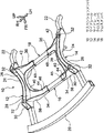
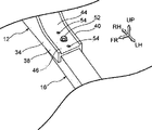
図1に示されるように、本実施形態のサスペンションメンバ10は、車体の前部に設けられたフロントサスペンションメンバである。このサスペンションメンバ10は、左右方向に間隔をあけて設けられた左右一対のサイドレール12、14と、左右一対のサイドレール12、14の前方側の部分及び後方側の部分を左右方向につなぐ前後一対のクロスメンバ16、18と、を備えている。なお、サスペンションメンバ10の前端部には、ロアバンパリインフォースメント20が接合されており、サスペンションメンバ10の後端部には、リヤブレース22が接合されている。
As shown in FIG. 1, the
右側のサイドレール12は、アルミダイキャスト製とされている。このサイドレール12は、車両前後方向に延在されていると共に上方側から見て車幅方向外側(右側)が凹状となるように湾曲されたサイドレール本体部24を備えている。このサイドレール本体部24は、車幅方向及び上下方向に沿って切断した断面視で略H状断面に形成されている。ここで、サイドレール本体部24における車幅方向外側の部分を外側壁部26とし、車幅方向内側の部分を内側壁部28とし、外側壁部26と内側壁部28とをつないでいる部分を接合壁部30とする。また、接合壁部30の前端部及び後端部には、サスペンションメンバ10を車体に固定するためのボルトが挿通される筒状のボス部32が立設されている。
The
サイドレール本体部24の前端部及び後端部からは、後述する前側のクロスメンバ16及び後側のクロスメンバ18がそれぞれ接合される前側クロスメンバ接合部34及び後側クロスメンバ接合部36が延出されている。この前側クロスメンバ接合部34及び後側クロスメンバ接合部36は、前後方向及び上下方向に沿って切断した断面視で略H状断面に形成されている。ここで、前側クロスメンバ接合部34の前側の部分を前側壁部38とし、前側クロスメンバ接合部34の後側の部分から後側クロスメンバ接合部36の前側の部分にかけての部分を中央壁部40とし、後側クロスメンバ接合部36の後側の部分を後側壁部42とする。また、前側壁部38と中央壁部40とをつなぐと共に、中央壁部40と後側壁部42とをつなぐ部分を平壁部44とする。
From the front end and the rear end of the side rail
左側のサイドレール14は、右側のサイドレール12と同様にアルミダイキャスト製とされている。なお、左側のサイドレール14の構成は、右側のサイドレール12の構成と車両中心線を挟んで車幅方向に対称に構成されている。そのため、左側のサイドレール14において右側のサイドレール12と対応する部分については当該右側のサイドレール12と同じ符号を付してその説明を省略する。
The
前側のクロスメンバ16及び後側のクロスメンバ18は、所定の長さに形成されたアルミニウム合金製の押し出し材である。このクロスメンバ16、18は、前後方向及び上下方向に沿って切断した断面視で矩形状の筒状断面に形成されている。前側のクロスメンバ16の右側の端部及び左側の端部は、右側のサイドレール12の前側クロスメンバ接合部34及び左側のサイドレール14の前側クロスメンバ接合部34にそれぞれ接合される接合部46とされている。また、後側のクロスメンバ18の右側の端部及び左側の端部は、右側のサイドレール12の後側クロスメンバ接合部36及び左側のサイドレール14の後側クロスメンバ接合部36にそれぞれ接合される接合部48とされている。
The
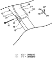
次に、本実施形態の要部である左右のサイドレール12、14と前後のクロスメンバ16、18との接合構造について説明する。なお、右側のサイドレール12の前側クロスメンバ接合部34と前側のクロスメンバ16の右側の接合部46との接合構造は、左側のサイドレール14の前側クロスメンバ接合部34と前側のクロスメンバ16の左側の接合部46との接合構造、右側のサイドレール12の後側クロスメンバ接合部36と後側のクロスメンバ18の右側の接合部48との接合構造、及び左側のサイドレール14の後側クロスメンバ接合部36と後側のクロスメンバ18の左側の接合部48との接合構造と同様の構造である。そのため、以下においては、右側のサイドレール12の前側クロスメンバ接合部34と前側のクロスメンバ16の右側の接合部46との接合構造について説明し、その他の部分の接合構造についての説明は省略する。
Next, the joining structure of the left and
図2Aには、右側のサイドレール12の前側クロスメンバ接合部34と前側のクロスメンバ16の右側の接合部46との接合部分を模式的に示した拡大斜視図が示されている。この図に示されるように、前側クロスメンバ接合部34の前側壁部38及び中央壁部40には、左右方向を長手方向とすると共に締結部材としてのボルト52が挿通される長孔50が形成されていると共に、前側のクロスメンバ16の右側の接合部46には、ボルト52が挿通される図示しない円形の孔が形成されている。そして、この長孔50等に挿通されたボルト52が締結部材としてのナット53に螺合されることで、右側のサイドレール12の前側クロスメンバ接合部34と前側のクロスメンバ16の右側の接合部46とが接合される。そして、本実施形態では、長孔50の内部におけるボルト52の位置を調節することで、左右のサイドレール12、14の左右方向への間隔が調節された状態で、左右のサイドレール12、14と前後のクロスメンバ16、18とが接合されるようになっている。
FIG. 2A shows an enlarged perspective view schematically showing a joint portion between the front cross member
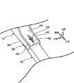
また、図2Bに示されるように、前側クロスメンバ接合部34の平壁部44及び前側のクロスメンバ16の右側の接合部46に、左右方向を長手方向とする長孔50を形成して、この長孔50等に挿通されたボルト52がナットに螺合されることで、右側のサイドレール12の前側クロスメンバ接合部34と前側のクロスメンバ16の右側の接合部46とが接合されていてもよい。当該構成は、エンジンマウント等の重量物を支える部材がクロスメンバ16、18に接合されている場合に有効である。
Further, as shown in FIG. 2B,
(本実施形態の作用並びに効果)
次に、本実施形態の作用並びに効果について説明する。
(Action and effect of this embodiment)
Next, the operation and effect of this embodiment will be described.
図1、図2A及び図2Bに示されるように、本実施形態のサスペンションメンバ10では、左右のサイドレール12、14の間に配置された前後のクロスメンバ16、18が、当該左右のサイドレール12、14にボルト52を介して接合されている。
As shown in FIGS. 1, 2A and 2B, in the
ここで、本実施形態では、長孔50の内部におけるボルト52の位置を調節することで、左右のサイドレール12、14の左右方向への間隔が調節された状態で、左右のサイドレール12、14と前後のクロスメンバ16、18とが接合される。これにより、左右のサイドレール12、14の左右方向への間隔が異なる車種においても、左右一対のサイドレール12、14及び前後のクロスメンバ16、18を共用することができる。
Here, in the present embodiment, by adjusting the position of the
また、本実施形態では、左右のサイドレール12、14が、アルミダイキャスト製とされている。これにより、当該左右のサイドレール12、14の形状自由度を高めることができる。その結果、一例として、左右のサイドレール12、14に他の部品が取付けられる被取付部を容易に設けることができる。また、被取付部の周縁部を補剛するために、当該周縁部を不要に厚くすること等が不要となり、左右のサイドレール12、14の重量の増加を抑制することができる。 Further, in the present embodiment, the left and right side rails 12 and 14 are made of die-cast aluminum. As a result, the degree of freedom in shape of the left and right side rails 12 and 14 can be increased. As a result, as an example, attached portions to which other parts can be attached can be easily provided on the left and right side rails 12 and 14. Further, in order to stiffen the peripheral edge portion of the mounted portion, it is not necessary to make the peripheral edge portion unnecessarily thick, and it is possible to suppress an increase in the weight of the left and right side rails 12 and 14.
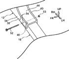
なお、本実施形態では、図2A及び図2Bに示されるように、長孔50の内部におけるボルト52の位置を調節することで、左右のサイドレール12、14の左右方向への間隔が調節された状態で、左右のサイドレール12、14と前後のクロスメンバ16、18とが接合される例について説明したが、本発明はこれに限定されない。例えば、図3A及び図3Bに示されるように、長孔50(図2A等参照)に代えて複数のボルト挿通孔54を形成し、ボルト52を挿通するボルト挿通孔54を選択することで、左右のサイドレール12、14の左右方向への間隔が調節されるように構成してもよい。
In the present embodiment, as shown in FIGS. 2A and 2B, by adjusting the position of the
また、本実施形態等では、長孔50及び複数のボルト挿通孔54をサイドレール12、14側に形成した例について説明したが、本発明はこれに限定されない。例えば、長孔50及び複数のボルト挿通孔54に対応する孔をクロスメンバ16、18側に形成してもよい。
Further, in the present embodiment and the like, an example in which the
また、本実施形態では、サスペンションメンバ10の前端部及び後端部に、ロアバンパリインフォースメント20及びリヤブレース22が接合されている例について説明したが、本発明はこれに限定されない。例えば、ロアバンパリインフォースメント20やリヤブレース22等が接合されないサスペンションメンバに本発明を適用することもできる。
Further, in the present embodiment, an example in which the
また、本実施形態では、フロントサスペンションメンバに本発明を適用した例について説明した例について説明したが、本発明はこれに限定されない。例えば、車両後部に設けられたリヤサスペンションメンバに本発明を適用することができる。 Further, in the present embodiment, an example in which the present invention is applied to the front suspension member has been described, but the present invention is not limited thereto. For example, the present invention can be applied to a rear suspension member provided at the rear of the vehicle.
以上、本発明の一実施形態について説明したが、本発明は、上記に限定されるものでなく、その主旨を逸脱しない範囲内において上記以外にも種々変形して実施することが可能であることは勿論である。 Although one embodiment of the present invention has been described above, the present invention is not limited to the above, and can be modified in various ways other than the above within a range not deviating from the gist thereof. Of course.
10 サスペンションメンバ
12 サイドレール
14 サイドレール
16 クロスメンバ
18 クロスメンバ
52 ボルト(締結部材)
53 ナット(締結部材)
10
53 Nut (fastening member)
Claims (3)
前記左右一対のサイドレールの間に配置され、締結部材を介して前記左右一対のサイドレールに接合されることで、前記左右一対のサイドレールの左右方向への間隔が調節可能とされたクロスメンバと、A cross member that is arranged between the pair of left and right side rails and is joined to the pair of left and right side rails via a fastening member so that the distance between the pair of left and right side rails in the left-right direction can be adjusted. When,
を備え、With
前記締結部材は、ボルトを含んでおり、The fastening member includes a bolt and
前記サイドレール及び前記クロスメンバには、前記ボルトが挿通される孔が形成され、A hole through which the bolt is inserted is formed in the side rail and the cross member.
前記サイドレール及び前記クロスメンバの少なくとも一方には、左右方向に間隔をあけて配置された複数の前記孔が形成されているサスペンションメンバ構造。A suspension member structure in which a plurality of the holes arranged at intervals in the left-right direction are formed on at least one of the side rail and the cross member.
前記孔は、前記第3壁部に形成されている請求項1に記載のサスペンションメンバ構造。The suspension member structure according to claim 1, wherein the hole is formed in the third wall portion.
前記孔は、前記第1壁部及び前記第2壁部に形成されている請求項1に記載のサスペンションメンバ構造。The suspension member structure according to claim 1, wherein the hole is formed in the first wall portion and the second wall portion.
Priority Applications (1)
| Application Number | Priority Date | Filing Date | Title |
|---|---|---|---|
| JP2017120340A JP6881069B2 (en) | 2017-06-20 | 2017-06-20 | Suspension member structure |
Applications Claiming Priority (1)
| Application Number | Priority Date | Filing Date | Title |
|---|---|---|---|
| JP2017120340A JP6881069B2 (en) | 2017-06-20 | 2017-06-20 | Suspension member structure |
Publications (2)
| Publication Number | Publication Date |
|---|---|
| JP2019001439A JP2019001439A (en) | 2019-01-10 |
| JP6881069B2 true JP6881069B2 (en) | 2021-06-02 |
Family
ID=65005450
Family Applications (1)
| Application Number | Title | Priority Date | Filing Date |
|---|---|---|---|
| JP2017120340A Expired - Fee Related JP6881069B2 (en) | 2017-06-20 | 2017-06-20 | Suspension member structure |
Country Status (1)
| Country | Link |
|---|---|
| JP (1) | JP6881069B2 (en) |
Families Citing this family (1)
| Publication number | Priority date | Publication date | Assignee | Title |
|---|---|---|---|---|
| KR20220133674A (en) * | 2021-03-25 | 2022-10-05 | 현대자동차주식회사 | Vehicle Body Frame Using Component Integration Type Rear Lower |
-
2017
- 2017-06-20 JP JP2017120340A patent/JP6881069B2/en not_active Expired - Fee Related
Also Published As
| Publication number | Publication date |
|---|---|
| JP2019001439A (en) | 2019-01-10 |
Similar Documents
| Publication | Publication Date | Title |
|---|---|---|
| CN102991584B (en) | The Front part body structure of vehicle | |
| KR101703596B1 (en) | Front vehicle body structure | |
| KR101786676B1 (en) | Front vehicle body structure | |
| JP6612991B2 (en) | Auto body structure | |
| JP6500768B2 (en) | Front body structure of the vehicle | |
| JP4751620B2 (en) | Body front structure | |
| JP6350461B2 (en) | Stabilizer support structure | |
| JP6565892B2 (en) | Vehicle front structure | |
| WO2017082125A1 (en) | Front sub-frame structure | |
| US8967671B2 (en) | Bolting structure of sub-frame | |
| JP6278030B2 (en) | Vehicle front structure | |
| CN108454700B (en) | Vehicle lower structure | |
| JP6299701B2 (en) | Vehicle lower structure | |
| JP2019177831A (en) | Front part vehicle body structure of vehicle | |
| CN106467134A (en) | Vehicle front body structure | |
| KR101575460B1 (en) | Front subframe for car body | |
| JP6881069B2 (en) | Suspension member structure | |
| JP6954212B2 (en) | Vehicle front body structure | |
| KR101689575B1 (en) | Connecting bracket of hood hinge mounting portions | |
| JP6891845B2 (en) | Vehicle front body structure | |
| JP6624493B2 (en) | Steering support member structure | |
| JP6508136B2 (en) | Vehicle front structure | |
| JP6287823B2 (en) | Suspension mounting structure | |
| JP6696444B2 (en) | Suspension member | |
| JP2016141315A (en) | Vehicle side structure |
Legal Events
| Date | Code | Title | Description |
|---|---|---|---|
| A621 | Written request for application examination |
Free format text: JAPANESE INTERMEDIATE CODE: A621 Effective date: 20190917 |
|
| A977 | Report on retrieval |
Free format text: JAPANESE INTERMEDIATE CODE: A971007 Effective date: 20200619 |
|
| A131 | Notification of reasons for refusal |
Free format text: JAPANESE INTERMEDIATE CODE: A131 Effective date: 20200714 |
|
| A521 | Request for written amendment filed |
Free format text: JAPANESE INTERMEDIATE CODE: A523 Effective date: 20200804 |
|
| A02 | Decision of refusal |
Free format text: JAPANESE INTERMEDIATE CODE: A02 Effective date: 20210112 |
|
| A521 | Request for written amendment filed |
Free format text: JAPANESE INTERMEDIATE CODE: A523 Effective date: 20210119 |
|
| C60 | Trial request (containing other claim documents, opposition documents) |
Free format text: JAPANESE INTERMEDIATE CODE: C60 Effective date: 20210119 |
|
| A911 | Transfer to examiner for re-examination before appeal (zenchi) |
Free format text: JAPANESE INTERMEDIATE CODE: A911 Effective date: 20210205 |
|
| C21 | Notice of transfer of a case for reconsideration by examiners before appeal proceedings |
Free format text: JAPANESE INTERMEDIATE CODE: C21 Effective date: 20210209 |
|
| TRDD | Decision of grant or rejection written | ||
| A01 | Written decision to grant a patent or to grant a registration (utility model) |
Free format text: JAPANESE INTERMEDIATE CODE: A01 Effective date: 20210406 |
|
| A61 | First payment of annual fees (during grant procedure) |
Free format text: JAPANESE INTERMEDIATE CODE: A61 Effective date: 20210419 |
|
| R151 | Written notification of patent or utility model registration |
Ref document number: 6881069 Country of ref document: JP Free format text: JAPANESE INTERMEDIATE CODE: R151 |
|
| LAPS | Cancellation because of no payment of annual fees |