JP6878052B2 - Rolling bearing with seal - Google Patents
Rolling bearing with seal Download PDFInfo
- Publication number
- JP6878052B2 JP6878052B2 JP2017045654A JP2017045654A JP6878052B2 JP 6878052 B2 JP6878052 B2 JP 6878052B2 JP 2017045654 A JP2017045654 A JP 2017045654A JP 2017045654 A JP2017045654 A JP 2017045654A JP 6878052 B2 JP6878052 B2 JP 6878052B2
- Authority
- JP
- Japan
- Prior art keywords
- seal
- bearing
- oil
- seal lip
- sliding surface
- Prior art date
- Legal status (The legal status is an assumption and is not a legal conclusion. Google has not performed a legal analysis and makes no representation as to the accuracy of the status listed.)
- Active
Links
- 238000005096 rolling process Methods 0.000 title claims description 34
- 229920001971 elastomer Polymers 0.000 claims description 10
- 238000007789 sealing Methods 0.000 claims description 5
- 239000000463 material Substances 0.000 claims description 3
- 239000003921 oil Substances 0.000 description 77
- 239000010687 lubricating oil Substances 0.000 description 36
- 230000005540 biological transmission Effects 0.000 description 11
- 239000002184 metal Substances 0.000 description 10
- 239000012530 fluid Substances 0.000 description 7
- 238000005461 lubrication Methods 0.000 description 7
- 230000002093 peripheral effect Effects 0.000 description 6
- 238000003756 stirring Methods 0.000 description 6
- 239000002245 particle Substances 0.000 description 5
- 239000000126 substance Substances 0.000 description 4
- 229920000459 Nitrile rubber Polymers 0.000 description 3
- 230000035699 permeability Effects 0.000 description 3
- 238000013459 approach Methods 0.000 description 2
- 230000000694 effects Effects 0.000 description 2
- 230000005489 elastic deformation Effects 0.000 description 2
- 230000001050 lubricating effect Effects 0.000 description 2
- 239000000843 powder Substances 0.000 description 2
- 230000002028 premature Effects 0.000 description 2
- 230000005855 radiation Effects 0.000 description 2
- 229920000800 acrylic rubber Polymers 0.000 description 1
- 238000010276 construction Methods 0.000 description 1
- 230000007423 decrease Effects 0.000 description 1
- 238000013461 design Methods 0.000 description 1
- 238000007599 discharging Methods 0.000 description 1
- 229920001973 fluoroelastomer Polymers 0.000 description 1
- 239000004519 grease Substances 0.000 description 1
- 238000002347 injection Methods 0.000 description 1
- 239000007924 injection Substances 0.000 description 1
- 238000000034 method Methods 0.000 description 1
- 239000000203 mixture Substances 0.000 description 1
- 238000012986 modification Methods 0.000 description 1
- 230000004048 modification Effects 0.000 description 1
- 239000004570 mortar (masonry) Substances 0.000 description 1
- 229920000058 polyacrylate Polymers 0.000 description 1
- 230000002265 prevention Effects 0.000 description 1
- 238000011160 research Methods 0.000 description 1
Images


Description
この発明は、シール付転がり軸受に係り、例えば、自動車、各種建設用機械等の車両に搭載されたトランスミッション内に用いられるシール付転がり軸受に関する。 The present invention relates to a rolling bearing with a seal, and relates to a rolling bearing with a seal used in a transmission mounted on a vehicle such as an automobile or various construction machines.
トランスミッション内には、ギヤの摩耗粉等の異物が混在する。この異物は軸受の転走面の早期剥離の原因となる。このため、シール部材により、軸受内部空間への異物侵入を防ぎ、転走面の早期剥離を防止することが行われている。 Foreign matter such as gear wear debris is mixed in the transmission. This foreign matter causes premature peeling of the rolling surface of the bearing. For this reason, the sealing member prevents foreign matter from entering the internal space of the bearing and prevents premature peeling of the rolling surface.
一般的なシール部材は、ゴム材料等で形成されたシールリップを有する。シール部材対して周方向に回転する軸受部品には、シールリップと滑り接触する摺動面が形成されている。シールリップと摺動面は全周に亘って滑り接触するため、シールリップの引き摺り抵抗(シールトルク)による軸受トルクの上昇を招くことになる。 A general sealing member has a sealing lip made of a rubber material or the like. The bearing component that rotates in the circumferential direction with respect to the seal member is formed with a sliding surface that slides into contact with the seal lip. Since the seal lip and the sliding surface slide into contact with each other over the entire circumference, the bearing torque increases due to the drag resistance (seal torque) of the seal lip.
このような軸受トルクの上昇を抑えるため、特許文献1には、シールリップの摺動部に突起を設け、くさび膜効果でオイルが摺動部に浸入することにより、シール部材と摺動面を流体潤滑油状態にして、低トルク化を図ることが提案されている。
In order to suppress such an increase in bearing torque,
また、軸受内部に潤滑に必要以上のオイルがある場合には、攪拌抵抗が増大し、このことも軸受トルクの上昇を招くことになる。しかし、上記した特許文献1においては、軸受内部に必要以上のオイルが入り込んだ場合については考慮されていない。
Further, if there is more oil than necessary for lubrication inside the bearing, the stirring resistance increases, which also causes an increase in the bearing torque. However, in the above-mentioned
この発明は、軸受内部に必要以上のオイルが入り込んだ場合においても攪拌抵抗が増加することがないシール付転がり軸受を提供することを課題とするものである。 An object of the present invention is to provide a rolling bearing with a seal in which the stirring resistance does not increase even when more oil than necessary enters the bearing.
前記の課題を解決するために、この発明は、外輪と、内輪と、前記外輪の内径面両端部に設けられた一対のシール嵌合溝に嵌合される外径部と、前記内輪と対向するシールリップを含む内径部とを有するシール部材と、を備え、前記シールリップと前記内輪との間に、軸受内部と軸受外部を連通する油通路が形成され、少なくとも一方の前記シール部材の前記外径部側に軸受内部と軸受外部を連通する油逃がし溝が形成されていることを特徴とする。 In order to solve the above-mentioned problems, the present invention presents an outer ring, an inner ring, an outer diameter portion fitted into a pair of seal fitting grooves provided at both ends of the inner diameter surface of the outer ring, and an outer diameter portion facing the inner ring. A seal member having an inner diameter portion including a seal lip is provided, and an oil passage communicating the inside of the bearing and the outside of the bearing is formed between the seal lip and the inner ring, and the seal member of at least one of the seal members is said to have an oil passage. An oil relief groove that communicates the inside of the bearing and the outside of the bearing is formed on the outer diameter side.
また、前記油逃がし溝が、外径部の周方向全周に亘って等間隔で配置すればよい。また、前記油逃がし溝が軸方向に対して斜めに設けることができる。そして、前記油逃がし溝が軸方向から視て円弧状に設けることができる。 Further, the oil relief grooves may be arranged at equal intervals over the entire circumference of the outer diameter portion in the circumferential direction. Further, the oil relief groove can be provided obliquely with respect to the axial direction. Then, the oil relief groove can be provided in an arc shape when viewed from the axial direction.
また、前記シールリップが前記内輪の摺動面と摺接し、前記シールリップの摺動部には、複数の突起が設けられ、前記油通路は、前記複数の突起間に形成されように構成することができる。 Further, the seal lip is in sliding contact with the sliding surface of the inner ring, a plurality of protrusions are provided on the sliding portion of the seal lip, and the oil passage is configured to be formed between the plurality of protrusions. be able to.
また、前記外径部は、ゴム材で形成すればよい。 Further, the outer diameter portion may be formed of a rubber material.
以上のように、この発明は、シール付転がり軸受において、少なくとも一方のシール部材の外径側に軸受内部と軸受外部を連通する油逃がし溝が形成されていることにより、軸受内部に必要以上に入り込んだ潤滑油を油逃がし溝から軸受外部に排出することができ、攪拌抵抗の増加を防止することができる。 As described above, in the rolling bearing with a seal, the oil relief groove that communicates the inside of the bearing and the outside of the bearing is formed on the outer diameter side of at least one of the seal members, so that the inside of the bearing is unnecessarily. The lubricating oil that has entered can be discharged from the oil relief groove to the outside of the bearing, and an increase in stirring resistance can be prevented.
以下、この発明の実施形態を添付図面に基づいて説明する。
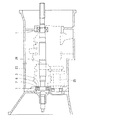
図1から図3に示すように、シール付転がり軸受(以下、単に転がり軸受とも呼ぶこともある)1は、外輪2と、内輪3と、その外輪2の内径面に形成された軌道溝4と内輪3の外径面に形成された軌道溝5間に組込まれた複数のボール6およびそのボール6を保持する保持器7からなる。すなわち、本実施形態の転がり軸受1は、玉軸受である。
Hereinafter, embodiments of the present invention will be described with reference to the accompanying drawings.
As shown in FIGS. 1 to 3, the rolling bearing 1 with a seal (hereinafter, also simply referred to as a rolling bearing) 1 includes an
以下、転がり軸受1の軸受中心軸に沿った方向を軸方向、軸方向に直交する方向を径方向という。また、軸受中心軸回りの円周方向を周方向という。
Hereinafter, the direction along the bearing central axis of the rolling
外輪2及び内輪3によって形成される環状の軸受内部には、グリース、オイルバス等の適宜の手段により、潤滑油が供給される。
Lubricating oil is supplied to the inside of the annular bearing formed by the
この発明の実施形態に係るシール付転がり軸受1は、例えば、自動車のトランスミッション内に用いられる。図10は、自動車のトランスミッションに組み込んだ一例を示す概略図である。同図はオートマチックトランスミッションの例である。ケース23の軸方向両端にシール付転がり軸受1、1の各外輪2が嵌合され、これら軸受1、1の内輪3に、メインシャフト24の両端がそれぞれ回転自在に支持されている。ケース23に、カウンターシャフト25が前記メインシャフト24と平行に設けられている。このカウンターシャフト25は、メインシャフト24のギヤ部に噛み合うギヤ部を有し、前記ケース23に軸受を介して回転自在に支持されている。
The rolling bearing 1 with a seal according to the embodiment of the present invention is used, for example, in a transmission of an automobile. FIG. 10 is a schematic view showing an example incorporated in a transmission of an automobile. The figure is an example of an automatic transmission. The
尚、この発明の実施形態のシール付転がり軸受1は、車両のトランスミッション以外に、ディファレンシャル、等速ジョイント、プロペラシャフト、ターボチャージャ、工作機械等の軸受に用いられ、これらの回転軸に取り付けられる。 The rolling bearing 1 with a seal according to the embodiment of the present invention is used for bearings of differentials, constant velocity joints, propeller shafts, turbochargers, machine tools, etc., in addition to vehicle transmissions, and is attached to these rotating shafts.
上記したように、内輪3は、メインシャフト24(図10参照)に取り付けられ、メインシャフト24と一体に回転する。外輪2は、ケース23(図10参照)に取り付けられる。
As described above, the
外輪2の内径面には、軸方向の両端部に一対のシール嵌合溝8が形成され、一方、内輪3の外径面には、上記一対のシール嵌合溝8と半径方向で対向する位置にシール溝9が形成されている。
A pair of
外輪2に形成された一対のシール嵌合溝8のそれぞれには、ゴム製のシール部材10の外径部11が嵌合されている。シール部材10は、芯金10bと芯金10bを覆うゴム製部分10aとからなる。具体的には、ゴム製部分10aは、芯金10bの軸方向内側面を除く芯金10b全体を覆っている。ゴム製部分10aは、ニトリルゴム、耐熱ニトリルゴム、水素添加ニトリルゴム、アクリルゴム、フッ素ゴム等の耐油性や耐熱性に優れたゴムを素材としている。
The
このシール部材10は、軸受内部と軸受外部を区切る。シール部材10を境界とした外部側には、ギヤの摩耗粉、クラッチの摩耗粉、微小採石等、転がり軸受1の組み込み先に応じた異物が存在する。このような粉状の異物は、潤滑油や雰囲気の流れによって転がり軸受1付近に到達する。シール部材10は、軸受外部から軸受内部へ異物の侵入を防止する。
The
上記したように、シール部材10は、シール嵌合溝8に圧入される外径部11と、内周側で外向きのラジアルシールリップ13と内向きのアキシャルシールリップ14とを内径部に有する。シール部材10は、外径部11をシール嵌合溝8に圧入することにより、外輪2に取り付けられる。
As described above, the
図3及び図4に示すように、シール部材10のラジアルシールリップ13は、シール溝9の軸方向外方に形成された小径の円筒面からなる摺動面31に弾性接触し、一方、アキシャルシールリップ14の先端はシール溝9の内側面の摺動面32に弾性接触している。ラジアルシールリップ13及び摺動面31間に径方向に締め代が形成され、アキシャルシールリップ14及びシール溝9の内側面の摺動面32には、軸方向に締め代が形成されている。これら締め代により、ゴム状弾性の変形を生じて、軸受空間を密閉している。
As shown in FIGS. 3 and 4, the
ラジアルシールリップ13の摺動面31に対する接触面には、全体に亘って微小な突起15が設けられ、また、アキシャルシールリップ14のシール溝9の内側面の摺動面32に対する接触面にも全体に亘って微小な突起17が設けられている。
The contact surface of the
図4から図8に示すように、ラジアルシールリップ13は、摺動面31との直交方向、即ち摺動面31に接する接線に垂直な法線方向に突出高さを持った突起15を有する。摺動面31が軸受中心軸を中心とした円筒面状なので、これとの直交方向は、径方向に相当する。突起15は、ラジアルシールリップ13の先端から摺動面31と径方向に対面し得る範囲の全域に亘って形成されている。摺動面31に接触する突起15を境とした両側において、連通する油通路16が生じる。
As shown in FIGS. 4 to 8, the
図4、図6から図8に示すように、アキシャルシールリップ14は、シール溝9の内側面の摺動面32との直交方向、即ち摺動面32に接する接線に垂直な法線方向に突出高さを持った突起17を有する。摺動面32が軸受中心軸を中心としたすり鉢状なので、これとの直交方向は、軸方向から所定角度傾斜した方向となる。突起17は、アキシャルシールリップ14の先端から摺動面32と軸方向に対面する範囲の全域に亘って形成されている。摺動面32に接触する突起17を境とした両側において、連通する油通路18が生じる。
As shown in FIGS. 4 and 6 to 8, the
油通路16と油通路18とにより、軸受内部と軸受外部とが連通されることになる。
The inside of the bearing and the outside of the bearing are communicated with each other by the
ラジアルシールリップ13の突起15は、周方向全周に亘って均一間隔で配置されている。このため、油通路16も周方向全周に亘って均一間隔で生じる。突起15が全周に亘って分散配置され、ラジアルシールリップ13は突起15において、摺動面31と摺動接触する。また、アキシャルシールリップ14の突起17は、周方向全周に亘って均一間隔で配置されている。このため、油通路18も周方向全周に亘って均一間隔で生じる。突起17が全周に亘って分散配置され、アキシャルシールリップ14は突起17において、摺動面32と摺動接触する。
The
油通路16は、概ね摺動面31に沿った溝状で軸受内部のシール溝9と外部空間を連通し、油通路18は、シール溝9と軸受内部を連通する。オイルバス、又は、はね掛けの場合、図4の破線の矢印Aで示すように、潤滑油は外部から油通路16、18を通って軸受内部に至り、遠心力により外輪2側へ送られる。
The
図5は、シール部材10のラジアルシールリップ13付近を拡大して断面で示している。この断面は、ラジアルシールリップ13と摺動面31との間における摺動面との直交方向の隙間を示している。
FIG. 5 shows an enlarged cross section of the vicinity of the
図5に示すように、ラジアルシールリップ13と摺動面31間の締め代に基づいてラジアルシールリップ13が弾性変形することで生じる緊迫力や潤滑油の油圧により、突起15に実質的な変形が生じないようになっている。
As shown in FIG. 5, the
ラジアルシールリップ13は、自然状態においてラジアルシールリップ13の内径を規定する先端を有する。突起15は、ラジアルシールリップ13の先端まで及んでおり、摺動面31との間に径方向の締め代を持った範囲の全域に亘って形成されている。
The
突起15は、周方向に一定の間隔dで並んでいる。ラジアルシールリップ13を軸方向から見た外観で考えると、複数の突起15が間隔dに対応した一定のピッチ角度θで周方向に配置された放射状になって現れている。なお、放射中心は、図外のシール部材10の中心軸上にある。
The
各突起15がラジアルシールリップ13の先端付近に存在することにより、ラジアルシールリップ13が各突起15で摺動面31と摺動接触し、各突起15、15間に油通路16が生じる。
Since each
突起15は、周方向wの両端から周方向の中央に向かって次第に摺動面に接近するR形状となっている。このR形状は突起15の放射方向の全長亘って与えられている。このため、突起15と摺動面31とが接触する領域は、突起15の周方向の中央に存在する。
The
ラジアルシールリップ13に対して摺動面31が相対的に矢印A方向に回転すると、油通路16内の潤滑油が突起15と摺動面31との楔状の隙間に引き込まれる。前述の楔状の隙間における楔角度は、引き込まれる潤滑油が存在する広大側の油通路16から狭小側に向かって次第に小さくなることから、突起15と摺動面31とが摺動接触する線状領域に近いところほど楔効果が強く生じる。従って、その線状領域での油膜の油圧をより効果的に高め、突起15を摺動面31から完全に離れさせ、その線状領域での油膜を厚く生じさせることができ、突起15と摺動面31との間の潤滑状態を流体潤滑状態とすることが容易となる。
When the sliding
ここで、突起15と摺動面31との間を完全に分離させる油膜があれば、突起15に対して摺動面31が直接接触しない状態で摺動する流体潤滑状態となる。このような油膜を各突起15と摺動面31との間で保つことにより、ラジアルシールリップ13及び摺動面31の間を流体潤滑状態とすることができる。
Here, if there is an oil film that completely separates the
図7及び図8に示すように、ラジアルシールリップ13と同様に、アキシャルシールリップ14の先端から摺動面32と軸方向に対面する範囲の全域に亘って突起17が形成されている。摺動面32に接触する突起17を境とした両側において、連通する油通路18が生じる。この突起17もラジアルシールリップ13の突起15と同様に、周方向に一定の間隔で並び、複数の突起17が間隔に対応した一定のピッチ角度で周方向に配置された放射状になって形成されている。なお、放射中心は、図外のシール部材10の中心軸上にある。
As shown in FIGS. 7 and 8, as in the
各突起17がアキシャルシールリップ14の先端付近に存在することにより、各突起17で摺動面32と摺動接触し、各突起17、17間に油通路18が生じる。この突起17もラジアルシールリップ13の突起15と同様に、周方向の両端から周方向の中央に向かって次第に摺動面に接近するR形状とし、このR形状は突起17の放射方向の全長に亘って形成すればよい。
Since each
このように、アキシャルシールリップ14の先端に突起17を設けることにより、ラジアルシールリップ13と同様に、アキシャルシールリップ14のシール溝9の摺動面32との間を流体潤滑状態とすることができる。
In this way, by providing the
上記したように、オイルバス、又は、はね掛けの場合、図4の破線の矢印Aで示すように、潤滑油は軸受外部から油通路16、18を通って軸受内部に引き込まれ、ラジアルシールリップ13、アキシャルシールリップ14とも流体潤滑状態として、シールトルクの低減を図ることができる。
As described above, in the case of an oil bath or a splash, as shown by the broken arrow A in FIG. 4, the lubricating oil is drawn from the outside of the bearing through the
この実施形態におけるシール付転がり軸受1は、車両のトランスミッションに用いることを想定している。車両のトランスミッション内に存在するシール付転がり軸受への給油は、はね掛け、オイルバス、ノズル噴射等の方法によって行われる。このため、シール付転がり軸受に固定されるシール部材のシールリップ周辺には潤滑油が存在している。給油される潤滑油は、トランスミッション内に存在するギヤ等の他の潤滑部分でも共通に用いられる。その潤滑油は、オイルポンプで循環されており、その循環経路に設けられたオイルフィルタで濾過される。
The rolling
特許文献1に記載されているように、車両のトランスミッションやディファレンシャルギヤ等の駆動系の回転部支持に用いられるシール付軸受に対して、オイルフィルタで濾過される潤滑油を給油する場合、粒径50μmを超えるような大きな異物が軸受内部へ浸入することをシール部材10で防止する限り、潤滑油に含まれる粒径50μm以下の異物が軸受内部に侵入することを許容しても軸受寿命に問題は起こさない。本願出願人の研究により、突起15、17の高さを0.07mm以下に設定すれば、粒径50μmを超える異物が容易に通過できないような狭い隙間(油通路を含む)をシールリップとシール摺動面間に生じさせることができることがわかった。そこで、この実施形態におけるラジアルシールリップ13に形成される油通路16、アキシャルシールリップ14に形成される油通路18の大きさを70μm以下にするとよい。
As described in
この実施形態では、突起15、17の高さhは、0.07mm以下に設定しており、具体的には0.05mmに設定している。この高さhは、設計上、摺動面31又は32と接触し得る範囲において最も高い位置での値である。この位置は、各突起15、17と摺動面との間に設定された締め代が最大になるところでもある。軸受運転中の突起の変形量は無視できるから、シールリップ13(14)と摺動面31(32)との間における摺動面との直交方向の隙間(油通路を含む)は、摺動面との直交方向の最も狭いところで突起15、17の高さhに相当の高さになり、実質0.05mmを超えない。このため、粒径50μmを超える異物が外部の潤滑油に含まれていても、その異物が油通路16、18を通過することは略起こらないと考えられる。
In this embodiment, the heights h of the
尚、シール付転がり軸受1の早期破損の原因となる摩耗粉は、粒径0.3mmを超える異物として仮定すれば、突起15、17の突出高さを0.3mm以下に設定すればよい。また、油通路16、18の通油性を良好にするためには、突起15、17の突出高さは、0.05mm以上にすればよい。油通路16、18の通油性や異物の通過を防止する観点から突起15、17の突出高さは適宜選択すればよい。
Assuming that the wear debris that causes early breakage of the rolling
上記したように、オイルバス、又は、はね掛けにより、図4の破線の矢印Aで示すように、潤滑油は外部から油通路16、18を通って軸受内部に引き込まれる。この潤滑油の流入により、シールリップ13、14と摺動面31、32との間は流体潤滑状態になり、低トルクを図ることができる。しかし、軸受内部に必要以上に潤滑油が入り込むと攪拌抵抗が増加する。一度軸受内部に入り込んだ潤滑油は遠心力により外輪2側へ送られ、外輪2側に滞留することになる。
As described above, the lubricating oil is drawn into the bearing from the outside through the
そこで、この実施形態では、シール部材10の外径部11の外周面側に軸受内部と軸受外部を連通する油逃がし溝12を形成している。図6及び図7に示すように、外径部11に複数の油逃がし溝12が周方向全周に亘って等間隔で設けられている。なお、油逃がし溝12は、不等間隔で設けられていてもよい。この油逃がし溝12は、シール部材10の内周側は深く外周側に向かって浅くなるように形成されている。この実施形態では、遠心力で外輪側へ送られた潤滑油が図4の矢印Bに示すように、この油逃がし溝12から軸受外部へ排出する。このように、外径部11側に複数の油逃がし溝12を設けることで、必要以上に流入した潤滑油を排出して、外輪側に潤滑油が滞留することを抑制し、攪拌抵抗が増加することを抑制する。
Therefore, in this embodiment, an
この油逃がし溝12は、図2、図6に示すように、遠心力により外輪2側に送られてきた潤滑油を逃がしやすいように、軸方向に対して斜めに設けられ、この実施形態では、油逃がし溝12が円弧状に形成されている。
As shown in FIGS. 2 and 6, the
この油逃がし溝12の幅は軸受内部側を広く、軸受外部側に行くにつれて狭くなるように形成している。このように油逃がし溝12の幅を変えることにより、潤滑油は軸受外部に排出しやすくし、軸受内部への異物が流入することを抑制することができる。
The width of the
そして、図4に示すように、シール嵌合穴8にシール部材10の外径部11を嵌合させて取り付けた際に、軸受の外輪2とシール部材10との間に位置する油逃がし溝12の径方向の間隔gが0.05mm以上0.3mm以下にすることが好ましい。この油逃がし溝12は、潤滑油を排出することが主たる用途であるが、回転軸が回転していない時に、潤滑油が軸受外部から油逃がし溝12に到達した場合などに、この油逃がし溝12から軸受内部に潤滑油が流入する。無回転から回転に移行する際には初期潤滑のための潤滑油は必要となるため、無回転時に油逃がし溝12から潤滑油が入ることで初期動作時の潤滑油が不足を改善することができる。しかし、潤滑油と共に異物が入りこむことは好ましくない。そこで、この油逃がし溝12から異物が入り込まないように、外輪2側に臨む油逃がし溝12を前述したシールリップ13、14の突起15、17と同様に、通油性と異物の混入を考慮して0.05mm以上0.3mm以下になるように、外径部11の内周側から外周側に向かうに連れて深さを浅く、幅を狭くした形状に形成している。
Then, as shown in FIG. 4, when the
上記した実施形態においては、シール部材10のラジアルシールリップ13は、シール溝9の軸方向外方に形成された小径の円筒面からなる摺動面31に弾性接触し、一方、アキシャルシールリップ14の先端はシール溝9の内側面の摺動面32に弾性接触している。図9に示す他の実施形態に示すシール部材10においては、内輪3側に設けられるシールリップ19は内輪3の外径面とは接触しない非接触型のシール部材である。シールリップ19と内輪3の外径面との間に油通路が形成され、潤滑油が矢印Aで示すように、軸受内部に流入し、遠心力で外輪側へ送られた潤滑油が矢印Bに示すように、この油逃がし溝12から軸受外部へ排出する。このように、必要以上に流入した潤滑油を排出して、外輪側に潤滑油が滞留することを抑制し、攪拌抵抗が増加することを抑制する。
In the above embodiment, the
上記した実施形態においては、シール部材10は芯金10bと芯金10bを覆うゴム製部分10aで形成しているが、シール部材10を金属板で形成した金属シール板でもよい。この金属シール板の軸受嵌合部に嵌合させる外径部に切り溝を形成して、潤滑油を排出するように構成すればよい。
In the above-described embodiment, the
また、上記した実施形態においては、一対のシール部材10の外径部11に油逃がし溝12を設けているが、どちらか一方のシール部材10に設けるだけでもよい。
Further, in the above-described embodiment, the
この発明は前述した実施形態に何ら限定されるものではなく、この発明の要旨を逸脱しない範囲において、さらに種々の形態で実施し得ることは勿論のことであり、本発明の範囲は、特許請求の範囲によって示され、さらに特許請求の範囲に記載の均等の意味、および範囲内の全ての変更を含む。 The present invention is not limited to the above-described embodiments, and it goes without saying that the present invention can be carried out in various forms without departing from the gist of the present invention. Indicated by the scope of, and further include the equal meaning described in the claims, and all modifications within the scope.
1 :シール付転がり軸受
2 :外輪
3 :内輪
4 :軌道溝
5 :軌道溝
6 :ボール
7 :保持器
8 :シール嵌合溝
9 :シール溝
10 :シール部材
10a :ゴム製部分
10b :芯金
11 :外径部
12 :油逃がし溝
13 :ラジアルシールリップ
14 :アキシャルシールリップ
15 :突起
16 :油通路
17 :突起
18 :油通路
19 :シールリップ
31 :摺動面
32 :摺動面
1: Rolling bearing with seal 2: Outer ring 3: Inner ring 4: Raceway groove 5: Raceway groove 6: Ball 7: Cage 8: Seal fitting groove 9: Seal groove 10:
Claims (6)
前記シールリップと前記内輪との間に、軸受内部と軸受外部を連通する油通路が形成され、
少なくとも一方の前記シール部材の前記外径部側に軸受内部と軸受外部を連通する油逃がし溝が形成され、
この油逃がし溝の幅を、軸受内部側を広く、軸受外部側に行くにつれて狭くなるように形成したことを特徴とするシール付転がり軸受。 A seal member having an outer ring, an inner ring, an outer diameter portion fitted into a pair of seal fitting grooves provided at both ends of the inner diameter surface of the outer ring, and an inner diameter portion including a seal lip facing the inner ring. , With
An oil passage communicating the inside of the bearing and the outside of the bearing is formed between the seal lip and the inner ring.
An oil relief groove that communicates the inside of the bearing and the outside of the bearing is formed on the outer diameter side of at least one of the sealing members .
A rolling bearing with a seal, characterized in that the width of the oil relief groove is formed so as to widen the inner side of the bearing and narrow it toward the outer side of the bearing.
前記シールリップの摺動部には、複数の突起が設けられ、
前記油通路は、前記複数の突起間に形成されることを特徴とする請求項1〜4のいずれか1項に記載のシール付転がり軸受。 The seal lip is in sliding contact with the sliding surface of the inner ring,
A plurality of protrusions are provided on the sliding portion of the seal lip.
The rolling bearing with a seal according to any one of claims 1 to 4, wherein the oil passage is formed between the plurality of protrusions.
Priority Applications (1)
| Application Number | Priority Date | Filing Date | Title |
|---|---|---|---|
| JP2017045654A JP6878052B2 (en) | 2017-03-10 | 2017-03-10 | Rolling bearing with seal |
Applications Claiming Priority (1)
| Application Number | Priority Date | Filing Date | Title |
|---|---|---|---|
| JP2017045654A JP6878052B2 (en) | 2017-03-10 | 2017-03-10 | Rolling bearing with seal |
Publications (2)
| Publication Number | Publication Date |
|---|---|
| JP2018150953A JP2018150953A (en) | 2018-09-27 |
| JP6878052B2 true JP6878052B2 (en) | 2021-05-26 |
Family
ID=63680260
Family Applications (1)
| Application Number | Title | Priority Date | Filing Date |
|---|---|---|---|
| JP2017045654A Active JP6878052B2 (en) | 2017-03-10 | 2017-03-10 | Rolling bearing with seal |
Country Status (1)
| Country | Link |
|---|---|
| JP (1) | JP6878052B2 (en) |
Family Cites Families (3)
| Publication number | Priority date | Publication date | Assignee | Title |
|---|---|---|---|---|
| JPS5463843U (en) * | 1977-10-14 | 1979-05-07 | ||
| JP2006266496A (en) * | 2005-02-28 | 2006-10-05 | Nsk Ltd | Rolling bearing and bearing device |
| WO2016143786A1 (en) * | 2015-03-09 | 2016-09-15 | Ntn株式会社 | Sealed bearing |
-
2017
- 2017-03-10 JP JP2017045654A patent/JP6878052B2/en active Active
Also Published As
| Publication number | Publication date |
|---|---|
| JP2018150953A (en) | 2018-09-27 |
Similar Documents
| Publication | Publication Date | Title |
|---|---|---|
| JP6523994B2 (en) | Sealed bearing | |
| CN108119560B (en) | Rolling bearing with improved sealing device | |
| WO2016143786A1 (en) | Sealed bearing | |
| JP6773425B2 (en) | Bearing with seal | |
| JP2018040445A (en) | Bearing with seal | |
| US11300155B2 (en) | Cage for a tapered roller bearing and tapered roller bearing | |
| JP7201752B2 (en) | Sealed bearing | |
| JP7050636B2 (en) | Ball bearings | |
| JP2018119580A (en) | Creep preventive rolling bearing | |
| JP6786265B2 (en) | Bearing with seal | |
| JP6745609B2 (en) | Bearing with seal | |
| JP6878052B2 (en) | Rolling bearing with seal | |
| JP7240975B2 (en) | Sealed bearing | |
| WO2017150609A1 (en) | Seal-equipped bearing, and ball bearing | |
| WO2017150544A1 (en) | Bearing with seal | |
| JP6797719B2 (en) | Oil seal and bearing with seal | |
| JP5146189B2 (en) | Rolling bearing | |
| US20090028486A1 (en) | Tapered roller bearing | |
| JP2005188679A (en) | Ball bearing | |
| JP6887046B2 (en) | Tapered roller bearing | |
| JP2018197586A (en) | Rolling bearing with seal | |
| JP6725264B2 (en) | Tapered roller bearing | |
| WO2022202545A1 (en) | Bearing with seal | |
| WO2022181437A1 (en) | Seal-attached bearing | |
| JP6745608B2 (en) | Ball bearing |
Legal Events
| Date | Code | Title | Description |
|---|---|---|---|
| A621 | Written request for application examination |
Free format text: JAPANESE INTERMEDIATE CODE: A621 Effective date: 20200226 |
|
| A131 | Notification of reasons for refusal |
Free format text: JAPANESE INTERMEDIATE CODE: A131 Effective date: 20210202 |
|
| A521 | Request for written amendment filed |
Free format text: JAPANESE INTERMEDIATE CODE: A523 Effective date: 20210324 |
|
| TRDD | Decision of grant or rejection written | ||
| A01 | Written decision to grant a patent or to grant a registration (utility model) |
Free format text: JAPANESE INTERMEDIATE CODE: A01 Effective date: 20210406 |
|
| A61 | First payment of annual fees (during grant procedure) |
Free format text: JAPANESE INTERMEDIATE CODE: A61 Effective date: 20210428 |
|
| R150 | Certificate of patent or registration of utility model |
Ref document number: 6878052 Country of ref document: JP Free format text: JAPANESE INTERMEDIATE CODE: R150 |
|
| R250 | Receipt of annual fees |
Free format text: JAPANESE INTERMEDIATE CODE: R250 |