JP6876216B2 - Bamboo nitrogen-containing carbon nanotubes, bamboo nitrogen-containing carbon nanotube manufacturing equipment, and bamboo nitrogen-containing carbon nanotube manufacturing methods - Google Patents
Bamboo nitrogen-containing carbon nanotubes, bamboo nitrogen-containing carbon nanotube manufacturing equipment, and bamboo nitrogen-containing carbon nanotube manufacturing methods Download PDFInfo
- Publication number
- JP6876216B2 JP6876216B2 JP2016018339A JP2016018339A JP6876216B2 JP 6876216 B2 JP6876216 B2 JP 6876216B2 JP 2016018339 A JP2016018339 A JP 2016018339A JP 2016018339 A JP2016018339 A JP 2016018339A JP 6876216 B2 JP6876216 B2 JP 6876216B2
- Authority
- JP
- Japan
- Prior art keywords
- nitrogen
- bamboo
- containing carbon
- tubular body
- electrode
- Prior art date
- Legal status (The legal status is an assumption and is not a legal conclusion. Google has not performed a legal analysis and makes no representation as to the accuracy of the status listed.)
- Expired - Fee Related
Links
- OKTJSMMVPCPJKN-UHFFFAOYSA-N Carbon Chemical compound [C] OKTJSMMVPCPJKN-UHFFFAOYSA-N 0.000 title claims description 68
- 239000002041 carbon nanotube Substances 0.000 title claims description 59
- 229910021393 carbon nanotube Inorganic materials 0.000 title claims description 58
- QJGQUHMNIGDVPM-UHFFFAOYSA-N nitrogen group Chemical group [N] QJGQUHMNIGDVPM-UHFFFAOYSA-N 0.000 title claims description 58
- 238000004519 manufacturing process Methods 0.000 title claims description 21
- 235000017166 Bambusa arundinacea Nutrition 0.000 title claims description 20
- 235000017491 Bambusa tulda Nutrition 0.000 title claims description 20
- 241001330002 Bambuseae Species 0.000 title claims description 20
- 235000015334 Phyllostachys viridis Nutrition 0.000 title claims description 20
- 239000011425 bamboo Substances 0.000 title claims description 20
- IJGRMHOSHXDMSA-UHFFFAOYSA-N Atomic nitrogen Chemical compound N#N IJGRMHOSHXDMSA-UHFFFAOYSA-N 0.000 claims description 49
- 238000006243 chemical reaction Methods 0.000 claims description 34
- 229910052757 nitrogen Inorganic materials 0.000 claims description 28
- 239000012530 fluid Substances 0.000 claims description 23
- 125000004433 nitrogen atom Chemical group N* 0.000 claims description 21
- 229910001873 dinitrogen Inorganic materials 0.000 claims description 17
- 230000004888 barrier function Effects 0.000 claims description 12
- 229910052751 metal Inorganic materials 0.000 claims description 9
- 239000002184 metal Substances 0.000 claims description 9
- 150000003623 transition metal compounds Chemical class 0.000 claims description 8
- 239000003575 carbonaceous material Substances 0.000 claims description 5
- 230000007423 decrease Effects 0.000 claims description 4
- 229910002804 graphite Inorganic materials 0.000 claims description 4
- 239000010439 graphite Substances 0.000 claims description 4
- 238000001556 precipitation Methods 0.000 claims description 2
- 150000002902 organometallic compounds Chemical class 0.000 claims 2
- 239000007789 gas Substances 0.000 description 30
- XKRFYHLGVUSROY-UHFFFAOYSA-N Argon Chemical compound [Ar] XKRFYHLGVUSROY-UHFFFAOYSA-N 0.000 description 22
- 229910052786 argon Inorganic materials 0.000 description 11
- 238000004458 analytical method Methods 0.000 description 8
- 238000010586 diagram Methods 0.000 description 8
- 230000005540 biological transmission Effects 0.000 description 6
- 239000006230 acetylene black Substances 0.000 description 5
- 229910052799 carbon Inorganic materials 0.000 description 5
- 238000005259 measurement Methods 0.000 description 5
- 238000004611 spectroscopical analysis Methods 0.000 description 5
- 239000000126 substance Substances 0.000 description 5
- 150000001721 carbon Chemical group 0.000 description 4
- 238000010894 electron beam technology Methods 0.000 description 4
- 239000007788 liquid Substances 0.000 description 4
- 238000000034 method Methods 0.000 description 4
- 238000003917 TEM image Methods 0.000 description 3
- 238000005229 chemical vapour deposition Methods 0.000 description 3
- 238000002149 energy-dispersive X-ray emission spectroscopy Methods 0.000 description 3
- 238000010438 heat treatment Methods 0.000 description 3
- 239000000203 mixture Substances 0.000 description 3
- 239000012778 molding material Substances 0.000 description 3
- 239000000523 sample Substances 0.000 description 3
- XEEYBQQBJWHFJM-UHFFFAOYSA-N Iron Chemical compound [Fe] XEEYBQQBJWHFJM-UHFFFAOYSA-N 0.000 description 2
- PNEYBMLMFCGWSK-UHFFFAOYSA-N aluminium oxide Inorganic materials [O-2].[O-2].[O-2].[Al+3].[Al+3] PNEYBMLMFCGWSK-UHFFFAOYSA-N 0.000 description 2
- 238000000921 elemental analysis Methods 0.000 description 2
- 239000001307 helium Substances 0.000 description 2
- 229910052734 helium Inorganic materials 0.000 description 2
- SWQJXJOGLNCZEY-UHFFFAOYSA-N helium atom Chemical compound [He] SWQJXJOGLNCZEY-UHFFFAOYSA-N 0.000 description 2
- 238000013507 mapping Methods 0.000 description 2
- 229910052594 sapphire Inorganic materials 0.000 description 2
- 239000010980 sapphire Substances 0.000 description 2
- 238000012916 structural analysis Methods 0.000 description 2
- KMHSUNDEGHRBNV-UHFFFAOYSA-N 2,4-dichloropyrimidine-5-carbonitrile Chemical compound ClC1=NC=C(C#N)C(Cl)=N1 KMHSUNDEGHRBNV-UHFFFAOYSA-N 0.000 description 1
- 125000004429 atom Chemical group 0.000 description 1
- 230000015572 biosynthetic process Effects 0.000 description 1
- 125000004432 carbon atom Chemical group C* 0.000 description 1
- 239000003054 catalyst Substances 0.000 description 1
- 235000013365 dairy product Nutrition 0.000 description 1
- 230000000694 effects Effects 0.000 description 1
- 238000010891 electric arc Methods 0.000 description 1
- 238000002003 electron diffraction Methods 0.000 description 1
- 238000000295 emission spectrum Methods 0.000 description 1
- 230000005281 excited state Effects 0.000 description 1
- KTWOOEGAPBSYNW-UHFFFAOYSA-N ferrocene Chemical compound [Fe+2].C=1C=C[CH-]C=1.C=1C=C[CH-]C=1 KTWOOEGAPBSYNW-UHFFFAOYSA-N 0.000 description 1
- 239000000446 fuel Substances 0.000 description 1
- 238000002347 injection Methods 0.000 description 1
- 239000007924 injection Substances 0.000 description 1
- 239000003273 ketjen black Substances 0.000 description 1
- 239000000463 material Substances 0.000 description 1
- 230000002093 peripheral effect Effects 0.000 description 1
- IEQIEDJGQAUEQZ-UHFFFAOYSA-N phthalocyanine Chemical compound N1C(N=C2C3=CC=CC=C3C(N=C3C4=CC=CC=C4C(=N4)N3)=N2)=C(C=CC=C2)C2=C1N=C1C2=CC=CC=C2C4=N1 IEQIEDJGQAUEQZ-UHFFFAOYSA-N 0.000 description 1
- 239000000843 powder Substances 0.000 description 1
- 239000002244 precipitate Substances 0.000 description 1
- 238000000851 scanning transmission electron micrograph Methods 0.000 description 1
- 229910001220 stainless steel Inorganic materials 0.000 description 1
- 239000010935 stainless steel Substances 0.000 description 1
- -1 vulcan Substances 0.000 description 1
Images


Landscapes
- Carbon And Carbon Compounds (AREA)
- Inert Electrodes (AREA)
Description
本発明は、竹状窒素含有カーボンナノチューブ等に関する。 The present invention relates to bamboo-like nitrogen-containing carbon nanotubes and the like.
従来、カーボンナノチューブ(CNT)は、電気特性や力学特性等が優れ、各種分野でその応用が期待されている。近年、窒素原子を含有した竹状構造のCNT(竹状窒素含有カーボンナノチューブ)が開発され、その製法が報告されている(例えば、特許文献1参照)。 Conventionally, carbon nanotubes (CNTs) have excellent electrical properties, mechanical properties, and the like, and are expected to be applied in various fields. In recent years, a bamboo-like structure CNT (bamboo-like nitrogen-containing carbon nanotube) containing a nitrogen atom has been developed, and a method for producing the CNT (taken-like nitrogen-containing carbon nanotube) has been reported (see, for example, Patent Document 1).
ところで、竹状窒素含有カーボンナノチューブは、化学的気相成長法(CVD法)で製造されることが知られている。しかし、CVD法は、長時間の反応を要し、25%を超える高窒素含有率を実現できないため、迅速で高窒素含有率の得られる製造法が必要とされている。
本発明は、迅速な製造方法によって得られる高窒素含有率の竹状窒素含有カーボンナノチューブ(N−CNT)を提供することを目的としている。By the way, it is known that bamboo-like nitrogen-containing carbon nanotubes are produced by a chemical vapor deposition method (CVD method). However, the CVD method requires a long reaction and cannot achieve a high nitrogen content of more than 25% . Therefore, a production method capable of obtaining a high nitrogen content quickly is required.
An object of the present invention is to provide bamboo-like nitrogen-containing carbon nanotubes (N-CNTs) having a high nitrogen content obtained by a rapid production method.
本発明によれば、窒素原子が結合した炭素材料から構成される筒状本体と、前記筒状本体を複数のユニットに分割する節部と、を有し、前記筒状本体を構成する側壁の厚さ(t)と当該筒状本体の内径(r)との比(t/r)が0.2以下であり、25原子数%を超え〜40原子数%の範囲で窒素原子(N)を含有することを特徴とする竹状窒素含有カーボンナノチューブが提供される。
ここで、前記ユニットの節部の分岐部分に窒素原子(N)が局在化し、前記筒状本体の側壁内では、窒素原子(N)の濃度が側壁の径方向内側と外側に向かって減少することが好ましい。
また、前記ユニットは、当該ユニットを構成する一対の前記節部間の長さ(L)と前記筒状本体の内径(r)との比(L/r)であるアスペクト比が1.0〜3.5の範囲であることが好ましい。
さらに、前記筒状本体の前記側壁の厚さ(t)が2.5nm〜5.5nmの範囲であることが好ましい。According to the present invention, a side wall having a tubular body made of a carbon material to which nitrogen atoms are bonded and a knot portion that divides the tubular body into a plurality of units, and constitutes the tubular body. The ratio (t / r) of the thickness (t) to the inner diameter (r) of the tubular body is 0.2 or less, and the nitrogen atom (N) is in the range of more than 25 atomic number% to 40 atomic number%. Bamboo nitrogen-containing carbon nanotubes characterized by containing
Here, the nitrogen atom (N) is localized at the branched portion of the node of the unit, and the concentration of the nitrogen atom (N) decreases in the radial inside and outside of the side wall in the side wall of the tubular body. It is preferable to do so.
Further, the unit has an aspect ratio of 1.0 to 1, which is a ratio (L / r) of the length (L) between the pair of nodes constituting the unit to the inner diameter (r) of the tubular body. It is preferably in the range of 3.5.
Further, the thickness (t) of the side wall of the tubular body is preferably in the range of 2.5 nm to 5.5 nm.
次に、本発明によれば、竹状窒素含有カーボンナノチューブの製造装置であって、内部に導入された窒素ガスの超臨界流体を形成する反応容器と、前記反応容器の内部に設けられた有機遷移金属化合物を含む電極と、前記電極に電圧を印加し当該電極間に放電を生起させる外部電源と、を備えることを特徴とする竹状窒素含有カーボンナノチューブの製造装置が提供される。
ここで、前記電極は、第1の金属電極に誘電体と鉄−フタロシアニン錯体及びアセチレンブラックからなる圧粉体を取り付けた誘電体バリア放電用電極と、第2の金属電極にグラファイト平板と鉄−フタロシアニン錯体及びアセチレンブラックからなる圧粉体を取り付けた導電性電極と、から構成されることが好ましい。
Next, according to the present invention, it is an apparatus for producing bamboo-like nitrogen-containing carbon nanotubes, in which a reaction vessel for forming a supercritical fluid of nitrogen gas introduced inside and an organic substance provided inside the reaction vessel. Provided is an apparatus for producing bamboo-like nitrogen-containing carbon nanotubes, which comprises an electrode containing a transition metal compound and an external power source for applying a voltage to the electrode to generate an electric discharge between the electrodes.
Here, the electrodes are a dielectric barrier discharge electrode in which a dielectric, an iron-phthalocyanine complex, and a green compact made of acetylene black are attached to a first metal electrode, and a graphite flat plate and iron-to a second metal electrode. It is preferably composed of a conductive electrode to which a green compact made of a phthalocyanine complex and acetylene black is attached.
また、本発明によれば、竹状窒素含有カーボンナノチューブの製造方法であって、有機遷移金属化合物を含む電極を備える反応容器の内部に窒素の超臨界流体を形成する超臨界流体形成工程と、前記超臨界流体が形成された状態において、前記電極に電圧を印加して当該電極間に放電プラズマを生起させ、当該電極の表面に竹状窒素含有カーボンナノチューブを析出させる竹状窒素含有カーボンナノチューブ析出工程と、を有することを特徴とする竹状窒素含有カーボンナノチューブの製造方法が提供される。
ここで、前記電極の注入側の電極に誘電体を取り付け、当該電極間に誘電体バリア放電を生じさせることが好ましい。
さらに、前記超臨界流体形成工程において、前記反応容器中に希ガスを導入することが好ましい。
Further, according to the present invention, there is a method for producing bamboo-like nitrogen-containing carbon nanotubes, which comprises a supercritical fluid forming step of forming a nitrogen supercritical fluid inside a reaction vessel provided with an electrode containing an organic transition metal compound. In a state where the supercritical fluid is formed, a voltage is applied to the electrodes to generate discharge plasma between the electrodes, and bamboo nitrogen-containing carbon nanotubes are precipitated on the surface of the electrodes. Provided is a method for producing a bamboo-like nitrogen-containing carbon nanotube, which comprises a step.
Here, it is preferable to attach a dielectric to the injection-side electrode of the electrode to generate a dielectric barrier discharge between the electrodes.
Further, in the supercritical fluid forming step, it is preferable to introduce a rare gas into the reaction vessel.
本発明によれば、迅速な製造方法によって、竹状窒素含有カーボンナノチューブ(N−CNT)が得られる。 According to the present invention, bamboo-like nitrogen-containing carbon nanotubes (N-CNTs) can be obtained by a rapid production method.
以下、本発明の実施の形態について詳細に説明する。尚、本発明は、以下の実施の形態に限定されるものではなく、その要旨の範囲内で種々変形して実施することが出来る。また、使用する図面は本実施の形態を説明するためのものであり、実際の大きさを表すものではない。 Hereinafter, embodiments of the present invention will be described in detail. The present invention is not limited to the following embodiments, and can be variously modified and implemented within the scope of the gist thereof. In addition, the drawings used are for explaining the present embodiment and do not represent the actual size.
<竹状窒素含有カーボンナノチューブ>
図1は、本実施の形態の一つの竹状窒素含有カーボンナノチューブの透過型電子顕微鏡(TEM:Transmission Electron Microscope)による画像である。図1中右上に、「5nm」のスケールを表示している。尚、製造方法については後述する。
図1から、竹状窒素含有カーボンナノチューブ(N−CNT)は、径方向に歪みがあるものの、全体として所定の厚さの側壁から構成された筒状本体を有している。後述するように、筒状本体は、窒素原子が結合した炭素材料から構成されている。さらに、筒状本体は、竹の形状のように、所定の間隔で備わる節部により複数のユニットに分割された竹状構造体であることが分かる。また、各節部が形成された部分の外周面が膨出し、その外径は、節部が形成されない部分と比較して大きくなっている。筒状本体を構成する側壁の厚さ、ユニットの大きさについては後述する。
<Bamboo nitrogen-containing carbon nanotubes>
FIG. 1 is an image of one of the bamboo-shaped nitrogen-containing carbon nanotubes of the present embodiment by a transmission electron microscope (TEM: Transmission Electron Microscope). The scale of "5 nm" is displayed in the upper right of FIG. The manufacturing method will be described later.
From FIG. 1, the bamboo-shaped nitrogen-containing carbon nanotubes (N-CNTs) have a tubular body composed of side walls having a predetermined thickness as a whole, although they are distorted in the radial direction. As will be described later, the tubular body is composed of a carbon material to which nitrogen atoms are bonded. Further, it can be seen that the tubular body is a bamboo-like structure divided into a plurality of units by knots provided at predetermined intervals, like the shape of bamboo. In addition, the outer peripheral surface of the portion where each node is formed bulges, and the outer diameter thereof is larger than that of the portion where the node is not formed. The thickness of the side wall constituting the tubular body and the size of the unit will be described later.
図2は、本実施の形態の一つの竹状窒素含有カーボンナノチューブのエネルギー分散型X線分析法(EDS:Energy Dispersive X−ray Spectroscopy)による分析の結果および電子線エネルギー損失分光法(EELS:Electron Energy−Loss Spectroscopy)による分析の結果を示す図である。
図2(a)は走査透過型電子顕微鏡(STEM:Scanning Transmission Electron Microscope)による像である。図2(b)は、TEMに搭載されているEDSによる分析結果であり、図2(b-1)は、炭素(C)および窒素(N)の元素分析の結果であり、図2(b-2)は、窒素(N)の特性X線の測定チャートである。図2(c)はTEMに搭載されているEELSによる分析結果であり、図2(c-1)は、窒素(N)の元素分析の結果であり、図2(c-2)は窒素(N)の結合エネルギーの測定チャートである。
FIG. 2 shows the results of analysis by energy dispersive X-ray spectroscopy (EDS: Energy Dispersive X-ray Spectroscopy) and electron beam energy loss spectroscopy (EELS: Electron) of one bamboo-shaped nitrogen-containing carbon nanotube of the present embodiment. It is a figure which shows the result of the analysis by Energy-Loss Spectroscopy).
FIG. 2A is an image taken by a scanning transmission electron microscope (STEM). FIG. 2 (b) is the result of analysis by EDS mounted on the TEM, and FIG. 2 (b-1) is the result of elemental analysis of carbon (C) and nitrogen (N), and FIG. 2 (b). -2) is a measurement chart of the characteristic X-ray of nitrogen (N). FIG. 2 (c) is the result of analysis by EELS mounted on the TEM, FIG. 2 (c-1) is the result of elemental analysis of nitrogen (N), and FIG. 2 (c-2) is nitrogen (c-2). It is a measurement chart of the binding energy of N).
図2(a)〜図2(c)から、竹状窒素含有カーボンナノチューブ(N−CNT)の竹状構造体に炭素原子(C)と窒素原子(N)が存在し、筒状本体が、窒素原子が結合した炭素材料から構成されていることが分かる。図2(b-2)から、窒素原子(N)のKα線が0.392keVに観測されることが分かる。尚、炭素原子(C)のKα線が0.277keVに観測されている。図2(c-2)から、窒素原子(N)のKエッジの結合エネルギーが401eVに観測されることが分かる。
図2(a)〜図2(c)の結果から、図2(a)に示した竹状窒素含有カーボンナノチューブ(N−CNT)は、EDSおよびEELSにより、4原子数%〜40原子数%の範囲で窒素原子(N)を含有することが確認されている。
From FIGS. 2 (a) to 2 (c), carbon atoms (C) and nitrogen atoms (N) are present in the bamboo-like structure of the bamboo-like nitrogen-containing carbon nanotube (N-CNT), and the tubular body is formed. It can be seen that it is composed of a carbon material to which nitrogen atoms are bonded. From FIG. 2 (b-2), it can be seen that the Kα ray of the nitrogen atom (N) is observed at 0.392 keV. The Kα ray of the carbon atom (C) is observed at 0.277 keV. From FIG. 2 (c-2), it can be seen that the binding energy of the K edge of the nitrogen atom (N) is observed at 401 eV.
From the results of FIGS. 2 (a) to 2 (c), the bamboo nitrogen-containing carbon nanotubes (N-CNT) shown in FIG. 2 (a) have 4 atomic number% to 40 atomic number% by EDS and EELS. It has been confirmed that the nitrogen atom (N) is contained in the range of.
図3は、本実施の形態の一つの竹状窒素含有カーボンナノチューブにおける節部の分岐部分の電子線エネルギー損失分光法(EELS)による分析の結果を示す図である。
図3(a)は、竹状窒素含有カーボンナノチューブの走査透過型電子顕微鏡(STEM)による像である。図3(b)は、図3(a)のSTEM像における破線(囲み部分)で示した節部の分岐部分のEELSによる元素マッピング像である。図3(b)のEELSによる元素マッピング像には、窒素原子(N)と炭素原子(C)の存在が、[(N/C比/原子数%)=(N原子数%/C原子数%)]として観測されている。尚、ここでは、窒素原子(N)及び炭素原子(C)以外の他の原子は考慮していない。
図3(b)のSTEM観察に示された竹状構造体のN−CNTにおいて、(1)節部の分岐部分に、他の部分と比較して窒素原子(N)が局在化していることが分かる。図3(b)の像では、[N/C比/原子数%]が最大約30原子数%であることが観察されている。さらに、(2)筒状本体の側壁では、窒素原子(N)の濃度が、側壁内部で最大約20原子数%になる部分が存在し、側壁の径方向内側と外側に向かい、減少する傾向が観察されている。FIG. 3 is a diagram showing the results of analysis by electron beam energy loss spectroscopy (EELS) of the branched portion of the node in one of the bamboo-shaped nitrogen-containing carbon nanotubes of the present embodiment.
FIG. 3A is a scanning transmission electron microscope (STEM) image of bamboo nitrogen-containing carbon nanotubes. FIG. 3 (b) is an element mapping image by EELS of the branched portion of the node shown by the broken line (enclosed portion) in the STEM image of FIG. 3 (a). In the element mapping image by EELS of FIG. 3 (b), the presence of nitrogen atom (N) and carbon atom (C) is shown in [(N / C ratio / atomic number%) = ( N atom number% / C atomic number). %)] Is observed. Here, atoms other than the nitrogen atom (N) and the carbon atom (C) are not considered.
In the N-CNT of the bamboo-like structure shown in the STEM observation of FIG. 3 (b), the nitrogen atom (N) is localized in the branched portion of the node (1) as compared with the other portions. You can see that. In the image of FIG. 3B, it is observed that [N / C ratio / atomic number%] is up to about 30 atomic number%. Further, (2) on the side wall of the tubular body, there is a portion where the concentration of nitrogen atom (N) becomes a maximum of about 20 atomic number% inside the side wall, and tends to decrease toward the inside and outside in the radial direction of the side wall. Has been observed.
図4は、本実施の形態の一つの竹状窒素含有カーボンナノチューブを構造解析するための模式図である。図4の模式図に従い、竹状窒素含有カーボンナノチューブの筒状本体が、所定の間隔で備わる節部により分割されたユニットについて、ユニットの長さL(=節部間の長さ)、ユニットの外径R、ユニットの内径(=筒状本体の内径)r、側壁の厚さt、側壁の面間隔及び層数を測定し、その結果を表1に示した。
尚、図5は、表1中のアスペクト比を説明する図である。ここで、アスペクト比は、筒状本体が節部により分割されたユニットについて、ユニットの内径(=筒状本体の内径)rに対するユニットの長さL(=節部間の長さ)の割合[(ユニットの長さL/nm)/(ユニットの内径r/nm)]であり、ユニットの長さをユニットの内径(=筒状本体の内径)で規格化するものである。
尚、面間隔は、透過型電子顕微鏡の電子線回折像より測定した。
FIG. 4 is a schematic diagram for structural analysis of one bamboo-like nitrogen-containing carbon nanotube of the present embodiment. According to the schematic diagram of FIG. 4, the tubular body of the bamboo nitrogen-containing carbon nanotubes is divided by the nodes provided at predetermined intervals, and the unit length L (= length between the nodes) and the unit. The outer diameter R, the inner diameter of the unit (= inner diameter of the tubular body) r, the thickness t of the side wall, the surface spacing of the side wall, and the number of layers were measured, and the results are shown in Table 1.
Note that FIG. 5 is a diagram illustrating the aspect ratios in Table 1. Here, the aspect ratio is the ratio of the unit length L (= the length between the nodes) to the inner diameter (= inner diameter of the tubular body) r of the unit in which the tubular body is divided by the nodes [ (Unit length L / nm) / (Unit inner diameter r / nm)], and the unit length is standardized by the unit inner diameter (= inner diameter of the tubular body).
The surface spacing was measured from an electron diffraction image of a transmission electron microscope.

表1の結果から、筒状本体におけるユニットの部分を構成する側壁は、厚さ2.5nm〜5.5nmの範囲の厚さ(t)を有することが分かる。また、ユニットの内径(=筒状本体の内径)rに対するユニットの長さ(L)の割合(=アスペクト比)が1.0〜3.5の範囲内であることが分かる。
次に、節部について、外径Rf、内径rf、側壁の厚さ、節部の面間隔、節部の厚さ及び層数を測定し、結果を表2に示した。
From the results in Table 1, it can be seen that the side wall constituting the unit portion in the tubular body has a thickness (t) in the range of 2.5 nm to 5.5 nm. Further, it can be seen that the ratio (= aspect ratio) of the unit length (L) to the inner diameter (= inner diameter of the tubular body) r of the unit is in the range of 1.0 to 3.5.
Next, for the knots, the outer diameter Rf, the inner diameter rf, the thickness of the side wall, the surface spacing of the knots, the thickness of the knots and the number of layers were measured, and the results are shown in Table 2.
表1及び表2の結果から、図1の竹状窒素含有カーボンナノチューブを構成する側壁は、4層〜11層の範囲の多層構造を有することが分かる。 From the results in Tables 1 and 2, it can be seen that the side walls constituting the bamboo nitrogen-containing carbon nanotubes in FIG. 1 have a multilayer structure in the range of 4 to 11 layers.
図6は、本実施の形態の一つの竹状窒素含有カーボンナノチューブの他のTEM画像である。図6中左下に「100nm」のスケールを表示している。
図1に示したTEM画像と同様に、竹状窒素含有カーボンナノチューブ(N−CNT)は、竹状構造を有することが分かる。図1の場合と同様に、図4の模式図に従い、図6の竹状窒素含有カーボンナノチューブのユニットの部分について、ユニットの長さL、ユニットの外径R、ユニットの内径(=筒状本体の内径)r、側壁の厚さtを測定し、アスペクト比を計算した。さらに、(側壁の厚さ)/(ユニットの内径)(=t/r)を計算した。結果を表3に示す。
ここで、(側壁の厚さ)/(ユニットの内径)(=t/r)は、竹状窒素含有カーボンナノチューブ(N−CNT)の筒状本体を構成する側壁の厚さをユニットの内径(=筒状本体の内径)で規格化するものである。尚、表3中の番号(No.)は、図6中の番号に対応している。また、測定結果は、個体の測定数で割った平均値として示している。
FIG. 6 is another TEM image of one bamboo-like nitrogen-containing carbon nanotube of the present embodiment. The scale of "100 nm" is displayed in the lower left of FIG.
Similar to the TEM image shown in FIG. 1, it can be seen that the bamboo-like nitrogen-containing carbon nanotubes (N-CNTs) have a bamboo-like structure. Similar to the case of FIG. 1, according to the schematic view of FIG. 4, for the unit portion of the bamboo nitrogen-containing carbon nanotube of FIG. 6, the length L of the unit, the outer diameter R of the unit, and the inner diameter of the unit (= tubular body) The inner diameter) r and the thickness t of the side wall were measured, and the aspect ratio was calculated. Furthermore, (thickness of the side wall) / (inner diameter of the unit) (= t / r) was calculated. The results are shown in Table 3.
Here, (thickness of the side wall) / (inner diameter of the unit) (= t / r) is the thickness of the side wall constituting the tubular body of the bamboo-shaped nitrogen-containing carbon nanotube (N-CNT), which is the inner diameter of the unit (= t / r). = Inner diameter of tubular body) is standardized. The numbers (No.) in Table 3 correspond to the numbers in FIG. Moreover, the measurement result is shown as an average value divided by the number of measurements of an individual.
表3に示す結果から、竹状窒素含有カーボンナノチューブ(N−CNT)の筒状本体を構成する側壁の厚さ(t)と筒状本体の内径(r)との比(t/r)が約0.2以下であることが分かる。これにより、本実施の形態における竹状窒素含有カーボンナノチューブ(N−CNT)は、筒状本体の内径(r)に対して筒状本体を構成する側壁の厚さ(t)が小さいことが、構造上の特徴であることが分かる。 From the results shown in Table 3, the ratio (t / r) of the thickness (t) of the side wall constituting the tubular body of the bamboo nitrogen-containing carbon nanotube (N-CNT) to the inner diameter (r) of the tubular body is It can be seen that it is about 0.2 or less. As a result, the bamboo nitrogen-containing carbon nanotube (N-CNT) in the present embodiment has a smaller thickness (t) of the side wall constituting the tubular body with respect to the inner diameter (r) of the tubular body. It can be seen that it is a structural feature.
以上、本実施の形態で説明した竹状窒素含有カーボンナノチューブ(N−CNT)は、全体として所定の厚さを有する側壁から構成される筒状本体と、筒状本体が節部により分割された複数のユニットを備えるチューブ状の竹状構造体である。
このような竹状窒素含有カーボンナノチューブ(N−CNT)は、酸素還元活性を有し、燃料電池用触媒および金属−空気電池用触媒としての利用が期待される。
As described above, the bamboo-shaped nitrogen-containing carbon nanotubes (N-CNTs) described in the present embodiment have a tubular body composed of side walls having a predetermined thickness as a whole, and the tubular body is divided by nodes. It is a tubular bamboo-like structure having a plurality of units.
Such bamboo-like nitrogen-containing carbon nanotubes (N-CNTs) have oxygen-reducing activity and are expected to be used as catalysts for fuel cells and metal-air batteries.
<竹状窒素含有カーボンナノチューブの製造装置>
次に、竹状窒素含有カーボンナノチューブ(N−CNT)の製造装置について説明する。
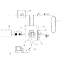
図7は、本実施の形態が適用される竹状窒素含有カーボンナノチューブの製造装置の一例を説明する図である。図7に示す製造装置は、内部に導入された窒素ガスを用いて窒素の超臨界流体を形成するための反応容器12と、反応容器12内に設けられて放電プラズマを生起するための電極15と、電極15に電圧を印加するための外部電源18を備えている。また、外部電源18と電極15の間に設けられた整合器17と、反応容器12の側面に取り付けられて電極15と結合する電極ユニット14と、反応容器12内に供給される窒素ガスを収容する気体シリンダ11と、窒素ガスの流量を調整する調整器13を有している。さらに、プローブ19と分光器20及びパーソナルコンピュータ(PC)21を備えている。反応容器12は、外部から内部を観察できるサファイア製窓16を有している。
<Manufacturing equipment for bamboo-like nitrogen-containing carbon nanotubes>
Next, an apparatus for producing bamboo-like nitrogen-containing carbon nanotubes (N-CNT) will be described.
FIG. 7 is a diagram illustrating an example of an apparatus for producing bamboo-like nitrogen-containing carbon nanotubes to which the present embodiment is applied. The manufacturing apparatus shown in FIG. 7 has a
(超臨界流体)
ここで超臨界流体とは、物質固有の気液の臨界温度を超えた非凝縮性流体と定義される。すなわち、密閉容器内に気体と液体とが存在すると、温度上昇とともに液体は熱膨張しその密度は低下する。一方、気体は、蒸気圧の増加によりその密度が増大する。そして最後に、両者の密度が等しくなり、気体とも液体とも区別の付かない均一な状態になる。物質の温度−圧力線図(図示せず)では、このような状態になる点を臨界点といい、臨界点の温度を臨界温度(Tc)、臨界点の圧力を臨界圧力(Pc)という。また、超臨界流体状態とは、物質の温度及び圧力が臨界点を超えた状態にあることをいう。
(Supercritical fluid)
Here, the supercritical fluid is defined as a non-condensable fluid that exceeds the critical temperature of gas and liquid peculiar to a substance. That is, when a gas and a liquid are present in the closed container, the liquid thermally expands as the temperature rises and its density decreases. On the other hand, the density of gas increases as the vapor pressure increases. Finally, the densities of the two become equal, resulting in a uniform state indistinguishable from gas and liquid. In the temperature-pressure diagram of a substance (not shown), the point at which such a state occurs is called a critical point, the temperature at the critical point is called the critical temperature (Tc), and the pressure at the critical point is called the critical pressure (Pc). The supercritical fluid state means that the temperature and pressure of a substance exceed the critical point.
図7に示す製造装置の反応容器12内において、気体シリンダ11から供給された窒素ガスを用いて窒素の超臨界流体が形成される。反応容器12内に供給される窒素ガスの流量と反応容器12内の圧力は、調整器13により調整され、反応容器12内の放電プラズマ雰囲気圧力が制御される。電極15における放電プラズマの出力は、外部電源18と整合器17により電極15に印加する電圧が調整され、超臨界流体状態における窒素の励起状態を制御している。反応容器12内で生起したプラズマ放電の発光スペクトルは、プローブ19を介して接続された分光器20により測定し、パーソナルコンピュータ(PC)21により解析される。
In the
(反応容器12)
反応容器12は、窒素の超臨界流体を形成することが可能な耐圧性材料を用いて形成されている。本実施の形態では、例えば、ステンレス等が挙げられる。
尚、図示しないが、反応容器12を反応温度に加熱するための加熱装置が設けられている。加熱装置としては、所定の熱媒を使用するジャケット式加熱器、カートリッジ式ヒータ等が挙げられる。また、反応容器12を恒温槽内に設置してもよい。
(Reaction vessel 12)
The
Although not shown, a heating device for heating the
(電極15)
図8は、図7に示す製造装置の反応容器12に使用する電極15を説明する図である。図8に示すように、電極15は、整合器17を介して外部電源18(図7参照)と接続する誘電体バリア放電用電極151と、電極ユニット14(図7参照)を介してアース側に接続する導電性電極152とから構成されている。ここで、誘電体バリア放電とは、一定の間隔をおいた平板の注入側の電極に誘電体を取り付け、これに交流電圧を印加した場合に生起する放電のことである。誘電体バリア放電は、アーク放電に比べ、低電力で放電が可能であり、さらに、放電の持続性が良好である。
(Electrode 15)
FIG. 8 is a diagram illustrating an
本実施の形態では、誘電体バリア放電用電極151は、外部電源18側と接続する第1の金属電極1511(φ15mm)に、アルミナ板1512(20mm×20mm×2.5mm)等の誘電体を挟んで第1の圧粉体1513(φ10mm,L1.0〜1.2mm)等が取り付けられている。
導電性電極152は、アース側に接続する第2の金属電極1521(φ15mm)に、グラファイト平板1522(15mm×15mm×2mm)等の炭素材料を挟んで第2の圧粉体1523(φ10mm,L1.0〜1.2mm)等が取り付けられている。
電極15における誘電体バリア放電用電極151と導電性電極152との電極間距離は、反応容器12内の温度、圧力又は放電条件によって適宜選択され、特に限定されないが、本実施の形態では、0.002mm〜5mmの範囲内で設定される。
In the present embodiment, the dielectric
The
The distance between the dielectric
本実施の形態では、誘電体バリア放電用電極151における第1の圧粉体1513と、導電性電極152における第2の圧粉体1523は、有機遷移金属化合物を所定の成形材を用いて成形することにより得られる。有機遷移金属化合物としては、例えば、鉄(Fe)−フタロシアニン錯体(以下、「Fe−PC」と記載することがある。)、鉄(Fe)−シクロペンタジエニル錯体(フェロセン)等が挙げられる。成形材としては、例えば、アセチレンブラック、バルカン、ケッチェンブラック等が挙げられる。
In the present embodiment, the first green compact 1513 in the dielectric
本実施の形態では、第1の圧粉体1513及び第2の圧粉体1523は、有機遷移金属化合物としてのFe−PCと、成形材としてアセチレンブラックとを、(Fe−PC):アセチレンブラック=64重量%:36重量%、全体量を0.12gとし、乳鉢で10分間混錬した後に、1分間毎に5MPaずつ加圧し、25MPaまで加圧する条件で成形している。 In the present embodiment, the first green compact 1513 and the second green compact 1523 contain Fe-PC as an organic transition metal compound and acetylene black as a molding material (Fe-PC): acetylene black. = 64% by weight: 36% by weight, the total amount is 0.12 g, kneaded in a dairy pot for 10 minutes, then pressurized by 5 MPa every minute, and molded under the condition of pressurizing to 25 MPa.
<竹状窒素含有カーボンナノチューブの製造方法>
次に、上述した製造装置を用いて竹状窒素含有カーボンナノチューブを製造する方法について説明する。
<Manufacturing method of bamboo-like nitrogen-containing carbon nanotubes>
Next, a method for producing bamboo-like nitrogen-containing carbon nanotubes using the above-mentioned production apparatus will be described.
(超臨界流体形成工程)
初めに、気体シリンダ11に貯蔵されている窒素ガス(N2)を反応容器12内に供給する。尚、本実施の形態では、反応容器12内の圧力を調整し、窒素ガス(N2)とアルゴンガス、ヘリウムガス等の希ガスとの混合ガスの超臨界流体において放電プラズマを生起させることもできる。本実施の形態では、窒素ガス(N2)とアルゴンガスとの混合ガスを反応容器12内に供給する。混合ガスの窒素ガス(N2)とアルゴンガスとの組成比は特に限定されないが、本実施の形態では、窒素ガス(N2)/アルゴンガス=(2/8)〜(6/4)(モル比)の範囲で適宜調整される。窒素ガス(N2)とアルゴンガスを併用することにより、超臨界流体における放電プラズマの安定性が向上する傾向がある。
(Supercritical fluid formation process)
First, the nitrogen gas (N 2 ) stored in the
反応容器12内の放電プラズマ雰囲気圧力は適宜調整され、特に限定されないが、本実施の形態では、通常、0.5MPa〜10MPa、好ましくは、5MPa〜5.5MPaの範囲で調整する。尚、本実施の形態では、反応容器12内の圧力を調整し、窒素ガス(N2)とアルゴンガス、ヘリウムガス等の希ガスとの混合ガスの超臨界流体において放電プラズマを生起させることもできる。
The discharge plasma atmospheric pressure in the
本実施の形態では、窒素の超臨界流体は、反応容器12内に供給された窒素ガス(N2)とアルゴンガスとの混合ガスを用いて形成する。窒素の臨界温度(Tc)は126.2K(−147.0℃)、臨界圧力(Pc)は3.39MPaである。また、アルゴンガスの臨界温度(Tc)は150.9K(−122.3℃)、臨界圧力(Pc)は4.86MPaである。
窒素ガス(N2)とアルゴンガスとの混合ガスの場合、混合物の臨界温度(Tc)と臨界圧力(Pc)とは、窒素ガス(N2)とアルゴンガスの組成により、それぞれの物質の臨界温度(Tc)と臨界圧力(Pc)との間で適宜調整することができる。
In the present embodiment, the nitrogen supercritical fluid is formed by using a mixed gas of nitrogen gas (N 2) and argon gas supplied into the reaction vessel 12. The critical temperature (Tc) of nitrogen is 126.2 K (-147.0 ° C), and the critical pressure (Pc) is 3.39 MPa. The critical temperature (Tc) of the argon gas is 150.9K (-122.3 ° C.), and the critical pressure (Pc) is 4.86 MPa.
In the case of a mixed gas of nitrogen gas (N 2 ) and argon gas, the critical temperature (Tc) and critical pressure (Pc) of the mixture are the critical points of each substance depending on the composition of nitrogen gas (N 2 ) and argon gas. The temperature (Tc) and the critical pressure (Pc) can be appropriately adjusted.
(竹状窒素含有カーボンナノチューブ析出工程)
続いて、外部電源18により電極15に電力を印加し、放電プラズマを発生させる。本実施の形態では、外部電源18として高周波電源を用いている。放電プラズマを発生させる放電条件は、電極15間の距離や反応容器12内の圧力により適宜選択され特に限定されない。本実施の形態では、例えば、電源の周波数を13.56MHz、放電出力を40W〜60W程度に設定した場合、放電プラズマを生起する時間は、数秒間〜数時間程度とすることが適当である。
(Bamboo nitrogen-containing carbon nanotube precipitation process)
Subsequently, electric power is applied to the
上述したように、アルゴンガスの存在下で形成された窒素の超臨界流体において、電極15を誘電体バリア放電用電極151と導電性電極152とから構成し、これらに有機遷移金属化合物を含む第1の圧粉体1513と第2の圧粉体1523をそれぞれ取り付け、さらに、電極15に電圧を印加し、誘電体バリア放電を発生させることにより、主として電極15の表面に竹状窒素含有カーボンナノチューブを析出させる。
As described above, in the nitrogen supercritical fluid formed in the presence of argon gas, the
上述した条件で得られる電極15表面の析出物は、TEMの観察により、筒状本体が、竹の形状のように、所定の間隔で複数の節部が形成されている竹状構造体であることが確認されている。また、EDSおよびEELSの測定により、構造中に窒素原子(N)及び炭素原子(C)の存在が確認されている。
The precipitate on the surface of the
11…気体シリンダ、12…反応容器、13…調整器、14…電極ユニット、15…電極、16…サファイア製窓、17…整合器、18…外部電源、19…プローブ、20…分光器、21…パーソナルコンピュータ(PC)、151…誘電体バリア放電用電極、152…導電性電極、1511…第1の金属電極、1512…アルミナ板、1513…第1の圧粉体、1521…第2の金属電極、1522…グラファイト平板、1523…第2の圧粉体 11 ... Gas cylinder, 12 ... Reaction vessel, 13 ... Regulator, 14 ... Electrode unit, 15 ... Electrode, 16 ... Sapphire window, 17 ... Matcher, 18 ... External power supply, 19 ... Probe, 20 ... Spectrometer, 21 ... Personal computer (PC), 151 ... Dielectric barrier discharge electrode, 152 ... Conductive electrode, 1511 ... First metal electrode, 1512 ... Alumina plate, 1513 ... First powder, 1521 ... Second metal Electrode, 1522 ... Graphite flat plate, 1523 ... Second green compact
Claims (7)
内部に導入された窒素ガスの超臨界流体を形成する反応容器と、
前記反応容器の内部に設けられた電極と、
前記電極に電圧を印加し当該電極間に放電を生起させる外部電源と、を備え、
前記電極は、第1と第2の両金属電極部に、グラファイト平板と有機金属化合物を含む圧粉体を取り付けた構成であることを特徴とする竹状窒素含有カーボンナノチューブの製造装置。Bamboo nitrogen-containing carbon nanotube manufacturing equipment
A reaction vessel that forms a supercritical fluid of nitrogen gas introduced inside,
The electrodes provided inside the reaction vessel and
An external power source that applies a voltage to the electrodes to generate a discharge between the electrodes is provided.
The electrode is an apparatus for producing bamboo-like nitrogen-containing carbon nanotubes, which comprises a structure in which a graphite flat plate and a green compact containing an organometallic compound are attached to both first and second metal electrode portions.
有機遷移金属化合物を含む圧粉体の電極を備える反応容器の内部に窒素の超臨界流体を形成する超臨界流体形成工程と、
前記超臨界流体が形成された状態において、前記有機遷移金属化合物を含む圧粉体の電極に電圧を印加して当該電極間に放電プラズマを生起させ、当該電極の表面に竹状窒素含有カーボンナノチューブを析出させる竹状窒素含有カーボンナノチューブ析出工程と、
を有することを特徴とする竹状窒素含有カーボンナノチューブの製造方法。A method for producing bamboo-like nitrogen-containing carbon nanotubes.
A supercritical fluid forming step of forming a supercritical fluid of nitrogen inside a reaction vessel provided with an electrode of a green compact containing an organic transition metal compound,
In the state where the supercritical fluid is formed, a voltage is applied to the electrodes of the green compact containing the organic transition metal compound to generate discharge plasma between the electrodes, and bamboo-like nitrogen-containing carbon nanotubes are generated on the surface of the electrodes. Bamboo nitrogen-containing carbon nanotube precipitation step and
A method for producing bamboo-like nitrogen-containing carbon nanotubes.
Priority Applications (1)
| Application Number | Priority Date | Filing Date | Title |
|---|---|---|---|
| JP2016018339A JP6876216B2 (en) | 2016-02-02 | 2016-02-02 | Bamboo nitrogen-containing carbon nanotubes, bamboo nitrogen-containing carbon nanotube manufacturing equipment, and bamboo nitrogen-containing carbon nanotube manufacturing methods |
Applications Claiming Priority (1)
| Application Number | Priority Date | Filing Date | Title |
|---|---|---|---|
| JP2016018339A JP6876216B2 (en) | 2016-02-02 | 2016-02-02 | Bamboo nitrogen-containing carbon nanotubes, bamboo nitrogen-containing carbon nanotube manufacturing equipment, and bamboo nitrogen-containing carbon nanotube manufacturing methods |
Publications (2)
| Publication Number | Publication Date |
|---|---|
| JP2017137206A JP2017137206A (en) | 2017-08-10 |
| JP6876216B2 true JP6876216B2 (en) | 2021-05-26 |
Family
ID=59565543
Family Applications (1)
| Application Number | Title | Priority Date | Filing Date |
|---|---|---|---|
| JP2016018339A Expired - Fee Related JP6876216B2 (en) | 2016-02-02 | 2016-02-02 | Bamboo nitrogen-containing carbon nanotubes, bamboo nitrogen-containing carbon nanotube manufacturing equipment, and bamboo nitrogen-containing carbon nanotube manufacturing methods |
Country Status (1)
| Country | Link |
|---|---|
| JP (1) | JP6876216B2 (en) |
Families Citing this family (1)
| Publication number | Priority date | Publication date | Assignee | Title |
|---|---|---|---|---|
| CN118954614B (en) * | 2024-10-16 | 2025-02-11 | 浙江华宇钠电新能源科技有限公司 | Preparation method of ferrous sodium sulfate positive electrode material for sodium ion battery and vehicle |
Family Cites Families (5)
| Publication number | Priority date | Publication date | Assignee | Title |
|---|---|---|---|---|
| JP3837573B2 (en) * | 2004-03-19 | 2006-10-25 | 独立行政法人物質・材料研究機構 | Method for producing carbon nanotube bonded with nitrogen atom |
| JP2006103996A (en) * | 2004-10-01 | 2006-04-20 | National Institute For Materials Science | Carbon nanotubes containing nitrogen atoms and method for producing the same |
| JP4887483B2 (en) * | 2005-03-04 | 2012-02-29 | 国立大学法人東京農工大学 | Carbon material and manufacturing method thereof |
| JP5003923B2 (en) * | 2008-03-06 | 2012-08-22 | 宇部興産株式会社 | Fine carbon fiber, fine short carbon fiber and method for producing them |
| JP2011230993A (en) * | 2010-04-30 | 2011-11-17 | Kumamoto Univ | Method of manufacturing carbon material |
-
2016
- 2016-02-02 JP JP2016018339A patent/JP6876216B2/en not_active Expired - Fee Related
Also Published As
| Publication number | Publication date |
|---|---|
| JP2017137206A (en) | 2017-08-10 |
Similar Documents
| Publication | Publication Date | Title |
|---|---|---|
| Kramberger et al. | Assignment of chiral vectors in carbon nanotubes | |
| Venkateswaran et al. | Probing the single-wall carbon nanotube bundle: Raman scattering under high pressure | |
| Hirata et al. | Magnetron-type radio-frequency plasma control yielding vertically well-aligned carbon nanotube growth | |
| US9418814B2 (en) | Planar field emitters and high efficiency photocathodes based on ultrananocrystalline diamond | |
| Xue et al. | Microwave-frequency effects on microplasma | |
| JP6876216B2 (en) | Bamboo nitrogen-containing carbon nanotubes, bamboo nitrogen-containing carbon nanotube manufacturing equipment, and bamboo nitrogen-containing carbon nanotube manufacturing methods | |
| Lim et al. | Enhanced field emission properties of carbon nanotube bundles confined in SiO2 pits | |
| Inoue et al. | Chirality analysis of horizontally aligned single-walled carbon nanotubes: decoupling populations and lengths | |
| Ting et al. | Optimization of field emission properties of carbon nanotubes by Taguchi method | |
| Kar et al. | Synthesis mechanism and ‘orthodoxy’test based field emission analysis of hybrid and pristine graphene nanowalls deposited on thin Kovar wires | |
| Nagaya et al. | Producing multicharged fullerene ion beam extracted from the second stage of tandem-type ECRIS | |
| Adessi et al. | Field-enhancement properties of nanotubes in a field emission setup | |
| KR20160118835A (en) | Apparatus and method of fabricating boron nitride nanotube | |
| Shivkumar et al. | Discharge regimes and emission characteristics of capacitively coupled radio frequency argon plasma with a square wave input | |
| Sominskii et al. | Perspective field emitters for electron-beam microwave devices of short-wave millimeter and submillimeter range | |
| Roy et al. | Low temperature growth of carbon nanotubes with aligned multiwalls by microwave plasma-CVD | |
| Nikolski et al. | Field emission investigation of carbon nanotubes doped by different metals | |
| JP2005032542A (en) | Electron reflection suppressing material and its manufacturing method | |
| Bezmel’nitsyn et al. | Preparation of single-walled nanotubes with the help of a Ni/Cr-based catalyst | |
| Ding et al. | Combined study of the ground and excited states of carbon onions by electron energy-loss spectroscopy: Comparison with highly ordered pyrolytic graphite | |
| Katoh et al. | Electronic properties of CrF and CrCl in the X 6 Σ+ state: Observation of the halogen hyperfine structure by Fourier transform microwave spectroscopy | |
| JP2021109787A (en) | Carbon film and its film forming method | |
| JP4456442B2 (en) | Method for producing carbon nitride | |
| Qin et al. | Study on preparation and electron emission characteristics of vapor phase growth cylindrical CNTs cathodes for magnetron application | |
| Ali et al. | Innovative multiwall carbon nanotubes synthesis on 3D nickel surface: a comparative study |
Legal Events
| Date | Code | Title | Description |
|---|---|---|---|
| A521 | Request for written amendment filed |
Free format text: JAPANESE INTERMEDIATE CODE: A523 Effective date: 20160225 |
|
| A521 | Request for written amendment filed |
Free format text: JAPANESE INTERMEDIATE CODE: A523 Effective date: 20160307 |
|
| A621 | Written request for application examination |
Free format text: JAPANESE INTERMEDIATE CODE: A621 Effective date: 20190201 |
|
| A521 | Request for written amendment filed |
Free format text: JAPANESE INTERMEDIATE CODE: A821 Effective date: 20190201 |
|
| A521 | Request for written amendment filed |
Free format text: JAPANESE INTERMEDIATE CODE: A523 Effective date: 20190531 |
|
| RD04 | Notification of resignation of power of attorney |
Free format text: JAPANESE INTERMEDIATE CODE: A7424 Effective date: 20190731 |
|
| A977 | Report on retrieval |
Free format text: JAPANESE INTERMEDIATE CODE: A971007 Effective date: 20190925 |
|
| A131 | Notification of reasons for refusal |
Free format text: JAPANESE INTERMEDIATE CODE: A131 Effective date: 20191015 |
|
| A601 | Written request for extension of time |
Free format text: JAPANESE INTERMEDIATE CODE: A601 Effective date: 20191114 |
|
| A521 | Request for written amendment filed |
Free format text: JAPANESE INTERMEDIATE CODE: A523 Effective date: 20200129 |
|
| A521 | Request for written amendment filed |
Free format text: JAPANESE INTERMEDIATE CODE: A523 Effective date: 20200430 |
|
| A131 | Notification of reasons for refusal |
Free format text: JAPANESE INTERMEDIATE CODE: A131 Effective date: 20200811 |
|
| A601 | Written request for extension of time |
Free format text: JAPANESE INTERMEDIATE CODE: A601 Effective date: 20201007 |
|
| A521 | Request for written amendment filed |
Free format text: JAPANESE INTERMEDIATE CODE: A523 Effective date: 20201012 |
|
| TRDD | Decision of grant or rejection written | ||
| A01 | Written decision to grant a patent or to grant a registration (utility model) |
Free format text: JAPANESE INTERMEDIATE CODE: A01 Effective date: 20210302 |
|
| A61 | First payment of annual fees (during grant procedure) |
Free format text: JAPANESE INTERMEDIATE CODE: A61 Effective date: 20210316 |
|
| R150 | Certificate of patent or registration of utility model |
Ref document number: 6876216 Country of ref document: JP Free format text: JAPANESE INTERMEDIATE CODE Ref document number: 6876216 Country of ref document: JP Free format text: JAPANESE INTERMEDIATE CODE: R150 |
|
| LAPS | Cancellation because of no payment of annual fees |