JP6875384B2 - Equipment and methods for sampling gaseous fluids - Google Patents
Equipment and methods for sampling gaseous fluids Download PDFInfo
- Publication number
- JP6875384B2 JP6875384B2 JP2018516440A JP2018516440A JP6875384B2 JP 6875384 B2 JP6875384 B2 JP 6875384B2 JP 2018516440 A JP2018516440 A JP 2018516440A JP 2018516440 A JP2018516440 A JP 2018516440A JP 6875384 B2 JP6875384 B2 JP 6875384B2
- Authority
- JP
- Japan
- Prior art keywords
- flow
- inlet
- detector
- plenum
- fluid
- Prior art date
- Legal status (The legal status is an assumption and is not a legal conclusion. Google has not performed a legal analysis and makes no representation as to the accuracy of the status listed.)
- Active
Links
Images


Classifications
-
- G—PHYSICS
- G01—MEASURING; TESTING
- G01N—INVESTIGATING OR ANALYSING MATERIALS BY DETERMINING THEIR CHEMICAL OR PHYSICAL PROPERTIES
- G01N1/00—Sampling; Preparing specimens for investigation
- G01N1/02—Devices for withdrawing samples
- G01N1/22—Devices for withdrawing samples in the gaseous state
- G01N1/2202—Devices for withdrawing samples in the gaseous state involving separation of sample components during sampling
- G01N1/2211—Devices for withdrawing samples in the gaseous state involving separation of sample components during sampling with cyclones
-
- G—PHYSICS
- G01—MEASURING; TESTING
- G01N—INVESTIGATING OR ANALYSING MATERIALS BY DETERMINING THEIR CHEMICAL OR PHYSICAL PROPERTIES
- G01N1/00—Sampling; Preparing specimens for investigation
- G01N1/02—Devices for withdrawing samples
- G01N1/22—Devices for withdrawing samples in the gaseous state
Description
本発明は検出方法及び装置に関し、またより具体的には、検出器用のサンプルを採取するための方法及び装置に関し、さらにより具体的には、粒子が存在する蒸気のサンプルを採取する方法及び装置に関し、これら方法及び装置は、分光分析、例えばイオン移動度分光分析(Ion mobility spectrometry)及び質量分光分析(mass spectrometry)に特別な用途を見出すことができる。 The present invention relates to a detection method and an apparatus, more specifically, a method and an apparatus for collecting a sample for a detector, and more specifically, a method and an apparatus for collecting a sample of steam in which particles are present. With respect to, these methods and devices can find special applications in spectroscopic analysis, such as ion mobility spectroscopy and mass spectrometry.
幾つかの検出器は、分析装置で空気のような流体の流れを検出器入口内に「吸入」し、その空気をサンプリングし、関心対象物質を検出することによって動作する。その吸入空気の流れは、ピンホール、毛細管又は薄膜入口のようなサンプリング入口を用いて検出器入口からサンプリングすることができる。 Some detectors operate by "inhaling" a flow of fluid, such as air, into the detector inlet with an analyzer, sampling the air, and detecting the substance of interest. The intake air flow can be sampled from the detector inlet using a sampling inlet such as a pinhole, capillary or thin film inlet.
携帯型又は可搬式デバイスが、例えば、軍事及びセキュリティ要員の使用のためにしばしば必要となり得る。これら要員は、多量の砂塵及び他の粒子物質が存在する厳しい環境内で活動することがよくある。このような粒子は、サンプリング入口を閉塞させるか、そうでない場合、検出器にダメージを与えかねない。幾つかのケースにおいて、空気の流れに搬送される粒子には、検出器が敏感性を示す物質を含む場合があり得る。これら粒子が検出器又は入口内に溜まる場合、検出器を汚染し、また復旧時間問題を引き起こしかねない。 Portable or portable devices may often be needed, for example, for the use of military and security personnel. These personnel often operate in harsh environments with large amounts of dust and other particulate matter. Such particles can block the sampling inlet or otherwise damage the detector. In some cases, the particles carried in the air stream may contain substances that the detector is sensitive to. If these particles collect in the detector or inlet, they can contaminate the detector and cause recovery time problems.
本発明の態様及び実施形態は、関連する技術的問題に対処することを目的とする。 Aspects and embodiments of the present invention are intended to address related technical issues.
本発明の実施形態を以下に例としてのみ添付図面につき説明する。 Embodiments of the present invention will be described below with reference to the accompanying drawings only as an example.
図面において、同様の参照符号は同様の素子を示すのに使用する。 In the drawings, similar reference numerals are used to indicate similar elements.
本発明の実施形態は、関心対象サンプルを検出する分析装置にサンプルを供給する検出器入口に関する。このような検出器は、先ず粒子を搬送する空気、蒸気及びエアロゾルのようなガス状流体のフローを吸入することによってサンプルを採取することができる。次に、このフローからサンプルを取り込むことができる。例えば、ピンホール入口を用いて、これらサンプルを取り込み、また関心対象物質を検出することができる検出器に供給し得る。 An embodiment of the present invention relates to a detector inlet that supplies a sample to an analyzer that detects a sample of interest. Such a detector can first take a sample by inhaling a flow of gaseous fluids such as air, vapor and aerosol carrying the particles. You can then take a sample from this flow. For example, a pinhole inlet can be used to capture these samples and feed them to a detector capable of detecting the substance of interest.
このような吸入フロー内に同伴される粒子は、吸入フロー全体にわたり空間的に均一に分布し得る。このような粒子の存在は、検出器汚染又はサンプリング入口の閉塞をもたらしかねない。本発明の実施形態は、蒸気のサンプリングを可能にするとともに、粒子がサンプリング入口に進入する又は詰まらせるのを抑止することを目的とする。このことは、サンプルを採取する(例えば、検出器のサンプリング入口によって)ことができる領域を取り囲む(包囲する)循環フローを誘導することによって達成することができる。この領域において粒子の相対数が激減し、これはすなわち、そうでない場合に相当均一な空間的分布となるものがこの循環フローの遠心効果によって変更されるからである。 The particles entrained in such a suction flow can be spatially uniformly distributed throughout the suction flow. The presence of such particles can result in detector contamination or blockage of the sampling inlet. It is an object of the present invention to enable sampling of steam and to prevent particles from entering or clogging the sampling inlet. This can be achieved by inducing a circulating flow that surrounds (surrounds) the area where the sample can be taken (eg, by the sampling inlet of the detector). The relative number of particles is depleted in this region, that is, what would otherwise be a fairly uniform spatial distribution is altered by the centrifugal effect of this circulating flow.
本発明の明細書は、このことを達成する多数のやり方を説明する。図1aはこのように動作するよう構成される検出器入口を示す。 The specification of the present invention describes a number of ways to achieve this. FIG. 1a shows a detector inlet configured to operate in this way.
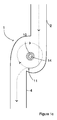
図1aは、フロー入口2、フロー出口4及びプレナム11を備える検出器入口1を示す。プレナム11は、内面12を有する壁8からなる。プレナムにおけるサンプリング容積部10からサンプルを採取するピンホールのようなサンプリング入口14を配置する。図2は図1aの検出器入口の断面図を示す。図2からは、サンプリング入口をプレナム11の中心領域からガス状流体のサンプルを収集するよう構成できることが分かる。例えば、図1において、プレナムは、吸入したフローの経路が図面の平面に整列する平面図で示される。この図において、プレナム11は、丸みがある形状、例えば円形の形状を有する。サンプリング入口は、この丸みがある形状のプレナムの中央に又はその近傍に配置することができる。
FIG. 1a shows a
フロー入口2及びフロー出口4は、それぞれ材料ブロックを切削しかつ材料で囲まれるチャンネル、又はパイプ若しくはチューブのような導管から構成することができる。図1に示すフロー入口及びフロー出口は異なる方向に整列する。フロー入口2及びフロー出口4は双方ともにプレナム11に接合し、したがって、検出器入口1を通過する流体の経路における湾曲部に存在する。プレナム11において、ガス状流体のフローは、ガス状流体がフロー入口2からプレナム11を経てフロー出口4に流れるとき方向転換を受ける。
The
プレナム11は、壁8の内面12によって区切られる内側容積部を有する。図示のように、壁8の内面12は湾曲し、例えば、壁8の内面12の曲率は、フロー入口2からフロー出口4への吸入フローの経路に湾曲部を生ずるよう構成することができる。図2に示すように、プレナムのフロー断面はフロー入口2のフロー断面よりも大きい。この状況において、フロー断面は、ガス状流体のフロー方向に交差する方向の面積を意味する。例えば、プレナム11は、フロー入口2がプレナム11に合流するフロー経路の拡開を生ずることができる。このことは、ガス状流体がプレナム11に進入するときにガス状流体のフローを遅くするよう作用し得る。図2の図示において、フロー出口4は、フロー出口4よりも大きいフロー断面を有する平面で示す。このことは、フロー出口4においてプレナムから流出するガス状流体により遅いフロー速度を付与する1つの方法である。出口でフロー速度をより遅くすることは、プレナムを巡る循環フローの生成を促すことができる。
The
上述したように、フロー入口2は、ガス状流体をプレナム11に導き入れるよう構成する。プレナム11は、プレナム11によってサンプリング入口の一方の側を通り越して設けられる湾曲部の外側周りの第1フロー経路と、及びサンプル入口の他方の側を通り越して設けられる湾曲部の内側周りの第2フロー経路とを有する。このようにして、プレナム11の中央に又はその近傍にサンプリング入口を位置決めすることによって、サンプリング入口14を取り囲む流体の循環フローを誘発することができる。この循環フローは、流体が搬送する粒子の空間的分布を変化させて、サンプリング入口14がサンプルを採取するサンプリング容積部10に進入することなくサンプリング入口14を通り越して搬送される粒子の相対的比率を増加させることができる。フロー出口4は、ガス状流体がフロー入口2から流入するよりも遅い速度でガス状流体のフローがプレナム11から流出するよう構成することができる。例えば、フロー出口4は、より広いフロー断面にして、フロー出口14を経由するガス状流体の体積流量率がフロー入口2を経由するのと同一体積流量率と同一であるが、より遅い線速度で流れることができるようにする。このことは、ガス状流体が湾曲部の内側でサンプリング入口を通り越して戻るよう流れる傾向を増長することができる。例えば、流体がプレナム11内に流入することができるこのような実施形態において、フローは流入後にサンプリング入口における一方の側の周りに湾曲し、フロー出口4における遅く流れる流体によってフロー出口4に全面的に進入するのを阻止され、また少なくとも部分的にサンプリング入口14の他方の側でサンプリング入口を通り越して戻るよう流れることによってプレナムを循環する。
As described above, the
図1aの装置の動作において、ガス状流体のフローは、吸入されてフロー入口2からプレナム11を経てフロー出口4に移動する。プレナム11は吸入されたガス状流体におけるこのフローの方向を変化させる、例えば、フロー入口2からのフロー方向を曲げる。この曲げの外側は、内方に湾曲するプレナムの壁8によって生ずる。このことは吸入された流体のフロー方向を変化させ、また流体がプレナム11を経て流れるとき流体フローをサンプリング入口の周りに曲げる。流体がフロー出口4に達するとき、幾らかのガス状流体は出口4を経てプレナム11から退出するが、幾らかのガス状流体は、フロー出口4を通り越して流れにおける渦流のように湾曲部13の内側13でサンプリング入口の他方の側を通り越して戻る方向に案内され、プレナム11に留まる。サンプリング入口を通り越して戻る方向に流れて再びフロー入口2に復帰したとき、この逆流フローは、フロー入口でプレナム11に到達する他のフローに再合流することができる。これと同一のサイクルが再開して、この再合流フローのうち幾分かが再循環するとともに、幾分かは出口4から退出する。したがって、ガス状流体フローのうち少なくとも一部に関して、このような実施形態は、一定断面の真直ぐなパイプに沿う同一フローと比較すると、サンプリング入口周りにおけるガス状流体の滞留(ドウェル)時間を増大させることができる。
In the operation of the apparatus of FIG. 1a, the flow of the gaseous fluid is sucked in and moves from the
したがって、流体の少なくとも一部分は、プレナム内周りでサンプリング入口を包囲する湾曲した、例えば少なくとも部分的に円形のフロー経路を流れてからフロー出口4からプレナムを抜け出ることができる。この循環フローは、入口2及び出口4を通過するガス状流体のバルクフロー方向に交差する、例えば直交する回転軸線の周りに循環することが図2から分かる。
Thus, at least a portion of the fluid can flow through a curved, eg, partially circular, flow path that surrounds the sampling inlet around the inside of the plenum before exiting the plenum through the
この循環フローは、サンプリング入口周りの遠心効果をもたらすことができ、この遠心効果は、フローが搬送する粒子をプレナムの壁に向けて、例えば、サンプリング入口から遠ざかる移動をさせようとする。このことは、循環フローの回転軸線に向かう領域であって、ガス状流体における粒子比率がガス状流体フロー他の領域、例えば、プレナム11の壁により近接する流体フロー領域に比べて低減される領域を生ずる。しかし、フローによって搬送される蒸気は、プレナム11周りに自由に拡散し、この低減領域内に留まる。したがって、本発明方法は、この低減領域からガス状流体のサンプルを収集して、サンプリング入口を詰まらせる又はこのサンプリング入口に進入して検出器を汚染することがあり得る粒子の数を減らすステップを備える。
This circulating flow can provide a centrifugal effect around the sampling inlet, which attempts to move the particles carried by the flow towards the walls of the plenum, eg, away from the sampling inlet. This is a region toward the rotation axis of the circulating flow, in which the particle ratio in the gaseous fluid is reduced compared to other regions of the gaseous fluid flow, eg, a fluid flow region closer to the wall of the
ラインA及びサンプリング容積部10に沿う粒子の分布を図1bにおけるプロットグラフで示す。図1bに示すように、粒子の数(例えば、単位容積当たりの数)は壁の表面からの距離の関数として減少する。例えば、粒子の数は、サンプリング容積部10に向かうにつれて、また湾曲部の内側13から離れるにつれて低下する。上述したように、遠心効果が粒子をプレナムの壁に向う方向に移動させ、またこの運動はサンプリング容積部に向かう壁からの距離とともに粒子の数を変化させる。図1bに示す粒子分布は、壁の表面12とサンプリング容積部10との間における領域に比べて湾曲部の内側13とサンプリング容積部10との間における領域の方が粒子の数がより少ないことを示す。粒子理論に固執したくはないが、壁の表面12とサンプリング容積部10との間における流体の一部が湾曲部の内側13とサンプリング容積部10との間における領域に通過し、したがって、湾曲部の内側13とサンプリング容積部10との間における流体はより大きい遠心効果を受けており、またひいては、より少ない粒子を含むことになり得る。しかし、このような分布は単なる例であることを理解されたい。
The distribution of particles along the line A and the
壁の曲率は、粒子が検出器入口1の内面に衝突するのを減らすよう選択することができる。例えば、壁の曲率半径は、流体フローに対して滑らかな経路を付与するよう壁の異なる部分で相違させることができる。例えば、壁のフロー入口2に隣接する第1部分及び壁のフロー出口4に隣接する第2部分の双方は、壁における第1部分を第2部分に接合する部分よりも大きい曲率半径にする。この曲率半径変化は、吸入ガス状流体のフロー方向に緩やかな変化をもたらす。このことは、ガス状流体によって搬送される粒子及びエアロゾルがプレナムの壁に衝突しまた堆積する傾向を減少することができる。
The curvature of the wall can be selected to reduce particles from colliding with the inner surface of the
図1cは、図1aにつき上述したような検出器入口の実施例を示す。しかし、この図1cにおいては、フロー入口2はフロー出口4と同一向きに整列する。フロー出口4は、しかし、フロー入口2からはオフセットしている。図1cに示す実施例に関しては、フロー出口4は、フロー入口2から側方に、例えば、流体フローの方向に交差する方向に離間する。この実施例において、流体の少なくとも一部分はサンプリング入口を取り囲むプレナム周りの円として流動してから、フロー入口2に平行な方向にフロー出口4を経由してプレナムから退出することができる。図1cに示す実施例において、フロー出口4は、プレナムのフロー入口2とは反対側8に配置する。したがって、ガス状流体は、フロー入口2からプレナムに流入するのと同一方向にフロー出口4を経由してプレナムから流出することができる。しかし、他の実施形態において、フロー出口4はプレナム8のフロー入口2と同一側に配置することもできる。例えば、プレナムはU字屈曲の曲げ部に配置することができる。これら及び他の実施例は、ガス状流体フローの方向に交差する軸線周りに回転する循環フローを生ずる。
FIG. 1c shows an example of a detector inlet as described above for FIG. 1a. However, in FIG. 1c, the
検出器入口の他の構成も設けることができる。プレナム内における流体の循環フローはフロー方向に整列する軸線周りに循環することもできる。例えば、プレナムは、流体がシリンダに沿って流動できるよう構成した該シリンダのような導管又はフロー通路32を有することができる。このような構成において、循環フローの回転軸線は、フロー通路の長手方向軸線に整列し得る。このような1つの実施例を図3aに示す。
Other configurations of the detector inlet can also be provided. The fluid circulation flow in the plenum can also circulate around an axis aligned in the flow direction. For example, the plenum can have a cylinder-like conduit or flow
図3aに示す実施例において、検出器入口は、ガス状流体のフロー方向に平行な軸線周りに回転する循環フローを生ずるよう構成したフロー通路32を備える。上述したように、循環フローは、フロー内粒子の空間的分布に変化をもたらし、フロー通路の壁に近づくにつれて比較的より多くの粒子がフローに搬送される。粒子数はフロー通路の壁からの距離の関数としても減少する。
In the embodiment shown in FIG. 3a, the detector inlet is provided with a
より詳細には、図3aは、フロー通路32、フロー入口29、第1フロー出口28、及び第2フロー出口30を備える検出器入口を示す。フロー通路32は、壁33と、フロー通路32の壁33の内面に配列したフィン22の形式であるフロー導向器と、サンプリング容積部24と、及びサンプリング入口14とを有する。図4は、図3aのマークBを付けたラインにおけるフロー通路32の断面を示す。
More specifically, FIG. 3a shows a detector inlet comprising a
図3a及び図4に示す実施例において、フロー通路32は、材料ブロックを切削しまた材料で囲まれるチャンネル、又はパイプ若しくはチューブのような導管から構成する。フロー通路32はバルクフロー方向を画定する。フロー入口29はこのフロー通路32の一部を構成する。第1フロー出口28及び第2フロー出口30は、フロー通路32に沿ってフロー入口29から離間し、通路の管体軸線から遠ざかる方向に延在する。例えば、フロー出口28、30はフロー通路32から分岐することができる。例えば、フロー通路32に対して角度をなすよう配置することができる。これらフロー出口はフロー通路32に対して交差する(例えば、直交する)よう配列するが、幾つかの実施形態において、フロー通路32の方向に少なくとも部分的に整列することができる。例えば、フロー通路及びフロー出口28,30は、Y字状に配列することができる。図3aに示す実施例において、第1フロー出口28及び第2フロー出口30は管体から異なる方向に延在することができ、例えば、第1フロー出口28は、第2フロー出口30によって搬送される流体フローとは反対方向にガス状流体フローを搬送するよう配列することができる。
In the embodiment shown in FIGS. 3a and 4, the
図3aにおいて、フロー導向器は、フロー通路32の内壁33から突出するフィン22を有する。フィン22は、フロー通路32の周りにまたフロー通路に沿うねじのねじ山のような螺旋状経路に整列することができる。フロー導向器として作用するため、このフィン(又はこれらフィン)は、フロー通路を流動する流体の少なくとも一部分の経路に存在する。図示の実施例において、フロー導向器はフロー通路32の壁に結合した2つのフィン22の形式とする。単独のフィン又はそれより多い数のフィンを使用することもできる。フィン22は、フロー通路に沿う螺旋状(例えば、コルク栓抜き状)経路の少なくとも一部分に整列する薄く細長い構体を有する限り、連続的である必要はない。このフィン(又はこれらフィン)は、螺旋軸線がフロー通路32に整列する螺旋状経路に沿ってフロー通路の内壁によって担持することができ、例えば、螺旋状経路はフロー通路32と同軸状にすることができる。フィン22は、フロー通路32の壁33に固着することができ、例えば、フロー通路32にはフィン22を一体に形成することができる。フィンはフロー通路32の壁33から少なくとも10ミクロン突出することができる。
In FIG. 3a, the flow director has
フロー通路32はフロー入口29からサンプルを受け入れるよう構成する。フロー通路32の壁内面におけるフィン22は、流体のフロー方向を変化させ、フロー通路32のバルクフロー方向に整列する回転軸線を有する循環フロー20で流体が流動するよう構成する。サンプリング入口14はサンプリング容積部24からサンプルを採取するよう配列し、例えば、図3aに示すように、サンプリング入口は、サンプリング容積部の中心に配置することができる。図4は図3aのフロー通路32の断面図を示す。図4は、フロー通路32に同軸状であり、また流体フロー20によって取り囲まれるサンプリング容積部を示す。フロー経路20は、図3a及び図4において、壁33の内面を流動しかつフィン22によって反時計方向に導かれる流体の循環フローにより示す。
The
動作にあたり、ガス状流体はフロー入口29から吸入され、フロー通路32を経由して第1フロー出口28及び第2フロー出口30から流出する。フロー通路32の内壁33から突出するフロー導向器は、フロー通路におけるガス状流体フローの方向を変化させる。流体がフロー通路に沿って移動するとき、方向変化が流体に回転を付与し、これにより例えば、銃身に沿って移動する銃弾に回転運動を誘導する銃身旋条痕のように、流体フローはフロー通路の軸線を取り囲む。ガス状流体は、フロー通路の軸線周りに回転し続けるとともに、第1フロー出口28及び第2フロー出口30に向かって移動する。この後、ガス状流体は第1フロー出口28及び第2フロー出口30を経由してフロー通路から退出する。
In operation, the gaseous fluid is sucked from the
図3a及び図4に示す循環流体フロー経路20はフロー通路に沿うフロー方向に対応する軸線を有する螺旋状フロー経路である。このフロー経路は、フィン22の配列によって付与することができる。図3a及び図4に示す構成において、フィン22は、フロー通路の表面に配列され、フロー通路の軸線に同軸状の軸線を有する螺旋パターンを形成するよう指向性を与えられる。したがって、流体は、フィン22の指向性に追随してフロー通路32に沿う螺旋状経路で導向される。図3a及び図4に示す実施例において、フィンは、流体フローに対して反時計方向の螺旋をなすよう配列され、したがって、流体がフロー通路に沿って流動するとき、流体フィンは流体を反時計方向に回転させる。
The circulating
フロー通路における流体の循環フローは、流体が搬送する粒子の空間的分布を変化させることができる。上述したように、循環フローは、粒子をフロー通路の壁33に向けて移動させる循環フローの遠心効果により、サンプリング容積部24に進入することなくサンプリング入口14を通り越して搬送される粒子の相対的比率を増加させることができる。壁に向かう粒子の運動は、サンプリング容積部における粒子比率をより低下させ、したがって、サンプリング容積部における蒸気の比率を増加させる。
The circulation flow of the fluid in the flow passage can change the spatial distribution of the particles carried by the fluid. As described above, the circulation flow is the relative of the particles transported past the
図3aに示す実施例において、流体循環フローの性質はフィン22の配列によって決定される。例えば、フロー通路32の所定長さあたりフロー通路32の軸線周りを流体が回転する回数は、フロー通路32の壁33におけるフィン22の位置によって決定される。フロー通路32の長さに沿うより多くの回転数を有するフィン配列、例えば、より小さいピッチの螺旋となるよう配列されるフィンによれば、ガス状流体がフロー通路の長さに沿って移動するとき、フロー通路の軸線周りにより多くの回転サイクルを流体にもたらすことができる。
In the embodiment shown in FIG. 3a, the nature of the fluid circulation flow is determined by the arrangement of the
ラインB及びサンプリング容積部24に沿う粒子の分布を図3bにおけるプロットグラフで示す。図3bに示すように、粒子の数はフロー通路の壁33からサンプリング入口に至るまで減少する。上述したように、遠心効果が粒子をプレナムの壁に向って移動させ、またこのことがフロー通路32の軸線付近に位置するサンプリング容積部24における粒子の数を減少させる。
The distribution of particles along the line B and the
サンプリング入口14は検出器入口1に接続し、またサンプリング入口14周りのサンプリング容積部10,24から流体のサンプルを収集し得るようにする。本明細書に記載の実施形態において、ガス状流体のフローからサンプルを取り込むのに使用されるサンプリング入口は、ピンホール入口を有することができる。サンプラー(図示せず)は、サンプリング容積部10,24よりも少量の選択された流体量をサンプリング入口14から吸引して分析装置にサンプルを供給するよう構成する。サンプラーは、蒸気をサンプリング容積部10、24からサンプリング入口14を経由して分析装置に送給するよう構成された電気機械的アクチュエータ、例えばソレノイド駆動アクチュエータ及び/又は機械的ポンプを備えることができる。
The
図5はサンプリング入口14を介して検出器入口1に接続した検出器48を示し、また図6はサンプリング入口14を介して検出器入口3に接続した検出器48を示す。検出器48は、サンプリング入口を介して流体のサンプルを採取するよう構成したサンプラー52と、及び分析装置53とを有する。
FIG. 5 shows the
分析装置53は、サンプリング入口から受け入れたサンプルを分析する、例えば、サンプルにおける関心対象の1つ又はそれ以上の化学物質を決定するよう構成する。図5及び図6に示す分析装置53は質量分析装置を有する。質量分析装置は、イオン化装置と、イオン加速器と、ビーム合焦器と、磁石と、及び蒸気のサンプルに対して質量分光分析を行うよう構成されたファラデー捕集器とを有することができる。
The
図示のように、コントローラ50を接続して、分析装置、フロー供給器及びサンプラー52を制御する。コントローラ50は、プロセッサ、及び検出器48を動作させる命令を記憶するメモリを有することができる。
As shown, a
図7及び図8は、分析装置がイオン移動度分光分析装置72を有する検出器68を示すが、それ以外は図5及び図6に示す装置と同一である。図7のイオン移動度分光分析装置はサンプリング入口14によって検出器入口1に接続する。サンプラー52は、サンプリング入口14から流体のサンプルを採取し、またイオン移動度分光分析装置72に供給するよう構成される。図5及び図6の実施例と同様に、コントローラ50は、プロセッサ、及び検出器68を動作させる命令を記憶するメモリを有することができる。さらに、図5及び図6の実施例と同様に、サンプラー52は、蒸気をサンプリング容積部10、24(図1a、図1b、図1c、図2、図3a、図3b及び図4に示すような)からサンプリング入口14を経由して分析装置に送給するよう構成された電気機械的アクチュエータ、例えばソレノイド駆動アクチュエータ及び/又は機械的ポンプを備えることができる。
7 and 8 show the
ゲート電極76は反応領域58をドリフトチャンバ62から分離することができる。ゲート電極76は、ブラッドベリー-ニールセン・ゲートを生ずるよう配列することができる少なくとも2つの電極のアセンブリを有することができる。ドリフトチャンバ62は、ゲート電極76側とは反対側のドリフトチャンバ62の端部近傍に、イオンを検出するためのコレクタ77を有することができる。ドリフトチャンバは、さらに、ドリフトガス入口74と、ドリフトチャンバ62に沿ってイオンコレクタ77からゲート76に向かうドリフトガスのフローを生ずるよう配置されたドリフトガス出口60とを有する。サンプラー52はコントローラ50によって動作して、サンプリング容積部10,24(図1a、図1b、図1c、図2、図3a、図3b及び図4に示すような)からサンプリング入口14経由で流体を採取することができる。サンプラー52は、さらに、採取したサンプルを分光分析装置68の反応領域58に供給するよう動作することができる。図7及び図8に示す反応領域は、サンプルをイオン化するイオン化装置56を有する。イオン化装置56は、コロナ放電イオン化装置から構成することができる。ドリフトチャンバ62は、ドリフトチャンバ62に沿って電界を付与し、ドリフトガスのフローに抗してイオンをコレクタ77に向けて移動させるためのドリフト電極64,70を有することができる。図7及び図8の装置は2つのドリフト電極64,70を有するものとして示すが、幾つかの実施形態は2つより多いドリフト電極を有することができる。
The
上述したように、本発明検出器入口は、塵埃及び汚染物質が行き渡っている厳しい環境内で使用できる可搬式デバイスに特別な用途を見出している。これら検出器入口は、図5及び図6の質量分光分析装置、及び図7及び図8のイオン移動度分光分析装置のような種々の分析装置、他の種類のアナライザ、分光分析装置及び/又はクロマトグラフィ装置に使用することができる。さらに、検出器入口1、3は異なる構成を有することができる。
As mentioned above, the detector inlets of the present invention have found special applications for portable devices that can be used in harsh environments where dust and contaminants are prevalent. These detector inlets are the mass spectroscopic analyzers of FIGS. 5 and 6, and various analyzers such as the ion mobility spectroscopic analyzers of FIGS. 7 and 8, other types of analyzers, spectroscopic analyzers and / or It can be used in a chromatography device. Further, the
上述した幾つかの実施例において、フロー検出器は、単独フロー入口及び単独フロー出口を有する。他の実施例において、フロー検出器は、1つより多いフロー入口及び1つより多いフロー出口を有することができる。一実施例において、フロー検出器は、フロー入口の数よりも多い数のフロー出口を有する。これら入口及び出口のフロー断面積は、フロー出口の総フロー断面積がフロー入口の総フロー断面積よりも大きくなるよう選択することができる。 In some of the embodiments described above, the flow detector has a single flow inlet and a single flow outlet. In other embodiments, the flow detector can have more than one flow inlet and more than one flow outlet. In one embodiment, the flow detector has more flow outlets than there are flow inlets. The flow cross-sectional areas of these inlets and outlets can be selected so that the total flow cross-sectional area of the flow outlet is larger than the total flow cross-sectional area of the flow inlet.
上述した実施例において、フロー検出器1の表面は、流体に循環フローを誘発するよう流体フローを導向させる。フロー検出器1は、さらに、付加的流体をフローに導向させて循環フローを生成するよう構成した付加的流体経路を有することができる。この付加的流体経路は、流体をフロー導向器に導入してガス状流体の循環フローを生成するよう流体のフロー経路を変化させるよう配列した1つ又はそれ以上の流体ジェットを有することができる。
In the embodiment described above, the surface of the
図3a及び図4に示す実施例において、フィンはフロー通路の壁に螺旋状構成をなすよう配置し、流体フローがフロー通路に沿って螺旋状経路に存在するようにする。フィンは螺旋状パターン以外のパターンで表面に配置して、流体のフロー通路に沿う螺旋状でない循環運動を誘発することができ、例えば、フィンに少なくとも部分的にテーパを付け、例えば、円錐状スパイラルにすることができる。フィンは流体を反時計方向に導向させるよう配列するが、フィンは、さらに、流体が時計方向螺旋状経路で流動するよう時計方向螺旋状パターンで配列することができる。 In the embodiments shown in FIGS. 3a and 4, the fins are arranged in a spiral configuration on the wall of the flow passage so that the fluid flow is present in the spiral path along the flow passage. The fins can be placed on the surface in a pattern other than the spiral pattern to induce non-spiral circular motion along the flow path of the fluid, eg, the fins are at least partially tapered, eg, a conical spiral. Can be. The fins are arranged to direct the fluid counterclockwise, but the fins can also be arranged in a clockwise spiral pattern so that the fluid flows in a clockwise spiral path.
図3a及び図4に示す実施例において、フィンはフロー通路32の壁に配列する。螺旋状パターンは螺旋の長さに沿って均一ピッチを有することができる。螺旋は、フロー通路の少なくとも一部、例えば、フロー通路の全部に沿って延在することができる。螺旋状フィンのピッチは、さらに、フロー通路の長さに沿って変化させることができ、例えば、フィンのピッチは、フロー通路の一部分で減少させ、これにより循環フローは、流体がフロー通路の所定長さに対してフロー通路の軸線周りにより多くの回転を受けるものとなるようにすることができる。
In the embodiments shown in FIGS. 3a and 4, the fins are arranged on the wall of the
図3a及び図4に示す実施例において、フロー導向器は、フロー通路32の壁33から突出するフィンを有する。フロー導向器は、さらに、流体を循環経路に導向させるようフロー通路32の壁33に設けた溝を有することができ、例えば、溝は、フロー通路32の壁33における、例えば、ナットにおけるねじ山のような窪み領域とすることができる。
In the embodiments shown in FIGS. 3a and 4, the flow director has fins protruding from the
図3a及び図4に示す実施例において、フィンはフロー通路32の壁から突出する。フィンは、さらに、フロー通路の他の部分から突出することもでき、例えば、フィンは、フロー入口及び/又はフロー出口からフロー通路内に突入することができる。
In the embodiments shown in FIGS. 3a and 4, the fins project from the wall of the
図3a及び図4に示す実施例において、第1フロー出口28及び第2フロー出口30はフロー通路32を横切るよう配置する。第1フロー出口28及び/又は第2フロー出口30はフロー方向に少なくとも部分的に整列することもでき、例えば、第1フロー出口28及び/又は第2フロー出口30はフロー通路に対して45゜の角度をなす向きに指向させることができる。
In the embodiment shown in FIGS. 3a and 4, the
図3a及び図4に示す実施例において、フロー通路は20mm未満の幅とすることができる。フロー通路は、例えば10mm未満の幅、例えば5mm未満の幅、例えば2mm未満の幅、例えば1.5mm未満の幅、例えば0.75mm未満の幅、例えば0.5mm未満の幅、例えば0.4mm未満の幅、例えば0.3mm未満の幅、例えば0.2mm未満の幅、例えば0.1mm未満の幅とすることができる。 In the embodiments shown in FIGS. 3a and 4, the flow passage can be less than 20 mm wide. The flow passage is, for example, less than 10 mm wide, for example less than 5 mm, for example less than 2 mm, for example less than 1.5 mm, for example less than 0.75 mm, for example less than 0.5 mm, for example 0.4 mm. The width may be less than, for example, less than 0.3 mm, for example, less than 0.2 mm, for example, less than 0.1 mm.
図3a及び図4に示す実施例において、フロー通路は、少なくとも10ミクロンの幅、例えば少なくとも0.1mmの幅とすることができる。フロー通路は、例えば少なくとも0.2mmの幅、例えば少なくとも0.3mmの幅、例えば少なくとも0.4mmの幅、例えば少なくとも0.5mmの幅、例えば少なくとも0.75mmの幅、例えば少なくとも1mmの幅、例えば少なくとも1.5mmの幅、例えば少なくとも2mmの幅、例えば少なくとも5mmの幅とすることができる。 In the embodiments shown in FIGS. 3a and 4, the flow passage can be at least 10 microns wide, for example at least 0.1 mm wide. The flow passage is, for example, at least 0.2 mm wide, for example at least 0.3 mm wide, for example at least 0.4 mm wide, for example at least 0.5 mm wide, for example at least 0.75 mm wide, for example at least 1 mm wide. For example, it can be at least 1.5 mm wide, for example at least 2 mm wide, for example at least 5 mm wide.
検出器入口は、さらに、ガス状流体を循環フロー周りに移動させるムーバーを備えることができる。このムーバーは、ジェットのようなガス状流体の付加的フローをフロー通路又はプレナムの壁内面周りに吹き込むよう構成することができる。 The detector inlet can also be equipped with a mover that moves the gaseous fluid around the circulating flow. The mover can be configured to blow an additional flow of gaseous fluid, such as a jet, around the flow passage or the inner surface of the plenum wall.
検出器入口は、さらに、プレナム内のガス状流体を加熱するヒータを備えることができる。このヒータは、流体フロー、例えばガス状流体を加熱してフローが搬送するエアロゾルを気化するよう構成することができる。一実施例において、ヒータはフロー入口、フロー通路及び/又はプレナムに位置決めすることができる。ヒータは、フィラメントヒータのような抵抗ヒータ、例えば、メンブレインヒータとすることができる。ヒータの例としては、赤外線光源もある。 The detector inlet can also be equipped with a heater that heats the gaseous fluid in the plenum. The heater can be configured to heat a fluid flow, eg, a gaseous fluid, to vaporize the aerosol carried by the flow. In one embodiment, the heater can be positioned at the flow inlet, flow passage and / or plenum. The heater can be a resistance heater such as a filament heater, for example, a membrane heater. An example of a heater is an infrared light source.
図1a及び図3に示す実施例において、フロー入口はフロー出口よりも小さいフロー断面積を有する。さらに、フロー入口はフロー出口と同一のフロー断面積を有することもできる。幾つかの実施例において、フロー入口はフロー出口よりも大きいフロー断面積を有することができる。 In the embodiments shown in FIGS. 1a and 3, the flow inlet has a smaller flow cross-sectional area than the flow outlet. Further, the flow inlet can have the same flow cross-sectional area as the flow outlet. In some embodiments, the flow inlet can have a larger flow cross-sectional area than the flow outlet.
図1a及び図3に示す実施例において、循環フローはバルクフロー方向に交差する回転軸線周りに循環する。循環フローは、さらに、循環フローはバルクフロー方向に交差する以外の、例えばバルクフロー方向に整列する回転軸線周りに循環することができる。 In the embodiments shown in FIGS. 1a and 3, the circulation flow circulates around a rotation axis intersecting the bulk flow direction. The circulation flow can further circulate around a rotation axis that aligns, for example, in the bulk flow direction, except that the circulation flow intersects in the bulk flow direction.
本明細書に記載の検出器入口は、ホース又はパイプのような導管の構成として説明する。しかし、上述したように、チャネル、及び材料ブロックに切削して材料によって囲まれるプレナムによって設けることもできる。このような実施形態において、本明細書に記載のフロー通路及び入口は円形断面を有していないことがあり得る。 The detector inlet described herein is described as a conduit configuration such as a hose or pipe. However, as mentioned above, it can also be provided by a plenum cut into a channel and a material block and surrounded by the material. In such embodiments, the flow passages and inlets described herein may not have a circular cross section.
さらに、当然のことながら、本発明の任意な態様として説明及び規定した様々な特徴の特別な組合せも独立的に実装及び/又は供給及び/又は使用することができる。他の実施例及び変更例も本発明明細書の記載背景から当業者には明らかであろう。 Moreover, of course, special combinations of various features described and defined as any aspect of the invention can also be independently implemented and / or supplied and / or used. Other examples and modifications will be apparent to those skilled in the art from the background of the description of the present invention.
1 検出器入口
2 フロー入口
3 検出器入口
4 フロー出口
8 壁
10 サンプリング容積部
11 プレナム
12 内面
13 湾曲部の内側
14 サンプリング入口
20 フロー経路
22 フィン
28 第1フロー出口
29 フロー入口
30 第2フロー出口
32 導管又はフロー通路
33 (フロー通路32の)壁
48 検出器
50 コントローラ
52 サンプラー
53 分析装置
56 イオン化装置
58 反応領域
60 ドリフトガス出口
62 ドリフトチャンバ
64 ドリフト電極
68 検出器
70 ドリフト電極
72 イオン移動度分光分析装置
74 ドリフトガス入口
76 ゲート電極
77 コレクタ
1
Claims (31)
サンプリング容積部を有して、ガス状流体のフローを通過させるためのプレナムと、
前記プレナム内に配置され、該サンプリング容積部からガス状流体のサンプルを収集して、このサンプルを分析装置に供給するよう構成されるピンホール入口を有するサンプリング入口であって、前記フローが粒子を搬送する、該サンプリング入口と、
前記サンプリング入口を取り囲むようプレナムの周りにガス状流体の循環フローを生じ、これにより流体が搬送する粒子の空間的分布を変化させ、サンプリング容積部に進入することなくサンプリング入口を通り越して搬送される粒子の相対的比率を増加させるよう構成されるフロー導向器と、を備えている、検出器入口。 A detector inlet that supplies a sample to an analyzer that detects the substance of interest .
A sampling volume, the plenum for passing the flow of gaseous fluid,
Disposed within the plenum, and collecting samples of the gaseous fluid from the sampling volume, a sampling inlet having a pinhole inlet configured to supply the sample to the analyzer, the flow particle The sampling inlet and the
Before Symbol resulting circulation flow of gaseous fluid around the plenum to surround the sampling inlet, thereby changing the spatial distribution of the particles which the fluid conveyed is conveyed past the sampling inlet without entering the sampling volume A detector inlet, with a flow guide configured to increase the relative proportions of the particles.
ガス状流体の吸入フローをフロー方向に搬送するフロー通路と、
前記フロー通路周りの前記ガス状流体の循環フローを生成するよう配列されたフロー導向器であって、前記循環フローは、前記フロー方向に整列する回転軸線を有し、これにより前記流体が搬送する粒子の空間的分布を変化させるものである、該フロー導向器と、
前記循環フローによって取り囲まれるサンプリング容積部から前記流体のサンプルを収集し得るピンホールを有するサンプリング入口と、を備える、検出器入口。 At the detector inlet, which supplies samples to the analyzer that detects the substance of interest
A flow passage that conveys the suction flow of gaseous fluid in the flow direction,
A flow director arranged to generate a circulating flow of the gaseous fluid around the flow passage, wherein the circulating flow has a rotation axis aligned in the flow direction, whereby the fluid is conveyed. The flow director, which changes the spatial distribution of particles,
A detector inlet comprising a sampling inlet having a pinhole capable of collecting a sample of the fluid from a sampling volume surrounded by the circulating flow .
フロー通路に沿ってガス状流体のフローをフロー方向に供給する供給ステップであって、前記フロー通路はサンプリング容積部を含むものである、該供給ステップと、
前記フロー通路周りに前記ガス状流体の循環フローを誘発するステップと、
前記サンプリング容積部からピンホールを有するサンプリング入口を介して前記ガス状流体のサンプルを採取する採取ステップであって、前記循環フローは前記サンプリング容積部を取り囲むものである、該採取ステップと、
前記関心対象物質を検出する検出器に記サンプルを供給するステップとを備える、方法。 In the method of detecting substances of interest
A supply step for supplying a flow of gaseous fluid in the flow direction along a flow passage, wherein the flow passage includes a sampling volume portion.
A step of inducing a circulating flow of the gaseous fluid around the flow passage,
A sampling step of collecting a sample of the gaseous fluid from the sampling volume portion through a sampling inlet having a pinhole , wherein the circulation flow surrounds the sampling volume portion.
And a step of supplying the serial sample to a detector for detecting the pre-Symbol interest materials, methods.
Applications Claiming Priority (3)
| Application Number | Priority Date | Filing Date | Title |
|---|---|---|---|
| GB1517310.7 | 2015-09-30 | ||
| GB1517310.7A GB2542824B (en) | 2015-09-30 | 2015-09-30 | Apparatus and Method |
| PCT/GB2016/053055 WO2017055870A1 (en) | 2015-09-30 | 2016-09-30 | Apparatus and method for gaseous fluid sampling |
Publications (2)
| Publication Number | Publication Date |
|---|---|
| JP2018535399A JP2018535399A (en) | 2018-11-29 |
| JP6875384B2 true JP6875384B2 (en) | 2021-05-26 |
Family
ID=54544363
Family Applications (1)
| Application Number | Title | Priority Date | Filing Date |
|---|---|---|---|
| JP2018516440A Active JP6875384B2 (en) | 2015-09-30 | 2016-09-30 | Equipment and methods for sampling gaseous fluids |
Country Status (12)
| Country | Link |
|---|---|
| US (1) | US11067484B2 (en) |
| EP (1) | EP3356784B1 (en) |
| JP (1) | JP6875384B2 (en) |
| KR (1) | KR20180061225A (en) |
| CN (1) | CN108139301B (en) |
| CA (1) | CA2999228A1 (en) |
| FI (1) | FI3356784T3 (en) |
| GB (1) | GB2542824B (en) |
| MX (1) | MX2018003772A (en) |
| PL (1) | PL3356784T3 (en) |
| RU (1) | RU2734227C1 (en) |
| WO (1) | WO2017055870A1 (en) |
Family Cites Families (23)
| Publication number | Priority date | Publication date | Assignee | Title |
|---|---|---|---|---|
| CA1036387A (en) * | 1974-03-20 | 1978-08-15 | Thomas J. Barthlow | Sampling and analysis of gas from a stream of fluid containing solid particles |
| GB9115053D0 (en) * | 1991-07-12 | 1991-08-28 | Graseby Ionics Ltd | Fluid sampling system |
| JP2535095Y2 (en) * | 1991-08-17 | 1997-05-07 | 株式会社堀場製作所 | Drain separator in gas analyzer |
| US6870155B2 (en) * | 2002-02-15 | 2005-03-22 | Implant Sciences Corporation | Modified vortex for an ion mobility spectrometer |
| US7574930B2 (en) * | 2002-02-15 | 2009-08-18 | Implant Sciences Corporation | Trace chemical sensing |
| GB0625480D0 (en) * | 2006-12-20 | 2007-01-31 | Smiths Group Plc | Detector apparatus, pre-concentrators and methods |
| WO2008116943A1 (en) * | 2007-03-28 | 2008-10-02 | Ingeniería Energética Y De Contaminación, S.A. | Probe for taking samples of gases with high particle content |
| GB0712363D0 (en) * | 2007-06-26 | 2007-08-01 | Smiths Group Plc | Detectors |
| RU2390750C2 (en) * | 2008-01-11 | 2010-05-27 | Общество с ограниченной ответственностью "УНИСИТ" | Method of monitoring impurities in air |
| JP5540085B2 (en) * | 2009-06-05 | 2014-07-02 | エックストラリス・テクノロジーズ・リミテッド | Gas detector |
| WO2010143426A1 (en) * | 2009-06-10 | 2010-12-16 | Msi.Tokyo株式会社 | Cyclone separator-type mass analysis system |
| CN102753952B (en) * | 2009-06-17 | 2016-01-13 | 史密斯检测蒙特利尔股份有限公司 | Particle collection device |
| US8561486B2 (en) * | 2009-07-13 | 2013-10-22 | Enertechnix, Inc | Particle interrogation devices and methods |
| CN102778384A (en) * | 2011-05-13 | 2012-11-14 | 北京兴泰学成仪器有限公司 | SF6 gas density and micro-water on-line monitoring device |
| FI124244B (en) * | 2011-07-01 | 2014-05-15 | Metso Automation Oy | Sampler |
| CN102721726B (en) * | 2012-06-29 | 2013-12-11 | 无锡市尚沃医疗电子股份有限公司 | Method for measuring concentration of materials in fluid |
| MX348645B (en) * | 2012-09-21 | 2017-06-22 | Smiths Detection - Watford Ltd | Sample probe inlet flow system. |
| US9457826B2 (en) * | 2013-01-15 | 2016-10-04 | The Babcock & Wilcox Company | Catalyst loading and unloading device and methods therefor |
| CN104020119B (en) * | 2013-02-28 | 2016-04-27 | 南京理工大学 | Production environment micro-nano gasoloid wet type ultraviolet absorption method online test method |
| PL2976632T3 (en) * | 2013-03-18 | 2021-08-16 | Smiths Detection Montreal Inc. | Method of manufacturing a charged material transportation chamber for use in ion mobility spectrometry |
| US9945768B2 (en) * | 2013-06-05 | 2018-04-17 | Zhongchao Tan | Method and apparatus for a portable PM2.5 monitoring device |
| CN103868763A (en) * | 2014-03-11 | 2014-06-18 | 同济大学 | Method for collecting gas-state organic pollutants and implementation device thereof |
| GB201405561D0 (en) * | 2014-03-27 | 2014-05-14 | Smiths Detection Watford Ltd | Detector inlet and sampling method |
-
2015
- 2015-09-30 GB GB1517310.7A patent/GB2542824B/en active Active
-
2016
- 2016-09-30 FI FIEP16787922.0T patent/FI3356784T3/en active
- 2016-09-30 PL PL16787922.0T patent/PL3356784T3/en unknown
- 2016-09-30 CN CN201680056277.3A patent/CN108139301B/en active Active
- 2016-09-30 CA CA2999228A patent/CA2999228A1/en active Pending
- 2016-09-30 US US15/762,282 patent/US11067484B2/en active Active
- 2016-09-30 JP JP2018516440A patent/JP6875384B2/en active Active
- 2016-09-30 WO PCT/GB2016/053055 patent/WO2017055870A1/en active Application Filing
- 2016-09-30 RU RU2018113751A patent/RU2734227C1/en active
- 2016-09-30 MX MX2018003772A patent/MX2018003772A/en unknown
- 2016-09-30 EP EP16787922.0A patent/EP3356784B1/en active Active
- 2016-09-30 KR KR1020187010039A patent/KR20180061225A/en not_active Application Discontinuation
Also Published As
| Publication number | Publication date |
|---|---|
| PL3356784T3 (en) | 2023-05-08 |
| US20180266923A1 (en) | 2018-09-20 |
| GB2542824B (en) | 2020-06-10 |
| EP3356784B1 (en) | 2023-03-08 |
| JP2018535399A (en) | 2018-11-29 |
| FI3356784T3 (en) | 2023-06-02 |
| EP3356784A1 (en) | 2018-08-08 |
| KR20180061225A (en) | 2018-06-07 |
| CA2999228A1 (en) | 2017-04-06 |
| GB2542824A (en) | 2017-04-05 |
| WO2017055870A1 (en) | 2017-04-06 |
| MX2018003772A (en) | 2019-07-04 |
| GB201517310D0 (en) | 2015-11-11 |
| US11067484B2 (en) | 2021-07-20 |
| CN108139301B (en) | 2022-06-03 |
| RU2734227C1 (en) | 2020-10-13 |
| CN108139301A (en) | 2018-06-08 |
Similar Documents
| Publication | Publication Date | Title |
|---|---|---|
| US11774421B2 (en) | Detector inlet and sampling method | |
| JP6526656B2 (en) | Concentric APCI surface ionization ion source, ion guide and method of use | |
| CN106290602B (en) | The method and system of detection for Nonvolatile solute | |
| JP6875384B2 (en) | Equipment and methods for sampling gaseous fluids | |
| JP6854812B2 (en) | Sampling equipment and method | |
| EP2709139A2 (en) | Apparatus for providing gaseous sample ions/molecules and a corresponding method | |
| KR20150115995A (en) | Aerodynamic lens having slit |
Legal Events
| Date | Code | Title | Description |
|---|---|---|---|
| RD03 | Notification of appointment of power of attorney |
Free format text: JAPANESE INTERMEDIATE CODE: A7423 Effective date: 20180508 |
|
| A621 | Written request for application examination |
Free format text: JAPANESE INTERMEDIATE CODE: A621 Effective date: 20190926 |
|
| A977 | Report on retrieval |
Free format text: JAPANESE INTERMEDIATE CODE: A971007 Effective date: 20200729 |
|
| A131 | Notification of reasons for refusal |
Free format text: JAPANESE INTERMEDIATE CODE: A131 Effective date: 20200901 |
|
| A521 | Request for written amendment filed |
Free format text: JAPANESE INTERMEDIATE CODE: A523 Effective date: 20201127 |
|
| TRDD | Decision of grant or rejection written | ||
| A01 | Written decision to grant a patent or to grant a registration (utility model) |
Free format text: JAPANESE INTERMEDIATE CODE: A01 Effective date: 20210406 |
|
| A61 | First payment of annual fees (during grant procedure) |
Free format text: JAPANESE INTERMEDIATE CODE: A61 Effective date: 20210422 |
|
| R150 | Certificate of patent or registration of utility model |
Ref document number: 6875384 Country of ref document: JP Free format text: JAPANESE INTERMEDIATE CODE: R150 |