JP6872706B2 - Power storage device and management device - Google Patents
Power storage device and management device Download PDFInfo
- Publication number
- JP6872706B2 JP6872706B2 JP2018520773A JP2018520773A JP6872706B2 JP 6872706 B2 JP6872706 B2 JP 6872706B2 JP 2018520773 A JP2018520773 A JP 2018520773A JP 2018520773 A JP2018520773 A JP 2018520773A JP 6872706 B2 JP6872706 B2 JP 6872706B2
- Authority
- JP
- Japan
- Prior art keywords
- temperature
- power storage
- detected
- unit
- housing
- Prior art date
- Legal status (The legal status is an assumption and is not a legal conclusion. Google has not performed a legal analysis and makes no representation as to the accuracy of the status listed.)
- Active
Links
Images


Classifications
-
- H—ELECTRICITY
- H01—ELECTRIC ELEMENTS
- H01M—PROCESSES OR MEANS, e.g. BATTERIES, FOR THE DIRECT CONVERSION OF CHEMICAL ENERGY INTO ELECTRICAL ENERGY
- H01M10/00—Secondary cells; Manufacture thereof
- H01M10/42—Methods or arrangements for servicing or maintenance of secondary cells or secondary half-cells
- H01M10/48—Accumulators combined with arrangements for measuring, testing or indicating the condition of cells, e.g. the level or density of the electrolyte
- H01M10/486—Accumulators combined with arrangements for measuring, testing or indicating the condition of cells, e.g. the level or density of the electrolyte for measuring temperature
-
- H—ELECTRICITY
- H01—ELECTRIC ELEMENTS
- H01M—PROCESSES OR MEANS, e.g. BATTERIES, FOR THE DIRECT CONVERSION OF CHEMICAL ENERGY INTO ELECTRICAL ENERGY
- H01M10/00—Secondary cells; Manufacture thereof
- H01M10/60—Heating or cooling; Temperature control
- H01M10/61—Types of temperature control
- H01M10/613—Cooling or keeping cold
-
- H—ELECTRICITY
- H01—ELECTRIC ELEMENTS
- H01M—PROCESSES OR MEANS, e.g. BATTERIES, FOR THE DIRECT CONVERSION OF CHEMICAL ENERGY INTO ELECTRICAL ENERGY
- H01M10/00—Secondary cells; Manufacture thereof
- H01M10/60—Heating or cooling; Temperature control
- H01M10/62—Heating or cooling; Temperature control specially adapted for specific applications
- H01M10/627—Stationary installations, e.g. power plant buffering or backup power supplies
-
- H—ELECTRICITY
- H01—ELECTRIC ELEMENTS
- H01M—PROCESSES OR MEANS, e.g. BATTERIES, FOR THE DIRECT CONVERSION OF CHEMICAL ENERGY INTO ELECTRICAL ENERGY
- H01M10/00—Secondary cells; Manufacture thereof
- H01M10/60—Heating or cooling; Temperature control
- H01M10/63—Control systems
- H01M10/635—Control systems based on ambient temperature
-
- H—ELECTRICITY
- H01—ELECTRIC ELEMENTS
- H01M—PROCESSES OR MEANS, e.g. BATTERIES, FOR THE DIRECT CONVERSION OF CHEMICAL ENERGY INTO ELECTRICAL ENERGY
- H01M10/00—Secondary cells; Manufacture thereof
- H01M10/60—Heating or cooling; Temperature control
- H01M10/65—Means for temperature control structurally associated with the cells
- H01M10/656—Means for temperature control structurally associated with the cells characterised by the type of heat-exchange fluid
- H01M10/6561—Gases
- H01M10/6563—Gases with forced flow, e.g. by blowers
-
- H—ELECTRICITY
- H01—ELECTRIC ELEMENTS
- H01M—PROCESSES OR MEANS, e.g. BATTERIES, FOR THE DIRECT CONVERSION OF CHEMICAL ENERGY INTO ELECTRICAL ENERGY
- H01M2220/00—Batteries for particular applications
- H01M2220/10—Batteries in stationary systems, e.g. emergency power source in plant
-
- Y—GENERAL TAGGING OF NEW TECHNOLOGICAL DEVELOPMENTS; GENERAL TAGGING OF CROSS-SECTIONAL TECHNOLOGIES SPANNING OVER SEVERAL SECTIONS OF THE IPC; TECHNICAL SUBJECTS COVERED BY FORMER USPC CROSS-REFERENCE ART COLLECTIONS [XRACs] AND DIGESTS
- Y02—TECHNOLOGIES OR APPLICATIONS FOR MITIGATION OR ADAPTATION AGAINST CLIMATE CHANGE
- Y02E—REDUCTION OF GREENHOUSE GAS [GHG] EMISSIONS, RELATED TO ENERGY GENERATION, TRANSMISSION OR DISTRIBUTION
- Y02E60/00—Enabling technologies; Technologies with a potential or indirect contribution to GHG emissions mitigation
- Y02E60/10—Energy storage using batteries
Description
本発明は、リチウムイオン電池などの蓄電セルを用いた蓄電装置、及び管理装置に関する。 The present invention relates to a power storage device using a power storage cell such as a lithium ion battery, and a management device.
近年、蓄電システムが普及してきており、ピークシフト、バックアップ、FR(Frequency Regulation)等に使用される。蓄電システムは、例えば複数の蓄電モジュールが設置された蓄電ラックで構築される。各蓄電モジュールには、例えば直列または直並列に接続された複数のリチウムイオン電池セルが含まれる。リチウムイオン電池は、適正な温度範囲内で使用しないと、動作の安定性低下、容量の減少、劣化の加速などを招く。近年、大容量化のため、多数のリチウムイオン電池セルを高密度に配置する実装が増えており、セルの温度上昇が生じやすくなっている。また蓄電ラックが屋内に設置される場合、部屋の中に熱が溜まり、部屋の温度が上昇することがある。通常、蓄電モジュールには通気口が設けられるため、セルの温度は外気温度の影響を受ける。 In recent years, power storage systems have become widespread and are used for peak shifts, backups, FRs (Frequency Regulations), and the like. The power storage system is constructed, for example, in a power storage rack in which a plurality of power storage modules are installed. Each power storage module includes, for example, a plurality of lithium ion battery cells connected in series or series-parallel. If the lithium ion battery is not used within an appropriate temperature range, the stability of operation will be reduced, the capacity will be reduced, and the deterioration will be accelerated. In recent years, in order to increase the capacity, the number of mountings in which a large number of lithium ion battery cells are arranged at high density is increasing, and the temperature of the cells is likely to rise. When the storage rack is installed indoors, heat may accumulate in the room and the temperature of the room may rise. Since the power storage module is usually provided with a vent, the cell temperature is affected by the outside air temperature.
セルの温度を低下させるため、蓄電ラックの外側にファンを設置して、蓄電モジュール内のセルを筐体外から冷却する構成がとられることがある。この場合、蓄電モジュールに発生させる気流の温度は、基本的に外気温度と同じになるため、外気温が適正な温度範囲に収まっている必要がある。また電池メーカは保証の観点から、ユーザにより蓄電システムが適正な温度環境下で使用されているか否かを把握する必要がある。また外気温度はセルの寿命予測にも使用される。そこで蓄電ラックの外側に、外気温度を測定するための温度センサを設置することが考えられる。 In order to lower the temperature of the cell, a fan may be installed outside the power storage rack to cool the cell inside the power storage module from outside the housing. In this case, the temperature of the airflow generated in the power storage module is basically the same as the outside air temperature, so that the outside air temperature must be within an appropriate temperature range. From the viewpoint of guarantee, the battery manufacturer needs to know whether or not the power storage system is used in an appropriate temperature environment by the user. The outside air temperature is also used to predict the life of the cell. Therefore, it is conceivable to install a temperature sensor for measuring the outside air temperature on the outside of the storage rack.
しかしながら、蓄電ラックの外部に設置される温度センサは、外部から物理的衝撃を受ける可能性がある。また当該温度センサに保護カバーを付ける場合、コスト高となる。また蓄電システムの電圧が高電圧の場合、内部の蓄電システムと外部の温度センサを絶縁する必要があり、コスト高となる。 However, the temperature sensor installed outside the storage rack may receive a physical impact from the outside. Further, when a protective cover is attached to the temperature sensor, the cost becomes high. Further, when the voltage of the power storage system is high, it is necessary to insulate the internal power storage system from the external temperature sensor, resulting in high cost.
本発明はこうした状況に鑑みなされたものであり、その目的は、蓄電システムの外部温度を、温度センサを外部に設置しなくても取得できる技術を提供することにある。 The present invention has been made in view of such a situation, and an object of the present invention is to provide a technique capable of acquiring the external temperature of a power storage system without installing a temperature sensor outside.
上記課題を解決するために、本発明のある態様の蓄電装置は、筐体内に設置されている蓄電部と、前記筐体内に設置されており、前記蓄電部の温度を検出する温度検出部と、前記温度検出部により検出される前記蓄電部の検出温度をもとに、前記筐体外の温度を推定する制御部と、を備える。前記制御部は、冷却部が稼働した状態で検出される所定期間あたりの前記検出温度の変化量と、前記冷却部が停止した状態で検出される所定期間あたりの前記検出温度の変化量をもとに、前記筐体外の外気温度を推定する。 In order to solve the above problems, the power storage device of a certain aspect of the present invention includes a power storage unit installed in a housing and a temperature detection unit installed in the housing and detecting the temperature of the power storage unit. A control unit that estimates the temperature outside the housing based on the detection temperature of the power storage unit detected by the temperature detection unit. The control unit also has a change amount of the detected temperature per predetermined period detected when the cooling unit is operating and a change amount of the detected temperature per predetermined period detected when the cooling unit is stopped. Then, the outside air temperature outside the housing is estimated.
なお、以上の構成要素の任意の組み合わせ、本発明の表現を方法、装置、システムなどの間で変換したものもまた、本発明の態様として有効である。 Any combination of the above components and a conversion of the expression of the present invention between methods, devices, systems and the like are also effective as aspects of the present invention.
本発明によれば、蓄電システムの外部温度を、温度センサを外部に設置しなくても取得できる。 According to the present invention, the external temperature of the power storage system can be obtained without installing a temperature sensor outside.
図1は、本発明の実施の形態に係る蓄電システム1の構成例を示す概略斜視図である。蓄電システム1は、複数の蓄電モジュール10a−10jと回路装置20が積み重ねられて、直方体状のラックフレーム1f内に設置される。各蓄電モジュール10a−10j及び回路装置20はそれぞれ、直方体の金属筐体または樹脂筐体に収納されている。図1に示す例では、複数の蓄電モジュール10a−10jがそれぞれ隙間を空けてラックフレーム1fに、例えばネジ止めで固定される。回路装置20は複数の蓄電モジュール10a−10jの上に隙間を空けて、ラックフレーム1fに固定される。
FIG. 1 is a schematic perspective view showing a configuration example of a power storage system 1 according to an embodiment of the present invention. The power storage system 1 is installed in a rectangular
蓄電システム1を構成する蓄電ラックの側面に、複数のファン30a−30dが固定されたファン取付板1pが取り付けられる。複数のファン30a−30dはファン取付板1pに等間隔に設置される。なお図1ではファン30の数が4、蓄電モジュール10の数が10の例を描いているが、ファン30の数と、蓄電モジュール10の数は任意である。例えばファン30の数と蓄電モジュール10の数が一致していてもよいし、前者が後者より少なくてもよいし、多くてもよい。
A fan mounting plate 1p to which a plurality of
なお図1は、ファン取付板1pがラックフレーム1fに取り付けられる前の状態を示している。また図1では、図面を簡略化するため電力線、通信線、制御信号線などの配線を省略して描いている。
Note that FIG. 1 shows a state before the fan mounting plate 1p is mounted on the
図2は、図1の蓄電システム1の回路構成を示す図である。蓄電システム1は、直列接続された複数の蓄電モジュール10a−10j、回路装置20、スイッチSW1、複数のファン30a−30dを備える。回路装置20は電力変換装置21、システム管理装置22を含む。複数の蓄電モジュール10a−10jと系統2との間に電力変換装置21が接続される。
FIG. 2 is a diagram showing a circuit configuration of the power storage system 1 of FIG. The power storage system 1 includes a plurality of
電力変換装置21は、複数の蓄電モジュール10a−10jから放電された直流電力を交流電力に変換して系統2に出力し、系統2から入力される交流電力を直流電力に変換して複数の蓄電モジュール10a−10jに充電する。電力変換装置21は一般的なパワーコンディショナシステム(PCS)で構成することができ、双方向DC−DCコンバータ(不図示)及び双方向インバータ(不図示)を備える。双方向DC−DCコンバータは定電流(CC)充電/放電、又は定電圧(CV)充電/放電のための制御を実行し、双方向インバータは直流電力から交流電力への変換、又は交流電力から直流電力への変換を実行する。なお双方向DC−DCコンバータを用いずに、双方向インバータが両者の機能を兼ねる構成でもよい。
The
スイッチSW1は、電力変換装置21と複数の蓄電モジュール10a−10jとの間に挿入される。スイッチSW1には例えば、リレーや半導体スイッチを使用することができる。スイッチSW1はシステム管理装置22によりオン/オフ制御される。例えば、過電流が発生した場合、システム管理装置22によりターンオフされる。
The switch SW1 is inserted between the
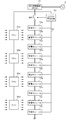
図3は、図1、図2の各蓄電モジュール10の回路構成例を示す図である。蓄電モジュール10は、蓄電部11、温度センサT1、シャント抵抗Rs、モジュール管理装置12を含む。蓄電部11は、直列接続された複数のセルS1−1nを含む。セルには、リチウムイオン電池セル、ニッケル水素電池セル、電気二重層キャパシタセル、リチウムイオンキャパシタセル等を用いることができる。以下、本明細書ではリチウムイオン電池セル(公称電圧:3.6−3.7V)を使用する例を想定する。なお蓄電部11は、直列接続された複数のセルを含む例に限らず、直並列接続された複数のセルを含む構成であってもよい。
FIG. 3 is a diagram showing a circuit configuration example of each
複数のセルS1−Snと直列にシャント抵抗Rsが接続される。シャント抵抗Rsは電流検出素子として機能する。なおシャント抵抗Rsの代わりにホール素子を用いてもよい。複数のセルS1−Snの近傍に、複数のセルS1−Snの温度を検出するための温度センサT1が設置される。温度センサT1には例えば、サーミスタを使用することができる。図3には温度センサT1が1つしか描かれていないが、温度センサT1は1つの蓄電モジュール10内に複数(例えば、3〜5個)設置されてもよい。
Shunt resistors Rs are connected in series with a plurality of cells S1-Sn. The shunt resistor Rs functions as a current detection element. A Hall element may be used instead of the shunt resistor Rs. A temperature sensor T1 for detecting the temperature of the plurality of cells S1-Sn is installed in the vicinity of the plurality of cells S1-Sn. For example, a thermistor can be used for the temperature sensor T1. Although only one temperature sensor T1 is drawn in FIG. 3, a plurality of (for example, 3 to 5) temperature sensors T1 may be installed in one
モジュール管理装置12は電圧検出部12a、温度検出部12b、電流検出部12c、制御部12d、通信部12e、記憶部12fを備える。電圧検出部12aは複数のセルS1−Snのそれぞれの電圧を検出して制御部12dに出力する。温度検出部12bは温度センサT1の出力値をもとに複数のセルS1−Snの温度を推定して制御部12dに出力する。温度センサT1が複数設置される場合、複数の温度センサT1の出力値の平均を算出して、複数のセルS1−Snの温度を推定する。電流検出部12cは、シャント抵抗Rsの両端に接続された誤差増幅器を含み、誤差増幅器はシャント抵抗Rsの両端電圧を検出する。電流検出部12cは当該両端電圧をもとに、蓄電部11に流れる電流を検出して制御部12dに出力する。
The
制御部12dは、電圧検出部12a、電流検出部12c、温度検出部12bにより検出された複数のセルS1−Snの電圧、電流、温度をもとに蓄電部11を管理する。例えば、複数のセルS1−SnのSOC(State Of Charge)管理、均等化制御などを実行する。
The
制御部12dの構成は、ハードウェア資源とソフトウェア資源の協働、またはハードウェア資源のみにより実現できる。ハードウェア資源として、マイクロコンピュータ、DSP、FPGA、その他のLSIを利用できる。ソフトウェア資源としてファームウェア等のプログラムを利用できる。記憶部12fはROM、及びRAMで実現できる。
The configuration of the
制御部12dはセルS1−SnのSOCを推定する。SOCは例えば、OCV(Open Circuit Voltage)法および/または電流積算法により推定できる。リチウムイオン電池ではSOCとOCVとの間に安定的な関係がある。従って、セルS1−Snに電流が流れていない状態において各セルS1−Snの両端電圧を検出することにより、各セルS1−SnのSOCを推定することができる。セルS1−Snに電流が流れている間は、電流積算法によりSOCの増減を推定することができる。記憶部12fは、各種のプログラム、データ、参照テーブル等を記憶する。
The
通信部12eは所定の通信制御処理(例えば、TCP/IP、RS−485等の規格に準拠した通信制御処理)を実行し、通信線40を介して他の蓄電モジュール10及び/又はシステム管理装置22と通信する。通信線40には、メタルケーブルを使用してもよいし、光ファイバケーブルを使用してもよい。
The
システム管理装置22は、複数の蓄電モジュール10a−10jから取得した電圧、電流、温度又はSOCの情報をもとにスイッチSW1を制御する。またシステム管理装置22は、複数の蓄電モジュール10a−10jから取得した温度をもとに、複数のファン30a−30dを制御する。システム管理装置22は、取得した温度の平均値が設定値(例えば、28℃)を超えているとき複数のファン30a−30dを駆動させ、当該平均値が当該設定値以下のとき複数のファン30a−30dを停止させる。なお、特定の蓄電モジュール10の温度のみが当該設定値を超えている場合、当該蓄電モジュール10に隣接する1つ又は2つのファン30のみを稼働させてもよい。
The
リチウムイオン電池セルの内部抵抗は、環境温度が低いほど増加する。従って電池の保護や寿命予測をするうえでは、蓄電モジュール10の筐体外の外気温度を考慮する必要がある。また蓄電モジュール10や電力変換装置21の耐圧、許容電流の設計は一定の環境温度範囲(例えば、18℃−28℃)を基準に設定されており、当該温度範囲外の高温または低温環境下で長時間使用した場合、動作不良が発生する場合がある。また高温環境下で使用される場合、仕様書の電池容量と比較して実際の容量が低下する。電池メーカは、適正な環境温度下での使用を前提に動作保証を行うため、蓄電システム1がユーザにより適正な環境温度下で使用されているかを把握しておく必要がある。
The internal resistance of a lithium-ion battery cell increases as the environmental temperature decreases. Therefore, in order to protect the battery and predict the life, it is necessary to consider the outside air temperature outside the housing of the
しかしながら、安全性、信頼性、経済性の観点から、外気温度を計測する温度センサを筐体の外部に取り付けるのは望ましくない。また、FR等の連続運転をする蓄電モジュール10も外気温度を推測する必要がある。
However, from the viewpoint of safety, reliability, and economy, it is not desirable to attach a temperature sensor that measures the outside air temperature to the outside of the housing. Further, it is also necessary to estimate the outside air temperature of the
そこで本実施の形態では制御部12dは、ファン30a−30dが稼働した状態で検出される所定期間あたりの検出温度の変化量ΔT_fanonと、ファン30a−30dが停止した状態で検出される所定期間あたりの検出温度の変化量ΔT_fanoffをもとに、蓄電モジュール10の筐体外の外気温度T_oを推定する。所定期間は例えば、1時間、2時間、4時間、6時間などに設定する。
Therefore, in the present embodiment, the
ファン30a−30dは、空気の流れを変えて気流を発生させる装置であり、空気の温度自体を変えるものではない。従って蓄電モジュール10に送風される空気の温度は、吸気される空気の温度と基本的に同じであり、ファン30a−30dによる蓄電モジュール10の冷却効果は環境温度に依存する。逆に言えば、ファン30a−30dによる蓄電モジュール10の冷却効果から逆算して環境温度を推定することができる。
The
制御部12dは、下記(式1)の関数をもとに外気温度T_oを推定する。
T_o=f(ΔT_fanon,ΔT_fanoff) ・・・(式1)The
T_o = f (ΔT_fanon, ΔT_fanoff) ... (Equation 1)
上記関数を実現するため例えば、制御部12dは、検出温度の変化量ΔT_fanon及び検出温度の変化量ΔT_fanoffを入力変数とし、外気温度T_oを出力変数とするテーブルを参照して、外気温度T_oを推定する。
In order to realize the above function, for example, the
図4(a)は、外気温度T_oを推定するための参照テーブル12faの第1例を示す図である。設計者は、実験やシミュレーションをもとに当該参照テーブル12faを生成する。例えば環境温度を25℃に設定し、ファン30a−30dを稼働した状態で1時間に発生する温度センサT1で検出される温度の変化量と、ファン30a−30dを停止させた状態で1時間に発生する温度センサT1で検出される温度の変化量を測定し、記録する。これを想定する全ての環境温度で実行することにより、上記参照テーブル12faが完成する。
FIG. 4A is a diagram showing a first example of the reference table 12fa for estimating the outside air temperature T_o. The designer generates the reference table 12fa based on experiments and simulations. For example, when the ambient temperature is set to 25 ° C., the amount of temperature change detected by the temperature sensor T1 that occurs in 1 hour when the
外気温度T_oの推定精度を高くするため、充放電電流を入力変数に加えることもできる。制御部12dは、ファン30a−30dが稼働した状態で検出される所定期間あたりの検出温度の変化量ΔT_fanonと、ファン30a−30dが停止した状態で検出される所定期間あたりの検出温度の変化量ΔT_fanoffと、蓄電部11に流れる電流Iをもとに、蓄電モジュール10の筐体外の外気温度T_oを推定する。
In order to improve the estimation accuracy of the outside air temperature T_o, the charge / discharge current can be added to the input variable. The
制御部12dは、下記(式2)の関数をもとに外気温度T_oを推定する。
T_o=f(ΔT_fanon,ΔT_fanoff,I) ・・・(式2)The
T_o = f (ΔT_fanon, ΔT_fanoff, I) ... (Equation 2)
上記関数を実現するため例えば、制御部12dは、検出温度の変化量ΔT_fanon、検出温度の変化量ΔT_fanoff、充放電電流Iを入力変数とし、外気温度T_oを出力変数とするテーブルを参照して、外気温度T_oを推定する。
In order to realize the above function, for example, the
図4(b)は、外気温度T_oを推定するための参照テーブル12fbの第2例を示す図である。設計者は、実験やシミュレーションをもとに当該参照テーブル12fbを生成する。設計者は、図4(a)に示した参照テーブルを充放電電流ごとに生成する。例えば、1A刻みで各電流値における参照テーブルを生成する。その際、充電電流は正の値、放電電流は負の値として参照テーブルを生成する。温度検出中は、充放電電流(充放電レート)は一定とする。 FIG. 4B is a diagram showing a second example of the reference table 12fb for estimating the outside air temperature T_o. The designer generates the reference table 12fb based on experiments and simulations. The designer generates the reference table shown in FIG. 4A for each charge / discharge current. For example, a reference table for each current value is generated in 1A increments. At that time, the reference table is generated with the charge current as a positive value and the discharge current as a negative value. During temperature detection, the charge / discharge current (charge / discharge rate) is constant.
外気温度T_oの推定精度が高くする必要がない用途では(例えば、正常な環境温度下で使用されているか否かの確認用途)、入力変数を単純化したモデルを使用することもできる。制御部12dは、所定期間あたりの検出温度の変化量ΔTと、所定期間中に蓄電部11に流れる電流Iの充放電レートをもとに、蓄電モジュール10の筐体外の外気温度T_oを推定する。この場合、ファン30が設置されない蓄電システム1でも、外気温度T_oを推定することができる。
For applications where the estimation accuracy of the outside air temperature T_o does not need to be high (for example, for checking whether or not the product is used under a normal environmental temperature), a model with simplified input variables can also be used. The
制御部12dは、下記(式3)の関数をもとに外気温度T_oを推定する。
T_o=f(ΔT,I) ・・・(式3)The
T_o = f (ΔT, I) ... (Equation 3)
以上説明したように本実施の形態によれば、筐体内に設置された温度センサT1の検出温度の変化量をもとに筐体外の温度を推定することにより、蓄電システムの外部温度を、温度センサを外部に設置することなく取得することができる。外部に温度センサを設置する必要がないためコストを削減することができる。また温度センサが外部からの物理的衝撃により壊れることがなくなるため信頼性が向上する。 As described above, according to the present embodiment, the temperature outside the housing is estimated based on the amount of change in the detected temperature of the temperature sensor T1 installed inside the housing, so that the external temperature of the power storage system is set to the temperature. It can be acquired without installing the sensor outside. Since it is not necessary to install a temperature sensor externally, the cost can be reduced. In addition, the temperature sensor is not damaged by an external physical impact, which improves reliability.
以上、本発明を実施の形態をもとに説明した。実施の形態は例示であり、それらの各構成要素や各処理プロセスの組み合わせにいろいろな変形例が可能なこと、またそうした変形例も本発明の範囲にあることは当業者に理解されるところである。 The present invention has been described above based on the embodiments. Embodiments are examples, and it will be understood by those skilled in the art that various modifications are possible for each of these components and combinations of each processing process, and that such modifications are also within the scope of the present invention. ..
上述の実施の形態では、空冷により蓄電モジュール10を冷却する構成を説明したが、液冷により蓄電モジュール10を冷却する構成にも適用することができる。例えば、循環用の冷媒(例えば、水)が環境温度により変化する場合、上述した実施の形態と同様に、液冷による蓄電モジュール10の冷却効果から環境温度を逆推定することができる。
In the above-described embodiment, the configuration in which the
また上述の実施の形態では蓄電システム1が、直列接続された複数の蓄電モジュール10a−10jを備える例を説明したが、蓄電モジュール10は1つであってもよい。その場合、システム管理装置22は不要であり、制御部12dが直接、ファン30を制御する。
Further, in the above-described embodiment, the example in which the power storage system 1 includes a plurality of
上記(式2)の関数では、所定期間あたりの検出温度の変化量ΔT_fanonと、ファン30a−30dが停止した状態で検出される所定期間あたりの検出温度の変化量ΔT_fanoffに加えて、充放電電流Iを入力変数とする例を挙げた。この点、充放電電流Iに変えて、内部抵抗R、SOC、SOH(State Of Health)等の変数を使用してもよい。
In the function of the above (Equation 2), in addition to the change amount ΔT_fanon of the detected temperature per predetermined period and the change amount ΔT_fanoff of the detected temperature per predetermined period detected when the
例えば、内部抵抗Rを使用する場合、制御部12dは、下記(式4)の関数をもとに外気温度T_oを推定する。
T_o=f(ΔT_fanon,ΔT_fanoff,R) ・・・(式4)For example, when the internal resistance R is used, the
T_o = f (ΔT_fanon, ΔT_fanoff, R) ... (Equation 4)
また充放電電流I、内部抵抗R、SOC、SOHの2つ以上を入力変数としてもよい。入力変数を多くするほど参照テーブルの規模が大きくなるが、外気温度T_oの推定精度を向上させることができる。 Further, two or more of the charge / discharge current I, the internal resistance R, the SOC, and the SOH may be used as input variables. The larger the number of input variables, the larger the scale of the reference table, but the accuracy of estimating the outside air temperature T_o can be improved.
なお、実施の形態は、以下の項目によって特定されてもよい。 The embodiment may be specified by the following items.
[項目1]
筐体内に設置されている蓄電部(11)と、
前記筐体内に設置されており、前記蓄電部(11)の温度を検出する温度検出部(T1、12b)と、
前記温度検出部(T1、12b)により検出される前記蓄電部(11)の検出温度をもとに、前記筐体外の温度を推定する制御部(12d)と、を備え、
前記制御部(12d)は、冷却部(30)が稼働した状態で検出される所定期間あたりの前記検出温度の変化量と、前記冷却部(30)が停止した状態で検出される所定期間あたりの前記検出温度の変化量をもとに、前記筐体外の外気温度を推定することを特徴とする蓄電装置(10)。
これによれば、筐体外に温度センサを設置しなくても、筐体外の外気温度を推定することができる。
[項目2]
前記制御部(12d)は、前記冷却部(30)が稼働した状態で検出される所定期間あたりの前記検出温度の変化量と、前記冷却部(30)が停止した状態で検出される所定期間あたりの前記検出温度の変化量を入力変数とし、外気温度を出力変数とするテーブル(12fa)を参照して、前記外気温度を推定することを特徴とする項目1に記載の蓄電装置(10)。
これによれば、テーブル参照により、簡単に外気温度を推定することができる。
[項目3]
前記蓄電部(11)に流れる電流を検出する電流検出部(12c)をさらに備え、
前記制御部(12d)は、前記冷却部(30)が稼働した状態で検出される所定期間あたりの前記検出温度の変化量と、前記冷却部(30)が停止した状態で検出される所定期間あたりの前記検出温度の変化量と、前記蓄電部(11)に流れる電流をもとに、前記筐体外の外気温度を推定することを特徴とする項目1に記載の蓄電装置(10)。
これによれば、外気温度の推定精度を向上させることができる。
[項目4]
前記制御部(12d)は、冷却部(30)が稼働した状態で検出される所定期間あたりの前記検出温度の変化量と、前記冷却部(30)が停止した状態で検出される所定期間あたりの前記検出温度の変化量と、前記蓄電部(11)の内部抵抗をもとに、前記筐体外の外気温度を推定することを特徴とする項目1に記載の蓄電装置(10)。
これによれば、外気温度の推定精度を向上させることができる。
[項目5]
前記冷却部(30)は、前記筐体外に設置されるファン(30)であることを特徴とする項目1から4のいずれに記載の蓄電装置(10)。
これによれば、外気を吸気して蓄電部(11)に向けて排気しているファン(30)の冷却効果から、外気温度を逆推定することができる。
[項目6]
筐体内に設置されている蓄電部(11)と、
前記筐体内に設置されており、前記蓄電部(11)の温度を検出する温度検出部(T1、12b)と、
前記蓄電部(11)に流れる電流を検出する電流検出部(12c)と、
前記温度検出部(T1、12b)により検出される検出温度と、前記電流検出部(12c)により検出される電流をもとに、前記筐体外の温度を推定する制御部(12d)と、を備え、
前記制御部(12d)は、所定期間あたりの前記検出温度の変化量と、前記所定期間中に流れる電流をもとに、前記筐体外の外気温度を推定することを特徴とする蓄電装置(10)。
これによれば、筐体外に温度センサ及びファンを設置しなくても、筐体外の外気温度を推定することができる。
[項目7]
筐体内に設置されている蓄電部(11)の温度を検出する温度検出部(T1、12b)と、
前記温度検出部(T1、12b)により検出される前記蓄電部(11)の検出温度をもとに、前記筐体外の温度を推定する制御部(12d)と、を備え、
前記制御部(12d)は、冷却部(30)が稼働した状態で検出される所定期間あたりの前記検出温度の変化量と、前記冷却部(30)が停止した状態で検出される所定期間あたりの前記検出温度の変化量をもとに、前記筐体外の外気温度を推定することを特徴とする管理装置(12)。
これによれば、筐体外に温度センサを設置しなくても、筐体外の外気温度を推定することができる。[Item 1]
The power storage unit (11) installed in the housing and
A temperature detection unit (T1, 12b) installed in the housing and detecting the temperature of the power storage unit (11), and
A control unit (12d) that estimates the temperature outside the housing based on the detected temperature of the power storage unit (11) detected by the temperature detection units (T1, 12b) is provided.
The control unit (12d) has a change amount of the detected temperature per predetermined period detected while the cooling unit (30) is operating and a predetermined period detected when the cooling unit (30) is stopped. A power storage device (10), characterized in that the outside air temperature outside the housing is estimated based on the amount of change in the detected temperature.
According to this, the outside air temperature outside the housing can be estimated without installing the temperature sensor outside the housing.
[Item 2]
The control unit (12d) has a change amount of the detected temperature per predetermined period detected while the cooling unit (30) is operating and a predetermined period detected when the cooling unit (30) is stopped. The power storage device (10) according to item 1, wherein the outside air temperature is estimated by referring to a table (12fa) in which the amount of change in the detected temperature is used as an input variable and the outside air temperature is used as an output variable. ..
According to this, the outside air temperature can be easily estimated by referring to the table.
[Item 3]
A current detection unit (12c) for detecting the current flowing through the power storage unit (11) is further provided.
The control unit (12d) has a change amount of the detected temperature per predetermined period detected while the cooling unit (30) is operating and a predetermined period detected when the cooling unit (30) is stopped. The power storage device (10) according to item 1, wherein the outside air temperature outside the housing is estimated based on the amount of change in the detected temperature and the current flowing through the power storage unit (11).
According to this, the estimation accuracy of the outside air temperature can be improved.
[Item 4]
The control unit (12d) has a change amount of the detected temperature per predetermined period detected while the cooling unit (30) is operating and a predetermined period detected when the cooling unit (30) is stopped. The power storage device (10) according to item 1, wherein the outside air temperature outside the housing is estimated based on the amount of change in the detected temperature and the internal resistance of the power storage unit (11).
According to this, the estimation accuracy of the outside air temperature can be improved.
[Item 5]
The power storage device (10) according to any one of items 1 to 4, wherein the cooling unit (30) is a fan (30) installed outside the housing.
According to this, the outside air temperature can be reversely estimated from the cooling effect of the fan (30) that takes in the outside air and exhausts it toward the power storage unit (11).
[Item 6]
The power storage unit (11) installed in the housing and
A temperature detection unit (T1, 12b) installed in the housing and detecting the temperature of the power storage unit (11), and
A current detection unit (12c) that detects the current flowing through the power storage unit (11), and a current detection unit (12c).
A control unit (12d) that estimates the temperature outside the housing based on the detection temperature detected by the temperature detection units (T1, 12b) and the current detected by the current detection unit (12c). Prepare,
The power storage device (10) is characterized in that the control unit (12d) estimates the outside air temperature outside the housing based on the amount of change in the detected temperature per predetermined period and the current flowing during the predetermined period. ).
According to this, the outside air temperature outside the housing can be estimated without installing the temperature sensor and the fan outside the housing.
[Item 7]
Temperature detection units (T1, 12b) that detect the temperature of the power storage unit (11) installed in the housing, and
A control unit (12d) that estimates the temperature outside the housing based on the detected temperature of the power storage unit (11) detected by the temperature detection units (T1, 12b) is provided.
The control unit (12d) has a change amount of the detected temperature per predetermined period detected while the cooling unit (30) is operating and a predetermined period detected when the cooling unit (30) is stopped. A management device (12) characterized in that the outside air temperature outside the housing is estimated based on the amount of change in the detected temperature.
According to this, the outside air temperature outside the housing can be estimated without installing the temperature sensor outside the housing.
1 蓄電システム、 1f ラックフレーム、 1p ファン取付板、 2 系統、 10 蓄電モジュール、 11 蓄電部、 12 モジュール管理装置、 12a 電圧検出部、 12b 温度検出部、 12c 電流検出部、 12d 制御部、 12e 通信部、 12f 記憶部、 S1−Sn セル、 Rs シャント抵抗、 T1 温度センサ、 SW1 スイッチ、 20 回路装置、 21 電力変換装置、 22 システム管理装置、 30 ファン、 40 通信線。 1 power storage system, 1f rack frame, 1p fan mounting plate, 2 systems, 10 power storage module, 11 power storage unit, 12 module management device, 12a voltage detection unit, 12b temperature detection unit, 12c current detection unit, 12d control unit, 12e communication Unit, 12f storage unit, S1-Sn cell, Rs shunt resistance, T1 temperature sensor, SW1 switch, 20 circuit equipment, 21 power converter, 22 system management equipment, 30 fans, 40 communication lines.
Claims (7)
前記筐体内に設置されており、前記蓄電部の温度を検出する温度検出部と、
前記温度検出部により検出される前記蓄電部の検出温度をもとに、前記筐体外の温度を推定する制御部と、を備え、
前記制御部は、冷却部が稼働した状態で検出される所定期間あたりの前記検出温度の変化量と、前記冷却部が停止した状態で検出される所定期間あたりの前記検出温度の変化量をもとに、前記筐体外の外気温度を推定することを特徴とする蓄電装置。The power storage unit installed in the housing and
A temperature detection unit installed in the housing and detecting the temperature of the power storage unit,
A control unit that estimates the temperature outside the housing based on the detection temperature of the power storage unit detected by the temperature detection unit is provided.
The control unit also has a change amount of the detected temperature per predetermined period detected when the cooling unit is operating and a change amount of the detected temperature per predetermined period detected when the cooling unit is stopped. A power storage device that estimates the outside air temperature outside the housing.
前記制御部は、前記冷却部が稼働した状態で検出される所定期間あたりの前記検出温度の変化量と、前記冷却部が停止した状態で検出される所定期間あたりの前記検出温度の変化量と、前記蓄電部に流れる電流をもとに、前記筐体外の外気温度を推定することを特徴とする請求項1に記載の蓄電装置。A current detection unit that detects the current flowing through the power storage unit is further provided.
The control unit includes the amount of change in the detected temperature per predetermined period detected when the cooling unit is operating, and the amount of change in the detected temperature per predetermined period detected when the cooling unit is stopped. The power storage device according to claim 1, wherein the outside air temperature outside the housing is estimated based on the current flowing through the power storage unit.
前記筐体内に設置されており、前記蓄電部の温度を検出する温度検出部と、
前記蓄電部に流れる電流を検出する電流検出部と、
前記温度検出部により検出される検出温度と、前記電流検出部により検出される電流をもとに、前記筐体外の温度を推定する制御部と、を備え、
前記制御部は、所定期間あたりの前記検出温度の変化量と、前記所定期間中に流れる電流をもとに、前記筐体外の外気温度を推定することを特徴とする蓄電装置。The power storage unit installed in the housing and
A temperature detection unit installed in the housing and detecting the temperature of the power storage unit,
A current detection unit that detects the current flowing through the power storage unit, and
A control unit that estimates the temperature outside the housing based on the detection temperature detected by the temperature detection unit and the current detected by the current detection unit is provided.
The control unit is a power storage device that estimates the outside air temperature outside the housing based on the amount of change in the detected temperature per predetermined period and the current flowing during the predetermined period.
前記温度検出部により検出される前記蓄電部の検出温度をもとに、前記筐体外の温度を推定する制御部と、を備え、
前記制御部は、冷却部が稼働した状態で検出される所定期間あたりの前記検出温度の変化量と、前記冷却部が停止した状態で検出される所定期間あたりの前記検出温度の変化量をもとに、前記筐体外の外気温度を推定することを特徴とする管理装置。A temperature detector that detects the temperature of the power storage unit installed in the housing,
A control unit that estimates the temperature outside the housing based on the detection temperature of the power storage unit detected by the temperature detection unit is provided.
The control unit also has a change amount of the detected temperature per predetermined period detected when the cooling unit is operating and a change amount of the detected temperature per predetermined period detected when the cooling unit is stopped. In addition, a management device characterized in that the outside air temperature outside the housing is estimated.
Applications Claiming Priority (3)
| Application Number | Priority Date | Filing Date | Title |
|---|---|---|---|
| JP2016111262 | 2016-06-02 | ||
| JP2016111262 | 2016-06-02 | ||
| PCT/JP2017/018313 WO2017208805A1 (en) | 2016-06-02 | 2017-05-16 | Electricity storage device and management device |
Publications (2)
| Publication Number | Publication Date |
|---|---|
| JPWO2017208805A1 JPWO2017208805A1 (en) | 2019-03-28 |
| JP6872706B2 true JP6872706B2 (en) | 2021-05-19 |
Family
ID=60479402
Family Applications (1)
| Application Number | Title | Priority Date | Filing Date |
|---|---|---|---|
| JP2018520773A Active JP6872706B2 (en) | 2016-06-02 | 2017-05-16 | Power storage device and management device |
Country Status (3)
| Country | Link |
|---|---|
| US (1) | US11081744B2 (en) |
| JP (1) | JP6872706B2 (en) |
| WO (1) | WO2017208805A1 (en) |
Family Cites Families (10)
| Publication number | Priority date | Publication date | Assignee | Title |
|---|---|---|---|---|
| JPH09159541A (en) * | 1995-12-12 | 1997-06-20 | Oki Electric Ind Co Ltd | Temperature detecting method and printer device having temperature detecting function |
| JP3455832B2 (en) * | 1996-02-19 | 2003-10-14 | 日本電気エンジニアリング株式会社 | Backup storage battery charger |
| JP2002108483A (en) * | 2000-10-02 | 2002-04-10 | Hitachi Ltd | Method for controlling information processor and information processor |
| JP2009265280A (en) * | 2008-04-23 | 2009-11-12 | Canon Inc | Image forming device and control method therefor |
| JP2012191770A (en) * | 2011-03-11 | 2012-10-04 | Yamaha Corp | Electric equipment power management device |
| JP2013200979A (en) | 2012-03-23 | 2013-10-03 | Sanyo Electric Co Ltd | Control device |
| US10170811B2 (en) * | 2013-01-14 | 2019-01-01 | Gentherm Incorporated | Thermoelectric-based thermal management of electrical devices |
| JP2014171002A (en) | 2013-03-01 | 2014-09-18 | Nikon Corp | Image pickup device |
| JP2014187807A (en) * | 2013-03-22 | 2014-10-02 | Toyota Motor Corp | Power storage system |
| JP6096633B2 (en) * | 2013-10-03 | 2017-03-15 | 株式会社日立産機システム | Water supply device and inverter for controlling synchronous motor for driving pump used therefor |
-
2017
- 2017-05-16 JP JP2018520773A patent/JP6872706B2/en active Active
- 2017-05-16 US US16/097,681 patent/US11081744B2/en active Active
- 2017-05-16 WO PCT/JP2017/018313 patent/WO2017208805A1/en active Application Filing
Also Published As
| Publication number | Publication date |
|---|---|
| JPWO2017208805A1 (en) | 2019-03-28 |
| WO2017208805A1 (en) | 2017-12-07 |
| US11081744B2 (en) | 2021-08-03 |
| US20200365957A1 (en) | 2020-11-19 |
Similar Documents
| Publication | Publication Date | Title |
|---|---|---|
| JP6162884B2 (en) | Battery pack, control circuit, and control method | |
| JP6564647B2 (en) | Battery degradation state estimation device and degradation state estimation method thereof | |
| JP5687340B2 (en) | Battery control device, battery system | |
| US8994339B1 (en) | Battery temperature compensation with closed-loop fan control | |
| EP2883266B1 (en) | Battery pack condensation prevention | |
| JP7054868B2 (en) | Battery management system, battery system, and vehicle power supply system | |
| EP2543107A2 (en) | Thermal sensor device with average temperature and hot spot feedback | |
| JP6168962B2 (en) | Abnormality determination device, charge / discharge information presentation device, secondary battery module, abnormality determination method, and program | |
| WO2017203985A1 (en) | Power storage system and management device | |
| JPWO2019039120A1 (en) | Power storage system and management device | |
| JP2017156272A (en) | Deteriorated state estimating device for batteries, and deteriorated state estimating method for the device | |
| JPWO2019163301A1 (en) | Management device, power storage system | |
| JP6790102B2 (en) | Management device and power storage system | |
| KR102072247B1 (en) | Temperature management system of battery pack and method thereof | |
| JP2013005663A (en) | Battery pack input-output controller | |
| US20210242512A1 (en) | Method for determining a status of the thermal connection of at least one component within an electrical energy storage system to a heat source or heat sink | |
| JP6872706B2 (en) | Power storage device and management device | |
| US11564328B2 (en) | Louver design for battery backup units | |
| JP6773889B2 (en) | Battery deterioration predictor, battery system, method and program | |
| JP7124596B2 (en) | Battery temperature sensor abnormality detection device | |
| JP7240893B2 (en) | battery controller | |
| KR20210098216A (en) | Battery module and controlling method of battery protection unit | |
| JP2021096976A (en) | Power storage system | |
| JP2020057521A (en) | Battery pack |
Legal Events
| Date | Code | Title | Description |
|---|---|---|---|
| A621 | Written request for application examination |
Free format text: JAPANESE INTERMEDIATE CODE: A621 Effective date: 20200124 |
|
| TRDD | Decision of grant or rejection written | ||
| A01 | Written decision to grant a patent or to grant a registration (utility model) |
Free format text: JAPANESE INTERMEDIATE CODE: A01 Effective date: 20210309 |
|
| A61 | First payment of annual fees (during grant procedure) |
Free format text: JAPANESE INTERMEDIATE CODE: A61 Effective date: 20210331 |
|
| R151 | Written notification of patent or utility model registration |
Ref document number: 6872706 Country of ref document: JP Free format text: JAPANESE INTERMEDIATE CODE: R151 |