JP6871447B2 - Moving image coding method and moving image decoding method - Google Patents
Moving image coding method and moving image decoding method Download PDFInfo
- Publication number
- JP6871447B2 JP6871447B2 JP2020016204A JP2020016204A JP6871447B2 JP 6871447 B2 JP6871447 B2 JP 6871447B2 JP 2020016204 A JP2020016204 A JP 2020016204A JP 2020016204 A JP2020016204 A JP 2020016204A JP 6871447 B2 JP6871447 B2 JP 6871447B2
- Authority
- JP
- Japan
- Prior art keywords
- motion information
- block
- prediction
- unit
- coding
- Prior art date
- Legal status (The legal status is an assumption and is not a legal conclusion. Google has not performed a legal analysis and makes no representation as to the accuracy of the status listed.)
- Active
Links
Images


Description
本発明の実施形態は、動画像の符号化及び復号化における動き情報圧縮方法、動画像符号化方法及び動画像復号化方法に関する。 An embodiment of the present invention relates to a motion information compression method, a moving image coding method, and a moving image decoding method in coding and decoding a moving image.
近年、大幅に符号化効率を向上させた画像符号化方法が、ITU-TとISO/IECとの共同で、ITU-T Rec. H.264及びISO/IEC 14496-10(以下、H.264という)として勧告されている。H.264では、予測処理、変換処理及びエントロピー符号化処理は、矩形ブロック単位(例えば、16×16画素ブロック単位、8×8画素ブロック単位等)で行われる。予測処理においては、符号化対象の矩形ブロック(符号化対象ブロック)に対して、既に符号化済みのフレーム(参照フレーム)を参照して、時間方向の予測を行う動き補償が行われる。このような動き補償では、符号化対象ブロックと参照フレーム内において参照されるブロックとの空間的シフト情報としての動きベクトルを含む動き情報を符号化して復号化側に送る必要がある。さらに、複数の参照フレームを用いて動き補償を行う場合、動き情報とともに参照フレーム番号も符号化する必要がある。このため、動き情報及び参照フレーム番号に関する符号量が増大する場合がある。また、参照フレームの動き情報メモリに格納されている動き情報を参照して、符号化対象ブロックの予測動き情報を導出する動き情報予測方法があり(特許文献1及び非特許文献2)、動き情報を格納する動き情報メモリの容量が増加する場合がある。
In recent years, image coding methods with significantly improved coding efficiency have been developed in collaboration with ITU-T and ISO / IEC, such as ITU-T Rec. H.264 and ISO / IEC 14496-10 (hereinafter, H.264). It is recommended as). In H.264, prediction processing, conversion processing, and entropy coding processing are performed in rectangular block units (for example, 16 × 16 pixel block units, 8 × 8 pixel block units, etc.). In the prediction process, motion compensation is performed on the rectangular block to be encoded (block to be encoded) by referring to the already encoded frame (reference frame) to make a prediction in the time direction. In such motion compensation, it is necessary to encode the motion information including the motion vector as the spatial shift information between the coded block and the block referenced in the reference frame and send it to the decoding side. Further, when motion compensation is performed using a plurality of reference frames, it is necessary to encode the reference frame number together with the motion information. Therefore, the amount of code related to the motion information and the reference frame number may increase. Further, there is a motion information prediction method for deriving the predicted motion information of the coded block by referring to the motion information stored in the motion information memory of the reference frame (
動き情報メモリの容量を削減する方法の一例として、(非特許文献2)では、予め定められたブロック内で代表する動き情報を導出し、代表する動き情報のみを動き情報メモリに格納する。 As an example of a method of reducing the capacity of the motion information memory, (Non-Patent Document 2) derives representative motion information in a predetermined block and stores only the representative motion information in the motion information memory.
しかしながら、非特許文献1で示される予測動き情報の導出方法と非特許文献2で示される代表動き情報の導出方法が異なる場合に、予測動き情報の時間相関が低減するために、動き情報に関する符号量が増加される問題がある。
However, when the method for deriving the predicted motion information shown in
本発明が解決しようとする課題は、上記問題点を解決するためになされたものであり、符号化効率を向上可能な動き情報圧縮装置を含んだ動画像符号化装置及び動画像復号化装置を提供することである。 The problem to be solved by the present invention is to solve the above-mentioned problems, and to provide a moving image coding device and a moving image decoding device including a motion information compression device capable of improving coding efficiency. To provide.
実施形態によれば、動画像符号化方法は、入力画像信号を画素ブロックに分割し、これら分割した画素ブロックに対してインター予測を行う方法である。この方法は、符号化済み領域における動き情報を保持する動き情報バッファの中から、予測動き情報を選択し、前記予測動き情報を用いて、符号化対象ブロックの動き情報を予測することを含み。さらに、この方法は符号化が終了した領域内の複数の動き情報の中から、前記予測動き情報の選択方法を示す第1情報に従って代表動き情報を取得し、前記代表動き情報のみを得ることを含む。 According to the embodiment, the moving image coding method is a method of dividing an input image signal into pixel blocks and performing inter-prediction for these divided pixel blocks. This method includes selecting predicted motion information from a motion information buffer that holds motion information in a coded region, and using the predicted motion information to predict motion information of a block to be encoded. Further, in this method, representative motion information is acquired from a plurality of motion information in the encoded region according to the first information indicating the method of selecting the predicted motion information, and only the representative motion information is obtained. Including.
以下、図面を参照して、各実施形態に係る動画像符号化装置及び動画像復号化装置について詳細に説明する。なお、以降の説明において、「画像」という用語は、「映像」「画素」「画像信号」、「画像データ」などの用語として適宜読み替えることができる。また、以下の実施形態では、同一の番号を付した部分については同様の動作を行うものとして、重ねての説明を省略する。
(第1の実施形態)
第1の実施形態は画像符号化装置に関する。本実施形態に係る画像符号化装置に対応する動画像復号化装置は、第2の実施形態において説明する。この画像符号化装置は、LSI(Large-Scale Integration)チップやDSP(Digital Signal Processor)、FPGA(Field Programmable Gate Array)などのハードウェアにより実現可能である。また、この画像符号化装置は、コンピュータに画像符号化プログラムを実行させることによっても実現可能である。
Hereinafter, the moving image coding device and the moving image decoding device according to each embodiment will be described in detail with reference to the drawings. In the following description, the term "image" can be appropriately read as a term such as "video", "pixel", "image signal", and "image data". Further, in the following embodiments, the same operation is performed for the portions with the same number, and the description thereof will be omitted.
(First Embodiment)
The first embodiment relates to an image coding device. The moving image decoding device corresponding to the image coding device according to the present embodiment will be described in the second embodiment. This image coding device can be realized by hardware such as an LSI (Large-Scale Integration) chip, a DSP (Digital Signal Processor), and an FPGA (Field Programmable Gate Array). This image coding device can also be realized by causing a computer to execute an image coding program.
図1に示すように、本実施形態に係る画像符号化装置100は、減算部101、直交変換部102、量子化部103、逆量子化部104、逆直交変換部105、加算部106、参照画像メモリ107、インター予測部108、動き情報圧縮部109、動き情報メモリ110、及びエントロピー符号化部112を含む。符号化制御部114、及び出力バッファ113は通常、画像符号化装置100の外部に設置される。
As shown in FIG. 1, the
図1の画像符号化装置100は、入力画像信号151を構成する各フレームまたは各フィールドまたは各スライスを複数の画素ブロックに分割し、これら分割した画素ブロックに対して予測符号化を行って、符号化データ163を出力する。以降の説明では、簡単化のために、図2Aに示されるように左上から右下に向かって画素ブロックの予測符号化が行われることを仮定する。図2Aでは、符号化処理対象のフレームfにおいて、符号化対象画素ブロックcよりも左側及び上側に符号化済み画素ブロックpが位置している。
The
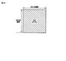
ここで、画素ブロックは、例えば、M×Nサイズのブロック(N及びMは自然数)、コーディングユニット、マクロブロック、サブブロック、1画素などの画像を処理する単位を指す。なお、以降の説明では、画素ブロックをコーディングユニットの意味で基本的に使用するが、説明を適宜読み替えることにより画素ブロックを上述した意味で解釈することも可能である。コーディングユニットは、典型的には、例えば図2Bに示す16×16画素ブロックであるが、図2Cに示す32×32画素ブロック、図2Dに示す64×64画素ブロックであってもよいし、図示しない8×8画素ブロック、4×4画素ブロックであってもよい。また、コーディングユニットは必ずしも正方形である必要はない。以下、入力画像信号151の符号化対象ブロックもしくはコーディングニットを「予測対象ブロック」と称することもある。また、符号化単位には、コーディングユニットのような画素ブロックに限らず、フレームまたはフィールド、スライス、或いはこれらの組み合わせを用いることができる。
Here, the pixel block refers to a unit for processing an image such as an M × N size block (N and M are natural numbers), a coding unit, a macro block, a sub block, and one pixel. In the following description, the pixel block is basically used in the meaning of the coding unit, but the pixel block can be interpreted in the above-mentioned meaning by appropriately reading the description. The coding unit is typically, for example, a 16 × 16 pixel block shown in FIG. 2B, but may be a 32 × 32 pixel block shown in FIG. 2C, a 64 × 64 pixel block shown in FIG. 2D, or is shown. It may be an 8 × 8 pixel block or a 4 × 4 pixel block. Also, the coding unit does not necessarily have to be square. Hereinafter, the coding target block or coding knit of the
図3Aから図3Dまでは、コーディングユニットの具体例を示した図である。図3Aは、コーディングユニットのサイズが64×64(N=32)の場合の例を示している。ここでNは、基準となるコーディングユニットのサイズを表しており、分割された場合のサイズをNと定義し、分割されない場合を2Nと定義する。コーディングツリーユニットは四分木構造を持ち、分割された場合は、4つの画素ブロックに対してZスキャン順でインデックスが付される。図3Bに、図3Aの64x64画素ブロックを四分木分割した例を示す。図中に示される番号がZスキャンの順番を表している。また、コーディングユニットの1つの四分木のインデックス内でさらに四分木分割することが可能である。分割の深さをDepthで定義する。つまり、図3AはDepth=0の例を示している。図3CにDepth=1の場合の32×32(N=16)サイズのコーディングツリーユニットの例を示す。このようなコーディングツリーユニットの最も大きいユニットをラージコーディングツリーユニット若しくはツリーブロックと呼び、図2Aに示すように、この単位で入力画像信号がラスタースキャン順に符号化される。 3A to 3D are diagrams showing specific examples of coding units. FIG. 3A shows an example when the size of the coding unit is 64 × 64 (N = 32). Here, N represents the size of the reference coding unit, and the size when divided is defined as N, and the case where it is not divided is defined as 2N. The coding tree unit has a quadtree structure, and when divided, the four pixel blocks are indexed in Z-scan order. FIG. 3B shows an example in which the 64x64 pixel block of FIG. 3A is divided into quadtrees. The numbers shown in the figure indicate the order of Z scans. It is also possible to further divide the quadtree within the index of one quadtree of the coding unit. The depth of division is defined by Depth. That is, FIG. 3A shows an example of Dept = 0. FIG. 3C shows an example of a coding tree unit having a size of 32 × 32 (N = 16) when Dept = 1. The largest unit of such a coding tree unit is called a large coding tree unit or a tree block, and as shown in FIG. 2A, the input image signal is encoded in the raster scan order in this unit.
図1の画像符号化装置100は、符号化制御部114から入力される符号化パラメータに基づいて、画素ブロックに対するインター予測(画面間予測、フレーム間予測、動き補償予測などとも称される)または図示されないイントラ予測(画面内予測、フレーム内予測などとも称される)を行って、予測画像信号159を生成する。この画像符号化装置100は、画素ブロック(入力画像信号151)と予測画像信号159との間の予測誤差信号152を直交変換及び量子化し、エントロピー符号化を行って符号化データ163を生成して出力する。
The
図1の画像符号化装置100は、ブロックサイズ及び予測画像信号159の生成方法の異なる複数の予測モードを選択的に適用して符号化を行う。予測画像信号159の生成方法は、大別すると、符号化対象フレーム内で予測を行うイントラ予測と、時間的に異なる1つまたは複数の参照フレームを用いて予測を行うインター予測との2種類である。
The
以下、図1の画像符号化装置100に含まれる各要素を説明する。
減算部101は、入力画像信号151の符号化対象ブロックから、対応する予測画像信号159を減算して予測誤差信号152を得る。減算部101は、予測誤差信号152を直交変換部102に入力する。
Hereinafter, each element included in the
The
直交変換部102は、減算部101からの予測誤差信号152に対して、例えば離散コサイン変換(DCT)のような直交変換を行い、変換係数153を得る。直交変換部102は、変換係数153を量子化部103に出力する。
The
量子化部103は、直交変換部102からの変換係数153に対して量子化を行い、量子化変換係数154を得る。具体的には、量子化部103は、符号化制御部114によって指定される量子化パラメータ、量子化マトリクスなどの量子化情報に従って量子化を行う。量子化パラメータは、量子化の細かさを示す。量子化マトリクスは、量子化の細かさを変換係数の成分毎に重み付けするために使用されるが、量子化マトリクスの使用・不使用は本発明の実施形態の本質部分ではない。量子化部103は、量子化変換係数154をエントロピー符号化部112及び逆量子化部104に出力する。
The
エントロピー符号化部112は、量子化部103からの量子化変換係数154、インター予測部108からの動き情報160、符号化制御部114によって指定される予測情報165、符号化制御部114からの参照位置情報164、量子化情報などの様々な符号化パラメータに対してエントロピー符号化(例えば、ハフマン符号化、算術符号化など)を行い、符号化データ163を生成する。なお、符号化パラメータとは、予測情報165、変換係数に関する情報、量子化に関する情報、などの復号に必要となるパラメータである。例えば、符号化制御部114が内部メモリ(図示しない)を持ち、このメモリに符号化パラメータが保持され、予測対象ブロックを符号化する際に隣接する既に符号化済みの画素ブロックの符号化パラメータを用いる。
The
具体的には、エントロピー符号化部112は、図4に示すように、パラメータ符号化部401、変換係数符号化部402、動き情報符号化部403、並びに多重化部404を備える。パラメータ符号化部401は、符号化制御部114から受け取った予測情報165などの符号化パラメータを符号化して符号化データ451Aを生成する。変換係数符号化部402は、量子化部103から受け取った量子化後の変換係数154を符号化して符号化データ451Bを生成する。
Specifically, as shown in FIG. 4, the
動き情報符号化部403は、動き情報メモリ110から受け取った参照動き情報166、符号化制御部114から受け取った参照位置情報164を参照して、インター予測部108から受け取った動き情報160を符号化して符号化データ451Cを生成する。動き情報符号化部403に関してはその詳細を後述する。
The motion
多重化部404は、符号化データ451A、451B、451Cを多重化して符号化データ163を生成する。生成された符号化データ163は、動き情報160、予測情報165とともに、変換係数に関する情報、量子化に関する情報などの復号の際に必要になるあらゆるパラメータを含む。
The
エントロピー符号化部112によって生成された符号化データ163は、例えば多重化を経て出力バッファ113に一時的に蓄積され、符号化制御部114が管理する適切な出力タイミングに従って符号化データ163として出力される。符号化データ163は、例えば、図示しない蓄積系(蓄積メディア)または伝送系(通信回線)へ出力される。
The coded
逆量子化部104は、量子化部103からの量子化変換係数154に対して逆量子化を行い、復元変換係数155を得る。具体的には、逆量子化部104は、量子化部103において使用された量子化情報に従って逆量子化を行う。量子化部103において使用された量子化情報は、符号化制御部114の内部メモリからロードされる。逆量子化部104は、復元変換係数155を逆直交変換部105に出力する。
The inverse quantization unit 104 performs inverse quantization on the
逆直交変換部105は、逆量子化部104からの復元変換係数155に対して、例えば逆離散コサイン変換などのような直交変換部102において行われた直交変換に対応する逆直交変換を行い、復元予測誤差信号156を得る。逆直交変換部105は、復元予測誤差信号156を加算部106に出力する。
The inverse
加算部106は、復元予測誤差信号156と、対応する予測画像信号159とを加算し、局所的な復号画像信号157を生成する。復号画像信号157は図示しないデブロッキングフィルタやウィナーフィルタなどを施し、参照画像メモリ107へと入力される。
The
参照画像メモリ107は、メモリに局部復号後の被フィルタ画像信号158を蓄積しておりインター予測部108によって必要に応じて予測画像を生成する際に、参照画像信号158として参照される。
The
インター予測部108は、参照画像メモリ107に保存されている参照画像信号158を利用してインター予測を行う。具体的には、インター予測部108は、予測対象ブロックと参照画像信号158との間でブロックマッチング処理を行って動きのズレ量(動きベクトル)を導出する。インター予測部108は、この動きベクトルに基づいて動き補償(小数精度の動きの場合は補間処理)を行ってインター予測画像を生成する。H.264では、1/4画素精度までの補間処理が可能である。導出された動きベクトルは動き情報160の一部としてエントロピー符号化される。
The
動き情報メモリ110は、動き情報圧縮部109を有し、動き情報160に対して適宜圧縮処理を行い情報量を削減し、参照動き情報166として一時的に格納する。図5に示されるように、動き情報メモリ110がフレーム(またはスライス)単位で保持されており、同一フレーム上の動き情報160を参照動き情報166として格納する空間方向参照動き情報メモリ501及び、既に符号化が終了したフレームの動き情報160を参照動き情報166として格納する時間方向参照動き情報メモリ502を更に有する。時間方向参照動き情報メモリ502は符号化対象フレームが予測に用いる参照フレームの数に応じて、複数有しても構わない。
The
また、空間方向参照動き情報メモリ501及び時間方向参照動き情報メモリ502は、物理的に同一のメモリを論理的に区切っても構わない。更に、空間方向参照動き情報メモリ501は、現在符号化を行っているフレームで必要な空間方向動き情報のみを保持し、参照が不要となった空間方向動き情報を順次圧縮して時間方向参照動き情報メモリ502に格納しても構わない。
Further, the spatial direction reference
参照動き情報166は、所定の領域単位(例えば、4×4画素ブロック単位)で空間方向参照動き情報メモリ501及び時間方向参照動き情報メモリ502内に保持される。参照動き情報166は、その領域が後述するインター予測で符号化されたのか或いは後述するイントラ予測で符号化されたのかを示す情報をさらに有する。また、コーディングユニット(又はプレディクションユニット)がH.264で規定されるスキップモード、ダイレクトモード若しくは後述するマージモードのように、動き情報160内の動きベクトルの値が符号化されず、符号化済みの領域から予測された動き情報160を用いてインター予測される場合においても、当該コーディングユニット(又はプレディクションユニット)の動き情報が参照動き情報166として保持される。
The
符号化対象のフレーム又はスライスの符号化処理が終了したら、当該フレームの空間方向参照動き情報メモリ501は、次に符号化処理を行うフレームに用いる時間方向参照動き情報メモリ502としてその扱いが変更される。この際、時間方向参照動き情報メモリ502のメモリ容量を削減するために、後述する動き情報圧縮部109によって圧縮された動き情報160を時間方向参照動き情報メモリ502に格納する。
When the coding process of the frame or slice to be encoded is completed, the spatial direction reference
予測情報165は符号化制御部114が制御する予測モードに従っており、前述のように、予測画像信号159の生成のためにインター予測または図示されないイントラ予測またはインター予測が選択可能であるが、イントラ予測及びインター予測の夫々に複数のモードがさらに選択可能である。符号化制御部114はイントラ予測及びインター予測の複数の予測モードのうちの1つを最適な予測モードとして判定し、予測情報165を設定する。
The
例えば、符号化制御部114は、次の数式(1)に示すコスト関数を用いて最適な予測モードを判定する。
For example, the
![]()
![]()
数式(1)(以下、簡易符号化コストと呼ぶ)において、OHは予測情報160(例えば、動きベクトル情報、予測ブロックサイズ情報)に関する符号量を示し、SADは予測対象ブロックと予測画像信号159との間の差分絶対値和(即ち、予測誤差信号152の絶対値の累積和)を示す。また、λは量子化情報(量子化パラメータ)の値に基づいて決定されるラグランジュ未定乗数を示し、Kは符号化コストを示す。数式(1)を用いる場合には、符号化コストKを最小化する予測モードが発生符号量及び予測誤差の観点から最適な予測モードとして判定される。数式(1)の変形として、OHのみまたはSADのみから符号化コストを見積もってもよいし、SADにアダマール変換を施した値またはその近似値を利用して符号化コストを見積もってもよい。
In formula (1) (hereinafter referred to as simple coding cost), OH indicates the code amount related to the prediction information 160 (for example, motion vector information, prediction block size information), and SAD indicates the prediction target block and the
また、図示しない仮符号化ユニットを用いることにより最適な予測モードを判定することも可能である。例えば、符号化制御部114は、次の数式(2)に示すコスト関数を用いて最適な予測モードを判定する。
It is also possible to determine the optimum prediction mode by using a provisional coding unit (not shown). For example, the
![]()
![]()
数式(2)において、Dは予測対象ブロックと局所復号画像との間の二乗誤差和(即ち、符号化歪)を示し、Rは予測対象ブロックと予測モードの予測画像信号159との間の予測誤差について仮符号化によって見積もられた符号量を示し、Jは符号化コストを示す。数式(2)の符号化コストJ(以後、詳細符号化コストと呼ぶ)を導出する場合には予測モード毎に仮符号化処理及び局部復号化処理が必要なので、回路規模または演算量が増大する。反面、より正確な符号化歪と符号量とに基づいて符号化コストJが導出されるので、最適な予測モードを高精度に判定して高い符号化効率を維持しやすい。なお、数式(2)の変形として、RのみまたはDのみから符号化コストを見積もってもよいし、RまたはDの近似値を利用して符号化コストを見積もってもよい。また、これらのコストを階層的に用いてもよい。符号化制御部114は、予測対象ブロックに関して事前に得られる情報(周囲の画素ブロックの予測モード、画像解析の結果など)に基づいて、数式(1)または数式(2)を用いた判定を行う予測モードの候補の数を、予め絞り込んでおいてもよい。
In formula (2), D indicates the sum of squared errors (ie, coding distortion) between the predicted block and the locally decoded image, and R is the prediction between the predicted block and the predicted
本実施形態の変形例として、数式(1)と数式(2)を組み合わせた二段階のモード判定を行うことで、符号化性能を維持しつつ、予測モードの候補数をさらに削減することが可能となる。ここで、数式(1)で示される簡易符号化コストは、数式(2)と異なり局部復号化処理が必要ないため、高速に演算が可能である。本実施形態の動画像符号化装置では、H.264と比較しても予測モード数が多いため、詳細符号化コストを用いたモード判定は現実的ではない。そこで、第一ステップとして、簡易符号化コストを用いたモード判定を、当該画素ブロックで利用可能な予測モードに対して行い、予測モード候補を導出する。 As a modification of this embodiment, it is possible to further reduce the number of candidates for the prediction mode while maintaining the coding performance by performing the two-step mode determination by combining the formula (1) and the formula (2). It becomes. Here, unlike the mathematical formula (2), the simple coding cost represented by the mathematical formula (1) does not require a local decoding process, and thus can be calculated at high speed. In the moving image coding apparatus of this embodiment, H. Since the number of prediction modes is larger than that of 264, mode determination using the detailed coding cost is not realistic. Therefore, as a first step, a mode determination using the simple coding cost is performed for the prediction mode available in the pixel block, and a prediction mode candidate is derived.
ここで、量子化の粗さを定めた量子化パラメータの値が大きくなるほど、簡易符号化コストと詳細符号化コストの相関が高くなる性質を利用して、予測モード候補数を変更する。 Here, the number of prediction mode candidates is changed by utilizing the property that the correlation between the simple coding cost and the detailed coding cost increases as the value of the quantization parameter that defines the roughness of the quantization increases.
次に、画像符号化装置100の予測処理について説明する。
図1の画像符号化装置100には、図示していないが、複数の予測モードが用意されており、各予測モードでは、予測画像信号159の生成方法及び動き補償ブロックサイズが互いに異なる。予測部108が予測画像信号159を生成する方法としては、具体的には大きく分けて、符号化対象フレーム(又は、フィールド)の参照画像信号158を用いて予測画像を生成するイントラ予測(フレーム内予測)と、1以上の符号化済みの参照フレーム(又は、参照フィールド)の参照画像信号158を用いて予測画像を生成するインター予測(フレーム間予測)とがある。予測部108は、イントラ予測及びインター予測を選択的に切り替えて、符号化対象ブロックの予測画像信号159を生成する。
Next, the prediction process of the
Although not shown, the
図6Aは、インター予測の一例を示している。インター予測は、典型的にはプレディクションユニットの単位で実行され、プレディクションユニット単位で異なる動き情報160を有することが可能となる。インター予測では、図6Aに示されるように、既に符号化が完了している参照フレーム(例えば、1フレーム前の符号化済みフレーム)内の画素ブロックであって、符号化対象のプレディクションユニットと同じ位置のブロック601から、動き情報160に含まれる動きベクトルに応じて空間的にシフトした位置のブロック602の参照画像信号158を使用して、予測画像信号159が生成される。即ち、予測画像信号159の生成では、符号化対象ブロックの位置(座標)及び動き情報160に含まれる動きベクトルで特定される、参照フレーム内のブロック602の参照画像信号158が使用される。
FIG. 6A shows an example of inter-prediction. Inter-prediction is typically performed in units of prediction units, and it is possible for each prediction unit to have
インター予測では、少数画素精度(例えば、1/2画素精度又は1/4画素精度)の動き補償が可能であり、参照画像信号158に対してフィルタリング処理を行うことによって、補間画素の値が生成される。例えば、H.264では、輝度信号に対して1/4画素精度までの補間処理が可能である。当該補間処理は、H.264で規定されるフィルタリングの他に、任意のフィルタリングを用いることにより実行可能である。
In the inter-prediction, motion compensation with a small number of pixel accuracy (for example, 1/2 pixel accuracy or 1/4 pixel accuracy) is possible, and the value of the interpolated pixel is generated by performing filtering processing on the
なお、インター予測では、図6Aに示されるような1フレーム前の参照フレームを使用する例に限らず、図6Bに示されるように、いずれの符号化済みの参照フレームが使用されてもよい。時間位置が異なる複数の参照フレームの参照画像信号158が保持されている場合、どの時間位置の参照画像信号158から予測画像信号159を生成したかを示す情報は、参照フレーム番号で表わされる。参照フレーム番号は、動き情報160に含まれる。参照フレーム番号は、領域単位(ピクチャ、スライス、ブロック単位など)で変更することができる。即ち、プレディクションユニット毎に異なる参照フレームが使用されることができる。一例として、符号化済みの1フレーム前の参照フレームを予測に使用した場合、この領域の参照フレーム番号は、0に設定され、符号化済みの2フレーム前の参照フレームを予測に使用した場合、この領域の参照フレーム番号は、1に設定される。他の例として、1フレーム分だけの参照画像信号158が参照画像メモリ107に保持されている(保持されている参照フレームの数が1つのみである)場合、参照フレーム番号は、常に0に設定される。
Note that the inter-prediction is not limited to the example of using the reference frame one frame before as shown in FIG. 6A, and any encoded reference frame may be used as shown in FIG. 6B. When the reference image signals 158 of a plurality of reference frames having different time positions are held, the information indicating from which time position the
さらに、インター予測では、予め用意される複数のプレディクションユニットのサイズの中から符号化対象ブロックに適したサイズを選択して用いることができる。例えば、図7Aから図7Gに示されるようなコーディングツリーユニットを分割して得られるプレディクションユニット毎に動き補償を行うことが可能である。また、図7F、図7Gに示されるような矩形以外に分割して得られるプレディクションユニット毎に動き補償を行うことが可能である。 Further, in the inter-prediction, a size suitable for the coded block can be selected and used from the sizes of a plurality of prediction units prepared in advance. For example, it is possible to perform motion compensation for each prediction unit obtained by dividing the coding tree unit as shown in FIGS. 7A to 7G. Further, it is possible to perform motion compensation for each prediction unit obtained by dividing into a rectangle other than the rectangle as shown in FIGS. 7F and 7G.
前述したように、インター予測に使用する符号化対象フレーム内の符号化済みの画素ブロック(例えば、4×4画素ブロック)の動き情報160は参照動き情報166として保持されているので、入力画像信号151の局所的な性質に従って、最適な動き補償ブロックの形状及び動きベクトル、参照フレーム番号を利用することができる。また、コーディングユニット及びプレディクションユニットは任意に組み合わせることができる。コーディングツリーユニットが64×64画素ブロックである場合、64×64画素ブロックを分割した4つのコーディングツリーユニット(32×32画素ブロック)の各々に対して、さらにコーディングツリーユニットを4つに分割することで階層的に64×64画素ブロックから16×16画素ブロックを利用することができる。同様にして、階層的に64×64画素ブロックから8×8画素ブロックを利用することができる。ここで、プレディクションユニットがコーディングツリーユニットを4つに分割したものであるとすれば、64×64画素ブロックから4×4画素ブロックまでの階層的な動き補償処理を実行することが可能となる。
As described above, since the
また、インター予測では、符号化対象画素ブロックに対して2種類の動き補償を用いた双方向予測を実行することができる。H.264では、符号化対象画素ブロックに対し2種類の動き補償を行い、2種類の予測画像信号を加重平均することで、新しい予測画像信号を得る(図示せず)。双方向予測において2種類の動き補償をそれぞれリスト0予測、リスト1予測と称する。
Further, in the inter-prediction, bidirectional prediction using two types of motion compensation can be executed for the pixel block to be coded. H. In 264, two types of motion compensation are performed on the pixel block to be coded, and a new predicted image signal is obtained by weighted averaging the two types of predicted image signals (not shown). In bidirectional prediction, the two types of motion compensation are referred to as
<スキップモード、マージモード、インターモードの説明>
本実施形態に係る画像符号化装置100は、図8に示す符号化処理の異なる複数の予測モードを使用する。図中のスキップモードは後述する予測動き情報位置954に関するシンタクスのみを符号化し、その他のシンタクスは符号化しないモードである。マージモードは予測動き情報位置954に関するシンタクス、変換係数情報153のみを符号化し、その他のシンタクスは符号化しないモードである。インターモードは、予測動き情報位置954に関するシンタクス、後述する差分動き情報953、変換係数情報153を符号化するモードである。これらのモードは符号化制御部114が制御する予測情報165によって切り替えられる。
<Explanation of skip mode, merge mode, and intermode>
The
<動き情報符号化部403>
以下、動き情報符号化部403について図9を用いて説明する。
<Motion
Hereinafter, the motion
動き情報符号化部403は、参照動きベクトル取得部901、予測動きベクトル選択スイッチ(予測動き情報選択スイッチ、とも称す)902、減算部903、差分動き情報符号化部904、予測動き情報位置符号化部905及び多重化部906を有する。
The motion
参照動きベクトル取得部901は、参照動き情報166及び参照位置情報164を入力として、少なくとも一つ以上の予測動き情報候補(予測動きベクトル候補、とも称す)951(951A、951B、…)を生成する。図10、図11は、対象プレディクションユニットに対する、予測動き情報候補951の位置の一例を示している。図10は対象プレディクションユニットに空間的に隣接するプレディクションユニットの位置を示している。AX(X=0〜nA−1)は、対象プレディクションユニットに対して左に隣接するプレディクションユニット、BY(Y=0〜nB−1)は対象プレディクションユニットに対して上に隣接するプレディクションユニット、C、D、Eは対象プレディクションユニットに対してそれぞれ右上、左上、左下に隣接するプレディクションユニットを示している。また、図11は符号化対象プレディクションユニットに対して、既に符号化済みの参照フレームにおけるプレディクションユニットの位置を示している。図11中のColは、参照フレーム内であって符号化対象プレディクションユニットと同一位置にあるプレディクションユニットを示している。図12は、複数の予測動き情報候補951のブロック位置とインデクスMvpidxの関係を示すリストの一例を示す。Mvpidxが0〜2は空間方向に位置する予測動きベクトル候補951、Mvpidxが3は時間方向に位置する予測動きベクトル候補951をそれぞれ示している。プレディクションユニット位置Aは図10に示されるAXの内、インター予測である、つまり参照動き情報166を有するプレディクションユニットであって、Xの値が最も小さい位置をプレディクションユニット位置Aとする。また、プレディクションユニット位置Bは図10に示されるBYの内、インター予測である、つまり参照動き情報166を有するプレディクションユニットであって、Yの値が最も小さい位置をプレディクションユニット位置Aとする。プレディクションユニット位置Cがインター予測ではない場合、プレディクションユニット位置Dの参照動き情報166をプレディクションユニット位置Cの参照動き情報166として置き換える。プレディクションユニット位置C及びDがインター予測ではない場合、プレディクションユニット位置Eの参照動き情報166をプレディクションユニット位置Cの参照動き情報166として置き換える。
The reference motion
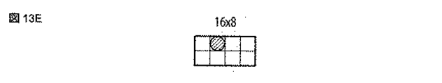
符号化対象プレディクションユニットのサイズが最小プレディクションユニットより大きい場合には、プレディクションユニット位置Colは、複数の参照動き情報166を時間方向参照動き情報メモリ502に保持している可能性がある。この場合、参照位置情報164に従って位置Colのプレディクションユニット中の参照動き情報166を取得する。以降、位置Colのプレディクションユニット中の参照動き情報166の取得位置を参照動き情報取得位置と称する。図13A〜Fは、参照位置情報164が位置Colのプレディクションユニットの中心を示す場合の参照動き情報取得位置の一例を符号化対象プレディクションユニットのサイズ(32x32〜16x16)毎に示す。図中のブロックはそれぞれ4x4プレディクションユニットを示し、丸印は予測動き情報候補951として取得する4x4プレディクションユニットの位置を示している。参照動き情報取得位置の別の一例を図14A〜Fに示す。図14A〜Fにおいて、丸印の位置は4x4プレディクションユニットが存在しないため、丸印に隣接する4つの4x4プレディクションユニットにおける参照動き情報166の平均値やメディアン値といった予め定められた方式で、予測動き情報候補951を生成する。参照動き情報取得位置の更に別の一例として、位置Colのプレディクションユニットの左上端に位置する4x4プレディクションユニットの参照動き情報166を予測動き情報候補951としても構わない。上記の例以外に置いても、予め定められた方式であれば、いずれの位置及び方式を用いて予測動き情報候補951を生成しても構わない。
When the size of the prediction unit to be encoded is larger than the minimum prediction unit, the prediction unit position Col may hold a plurality of reference motion information 166s in the time direction reference
なお、参照動き情報166が存在しない場合、ゼロベクトルを有する動き情報160を、予測動き情報候補951として出力する。
When the
以上により、少なくとも一つ以上の予測動き情報候補951が参照動きブロックから出力される。上記の予測動き情報候補951が有する参照フレーム番号と符号化対象プレディクションユニットの参照フレーム番号が異なる場合は、予測動き情報候補951を予測動き情報候補951が有する参照フレーム番号と符号化対象プレディクションユニットの参照フレーム番号に従ってスケーリングしても構わない。
As described above, at least one or more predicted
予測動き情報選択スイッチ902は、符号化制御部114からの指令に応じて複数の予測動き情報候補951から一つを選択し、予測動き情報952を出力する。また予測動き情報選択スイッチ902が、後述する予測動き情報位置情報954を出力してもよい。上記、選択には数式(1)や(2)といった評価関数を用いて選択しても構わない。減算部903は、動き情報160から予測動きベクトル情報952を減算し、差分動き情報953を差分動き情報符号化部904に出力する。差分動き情報符号化部904は、差分動き情報953を符号化処理し符号化データ960Aを出力する。なお、スキップモード及びマージモードでは差分動き情報符号化部904において、差分動き情報953の符号化は不要となる。
The predicted motion
予測動き情報位置符号化部905は、図12で示されるリストのうち、どの予測動き情報候補951を選択したかを示す予測動き情報位置情報954(Mvpidx)を符号化し、符号化データ960Bを出力する。予測動き情報位置情報954は予測動き情報候補951の総数から生成される等長符号化や可変長符号化を用いて符号化される。隣接ブロックとの相関を利用して可変長符号化しても構わない。更に、複数の予測動き情報候補951で重複する情報を有する場合、重複する予測動き情報候補951を削除した予測動き情報候補951の総数から符号表を作成し、予測動き情報位置情報954を符号化しても構わない。また、予測動き情報候補951の総数が1種類である場合、当該予測動き情報候補951が予測動き情報952と決定されるため、予測動き情報位置情報954を符号化する必要はない。
The predicted motion information
また、スキップモード、マージモード、インターモードそれぞれにおいて、予測動き情報候補951の導出方法は同一である必要はなく、それぞれ独立に予測動き情報候補951の導出方法を設定しても構わない。本実施形態では、スキップモードとインターモードの予測動き情報候補951の導出方法は同一で、マージモードの予測動き情報候補951の導出方法は異なるものとして説明する。
Further, the derivation method of the predicted
<動き情報圧縮部109の詳細>
まず、動き情報圧縮処理について図15を用いて説明する。図15は、空間方向参照動き情報メモリ501の参照動き情報166を圧縮し、時間方向参照動き情報メモリ502へ格納する。空間方向参照動き情報メモリ501では動き情報圧縮ブロック(同図では16x16画素ブロック)毎に代表動き情報位置に保持される参照動き情報166を時間方向参照動き情報メモリ502に格納する。上述の動き情報符号化処理を行う場合には、前述の参照動き情報取得位置に保持される参照動き情報166を予測動き情報候補951として設定する。このとき、仮想的に動き情報圧縮ブロック内は同一の参照動き情報166を持つこととして、前述の参照動き情報取得位置に保持される参照動き情報166を予測動き情報候補951として設定しても構わない(同一の予測動き情報候補951が導出される。)
次に、動き情報圧縮部109について図16に示すフローチャートを用いて説明する。動き情報圧縮部109は、フレーム(もしくはスライス、コーディングユニットなど任意の単位)の符号化処理が終了した際に、動き情報160を圧縮して時間方向参照動き情報メモリ502に動き情報160を格納する。
<Details of motion
First, the motion information compression process will be described with reference to FIG. In FIG. 15, the
Next, the motion
まず、符号化制御部114から参照位置情報164を取得し(ステップS1601)、フレームを動き情報160の圧縮単位である動き情報圧縮ブロックに分割する(ステップS1602)。動き情報圧縮ブロックは、動き補償処理により動き情報160が保持される単位(典型的には4x4画素ブロック)より大きい画素ブロックであり、典型的には16x16画素ブロックである。動き情報圧縮ブロックは64x64画素ブロックや32x32画素ブロック、8x8画素ブロック、長方形画素ブロック、任意の形状の画素領域であっても構わない。
First, the
次に、参照位置情報164に従って代表動き情報位置を生成する(ステップS1603)。代表動き情報位置を生成する一例として、動き情報圧縮ブロックが16x16画素ブロックの場合、図13D、図14D、図17Dにそれぞれ示されるプレディクションユニットのサイズが16x16の場合の参照動き情報取得位置を代表動き情報位置とする。次に、生成した代表動き情報位置の参照動き情報166を代表動き情報に設定し(ステップS1604)、当該代表動き情報を時間方向参照動き情報メモリに格納する(ステップS1605)。上記のステップS1604〜S1605をすべての動き情報圧縮ブロックに対して実行する。
Next, the representative motion information position is generated according to the reference position information 164 (step S1603). As an example of generating the representative motion information position, when the motion information compression block is a 16x16 pixel block, the reference motion information acquisition position when the size of the prediction unit shown in FIGS. 13D, 14D, and 17D is 16x16 is representative. It is the motion information position. Next, the
動き情報160が保持される単位をMxMブロック、動き情報圧縮ブロックのサイズをNxN(NはMの倍数)とすると、上記動き情報圧縮処理を実行することにより、参照動き情報メモリの容量を(MxM)/(NxN)に削減することが可能となる。
Assuming that the unit in which the
<代表動き情報位置の別の実施形態>
代表動き情報位置を生成する別の例として、複数の参照動き情報取得位置の中心位置を代表動き情報位置としても構わない。図18A及び図18Bはサイズが16x16である動き圧縮ブロック毎の代表動き情報位置を示している。図18Aは、参照動き情報取得位置が図13Dに示される位置である場合の代表動き情報位置、同様に図18Bは、参照動き情報取得位置が図17Dに示される位置である場合の代表動き情報位置をそれぞれ示している。図18A及び図18B中の丸印は、プレディクションユニットが16x16ブロックである際の、参照動き情報取得位置を示しており、4点の参照動き情報取得位置の中心位置(重心位置とも称す)にバツ印で示される代表動き情報位置を配置している。
<Another Embodiment of Representative Movement Information Position>
As another example of generating the representative motion information position, the center position of the plurality of reference motion information acquisition positions may be set as the representative motion information position. 18A and 18B show representative motion information positions for each motion compression block of size 16x16. FIG. 18A is a representative motion information position when the reference motion information acquisition position is the position shown in FIG. 13D, and FIG. 18B is similarly representative motion information when the reference motion information acquisition position is the position shown in FIG. 17D. Each position is shown. The circles in FIGS. 18A and 18B indicate the reference motion information acquisition positions when the prediction unit is a 16x16 block, and are located at the center positions (also referred to as the center of gravity positions) of the four reference motion information acquisition positions. The representative movement information position indicated by the cross mark is arranged.
代表動き情報位置を生成する更に別の例として、複数のプレディクションユニットのサイズ毎の参照動き情報取得位置を参照位置情報164として有し、複数の参照動き情報取得位置から代表動き情報位置を生成しても構わない。
As yet another example of generating the representative motion information position, the reference motion information acquisition position for each size of a plurality of prediction units is provided as the
代表動き情報位置を生成する一例として、複数のプレディクションユニットのサイズ毎の参照動き情報取得位置を参照位置情報164として有し、複数の参照動き情報取得位置から代表動き情報位置を生成しても構わない。図19は、ツリーブロックが64x64画素ブロックである場合の、プレディクションユニットのサイズが16x16以上の各サイズにおけるプレディクションユニットの中心(参照動き情報取得位置)をそれぞれ示している。
As an example of generating the representative motion information position, even if the reference motion information acquisition position for each size of a plurality of prediction units is provided as the
代表動き情報位置を生成する別の一例として、代表動き情報位置は動き情報圧縮ブロック毎に配置される参照動き情報取得位置を用いて設定されても構わない。図20Aは、動き情報圧縮ブロック毎の複数の参照動き情報取得位置の重心を代表動き情報位置と設定した場合の例を示す。重心位置が4x4ブロックの位置と一致しない場合には、最近傍の4x4ブロックを代表動き情報位置としてもよいし、共一次内挿法などの内挿法を用いて重心位置の参照動きベクトル166を生成しても構わない。
As another example of generating the representative motion information position, the representative motion information position may be set by using the reference motion information acquisition position arranged for each motion information compression block. FIG. 20A shows an example in which the center of gravity of a plurality of reference motion information acquisition positions for each motion information compression block is set as the representative motion information position. If the position of the center of gravity does not match the position of the 4x4 block, the nearest 4x4 block may be used as the representative motion information position, or the
また、図20Bは動き情報圧縮ブロック毎に複数の参照動き情報取得位置のいずれかを選択し、代表動き情報位置と設定した場合の例を示す。 Further, FIG. 20B shows an example in which one of a plurality of reference motion information acquisition positions is selected for each motion information compression block and set as a representative motion information position.
更に、図21A、図21Bにツリーブロック内で各動き情報圧縮ブロックで参照動き情報取得位置を同一にした場合の例を更に示す。全ての動き情報圧縮ブロック内で同一の代表動き情報位置であるため、ツリーブロック内の位置に応じて、代表動き情報位置を切り替える必要はない。また、代表動き情報位置は図21A、図21B以外にも、動き情報圧縮ブロック内の左上端や右上端など、いずれの位置にあっても構わない。 Further, FIGS. 21A and 21B further show an example in which the reference motion information acquisition position is the same in each motion information compression block in the tree block. Since the representative motion information position is the same in all the motion information compression blocks, it is not necessary to switch the representative motion information position according to the position in the tree block. In addition to FIGS. 21A and 21B, the representative motion information position may be at any position such as the upper left end or the upper right end in the motion information compression block.
代表動き情報位置を生成する一例、動き情報圧縮ブロック内の4x4ブロック位置をZスキャン順で示すBlkIdxを用いて代表動き情報位置を示しても構わない。動き情報圧縮ブロックのサイズが16x16である場合に、図21Aに示される代表動き情報位置はBlkIdx=12の位置に相当する。また、図21Bに示される代表動き情報位置はBlkIdx=15の位置に相当する。 As an example of generating the representative motion information position, the representative motion information position may be indicated by using BlkIdx which indicates the 4x4 block position in the motion information compression block in the Z scan order. When the size of the motion information compression block is 16x16, the representative motion information position shown in FIG. 21A corresponds to the position of BlkIdx = 12. The representative motion information position shown in FIG. 21B corresponds to the position of BlkIdx = 15.
動き情報圧縮処理における別の一例として、参照フレーム番号に関するメモリ容量を削減するために、動き情報圧縮処理に参照フレーム番号を含めても構わない。この場合、代表動き情報位置に保持される参照フレーム番号を参照フレーム番号に関するメモリ容量に格納する。従って、図5に示される空間方向参照動き情報メモリ501及び空間方向参照動き情報メモリ502は動きベクトル情報に追加して参照フレーム番号を格納する。
As another example in the motion information compression process, the reference frame number may be included in the motion information compression process in order to reduce the memory capacity related to the reference frame number. In this case, the reference frame number held at the representative motion information position is stored in the memory capacity related to the reference frame number. Therefore, the spatial reference
動き情報圧縮処理における更に別の一例として、動き情報圧縮処理に参照フレーム番号を含めない場合に、代表動き情報位置にある動き情報内の動きベクトル情報を、参照フレーム番号を用いてスケーリング処理を施して、動き情報メモリ110に格納しても構わない。スケーリング処理の典型例として、参照フレーム番号ゼロを基準とした線形スケーリング処理がある。これは、参照フレーム番号がゼロ以外の値である場合に、動きベクトル情報が参照フレーム番号ゼロに対応する参照フレームを参照するように線形スケーリング処理するものである。上述のスケーリング処理の基準は参照フレーム番号がゼロ以外の値であっても構わない。上述の線形スケーリング処理を行う場合に除算が発生する場合には、予め除算処理をテーブル化しておき、都度テーブルを引くことで上記除算を実現しても構わない。
As yet another example of the motion information compression process, when the reference frame number is not included in the motion information compression process, the motion vector information in the motion information at the representative motion information position is scaled using the reference frame number. It may be stored in the
動き情報圧縮ブロックのサイズが16x16ブロック以外の場合、上述と同様の処理を用いて代表動き情報位置を生成する。一例では、動き情報圧縮ブロックのサイズが64x64の場合、プレディクションユニットのサイズが64x64における参照動き情報取得位置を代表動き情報位置とする。更に別の一例では、図21A、図21B等で示される動き情報圧縮ブロックのサイズが16x16ブロックにおける代表動き情報位置を、動き情報圧縮ブロックのサイズに従って水平方向及び垂直方向でスケーリングした位置を代表動き情報位置としても構わない。 When the size of the motion information compression block is other than 16x16 blocks, the representative motion information position is generated by using the same processing as described above. In one example, when the size of the motion information compression block is 64x64, the reference motion information acquisition position when the size of the prediction unit is 64x64 is set as the representative motion information position. In yet another example, the representative motion information position when the size of the motion information compression block shown in FIGS. 21A and 21B is 16x16 blocks is scaled in the horizontal and vertical directions according to the size of the motion information compression block. It may be the information position.
代表動き情報位置が、ピクチャやスライスの外であるとして参照動き情報が存在しない場合には、動き情報圧縮ブロックの左上端といった動き情報圧縮ブロック内で参照動き情報が取得可能な位置を新しい代表動き情報位置として置き換えても構わない。また、代表動き情報位置が、イントラ予測が適用された領域であって、参照動き情報が存在しない場合にも同様の処理を実行して、新しい代表動き情報位置として置き換えても構わない。 If the reference motion information does not exist because the representative motion information position is outside the picture or slice, the new representative motion is the position where the reference motion information can be obtained in the motion information compression block such as the upper left corner of the motion information compression block. It may be replaced as an information position. Further, even when the representative motion information position is the area to which the intra prediction is applied and the reference motion information does not exist, the same process may be executed to replace it as a new representative motion information position.
<シンタクス構成>
以下、図1の画像符号化装置100が利用するシンタクスについて説明する。
シンタクスは、画像符号化装置が動画像データを符号化する際の符号化データ(例えば、図1の符号化データ163)の構造を示している。この符号化データを復号化する際に、同じシンタクス構造を参照して動画像復号化装置がシンタクス解釈を行う。図1の動画像符号化装置が利用するシンタクス2200を図22に例示する。
<Syntax configuration>
Hereinafter, the syntax used by the
The syntax shows the structure of the coded data (for example, the coded
シンタクス2200は、ハイレベルシンタクス2201、スライスレベルシンタクス2202及びコーディングツリーレベルシンタクス2203の3つのパートを含む。ハイレベルシンタクス2201は、スライスよりも上位のレイヤのシンタクス情報を含む。スライスとは、フレームまたはフィールドに含まれる矩形領域もしくは連続領域を指す。スライスレベルシンタクス2202は、各スライスを復号化するために必要な情報を含む。コーディングツリーレベルシンタクス2203は、各コーディングツリー(即ち、各コーディングツリーユニット)を復号化するために必要な情報を含む。これら各パートは、さらに詳細なシンタクスを含む。
The
ハイレベルシンタクス2201は、シーケンスパラメータセットシンタクス2204及びピクチャパラメータセットシンタクス2205などの、シーケンス及びピクチャレベルのシンタクスを含む。スライスレベルシンタクス2202は、スライスヘッダーシンタクス2206及びスライスデータシンタクス2207などを含む。コーディングツリーレベルシンタクス2203は、コーディングツリーユニットシンタクス2208、トランスフォームユニットシンタクス2209及びプレディクションユニットシンタクス2210などを含む。
High-
コーディングツリーユニットシンタクス2208は、四分木構造を持つことができる。具体的には、コーディングツリーユニットシンタクス2208のシンタクス要素として、さらにコーディングツリーユニットシンタクス2208を再帰呼び出しすることができる。即ち、1つのコーディングツリーユニットを四分木で細分化することができる。また、コーディングツリーユニットシンタクス2208内にはトランスフォームユニットシンタクス2209及びプレディクッションユニットシンタクス2210が含まれている。トランスフォームユニットシンタクス2209及びプレディクッションユニットシンタクス2210は、四分木の最末端の各コーディングツリーユニットシンタクス2208において呼び出される。プレディクッションユニットシンタクス2210は予測に関わる情報、トランスフォームユニットシンタクス2209は、逆直交変換及び量子化などに関わる情報がそれぞれ記述されている。 The coding tree unit Syntax 2208 can have a quadtree structure. Specifically, the coding tree unit syntax 2208 can be recursively called as a syntax element of the coding tree unit syntax 2208. That is, one coding tree unit can be subdivided into quadtrees. Further, the coding tree unit syntax 2208 includes a transform unit syntax 2209 and a predi cushion unit syntax 2210. The transform unit syntax 2209 and the predi cushion unit syntax 2210 are called in each coding tree unit syntax 2208 at the end of the quadtree. The pre-cushion unit syntax 2210 describes information related to prediction, and the transform unit syntax 2209 describes information related to inverse orthogonal transformation and quantization.
図23は、本実施形態に係るシーケンスパラメータセットシンタクス2204を例示する。図23A及び図23Bに示されるmotion_vector_buffer_comp_flagは、当該シーケンスに関して本実施形態に係る動き情報圧縮の有効/無効を示すシンタクスである。motion_vector_buffer_comp_flagが0である場合、当該シーケンスに関して本実施形態に係る動き情報圧縮は無効である。従って、図1に示される動き情報圧縮部の処理はスキップされる。一例として、motion_vector_buffer_comp_flagが1である場合、当該シーケンスに関して本実施携帯に係る動き情報圧縮は有効である。図23及び図23Bに示されるmotion_vector_buffer_comp_ratio_log2は、動き情報圧縮処理の単位を示す情報であり、motion_vector_buffer_comp_flagが1である場合に示される。motion_vector_buffer_comp_ratio_log2は、例えば本実施形態に係る動き情報圧縮ブロックのサイズの情報を示し、motion_vector_buffer_comp_ratio_log2は、動き補償の最小単位に2(motion_vector_buffer_comp_ratio_log2)を乗じた値が動き情報圧縮ブロックのサイズとなる。動き補償の最小単位が4x4画素ブロックである、つまり参照動き情報メモリが4x4画素ブロック単位に保持される場合の例を以下に示す。motion_vector_buffer_comp_ratio_log2が1の場合、本実施形態に係る動き情報圧縮ブロックのサイズは8x8画素ブロックとなる。同様に、motion_vector_buffer_comp_ratio_log2が2の場合、本実施形態に係る動き情報圧縮ブロックのサイズは16x16画素ブロックとなる。図23Bに示されるmotion_vector_buffer_comp_positionは、動き情報圧縮ブロック内の代表動き情報位置を示す情報であり、motion_vector_buffer_comp_flagが1である場合に示される。motion_vector_buffer_comp_positionは、例えば図21A、図21Bに示されるような動き情報圧縮ブロック内の参照動き情報位置を示したり、図20A、図20Bに示されるように動き情報圧縮ブロック毎の参照動き情報位置を示しても構わない。また、複数のブロックの中心にあっても構わない。 FIG. 23 illustrates the sequence parameter set syntax 2204 according to this embodiment. The motion_vector_buffer_comp_flag shown in FIGS. 23A and 23B is a syntax indicating the validity / invalidity of the motion information compression according to the present embodiment with respect to the sequence. When motion_vector_buffer_comp_flag is 0, the motion information compression according to the present embodiment is invalid for the sequence. Therefore, the processing of the motion information compression unit shown in FIG. 1 is skipped. As an example, when motion_vector_buffer_comp_flag is 1, the motion information compression related to the present mobile phone is effective for the sequence. The motion_vector_buffer_comp_ratio_log2 shown in FIGS. 23 and 23B is information indicating a unit of motion information compression processing, and is shown when the motion_vector_buffer_comp_flag is 1. The motion_vector_buffer_comp_ratio_log2 indicates, for example, the size information of the motion information compression block according to the present embodiment, and the motion_vector_buffer_comp_ratio_log2 is the minimum unit of motion compensation, and the motion compensation is 2 (motion_vector_buffer_buffer) . An example in which the minimum unit of motion compensation is a 4x4 pixel block, that is, the reference motion information memory is held in the 4x4 pixel block unit is shown below. When motion_vector_buffer_comp_ratio_log2 is 1, the size of the motion information compression block according to the present embodiment is an 8x8 pixel block. Similarly, when motion_vector_buffer_comp_ratio_log2 is 2, the size of the motion information compression block according to the present embodiment is a 16x16 pixel block. The motion_vector_buffer_comp_position shown in FIG. 23B is information indicating a representative motion information position in the motion information compression block, and is shown when the motion_vector_buffer_comp_flag is 1. The motion_vector_buffer_comp_position indicates, for example, the reference motion information position in the motion information compression block as shown in FIGS. 21A and 21B, and indicates the reference motion information position for each motion information compression block as shown in FIGS. 20A and 20B. It doesn't matter. It may also be in the center of a plurality of blocks.
また、別の例として、motion_vector_buffer_comp_flag、motion_vector_buffer_comp_ratio_log2、motion_vector_buffer_comp_positionより下位のレイヤ(ピクチャパラメータセットシンタクス、スライスレベルシンタクス、コーディングツリーユニット、トランスフォームユニットなど)のシンタクスにおいて当該スライス内部の局所領域毎に本実施形態に係る予測の有効/無効が規定されてもよい。 As another example, the layers below the prediction_vector_buffer_comp_flag, the motion_vector_buffer_comp_ratio_log2, the motion_vector_buffer_comp_position, etc. The validity / invalidity of such prediction may be specified.
図24に、プレディクションユニットシンタクスの一例を示す。図中のskip_flagは、プレディクションユニットシンタクスが属するコーディングユニットの予測モードがスキップモードであるか否かを示すフラグである。skip_flagが1である場合、予測動き情報位置情報954以外のシンタクス(コーディングユニットシンタクス、プレディクションユニットシンタクス、トランスフォームユニットシンタクス)を符号化しないことを示す。NumMVPCand(L0)、NumMVPCand(L1)は、それぞれリスト0予測、リスト1予測における予測動き情報候補951の数を示す。予測動き情報候補951が存在する(NumMVPCand(LX)>0、X=0若しくは1)場合、予測動き情報位置情報954を示すmvp_idx_lXが符号化される。
FIG. 24 shows an example of the prediction unit syntax. Skip_flag in the figure is a flag indicating whether or not the prediction mode of the coding unit to which the prediction unit syntax belongs is the skip mode. When skip_flag is 1, it means that the syntaxes other than the predicted motion information position information 954 (coding unit syntax, prediction unit syntax, transform unit syntax) are not encoded. NumMVPCand (L0) and NumMVPCand (L1) indicate the number of predicted
skip_flagが0である場合、プレディクションユニットシンタクスが属するコーディングユニットの予測モードがスキップモードではないことを示す。NumMergeCandidatesは、図12などで導出される予測動き情報候補951の数を示す。予測動き情報候補951が存在する(NumMergeCandidates>0)場合、プレディクションユニットがマージモードであるか否かを示すフラグであるmerge_flagが符号化される。merge_flagは、その値が1である場合、プレディクションユニットがマージモードであることを示し、その値が0である場合、プレディクションユニットがインターモードを用いることを示す。merge_flagが1且つ予測動き情報候補951が2つ以上存在する(NumMergeCandidates>1)場合、予測動き情報候補951の内、どのブロックからマージするかを示す予測動き情報952であるmerge_idxが符号化される。
When skip_flag is 0, it indicates that the prediction mode of the coding unit to which the prediction unit syntax belongs is not the skip mode. NumberCandidates shows the number of predicted
merge_flagが1である場合、merge_flag、merge_idx以外のプレディクションユニットシンタクスは符号化する必要はない。 When the message_flag is 1, the prediction unit syntax other than the message_flag and the message_idx does not need to be encoded.
merge_flagが0である場合、プレディクションユニットがインターモードであることを示す。インターモードでは差分動き情報953が含む差分動きベクトル情報を示すmvd_lX(X=0若しくは1)や参照フレーム番号ref_idx_lX、Bスライスの場合、プレディクションユニットが単方向予測(リスト0若しくはリスト1)であるか双方向予測であるかを示すinter_pred_idcが符号化される。また、スキップモードと同様にNumMVPCand(L0)、NumMVPCand(L1)を取得し、予測動き情報候補951が存在する(NumMVPCand(LX)>0、X=0若しくは1)場合、予測動き情報位置情報954を示すmvp_idx_lXが符号化される。
When merge_flag is 0, it indicates that the prediction unit is in intermode. In the intermode, in the case of mvd_lX (X = 0 or 1) indicating the differential motion vector information included in the
以上が、本実施形態に係るシンタクス構成である。 The above is the syntax configuration according to this embodiment.
(第2の実施形態)
第2の実施形態は動画像復号化装置に関する。本実施形態に係る動画像復号化装置に対応する動画像符号化装置は、第1の実施形態において説明した通りである。即ち、本実施形態に係る動画像復号化装置は、例えば第1の実施形態に係る動画像符号化装置によって生成された符号化データを復号化する。
(Second Embodiment)
The second embodiment relates to a moving image decoding device. The moving image coding device corresponding to the moving image decoding device according to the present embodiment is as described in the first embodiment. That is, the moving image decoding device according to the present embodiment decodes the coded data generated by the moving image coding device according to the first embodiment, for example.
図25に示すように、本実施形態に係る動画像復号化装置は、エントロピー復号化部2501、逆量子化部2502、逆直交変換部2503、加算部2504、参照画像メモリ2505、インター予測部2506、参照動き情報メモリ2507、参照動き情報圧縮部2508及び復号化制御部2510を含む。
As shown in FIG. 25, the moving image decoding apparatus according to the present embodiment includes an
図25の動画像復号化装置は、符号化データ2550を復号し、復号画像信号2554を出力バッファ2511に蓄積して出力画像として出力する。符号化データ2550は、例えば図1の動画像符号化装置などから出力され、図示しない蓄積系または伝送系を経て、動画像復号化装置2500に入力される。
The moving image decoding device of FIG. 25 decodes the coded
エントロピー復号化部2501は、符号化データ2550の復号化のために、シンタクスに基づいて解読を行う。エントロピー復号化部2501は、各シンタクスの符号列を順次エントロピー復号化し、動き情報2559、量子化変換係数2551などの符号化対象ブロックの符号化パラメータを再生する。符号化パラメータとは、予測情報、変換係数に関する情報、量子化に関する情報、などの復号に必要となるパラメータである。
The
具体的には、エントロピー復号化部2501は、図26に示すように、分離部2601、パラメータ復号化部2602、変換係数復号化部2603、並びに動き情報復号化部2604を備える。分離部2601は符号化データ2550を分離し、パラメータに関する符号化データ2651Aをパラメータ復号化部2602、変換係数に関する符号化データ2651Bを変換係数復号化部2603、動き情報に関する符号化データ2651Cを動き情報復号化部2604にそれぞれ出力する。パラメータ復号化部2602は、予測情報などの符号化パラメータ2570を復号化し符号化パラメータ2570を出力し復号化制御部2510に出力する。変換係数復号化部2603は、符号化データ2651Bを入力し、変換係数情報2551を復号化して逆量子化部2502に出力する。
Specifically, as shown in FIG. 26, the
動き情報復号化部2604は、分離部2601から符号化データ2651C、復号化制御部2510から参照位置情報2560、参照動き情報メモリ2507から参照動き情報2558をそれぞれ受け取り、動き情報2559を出力する。出力された動き情報2559はインター予測部2506に入力される。
The motion
動き情報復号化部2604は、図27に示すように、分離部2701、差分動き情報復号化部2702、予測動き情報位置復号化部2503、参照動き情報取得部2704、予測動き情報選択スイッチ2705及び加算部2706を含む。
As shown in FIG. 27, the motion
動き情報に関する符号化データ2651Cを分離部2701に入力し、差分動き情報に関する符号化データ2751と予測動き情報位置に関する符号化データ2752に分離する。差分動き情報符号化部2702は、差分動き情報に関する符号化データ2751を入力し、差分動き情報2753を復号化する。差分動き情報2753は加算部2706にて後述する予測動き情報2756と加算され、動き情報2759が出力される。予測動き情報位置復号化部2703は予測動き情報位置に関する符号化データ2752を入力し、予測動き情報位置2754を復号化する。
The coded
予測動き情報位置2754は予測動き情報選択スイッチ2705に入力され、予測動き情報候補2755の中から予測動き情報2756を選択する。予測動き情報位置情報2560は予測動き情報候補2755の数から生成される等長復号化や可変長復号化を用いて復号化される。隣接ブロックとの相関を利用して可変長復号化しても構わない。更に、複数の予測動き情報候補2755で重複する場合、重複を削除した予測動き情報候補2755の総数から生成される符号表から、予測動き情報位置情報2560を復号化しても構わない。また、予測動き情報候補2755の総数が1種類である場合、当該予測動き情報候補2755が予測動き情報2556と決定されるため、予測動き情報位置情報2754を復号化する必要はない。
The predicted
参照動き情報取得部2704は第1の実施形態で説明した参照動き情報取得部901とその構成、処理内容は同一である。
The reference motion
参照動き情報取得部2704は、参照動き情報2558及び参照位置情報2560を入力として、少なくとも一つ以上の予測動き情報候補2755(2755A、2755B、…)を生成する。図10、図11は、復号化対象プレディクションユニットに対する、予測動き情報候補2755の位置の一例を示している。図10は復号化対象プレディクションユニットに空間的に隣接するプレディクションユニットの位置を示している。AX(X=0〜nA−1)は、対象プレディクションユニットに対して左に隣接するプレディクションユニット、BY(Y=0〜nB−1)は対象プレディクションユニットに対して上に隣接するプレディクションユニット、C、D、Eは復号化対象プレディクションユニットに対してそれぞれ右上、左上、左下に隣接するプレディクションユニットを示している。また、図11は復号化対象プレディクションユニットに対して、既に復号化済みの参照フレームにおけるプレディクションユニットの位置を示している。図中のColは、参照フレーム内であって復号化対象プレディクションユニットと同一位置にあるプレディクションユニットを示している。図12は、複数の予測動き情報候補2755のブロック位置とインデクスMvpidxの関係を示すリストの一例を示す。Mvpidxが0〜2は空間方向に位置する予測動き情報候補2755、Mvpidxが3は時間方向に位置する測動きベクトル候補2755をそれぞれ示している。プレディクションユニット位置Aは図10に示されるAXの内、インター予測である、つまり参照動き情報2558を有するプレディクションユニットであって、Xの値が最も小さい位置をプレディクションユニット位置Aとする。また、プレディクションユニット位置Bは図10に示されるBYの内、インター予測である、つまり参照動き情報2558を有するプレディクションユニットであって、Yの値が最も小さい位置をプレディクションユニット位置Aとする。プレディクションユニット位置Cがインター予測ではない場合、プレディクションユニット位置Dの参照動き情報2558をプレディクションユニット位置Cの参照動き情報2558として置き換える。プレディクションユニット位置C及びDがインター予測ではない場合、プレディクションユニット位置Eの参照動き情報2558をプレディクションユニット位置Cの参照動き情報2558として置き換える。
The reference motion
復号化対象プレディクションユニットのサイズが最小プレディクションユニットより大きい場合には、プレディクションユニット位置Colは、複数の参照動き情報2558を時間方向参照動き情報メモリ2507に保持している可能性がある。この場合、参照位置情報2560に従って位置Colのプレディクションユニット中の参照動き情報2558を取得する。以降、位置Colのプレディクションユニット中の参照動き情報2558の取得位置を参照動き情報取得位置と称する。図13A〜Fは、参照位置情報2560が位置Colのプレディクションユニットの中心を示す場合の参照動き情報取得位置の一例を復号化対象プレディクションユニットのサイズ(32x32〜16x16)毎に示す。図中のブロックはそれぞれ4x4プレディクションユニットを示し、丸印は予測動き情報候補2755として取得する4x4プレディクションユニットの位置を示している。参照動き情報取得位置の別の一例を図14A〜Fに示す。図14A〜Fにおいて、丸印の位置は4x4プレディクションユニットが存在しないため、丸印に隣接する4つのx4プレディクションユニットにおける参照動き情報2558の平均値やメディアン値といった予め定められた方式で、予測動き情報候補2755を生成する。参照動き情報取得位置の更に別の一例として、位置Colのプレディクションユニットの左上端に位置する4x4プレディクションユニットの参照動き情報2558を予測動き情報候補2755としても構わない。上記の例以外に置いても、予め定められた方式であれば、いずれの位置及び方式を用いて予測動き情報候補2755を生成しても構わない。
When the size of the prediction unit to be decoded is larger than the minimum prediction unit, the prediction unit position Col may hold a plurality of
なお、参照動き情報2558が存在しない場合、ゼロベクトルを有する動き情報2559を、予測動き情報候補2755として出力する。
If the
以上により、少なくとも一つ以上の予測動き情報候補2755が参照動きブロックから出力される。上記の予測動き情報候補2755が有する参照フレーム番号と復号化対象プレディクションユニットの参照フレーム番号が異なる場合、予測動き情報候補2755を予測動き情報候補2755が有する参照フレーム番号と復号化対象プレディクションユニットの参照フレーム番号に従ってスケーリングしても構わない。予測動き情報選択スイッチ2705は、複数の予測動き情報候補2755から予測動き情報位置2754に従って一つを選択し、予測動き情報952を出力する。
As described above, at least one or more predicted
逆量子化部2502は、エントロピー復号化部2501からの量子化変換係数2551に逆量子化を行って、復元変換係数2552を得る。具体的には、逆量子化部2502は、エントロピー復号化部2501によって復号化された量子化に関する情報に従って逆量子化を行う。逆量子化部2502は、復元変換係数2552を逆直交変換部2503に出力する。
The
逆直交変換部2503は、逆量子化部2502からの復元変換係数2552に対して、符号化側において行われた直交変換に対応する逆直交変換を行い、復元予測誤差信号2553を得る。逆直交変換部2503は、復元予測誤差信号2553を加算部2504に入力する。
The inverse
加算部2504は、復元予測誤差信号2553と、対応する予測画像信号2556とを加算し、復号画像信号2554を生成する。復号画像信号2554は、図示されないデブロッキングフィルタやウィナーフィルタなどを施し、出力画像のために出力バッファ2511に一時的に蓄積されると共に、参照画像信号2555のために参照画像メモリ2505にも保存される。参照画像メモリ2505に保存された復号画像信号2554は、参照画像信号2555としインター予測部2506によって必要に応じてフレーム単位またはフィールド単位で参照される。出力バッファ2511に一時的に蓄積された復号画像信号2554は、復号化制御部2510によって管理される出力タイミングに従って出力される。
The
インター予測部2506は、参照画像メモリ2505に保存されている参照画像信号2555を利用してインター予測を行う。具体的には、インター予測部2506は、予測対象ブロックと参照画像信号2555との間の動きのズレ量(動きベクトル)を含む動き情報2559をエントロピー復号化部2501から取得し、この動きベクトルに基づいて補間処理(動き補償)を行ってインター予測画像を生成する。インター予測画像の生成に関しては、第一の実施形態と同一であるので、説明を省略する。
The
復号化制御部2510は、図25の動画像復号化装置の各要素を制御する。具体的には、復号化制御部2510は、後述する参照位置情報2560をエントロピー復号化部2501に出力したり、上述の動作を含む復号化処理のための種々の制御を行う。
The
<スキップモード、マージモード、インターモードの説明>
本実施形態に係る画像復号化装置2500は、図8に示す復号化処理の異なる複数の予測モードを使用する。図中のスキップモードは後述する予測動き情報位置2754に関するシンタクスのみを復号化し、その他のシンタクスは復号化しないモードである。マージモードは予測動き情報位置2754に関するシンタクス、変換係数情報2551のみを復号化し、その他のシンタクスは復号化しないモードである。インターモードは、予測動き情報位置2754に関するシンタクス、後述する差分動き情報2753、変換係数情報2551を復号化するモードである。これらのモードは復号化制御部2510が制御する予測情報2571によって切り替えられる。
<Explanation of skip mode, merge mode, and intermode>
The
また、図25の動画像復号化装置は、図28説明したシンタクスと同一または類似のシンタクスを利用するのでその詳細な説明を省略する。 Further, since the moving image decoding apparatus of FIG. 25 uses the same or similar syntax as the syntax described in FIG. 28, detailed description thereof will be omitted.
<動き情報圧縮部2508の詳細>
次に、動き情報圧縮部2508について図16に示すフローチャートを用いて説明する。動き情報圧縮部2508は、フレーム(もしくはスライス、コーディングユニットなど任意の単位)の復号化処理が終了した際に、動き情報2559を圧縮して時間方向参照動き情報メモリ502に動き情報2559を格納する。
<Details of motion
Next, the motion
まず、復号化制御部2510から参照位置情報2560を取得し(ステップS1601)、フレームを動き情報2559の圧縮単位である動き情報圧縮ブロックに分割する(ステップS1602)。動き情報圧縮ブロックは、動き補償処理により動き情報2559が保持される単位(典型的には4x4画素ブロック)より大きい画素ブロックであり、典型的には16x16画素ブロックである。動き情報圧縮ブロックは32x32画素ブロックや8x8画素ブロック、長方形画素ブロック、任意の形状の画素領域であっても構わない。
First, the
次に、参照位置情報2560に従って代表動き情報位置を生成する(ステップS1603)。代表動き情報位置を生成する一例として、動き情報圧縮ブロックが16x16画素ブロックの場合、図13D、図14D、図17Dにそれぞれ示されるプレディクションユニットのサイズが16x16の場合の参照動き情報取得位置を代表動き情報位置とする。次に、生成した代表動き情報位置の参照動き情報2558を代表動き情報に設定し(ステップS1605)、当該代表動き情報を時間方向参照動き情報メモリに格納する(ステップS1606)。上記のステップS1604〜S1605をすべての動き情報圧縮ブロックに対して実行する。
Next, the representative motion information position is generated according to the reference position information 2560 (step S1603). As an example of generating the representative motion information position, when the motion information compression block is a 16x16 pixel block, the reference motion information acquisition position when the size of the prediction unit shown in FIGS. 13D, 14D, and 17D is 16x16 is representative. It is the motion information position. Next, the generated
動き情報2559が保持される単位をMxMブロック、動き情報圧縮ブロックのサイズをNxN(NはMの倍数)とすると、上記動き情報圧縮処理を実行することにより、参照動き情報メモリの容量を(MxM)/(NxN)に削減することが可能となる。
Assuming that the unit in which the
<代表動き情報位置の別の実施形態>
代表動き情報位置を生成する別の例として、複数の参照動き情報取得位置の中心位置を代表動き情報位置としても構わない。図18A及び図18Bはサイズが16x16である動き圧縮ブロック毎の代表動き情報位置を示している。図18Aは、参照動き情報取得位置が図13Dに示される位置である場合の代表動き情報位置、同様に図18Bは、参照動き情報取得位置が図17Dに示される位置である場合の代表動き情報位置をそれぞれ示している。図18A及び図18B中の丸印は、プレディクションユニットが16x16である際の、参照動き情報取得位置を示しており、4点の参照動き情報取得位置の中心位置にバツ印で示される代表動き情報位置を配置している。
<Another Embodiment of Representative Movement Information Position>
As another example of generating the representative motion information position, the center position of the plurality of reference motion information acquisition positions may be set as the representative motion information position. 18A and 18B show representative motion information positions for each motion compression block of size 16x16. FIG. 18A is a representative motion information position when the reference motion information acquisition position is the position shown in FIG. 13D, and FIG. 18B is similarly representative motion information when the reference motion information acquisition position is the position shown in FIG. 17D. Each position is shown. The circles in FIGS. 18A and 18B indicate the reference motion information acquisition positions when the prediction unit is 16x16, and the representative motions indicated by cross marks at the center positions of the four reference motion information acquisition positions. The information position is arranged.
代表動き情報位置を生成する更に別の例として、複数のプレディクションユニットのサイズ毎の参照動き情報取得位置を参照位置情報2560として有し、複数の参照動き情報取得位置から代表動き情報位置を生成しても構わない。図19は、ツリーブロックが64x64画素ブロックである場合の、プレディクションユニットのサイズが16x16以上の各サイズにおけるプレディクションユニットの中心(参照動き情報取得位置)をそれぞれ示している。
As yet another example of generating the representative motion information position, the reference motion information acquisition position for each size of a plurality of prediction units is provided as the
代表動き情報位置を生成する別の一例として、代表動き情報位置は動き情報圧縮ブロック毎に配置される参照動き情報取得位置を用いて設定されても構わない。図20Aは、動き情報圧縮ブロック毎の複数の参照動き情報取得位置の重心を代表動き情報位置と設定した場合の例を示す。重心位置が4x4ブロックの位置と一致しない場合には、最近傍の4x4ブロックを代表動き情報位置としてもよいし、共一次内挿法などの内挿法を用いて重心位置の参照動きベクトル166を生成しても構わない。
As another example of generating the representative motion information position, the representative motion information position may be set by using the reference motion information acquisition position arranged for each motion information compression block. FIG. 20A shows an example in which the center of gravity of a plurality of reference motion information acquisition positions for each motion information compression block is set as the representative motion information position. If the position of the center of gravity does not match the position of the 4x4 block, the nearest 4x4 block may be used as the representative motion information position, or the
また、図20Bは動き情報圧縮ブロック毎に複数の参照動き情報取得位置のいずれかを選択し、代表動き情報位置と設定した場合の例を示す。 Further, FIG. 20B shows an example in which one of a plurality of reference motion information acquisition positions is selected for each motion information compression block and set as a representative motion information position.
更に、図21A、Bにツリーブロック内で各動き情報圧縮ブロックで参照動き情報取得位置を同一にした場合の例を更に示す。全ての動き情報圧縮ブロック内で同一の代表動き情報位置であるため、ツリーブロック内の位置に応じて、代表動き情報位置を切り替える必要はない。また、代表動き情報位置は図21A、B以外にも、動き情報圧縮ブロック内の左上端や右上端等いずれの位置にあっても構わない。 Further, FIGS. 21A and 21B further show an example in which the reference motion information acquisition position is the same in each motion information compression block in the tree block. Since the representative motion information position is the same in all the motion information compression blocks, it is not necessary to switch the representative motion information position according to the position in the tree block. Further, the representative motion information position may be at any position such as the upper left end or the upper right end in the motion information compression block other than FIGS. 21A and 21B.
代表動き情報位置を生成する一例、動き情報圧縮ブロック内の4x4ブロック位置をZスキャン順で示すBlkIdxを用いて代表動き情報位置を示しても構わない。動き情報圧縮ブロックのサイズが16x16である場合に、図21Aに示される代表動き情報位置はBlkIdx=12の位置に相当する。また、図21Bに示される代表動き情報位置はBlkIdx=15の位置に相当する。 As an example of generating the representative motion information position, the representative motion information position may be indicated by using BlkIdx which indicates the 4x4 block position in the motion information compression block in the Z scan order. When the size of the motion information compression block is 16x16, the representative motion information position shown in FIG. 21A corresponds to the position of BlkIdx = 12. The representative motion information position shown in FIG. 21B corresponds to the position of BlkIdx = 15.
動き情報圧縮処理における別の一例として、参照フレーム番号に関するメモリ容量を削減するために、動き情報圧縮処理に参照フレーム番号を含めても構わない。この場合、代表動き情報位置に保持される参照フレーム番号を参照フレーム番号に関するメモリ容量に格納する。従って、図5に示される空間方向参照動き情報メモリ501及び空間方向参照動き情報メモリ502は動きベクトル情報に追加して参照フレーム番号を格納する。
As another example in the motion information compression process, the reference frame number may be included in the motion information compression process in order to reduce the memory capacity related to the reference frame number. In this case, the reference frame number held at the representative motion information position is stored in the memory capacity related to the reference frame number. Therefore, the spatial reference
動き情報圧縮処理における更に別の一例として、動き情報圧縮処理に参照フレーム番号を含めない場合に、代表動き情報位置にある動き情報内の動きベクトル情報を、参照フレーム番号を用いてスケーリング処理を施して、動き情報メモリ110に格納しても構わない。スケーリング処理の典型例として、参照フレーム番号ゼロを基準とした線形スケーリング処理がある。これは、参照フレーム番号がゼロ以外の値である場合に、動きベクトル情報が参照フレーム番号ゼロに対応する参照フレームを参照するように線形スケーリング処理するものである。上述のスケーリング処理の基準は参照フレーム番号がゼロ以外の値であっても構わない。上述の線形スケーリング処理を行う場合に除算が発生する場合には、予め除算処理をテーブル化しておき、都度テーブルを引くことで上記除算を実現しても構わない。
As yet another example of the motion information compression process, when the reference frame number is not included in the motion information compression process, the motion vector information in the motion information at the representative motion information position is scaled using the reference frame number. It may be stored in the
動き情報圧縮ブロックのサイズが16x16ブロック以外の場合、上述と同様の処理を用いて代表動き情報位置を生成する。一例では、動き情報圧縮ブロックのサイズが64x64の場合、プレディクションユニットのサイズが64x64における参照動き情報取得位置を代表動き情報位置とする。更に別の一例では、図21A、図21B等で示される動き情報圧縮ブロックのサイズが16x16ブロックにおける代表動き情報位置を、動き情報圧縮ブロックのサイズに従って水平方向及び垂直方向でスケーリングした位置を代表動き情報位置としても構わない。 When the size of the motion information compression block is other than 16x16 blocks, the representative motion information position is generated by using the same processing as described above. In one example, when the size of the motion information compression block is 64x64, the reference motion information acquisition position when the size of the prediction unit is 64x64 is set as the representative motion information position. In yet another example, the representative motion information position when the size of the motion information compression block shown in FIGS. 21A and 21B is 16x16 blocks is scaled in the horizontal and vertical directions according to the size of the motion information compression block. It may be the information position.
代表動き情報位置が、ピクチャやスライスの外であるとして参照動き情報が存在しない場合には、動き情報圧縮ブロックの左上端といった動き情報圧縮ブロック内で参照動き情報が取得可能な位置を新しい代表動き情報位置として置き換えても構わない。また、代表動き情報位置がイントラ予測が適用された領域であって、参照動き情報が存在しない場合にも同様の処理を実行して、新しい代表動き情報位置として置き換えても構わない。 If the reference motion information does not exist because the representative motion information position is outside the picture or slice, the new representative motion is the position where the reference motion information can be obtained in the motion information compression block such as the upper left corner of the motion information compression block. It may be replaced as an information position. Further, even when the representative motion information position is the area to which the intra prediction is applied and the reference motion information does not exist, the same process may be executed to replace it as a new representative motion information position.
以下、各実施形態の変形例を列挙して紹介する。
第1及び第2の実施形態において、フレームを16×16画素サイズなどの矩形ブロックに分割し、画面左上のブロックから右下に向かって順に符号化/復号化を行う例について説明している(図2Aを参照)。しかしながら、符号化順序及び復号化順序はこの例に限定されない。例えば、右下から左上に向かって順に符号化及び復号化が行われてもよいし、画面中央から画面端に向かって渦巻を描くように符号化及び復号化が行われてもよい。さらに、右上から左下に向かって順に符号化及び復号化が行われてもよいし、画面端から画面中央に向かって渦巻きを描くように符号化及び復号化が行われてもよい。
Hereinafter, modification examples of each embodiment will be listed and introduced.
In the first and second embodiments, an example is described in which a frame is divided into rectangular blocks having a size of 16 × 16 pixels, and encoding / decoding is performed in order from the block on the upper left of the screen to the lower right (). See FIG. 2A). However, the coding order and decoding order are not limited to this example. For example, coding and decoding may be performed in order from the lower right to the upper left, or coding and decoding may be performed so as to draw a spiral from the center of the screen toward the edge of the screen. Further, coding and decoding may be performed in order from the upper right to the lower left, or coding and decoding may be performed so as to draw a spiral from the edge of the screen toward the center of the screen.
第1及び第2の実施形態において、4×4画素ブロック、8×8画素ブロック、16×16画素ブロックなどの予測対象ブロックサイズを例示して説明を行ったが、予測対象ブロックは均一なブロック形状でなくてもよい。例えば、予測対象ブロック(プレディクションユニット)サイズは、16×8画素ブロック、8×16画素ブロック、8×4画素ブロック、4×8画素ブロックなどであってもよい。また、1つのコーディングツリーユニット内で全てのブロックサイズを統一させる必要はなく、複数の異なるブロックサイズを混在させてもよい。1つのコーディングツリーユニット内で複数の異なるブロックサイズを混在させる場合、分割数の増加に伴って分割情報を符号化または復号化するための符号量も増加する。そこで、分割情報の符号量と局部復号画像または復号画像の品質との間のバランスを考慮して、ブロックサイズを選択することが望ましい。 In the first and second embodiments, the prediction target block sizes such as 4 × 4 pixel block, 8 × 8 pixel block, and 16 × 16 pixel block have been illustrated and described, but the prediction target block is a uniform block. It does not have to be a shape. For example, the size of the prediction target block (prediction unit) may be a 16 × 8 pixel block, an 8 × 16 pixel block, an 8 × 4 pixel block, a 4 × 8 pixel block, or the like. Further, it is not necessary to unify all block sizes in one coding tree unit, and a plurality of different block sizes may be mixed. When a plurality of different block sizes are mixed in one coding tree unit, the amount of code for encoding or decoding the division information increases as the number of divisions increases. Therefore, it is desirable to select the block size in consideration of the balance between the code amount of the divided information and the quality of the locally decoded image or the decoded image.
第1及び第2の実施形態において、簡単化のために、輝度信号と色差信号とを区別せず、色信号成分に関して包括的な説明を記述した。しかしながら、予測処理が輝度信号と色差信号との間で異なる場合には、同一または異なる予測方法が用いられてよい。輝度信号と色差信号との間で異なる予測方法が用いられるならば、色差信号に対して選択した予測方法を輝度信号と同様の方法で符号化または復号化できる。 In the first and second embodiments, for the sake of simplicity, the luminance signal and the color difference signal are not distinguished, and a comprehensive description of the color signal component is described. However, when the prediction process differs between the luminance signal and the color difference signal, the same or different prediction methods may be used. If different prediction methods are used for the luminance signal and the color difference signal, the prediction method selected for the luminance signal can be encoded or decoded in the same manner as the luminance signal.
第1及び第2の実施形態において、簡単化のために、輝度信号と色差信号とを区別せず、色信号成分に関して包括的な説明を記述した。しかしながら、直交変換処理が輝度信号と色差信号との間で異なる場合には、同一または異なる直交変換方法が用いられてよい。輝度信号と色差信号との間で異なる直交変換方法が用いられるならば、色差信号に対して選択した直交変換方法を輝度信号と同様の方法で符号化または復号化できる。 In the first and second embodiments, for the sake of simplicity, the luminance signal and the color difference signal are not distinguished, and a comprehensive description of the color signal component is described. However, when the orthogonal transform processing differs between the luminance signal and the color difference signal, the same or different orthogonal transform methods may be used. If different orthogonal conversion methods are used between the luminance signal and the color difference signal, the orthogonal transform method selected for the luminance signal can be encoded or decoded in the same manner as the luminance signal.
第1及び第2までの実施形態において、シンタクス構成に示す表の行間には、実施形態で規定していないシンタクス要素が挿入されることも可能であるし、それ以外の条件分岐に関する記述が含まれていても構わない。或いは、シンタクステーブルを複数のテーブルに分割、統合することも可能である。また、必ずしも同一の用語を用いる必要は無く、利用する形態によって任意に変更しても構わない。 In the first and second embodiments, it is possible to insert a syntax element not specified in the embodiment between the rows of the table shown in the syntax configuration, and other descriptions regarding conditional branching are included. It doesn't matter if it is. Alternatively, the syntax table can be divided and integrated into a plurality of tables. Further, it is not always necessary to use the same term, and it may be arbitrarily changed depending on the form to be used.
以上説明したように、各実施形態は、ハードウェア実装及びソフトウェア実装における困難性を緩和しつつ、高効率な直交変換及び逆直交変換を実現することができる。故に、各実施形態によれば、符号化効率が向上し、ひいては主観画質も向上する。 As described above, each embodiment can realize highly efficient orthogonal transformation and inverse orthogonal transformation while alleviating difficulties in hardware implementation and software implementation. Therefore, according to each embodiment, the coding efficiency is improved, and the subjective image quality is also improved.
また、上述の実施形態の中で示した処理手順に示された指示は、ソフトウェアであるプログラムに基づいて実行されることが可能である。汎用の計算機システムが、このプログラムを予め記憶しておき、このプログラムを読み込むことにより、上述した実施形態の動画像符号化装置及び動画像復号化装置による効果と同様な効果を得ることも可能である。上述の実施形態で記述された指示は、コンピュータに実行させることのできるプログラムとして、磁気ディスク(フレキシブルディスク、ハードディスクなど)、光ディスク(CD−ROM、CD−R、CD−RW、DVD−ROM、DVD±R、DVD±RWなど)、半導体メモリ、またはこれに類する記録媒体に記録される。コンピュータまたは組み込みシステムが読み取り可能な記録媒体であれば、その記憶形式は何れの形態であってもよい。コンピュータは、この記録媒体からプログラムを読み込み、このプログラムに基づいてプログラムに記述されている指示をCPUで実行させれば、上述した実施形態の動画像符号化装置及び動画像復号化装置と同様な動作を実現することができる。もちろん、コンピュータがプログラムを取得する場合または読み込む場合はネットワークを通じて取得または読み込んでもよい。
また、記録媒体からコンピュータや組み込みシステムにインストールされたプログラムの指示に基づきコンピュータ上で稼働しているOS(オペレーティングシステム)や、データベース管理ソフト、ネットワーク等のMW(ミドルウェア)等が本実施形態を実現するための各処理の一部を実行してもよい。
さらに、本願発明の実施形態における記録媒体は、コンピュータあるいは組み込みシステムと独立した媒体に限らず、LANやインターネット等により伝達されたプログラムをダウンロードして記憶または一時記憶した記録媒体も含まれる。また、上記各実施形態の処理を実現するプログラムを、インターネットなどのネットワークに接続されたコンピュータ(サーバ)上に格納し、ネットワーク経由でコンピュータ(クライアント)にダウンロードさせてもよい。
また、記録媒体は1つに限られず、複数の媒体から本実施形態における処理が実行される場合も、本発明の実施形態における記録媒体に含まれ、媒体の構成は何れの構成であってもよい。
In addition, the instructions given in the processing procedure shown in the above-described embodiment can be executed based on a program that is software. By storing this program in advance and reading this program, a general-purpose computer system can obtain the same effect as the effect of the moving image coding device and the moving image decoding device of the above-described embodiment. is there. The instructions described in the above-described embodiments can be executed by a computer as a program such as a magnetic disk (flexible disk, hard disk, etc.) or an optical disk (CD-ROM, CD-R, CD-RW, DVD-ROM, DVD). It is recorded on a recording medium (± R, DVD ± RW, etc.), a semiconductor memory, or a similar recording medium. The storage format may be any form as long as it is a recording medium that can be read by a computer or an embedded system. If the computer reads the program from this recording medium and causes the CPU to execute the instructions described in the program based on this program, it is similar to the moving image coding device and the moving image decoding device of the above-described embodiment. The operation can be realized. Of course, if the computer acquires or loads the program, it may acquire or load it through the network.
In addition, the OS (operating system) running on the computer based on the instructions of the program installed on the computer or embedded system from the recording medium, database management software, MW (middleware) such as the network, etc. realize this embodiment. You may perform a part of each process for doing so.
Further, the recording medium according to the embodiment of the present invention is not limited to a medium independent of a computer or an embedded system, but also includes a recording medium in which a program transmitted via a LAN, the Internet, or the like is downloaded and stored or temporarily stored. Further, the program that realizes the processing of each of the above embodiments may be stored on a computer (server) connected to a network such as the Internet and downloaded to the computer (client) via the network.
Further, the recording medium is not limited to one, and even when the processing in the present embodiment is executed from a plurality of media, it is included in the recording medium in the embodiment of the present invention, and the structure of the medium may be any configuration. Good.
なお、本願発明の実施形態におけるコンピュータまたは組み込みシステムは、記録媒体に記憶されたプログラムに基づき、本実施形態における各処理を実行するためのものであって、パソコン、マイコン等の1つからなる装置、複数の装置がネットワーク接続されたシステム等の何れの構成であってもよい。
また、本願発明の実施形態におけるコンピュータとは、パソコンに限らず、情報処理機器に含まれる演算処理装置、マイコン等も含み、プログラムによって本発明の実施形態における機能を実現することが可能な機器、装置を総称している。
The computer or embedded system according to the embodiment of the present invention is for executing each process according to the present embodiment based on the program stored in the recording medium, and is a device including one such as a personal computer and a microcomputer. , A system in which a plurality of devices are connected to a network, or the like may be used.
Further, the computer in the embodiment of the present invention includes not only a personal computer but also an arithmetic processing unit, a microcomputer, etc. included in an information processing device, and a device capable of realizing the function in the embodiment of the present invention by a program. It is a general term for devices.
本発明のいくつかの実施形態を説明したが、これらの実施形態は、例として提示したものであり、発明の範囲を限定することは意図していない。これら新規な実施形態は、その他の様々な形態で実施されることが可能であり、発明の要旨を逸脱しない範囲で、種々の省略、置き換え、変更を行うことができる。これら実施形態やその変形は、発明の範囲や要旨に含まれるとともに、特許請求の範囲に記載された発明とその均等の範囲に含まれる。 Although some embodiments of the present invention have been described, these embodiments are presented as examples and are not intended to limit the scope of the invention. These novel embodiments can be implemented in various other embodiments, and various omissions, replacements, and changes can be made without departing from the gist of the invention. These embodiments and modifications thereof are included in the scope and gist of the invention, and are also included in the scope of the invention described in the claims and the equivalent scope thereof.
100…画像符号化装置、101…減算部、102…直交変換部、103…量子化部、104、2502…逆量子化部、105、2503…逆直交変換部、106、2504、2706…加算部、107、2505…参照画像メモリ、108、2506…インター予測部、109…動き情報圧縮部、110…動き情報メモリ、112…エントロピー符号化部、113…出力バッファ、114…符号化制御部、401…パラメータ符号化部、402…変換係数符号化部、403…動き情報符号化部、404…多重化部、901…参照動きベクトル取得部、902…予測動きベクトル選択スイッチ、903…減算部、904…差分動き情報符号化部、905…予測動き情報位置符号化部、906…多重化部、2500…動画像復号化装置、2501…エントロピー復号化部、2507…参照動き情報メモリ、2508…参照動き情報圧縮部、2510…復号化制御部、2601、2701…分離部、2602…パラメータ復号化部、2603…変換係数復号化部、2604…動き情報復号化部、2702…差分動き情報復号化部、2503…予測動き情報位置復号化部、2704…参照動き情報取得部、2705…予測動き情報選択スイッチ。 100 ... image encoding device, 101 ... subtraction unit, 102 ... orthogonal conversion unit, 103 ... quantization unit, 104, 2502 ... inverse quantization unit, 105, 2503 ... inverse orthogonal conversion unit, 106, 2504, 2706 ... addition unit , 107, 2505 ... Reference image memory, 108, 2506 ... Inter prediction unit, 109 ... Motion information compression unit, 110 ... Motion information memory, 112 ... Entropy coding unit, 113 ... Output buffer, 114 ... Coding control unit, 401 ... Parameter coding unit, 402 ... Conversion coefficient coding unit, 403 ... Motion information coding unit, 404 ... Multiplexing unit, 901 ... Reference motion vector acquisition unit, 902 ... Predicted motion vector selection switch, 903 ... Subtraction unit, 904 ... differential motion information coding unit, 905 ... predicted motion information position coding unit, 906 ... multiplexing unit, 2500 ... moving image decoding device, 2501 ... entropy decoding unit, 2507 ... reference motion information memory, 2508 ... reference motion Information compression unit, 2510 ... Decoding control unit, 2601, 2701 ... Separation unit, 2602 ... Parameter decoding unit, 2603 ... Conversion coefficient decoding unit, 2604 ... Motion information decoding unit, 2702 ... Differential motion information decoding unit, 2503 ... Predicted motion information position decoding unit, 2704 ... Reference motion information acquisition unit, 2705 ... Predicted motion information selection switch.
Claims (2)
インター予測モードにおいて少なくとも動きベクトルがマージブロックから予測されるかどうかを特定するためのマージフラグを決定し、
前記インター予測モードにおいて少なくとも動きベクトルが前記マージブロックから予測されることが前記マージフラグにより特定される場合に、前記対象ブロックの少なくとも1つの隣接ブロックから第1の動きベクトルの候補を決定し、
前記インター予測モードにおいて少なくとも動きベクトルが前記マージブロックから予測されることが前記マージフラグにより特定される場合に、前記第1のピクチャとは異なる第2のピクチャに含まれる参照ブロックから第2の動きベクトルの候補を決定し、
前記少なくとも1つの隣接ブロックと前記参照ブロックとのうちから前記マージブロックを指定するマージインデックスを決定し、
前記マージインデックスに従って前記第1の動きベクトルの候補及び前記第2の動きベクトルの候補のいずれか1つから前記対象ブロックの第1の動きベクトルを決定し、
前記第1の動きベクトルに従って参照画像を導き、
前記参照画像を使用する前記インター予測により予測画像を生成し、
前記予測画像と符号化画像との差分により予測誤差を導き、
前記予測誤差について少なくとも変換処理を行うことにより変換係数を導くことを備え、
前記少なくとも1つの隣接ブロックは、(1)前記対象ブロックの左下側にあるブロック、(2)前記対象ブロックの左側にあるブロック、(3)前記対象ブロックの右上側にあるブロック、(4)前記対象ブロックの上側にあるブロック、及び(5)前記対象ブロックの左上側にあるブロックのうちの少なくとも1つを備え、
前記参照ブロックの前記第2の動きベクトルの候補は、代表動き情報位置に従って導かれるものであり、
前記参照ブロックの前記第2の動きベクトルの候補を導くための代表動き情報位置は、その位置がピクチャの外であるかに基づいて定められ、
前記マージフラグ、前記マージインデックス、及び前記変換係数は符号化される、動画像符号化方法。 Acquire the data including at least the first picture including the target block,
Determine the merge flag to determine at least whether the motion vector is predicted from the merge block in inter-prediction mode,
When it is specified by the merge flag that at least the motion vector is predicted from the merge block in the inter-prediction mode, a candidate for the first motion vector is determined from at least one adjacent block of the target block.
When the merge flag specifies that at least the motion vector is predicted from the merge block in the inter-prediction mode, the second motion from the reference block included in the second picture different from the first picture. Determine vector candidates and
A merge index that specifies the merge block is determined from the at least one adjacent block and the reference block.
The first motion vector of the target block is determined from any one of the candidate of the first motion vector and the candidate of the second motion vector according to the merge index.
A reference image is derived according to the first motion vector,
A prediction image is generated by the inter-prediction using the reference image.
The prediction error is derived from the difference between the predicted image and the coded image.
It is provided that the conversion coefficient is derived by performing at least the conversion process for the prediction error.
The at least one adjacent block is (1) a block on the lower left side of the target block, (2) a block on the left side of the target block, (3) a block on the upper right side of the target block, and (4) said. It comprises at least one of a block above the target block and (5) a block on the upper left side of the target block.
The candidate for the second motion vector of the reference block is derived according to the representative motion information position .
The representative motion information position for deriving the candidate for the second motion vector of the reference block is determined based on whether the position is outside the picture.
A moving image coding method in which the merge flag, the merge index, and the conversion coefficient are encoded.
インター予測モードにおいて少なくとも動きベクトルがマージブロックから予測されるかどうかを特定するためのマージフラグを復号し、
前記インター予測モードにおいて少なくとも動きベクトルが前記マージブロックから予測されることが前記マージフラグにより特定される場合に、前記対象ブロックの少なくとも1つの隣接ブロックから第1の動きベクトルの候補を導き、
前記インター予測モードにおいて少なくとも動きベクトルが前記マージブロックから予測されることが前記マージフラグにより特定される場合に、前記第1のピクチャとは異なる第2のピクチャに含まれる参照ブロックから第2の動きベクトルの候補を導き、
前記少なくとも1つの隣接ブロックと前記参照ブロックとのうちから前記マージブロックを指定するマージインデックスを復号し、
前記マージインデックスに従って前記第1の動きベクトルの候補及び前記第2の動きベクトルの候補のいずれか1つから前記対象ブロックの第1の動きベクトルを導き、
前記第1の動きベクトルに従って参照画像を導き、
前記参照画像を使用する前記インター予測により予測画像を生成し、
変換係数を復号し、
前記変換係数について少なくとも逆変換処理を行うことにより予測誤差を導き、
少なくとも前記予測誤差と前記予測画像との加算により復号画像を導くことを備え、
前記少なくとも1つの隣接ブロックは、(1)前記対象ブロックの左下側にあるブロック、(2)前記対象ブロックの左側にあるブロック、(3)前記対象ブロックの右上側にあるブロック、(4)前記対象ブロックの上側にあるブロック、及び(5)前記対象ブロックの左上側にあるブロックのうちの少なくとも1つを備え、
前記参照ブロックの前記第2の動きベクトルの候補は、代表動き情報位置に従って導かれるものであり、
前記参照ブロックの前記第2の動きベクトルの候補を導くための代表動き情報位置は、その位置がピクチャの外であるかに基づいて定められる、動画像復号化方法。
Acquire the coded data including at least the first picture including the target block, and
Decrypt the merge flag to determine if at least the motion vector is predicted from the merge block in inter-prediction mode.
When it is specified by the merge flag that at least the motion vector is predicted from the merge block in the inter-prediction mode, a candidate for the first motion vector is derived from at least one adjacent block of the target block.
When the merge flag specifies that at least the motion vector is predicted from the merge block in the inter-prediction mode, the second motion from the reference block included in the second picture different from the first picture. Guide vector candidates
Decrypt the merge index that specifies the merge block from the at least one adjacent block and the reference block.
The first motion vector of the target block is derived from any one of the candidate of the first motion vector and the candidate of the second motion vector according to the merge index.
A reference image is derived according to the first motion vector,
A prediction image is generated by the inter-prediction using the reference image.
Decode the conversion factor and
Prediction error is derived by performing at least inverse transformation processing on the conversion coefficient.
It is provided that the decoded image is derived by adding at least the prediction error and the prediction image.
The at least one adjacent block is (1) a block on the lower left side of the target block, (2) a block on the left side of the target block, (3) a block on the upper right side of the target block, and (4) said. It comprises at least one of a block above the target block and (5) a block on the upper left side of the target block.
The candidate for the second motion vector of the reference block is derived according to the representative motion information position .
A moving image decoding method in which a representative motion information position for deriving a candidate for the second motion vector of the reference block is determined based on whether the position is outside the picture.
Priority Applications (1)
| Application Number | Priority Date | Filing Date | Title |
|---|---|---|---|
| JP2020016204A JP6871447B2 (en) | 2020-02-03 | 2020-02-03 | Moving image coding method and moving image decoding method |
Applications Claiming Priority (1)
| Application Number | Priority Date | Filing Date | Title |
|---|---|---|---|
| JP2020016204A JP6871447B2 (en) | 2020-02-03 | 2020-02-03 | Moving image coding method and moving image decoding method |
Related Parent Applications (1)
| Application Number | Title | Priority Date | Filing Date |
|---|---|---|---|
| JP2019215251A Division JP6871343B2 (en) | 2019-11-28 | 2019-11-28 | Moving image coding method and moving image decoding method |
Publications (3)
| Publication Number | Publication Date |
|---|---|
| JP2020074624A JP2020074624A (en) | 2020-05-14 |
| JP2020074624A5 JP2020074624A5 (en) | 2020-12-03 |
| JP6871447B2 true JP6871447B2 (en) | 2021-05-12 |
Family
ID=70610323
Family Applications (1)
| Application Number | Title | Priority Date | Filing Date |
|---|---|---|---|
| JP2020016204A Active JP6871447B2 (en) | 2020-02-03 | 2020-02-03 | Moving image coding method and moving image decoding method |
Country Status (1)
| Country | Link |
|---|---|
| JP (1) | JP6871447B2 (en) |
Families Citing this family (1)
| Publication number | Priority date | Publication date | Assignee | Title |
|---|---|---|---|---|
| WO2024043628A1 (en) * | 2022-08-23 | 2024-02-29 | 삼성전자 주식회사 | Image decoding method and device, and image encoding method and device |
Family Cites Families (4)
| Publication number | Priority date | Publication date | Assignee | Title |
|---|---|---|---|---|
| KR101452859B1 (en) * | 2009-08-13 | 2014-10-23 | 삼성전자주식회사 | Method and apparatus for encoding and decoding motion vector |
| JP2012186760A (en) * | 2011-03-08 | 2012-09-27 | Jvc Kenwood Corp | Video decoding device, video decoding method, and video decoding program |
| JP5807588B2 (en) * | 2011-03-08 | 2015-11-10 | 株式会社Jvcケンウッド | Moving picture encoding apparatus, moving picture encoding method, moving picture encoding program, transmission apparatus, transmission method, and transmission program |
| GB2501836B (en) * | 2011-03-09 | 2014-08-06 | Canon Kk | Video encoding |
-
2020
- 2020-02-03 JP JP2020016204A patent/JP6871447B2/en active Active
Also Published As
| Publication number | Publication date |
|---|---|
| JP2020074624A (en) | 2020-05-14 |
Similar Documents
| Publication | Publication Date | Title |
|---|---|---|
| US11647219B2 (en) | Image encoding and decoding method with merge flag and motion vectors | |
| RU2697744C2 (en) | Combined prediction interframe and intraframe copy of block | |
| JP2015525988A (en) | Depth map intra coding for 3D video coding | |
| JP2015537491A (en) | Internal view motion prediction within texture and depth view components with asymmetric spatial resolution | |
| JP6503014B2 (en) | Moving picture coding method and moving picture decoding method | |
| JP6871447B2 (en) | Moving image coding method and moving image decoding method | |
| JP6871442B2 (en) | Moving image coding method and moving image decoding method | |
| JP6871343B2 (en) | Moving image coding method and moving image decoding method | |
| JP6510084B2 (en) | Moving picture decoding method and electronic apparatus | |
| JP2016106494A (en) | Moving image encoding method and moving image decoding method | |
| JP5893178B2 (en) | Video encoding method and video decoding method | |
| JP5680778B2 (en) | Video encoding method and video decoding method |
Legal Events
| Date | Code | Title | Description |
|---|---|---|---|
| A621 | Written request for application examination |
Free format text: JAPANESE INTERMEDIATE CODE: A621 Effective date: 20200203 |
|
| A521 | Written amendment |
Free format text: JAPANESE INTERMEDIATE CODE: A523 Effective date: 20201023 |
|
| A977 | Report on retrieval |
Free format text: JAPANESE INTERMEDIATE CODE: A971007 Effective date: 20210113 |
|
| A131 | Notification of reasons for refusal |
Free format text: JAPANESE INTERMEDIATE CODE: A131 Effective date: 20210126 |
|
| A521 | Written amendment |
Free format text: JAPANESE INTERMEDIATE CODE: A523 Effective date: 20210225 |
|
| TRDD | Decision of grant or rejection written | ||
| A01 | Written decision to grant a patent or to grant a registration (utility model) |
Free format text: JAPANESE INTERMEDIATE CODE: A01 Effective date: 20210316 |
|
| A61 | First payment of annual fees (during grant procedure) |
Free format text: JAPANESE INTERMEDIATE CODE: A61 Effective date: 20210415 |
|
| R151 | Written notification of patent or utility model registration |
Ref document number: 6871447 Country of ref document: JP Free format text: JAPANESE INTERMEDIATE CODE: R151 |