JP6871142B2 - Spinning reel for fishing - Google Patents
Spinning reel for fishing Download PDFInfo
- Publication number
- JP6871142B2 JP6871142B2 JP2017237315A JP2017237315A JP6871142B2 JP 6871142 B2 JP6871142 B2 JP 6871142B2 JP 2017237315 A JP2017237315 A JP 2017237315A JP 2017237315 A JP2017237315 A JP 2017237315A JP 6871142 B2 JP6871142 B2 JP 6871142B2
- Authority
- JP
- Japan
- Prior art keywords
- reverse rotation
- rotor
- fishing
- switching operation
- operation unit
- Prior art date
- Legal status (The legal status is an assumption and is not a legal conclusion. Google has not performed a legal analysis and makes no representation as to the accuracy of the status listed.)
- Active
Links
- 238000009987 spinning Methods 0.000 title claims description 18
- 230000002441 reversible effect Effects 0.000 claims description 54
- 230000002265 prevention Effects 0.000 claims description 33
- 238000005096 rolling process Methods 0.000 description 8
- 238000004804 winding Methods 0.000 description 5
- 230000005540 biological transmission Effects 0.000 description 3
- 238000005266 casting Methods 0.000 description 2
- 230000002093 peripheral effect Effects 0.000 description 2
- 239000013585 weight reducing agent Substances 0.000 description 2
- 238000009826 distribution Methods 0.000 description 1
- 230000007257 malfunction Effects 0.000 description 1
- 238000000034 method Methods 0.000 description 1
- 238000003825 pressing Methods 0.000 description 1
- 230000001105 regulatory effect Effects 0.000 description 1
Images


Description
本発明は、魚釣用スピニングリールに関する。 The present invention relates to a spinning reel for fishing.
魚釣用スピニングリールには、巻き取り操作やキャスティング操作など実釣時にロータが釣糸繰り出し方向に逆回転してトラブルが発生しないように逆転防止装置が設けられている。通常、この逆転防止装置は、ロータの逆回転を防止する状態となっているが、例えば、キャスティング操作時における仕掛けの竿先から垂らし長さ調節等が容易にできるように、ロータを逆回転可能状態に切り換えることができるよう切換操作部(レバー)を備えている。 The spinning reel for fishing is provided with a reverse rotation prevention device so that the rotor does not rotate in the reverse direction in the fishing thread feeding direction during actual fishing such as winding operation and casting operation, and trouble does not occur. Normally, this reverse rotation prevention device is in a state of preventing the reverse rotation of the rotor, but for example, the rotor can be rotated in the reverse direction so that the hanging length can be easily adjusted from the rod tip of the device during the casting operation. It is equipped with a switching operation unit (lever) so that it can be switched to the state.
そして、前記切換操作部については、巻き取り操作時において、釣人の手や衣服などに誤って触れ難くするとともに、釣糸が絡むのを防止するために、例えば、特許文献1に開示されているように、リール本体の後部に設けた凹部内に支持した構成が知られている。
The switching operation unit is disclosed in, for example,
上記した切換操作部は、特許文献1にも開示されているように、リール本体の輪郭(リール本体を側面視した状態の外縁)から外部に露出した状態となっているため、実用時や釣り場移動、輸送時など、外力(落下や他物との接触などを含む)の影響を受けて損傷し易いという問題がある。また、逆転防止装置は、リール本体の前方側に設けた逆転防止機構(一方向クラッチなど)に連結するための連結部(軸部)を備えており、特許文献1のように、切換操作部をリール本体の後部に配設すると、その軸部が構成上、長くなってしまい、切換操作時の強度、作動に支障を来し易く、また、重量化するなどの問題がある。
As disclosed in
本発明は、上記した問題に着目してなされたものであり、ロータの回転状態を切り換える逆転防止装置の切換操作部を、糸絡みや破損などを確実に防止できるとともに安定した作動および軽量化が図れる構造にした魚釣用スピニングリールを提供することを目的とする。 The present invention has been made by paying attention to the above-mentioned problems, and the switching operation unit of the reverse rotation prevention device for switching the rotation state of the rotor can be surely prevented from being entangled or damaged, and stable operation and weight reduction can be achieved. It is an object of the present invention to provide a spinning reel for fishing having a structure that can be designed.
上記した目的を達成するために、本発明に係る魚釣用スピニングリールは、竿装着部を具備するリール本体にハンドル軸及び釣糸案内部を有するロータを回転自在に支持し、前記ハンドル軸の回転操作で前記ロータを回転してスプールに釣糸を巻回する魚釣用スピニングリールにおいて、前記ロータの釣糸巻き取り時における逆回転を防止する逆転防止装置と、この逆転防止装置を作動させて前記ロータを逆転防止状態と逆転可能状態に切り換える切換操作部と、を有し、前記切換操作部を、前記リール本体の側面の輪郭内で且つ前記ハンドル軸に対して前記竿装着部と反対側の領域に回動可能に配設したことを特徴とする。 In order to achieve the above object, the fishing spinning reel according to the present invention rotatably supports a rotor having a handle shaft and a fishing thread guide portion on a reel body including a rod mounting portion, and rotates the handle shaft. In a spinning reel for fishing where the rotor is rotated by an operation to wind a fishing thread around a spool, a reverse rotation prevention device for preventing reverse rotation when the rotor is wound with fishing thread and a reverse rotation prevention device are operated to operate the rotor. Has a switching operation unit for switching between a reverse rotation prevention state and a reverse rotation possible state, and the switching operation unit is located in a region within the contour of the side surface of the reel body and on the side opposite to the rod mounting portion with respect to the handle shaft. It is characterized in that it is rotatably arranged.
上記した構成の魚釣用スピニングリールでは、逆転防止装置を作動させる切換操作部が、リール本体の側面の輪郭内で、ハンドル軸に対して前記竿装着部と反対側の領域に回動可能に配設されており、外部に露出した状態となっていないため、実釣時や釣り場移動、輸送時など、外力の影響を受けて損傷する可能性が低減する。また、切換操作部は、リール本体の前方側に設けた逆転防止機構(一方向クラッチなど)に対して連結部(軸部)を介して連結されるが、リール本体の側面の輪郭内に配設したことで、連結部の長さを短くすることが可能となり、切換操作時の強度、作動の安定が図れるとともに、重量化することが抑制される。 In the fishing spinning reel having the above configuration, the switching operation unit that operates the reverse rotation prevention device can rotate within the contour of the side surface of the reel body to the region opposite to the rod mounting portion with respect to the handle shaft. Since it is arranged and is not exposed to the outside, the possibility of damage due to the influence of external force during actual fishing, movement to a fishing spot, transportation, etc. is reduced. Further, the switching operation unit is connected to the reverse rotation prevention mechanism (one-way clutch, etc.) provided on the front side of the reel body via the connecting portion (shaft portion), but is arranged within the contour of the side surface of the reel body. By providing it, the length of the connecting portion can be shortened, the strength at the time of switching operation and the operation can be stabilized, and the weight increase can be suppressed.
なお、上記した構成において、切換操作部は、実際に操作時に回動するようにリール本体に保持されていれば良く、レバー形態にしても良いし、ダイヤル形態にする等、適宜変形することが可能である。また、ON状態/OFF状態の切り換えについては、それぞれの位置で振り分け保持されることが好ましい。 In the above configuration, the switching operation unit may be held in the reel body so as to rotate during actual operation, and may be in a lever form or a dial form, and may be appropriately deformed. It is possible. Further, it is preferable that the ON state / OFF state is switched and held at each position.
本発明によれば、ロータの回転状態を切り換える逆転防止装置の切換操作部に関し、糸絡みや破損などを確実に防止できるとともに安定した作動および軽量化が図れる魚釣用スピニングリールが得られる。 According to the present invention, with respect to the switching operation unit of the reverse rotation prevention device for switching the rotation state of the rotor, a spinning reel for fishing can be obtained which can surely prevent thread entanglement and breakage, and can achieve stable operation and weight reduction.
以下、図1から図7を参照して、本発明に係る魚釣用スピニングリールの一実施形態について具体的に説明する。 Hereinafter, an embodiment of a spinning reel for fishing according to the present invention will be specifically described with reference to FIGS. 1 to 7.
本実施形態に係る魚釣用スピニングリール(以下、リールと称する)1のリール本体1Aには、釣竿に装着される先端に竿装着部2Aを形成したリール脚2が一体形成されており、その前方には、回転可能に支持されたロータ3と、ロータ3の回転運動と同期して前後動可能に支持されたスプール5とが配設されている。
The
前記ロータ3は、スプール5の周囲を回転する一対の腕部3aを備えており、各腕部3aの夫々の前端部には、ベール3bの基端部を取り付けたベール支持部材3cが釣糸巻き取り位置と釣糸放出位置との間で回動自在に支持されている。この場合、ベール3bの一方の基端部は、ベール支持部材3cに一体的に設けられた釣糸案内部(ラインローラ)3dに取り付けられている。
また、本実施形態のロータ3は、ロータ3の後端側がリール本体1Aの前端側の円筒収容部1Bに軸方向で重なるように配設されており、その後端面(底面)3Aはリール本体1A(円筒収容部1B)の外面との間で径方向に一定の隙間を生じさせた状態で回転駆動するようになっている。
The
Further, the
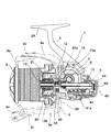
図7に示すように、リール本体1A内には、ハンドル軸7が一対の軸受け7a,7bを介して回転可能に支持されており、その突出端部には、ハンドル7cが取り付けられている。前記ハンドル軸7は、リール本体1Aの両サイドから突出するように支持されており、ハンドル7cは、公知のように、いずれか一方(右側巻き/左側巻き)に装着され、ハンドルを装着しない側のハンドル軸には、キャップ7dが取着されるようになっている。なお、図1では、上記したロータ3およびハンドル7cについては省略されている。
As shown in FIG. 7, a
前記ハンドル軸7には、巻き取り駆動機構が係合しており、この巻き取り駆動機構は、ハンドル軸7に一体回転可能に装着された駆動ギア8と、この駆動ギア8に噛合するピニオン歯部10aを具備してハンドル軸7と直交する方向に延出し且つ内部に軸方向に延在する空洞部が形成された回転駆動軸(駆動部)としてのピニオン10とを備えている。
A take-up drive mechanism is engaged with the
前記ピニオン10は、ピニオン歯部10aの前側と後側とがそれぞれ、リール本体1Aの支持部に嵌合支持された一対の軸受12a,12bにより、リール本体1A内に回転可能に支持されている。また、ピニオン10はスプール5側に向けて延出しており、ピニオン10の先端部にはロータ3がロータナットを介して一体回転可能に取り付けられている。
The
前記ピニオン歯部10aの前側に配置した軸受12aの前方側のピニオン10上には、逆転防止装置20を構成する一方向クラッチ21が取り付けられており、リール本体1Aの外部に設けられた切換操作部30を回動操作することで、ハンドル(ロータ3)の釣糸繰出し方向の逆回転を防止するようになっている。
すなわち、切換操作部30を回動操作することで、ロータ3を逆転防止状態(逆転防止装置のON状態)と、逆回転可能状態(逆転防止装置のOFF状態)の切り換えができるように構成されている。
A one-
That is, the
前記ピニオン10の内部に形成された空洞部には、ハンドル軸7と直交する方向に延出し、先端側にスプール5を装着したスプール軸15が軸方向に移動可能に挿通されている。前記スプール軸15は、ピニオン10に連結されるギアトレインを介して駆動されるスプール往復動装置40によって前後に往復動される。
A
前記スプール往復動装置40は、前記スプール軸15と平行となるようにリール本体内に回転可能に支持され、外周面に螺旋溝41aが形成された螺軸41と、前記螺旋溝41aに係合する係合ピン43aを保持し、前記スプール軸15の後端にビス43を介して固定された摺動子(スライダ)44と、摺動子44を前後方向に摺動するようにガイドするガイド軸45とを備えている(図7では、摺動子44の位置が図3の断面線C−Cの位置に前方側に移動したものとして示されている)。また、スプール往復動装置40は、図4に示すように、前記駆動ギア8によって回転駆動されるピニオン10の歯部10aと噛合する動力伝達ギア(ギアトレイン)47を備えている。本実施形態の動力伝達ギア47は、二段ギアとして構成されており、ピニオンの歯部10aと噛合する大径ギア47aと、大径ギアに併設される小径ギア47bとを備えており、この小径ギア47bが前記螺軸41の端部に固定された入力ギア41bに噛合することで、ハンドル軸7の回転駆動が減速されて前記螺軸41に伝達される。
The spool reciprocating
上記した構成により、ハンドル7cを巻き取り操作すると、駆動ギア8及びピニオン10を介してロータ3が回転駆動される共に、駆動ギア8、ピニオン10、動力伝達ギア(二段ギア)47、入力ギア41bを介して螺軸41が減速して回転駆動され、摺動子44に固定されたスプール軸15(スプール5)が前後方向に往復動される。したがって、釣糸は、回転駆動されるロータ3の釣糸案内部3dを介してスプール5に均等に巻回されるようになる。
According to the above configuration, when the
次に、上記した逆転防止装置20(一方向クラッチ21)、及び、これを指を掛けての操作で作動させる切換操作部30の構成について説明する。
図3に示すように、前記一方向クラッチ21は、ピニオン10に対して回り止め嵌合された内輪22と、内輪22の外側で複数の転がり部材26を周方向に亘って保持する保持器23と、保持器23の外側に配された外輪25とを有している。前記外輪25の内周面には、公知のように、保持器23によって保持された複数の転がり部材26がフリーに回転できるフリー回転領域と、複数の転がり部材26の回転を阻止する楔領域とが形成されており、各転がり部材26は、保持器23に設けられたバネ部材(図示せず)によって楔領域に付勢されている。
Next, the configuration of the reverse rotation prevention device 20 (one-way clutch 21) described above and the
As shown in FIG. 3, the one-
このような構成の一方向クラッチ21において、ピニオン10と共に内輪22が正回転(ロータ3が釣糸巻取り方向に回転)すると、保持器23に保持される転がり部材26が外輪25のフリー回転領域に位置され、そのため、内輪22の回転力が外輪25に伝達されず(外輪25によって阻止されず)、したがって、ピニオン10とともにロータ3が支障なく回転する。これに対して、ピニオン10と共に内輪22が逆回転(ロータ3が釣糸繰出し方向に回転)しようとすると、保持器23に保持される転がり部材26がバネ部材によって外輪25の楔領域に位置するため、内輪22の回転力が外輪25に伝達され、これがストッパとなって、ピニオン10及びロータ3の逆回転が阻止される(一方向クラッチの逆転防止状態;ON状態)。
In the one-way clutch 21 having such a configuration, when the
前記一方向クラッチ21の逆転防止機構の作動は、切換操作部30の回動操作によって、上記した逆転防止状態から逆転可能状態(OFF状態)に切り換えできるようになっている。具体的には、切換操作部30は、リール本体1A内でスプール軸15と略平行に延びる切り換え軸31を有しており、この切り換え軸31の先端突部31aは保持器23の径方向に延びる延出部23aの係合孔23bに係合して連結されている(図5、図6参照)。また、切り換え軸31の基端部はビス33によって切換操作部30に固定されており、切換操作部30を回動操作することにより、切り換え軸31を介して保持器23を周方向に回動させることが可能となっている。この場合、切り換え軸31には、リール本体1Aとの間で振り分けバネ36が取り付けられており、保持器23の回動位置を2か所(ON状態とOFF状態)で振り分け保持するように構成されている。
The operation of the reverse rotation prevention mechanism of the one-way clutch 21 can be switched from the reverse rotation prevention state to the reverse rotation possible state (OFF state) by the rotation operation of the switching
すなわち、切換操作部30を回動して、保持器23の回動位置がON状態(図4P1の位置)となるように振り分け保持されると、転がり部材26は、上記したように、内輪22(ピニオン)の正回転を許容するとともに逆回転を阻止する状態に保持される。また、切換操作部30を回動して、保持器23の回動位置がOFF状態(図4のP2の位置)となるように振り分け保持されると、転がり部材26は、バネ部材の付勢力に抗して外輪25のフリー回転領域に強制的に位置し、内輪22(ピニオン)の正回転及び逆回転を許容する状態に保持される。このように、切換操作部30を回動操作することで、ロータ3の正回転を許容して逆回転を防止する位置と、ロータ3の正逆回転を許容する位置との間で選択的に切り換え操作できるようになっている。
That is, when the switching
本実施形態の切換操作部30は、レバー形態で構成されており、リール本体1Aの側面の輪郭内で且つ前記ハンドル軸7に対して前記竿装着部2と反対側の領域に回動可能に配設されている。ここで、リール本体1Aの側面の輪郭とは、図2及び図3の点線Eで示すように、リール本体1Aの外形状を規定するエッジを意味しており、切換操作部30は、このエッジEの領域内に配設され、かつ、その領域から突出しない(露出しない)ように配設されている。
The switching
従来の魚釣用スピニングリールにおける逆転防止装置を作動させる切換操作部は、本体1Aの輪郭から突出する(外側にはみ出る)ように配設されていたため、実釣時に釣糸が絡みやすく、釣り場移動時や搬送中に他物が接触して破損などが生じる可能性があったが、本実施形態のように、リール本体1Aの輪郭内に配設し、ハンドル軸7に対して前記竿装着部2と反対側の領域に回動可能に配設したことで、外側にはみ出ることはなく、糸絡みや破損などを効果的に防止することが可能となる。
Since the switching operation unit that operates the reverse rotation prevention device in the conventional spinning reel for fishing is arranged so as to protrude from the contour of the
また、切換操作部30を、本体1Aの輪郭内に配設し、更には、ハンドル軸7の軸芯よりもスプール側に配設したことで、一方向クラッチの保持器23と連結される切り換え軸31の長さを短くすることができ、これにより連結部分での強度が向上して作動を安定化できるとともに、軽量化することが可能となる。また、切換操作部30がロータ側に近い位置にあることから、実釣時や取り扱い時に、ロータ3の径方向の膨出によって指などの他物が切換操作部30に誤って触れてしまうことがなく、逆転防止装置が誤作動することが防止できる。特に、本実施形態では、切換操作部30の少なくとも一部を、前記ロータ3の後端面3Aよりもスプール側に位置するように配設したことで、切換操作部30の一部がロータ3によって覆われた状態となり、他物が接触等し難くなり、破損や誤作動などを確実に防止することができる。
Further, by arranging the switching
また、本実施形態では、回動操作される切換操作部30を、レバー形態としており、その基端側を前記ビス33によって支持し、リール本体の1Aの側面(リール本体を閉塞するカバー体)1Cに対して、図4に示すように、起伏するように構成しているため、特許文献1に開示された構成のように、竿装着部の後側で幅方向に回動配設する構成と比較して、一方向クラッチの状態を直ちに把握することが可能となる。この場合、実釣時等において、逆転防止装置をOFF状態(逆転可能状態)に切り換えておくことは稀であることから、リール本体1Aの側面に沿うように倒伏して保持された状態P1を逆転防止状態(ON状態)とし、逆転可能状態(OFF状態)では、リール本体1Aの側面から起立した状態P2に夫々切り換え保持することが好ましい。
Further, in the present embodiment, the switching
また、前記リール本体1Aの側面(カバー体)1Cの表面に凹部1dを形成しておき、切換操作部30が倒伏した際、切換操作部が表面からできるだけ突出しないように構成する(切換操作部30と側面1Cが略面一状になる)ことが好ましい。このような構成によれば、糸絡みをより効果的に防止できるとともに、他物が引っ掛かることが確実に防止できる。
Further, a recess 1d is formed on the surface of the side surface (cover body) 1C of the
また、上記したような切換操作部30を起伏させる構成では、切換操作部30を倒伏したON状態で、リール本体の側面1Cとの間で空間が生じるように切り換え保持させることが好ましい。例えば、本実施形態では、前記凹部1d内に凸部1eを形成しており、切換操作部30が倒伏した際に、凸部1eに当て付いて、回動位置を規制しており、凸部によって空間Sが生じるようにしている。
Further, in the configuration in which the
このような構成によれば、切換操作部30をON状態からOFF状態に回動操作する際、空間Sにより指を引っ掛け易くなり、操作性の向上が図れる。なお、このような空間Sを形成する方法としては、上記以外にも、切換操作部30の先端側を細径化しても良いし、先端側にテーパ30cを形成しても良い。
According to such a configuration, when the switching
以上、本発明の実施形態について説明したが、本発明は、上記した実施形態に限定されることはなく、種々変形することが可能である。上述した実施形態では、回動操作される切換操作部30は、レバー形態としたが、指で押し付けて回動操作可能なダイヤル式にしても良いし、ダイヤルの一部に指で摘まめるように突起を有する構成にする等、適宜変形することが可能である。また、切換操作部30の配設位置は、図3のエッジEの範囲内に納まっていればよく、その位置については適宜変形することが可能である。また、本発明は、逆転防止装置を作動させる切換操作部に特徴があり、それ以外の構成については、図に示した実施形態の構成に限定されることはない。
Although the embodiments of the present invention have been described above, the present invention is not limited to the above-described embodiments and can be variously modified. In the above-described embodiment, the switching
1 魚釣用スピニングリール
1A リール本体
2A 竿装着部
3 ロータ
5 スプール
7 ハンドル軸
10 ピニオン
20 逆転防止装置
21 一方向クラッチ
30 切換操作部
E リール本体の側面の輪郭
1 Spinning reel for
Claims (2)
前記ロータの釣糸巻き取り時における逆回転を防止する逆転防止装置と、この逆転防止装置を作動させて前記ロータを逆転防止状態と逆転可能状態に切り換える切換操作部と、を有し、
前記切換操作部を、前記リール本体の側面の輪郭内で且つ前記ハンドル軸に対して前記竿装着部と反対側の領域に回動可能に配設するとともに、前記ハンドル軸の軸芯よりもスプール側に配設し、かつ、前記切換操作部の少なくとも一部は、前記ロータ後端面よりもスプール側に位置されていることを特徴とする魚釣用スピニングリール。 A spinning reel for fishing in which a rotor having a handle shaft and a fishing thread guide portion is rotatably supported on a reel body provided with a rod mounting portion, and the rotor is rotated by a rotation operation of the handle shaft to wind a fishing thread around a spool. In
It has a reverse rotation prevention device that prevents reverse rotation when the fishing thread of the rotor is wound, and a switching operation unit that operates the reverse rotation prevention device to switch the rotor between a reverse rotation prevention state and a reverse rotation possible state.
The switching operation unit is rotatably arranged in the contour of the side surface of the reel body and in a region opposite to the rod mounting portion with respect to the handle shaft, and is spooled from the shaft core of the handle shaft. A spinning reel for fishing, which is arranged on the side and at least a part of the switching operation unit is located on the spool side with respect to the rear end surface of the rotor.
前記ロータの釣糸巻き取り時における逆回転を防止する逆転防止装置と、この逆転防止装置を作動させて前記ロータを逆転防止状態と逆転可能状態に切り換える切換操作部と、を有し、
前記切換操作部を、前記リール本体の側面の輪郭内で且つ前記ハンドル軸に対して前記竿装着部と反対側の領域に回動可能に配設するとともに、前記切換操作部はレバー形態であり、逆転防止状態(ON状態)では前記リール本体の側面に沿うように倒伏し、逆転可能状態(OFF状態)では、前記リール本体の側面から起立した状態に夫々切換保持されることを特徴とする魚釣用スピニングリール。
A spinning reel for fishing in which a rotor having a handle shaft and a fishing thread guide portion is rotatably supported on a reel body provided with a rod mounting portion, and the rotor is rotated by a rotation operation of the handle shaft to wind a fishing thread around a spool. In
It has a reverse rotation prevention device that prevents reverse rotation when the fishing thread of the rotor is wound, and a switching operation unit that operates the reverse rotation prevention device to switch the rotor between a reverse rotation prevention state and a reverse rotation possible state.
The switching operation unit is rotatably arranged in the contour of the side surface of the reel body and in a region opposite to the rod mounting portion with respect to the handle shaft, and the switching operation unit is in the form of a lever. In the reverse rotation prevention state (ON state), the reel body is laid down along the side surface, and in the reverse rotation possible state (OFF state), the reel body is switched and held in a standing state from the side surface. Spinning reel for fishing.
Priority Applications (1)
| Application Number | Priority Date | Filing Date | Title |
|---|---|---|---|
| JP2017237315A JP6871142B2 (en) | 2017-12-12 | 2017-12-12 | Spinning reel for fishing |
Applications Claiming Priority (1)
| Application Number | Priority Date | Filing Date | Title |
|---|---|---|---|
| JP2017237315A JP6871142B2 (en) | 2017-12-12 | 2017-12-12 | Spinning reel for fishing |
Publications (2)
| Publication Number | Publication Date |
|---|---|
| JP2019103426A JP2019103426A (en) | 2019-06-27 |
| JP6871142B2 true JP6871142B2 (en) | 2021-05-12 |
Family
ID=67060617
Family Applications (1)
| Application Number | Title | Priority Date | Filing Date |
|---|---|---|---|
| JP2017237315A Active JP6871142B2 (en) | 2017-12-12 | 2017-12-12 | Spinning reel for fishing |
Country Status (1)
| Country | Link |
|---|---|
| JP (1) | JP6871142B2 (en) |
-
2017
- 2017-12-12 JP JP2017237315A patent/JP6871142B2/en active Active
Also Published As
| Publication number | Publication date |
|---|---|
| JP2019103426A (en) | 2019-06-27 |
Similar Documents
| Publication | Publication Date | Title |
|---|---|---|
| JP6649801B2 (en) | Double bearing reel | |
| KR20060124572A (en) | Spinning reel | |
| JP6407578B2 (en) | Double bearing reel and double bearing reel clutch mechanism | |
| KR101081832B1 (en) | Level winding mechanism for a dual bearing reel | |
| JP2016002062A5 (en) | ||
| KR102228645B1 (en) | Roller clutch for fishing reel and spinning reel using the same | |
| KR100450629B1 (en) | Spinning Reel with Narrow Reel Body Housing | |
| KR100656501B1 (en) | Device for guiding fishline of spinning reel | |
| JP6871142B2 (en) | Spinning reel for fishing | |
| JP2018050587A5 (en) | ||
| JP5008693B2 (en) | Spinning reel spool | |
| JP2005000103A (en) | Spool supporting structure of spinning reel | |
| JP2006333705A (en) | Spinning reel | |
| JP4476128B2 (en) | Spinning reel master gear | |
| JP6871151B2 (en) | Spinning reel for fishing | |
| JP6976814B2 (en) | Spinning reel | |
| JP6376756B2 (en) | Fishing reel reciprocating mechanism | |
| JP2011177154A (en) | Fishing reel | |
| JP4346632B2 (en) | Spinning reel spool | |
| KR100620492B1 (en) | Spool and auxiliary winder of spinning reel | |
| JP4389815B2 (en) | Fishing spinning reel | |
| JP4351690B2 (en) | Spinning reel spool | |
| JP6876159B2 (en) | Double bearing reel | |
| JP6143657B2 (en) | Fishing reel | |
| JP4420732B2 (en) | Spinning reel rotor braking device |
Legal Events
| Date | Code | Title | Description |
|---|---|---|---|
| A621 | Written request for application examination |
Free format text: JAPANESE INTERMEDIATE CODE: A621 Effective date: 20200221 |
|
| A977 | Report on retrieval |
Free format text: JAPANESE INTERMEDIATE CODE: A971007 Effective date: 20210120 |
|
| A131 | Notification of reasons for refusal |
Free format text: JAPANESE INTERMEDIATE CODE: A131 Effective date: 20210128 |
|
| A521 | Request for written amendment filed |
Free format text: JAPANESE INTERMEDIATE CODE: A523 Effective date: 20210310 |
|
| TRDD | Decision of grant or rejection written | ||
| A01 | Written decision to grant a patent or to grant a registration (utility model) |
Free format text: JAPANESE INTERMEDIATE CODE: A01 Effective date: 20210325 |
|
| A61 | First payment of annual fees (during grant procedure) |
Free format text: JAPANESE INTERMEDIATE CODE: A61 Effective date: 20210415 |
|
| R150 | Certificate of patent or registration of utility model |
Ref document number: 6871142 Country of ref document: JP Free format text: JAPANESE INTERMEDIATE CODE: R150 |
|
| R250 | Receipt of annual fees |
Free format text: JAPANESE INTERMEDIATE CODE: R250 |