JP6869945B2 - Foam cartridge, refill unit, foam dispenser, and foam dispenser system - Google Patents
Foam cartridge, refill unit, foam dispenser, and foam dispenser system Download PDFInfo
- Publication number
- JP6869945B2 JP6869945B2 JP2018500786A JP2018500786A JP6869945B2 JP 6869945 B2 JP6869945 B2 JP 6869945B2 JP 2018500786 A JP2018500786 A JP 2018500786A JP 2018500786 A JP2018500786 A JP 2018500786A JP 6869945 B2 JP6869945 B2 JP 6869945B2
- Authority
- JP
- Japan
- Prior art keywords
- foam
- stage
- pump
- dispenser
- liquid
- Prior art date
- Legal status (The legal status is an assumption and is not a legal conclusion. Google has not performed a legal analysis and makes no representation as to the accuracy of the status listed.)
- Active
Links
- 239000006260 foam Substances 0.000 title claims description 174
- 239000007788 liquid Substances 0.000 claims description 97
- 238000005187 foaming Methods 0.000 claims description 26
- 239000003570 air Substances 0.000 description 57
- 239000000203 mixture Substances 0.000 description 12
- LFQSCWFLJHTTHZ-UHFFFAOYSA-N Ethanol Chemical compound CCO LFQSCWFLJHTTHZ-UHFFFAOYSA-N 0.000 description 7
- 239000000645 desinfectant Substances 0.000 description 3
- 238000005086 pumping Methods 0.000 description 3
- 241000272525 Anas platyrhynchos Species 0.000 description 2
- 238000007599 discharging Methods 0.000 description 2
- 239000012530 fluid Substances 0.000 description 2
- 239000000344 soap Substances 0.000 description 2
- 235000001674 Agaricus brunnescens Nutrition 0.000 description 1
- 239000012190 activator Substances 0.000 description 1
- 210000003323 beak Anatomy 0.000 description 1
- 230000015572 biosynthetic process Effects 0.000 description 1
- 239000012459 cleaning agent Substances 0.000 description 1
- 239000004519 grease Substances 0.000 description 1
- 239000010687 lubricating oil Substances 0.000 description 1
- 239000000463 material Substances 0.000 description 1
- 238000012986 modification Methods 0.000 description 1
- 230000004048 modification Effects 0.000 description 1
- 230000001737 promoting effect Effects 0.000 description 1
- 238000005728 strengthening Methods 0.000 description 1
- 238000013022 venting Methods 0.000 description 1
- 238000003466 welding Methods 0.000 description 1
Images


Classifications
-
- A—HUMAN NECESSITIES
- A47—FURNITURE; DOMESTIC ARTICLES OR APPLIANCES; COFFEE MILLS; SPICE MILLS; SUCTION CLEANERS IN GENERAL
- A47K—SANITARY EQUIPMENT NOT OTHERWISE PROVIDED FOR; TOILET ACCESSORIES
- A47K5/00—Holders or dispensers for soap, toothpaste, or the like
- A47K5/14—Foam or lather making devices
-
- A—HUMAN NECESSITIES
- A47—FURNITURE; DOMESTIC ARTICLES OR APPLIANCES; COFFEE MILLS; SPICE MILLS; SUCTION CLEANERS IN GENERAL
- A47K—SANITARY EQUIPMENT NOT OTHERWISE PROVIDED FOR; TOILET ACCESSORIES
- A47K5/00—Holders or dispensers for soap, toothpaste, or the like
- A47K5/06—Dispensers for soap
- A47K5/12—Dispensers for soap for liquid or pasty soap
- A47K5/1211—Dispensers for soap for liquid or pasty soap using pressure on soap, e.g. with piston
-
- B—PERFORMING OPERATIONS; TRANSPORTING
- B05—SPRAYING OR ATOMISING IN GENERAL; APPLYING FLUENT MATERIALS TO SURFACES, IN GENERAL
- B05B—SPRAYING APPARATUS; ATOMISING APPARATUS; NOZZLES
- B05B11/00—Single-unit hand-held apparatus in which flow of contents is produced by the muscular force of the operator at the moment of use
- B05B11/01—Single-unit hand-held apparatus in which flow of contents is produced by the muscular force of the operator at the moment of use characterised by the means producing the flow
- B05B11/10—Pump arrangements for transferring the contents from the container to a pump chamber by a sucking effect and forcing the contents out through the dispensing nozzle
- B05B11/1087—Combination of liquid and air pumps
-
- B—PERFORMING OPERATIONS; TRANSPORTING
- B05—SPRAYING OR ATOMISING IN GENERAL; APPLYING FLUENT MATERIALS TO SURFACES, IN GENERAL
- B05B—SPRAYING APPARATUS; ATOMISING APPARATUS; NOZZLES
- B05B7/00—Spraying apparatus for discharge of liquids or other fluent materials from two or more sources, e.g. of liquid and air, of powder and gas
- B05B7/0018—Spraying apparatus for discharge of liquids or other fluent materials from two or more sources, e.g. of liquid and air, of powder and gas with devices for making foam
- B05B7/0025—Spraying apparatus for discharge of liquids or other fluent materials from two or more sources, e.g. of liquid and air, of powder and gas with devices for making foam with a compressed gas supply
- B05B7/0031—Spraying apparatus for discharge of liquids or other fluent materials from two or more sources, e.g. of liquid and air, of powder and gas with devices for making foam with a compressed gas supply with disturbing means promoting mixing, e.g. balls, crowns
- B05B7/0043—Spraying apparatus for discharge of liquids or other fluent materials from two or more sources, e.g. of liquid and air, of powder and gas with devices for making foam with a compressed gas supply with disturbing means promoting mixing, e.g. balls, crowns including a plurality of individual elements, e.g. needles, baffles, rotatable blades
Description
本出願は、2015年7月15日に出願され、「改良された発泡カートリッジ、ポンプ、詰め替えユニット、及びそれらを使用する泡分注器」と題する米国非仮出願第62/192,837号の優先権及び利益を主張し、その全体が参照により本明細書に組み込まれる。 This application was filed on July 15, 2015, in US Non-Provisional Application No. 62 / 192,837, entitled "Improved Foam Cartridges, Pumps, Refill Units, and Foam Dispensers Using them." Claim priority and interests, which are incorporated herein by reference in their entirety.
本発明は、一般に、泡ポンプ、泡分注器の詰め替えユニット、及び泡分注器システムに関し、より詳細には、泡ポンプ、詰め替えユニット、及び改良された発泡カートリッジを有する泡分注器に関する。 The present invention generally relates to a foam pump, a foam dispenser refill unit, and a foam dispenser system, and more particularly to a foam pump, a refill unit, and a foam dispenser having an improved foam cartridge.
液体石鹸及び消毒剤の分注器等の液体分注器システムは、分注器の作動によって使用者に所定量の液体を提供する。さらに、例えば液体に空気を注入して液体と気泡の泡状混合物を生成することによって、泡状の液体を分注することが望ましい場合がある。液体の中には、例えば、アルコール系液体等のように、発泡が難しく、混合を強化する必要があるものがある。泡を発生させるためのポンプは液体及び空気の混合物を、発泡カートリッジを通して圧送することで泡を形成することができる。従来の泡ポンプ及び発泡カートリッジは、2013年3月9日に出願された「水平ポンプ、詰め替えユニット、及び一体型空気圧縮機を備えた泡分注器」と題する米国特許出願公開第2014/0054323号、2013年3月18日に出願された「空動きを有する泡ポンプ及び出力調節可能な泡ポンプ」と題する米国特許第8,955,718号、2013年7月3日に出願された「分岐した泡ポンプ、分注器及び詰め替えユニット」と題する米国特許第8,763,863号、及び2008年1月24日に出願され、「改良されたピストン構造を有する泡ポンプ」と題する米国特許第7,850,049号(これらの全ては、その全体が参照により本明細書に組み込まれる)に開示されている。 Liquid dispenser systems, such as liquid soap and disinfectant dispensers, provide the user with a predetermined amount of liquid by operating the dispenser. Further, it may be desirable to dispense the foamy liquid, for example by injecting air into the liquid to produce a foamy mixture of the liquid and bubbles. Some liquids, such as alcohol-based liquids, are difficult to foam and require strengthening of mixing. A pump for generating bubbles can form bubbles by pumping a mixture of liquid and air through a foam cartridge. Conventional foam pumps and foam cartridges are available in US Patent Application Publication No. 2014/0054323, entitled "Foam Dispenser with Horizontal Pump, Refill Unit, and Integrated Air Compressor," filed March 9, 2013. No. 8,955,718, US Pat. No. 8,955,718, filed March 18, 2013, entitled "Foam Pumps with Air Motion and Adjustable Output Foam Pumps," filed July 3, 2013. US Pat. No. 8,763,863 entitled "Branched Foam Pumps, Dispensers and Refill Units" and US Patents filed January 24, 2008 entitled "Foam Pumps with Improved Piston Structure" No. 7,850,049, all of which are incorporated herein by reference in their entirety.
泡分注器、泡分注器用の詰め替えユニット、及び発泡カートリッジの典型的な実施形態を本明細書に開示する。典型的な泡ポンプ用発泡カートリッジは、一定の内径を有する筐体、筐体内に配置された第1の発泡段、及び筐体内に配置された第2の発泡段を含む。第1の発泡段は第2の発泡段から離れている。第1の発泡段は少なくとも2つの異なる種類の混合媒体を有し、第2の発泡段は少なくとも2つの異なる種類の混合媒体を有する。 Typical embodiments of foam dispensers, refill units for foam dispensers, and foam cartridges are disclosed herein. A typical foam cartridge for a foam pump includes a housing having a constant inner diameter, a first foam stage arranged in the housing, and a second foam stage arranged in the housing. The first foaming stage is separated from the second foaming stage. The first foam stage has at least two different types of mixed media and the second foam stage has at least two different types of mixed media.
本発明のこれら及び他の特徴及び利点は、以下の説明及び添付の図面を参照することでより良く理解される。
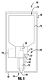
図1は、泡分注器100の典型的な実施形態を示す。図1の断面図は、泡出口部130、容器116、及び作動装置140を有する泡ポンプ120を示すために筐体102を切断したものである。分注器100は、使い捨て詰め替えユニット110を含む。使い捨て詰め替えユニット110は容器116、泡ポンプ120、及び泡出口部130を含む。分注器100は壁取り付けシステム、調理台取り付けシステム、場所から場所へ移動可能な未取り付け可搬システム、又は他の種類の分注器システムであってもよい。
FIG. 1 shows a typical embodiment of the
容器116は、使い捨て詰め替えユニット110内に分注可能な発泡性液体の供給物を収容する液槽を形成する。様々な実施形態において、収容される液体は、例えば、消毒剤、洗浄剤、殺菌剤、又は他の何らかの分注可能な液体であってもよい。典型的な使い捨て詰め替えユニット110では、容器116は折り畳み可能な容器であり、薄いプラスチックの又は可撓性の袋状材料から作製することができる。他の実施形態では、容器116は折り畳みできない容器であってもよく、例えば折り畳み可能な容器よりも厚いプラスチックで作製することができる。折り畳みできない容器は、通常、容器を通気するための通気口(図示せず)を含む。
The
容器116は、詰め替え、交換、或いは詰め替えと交換との両方できると有利である。取り付けられている使い捨て詰め替えユニット110の容器116内に貯蔵された液体を使い果たした場合、あるいは取り付けられている詰め替えユニット110が故障した場合には、取り付けられている詰め替えユニット110を分注器100から取り外すことができる。次いで、空の又は故障した使い捨て詰め替えユニット110は新しい使い捨て詰め替えユニット110と取り替えてもよい。詰め替えユニット110は、例えば、解除可能な係止機構、4分の1回転接続、ねじ式接続、フランジと締結具による接続、締め付け接続、又は任意の他の再使用可能な接続等の任意の手段によって分注器100内に固定することができる。
It is advantageous for
詰め替えユニット110は容器116と流体連通する泡ポンプ120を含む。泡ポンプ120は、例えば、ねじ式接続、溶接接続、4分の1回転接続、スナップ嵌合接続、締め付け接続、フランジと締結具による接続等の任意の手段によって容器116に固定することができる。泡ポンプ120は、泡出口部を通して液体及び空気を圧送し、ポンプの出口ノズル134で濃厚な泡を分注する。
The refill unit 110 includes a
分注器100に用いることができる泡ポンプには多くの異なる種類が存在するため、泡ポンプ120を包括的に図示する。例えば、2004年6月13日に出願された「発泡カートリッジ、ポンプ、詰め替えユニット、及びこれらを利用した泡分注器」と題する米国特許出願公開第2014/0367419号、及び2008年12月3日に出願された「傾斜スロット泡分注器」と題する米国特許8,272,539号(これらの全体が参照によって組み込まれる)に開示された泡ポンプを分注器100に使用してもよい。
Since there are many different types of foam pumps that can be used in the
一実施形態では、泡ポンプ120の空気ポンプ及び液体ポンプはポンプ筐体121内に入っている。他の一実施形態では、泡ポンプ120は独立した空気ポンプ及び液体ポンプを含む。この実施形態では、液体ポンプ及び空気ポンプは両方とも詰め替えユニット110の一部であってもよい。他の実施形態では、液体ポンプは、詰め替えユニット110の一部であってもよく、容器116からの液体が使い尽くされた場合は廃棄してもよい。一方、空気ポンプ(図示せず)は分注器100に取り付けられてもよく、廃棄はされない。空気ポンプ部分から分離可能な液体ポンプ部分を有する泡ポンプを有するという概念は、2013年7月3日に出願された「分岐した泡ポンプ、分注器及び詰め替えユニット」と題する米国特許第8,763,863号に図示され記載されている「分割ポンプ」と呼ばれ、本明細書に全体として組み込まれる。
In one embodiment, the air pump and liquid pump of the
泡出口130は泡ポンプ120の予混合室122と流体連通している。泡媒体132は泡出口130内に保持されている。泡媒体132は任意の発泡可能な液体から泡を生成する。いくつかの実施形態は、アルコールを含有する発泡性液体の発泡促進に特によく適している。例えば、泡媒体132は従来の発泡カートリッジよりも長く、濃厚な泡を生成する複数の離間した発泡段(図2,3参照)を含む。いくつかの実施形態では、泡は作動速度及び圧力の上昇で生成される。
The
分注器100は、1つ以上の作動装置140を含む。本明細書では、作動装置すなわち作動部材又は作動機構は、分注器100に液体、空気及び/又は泡を移動させる1つ以上の部品を含む。
The
分注器100に用いることのできる多くの異なる種類のポンプ作動装置が存在するため、作動装置140を包括的に図示する。分注器100の作動装置140は任意の型の作動装置でよく、例えば、手動レバー、手動引張棒、手動押棒、手動回転可能クランク、電気起動式作動装置、又は泡ポンプ120(液体ポンプ部及び空気ポンプ部の一方又は両方を含む)を作動させるための任意の他の手段であってもよい。電子作動装置は、非接触操作を備えたハンズフリー分注器システムを提供するためのセンサー(図示せず)をさらに含むことができる。
Since there are many different types of pump actuators that can be used in the
分注器100の動作中、液体は液体入口126を通して泡ポンプ120によって容器116から引き込まれ、予混合室122に圧送される。同時に、空気は空気入口124を通して泡ポンプ120に引き込まれ、予備混合室122内に圧送され、液体と混合される。空気と液体の混合物は、泡媒体132を通って泡出口部130に押し込まれ、濃厚な泡を出口ノズル134から分注する。泡媒体132は、例えば、篩、多孔質部材、スポンジ、邪魔板等の、高品質の泡を生成する少なくとも2つの混合媒体の組み合わせをそれぞれ含む2つの発泡段を含む。筐体102の底板103の開口115によって、ノズル126から吐出された泡を使用者が使えるように筐体102から出される。
During the operation of the
図2に、典型的な詰め替えユニット210を形成するために容器212に取り付けられた泡ポンプ230を含む泡分注器200の典型的な実施形態を示す。発泡性液体は容器212に貯蔵され、泡ポンプ230内の空気と混合されて、ポンプ出口227から分注される濃厚な泡を生成する。図示された実施形態では、泡ポンプ230はポンプ230が作動すると同時に作動する液体室及び空気室を備えたピストンポンプを含む。泡ポンプ230は、泡を生成するために液体と空気を送り出して混合するのに適した任意の種類のポンプであってよい。
FIG. 2 shows a typical embodiment of a
容器212の内部は発泡性液体を保持する液槽220を形成する。容器212の首部214は泡ポンプ230の襟部238内に収容される。図示された実施形態では、容器212はねじ式接続で泡ポンプ230に固定されているが、容器212は、例えば、スナップ嵌合接続、摩擦嵌合接続、4分の1回転接続、フランジと締結具による接続、締め付け接続等の任意の手段によって、泡ポンプ230に固定することができる(実際には一回限りの接続が好ましい)。
The inside of the
泡ポンプ230は、ポンプ筐体231、ピストン組立体240、泡出口260及びバネ241を含む。ポンプ筐体231は、環状の外側筐体232、環状の内側筐体234、端部蓋236及び襟部238を含む。ポンプ筐体231の端部蓋236は容器に近接して配置され、環状の外側筐体232及び内側筐体234の閉鎖端部を形成する。ピストン組立体240は、ピストン本体242、外側孔243、内側ピストン本体244、内側孔245、出口部246、及び出口孔247を含む。図示した実施形態では、内側ピストン本体244は分離した構成要素として示されているが、ピストン本体242の一部として一体的に形成されていてもよい。バネ241は、ピストン組立体240のポンプ出口部246の内部の肩部248とポンプ筐体231の端部蓋238の内部とを係合させる。
The foam pump 230 includes a
ポンプ筐体231及びピストン組立体240は、円筒状液体ポンプ室222及び環状空気ポンプ室224を形成する。液体ポンプ室222は、内側環状筐体234、端部蓋236、及び内側ピストン本体244によって少なくとも部分的に形成される。空気ポンプ室224は、環状外側筐体232、端部蓋236、ピストン本体242、及び外側孔243によって少なくとも部分的に形成される。予混合室226は中央孔245に入っている。端部蓋236の液体ポンプ入口221は、液槽220及び液体ポンプ室222と流体連通している。液体ポンプ出口223は、液体ポンプ室222及び予混合室226と流体連通している。開口部225によって、予混合室226と流体連通するように空気ポンプ室224は配置されている。ポンプ出口部246及び泡出口260は、予混合室226及び大気と流体連通するポンプ出口227を形成する。
The
ピストン組立体240は、ポンプ筐体231に摺動可能に係合する。筐体231内のピストン240が充填状態と放出状態との間で移動することにより、液体ポンプ室222及び空気ポンプ室224の容積が膨張・収縮する。ピストン240は手動又は作動装置によって作動させることができる。本明細書では、作動装置すなわち作動部材又は作動機構は、分注器200に液体、空気又は泡を移動させる1つ以上の部品を含む。ピストン240を上方へ作動することによって、ピストン240は充填状態から放出状態に変化し、バネ241を圧縮する。上向きの作動力が除去されると、バネ241は、ピストン240を充填状態に戻し、液体室222及び空気室224を膨張させ、それによってポンプ230を充填する。ピストン240は、任意の手段、例えば電気低作動装置、機械的作動装置、空気圧作動装置等によって移動させることができる。
The
環状の空気ポンプ室224は、円筒状液体ポンプ室222よりも容積が大きい。従って、ピストン240の作動により、液体よりも多量の空気が泡ポンプ230を通して圧送される。空気ポンプ室224及び液体ポンプ室222の寸法(例えば、直径)を調整することにより、空気と液体との流速比を調節することができる。空気の流速は、例えば、液体の流速の約1倍〜約20倍、好ましくは液体の流速の約10倍であってもよい。
The annular
液入口弁250は、ポンプ筐体231の端部蓋236の液入口221に配置される。液入口弁250は、流れを液ポンプ入口221を通って液ポンプ室222に流入させ、液ポンプ室222から流出するのを防止するように配置された一方向弁である。液出口弁252は、内部ピストン本体244の端部に配置されている液出口弁252は、流れを液ポンプ出口223を通って液ポンプ室222から流出させ、液ポンプ室222に流入するのを防止をするように配置された一方向弁である。いくつかの実施形態では、液入口弁250及び液出口弁252は、任意の種類の一方向弁であってよく、例えば、ボール・スプリング弁、ワイパー弁、ポペット弁、フラッパー弁、傘弁、スリット弁、マッシュルーム弁、及びダックビル(アヒルのくちばし形)弁等が挙げられる。
The
内側ピストン本体244表面の液ポンプシール254は、ポンプ230の充放出中に液ポンプ室222から液体が漏れるのを防ぐために、内側ポンプ筐体234を封止する。液ポンプシール254は、一体成形のワイパーシールとして図示されているが、任意の種類の適切なシールでよく、例えば、Oリング又は弾性体ワッシャー等が挙げられる。
The
ピストン本体242上の空気ポンプシール256は、外側ポンプ筐体232を封止する。空気ポンプシール256は、吐出作動サイクル中に空気ポンプ室224を密閉するが、充填サイクル中に空気が空気ポンプ室224に入ることを可能にする。従って、空気ポンプシール256は、空気を空気ポンプ室224内に流入させ、空気ポンプ室224から流出するのを防止するように配置された一方向弁として動作する。いくつかの他の実施形態では、泡ポンプ230は、空気ポンプ室224を大気に流体接続する別個の一方向空気入口弁(図示せず)を含んでもよい。別個の一方向空気入口弁(図示せず)を含む実施形態の空気ポンプシール256は、任意の適切なシールでよく、例えば、Oリング、弾性体ワッシャー、一体成形ワイパーシール等、あるいは、例えば、グリース等の潤滑油が挙げられる。
The
泡出口260は、ピストン組立体240の出口部246に取り付けられ、ポンプ出口227を共に形成する出口孔247と流体連通する中央孔264を含む。泡出口260のノズル262は、泡出口260で生成された泡を使用者に分注することを可能にする。泡出口260は、例えば4分の1回転接続、フランジと締結具による接続、締め付け接続、摩擦嵌合接続等の任意の手段によってピストン本体240に固定することができる。いくつかの実施形態では、発泡出口260は、ピストン本体240に溶接又は接着されてもよく、又はピストン本体240と一体的に形成されてもよい。
The bubble outlet 260 includes a central hole 264 that is attached to the outlet portion 246 of the
第1の発泡媒体272及び第2の発泡媒体274を含む発泡カートリッジ270は、ポンプ出口227内に保持される。第1の発泡段272及び第2の発泡段274のそれぞれは、少なくとも2つの混合媒体の組み合わせ、例えば、篩、多孔質部材、スポンジ、邪魔板等の少なくとも2つの組み合わせ等を含む。第1の発泡段272及び第2の発泡段274は、間隙276によって分離されている。いくつかの実施形態では、間隙はポンプ出口227の内径の約10%〜約50%にほぼ等しい。
The
防塵蓋280は、分注器200の出口部分を隠して保護するためにポンプ筐体230に取り付けられ、分注器200に詰め替えユニット210を取り付ける前に取り外される。
The
分注器200の動作中、泡ポンプ230のピストン組立体240は、バネ241によって放出位置から充填位置に移動される。発泡性液体は、液槽220から液体ポンプ入口221及び液体ポンプ入口弁250を通って、液体ポンプ室222が拡張するのに伴い液体ポンプ室222内に流れる。同時に、空気は、空気ポンプ室シール256を通って空気ポンプ室224に流れる。分注器200が作動すると、ピストン240は、充填位置から放出位置に移動し、液体ポンプ室222から液体ポンプ出口弁252及び液体ポンプ出口223を通って予混合室226に液体を押し出す。同時に、空気は空気ポンプ室224から開口部225を通って予混合室226に押し出され、発泡性液体と混合される。予混合室226内の空気と液体の混合物は予混合室226から出て発泡カートリッジ270を通って流れ、ポンプ出口227に濃厚な泡を生成する。
During the operation of the
分注器200は、短時間で濃厚な泡を生成するために高速かつ高圧で作動される。作動装置(図示せず)は、ピストンを約1.5〜4インチ(3.81〜10.16cm)/秒で動かす。この高速で作動すると、分注器200は、約0.2〜約0.5秒で約5ml〜約19.5mlの泡を生成する。圧送後で、空気と液体の混合物が発泡カートリッジを通って流れる前では、空気と液体の混合物中の圧力は約4psig〜約12psigの範囲である。発泡カートリッジ260とは異なり、従来の発泡カートリッジは、これらの流速及び圧力では、アルコールを含有する発泡性液体から濃厚で均一な発泡体を生成することができない。
The
図3は、泡分注器200の泡出口301に配置された典型的な発泡カートリッジ300の拡大断面図である。発泡カートリッジ300の構成要素をより明確に示すために、図3には、発泡出口301が概略的に示されている。発泡カートリッジ300は、間隙330によって分離された第1の発泡段310及び第2の発泡段320を含む。空気と液体の混合物は、入口302で発泡カートリッジ300に入り、流れ方向306に移動しながら出口304から濃厚な泡として分注される。第1の発泡段310は、粗い篩312、スポンジ314、及び細かい篩316を含む。第2の発泡段320は、スポンジ322及び細かい篩324を含む。粗い篩312は、約40〜約80本/インチ(2.54cm)の糸を有する濾材であってもよい。細かい篩316及び324は、約80〜約200本/インチ(2.54cm)の糸を有する濾材であってもよい。スポンジ314及び322は、約10孔/インチ(2.54cm)〜約100孔/インチ(2.54cm)の多孔質媒体であってもよい。
FIG. 3 is an enlarged cross-sectional view of a
発泡カートリッジ300は、空気と液体との混合を促進し、泡立ちにくい液体、例えば、アルコールを含む液体や高圧で高速の泡ポンプから吐出される液体等に特に有用である。作動速度が速くなると、一定量の泡を使用者の手に分注するのに必要な時間が短縮され、ポンプ内の空気及び液体の圧力並びに速度が増加する。例えば、分注器の1.5〜4インチ(3.81〜10.16cm)/秒という高速によって、空気と液体の混合物中の圧力が約4psig〜約12psigの範囲となる。この速度で作動するポンプは、約0.2秒〜約0.5秒で約5ml〜約19.5mlを分注することができる。泡を分注する時間を短縮することは、時間に対する要求が高く、時間のコストが相当かかる医療従事者に特に重要である。
The
発泡カートリッジの各段310,320は、泡ポンプから出る空気と液体の混合物の圧力を下げ、アルコールを含有する発泡性液体の使用時にカートリッジ300の出口304においてより安定した気泡が形成されることを可能にする。アルコール系発泡性液体中に形成された気泡は、表面張力が低いため、石鹸液体中に形成された気泡と同じ圧力で気泡を維持することができないので、液体と空気の混合物の圧力を下げることにより、アルコール系発泡性液体からの濃厚な泡の形成を促進する。
Each
第1の発泡段310に入る空気と液体の混合物は、粗い篩312を通過して混合物中の気泡の大きさをより均一にする。次いで、気泡はスポンジ314を通過し、連続的に改質される。細かい篩316は、気泡を小さくし、精細化する。第1の発泡段310と第2の発泡段320との間の間隙330によって、第2段320に入る前に細かい篩316から出る気泡が十分に形成される。隙間330は、発泡カートリッジ300の内径の約10%であってもよいし、発泡カートリッジ300の内径の約10%〜約50%であってもよい。第1の発泡段310によって形成された気泡は、第2の発泡段階320を通って流れ、スポンジ322によって連続的に改質される。最後に、細かい篩324によって、発泡カートリッジ300から出る気泡は小さくて均一であり、濃厚な泡として発泡カートリッジ300から確実に分注される。
The mixture of air and liquid entering the
上述した実施態様は、壁取り付け分注器及び上部調理台取り付け分注器を図示して説明しているが、発泡カートリッジは、調理台取り付け分注器で非常に良好に機能する。典型的な実施形態は、2007年3月26日に出願され、「定置式分注管付き発泡分注器」と題する米国特許第8,544,698号に図示され記載されている(その全体が本明細書に組み込まれる)。 Although the embodiments described above illustrate and illustrate wall-mounted dispensers and countertop-mounted dispensers, foam cartridges work very well with countertop-mounted dispensers. A typical embodiment was filed on March 26, 2007 and is illustrated and described in US Pat. No. 8,544,698 entitled "Foam Dispenser with Stationary Dispenser Tube" (all of which). Is incorporated herein).
本発明は実施形態の記述によって例示されており、実施形態はかなり詳細に記述されているが、出願人は添付の特許請求の範囲をそのような詳細に制限すること、又はいかなる形であれ限定することを意図しない。追加の利点や修正は、当業者に理解される。その上、一つの実施形態に記載された要素は、他の実施形態にも採用可能である。それ故、本発明は、広い態様において、示され説明された特定の詳細事項、代表的な機器及び実施例に限定されない。従って、出願人の一般的発明概念の精神と範囲から乖離しないで、これらの詳細から離れることもある。 The present invention is illustrated by the description of embodiments, the embodiments being described in considerable detail, but the applicant limits the scope of the appended claims to such details, or in any form. Not intended to be. Additional benefits and modifications will be understood by those skilled in the art. Moreover, the elements described in one embodiment can be adopted in other embodiments. Therefore, the invention is, in a broader sense, not limited to the particular details, representative equipment and examples shown and described. Therefore, it may depart from these details without departing from the spirit and scope of the applicant's general concept of invention.
Claims (17)
前記筐体内に配置され、少なくとも2つの異なる種類の混合媒体を有する第1の発泡段、及び
前記筐体内に配置され、少なくとも2つの異なる種類の混合媒体を有する第2の発泡段、
を含み、前記第2の発泡段は前記第1の発泡段から離れている、泡ポンプ用の発泡カートリッジ。 A housing with a constant inner diameter,
A first foaming stage arranged in the housing and having at least two different types of mixed media, and a second foaming stage arranged in the housing and having at least two different types of mixed media.
A foam cartridge for a foam pump, wherein the second foam stage is separated from the first foam stage.
液体ポンプ、
空気ポンプ、
出口ノズル、及び
発泡カートリッジを含み、前記発泡カートリッジは2つ以上の異なる種類の混合媒体を有する第1の発泡段及び2つ以上の異なる種類の混合媒体を有する第2の発泡段を含み、前記第2の発泡段が前記第1の発泡段から離れている、泡分注器用の詰め替えユニット。 Container for holding effervescent liquid,
Liquid pump,
Air pump,
The foam cartridge comprises an outlet nozzle and a foam cartridge, wherein the foam cartridge comprises a first foam stage having two or more different types of mixing media and a second foam stage having two or more different types of mixing media. A refill unit for a foam dispenser in which the second foam stage is separated from the first foam stage.
前記第2の発泡段は、粗い篩、スポンジ、及び細かい篩から選択される少なくとも2種の混合媒体を含み、前記粗い篩が1インチ(2.54cm)当たり約40〜約80本の糸を有し、前記細かい篩が1インチ(2.54cm)当たり約80〜約200本の糸を有し、前記スポンジが1インチ(2.54cm)当たり約10〜約100個の孔を有する、請求項6に記載の詰め替えユニット。 The first foaming stage contains at least two mixed media selected from a coarse sieve, a sponge, and a fine sieve, and the second foaming stage is selected from a coarse sieve, a sponge, and a fine sieve. Containing at least two mixed media, the coarse sieve has about 40-about 80 threads per inch (2.54 cm) and the fine sieve has about 80-about 200 threads per inch (2.54 cm). The refill unit according to claim 6, wherein the refill unit has a thread of a book and the sponge has about 10 to about 100 holes per inch (2.54 cm).
筐体と、
前記泡分注器に設けられ、容器と前記容器に固定されたポンプを含む詰め替えユニットを含み、
前記ポンプは、出口ノズル及び発泡カートリッジを含み、
前記発泡カートリッジは2つ以上の異なる種類の混合媒体を有する前記第1の発泡段及び2つ以上の異なる種類の混合媒体を有する前記第2の発泡段を含み、
前記第2の発泡段は前記第1の発泡段から離れている、泡分注器。 It ’s a foam dispenser,
With the housing
The foam dispenser includes a container and a refill unit containing a pump fixed to the container.
The pump includes an outlet nozzle and a foam cartridge.
The foam cartridge comprises the first foam stage having two or more different types of mixing media and the second foam stage having two or more different types of mixing media.
A foam dispenser in which the second foam stage is separated from the first foam stage.
2つ以上の異なる種類の混合媒体を有する第1の発泡段、及び
2つ以上の異なる種類の混合媒体を有する第2の発泡段を含み、
前記第2の発泡段は前記第1の発泡段から離れている、泡分注システム。 A foam dispensing system comprising an actuating device for dispensing foam and a dispenser housing having a cage for accommodating a container and a refilling unit having a pump fixed to the container, wherein the refilling unit. Includes a first foaming stage with two or more different types of mixed media and a second foaming stage with two or more different types of mixed media.
A foam dispensing system in which the second foaming stage is separated from the first foaming stage.
第1の混合媒体、
第2の混合媒体、及び
第3の混合媒体を含み、
少なくとも2つの異なる種類の混合媒体を有する第1の発泡段と、
第4の混合媒体、
第5の混合媒体を含む、
少なくとも2つの異なる種類の混合媒体を有する第2の発泡段とを有し、
前記第2の発泡段は前記第1の発泡段から離れている、泡ポンプ用の発泡カートリッジ。 Housing,
First mixed medium,
Includes a second mixed medium and a third mixed medium
With a first foaming stage having at least two different types of mixed media,
Fourth mixed medium,
Including a fifth mixed medium,
It has a second foaming stage with at least two different types of mixed media and
A foam cartridge for a foam pump , wherein the second foam stage is separated from the first foam stage.
Applications Claiming Priority (3)
| Application Number | Priority Date | Filing Date | Title |
|---|---|---|---|
| US201562192837P | 2015-07-15 | 2015-07-15 | |
| US62/192,837 | 2015-07-15 | ||
| PCT/US2016/042403 WO2017011719A1 (en) | 2015-07-15 | 2016-07-15 | Improved foaming cartridges, pumps, refill units, and foam dispensers using the same |
Publications (2)
| Publication Number | Publication Date |
|---|---|
| JP2018526062A JP2018526062A (en) | 2018-09-13 |
| JP6869945B2 true JP6869945B2 (en) | 2021-05-12 |
Family
ID=56555789
Family Applications (1)
| Application Number | Title | Priority Date | Filing Date |
|---|---|---|---|
| JP2018500786A Active JP6869945B2 (en) | 2015-07-15 | 2016-07-15 | Foam cartridge, refill unit, foam dispenser, and foam dispenser system |
Country Status (4)
| Country | Link |
|---|---|
| US (1) | US20170014006A1 (en) |
| JP (1) | JP6869945B2 (en) |
| CA (1) | CA2991979A1 (en) |
| WO (1) | WO2017011719A1 (en) |
Families Citing this family (3)
| Publication number | Priority date | Publication date | Assignee | Title |
|---|---|---|---|---|
| CN111603081B (en) * | 2018-06-11 | 2021-12-14 | 湖州承峰智能科技有限公司 | Interesting manual bath ball |
| US11253111B2 (en) | 2019-08-22 | 2022-02-22 | Gpcp Ip Holdings Llc | Skin care product dispensers and associated self-foaming compositions |
| WO2024026207A1 (en) * | 2022-07-25 | 2024-02-01 | Gojo Industries, Inc. | Foam dispensers having high air to liquid ratios and foam dispensers that dispense accurate volume doses of foam |
Family Cites Families (23)
| Publication number | Priority date | Publication date | Assignee | Title |
|---|---|---|---|---|
| US2715045A (en) * | 1951-10-10 | 1955-08-09 | Kenneth C Thompson | Foam producing device |
| JP3469353B2 (en) * | 1995-05-15 | 2003-11-25 | 株式会社ニフコ | Foam stopper and method for producing foam stopper |
| JP4392090B2 (en) * | 1999-12-08 | 2009-12-24 | 小糸工業株式会社 | Mousse generating device and mousse generating structure used therefor |
| US6446840B2 (en) * | 2000-05-18 | 2002-09-10 | Ophardt Product Kg | Apparatus for making and dispensing foam |
| US7066355B2 (en) * | 2004-06-25 | 2006-06-27 | Kimberly-Clark Worldwide, Inc. | Self-contained viscous liquid dispenser with a foaming pump |
| CA2513181C (en) * | 2005-07-25 | 2012-03-13 | Gotohti.Com Inc. | Antibacterial foam generator |
| US7819289B2 (en) * | 2006-04-14 | 2010-10-26 | Joseph S Kanfer | Foam soap generator |
| GB0705478D0 (en) * | 2007-03-22 | 2007-05-02 | Ambic Equip Ltd | Dip cup |
| JP4998943B2 (en) * | 2007-05-31 | 2012-08-15 | 株式会社吉野工業所 | Bubble jet |
| US20090030889A1 (en) * | 2007-07-25 | 2009-01-29 | Ehud Chatow | Viewing of feeds |
| US8579159B2 (en) * | 2008-01-18 | 2013-11-12 | Gojo Industries, Inc. | Squeeze action foam pump |
| EP2127581B1 (en) * | 2008-05-29 | 2010-12-08 | GOJO Industries, Inc. | Pull actuated foam pump |
| CA2634981C (en) * | 2008-06-12 | 2016-08-09 | Gotohti.Com Inc. | Withdrawal discharging piston pump |
| US8348105B2 (en) * | 2008-09-03 | 2013-01-08 | Raymond Industrial Limited | Compact automatic homogenized liquid detergent dispensing device |
| JP2010142689A (en) * | 2008-12-16 | 2010-07-01 | Mitani Valve Co Ltd | Attachment for formation of foam in contents of container and pump type product and aerosol type product equipped with the same |
| JP5455202B2 (en) * | 2009-07-29 | 2014-03-26 | 株式会社三谷バルブ | Attachment for foam generation of container contents, pump-type product and aerosol-type product with attachment for foam generation of container contents |
| CN201578144U (en) * | 2009-11-27 | 2010-09-15 | 林添大 | Improved foam pump |
| JP2012210972A (en) * | 2011-03-31 | 2012-11-01 | Lion Corp | Liquid ejection nozzle |
| US20140006124A1 (en) * | 2012-06-29 | 2014-01-02 | Bitingduck Press, LLC | Method for Crediting a Physical Affiliate for the Sale of Digital Media by an Internet Merchant |
| US9179808B2 (en) * | 2012-08-30 | 2015-11-10 | Gojo Industries, Inc. | Horizontal pumps, refill units and foam dispensers |
| US9307871B2 (en) * | 2012-08-30 | 2016-04-12 | Gojo Industries, Inc. | Horizontal pumps, refill units and foam dispensers |
| US9579613B2 (en) * | 2013-12-16 | 2017-02-28 | Gojo Industries, Inc. | Foam-at-a-distance systems, foam generators and refill units |
| US20160243570A1 (en) * | 2015-02-13 | 2016-08-25 | Green Shoots, LLC | Electric tank dispenser having a pressurizable space and selectable pressure levels |
-
2016
- 2016-07-15 WO PCT/US2016/042403 patent/WO2017011719A1/en active Application Filing
- 2016-07-15 JP JP2018500786A patent/JP6869945B2/en active Active
- 2016-07-15 US US15/211,257 patent/US20170014006A1/en not_active Abandoned
- 2016-07-15 CA CA2991979A patent/CA2991979A1/en not_active Abandoned
Also Published As
| Publication number | Publication date |
|---|---|
| WO2017011719A1 (en) | 2017-01-19 |
| CA2991979A1 (en) | 2017-01-19 |
| JP2018526062A (en) | 2018-09-13 |
| US20170014006A1 (en) | 2017-01-19 |
Similar Documents
| Publication | Publication Date | Title |
|---|---|---|
| US9433328B2 (en) | Air-activated sequenced valve split foam pump | |
| US9101952B2 (en) | Modular pump | |
| US9179808B2 (en) | Horizontal pumps, refill units and foam dispensers | |
| JP5378418B2 (en) | Foam pump with branched stem | |
| US20140367419A1 (en) | Foam cartridges, pumps, refill units and foam dispensers utilizing the same | |
| US20130056497A1 (en) | Wiper foam pump, refill unit & dispenser for same | |
| US8499982B2 (en) | High velocity foam pump | |
| EP2846925B1 (en) | Low residual inverted pumps | |
| JP2014531228A (en) | Separate body pump and refill unit for foam dispenser | |
| JP2016506782A5 (en) | ||
| JP2009174540A (en) | Foam pump with improved piston structure | |
| JP2016506782A (en) | Pump with container vent | |
| JP2005263324A (en) | Device for delivering two component | |
| JP6869945B2 (en) | Foam cartridge, refill unit, foam dispenser, and foam dispenser system | |
| JP2017502740A (en) | Pump with a refill unit having a vent for venting an inverted container and a container that is not collapsible | |
| US20140319180A1 (en) | Horizontal pumps with reduced part count, refill units and dispensers | |
| JP2016518291A5 (en) | ||
| AU2019243017B2 (en) | Foam pumps, refill units and dispensers with differential bore suck-back mechanism | |
| JP2015530126A (en) | Powder and foam dispenser |
Legal Events
| Date | Code | Title | Description |
|---|---|---|---|
| A621 | Written request for application examination |
Free format text: JAPANESE INTERMEDIATE CODE: A621 Effective date: 20190523 |
|
| A977 | Report on retrieval |
Free format text: JAPANESE INTERMEDIATE CODE: A971007 Effective date: 20200617 |
|
| A131 | Notification of reasons for refusal |
Free format text: JAPANESE INTERMEDIATE CODE: A131 Effective date: 20200703 |
|
| A521 | Request for written amendment filed |
Free format text: JAPANESE INTERMEDIATE CODE: A523 Effective date: 20200930 |
|
| A131 | Notification of reasons for refusal |
Free format text: JAPANESE INTERMEDIATE CODE: A131 Effective date: 20201218 |
|
| A521 | Request for written amendment filed |
Free format text: JAPANESE INTERMEDIATE CODE: A523 Effective date: 20210310 |
|
| TRDD | Decision of grant or rejection written | ||
| A01 | Written decision to grant a patent or to grant a registration (utility model) |
Free format text: JAPANESE INTERMEDIATE CODE: A01 Effective date: 20210402 |
|
| A61 | First payment of annual fees (during grant procedure) |
Free format text: JAPANESE INTERMEDIATE CODE: A61 Effective date: 20210414 |
|
| R150 | Certificate of patent or registration of utility model |
Ref document number: 6869945 Country of ref document: JP Free format text: JAPANESE INTERMEDIATE CODE: R150 |
|
| R250 | Receipt of annual fees |
Free format text: JAPANESE INTERMEDIATE CODE: R250 |